duk - c a briggs kobold instruments, inc. 1801 parkway view drive pittsburgh, pa 15205. measuring...
TRANSCRIPT
01/1
0-
DUK
KOBOLD Instruments, Inc.1801 Parkway View DrivePittsburgh, PA 15205
measuring
•
monitoring
•
analyzing
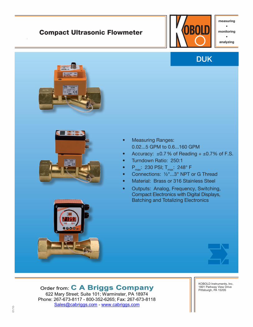
Compact Ultrasonic Flowmeter
• Measuring Ranges: 0.02...5 GPM to 0.6...160 GPM • Accuracy: ±0.7 % of Reading + ±0.7% of F.S. • Turndown Ratio: 250:1 • Pmax: 230 PSI; Tmax: 248° F • Connections: ½"...3" NPT or G Thread • Material: Brass or 316 Stainless Steel
• Outputs: Analog, Frequency, Switching, Compact Electronics with Digital Displays, Batching and Totalizing Electronics
OOrrddeerr ffrroomm:: CC AA BBrriiggggss CCoommppaannyy 622 Mary Street; Suite 101; Warminster, PA 18974
Phone: 267-673-8117 - 800-352-6265; Fax: 267-673-8118 [email protected] - www.cabriggs.com
2
Compact Ultrasonic Flowmeter Model DUK
No responsibility taken for errors; subject to change without prior notice.
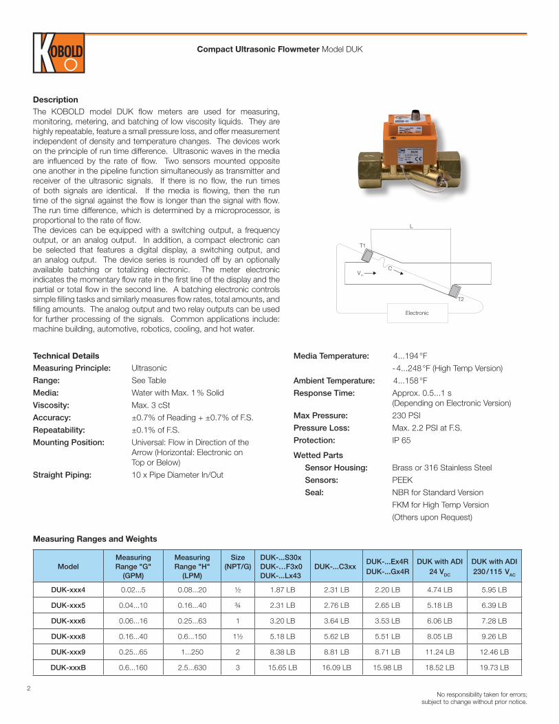
DescriptionThe KOBOLD model DUK flow meters are used for measuring, monitoring, metering, and batching of low viscosity liquids. They are highly repeatable, feature a small pressure loss, and offer measurement independent of density and temperature changes. The devices work on the principle of run time difference. Ultrasonic waves in the media are influenced by the rate of flow. Two sensors mounted opposite one another in the pipeline function simultaneously as transmitter and receiver of the ultrasonic signals. If there is no flow, the run times of both signals are identical. If the media is flowing, then the run time of the signal against the flow is longer than the signal with flow. The run time difference, which is determined by a microprocessor, is proportional to the rate of flow.The devices can be equipped with a switching output, a frequency output, or an analog output. In addition, a compact electronic can be selected that features a digital display, a switching output, and an analog output. The device series is rounded off by an optionally available batching or totalizing electronic. The meter electronic indicates the momentary flow rate in the first line of the display and the partial or total flow in the second line. A batching electronic controls simple filling tasks and similarly measures flow rates, total amounts, and filling amounts. The analog output and two relay outputs can be used for further processing of the signals. Common applications include: machine building, automotive, robotics, cooling, and hot water.
Electronic
L
T2
T1
Vm
C
Media Temperature: 4...194 °F
- 4...248 °F (High Temp Version)
Ambient Temperature: 4...158 °F
Response Time: Approx. 0.5...1 s (Depending on Electronic Version)
Max Pressure: 230 PSI
Pressure Loss: Max. 2.2 PSI at F.S.
Protection: IP 65
Wetted Parts
Sensor Housing: Brass or 316 Stainless Steel
Sensors: PEEK
Seal: NBR for Standard Version
FKM for High Temp Version
(Others upon Request)
Technical Details Measuring Principle: Ultrasonic
Range: See Table
Media: Water with Max. 1 % Solid
Viscosity: Max. 3 cSt
Accuracy: ±0.7% of Reading + ±0.7% of F.S.
Repeatability: ±0.1% of F.S.
Mounting Position: Universal: Flow in Direction of the Arrow (Horizontal: Electronic on Top or Below)
Straight Piping: 10 x Pipe Diameter In/Out
ModelMeasuring Range "G"
(GPM)
Measuring Range "H"
(LPM)
Size (NPT/G)
DUK-...S30x DUK-…F3x0 DUK-...Lx43
DUK-...C3xx DUK-...Ex4R DUK-...Gx4R
DUK with ADI24 VDC
DUK with ADI230 / 115 VAC
DUK-xxx4 0.02...5 0.08...20 ½ 1.87 LB 2.31 LB 2.20 LB 4.74 LB 5.95 LB
DUK-xxx5 0.04...10 0.16...40 ¾ 2.31 LB 2.76 LB 2.65 LB 5.18 LB 6.39 LB
DUK-xxx6 0.06...16 0.25...63 1 3.20 LB 3.64 LB 3.53 LB 6.06 LB 7.28 LB
DUK-xxx8 0.16...40 0.6...150 1½ 5.18 LB 5.62 LB 5.51 LB 8.05 LB 9.26 LB
DUK-xxx9 0.25...65 1...250 2 8.38 LB 8.81 LB 8.71 LB 11.24 LB 12.46 LB
DUK-xxxB 0.6...160 2.5...630 3 15.65 LB 16.09 LB 15.98 LB 18.52 LB 19.73 LB
Measuring Ranges and Weights

3
Compact Ultrasonic Flowmeter Model DUK
No responsibility taken for errors; subject to change without prior notice.
DUK-..S300, DUK-..S30D (Switching Output)
Display: Bi-color LED for Switch Status Switching Output (..S300): SPDT Relay, max. 1 A / 30 VDC
Switching Output (..S30D): Active 24 VDC, N/C and N/O Switch Point: 10...90 % of f.s. in 10 % Steps, Configurable by the Customer Using a Rotary Switch Power Supply: 24 VDC ± 20 % Power Consumption: 30 mA Electrical Connection: Plug M 12x1 Max Range Overflow: Flashing Bi-color LED from 105% of full scale
DUK-..F300, DUK-..F390 (Frequency Output) Pulse Output: PNP, Open Collector, max. 200 mA Frequency at F.S.: 500 Hz (..F300) 50 to 1000 Hz (..F390) User Specified Power Supply: 24 VDC ± 20 % Power Consumption: 25 mA Electrical Connection: Plug M 12x1 Max Range Overflow: Frequency output approx 2k from 105% of full scaleDUK-..L343 (Analog Output) Analog Output: 4-20 mA, 3-wire Load: Max. 500 Ω Power Supply: 24 VDC ± 20 % Power Consumption: Max. 45 mA Electrical Connection: Plug M 12x1
DUK-..L443 (Analog Output) Output: 4 - 20 mA, 3-wire Load: Max. 500 Ω Power Supply: 24 VDC ± 20 % Power Consumption: Max. 45 mA Electrical Connection: Plug DIN 43650
DUK-..C3xx (Compact Electronic) Display: 3-digit LED Analog Output: 4-20 mA Adjustable (only DUK-..C34x) Load: Max. 500 Ω Switching Output: 1(2x) Semiconductor PNP or NPN
Contact Function: N/C-N/O-Frequency Programmable (Approx. 1400 Hz at F.S., Uncalibrated) Settings: Via 2 Buttons Power Supply: 24 VDC ± 20 % Power Consumption: Approx. 100 mA Electrical Connection: Plug M 12x1
DUK-..Ex4R (Totalizing Electronic)
Display: LCD, 2 x 8 Digits, Illuminated Rate, Total and Grand Total, Units Selectable Analog Output: 4-20 mA Adjustable Load: Max. 500 Ω Switching Output: Relay (2x), Max. 30 V/2 A, 60 VA Settings: Via 4 Buttons Functions: Reset, MIN/MAX Memory, Flow Rate, Total and Grand Total, Language Power Supply: 24 VDC ± 20 %, 3-wire Power Consumption: Approx. 170 mA Electrical Connection: Cable Connection or M12x1 Plug
DUK-..Gx4R (Batching Electronic)
Display: LCD, 2 x 8 Digits, Illuminated Batching, Total and Grand Total, Units Selectable Analog Output: 4-20 mA, Adjustable Load: Max. 500 Ω Switching Output: Relay (2x), Max. 30 V / 2 A, 60 VA Settings: Via 4 Buttons Functions: Batching (Relay S2), Start, Stop, Reset, Fine Batching, Correction Amount, Flow Switch, Total Quantity, Language Power Supply: 24 VDC ± 20 %, 3-wire Power Consumption: Approx. 170 mA Electrical Connection: Cable Connection or M12 Plug
DUK-..Kxx2 (ADI-1 Electronic) Display: Bar Graph and 5-Digit Digital Combination Display; Batch System Analog Output: 4-20 mA, 0-10 V
Switching Output: 2 x Relays / SPDT Max. 250 VAC, 5A Resistive Load Max. 30 VDC / 5 A Settings: Via 4 Buttons Power Supply: 100-240 VAC, ±10% or 18-30 VAC /10-40 VDC
Electrical Connection: Terminal Block via Cable Gland
Electrical Specifications

4
Compact Ultrasonic Flowmeter Model DUK
No responsibility taken for errors; subject to change without prior notice.
Order Details (Example: DUK-11 N4 G S300 L) Note: Flow range determined by fitting size and can be referenced on the measuring range and weight table located on page 2
Model / Housing Material
Connection* Output / ElectronicFlow
Direction
DUK-11.. = Brass
DUK-12.. = SS
DUK-21.. = High Temp. Brass
DUK-22.. = High Temp. SS
..N4G.. = ½" NPT
..N5G.. = ¾" NPT
..N6G.. = 1" NPT
..N8G.. = 1½" NPT
..N9G.. = 2" NPT
..NBG.. = 3" NPT
..G4G.. = G ½
..G5G.. = G ¾
..G6G.. = G 1
..G8G.. = G 1½
..G9G.. = G 2
..GBG.. = G 3
Switching Output..S300.. = Relay, M12-Plug..S30D.. = Active 24 VDC, M12-Plug
Frequency Output..F300.. = M12-Plug, 500 Hz..F390.. = M12-Plug, 50 to 1000 Hz (User Specified)
Analog Output..L343.. = M12-Plug, 4-20 mA..L443.. = DIN-Plug, 4-20 mA
Compact Electronic..C30R.. = Open Collector, PNP (2x)..C30M.. = Open Collector, NPN (2x)..C34P.. = 20 mA, Open Collector, PNP..C34N.. = 4-20 mA, Open Collector, NPN
ADI Electronic
Display Power Supply Output Contacts
K = Bar Graph/ digital display
0 = 100-230 VAC/DC
3 = 18-30 VAC
0-40 VDC
0 = without
4 = 4-20 mA, 0-10 VDC
2 = (2x) Relay SPDT
Totalizing Electronic..E14R.. = LCD, 4-20 mA, Relay (2x), 1 m Cable..E34R.. = LCD, 4-20 mA, Relay (2x), M12-Plug (2x)
Batching Electronic..G14R.. = LCD, 4-20 mA, Relay (2x), 1 m Cable..G34R.. = LCD, 4-20 mA, Relay (2x), M12-Plug (2x)
..L = from Left to Right
..R = from Right to Left
..T = from Top to Bottom
..B = from Bottom to Top
Accessories: P/N 807.037 = 4-Pin Micro-DC Connector with 6-foot Cable for Output Types F300, F390, L 343, & S30D P/N 807.007 = 5-Pin Micro-DC Connector with 6-foot Cable for Output Types C3xx, S300, E34R, & G34R
P/N 807.087 = 8-Pin Micro-DC Connector with 6-foot Cable for Output Types E34R & G34R
*Standard display in G/min, optional display L/min (code H instead of G)
Model G/NPTSW
(inch)H
(inch)L
(inch)B
(inch)
DUK-xxx4 ½ 1.18 2.24 4.49 ca.2.83
DUK-xxx5 ¾ 1.42 2.32 4.98 ca. 2.99
DUK-xxx6 1 1.81 2.48 5.75 ca. 3.15
DUK-xxx8 1½ 2.36 2.72 7.48 ca. 3.54
DUK-xxx9 2 2.99 2.91 9.37 ca. 3.82
DUK-xxxB 3 4.13 3.31 12.05 ca. 4.80
Dimensions DUK-Sensor
5
Compact Ultrasonic Flowmeter Model DUK
No responsibility taken for errors; subject to change without prior notice.
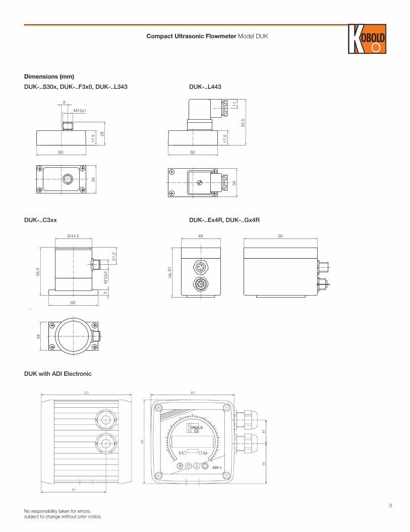
Dimensions (mm)
DUK-..S30x, DUK-..F3x0, DUK-..L343 DUK-..L443
DUK-..C3xx DUK-..Ex4R, DUK-..Gx4R
DUK with ADI Electronic
3417
.5
M12x1
828
60
34
55.5
11
60
17.5
58.5
21.2
M12
x1
34
Ø44.5
60
7
9048
ca. 6
1
S1 S2
START
STOP
PGM
ENTER
6
Compact Ultrasonic Flowmeter Model DUK
No responsibility taken for errors; subject to change without prior notice.
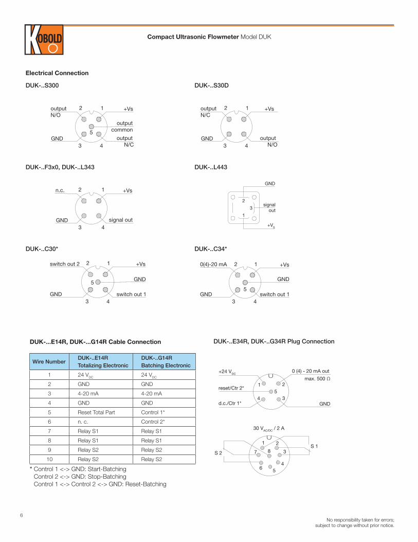
Electrical Connection
DUK-..S300 DUK-..S30D
DUK-..F3x0, DUK-..L343 DUK-..L443
DUK-..C30* DUK-..C34*
12
3 4
5
outputN/O
outputcommon
output N/C
+Vs
GND
12
3 4
outputN/C
output N/O
+Vs
GND
12
3 4
n.c.
signal out
+Vs
GND
12
3 4
n.c.
signal out
+Vs
GND
GND
signalout
+VS
1
2
3
12
3 4
5
+Vs
GND
GND
switch out 1
0(4)-20 mA12
3 4
5
switch out 2
switch out 1
+Vs
GND
GND
DUK-...E14R, DUK-...G14R Cable Connection
Wire NumberDUK-..E14R Totalizing Electronic
DUK-..G14R Batching Electronic
1 24 VDC 24 VDC
2 GND GND
3 4-20 mA 4-20 mA
4 GND GND
5 Reset Total Part Control 1*
6 n. c. Control 2*
7 Relay S1 Relay S1
8 Relay S1 Relay S1
9 Relay S2 Relay S2
10 Relay S2 Relay S2
* Control 1 <-> GND: Start-Batching Control 2 <-> GND: Stop-Batching Control 1 <-> Control 2 <-> GND: Reset-Batching
+24 VDC
reset/Ctr 2*
d.c./Ctr 1*
0 (4) - 20 mA out
GND
1 2
U
30 VAC/DC / 2 A
U
345
1 2
3
456
7S 1
S 2 8
max. 500 Ω
DUK-..E34R, DUK-..G34R Plug Connection