ductile iron pipes, fittings, accessories and their joints for water … · 2018-04-23 · en 805,...
TRANSCRIPT

BRITISH STANDARD BS EN 545:2006
Ductile iron pipes, fittings, accessories and their joints for water pipelines — Requirements and test methods
The European Standard EN 545:2006 has the status of a British Standard
ICS 23.040.10; 23.040.40
Lice
nsed
Cop
y: In
stitu
te O
f Tec
hnol
ogy
Tal
lagh
t, In
stitu
te o
f Tec
hnol
ogy,
Sat
Jun
09
05:0
8:15
GM
T+
00:0
0 20
07, U
ncon
trol
led
Cop
y, (
c) B
SI

BS EN 545:2006
This British Standard was published under the authority of the Standards Policy and Strategy Committee on 29 December 2006
© BSI 2006
ISBN 0 580 49821 2
National foreword
This British Standard was published by BSI. It is the UK implementation of EN 545:2006. It supersedes BS EN 545:2002 which is withdrawn. The UK participation in its preparation was entrusted to Technical Committee PSE/10, Iron pipes and fittings.A list of organizations represented on PSE/10 can be obtained on request to its secretary.This publication does not purport to include all the necessary provisions of a contract. Users are responsible for its correct application.Compliance with a British Standard cannot confer immunity from legal obligations.
Amendments issued since publication
Amd. No. Date Comments
Lice
nsed
Cop
y: In
stitu
te O
f Tec
hnol
ogy
Tal
lagh
t, In
stitu
te o
f Tec
hnol
ogy,
Sat
Jun
09
05:0
8:15
GM
T+
00:0
0 20
07, U
ncon
trol
led
Cop
y, (
c) B
SI
EUROPEAN STANDARD
NORME EUROPÉENNE
EUROPÄISCHE NORM
EN 545
November 2006
ICS 23.040.10; 23.040.40 Supersedes EN 545:2002
English Version
Ductile iron pipes, fittings, accessories and their joints for waterpipelines - Requirements and test methods
Tuyaux, raccords et accessoires en fonte ductile et leursassemblages pour canalisations d'eau - Prescriptions et
méthodes d'essai
Rohre, Formstücke, Zubehörteile aus duktilem Gusseisenund ihre Verbindungen für Wasserleitungen -
Anforderungen und Prüfverfahren
This European Standard was approved by CEN on 11 October 2006.
CEN members are bound to comply with the CEN/CENELEC Internal Regulations which stipulate the conditions for giving this EuropeanStandard the status of a national standard without any alteration. Up-to-date lists and bibliographical references concerning such nationalstandards may be obtained on application to the Central Secretariat or to any CEN member.
This European Standard exists in three official versions (English, French, German). A version in any other language made by translationunder the responsibility of a CEN member into its own language and notified to the Central Secretariat has the same status as the officialversions.
CEN members are the national standards bodies of Austria, Belgium, Cyprus, Czech Republic, Denmark, Estonia, Finland, France,Germany, Greece, Hungary, Iceland, Ireland, Italy, Latvia, Lithuania, Luxembourg, Malta, Netherlands, Norway, Poland, Portugal, Romania,Slovakia, Slovenia, Spain, Sweden, Switzerland and United Kingdom.
EUROPEAN COMMITTEE FOR STANDARDIZATIONC OM ITÉ EUR OP ÉEN DE NOR M ALIS AT IONEUROPÄISCHES KOMITEE FÜR NORMUNG
Management Centre: rue de Stassart, 36 B-1050 Brussels
© 2006 CEN All rights of exploitation in any form and by any means reservedworldwide for CEN national Members.
Ref. No. EN 545:2006: E
Lice
nsed
Cop
y: In
stitu
te O
f Tec
hnol
ogy
Tal
lagh
t, In
stitu
te o
f Tec
hnol
ogy,
Sat
Jun
09
05:0
8:15
GM
T+
00:0
0 20
07, U
ncon
trol
led
Cop
y, (
c) B
SI
EN 545:2006 (E)
2
Contents
Foreword......................................................................................................................................................................4 Introduction .................................................................................................................................................................5 1 Scope ..............................................................................................................................................................6 2 Normative references ....................................................................................................................................6 3 Terms and definitions ...................................................................................................................................7 4 Technical requirements ................................................................................................................................9 4.1 General............................................................................................................................................................9 4.2 Dimensional requirements..........................................................................................................................11 4.3 Material characteristics...............................................................................................................................15 4.4 Coatings and linings for pipes ...................................................................................................................16 4.5 Coatings for fittings and accessories........................................................................................................18 4.6 Marking of pipes and fittings......................................................................................................................19 4.7 Leak tightness..............................................................................................................................................20 5 Performance requirements for joints.........................................................................................................20 5.1 General..........................................................................................................................................................20 5.2 Flexible joints ...............................................................................................................................................20 5.3 Restrained flexible joints ............................................................................................................................22 5.4 Flanged joints...............................................................................................................................................22 5.5 Pipes with screwed or welded flanges ......................................................................................................23 6 Test methods................................................................................................................................................24 6.1 Pipe dimensions ..........................................................................................................................................24 6.2 Straightness of pipes ..................................................................................................................................25 6.3 Tensile testing..............................................................................................................................................25 6.4 Brinell hardness...........................................................................................................................................27 6.5 Works leak tightness test for pipes and fittings.......................................................................................27 6.6 Zinc mass .....................................................................................................................................................28 6.7 Thickness of paint coatings .......................................................................................................................29 6.8 Thickness of cement mortar lining ............................................................................................................29 7 Performance test methods .........................................................................................................................29 7.1 Compressive strength of the cement mortar lining .................................................................................29 7.2 Leak tightness of flexible joints to positive internal pressure................................................................30 7.3 Leak tightness of flexible joints to negative internal pressure...............................................................30 7.4 Leak tightness of flexible push-in joints to positive external pressure.................................................31 7.5 Leak tightness of flexible joints to dynamic internal pressure...............................................................31 7.6 Leak tightness and mechanical resistance of flanged joints..................................................................32 7.7 Leak tightness and mechanical resistance of screwed and welded flanges ........................................32 8 Tables of dimensions ..................................................................................................................................33 8.1 Socket and spigot pipes .............................................................................................................................33 8.2 Flanged pipes...............................................................................................................................................35 8.3 Fittings for socketed joints.........................................................................................................................35 8.4 Fittings for flanged joints............................................................................................................................51 Annex A (normative) Allowable pressures ...........................................................................................................72 A.1 General..........................................................................................................................................................72 A.2 Socket and spigot pipes (see 8.1) ..............................................................................................................72 A.3 Fittings for socketed joints (see 8.3) .........................................................................................................73 A.4 Flanged pipes (see 8.2) and fittings for flanged joints (see 8.4).............................................................73 Annex B (informative) Longitudinal bending resistance of pipes......................................................................75 Annex C (informative) Diametral stiffness of pipes .............................................................................................76 Annex D (informative) Alternative pipe coatings, field of use, characteristics of soils ...................................78 D.1 Alternative pipe coatings ............................................................................................................................78 Li
cens
ed C
opy:
Inst
itute
Of T
echn
olog
y T
alla
ght,
Inst
itute
of T
echn
olog
y, S
at J
un 0
9 05
:08:
15 G
MT
+00
:00
2007
, Unc
ontr
olle
d C
opy,
(c)
BS
I
EN 545:2006 (E)
3
D.2 Field of use, characteristics of soils..........................................................................................................79 Annex E (informative) Field of use, water characteristics ..................................................................................80 Annex F (informative) Quality assurance..............................................................................................................81 F.1 General..........................................................................................................................................................81 F.2 Performance tests .......................................................................................................................................81 F.3 Manufacturing process ...............................................................................................................................81 Annex G (informative) Calculation method of buried pipelines, heights of cover ...........................................83 G.1 Calculation method .....................................................................................................................................83 G.2 Heights of cover...........................................................................................................................................85 Bibliography..............................................................................................................................................................87
Lice
nsed
Cop
y: In
stitu
te O
f Tec
hnol
ogy
Tal
lagh
t, In
stitu
te o
f Tec
hnol
ogy,
Sat
Jun
09
05:0
8:15
GM
T+
00:0
0 20
07, U
ncon
trol
led
Cop
y, (
c) B
SI
EN 545:2006 (E)
4
Foreword
This document (EN 545:2006) has been prepared by Technical Committee CEN/TC 203 “Cast iron pipes, fittings and their joints”, the secretariat of which is held by AFNOR.
This European Standard shall be given the status of a national standard, either by publication of an identical text or by endorsement, at the latest by May 2007, and conflicting national standards shall be withdrawn at the latest by May 2007.
This document supersedes EN 545:2002.
According to the CEN/CENELEC Internal Regulations, the national standards organizations of the following countries are bound to implement this European Standard: Austria, Belgium, Cyprus, Czech Republic, Denmark, Estonia, Finland, France, Germany, Greece, Hungary, Iceland, Ireland, Italy, Latvia, Lithuania, Luxembourg, Malta, Netherlands, Norway, Poland, Portugal, Romania, Slovakia, Slovenia, Spain, Sweden, Switzerland and United Kingdom.
Lice
nsed
Cop
y: In
stitu
te O
f Tec
hnol
ogy
Tal
lagh
t, In
stitu
te o
f Tec
hnol
ogy,
Sat
Jun
09
05:0
8:15
GM
T+
00:0
0 20
07, U
ncon
trol
led
Cop
y, (
c) B
SI

EN 545:2006 (E)
5
Introduction
This standard is in conformity with the general requirements already established by CEN/TC 164 in the field of water supply.
In respect of potential adverse effects on the quality of water intended for human consumption, caused by the product covered by this standard:
this standard provides no information as to whether the product may be used without restriction in any of the member states of the EU or EFTA;
it should be noted that, while awaiting the adoption of verifiable European criteria, existing national regulations concerning the use and/or the characteristics of this product remain in force.
Lice
nsed
Cop
y: In
stitu
te O
f Tec
hnol
ogy
Tal
lagh
t, In
stitu
te o
f Tec
hnol
ogy,
Sat
Jun
09
05:0
8:15
GM
T+
00:0
0 20
07, U
ncon
trol
led
Cop
y, (
c) B
SI
EN 545:2006 (E)
6
1 Scope
This European Standard specifies the requirements and associated test methods applicable to ductile iron pipes, fittings, accessories and their joints for the construction of pipelines:
to convey water (e. g. potable water);
with or without pressure;
to be installed below or above ground.
This standard is applicable to pipes, fittings and accessories which are:
manufactured with socketed, flanged or spigot ends;
normally delivered externally and internally coated;
suitable for fluid temperatures between 0 °C and 50 °C, excluding frost.
This standard covers pipes, fittings and accessories cast by any type of foundry process or manufactured by fabrication of cast components, as well as corresponding joints, in a size range extending from DN 40 to DN 2 000, inclusive.
This standard specifies requirements for materials, dimensions and tolerances, mechanical properties and standard coatings of ductile iron pipes and fittings. It also gives performance requirements for all components including joints. Joint design and gasket shapes are outside the scope of this standard.
NOTE In this standard, all pressures are relative pressures, expressed in bars (100 kPa = 1 bar).
2 Normative references
The following referenced documents are indispensable for the application of this document. For dated references, only the edition cited applies. For undated references, the latest edition of the referenced document (including any amendments) applies.
EN 196-1, Methods of testing cement — Part 1: Determination of strength
EN 197-1, Cement — Part 1: Composition, specifications and conformity criteria for common cements
EN 681-1, Elastomeric seals — Materials requirements for pipe joint seals used in water and drainage applications — Part 1: Vulcanized rubber
EN 805, Water supply — Requirements for systems and components outside buildings
EN 1092-2, Flanges and their joints — Circular flanges for pipes, valves, fittings and accessories, PN designated — Part 2: Cast iron flanges
EN 10002-1, Metallic materials — Tensile testing — Part 1: Method of test at ambient temperature
EN ISO 4016, Hexagon head bolts — Product grade C (ISO 4016:1999)
EN ISO 4034, Hexagon nuts — Product grade C (ISO 4034:1999)
EN ISO 6506-1, Metallic materials — Brinell hardness test — Part 1: Test method (ISO 6506-1:2005)
EN ISO 7091, Plain washers — Normal series — Product grade C (ISO 7091:2000)
Lice
nsed
Cop
y: In
stitu
te O
f Tec
hnol
ogy
Tal
lagh
t, In
stitu
te o
f Tec
hnol
ogy,
Sat
Jun
09
05:0
8:15
GM
T+
00:0
0 20
07, U
ncon
trol
led
Cop
y, (
c) B
SI
EN 545:2006 (E)
7
3 Terms and definitions
For the purposes of this document, the following terms and definitions apply.
3.1 ductile iron cast iron used for pipes, fittings and accessories in which graphite is present substantially in spheroidal form
3.2 pipe casting of uniform bore, straight in axis, having socket, spigot or flanged ends, except for flanged-socket pieces, flanged-spigot pieces and collars which are classified as fittings
3.3 fitting casting other than a pipe which allows pipeline deviation, change of direction or bore
NOTE flanged-socket pieces, flanged spigot pieces and collars are also classified as fittings
3.4 accessory any casting other than a pipe or fitting which is used in a pipeline;
NOTE 1 for example:
glands and bolts for mechanical flexible joints (see 3.13);
glands, bolts and locking rings for restrained flexible joints (see 3.14);
pipe saddles for service cock connections;
adjustable flanges and flanges to be welded or screwed.
NOTE 2 Valves of all types are not covered by the term accessory.
3.5 flange flat circular end of a pipe or fitting extending perpendicular to its axis, with bolt holes equally spaced on a circle
NOTE A flange can be fixed (e.g. integrally cast or welded) or adjustable; an adjustable flange comprises a ring, in one or several parts assembled together, which bears on an end joint hub and can be freely rotated around the pipe axis before jointing.
3.6 spigot male end of a pipe or fitting
3.7 spigot end maximum insertion depth of the spigot plus 50 mm
3.8 socket female end of a pipe or fitting to make the connection with the spigot of the next component
3.9 gasket sealing component of a joint
3.10 joint connection between the ends of two pipes and/or fittings in which a gasket is used to effect a seal
Lice
nsed
Cop
y: In
stitu
te O
f Tec
hnol
ogy
Tal
lagh
t, In
stitu
te o
f Tec
hnol
ogy,
Sat
Jun
09
05:0
8:15
GM
T+
00:0
0 20
07, U
ncon
trol
led
Cop
y, (
c) B
SI
EN 545:2006 (E)
8
3.11 flexible joint joint which permits significant angular deflection both during and after installation and which can accept a slight offset of the centreline
3.12 push-in flexible joint flexible joint assembled by pushing the spigot through the gasket in the socket of the mating component
3.13 mechanical flexible joint flexible joint in which sealing is obtained by applying pressure to the gasket by mechanical means, e.g. a gland
3.14 restrained flexible joint flexible joint in which a means is provided to prevent separation of the assembled joint
3.15 flanged joint joint between two flanged ends
3.16 nominal size (DN) alphanumerical designation of size for components of a pipework system, which is used for reference purposes. It comprises the letters DN followed by a dimensionless whole number which is indirectly related to the physical size, in millimetres, of the bore or outside diameter of the end connections
[EN ISO 6708:1995]
3.17 nominal pressure (PN) alphanumerical designation used for reference purposes related to a combination of mechanical and dimensional characteristics of a component of a pipework system. It comprises the letters PN followed by a dimensionless number
[EN 1333:2006]
NOTE All equipment of the same nominal size DN designated by the same PN number have compatible mating dimensions.
3.18 leak tightness test pressure pressure applied to a component during manufacture in order to ensure its leak tightness
3.19 allowable operating pressure (PFA) maximum hydrostatic pressure that a component is capable of withstanding continuously in service
[EN 805:2000]
3.20 allowable maximum operating pressure (PMA) maximum pressure occurring from time to time, including surge, that a component is capable of withstanding in service
[EN 805:2000]
3.21 allowable test pressure (PEA) maximum hydrostatic pressure that a newly installed component is capable of withstanding for a relatively short duration, in order to insure the integrity and tightness of the pipeline Li
cens
ed C
opy:
Inst
itute
Of T
echn
olog
y T
alla
ght,
Inst
itute
of T
echn
olog
y, S
at J
un 0
9 05
:08:
15 G
MT
+00
:00
2007
, Unc
ontr
olle
d C
opy,
(c)
BS
I
EN 545:2006 (E)
9
[EN 805:2000]
NOTE This test pressure is different from the system test pressure (STP), which is related to the design pressure of the pipeline and is intended to ensure its integrity and leak tightness ; see also A.1.
3.22 diametral stiffness of a pipe characteristic of a pipe which allows it to resist ovalization under loading when installed
3.23 performance test proof of design test which is done once and is repeated only after change of design
3.24 length effective length of a pipe or fitting, as shown on Figure 4 for pipes and on Figures 5 to 21 for fittings
NOTE For flanged pipes and fittings, the effective length L (l for branches) is equal to the overall length. For socketed pipes and fittings, the effective length LU (lu, for branches), is equal to the overall length minus the maximum spigot insertion depth as given in the manufacturer’s catalogues.
3.25 deviation design Iength allowance with respect to the standardized length of a pipe or a fitting
3.26 ovality out of roundness of a pipe section;
NOTE it is equal to:
+−
21
21100AAAA
(1)
where:
A1 is the maximum axis, in millimetres;
A2 is the minimum axis, in millimetres.
4 Technical requirements
4.1 General
4.1.1 Ductile iron pipes and fittings
Nominal sizes, thickness classes, lengths and coatings are specified in 4.1.1, 4.2.1, 4.2.3, 4.4 and 4.5 respectively. When, by agreement between manufacturer and purchaser, pipes and fittings with different wall thickness classes, lengths and/or coatings and other types of fittings than those given in 8.3 and 8.4, are supplied with reference to this standard, they shall comply with all the other requirements of this standard.
NOTE 1 Other types of fittings include angle branches, tees and tapers with other combinations DN x dn, draining tees, …
The standardized nominal sizes DN of pipes and fittings are as follows: (see EN 805) 40, 50, 60, 65, 80, 100, 125, 150, 200, 250, 300, 350, 400, 450, 500, 600, 700, 800, 900, 1 000, 1 100, 1 200, 1 400, 1 500, 1 600, 1 800, 2 000.
The allowable pressures of ductile iron pipes and fittings shall be as given in Annex A.
Lice
nsed
Cop
y: In
stitu
te O
f Tec
hnol
ogy
Tal
lagh
t, In
stitu
te o
f Tec
hnol
ogy,
Sat
Jun
09
05:0
8:15
GM
T+
00:0
0 20
07, U
ncon
trol
led
Cop
y, (
c) B
SI
EN 545:2006 (E)
10
NOTE 2 Annexes B and C give respectively the longitudinal bending resistance and the diametral stiffness of ductile iron pipes.
NOTE 3 When installed and operated under the conditions for which they are designed (see Annexes D, E and G), ductile iron pipes, fittings, accessories and their joints maintain all their functional characteristics over their operating life, due to the constant material properties, to the stability of their cross section and to their design with high safety factors.
4.1.2 Surface condition and repair
Pipes, fittings and accessories shall be free from defects and surface imperfections which can lead to non-compliance with Clause 4 and Clause 5.
When necessary, pipes and fittings may be repaired, for example by welding, in order to remove surface imperfections and localized defects which do not extend through the entire wall thickness, provided that :
the repairs are carried out according to the manufacturer’s written procedure;
the repaired pipes and fittings comply with all the requirements of Clause 4 and Clause 5.
4.1.3 Types of joints and interconnection
4.1.3.1 General
Rubber gasket materials shall comply with the requirements of EN 681-1, type WA. When materials other than rubber are necessary (e.g. for flanged joints), they shall comply with the appropriate European Standard or, where no European Standard exists, the appropriate International Standard.
4.1.3.2 Flanged joints
Flanges shall be constructed in such a way that they can be attached to flanges whose dimensions and tolerances comply with EN 1092-2. This ensures interconnection between all flanged components (pipes, fittings, valves,....) of the same PN and DN and adequate joint performance.
Bolts and nuts shall comply as a minimum with the requirements of EN ISO 4016 and EN ISO 4034, grade 4.6. When applicable, washers shall comply with EN ISO 7091.
Although it does not affect interconnection, the manufacturer shall state in his catalogues whether his products are normally delivered with fixed flanges or adjustable flanges.
NOTE Flange gaskets can be one of those given in EN 1514.
4.1.3.3 Flexible joints
Pipes and fittings with flexible joints shall comply with 4.2.2.1 for their spigot external diameter DE and their tolerances. This offers the possibility of interconnection between components equipped with different types of flexible joints. In addition, each type of flexible joint shall be designed to fulfil the performance requirements of Clause 5.
NOTE 1 For interconnection with certain types of joints operating within a different tolerance range on DE, the manufacturer’s guidance should be followed as to the means of ensuring adequate joint performance at high pressures (e.g. measurement and selection of external diameter).
NOTE 2 For interconnection with existing pipelines which can have external diameters not in compliance with 4.2.2.1, the manufacturer’s guidance should be followed as to the appropriate means of interconnection (e.g. adaptors).
4.1.4 Materials in contact with water intended for human consumption
Ductile iron pipes, fittings and their joints include several materials given in this standard. When used under the conditions for which they are designed, in permanent or in temporary contact with water intended for human consumption, ductile iron pipes, fittings and their joints shall not change the quality of that water to such an extent that it fails to comply with the requirements of national regulations.
Lice
nsed
Cop
y: In
stitu
te O
f Tec
hnol
ogy
Tal
lagh
t, In
stitu
te o
f Tec
hnol
ogy,
Sat
Jun
09
05:0
8:15
GM
T+
00:0
0 20
07, U
ncon
trol
led
Cop
y, (
c) B
SI
EN 545:2006 (E)
11
For this purpose, reference shall be made to the relevant national regulations and standards, transposing EN standards when available, dealing with the influence of materials on water quality and to the requirements for external systems and components as given in EN 805.
NOTE A European Acceptance Scheme (EAS) is in course of development in relation to the Construction Products Directive and to the Drinking Water Directive ; its requirements will be introduced in this standard when completed.
4.2 Dimensional requirements
4.2.1 Wall thickness
4.2.1.1 General
The thickness shall be calculated either by the K class formula for pipes and fittings (see 4.2.1.2) or defined according to 4.2.1.3 for Class 40 pipes of DN 40 to DN 400.
For pipes, the standardized thickness classes are given in 8.1. Other thicknesses are possible for pipes by agreement between manufacturer and purchaser.
For fittings, the thickness e given in tables and on figures of 8.3 and 8.4 is the nominal thickness corresponding to the main part of the body. The actual thickness at any particular point may be increased to meet localized high stresses depending on the shape of the casting (e.g. at internal radius of bends, at the branch-body junction of tees,...).
Annex A gives the maximum values of PFA, PMA and PEA.
4.2.1.2 K classes for pipes and fittings
The nominal iron wall thickness of pipes and fittings is given as a function of the nominal size, DN, by the following formula, with a minimum of 6 mm for pipes and 7 mm for fittings:
e = K(0,5 + 0,001 DN) (2)
where:
e is the nominal wall thickness, in millimetres;
DN is the nominal size;
K is a coefficient used for the determination of the thickness. It is selected from a series of whole numbers :.... 8, 9, 10, 11, 12.....
4.2.1.3 Class 40 for pipes
The nominal iron wall thickness of pipes DN 40 to DN 400 is given as a function of the nominal size, DN, in Table 15.
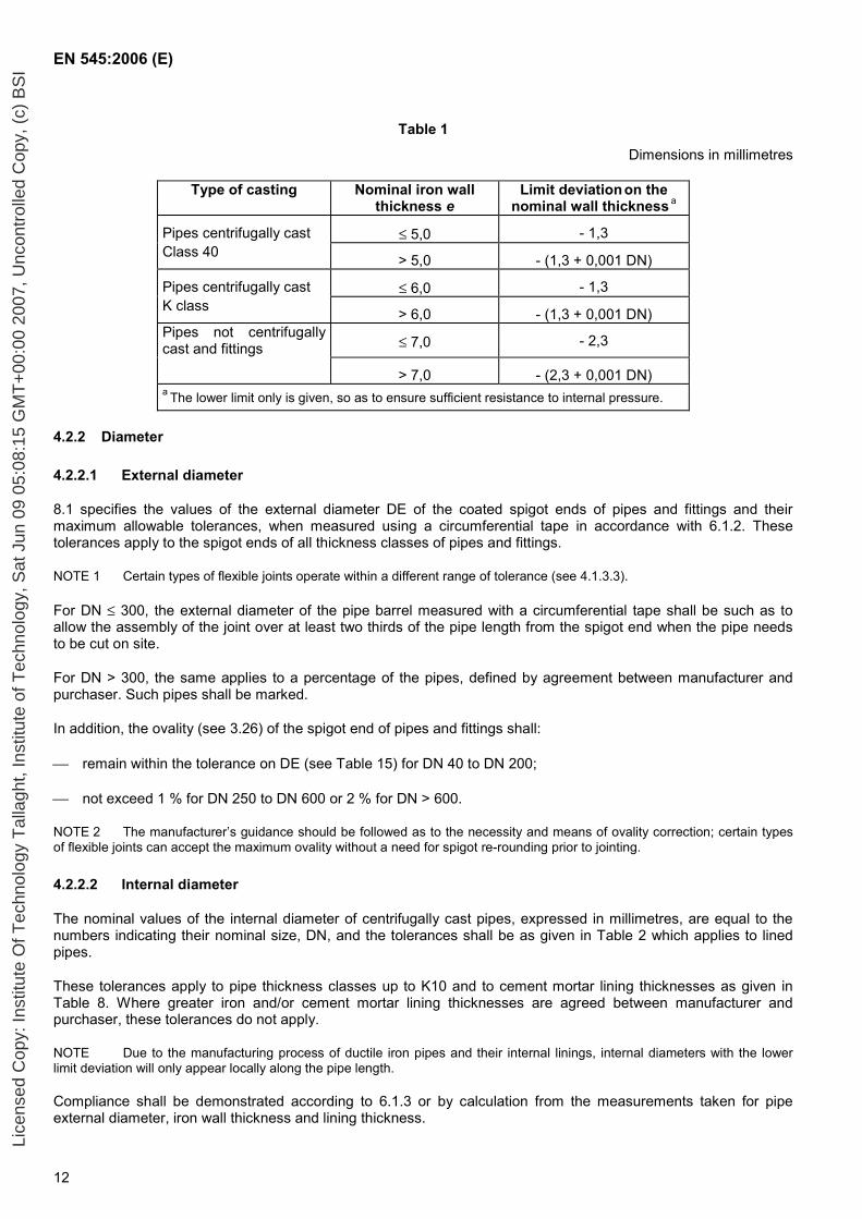
4.2.1.4 Tolerance
The tolerance on the nominal wall thickness of pipes and fittings shall be as given in Table 1. The measurement of the wall thickness shall be in accordance with 6.1.1.
Lice
nsed
Cop
y: In
stitu
te O
f Tec
hnol
ogy
Tal
lagh
t, In
stitu
te o
f Tec
hnol
ogy,
Sat
Jun
09
05:0
8:15
GM
T+
00:0
0 20
07, U
ncon
trol
led
Cop
y, (
c) B
SI
EN 545:2006 (E)
12
Table 1
Dimensions in millimetres
Type of casting Nominal iron wall thickness e
Limit deviation on the nominal wall thickness a
Pipes centrifugally cast ≤ 5,0 - 1,3 Class 40 > 5,0 - (1,3 + 0,001 DN)
Pipes centrifugally cast ≤ 6,0 - 1,3 K class > 6,0 - (1,3 + 0,001 DN) Pipes not centrifugally cast and fittings ≤ 7,0 - 2,3
> 7,0 - (2,3 + 0,001 DN) a The lower limit only is given, so as to ensure sufficient resistance to internal pressure.
4.2.2 Diameter
4.2.2.1 External diameter
8.1 specifies the values of the external diameter DE of the coated spigot ends of pipes and fittings and their maximum allowable tolerances, when measured using a circumferential tape in accordance with 6.1.2. These tolerances apply to the spigot ends of all thickness classes of pipes and fittings.
NOTE 1 Certain types of flexible joints operate within a different range of tolerance (see 4.1.3.3).
For DN ≤ 300, the external diameter of the pipe barrel measured with a circumferential tape shall be such as to allow the assembly of the joint over at least two thirds of the pipe length from the spigot end when the pipe needs to be cut on site.
For DN > 300, the same applies to a percentage of the pipes, defined by agreement between manufacturer and purchaser. Such pipes shall be marked.
In addition, the ovality (see 3.26) of the spigot end of pipes and fittings shall:
remain within the tolerance on DE (see Table 15) for DN 40 to DN 200;
not exceed 1 % for DN 250 to DN 600 or 2 % for DN > 600.
NOTE 2 The manufacturer’s guidance should be followed as to the necessity and means of ovality correction; certain types of flexible joints can accept the maximum ovality without a need for spigot re-rounding prior to jointing.
4.2.2.2 Internal diameter
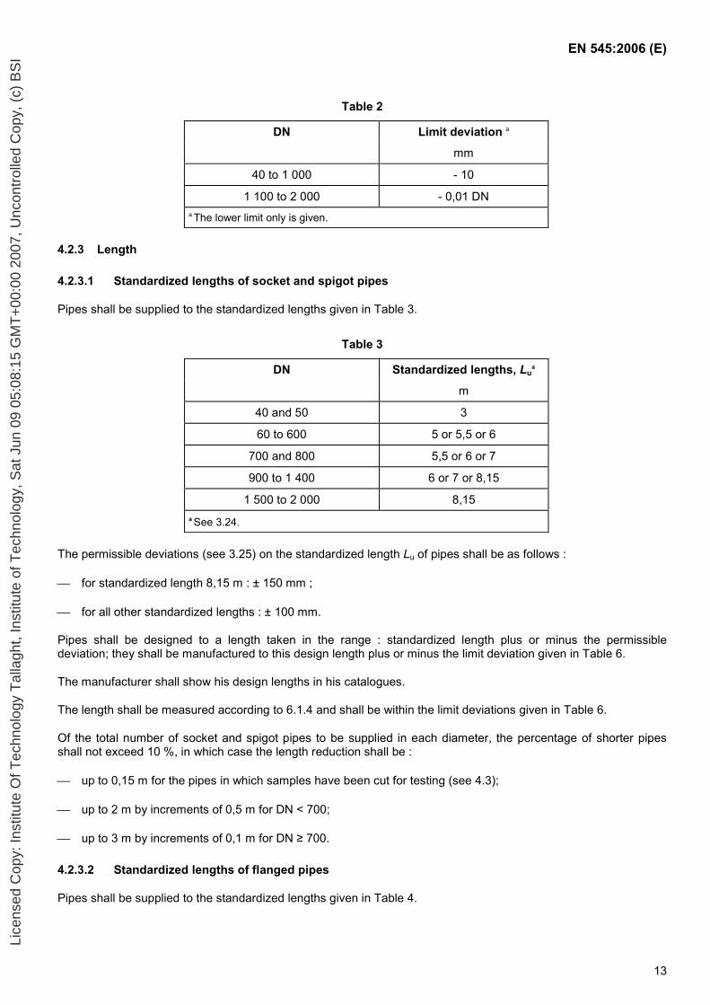
The nominal values of the internal diameter of centrifugally cast pipes, expressed in millimetres, are equal to the numbers indicating their nominal size, DN, and the tolerances shall be as given in Table 2 which applies to lined pipes.
These tolerances apply to pipe thickness classes up to K10 and to cement mortar lining thicknesses as given in Table 8. Where greater iron and/or cement mortar lining thicknesses are agreed between manufacturer and purchaser, these tolerances do not apply.
NOTE Due to the manufacturing process of ductile iron pipes and their internal linings, internal diameters with the lower limit deviation will only appear locally along the pipe length.
Compliance shall be demonstrated according to 6.1.3 or by calculation from the measurements taken for pipe external diameter, iron wall thickness and lining thickness.
Lice
nsed
Cop
y: In
stitu
te O
f Tec
hnol
ogy
Tal
lagh
t, In
stitu
te o
f Tec
hnol
ogy,
Sat
Jun
09
05:0
8:15
GM
T+
00:0
0 20
07, U
ncon
trol
led
Cop
y, (
c) B
SI
EN 545:2006 (E)
13
Table 2
DN Limit deviation a
mm
40 to 1 000 - 10
1 100 to 2 000 - 0,01 DN a The lower limit only is given.
4.2.3 Length
4.2.3.1 Standardized lengths of socket and spigot pipes
Pipes shall be supplied to the standardized lengths given in Table 3.
Table 3
DN Standardized lengths, Lua
m
40 and 50 3
60 to 600 5 or 5,5 or 6
700 and 800 5,5 or 6 or 7
900 to 1 400 6 or 7 or 8,15
1 500 to 2 000 8,15 a See 3.24.
The permissible deviations (see 3.25) on the standardized length Lu of pipes shall be as follows :
for standardized length 8,15 m : ± 150 mm ;
for all other standardized lengths : ± 100 mm.
Pipes shall be designed to a length taken in the range : standardized length plus or minus the permissible deviation; they shall be manufactured to this design length plus or minus the limit deviation given in Table 6.
The manufacturer shall show his design lengths in his catalogues.
The length shall be measured according to 6.1.4 and shall be within the limit deviations given in Table 6.
Of the total number of socket and spigot pipes to be supplied in each diameter, the percentage of shorter pipes shall not exceed 10 %, in which case the length reduction shall be :
up to 0,15 m for the pipes in which samples have been cut for testing (see 4.3);
up to 2 m by increments of 0,5 m for DN < 700;
up to 3 m by increments of 0,1 m for DN ≥ 700.
4.2.3.2 Standardized lengths of flanged pipes
Pipes shall be supplied to the standardized lengths given in Table 4.
Lice
nsed
Cop
y: In
stitu
te O
f Tec
hnol
ogy
Tal
lagh
t, In
stitu
te o
f Tec
hnol
ogy,
Sat
Jun
09
05:0
8:15
GM
T+
00:0
0 20
07, U
ncon
trol
led
Cop
y, (
c) B
SI
EN 545:2006 (E)
14
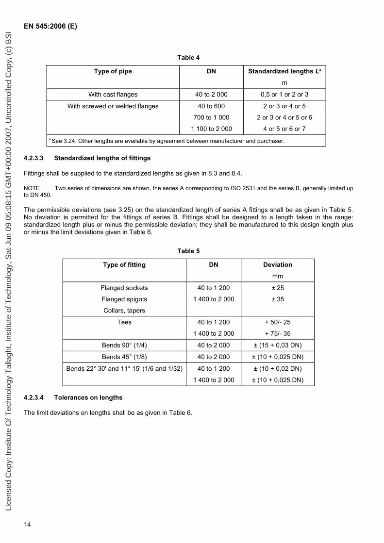
Table 4
Type of pipe DN Standardized lengths La
m
With cast flanges 40 to 2 000 0,5 or 1 or 2 or 3
With screwed or welded flanges 40 to 600 2 or 3 or 4 or 5
700 to 1 000 2 or 3 or 4 or 5 or 6
1 100 to 2 000 4 or 5 or 6 or 7 a See 3.24. Other lengths are available by agreement between manufacturer and purchaser.
4.2.3.3 Standardized lengths of fittings
Fittings shall be supplied to the standardized lengths as given in 8.3 and 8.4.
NOTE Two series of dimensions are shown, the series A corresponding to ISO 2531 and the series B, generally limited up to DN 450.
The permissible deviations (see 3.25) on the standardized length of series A fittings shall be as given in Table 5. No deviation is permitted for the fittings of series B. Fittings shall be designed to a length taken in the range: standardized length plus or minus the permissible deviation; they shall be manufactured to this design length plus or minus the limit deviations given in Table 6.
Table 5
Type of fitting DN Deviation
mm
Flanged sockets 40 to 1 200 ± 25
Flanged spigots 1 400 to 2 000 ± 35
Collars, tapers
Tees 40 to 1 200 + 50/- 25
1 400 to 2 000 + 75/- 35
Bends 90° (1/4) 40 to 2 000 ± (15 + 0,03 DN)
Bends 45° (1/8) 40 to 2 000 ± (10 + 0,025 DN)
Bends 22° 30' and 11° 15' (1/6 and 1/32) 40 to 1 200 ± (10 + 0,02 DN)
1 400 to 2 000 ± (10 + 0,025 DN)
4.2.3.4 Tolerances on lengths
The limit deviations on lengths shall be as given in Table 6.
Lice
nsed
Cop
y: In
stitu
te O
f Tec
hnol
ogy
Tal
lagh
t, In
stitu
te o
f Tec
hnol
ogy,
Sat
Jun
09
05:0
8:15
GM
T+
00:0
0 20
07, U
ncon
trol
led
Cop
y, (
c) B
SI
EN 545:2006 (E)
15
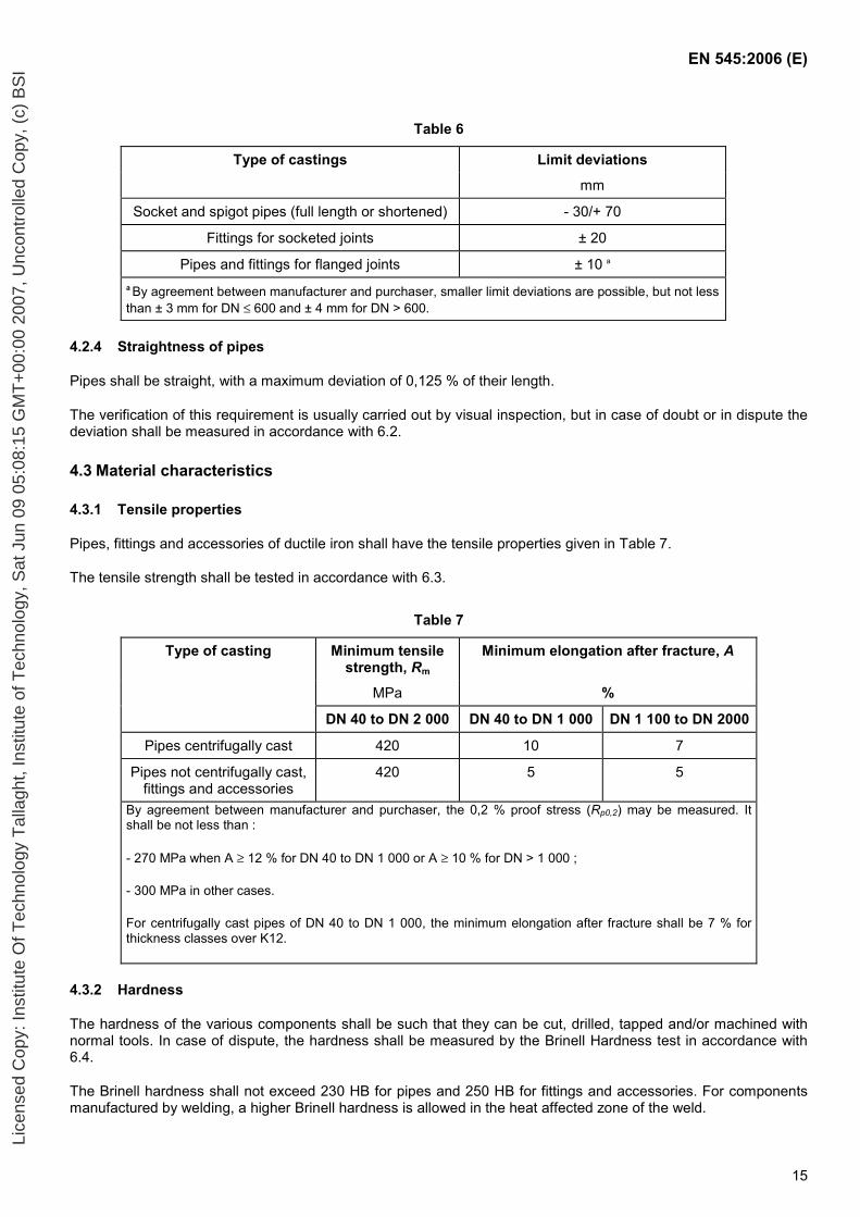
Table 6
Type of castings Limit deviations
mm
Socket and spigot pipes (full length or shortened) - 30/+ 70
Fittings for socketed joints ± 20
Pipes and fittings for flanged joints ± 10 a a By agreement between manufacturer and purchaser, smaller limit deviations are possible, but not less than ± 3 mm for DN ≤ 600 and ± 4 mm for DN > 600.
4.2.4 Straightness of pipes
Pipes shall be straight, with a maximum deviation of 0,125 % of their length.
The verification of this requirement is usually carried out by visual inspection, but in case of doubt or in dispute the deviation shall be measured in accordance with 6.2.
4.3 Material characteristics
4.3.1 Tensile properties
Pipes, fittings and accessories of ductile iron shall have the tensile properties given in Table 7.
The tensile strength shall be tested in accordance with 6.3.
Table 7
Type of casting Minimum tensile strength, Rm
Minimum elongation after fracture, A
MPa %
DN 40 to DN 2 000 DN 40 to DN 1 000 DN 1 100 to DN 2000
Pipes centrifugally cast 420 10 7
Pipes not centrifugally cast, fittings and accessories
420 5 5
By agreement between manufacturer and purchaser, the 0,2 % proof stress (Rp0,2) may be measured. It shall be not less than :
- 270 MPa when A ≥ 12 % for DN 40 to DN 1 000 or A ≥ 10 % for DN > 1 000 ;
- 300 MPa in other cases.
For centrifugally cast pipes of DN 40 to DN 1 000, the minimum elongation after fracture shall be 7 % for thickness classes over K12.
4.3.2 Hardness
The hardness of the various components shall be such that they can be cut, drilled, tapped and/or machined with normal tools. In case of dispute, the hardness shall be measured by the Brinell Hardness test in accordance with 6.4.
The Brinell hardness shall not exceed 230 HB for pipes and 250 HB for fittings and accessories. For components manufactured by welding, a higher Brinell hardness is allowed in the heat affected zone of the weld.
Lice
nsed
Cop
y: In
stitu
te O
f Tec
hnol
ogy
Tal
lagh
t, In
stitu
te o
f Tec
hnol
ogy,
Sat
Jun
09
05:0
8:15
GM
T+
00:0
0 20
07, U
ncon
trol
led
Cop
y, (
c) B
SI
EN 545:2006 (E)
16
4.4 Coatings and linings for pipes
4.4.1 General
Unless otherwise agreed between manufacturer and purchaser, all pipes shall be delivered with an external metallic zinc coating with finishing layer in accordance with 4.4.2, and an internal lining of cement mortar in accordance with 4.4.3.
The joint areas are generally coated as follows:
external surface of spigot ends : same as external pipe coating;
flanges and sockets (face and internal surface): bituminous paint or synthetic resin paint, alone or as a supplement to a primer or zinc coating.
Other coatings may also be supplied, depending on the external and internal conditions of use (see Annex D).
These external and internal coatings shall comply with the corresponding European Standards or, where no European Standards exists, they shall comply with International Standards or with National Standards, or with an agreed technical specification.
All finished internal coatings (linings) shall comply with 4.1.4.
NOTE 1 The field of use of these coatings and linings is given in Annexes D and E.
NOTE 2 Pipes with cast flanges can be coated as fittings (see 4.5).
NOTE 3 The maximum fluid temperature is limited to 35°C for some polymeric coatings. If such coatings are to be used at higher temperatures, additional performance testing should be carried out.
4.4.2 External coating of zinc with finishing layer
4.4.2.1 General
The external coating of centrifugally cast ductile iron pipes shall comprise a layer of metallic zinc, covered by a finishing layer of a bituminous product or synthetic resin compatible with zinc. Both layers shall be works applied.
The zinc is normally applied on oxide-surfaced pipes after heat treatment; at the manufacturer’s option, it may also be applied on blast-cleaned pipes. Prior to application of zinc, the pipe surface shall be dry and free from rust or non-adhering particles or foreign matter such as oil or grease.
4.4.2.2 Coatings characteristics
The metallic zinc coating shall cover the external surface of the pipe and provide a dense, continuous, uniform layer. It shall be free from such defects as bare patches or lack of adhesion. The uniformity of the coating shall be checked by visual inspection. When measured in accordance with 6.6, the mean mass of zinc per unit area shall be not less than 130 g/m². The purity of the zinc used shall be at least 99,99%.
The finishing layer shall uniformly cover the whole surface of the metallic zinc layer and be free from such defects as bare patches or lack of adhesion. The uniformity of the finishing layer shall be checked by visual inspection. When measured in accordance with 6.7, the mean thickness of the finishing layer shall be not less than 70 µm and the local minimum thickness not less than 50 µm.
4.4.2.3 Repairs
Damage to coatings where the area of total removal of zinc and finishing layer has a width exceeding 5 mm and areas left uncoated (e.g. under test token, see 6.6) shall be repaired.
Repairs shall be carried out by :
Lice
nsed
Cop
y: In
stitu
te O
f Tec
hnol
ogy
Tal
lagh
t, In
stitu
te o
f Tec
hnol
ogy,
Sat
Jun
09
05:0
8:15
GM
T+
00:0
0 20
07, U
ncon
trol
led
Cop
y, (
c) B
SI
EN 545:2006 (E)
17
metallic zinc spray complying with 4.4.2.2, or application of zinc-rich paint containing at least 90 % zinc by mass of dry film and with a mean mass of applied paint not less than 150 g/m²; and
application of a finishing layer complying with 4.4.2.2.
4.4.3 Internal lining of cement mortar
4.4.3.1 General
Unless specified in the corresponding European Standard, the internal cement mortar lining of ductile iron pipes shall comply with the following requirements.
The cement mortar lining of ductile iron pipes shall constitute a dense, homogeneous layer covering the total internal surface of the pipe barrel.
It shall be works-applied by a centrifugal spinning process or a centrifugal spray head or a combination of these methods. Smoothing with a trowel is permitted.
Prior to application of the lining, the metal surface shall be free from loose material and oil or grease.
The cement mortar mix shall comprise cement, sand and water. If admixtures are used, they shall comply with 4.1.4, and they shall be declared. The ratio by mass of sand to cement shall not exceed 3,5. At the mixing stage, the ratio by mass of total water to cement depends on the manufacturing process and shall be determined such that the lining is in accordance with 4.4.3.2 and 4.4.3.3.
The cement shall be one of those listed in EN 197-1 or sulphate resisting cement. High alumina cement may be used for raw water or for specific applications as agreed between manufacturer and purchaser. The cured lining shall comply with 4.1.4. The sand shall have an appropriate grading and shall not contain organic impurities or fine clay particles which may affect the lining quality. The water used in the mortar mix shall be drinking water or water of comparable quality.
After application of the fresh lining, controlled curing shall be carried out so as to provide sufficient hydration to the cement.
The cured lining shall comply with 4.1.4, 4.4.3.2 and 4.4.3.3.
4.4.3.2 Strength of the lining
When measured in accordance with 7.1, the compressive strength of the cement mortar after 28 days of curing shall be not less than 50 MPa.
NOTE The compressive strength of the lining is directly related to other functional properties such as high density, good bond and low porosity.
4.4.3.3 Thickness and surface condition
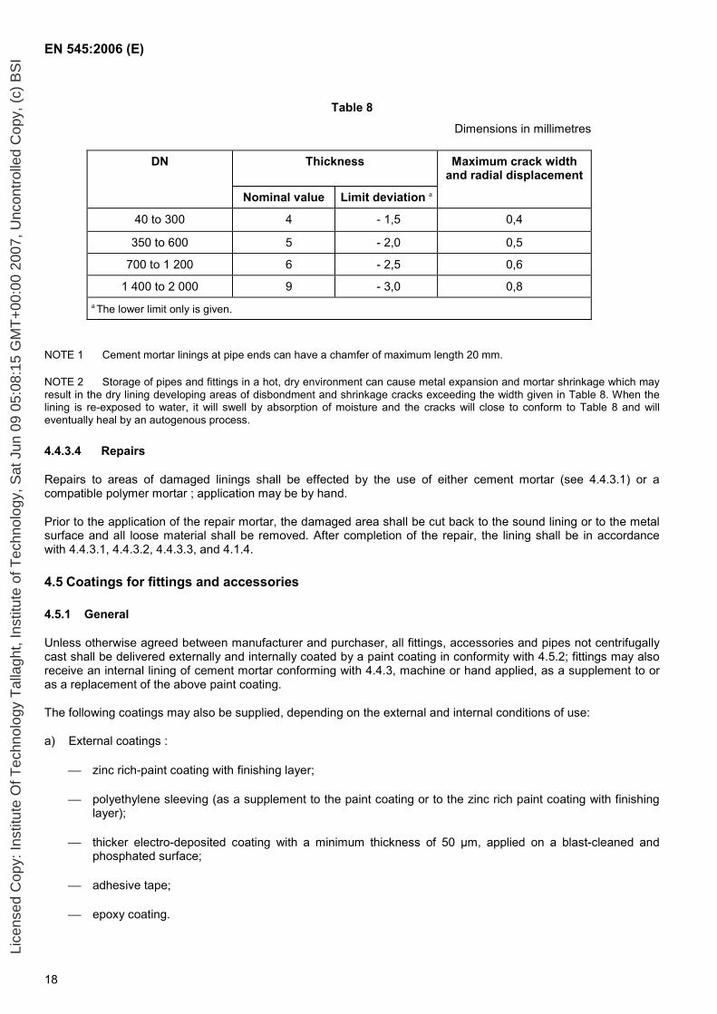
The nominal thickness of the cement mortar lining and its tolerance shall be as given in Table 8. When measured in accordance with 6.8, the lining thickness shall be within the specified tolerance.
The surface of the cement mortar lining shall be uniform and smooth. Trowel marks, protrusion of sand grains and surface texture inherent to the method of manufacture are acceptable. But there shall be no recesses or local defects which reduce the thickness to below the minimum value given in Table 8.
Fine crazing and hairline cracks associated with cement rich surface may appear in dry linings. When shrinkage cracks inherent to cement-bound materials have developed in the dry linings, the crack width and the corresponding radial displacement shall not exceed the values given in Table 8.
Lice
nsed
Cop
y: In
stitu
te O
f Tec
hnol
ogy
Tal
lagh
t, In
stitu
te o
f Tec
hnol
ogy,
Sat
Jun
09
05:0
8:15
GM
T+
00:0
0 20
07, U
ncon
trol
led
Cop
y, (
c) B
SI
EN 545:2006 (E)
18
Table 8
Dimensions in millimetres
DN Thickness Maximum crack width and radial displacement
Nominal value Limit deviation a
40 to 300 4 - 1,5 0,4
350 to 600 5 - 2,0 0,5
700 to 1 200 6 - 2,5 0,6
1 400 to 2 000 9 - 3,0 0,8 a The lower limit only is given.
NOTE 1 Cement mortar linings at pipe ends can have a chamfer of maximum length 20 mm.
NOTE 2 Storage of pipes and fittings in a hot, dry environment can cause metal expansion and mortar shrinkage which may result in the dry lining developing areas of disbondment and shrinkage cracks exceeding the width given in Table 8. When the lining is re-exposed to water, it will swell by absorption of moisture and the cracks will close to conform to Table 8 and will eventually heal by an autogenous process.
4.4.3.4 Repairs
Repairs to areas of damaged linings shall be effected by the use of either cement mortar (see 4.4.3.1) or a compatible polymer mortar ; application may be by hand.
Prior to the application of the repair mortar, the damaged area shall be cut back to the sound lining or to the metal surface and all loose material shall be removed. After completion of the repair, the lining shall be in accordance with 4.4.3.1, 4.4.3.2, 4.4.3.3, and 4.1.4.
4.5 Coatings for fittings and accessories
4.5.1 General
Unless otherwise agreed between manufacturer and purchaser, all fittings, accessories and pipes not centrifugally cast shall be delivered externally and internally coated by a paint coating in conformity with 4.5.2; fittings may also receive an internal lining of cement mortar conforming with 4.4.3, machine or hand applied, as a supplement to or as a replacement of the above paint coating.
The following coatings may also be supplied, depending on the external and internal conditions of use:
a) External coatings :
zinc rich-paint coating with finishing layer;
polyethylene sleeving (as a supplement to the paint coating or to the zinc rich paint coating with finishing layer);
thicker electro-deposited coating with a minimum thickness of 50 µm, applied on a blast-cleaned and phosphated surface;
adhesive tape;
epoxy coating.
Lice
nsed
Cop
y: In
stitu
te O
f Tec
hnol
ogy
Tal
lagh
t, In
stitu
te o
f Tec
hnol
ogy,
Sat
Jun
09
05:0
8:15
GM
T+
00:0
0 20
07, U
ncon
trol
led
Cop
y, (
c) B
SI
EN 545:2006 (E)
19
b) Internal coatings (linings):
thicker cement mortar lining;
cement mortar lining with seal coat;
thicker electro-deposited coating with a minimum thickness of 50 µm, applied on a blast-cleaned and phosphated surface;
polyurethane coating;
enamel coating;
epoxy coating.
These external and internal coatings shall comply with the corresponding European Standards or, where no European Standard exists, they shall comply with International Standards or with National Standards, or with an agreed technical specification.
All finished internal coatings (linings) shall comply with 4.1.4.
NOTE The field of use of these coatings and linings is given in Annexes D and E.
4.5.2 Paint coating
4.5.2.1 General
The coating material shall be of a bitumen or synthetic resin base. Appropriate additives (such as solvents, inorganic fillers, …) to allow easy application and drying are permitted. Prior to application of the coating, the casting surface shall be dry, free from rust or non adhering particles or foreign matter such as oil or grease. The coating shall be works-applied.
4.5.2.2 Coating characteristics
The coating shall uniformly cover the whole surface of the casting and have a smooth regular appearance. Drying shall be sufficient to ensure that it will not stick to adjacent coated pieces.
When measured in accordance with 6.7, the mean thickness of the coating shall be not less than 70 µm and the local minimum thickness shall be not less than 50 µm. For electro-deposited synthetic resin based coatings, the coating thickness shall be not less than 35 µm.
4.6 Marking of pipes and fittings
All pipes and fittings shall be legibly and durably marked and shall bear at least the following information:
the manufacturer’s name or mark;
the identification of the year of manufacture;
the identification as ductile iron;
the DN;
the PN rating of flanges when applicable;
the reference to this standard;
the class designation of centrifugally cast pipes when other than K9.
Lice
nsed
Cop
y: In
stitu
te O
f Tec
hnol
ogy
Tal
lagh
t, In
stitu
te o
f Tec
hnol
ogy,
Sat
Jun
09
05:0
8:15
GM
T+
00:0
0 20
07, U
ncon
trol
led
Cop
y, (
c) B
SI
EN 545:2006 (E)
20
In addition, pipes of DN > 300 suitable for cutting shall be identified (unless all pipes of the same DN are suitable for cutting).
The first five markings given above shall be cast-on or cold stamped; the other markings can be applied by any method, e.g. painted on the casting or attached to the packaging.
4.7 Leak tightness
Pipes, fittings and joints shall be designed to be watertight at their allowable test pressure (PEA) :
pipes and fittings shall be tested in accordance with 6.5 and shall exhibit no visible leakage, sweating or any other sign of failure;
joints shall comply with the performance requirements of Clause 5.
5 Performance requirements for joints
5.1 General
In order to ensure their fitness for purpose in the field of water supply, all the joints shall fulfil the performance requirements of Clause 5.
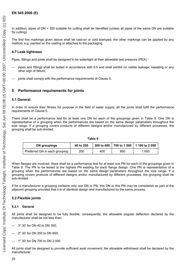
There shall be a performance test for at least one DN for each of the groupings given in Table 9. One DN is representative of a grouping when the performances are based on the same design parameters throughout the size range. If a grouping covers products of different designs and/or manufactured by different processes, the grouping shall be sub-divided.
Table 9
DN groupings 40 to 250 300 to 600 700 to 1 000 1 100 to 2 000
Preferred DN in each grouping 200 400 800 1 600
When flanges are involved, there shall be a performance test for at least one PN for each of the groupings given in Table 9. The PN to be tested is the highest PN existing for each flange design. One PN is representative of a grouping when the performances are based on the same design parameters throughout the size range. If a grouping covers products of different designs and/or manufactured by different processes, the grouping shall be sub-divided.
If for a manufacturer a grouping contains only one DN or PN, this DN or this PN may be considered as part of the adjacent grouping provided that it is of identical design and manufactured by the same process.
5.2 Flexible joints
5.2.1 General
All joints shall be designed to be fully flexible; consequently, the allowable angular deflection declared by the manufacturer shall be not less than:
3° 30’ for DN 40 to DN 300;
2° 30’ for DN 350 to DN 600;
1° 30’ for DN 700 to DN 2 000.
All joints shall be designed to provide sufficient axial movement; the allowable withdrawal shall be declared by the manufacturer. Li
cens
ed C
opy:
Inst
itute
Of T
echn
olog
y T
alla
ght,
Inst
itute
of T
echn
olog
y, S
at J
un 0
9 05
:08:
15 G
MT
+00
:00
2007
, Unc
ontr
olle
d C
opy,
(c)
BS
I
EN 545:2006 (E)
21
NOTE This permits the installed pipeline to accommodate ground movements and/or thermal effects without incurring additional stresses.
5.2.2 Test conditions
All joint designs shall be performance tested under the most unfavourable applicable conditions of tolerance and joint movement as given below:
a) joint of maximum annulus (see 5.2.3.1) aligned, withdrawn to the allowable value declared by the manufacturer, and subject to shear (see 5.2.3.3);
b) joint of maximum annulus (see 5.2.3.1) deflected to the allowable value declared by the manufacturer (see 5.2.1).
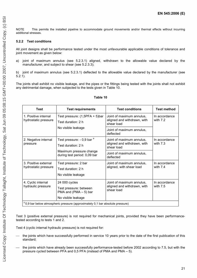
The joints shall exhibit no visible leakage, and the pipes or the fittings being tested with the joints shall not exhibit any detrimental damage, when subjected to the tests given in Table 10.
Table 10
Test Test requirements Test conditions Test method
Joint of maximum annulus, aligned and withdrawn, with shear load
1. Positive internal hydrostatic pressure
Test pressure: (1,5PFA + 5)bar
Test duration: 2 h
No visible leakage Joint of maximum annulus, deflected
In accordance with 7.2
Joint of maximum annulus, aligned and withdrawn, with shear load
2. Negative internal pressure
Test pressure: - 0,9 bar a
Test duration: 2 h
Maximum pressure change during test period: 0,09 bar Joint of maximum annulus,
deflected
In accordance with 7.3
3. Positive external hydrostatic pressure
Test pressure: 2 bar
Test duration: 2 h
No visible leakage
Joint of maximum annulus, aligned, with shear load
In accordance with 7.4
4. Cyclic internal hydraulic pressure
24 000 cycles
Test pressure: between PMA and (PMA – 5) bar
No visible leakage
Joint of maximum annulus, aligned and withdrawn, with shear load
In accordance with 7.5
a 0,9 bar below atmospheric pressure (approximately 0,1 bar absolute pressure)
Test 3 (positive external pressure) is not required for mechanical joints, provided they have been performance-tested according to tests 1 and 2.
Test 4 (cyclic internal hydraulic pressure) is not required for:
the joints which have successfully performed in service 10 years prior to the date of the first publication of this standard;
the joints which have already been successfully performance-tested before 2002 according to 7.5, but with the pressure cycled between PFA and 0,5 PFA (instead of PMA and PMA – 5).
Lice
nsed
Cop
y: In
stitu
te O
f Tec
hnol
ogy
Tal
lagh
t, In
stitu
te o
f Tec
hnol
ogy,
Sat
Jun
09
05:0
8:15
GM
T+
00:0
0 20
07, U
ncon
trol
led
Cop
y, (
c) B
SI
EN 545:2006 (E)
22
5.2.3 Test parameters
5.2.3.1 Annulus
All joints shall be performance tested at the extremes of manufacturing tolerance such that the annular gap between the sealing surfaces of the socket and of the spigot is equal to the maximum design value plus 0 %, minus 5 %. It is permissible to machine socket internal surfaces to achieve the required annulus for the performance-test even though the resultant diameter can be slightly outside the normal manufacturing tolerance.
5.2.3.2 Pipe thickness
All joints shall be performance tested with a spigot having an average iron wall thickness (over a distance of 2 DN, in millimetres, from the spigot end face) equal to the specified minimum value for the pipe for which the joint is designed plus 10 %, minus 0 %. It is permissible to machine the spigot end of the test pipe in the bore to achieve the required thickness.
5.2.3.3 Shear
All joints shall be performance tested with a resultant shear force across the joints of not less than 50 DN, in newtons, taking into account the weight of the pipe and of its contents and the geometry of the test assembly (see 7.2).
5.3 Restrained flexible joints
All restrained joints shall be designed to be at least semi-flexible; consequently, the allowable angular deflection declared by the manufacturer shall be not less than half the value shown in 5.2.1.
All restrained joint designs shall be performance-tested in accordance with 7.2 to 7.5 following the requirements of 5.2.2 and 5.2.3, except that:
the withdrawal condition of 5.2.2 a) shall not apply;
there shall be no external axial restraint in positive internal pressure tests so that the joint is subjected to the full end thrust.
During the positive internal pressure tests, the axial movement shall reach a stable value and cease.
When the restraining mechanism and the sealing component of a restrained joint are independent, such a joint does not need to be subjected to test 2 and test 3 of 5.2.2 if the unrestrained version of the joint has passed these tests.
5.4 Flanged joints
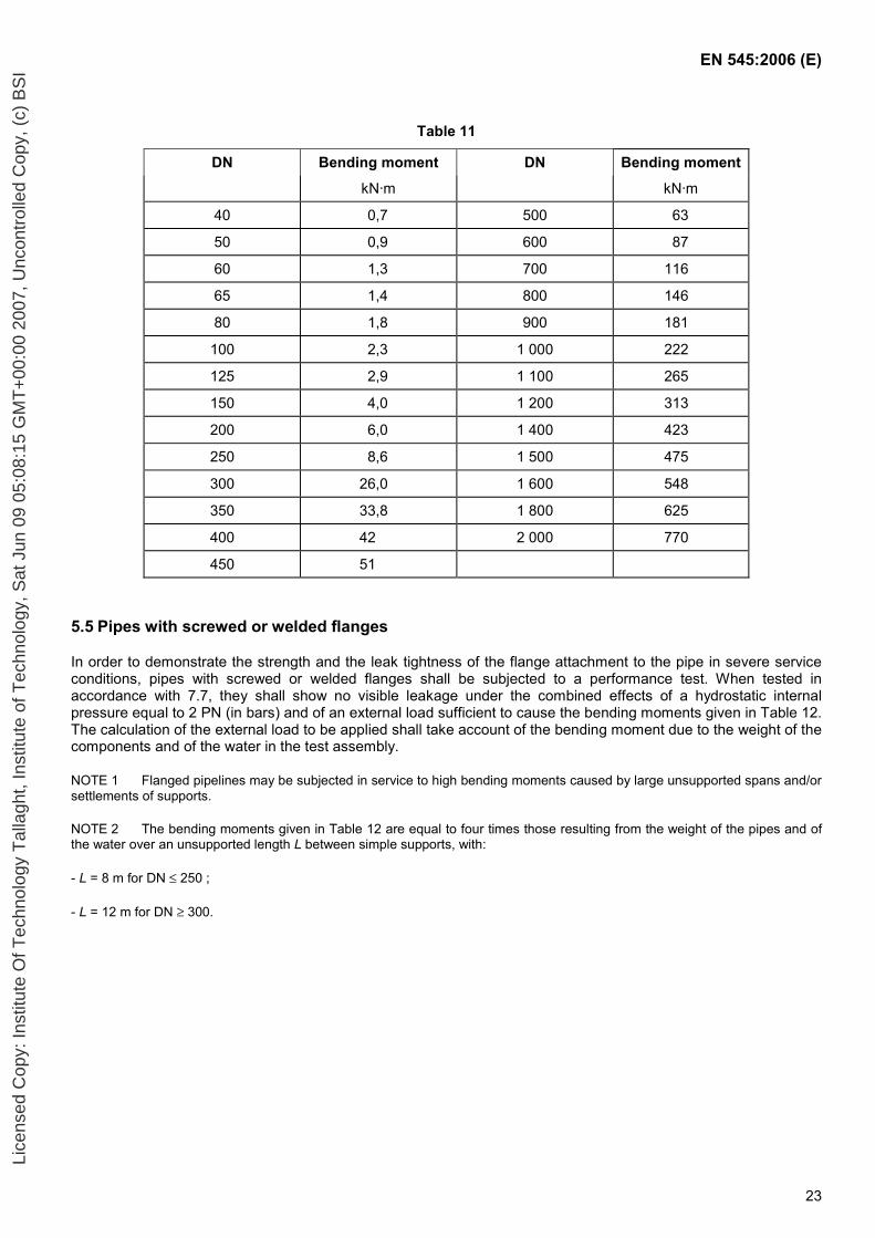
In order to demonstrate their strength and leak tightness in service conditions, flanged joints shall be subjected to a performance test. When tested in accordance with 7.6, they shall show no visible leakage under the combined effects of a hydrostatic internal pressure and of a bending moment given in Table 11, where:
the pressure is (1,5 PN + 5) bar;
the relevant bending moment is obtained by addition of the bending moments due to the weight of the components and of the water in the test assembly and to a possible external load calculated as a function of the length of the unsupported span of the testing arrangement (see 7.6).
NOTE The bending moments given in Table 11 are equal to those resulting from the weight of the pipes and of the water over an unsupported pipe length L between simple supports, with:
- L = 8 m for DN ≤ 250 ;
- L = 12 m for DN ≥ 300. Lice
nsed
Cop
y: In
stitu
te O
f Tec
hnol
ogy
Tal
lagh
t, In
stitu
te o
f Tec
hnol
ogy,
Sat
Jun
09
05:0
8:15
GM
T+
00:0
0 20
07, U
ncon
trol
led
Cop
y, (
c) B
SI
EN 545:2006 (E)
23
Table 11
DN Bending moment DN Bending moment
kN·m kN·m
40 0,7 500 63
50 0,9 600 87
60 1,3 700 116
65 1,4 800 146
80 1,8 900 181
100 2,3 1 000 222
125 2,9 1 100 265
150 4,0 1 200 313
200 6,0 1 400 423
250 8,6 1 500 475
300 26,0 1 600 548
350 33,8 1 800 625
400 42 2 000 770
450 51
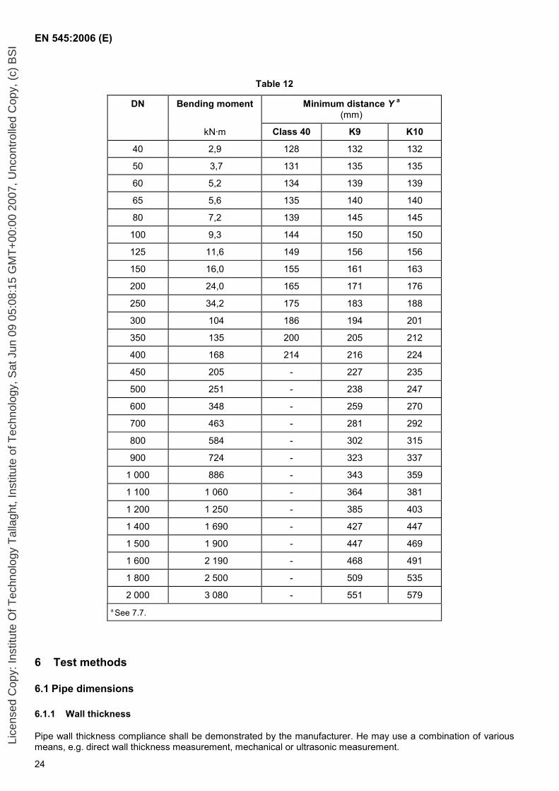
5.5 Pipes with screwed or welded flanges
In order to demonstrate the strength and the leak tightness of the flange attachment to the pipe in severe service conditions, pipes with screwed or welded flanges shall be subjected to a performance test. When tested in accordance with 7.7, they shall show no visible leakage under the combined effects of a hydrostatic internal pressure equal to 2 PN (in bars) and of an external load sufficient to cause the bending moments given in Table 12. The calculation of the external load to be applied shall take account of the bending moment due to the weight of the components and of the water in the test assembly.
NOTE 1 Flanged pipelines may be subjected in service to high bending moments caused by large unsupported spans and/or settlements of supports.
NOTE 2 The bending moments given in Table 12 are equal to four times those resulting from the weight of the pipes and of the water over an unsupported length L between simple supports, with:
- L = 8 m for DN ≤ 250 ;
- L = 12 m for DN ≥ 300.
Lice
nsed
Cop
y: In
stitu
te O
f Tec
hnol
ogy
Tal
lagh
t, In
stitu
te o
f Tec
hnol
ogy,
Sat
Jun
09
05:0
8:15
GM
T+
00:0
0 20
07, U
ncon
trol
led
Cop
y, (
c) B
SI
EN 545:2006 (E)
24
Table 12
DN Bending moment Minimum distance Y a (mm)
kN·m Class 40 K9 K10
40 2,9 128 132 132
50 3,7 131 135 135
60 5,2 134 139 139
65 5,6 135 140 140
80 7,2 139 145 145
100 9,3 144 150 150
125 11,6 149 156 156
150 16,0 155 161 163
200 24,0 165 171 176
250 34,2 175 183 188
300 104 186 194 201
350 135 200 205 212
400 168 214 216 224
450 205 - 227 235
500 251 - 238 247
600 348 - 259 270
700 463 - 281 292
800 584 - 302 315
900 724 - 323 337
1 000 886 - 343 359
1 100 1 060 - 364 381
1 200 1 250 - 385 403
1 400 1 690 - 427 447
1 500 1 900 - 447 469
1 600 2 190 - 468 491
1 800 2 500 - 509 535
2 000 3 080 - 551 579 a See 7.7.
6 Test methods
6.1 Pipe dimensions
6.1.1 Wall thickness
Pipe wall thickness compliance shall be demonstrated by the manufacturer. He may use a combination of various means, e.g. direct wall thickness measurement, mechanical or ultrasonic measurement. Li
cens
ed C
opy:
Inst
itute
Of T
echn
olog
y T
alla
ght,
Inst
itute
of T
echn
olog
y, S
at J
un 0
9 05
:08:
15 G
MT
+00
:00
2007
, Unc
ontr
olle
d C
opy,
(c)
BS
I
EN 545:2006 (E)
25
The iron wall thickness shall be measured by suitable equipment having an error limit ± 0,1mm.
6.1.2 External diameter
Socket and spigot pipes shall be measured at their spigot end by means of a circumferential tape or controlled by pass-fail gauges. In addition, they shall be visually inspected for compliance with the spigot allowable ovality and, in case of doubt, the maximum and minimum spigot axes shall be measured by suitable equipment or controlled by pass-fail gauges.
6.1.3 Internal diameter
The internal diameter of the lined pipes shall be measured by means of suitable equipment:
a) either two measurements shall be taken at right angles, at a cross section 200 mm or more from the end face. The mean value of these two measurements may then be calculated;
or
b) a system of pass / fail gauges shall be passed along the bore of the pipe.
6.1.4 Length
The length of socket and spigot pipes shall be measured by suitable equipment:
on one pipe from the first batch of pipes cast from a new mould, for as-cast pipes;
on the first pipe, for pipes which are systematically cut to a pre-set length.
6.2 Straightness of pipes
The pipe shall be rolled on two gantries or rotated around its axis on rollers, which in each case are separated by not less than two-thirds of the standardized pipe length.
The point of maximum deviation from the straight axis shall be determined and the deviation measured at that point.
6.3 Tensile testing
6.3.1 Samples
6.3.1.1 General
The thickness of the sample and the diameter of the test bar shall be as given in Table 13.
6.3.1.2 Centrifugally cast pipes
A sample shall be cut from the spigot end of the pipe. This sample may be cut parallel with or perpendicular to the pipe axis, but in case of dispute the parallel with axis sample shall be used.
6.3.1.3 Pipes not centrifugally cast, fittings and accessories
At the manufacturer’s option, samples shall be either cast integrally with the castings or cast separately. In the latter case they shall be cast from the same metal as that used for the castings. If the castings are subjected to heat treatment, the samples shall be subjected to the same heat treatment cycle.
Lice
nsed
Cop
y: In
stitu
te O
f Tec
hnol
ogy
Tal
lagh
t, In
stitu
te o
f Tec
hnol
ogy,
Sat
Jun
09
05:0
8:15
GM
T+
00:0
0 20
07, U
ncon
trol
led
Cop
y, (
c) B
SI
EN 545:2006 (E)
26
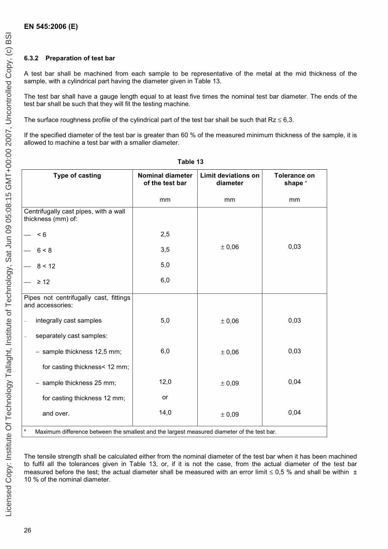
6.3.2 Preparation of test bar
A test bar shall be machined from each sample to be representative of the metal at the mid thickness of the sample, with a cylindrical part having the diameter given in Table 13.
The test bar shall have a gauge length equal to at least five times the nominal test bar diameter. The ends of the test bar shall be such that they will fit the testing machine.
The surface roughness profile of the cylindrical part of the test bar shall be such that Rz ≤ 6,3.
If the specified diameter of the test bar is greater than 60 % of the measured minimum thickness of the sample, it is allowed to machine a test bar with a smaller diameter.
Table 13
Nominal diameterof the test bar
Limit deviations on diameter
Tolerance on shape a
Type of casting
mm mm mm
Centrifugally cast pipes, with a wall thickness (mm) of:
< 6
6 < 8
8 < 12
≥ 12
2,5
3,5
5,0
6,0
± 0,06 0,03
Pipes not centrifugally cast, fittings and accessories:
– integrally cast samples
– separately cast samples:
− sample thickness 12,5 mm;
for casting thickness< 12 mm;
− sample thickness 25 mm;
for casting thickness 12 mm;
and over.
5,0
6,0
12,0
or
14,0
± 0,06
± 0,06
± 0,09
± 0,09
0,03
0,03
0,04
0,04
a Maximum difference between the smallest and the largest measured diameter of the test bar.
The tensile strength shall be calculated either from the nominal diameter of the test bar when it has been machined to fulfil all the tolerances given in Table 13, or, if it is not the case, from the actual diameter of the test bar measured before the test; the actual diameter shall be measured with an error limit ≤ 0,5 % and shall be within ± 10 % of the nominal diameter.
Lice
nsed
Cop
y: In
stitu
te O
f Tec
hnol
ogy
Tal
lagh
t, In
stitu
te o
f Tec
hnol
ogy,
Sat
Jun
09
05:0
8:15
GM
T+
00:0
0 20
07, U
ncon
trol
led
Cop
y, (
c) B
SI

EN 545:2006 (E)
27
6.3.3 Apparatus and test method
The tensile test shall be carried out in accordance to EN 10002-1.
6.3.4 Test results
Test results shall comply with Table 7. If they do not comply, the manufacturer shall:
a) in the case where the metal does not achieve the required mechanical properties, investigate the reason and ensure that all castings in the batch are either re-heat treated or rejected. Castings which have been re-heat treated are then re-tested in accordance with 6.3;
NOTE The manufacturer may limit the amount of rejection by making tests until the rejected batch of castings is bracketed, in order of manufacture, by a successful test at each end of the interval in question.
b) in the case of a defect in the test bar, carry out a further test. If it passes, the batch is accepted; if not, the manufacturer has the option to proceed as in a) above.
6.4 Brinell hardness
When Brinell hardness tests are carried out (see 4.3.2), they shall be performed either on the casting in dispute or on a sample cut from the casting. The surface to be tested shall be suitably prepared by slight local grinding and the test shall be carried out in accordance with EN ISO 6506-1 using a steel ball of 2,5 mm or 5 mm or 10 mm diameter.
6.5 Works leak tightness test for pipes and fittings
6.5.1 General
Pipes and fittings shall be tested in accordance with 6.5.2 and 6.5.3 respectively. The test shall be carried out on all pipes and fittings before the application of their external and internal coatings, except for the metallic zinc coating of pipes which may be applied before the test.
The test apparatus shall be suitable for applying the specified test pressures to the pipes and/or fittings. It shall be equipped with an industrial pressure gauge with an error limit ± 3%.
6.5.2 Centrifugally cast pipes
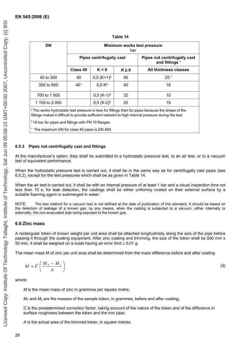
The internal hydrostatic pressure shall be raised steadily until it reaches the works hydrostatic test pressure given in Table 14, which is maintained for a sufficient time to allow visual inspection of the pipe barrel. The total duration of the pressure cycle shall be not less than 15 s, including 10 s at test pressure.
Lice
nsed
Cop
y: In
stitu
te O
f Tec
hnol
ogy
Tal
lagh
t, In
stitu
te o
f Tec
hnol
ogy,
Sat
Jun
09
05:0
8:15
GM
T+
00:0
0 20
07, U
ncon
trol
led
Cop
y, (
c) B
SI
EN 545:2006 (E)
28
Table 14
DN Minimum works test pressure bar
Pipes centrifugally cast Pipes not centrifugally cast and fittings a
Class 40 K < 9 K ≥≥≥≥ 9 All thickness classes
40 to 300 40 0,5 (K+1)² 50 25 b
350 to 600 40 c 0,5 K² 40 16
700 to 1 000 0,5 (K-1)² 32 10
1 100 to 2 000 0,5 (K-2)² 25 10 a The works hydrostatic test pressure is less for fittings than for pipes because the shape of the fittings makes it difficult to provide sufficient restraint to high internal pressure during the test. b 16 bar for pipes and fittings with PN 10 flanges. c The maximum DN for class 40 pipes is DN 400.
6.5.3 Pipes not centrifugally cast and fittings
At the manufacturer’s option, they shall be submitted to a hydrostatic pressure test, to an air test, or to a vacuum test of equivalent performance.
When the hydrostatic pressure test is carried out, it shall be in the same way as for centrifugally cast pipes (see 6.5.2), except for the test pressures which shall be as given in Table 14.
When the air test is carried out, it shall be with an internal pressure of at least 1 bar and a visual inspection time not less than 10 s; for leak detection, the castings shall be either uniformly coated on their external surface by a suitable foaming agent or submerged in water.
NOTE The test method for a vacuum test is not defined at the date of publication of this standard. It should be based on the detection of leakage of a known gas, by any means, when the casting is subjected to a vacuum, either internally or externally, the non-evacuated side being exposed to the known gas.
6.6 Zinc mass
A rectangular token of known weight per unit area shall be attached longitudinally along the axis of the pipe before passing it through the coating equipment. After zinc coating and trimming, the size of the token shall be 500 mm x 50 mm. It shall be weighed on a scale having an error limit ± 0,01 g.
The mean mass M of zinc per unit area shall be determined from the mass difference before and after coating.
−=
AMMCM 12 (3)
where:
M is the mean mass of zinc in grammes per square metre;
M1 and M2 are the masses of the sample token, in grammes, before and after coating;
C is the predetermined correction factor, taking account of the nature of the token and of the difference in surface roughness between the token and the iron pipe;
A is the actual area of the trimmed token, in square metres.
Lice
nsed
Cop
y: In
stitu
te O
f Tec
hnol
ogy
Tal
lagh
t, In
stitu
te o
f Tec
hnol
ogy,
Sat
Jun
09
05:0
8:15
GM
T+
00:0
0 20
07, U
ncon
trol
led
Cop
y, (
c) B
SI
EN 545:2006 (E)
29
NOTE The value of C, generally lying between 1 and 1,2, is given in the manufacturer’s quality assurance plan.
The uniformity of the coating shall be checked by visual inspection of the token; in the event of a lack of uniformity, 50 mm x 50 mm pieces shall be cut from the token in the lighter mass zones and the mean mass of zinc determined on each piece by mass difference.
Alternatively the mass of zinc per unit area can be measured directly on the coated pipe by any method having proven correlation with the reference method described above, e.g. X-ray fluorescence or chemical analysis.
6.7 Thickness of paint coatings
The dry film thickness of paint coatings shall be measured by either of the three following methods:
directly on the casting by means of suitable gauges, e.g. magnetic, or by using a ‘wet film’ thickness gauge where a correlation between wet film thickness and dry film thickness can be demonstrated;
indirectly on a token which is attached to the casting before coating and is used after coating to measure the dry film thickness by mechanical means, e.g. micrometer, or by a weight method similar to 6.6;
indirectly on a test plate made of steel or of ductile iron, which is coated by the same process as the castings to be controlled.
For each casting to be controlled, at least three measurements shall be taken (either on the casting or on the token or on a test plate). The mean thickness is the average of all the measurements taken and the local minimum thickness is the lowest value of all the measurements taken.
6.8 Thickness of cement mortar lining
During manufacture, the thickness shall be measured on the freshly applied lining by a spear having a diameter of 1,5 mm or less and controlled on the finished hardened lining by means of a suitable gauge, e.g. magnetic.
For pipes, the measurements shall be taken approximately 200 mm from the end face. The manufacturer’s process control system shall specify the frequency of this test.
7 Performance test methods
7.1 Compressive strength of the cement mortar lining
The compressive strength shall be the arithmetic mean of six compressive strength tests performed on three prism samples after 28 days of curing.
The compressive strength shall be determined by a performance-test in accordance with EN 196-1, except that:
the sand, the cement and the water used for the prism samples are identical with those used for the mortar before application of the lining;
the sand/cement ratio used for the prism samples is equal to that used for the mortar before application of the lining;
the water/cement ratio used for the prism samples is equal to that of the lining immediately after application to the pipe wall;
the test samples are prepared using either an impact table (in accordance with EN 196-1) or a vibrating table (2 min at 63 Hz) when the water/cement ratio is below 0,35.
NOTE This takes into account the influence of the centrifugal spinning process which allows expelling the excess water.
Lice
nsed
Cop
y: In
stitu
te O
f Tec
hnol
ogy
Tal
lagh
t, In
stitu
te o
f Tec
hnol
ogy,
Sat
Jun
09
05:0
8:15
GM
T+
00:0
0 20
07, U
ncon
trol
led
Cop
y, (
c) B
SI
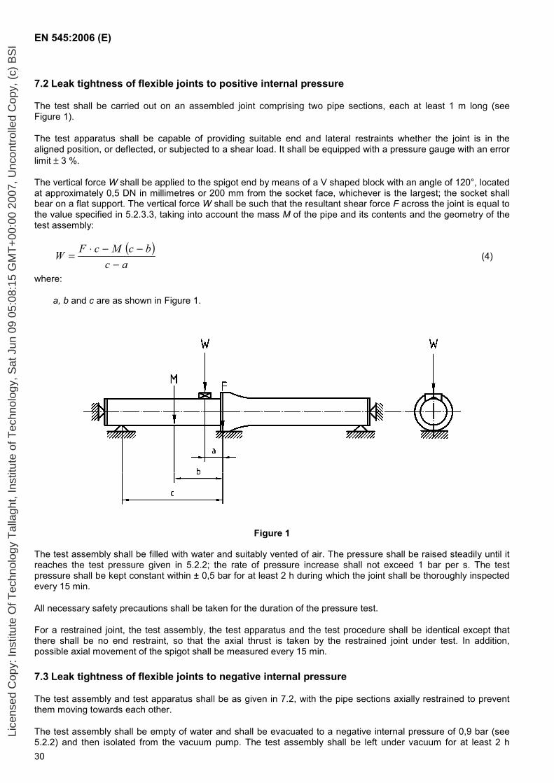
EN 545:2006 (E)
30
7.2 Leak tightness of flexible joints to positive internal pressure
The test shall be carried out on an assembled joint comprising two pipe sections, each at least 1 m long (see Figure 1).
The test apparatus shall be capable of providing suitable end and lateral restraints whether the joint is in the aligned position, or deflected, or subjected to a shear load. It shall be equipped with a pressure gauge with an error limit ± 3 %.
The vertical force W shall be applied to the spigot end by means of a V shaped block with an angle of 120°, located at approximately 0,5 DN in millimetres or 200 mm from the socket face, whichever is the largest; the socket shall bear on a flat support. The vertical force W shall be such that the resultant shear force F across the joint is equal to the value specified in 5.2.3.3, taking into account the mass M of the pipe and its contents and the geometry of the test assembly:
( )ac
bcMcFW−
−−⋅= (4)
where:
a, b and c are as shown in Figure 1.
Figure 1
The test assembly shall be filled with water and suitably vented of air. The pressure shall be raised steadily until it reaches the test pressure given in 5.2.2; the rate of pressure increase shall not exceed 1 bar per s. The test pressure shall be kept constant within ± 0,5 bar for at least 2 h during which the joint shall be thoroughly inspected every 15 min.
All necessary safety precautions shall be taken for the duration of the pressure test.
For a restrained joint, the test assembly, the test apparatus and the test procedure shall be identical except that there shall be no end restraint, so that the axial thrust is taken by the restrained joint under test. In addition, possible axial movement of the spigot shall be measured every 15 min.
7.3 Leak tightness of flexible joints to negative internal pressure
The test assembly and test apparatus shall be as given in 7.2, with the pipe sections axially restrained to prevent them moving towards each other.
The test assembly shall be empty of water and shall be evacuated to a negative internal pressure of 0,9 bar (see 5.2.2) and then isolated from the vacuum pump. The test assembly shall be left under vacuum for at least 2 h
Lice
nsed
Cop
y: In
stitu
te O
f Tec
hnol
ogy
Tal
lagh
t, In
stitu
te o
f Tec
hnol
ogy,
Sat
Jun
09
05:0
8:15
GM
T+
00:0
0 20
07, U
ncon
trol
led
Cop
y, (
c) B
SI
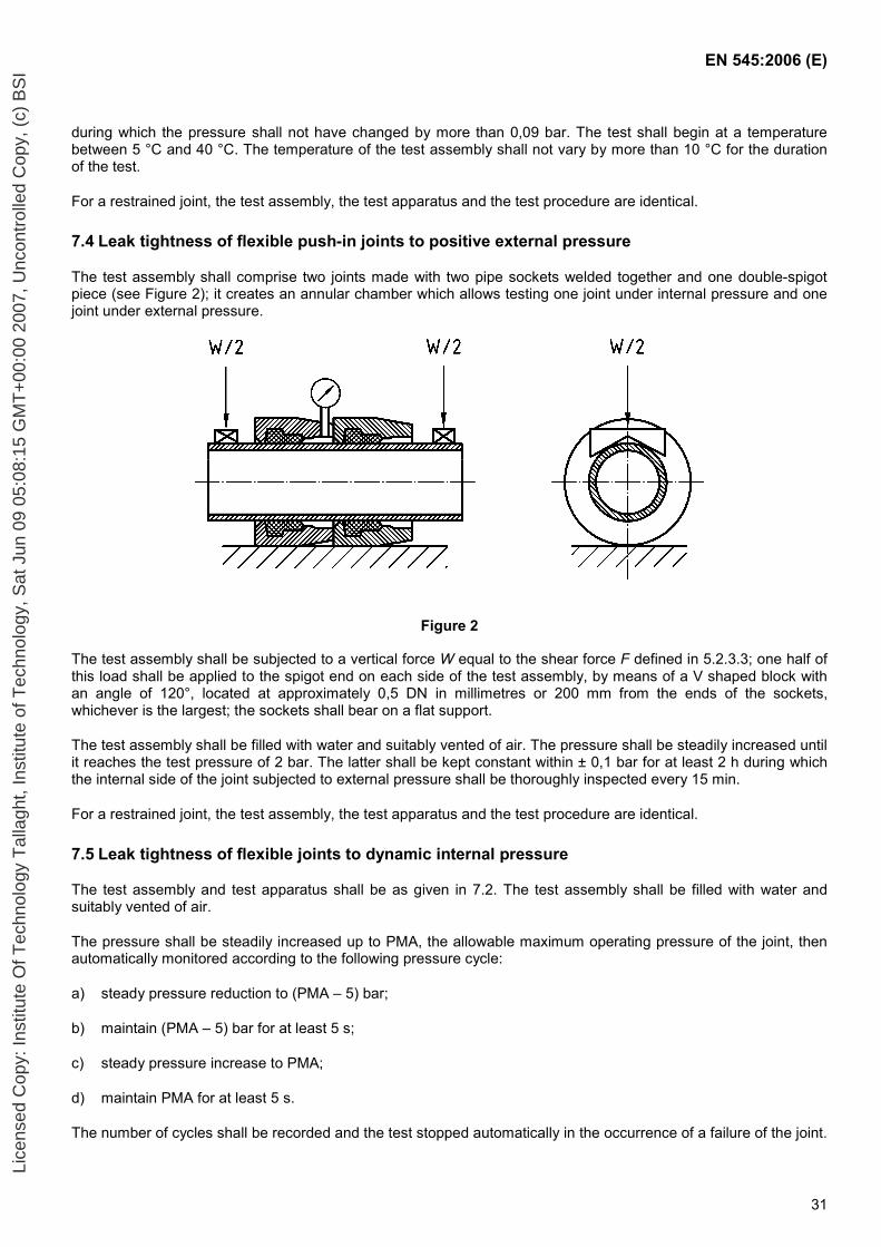
EN 545:2006 (E)
31
during which the pressure shall not have changed by more than 0,09 bar. The test shall begin at a temperature between 5 °C and 40 °C. The temperature of the test assembly shall not vary by more than 10 °C for the duration of the test.
For a restrained joint, the test assembly, the test apparatus and the test procedure are identical.
7.4 Leak tightness of flexible push-in joints to positive external pressure
The test assembly shall comprise two joints made with two pipe sockets welded together and one double-spigot piece (see Figure 2); it creates an annular chamber which allows testing one joint under internal pressure and one joint under external pressure.
Figure 2
The test assembly shall be subjected to a vertical force W equal to the shear force F defined in 5.2.3.3; one half of this load shall be applied to the spigot end on each side of the test assembly, by means of a V shaped block with an angle of 120°, located at approximately 0,5 DN in millimetres or 200 mm from the ends of the sockets, whichever is the largest; the sockets shall bear on a flat support.
The test assembly shall be filled with water and suitably vented of air. The pressure shall be steadily increased until it reaches the test pressure of 2 bar. The latter shall be kept constant within ± 0,1 bar for at least 2 h during which the internal side of the joint subjected to external pressure shall be thoroughly inspected every 15 min.
For a restrained joint, the test assembly, the test apparatus and the test procedure are identical.
7.5 Leak tightness of flexible joints to dynamic internal pressure
The test assembly and test apparatus shall be as given in 7.2. The test assembly shall be filled with water and suitably vented of air.
The pressure shall be steadily increased up to PMA, the allowable maximum operating pressure of the joint, then automatically monitored according to the following pressure cycle:
a) steady pressure reduction to (PMA – 5) bar;
b) maintain (PMA – 5) bar for at least 5 s;
c) steady pressure increase to PMA;
d) maintain PMA for at least 5 s.
The number of cycles shall be recorded and the test stopped automatically in the occurrence of a failure of the joint.
Lice
nsed
Cop
y: In
stitu
te O
f Tec
hnol
ogy
Tal
lagh
t, In
stitu
te o
f Tec
hnol
ogy,
Sat
Jun
09
05:0
8:15
GM
T+
00:0
0 20
07, U
ncon
trol
led
Cop
y, (
c) B
SI
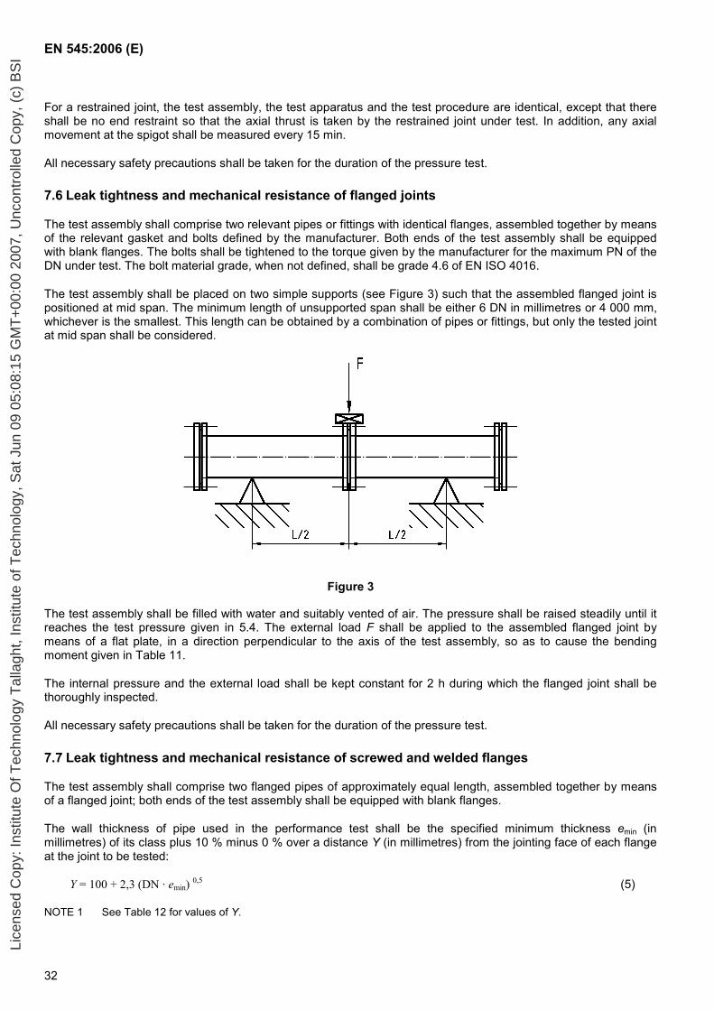
EN 545:2006 (E)
32
For a restrained joint, the test assembly, the test apparatus and the test procedure are identical, except that there shall be no end restraint so that the axial thrust is taken by the restrained joint under test. In addition, any axial movement at the spigot shall be measured every 15 min.
All necessary safety precautions shall be taken for the duration of the pressure test.
7.6 Leak tightness and mechanical resistance of flanged joints
The test assembly shall comprise two relevant pipes or fittings with identical flanges, assembled together by means of the relevant gasket and bolts defined by the manufacturer. Both ends of the test assembly shall be equipped with blank flanges. The bolts shall be tightened to the torque given by the manufacturer for the maximum PN of the DN under test. The bolt material grade, when not defined, shall be grade 4.6 of EN ISO 4016.
The test assembly shall be placed on two simple supports (see Figure 3) such that the assembled flanged joint is positioned at mid span. The minimum length of unsupported span shall be either 6 DN in millimetres or 4 000 mm, whichever is the smallest. This length can be obtained by a combination of pipes or fittings, but only the tested joint at mid span shall be considered.
Figure 3
The test assembly shall be filled with water and suitably vented of air. The pressure shall be raised steadily until it reaches the test pressure given in 5.4. The external load F shall be applied to the assembled flanged joint by means of a flat plate, in a direction perpendicular to the axis of the test assembly, so as to cause the bending moment given in Table 11.
The internal pressure and the external load shall be kept constant for 2 h during which the flanged joint shall be thoroughly inspected.
All necessary safety precautions shall be taken for the duration of the pressure test.
7.7 Leak tightness and mechanical resistance of screwed and welded flanges
The test assembly shall comprise two flanged pipes of approximately equal length, assembled together by means of a flanged joint; both ends of the test assembly shall be equipped with blank flanges.
The wall thickness of pipe used in the performance test shall be the specified minimum thickness emin (in millimetres) of its class plus 10 % minus 0 % over a distance Y (in millimetres) from the jointing face of each flange at the joint to be tested:
Y = 100 + 2,3 (DN · emin) 0,5 (5)
NOTE 1 See Table 12 for values of Y.
Lice
nsed
Cop
y: In
stitu
te O
f Tec
hnol
ogy
Tal
lagh
t, In
stitu
te o
f Tec
hnol
ogy,
Sat
Jun
09
05:0
8:15
GM
T+
00:0
0 20
07, U
ncon
trol
led
Cop
y, (
c) B
SI
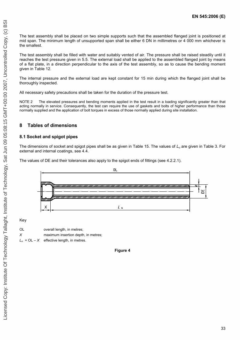
EN 545:2006 (E)
33
The test assembly shall be placed on two simple supports such that the assembled flanged joint is positioned at mid span. The minimum length of unsupported span shall be either 6 DN in millimetres or 4 000 mm whichever is the smallest.
The test assembly shall be filled with water and suitably vented of air. The pressure shall be raised steadily until it reaches the test pressure given in 5.5. The external load shall be applied to the assembled flanged joint by means of a flat plate, in a direction perpendicular to the axis of the test assembly, so as to cause the bending moment given in Table 12.
The internal pressure and the external load are kept constant for 15 min during which the flanged joint shall be thoroughly inspected.
All necessary safety precautions shall be taken for the duration of the pressure test.
NOTE 2 The elevated pressures and bending moments applied in the test result in a loading significantly greater than that acting normally in service. Consequently, the test can require the use of gaskets and bolts of higher performance than those normally supplied and the application of bolt torques in excess of those normally applied during site installation.
8 Tables of dimensions
8.1 Socket and spigot pipes
The dimensions of socket and spigot pipes shall be as given in Table 15. The values of Lu are given in Table 3. For external and internal coatings, see 4.4.
The values of DE and their tolerances also apply to the spigot ends of fittings (see 4.2.2.1).
Key
OL overall length, in metres; X maximum insertion depth, in metres; Lu = OL – X effective length, in metres.
Figure 4
Lice
nsed
Cop
y: In
stitu
te O
f Tec
hnol
ogy
Tal
lagh
t, In
stitu
te o
f Tec
hnol
ogy,
Sat
Jun
09
05:0
8:15
GM
T+
00:0
0 20
07, U
ncon
trol
led
Cop
y, (
c) B
SI
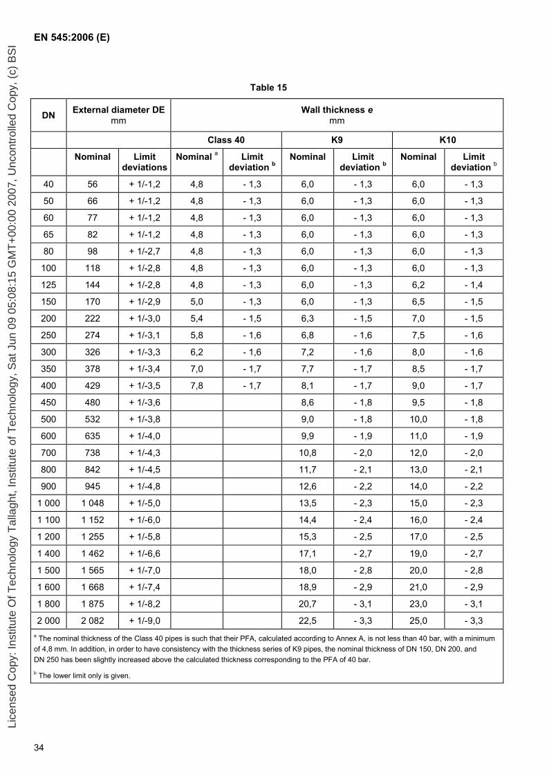
EN 545:2006 (E)
34
Table 15
DN External diameter DEmm
Wall thickness e mm
Class 40 K9 K10
Nominal Limit deviations
Nominal a Limit deviation b
Nominal Limit deviation b
Nominal Limit deviation b
40 56 + 1/-1,2 4,8 - 1,3 6,0 - 1,3 6,0 - 1,3
50 66 + 1/-1,2 4,8 - 1,3 6,0 - 1,3 6,0 - 1,3
60 77 + 1/-1,2 4,8 - 1,3 6,0 - 1,3 6,0 - 1,3
65 82 + 1/-1,2 4,8 - 1,3 6,0 - 1,3 6,0 - 1,3
80 98 + 1/-2,7 4,8 - 1,3 6,0 - 1,3 6,0 - 1,3
100 118 + 1/-2,8 4,8 - 1,3 6,0 - 1,3 6,0 - 1,3
125 144 + 1/-2,8 4,8 - 1,3 6,0 - 1,3 6,2 - 1,4
150 170 + 1/-2,9 5,0 - 1,3 6,0 - 1,3 6,5 - 1,5
200 222 + 1/-3,0 5,4 - 1,5 6,3 - 1,5 7,0 - 1,5
250 274 + 1/-3,1 5,8 - 1,6 6,8 - 1,6 7,5 - 1,6
300 326 + 1/-3,3 6,2 - 1,6 7,2 - 1,6 8,0 - 1,6
350 378 + 1/-3,4 7,0 - 1,7 7,7 - 1,7 8,5 - 1,7
400 429 + 1/-3,5 7,8 - 1,7 8,1 - 1,7 9,0 - 1,7
450 480 + 1/-3,6 8,6 - 1,8 9,5 - 1,8
500 532 + 1/-3,8 9,0 - 1,8 10,0 - 1,8
600 635 + 1/-4,0 9,9 - 1,9 11,0 - 1,9
700 738 + 1/-4,3 10,8 - 2,0 12,0 - 2,0
800 842 + 1/-4,5 11,7 - 2,1 13,0 - 2,1
900 945 + 1/-4,8 12,6 - 2,2 14,0 - 2,2
1 000 1 048 + 1/-5,0 13,5 - 2,3 15,0 - 2,3
1 100 1 152 + 1/-6,0 14,4 - 2,4 16,0 - 2,4
1 200 1 255 + 1/-5,8 15,3 - 2,5 17,0 - 2,5
1 400 1 462 + 1/-6,6 17,1 - 2,7 19,0 - 2,7
1 500 1 565 + 1/-7,0 18,0 - 2,8 20,0 - 2,8
1 600 1 668 + 1/-7,4 18,9 - 2,9 21,0 - 2,9
1 800 1 875 + 1/-8,2 20,7 - 3,1 23,0 - 3,1
2 000 2 082 + 1/-9,0 22,5 - 3,3 25,0 - 3,3 a The nominal thickness of the Class 40 pipes is such that their PFA, calculated according to Annex A, is not less than 40 bar, with a minimum of 4,8 mm. In addition, in order to have consistency with the thickness series of K9 pipes, the nominal thickness of DN 150, DN 200, and DN 250 has been slightly increased above the calculated thickness corresponding to the PFA of 40 bar.
b The lower limit only is given.
Lice
nsed
Cop
y: In
stitu
te O
f Tec
hnol
ogy
Tal
lagh
t, In
stitu
te o
f Tec
hnol
ogy,
Sat
Jun
09
05:0
8:15
GM
T+
00:0
0 20
07, U
ncon
trol
led
Cop
y, (
c) B
SI
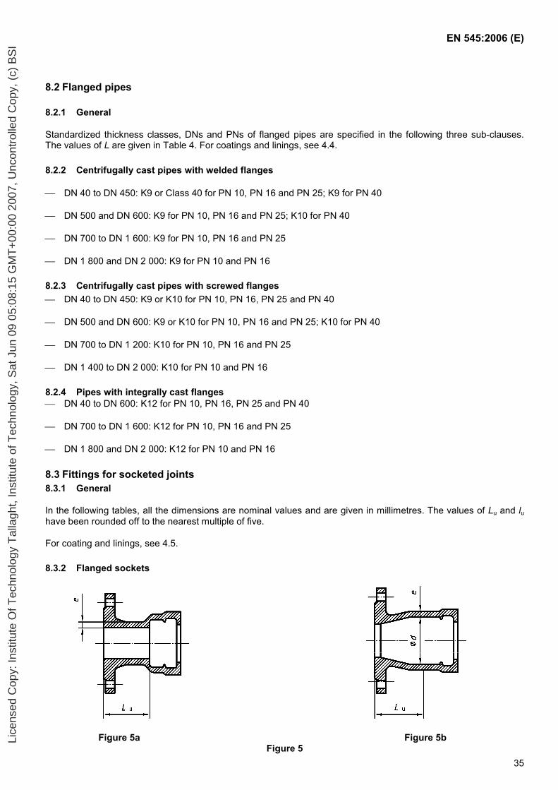
EN 545:2006 (E)
35
8.2 Flanged pipes
8.2.1 General
Standardized thickness classes, DNs and PNs of flanged pipes are specified in the following three sub-clauses. The values of L are given in Table 4. For coatings and linings, see 4.4.
8.2.2 Centrifugally cast pipes with welded flanges
DN 40 to DN 450: K9 or Class 40 for PN 10, PN 16 and PN 25; K9 for PN 40
DN 500 and DN 600: K9 for PN 10, PN 16 and PN 25; K10 for PN 40
DN 700 to DN 1 600: K9 for PN 10, PN 16 and PN 25
DN 1 800 and DN 2 000: K9 for PN 10 and PN 16
8.2.3 Centrifugally cast pipes with screwed flanges DN 40 to DN 450: K9 or K10 for PN 10, PN 16, PN 25 and PN 40
DN 500 and DN 600: K9 or K10 for PN 10, PN 16 and PN 25; K10 for PN 40
DN 700 to DN 1 200: K10 for PN 10, PN 16 and PN 25
DN 1 400 to DN 2 000: K10 for PN 10 and PN 16
8.2.4 Pipes with integrally cast flanges DN 40 to DN 600: K12 for PN 10, PN 16, PN 25 and PN 40
DN 700 to DN 1 600: K12 for PN 10, PN 16 and PN 25
DN 1 800 and DN 2 000: K12 for PN 10 and PN 16
8.3 Fittings for socketed joints 8.3.1 General
In the following tables, all the dimensions are nominal values and are given in millimetres. The values of Lu and lu have been rounded off to the nearest multiple of five.
For coating and linings, see 4.5.
8.3.2 Flanged sockets
Figure 5a Figure 5b Figure 5
Lice
nsed
Cop
y: In
stitu
te O
f Tec
hnol
ogy
Tal
lagh
t, In
stitu
te o
f Tec
hnol
ogy,
Sat
Jun
09
05:0
8:15
GM
T+
00:0
0 20
07, U
ncon
trol
led
Cop
y, (
c) B
SI
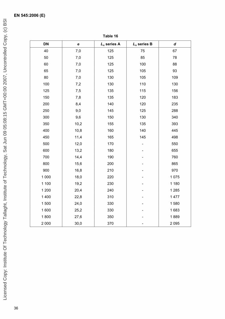
EN 545:2006 (E)
36
Table 16
DN e Lu series A Lu series B d
40 7,0 125 75 67
50 7,0 125 85 78
60 7,0 125 100 88
65 7,0 125 105 93
80 7,0 130 105 109
100 7,2 130 110 130
125 7,5 135 115 156
150 7,8 135 120 183
200 8,4 140 120 235
250 9,0 145 125 288
300 9,6 150 130 340
350 10,2 155 135 393
400 10,8 160 140 445
450 11,4 165 145 498
500 12,0 170 - 550
600 13,2 180 - 655
700 14,4 190 - 760
800 15,6 200 - 865
900 16,8 210 - 970
1 000 18,0 220 - 1 075
1 100 19,2 230 - 1 180
1 200 20,4 240 - 1 285
1 400 22,8 310 - 1 477
1 500 24,0 330 - 1 580
1 600 25,2 330 - 1 683
1 800 27,6 350 - 1 889
2 000 30,0 370 - 2 095
Lice
nsed
Cop
y: In
stitu
te O
f Tec
hnol
ogy
Tal
lagh
t, In
stitu
te o
f Tec
hnol
ogy,
Sat
Jun
09
05:0
8:15
GM
T+
00:0
0 20
07, U
ncon
trol
led
Cop
y, (
c) B
SI
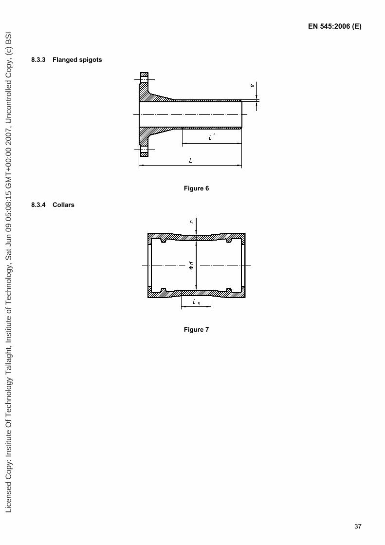
EN 545:2006 (E)
37
8.3.3 Flanged spigots
Figure 6
8.3.4 Collars
Figure 7
Lice
nsed
Cop
y: In
stitu
te O
f Tec
hnol
ogy
Tal
lagh
t, In
stitu
te o
f Tec
hnol
ogy,
Sat
Jun
09
05:0
8:15
GM
T+
00:0
0 20
07, U
ncon
trol
led
Cop
y, (
c) B
SI
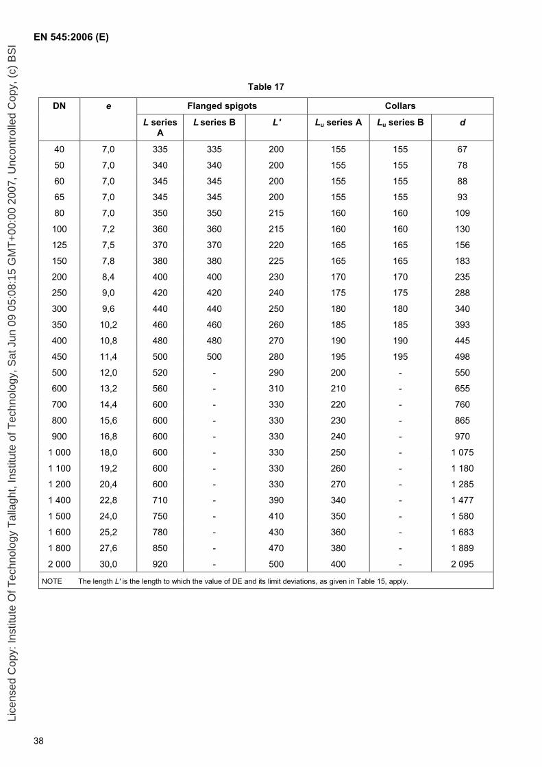
EN 545:2006 (E)
38
Table 17
DN e Flanged spigots Collars
L series A
L series B L' Lu series A Lu series B d
40 7,0 335 335 200 155 155 67
50 7,0 340 340 200 155 155 78
60 7,0 345 345 200 155 155 88
65 7,0 345 345 200 155 155 93
80 7,0 350 350 215 160 160 109
100 7,2 360 360 215 160 160 130
125 7,5 370 370 220 165 165 156
150 7,8 380 380 225 165 165 183
200 8,4 400 400 230 170 170 235
250 9,0 420 420 240 175 175 288
300 9,6 440 440 250 180 180 340
350 10,2 460 460 260 185 185 393
400 10,8 480 480 270 190 190 445
450 11,4 500 500 280 195 195 498
500 12,0 520 - 290 200 - 550
600 13,2 560 - 310 210 - 655
700 14,4 600 - 330 220 - 760
800 15,6 600 - 330 230 - 865
900 16,8 600 - 330 240 - 970
1 000 18,0 600 - 330 250 - 1 075
1 100 19,2 600 - 330 260 - 1 180
1 200 20,4 600 - 330 270 - 1 285
1 400 22,8 710 - 390 340 - 1 477
1 500 24,0 750 - 410 350 - 1 580
1 600 25,2 780 - 430 360 - 1 683
1 800 27,6 850 - 470 380 - 1 889
2 000 30,0 920 - 500 400 - 2 095
NOTE The length L' is the length to which the value of DE and its limit deviations, as given in Table 15, apply.
Lice
nsed
Cop
y: In
stitu
te O
f Tec
hnol
ogy
Tal
lagh
t, In
stitu
te o
f Tec
hnol
ogy,
Sat
Jun
09
05:0
8:15
GM
T+
00:0
0 20
07, U
ncon
trol
led
Cop
y, (
c) B
SI
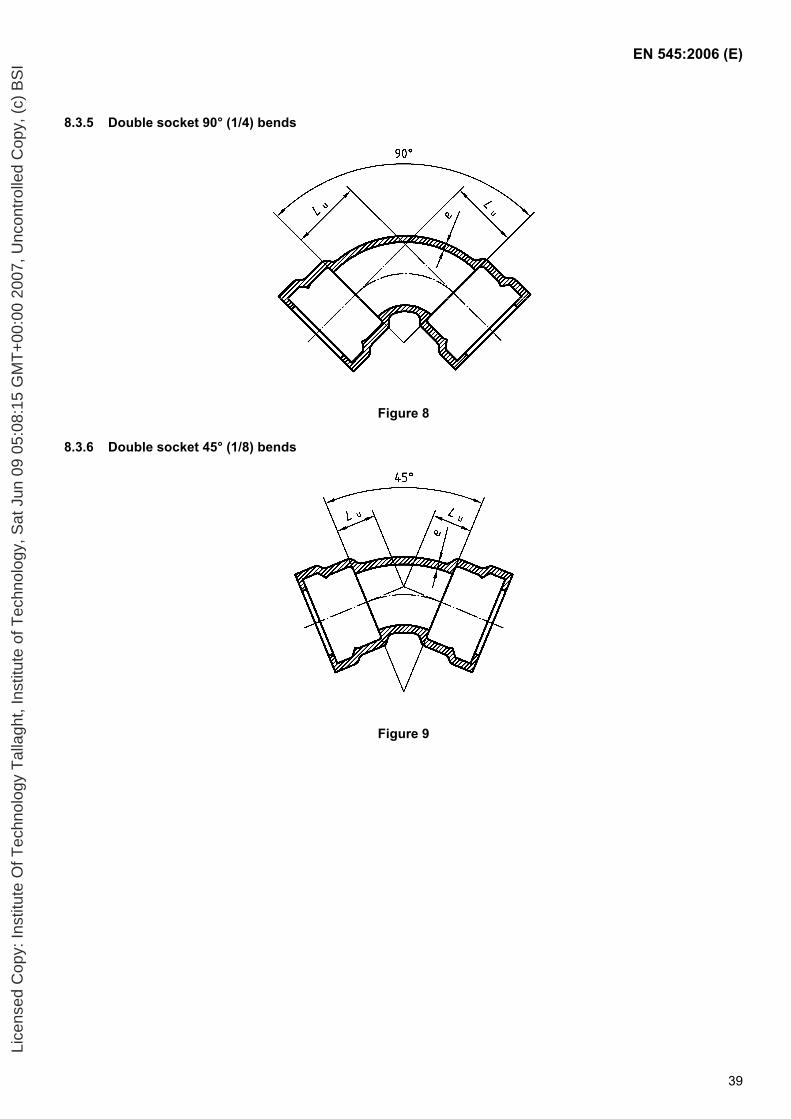
EN 545:2006 (E)
39
8.3.5 Double socket 90° (1/4) bends
Figure 8
8.3.6 Double socket 45° (1/8) bends
Figure 9
Lice
nsed
Cop
y: In
stitu
te O
f Tec
hnol
ogy
Tal
lagh
t, In
stitu
te o
f Tec
hnol
ogy,
Sat
Jun
09
05:0
8:15
GM
T+
00:0
0 20
07, U
ncon
trol
led
Cop
y, (
c) B
SI
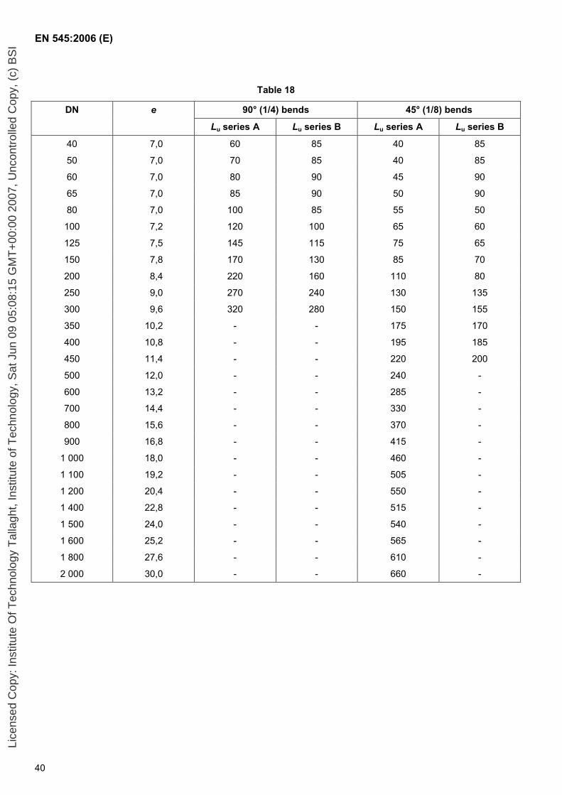
EN 545:2006 (E)
40
Table 18
DN e 90° (1/4) bends 45° (1/8) bends
Lu series A Lu series B Lu series A Lu series B
40 7,0 60 85 40 85
50 7,0 70 85 40 85
60 7,0 80 90 45 90
65 7,0 85 90 50 90
80 7,0 100 85 55 50
100 7,2 120 100 65 60
125 7,5 145 115 75 65
150 7,8 170 130 85 70
200 8,4 220 160 110 80
250 9,0 270 240 130 135
300 9,6 320 280 150 155
350 10,2 - - 175 170
400 10,8 - - 195 185
450 11,4 - - 220 200
500 12,0 - - 240 -
600 13,2 - - 285 -
700 14,4 - - 330 -
800 15,6 - - 370 -
900 16,8 - - 415 -
1 000 18,0 - - 460 -
1 100 19,2 - - 505 -
1 200 20,4 - - 550 -
1 400 22,8 - - 515 -
1 500 24,0 - - 540 -
1 600 25,2 - - 565 -
1 800 27,6 - - 610 -
2 000 30,0 - - 660 -
Lice
nsed
Cop
y: In
stitu
te O
f Tec
hnol
ogy
Tal
lagh
t, In
stitu
te o
f Tec
hnol
ogy,
Sat
Jun
09
05:0
8:15
GM
T+
00:0
0 20
07, U
ncon
trol
led
Cop
y, (
c) B
SI
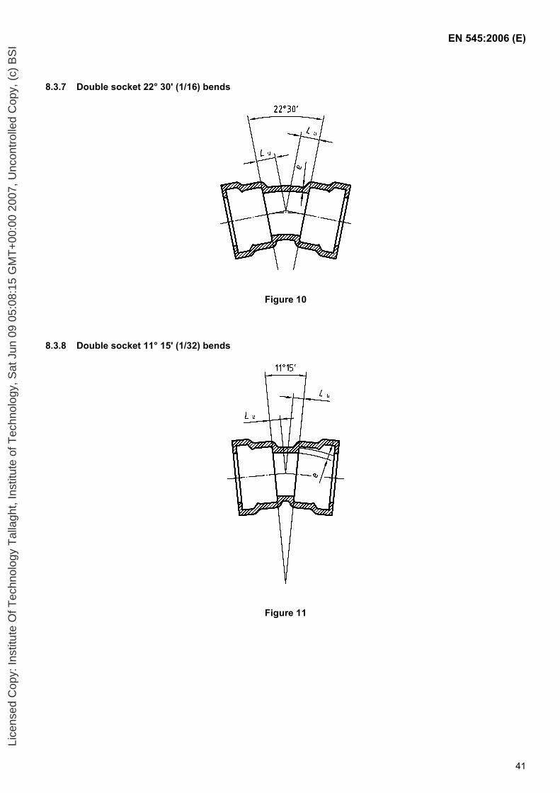
EN 545:2006 (E)
41
8.3.7 Double socket 22° 30' (1/16) bends
Figure 10
8.3.8 Double socket 11° 15' (1/32) bends
Figure 11
Lice
nsed
Cop
y: In
stitu
te O
f Tec
hnol
ogy
Tal
lagh
t, In
stitu
te o
f Tec
hnol
ogy,
Sat
Jun
09
05:0
8:15
GM
T+
00:0
0 20
07, U
ncon
trol
led
Cop
y, (
c) B
SI
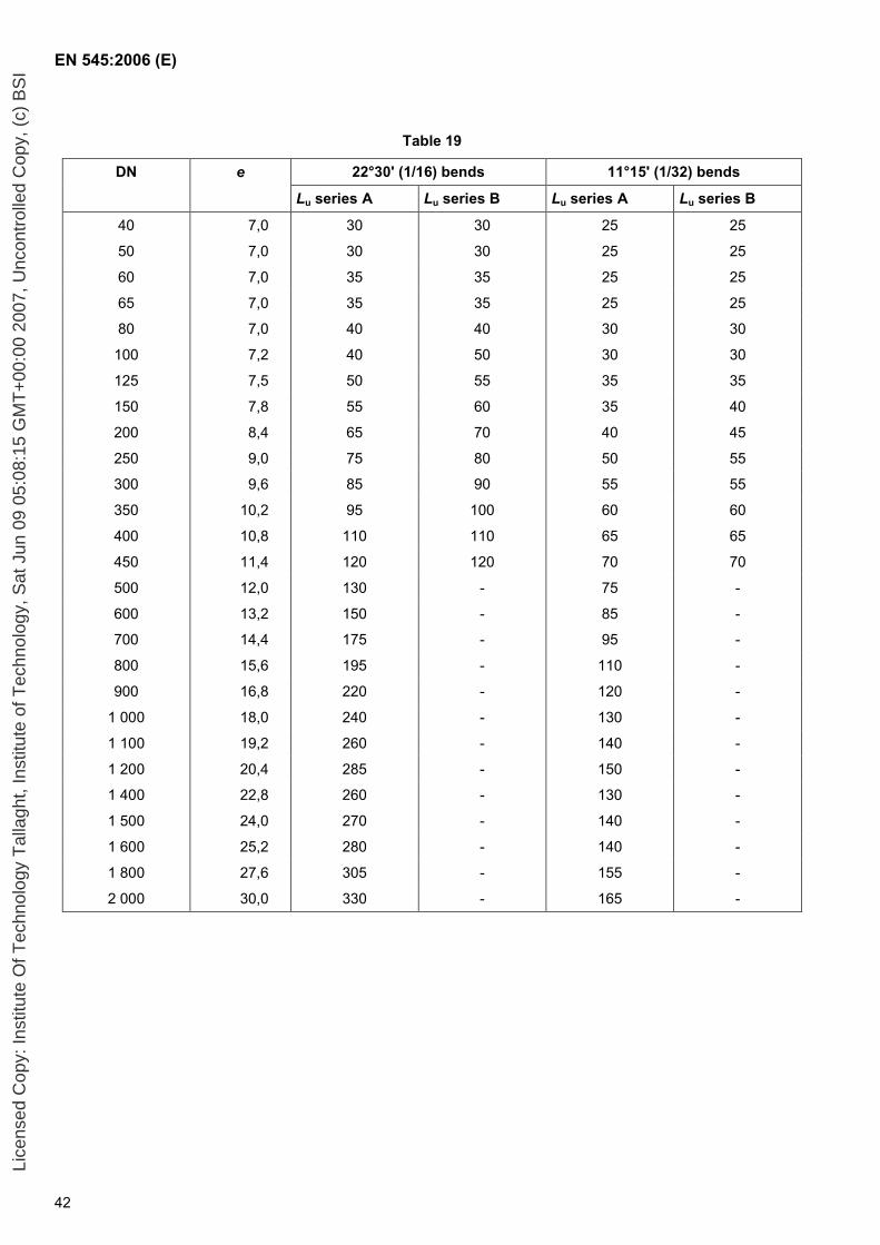
EN 545:2006 (E)
42
Table 19
DN e 22°30' (1/16) bends 11°15' (1/32) bends
Lu series A Lu series B Lu series A Lu series B
40 7,0 30 30 25 25
50 7,0 30 30 25 25
60 7,0 35 35 25 25
65 7,0 35 35 25 25
80 7,0 40 40 30 30
100 7,2 40 50 30 30
125 7,5 50 55 35 35
150 7,8 55 60 35 40
200 8,4 65 70 40 45
250 9,0 75 80 50 55
300 9,6 85 90 55 55
350 10,2 95 100 60 60
400 10,8 110 110 65 65
450 11,4 120 120 70 70
500 12,0 130 - 75 -
600 13,2 150 - 85 -
700 14,4 175 - 95 -
800 15,6 195 - 110 -
900 16,8 220 - 120 -
1 000 18,0 240 - 130 -
1 100 19,2 260 - 140 -
1 200 20,4 285 - 150 -
1 400 22,8 260 - 130 -
1 500 24,0 270 - 140 -
1 600 25,2 280 - 140 -
1 800 27,6 305 - 155 -
2 000 30,0 330 - 165 -
Lice
nsed
Cop
y: In
stitu
te O
f Tec
hnol
ogy
Tal
lagh
t, In
stitu
te o
f Tec
hnol
ogy,
Sat
Jun
09
05:0
8:15
GM
T+
00:0
0 20
07, U
ncon
trol
led
Cop
y, (
c) B
SI
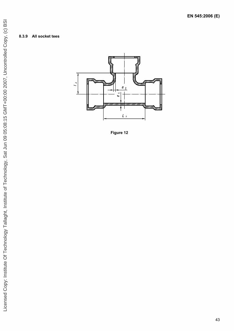
EN 545:2006 (E)
43
8.3.9 All socket tees
Figure 12
Lice
nsed
Cop
y: In
stitu
te O
f Tec
hnol
ogy
Tal
lagh
t, In
stitu
te o
f Tec
hnol
ogy,
Sat
Jun
09
05:0
8:15
GM
T+
00:0
0 20
07, U
ncon
trol
led
Cop
y, (
c) B
SI
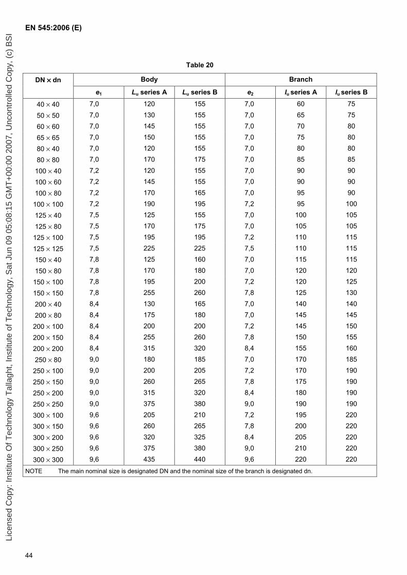
EN 545:2006 (E)
44
Table 20
DN ×××× dn Body Branch
e1 Lu series A Lu series B e2 lu series A lu series B
40 × 40 7,0 120 155 7,0 60 75
50 × 50 7,0 130 155 7,0 65 75
60 × 60 7,0 145 155 7,0 70 80
65 × 65 7,0 150 155 7,0 75 80
80 × 40 7,0 120 155 7,0 80 80
80 × 80 7,0 170 175 7,0 85 85
100 × 40 7,2 120 155 7,0 90 90
100 × 60 7,2 145 155 7,0 90 90
100 × 80 7,2 170 165 7,0 95 90
100 × 100 7,2 190 195 7,2 95 100
125 × 40 7,5 125 155 7,0 100 105
125 × 80 7,5 170 175 7,0 105 105
125 × 100 7,5 195 195 7,2 110 115
125 × 125 7,5 225 225 7,5 110 115
150 × 40 7,8 125 160 7,0 115 115
150 × 80 7,8 170 180 7,0 120 120
150 × 100 7,8 195 200 7,2 120 125
150 × 150 7,8 255 260 7,8 125 130
200 × 40 8,4 130 165 7,0 140 140
200 × 80 8,4 175 180 7,0 145 145
200 × 100 8,4 200 200 7,2 145 150
200 × 150 8,4 255 260 7,8 150 155
200 × 200 8,4 315 320 8,4 155 160
250 × 80 9,0 180 185 7,0 170 185
250 × 100 9,0 200 205 7,2 170 190
250 × 150 9,0 260 265 7,8 175 190
250 × 200 9,0 315 320 8,4 180 190
250 × 250 9,0 375 380 9,0 190 190
300 × 100 9,6 205 210 7,2 195 220
300 × 150 9,6 260 265 7,8 200 220
300 × 200 9,6 320 325 8,4 205 220
300 × 250 9,6 375 380 9,0 210 220
300 × 300 9,6 435 440 9,6 220 220
NOTE The main nominal size is designated DN and the nominal size of the branch is designated dn.
Lice
nsed
Cop
y: In
stitu
te O
f Tec
hnol
ogy
Tal
lagh
t, In
stitu
te o
f Tec
hnol
ogy,
Sat
Jun
09
05:0
8:15
GM
T+
00:0
0 20
07, U
ncon
trol
led
Cop
y, (
c) B
SI
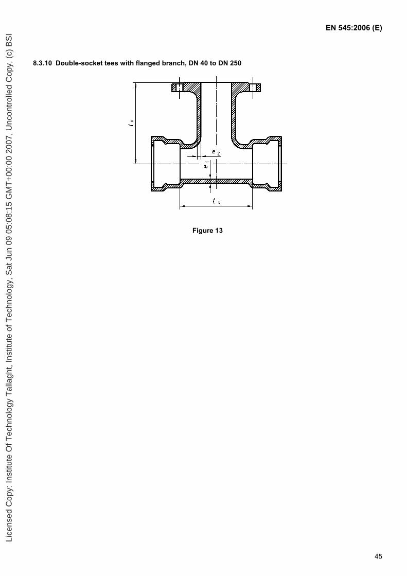
EN 545:2006 (E)
45
8.3.10 Double-socket tees with flanged branch, DN 40 to DN 250
Figure 13
Lice
nsed
Cop
y: In
stitu
te O
f Tec
hnol
ogy
Tal
lagh
t, In
stitu
te o
f Tec
hnol
ogy,
Sat
Jun
09
05:0
8:15
GM
T+
00:0
0 20
07, U
ncon
trol
led
Cop
y, (
c) B
SI
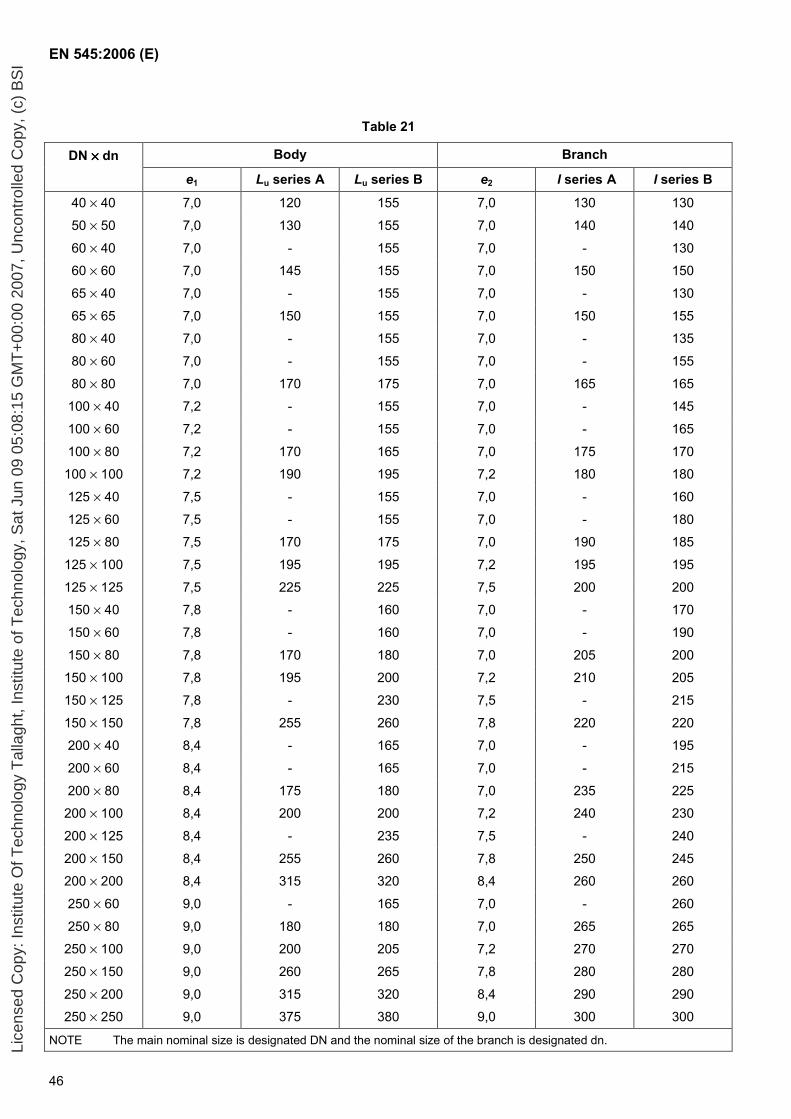
EN 545:2006 (E)
46
Table 21
DN ×××× dn Body Branch
e1 Lu series A Lu series B e2 l series A l series B
40 × 40 7,0 120 155 7,0 130 130
50 × 50 7,0 130 155 7,0 140 140
60 × 40 7,0 - 155 7,0 - 130
60 × 60 7,0 145 155 7,0 150 150
65 × 40 7,0 - 155 7,0 - 130
65 × 65 7,0 150 155 7,0 150 155
80 × 40 7,0 - 155 7,0 - 135
80 × 60 7,0 - 155 7,0 - 155
80 × 80 7,0 170 175 7,0 165 165
100 × 40 7,2 - 155 7,0 - 145
100 × 60 7,2 - 155 7,0 - 165
100 × 80 7,2 170 165 7,0 175 170
100 × 100 7,2 190 195 7,2 180 180
125 × 40 7,5 - 155 7,0 - 160
125 × 60 7,5 - 155 7,0 - 180
125 × 80 7,5 170 175 7,0 190 185
125 × 100 7,5 195 195 7,2 195 195
125 × 125 7,5 225 225 7,5 200 200
150 × 40 7,8 - 160 7,0 - 170
150 × 60 7,8 - 160 7,0 - 190
150 × 80 7,8 170 180 7,0 205 200
150 × 100 7,8 195 200 7,2 210 205
150 × 125 7,8 - 230 7,5 - 215
150 × 150 7,8 255 260 7,8 220 220
200 × 40 8,4 - 165 7,0 - 195
200 × 60 8,4 - 165 7,0 - 215
200 × 80 8,4 175 180 7,0 235 225
200 × 100 8,4 200 200 7,2 240 230
200 × 125 8,4 - 235 7,5 - 240
200 × 150 8,4 255 260 7,8 250 245
200 × 200 8,4 315 320 8,4 260 260
250 × 60 9,0 - 165 7,0 - 260
250 × 80 9,0 180 180 7,0 265 265
250 × 100 9,0 200 205 7,2 270 270
250 × 150 9,0 260 265 7,8 280 280
250 × 200 9,0 315 320 8,4 290 290
250 × 250 9,0 375 380 9,0 300 300
NOTE The main nominal size is designated DN and the nominal size of the branch is designated dn. Lice
nsed
Cop
y: In
stitu
te O
f Tec
hnol
ogy
Tal
lagh
t, In
stitu
te o
f Tec
hnol
ogy,
Sat
Jun
09
05:0
8:15
GM
T+
00:0
0 20
07, U
ncon
trol
led
Cop
y, (
c) B
SI
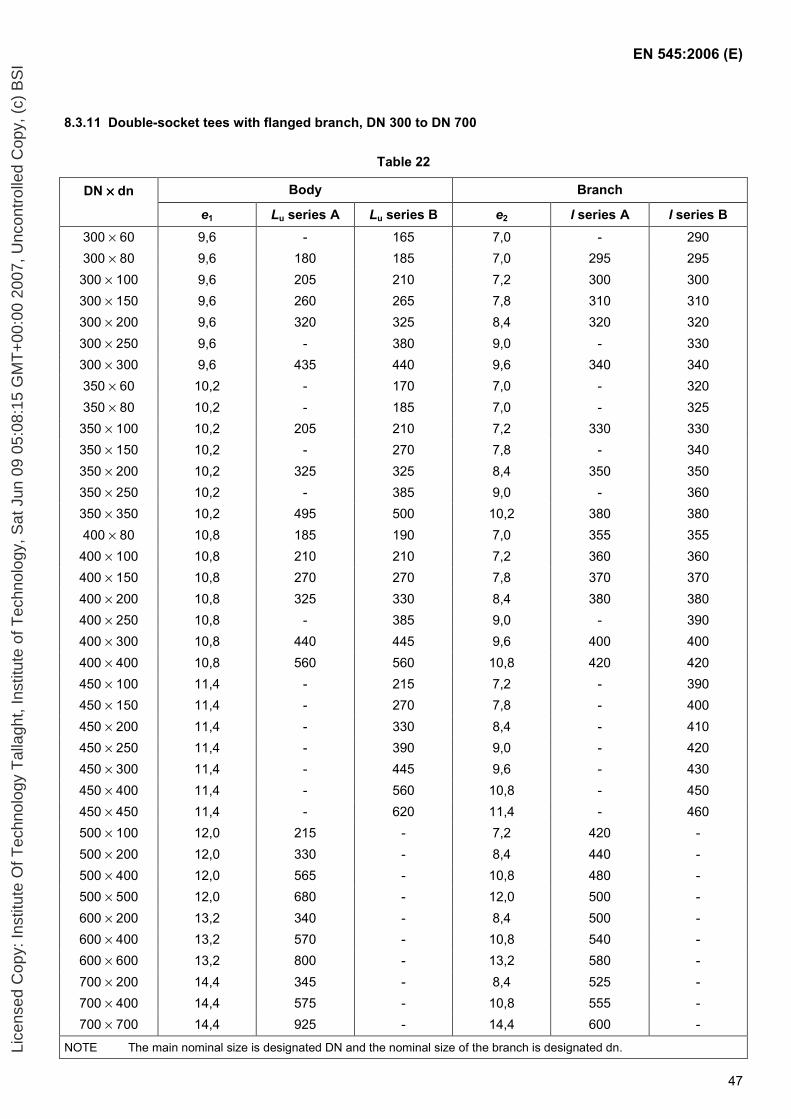
EN 545:2006 (E)
47
8.3.11 Double-socket tees with flanged branch, DN 300 to DN 700
Table 22
DN ×××× dn Body Branch
e1 Lu series A Lu series B e2 l series A l series B 300 × 60 9,6 - 165 7,0 - 290 300 × 80 9,6 180 185 7,0 295 295 300 × 100 9,6 205 210 7,2 300 300 300 × 150 9,6 260 265 7,8 310 310 300 × 200 9,6 320 325 8,4 320 320 300 × 250 9,6 - 380 9,0 - 330 300 × 300 9,6 435 440 9,6 340 340 350 × 60 10,2 - 170 7,0 - 320 350 × 80 10,2 - 185 7,0 - 325 350 × 100 10,2 205 210 7,2 330 330 350 × 150 10,2 - 270 7,8 - 340 350 × 200 10,2 325 325 8,4 350 350 350 × 250 10,2 - 385 9,0 - 360 350 × 350 10,2 495 500 10,2 380 380 400 × 80 10,8 185 190 7,0 355 355 400 × 100 10,8 210 210 7,2 360 360 400 × 150 10,8 270 270 7,8 370 370 400 × 200 10,8 325 330 8,4 380 380 400 × 250 10,8 - 385 9,0 - 390 400 × 300 10,8 440 445 9,6 400 400 400 × 400 10,8 560 560 10,8 420 420 450 × 100 11,4 - 215 7,2 - 390 450 × 150 11,4 - 270 7,8 - 400 450 × 200 11,4 - 330 8,4 - 410 450 × 250 11,4 - 390 9,0 - 420 450 × 300 11,4 - 445 9,6 - 430 450 × 400 11,4 - 560 10,8 - 450 450 × 450 11,4 - 620 11,4 - 460 500 × 100 12,0 215 - 7,2 420 - 500 × 200 12,0 330 - 8,4 440 - 500 × 400 12,0 565 - 10,8 480 - 500 × 500 12,0 680 - 12,0 500 - 600 × 200 13,2 340 - 8,4 500 - 600 × 400 13,2 570 - 10,8 540 - 600 × 600 13,2 800 - 13,2 580 - 700 × 200 14,4 345 - 8,4 525 - 700 × 400 14,4 575 - 10,8 555 - 700 × 700 14,4 925 - 14,4 600 -
NOTE The main nominal size is designated DN and the nominal size of the branch is designated dn. Lice
nsed
Cop
y: In
stitu
te O
f Tec
hnol
ogy
Tal
lagh
t, In
stitu
te o
f Tec
hnol
ogy,
Sat
Jun
09
05:0
8:15
GM
T+
00:0
0 20
07, U
ncon
trol
led
Cop
y, (
c) B
SI
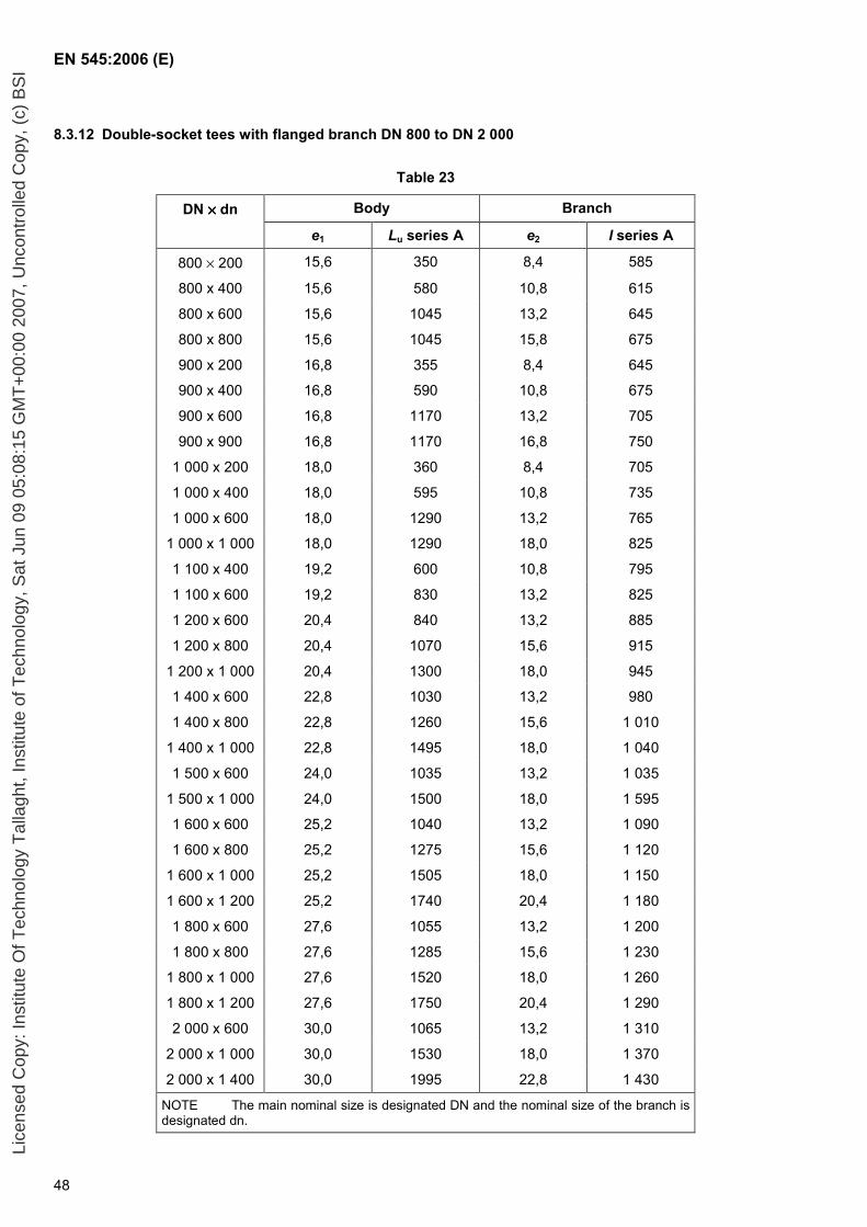
EN 545:2006 (E)
48
8.3.12 Double-socket tees with flanged branch DN 800 to DN 2 000
Table 23
DN ×××× dn Body Branch
e1 Lu series A e2 l series A
800 × 200 15,6 350 8,4 585
800 x 400 15,6 580 10,8 615
800 x 600 15,6 1045 13,2 645
800 x 800 15,6 1045 15,8 675
900 x 200 16,8 355 8,4 645
900 x 400 16,8 590 10,8 675
900 x 600 16,8 1170 13,2 705
900 x 900 16,8 1170 16,8 750
1 000 x 200 18,0 360 8,4 705
1 000 x 400 18,0 595 10,8 735
1 000 x 600 18,0 1290 13,2 765
1 000 x 1 000 18,0 1290 18,0 825
1 100 x 400 19,2 600 10,8 795
1 100 x 600 19,2 830 13,2 825
1 200 x 600 20,4 840 13,2 885
1 200 x 800 20,4 1070 15,6 915
1 200 x 1 000 20,4 1300 18,0 945
1 400 x 600 22,8 1030 13,2 980
1 400 x 800 22,8 1260 15,6 1 010
1 400 x 1 000 22,8 1495 18,0 1 040
1 500 x 600 24,0 1035 13,2 1 035
1 500 x 1 000 24,0 1500 18,0 1 595
1 600 x 600 25,2 1040 13,2 1 090
1 600 x 800 25,2 1275 15,6 1 120
1 600 x 1 000 25,2 1505 18,0 1 150
1 600 x 1 200 25,2 1740 20,4 1 180
1 800 x 600 27,6 1055 13,2 1 200
1 800 x 800 27,6 1285 15,6 1 230
1 800 x 1 000 27,6 1520 18,0 1 260
1 800 x 1 200 27,6 1750 20,4 1 290
2 000 x 600 30,0 1065 13,2 1 310
2 000 x 1 000 30,0 1530 18,0 1 370
2 000 x 1 400 30,0 1995 22,8 1 430
NOTE The main nominal size is designated DN and the nominal size of the branch is designated dn.
Lice
nsed
Cop
y: In
stitu
te O
f Tec
hnol
ogy
Tal
lagh
t, In
stitu
te o
f Tec
hnol
ogy,
Sat
Jun
09
05:0
8:15
GM
T+
00:0
0 20
07, U
ncon
trol
led
Cop
y, (
c) B
SI
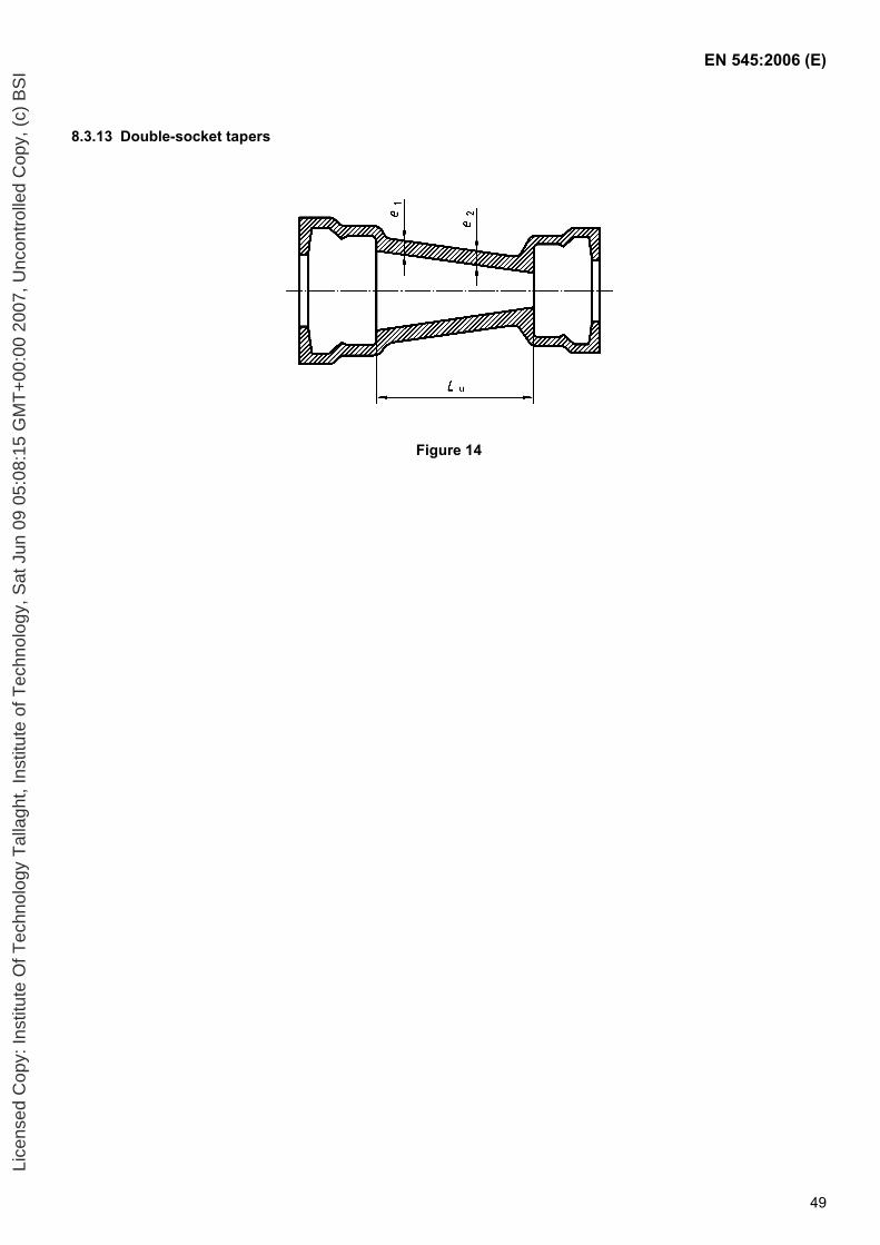
EN 545:2006 (E)
49
8.3.13 Double-socket tapers
Figure 14
Lice
nsed
Cop
y: In
stitu
te O
f Tec
hnol
ogy
Tal
lagh
t, In
stitu
te o
f Tec
hnol
ogy,
Sat
Jun
09
05:0
8:15
GM
T+
00:0
0 20
07, U
ncon
trol
led
Cop
y, (
c) B
SI
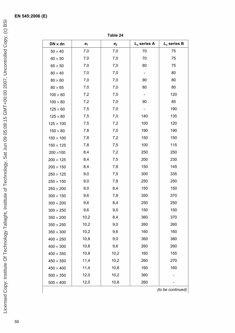
EN 545:2006 (E)
50
Table 24
DN ×××× dn e1 e2 Lu series A Lu series B
50 × 40 7,0 7,0 70 75
60 × 50 7,0 7,0 70 75
65 × 50 7,0 7,0 80 75
80 × 40 7,0 7,0 - 80
80 × 60 7,0 7,0 90 80
80 × 65 7,0 7,0 80 80
100 × 60 7,2 7,0 - 120
100 × 80 7,2 7,0 90 85
125 × 60 7,5 7,0 - 190
125 × 80 7,5 7,0 140 135
125 × 100 7,5 7,2 100 120
150 × 80 7,8 7,0 190 190
150 × 100 7,8 7,2 150 150
150 × 125 7,8 7,5 100 115
200 ×100 8,4 7,2 250 250
200 × 125 8,4 7,5 200 230
200 × 150 8,4 7,8 150 145
250 × 125 9,0 7,5 300 335
250 × 150 9,0 7,8 250 250
250 × 200 9,0 8,4 150 150
300 × 150 9,6 7,8 350 370
300 × 200 9,6 8,4 250 250
300 × 250 9,6 9,0 150 150
350 × 200 10,2 8,4 360 370
350 × 250 10,2 9,0 260 260
350 × 300 10,2 9,6 160 160
400 × 250 10,8 9,0 360 380
400 × 300 10,8 9,6 260 260
400 × 350 10,8 10,2 160 155
450 × 350 11,4 10,2 260 270
450 × 400 11,4 10,8 160 160
500 × 350 12,0 10,2 360 -
500 × 400 12,0 10,8 260 -
(to be continued)
Lice
nsed
Cop
y: In
stitu
te O
f Tec
hnol
ogy
Tal
lagh
t, In
stitu
te o
f Tec
hnol
ogy,
Sat
Jun
09
05:0
8:15
GM
T+
00:0
0 20
07, U
ncon
trol
led
Cop
y, (
c) B
SI
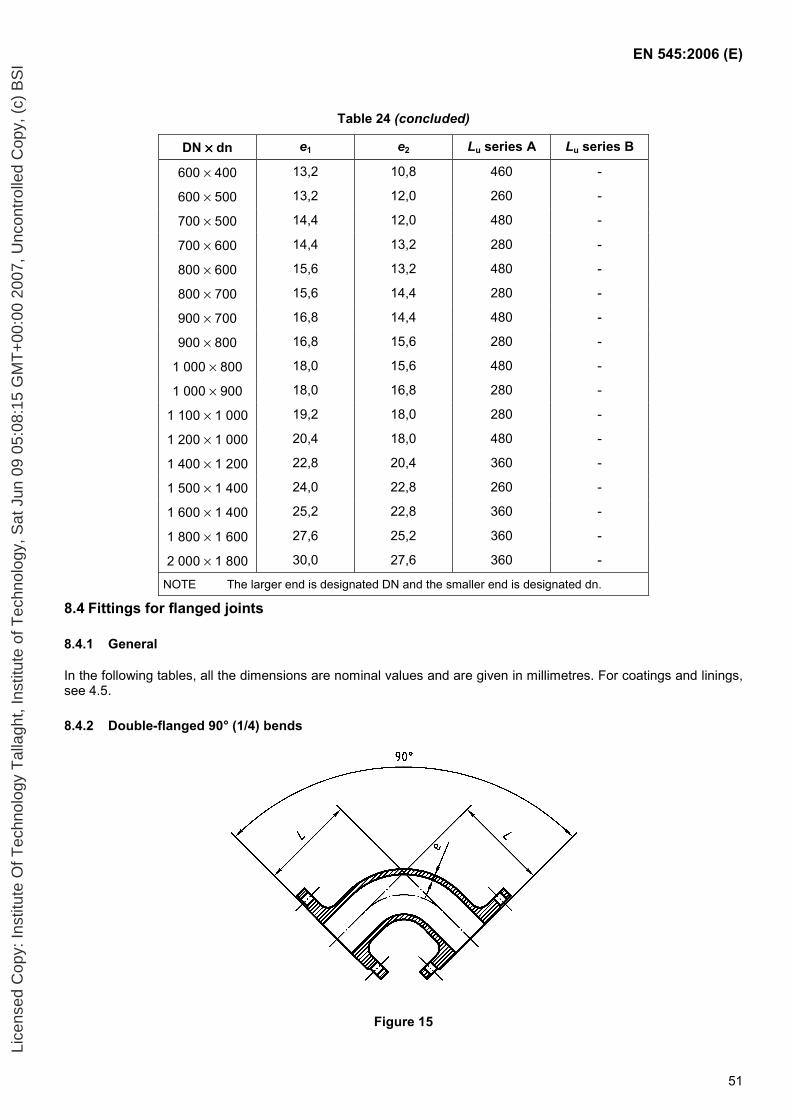
EN 545:2006 (E)
51
Table 24 (concluded)
DN ×××× dn e1 e2 Lu series A Lu series B
600 × 400 13,2 10,8 460 -
600 × 500 13,2 12,0 260 -
700 × 500 14,4 12,0 480 -
700 × 600 14,4 13,2 280 -
800 × 600 15,6 13,2 480 -
800 × 700 15,6 14,4 280 -
900 × 700 16,8 14,4 480 -
900 × 800 16,8 15,6 280 -
1 000 × 800 18,0 15,6 480 -
1 000 × 900 18,0 16,8 280 -
1 100 × 1 000 19,2 18,0 280 -
1 200 × 1 000 20,4 18,0 480 -
1 400 × 1 200 22,8 20,4 360 -
1 500 × 1 400 24,0 22,8 260 -
1 600 × 1 400 25,2 22,8 360 -
1 800 × 1 600 27,6 25,2 360 -
2 000 × 1 800 30,0 27,6 360 -
NOTE The larger end is designated DN and the smaller end is designated dn.
8.4 Fittings for flanged joints
8.4.1 General
In the following tables, all the dimensions are nominal values and are given in millimetres. For coatings and linings, see 4.5.
8.4.2 Double-flanged 90° (1/4) bends
Figure 15
Lice
nsed
Cop
y: In
stitu
te O
f Tec
hnol
ogy
Tal
lagh
t, In
stitu
te o
f Tec
hnol
ogy,
Sat
Jun
09
05:0
8:15
GM
T+
00:0
0 20
07, U
ncon
trol
led
Cop
y, (
c) B
SI
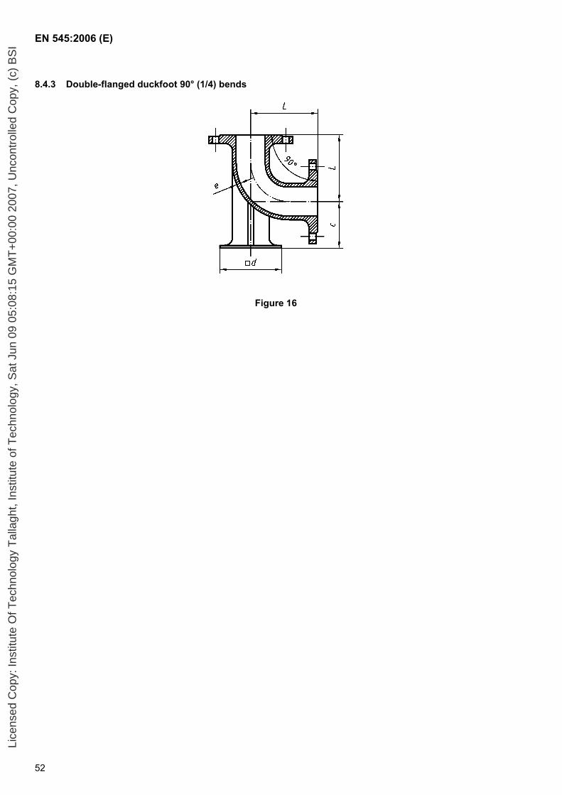
EN 545:2006 (E)
52
8.4.3 Double-flanged duckfoot 90° (1/4) bends
Figure 16
Lice
nsed
Cop
y: In
stitu
te O
f Tec
hnol
ogy
Tal
lagh
t, In
stitu
te o
f Tec
hnol
ogy,
Sat
Jun
09
05:0
8:15
GM
T+
00:0
0 20
07, U
ncon
trol
led
Cop
y, (
c) B
SI
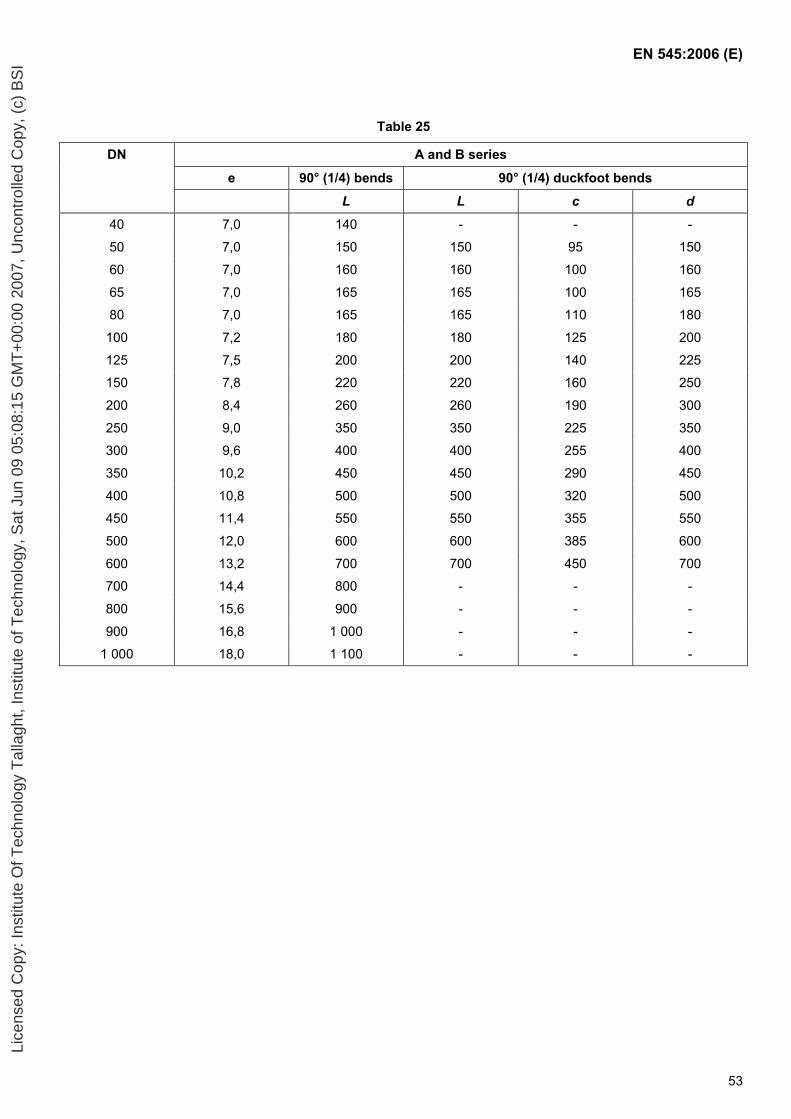
EN 545:2006 (E)
53
Table 25
DN A and B series
e 90° (1/4) bends 90° (1/4) duckfoot bends
L L c d
40 7,0 140 - - -
50 7,0 150 150 95 150
60 7,0 160 160 100 160
65 7,0 165 165 100 165
80 7,0 165 165 110 180
100 7,2 180 180 125 200
125 7,5 200 200 140 225
150 7,8 220 220 160 250
200 8,4 260 260 190 300
250 9,0 350 350 225 350
300 9,6 400 400 255 400
350 10,2 450 450 290 450
400 10,8 500 500 320 500
450 11,4 550 550 355 550
500 12,0 600 600 385 600
600 13,2 700 700 450 700
700 14,4 800 - - -
800 15,6 900 - - -
900 16,8 1 000 - - -
1 000 18,0 1 100 - - -
Lice
nsed
Cop
y: In
stitu
te O
f Tec
hnol
ogy
Tal
lagh
t, In
stitu
te o
f Tec
hnol
ogy,
Sat
Jun
09
05:0
8:15
GM
T+
00:0
0 20
07, U
ncon
trol
led
Cop
y, (
c) B
SI
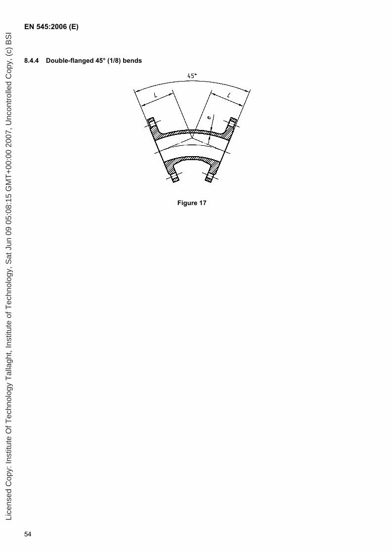
EN 545:2006 (E)
54
8.4.4 Double-flanged 45° (1/8) bends
Figure 17
Lice
nsed
Cop
y: In
stitu
te O
f Tec
hnol
ogy
Tal
lagh
t, In
stitu
te o
f Tec
hnol
ogy,
Sat
Jun
09
05:0
8:15
GM
T+
00:0
0 20
07, U
ncon
trol
led
Cop
y, (
c) B
SI
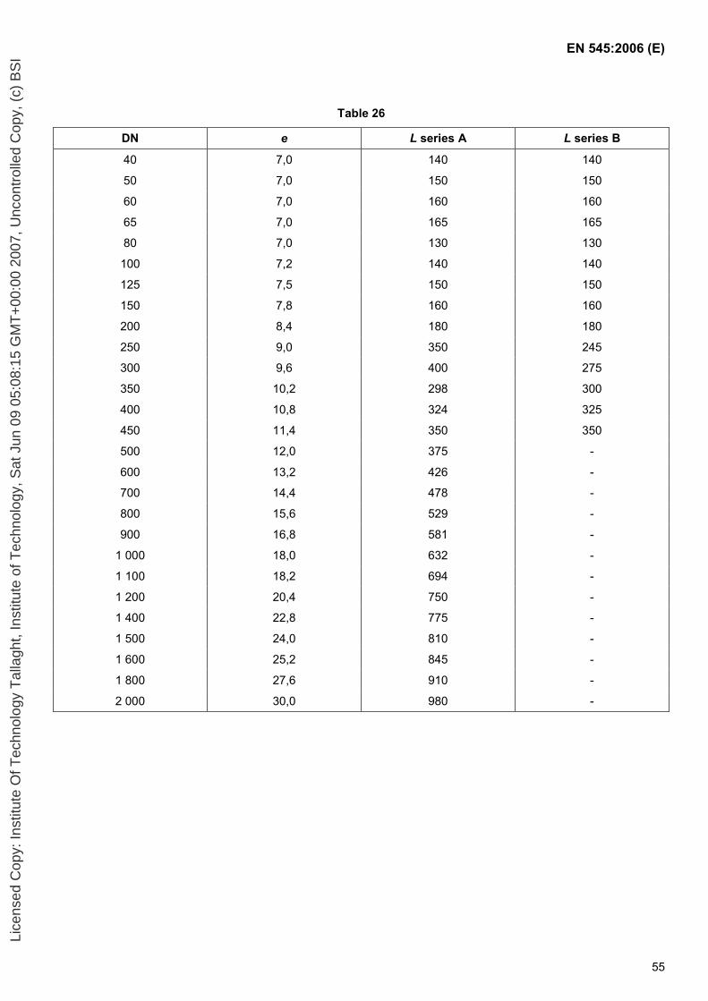
EN 545:2006 (E)
55
Table 26
DN e L series A L series B
40 7,0 140 140
50 7,0 150 150
60 7,0 160 160
65 7,0 165 165
80 7,0 130 130
100 7,2 140 140
125 7,5 150 150
150 7,8 160 160
200 8,4 180 180
250 9,0 350 245
300 9,6 400 275
350 10,2 298 300
400 10,8 324 325
450 11,4 350 350
500 12,0 375 -
600 13,2 426 -
700 14,4 478 -
800 15,6 529 -
900 16,8 581 -
1 000 18,0 632 -
1 100 18,2 694 -
1 200 20,4 750 -
1 400 22,8 775 -
1 500 24,0 810 -
1 600 25,2 845 -
1 800 27,6 910 -
2 000 30,0 980 -
Lice
nsed
Cop
y: In
stitu
te O
f Tec
hnol
ogy
Tal
lagh
t, In
stitu
te o
f Tec
hnol
ogy,
Sat
Jun
09
05:0
8:15
GM
T+
00:0
0 20
07, U
ncon
trol
led
Cop
y, (
c) B
SI
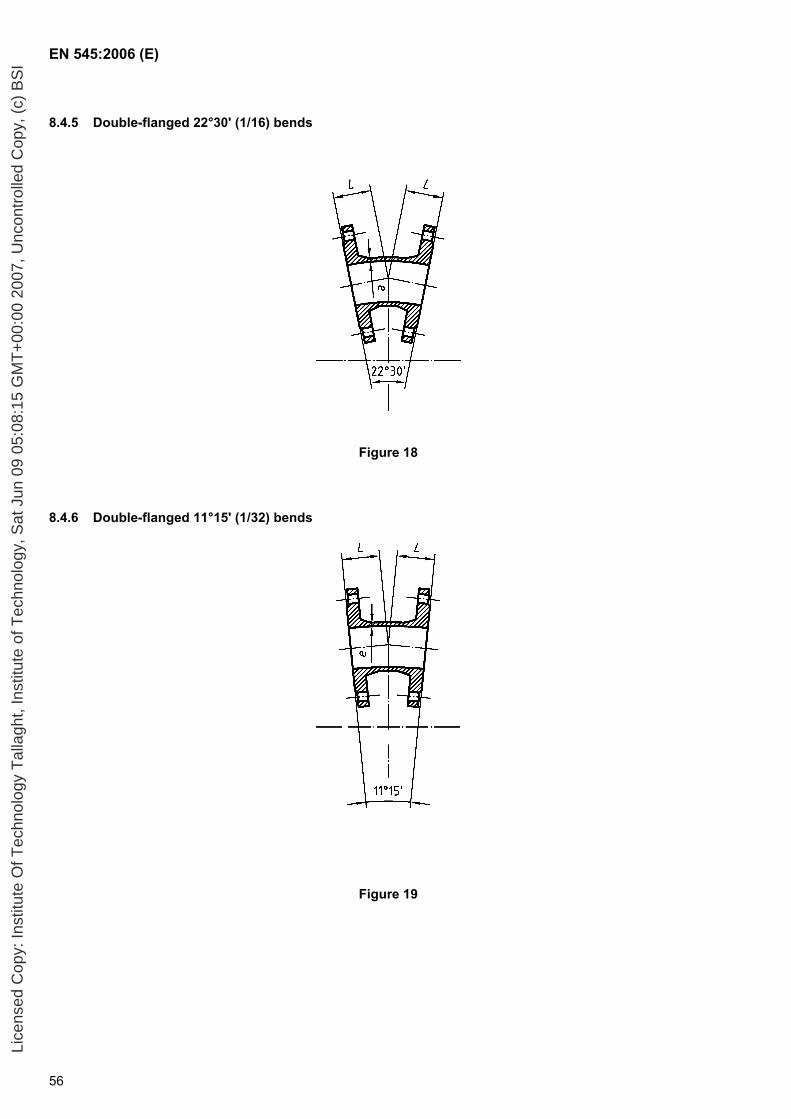
EN 545:2006 (E)
56
8.4.5 Double-flanged 22°30' (1/16) bends
Figure 18
8.4.6 Double-flanged 11°15' (1/32) bends
Figure 19
Lice
nsed
Cop
y: In
stitu
te O
f Tec
hnol
ogy
Tal
lagh
t, In
stitu
te o
f Tec
hnol
ogy,
Sat
Jun
09
05:0
8:15
GM
T+
00:0
0 20
07, U
ncon
trol
led
Cop
y, (
c) B
SI
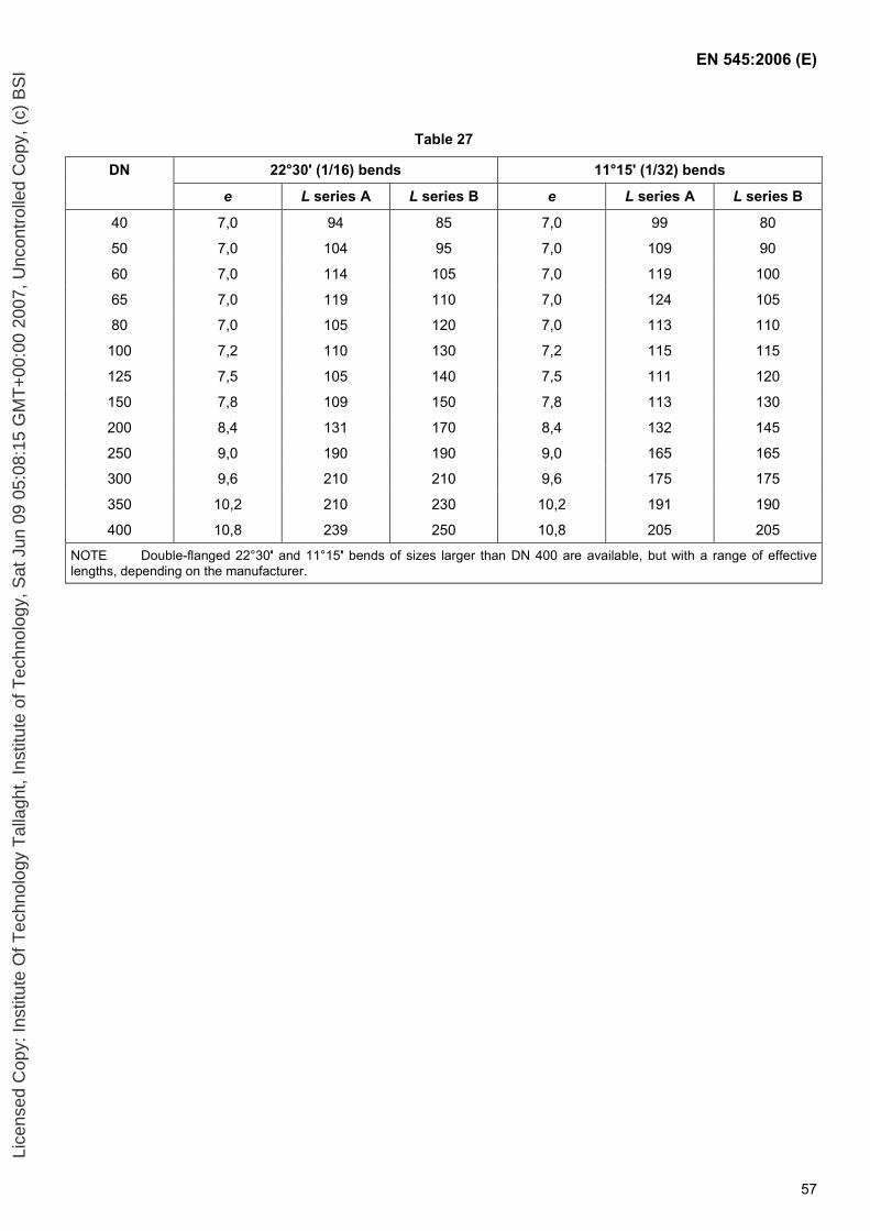
EN 545:2006 (E)
57
Table 27
DN 22°30' (1/16) bends 11°15' (1/32) bends
e L series A L series B e L series A L series B
40 7,0 94 85 7,0 99 80
50 7,0 104 95 7,0 109 90
60 7,0 114 105 7,0 119 100
65 7,0 119 110 7,0 124 105
80 7,0 105 120 7,0 113 110
100 7,2 110 130 7,2 115 115
125 7,5 105 140 7,5 111 120
150 7,8 109 150 7,8 113 130
200 8,4 131 170 8,4 132 145
250 9,0 190 190 9,0 165 165
300 9,6 210 210 9,6 175 175
350 10,2 210 230 10,2 191 190
400 10,8 239 250 10,8 205 205
NOTE Double-flanged 22°30' and 11°15' bends of sizes larger than DN 400 are available, but with a range of effective lengths, depending on the manufacturer.
Lice
nsed
Cop
y: In
stitu
te O
f Tec
hnol
ogy
Tal
lagh
t, In
stitu
te o
f Tec
hnol
ogy,
Sat
Jun
09
05:0
8:15
GM
T+
00:0
0 20
07, U
ncon
trol
led
Cop
y, (
c) B
SI
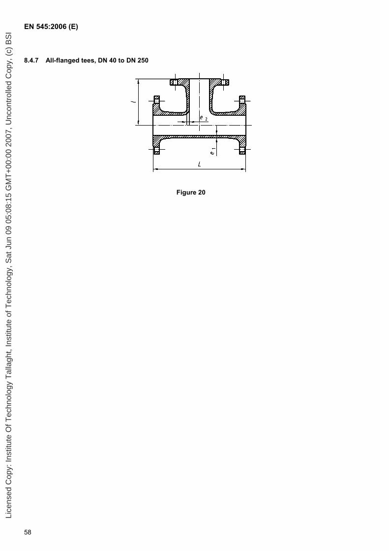
EN 545:2006 (E)
58
8.4.7 All-flanged tees, DN 40 to DN 250
Figure 20
Lice
nsed
Cop
y: In
stitu
te O
f Tec
hnol
ogy
Tal
lagh
t, In
stitu
te o
f Tec
hnol
ogy,
Sat
Jun
09
05:0
8:15
GM
T+
00:0
0 20
07, U
ncon
trol
led
Cop
y, (
c) B
SI
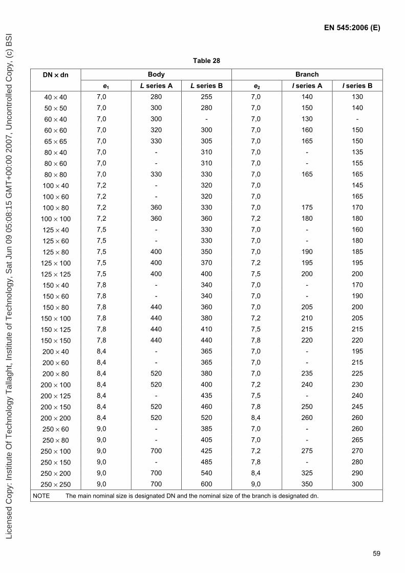
EN 545:2006 (E)
59
Table 28
DN ×××× dn Body Branch e1 L series A L series B e2 l series A l series B
40 × 40 7,0 280 255 7,0 140 130
50 × 50 7,0 300 280 7,0 150 140
60 × 40 7,0 300 - 7,0 130 -
60 × 60 7,0 320 300 7,0 160 150
65 × 65 7,0 330 305 7,0 165 150
80 × 40 7,0 - 310 7,0 - 135
80 × 60 7,0 - 310 7,0 - 155
80 × 80 7,0 330 330 7,0 165 165
100 × 40 7,2 - 320 7,0 145
100 × 60 7,2 - 320 7,0 165
100 × 80 7,2 360 330 7,0 175 170
100 × 100 7,2 360 360 7,2 180 180
125 × 40 7,5 - 330 7,0 - 160
125 × 60 7,5 - 330 7,0 - 180
125 × 80 7,5 400 350 7,0 190 185
125 × 100 7,5 400 370 7,2 195 195
125 × 125 7,5 400 400 7,5 200 200
150 × 40 7,8 - 340 7,0 - 170
150 × 60 7,8 - 340 7,0 - 190
150 × 80 7,8 440 360 7,0 205 200
150 × 100 7,8 440 380 7,2 210 205
150 × 125 7,8 440 410 7,5 215 215
150 × 150 7,8 440 440 7,8 220 220
200 × 40 8,4 - 365 7,0 - 195
200 × 60 8,4 - 365 7,0 - 215
200 × 80 8,4 520 380 7,0 235 225
200 × 100 8,4 520 400 7,2 240 230
200 × 125 8,4 - 435 7,5 - 240
200 × 150 8,4 520 460 7,8 250 245
200 × 200 8,4 520 520 8,4 260 260
250 × 60 9,0 - 385 7,0 - 260
250 × 80 9,0 - 405 7,0 - 265
250 × 100 9,0 700 425 7,2 275 270
250 × 150 9,0 - 485 7,8 - 280
250 × 200 9,0 700 540 8,4 325 290
250 × 250 9,0 700 600 9,0 350 300
NOTE The main nominal size is designated DN and the nominal size of the branch is designated dn.
Lice
nsed
Cop
y: In
stitu
te O
f Tec
hnol
ogy
Tal
lagh
t, In
stitu
te o
f Tec
hnol
ogy,
Sat
Jun
09
05:0
8:15
GM
T+
00:0
0 20
07, U
ncon
trol
led
Cop
y, (
c) B
SI
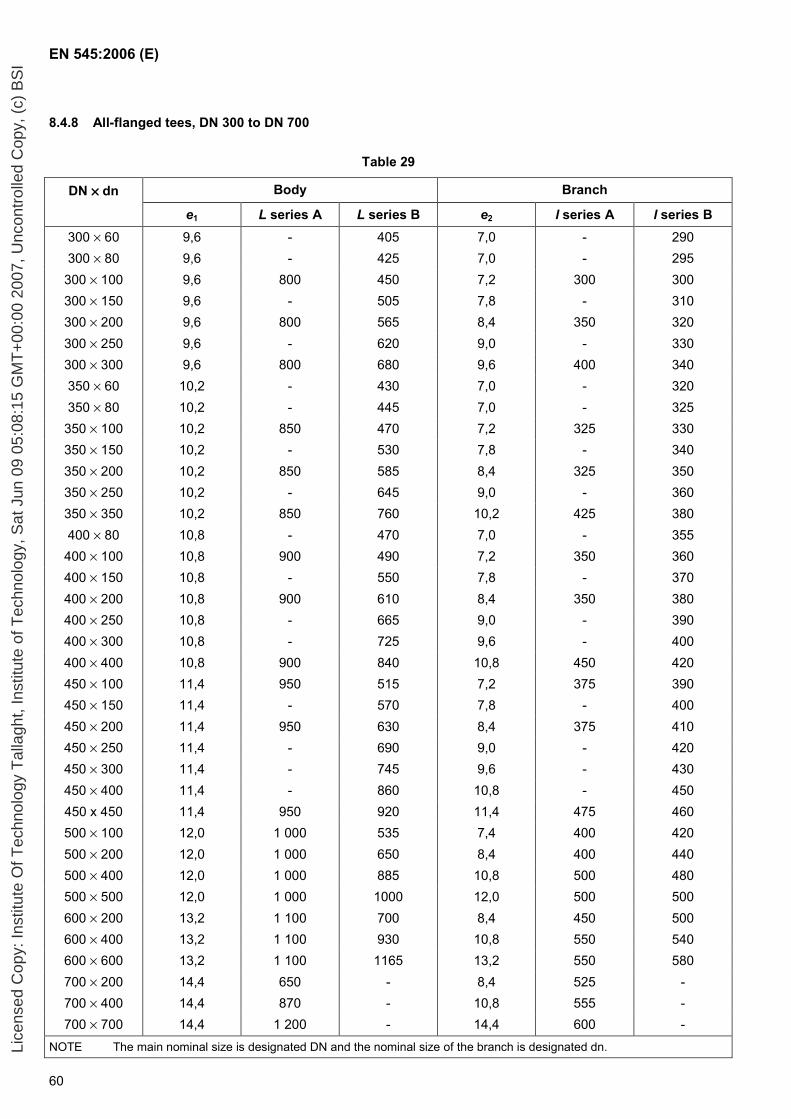
EN 545:2006 (E)
60
8.4.8 All-flanged tees, DN 300 to DN 700
Table 29
DN ×××× dn Body Branch
e1 L series A L series B e2 l series A l series B 300 × 60 9,6 - 405 7,0 - 290 300 × 80 9,6 - 425 7,0 - 295 300 × 100 9,6 800 450 7,2 300 300 300 × 150 9,6 - 505 7,8 - 310 300 × 200 9,6 800 565 8,4 350 320 300 × 250 9,6 - 620 9,0 - 330 300 × 300 9,6 800 680 9,6 400 340 350 × 60 10,2 - 430 7,0 - 320 350 × 80 10,2 - 445 7,0 - 325 350 × 100 10,2 850 470 7,2 325 330 350 × 150 10,2 - 530 7,8 - 340 350 × 200 10,2 850 585 8,4 325 350 350 × 250 10,2 - 645 9,0 - 360 350 × 350 10,2 850 760 10,2 425 380 400 × 80 10,8 - 470 7,0 - 355 400 × 100 10,8 900 490 7,2 350 360 400 × 150 10,8 - 550 7,8 - 370 400 × 200 10,8 900 610 8,4 350 380 400 × 250 10,8 - 665 9,0 - 390 400 × 300 10,8 - 725 9,6 - 400 400 × 400 10,8 900 840 10,8 450 420 450 × 100 11,4 950 515 7,2 375 390 450 × 150 11,4 - 570 7,8 - 400 450 × 200 11,4 950 630 8,4 375 410 450 × 250 11,4 - 690 9,0 - 420 450 × 300 11,4 - 745 9,6 - 430 450 × 400 11,4 - 860 10,8 - 450 450 x 450 11,4 950 920 11,4 475 460 500 × 100 12,0 1 000 535 7,4 400 420 500 × 200 12,0 1 000 650 8,4 400 440 500 × 400 12,0 1 000 885 10,8 500 480 500 × 500 12,0 1 000 1000 12,0 500 500 600 × 200 13,2 1 100 700 8,4 450 500 600 × 400 13,2 1 100 930 10,8 550 540 600 × 600 13,2 1 100 1165 13,2 550 580 700 × 200 14,4 650 - 8,4 525 - 700 × 400 14,4 870 - 10,8 555 - 700 × 700 14,4 1 200 - 14,4 600 -
NOTE The main nominal size is designated DN and the nominal size of the branch is designated dn. Lice
nsed
Cop
y: In
stitu
te O
f Tec
hnol
ogy
Tal
lagh
t, In
stitu
te o
f Tec
hnol
ogy,
Sat
Jun
09
05:0
8:15
GM
T+
00:0
0 20
07, U
ncon
trol
led
Cop
y, (
c) B
SI
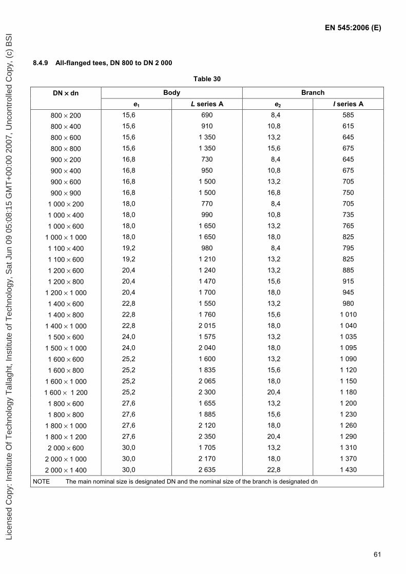
EN 545:2006 (E)
61
8.4.9 All-flanged tees, DN 800 to DN 2 000
Table 30
DN ×××× dn Body Branch e1 L series A e2 l series A
800 × 200 15,6 690 8,4 585
800 × 400 15,6 910 10,8 615
800 × 600 15,6 1 350 13,2 645
800 × 800 15,6 1 350 15,6 675
900 × 200 16,8 730 8,4 645
900 × 400 16,8 950 10,8 675
900 × 600 16,8 1 500 13,2 705
900 × 900 16,8 1 500 16,8 750
1 000 × 200 18,0 770 8,4 705
1 000 × 400 18,0 990 10,8 735
1 000 × 600 18,0 1 650 13,2 765
1 000 × 1 000 18,0 1 650 18,0 825
1 100 × 400 19,2 980 8,4 795
1 100 × 600 19,2 1 210 13,2 825
1 200 × 600 20,4 1 240 13,2 885
1 200 × 800 20,4 1 470 15,6 915
1 200 × 1 000 20,4 1 700 18,0 945
1 400 × 600 22,8 1 550 13,2 980
1 400 × 800 22,8 1 760 15,6 1 010
1 400 × 1 000 22,8 2 015 18,0 1 040
1 500 × 600 24,0 1 575 13,2 1 035
1 500 × 1 000 24,0 2 040 18,0 1 095
1 600 × 600 25,2 1 600 13,2 1 090
1 600 × 800 25,2 1 835 15,6 1 120
1 600 × 1 000 25,2 2 065 18,0 1 150
1 600 × 1 200 25,2 2 300 20,4 1 180
1 800 × 600 27,6 1 655 13,2 1 200
1 800 × 800 27,6 1 885 15,6 1 230
1 800 × 1 000 27,6 2 120 18,0 1 260
1 800 × 1 200 27,6 2 350 20,4 1 290
2 000 × 600 30,0 1 705 13,2 1 310
2 000 × 1 000 30,0 2 170 18,0 1 370
2 000 × 1 400 30,0 2 635 22,8 1 430
NOTE The main nominal size is designated DN and the nominal size of the branch is designated dn
Lice
nsed
Cop
y: In
stitu
te O
f Tec
hnol
ogy
Tal
lagh
t, In
stitu
te o
f Tec
hnol
ogy,
Sat
Jun
09
05:0
8:15
GM
T+
00:0
0 20
07, U
ncon
trol
led
Cop
y, (
c) B
SI
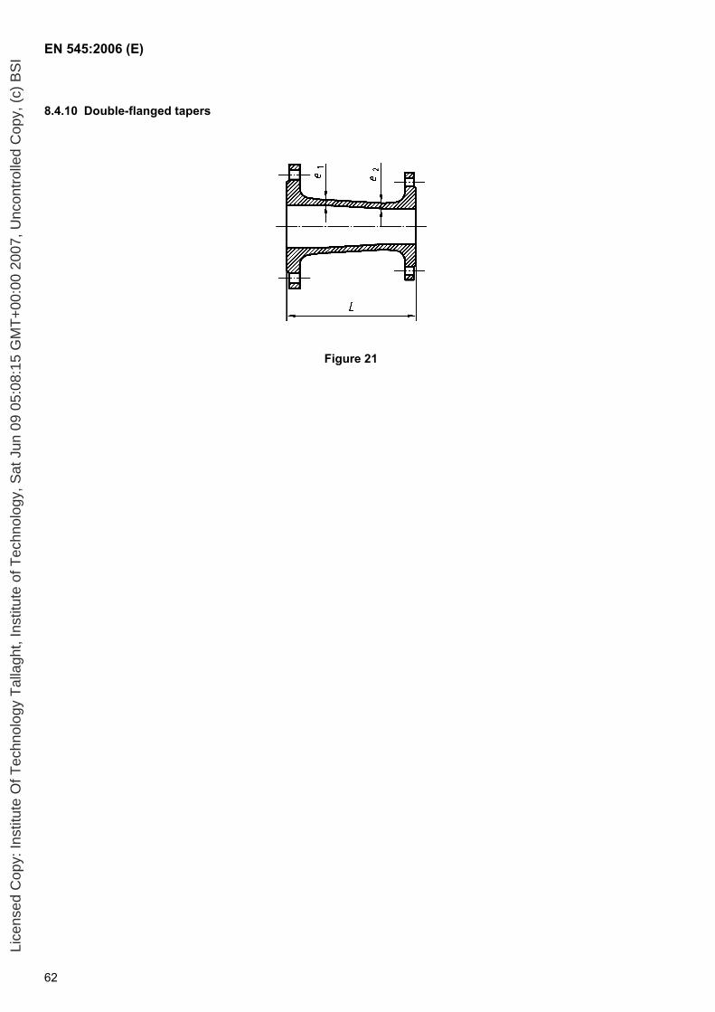
EN 545:2006 (E)
62
8.4.10 Double-flanged tapers
Figure 21
Lice
nsed
Cop
y: In
stitu
te O
f Tec
hnol
ogy
Tal
lagh
t, In
stitu
te o
f Tec
hnol
ogy,
Sat
Jun
09
05:0
8:15
GM
T+
00:0
0 20
07, U
ncon
trol
led
Cop
y, (
c) B
SI
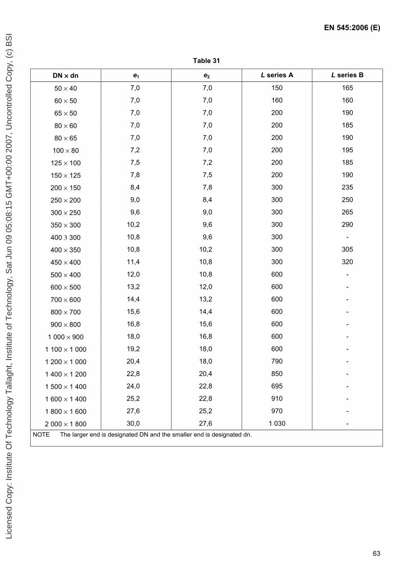
EN 545:2006 (E)
63
Table 31
DN ×××× dn e1 e2 L series A L series B
50 × 40 7,0 7,0 150 165
60 × 50 7,0 7,0 160 160
65 × 50 7,0 7,0 200 190
80 × 60 7,0 7,0 200 185
80 × 65 7,0 7,0 200 190
100 × 80 7,2 7,0 200 195
125 × 100 7,5 7,2 200 185
150 × 125 7,8 7,5 200 190
200 × 150 8,4 7,8 300 235
250 × 200 9,0 8,4 300 250
300 × 250 9,6 9,0 300 265
350 × 300 10,2 9,6 300 290
400 3 300 10,8 9,6 300 -
400 × 350 10,8 10,2 300 305
450 × 400 11,4 10,8 300 320
500 × 400 12,0 10,8 600 -
600 × 500 13,2 12,0 600 -
700 × 600 14,4 13,2 600 -
800 × 700 15,6 14,4 600 -
900 × 800 16,8 15,6 600 -
1 000 × 900 18,0 16,8 600 -
1 100 × 1 000 19,2 18,0 600 -
1 200 × 1 000 20,4 18,0 790 -
1 400 × 1 200 22,8 20,4 850 -
1 500 × 1 400 24,0 22,8 695 -
1 600 × 1 400 25,2 22,8 910 -
1 800 × 1 600 27,6 25,2 970 -
2 000 × 1 800 30,0 27,6 1 030 - NOTE The larger end is designated DN and the smaller end is designated dn.
Lice
nsed
Cop
y: In
stitu
te O
f Tec
hnol
ogy
Tal
lagh
t, In
stitu
te o
f Tec
hnol
ogy,
Sat
Jun
09
05:0
8:15
GM
T+
00:0
0 20
07, U
ncon
trol
led
Cop
y, (
c) B
SI

EN 545:2006 (E)
64
8.4.11 Blank flanges PN 10
Figure 22
8.4.12 Blank flanges PN 16
Figure 23
Lice
nsed
Cop
y: In
stitu
te O
f Tec
hnol
ogy
Tal
lagh
t, In
stitu
te o
f Tec
hnol
ogy,
Sat
Jun
09
05:0
8:15
GM
T+
00:0
0 20
07, U
ncon
trol
led
Cop
y, (
c) B
SI
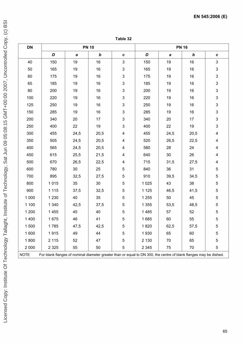
EN 545:2006 (E)
65
Table 32
DN PN 10 PN 16
D a b c D a b c
40 150 19 16 3 150 19 16 3
50 165 19 16 3 165 19 16 3
60 175 19 16 3 175 19 16 3
65 185 19 16 3 185 19 16 3
80 200 19 16 3 200 19 16 3
100 220 19 16 3 220 19 16 3
125 250 19 16 3 250 19 16 3
150 285 19 16 3 285 19 16 3
200 340 20 17 3 340 20 17 3
250 400 22 19 3 400 22 19 3
300 455 24,5 20,5 4 455 24,5 20,5 4
350 505 24,5 20,5 4 520 26,5 22,5 4
400 565 24,5 20,5 4 580 28 24 4
450 615 25,5 21,5 4 640 30 26 4
500 670 26,5 22,5 4 715 31,5 27,5 4
600 780 30 25 5 840 36 31 5
700 895 32,5 27,5 5 910 39,5 34,5 5
800 1 015 35 30 5 1 025 43 38 5
900 1 115 37,5 32,5 5 1 125 46,5 41,5 5
1 000 1 230 40 35 5 1 255 50 45 5
1 100 1 340 42,5 37,5 5 1 355 53,5 48,5 5
1 200 1 455 45 40 5 1 485 57 52 5
1 400 1 675 46 41 5 1 685 60 55 5
1 500 1 785 47,5 42,5 5 1 820 62,5 57,5 5
1 600 1 915 49 44 5 1 930 65 60 5
1 800 2 115 52 47 5 2 130 70 65 5
2 000 2 325 55 50 5 2 345 75 70 5
NOTE For blank flanges of nominal diameter greater than or equal to DN 300, the centre of blank flanges may be dished.
Lice
nsed
Cop
y: In
stitu
te O
f Tec
hnol
ogy
Tal
lagh
t, In
stitu
te o
f Tec
hnol
ogy,
Sat
Jun
09
05:0
8:15
GM
T+
00:0
0 20
07, U
ncon
trol
led
Cop
y, (
c) B
SI
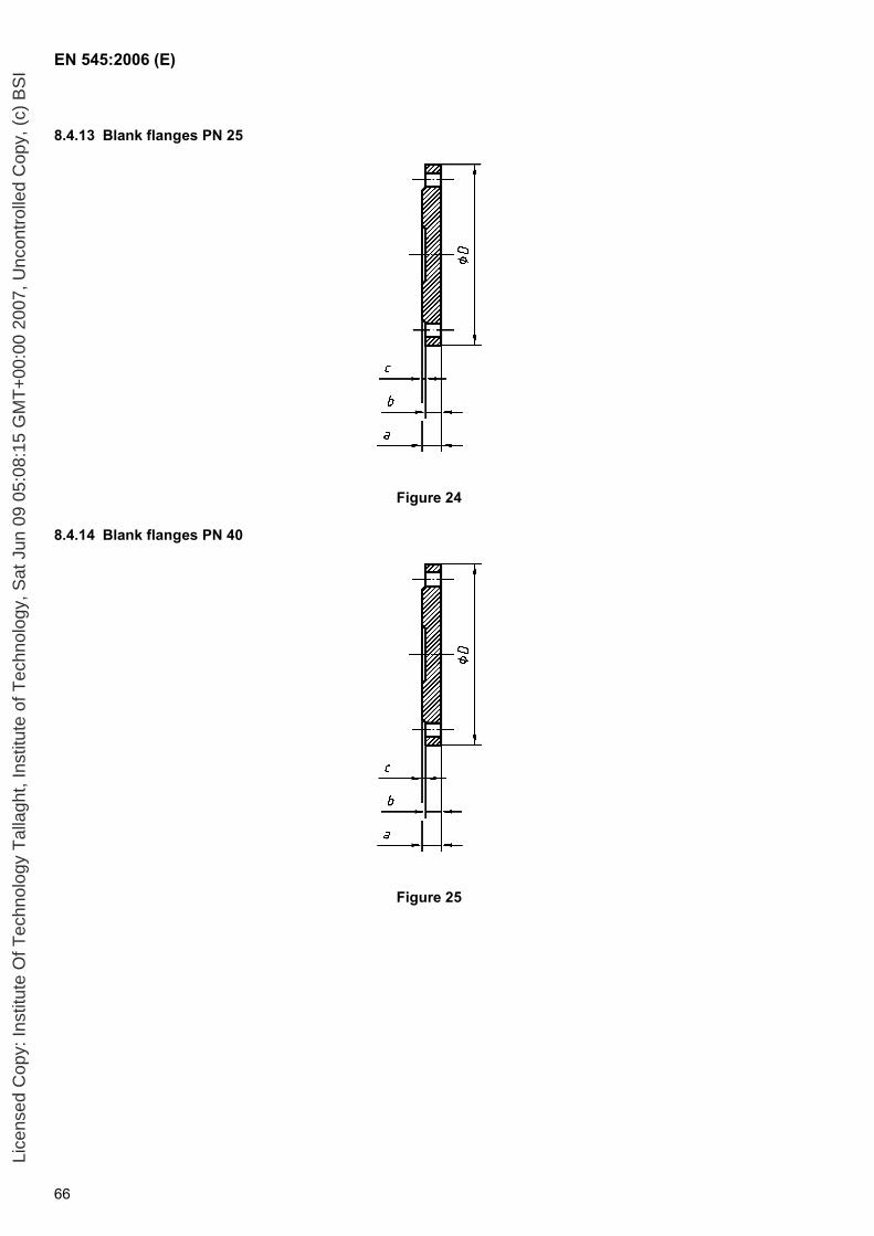
EN 545:2006 (E)
66
8.4.13 Blank flanges PN 25
Figure 24
8.4.14 Blank flanges PN 40
Figure 25
Lice
nsed
Cop
y: In
stitu
te O
f Tec
hnol
ogy
Tal
lagh
t, In
stitu
te o
f Tec
hnol
ogy,
Sat
Jun
09
05:0
8:15
GM
T+
00:0
0 20
07, U
ncon
trol
led
Cop
y, (
c) B
SI
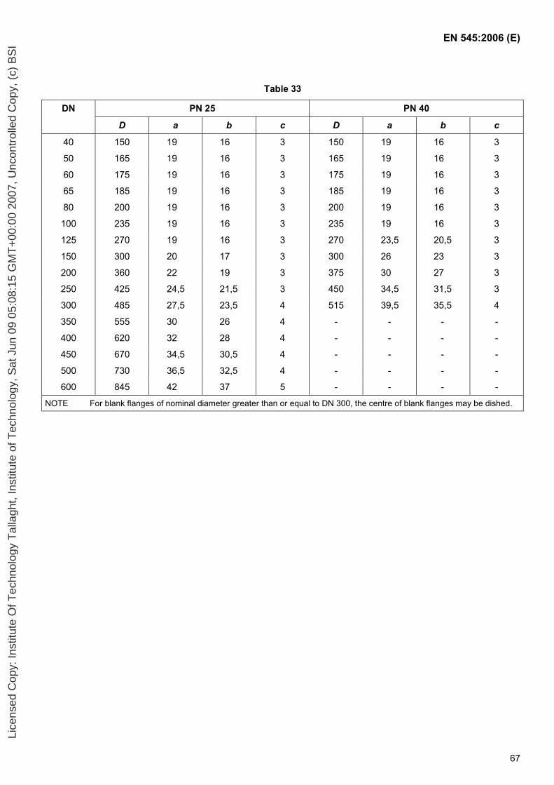
EN 545:2006 (E)
67
Table 33
DN PN 25 PN 40
D a b c D a b c
40 150 19 16 3 150 19 16 3
50 165 19 16 3 165 19 16 3
60 175 19 16 3 175 19 16 3
65 185 19 16 3 185 19 16 3
80 200 19 16 3 200 19 16 3
100 235 19 16 3 235 19 16 3
125 270 19 16 3 270 23,5 20,5 3
150 300 20 17 3 300 26 23 3
200 360 22 19 3 375 30 27 3
250 425 24,5 21,5 3 450 34,5 31,5 3
300 485 27,5 23,5 4 515 39,5 35,5 4
350 555 30 26 4 - - - -
400 620 32 28 4 - - - -
450 670 34,5 30,5 4 - - - -
500 730 36,5 32,5 4 - - - -
600 845 42 37 5 - - - -
NOTE For blank flanges of nominal diameter greater than or equal to DN 300, the centre of blank flanges may be dished.
Lice
nsed
Cop
y: In
stitu
te O
f Tec
hnol
ogy
Tal
lagh
t, In
stitu
te o
f Tec
hnol
ogy,
Sat
Jun
09
05:0
8:15
GM
T+
00:0
0 20
07, U
ncon
trol
led
Cop
y, (
c) B
SI
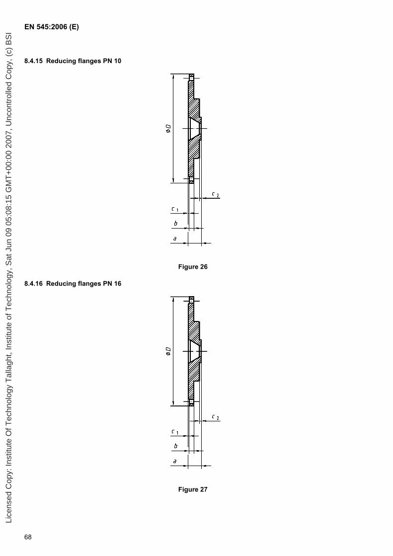
EN 545:2006 (E)
68
8.4.15 Reducing flanges PN 10
Figure 26
8.4.16 Reducing flanges PN 16
Figure 27
Lice
nsed
Cop
y: In
stitu
te O
f Tec
hnol
ogy
Tal
lagh
t, In
stitu
te o
f Tec
hnol
ogy,
Sat
Jun
09
05:0
8:15
GM
T+
00:0
0 20
07, U
ncon
trol
led
Cop
y, (
c) B
SI
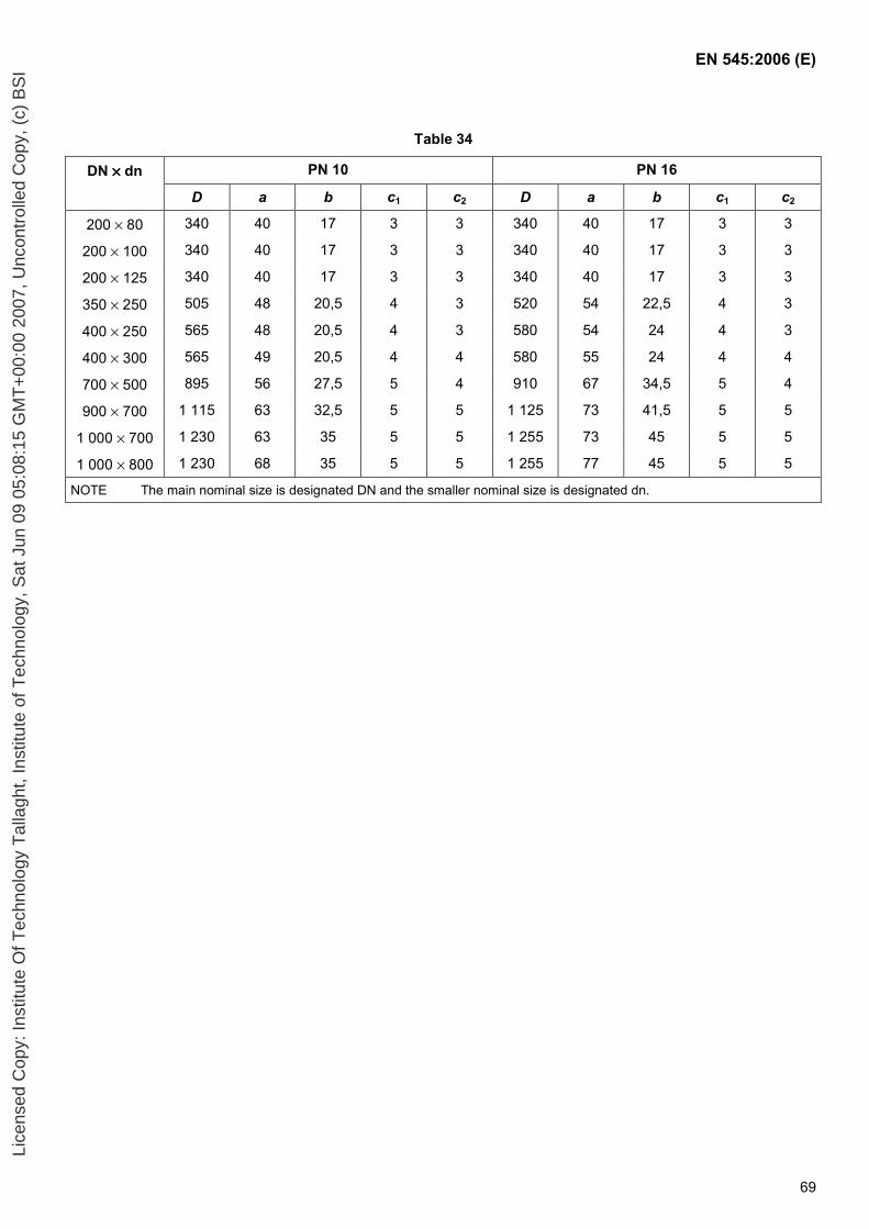
EN 545:2006 (E)
69
Table 34
DN ×××× dn PN 10 PN 16
D a b c1 c2 D a b c1 c2
200 × 80 340 40 17 3 3 340 40 17 3 3
200 × 100 340 40 17 3 3 340 40 17 3 3
200 × 125 340 40 17 3 3 340 40 17 3 3
350 × 250 505 48 20,5 4 3 520 54 22,5 4 3
400 × 250 565 48 20,5 4 3 580 54 24 4 3
400 × 300 565 49 20,5 4 4 580 55 24 4 4
700 × 500 895 56 27,5 5 4 910 67 34,5 5 4
900 × 700 1 115 63 32,5 5 5 1 125 73 41,5 5 5
1 000 × 700 1 230 63 35 5 5 1 255 73 45 5 5
1 000 × 800 1 230 68 35 5 5 1 255 77 45 5 5
NOTE The main nominal size is designated DN and the smaller nominal size is designated dn.
Lice
nsed
Cop
y: In
stitu
te O
f Tec
hnol
ogy
Tal
lagh
t, In
stitu
te o
f Tec
hnol
ogy,
Sat
Jun
09
05:0
8:15
GM
T+
00:0
0 20
07, U
ncon
trol
led
Cop
y, (
c) B
SI

EN 545:2006 (E)
70
8.4.17 Reducing flanges PN 25
Figure 28
8.4.18 Reducing flanges PN 40
Figure 29
Lice
nsed
Cop
y: In
stitu
te O
f Tec
hnol
ogy
Tal
lagh
t, In
stitu
te o
f Tec
hnol
ogy,
Sat
Jun
09
05:0
8:15
GM
T+
00:0
0 20
07, U
ncon
trol
led
Cop
y, (
c) B
SI
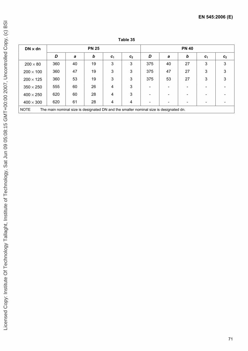
EN 545:2006 (E)
71
Table 35
DN ×××× dn PN 25 PN 40
D a b c1 c2 D a b c1 c2
200 × 80 360 40 19 3 3 375 40 27 3 3
200 × 100 360 47 19 3 3 375 47 27 3 3
200 × 125 360 53 19 3 3 375 53 27 3 3
350 × 250 555 60 26 4 3 - - - - -
400 × 250 620 60 28 4 3 - - - - -
400 × 300 620 61 28 4 4 - - - - -
NOTE The main nominal size is designated DN and the smaller nominal size is designated dn.
Lice
nsed
Cop
y: In
stitu
te O
f Tec
hnol
ogy
Tal
lagh
t, In
stitu
te o
f Tec
hnol
ogy,
Sat
Jun
09
05:0
8:15
GM
T+
00:0
0 20
07, U
ncon
trol
led
Cop
y, (
c) B
SI
EN 545:2006 (E)
72
Annex A (normative)
Allowable pressures
A.1 General
The maximum values of PFA, PMA and PEA for pipes and fittings, as defined in 3.19, 3.20 and 3.21 respectively, shall be as given (in bars) in A.2, A.3 and A.4.
Appropriate limitations shall be taken into account which may prevent the full range of these pressures being used in an installed pipeline, for example:
operation at the PFA and PMA values given in A.2 for socket and spigot pipes may be limited by the lower pressure capability of other pipeline components, e.g. flanged pipework (see A.4), certain types of tees (see A.3) and specific designs of flexible joints (see 5.2.2);
site hydrostatic testing at the high PEA values given in A.2 may be limited by the type and design of the pipeline anchorage system and/or the design of flexible joints.
A.2 Socket and spigot pipes (see 8.1)
The maximum values of PFA, PMA and PEA as given in Table A.1 are calculated as follows:
a) with a maximum of 64 bar for Class 40 pipes, and of 85 bar for Class K 9 and K 10 pipes,
F
m
SDRe
PFA⋅
⋅⋅= min20
where:
emin is the minimum pipe wall thickness, in millimetres;
D is the mean pipe diameter (DE - emin), in millimetres;
DE is the nominal pipe external diameter (see Table 15), in millimetres;
Rm is the minimum tensile strength of ductile iron, in megapascals (Rm = 420 MPa ; see 4.3.1);
SF is a safety factor of 3.
b) PMA : as PFA, but with SF = 2,5 ; therefore
PMA = 1,2 x PFA .
c) PEA = PMA + 5 bar.
Lice
nsed
Cop
y: In
stitu
te O
f Tec
hnol
ogy
Tal
lagh
t, In
stitu
te o
f Tec
hnol
ogy,
Sat
Jun
09
05:0
8:15
GM
T+
00:0
0 20
07, U
ncon
trol
led
Cop
y, (
c) B
SI

EN 545:2006 (E)
73
A.3 Fittings for socketed joints (see 8.3)
The maximum values of PFA, PMA and PEA are as follows:
socketed fittings, except tees: their PFA, PMA and PEA are equal to those given in A.2 for K9 pipes;
socketed tees: their PFA, PMA and PEA may be less than those given in A.2 for K9 pipes, they shall be given in the manufacturer’s catalogues;
fittings with one flange, such as double-socket tees with flanged branch, flanged spigots and flanged sockets: their PFA, PMA and PEA are limited by their flange; they are equal to those given in A.4 for the corresponding PN and DN.
When other limitations exist due to the joint type or to any specific design arrangement, they shall be given in the manufacturer’s catalogues.
A.4 Flanged pipes (see 8.2) and fittings for flanged joints (see 8.4)
The maximum values for PFA, PMA and PEA are given in Table A.2.
Lice
nsed
Cop
y: In
stitu
te O
f Tec
hnol
ogy
Tal
lagh
t, In
stitu
te o
f Tec
hnol
ogy,
Sat
Jun
09
05:0
8:15
GM
T+
00:0
0 20
07, U
ncon
trol
led
Cop
y, (
c) B
SI
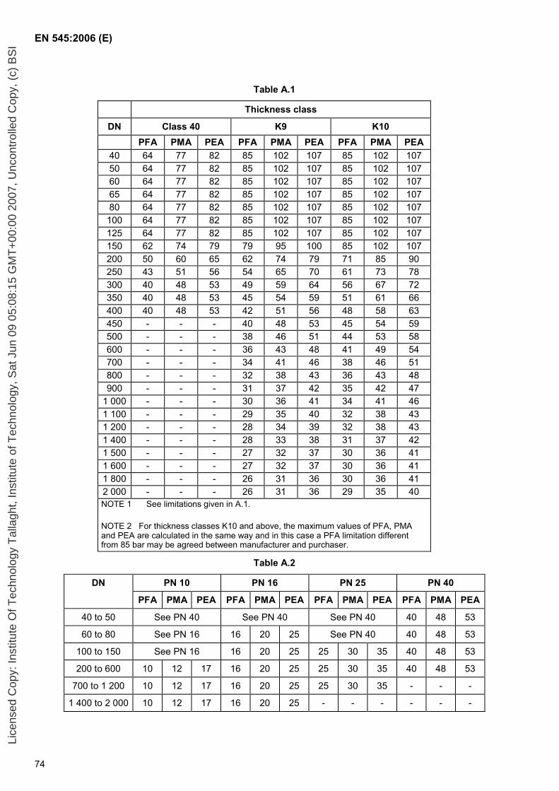
EN 545:2006 (E)
74
Table A.1
Thickness class
DN Class 40 K9 K10 PFA PMA PEA PFA PMA PEA PFA PMA PEA
40 64 77 82 85 102 107 85 102 107 50 64 77 82 85 102 107 85 102 107 60 64 77 82 85 102 107 85 102 107 65 64 77 82 85 102 107 85 102 107 80 64 77 82 85 102 107 85 102 107 100 64 77 82 85 102 107 85 102 107 125 64 77 82 85 102 107 85 102 107 150 62 74 79 79 95 100 85 102 107 200 50 60 65 62 74 79 71 85 90 250 43 51 56 54 65 70 61 73 78 300 40 48 53 49 59 64 56 67 72 350 40 48 53 45 54 59 51 61 66 400 40 48 53 42 51 56 48 58 63 450 - - - 40 48 53 45 54 59 500 - - - 38 46 51 44 53 58 600 - - - 36 43 48 41 49 54 700 - - - 34 41 46 38 46 51 800 - - - 32 38 43 36 43 48 900 - - - 31 37 42 35 42 47
1 000 - - - 30 36 41 34 41 46 1 100 - - - 29 35 40 32 38 43 1 200 - - - 28 34 39 32 38 43 1 400 - - - 28 33 38 31 37 42 1 500 - - - 27 32 37 30 36 41 1 600 - - - 27 32 37 30 36 41 1 800 - - - 26 31 36 30 36 41 2 000 - - - 26 31 36 29 35 40 NOTE 1 See limitations given in A.1.
NOTE 2 For thickness classes K10 and above, the maximum values of PFA, PMA and PEA are calculated in the same way and in this case a PFA limitation different from 85 bar may be agreed between manufacturer and purchaser.
Table A.2
DN PN 10 PN 16 PN 25 PN 40
PFA PMA PEA PFA PMA PEA PFA PMA PEA PFA PMA PEA
40 to 50 See PN 40 See PN 40 See PN 40 40 48 53
60 to 80 See PN 16 16 20 25 See PN 40 40 48 53
100 to 150 See PN 16 16 20 25 25 30 35 40 48 53
200 to 600 10 12 17 16 20 25 25 30 35 40 48 53
700 to 1 200 10 12 17 16 20 25 25 30 35 - - -
1 400 to 2 000 10 12 17 16 20 25 - - - - - -
Lice
nsed
Cop
y: In
stitu
te O
f Tec
hnol
ogy
Tal
lagh
t, In
stitu
te o
f Tec
hnol
ogy,
Sat
Jun
09
05:0
8:15
GM
T+
00:0
0 20
07, U
ncon
trol
led
Cop
y, (
c) B
SI
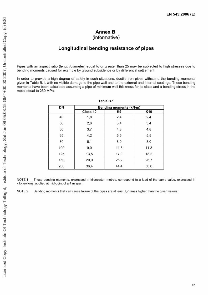
EN 545:2006 (E)
75
Annex B (informative)
Longitudinal bending resistance of pipes
Pipes with an aspect ratio (length/diameter) equal to or greater than 25 may be subjected to high stresses due to bending moments caused for example by ground subsidence or by differential settlement.
In order to provide a high degree of safety in such situations, ductile iron pipes withstand the bending moments given in Table B.1, with no visible damage to the pipe wall and to the external and internal coatings. These bending moments have been calculated assuming a pipe of minimum wall thickness for its class and a bending stress in the metal equal to 250 MPa.
Table B.1
DN Bending moments (kN·m) Class 40 K9 K10
40 1,8 2,4 2,4
50 2,6 3,4 3,4
60 3,7 4,8 4,8
65 4,2 5,5 5,5
80 6,1 8,0 8,0
100 9,0 11,8 11,8
125 13,5 17,9 18,2
150 20,0 25,2 26,7
200 36,4 44,4 50,6
NOTE 1 These bending moments, expressed in kilonewton metres, correspond to a load of the same value, expressed in kilonewtons, applied at mid-point of a 4 m span.
NOTE 2 Bending moments that can cause failure of the pipes are at least 1,7 times higher than the given values.
Lice
nsed
Cop
y: In
stitu
te O
f Tec
hnol
ogy
Tal
lagh
t, In
stitu
te o
f Tec
hnol
ogy,
Sat
Jun
09
05:0
8:15
GM
T+
00:0
0 20
07, U
ncon
trol
led
Cop
y, (
c) B
SI
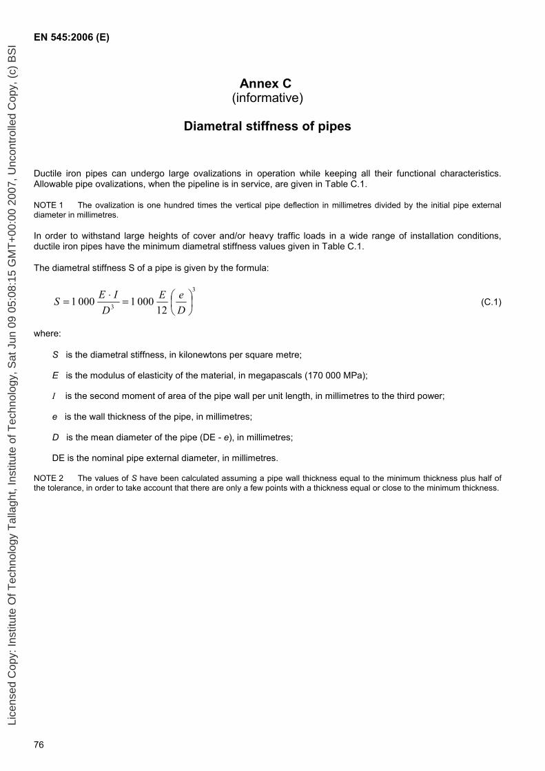
EN 545:2006 (E)
76
Annex C (informative)
Diametral stiffness of pipes
Ductile iron pipes can undergo large ovalizations in operation while keeping all their functional characteristics. Allowable pipe ovalizations, when the pipeline is in service, are given in Table C.1.
NOTE 1 The ovalization is one hundred times the vertical pipe deflection in millimetres divided by the initial pipe external diameter in millimetres.
In order to withstand large heights of cover and/or heavy traffic loads in a wide range of installation conditions, ductile iron pipes have the minimum diametral stiffness values given in Table C.1.
The diametral stiffness S of a pipe is given by the formula:
3
3 1200010001
=⋅=
DeE
DIES (C.1)
where:
S is the diametral stiffness, in kilonewtons per square metre;
E is the modulus of elasticity of the material, in megapascals (170 000 MPa);
I is the second moment of area of the pipe wall per unit length, in millimetres to the third power;
e is the wall thickness of the pipe, in millimetres;
D is the mean diameter of the pipe (DE - e), in millimetres;
DE is the nominal pipe external diameter, in millimetres.
NOTE 2 The values of S have been calculated assuming a pipe wall thickness equal to the minimum thickness plus half of the tolerance, in order to take account that there are only a few points with a thickness equal or close to the minimum thickness.
Lice
nsed
Cop
y: In
stitu
te O
f Tec
hnol
ogy
Tal
lagh
t, In
stitu
te o
f Tec
hnol
ogy,
Sat
Jun
09
05:0
8:15
GM
T+
00:0
0 20
07, U
ncon
trol
led
Cop
y, (
c) B
SI
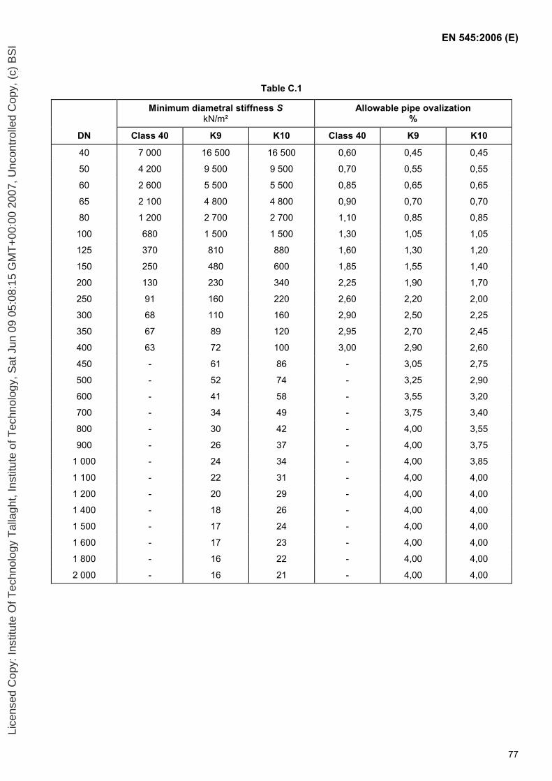
EN 545:2006 (E)
77
Table C.1
Minimum diametral stiffness S kN/m²
Allowable pipe ovalization %
DN Class 40 K9 K10 Class 40 K9 K10
40 7 000 16 500 16 500 0,60 0,45 0,45
50 4 200 9 500 9 500 0,70 0,55 0,55
60 2 600 5 500 5 500 0,85 0,65 0,65
65 2 100 4 800 4 800 0,90 0,70 0,70
80 1 200 2 700 2 700 1,10 0,85 0,85
100 680 1 500 1 500 1,30 1,05 1,05
125 370 810 880 1,60 1,30 1,20
150 250 480 600 1,85 1,55 1,40
200 130 230 340 2,25 1,90 1,70
250 91 160 220 2,60 2,20 2,00
300 68 110 160 2,90 2,50 2,25
350 67 89 120 2,95 2,70 2,45
400 63 72 100 3,00 2,90 2,60
450 - 61 86 - 3,05 2,75
500 - 52 74 - 3,25 2,90
600 - 41 58 - 3,55 3,20
700 - 34 49 - 3,75 3,40
800 - 30 42 - 4,00 3,55
900 - 26 37 - 4,00 3,75
1 000 - 24 34 - 4,00 3,85
1 100 - 22 31 - 4,00 4,00
1 200 - 20 29 - 4,00 4,00
1 400 - 18 26 - 4,00 4,00
1 500 - 17 24 - 4,00 4,00
1 600 - 17 23 - 4,00 4,00
1 800 - 16 22 - 4,00 4,00
2 000 - 16 21 - 4,00 4,00
Lice
nsed
Cop
y: In
stitu
te O
f Tec
hnol
ogy
Tal
lagh
t, In
stitu
te o
f Tec
hnol
ogy,
Sat
Jun
09
05:0
8:15
GM
T+
00:0
0 20
07, U
ncon
trol
led
Cop
y, (
c) B
SI

EN 545:2006 (E)
78
Annex D (informative)
Alternative pipe coatings, field of use, characteristics of soils
D.1 Alternative pipe coatings
The following coatings may also be supplied, depending on the external and internal conditions of use :
a) External coatings:
zinc rich paint coating having a minimum mass of 150 g/m², with finishing layer;
thicker zinc coating having a minimum mass of 200 g/m², with finishing layer;
polyethylene sleeve (as a supplement to the zinc coating with finishing layer);
alloy of zinc and aluminium with or without other metals, having a minimum mass of 400 g/m², with finishing layer;
extruded polyethylene coating in accordance with EN 14628;
polyurethane coating in accordance with EN 15189;
fibre reinforced cement mortar coating according to prEN 15542;
adhesive tape.
b) Internal coatings (linings):
bituminous paint lining;
thicker cement mortar lining;
cement mortar lining with seal coat;
polyurethane lining.
c) Coating of the joint area:
epoxy coating;
polyurethane coating.
For the coatings for the joint area when agreed between the manufacturer and the purchaser, the upper limit deviation on the external diameter DE of the coated spigot may be greater than that specified in 8.1, provided that the interconnection of the products is ensured.
Lice
nsed
Cop
y: In
stitu
te O
f Tec
hnol
ogy
Tal
lagh
t, In
stitu
te o
f Tec
hnol
ogy,
Sat
Jun
09
05:0
8:15
GM
T+
00:0
0 20
07, U
ncon
trol
led
Cop
y, (
c) B
SI
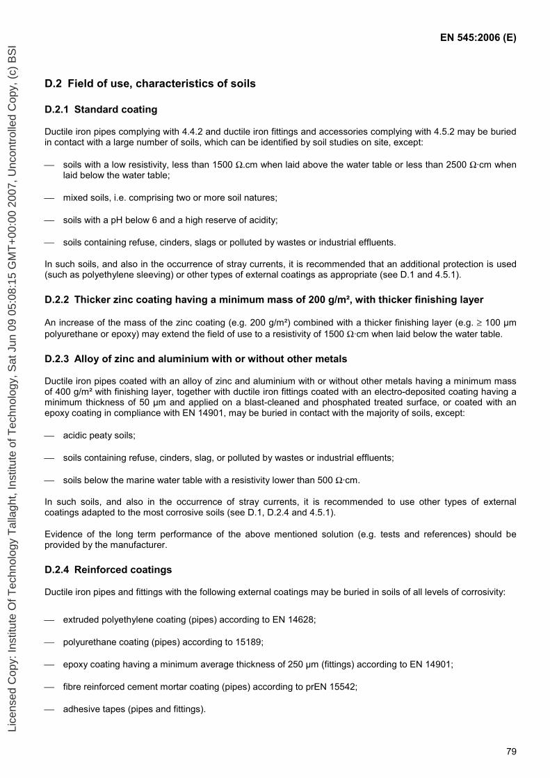
EN 545:2006 (E)
79
D.2 Field of use, characteristics of soils
D.2.1 Standard coating
Ductile iron pipes complying with 4.4.2 and ductile iron fittings and accessories complying with 4.5.2 may be buried in contact with a large number of soils, which can be identified by soil studies on site, except:
soils with a low resistivity, less than 1500 Ω.cm when laid above the water table or less than 2500 Ω·cm when laid below the water table;
mixed soils, i.e. comprising two or more soil natures;
soils with a pH below 6 and a high reserve of acidity;
soils containing refuse, cinders, slags or polluted by wastes or industrial effluents.
In such soils, and also in the occurrence of stray currents, it is recommended that an additional protection is used (such as polyethylene sleeving) or other types of external coatings as appropriate (see D.1 and 4.5.1).
D.2.2 Thicker zinc coating having a minimum mass of 200 g/m², with thicker finishing layer
An increase of the mass of the zinc coating (e.g. 200 g/m²) combined with a thicker finishing layer (e.g. ≥ 100 µm polyurethane or epoxy) may extend the field of use to a resistivity of 1500 Ω·cm when laid below the water table.
D.2.3 Alloy of zinc and aluminium with or without other metals
Ductile iron pipes coated with an alloy of zinc and aluminium with or without other metals having a minimum mass of 400 g/m² with finishing layer, together with ductile iron fittings coated with an electro-deposited coating having a minimum thickness of 50 µm and applied on a blast-cleaned and phosphated treated surface, or coated with an epoxy coating in compliance with EN 14901, may be buried in contact with the majority of soils, except:
acidic peaty soils;
soils containing refuse, cinders, slag, or polluted by wastes or industrial effluents;
soils below the marine water table with a resistivity lower than 500 Ω·cm.
In such soils, and also in the occurrence of stray currents, it is recommended to use other types of external coatings adapted to the most corrosive soils (see D.1, D.2.4 and 4.5.1).
Evidence of the long term performance of the above mentioned solution (e.g. tests and references) should be provided by the manufacturer.
D.2.4 Reinforced coatings
Ductile iron pipes and fittings with the following external coatings may be buried in soils of all levels of corrosivity:
extruded polyethylene coating (pipes) according to EN 14628;
polyurethane coating (pipes) according to 15189;
epoxy coating having a minimum average thickness of 250 µm (fittings) according to EN 14901;
fibre reinforced cement mortar coating (pipes) according to prEN 15542;
adhesive tapes (pipes and fittings).
Lice
nsed
Cop
y: In
stitu
te O
f Tec
hnol
ogy
Tal
lagh
t, In
stitu
te o
f Tec
hnol
ogy,
Sat
Jun
09
05:0
8:15
GM
T+
00:0
0 20
07, U
ncon
trol
led
Cop
y, (
c) B
SI
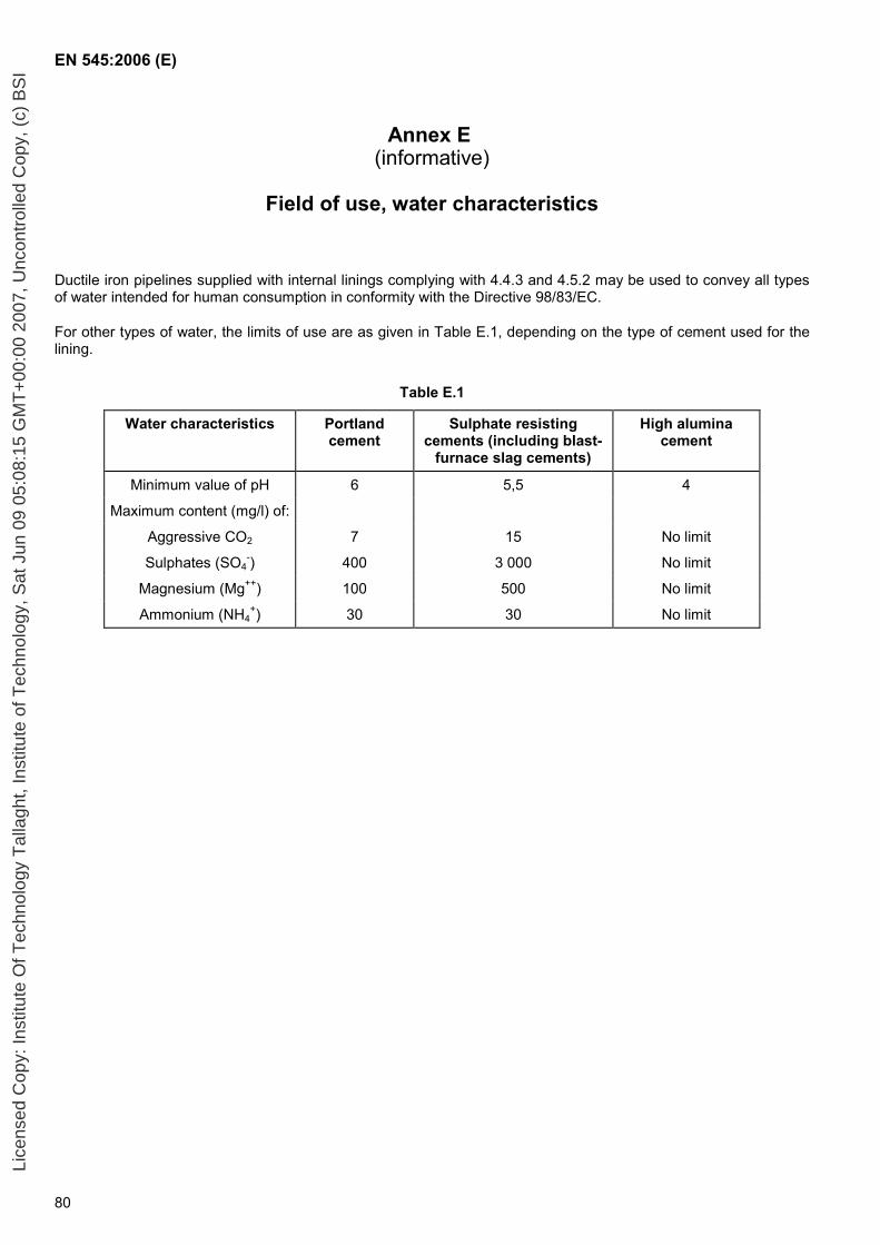
EN 545:2006 (E)
80
Annex E (informative)
Field of use, water characteristics
Ductile iron pipelines supplied with internal linings complying with 4.4.3 and 4.5.2 may be used to convey all types of water intended for human consumption in conformity with the Directive 98/83/EC.
For other types of water, the limits of use are as given in Table E.1, depending on the type of cement used for the lining.
Table E.1
Water characteristics Portland cement
Sulphate resisting cements (including blast-
furnace slag cements)
High alumina cement
Minimum value of pH 6 5,5 4
Maximum content (mg/l) of:
Aggressive CO2 7 15 No limit
Sulphates (SO4-) 400 3 000 No limit
Magnesium (Mg++) 100 500 No limit
Ammonium (NH4+) 30 30 No limit
Lice
nsed
Cop
y: In
stitu
te O
f Tec
hnol
ogy
Tal
lagh
t, In
stitu
te o
f Tec
hnol
ogy,
Sat
Jun
09
05:0
8:15
GM
T+
00:0
0 20
07, U
ncon
trol
led
Cop
y, (
c) B
SI
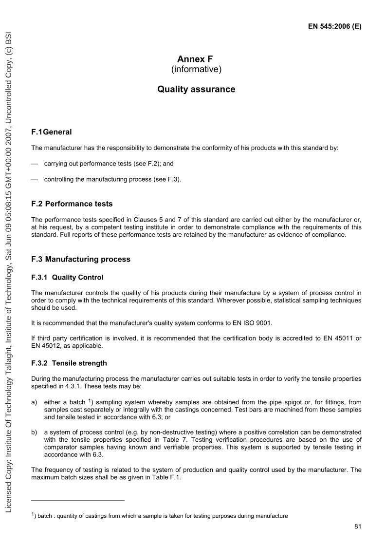
EN 545:2006 (E)
81
Annex F (informative)
Quality assurance
F.1 General
The manufacturer has the responsibility to demonstrate the conformity of his products with this standard by:
carrying out performance tests (see F.2); and
controlling the manufacturing process (see F.3).
F.2 Performance tests
The performance tests specified in Clauses 5 and 7 of this standard are carried out either by the manufacturer or, at his request, by a competent testing institute in order to demonstrate compliance with the requirements of this standard. Full reports of these performance tests are retained by the manufacturer as evidence of compliance.
F.3 Manufacturing process
F.3.1 Quality Control
The manufacturer controls the quality of his products during their manufacture by a system of process control in order to comply with the technical requirements of this standard. Wherever possible, statistical sampling techniques should be used.
It is recommended that the manufacturer's quality system conforms to EN ISO 9001.
If third party certification is involved, it is recommended that the certification body is accredited to EN 45011 or EN 45012, as applicable.
F.3.2 Tensile strength
During the manufacturing process the manufacturer carries out suitable tests in order to verify the tensile properties specified in 4.3.1. These tests may be:
a) either a batch 1) sampling system whereby samples are obtained from the pipe spigot or, for fittings, from samples cast separately or integrally with the castings concerned. Test bars are machined from these samples and tensile tested in accordance with 6.3; or
b) a system of process control (e.g. by non-destructive testing) where a positive correlation can be demonstrated with the tensile properties specified in Table 7. Testing verification procedures are based on the use of comparator samples having known and verifiable properties. This system is supported by tensile testing in accordance with 6.3.
The frequency of testing is related to the system of production and quality control used by the manufacturer. The maximum batch sizes shall be as given in Table F.1.
1) batch : quantity of castings from which a sample is taken for testing purposes during manufacture
Lice
nsed
Cop
y: In
stitu
te O
f Tec
hnol
ogy
Tal
lagh
t, In
stitu
te o
f Tec
hnol
ogy,
Sat
Jun
09
05:0
8:15
GM
T+
00:0
0 20
07, U
ncon
trol
led
Cop
y, (
c) B
SI
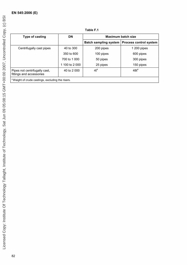
EN 545:2006 (E)
82
Table F.1
Type of casting DN Maximum batch size
Batch sampling system Process control system
Centrifugally cast pipes 40 to 300 200 pipes 1 200 pipes
350 to 600 100 pipes 600 pipes
700 to 1 000 50 pipes 300 pipes
1 100 to 2 000 25 pipes 150 pipes
Pipes not centrifugally cast, fittings and accessories
40 to 2 000 4ta 48ta
a Weight of crude castings, excluding the risers.
Lice
nsed
Cop
y: In
stitu
te O
f Tec
hnol
ogy
Tal
lagh
t, In
stitu
te o
f Tec
hnol
ogy,
Sat
Jun
09
05:0
8:15
GM
T+
00:0
0 20
07, U
ncon
trol
led
Cop
y, (
c) B
SI
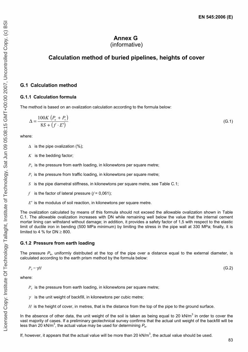
EN 545:2006 (E)
83
Annex G (informative)
Calculation method of buried pipelines, heights of cover
G.1 Calculation method
G.1.1 Calculation formula
The method is based on an ovalization calculation according to the formula below:
( )( )'8
100 te
EfSPPK
⋅++
=∆ (G.1)
where:
∆ is the pipe ovalization (%);
K is the bedding factor;
Pe is the pressure from earth loading, in kilonewtons per square metre;
Pt is the pressure from traffic loading, in kilonewtons per square metre;
S is the pipe diametral stiffness, in kilonewtons per square metre, see Table C.1;
f is the factor of lateral pressure (f = 0,061);
E' is the modulus of soil reaction, in kilonewtons per square metre.
The ovalization calculated by means of this formula should not exceed the allowable ovalization shown in Table C.1. The allowable ovalization increases with DN while remaining well below the value that the internal cement mortar lining can withstand without damage; in addition, it provides a safety factor of 1,5 with respect to the elastic limit of ductile iron in bending (500 MPa minimum) by limiting the stress in the pipe wall at 330 MPa; finally, it is limited to 4 % for DN ≥ 800.
G.1.2 Pressure from earth loading
The pressure Pe, uniformly distributed at the top of the pipe over a distance equal to the external diameter, is calculated according to the earth prism method by the formula below:
Pe = γH (G.2)
where:
Pe is the pressure from earth loading, in kilonewtons per square metre;
γ is the unit weight of backfill, in kilonewtons per cubic metre;
H is the height of cover, in metres, that is the distance from the top of the pipe to the ground surface.
In the absence of other data, the unit weight of the soil is taken as being equal to 20 kN/m3 in order to cover the vast majority of cases. If a preliminary geotechnical survey confirms that the actual unit weight of the backfill will be less than 20 kN/m3, the actual value may be used for determining Pe.
If, however, it appears that the actual value will be more than 20 kN/m3, the actual value should be used.
Lice
nsed
Cop
y: In
stitu
te O
f Tec
hnol
ogy
Tal
lagh
t, In
stitu
te o
f Tec
hnol
ogy,
Sat
Jun
09
05:0
8:15
GM
T+
00:0
0 20
07, U
ncon
trol
led
Cop
y, (
c) B
SI
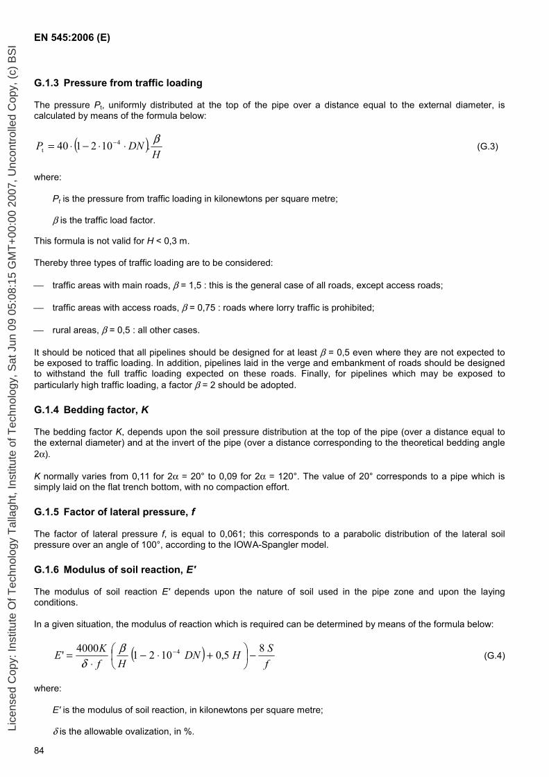
EN 545:2006 (E)
84
G.1.3 Pressure from traffic loading
The pressure Pt, uniformly distributed at the top of the pipe over a distance equal to the external diameter, is calculated by means of the formula below:
( )H
DNP β.102140 4t ⋅⋅−⋅= − (G.3)
where:
Pt is the pressure from traffic loading in kilonewtons per square metre;
β is the traffic load factor.
This formula is not valid for H < 0,3 m.
Thereby three types of traffic loading are to be considered:
traffic areas with main roads, β = 1,5 : this is the general case of all roads, except access roads;
traffic areas with access roads, β = 0,75 : roads where lorry traffic is prohibited;
rural areas, β = 0,5 : all other cases.
It should be noticed that all pipelines should be designed for at least β = 0,5 even where they are not expected to be exposed to traffic loading. In addition, pipelines laid in the verge and embankment of roads should be designed to withstand the full traffic loading expected on these roads. Finally, for pipelines which may be exposed to particularly high traffic loading, a factor β = 2 should be adopted.
G.1.4 Bedding factor, K
The bedding factor K, depends upon the soil pressure distribution at the top of the pipe (over a distance equal to the external diameter) and at the invert of the pipe (over a distance corresponding to the theoretical bedding angle 2α).
K normally varies from 0,11 for 2α = 20° to 0,09 for 2α = 120°. The value of 20° corresponds to a pipe which is simply laid on the flat trench bottom, with no compaction effort.
G.1.5 Factor of lateral pressure, f
The factor of lateral pressure f, is equal to 0,061; this corresponds to a parabolic distribution of the lateral soil pressure over an angle of 100°, according to the IOWA-Spangler model.
G.1.6 Modulus of soil reaction, E'
The modulus of soil reaction E' depends upon the nature of soil used in the pipe zone and upon the laying conditions.
In a given situation, the modulus of reaction which is required can be determined by means of the formula below:
( )fSHDN
HfKE 85,010214000' 4 −
+⋅−
⋅= −β
δ (G.4)
where:
E' is the modulus of soil reaction, in kilonewtons per square metre;
δ is the allowable ovalization, in %. Lice
nsed
Cop
y: In
stitu
te O
f Tec
hnol
ogy
Tal
lagh
t, In
stitu
te o
f Tec
hnol
ogy,
Sat
Jun
09
05:0
8:15
GM
T+
00:0
0 20
07, U
ncon
trol
led
Cop
y, (
c) B
SI
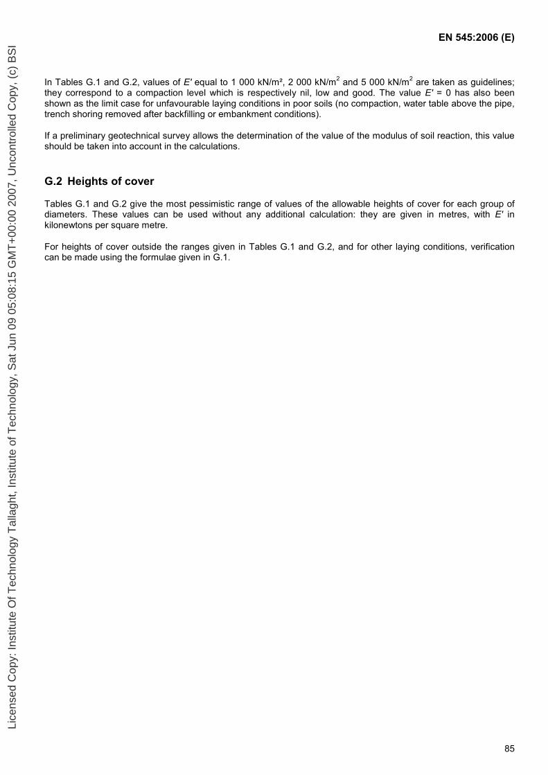
EN 545:2006 (E)
85
In Tables G.1 and G.2, values of E' equal to 1 000 kN/m², 2 000 kN/m2 and 5 000 kN/m2 are taken as guidelines; they correspond to a compaction level which is respectively nil, low and good. The value E' = 0 has also been shown as the limit case for unfavourable laying conditions in poor soils (no compaction, water table above the pipe, trench shoring removed after backfilling or embankment conditions).
If a preliminary geotechnical survey allows the determination of the value of the modulus of soil reaction, this value should be taken into account in the calculations.
G.2 Heights of cover
Tables G.1 and G.2 give the most pessimistic range of values of the allowable heights of cover for each group of diameters. These values can be used without any additional calculation: they are given in metres, with E' in kilonewtons per square metre.
For heights of cover outside the ranges given in Tables G.1 and G.2, and for other laying conditions, verification can be made using the formulae given in G.1.
Lice
nsed
Cop
y: In
stitu
te O
f Tec
hnol
ogy
Tal
lagh
t, In
stitu
te o
f Tec
hnol
ogy,
Sat
Jun
09
05:0
8:15
GM
T+
00:0
0 20
07, U
ncon
trol
led
Cop
y, (
c) B
SI
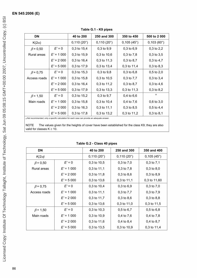
EN 545:2006 (E)
86
Table G.1 - K9 pipes
DN 40 to 200 250 and 300 350 to 450 500 to 2 000
K(2α) 0,110 (20°) 0,110 (20°) 0,105 (45°) 0,103 (60°)
β = 0,50 E’ = 0 0,3 to 15,4 0,3 to 9,9 0,3 to 6,9 0,3 to 2,2
Rural areas E’ = 1 000 0,3 to 15,9 0,3 to 10,6 0,3 to 7,8 0,3 to 3,5
E’ = 2 000 0,3 to 16,4 0,3 to 11,3 0,3 to 8,7 0,3 to 4,7
E’ = 5 000 0,3 to 17,9 0,3 to 13,4 0,3 to 11,4 0,3 to 8,3
β = 0,75 E’ = 0 0,3 to 15,3 0,3 to 9,8 0,3 to 6,8 0,5 to 2,0
Access roads E’ = 1 000 0,3 to 15,8 0,3 to 10,5 0,3 to 7,7 0,3 to 3,4
E’ = 2 000 0,3 to 16,4 0,3 to 11,2 0,3 to 8,7 0,3 to 4,6
E’ = 5 000 0,3 to 17,9 0,3 to 13,3 0,3 to 11,3 0,3 to 8,2
β = 1,50 E’ = 0 0,3 to 15,2 0,3 to 9,7 0,4 to 6,6 a
Main roads E’ = 1 000 0,3 to 15,8 0,3 to 10,4 0,4 to 7,6 0,6 to 3,0
E’ = 2 000 0,3 to 16,3 0,3 to 11,1 0,3 to 8,5 0,5 to 4,4
E’ = 5 000 0,3 to 17,8 0,3 to 13,2 0,3 to 11,2 0,3 to 8,1 a Not recommended; only a specific calculation for each case can provide an adequate answer.
NOTE The values given for the heights of cover have been established for the class K9; they are also valid for classes K ≥ 10.
Table G.2 - Class 40 pipes
DN 40 to 200 250 and 300 350 and 400
K(2α) 0,110 (20°) 0,110 (20°) 0,105 (45°)
β = 0,50 E’ = 0 0,3 to 10,5 0,3 to 7,0 0,3 to 7,1
Rural areas E’ = 1 000 0,3 to 11,1 0,3 to 7,8 0,3 to 8,0
E’ = 2 000 0,3 to 11,8 0,3 to 8,6 0,3 to 8,9
E’ = 5 000 0,3 to 13,6 0,3 to 11,1 0,3 to 11,60
β = 0,75 E’ = 0 0,3 to 10,4 0,3 to 6,9 0,3 to 7,0
Access roads E’ = 1 000 0,3 to 11,1 0,3 to 7,7 0,3 to 7,9
E’ = 2 000 0,3 to 11,7 0,3 to 8,6 0,3 to 8,8
E’ = 5 000 0,3 to 13,6 0,3 to 11,0 0,3 to 11,5
β = 1,50 E’ = 0 0,3 to 10,3 0,5 to 6,7 0,5 to 6,8
Main roads E’ = 1 000 0,3 to 10,9 0,4 to 7,6 0,4 to 7,8
E’ = 2 000 0,3 to 11,6 0,4 to 8,4 0,4 to 8,7
E’ = 5 000 0,3 to 13,5 0,3 to 10,9 0,3 to 11,4
Lice
nsed
Cop
y: In
stitu
te O
f Tec
hnol
ogy
Tal
lagh
t, In
stitu
te o
f Tec
hnol
ogy,
Sat
Jun
09
05:0
8:15
GM
T+
00:0
0 20
07, U
ncon
trol
led
Cop
y, (
c) B
SI
EN 545:2006 (E)
87
Bibliography
[1] EN 1333:2006, Flanges and their joints — Pipework components — Definition and selection of PN.
[2] EN 1514, Flanges and their joints — Dimensions of gaskets for PN-designated flanges.
[3] EN 14628, Ductile iron pipes, fittings and accessories — External polyethylene coating for pipes — Requirements and test methods
[4] EN 15189, Ductile iron pipes, fittings and accessories — External polyurethane coating for pipes — Requirements and test methods
[5] EN 45011, General requirements for bodies operating product certification systems (ISO/IEC Guide 65:1996)
[6] EN 45012, General requirements for bodies operating assessment and certification/registration of quality systems (ISO/IEC Guide 62:1996)
[7] EN ISO 6708:1995, Pipework components — Definition and selection of DN (nominal size) (ISO 6708:1995).
[8] EN ISO 9001:2000, Quality management systems – Requirements (ISO 9001:2000).
[9] ISO 2531, Ductile iron pipes, fittings, accessories and their joints for water or gas applications.
[10] EEC Directive 98/83/EC of 3 November 1998, known as “Drinking Water Directive”.
[11] EEC Directive 89/106/EEC of 12 December 1989, known as “Construction Products Directive”.
[12] EN 14901, Ductile iron pipes, fittings and accessories — Epoxy coating (heavy duty) of ductile iron fittings and accessories — Requirements and test methods
[13] prEN 15542, Ductile iron pipes, fittings and accessories — External cement mortar coating for pipes — Requirements and test methods
Lice
nsed
Cop
y: In
stitu
te O
f Tec
hnol
ogy
Tal
lagh
t, In
stitu
te o
f Tec
hnol
ogy,
Sat
Jun
09
05:0
8:15
GM
T+
00:0
0 20
07, U
ncon
trol
led
Cop
y, (
c) B
SI
BS EN 545:2006
BSI389 Chiswick High RoadLondonW4 4AL
BSI — British Standards InstitutionBSI is the independent national body responsible for preparing British Standards. It presents the UK view on standards in Europe and at the international level. It is incorporated by Royal Charter.
Revisions
British Standards are updated by amendment or revision. Users of British Standards should make sure that they possess the latest amendments or editions.
It is the constant aim of BSI to improve the quality of our products and services. We would be grateful if anyone finding an inaccuracy or ambiguity while using this British Standard would inform the Secretary of the technical committee responsible, the identity of which can be found on the inside front cover. Tel: +44 (0)20 8996 9000. Fax: +44 (0)20 8996 7400.
BSI offers members an individual updating service called PLUS which ensures that subscribers automatically receive the latest editions of standards.
Buying standards
Orders for all BSI, international and foreign standards publications should be addressed to Customer Services. Tel: +44 (0)20 8996 9001. Fax: +44 (0)20 8996 7001. Email: [email protected]. Standards are also available from the BSI website at http://www.bsi-global.com.
In response to orders for international standards, it is BSI policy to supply the BSI implementation of those that have been published as British Standards, unless otherwise requested.
Information on standards
BSI provides a wide range of information on national, European and international standards through its Library and its Technical Help to Exporters Service. Various BSI electronic information services are also available which give details on all its products and services. Contact the Information Centre. Tel: +44 (0)20 8996 7111. Fax: +44 (0)20 8996 7048. Email: [email protected].
Subscribing members of BSI are kept up to date with standards developments and receive substantial discounts on the purchase price of standards. For details of these and other benefits contact Membership Administration. Tel: +44 (0)20 8996 7002. Fax: +44 (0)20 8996 7001. Email: [email protected].
Information regarding online access to British Standards via British Standards Online can be found at http://www.bsi-global.com/bsonline.
Further information about BSI is available on the BSI website at http://www.bsi-global.com.
Copyright
Copyright subsists in all BSI publications. BSI also holds the copyright, in the UK, of the publications of the international standardization bodies. Except as permitted under the Copyright, Designs and Patents Act 1988 no extract may be reproduced, stored in a retrieval system or transmitted in any form or by any means – electronic, photocopying, recording or otherwise – without prior written permission from BSI.
This does not preclude the free use, in the course of implementing the standard, of necessary details such as symbols, and size, type or grade designations. If these details are to be used for any other purpose than implementation then the prior written permission of BSI must be obtained.
Details and advice can be obtained from the Copyright & Licensing Manager. Tel: +44 (0)20 8996 7070. Fax: +44 (0)20 8996 7553. Email: [email protected].
Lice
nsed
Cop
y: In
stitu
te O
f Tec
hnol
ogy
Tal
lagh
t, In
stitu
te o
f Tec
hnol
ogy,
Sat
Jun
09
05:0
8:15
GM
T+
00:0
0 20
07, U
ncon
trol
led
Cop
y, (
c) B
SI