ductile-iron pipe and fittings - american water works ... · 2 ductile-iron pipe and fittings ......
TRANSCRIPT
Ductile-Iron Pipe
and Fittings
AWWA MANUAL M41
Third Edition
M41 Book.indb 1 3/18/2009 3:30:55 PM
Copyright © 2009 American Water Works Association. All Rights Reserved.
Contents
List of Figures, vii
List of Tables, xi
Preface, xiii
Acknowledgments, xv
General Information and History Chapter 1 ...................................................... 1
1.1 History, 11.2 Applications and Appurtenances, 31.3 Ductile Iron Pipe Research Association (DIPRA), 5
Applicable Standards Chapter 2 ............................................................................ 7
2.1 Related Standards, 72.2 Other Reference Standards and Special Products, 10References, 10
Manufacturing and Testing Chapter 3 ............................................................... 13
3.1 Manufacturing, 133.2 Testing, 173.3 Fittings Testing, 19References, 20
DesignChapter 4 ....................................................................................................... 21
4.1 Background, 214.2 Major Design Criteria and Formulas, 224.3 Truck Loads on Pipe Buried at Shallow Depths, 384.4 Thickness Design for Ductile-Iron Pipe Under Railroads, 434.5 Thickness Design for Ductile-Iron Pipe on Supports, 454.6 Special Use Considerations, 57References, 58
Pipe Joints Chapter 5 ............................................................................................. 59
5.1 Introduction, 595.2 Joints, 595.3 Gaskets, 645.4 Joint Accessories, 645.5 Permeation, 65References, 66
iii
M41 Book.indb 3 3/18/2009 3:30:56 PM
Copyright © 2009 American Water Works Association. All Rights Reserved.
Ductile- and Gray-Iron Fittings Chapter 6 ........................................................ 67
6.1 Introduction, 676.2 Fittings, 676.3 Special Service Requirements, 70References, 71
Valves and Hydrants Chapter 7 ............................................................................ 73
7.1 Introduction, 737.2 Types of Valves and Hydrants, 737.3 Installation, 767.4 Operation, 767.5 Good Practice, 77References, 77
Thrust Restraint Design for Ductile-Iron Pipe Chapter 8 ............................. 79
8.1 Introduction, 798.2 The Thrust Force, 818.3 Thrust Blocks, 828.4 Restrained Joints, 858.5 Restraint Design for Vertical Bends, Tees, Reducers, and Dead Ends, 938.6 Encroaching Restrained Lengths, 978.7 Restrained Length, 998.8 Select Backfill Considerations, 998.9 Combining Thrust Blocks and Restrained Joints, 1018.10 Pipe in a Casing, 1018.11 Future Excavations, 1018.12 Deflected Unrestrained Ductile-Iron Pipe Joints, 1018.13 Computer Program, 1028.14 Restrained Length Calculation Procedure, 1028.15 Tabular Values for Fs, (Fs)b, and Rs, 1038.16 Restrained Joint Design Tables for Horizontal Bends, 104References, 147
Interior Linings and Hydraulics Chapter 9 .................................................... 149
9.1 Cement–Mortar-Lined Ductile-Iron Pipe, 1499.2 Flow Characteristics of Ductile-Iron Pipe, 1539.3 Pumping Cost, 155References, 164
External Corrosion Protection Chapter 10 ..................................................... 165
10.1 Introduction, 16510.2 Basic Corrosion Theory, 16610.3 Corrosion Resistance of Ductile-Iron Pipe, 17210.4 Evaluation of Corrosive Soils, 173
iv
M41 Book.indb 4 3/18/2009 3:30:56 PM
Copyright © 2009 American Water Works Association. All Rights Reserved.
10.5 Buried Service—Corrosion Control, 17510.6 Exposed Service Conditions, 18810.7 Submerged Service Conditions and Control, 192References, 193
Installation of Ductile-Iron Pipe Chapter 11 .................................................. 195
11.1 Introduction, 19511.2 Pipe Inspection, Storage, Handling, and Delivery, 19511.3 Trenching, Embedment, Pipe Installation, and Backfilling, 19711.4 Pipeline Accessories, 20911.5 Thrust Restraint, 21211.6 Flushing, Field Testing, and Disinfection, 21211.7 Service Taps, 21511.8 Highway and Railroad Crossings, 22011.9 Trenchless Applications, 22011.10 Subaqueous Installations, 22011.11 Other Installations, 222References, 225
Trenchless Installation— Chapter 12 Horizontal Directional Drilling ......................................................... 227
12.1 Introduction, 22712.2 Predesign Investigation, 22912.3 HDD Assembly Methods for Flexible Restrained-Joint
Ductile-Iron Pipe, 23012.4 Survey, 23212.5 Subsurface Analysis, 23212.6 Borepath Design, 23412.7 Pipe Design: Introduction, 23512.8 Testing and Service Pressure/Loads, 23812.9 Thermal Expansion/Contraction and Pulling Load “Recoil,” 239References, 239
Guidelines for Purchase of Pipe and Fittings Chapter 13 ............................ 241
13.1 General, 24113.2 Ductile-Iron Pipe, 24313.3 Ductile-Iron and Gray-Iron Fittings and Specials, 24413.4 Polyethylene Encasement, 244References, 245
Appendix A Illustrations of Proprietary Joints for Ductile-Iron Pipe and Fittings ...................................................................................... 247
Index . . . . . . . . . . . . . . . . . . . . . . . . . . . . . . . . . . . . . . . . . . . . . . . . . . . . . . . . . . . . . . . . . . . . . . . . . . . . . . . . . . . . . . . . . . . . . . . . . . . . . . 253
AWWA Manuals . . . . . . . . . . . . . . . . . . . . . . . . . . . . . . . . . . . . . . . . . . . . . . . . . . . . . . . . . . . . . . . . . . . . . . . . . . . . . . . . . . . . . . . 259
v
M41 Book.indb 5 3/18/2009 3:30:56 PM
Copyright © 2009 American Water Works Association. All Rights Reserved.
©1
AWWA MANUAL M41
Chapter 1
General Information and History
This manual provides the user with both technical and general information to aid in the design, specification, procurement, installation, and understanding of ductile-iron pipe.
The manual describes ductile-iron pipe and fitting products, appurtenances, and their application to practical installations, whether of a standard or special nature.
1.1 HIsTory ___________________________________________________________________________1.1.1 GeneralThe history of pipe parallels that of civilization. The earliest communities were estab-lished near water sources that later became inadequate as populations increased. Hy-draulic engineering was born of the necessity to transport water closer to the point of use. From ancient Babylon’s clay pipes, to the underground tunnels of ancient Greece, to the aqueducts of the Roman Empire, to the cast-iron mains of Versailles, France, to today’s modern pipe, the search for an affordable piping material with reliable strength and durability evolved. Cast-iron pipe rapidly became the standard material for wa-ter distribution mains. Today, in the United States and Canada alone, there are more than 622 utilities that have had cast-iron distribution mains with continuous service records of more than 100 years, and 23 for 150 years or more.
The production of iron pipe most likely developed from or coincided with the man-ufacture of cannons as early as the year 1313. There is an official record of cast-iron pipe being manufactured at Siegerland, Germany, in 1455 for installation at the Dil-lenberg Castle.
In 1664, King Louis XIV of France ordered the construction of a cast-iron pipe main to extend 15 mi (24 km) from a pumping station at Marly-on-Seine to Versailles to supply water for the fountains and town. This cast-iron pipe provided continuous service for more than 330 years. When the line was originated, the production of iron required the use of expensive charcoal for the reduction of the iron ore. By 1738, success
M41 Book.indb 1 3/18/2009 3:30:57 PM
Copyright © 2009 American Water Works Association. All Rights Reserved.
©2 DUCTILE-IRON PIPE AND FITTINGS
had been achieved in producing lower-cost iron by using coke instead of charcoal. Fol-lowing this success, the more progressive cities began to install cast-iron mains.
The use of cast-iron pipe was introduced in the United States in the early 1800s. Since that time, various other piping materials have been offered for water distribu-tion. However, waterworks engineers continued to use cast iron until ductile iron, a stronger and equally durable piping material, became available.
1.1.2 Development of JointsFlanged . Originally, cast-iron pipe was made with flanged joints, using lead
gaskets. Improved joints of this type are still used for many aboveground plant instal-lations and other specialized applications.
Bell and spigot . The bell and spigot joint was developed in 1785 and was used extensively until the 1950s. This joint was assembled by caulking yarn or braided hemp into the base of the annular bell cavity and then pouring molten lead into the remaining space inside the bell. On solidification, the lead was compacted by caulk-ing, thus effecting a watertight seal. Materials other than lead have also been used to confine yarn or hemp in the base of the bell cavity.
Mechanical joint . The mechanical joint was developed for gas industry use in the late 1920s but has since been used extensively in the water industry. This joint has standardized dimensions and uses the basic principle of the stuffing box and gland, with a rubber gasket being compressed by the gland.
Roll-on joint . The roll-on joint was developed in 1937 and was used for approxi-mately 20 years before its manufacture was discontinued. Assembly of this joint involved a compressed rubber gasket rolled under a restriction ring, followed by caulked square braided jute. The remainder of the joint was packed with a bituminous compound.
Push-on joint . The push-on joint was developed in 1956 and represented an important advancement in the water distribution field. This joint consists of a single rubber gasket placed in a groove inside the socket at the bell end of the pipe. After lubricating the joint in accordance with the manufacturer’s instructions, the plain end of the pipe is pushed past the gasket, compressing it and forming a seal that is tight versus high internal pressures, vacuum, and external water head. Assembly of the push-on joint is simple and fast. Large bell holes are not required for this joint, and it can be assembled under wet-trench conditions or even under water.
Special joints . Several special joints are available. These joints include ball and socket for subaqueous crossings, plain-end coupled, threaded and coupled, and other variations of restrained joints.
A more detailed description of the joints used with ductile-iron pipe is found in chapter 5 of this manual.
1.1.3 Development of Ductile-Iron PipeThe advent of ductile-iron pipe in 1948 was one of the most significant developments in the pressure pipe industry. Quickly recognized as a pipe material with all the good qual-ities of gray cast-iron pipe plus additional strength and ductility, it was first used for special and severe conditions of high pressure, water hammer, and excessive external loads. For more than 50 years, it has proved to be virtually trouble and maintenance free as an underground pressure pipe material, and today it is used in the transporta-tion of raw and potable water, sewage, slurries, and process chemicals. The strength and rugged durability of ductile iron results in a high level of operational reliability. For these reasons, it rapidly replaced gray cast iron in the marketplace and is the iron piping material now specified by waterworks professionals.
M41 Book.indb 2 3/18/2009 3:30:57 PM
Copyright © 2009 American Water Works Association. All Rights Reserved.
©GENERAL INFORMATION AND HISTORY 3
1.1.4 Manufacture of Ductile-Iron PipeThe centrifugal casting methods used in manufacturing ductile-iron pipe have been in the process of commercial development and refinement since 1925. The steady im-provements that led to the present state of the art have been covered by hundreds of patents and technical papers, and represent the ingenuity of many dedicated engi-neers, metallurgists, and foundry personnel. A detailed description of the metallurgical and physical characteristics of ductile-iron pipe and fittings produced to ANSI*/AWWA standards is in chapter 3 of this manual.
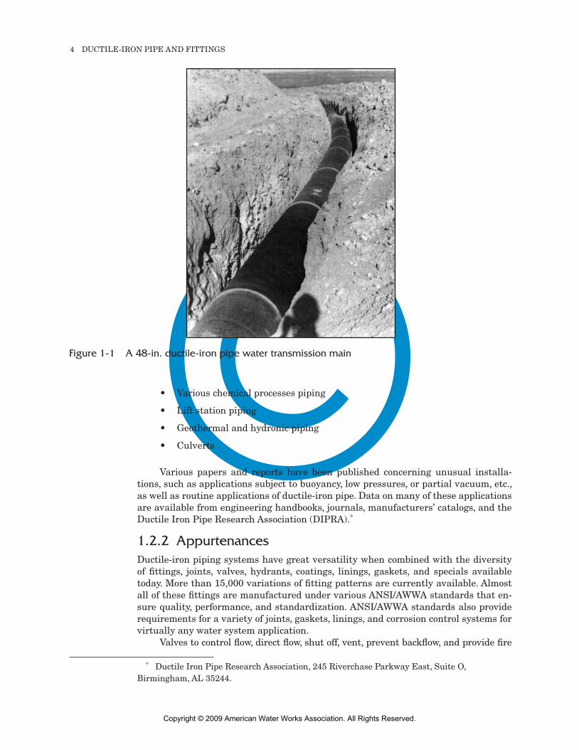
1.2 APPlICATIons AnD APPurTenAnCes ________________________________Ductile-iron pipe and related products convey water from its source to its point of use through the myriad stages of storage, transmission (Figure 1-1), filtration, pumping, chemical treatment, and distribution. After the water is used, ductile-iron pipe plays a similar part in collecting, conveying, pumping, treating, reusing, and discharging wastewater in the never-ending water cycle. Ductile-iron pipe has long been noted for its long-term economy, performance, reliability, and proven record in serving the pub-lic’s health, safety, and daily water needs.
1.2.1 ApplicationsDuctile-iron pipe that meets the requirements of various pertinent AWWA standards is used for numerous applications, some of which are
Raw water supply lines•
Transmission mains•
Distribution mains•
Fire mains•
Sewer force mains•
Subaqueous crossings•
Air service•
Pump station piping•
Intake lines•
Brine handling•
Acid handling•
Sulfur handling•
Gravity sewers•
Treatment plant piping•
Outfall mains•
Reclaimed water lines•
Penstocks•
* American National Standards Institute, 25 W. 43rd St., Fourth Floor, New York, NY 10036-7406.
M41 Book.indb 3 3/18/2009 3:30:58 PM
Copyright © 2009 American Water Works Association. All Rights Reserved.
©4 DUCTILE-IRON PIPE AND FITTINGS
A 48-in. ductile-iron pipe water transmission mainFigure 1-1
Various chemical processes piping•
Lift station piping•
Geothermal and hydronic piping•
Culverts•
Various papers and reports have been published concerning unusual installa-tions, such as applications subject to buoyancy, low pressures, or partial vacuum, etc., as well as routine applications of ductile-iron pipe. Data on many of these applications are available from engineering handbooks, journals, manufacturers’ catalogs, and the Ductile Iron Pipe Research Association (DIPRA).*
1.2.2 AppurtenancesDuctile-iron piping systems have great versatility when combined with the diversity of fittings, joints, valves, hydrants, coatings, linings, gaskets, and specials available today. More than 15,000 variations of fitting patterns are currently available. Almost all of these fittings are manufactured under various ANSI/AWWA standards that en-sure quality, performance, and standardization. ANSI/AWWA standards also provide requirements for a variety of joints, gaskets, linings, and corrosion control systems for virtually any water system application.
Valves to control flow, direct flow, shut off, vent, prevent backflow, and provide fire
* Ductile Iron Pipe Research Association, 245 Riverchase Parkway East, Suite O, Birmingham, AL 35244.
M41 Book.indb 4 3/18/2009 3:30:58 PM
Copyright © 2009 American Water Works Association. All Rights Reserved.
©GENERAL INFORMATION AND HISTORY 5
protection are available in joints and types compatible with ductile-iron pipe systems. These valves and hydrants are manufactured according to ANSI/AWWA standards, as well as various insurance and independent test laboratory requirements in some cases.
Many special applications can be provided in ductile-iron pipe systems, such as restrained joints, flexible joint subaqueous pipe, base-mounted fittings, bonded joints, self-locking gaskets, epoxy or other special linings, and polyethylene encasement.
1.3 DuCTIle Iron PIPe reseArCH AssoCIATIon (DIPrA) __________DIPRA, formerly the Cast Iron Pipe Research Association or CIPRA, is a nonprofit organization whose members are manufacturers of ductile-iron pressure pipe. Since 1915, the association has provided engineering and research information on cast- and ductile-iron products by
Participating in national and international standards development by ANSI, •AWWA, ASTM International*, American Society of Mechanical Engineers (ASME),† NACE International (NACE),‡ National Fire Protection Association (NFPA),§ and the International Organization for Standardization (ISO)**
Presenting engineering seminars on design, pipeline construction, corrosion •control, and special applications and problems
Providing field services, such as soil investigations, flow tests, and consulta-•tion with engineers on piping problems, including pipe and system design
Publishing research and engineering information in technical papers, bro-•chures, and manuals
* ASTM International, 100 Barr Harbor Dr., West Conshohocken, PA 19428-2959.† American Society of Mechanical Engineers, 345 E. 47th St., New York, NY 10017.‡ NACE International, 1440 South Creek Dr., Houston, TX 77084-4906.§ National Fire Protection Association, 1 Batterymarch Park, Quincy, MA 02269-9101.** ISO standards are available through ANSI, 25 W. 43rd St., Fourth Floor, New York, NY
10036-7406.
M41 Book.indb 5 3/18/2009 3:30:58 PM
Copyright © 2009 American Water Works Association. All Rights Reserved.
©7
AWWA MAnuAl M41
Chapter 2
Applicable standards
AWWA standards for cast-iron pipe date back to 1890. Today, AWWA publishes 11 standards related to ductile-iron pipe, ductile- and gray-iron fittings, and related items, including joint materials, design, and installation. These standards are individually revised, updated, and published on a five-year basis. Other organizations that publish standards related to ductile-iron pipe and fittings include ASTM* and the Interna-tional Organization for Standardization (ISO).†
2.1 relATeD sTAnDArDs __________________________________________________________The following describes the current editions of standards related to ductile-iron pipe and fittings.
2.1.1 AnsI/AWWA C104/A21.4,1 standard for Cement–Mortar lining for Ductile-Iron Pipe and FittingsFirst used in 1922 in Charleston, S.C., cement–mortar lining has proved to be a very effective means of preventing tuberculation and maintaining a high flow coefficient in both gray- and ductile-iron pipe and fittings. As a result, ductile-iron pipe as well as gray- and ductile-iron fittings used for potable water applications are normally fur-nished with a cement–mortar lining unless otherwise specified by the purchaser.
2.1.2 AnsI/AWWA C105/A21.5,2 standard for Polyethylene encasement for Ductile-Iron Pipe systemsLoose polyethylene encasement was first used experimentally in the United States in 1951 to protect cast-iron pipe in corrosive environments. The first field installation of polyethylene encasement of cast-iron pipe in an operating water system was com-pleted in 1958. Since that time, thousands of installations have been made in severely
* ASTM International, 100 Barr Harbor Drive, West Conshohocken, PA 19428-2959.
† ISO standards are available through the American National Standards Institute, 25 W. 43rd St., Fourth Floor, New York, NY 10036-7406.
M41 Book.indb 7 3/18/2009 3:30:58 PM
Copyright © 2009 American Water Works Association. All Rights Reserved.
©8 DUCTILE-IRON PIPE AND FITTINGS
corrosive soils throughout the United States in pipe sizes ranging from 3 in. to 64 in. (76 mm to 1,600 mm) in diameter. This history of usage, coupled with extensive and ongoing research, has clearly demonstrated the efficacy of polyethylene encasement as a corrosion protection means for both gray- and ductile-iron pipe. Polyethylene encase-ment is also used as a soil corrosion preventive in a number of other countries, and an International Standard for Polyethylene Sleeving (ISO-8180)3 was adopted after the procedure was developed in the United States. There is also an ASTM A6744 cover-ing polyethylene encasement for ductile-iron pipe, which closely parallels the ANSI/AWWA standard.
The ANSI/AWWA standard describes material requirements, effects of sun-light, tube size or sheet width, and installation methods. Appendix A to the standard describes a method for evaluating potentially corrosive environments to gray- and duc-tile-iron pipe to determine when polyethylene encasement should be used.
2.1.3 AnsI/AWWA C110/A21.10,5 standard for Ductile-Iron and Gray-Iron FittingsThis standard describes requirements and dimensions of ductile-iron and gray-iron fittings in mechanical, flanged, and push-on joint configurations. The standard further describes markings, certification requirements, inspection, coatings and linings, and acceptance tests. Detailed tables include data on thickness requirements, joint dimen-sions, gasket seats, and laying lengths.
2.1.4 AnsI/AWWA C111/A21.11,6 standard for rubber- Gasket Joints for Ductile-Iron Pressure Pipe and FittingsThis standard describes rubber-gasketed joints for gray- and ductile-iron pipe and fit-tings with mechanical joints, push-on joints, or modified mechanical or push-on joints. The standard includes detailed requirements for each joint type, such as dimensions, tolerances, lubrication, gaskets, marking, and packing. Also described in the standard are requirements for glands, gaskets, and bolts, along with tables designating toleranc-es, dimensions, physical specifications, thread length and depth, bolt sizes, and torque ranges. Notes on installing mechanical joints, including recommended bolt torques to be applied, are in the appendix of the standard.
2.1.5 AnsI/AWWA C115/A21.15,7 standard for Flanged Ductile-Iron Pipe With Ductile-Iron or Gray-Iron Threaded FlangesThis standard pertains to flanged ductile-iron pipe with either gray- or ductile-iron threaded flanges. Tables are provided that describe required thickness, working pres-sure, class of pipe, and weights and dimensions. The standard describes inspection and certification by the manufacturer, acceptance on delivery, flanges to be used, fabrica-tion procedures, coatings, linings, and markings. A table of flange gasket dimensions is also included in the appendix.
M41 Book.indb 8 3/18/2009 3:30:59 PM
Copyright © 2009 American Water Works Association. All Rights Reserved.
©APPLICABLE STANDARDS 9
2.1.6 AnsI/AWWA C116/A21.16,8 standard for Protective Fusion-Bonded epoxy Coatings for the Interior and exterior surfaces of Ductile-Iron and Gray-Iron FittingsThis standard describes protective fusion-bonded epoxy coatings for the interior and exterior surfaces of ductile-iron and gray-iron fittings used for water, wastewater, and reclaimed water systems. The standard describes the material, application, and per-formance requirements for these coatings. It does not describe coatings agreed on be-tween the purchaser and the manufacturer for special service conditions, such as salt water, sewers, acid, high temperature, and so forth.
2.1.7 AnsI/AWWA C150/A21.50,9 standard for Thickness Design of Ductile-Iron PipeThe thickness design of ductile-iron pipe is presented in this standard, along with an example problem that illustrates proper application of the design method. Tables and charts are also provided that describe earth loads, truck loads, trench loads, design values for standard laying conditions, casting tolerances, diameter–thickness ratios, and other pertinent design parameters.
2.1.8 AnsI/AWWA C151/A21.51,10 standard for Ductile-Iron Pipe, Centrifugally CastThis standard describes the manufacture of ductile-iron pipe for water, wastewater, and reclaimed water systems with push-on joints and mechanical joints. It includes general requirements, inspection and certification by the manufacturer, inspection-delivery-acceptance by the purchaser, tolerances or permitted variations, coatings and linings, testing requirements, marking and weighing of pipe, foundry records required, defective specimens and retests, and pipe rejection criteria. Tables are provided for standard thickness requirements, rated working pressure, maximum depth of cover, and standard dimensions and weights of push-on joint and mechanical joint ductile-iron pipe. Appendix A of this standard consists of two tables that show pipe thicknesses required for various tap sizes.
2.1.9 AnsI/AWWA C153/A21.53,11 standard for Ductile-Iron Compact Fittings for Water serviceA recent development in the industry is the introduction of compact fittings designed to use the attendant strength of ductile iron. Compact fittings are alternatives to those covered by ANSI/AWWA C110/A21.10.
This standard describes compact ductile-iron fittings ranging in size from 3 in. through 48 in. (76 mm through 1,219 mm), with mechanical joints, push-on joints, or such other joints (except flanged joints) as specified, and 54 in. through 64 in. (1,400 mm through 1,600 mm) with push-on or flanged joints. The information provided closely parallels that given in ANSI/AWWA C110/A21.10.
M41 Book.indb 9 3/18/2009 3:30:59 PM
Copyright © 2009 American Water Works Association. All Rights Reserved.
©10 DUCTILE-IRON PIPE AND FITTINGS
2.1.10 AnsI/AWWA C600,12 standard for Installation of Ductile-Iron Water Mains and Their AppurtenancesThis standard pertains to the installation of ductile-iron water mains and their appur-tenances, and describes such topics as inspection, handling, storage, pipe installation, joint assembly, backfilling, hydrant installation, thrust restraint, flushing, pressure and leakage tests, highway and railroad crossings, and tapping. Many tables and dia-grams are provided for clarification.
2.1.11 AnsI/AWWA C606,13 standard for Grooved and shouldered JointsThis standard, describing grooved and shouldered joints, includes sections on general requirements, materials, general design, inspection, testing, and rejection. Tables and illustrations provide grooving dimensions, coupling and joint configurations, and other pertinent information.
2.2 oTHer reFerenCe sTAnDArDs AnD sPeCIAl ProDuCTs ___In addition to the ANSI/AWWA standards described previously, the following stan-dards are commonly used by the industry:
ASTM A377• 14—Standard Index of Specifications for Ductile Iron Pressure Pipe
ASTM A674—Standard Practice for Polyethylene Encasement for Ductile •Iron Piping for Water or Other Liquids
ASTM A716• 15—Standard Specification for Ductile Iron Culvert Pipe
ASTM A746• 16—Standard Specification for Ductile Iron Gravity Sewer Pipe
Because of innovations in research, design, and manufacturing methods, and in response to changing needs of the marketplace, manufacturers of ductile-iron pipe and related products also offer other products that are not currently included in ANSI/AWWA standards. These products include restrained joints, bell-less joints, special linings and coatings, special fittings, and welded-on bosses and outlets. Many of these products meet applicable parts of current standards, and some may be included in future revisions. Information on some of these products is included in this manual. For more details, consult the manufacturers.
reFerenCes ______________________________________________________________________________
Standard for Cement–Mortar Lining 1. for Ductile-Iron Pipe and Fittings. ANSI/AWWA Standard C104/A21.4. Denver, Colo.: American Water Works Association. Standard for Polyethylene Encasement for 2. Ductile-Iron Pipe Systems. ANSI/AWWA Standard C105/A21.5. Denver, Colo.: American Water Works Association. International Standard for Polyethylene 3. Sleeving. ISO-8180. Geneva, Switzerland.
Standard Practice for Polyethylene 4. Encasement for Ductile Iron Piping for Water or Other Liquids. ASTM A674. West Conshohocken, Pa.: ASTM International. Standard for Ductile-Iron and Gray-Iron 5. Fittings. ANSI/AWWA C110/A21.10. Denver, Colo.: American Water Works Association. Standard for Rubber-Gasket Joints for 6. Ductile-Iron Pressure Pipe and Fittings. ANSI/AWWA C111/A21.11. Denver, Colo.: American Water Works Association.
M41 Book.indb 10 3/18/2009 3:30:59 PM
Copyright © 2009 American Water Works Association. All Rights Reserved.
©APPLICABLE STANDARDS 11
Standard for Flanged Ductile-Iron Pipe 7. with Ductile-Iron or Gray Iron Threaded Flanges. ANSI/AWWA C115/A21.15. Denver, Colo.: American Water Works Association. Standard for Protective Fusion-Bonded 8. Epoxy Coatings for the Interior and Exterior Surfaces of Ductile-Iron and Gray-Iron Fittings. ANSI/AWWA C116-A21.16. Denver, Colo.: American Water Works Association. Standard for Thickness Design of Ductile-9. Iron Pipe. ANSI/AWWA C150/A21.50. Denver, Colo.: American Water Works Association. Standard for Ductile-Iron Pipe, 10. Centrifugally Cast. ANSI/AWWA C151/A21.51. Denver, Colo.: American Water Works Association. Standard for Ductile-Iron Compact 11. Fittings for Water Service. ANSI/AWWA C153/A21.53. Denver, Colo.: American Water Works Association.
Standard for Installation of Ductile-Iron 12. Water Mains and Their Appurtenances. ANSI/AWWA C600. Denver, Colo.: American Water Works Association. Standard for Grooved and Shouldered 13. Joints. ANSI/AWWA C606. Denver, Colo.: American Water Works Association. Standard Index of Specifications for 14. Ductile Iron Pressure Pipe. ASTM A377. West Conshohocken, Pa.: ASTM International. Standard Specification for Ductile 15. Iron Culvert Pipe. ASTM A716. West Conshohocken, Pa.: ASTM International. Standard Specification for Ductile Iron 16. Gravity Sewer Pipe. ASTM A746. West Conshohocken, Pa.: ASTM International.
M41 Book.indb 11 3/18/2009 3:30:59 PM
Copyright © 2009 American Water Works Association. All Rights Reserved.