ductile iron flanged fittings - mcwane · ductile iron flanged fittings ansi/awwa-c110/a21.10...
TRANSCRIPT
DUCTILE IRON FLANGED FITTINGSANSI/AWWA-C110/A21.10 Standard
andANSI B16.1 Class 125 Standard
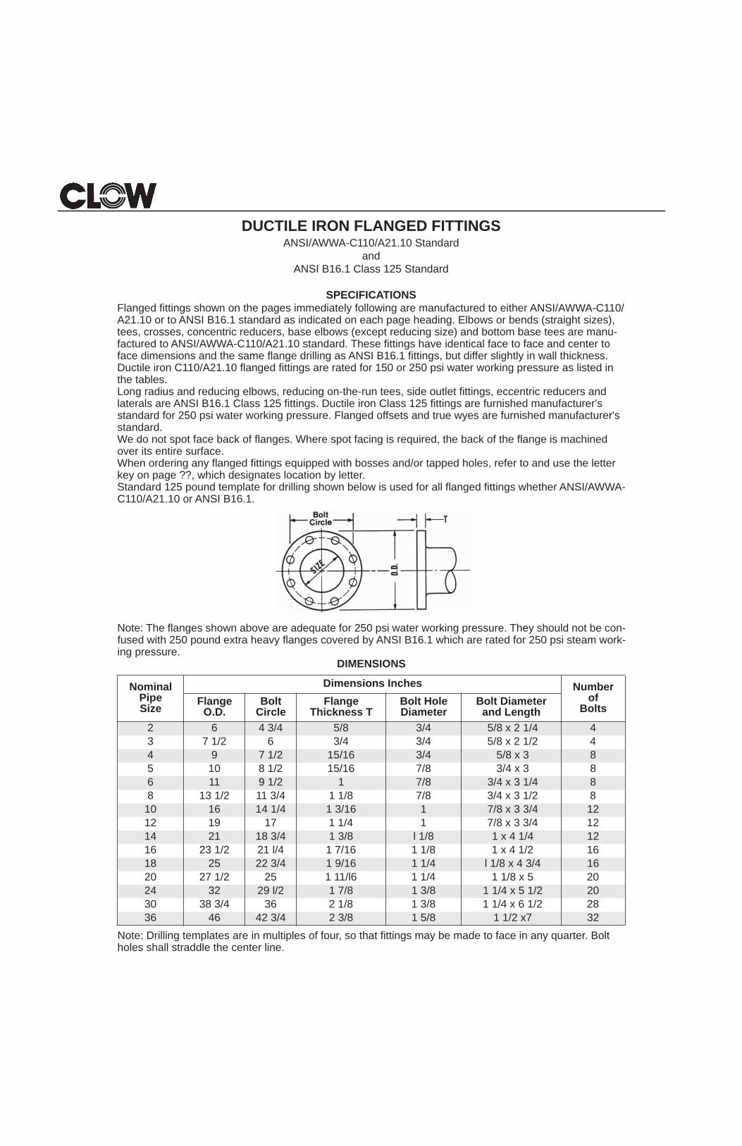
SPECIFICATIONSFlanged fittings shown on the pages immediately following are manufactured to either ANSI/AWWA-C110/A21.10 or to ANSI B16.1 standard as indicated on each page heading. Elbows or bends (straight sizes), tees, crosses, concentric reducers, base elbows (except reducing size) and bottom base tees are manu-factured to ANSI/AWWA-C110/A21.10 standard. These fittings have identical face to face and center to face dimensions and the same flange drilling as ANSI B16.1 fittings, but differ slightly in wall thickness. Ductile iron C110/A21.10 flanged fittings are rated for 150 or 250 psi water working pressure as listed in the tables.Long radius and reducing elbows, reducing on-the-run tees, side outlet fittings, eccentric reducers and laterals are ANSI B16.1 Class 125 fittings. Ductile iron Class 125 fittings are furnished manufacturer's standard for 250 psi water working pressure. Flanged offsets and true wyes are furnished manufacturer's standard.We do not spot face back of flanges. Where spot facing is required, the back of the flange is machined over its entire surface.When ordering any flanged fittings equipped with bosses and/or tapped holes, refer to and use the letter key on page ??, which designates location by letter.Standard 125 pound template for drilling shown below is used for all flanged fittings whether ANSI/AWWA-C110/A21.10 or ANSI B16.1.
Note: The flanges shown above are adequate for 250 psi water working pressure. They should not be con-fused with 250 pound extra heavy flanges covered by ANSI B16.1 which are rated for 250 psi steam work-ing pressure.
DIMENSIONS
Note: Drilling templates are in multiples of four, so that fittings may be made to face in any quarter. Bolt holes shall straddle the center line.
NominalPipeSize
Dimensions Inches Numberof
BoltsFlange O.D.
Bolt Circle
Flange Thickness T
Bolt Hole Diameter
Bolt Diameterand Length
2 6 4 3/4 5/8 3/4 5/8 x 2 1/4 43 7 1/2 6 3/4 3/4 5/8 x 2 1/2 44 9 7 1/2 15/16 3/4 5/8 x 3 85 10 8 1/2 15/16 7/8 3/4 x 3 86 11 9 1/2 1 7/8 3/4 x 3 1/4 88 13 1/2 11 3/4 1 1/8 7/8 3/4 x 3 1/2 810 16 14 1/4 1 3/16 1 7/8 x 3 3/4 1212 19 17 1 1/4 1 7/8 x 3 3/4 1214 21 18 3/4 1 3/8 l 1/8 1 x 4 1/4 1216 23 1/2 21 l/4 1 7/16 1 1/8 1 x 4 1/2 1618 25 22 3/4 1 9/16 1 1/4 l 1/8 x 4 3/4 1620 27 1/2 25 1 11/l6 1 1/4 1 1/8 x 5 2024 32 29 l/2 1 7/8 1 3/8 1 1/4 x 5 1/2 2030 38 3/4 36 2 1/8 1 3/8 1 1/4 x 6 1/2 2836 46 42 3/4 2 3/8 1 5/8 1 1/2 x7 32
53
REDUCING DUCTILE IRON FLANGED FITTINGSHOW TO ORDER
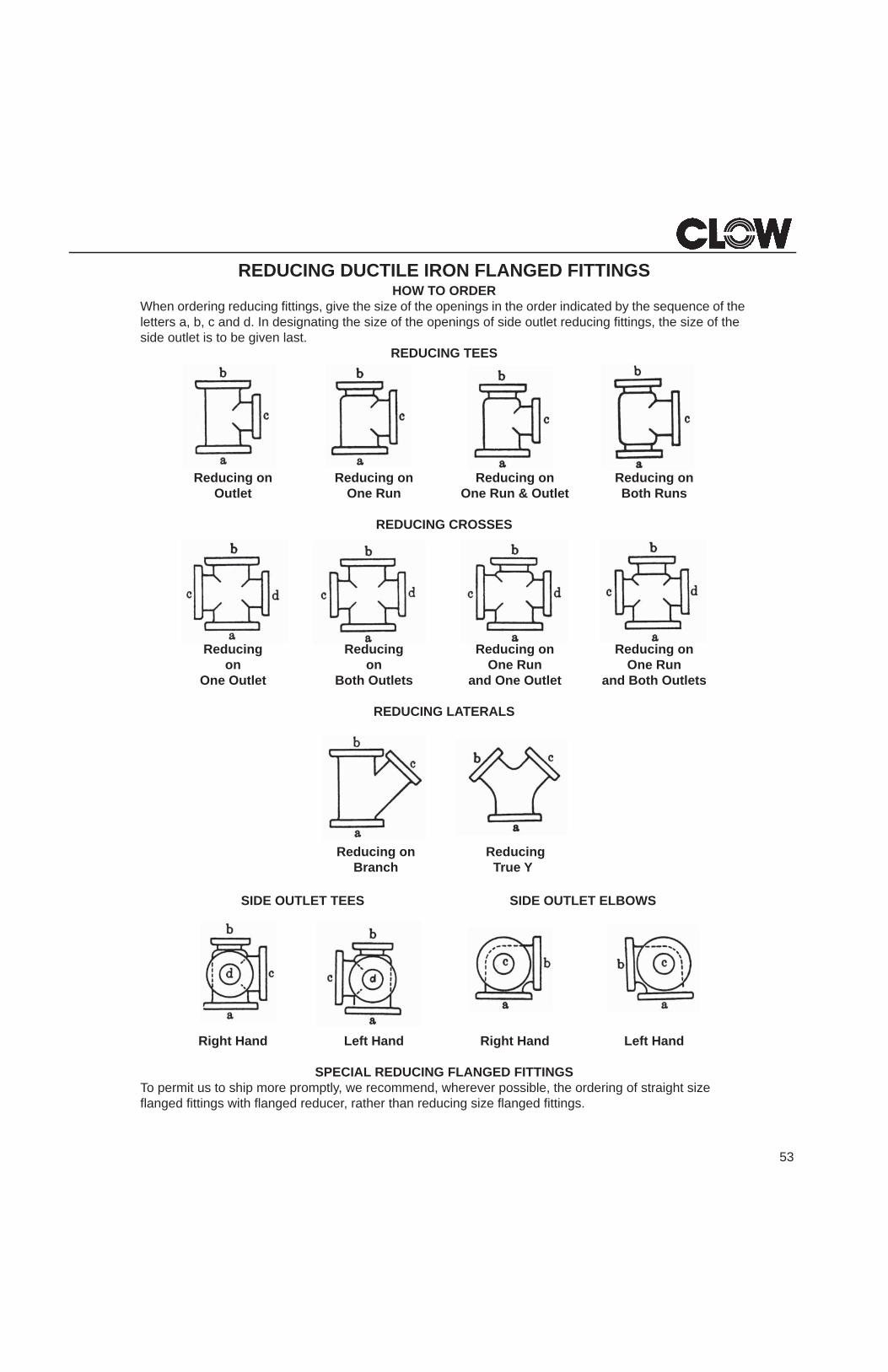
When ordering reducing fittings, give the size of the openings in the order indicated by the sequence of the letters a, b, c and d. In designating the size of the openings of side outlet reducing fittings, the size of the side outlet is to be given last.
REDUCING TEES
Reducing on Reducing on Reducing on Reducing onOutlet One Run One Run & Outlet Both Runs
REDUCING CROSSES
Reducing Reducing Reducing on Reducing onon on One Run One Run
One Outlet Both Outlets and One Outlet and Both Outlets
REDUCING LATERALS
Reducing onBranch
ReducingTrue Y
SIDE OUTLET TEES SIDE OUTLET ELBOWS
Right Hand Left Hand Right Hand Left Hand
SPECIAL REDUCING FLANGED FITTINGSTo permit us to ship more promptly, we recommend, wherever possible, the ordering of straight size flanged fittings with flanged reducer, rather than reducing size flanged fittings.
METHOD OF DESIGNATING OF TAPPED HOLES AND/OR BOSSES IN DUCTILE IRON FLANGED FITTINGS
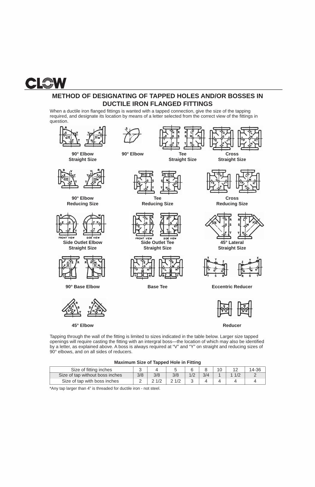
When a ductile iron flanged fittings is wanted with a tapped connection, give the size of the tapping required, and designate its location by means of a letter selected from the correct view of the fittings in question.
90° Elbow 90° Elbow Tee CrosseziS thgiartSeziS thgiartSeziS thgiartS
ssorCeeTwoblE °09Reducing Size Reducing Size Reducing Size
laretaL °54eeT teltuO ediSwoblE teltuO ediSeziS thgiartSeziS thgiartSeziS thgiartS
recudeR cirtneccEeeT esaBwoblE esaB °09
recudeRwoblE °54
Tapping through the wall of the fitting is limited to sizes indicated in the table below. Larger size tapped openings will require casting the fitting with an intergral boss—the location of which may also be identified by a letter, as explained above. A boss is always required at “V” and “Y” on straight and reducing sizes of 90° elbows, and on all sides of reducers.
Maximum Size of Tapped Hole in FittingSize of fitting inches 3 4 5 6 8 10 12 14-36
Size of tap without boss inches 3/8 3/8 3/8 1/2 3/4 1 1 1/2 2Size of tap with boss inches 2 2 1/2 2 1/2 3 4 4 4 4
*Any tap larger than 4” is threaded for ductile iron - not steel.
55
DUCTILE IRON FLANGED FITTINGSANSI/AWWA-C110/A21.10 Standard
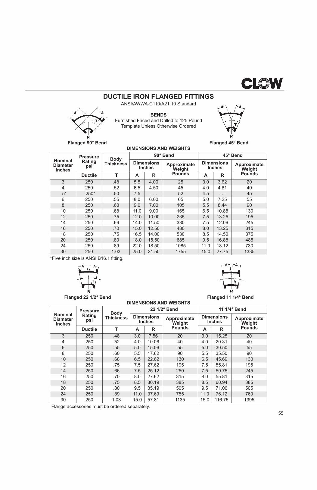
BENDSFurnished Faced and Drilled to 125 Pound
Template Unless Otherwise Ordered
Flanged 90° Bend Flanged 45° BendDIMENSIONS AND WEIGHTS
*Five inch size is ANSI B16.1 fitting.
Flanged 22 1/2° Bend Flanged 11 1/4° BendDIMENSIONS AND WEIGHTS
Flange accessories must be ordered separately.
Nominal Diameter Inches
Pressure Rating
psi
BodyThickness
90° Bend 45° Bend
Dimensions Inches
Approximate WeightPounds
Dimensions Inches
Approximate WeightPoundsDuctile T A R A R
3 250 .48 5.5 4.00 25 3.0 3.62 204 250 .52 6.5 4.50 45 4.0 4.81 40
5* 250* .50 7.5 . . . 52 4.5 . . . 456 250 .55 8.0 6.00 65 5.0 7.25 558 250 .60 9.0 7.00 105 5.5 8.44 9010 250 .68 11.0 9.00 165 6.5 10.88 13012 250 .75 12.0 10.00 235 7.5 13.25 19514 250 .66 14.0 11.50 330 7.5 12.06 24516 250 .70 15.0 12.50 430 8.0 13.25 31518 250 .75 16.5 14.00 530 8.5 14.50 37520 250 .80 18.0 15.50 685 9.5 16.88 48524 250 .89 22.0 18.50 1085 11.0 18.12 73030 250 1.03 25.0 21.50 1755 15.0 27.75 1335
Nominal Diameter Inches
Pressure Rating
psi
Body Thickness
22 1/2° Bend 11 1/4° Bend
DimensionsInches
Approximate Weight Pounds
Dimensions Inches
Approximate WeightPoundsDuctile T A R A R
3 250 .48 3.0 7.56 20 3.0 15.25 204 250 .52 4.0 10.06 40 4.0 20.31 406 250 .55 5.0 15.06 55 5.0 30.50 558 250 .60 5.5 17.62 90 5.5 35.50 90
10 250 .68 6.5 22.62 130 6.5 45.69 13012 250 .75 7.5 27.62 195 7.5 55.81 19514 250 .66 7.5 25.12 250 7.5 50.75 24516 250 .70 8.0 27.62 315 8.0 55.81 31518 250 .75 8.5 30.19 385 8.5 60.94 38520 250 .80 9.5 35.19 505 9.5 71.06 50524 250 .89 11.0 37.69 755 11.0 76.12 76030 250 1.03 15.0 57.81 1135 15.0 116.75 1395
56
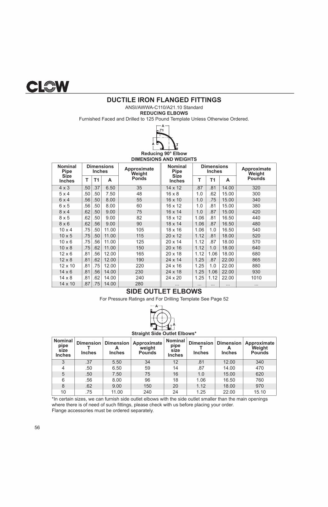
DUCTILE IRON FLANGED FITTINGSANSI/AWWA-C110/A21.10 Standard
REDUCING ELBOWSFurnished Faced and Drilled to 125 Pound Template Unless Otherwise Ordered.
Reducing 90° ElbowDIMENSIONS AND WEIGHTS
SIDE OUTLET ELBOWSFor Pressure Ratings and For Drilling Template See Page 52
Straight Side Outlet Elbows*
*In certain sizes, we can furnish side outlet elbows with the side outlet smaller than the main openings where there is of need of such fittings, please check with us before placing your order.Flange accessories must be ordered separately.
NominalPipeSize
Inches
DimensionsInches Approximate
Weight Ponds
NominalPipeSize
Inches
Dimensions Inches Approximate
Weight PoundsT T1 A T T1 A
4 x 3 .50 .37 6.50 35 14 x 12 .87 .81 14.00 3205 x 4 .50 .50 7.50 48 16 x 8 1.0 .62 15.00 3006 x 4 .56 .50 8.00 55 16 x 10 1.0 .75 15.00 3406 x 5 .56 .50 8.00 60 16 x 12 1.0 .81 15.00 3808 x 4 .62 .50 9.00 75 16 x 14 1.0 .87 15.00 4208 x 5 .62 .50 9.00 82 18 x 12 1.06 .81 16.50 4408 x 6 .62 .56 9.00 90 18 x 14 1.06 .87 16.50 48010 x 4 .75 .50 11.00 105 18 x 16 1.06 1.0 16.50 54010 x 5 .75 .50 11.00 115 20 x 12 1.12 .81 18.00 52010 x 6 .75 .56 11.00 125 20 x 14 1.12 .87 18.00 57010 x 8 .75 .62 11.00 150 20 x 16 1.12 1.0 18.00 64012 x 6 .81 .56 12.00 165 20 x 18 1.12 1.06 18.00 68012 x 8 .81 .62 12.00 190 24 x 14 1.25 .87 22.00 86512 x 10 .81 .75 12.00 220 24 x 16 1.25 1.0 22.00 88014 x 6 .81 .56 14.00 230 24 x 18 1.25 1.06 22.00 93014 x 8 .81 .62 14.00 240 24 x 20 1.25 1.12 22.00 101014 x 10 .87 .75 14.00 280 ... ... ... ... ...
Nominal pipe size
Inches
Dimension T
Inches
Dimension A
Inches
Approximate weight Pounds
Nominal pipe size
Inches
Dimension T
Inches
Dimension A
Inches
Approximate Weight Pounds
3 .37 5.50 34 12 .81 12.00 3404 .50 6.50 59 14 .87 14.00 4705 .50 7.50 75 16 1.0 15.00 6206 .56 8.00 96 18 1.06 16.50 7608 .62 9.00 150 20 1.12 18.00 97010 .75 11.00 240 24 1.25 22.00 15.10
57
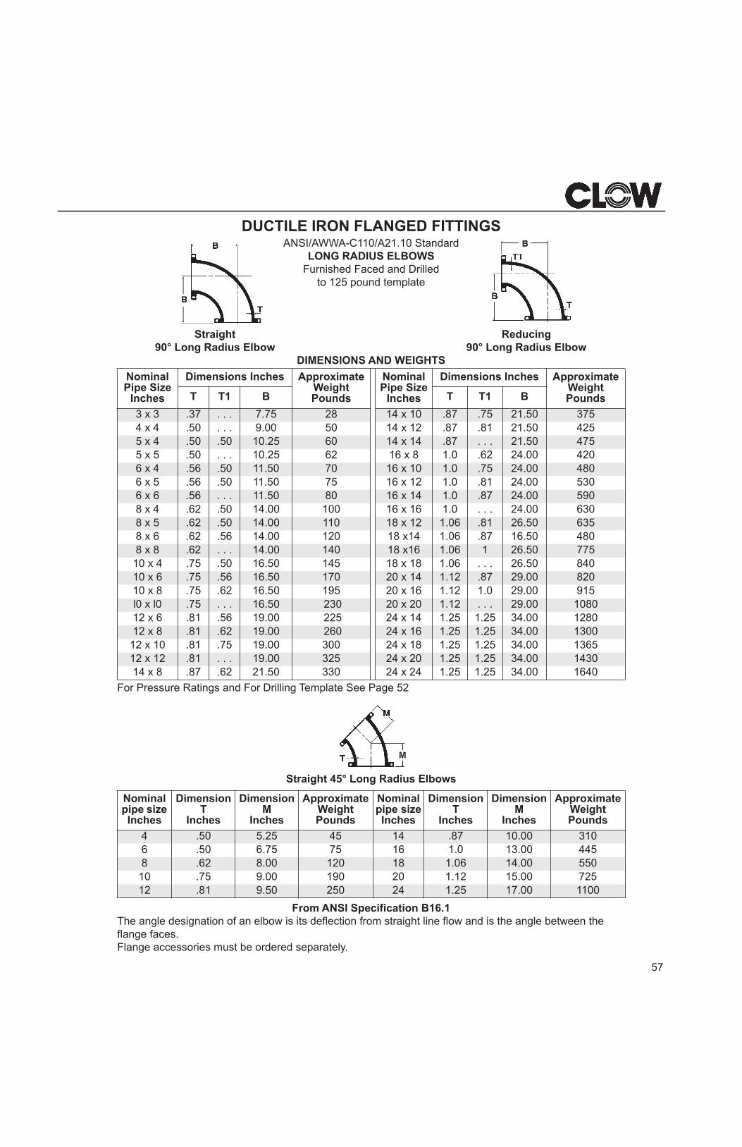
DUCTILE IRON FLANGED FITTINGSANSI/AWWA-C110/A21.10 Standard
LONG RADIUS ELBOWSFurnished Faced and Drilled
to 125 pound template
Straight Reducing90° Long Radius Elbow 90° Long Radius Elbow
DIMENSIONS AND WEIGHTS
For Pressure Ratings and For Drilling Template See Page 52
Straight 45° Long Radius Elbows
From ANSI Specification B16.1The angle designation of an elbow is its deflection from straight line flow and is the angle between the flange faces.Flange accessories must be ordered separately.
Nominal Pipe Size
Inches
Dimensions Inches ApproximateWeightPounds
Nominal Pipe Size
Inches
Dimensions Inches ApproximateWeightPoundsT T1 B T T1 B
3 x 3 .37 . . . 7.75 28 14 x 10 .87 .75 21.50 3754 x 4 .50 . . . 9.00 50 14 x 12 .87 .81 21.50 4255 x 4 .50 .50 10.25 60 14 x 14 .87 . . . 21.50 4755 x 5 .50 . . . 10.25 62 16 x 8 1.0 .62 24.00 4206 x 4 .56 .50 11.50 70 16 x 10 1.0 .75 24.00 4806 x 5 .56 .50 11.50 75 16 x 12 1.0 .81 24.00 5306 x 6 .56 . . . 11.50 80 16 x 14 1.0 .87 24.00 5908 x 4 .62 .50 14.00 100 16 x 16 1.0 . . . 24.00 6308 x 5 .62 .50 14.00 110 18 x 12 1.06 .81 26.50 6358 x 6 .62 .56 14.00 120 18 x14 1.06 .87 16.50 4808 x 8 .62 . . . 14.00 140 18 x16 1.06 1 26.50 775
10 x 4 .75 .50 16.50 145 18 x 18 1.06 . . . 26.50 84010 x 6 .75 .56 16.50 170 20 x 14 1.12 .87 29.00 82010 x 8 .75 .62 16.50 195 20 x 16 1.12 1.0 29.00 915l0 x l0 .75 . . . 16.50 230 20 x 20 1.12 . . . 29.00 108012 x 6 .81 .56 19.00 225 24 x 14 1.25 1.25 34.00 128012 x 8 .81 .62 19.00 260 24 x 16 1.25 1.25 34.00 1300
12 x 10 .81 .75 19.00 300 24 x 18 1.25 1.25 34.00 136512 x 12 .81 . . . 19.00 325 24 x 20 1.25 1.25 34.00 143014 x 8 .87 .62 21.50 330 24 x 24 1.25 1.25 34.00 1640
Nominal pipe size Inches
Dimension T
Inches
Dimension M
Inches
Approximate Weight Pounds
Nominal pipe sizeInches
Dimension T
Inches
Dimension M
Inches
Approximate Weight Pounds
4 .50 5.25 45 14 .87 10.00 3106 .50 6.75 75 16 1.0 13.00 4458 .62 8.00 120 18 1.06 14.00 550
10 .75 9.00 190 20 1.12 15.00 72512 .81 9.50 250 24 1.25 17.00 1100
58
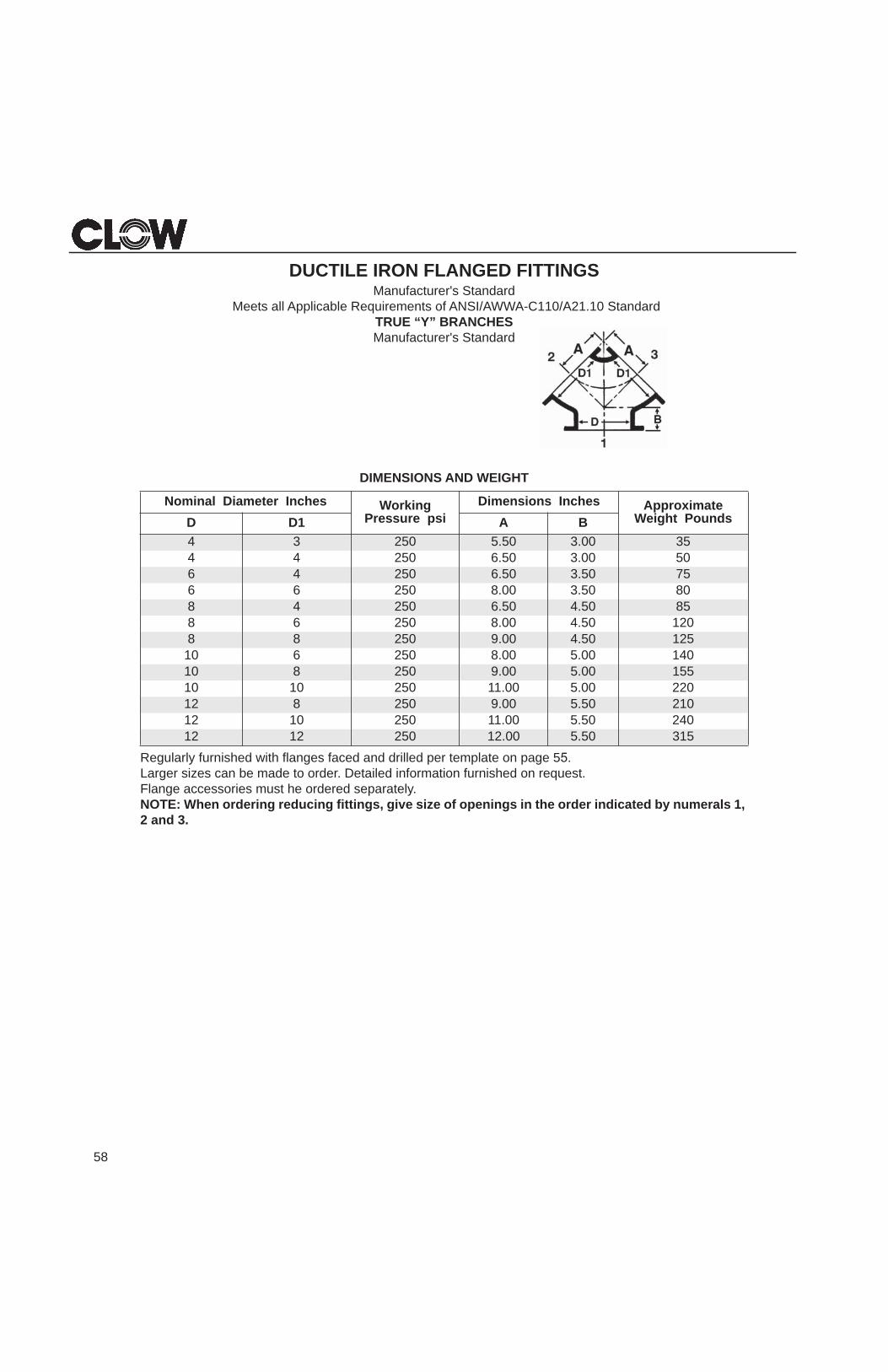
DUCTILE IRON FLANGED FITTINGSManufacturer's Standard
Meets all Applicable Requirements of ANSI/AWWA-C110/A21.10 StandardTRUE “Y” BRANCHESManufacturer's Standard
DIMENSIONS AND WEIGHT
Regularly furnished with flanges faced and drilled per template on page 5 . Larger sizes can be made to order. Detailed information furnished on request. Flange accessories must he ordered separately.NOTE: When ordering reducing fittings, give size of openings in the order indicated by numerals 1, 2 and 3.
Nominal Diameter Inches WorkingPressure psi
Dimensions Inches ApproximateWeight PoundsBA1DD
4 3 250 5.50 3.00 354 4 250 6.50 3.00 506 4 250 6.50 3.50 756 6 250 8.00 3.50 808 4 250 6.50 4.50 858 6 250 8.00 4.50 1208 8 250 9.00 4.50 125
10 6 250 8.00 5.00 14010 8 250 9.00 5.00 15510 10 250 11.00 5.00 22012 8 250 9.00 5.50 21012 10 250 11.00 5.50 24012 12 250 12.00 5.50 315
59
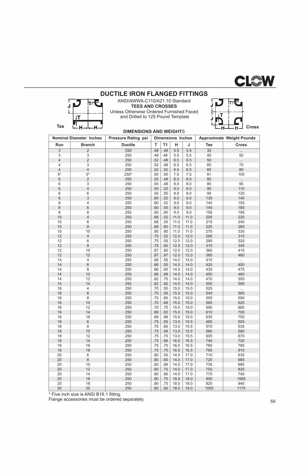
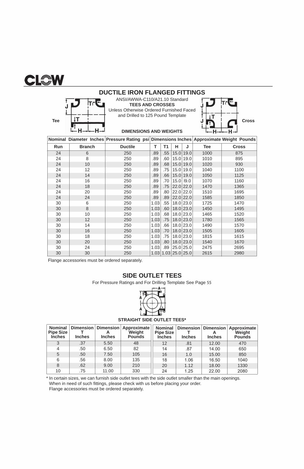
DUCTILE IRON FLANGED FITTINGSANSI/AWWA-C110/A21.10 Standard
TEES AND CROSSESUnless Otherwise Ordered Furnished Faced
and Drilled to 125 Pound Template
DIMENSIONS AND WEIGHTS
* Five inch size is ANSI B16.1 fitting. Flange accessories must be ordered separately.
Nominal Diameter Inches Pressure Rating psi Dimensions Inches Approximate Weight Pounds
Run Branch Ductile T T1 H J Tee Cross
3 2 250 .48 .48 5.5 5.5 35 ...3 3 250 .48 48 5.5 5.5 40 504 2 250 .52 .48 6.5 6.5 50 ...4 3 250 .52 .48 6.5 6.5 60 704 4 250 .52 .52 6.5 6.5 60 805* 5* 250* .50 .50 7.5 7.5 81 1056 2 250 .55 .48 8.0 8.0 85 ...6 3 250 .55 .48 8.0 8.0 85 956 4 250 .55 .52 8.0 8.0 90 1106 6 250 .55 .55 8.0 8.0 95 1208 3 250 .60 .52 9.0 9.0 130 1408 4 250 .60 .52 9.0 9.0 140 1558 6 250 .60 .55 9.0 9.0 145 1658 8 250 .60 .60 9.0 9.0 155 19510 4 250 .68 .52 11.0 11.0 205 22010 6 250 .68 .55 11.0 11.0 215 24010 8 250 .68 .60 11.0 11.0 225 26510 10 250 .80 .80 11.0 11.0 270 33012 4 250 .75 .52 12.0 12.0 290 31012 6 250 .75 .55 12.0 12.0 295 32012 8 250 .75 .60 12.0 12.0 310 34512 10 250 .87 .80 12.0 12.0 360 41512 12 250 .87 .87 12.0 12.0 385 46014 4 250 .66 .55 14.0 14.0 410 ...14 6 250 .66 .55 14.0 14.0 420 45014 8 250 .66 .60 14.0 14.0 435 47514 10 250 .66 .68 14.0 14.0 450 46014 12 250 .82 .75 14.0 14.0 470 55514 14 250 .82 .82 14.0 14.0 500 59516 4 250 .70 .55 15.0 15.0 525 ...16 6 250 .70 .55 15.0 15.0 540 56516 8 250 .70 .60 15.0 15.0 555 59016 10 250 .70 .68 15.0 15.0 565 62016 12 250 .70 .75 15.0 15.0 590 66516 14 250 .89 .82 15.0 15.0 610 70016 16 250 .89 .89 15.0 15.0 635 75518 6 250 .75 .55 13.0 15.5 480 50518 8 250 .75 .60 13.0 15.5 570 53518 10 250 .75 .68 13.0 15.5 580 56018 12 250 .75 .75 13.0 15.5 605 67018 14 250 .75 .66 16.5 16.5 740 72018 16 250 .75 .70 16.5 16.5 760 76518 18 250 .75 .75 16.5 16.5 785 91520 6 250 .80 .55 14.0 17.0 710 63520 8 250 .80 .60 14.0 17.0 720 66520 10 250 .80 .68 14.0 17.0 735 68520 12 250 .80 .75 14.0 17.0 755 82020 14 250 .80 .66 14.0 17.0 770 74520 16 250 .80 .70 18.0 18.0 950 106520 18 250 .80 .75 18.0 18.0 820 94520 20 250 .80 .80 18.0 18.0 1005 1175
CrossTee
DUCTILE IRON FLANGED FITTINGSANSI/AWWA-C110/A21.10 Standard
TEES AND CROSSESUnless Otherwise Ordered Furnished Faced
and Drilled to 125 Pound TemplateTee Cross
DIMENSIONS AND WEIGHTS
Flange accessories must be ordered separately.
SIDE OUTLET TEESFor Pressure Ratings and For Drilling Template See Page 55
STRAIGHT SIDE OUTLET TEES*
* In certain sizes, we can furnish side outlet tees with the side outlet smaller than the main openings.When in need of such fittings, please check with us before placing your order.Flange accessories must be ordered separately.
Nominal Diameter Inches Pressure Rating psi Dimensions Inches Approximate Weight PoundsRun Branch Ductile T T1 H J Tee Cross24 6 250 .89 .55 15.0 19.0 1000 87524 8 250 .89 .60 15.0 19.0 1010 89524 10 250 .89 .68 15.0 19.0 1020 93024 12 250 .89 .75 15.0 19.0 1040 110024 14 250 .89 .66 15.0 19.0 1050 112524 16 250 .89 .70 15.0 l9.0 1070 116024 18 250 .89 .75 22.0 22.0 1470 136524 20 250 .89 .80 22.0 22.0 1510 169524 24 250 .89 .89 22.0 22.0 1585 185030 6 250 1.03 .55 18.0 23.0 1725 147030 8 250 1.03 .60 18.0 23.0 1450 149530 10 250 1.03 .68 18.0 23.0 1465 152030 12 250 1.03 .75 18.0 23.0 1780 156530 14 250 1.03 .66 18.0 23.0 1490 157030 16 250 1.03 .70 18.0 23.0 1505 160530 18 250 1.03 .75 18.0 23.0 1815 161530 20 250 1.03 .80 18.0 23.0 1540 167030 24 250 1.03 .89 25.0 25.0 2475 269530 30 250 1.03 1.03 25.0 25.0 2615 2980
Nominal Pipe Size
Inches
Dimension T
Inches
Dimension A
Inches
Approximate Weight Pounds
3 .37 5.50 484 .50 6.50 825 .50 7.50 1056 .56 8.00 1358 .62 9.00 210
10 .75 11.00 330
Nominal Pipe Size
Inches
Dimension T
Inches
Dimension A
Inches
Approximate Weight Pounds
12 .81 12.00 470
16 1.0 15.00 850
20 1.12 18.00 1330
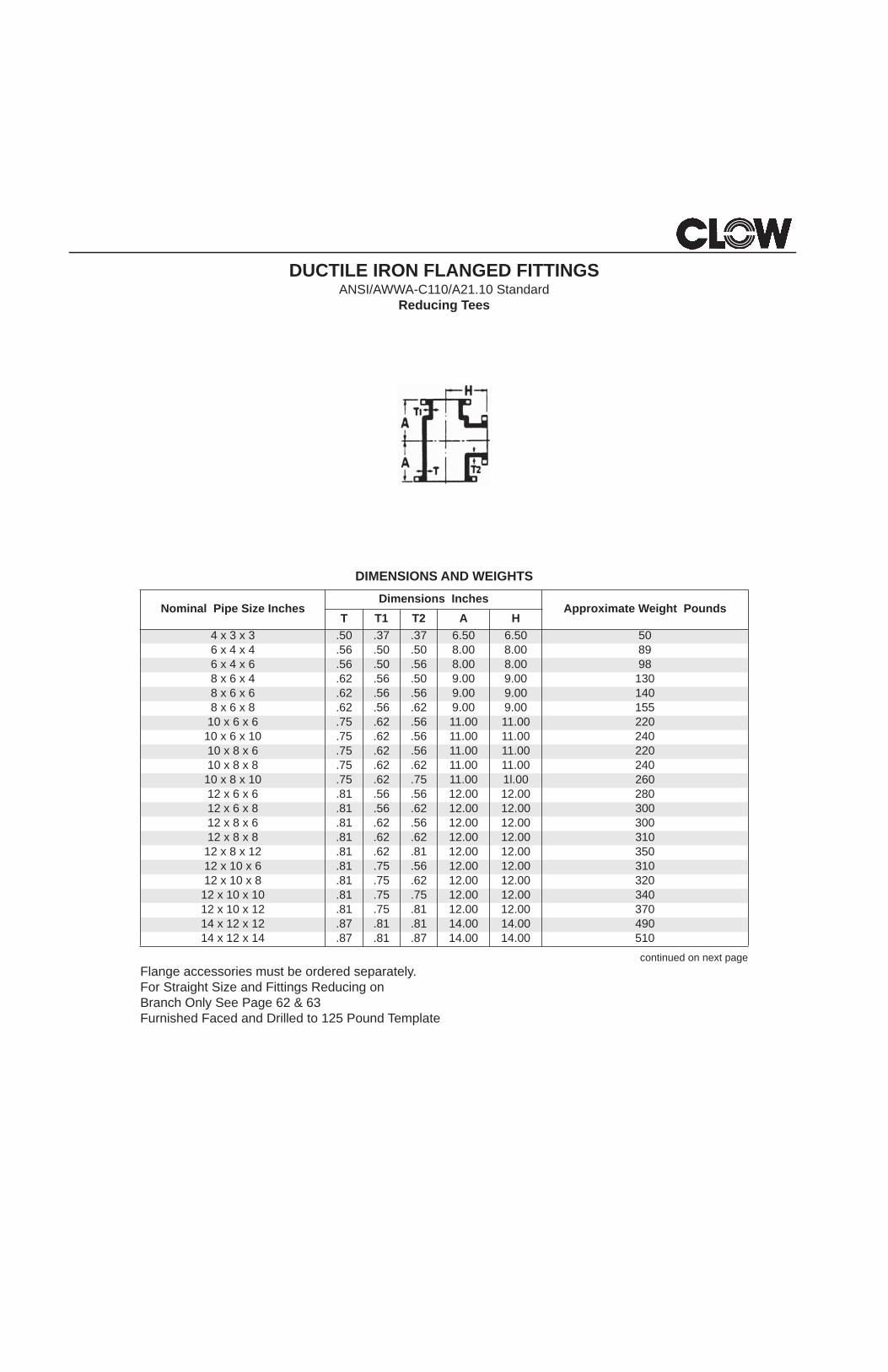
DUCTILE IRON FLANGED FITTINGSANSI/AWWA-C110/A21.10 Standard
Reducing Tees
DIMENSIONS AND WEIGHTS
continued on next pageFlange accessories must be ordered separately.For Straight Size and Fittings Reducing on Branch Only See Page 62 & 63Furnished Faced and Drilled to 125 Pound Template
Nominal Pipe Size InchesDimensions Inches
Approximate Weight PoundsT T1 T2 A H
4 x 3 x 3 .50 .37 .37 6.50 6.50 506 x 4 x 4 .56 .50 .50 8.00 8.00 896 x 4 x 6 .56 .50 .56 8.00 8.00 988 x 6 x 4 .62 .56 .50 9.00 9.00 1308 x 6 x 6 .62 .56 .56 9.00 9.00 1408 x 6 x 8 .62 .56 .62 9.00 9.00 15510 x 6 x 6 .75 .62 .56 11.00 11.00 220
10 x 6 x 10 .75 .62 .56 11.00 11.00 24010 x 8 x 6 .75 .62 .56 11.00 11.00 22010 x 8 x 8 .75 .62 .62 11.00 11.00 24010 x 8 x 10 .75 .62 .75 11.00 1l.00 26012 x 6 x 6 .81 .56 .56 12.00 12.00 28012 x 6 x 8 .81 .56 .62 12.00 12.00 30012 x 8 x 6 .81 .62 .56 12.00 12.00 30012 x 8 x 8 .81 .62 .62 12.00 12.00 310
12 x 8 x 12 .81 .62 .81 12.00 12.00 35012 x 10 x 6 .81 .75 .56 12.00 12.00 31012 x 10 x 8 .81 .75 .62 12.00 12.00 32012 x 10 x 10 .81 .75 .75 12.00 12.00 34012 x 10 x 12 .81 .75 .81 12.00 12.00 37014 x 12 x 12 .87 .81 .81 14.00 14.00 49014 x 12 x 14 .87 .81 .87 14.00 14.00 510
62
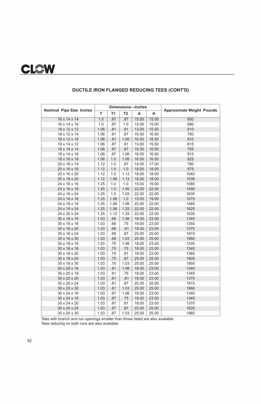
DUCTILE IRON FLANGED REDUCING TEES (CONT'D)
Tees with branch and run openings smaller than those listed are also available.Tees reducing on both runs are also available.
Nominal Pipe Size InchesDimensions—Inches
Approximate Weight PoundsT T1 T2 A H
16 x 14 x 14 1.0 .87 .87 15.00 15.00 65016 x 14 x 16 1.0 .87 1.0 15.00 15.00 68018 x 12 x 12 1.06 .81 .81 13.00 15.50 61018 x 12 x 14 1.06 .81 .87 16.50 16.50 75018 x 12 x 18 1.06 .81 1.06 16.50 16.50 81018 x 14 x 12 1.06 .87 .81 13.00 15.50 61518 x 14 x 14 1.06 .87 .87 16.50 16.50 75518 x 14 x 18 1.06 .87 1.06 16.50 16.50 81518 x 16 x 18 1.06 1.0 1.06 16.50 16.50 82520 x 16 x 14 1.12 1.0 .87 14.00 17.00 78020 x 16 x 16 1.12 1.0 1.0 18.00 18.00 97520 x 16 x 20 1.12 1.0 1.12 18.00 18.00 104020 x 18 x 20 1.12 1.06 1.12 18.00 18.00 103024 x 16 x 16 1.25 1.0 1.0 15.00 19.00 108524 x 16 x 18 1.25 1.0 1.06 22.00 22.00 149524 x 16 x 24 1.25 1.0 1.25 22.00 22.00 163524 x 18 x 16 1.25 1.06 1.0 15.00 19.00 107024 x 18 x 18 1.25 1.06 1.06 22.00 22.00 148524 x 18 x 24 1.25 1.06 1.25 22.00 22.00 162524 x 20 x 24 1.25 1.12 1.25 22.00 22.00 163030 x 16 x 16 1.03 .68 1.06 18.00 23.00 134530 x 16 x 18 1.03 .68 .75 18.00 23.00 135030 x 16 x 20 1.03 .68 .81 18.00 23.00 137530 x 16 x 24 1.03 .68 .87 25.00 25.00 181530 x 16 x 30 1.03 .68 1.03 25.00 25.00 196030 x 18 x 16 1.03 .75 1.06 18.00 23.00 133530 x 18 x 18 1.03 .75 .75 18.00 23.00 134030 x 18 x 20 1.03 .75 .81 18.00 23.00 136530 x 18 x 24 1.03 .75 .87 25.00 25.00 180530 x 18 x 30 1.03 .75 1.03 25.00 25.00 195530 x 20 x 16 1.03 .81 1.06 18.00 23.00 134030 x 20 x 18 1.03 .81 .75 18.00 23.00 134530 x 20 x 20 1.03 .81 .81 18.00 23.00 137030 x 20 x 24 1.03 .81 .87 25.00 25.00 181530 x 20 x 30 1.03 .81 1.03 25.00 25.00 196030 x 24 x 16 1.03 .87 1.06 18.00 23.00 134030 x 24 x 18 1.03 .87 .75 18.00 23.00 134530 x 24 x 20 1.03 .87 .81 18.00 23.00 137030 x 24 x 24 1.03 .87 .87 25.00 25.00 182030 x 24 x 30 1.03 .87 1.03 25.00 25.00 1965
63
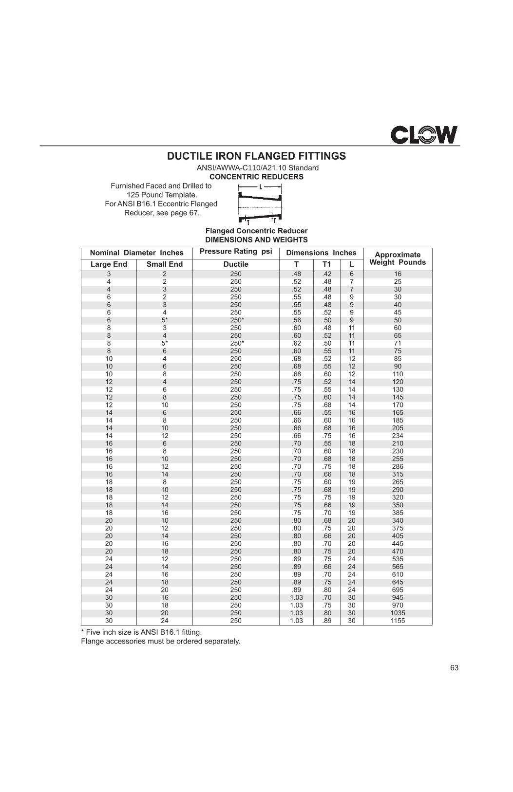
DUCTILE IRON FLANGED FITTINGSANSI/AWWA-C110/A21.10 Standard
CONCENTRIC REDUCERSFurnished Faced and Drilled to
125 Pound Template.For ANSI B16.1 Eccentric Flanged
Reducer, see page 67.
Flanged Concentric ReducerDIMENSIONS AND WEIGHTS
* Five inch size is ANSI B16.1 fitting.Flange accessories must be ordered separately.
Nominal Diameter Inches Pressure Rating psi Dimensions Inches ApproximateWeight PoundsLarge End Small End Ductile T T1 L
3 2 250 .48 .42 6 164 2 250 .52 .48 7 254 3 250 .52 .48 7 306 2 250 .55 .48 9 306 3 250 .55 .48 9 406 4 250 .55 .52 9 456 5* 250* .56 .50 9 508 3 250 .60 .48 11 608 4 250 .60 .52 11 658 5* 250* .62 .50 11 718 6 250 .60 .55 11 7510 4 250 .68 .52 12 8510 6 250 .68 .55 12 9010 8 250 .68 .60 12 11012 4 250 .75 .52 14 12012 6 250 .75 .55 14 13012 8 250 .75 .60 14 14512 10 250 .75 .68 14 17014 6 250 .66 .55 16 16514 8 250 .66 .60 16 18514 10 250 .66 .68 16 20514 12 250 .66 .75 16 23416 6 250 .70 .55 18 21016 8 250 .70 .60 18 23016 10 250 .70 .68 18 25516 12 250 .70 .75 18 28616 14 250 .70 .66 18 31518 8 250 .75 .60 19 26518 10 250 .75 .68 19 29018 12 250 .75 .75 19 32018 14 250 .75 .66 19 35018 16 250 .75 .70 19 38520 10 250 .80 .68 20 34020 12 250 .80 .75 20 37520 14 250 .80 .66 20 40520 16 250 .80 .70 20 44520 18 250 .80 .75 20 47024 12 250 .89 .75 24 53524 14 250 .89 .66 24 56524 16 250 .89 .70 24 61024 18 250 .89 .75 24 64524 20 250 .89 .80 24 69530 16 250 1.03 .70 30 94530 18 250 1.03 .75 30 97030 20 250 1.03 .80 30 103530 24 250 1.03 .89 30 1155
64
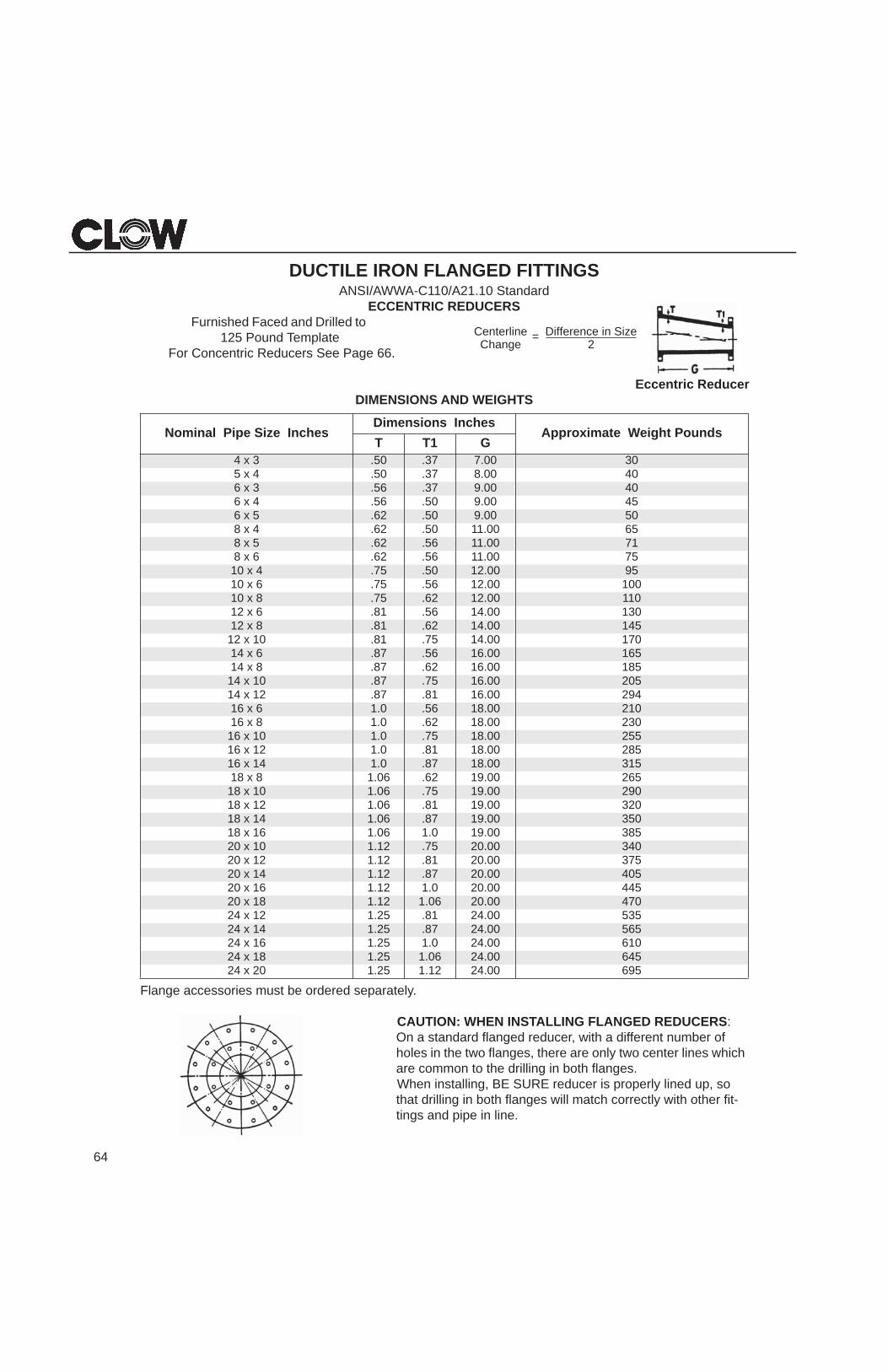
DUCTILE IRON FLANGED FITTINGSANSI/AWWA-C110/A21.10 Standard
ECCENTRIC REDUCERSFurnished Faced and Drilled to
125 Pound TemplateFor Concentric Reducers See Page 66.
Eccentric ReducerDIMENSIONS AND WEIGHTS
Flange accessories must be ordered separately.
CAUTION: WHEN INSTALLING FLANGED REDUCERS: On a standard flanged reducer, with a different number of holes in the two flanges, there are only two center lines which are common to the drilling in both flanges.When installing, BE SURE reducer is properly lined up, so that drilling in both flanges will match correctly with other fit-tings and pipe in line.
Nominal Pipe Size InchesDimensions Inches
Approximate Weight PoundsT T1 G
4 x 3 .50 .37 7.00 300400.873.05.4 x 5
6 x 3 .56 .37 9.00 405400.905.65.4 x 6
6 x 5 .62 .50 9.00 505600.1105.26.4 x 8
8 x 5 .62 .56 11.00 715700.1165.26.6 x 8
10 x 4 .75 .50 12.00 9500100.2165.57.6 x 01
10 x 8 .75 .62 12.00 11003100.4165.18.6 x 21
12 x 8 .81 .62 14.00 14507100.4157.18.01 x 21
14 x 6 .87 .56 16.00 16558100.6126.78.8 x 41
14 x 10 .87 .75 16.00 20549200.6118.78.21 x 41
16 x 6 1.0 .56 18.00 21003200.8126.0.18 x 61
16 x 10 1.0 .75 18.00 25558200.8118.0.121 x 61
16 x 14 1.0 .87 18.00 31556200.9126.60.18 x 81
18 x 10 1.06 .75 19.00 29002300.9118.60.121 x 81
18 x 14 1.06 .87 19.00 35058300.910.160.161 x 81
20 x 10 1.12 .75 20.00 34057300.0218.21.121 x 02
20 x 14 1.12 .87 20.00 40554400.020.121.161 x 02
20 x 18 1.12 1.06 20.00 47053500.4218.52.121 x 42
24 x 14 1.25 .87 24.00 56501600.420.152.161 x 42
24 x 18 1.25 1.06 24.00 64559600.4221.152.102 x 42
CenterlineChange
= Difference in Size2
65
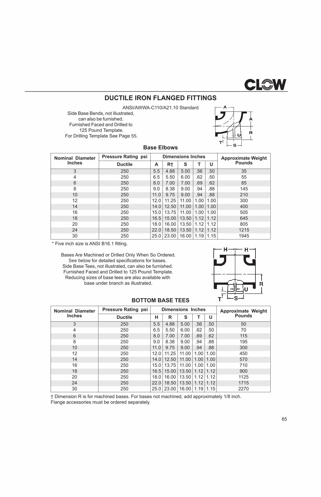
DUCTILE IRON FLANGED FITTINGSANSI/AWWA-C110/A21.10 Standard
Side Base Bends, not illustrated, can also be furnished.
Furnished Faced and Drilled to 125 Pound Template.
For Drilling Template See Page 55.
Base Elbows
* Five inch size is ANSI B16.1 fitting.
Bases Are Machined or Drilled Only When So Ordered. See below for detailed specifications for bases.
Side Base Tees, not illustrated, can also be furnished. Furnished Faced and Drilled to 125 Pound Template.Reducing sizes of base tees are also available with
base under branch as illustrated.
BOTTOM BASE TEES
† Dimension R is for machined bases. For bases not machined, add approximately 1/8 inch.Flange accessories must be ordered separately.
Nominal Diameter Inches
Pressure Rating psi Dimensions Inches Approximate Weight PoundsDuctile A R† S T U
3 250 5.5 4.88 5.00 .56 .50 354 250 6.5 5.50 6.00 .62 .50 556 250 8.0 7.00 7.00 .69 .62 858 250 9.0 8.38 9.00 .94 .88 14510 250 11.0 9.75 9.00 .94 .88 21012 250 12.0 11.25 11.00 1.00 1.00 30014 250 14.0 12.50 11.00 1.00 1.00 40016 250 15.0 13.75 11.00 1.00 1.00 50518 250 16.5 15.00 13.50 1.12 1.12 64520 250 18.0 16.00 13.50 1.12 1.12 80524 250 22.0 18.50 13.50 1.12 1.12 121530 250 25.0 23.00 16.00 1.19 1.15 1945
Nominal Diameter Inches
Pressure Rating psi Dimensions Inches Approximate Weight PoundsDuctile H R S T U
3 250 5.5 4.88 5.00 .56 .50 504 250 6.5 5.50 6.00 .62 .50 706 250 8.0 7.00 7.00 .69 .62 1158 250 9.0 8.38 9.00 .94 .88 195
10 250 11.0 9.75 9.00 .94 .88 30012 250 12.0 11.25 11.00 1.00 1.00 45014 250 14.0 12.50 11.00 1.00 1.00 57016 250 15.0 13.75 11.00 1.00 1.00 71018 250 16.5 15.00 13.50 1.12 1.12 90020 250 18.0 16.00 13.50 1.12 1.12 112524 250 22.0 18.50 13.50 1.12 1.12 171530 250 25.0 23.00 16.00 1.19 1.15 2270
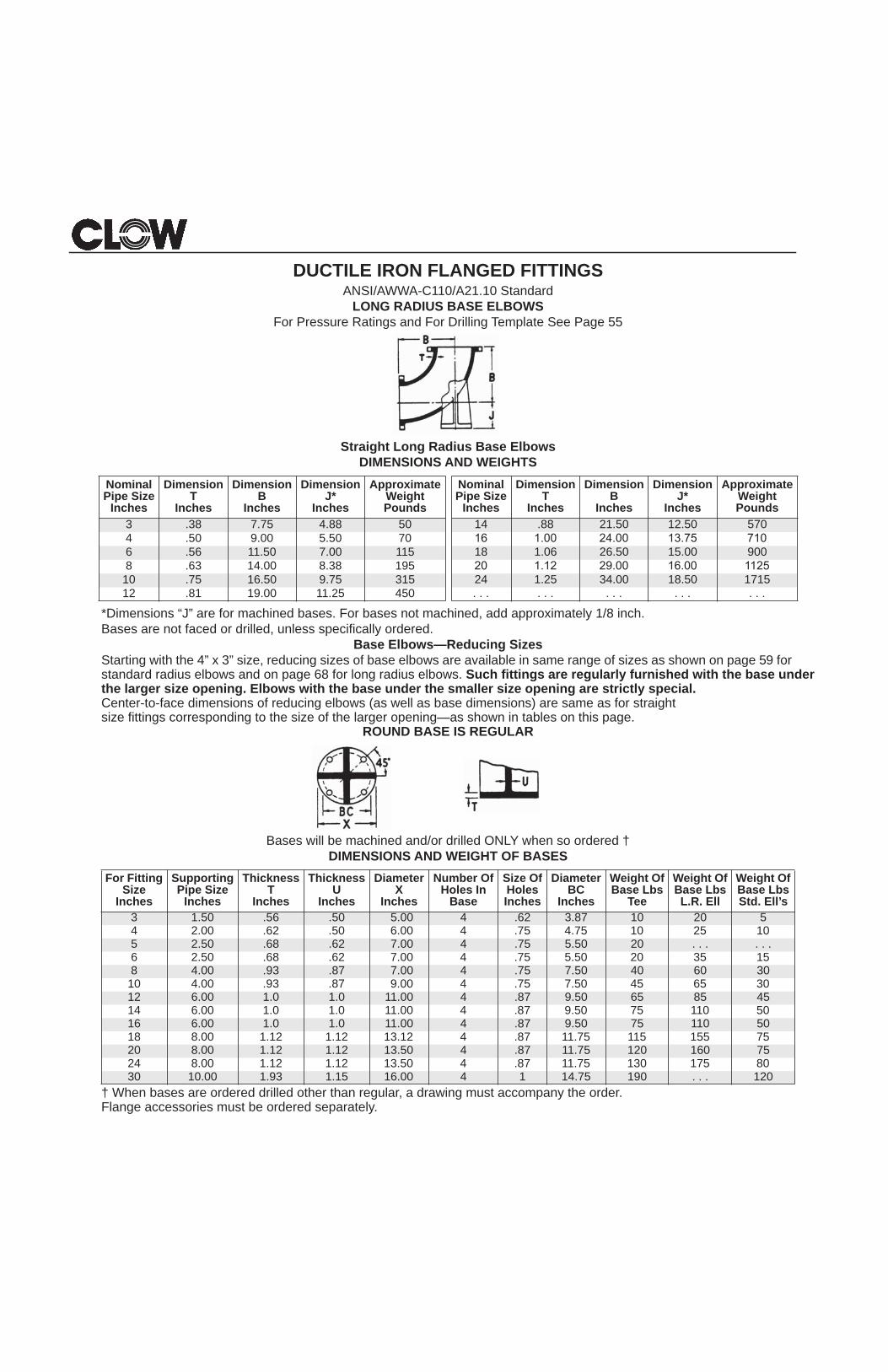
DUCTILE IRON FLANGED FITTINGSANSI/AWWA-C110/A21.10 Standard
LONG RADIUS BASE ELBOWSFor Pressure Ratings and For Drilling Template See Page 55
Straight Long Radius Base ElbowsDIMENSIONS AND WEIGHTS
*Dimensions “J” are for machined bases. For bases not machined, add approximately 1/8 inch.Bases are not faced or drilled, unless specifically ordered.
Base Elbows—Reducing SizesStarting with the 4” x 3” size, reducing sizes of base elbows are available in same range of sizes as shown on page 59 for standard radius elbows and on page 68 for long radius elbows. Such fittings are regularly furnished with the base under the larger size opening. Elbows with the base under the smaller size opening are strictly special.Center-to-face dimensions of reducing elbows (as well as base dimensions) are same as for straightsize fittings corresponding to the size of the larger opening—as shown in tables on this page.
ROUND BASE IS REGULAR
Bases will be machined and/or drilled ONLY when so ordered †DIMENSIONS AND WEIGHT OF BASES
† When bases are ordered drilled other than regular, a drawing must accompany the order. Flange accessories must be ordered separately.
Nominal Pipe Size
Inches
Dimension T
Inches
Dimension B
Inches
Dimension J*
Inches
Approximate Weight Pounds
3 .38 7.75 4.88 504 .50 9.00 5.50 706 .56 11.50 7.00 1158 .63 14.00 8.38 19510 .75 16.50 9.75 31512 .81 19.00 11.25 450
For Fitting Size
Inches
Supporting Pipe Size
Inches
Thickness T
Inches
Thickness U
Inches
Diameter X
Inches
Number Of Holes In
Base
Size Of Holes Inches
Diameter BC
Inches
Weight Of Base Lbs
Tee
Weight Of Base LbsL.R. Ell
Weight Of Base LbsStd. Ell’s
3 1.50 .56 .50 5.00 4 .62 3.87 10 20 54 2.00 .62 .50 6.00 4 .75 4.75 10 25 105 2.50 .68 .62 7.00 4 .75 5.50 20 . . . . . .6 2.50 .68 .62 7.00 4 .75 5.50 20 35 158 4.00 .93 .87 7.00 4 .75 7.50 40 60 30
10 4.00 .93 .87 9.00 4 .75 7.50 45 65 3012 6.00 1.0 1.0 11.00 4 .87 9.50 65 85 4514 6.00 1.0 1.0 11.00 4 .87 9.50 75 110 5016 6.00 1.0 1.0 11.00 4 .87 9.50 75 110 5018 8.00 1.12 1.12 13.12 4 .87 11.75 115 155 7520 8.00 1.12 1.12 13.50 4 .87 11.75 120 160 7524 8.00 1.12 1.12 13.50 4 .87 11.75 130 175 8030 10.00 1.93 1.15 16.00 4 1 14.75 190 . . . 120
Nominal Pipe Size
Inches
Dimension T
Inches
Dimension B
Inches
Dimension J*
Inches
Approximate Weight Pounds
14 .88 21.50 12.50 570
18 1.06 26.50 15.00 900
24 1.25 34.00 18.50 1715
67
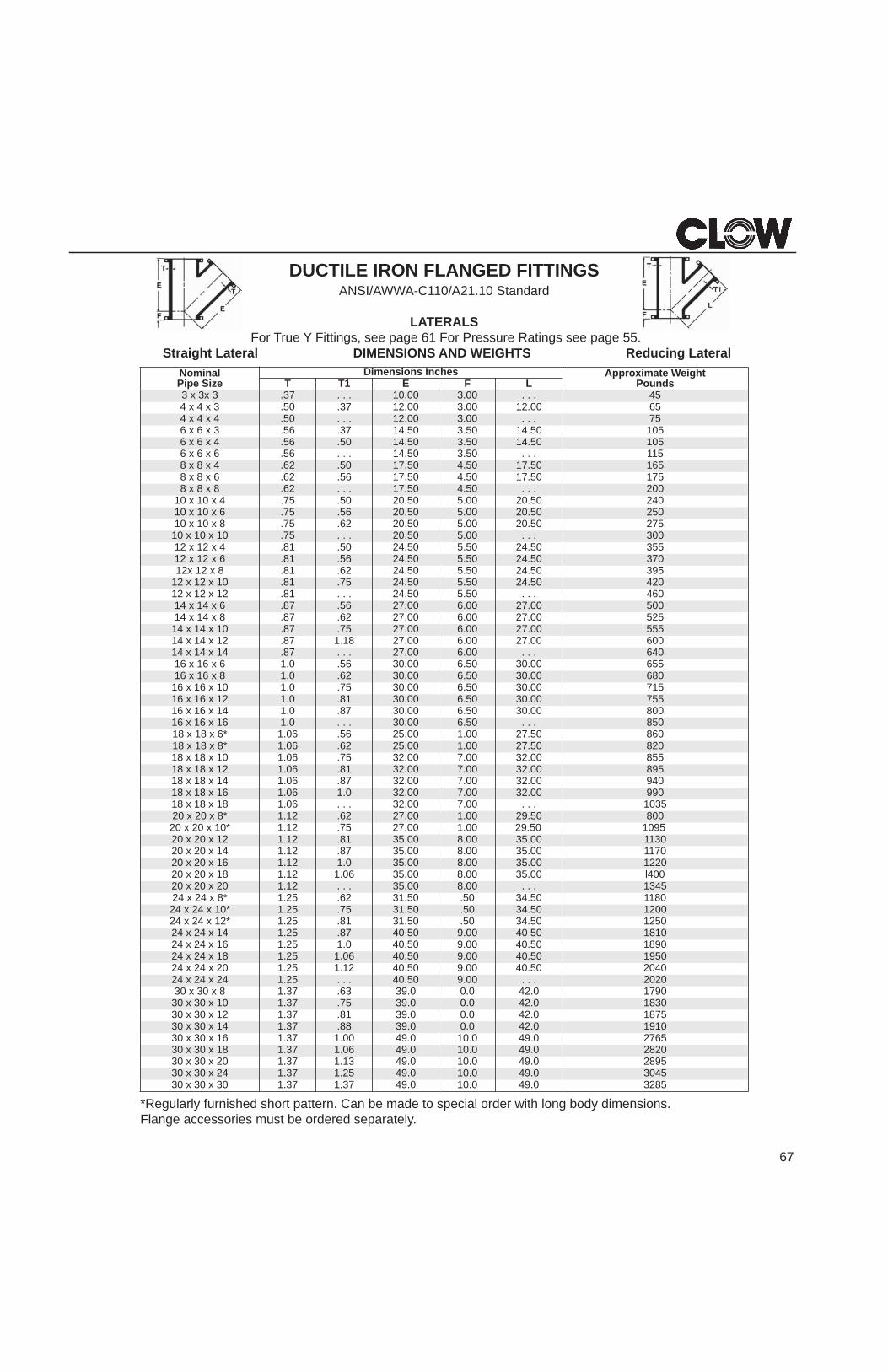
DUCTILE IRON FLANGED FITTINGSANSI/AWWA-C110/A21.10 Standard
LATERALSFor True Y Fittings, see page 61 For Pressure Ratings see page 55.
Straight Lateral DIMENSIONS AND WEIGHTS Reducing Lateral
*Regularly furnished short pattern. Can be made to special order with long body dimensions. Flange accessories must be ordered separately.
Nominal Pipe Size
Dimensions Inches Approximate Weight PoundsT T1 E F L
3 x 3x 3 .37 . . . 10.00 3.00 . . . 455600.2100.300.2173.05.3 x 4 x 4
4 x 4 x 4 .50 . . . 12.00 3.00 . . . 7550105.4105.305.4173.65.3 x 6 x 6
6 x 6 x 4 .56 .50 14.50 3.50 14.50 105511. . .05.305.41. . .65.6 x 6 x 6
8 x 8 x 4 .62 .50 17.50 4.50 17.50 16557105.7105.405.7165.26.6 x 8 x 8
8 x 8 x 8 .62 . . . 17.50 4.50 . . . 20004205.0200.505.0205.57.4 x 01 x 01
10 x 10 x 6 .75 .56 20.50 5.00 20.50 25057205.0200.505.0226.57.8 x 01 x 01
10 x 10 x 10 .75 . . . 20.50 5.00 . . . 30055305.4205.505.4205.18.4 x 21 x 21
12 x 12 x 6 .81 .56 24.50 5.50 24.50 37059305.4205.505.4226.18.8 x 21 x21
12 x 12 x 10 .81 .75 24.50 5.50 24.50 420064. . .05.505.42. . .18.21 x 21 x 21
14 x 14 x 6 .87 .56 27.00 6.00 27.00 50052500.7200.600.7226.78.8 x 41 x 41
14 x 14 x 10 .87 .75 27.00 6.00 27.00 55500600.7200.600.7281.178.21 x 41 x 41
14 x 14 x 14 .87 . . . 27.00 6.00 . . . 64055600.0305.600.0365.0.16 x 61 x 61
16 x 16 x 8 1.0 .62 30.00 6.50 30.00 68051700.0305.600.0357.0.101 x 61 x 61
16 x 16 x 12 1.0 .81 30.00 6.50 30.00 75500800.0305.600.0378.0.141 x 61 x 61
16 x 16 x 16 1.0 . . . 30.00 6.50 . . . 85006805.7200.100.5265.60.1*6 x 81 x 81
18 x 18 x 8* 1.06 .62 25.00 1.00 27.50 82055800.2300.700.2357.60.101 x 81 x 81
18 x 18 x 12 1.06 .81 32.00 7.00 32.00 89504900.2300.700.2378.60.141 x 81 x 81
18 x 18 x 16 1.06 1.0 32.00 7.00 32.00 9905301. . .00.700.23. . .60.181 x 81 x 81
20 x 20 x 8* 1.12 .62 27.00 1.00 29.50 80020 x 20 x 10* 1.12 .75 27.00 1.00 29.50 109520 x 20 x 12 1.12 .81 35.00 8.00 35.00 113020 x 20 x 14 1.12 .87 35.00 8.00 35.00 117020 x 20 x 16 1.12 1.0 35.00 8.00 35.00 122020 x 20 x 18 1.12 1.06 35.00 8.00 35.00 l40020 x 20 x 20 1.12 . . . 35.00 8.00 . . . 134524 x 24 x 8* 1.25 .62 31.50 .50 34.50 118024 x 24 x 10* 1.25 .75 31.50 .50 34.50 120024 x 24 x 12* 1.25 .81 31.50 .50 34.50 125024 x 24 x 14 1.25 .87 40 50 9.00 40 50 181024 x 24 x 16 1.25 1.0 40.50 9.00 40.50 189024 x 24 x 18 1.25 1.06 40.50 9.00 40.50 195024 x 24 x 20 1.25 1.12 40.50 9.00 40.50 204024 x 24 x 24 1.25 . . . 40.50 9.00 . . . 2020
09710.240.00.9336.73.18 x 03 x 0330 x 30 x 10 1.37 .75 39.0 0.0 42.0 1830
57810.240.00.9318.73.121 x 03 x 0330 x 30 x 14 1.37 .88 39.0 0.0 42.0 1910
56720.940.010.9400.173.161 x 03 x 0330 x 30 x 18 1.37 1.06 49.0 10.0 49.0 2820
59820.940.010.9431.173.102 x 03 x 0330 x 30 x 24 1.37 1.25 49.0 10.0 49.0 3045
58230.940.010.9473.173.103 x 03 x 03
68
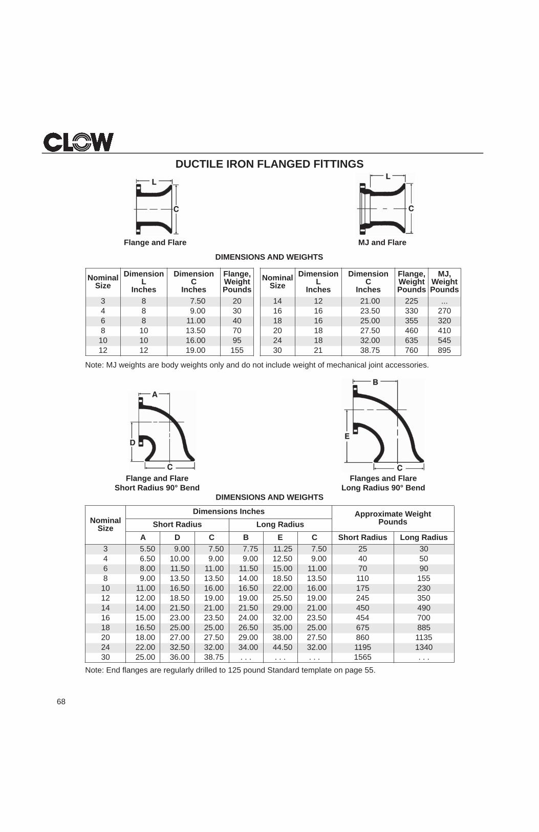
DUCTILE IRON FLANGED FlTTINGS
Flange and Flare MJ and Flare
Note: MJ weights are body weights only and do not include weight of mechanical joint accessories.
Flange and Flare Flanges and FlareShort Radius 90° Bend Long Radius 90° Bend
DIMENSIONS AND WEIGHTS
Note: End flanges are regularly drilled to 125 pound Standard template on page 55.
NominalSize
Dimensions Inches Approximate Weight PoundsShort Radius Long Radius
A D C B E C Short Radius Long Radius3 5.50 9.00 7.50 7.75 11.25 7.50 25 304 6.50 10.00 9.00 9.00 12.50 9.00 40 506 8.00 11.50 11.00 11.50 15.00 11.00 70 908 9.00 13.50 13.50 14.00 18.50 13.50 110 155
10 11.00 16.50 16.00 16.50 22.00 16.00 175 23012 12.00 18.50 19.00 19.00 25.50 19.00 245 35014 14.00 21.50 21.00 21.50 29.00 21.00 450 49016 15.00 23.00 23.50 24.00 32.00 23.50 454 70018 16.50 25.00 25.00 26.50 35.00 25.00 675 88520 18.00 27.00 27.50 29.00 38.00 27.50 860 113524 22.00 32.50 32.00 34.00 44.50 32.00 1195 134030 25.00 36.00 38.75 . . . . . . . . . 1565 . . .
DIMENSIONS AND WEIGHTS
NominalSize
Dimension L
Inches
Dimension C
Inches
Flange, Weight Pounds
MJ, Weight Pounds
14 12 21.00 225 ...16 16 23.50 330 27018 16 25.00 355 32020 18 27.50 460 41024 18 32.00 635 54530 21 38.75 760 895
NominalSize
Dimension L
Inches
Dimension C
Inches
Flange, Weight Pounds
3 8 7.50 204 8 9.00 306 8 11.00 408 10 13.50 70
10 10 16.00 9512 12 19.00 155
70
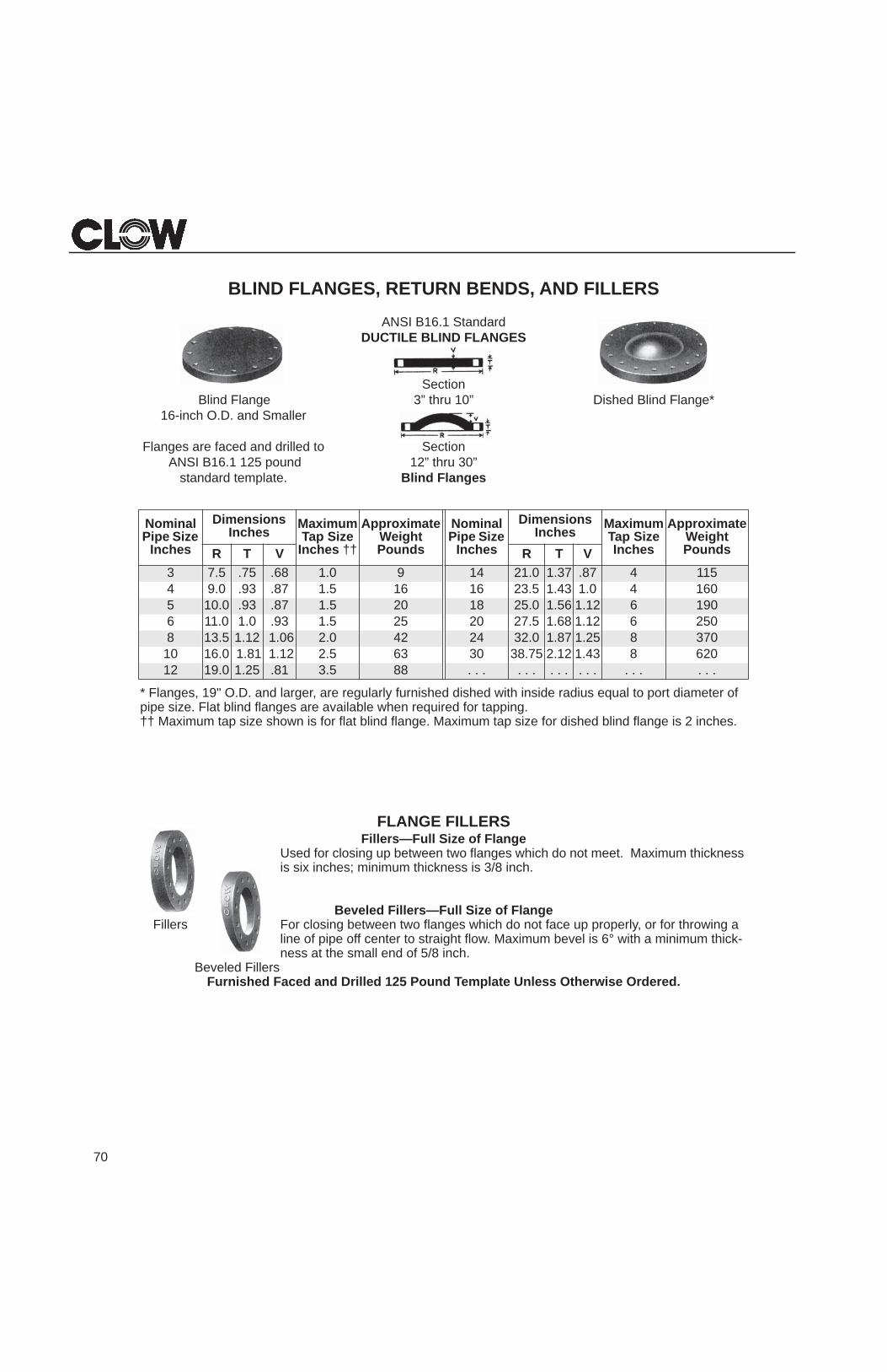
BLIND FLANGES, RETURN BENDS, AND FILLERS
ANSI B16.1 StandardDUCTILE BLIND FLANGES
Section*egnalF dnilB dehsiD”01 urht ”3egnalF dnilB
16-inch O.D. and Smaller 19-lnch O.D. and Larger
Flanges are faced and drilled to Section ANSI B16.1 125 pound 12” thru 30”
standard template. Blind Flanges
* Flanges, 19" O.D. and larger, are regularly furnished dished with inside radius equal to port diameter of pipe size. Flat blind flanges are available when required for tapping. †† Maximum tap size shown is for flat blind flange. Maximum tap size for dished blind flange is 2 inches.
FLANGE FILLERSFillers—Full Size of Flange
Used for closing up between two flanges which do not meet. Maximum thickness is six inches; minimum thickness is 3/8 inch.
Beveled Fillers—Full Size of FlangeFillers For closing between two flanges which do not face up properly, or for throwing a
line of pipe off center to straight flow. Maximum bevel is 6° with a minimum thick-ness at the small end of 5/8 inch.
Beveled FillersFurnished Faced and Drilled 125 Pound Template Unless Otherwise Ordered.
Nominal Pipe Size
Inches
Dimensions Inches Maximum
Tap Size Inches ††
ApproximateWeight Pounds
Nominal Pipe Size
Inches
Dimensions Inches Maximum
Tap Size Inches
ApproximateWeight PoundsR T V R T V
3 7.5 .75 .68 1.0 9 14 21.0 1.37 .87 4 1154 9.0 .93 .87 1.5 16 16 23.5 1.43 1.0 4 1605 10.0 .93 .87 1.5 20 18 25.0 1.56 1.12 6 1906 11.0 1.0 .93 1.5 25 20 27.5 1.68 1.12 6 2508 13.5 1.12 1.06 2.0 42 24 32.0 1.87 1.25 8 370
10 16.0 1.81 1.12 2.5 63 30 38.75 2.12 1.43 8 62012 19.0 1.25 .81 3.5 88 . . . . . . . . . . . . . . . . . .
71
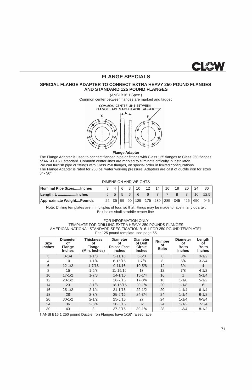
FLANGE SPECIALSSPECIAL FLANGE ADAPTER TO CONNECT EXTRA HEAVY 250 POUND FLANGES
AND STANDARD 125 POUND FLANGES(ANSI B16.1 Spec.)
Common center between flanges are marked and tagged
Flange AdapterThe Flange Adapter is used to connect flanged pipe or fittings with Class 125 flanges to Class 250 flanges of ANSI B16.1 standard. Common center lines are marked to eliminate difficulty in installaton.We can furnish pipe or fittings with Class 250 flanges, on special order in limited configurations.The Flange Adapter is rated for 250 psi water working pressure. Adapters are cast of ductile iron for sizes 3” - 30”.
DIMENSION AND WEIGHTS
Note: Drilling templates are in multiples of four, so that fittings may be made to face in any quarter.Bolt holes shall straddle center line.
FOR INFORMATION ONLYTEMPLATE FOR DRILLING EXTRA HEAVY 250 POUNDS FLANGES
AMERICAN NATIONAL STANDARD SPECIFICATION B16.1 FOR 250 POUND TEMPLATE†For 125 pound template, see page 55.
† ANSI B16.1 250 pound Ductile Iron Flanges have 1/16" raised face.
Nominal Pipe Sizes......Inches 3 4 6 8 10 12 14 16 18 20 24 30Length, L ..................Inches 5 5 5 6 6 6 7 7 8 8 10 12.5Approximate Weight....Pounds 25 35 55 90 125 175 230 285 345 425 650 945
Size Inches
Diameterof
FlangeInches
Thicknessof
Flange(Min. Inches)
Diameterof
Raised FaceInches
Diameterof BoltCircleInches
Numberof
Bolts
Diameterof
BoltsInches
Lengthof
BoltsInches
3 8-1/4 1-1/8 5-11/16 6-5/8 8 3/4 3-1/24 10 1-1/4 6-15/16 7-7/8 8 3/4 3-3/46 12-1/2 1-7/16 9-11/16 10-5/8 12 3/4 48 15 1-5/8 11-15/16 13 12 7/8 4-1/2
10 17-1/2 1-7/8 14-1/16 15-1/4 16 1 5-1/412 20-1/2 2 16-7/16 17-3/4 16 1-1/8 5-1/214 23 2-1/8 18-15/16 20-1/4 20 1-1/8 616 25-1/2 2-1/4 21-1/16 22-1/2 20 1-1/4 6-1/418 28 2-3/8 25-5/16 24-3/4 24 1-1/4 6-1/220 30-1/2 2-1/2 25-5/16 27 24 1-1/4 6-3/424 36 2-3/4 30-5/16 32 24 1-1/2 7-3/430 43 3 37-3/16 39-1/4 28 1-3/4 8-1/2

72
DUCTILE IRON FLANGED FITTINGSANSI/AWWA-C110/A21.10 Standard
SLUDGE SHOESClow sludge shoes are extra strong, have maximum sludge opening,
and the flare reduces entrance loss to a minimum.SUCTION STRAINERS
The aggregate area of perforations is greater than the pipe area.
Flanged End* Flanged End*Sludge Shoe Suction Strainer
Sludge Shoe
Suction Strainer
Slots in all strainers are 1/2 inch wide.*Note: Flanged ends are regularly furnished faced and drilled to 125 pound template—see page 55.
DUCTILE IRON OVERFLOW RINGSFor establishing any desired overflow water-line in tanks. Support pipe, counterbored for Overflow Ring, required for installation.
Specify length *when orderingSection
Minimum Laying Length is One Inch
Pipe Size Inches
Dimensions InchesApproximate Weight
PoundsLaid Height
Diameter at Base
Diameter of Flare
Floor to Bottom of the Flare
3 12.00 5.75 ... 6.00 254 12.00 8.00 8.75 6.00 406 13.00 10.00 11.00 7.00 608 14.00 12.50 13.50 8.00 85
10 15.00 14.50 15.50 8.00 12012 15.00 17.00 18.00 8.00 150
Pipe Size Inches
O.D. of Strainer Inches
Area in Square Inches Overall Length “L” in Inches
Approximate WeightPoundsof Pipe Port of Perforations
4 7.00 12.50 20.00 11.75 406 9.00 28.00 37.50 12.25 758 13.00 50.00 75.00 15.00 115
10 15.25 78.50 84.00 20.63 17512 17.25 113.00 126.00 22.13 260
Nominal Pipe Size Inches
Outside Diameter Inches
Inside Diameter Inches
Weight, Per Inch Of Laying Length Pounds
6 6.90 5.86 2.68 9.05 7.91 3.9
10 11.10 9.92 5.212 13.20 11.92 6.714 15.30 13.92 8.216 17.40 15.94 9.9