duct heaters
TRANSCRIPT

LISTED• CUSTOM BUILT TO ORDER
• STOCK MODELS• STANDARD RIBBED OR HIGH PERFORMANCE
ARROWHEAD CERAMIC INSULATORSMODEL SERIES: DH

CONTENTSPage No.
Warranty 2
Introduction 3
Rush Program 3
Available Models 3
Construction Features 4
Models DHR and DHA 5
Model DRP 6
Construction Components 7
Control Components 8
Dimensional Data 12
Wiring Diagrams 13
Engineering – Heater Selection 16
Duct Heater Location 19
Duct Heater Installation 20
NEC and UL Code Requirements 29
Submittal Form 30
Heater Configurations 31
Suggested Specifications back cover
ELECTRIC DUCT HEATERS by Nailor Industries Inc.
2
WARRANTYNailor Industries Inc. standard warranty extends only to the first purchaser of each new Electric DuctHeater. Nailor Industries Inc. guarantees that its products and components when installed correctly andin accordance with the manufacturer's installation instructions and when properly maintained, will be freefrom defects in workmanship and materials for one year after installation, but not to exceed 18 monthsafter manufacture.
If a product or a component is found not to comply with this warranty, the duct heater shall be returnedwith a Return Material Authorization number freight pre-paid to the factory for examination. If failure isdue to causes other than faulty installation or abuse, Nailor Industries Inc. will solely at their own option,repair or replace components parts found to be defective at no charge and return to the buyer withshipping charges pre-paid.
Nailor Industries Inc. will not be obligated in any way for any charges or costs in connection with trouble-shooting, removal, re-installation or return transportation of heaters or for any direct or indirect damages,loss of profits or incidental or consequential damages, howsoever caused.
Extended Warranty: Nailor Industries Inc. will offer an extended warranty of three years from ship datefor all duct heaters so specified in the original engineering specification with 'Arrowhead' type insulators.
This extended warranty is also optionally available when requested on any and all duct heaterspurchased with 'Arrowhead' type insulators regardless of original engineering design specification.Contact your Nailor Industries Inc. representative for further details.
Catalog No. DH June, 1999. Printed in Canada.
Copyright © 1999 by Nailor Industries Inc. All rights reserved. No part of this catalog may be reproduced or transmitted in any form or by any means, electronic ormechanical, including photocopying and recording, or by any information storage and retrieval system without permission in writing from Nailor Industries Inc.
Nailor Industries Inc. pursues a policy of continuous product development and we therefore reserve the right to change any of the information in this publication withoutnotice. Contact your Nailor Industries Inc. representative to verify current product details.
Nailor Industries Inc. Electric DuctHeaters have been tested andapproved to the following standards byETL Testing Laboratories Inc.,Courtland, N.Y.(Listing Report No. 554250. Category:Duct Heaters 327 U.S.A. and 328Canada)
ANSI/UL Standard 1996, 1st ed.
CSA Standard C22.2 No. 155-M1986.
cLISTEDLISTED
INTRODUCTIONNailor Electric Duct Heaters are self-contained heatingunits designed for installation in air handling systems.Some heaters are an integral part of other equipment,some have been approved for direct attachment to otherequipment such as heat pumps, fans and variable airvolume terminals, while others are approved for use ascomplete heating units to be mounted in air ducts.
Nailor Electric Duct Heaters provide precision heating forproper space control by handling dynamic heating loaddemands. Multiple locations within a single building allowsmaximum potential for individual control of each zone.
Nailor Electric Duct Heaters can be used as primary heat,preheat, reheat and supplemental heat or auxiliary heat.
Primary heat is the heat source for the entire building.
Preheat is used to temper air where it enters the buildingand prior to another air conditioning source.
Reheat is used to raise the air temperature of air previouslyconditioned by another process before distribution to thezone.
Supplemental or auxiliary heat is used to temporarilyboost the heating capacity of another piece of equipmentsuch as a heat pump.
Nailor Electric Duct Heaters are designed with electricalresistance elements arranged in the most advantageouspattern for heat transfer to the air stream. Nailor DuctHeaters provide constant heat as long as the heater isenergized and the air velocity over the elements isconstant. The wire surface temperature may vary from800°F to 1200°F (427°C to 649°C) under normalconditions so that the operating temperature is belowthat which would produce a red glow.
Nailor Electric Duct Heaters are available with open coil,helically wound resistance heating elements exposeddirectly to the air stream. The elements are supportedby ceramic insulators, either ribbed type that surroundthe element, or arrowhead type that leave the elementcompletely exposed to the air stream. Open coilelements offer little resistance to airflow and provide avery small surface to attract dirt or lint.
RUSH PROGRAMWhen time is at a premium and you need rapid delivery,Nailor can be relied upon to solve your problem.
Either choose from one of the select range of "Nailorstock" models or alternatively take advantage of one ofthe Nailor express shipping programs for custom "builtto order" duct heaters:
One week shipment (5 working days)
48 hour shipment (2 working days)
Consult your local Nailor representative for furtherinformation.
TWO BASIC CONFIGURATIONSSlip-in / Insert Type (standard):Slip-in type heaters are constructed to slide the entire frame,excluding the terminal box, into an opening in one side of aduct without removing or disturbing the duct section.
Flanged Type (optional):Flanged heaters are constructed with flanges on theheater frame. They become a section of the duct wheninstalled. The inside dimensions of the frame match theinside dimensions of the duct.
THE NAILOR MODELSModel DHR:The basic ETL listed slip-in model with all controls in anenclosed panel attached to the heater. The element wireis encapsulated in ribbed ceramics. Model DHR isavailable in custom sizes and all kW ranges. All controlsand accessories can be used with the model DHR.
Model DHA:Same as the Model DHR except with arrowhead insulatorsthat leave the entire element wire exposed to the airstream. Model DHA is ETL listed and available incustom sizes and all kW ranges. All controls andaccessories can be used with the model DHA.
Models DRR & DRA :The same as Models DHR and DHA respectively, exceptarranged for remote panels. These units must be sold andshipped with the ETL listed Model DRP Remote Panel.
Model DRP:An ETL listed Remote Panel Assembly for use with one ofthe heaters (Model DRR or DRA) by Nailor. The panelassembly can be wall or floor mounted. All controls for theheater are housed in this panel with the exception of thehigh temperature limit switches and the airflow switch.
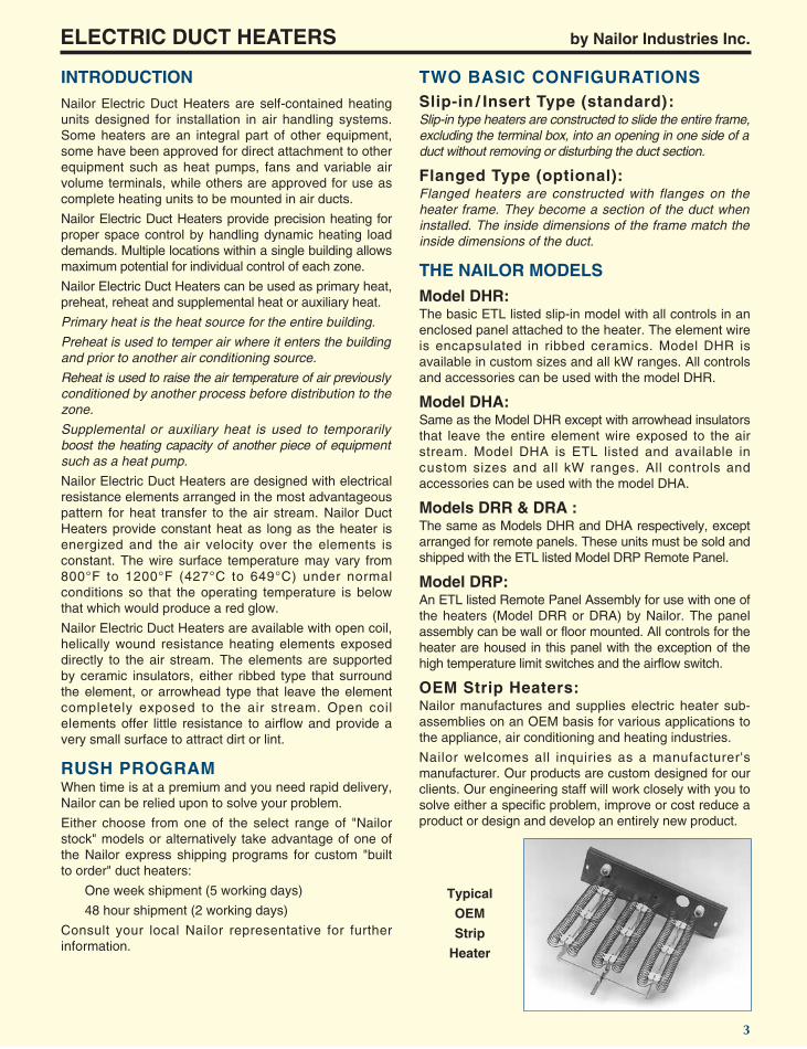
OEM Strip Heaters:Nailor manufactures and supplies electric heater sub-assemblies on an OEM basis for various applications tothe appliance, air conditioning and heating industries.
Nailor welcomes all inquiries as a manufacturer'smanufacturer. Our products are custom designed for ourclients. Our engineering staff will work closely with you tosolve either a specific problem, improve or cost reduce aproduct or design and develop an entirely new product.
ELECTRIC DUCT HEATERS by Nailor Industries Inc.
3
Typical
OEM
Strip
Heater

Magnetic contactor is built-in.
(See contactors,magnetic, page 6;mercury, page 9).
ELECTRIC DUCT HEATERS by Nailor Industries Inc.
4
Fuses are provided as standardequipment on all heaters exceeding48 amps. The total load will be equallydivided into circuits of no more than48 amps each. Each circuit will befused at a maximum of 60 amps.Fuses are optional on all otherheaters.
Fuses are required on non-Class 2transformers. Class 2 transformersdo not require fuses.
CONSTRUCTION FEATURES
Nailor manufactures every element wire for each applicationfrom highest grade nickel/chromium wire for longer life andelimination of coil sag and oxidation. Conservative ratingassures low operating temperatures, and coils do not glow ifthere is adequate airflow across the entire face.
Ribbed type insulators with ceramic bushings featuresupport brackets that are specially reinforced along theedges. Holes are upset for extra strength.
Arrowhead type insulators (shown) optimize heat transfer.
Coil terminations are designed to providetrouble-free connections. Corrosion-resistant terminals and ceramic bushingsresist high temperatures. Coil connectionis mechanically crimped and nuts aretightened to specific torque. (See page 7).
• Corrosion-resistant terminal
• Resistance coil mechanically crimped to terminal
Solid, non-perforated box cover protectsbuilt-in contactors from dust; assurestrouble-free operation. Screws areaccessible from front. Cover is hinged.
Main power supply terminal blocks are
provided as standardfor field connection.
Differentialpressure airflow switch
providespositive protection
against loss of airflow.
Terminal box is heavy gauge,corrosion-resistant steel.(Galvanized is standard).
Power knock-outs areproperly sized for
conduit connection.
Every Nailor Electric Duct Heater iscomplete with both primary andsecondary over-temperature protection. An automatic resetting open disk hightemperature limit will open the controlcircuit on the entire heater if an over-temperature condition exists. In case offailure, a secondary set of manuallyresetting or replaceable high temperaturelimits are wired in series with eachelement wire. These are set for highertemperatures than the automatic deviceto preclude nuisance tripping. A sufficientnumber of secondary limits are availableto de-energize the heater in case ofprimary failure. All limits may be servicedthrough the control box. No back-upcontactors are required. (See page 7).
• High temperature ceramic bushings
Primary auto-reset
Secondary manual reset

Model DHR – Ribbed Insulators
MODELS DHR AND DHABasic Custom Heater Models
.1 to 1000 kW
UL STANDARD 1996 AND NECREQUIREMENTSHeaters with current loads over 48 amperes must besubdivided into multiple circuits, each of which must notexceed 48 amperes. Each sub-circuit must be internallyfused or supplied with other overcurrent devices (circuitbreakers) furnished by the heater manufacturer.
Heaters must be provided with a grounding terminal or lug.
Heaters must be furnished by the manufacturer with anairflow switch (pressure type) or with fan interlock relaysin the heater control panel.
Heaters must be furnished with an individual and specificwiring diagram permanently fixed to the control panel ofthe heater.
Heaters must be furnished with proper safety and warninglabels to warn of electric shock hazard.
Heaters must be furnished by the manufacturer withinstallation instructions.
ELECTRICAL OPTIONS:kW Range .1 to 1000Power Voltage: 120 to 600 VACPhase: Single or ThreeControl Voltage: 24, 120, 208, 240 or 277 VAC
ACCESSORIES:1. Air Pressure Switch2. Fan Interlock Relay3. Manual Reset Limits4. Insulation on Panel5. Control Transformer (Class 2)6. Control Transformer (Fused per NEC)7. Circuit Fusing per NEC8. Circuit Fusing in excess of NEC requirements9. Circuit Breakers10. Disconnect Switch (Toggle Type)11. Disconnect Switch (Door Interlocking)12. Quiet Contactors13. Mercury Contactors14. P.E. Switches15. Step Controller16. SCR Controller17. Back-up Contactors18. Pilot Light19. Pilot Relay20. Pilot Switch21. 80 - 20 Wire22. Recessed Terminal Box23. Weather Protected Panel24. Flanged Heater25. Derated Coils26. Top or Bottom Box
BASE HEATER INCLUDES:• ETL Label• Heating Elements• Primary Auto Reset Disc Type Limit• Secondary Disc Type Limit (manual reset or replaceable)• Magnetic Contactors (for loads over 15 amperes)• Air Pressure Switch or Fan Interlock Relay• Circuit Fusing on heaters with loads over 48 amperes• Field Terminal Connections for:
input power sourceinput control source, if requiredfan interlock relay, if required
• Enclosed Electrical Panel• Element Wrapper• Grounding Terminal• Wiring Diagram• Galvanized Steel Panel and Frame
Model DHA – Arrowhead Insulators
ELECTRIC DUCT HEATERS by Nailor Industries Inc.
5

Model DRP – Remote Panel
MODEL DRPBasic Custom Remote Panels for Heater Models DRR and DRA
.1 to 1000 kW
UL STANDARD 1996 AND NECREQUIREMENTSHeaters with current loads over 48 amperes must besubdivided into multiple circuits, each of which must notexceed 48 amperes. Each sub-circuit must be internallyfused or supplied with other overcurrent devices (circuitbreakers) furnished by the heater manufacturer.
Heaters must be provided with a grounding terminal or lug.
Heaters must be furnished by the manufacturer with anairflow switch (pressure type) or with fan interlock relaysin the heater control panel.
Heaters must be furnished with an individual and specificwiring diagram permanently fixed to the control panel ofthe heater.
Heaters must be furnished with proper safety and warninglabels to warn of electric shock hazard.
Heaters must be furnished by the manufacturer withinstallation instructions.
ELECTRICAL OPTIONS:kW Range .1 to 1000Power Voltage: 120 to 600 VACPhase: Single or ThreeControl Voltage: 24, 120, 208, 240 or 277 VAC
Model DRP remote panels are designed for use withModels DRR and DRA heaters to provide all necessarycontrols for the heater. Remote panels are most practicalwhen space limits the size of the heater or when the heateris located in an area inconvenient for servicing.
ACCESSORIES:1. Air Pressure Switch2. Fan Interlock Relay3. Manual Reset Limits4. Insulation on Panel5. Control Transformer (Class 2)6. Control Transformer (fused per NEC)7. Circuit Fusing per NEC8. Circuit Fusing in excess of NEC requirements9. Circuit Breakers10. Disconnect Switch (Toggle Type)11. Disconnect Switch (Door Interlocking)12. Quiet Contactors13. Mercury Contactors14. P.E. Switches15. Step Controller16. SCR Controller17. Back-up Contactors18. Pilot Light19. Pilot Relay20. Pilot Switch21. 80 - 20 Wire22. Recessed Terminal Box23. Weather Protected Panel24. Flanged Heater25. Derated Coils26. Top or Bottom Box
BASE HEATER AND PANEL INCLUDES:• ETL Label• Heating Elements• Primary Auto Reset Disc Type Limit• Secondary Disc Type Limit (manual reset or replaceable)• Magnetic Contactors (for loads over 15 amperes)• Air Pressure Switch or Fan Interlock Relay• Circuit Fusing on heaters with loads over 48 amperes• Field Terminal Connections for:
input power sourceinput control source, if requiredfan interlock relay, if requiredinterconnecting power from the heater to the remotepanel
• Enclosed Electrical Panel• Element Wrapper• Grounding Terminal• Wiring Diagram• Galvanized Steel Panel and Frame
Model DRR/DRA Heater
ELECTRIC DUCT HEATERS by Nailor Industries Inc.
6

Nailor uses the highest grade ceramic insulators to holdthe element wires in the air stream. One of two types ofinsulator are used.
Ribbed Type Insulators
Nailor offers rack assemblies with ribbed insulators thatare encapsulated within two layers of galvanized steeland allow the ceramic bushings to float within their ownenclosures without allowing the rack to warp. Theysurround the element wire. These are generally used onlarger size heaters as standard.
Arrowhead Type Insulators
Nailor offers rack assemblies with arrowhead insulatorsthat hold the element wire in the air stream while exposingthe entire element surface to the air stream for improvedheat transfer.
ELECTRIC DUCT HEATERS by Nailor Industries Inc.
7
CONSTRUCTION COMPONENTS
Element Wires
Every element wire is manufactured for each applicationfrom high quality nickel-chrome alloy wire. Element wireshave limited densities to keep the surface temperaturelow for longer life and to eliminate coil sag. Conservativeratings assure low operating temperatures, and coils donot glow if adequate airflow is supplied to the entire faceof the heater. Class 'A' 80/20 nickel/chrome wire is available as an option.
Nailor provides electrical and mechanical bondingbetween the element wires and the corrosion-resistanthardware for long lasting connections on both ends ofeach element wire.
Element Termination
Control BoxElectric Duct Heaters are supplied with sturdy controlenclosures that have sealed seams; however, whenrequired for dust tight applications, a gasket can beadded between the enclosure and the door to improvethe seal when the door is closed.
Nailor provides a disc type, automatic reset, high limitcontrol device standard on all heaters for primary hightemperature protection. This control automatically cutsthe heater off if overheating should occur. It willautomatically bring the heater back on after a cool downperiod. The disc type cut-offs are required by UL 1996and NEC Article 424.
Secondary High Limit Switch(Manual Reset Or One Time Fuse)
Nailor provides either manually re-settable limit switchesor one time fuses which are replaceable in the heatercontrol panel. Replacement or servicing does notrequire removing the heater from the duct.
Primary High Limit Switch (auto-reset)
Element Insulators – Two Options

ELECTRIC DUCT HEATERS by Nailor Industries Inc.
Magnetic Contactors
Magnetic contactors are the industry standard and areused in the vast majority of applications. They are reliableand very cost effective. However, their electro-magneticaction creates a clicking noise or chatter which may beaudible in quiet surroundings.
Quiet contactors (not silent) of the magnetic type arealso available.
Nailor Electric Duct Heaters can be supplied withmercury contactors when control systems requirefrequent cycling or silent operation. Because of thesealed mercury contacts, chattering, arcing and noiseare completely eliminated. Mercury contactors aredurable with long life expectancies, however they aresubstantially more expensive than the magnetic typeand are also position sensitive.
Mercury ContactorsUsed to energize individual steps of heat when a heateris electrically or electronically controlled. They are alsoused in pneumatically controlled heaters when theheater load exceeds the pneumatic-electric switch amprating. One, two, three and four pole contactors areavailable with coil ratings of 24, 120, 240 and 277 VAC.
In some applications, a safety or back-up contactor isrequired to disconnect the heater when the circuitincludes devices such as SCR or sequencers that carrythe current load of the heater.
Contactors may be classified as de-energizing ordisconnecting. De-energizing contactors are widelyused and meet all NEC safety requirements. Theyinterrupt service to all but one ungrounded power leg inthe heater. Disconnecting contactors break allungrounded power legs in the heater.
A one pole contactor is inherently a disconnecting typeon all 120 and 277 volt single phase heaters, sincethese services have only one ungrounded power leg.208, 240 and 480 volt single phase electrical serviceshave two ungrounded power legs and therefore a singlepole contactor would be de-energizing, a two polecontactor disconnecting. Three phase, 3-wire electricalservices have three ungrounded power legs andtherefore a two pole contactor used with these voltagesis de-energizing and a three pole, disconnecting.
Certain local codes and specifications may overrule NECrequirements and require disconnecting contactors. Thisshould be verified and stated on the order.
Pneumatic Electric (PE) Switches
Like contactors, PE switches are used to energize stagesof electric heat. They are used exclusively on heaters thatare pneumatically controlled and convert pneumaticpressure signals to electric or electronic signals. One PEswitch is required per step of heat. Small heaters mayoften use a load carrying PE switch as the only controlcomponent. Local codes however may prohibit thispractice and require back-up contactors. At a specifiedand factory pre-set input pressure, the electrical contactson the switch make and so energize the heater. Theswitch can be wired to energize the heater on either arising or falling pressure signal. The industry standard isfor the switch to fail normally open with a reverse actingthermostat and normally closed with a direct actingroom thermostat. The fail position must therefore bespecified. A single pneumatic field connection isrequired, regardless of the number of stages in theheater.
8
CONTROL COMPONENTS
Contactors

ELECTRIC DUCT HEATERS by Nailor Industries Inc.
9
Airflow Switch – StandardUL Standard 1096 requires that a fan interlockingmethod must be provided as an integral part of theheater. This protects the heater and prevents it frombeing energized unless the fan is energized.
Fuses and Fuse Blocks
Nailor Electric Duct Heaters will be supplied standardwith fuses and fuse blocks whenever the total loadexceeds 48 amperes as required by NEC Article 424.Heaters with loads below 48 amperes can be suppliedwith fuses if requested. Heaters with loads in excess of48 amperes must be subdivided into circuits of 48amperes or less. Each circuit must be individually fusedper NEC Article 424 for its individual load.
An airflow switch of the pressure type above is the best andmost positive method of protection against loss of airflow.The switch has a built-in diaphragm that senses thepressure difference from the inside to the outside of the ductvia a probe placed in the airstream facing against thedirection of airflow and measuring total pressure. Theairflow switch is wired in series with the primary auto-resetlimit switch. If airflow stops or falls below 0.07" w.g. (17 Pa),contact is broken and the heater is de-energized.
The air pressure switch is superior to a fan interlock relay asit protects against fan belt failure whereas the fan relay doesnot and it eliminates dependency on field wiring that the fanrelay requires. For these reasons, Nailor Electric DuctHeaters are supplied with airflow switches as standard.
Air Proving Switches
Transformers
A control transformer is required on most electrically orelectronically controlled heaters, when the controlvoltage differs from the line voltage and a separatecontrol source is not available. The usual control voltageis 24 or 120 volts, reduced from the higher line voltagebeing used to power the heater.
Pneumatically controlled heaters also require atransformer where back-up contactors are required anda control voltage cannot be tapped directly from a threephase four wire or single phase three wire service.
Class 2 transformers reduce line voltage to 24 volts,have built-in internal overcurrent protection and areused as standard when control power supplyrequirements are less than 100VA. When 24 volt controlpower supplies require more than 100 VA or the controlvoltage requirement is 120 volts, a transformer withprimary fusing will be supplied per NEC requirements.
CONTROL COMPONENTS
Fan Relay – Option
the holding coil is wired to a terminal block. The faninterlock voltage must be specified when this option isordered. This method is often used with continuous fanapplications or where a common fan supplies severalheaters.
Nailor will provide a fan relay in lieu of an airflow switchwhen required or requested. There are two methods.Standard Option A – Fan Control Relay. The heatercontrol circuit energizes the fan simultaneously with firststage of heater. An extra set of open contacts areprovided on the first stage heater contactor and wired toa two pole terminal block with both poles marked 'fan'. Insome applications a separate relay is provided withcontacts wired to a terminal block and the holding coilwired into the common wire of the heater control circuit.This option is normally used where there is an individualfan for each heater and intermittent fan operation isdesired.
Alternate Option B – Fan Interlock Relay. Preventsheater from operating unless the fan is energized.Utilizes a separate external power source, either fromthe load side of the fan starter or from the fan controlvoltage circuit. A separate relay with open contacts is wiredto the common wire in the control circuit of the heater and

Nailor Electric Duct Heaters can be supplied with automaticcircuit breakers in lieu of fuses and fuse blocks. Circuitbreakers provide a convenient method of re-energizingheater circuits after the condition causing the trip has beencorrected. If the total heater load is 48 amperes or less, asingle circuit breaker can be substituted for a disconnectswitch. In case of multiple circuits, usually over 48amperes, multiple circuit breakers will be supplied.
Disconnect Switch – Door Interlocking
Nailor Electric Duct Heaters can be supplied with DoorInterlocking Disconnect Switches that will completelydisconnect all components within the control enclosure beforethe door or cover will open. These switches can be furnishedfused or non-fused and are available in single and three phase.
Disconnect Switch – Toggle type
Nailor Industries Electric Duct Heaters can be suppliedwith Toggle Disconnect Switches wired into the powercircuit, as long as the total load on the switch is not inexcess of 48 amperes which requires a 60 ampdisconnect switch. Toggle type are available only asnon-fused and are not door interlocking.
ELECTRIC DUCT HEATERS by Nailor Industries Inc.
10
Nailor Electric Duct Heaters are available with pilotlights wired in the control voltage circuit and mounted inthe control enclosure. Using these lights as signals, theoperator can instantly visually note:1. Heater on,2. Number of stages on,3. Airflow Switch open (or closed),4. Control voltage on.
Toggle Switches (Pilot Duty)
Nailor Electric Duct Heaters are available with ToggleSwitches that can be mounted in the control enclosure,allowing all or any part of the controlling contactors to bemanually switched or locked out. These switches arewired into the control voltage circuit only. They are notavailable in the line voltage circuit.
Pilot Lights
Terminal Blocks (Power Distribution Blocks)
Nailor supplies terminal blocks or power distributionblocks for all field connections exceeding 24 VAC forconvenient field connections. These blocks are sized toaccept the correctly sized field wiring.
Circuit Breakers
CONTROL COMPONENTS
ELECTRIC DUCT HEATERS by Nailor Industries Inc.
11
CONTROL COMPONENTS
For large kW loads, the same fine control can beobtained by using a solid state Vernier Control Systemwhich utilizes both a SCR and an electronic stepcontroller to control magnetic contactors.
The SCR operates first and will fine tune between thesteps controlled by the step controller. It still offers100% modulation, but only one stage is actuallycontrolled by the SCR. The others are switched on andoff by the step controller, as required by the roomthermostat.
Step Controllers
SCR Controls
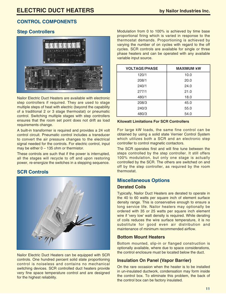
Nailor Electric Duct Heaters are available with electronicstep controllers if required. They are used to stagemultiple steps of heat with electric (beyond the capabilityof a traditional 2 or 3 stage thermostat) or pneumaticcontrol. Switching multiple stages with step controllersensures that the room set point does not drift as loadrequirements change.
A built-in transformer is required and provides a 24 voltcontrol circuit. Pneumatic control includes a transducerto convert the air pressure changes to the electricalsignal needed for the controls. For electric control, inputmay be either 0 – 135 ohm or thermistor.
These controls are such that if the power is interrupted,all the stages will recycle to off and upon restoringpower, re-energize the switches in a stepping sequence.
Modulation from 0 to 100% is achieved by time baseproportional firing which is varied in response to thethermostat demands. Proportioning is achieved byvarying the number of on cycles with regard to the offcycles. SCR controls are available for single or threephase heaters and can be operated with any availablevariable input source.
Nailor Electric Duct Heaters can be equipped with SCRcontrols. One hundred percent solid state proportioningcontrol is noiseless and contains no mechanicalswitching devices. SCR controlled duct heaters providevery fine space temperature control and are designedfor the highest reliability.
Kilowatt Limitations For SCR Controllers
VOLTAGE/PHASE MAXIMUM kW
120/1 10.0
208/1 20.0
240/1 24.0
277/1 21.0
480/1 18.0
208/3 45.0
240/3 55.0
480/3 54.0
Miscellaneous Options
Typically, Nailor Duct Heaters are derated to operate inthe 40 to 60 watts per square inch of element surfacedensity range. This is conservative enough to ensure along service life. Nailor heaters may optionally beordered with 35 or 25 watts per square inch elementwire if 'very low' watt density is required. While deratingof coils reduces the wire surface temperature, it is nosubstitute for good even air distribution andmaintenance of minimum recommended airflow.
Derated Coils
Bottom mounted, slip-in or flanged construction isoptionally available, where due to space considerations,the control enclosure must be located below the duct.
Bottom Mount Heaters
On the rare occasion when the heater is to be installedin un-insulated ductwork, condensation may form insidethe control box. To eliminate this problem, the back ofthe control box can be factory insulated.
Insulation On Panel (Vapor Barrier)

Notes:
Nailor Electric Duct Heaters are available in customsizes to suit any ductwork installation. Minimum size is8" x 6" (203 x 152). Maximum size is unlimited.
Control enclosures and control layouts are customcomputer designed for each heater. Sufficient space isprovided for the mounting and wiring of the requiredcomponents and to allow satisfactory heat dissipation.
They are furnished with left to right horizontal airflowand a left hand control panel overhang as standard(viewed when facing the panel). Standard position forthe control panel is on the right side of the element rackwhen looking in the direction of airflow. Refer to theillustrations on the submittal form (page 31) for thevarious optional configurations available.
Nailor Electric Duct Heaters are available in two basicdesigns:
Type DH – Slip-in (Standard)
CONSTRUCTION – DIMENSIONAL DATA
Slip-in (Standard)The standard unit is a slip-in (insertion) design. Suitablefor the majority of applications, the heater is installedinto existing ductwork through a rectangular cut-out inthe side of the duct. The duct cut-out should beapproximately 1/2" (13) larger than the heater elementrack depth and height for ease of installation.
The standard slip-in heater ordered by nominal duct sizeis built and undersized to accommodate the industrypredominant 1" (25) internal duct installation.
They are undersized approximately 1" (25) in width and2" (51) in height. This allows 1" (25) clearance aroundthe three sides of the element rack. For other insulationthicknesses, deduct one insulation thickness from theactual duct width and two insulation thicknesses fromthe actual duct height and order by heater (not duct)size.
Example: Duct size is 18" (457) W x 12" (305) H withstandard 1" (25) thick internal insulation. Standard slip-in heater is built as 17" (432) W x 10" (254) H.
ORDER HEATERS BY NOMINAL DUCT DIMENSIONSUNLESS THE DUCT IS UNINSULATED OR HASOTHER THAN 1" (25) INTERNAL INSULATION.
Flanged (Option)Flanges are turned out 1" (25) around three sides of theelement rack, providing a mounting surface for theheater and adding additional rigidity for larger ducts.Bolts are generally run through the matching duct(which should also be flanged on three sides) andheater flanges to support the weight of the heater.Additional screws through the control cabinet into theduct complete the installation.
ORDERS FOR FLANGED HEATERS MUST SPECIFYACTUAL DUCT SIZE.
B
CE
F
D
H
W
1"(25)
AIRFLOW
A
Type DH – Flanged (Option)
B
X
Y
CE
F
D
H
W
1/2"(13)
RIGHT OVERHANGOPTIONAL
AIRFLOW LEFT OVERHANGSTANDARD
A
ELECTRIC DUCT HEATERS by Nailor Industries Inc.
12
1a. For Slip-in:
W = Duct width – 1" (25).
H = Duct height – 2" (51).
B = H + 2" (51) standard.
X and Y = 1" (25) standard.
1b. For Flanged:
W and H = Duct size.
B = Duct height + 2" (51) standard.
2. F = 1" (25) standard.
3. A, B, C, D and E dimensions vary dependent uponcontrols.
If there is a critical dimension that the control panelmay not exceed due to clearance restrictions,please note this information on the order form, otherwise the computer designed control panel willbe supplied.
WIRING DIAGRAMS
AUTO RESET
MANUAL RESET
CONTACTOR
TRANSFORMER
AIRFLOW SWITCH
TERMINAL BLOCK
L1
L2
GND
C (BLUE - COMMON)
R (RED)
W (WHITE)
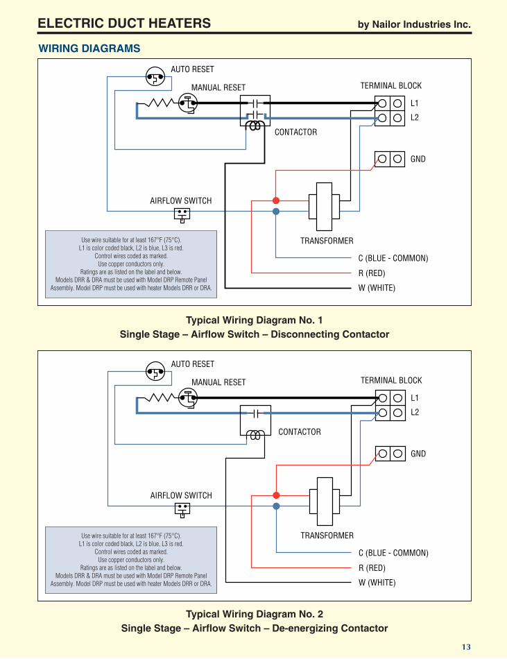
Use wire suitable for at least 167°F (75°C).L1 is color coded black, L2 is blue, L3 is red.
Control wires coded as marked.Use copper conductors only.
Ratings are as listed on the label and below.Models DRR & DRA must be used with Model DRP Remote Panel
Assembly. Model DRP must be used with heater Models DRR or DRA.
AUTO RESET
MANUAL RESET
CONTACTOR
TRANSFORMER
AIRFLOW SWITCH
TERMINAL BLOCK
L1
L2
GND
C (BLUE - COMMON)
R (RED)
W (WHITE)
Use wire suitable for at least 167°F (75°C).L1 is color coded black, L2 is blue, L3 is red.
Control wires coded as marked.Use copper conductors only.
Ratings are as listed on the label and below.Models DRR & DRA must be used with Model DRP Remote Panel
Assembly. Model DRP must be used with heater Models DRR or DRA.
Typical Wiring Diagram No. 1Single Stage – Airflow Switch – Disconnecting Contactor
Typical Wiring Diagram No. 2Single Stage – Airflow Switch – De-energizing Contactor
ELECTRIC DUCT HEATERS by Nailor Industries Inc.
13

WIRING DIAGRAMS
AUTO RESET LIMIT PE SWITCH AIRFLOW SWITCH
MANUAL RESET TERMINAL BLOCK
L1
L2
GND
Use wire suitable for at least 167°F (75°C).L1 is color coded black, L2 is blue, L3 is red.
Control wires coded as marked.Use copper conductors only.
Ratings are as listed on the label and below.Models DRR & DRA must be used with Model DRP Remote Panel
Assembly. Model DRP must be used with heater Models DRR or DRA.
AUTO RESET
MANUAL RESET
CONTACTOR
TRANSFORMER
AIRFLOW SWITCH
TERMINAL BLOCK
L1
L2
FANINTERLOCK
GND
C (BLUE - COMMON)
R (RED)
W (WHITE)
Use wire suitable for at least 167°F (75°C).L1 is color coded black, L2 is blue, L3 is red.
Control wires coded as marked.Use copper conductors only.
Ratings are as listed on the label and below.Models DRR & DRA must be used with Model DRP Remote Panel
Assembly. Model DRP must be used with heater Models DRR or DRA.
Typical Wiring Diagram No. 3Single Stage – Airflow Switch – Pneumatic Controls
Typical Wiring Diagram No. 4Single Stage – Fan Interlock – Contactor
ELECTRIC DUCT HEATERS by Nailor Industries Inc.
14

WIRING DIAGRAMS
TRANSFORMER
AIRFLOW SWITCH
WYE AUTO LIMIT
DELTACONTACTOR TERMINAL BLOCK
OPTIONAL NEUTRAL
L1
L2
L3
GND
C (BLUE - COMMON)
R (RED)
W (WHITE)
N
TRANSFORMER
AIRFLOW SWITCH
WYE AUTO LIMIT
DELTA BACK-UPCONTACTOR
TERMINAL BLOCK
OPTIONAL NEUTRAL
L1
L2
L3
GND
C (BLUE - COMMON)
R (RED)
DCCONTROLINPUT
N
+
SCR CONTROL
SCR CONTROL
Use wire suitable for at least 167°F (75°C).L1 is color coded black, L2 is blue, L3 is red.
Control wires coded as marked.Use copper conductors only.
Ratings are as listed on the label and below.Models DRR & DRA must be used with Model DRP Remote Panel
Assembly. Model DRP must be used with heater Models DRR or DRA.
Typical Wiring Diagram No. 5 – Three Phase Delta or WyeAirflow Switch – De-energizing Contactor – Transformer
Typical Wiring Diagram No. 6 – Three Phase Delta or Wye – Airflow SwitchDisconnecting Back-up Contactor – Transformer – SCR Control
ELECTRIC DUCT HEATERS by Nailor Industries Inc.
15
Use wire suitable for at least 167°F (75°C).L1 is color coded black, L2 is blue, L3 is red.
Control wires coded as marked.Use copper conductors only.
Ratings are as listed on the label and below.Models DRR & DRA must be used with Model DRP Remote Panel
Assembly. Model DRP must be used with heater Models DRR or DRA.

ENGINEERING – HEATER SELECTION
Voltage is the energy available to push the current throughthe element wire and overcome the resistance. It ismeasured in volts and is constant within a building. Voltagewithin a building is whatever the power company providesunless the building occupant changes it with a transformer.
Amperage is the current (the number of electrons) flowingthrough the element wire. Current is measured in ampsand depends on the voltage available and theresistance of the element wire.
Resistance is the resistance of the element wire. It ismeasured in Ohms. Resistance resists the flow ofelectrons and creates heat when voltage is applied tothe element wire. Copper wire is usually sized by theamount of current that will flow through it when theheater is operating.
Wattage is the power produced when current flowsthrough the element wire. Power is generally measuredin kilowatts (watts x 1000). Work is power per unit oftime, usually kW per hour for electric heaters. Powercompanies charge in units of kW-hours, or kW per hourx the number of hours the power was used.
Single Phase:The relationships between power, voltage, amperageand resistance are defined for single phase electricheaters as shown in the chart below.
IE
IR
IR
R
ER
2
2
2
2 E
E
R
EWW
I
W
W
WR
I
I
EI
WR
WEW
AT
T S AM
PS
SM
HO
OV
SL
T
ELECTRIC DUCT HEATERS by Nailor Industries Inc.
16
Three Phase:For three phase heaters, line current should be calculatedusing the following equation:
Amperes (I) = Watts (W)
Line Voltage (V) x 1.732
Calculating kW, Amps and Resistance
Ohms Law (applicable to single phase current).
∆T = kW x 3160
CFM
kW = CFM x ∆T
3160
CFM = kW x 3160
∆T
Where ∆T is the difference between discharge and inletair temperature (temperature rise T2 - T1) in °F.
The above equations are based upon standard air at13.33 ft3/lb. density and a specific heat of 0.237 BTU/lb. - °F.
Ex.: 10 kW heater, 20" x 10" duct, 1000 cfm, inlet air = 75°F.
1. Determine temperature rise/outlet temperature.
∆T = kW x 3160 = 10 x 3160 = 31.6°F
CFM 1000
Therefore, outlet air temperature = 75 + 31.6 = 106.6°F.
2. Determine heat requirement.
kW = CFM x (T2 - T1) = 1000 x (106.6 - 75) = 10.0 kW
3160 3160
3. Determine air volume.
CFM = kW x 3160 = 10 x 3160 = 1000 CFM
(T2 - T1) 106.6 - 75
Minimum Air VolumeMinimum airflow should be maintained at every point onthe face of the heater. Since an electric duct heatermaintains a constant BTU output while the heater isenergized, minimum air velocity through the heater mustbe maintained in order to: a) achieve good heat transfer; b) prevent over-heating and nuisance tripping of theprotection devices; and c) maintain life expectancy.Minimum acceptable uniform airflow across an electricduct heater is directly related to the temperature of the inletair. The table below shows the minimum volume of air perkW for different inlet air temperatures. For non-standard airconditions or if unusually low outdoor air temperatures areto be tempered by electric heat, consult Nailor.
Heat Capacity Calculations
INLET MINIMUM AIRFLOW INAIR CFM PER kW (FOR DUCT AREA
TEMPERATURE kW DENSITIES SHOWN)
°F °C ≤17 kW/sq. ft. ≤20 kW/sq. ft. ≤25 kW/sq. ft.85 29 90 110 15075 24 70 82 10355 13 50 55 6240 4 40 44 4825 -4 33 36 390 -18 27 28 30

Pressure Drop Through Heater (8" (203) Coil Depth)
ELECTRIC DUCT HEATERS by Nailor Industries Inc.
17
ENGINEERING – HEATER SELECTION
The maximum heat density permissible for NailorElectric Duct Heaters is 25 kW/square foot, as shown intable on the previous page.
Maximum Heater kW
Pressure DropStatic pressure drop through the duct heater may beconservatively estimated by using the 'Pressure DropThrough Heater' graph shown below. Pressure dropdepends on the number of rows of heating elementsand their density. This may vary widely dependent oncoil size and capacity. The graph is based on an 8"(203) coil depth and will suffice for most applications.
Typical Contactor Power Circuitry (only power circuit shown. Safety devices etc. omitted).
It is important to understand the difference between afull line break vs. a partial line break. In the partial linebreak arrangement, the contactor opens the currentpath, thus de-energizing the heater. De-energized elements deliver no heat but are electrically live. Thisarrangement is UL/CSA approved and because of itseconomy is offered as standard by Nailor. In order tomake servicing safe, the disconnect switch must beopened.
Some specifiers prefer, and some local electrical regulations require, the alternative full line break contactor arrangement. This may be ordered as anoption. Note that it is not safe to service even a full linebreak duct heater without opening the disconnectswitch.
The following diagrams present the most commonlyused arrangements.
De-energizing Type:
Heater is de-energized by breaking only one side of theline through the action of the single contact. This typewould be disconnecting for 120 V and 277 V.
THREEPHASE
SUPPLY
DELTAWYE
CONTACTOR
L1
L2
L3
SINGLEPHASE
SUPPLY
HEATINGELEMENTS
CONTACTOR
L1
L2
SINGLEPHASE
SUPPLY
HEATINGELEMENT
L1
L2CONTACTOR
SINGLEPHASE
SUPPLY
HEATINGELEMENTCONTACTOR
L1
L2
The above illustrates using a two pole contactor to de-energize one side of the line. This type of circuitrydoubles the contactor capacity. This type would bedisconnecting for 120 V and 277 V.
Heating power is completely disconnected by breakingboth sides of the power source. All ungrounded powerconductors are disconnected.
Illustrates a two line break which will de-energize theheater. Both Wye and Delta heating elementconfigurations are shown. Unless specified, optimumconfiguration is determined by Nailor.
All ungrounded conductors disconnected. Both Wye andDelta configurations shown.
One of several special element configurations. Thismethod allows element switching as a three phasebalanced load or each element may be operatedindependent ly through indiv idual contacts. Tocompletely disconnect heating elements from power, athree pole contactor must be used.
Disconnecting Type:
THREEPHASE
SUPPLY
DELTAWYE
CONTACTOR
L1
L2
L3
THREEPHASE
SUPPLYFOURWIRE
NEUTRAL
HEATINGELEMENTS
FOURWIREWYE
CONTACTOR
L1
L2
L3
N

18
ELECTRIC DUCT HEATERS by Nailor Industries Inc.
Number of Poles Required perContactor or Disconnect SwitchThe following table may be used to determine the number of poles required per contactor or discountswitch to either de-energize or disconnect.
Three Wire "Wye" Connection
ELEM
ENT
277 V
277 V
277 V
L1
L2IL2
IL1
IL3L3
N
480 V
480 V
480 V
NO. OF NUMBER OF POLESVOLTAGE PHASE OF TO TO
WIRES DE-ENERGIZE DISCONNECT120 2 1 1208 2 1 2240 1 2 1 2277 2 1 1480 2 1 2208 3 2 3208 4 3 3240 3 3 2 3480 3 2 3480 4 3 3
Heating Element Wiring Configurationsand Properties
1. Element Voltage = Line Voltage1.73
2. Phase Currents IL1 = IL2 = IL3.3. Voltage measured between any two power legs
(L1 to L2 etc.) should be equal to the three phase line voltage.
Four Wire "Wye" Connection
1. Element Voltage = Line Voltage1.73
2. Phase Currents IL1 = IL2 = IL3.3. The voltage between any power leg and neutral (N)
= Line Voltage1.73
4. Voltage measured between any two power legs (L1 to L2 etc.) should be equal to the three phase line voltage.
Heating elements, namely those used in three phase,balanced, configurations are factory wired, asmanufacturers standard in two basic configurations Delta orWye. A variation of Wye called 4 wire wye must be specified.
"Edison" Connection
1. Element Voltage = Line Voltage.
Formula For Calculating Line Currents
LINE VOLTAGE
HEAT
ING
ELEM
ENT(
S)
240 V
L1
L2
L1
L2
N
120 V
120 V
SINGLE PHASE:
Three Wire "Delta" Connection
1. Element Voltage = Line Voltage.2. Phase Currents IL1 = IL2 = IL3.3. Voltage measured between any two power legs
(L1 to L2 etc.) should be equal to the three phase line voltage.
THREE PHASE:
1. Element Voltage = Line Voltage
2
480 V FOR ILLUSTRATION ONLY
ELEM
ENT
480 V
L1
L2IL2
IL1
IL3L3
480 V
480 V
ELEM
ENT
480 V
L1
L2IL2
IL1
IL3L3
480 V
480 V
The following formula may be used to quickly determinetotal amps. It is common practice to select voltage/phase in order to keep total amps below 48 wherepossible and so eliminate the NEC requirement for circuit fusing and hence minimize heater cost.
Single Phase: Three Phase:120 V: kW x 8.333 = Total amps 208 V: kW x 2.776 = Total amps208 V: kW x 4.808 = Total amps 240 V: kW x 2.406 = Total amps240 V: kW x 4.167 = Total amps 460 V: kW x 1.255 = Total amps277 V: kW x 3.610 = Total amps 480 V: kW x 1.203 = Total amps480 V: kW x 2.083 = Total amps 600 V: kW x 0.962 = Total amps
Kilowatts = BTU's or MBH3,412 3.412

ELECTRIC DUCT HEATERS by Nailor Industries Inc.
When Electric Duct Heaters are used in preheat orreheat applications in plenums or casings, a specialstudy of the location is recommended. Irregular airflowpatterns are often found in the air movement throughoutside air louvers, filters, mixed air plenums andassociated dampers. At fresh air intakes, for example,the air entry should be rain-tight. As a precautionagainst water damage, it is recommended that thebottom elevation of the Electric Duct Heater be abovethe floor. Another important consideration is the safetyof individuals entering a plenum or casing chamber.Reasonable provisions for protection should be madeand these should include warning signs outside theelectric coil chamber.
Special LocationsAfter determining the use of a heater, a location in theair system must be selected that will permit satisfactoryperformance. The heater must be installed in a locationhaving suitable airflow characteristics. Where non-uniform airflow conditions exist at duct fittings, atequipment connections, at air terminals, or othersections, minimum lengths of straight runs of duct mustbe installed before and after the heater.
19
DUCT HEATER LOCATION
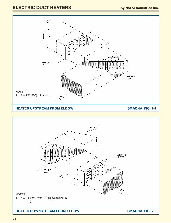
The preferred location for duct heaters adjacent toelbows is upstream of the elbow as illustrated in Figure7.7. When the heater must be downstream, Figure 7.8illustrates the minimum requirements.
Elbows
Electric heaters installed in a duct outlet downstreamfrom a heat pump, an air conditioning unit, or a fan unitmust comply with the minimum distances illustrated inFigures 7.15 and 7.16 unless the heater is specificallyapproved for installation at a lesser distance and is somarked.
Equipment
Branch connections are also particularly susceptible toturbulent airflow conditions. In order to reduce the needfor derated coils on the entering air side of the branchduct, the heater should be placed as far from the branchconnection as practicable and not less than theminimum distances illustrated in Figures 7.10, 7.11,7.12, 7.13 and 7.14. When the aspect ratio exceedsrecommended practice, the minimum distances from theheater to turbulent f low duct f i t t ings should beincreased.
Branch Ducts
Whenever electric duct heaters must be located neargrilles, registers or diffusers, the exposure and visibilityshould be evaluated. Increased spacing or the use of ascreen should be considered where protection againstprobes or other foreign objects is advisable or wherevisibility of the heater is objectionable. Figures 7.10,7.11, 7.12 and 7.14 illustrate the minimum recommendeddistance from a heater to a grille or register regardless ofthe length of the duct branch. Figure 7.9 illustrates the12" (305) minimum recommended distance that a heatershould have from the diffuser collar in a duct.
Grilles
When Electric Duct Heaters are to be located in fibrousglass ducts, the requirements for location are similar tothose for sheet metal ducts. For special installationdetails, see the "Installation" section of this catalog andFigures 7.4 and 7.5.
Fibrous Glass Ducts
Other factors to be considered in locating the heater are:
a) Heat loss from the duct before the tempered airreaches its destination.
b) The temperature and humidity of the spacesurrounding the heater. I f a section of ductcontaining an electric heater is installed in anatmosphere conducive to the collection of moistureeither inside the duct or on the outside of the duct,special provisions must be made to insure thatmoisture does not damage either the heater or thecontrols.
c) The accessibility of the heater and its control panel.Terminal boxes are often integral with the heaterand may exceed the height of the duct. The totalinstallation must be designed to accommodate thespace and access requirements of this component.Remote control panels may be used whereconditions dictate.
d) Hazards. To avoid damage and insure safety,special consideration must be given to the proximityof combustible material. Minimum clearancerequired by the manufacturer or applicable codes,whichever is greater, must be maintained.
Other Factors
Standard open coil Electric Duct Heaters are designedfor the elements to be in a horizontal position, whetherthe heater is installed in a horizontal duct or in a verticalduct. The coils would not be properly supported if theelements were oriented in the vertical posit ion.SPECIALLY CONSTRUCTED HEATERS AREAVAILABLE FOR VERTICAL INSTALLATION.
Heater Position
Reprint from SMACNA Ducted Electric Heat Guide for Air Handling Systems, 2nd Edition.

ELECTRIC DUCT HEATERS by Nailor Industries Inc.
Flanged heaters are connected to unlined and linedducts in the manner illustrated in Figure 7.1. For flowand performance considerations, the inside dimensionsof the duct must match the inside dimensions of theheater. Furthermore, on lined ducts, heaters must havewide flanges, insulated terminal boxes, and insulationon the exposed exterior of the frame.
On lined duct and insulated duct installations, terminalboxes should be provided with interior insulation.However, to prevent overheating of electrical components,the exterior of the terminal box should not be insulated.
Flanged HeatersDuct heaters rated 50 kW or less are normally suitablefor installation with zero distance between the heaterand combustible materials. Heaters larger than 50 kWshould be installed with regard to minimum spacingrequirements. (All Nailor Duct Heaters are rated for zeroclearance).
20
Reprint from SMACNA Ducted Electric Heat Guide for Air Handling Systems, 2nd Edition.
Clearance
Airflow direction is determined by facing the terminalbox side of the duct and should be specified for all typesof heater. The manufacturer and the installer shouldknow whether the airflow is horizontal (that is, to theright or left) or vertical (that is, up or down) since safetydevices are located differently in each case.Furthermore, since terminal boxes vary in width andsince space conditions may be limited, the terminal boxoverhang should be designed as left hand or right hand.
Airflow Direction
This section concerns the suspension, positioning,fastening and connecting of electric duct heaters.Certain additional features not covered elsewhere areincluded. Furthermore, although Figures 7.6 through7.16 i l lustrate f langed heaters, the installationrequirements are equally applicable to slip-in heaterinstallations.
DUCT HEATER INSTALLATION
Figure 7.2 illustrates a slip-in heater installation for bothlined duct and unlined duct.
For the lined duct, a sheet metal channel should beplaced on the interior surface of the lining to protect thelining and support the heater. Care should be exercisedto prevent tearing of penetration of the l ining. A recessed terminal box should be used in order to:
a) use the entire face of the heating elements; andb) correctly position the thermal cutouts.
Furthermore, to prevent condensation on lined duct andinsulated duct installations, terminal boxes should beprovided with interior insulation. However, to preventoverheating of electrical components, the exterior of theterminal box must not be insulated.
When a slip-in heater is necessarily smaller than thecross-sectional area of the duct as illustrated in Figure7.3, an equalizing grid should be used to maintainbypass air velocity at approximately the same rate asthe velocity through the heater. The grid (wire mesh orperforated plate) should have approximately the samefriction loss as the heater and should be fastened tothe sides of the duct.
Slip-In Heaters
Refer to SMACNA's Duct Construction Standards,Metal and Flexible for all sheet metal fabrication andconstruction details.
For installations in f ibrous glass ducts, refer toSMACNA's Fibrous Glass Duct Construction Standards.
If alternate corrections or locations are not availablewhen turbulent flow conditions exist and critically lowvelocities are experienced (or anticipated) in the ductcross-section on the entering side of the heater, a flowequalizing device (such as a perforated plate having50% or more free are) may be installed in the duct infront of the heater. However, consideration should begiven to the pressure drop that such a device will add tothe system.
When transitions are necessary on the inlet or outlet ofa heater, the flow must be controlled within the limitsillustrated in Figure 7.6.
The design of the installation must include adequateprovision for support of the duct heater.
Terminal boxes are integral with the heater and mayoften exceed the height of the duct. The total installationmust be designed to accommodate the space andaccess requirements of this component. Remote controlpanels may be used where condition dictates.
Airflow direction through the heater should be verifiedimmediately preceding installation in a duct. Particularattention should be given to the designated location ofbuilt-in thermal cut-outs.
Electric duct heaters are not generally designed forinstallation in series; that is, consecutively in a duct.This arrangement may be used in special applications inwhich the air temperature leaving the first heater doesnot exceed the maximum recommended air temperatureentering the second heater.
Access for servicing or for removal of electric ductheaters must be provided. When ducts are in concealedspaces, provision must be made for suitable accesspanels in walls or ceilings as necessary.
The installation should be reviewed for compliance withthe recommendations of the heater manufacturer.
General Requirements

ELECTRIC DUCT HEATERS by Nailor Industries Inc.
21
SMACNA FIG. 7-1
SMACNA FIG. 7-2
NOTES:1. H = H' and W = W'.2. To prevent condensation when duct is insulated use insulated terminal boxes.
NOTES:1. To prevent condensation when duct is insulated use insulated terminal boxes.2. R = Dimension of terminal box recess.
FLANGED DUCT HEATER
SLIP-IN DUCT HEATER

ELECTRIC DUCT HEATERS by Nailor Industries Inc.
22
SMACNA FIG. 7-3
SMACNA FIG. 7-4
NOTE:1. The equalizing grid should have the same pressure drop as the duct heater.
NOTES:1. A = 6" (152) minimum.2. Install hangers for sheet metal sleeves to adequately support the duct and heater.3. To prevent condensation when duct is insulated use insulated terminal boxes.
EQUALIZING GRID
FLANGED HEATER IN FIBROUS GLASS DUCT

ELECTRIC DUCT HEATERS by Nailor Industries Inc.
23
NOTES:1. A = 6" (152) minimum.2. Install hangers for sheet metal sleeves to adequately support the duct and heater.3. To prevent condensation use factory insulated terminal boxes.
NOTE:1. The illustrated angles of expansion and contraction
are the maximum recommended.
SLIP-IN HEATER IN FIBROUS GLASS DUCT SMACNA FIG. 7-5
DUCT TRANSITIONS – PLAN VIEW SMACNA FIG. 7-6
ELECTRIC DUCT HEATERS by Nailor Industries Inc.
24
NOTE:1. A = 12" (305) minimum.
NOTES:1. A = H + W with 12" (305) minimum.
2
SMACNA FIG. 7-7HEATER UPSTREAM FROM ELBOW
HEATER DOWNSTREAM FROM ELBOW SMACNA FIG. 7-8

ELECTRIC DUCT HEATERS by Nailor Industries Inc.
25
NOTE:1. A = 12" (305) minimum.
NOTES:1. A = H + W with 12" (305) minimum.
22. B = 6" (152) minimum.
SMACNA FIG. 7-9HEATER UPSTREAM FROM OUTLET CONNECTION
HEATER IN BRANCH DUCT SMACNA FIG. 7-10

ELECTRIC DUCT HEATERS by Nailor Industries Inc.
26
SMACNA FIG. 7-12
NOTES:1. A = H + W with 12" (305) min.
22. B = 6" (152) minimum.3. C = W
2
NOTES:1. A = H + W with 12" (305) min.
22. B = 6" (152) minimum.3. C = W
2
HEATER IN BRANCH DUCT SMACNA FIG. 7-11
HEATER IN BRANCH DUCT

HEATER IN DIVIDED DUCT
ELECTRIC DUCT HEATERS by Nailor Industries Inc.
27
SMACNA FIG. 7-13
HEATER IN DIVIDED DUCT SMACNA FIG. 7-14
NOTES:1. A = H + W with 12" (305) min.
22. B = 12" (305) minimum.
NOTES:1. A = H + W with 12" (305) min.
22. B = 6" (152) minimum.
HEATER IN DIVIDED DUCT

ELECTRIC DUCT HEATERS by Nailor Industries Inc.
28
NOTES:1. A = H + W with 48" (1219) minimum for heat pumps and air conditioners and with 24" (610) minimum for fan units.
22. Angles Y are 20° maximum.
NOTES:1. A = H + W with 48" (1219) minimum for heat pumps and air conditioners and with 24" (610) minimum for fan units.
22. B = 12" (305) minimum.3. Angles Y and Z are 20° maximum for all units.
SMACNA FIG. 7-15HEATER DOWNSTREAM FROM AIR HANDLER
HEATER DOWNSTREAM FROM AIR HANDLER SMACNA FIG. 7-16

National Electric Code (NEC) and UL 1996 Requirements for Duct Heaters
(UL 1996 22.10) "If the transformer is Class 2,compliance with 22.9 is not required."
(UL 1996 22.12) "Overcurrent protection in thesecondary circuit of a transformer ... shall be providedas part of the equipment."
Location of Disconnecting Means:
ELECTRIC DUCT HEATERS by Nailor Industries Inc.
29
(NEC 424-65) "Duct heater controller equipment shallbe accessible with the disconnecting means installed ator within sight of the controller."
(UL 1996 23.2.1)
"A duct heater employing resistance type heatingelements shall be protected at no more than 60amperes, and the protected circuit shall not have aconcurrent load exceeding 48 amperes. These heatingelements shall be connected in protected subdividedcircuits if any total concurrent load of the unit exceeds48 amperes based on nameplate ratings. If the over-current protective devices are in a separate assemblyfor independent mounting, ... the rating of the over-current protective devices also shall not exceed 1.5times the current rating of the connected load, if suchrating is more than 16.7 amperes."
(UL 1996 23.2.3) "the overcurrent protection specified in23.2.1 and 23.2.2 shall be circuit breakers, cartridgefuses, or type S plug fuses, of a type and ratingappropriate for branch circuit protection, in accordancewith the requirements of the National Electric Code,ANSI/NFPA 70-1990. Plug fuses shall not be used incircuits exceeding 150 V to ground; screw shells of plugfuses shall be connected to the load side of the circuit."
Overcurrent Protection:
Transformer Overcurrent Protection:(UL 1996 22.7) " ... a transformer having a high voltageprimary shall be protected by an overcurrent device(or devices) located in the primary circuit, and rated orset as indicated in Table 22.1."
(UL 1996 21.5) "A duct heater shall have terminal orleads for field connection of an interlock circuit for acirculating fan motor unless an airflow interlock isprovided as an integral part of the heater and arrangedso that no heating element circuit can be energizedunless the interlocking contacts are closed or theinterlocking power supply energized. This does notpreclude the use of a fan delay control that complieswith the applicable requirements for a fan control."
Transformer Grounding:(UL 1996 22.15) "The secondary of a transformersupplying power to low-voltage circuits shall be groundedif: a) The primary is energized from a source rated atmore than 150 volts-to-ground; or b) It supplies power toa control circuit that is a safety circuit."
Fan Control:
(UL 1996 22.9) "Except as indicated in 22.10, atransformer having a rated output of not more than 30volts and 100 volt-amperes shall be protected by anovercurrent device located in the primary circuit. Theovercurrent device shall be rated or set at not more than167% of the primary current rating of the transformer."
Rated PrimaryMaximum rating of
Current.overcurrent device.
(Amps)(percent of transformer primary current rating)
less than 2 300%
2 to less than 9 167%
9 or more 1.25%
Table 22.1 Rating of Overcurrent Device

ELECTRIC DUCT HEATERS by Nailor Industries Inc.
30
OP
TIO
NA
L A
CC
ES
SO
RIE
S:
1.A
ir P
ress
ure
Sw
itch
2.F
an R
elay
3.M
anua
l Res
et L
imits
4.In
sula
tion
On
Pan
el5.
Con
trol
Tra
nsfo
rmer
(C
lass
2)
6.C
ontr
ol T
rans
form
er (
Fus
ed)
7.C
ircui
t Fus
ing
per
NE
C8.
Circ
uit F
usin
g in
exc
ess
of N
EC
req
.9.
Circ
uit B
reak
ers
10.
Dis
conn
ect S
witc
h (T
oggl
e)11
.D
isco
nnec
t Sw
itch
(Doo
r In
t.)12
.Q
uiet
Con
tact
ors
13.
Mer
cury
Con
tact
ors
(Lis
t by
num
ber)
14
.P
E S
witc
hes
15.
Ste
p C
ontr
olle
r16
.S
CR
Con
trol
ler
17.
Bac
k-up
Con
tact
ors
18.
Pilo
t Lig
ht19
.P
ilot R
elay
20.
Pilo
t (T
oggl
e) S
witc
h21
.80
–20
Wire
22.
Rec
esse
d T
erm
inal
Box
23.
Wea
ther
Pro
tect
ed P
anel
24.
Fla
nged
Hea
ter
25.
Der
ated
Coi
ls26
.T
op o
r B
otto
m B
ox
DUCT
SIZ
EHE
ATER
SIZ
ELI
NECO
NTRO
LHE
ATER
DIM
ENSI
ONS
(IF C
RITI
CAL)
FIG.
ACCE
SSOR
IES
TAG
QTY.
MOD
ELKW
W x
HW
x H
VOLT
SPH
VOLT
AGE
STG.
AB
CD
EF
XY
NO.
(LIS
T BY
NUM
BER)
SLIP
-INST
ANDA
RDHE
ATER
WC
B
X Y
H
FLAN
GED
HEAT
ER
SLIP
-INTO
P VI
EW
FLAN
GED
TOP
VIEW
W
B
X Y
H
A
EF
D
A
E
D
F
AW ST
ANDA
RDAI
RFLO
WE
D
F
C
A
EF
D
W STAN
DARD
AIRF
LOW
C
Sta
ndar
d C
onst
ruct
ion:
X, Y
& F
= 1
" (2
5)
Sta
ndar
d S
lip-in
:
Hea
ter
is a
ppro
xim
atel
y1"
(25
) sm
alle
r th
an th
edu
ct.
EL
EC
TR
IC D
UC
T H
EA
TE
R S
UB
MIT
TAL
FO
RM
Dat
e:
Cu
sto
mer
:P
.O. N
o.:
Pro
ject
:P
age
of
Nailo
rIn
du
str
ies
In
c.

HEATER CONFIGURATIONS
AIRFLOW
LEFT PANEL OVERHANG
ELECTRIC DUCT HEATERS by Nailor Industries Inc.
31
Top View Top View
Top View Top View
Top View Top View
Top View Top View
AIRFLOW
RIGHT PANEL OVERHANG
AIRFLOW
RIGHT PANEL OVERHANG
AIRFLOW
LEFT PANEL OVERHANG
AIRFLOW
LEFT PANEL OVERHANG
AIRFLOW
LEFT PANEL OVERHANG
AIRFLOW
RIGHT PANEL OVERHANG
AIRFLOW
RIGHT PANEL OVERHANG
AIRFLOWAIRFLOW
Top View Top View
Fig. 1 Slip-in Heater (standard). Fig. 2 Slip-in Heater (option).
Fig. 4 Slip-in Heater (option).Fig. 3 Slip-in Heater (option).
Fig. 5 Flanged Heater (standard). Fig. 6 Flanged Heater (option).
Fig. 7 Flanged Heater (option). Fig. 8 Flanged Heater (option).
Fig. 9 Flanged Heater with Full Sleeve (option). Fig. 10 Flanged Heater with Full Sleeve (option).

SUGGESTED SPECIFICATIONS
DH – R9.03
Electric Duct Heaters shall be of the size, type and
capacity as shown on the drawings.
Heaters shall be ETL listed for zero clearance from
all combustibles and shall bear the ETL listing mark.
Each heater shall meet the requirements of NEC
and shall be of the open coil design and shall be as
manufactured by Nailor Industries, Inc.
Each heater shall be furnished with two levels of
over temperature safety devices serviceable and/or
replaceable in the terminal box without removing the
heater from the duct. The primary safety device
shall be a disc type automatic reset that will cut the
heater off on an over-temperature condition and
automatically bring the heater back on when the
condition is corrected. The secondary safety device
shall be of the disc type, manually resettable or
replaceable, and wired in the power lines in series
with the heater elements such that failure of a
sufficient number of these devices will de-energize
or disconnect the heater until service is rendered if
the primary device should fail.
The heater terminal box and frame shall be of heavy
gauge (minimum 20 gauge) galvanized steel
sufficiently formed and braced to assure structural
rigidity of the entire heater assembly. Terminal box
and lid must be totally enclosed and free from any
perforations or louvers. The terminal box shall have
Nailor sub-panel design for greater cooling effect and
rigidity.
Elements shall be of high grade nickel chrome alloy.
Elements shall be held in place with high grade
ceramic insulators that expose the entire heating
element to the air stream. Brackets shall be of
sufficient strength so the element wire, when in
place, cannot cause brackets to bend.
Each heater shall be furnished with an exact 'as is'
wiring diagram. Typical wiring diagrams are not
acceptable.
Heaters shall be constructed as slip-in, flanged, top
or bottom boxes as shown on the drawings.
Built-in components shall include:
(write in the desired options)
1. Built-in Air Pressure Switch or Fan Interlock
Relay. (Specifier select one).
2. Magnetic Contactors, Quiet Contactors or
Mercury Contactors for silent operation or
excessive switching. (Specifier select one).
3. Manual reset or one time fusible link secondary
hi-limit protection. (Specifier select one).
4. Insulated Terminal Box
5. Control Transformer
6. Overcurrent Protection as required by NEC and
UL (on heaters over 48 amperes), or
Overcurrent Protection for each stage, or
Overcurrent Protection for all heaters regardless
of amp ratings. (Specifier select one).
7. Circuit Breakers in lieu of fuses for any of the
above.
8. Built-in Disconnect Switches that will disconnect
all power lines prior to the heater control
enclosure opening.
9. Pneumatic Electric Switches factory mounted
and wired for each stage.
10. Electronic Step Controllers with modulating
thermostats that will control each stage of heat.
11. SCR Controllers complete with back-up
contactors and factory supplied thermostats that
will modulate the heat output of the heaters from
0 to 100% as required by the room thermostat.
12. Pilot Lights showing:
heater on or
stages on or
Airflow Switch off, etc.
13. Pilot relays to switch heater stages as required
from building controls.
14. Toggle Switches to manually operate or lock-out
stages of heat.
15. Heaters so specified on the drawings or in the
schedules shall be supplied with remote control
panels manufactured by the heater manufacturer
for use with the heaters.
Calgary, CanadaTel: 403-279-8619
Fax: 403-279-5035
Houston, TexasTel: 281-590-1172
Fax: 281-590-3086
Las Vegas, NevadaTel: 702-648-5400
Fax: 702-638-0400
Toronto, CanadaTel: 416-744-3300
Fax: 416-744-3360