dual phase separation for synthesis of bimodal meso-/macroporous carbon monoliths
TRANSCRIPT

Dual Phase Separation for Synthesis of Bimodal Meso-/MacroporousCarbon Monoliths
Chengdu Liang and Sheng Dai*
Chemical Sciences DiVision and Center for Nanophase Materials Sciences, Oak Ridge NationalLaboratory, Oak Ridge, Tennessee 37831-2601
ReceiVed February 5, 2009. ReVised Manuscript ReceiVed March 9, 2009
Polymerization-induced spinodal decomposition was conducted in glycolic solutions of phloroglucinol/formaldehyde copolymer and poly(ethylene oxide)-poly(propylene oxide)-poly(ethylene oxide)(PEO-PPO-PEO) to synthesize bicontinuous macroporous morphologies with microdomains from 0.5to 6 µm. The polymeric materials were further carbonized at elevated temperature to yield bimodal meso-/macroporous carbon monoliths after the thermal decomposition of the PEO-PPO-PEO template. Thebimodal porous nature of the resultant carbon monoliths was derived from the dual phase separation inwhich spinodal decomposition and microphase separation occurred simultaneously. We demonstratedthe tunability of macropores without alteration of mesopore sizes.
Introduction
The immense scientific and commercial value of porouscarbon materials is illustrated by their ubiquity as keymaterials in fuel cells, batteries, catalysts, and separationmedia.1 The combination of meso- and macroporosities inbimodal porous carbons confers enhanced electronic,2,3
mechanical,3 and mass-transport4 properties to sorbents dueto the facilitated mass transport through the macropores whilefurnishing a high specific surface area through mesopores.5
Mesoporous carbons are traditionally synthesized throughvarious activation methods, which result in carbons of broadpore-size distributions (PSD) with complementary micro- andmacropores. In recent years, the template-assisted synthesisopens an avenue for rational synthesis of mesoporous carbonwith well-controlled pore sizes, morphologies, and sym-metries.1 According to the nature of templates, synthesismethods can be classified as hard-template6 and soft-templatesynthesis.1 The hard-template synthesis, also known asnanocasting, uses presynthesized mesoporous oxides andnanoparticles to shape the resultant carbon materials and thepores are formed after chemical etching of the hard templates.While the hard-template synthesis suffers from a tediousprocedure during the preparation and removal of templates,soft-templates synthesis offers a handy synthesis approachthrough the self-assembly of carbon precursors with blockcopolymers and surfactants, which are sacrificed as porogensduring carbonization. The underpinning physics of block
copolymer self-assembly is the microphase separation,7
which has been well-documented over the past few decades.A large variety of highly ordered mesoporous materials weresynthesized by using the microphase separation phenomenonof block copolymers.
Spinodal decomposition is a well-established phase sepa-ration method for the synthesis of macroporous polymerswith a macropore size in the low micrometer range.8 Toinduce phase separation in a polymer system, two basicmethods have developed. One is thermally induced phaseseparation and another is chemically induced phase separa-tion.8 Thermally induced phase separation is carried out ina polymer solution in which the phase diagram exhibits anupper critical solution temperature. The polymer forms ahomogeneous solution when it has been heated to the uppercritical solution temperature. The homogeneous solution canbe induced to phase separation by thermal quenching to fallinto the binodal or spinodal line, thus resulting in a two-phase morphology. Depending on the quench rate and thecomposition, phase separation occurs via either nucleationand growth or spinodal decomposition. Complete knowledgeof kinetics and thermodynamics is required for control ofthe phase separation system. Because of the limit of heat-exchange rates, thermally induced phase separation is suitableonly for the preparation of thin films, where a fast heattransfer from a heated solution to the environment can beachieved. Chemically induced phase separation is also calledpolymerization-induced phase separation.9-13 To carry outthe chemically induced phase separation, reactive precursors
* Corresponding author. E-mail: [email protected].(1) Liang, C.; Li, Z.; Dai, S. Angew. Chem., Int. Ed. 2008, 47, 3696–
3717.(2) Wang, D. W.; Li, F.; Liu, M.; Lu, G. Q.; Cheng, H. M. Angew. Chem.,
Int. Ed. 2008, 47, 373–376.(3) Wang, Z. Y.; Li, F.; Ergang, N. S.; Stein, A. Chem. Mater. 2006, 18,
5543–5553.(4) Liang, C. D.; Dai, S.; Guiochon, G. Anal. Chem. 2003, 75, 4904–
4912.(5) Nakanishi, K.; Tanaka, N. Acc. Chem. Res. 2007, 40, 863–873.(6) Ryoo, R.; Joo, S. H.; Kruk, M.; Jaroniec, M. AdV. Mater. 2001, 13,
677–681.
(7) Bates, F. S.; Fredrickson, G. H. Annu. ReV. Phys. Chem. 1990, 41,525–557.
(8) Kiefer, J.; Hedrick, J. L.; Hilborn, J. G. In Macromolecular Archi-tectures; Springer-Verlag: Berlin, 1999; Vol. 147, pp 161-247.
(9) Fond, C.; Kiefer, J.; Mendels, D.; Ferrer, J. B.; Kausch, H. H.; Hilborn,J. G. J. Mater. Sci. 1998, 33, 3975–3984.
(10) Kiefer, J.; Kausch, H. H.; Hilborn, J. G. Polym. Bull. 1997, 38, 477–483.
(11) Kiefer, J.; Hilborn, J. G.; Hedrick, J. L. Polymer 1996, 37, 5715–5725.
2115Chem. Mater. 2009, 21, 2115–2124
10.1021/cm900344h CCC: $40.75 2009 American Chemical SocietyPublished on Web 04/27/2009
are mixed with nonreactive low molecular weight or oligo-meric solvents. The selection of a solvent or a mixture ofsolvents is very crucial, as a moderate solvent is requiredfor the reactive precursors to give a homogeneous solutionin the initial stage and becomes an immiscible solvent forthe polymerized reactive precursors to obtain a phase-separated final morphology. Unlike the thermally inducedphase separation that develops in a very rapid thermalquenching process, chemically induced phase separation isa relatively slow process in which the phase separationdevelops progressively during the polymerization of theprecursor. The growth or cross-linking of the polymer chainsresults in the immiscibility of the cured polymer and thenonreactive solvents. Consequently, the initial solvent be-comes a nonsolvent in liquid droplets to form a secondaryphase, which eventually forms voids for the cured porouspolymer. The chemically induced phase separation is lessunderstood than thermally induced phase separation due tothe theoretical complexity of this method.8 Nonetheless,chemically induced phase separation has been widely utilizedin the preparation of porous polymers in forms from thinfilms to large monoliths. When poly(furfuryl alcohol), apolymericcarbonprecursor,wasemployed,uniformmacroporesthat developed in the spinodal decomposition process wereretained after pyrolysis at a temperature higher than 800 °C.Uniform macroporous carbons were successfully preparedwith controlled pore sizes from 0.5 to 5 µm.14
A dual phase separation process,5 which combines themicrophase separation and spinodal decomposition, was firstreported as a versatile method for the synthesis of bimodalporous silicate and hybrid silicate materials that have ahierarchical porosity of two discrete length scales in nanom-eters and micrometers. The hierarchically meso-/macroporos-ity of these silicate materials results from the concurrentpresence of microphase separation and spinodal decomposi-tion. Later on, we patented the dual phase separation methodfor the synthesis of carbon monolith with an application formonolithic liquid chromatography columns.15 Althoughbimodal porous carbon can be synthesized through replicationof bimodal porous silica monolith16,17 and combined hard-softtemplating synthesis,18 a one-step synthesis could simplifythe synthesis procedure as reported by Zhao and co-workerswith a hydrothermal synthesis process.19 In spite of thesimplicity of the synthesis procedure, the dual phase separa-tion synthesis has its complex physiochemical changesresulting from the coupled phase separations. Due to thelimited publications about this emerging method, the physicsof the dual phase separation is largely unknown. How do
the two phase separations interplay with each other? Howcan this dual phase separation phenomenon be harnessed forcontrolled synthesis of materials by design? We report hereina facile synthesis approach for bimodal porous carbonthrough a dual phase separation process by which thetunability of the macropores was demonstrated while the sizeof the mesopores remained unchanged.
Experimental Section
Chemicals. Triblock poly(ethylene oxide)-b-poly(propylene oxide)-b-poly(ethylene oxide) copolymer Pluronic F127 (EO106PO70EO106,Mv ) 12600), ethylene glycol (EG), diethylene glycol (DEG),triethylene glycol (TEG), and tetraethylene glycol (TetraEG),hydrochloride acid (37 wt % aqueous solution), phloroglucinol(HPLC grade), and formaldehyde (37 wt % aqueous solution) werepurchased from Aldrich. Ethanol (200 proof) was a product ofPharmco Aaper Inc. distributed by ORNL local store. Deionized(DI) water was generated by a Millipore water purification system.All chemicals were used as received.
Synthesis of Polymeric Materials. A prepolymerization stepwas conducted for the synthesis of a polymeric mixture ofphloroglucinol/formaldehyde copolymer and triblock copolymerF127 according to a previous publication.20 Briefly, 1.26 g ofphloroglucinol, 1.26 g of F127, 0.1 g of 37 wt % hydrochlorideacid solution, 5 g of ethanol, and 4 g of water were mixed andstirred until they became a homogeneous solution with a water bathat 30 °C. Subsequently, 1.3 g of formaldehyde (37 wt % aqueoussolution) was added to the mixture under stirring. The prepoly-merization was conducted for 30-90 min. The duration ofprepolymerization was recorded as T1. The polymer phase wasseparated from the solvents after the polymerization by centrifuga-tion at 9500 rpm for 5 min. A portion of prepolymerized mixturewas then dissolved in glycolic solvents and immediately transferredinto a glass tube (7 mm inner diameter, 30 cm long). The glasstube was sealed and placed in an air bath heated at temperaturesspecified in Table 1. All samples were heated in the air bath for12 h with exception of sample MC18, which was washed with
(12) Kiefer, J.; Hilborn, J. G.; Manson, J. A. E.; Leterrier, Y.; Hedrick,J. L. Macromolecules 1996, 29, 4158–4160.
(13) Pascault, J. P. Macromol. Symp. 1995, 93, 43–51.(14) Constant, K. P.; Lee, J. R.; Chiang, Y. M. J. Mater. Res. 1996, 11,
2338–2345.(15) Dai, S.; Guiochon, G. A.; Liang, C. Robust carbon monolith having
hierarchical porosity. U.S. Patent 7449165, Nov 11, 2008; 2005169829.(16) Taguchi, A.; Smatt, J. H.; Linden, M. AdV. Mater. 2003, 15, 1209–
1211.(17) Shi, Z. G.; Feng, Y. Q.; Xu, L.; Da, S. L.; Zhang, M. Carbon 2003,
41, 2677–2679.(18) Alvarez, S.; Fuertes, A. B. Mater. Lett. 2007, 61, 2378–2381.(19) Huang, Y.; Cai, H. Q.; Feng, D.; Gu, D.; Deng, Y. H.; Tu, B.; Wang,
H. T.; Webley, P. A.; Zhao, D. Y. Chem. Commun. 2008, 2641–2643.
(20) (a) Liang, C. D.; Dai, S. J. Am. Chem. Soc. 2006, 128, 5316–5317.(b) Wang, X. Q.; Liang, C. D.; Dai, S. Langmuir 2008, 24, 7500–7505.
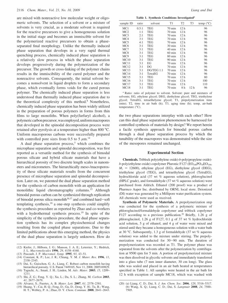
Table 1. Synthesis Conditions Investigateda
sample ID ratio solvent T1 T2 T3 temp (°C)
MC1 0.5:1 TEG 70 min 12 h 96MC2 1:1 TEG 70 min 12 h 96MC3 2:1 TEG 70 min 12 h 96MC4 3:1 TEG 70 min 12 h 96MC5 4:1 TEG 70 min 12 h 96MC6 3:1 TEG 30 min 12 h 96MC7 3:1 TEG 40 min 12 h 96MC8 3:1 TEG 60 min 12 h 96MC9 3:1 TEG 80 min 12 h 96MC10 3:1 TEG 90 min 12 h 96MC11 3:1 EG 70 min 12 h 96MC12 3:1 DG 70 min 12 h 96MC13 3:1 DG/TEG 1:1 70 min 12 h 96MC14 3:1 TetraEG 70 min 12 h 96MC15 3:1 TEG 70 min 12 h 80MC16 3:1 TEG 70 min 12 h 100MC17 3:1 TEG 70 min 12 h 110MC18 3:1 TEG 70 min 8 h 12 h 96a Ratio: ratio of polymer to solvent. Solvent: pure and mixtures of
solvents; EG, ethylene glycol; DEG, diethylene glycol; TEG, triethyleneglycol; TetraEG, tetraethelyene glycol; T1, prepolymerization time(min); T2, time in air bath (h); T3, aging time (h); temp, air-bathtemperature (°C).
2116 Chem. Mater., Vol. 21, No. 10, 2009 Liang and Dai

copious TEG after being heated for 8 h and then aged in TEG at100 °C for 12 h. After the polymer rods were released from theglass tubes, the fluffy precipitates on the rod surfaces were wipedoff. The glycolic solvents were washed off by soaking the samplesin ethanol for 4 h and then exchanged with DI water. All rods weredried in air for 4 h and then held inside a glass tube dried at 100°C overnight. The detailed synthesis conditions were tabulated inTable 1.
Carbonization. Each polymer rod was held inside a fused silicatube with an inner diameter slightly larger than the outer diameterof the polymer rod. The polymer rods along with the silica tubeswere then loaded into a tube furnace (Thermolyne, Model 79300).A stream of house nitrogen was fed through one end of the tubefurnace at 50 sccm during the entire course of carbonization. Thesamples were heated to 850 at 2 °C/min and held at 850 °C for2 h. All samples were unloaded after the furnace cooled down toroom temperature.
High-Temperature Treatment. The high-temperature treatmentwas conduced on a graphite furnace (Thermal Technology Inc.,Model 1000-2560-P20). All samples were degassed through threecycles of evacuation and refilling of helium gas after they had beenloaded into the furnace. The heating treatment was carried out at aslightly positive pressure of 5 mmHg under the protection of ahelium stream at 5 sccm. The furnace was ramped to 2600 at 40°C/min and held for 1 h. Samples were discharged after the heatingchamber cooled to room temperature.
Characterization. The low-magnification images were taken ina scanning electron microscope (SEM, Model JEOL 6060) systemthat operated at 15 kV. The high-magnification images were imagedby a scanning transmission electron microscope (STEM HD-2000).Small pieces of sample were sandwiched between two transmissionelectron microscopic (TEM) grids and loaded into the columnthrough a standard TEM sample holder. The STEM unit wasoperated at an electron accelerating voltage of 200 kV and anemission current of 30 µA. Nitrogen sorption isotherms of theporous carbons were measured at 77 K using a Micromeritic Gemini275 system. The specific surface areas and pore size distributionswere calculated by using the Brunauer-Emmett-Teller (BET)theory and the Barrett-Joyner-Halenda (BJH) method based onthe adsorption branches of the isotherms. The specific pore volumeswere measured at relative pressure 0.95. The thermogravimetricanalysis (TGA) was conducted on a TA Q-500 TGA system (TAInstruments). Platinum pans were preheated to 1000 °C in air for2 h and cooled to room temperature prior to loading of the samples.All TGA measurements were run under nitrogen from roomtemperature to 850 °C through a ramp of 2 °C/min. Powder X-raydiffraction (PXRD) patterns were recorded on a PANalytical X’pertPRO 2-circle X-ray diffractometer. The samples were ground by amortar and pestle and loaded onto a silicon zero-background sampleholder.
Results
General Description of Bimodal Porous CarbonMonolith. The representative microstructure of a typicalbimodal porous carbon is shown in Figure 1 B,C, whichreveal a bicontinuous network of carbon with a macroporesize of ∼3 µm, skeletal size of 1 µm, and mesopores of 8nm. The network fully developed after the polymerizationas shown in the comparison between parts (A) and (B) ofFigure 1, which were taken from the polymeric materialbefore carbonization and the carbon material resulting fromcarbonization of the polymeric material, respectively. Themicrostructural patterns in Figure 1A,B are similar but the
size of the domains in Figure 1 B is smaller than that inFigure 1A because of the dimensional shrinkage uponcarbonization. The mesopores in the skeleton of the carbonwas visualized by a high-resolution SEM image in Figure1C. Because a directly micrographic comparison of thepolymer skeleton and carbon skeleton was difficult to makedue to the severe charging of the polymeric materials underhigh-resolution SEM, the mesopores were measured andcompared by BET measurements of N2 uptake at 77 K. Theisotherms were plotted in Figure 2. The polymer rods (dottedblue line) adsorbed a negligible amount of N2, while thecarbonized sample (heated to 850 °C, solid black line) andgraphitized sample (heated to 2600 °C, dashed red line)showed sharp steps of N2 uptake at relative pressure between0.6 and 0.8. Evidently, the mesopores developed aftercarbonization.
The sizes and morphologies of the macropores andskeletons of the resulting carbons depend on the synthesis
Figure 1. Microstructure of sample MC4: (A) bicontinuous network of thepolymeric material before carbonization; the image was taken after physicalvapor deposition of gold for the elimination of charging. (B) Bicontinuousnetwork of carbon. (C) Mesopores on the skeleton of the carbonized sample.Scale bars are specified in images.
2117Chem. Mater., Vol. 21, No. 10, 2009Bimodal Meso-/Macroporous Carbon Monoliths

conditions. We set sample MC4 as a reference recipe forthe synthesis condition. Based on the reference, we system-atically investigated the major factors that significantlyaffected the phase separation, including the duration ofprepolymerization, solvent, ratio of solvent to polymer, andtemperature. Wall effect was observed and eliminated by anoptimized synthesis condition. A complete description of theresulting carbon was summarized in Table 2 includingcharacteristics of the microstructures and the time when theclouding point appeared after being heated in the air bath.The morphologies of macropores were described in detailaccording to the factors under investigation.
Morphologies of Macropores and Skeletons. Effect ofPrepolymerization. F127 is sparely soluble in the glycolicsolvents under investigation at room temperature. Thesolubility of F127 in the glycolic solvents at elevatedtemperatures was not measured, but we observed twoimmiscible layers of liquids when the mixture of 1:4 (weightratio) of F127 and glycolic solvents was heated to thetemperature between 60 and 140 °C. After F127 andphloroglucinol were premixed and prepolymerized withformaldehyde in an ethanolic solution as we reportedelsewhere,20 The polymer mixture that separated from theethanolic solution contained F127, oligomers of phloroglu-cinol/formaldehyde, and a small amount of ethanol and water.The resulting polymer mixture was miscible with glycolicsolvents when the duration of prepolymerization was shorterthan 120 min. The viscosity of the polymer mixture was afunction of prepolymerization time. The long prepolymer-ization time resulted in viscous polymer mixtures due to theincrease of average molecular weight of the phloroglucinol-formaldehyde oligomers. Apparently, small-size oligomersof phloroglucinol-formaldehyde promoted the miscibilityof F127 and glycolic solvents. The duration of the prepo-lymerization affected the morphologies of the resultingpolymer rods and the carbon monoliths. Samples MC6, MC7,MC8, MC4, MC9, and MC10 were synthesized with thesame composition but with different durations of prepoly-
merization from 30 to 90 min. Figure 3 shows the morphol-ogies of carbons resulting for MC6, MC7, MC8, MC4, MC9,and MC10. MC6 was prepolymerized for 30 min. Thissample has the morphology of loose spherical particles witha broad size distribution from 1 to 20 µm (Figure 3A). Whenthe duration of prepolymerization increased to above 40 min,the resulting materials shown from Figure 3B to Figure 4Fhave bicontinuous morphologies. The skeletal size of thecarbon domains decreased while the prepolymerization timeincreased. Secondary phase separations were observed insamples MC7 and MC8, which were prepolymerized for 40and 60 min, respectively. Spherical pores of about 1 µmpresented in the skeleton of MC7. The spherical pores werevoids left by the solvents that separated out in the polymer-rich domain as a result of the secondary phase separation.Carbon spheres were seen on the surface of the skeleton.Most likely, these carbon spheres were resulting from thesecondary phase separation of polymers in the solvent-richdomain. These spherical particles landed on the surface ofthe skeleton after the removal of the glycolic solvents. Thetexture of MC8 is much finer than that of MC7. Althoughno macropore was observed on the skeleton, a few sphericalparticles that landed on the surface of the skeleton indicatedthe secondary phase separation in the solvent-rich phase. Nosecondary phase separation occurred in samples MC4, MC9,and MC10.
Influence of SolVent. Inspired by the work of Chiang andco-workers, who successfully synthesized macroporouscarbon monoliths via a macrophase separation of poly(fur-furyl alcohol) in triethylene glycol, we also utilized trieth-ylene glycol and its derivatives as solvents for inducingmacrophase separation in our phenolic polymer system. Thesimilarity in the hydrophilicity of the furfuryl alcoholpolymer system to that of our phenolic polymer system formsthe key rationale for us to choose triethylene glycol andrelated solvents. Four glycolic solvents, ethylene glycol (EG),diethylene glycol (DEG), triethylene glycol (TEG), andtetraethylene glycol (TetraEG), were invested in the synthe-sis. Phase separation was observed when the polymerizationwas conduced in EG, DEG, TEG, and the mixture of DEGand TEG. The polymerization in TetraEG failed to produceany solid material. Shown in Figure 4 are SEM images takenfrom the carbon materials synthesized by using differentsolvents. These samples were denoted as MC11, MC12, andMC13, which were synthesized in EG, DEG, and TEG/DEG(1:1 ratio), respectively. For the purpose of comparison, animage of MC4 was also included in Figure 4. The materialresulting from EG (Figure 4A) displayed a loose structureof spherical particles in the size region between 1 and 5 µm.Small particles agglomerated into large ones. Polymer andcarbon rods were able to form but the materials were fragile.Figure 4B showed the microstructure of the carbon synthe-sized in DEG. A grainy skeleton was obtained with uniformgrain size of about 1-2 µm. The grains were close to spheresand interconnected to form the network. Sample MC12 wasstiffer than sample MC11 but less stiff than sample MC13that was synthesized from the mixture of DEG and TEG.The morphology of MC13 was akin to that of MC12.
Figure 2. BET isotherms of sample MC4 at different stages: (1) the polymerrod (dotted blue line); (2) the carbon rod carbonized at 850 °C (solid blackline); (3) the carbon rod heated to 2600 °C (dashed red line).
2118 Chem. Mater., Vol. 21, No. 10, 2009 Liang and Dai

Spherical particles of 1.5 µm were observed in MC13. Theseparticles were fused into a continuous network with voidsfrom 1 to 5 µm. Figure 4D is the microstructure of areference sample (MC4) that was synthesized in TEG. MC4
had a highly ramified skeleton with smooth transitions. Thesizes of the skeleton and macropores were about 1 and 3µm, respectively. Differing from the morphologies of MC12and MC13, the skeleton of MC4 did not have any feature
Table 2. Characteristics of the Microstructures and Clouding Pointsa
sample ID T4 pore size (µm) skeletal size (µm) description of the structure evolved from spinodal decomposition
MC1 45 min ∼1 isolated pore, <2 µmMC2 1.4 h ∼2 isolated pore, ∼2 µmMC3 2 h <2 3-5 bicontinuous structure, coarse skeleton, pores are partially openMC4 3.5 h 3 1 bicontinuous structure, completely open pores, fine skeletonMC5 4.5 h structure collapsedMC6 30 min spherical particles, 1-20 µmMC7 2 h >10 >10 bicontinuous structure, completely open pores, coarse skeleton with
secondary phase separation in both polymer phase and solvent phase; the secondary phaseseparation resulted in pores in the skeleton and spherical particles in the primary pores
MC8 3.5 h 3 1 bicontinuous structure, completely open pores, fine skeleton; similar to sample MC4MC9 5 h 2 <1 bicontinuous structure, partially open pores, fine skeletonMC10 6 h 2 ∼0.5 bicontinuous structure, partially open pores, very fine skeletonMC11 1 h spherical particles, 1-5 µmMC12 2 h spherical particles, 1-2 µmMC13 2.5 h spherical particles, fused particlesMC14 failed to gelMC15 2.5 h spherical particlesMC16 5 h ∼1 ∼0.5 bicontinuous structure, completely open pores, very fine skeletonMC17 failed to gelMC18 3.5 h 3 1 completely open pores, no wall effect observeda T4, time when clouding point occurred after heating in the air bath.
Figure 3. Morphologies of carbon samples as a function of the prepolymerization time: (A) 30 min, sample MC6; (B) 40 min, sample MC7; (C) 60 min,sample MC8; (D) 70 min, sample MC4; (E) 80 min, sample MC9; and (F) 90 min, sample MC10. Scale bars represent 10 µm.
2119Chem. Mater., Vol. 21, No. 10, 2009Bimodal Meso-/Macroporous Carbon Monoliths
showing the spherical morphologies. Rigid polymer andcarbon rods were obtained by using TEG as the solvent.
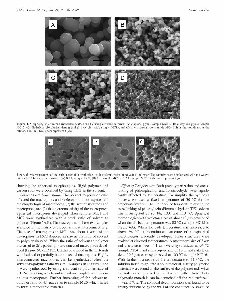
SolVent-to-Polymer Ratio. The solvent-to-polymer ratioaffected the macropores and skeletons in three aspects: (1)the morphology of macropores, (2) the size of skeletons andmacropores, and (3) the interconnectivity of the macropores.Spherical macropores developed when samples MC1 andMC2 were synthesized with a small ratio of solvent topolymer (Figure 5A,B). The macropores in these two samplesscattered in the matrix of carbon without interconnectivity.The size of macropores in MC1 was about 1 µm and themacropores in MC2 doubled in size as the ratio of solventto polymer doubled. When the ratio of solvent to polymerincreased to 2:1, partially interconnected macropores devel-oped (Figure 5C) in MC3. Cracks developed in the materialswith isolated or partially interconnected macropores. Highlyinterconnected macropores can be synthesized when thesolvent-to-polymer ratio was 3:1. Samples in Figures 3 and4 were synthesized by using a solvent-to-polymer ratio of3:1. No cracking was found in carbon samples with bicon-tinuous macropores. Further increasing of the solvent-to-polymer ratio of 4:1 gave rise to sample MC5 which failedto form a monolithic material.
Effect of Temperature. Both prepolymerization and cross-linking of phloroglucinol and formaldehyde were signifi-cantly affected by temperature. To simplify the synthesisprocess, we used a fixed temperature of 30 °C for theprepolymerization. The influence of temperature during thecross-linking of phloroglucinol/formaldehyde in TEG solventwas investigated at 80, 96, 100, and 110 °C. Sphericalmorphologies with skeleton sizes of about 10 µm developedwhen the air-bath temperature was 80 °C (sample MC15 inFigure 6A). When the bath temperature was increased toabove 96 °C, a bicontinuous structure of nonsphericalmorphologies gradually developed. Finer structures wereevolved at elevated temperatures. A macropore size of 3 µmand a skeleton size of 1 µm were synthesized at 96 °C(sample MC4), and a macropore size of 1 µm and a skeletonsize of 0.5 µm were synthesized at 100 °C (sample MC16).With further increasing of the temperature to 110 °C, thesolution failed to gel into a solid material. Fluffy polymericmaterials were found on the surface of the polymer rods whenthe rods were removed out of the air bath. These fluffypolymeric materials can be scratched off the rod surface.
Wall Effect. The spinodal decomposition was found to begreatly influenced by the wall of the container. A so-called
Figure 4. Morphologies of carbon monoliths synthesized by using different solvents: (A) ethylene glycol, sample MC11; (B) diethylene glycol, sampleMC12; (C) diethylene glycol/triethylene glycol (1:1 weight ratio), sample MC13; and (D) triethylene glycol, sample MC4 (this is the sample set as thereference recipe). Scale bars represent 5 µm.
Figure 5. Microstructures of the carbon monolith synthesized with different ratios of solvent to polymer. The samples were synthesized with the weightratios of TEG-to-polymer mixture: (A) 0.5:1, sample MC1; (B) 1:1, sample MC2; (C) 2:1, sample MC3. Scale bars represent 2 µm.
2120 Chem. Mater., Vol. 21, No. 10, 2009 Liang and Dai

“wall effect” has been studied both theoretically and experi-mentally.21 As a result of the wall effect, the sizes of domainsnear the wall differ from those away from the wall.21-23
Heterogeneity in the skeletal structures was observed at thecross section of the carbon rods. In a typical preparation asdescribed in the reference recipe for MC4, a layer of an ca.20 µm thick heterogeneous region formed as the outmostshell of the carbon rods. This heterogeneous shell wasvisualized in Figure 7A that was indicated by red lines andan arrow. The texture of the shell was finer than the rest ofthe rods. The wall effect can be eliminated by aging thepolymer rods in a pure solvent without contact of the glasstube. Sample MC18 was prepared according to the MC4reference recipe except for the aging stage, which was
conducted in TEG after the polymer rod was formed. Noheterogeneous shell was found in the carbon rods preparedfrom sample MC18 as shown in Figure 7B. The surfacetexture of carbon rods from samples MC4 and MC18 wereimaged at the same magnification and compared in parts (C)and (D), respectively, in Figure 7. Evidently; the wall effectresulted in a finer superficial grain size of MC4 than that ofMC18.
Clouding Point. The commencement of the phase separa-tion was observed when the solution became cloudy. Theturbidity of the solution was caused by the formation ofinsoluble polymer-rich domains. The time when the transpar-ency of the solution completely disappeared was recordedas a clouding point. Except for MC14 and MC17, allpreparations had a clouding point between 30 min and 6 h.We found that the clouding point was associated with thedomain size of the resulting monoliths. When the solution
(21) Torres, F. E.; Troian, S. M. Colloids Surf., A 1994, 89, 227–239.(22) Troian, S. M. Phys. ReV. Lett. 1993, 71, 1399–1402.(23) Puri, S. J. J. Phys.: Condens. Matter 2005, 17, R101–R142.
Figure 6. Microstructures of carbon monoliths synthesized at different temperatures. (A) 80 °C, sample MC15, scale bar represents 10 µm; and (B) 100 °C,sample MC16, scale bar represents 1 µm.
Figure 7. Heterogeneity induced by the wall effect: (A) Cross section of carbon monolith rod prepared according to the reference recipe, MC4. Red linesand arrows indicate the heterogeneity domain at the edge of the carbon rod. The thickness of the heterogeneity domain is about 20 µm. Scale bar represents20 µm. (B) Cross section of carbon monolith rod without wall effect, sample MC18. Scale bar represents 5 µm. (C) Surface texture of sample MC4 withwall effect. (D) Surface texture of sample MC18 without wall effect. Scale bars in (C) and (D) represent 10 µm.
2121Chem. Mater., Vol. 21, No. 10, 2009Bimodal Meso-/Macroporous Carbon Monoliths

clouded within a short period in the air bath, coarse domainswith spherical morphologies developed. For example, MC6,MC11, and MC12 had clouding points of 30 min, 1 h, and2 h; all three samples had spherical morphologies with grainsizes of 20, 5, and 2 µm. When the clouding point occurredafter 3 h, the morphologies of the resulting monoliths werebicontinuous structures with fine domains. Finer structureswere resulting from higher air-bath temperature or longerprepolymerization time. Phenomenologically, the formationof fine bicontinuous monolith was always accompanied bya long clouding point. MC10 and MC16 were preparedaccording to the recipe of MC4 with longer prepolymeriza-tion time and higher air-bath temperature. The correspondingclouding points of MC10 and MC16 were 6 and 5 h,respectively. Compared with the 3.5 h of MC4, the cloudingpoints of MC10 and MC16 occurred much later. The domainsizes of MC10 and MC16 were much finer than those ofMC4. The characteristics of domain sizes were detailed inTable 2. The textures of samples MC4, MC10, and MC16were visualized in Figures 3D, 3F, and 6B.
Mesopore and Heating Treatment. Apart from varioussizes and morphologies of macropores, all carbon rods hada uniform mesopore size distribution around 8 nm. Themesopores rendered high surface areas to these carbon rods(about 350 m2/g). The pore volumes at 0.95 P/P0 were about0.45 cm3/g. Sample MC18 had a slightly higher surface areaand pore volume than other samples. This observation couldbe attributed to the elimination of the wall effect. The detailedcharacteristics of the mesopores were tabulated in Table 3.The carbon resulting from MC4 was further heated to 2600°C. No obvious dimensional change was found except forthe mesopores that were slightly shrunk from 8 to 6.5 nm.The high-temperature heating treatment resulted in graphiticstructures as shown in the PXRD patterns in Figure 8. Thecarbon prepared at 850 °C had two broad diffraction peaksat 2θ of 24.5° and 43.2°. Such a PXRD pattern indicatedthat the carbon made at 850 °C was an amorphous carbon.The sample heat-treated to 2600 °C showed distinguishedgraphitic carbon characteristics with a sharp peak at 2θ of26° and three differentiable peaks at high 2θ angles thatrevealed a highly crystalline structure.
Discussion
The formation of macropores through spinodal decompo-sition was studied in many polymeric and inorganic
systems.8,14,24,25 The bicontinuous appearance of microstruc-tures in the resulting carbon certainly suggested a spinodaldecomposition mechanism. The uniform mesopores wereindependent of the composition, temperature, and polymer-ization history. The size and uniformity of the mesoporesstrongly suggested that the mesopores were formed by a soft-template approach1,20,26-28 in which the triblock copolymerformed a micelle structure with the phloroglucinol/formal-dehyude resin through hydrogen bonding.20,26 The underpin-ning physics of soft-template approach is the microphaseseparation. Thus, all of these results can be reconciled witha model in which two phase separations, i.e., microphaseseparation and spinodal decomposition, occurred concurrentlyin a single system. We denoted the coupling of microphaseseparation with spinodal decomposition as “dual phaseseparation”. As illustrated in Scheme 1, in a dual phaseseparation system, the macropores and carbon skeletons wereformed through spinodal decomposition and the mesoporeswere formed by microphase separation. A similar dual phaseseparation system with mixtures of organic and inorganicspecies was studied extensively by Nakanishi and Tanakafor the preparation of bimodal porous oxides.5 The Nakanishiapproach employed a sol-gel process for the preparation ofmesopores, which was an inorganic polymerization system,while the system investigated in this paper was a distinctall-organic system.
When phloroglucinol was mixed with triblock copolymerof PEO-PPO-PEO, phloroglucinol preferentially concen-trated in the PEO domain of the block copolymer throughhydrogen bonding. This mixture underwent microphaseseparation in selective solvents. As a result of the microphaseseparation, the PPO segments, which were the minorcomponent in the mixture, aggregated and formed the coresof the micelles. The PEO domain incorporated with phlo-
(24) Hashimoto, T.; Takenaka, M.; Jinnai, H. Polym. Commun. 1989, 30,177–179.
(25) Nakanishi, K. J. Porous Mater. 1997, 4, 67–112.(26) Liang, C. D.; Hong, K. L.; Guiochon, G. A.; Mays, J. W.; Dai, S.
Angew. Chem., Int. Ed. 2004, 43, 5785–5789.(27) Meng, Y.; Gu, D.; Zhang, F. Q.; Shi, Y. F.; Yang, H. F.; Li, Z.; Yu,
C. Z.; Tu, B.; Zhao, D. Y. Angew. Chem., Int. Ed. 2005, 44, 7053–7059.
(28) Zhang, F. Q.; Meng, Y.; Gu, D.; Yan, Y.; Yu, C. Z.; Tu, B.; Zhao,D. Y. J. Am. Chem. Soc. 2005, 127, 13508–13509.
Table 3. Characteristics of Mesopores
sample ID surface area (m2/g) pore size (nm) pore volume (cm3/g)
MC3 331.6 8.0 0.41MC4 349.5 8.0 0.45MC6 347.2 8.1 0.44MC7 361.2 8.3 0.43MC8 323.4 7.8 0.41MC9 345.8 8.1 0.44MC10 331.3 7.8 0.43MC11 337.1 7.9 0.45MC12 351.6 8.0 0.44MC13 348.9 8.1 0.43MC15 344.7 8.1 0.43MC16 338.4 8.0 0.45MC18 420.3 8.5 0.56
Figure 8. Powder X-ray diffraction patterns of a bimodal porous carbonheated at 850 °C (black solid line) and 2600 °C (red dashed line).
2122 Chem. Mater., Vol. 21, No. 10, 2009 Liang and Dai

roglucinol and formed the matrix as the dominant componentin the mixture. In the prepolymerization step, formaldehydecopolymerized with phloroglucinol and formed oligomers.The solubility of the polymer mixture in the alcoholicsolution significantly decreased when phloroglucinol/form-aldehyde (PF) oligomers formed. Thus, the polymer phaseseparated from the alcoholic solvents. Microphase separationoccurred in the polymer phase that separated from theprepolymerization. This prepolymerization process is crucialfor simplifying the synthesis system as we noticed that theblock copolymer is sparely soluble in the glycolic solvent.Therefore, it is difficult to achieve a homogeneous solutionwith direct mixing of block copolymers and phloroglocinolin the glycolic solvent. The polymer mixtures from theprepolymerized PF oligomers and PEO-PPO-PEO aremiscible with the glycolic solvents. Apparently, the PFoligomers promoted the solubility of PEO-PPO-PEO inglycolic solvents with an unknown mechanism. Formalde-hyde was provided as an aqueous solution. The prepolymer-ization resulted in a homogeneous mixture of PEO-PPO-PEO and PF oligomers. This mixture was insoluble in water;therefore, water was excluded in the synthesis system. Watercontent in the solvents could greatly influence the spinodaldecomposition.14 The prepolymerization excluded the use ofwater and consequently simplified the solvents system.Miscibility of the polymer mixture with the glycolic solventshad a strong dependence on the molecular weights of thePF oligomers. Although we did not check the averagemolecular weights of the prepolymerized mixtures, we foundthat the duration of prepolymerization distinctly affected thespinodal decomposition.
After the single-phase mixture of P/F oligomers, PEO-PPO-PEO, and glycolic solvents was heated in the air bath,immiscibility progressively developed with concomitantpolymerization. This process is known as polymerization-induced phase separation. Depending on the nature of thesystem, the phase separation could develop from spinodaldecomposition or binodal decomposition.8The binodal de-composition resulted in isolated spherical domains. Mostlikely, the isolated spherical pores in samples MC1 and MC2and discrete spherical particles in MC15 resulted from abinodal decomposition process. Bicontinuous microstructures
of MC4, MC7, MC8, MC9, MC10, and MC16 ambiguouslydeveloped from the spinodal decomposition. Bicontinuousmicrostructures with spherelike or fused microspheres as seenin MC12 and MC13 could be the result of the boundary ofspinodal and binodal phase separations. Miscibility is a majorparameter governing the spinodal decomposition as wenoticed that the immiscibility of the mixture occurred whenthe clouding point appeared. From the time when theclouding point appeared, the single-phase mixture developedinto two phases: a solvent-rich phase and polymer-rich phase.These two phases gradually developed with the progress ofpolymerization. These results showed that the microstructuresof the carbon were correlated with the clouding point.Preparations with long clouding points resulted in finemicrostructures. The later the clouding points occurred, thelonger the miscibility of the single-phase mixture wasmaintained. Evidently, the scale of domains depended onthe miscibility of the mixture. The temperature of the airbath affected the spinodal decomposition through two factors:increased miscibility at higher temperature and increasedpolymerization rate of the PF oligomers. The increase ofclouding points in MC15, MC4, and MC16 elucidated thatthe polymers and the glycolic solvents had high miscibilityat elevated temperature. The scale of the microstructuresdecreased at high temperature. When the temperature wasabove 110 °C (sample MC17), immiscibility did not developwithin 12 h. Therefore, no spinodal decomposition wasobserved in the investigated conditions. Secondary phaseseparation within the primary phase was observed in MC7.Secondary phase separation is a common phenomenonoccurring in spinodal decomposition systems when themiscibility of the system is affected by other minor solvents.14
With a short prepolymerization step, the polymer mixtureseparated from the ethanolic solution contained higherconcentrations of water and ethanol than those polymersprepared after a long prepolymerization time. In the case of
Scheme 1. Schematic Illustration of Bimodal Porous CarbonResulting from Dual Phase Separation
Figure 9. Photograph of three carbon monolithic rods; the HPLC columnon the left side is for the purpose of showing the size of the rods.
2123Chem. Mater., Vol. 21, No. 10, 2009Bimodal Meso-/Macroporous Carbon Monoliths

MC7, the prepolymerized polymer was prepared within 30min; therefore, water or ethanol dissolved in the prepoly-merized polymer could be the minor solvents that causedthe secondary phase separation.
The growth of domains in spinodal decomposition wassignificantly affected by an interface, which preferentiallyattracted one of the two domains. This effect was known inthe literature as “wall effect”.21,22 We found that the walleffect could be avoided by aging the phase-separated mixturein a pure glycolic solvent without contacting the container.Therefore, in our system, the wall effect did not develop inthe earlier stage of the spinodal decomposition.
All carbon materials with bicontinuous microstructureswere rigid structures. Shown in Figure 9 is a photo of threecarbon monolithic rods synthesized inside glass tubes with7 cm i.d. and length of 20 cm. The U.S. quarter coin on theright side of the photo is employed to demonstrate the sizeof the carbon rods. The shiny surface of the carbon rods isas smooth as a mirror. We did not observe cracks duringthe handling, drying, and carbonization of the polymer rods.Heating treatment up to 2600 °C deteriorated neither themacropores nor the mesopores.
Conclusions
Bimodal porous carbon monoliths were synthesized througha dual phase separation process in which microphase
separation occurred in the polymer phase and spinodaldecomposition progressively developed through the cross-linking of the corresponding polymer mixture. As a resultof this dual phase separation, macropores evolved from thesolvent-rich phase and the mesopores were rendered afterthe pyrolysis of block copolymer templates. The sizes of themacropores and skeletons varied with reaction temperatures,prepolymerization times, and solvent compositions, whereasthe mesopores tended to be independent of the spinodaldecomposition process. This dual phase separation processoffers a versatile method for the synthesis of bimodal porouscarbon materials with tunability in two discrete length scaleswithout interactive influences. Stable rigid structures wereobtained even after treatment at extremely high temperature.
Acknowledgment. This research was sponsored by theDivision of Chemical Sciences, Office of Basic Energy Sciences,U.S. Department of Energy under Contract DE-AC05-00OR22725with Oak Ridge National Laboratory, managed and operatedby UT-Battelle, LLC. The electron microscopic images weretaken at the Center for Nanophase Materials Sciences, whichis sponsored at Oak Ridge National Laboratory by the ScientificUser Facilities Division, Office of Basic Energy Sciences, U.S.Department of Energy.
CM900344H
2124 Chem. Mater., Vol. 21, No. 10, 2009 Liang and Dai