dtx series
TRANSCRIPT
DTX Series CableAnalyzerTM
Technical Reference Handbook
April 2004, Rev. 3 3/06 © 2004, 2006 Fluke Corporation. All rights reserved. All product names are trademarks of their respective companies.

LIMITED WARRANTY AND LIMITATION OF LIABILITY Each Fluke Networks product is warranted to be free from defects in material and workmanship under normal use and service. The warranty period for the mainframe is one year and begins on the date of purchase. Parts, accessories, product repairs and services are warranted for 90 days, unless otherwise stated. Ni-Cad, Ni-MH and Li-Ion batteries, cables or other peripherals are all considered parts or accessories. The warranty extends only to the original buyer or end user customer of a Fluke Networks authorized reseller, and does not apply to any prod-uct which, in Fluke Networks’ opinion, has been misused, abused, altered, neglected, contaminated, or damaged by accident or abnormal conditions of operation or handling. Fluke Networks warrants that software will operate substantially in accordance with its functional specifications for 90 days and that it has been properly recorded on non-defective media. Fluke Networks does not warrant that software will be error free or operate without interruption. Fluke Networks authorized resellers shall extend this warranty on new and unused products to end-user customers only but have no author-ity to extend a greater or different warranty on behalf of Fluke Networks. Warranty support is available only if product is purchased through a Fluke Networks authorized sales outlet or Buyer has paid the applicable international price. Fluke Networks reserves the right to invoice Buyer for importation costs of repair/replacement parts when product purchased in one country is submitted for repair in another country. Fluke Networks' warranty obligation is limited, at Fluke Networks' option, to refund of the purchase price, free of charge repair, or replace-ment of a defective product which is returned to a Fluke Networks authorized service center within the warranty period. To obtain warranty service, contact your nearest Fluke Networks authorized service center to obtain return authorization information, then send the product to that service center, with a description of the difficulty, postage and insurance prepaid (FOB Destination). Fluke Net-works assumes no risk for damage in transit. Following warranty repair, the product will be returned to Buyer, transportation prepaid (FOB Destination). If Fluke Networks determines that failure was caused by neglect, misuse, contamination, alteration, accident or abnormal condition of operation or handling, or normal wear and tear of mechanical components, Fluke Networks will provide an estimate of repair costs and obtain authorization before commencing the work. Following repair, the product will be returned to the Buyer transportation prepaid and the Buyer will be billed for the repair and return transportation charges (FOB Shipping Point). THIS WARRANTY IS BUYER'S SOLE AND EXCLUSIVE REMEDY AND IS IN LIEU OF ALL OTHER WARRANTIES, EXPRESS OR IMPLIED, INCLUDING BUT NOT LIMITED TO ANY IMPLIED WARRANTY OF MERCHANTABILITY OR FITNESS FOR A PARTICULAR PURPOSE. FLUKE NETWORKS SHALL NOT BE LIABLE FOR ANY SPECIAL, INDIRECT, INCIDENTAL OR CONSEQUENTIAL DAMAGES OR LOSSES, INCLUDING LOSS OF DATA, ARISING FROM ANY CAUSE OR THEORY. Since some countries or states do not allow limitation of the term of an implied warranty, or exclusion or limitation of incidental or conse-quential damages, the limitations and exclusions of this warranty may not apply to every buyer. If any provision of this Warranty is held invalid or unenforceable by a court or other decision-maker of competent jurisdiction, such holding will not affect the validity or enforce-ability of any other provision. 4/04
Fluke Networks PO Box 777 Everett, WA 98206-0777 USA
i
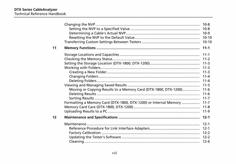
Table of Contents
Chapter Title Page
1 Getting Acquainted ...................................................................................................... 1-1
Overview of Features.................................................................................................... 1-1 Registration................................................................................................................... 1-2 Contacting Fluke Networks .......................................................................................... 1-2 Additional Resources for Cable Testing Information.................................................. 1-3 Unpacking ..................................................................................................................... 1-3
DTX-1800 .................................................................................................................. 1-3 DTX-1200 .................................................................................................................. 1-4 DTX-LT ...................................................................................................................... 1-4 DTX-MFM2 Multimode Fiber Modules (optional) .................................................. 1-5 DTX-GFM2 Multimode Fiber Modules (optional) ................................................... 1-5 DTX-SFM2 Singlemode Fiber Modules (optional)................................................... 1-5
Safety Information........................................................................................................ 1-6 Basic Features ................................................................................................................ 1-8
Physical Features ...................................................................................................... 1-8 Changing the Language .......................................................................................... 1-14 Powering the Tester................................................................................................. 1-14
DTX Series CableAnalyzer Technical Reference Handbook
ii
About Link Interface Adapters and Modules......................................................... 1-18 Verifying Operation................................................................................................. 1-21 Checking the Hardware and Software Versions .................................................... 1-22 The Main Autotest Screen....................................................................................... 1-22
Setting User Preferences .............................................................................................. 1-24 Changing the Date, Time, and Date/Time Formats................................................ 1-24 Changing the Length Units ..................................................................................... 1-24 Changing the Numeric Format ............................................................................... 1-24 Adjusting the Display Contrast ............................................................................... 1-25 Setting the Power Down Timer .............................................................................. 1-25 Setting the Backlight Timer .................................................................................... 1-25 Enabling or Disabling the Beeper ........................................................................... 1-26
Overview of Memory Features .................................................................................... 1-26 Inserting and Removing the Memory Card ............................................................ 1-26 Formatting the Memory Card (DTX-1800 and DTX-1200) or Internal Memory... 1-26 Creating Folders....................................................................................................... 1-27 Setting the Storage Location (DTX-1800 and DTX-1200) ..................................... 1-28 Options for Entering Cable IDs ............................................................................... 1-28
Using the Talk Mode .................................................................................................... 1-30 About LinkWare and LinkWare Stats Software .......................................................... 1-30
2 Tutorials on Setup and Test Procedures ..................................................................... 2-1 Preparing to Save Tests ................................................................................................ 2-1
Step 1: Checking the Memory Space Available...................................................... 2-1 Step 2: Entering Job Information............................................................................ 2-2 Step 3: Setting the Storage Location (DTX-1800 and DTX-1200) .......................... 2-4 Step 4: Setting Up a Job Folder............................................................................... 2-4 Step 5: Selecting a Cable ID Source......................................................................... 2-5
Contents (continued)
iii
Certifying Twisted Pair Cabling.................................................................................... 2-5 Required Equipment ................................................................................................ 2-6 Step 1: Checking the Battery Status and Verifying Operation with Twisted Pair Adapters ............................................................................................................ 2-7 Step 2: Selecting a Test Limit, Cable Type, and Outlet Configuration .................. 2-8 Step 3: Running the Autotest .................................................................................. 2-8 Step 4: Viewing the Autotest Results...................................................................... 2-11 Step 5: Saving the Results ........................................................................................ 2-12
Certifying Fiber Cabling................................................................................................ 2-12 Required Equipment ................................................................................................ 2-12 Step 1: Installing the Fiber Modules........................................................................ 2-14 Step 2: Checking the Battery Status and Verifying Operation with Fiber Modules .................................................................................................................... 2-14 Step 3: Selecting a Fiber Type and Test Limit ......................................................... 2-15 Step 4: Configuring the Fiber Test .......................................................................... 2-16 Step 5: Setting the Reference .................................................................................. 2-16 Step 6: Running the Test.......................................................................................... 2-18 Step 7: Viewing the Results ..................................................................................... 2-19 Step 8: Saving the Results ........................................................................................ 2-19
Using the Auto Increment and Sequential Cable ID Features .................................... 2-20 Using the Auto Increment Feature.......................................................................... 2-20 Creating a List of Sequential IDs ............................................................................. 2-21 About ANSI/TIA/EIA-606-A Cable IDs....................................................................... 2-24
3 Certifying Twisted Pair Cabling ................................................................................... 3-1 Setting the Reference ................................................................................................... 3-1 Testing Twisted Pair Patch Cords ................................................................................. 3-2 Twisted Pair Test Settings............................................................................................. 3-3
DTX Series CableAnalyzer Technical Reference Handbook
iv
Autotest on Twisted Pair Cabling................................................................................ 3-6 Twisted Pair Autotest Results ...................................................................................... 3-9
Automatic Diagnostics............................................................................................. 3-11 PASS*/FAIL* Results ................................................................................................. 3-12 Wire Map ................................................................................................................. 3-13 Resistance................................................................................................................. 3-15 Characteristic Impedance ........................................................................................ 3-15 Length ...................................................................................................................... 3-16 Propagation Delay and Delay Skew........................................................................ 3-17 Insertion Loss ........................................................................................................... 3-18 NEXT (Near-End Crosstalk) ...................................................................................... 3-20 ACR (Attenuation to Crosstalk Ratio) ..................................................................... 3-22 Return Loss............................................................................................................... 3-24 PSNEXT (Power Sum Near End Crosstalk) Test ....................................................... 3-26 PSACR (Power Sum Attenuation to Crosstalk Ratio) Test...................................... 3-26 ELFEXT (Equal Level Far-End Crosstalk) Test .......................................................... 3-26 PSELFEXT Test .......................................................................................................... 3-29
Running Single Tests .................................................................................................... 3-29 Monitoring Impulse Noise............................................................................................ 3-31 Using the Tone Generator ........................................................................................... 3-34
4 Certifying Coaxial Cabling ........................................................................................... 4-1 Setting the Reference................................................................................................... 4-1 Coaxial Test Settings..................................................................................................... 4-3 Autotest on Coaxial Cabling ........................................................................................ 4-5 Coaxial Autotest Results............................................................................................... 4-9
HDTDR Analyzer ...................................................................................................... 4-10 Resistance................................................................................................................. 4-10
Contents (continued)
v
Impedance ................................................................................................................ 4-10 Length....................................................................................................................... 4-11 Propagation Delay ................................................................................................... 4-11 Insertion Loss ............................................................................................................ 4-11
Running Single Tests..................................................................................................... 4-11 5 Diagnosing Copper Cabling Faults .............................................................................. 5-1
Using the Automatic Diagnostics ................................................................................. 5-1 Avoiding Tester-Induced Failures................................................................................. 5-1 Common Causes of Copper Cabling Failures............................................................... 5-2 The HDTDX Analyzer .................................................................................................... 5-9
Running the HDTDX Analyzer ................................................................................. 5-9 Recognizing Faults on HDTDX Plots........................................................................ 5-11
The HDTDR Analyzer .................................................................................................... 5-12 Running the HDTDR Analyzer ................................................................................. 5-12 Recognizing Faults on HDTDR Plots ........................................................................ 5-12
6 Certifying Fiber Optic Cabling...................................................................................... 6-1 Overview of Features.................................................................................................... 6-1 Safety Information........................................................................................................ 6-2 Installing and Removing Fiber Modules ...................................................................... 6-4 Installing the Connector Adapter ................................................................................ 6-6 Verifying Operation...................................................................................................... 6-8 Essentials for Reliable Fiber Test Results...................................................................... 6-8
Cleaning Connectors and Adapters......................................................................... 6-8 About Setting the Reference................................................................................... 6-10 Selecting Reference Test Cords................................................................................ 6-11 Testing Your Reference Test Cords ......................................................................... 6-11
DTX Series CableAnalyzer Technical Reference Handbook
vi
Using Mandrels for Testing Multimode Fiber ........................................................ 6-12 Fiber Test Settings ........................................................................................................ 6-14 About Method B Connections ..................................................................................... 6-18 Autotest in Smart Remote Mode................................................................................. 6-19
Setting the Reference for Smart Remote Mode .................................................... 6-20 Running the Autotest in Smart Remote Mode ...................................................... 6-22 Smart Remote Mode Autotest Results.................................................................... 6-24
Autotest in Loopback Mode ........................................................................................ 6-26 Setting the Reference in Loopback Mode.............................................................. 6-28 Running the Autotest in Loopback Mode.............................................................. 6-30 Loopback Mode Autotest Results ........................................................................... 6-32
Autotest in Far End Source Mode................................................................................ 6-34 Setting the Reference in Far End Source Mode ..................................................... 6-36 Running the Autotest in Far End Source Mode ..................................................... 6-38 Far End Source Mode Autotest Results................................................................... 6-40
Bi-Directional Testing................................................................................................... 6-42 Bi-Directional Results for Smart Remote Mode ..................................................... 6-42 Bi-Directional Results for Loopback Mode ............................................................. 6-42
Finding Connections with FindFiber............................................................................ 6-44 Using FindFiber in Smart Remote Mode................................................................. 6-44 Using FindFiber in Loopback Mode ........................................................................ 6-48
Using the Power Meter ................................................................................................ 6-50 Running Single Tests .................................................................................................... 6-54 Using the Remote Tester with an OptiFiber Tester ................................................. 6-54
7 Locating Fibers and Faults with the Visual Fault Locator .......................................... 7-1 Visual Fault Locator Applications ................................................................................ 7-1 Using the Visual Fault Locator ..................................................................................... 7-2
Contents (continued)
vii
8 Diagnosing Fiber Cabling Faults .................................................................................. 8-1 Common Causes of Failures.......................................................................................... 8-1 Diagnosing Failures....................................................................................................... 8-2
9 Verifying Network Service ........................................................................................... 9-1 Overview of Features.................................................................................................... 9-1 Software Requirements ................................................................................................ 9-1 Installing and Removing the Network Module and Optional SFP Module ............... 9-2 Verifying Network Connectivity................................................................................... 9-4
Network Connectivity Test Settings ........................................................................ 9-4 Entering Ping Addresses .......................................................................................... 9-5 Running the Connectivity Test ................................................................................ 9-6 Saving Connectivity Results ..................................................................................... 9-6
Pinging Network Devices.............................................................................................. 9-11 Monitoring Network Traffic ......................................................................................... 9-12 Blinking a Port Light ..................................................................................................... 9-14 Identifying Links (twisted pair only) ............................................................................ 9-14 Diagnosing Low-Level Network Problems................................................................... 9-16
10 Custom Test Settings.................................................................................................... 10-1 Creating a Custom Twisted Pair Cable Type................................................................ 10-1 Creating a Custom Fiber Type ...................................................................................... 10-3 Creating a Custom Twisted Pair Test Limit .................................................................. 10-4 Creating a Custom Fiber Limit...................................................................................... 10-5 Creating a Custom Outlet Configuration .................................................................... 10-6 Editing Custom Settings ............................................................................................... 10-7 Deleting Custom Settings ............................................................................................. 10-7
DTX Series CableAnalyzer Technical Reference Handbook
viii
Changing the NVP ........................................................................................................ 10-8 Setting the NVP to a Specified Value ..................................................................... 10-8 Determining a Cable's Actual NVP.......................................................................... 10-9 Resetting the NVP to the Default Value................................................................. 10-10
Transferring Custom Settings Between Testers .......................................................... 10-10 11 Memory Functions ....................................................................................................... 11-1
Storage Locations and Capacities ................................................................................ 11-1 Checking the Memory Status....................................................................................... 11-2 Setting the Storage Location (DTX-1800, DTX-1200).................................................. 11-3 Working with Folders................................................................................................... 11-3
Creating a New Folder............................................................................................. 11-3 Changing Folders ..................................................................................................... 11-4 Deleting Folders....................................................................................................... 11-4
Viewing and Managing Saved Results ........................................................................ 11-5 Moving or Copying Results to a Memory Card (DTX-1800, DTX-1200)................. 11-6 Deleting Results ....................................................................................................... 11-6 Sorting Results ......................................................................................................... 11-7
Formatting a Memory Card (DTX-1800, DTX-1200) or Internal Memory .................. 11-7 Memory Card Care (DTX-1800, DTX-1200) .................................................................. 11-8 Uploading Results to a PC ............................................................................................ 11-9
12 Maintenance and Specifications ................................................................................. 12-1 Maintenance................................................................................................................. 12-1
Reference Procedure for Link Interface Adapters.................................................. 12-1 Factory Calibration .................................................................................................. 12-2 Updating the Tester’s Software .............................................................................. 12-2 Cleaning ................................................................................................................... 12-6
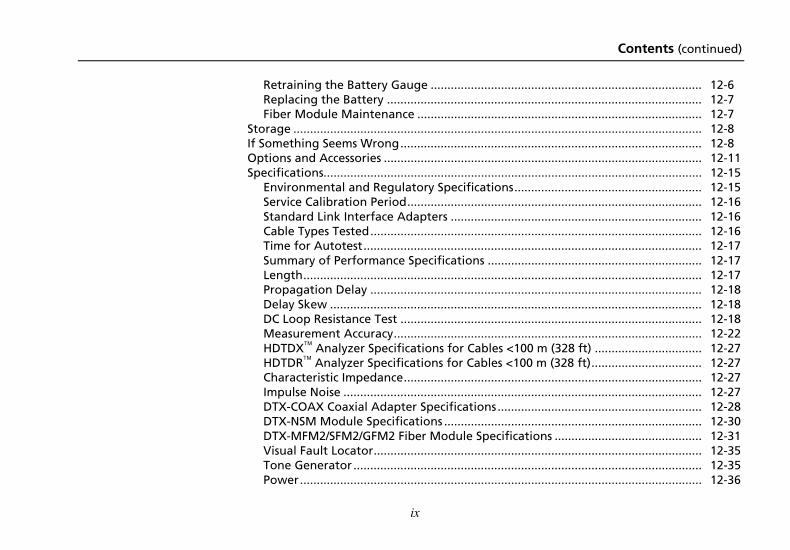
Contents (continued)
ix
Retraining the Battery Gauge ................................................................................. 12-6 Replacing the Battery .............................................................................................. 12-7 Fiber Module Maintenance ..................................................................................... 12-7
Storage .......................................................................................................................... 12-8 If Something Seems Wrong.......................................................................................... 12-8 Options and Accessories ............................................................................................... 12-11 Specifications................................................................................................................. 12-15
Environmental and Regulatory Specifications........................................................ 12-15 Service Calibration Period........................................................................................ 12-16 Standard Link Interface Adapters ........................................................................... 12-16 Cable Types Tested................................................................................................... 12-16 Time for Autotest..................................................................................................... 12-17 Summary of Performance Specifications ................................................................ 12-17 Length....................................................................................................................... 12-17 Propagation Delay ................................................................................................... 12-18 Delay Skew ............................................................................................................... 12-18 DC Loop Resistance Test .......................................................................................... 12-18 Measurement Accuracy............................................................................................ 12-22 HDTDX Analyzer Specifications for Cables <100 m (328 ft) ................................ 12-27 HDTDR Analyzer Specifications for Cables <100 m (328 ft)................................. 12-27 Characteristic Impedance......................................................................................... 12-27 Impulse Noise ........................................................................................................... 12-27 DTX-COAX Coaxial Adapter Specifications............................................................. 12-28 DTX-NSM Module Specifications ............................................................................. 12-30 DTX-MFM2/SFM2/GFM2 Fiber Module Specifications ............................................ 12-31 Visual Fault Locator.................................................................................................. 12-35 Tone Generator ........................................................................................................ 12-35 Power........................................................................................................................ 12-36
DTX Series CableAnalyzer Technical Reference Handbook
x
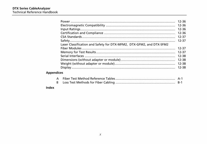
Power ....................................................................................................................... 12-36 Electromagnetic Compatibility ............................................................................... 12-36 Input Ratings............................................................................................................ 12-36 Certification and Compliance ................................................................................. 12-36 CSA Standards.......................................................................................................... 12-37 Safety........................................................................................................................ 12-37 Laser Classification and Safety for DTX-MFM2, DTX-GFM2, and DTX-SFM2 Fiber Modules .......................................................................................................... 12-37 Memory for Test Results.......................................................................................... 12-37 Serial Interfaces ....................................................................................................... 12-38 Dimensions (without adapter or module).............................................................. 12-38 Weight (without adapter or module)..................................................................... 12-38 Display ...................................................................................................................... 12-38
Appendices
A Fiber Test Method Reference Tables .................................................................... A-1 B Loss Test Methods for Fiber Cabling .................................................................... B-1
Index
xi
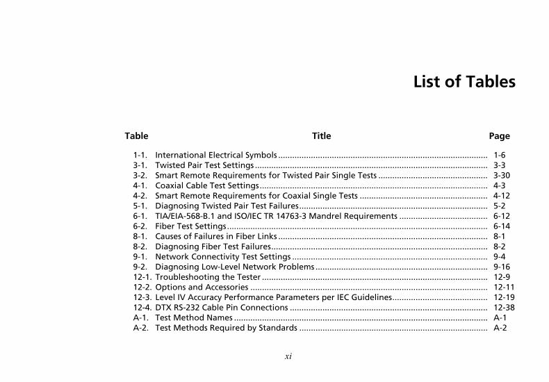
List of Tables
Table Title Page
1-1. International Electrical Symbols .......................................................................................... 1-6 3-1. Twisted Pair Test Settings .................................................................................................... 3-3 3-2. Smart Remote Requirements for Twisted Pair Single Tests ............................................... 3-30 4-1. Coaxial Cable Test Settings.................................................................................................. 4-3 4-2. Smart Remote Requirements for Coaxial Single Tests ....................................................... 4-12 5-1. Diagnosing Twisted Pair Test Failures................................................................................. 5-2 6-1. TIA/EIA-568-B.1 and ISO/IEC TR 14763-3 Mandrel Requirements ...................................... 6-12 6-2. Fiber Test Settings................................................................................................................ 6-14 8-1. Causes of Failures in Fiber Links .......................................................................................... 8-1 8-2. Diagnosing Fiber Test Failures............................................................................................. 8-2 9-1. Network Connectivity Test Settings .................................................................................... 9-4 9-2. Diagnosing Low-Level Network Problems .......................................................................... 9-16 12-1. Troubleshooting the Tester ................................................................................................. 12-9 12-2. Options and Accessories ...................................................................................................... 12-11 12-3. Level IV Accuracy Performance Parameters per IEC Guidelines......................................... 12-19 12-4. DTX RS-232 Cable Pin Connections ..................................................................................... 12-38 A-1. Test Method Names ............................................................................................................. A-1 A-2. Test Methods Required by Standards ................................................................................. A-2

DTX Series CableAnalyzer Technical Reference Handbook
xii
xiii
List of Figures
Figure Title Page
1-1. Tester Front Panel Features ................................................................................................. 1-8 1-2. Tester Side and Top Panel Features .................................................................................... 1-10 1-3. Smart Remote Features........................................................................................................ 1-12 1-4. Charging and Removing the Battery .................................................................................. 1-15 1-5. Checking the Battery Status ................................................................................................ 1-17 1-6. Attaching and Removing Adapters..................................................................................... 1-18 1-7. Handling Guidelines for Permanent Link Adapters ........................................................... 1-19 1-8. Changing the Personality Module....................................................................................... 1-20 1-9. Self Test Connections ........................................................................................................... 1-21 1-10. The Main Autotest Screen (for Twisted Pair Media) .......................................................... 1-23 1-11. Inserting and Removing the Memory Card ........................................................................ 1-27 2-1. Using the Text Editing Screen ............................................................................................. 2-3 2-2. Equipment for Certifying Twisted Pair Cabling.................................................................. 2-6 2-3. Battery Status and Self Test Connections for Twisted Pair Adapters ................................ 2-7 2-4. Permanent Link Test Connections....................................................................................... 2-9 2-5. Channel Test Connections ................................................................................................... 2-10 2-6. Autotest Summary and Diagnostic Screens ........................................................................ 2-11
DTX Series CableAnalyzer Technical Reference Handbook
xiv
2-7. Equipment for Testing in Smart Remote Mode (Method B) ............................................. 2-13 2-8. Installing Fiber Modules ...................................................................................................... 2-14 2-9. Self Test Connections for Fiber Modules............................................................................ 2-15 2-10. Smart Remote Mode Reference Connections (Method B)................................................. 2-17 2-11. Smart Remote Mode Test Connections (Method B) .......................................................... 2-18 2-12. Summary Results Screen for an Autotest on Fiber............................................................. 2-19 3-1. Twisted Pair Reference Connections .................................................................................. 3-2 3-2. Equipment for Certifying Twisted Pair Cabling ................................................................. 3-6 3-3. Permanent Link Test Connections ...................................................................................... 3-7 3-4. Channel Test Connections................................................................................................... 3-8 3-5. Autotest Summary Screen for Twisted Pair Cabling .......................................................... 3-10 3-6. Examples of Automatic Diagnostic Screens........................................................................ 3-11 3-7. PASS* and FAIL* Results...................................................................................................... 3-12 3-8. Wire Map Examples............................................................................................................. 3-13 3-9. Resistance Results ................................................................................................................ 3-15 3-10. Length Results...................................................................................................................... 3-16 3-11. Propagation Delay and Delay Skew Results ....................................................................... 3-17 3-12. Insertion Loss is a Decrease in Signal Strength .................................................................. 3-18 3-13. Insertion Loss Plot................................................................................................................ 3-19 3-14. Near-End Crosstalk (NEXT) .................................................................................................. 3-20 3-15. NEXT Plot ............................................................................................................................. 3-21 3-16. Attenuation to Crosstalk Ratio (ACR)................................................................................. 3-22 3-17. ACR Plot ............................................................................................................................... 3-23 3-18. Sources of Return Loss......................................................................................................... 3-24 3-19. Return Loss Plot ................................................................................................................... 3-25 3-20. Far-End Crosstalk (FEXT)...................................................................................................... 3-27 3-21. ELFEXT Plot .......................................................................................................................... 3-28 3-22. Causes and Effects of Noise................................................................................................. 3-31
Contents (continued)
xv
3-23. Impulse Noise Test Results ................................................................................................... 3-33 3-24. Using the Tone Generator ................................................................................................... 3-35 4-1. Coaxial Reference Connections ........................................................................................... 4-2 4-2. Equipment for Certifying Coaxial Cabling.......................................................................... 4-5 4-3. Coaxial Network Cabling Test Connections........................................................................ 4-7 4-4. Coaxial Video Cabling Test Connections............................................................................. 4-8 4-5. Autotest Results for Coaxial Cabling................................................................................... 4-9 5-1. HDTDX Plot (permanent link adapters used) ..................................................................... 5-10 5-2. Interpreting HDTDX Plots .................................................................................................... 5-11 5-3. HDTDR Plot (permanent link adapters used)...................................................................... 5-13 5-4. Interpreting HDTDR Plots .................................................................................................... 5-14 6-1. Installing and Removing Fiber Modules ............................................................................. 6-4 6-2. Fiber Module Features ......................................................................................................... 6-5 6-3. SC, ST, LC, and FC Connector Adapters ............................................................................... 6-6 6-4. Installing the Connector Adapter ....................................................................................... 6-7 6-5. Self Test Connections for Fiber Modules ............................................................................ 6-8 6-6. Wrapping a Reference Test Cord Around a Mandrel......................................................... 6-13 6-7. Example of Hawe to Determine the Number of Adapters ................................................ 6-16 6-8. Equipment for Testing in Smart Remote Mode (Method B).............................................. 6-19 6-9. Smart Remote Mode Reference Connections (Method B) ................................................. 6-21 6-10. Smart Remote Mode Test Connections (Method B) ........................................................... 6-23 6-11. Smart Remote Mode Summary and Loss Result Screens (unsaved, single-directional) .... 6-24 6-12. Equipment for Testing in Loopback Mode (Method B) ..................................................... 6-27 6-13. Loopback Mode Reference Connections (Method B)......................................................... 6-29 6-14. Loopback Mode Test Connections (Method B) .................................................................. 6-31 6-15. Loopback Mode Summary and Loss Results Screens (single-directional) .......................... 6-32 6-16. Equipment for Testing in Far End Source Mode (Method B)............................................. 6-35 6-17. Far End Source Mode Reference Connections (Method B) ................................................ 6-37
DTX Series CableAnalyzer Technical Reference Handbook
xvi
6-18. Far End Source Mode Test Connections (Method B) ......................................................... 6-39 6-19. Far End Source Mode Summary and Results Screens......................................................... 6-40 6-20. Unsaved and Saved Bi-Directional Results for Smart Remote Mode ................................ 6-43 6-21. Equipment for Using FindFiber in Smart Remote Mode ................................................... 6-45 6-22. Main Tester Results for FindFiber Test (Smart Remote Mode).......................................... 6-46 6-23. Using FindFiber in Smart Remote Mode ............................................................................ 6-47 6-24. Equipment for Using FindFiber in Loopback Mode........................................................... 6-48 6-25. Using FindFiber in Loopback Mode .................................................................................... 6-49 6-26. Equipment for Using the Power Meter in MONITOR Mode.............................................. 6-50 6-27. Connections for Monitoring Optical Power (MONITOR mode) ........................................ 6-51 6-28. Power Meter Screens........................................................................................................... 6-53 7-1. Equipment for Using the Visual Fault Locator ................................................................... 7-2 7-2. Using the Visual Fault Locator ............................................................................................ 7-3 9-1. Network Module Features .................................................................................................. 9-2 9-2. Installing and Removing the Network and SFP Modules .................................................. 9-3 9-3. Network Test Connections .................................................................................................. 9-7 9-4. Network Connectivity Results Screen (DHCP example) ..................................................... 9-8 9-5. Negotiation Details for Twisted Pair (twisted pair results shown) ................................... 9-10 9-6. Ping Results Screen .............................................................................................................. 9-12 9-7. Traffic Monitor Screen......................................................................................................... 9-13 9-8. Identifying Links with Optional LinkRunner Cable ID Locators ........................................ 9-15 11-1. Memory Status Screen Features.......................................................................................... 11-2 11-2. View Results Screen ............................................................................................................. 11-5 12-1. Updating the Software with a PC....................................................................................... 12-3 12-2. Updating the Software with an Updated Tester ............................................................... 12-4 12-3. Baseline Insertion Loss Measurement Accuracy ................................................................. 12-23 12-4. Baseline NEXT Loss Measurement Accuracy....................................................................... 12-24 12-5. Baseline Return Loss Measurement Accuracy .................................................................... 12-25
Contents (continued)
xvii
12-6. Baseline ELFEXT Measurement Accuracy ............................................................................ 12-26 B-1. Method A/A.2 Reference and Test Connections (singlemode shown) .............................. B-3 B-2. Method B/A.1 Reference and Test Connections (singlemode shown)............................... B-5 B-3. Method C/A.3 Reference and Test Connections (singlemode shown)............................... B-7 B-4. Modified Method B: Smart Remote Mode Reference Connections .................................. B-9 B-5. Modified Method B: Smart Remote Mode Test Connections ............................................ B-10 B-6. Alternate Method Reference and Test Connections (singlemode shown) ....................... B-12 B-7. Alternate Method Test Connections for a Link with MT-RJ Connectors
(singlemode shown)............................................................................................................. B-13

DTX Series CableAnalyzer Technical Reference Handbook
xviii
1-1
Chapter 1 Getting Acquainted
Overview of Features The DTX Series CableAnalyzers are rugged, hand-held instruments used to certify, troubleshoot, and document copper and fiber cabling installations. The testers feature the following:
• The DTX-1800 and DTX-1200 certify twisted pair and coaxial cabling to Class F limits (600 MHz) in less than 25 seconds and Category 6 cabling in less than 10 seconds. Meets Level III and proposed Level IV accuracy requirements.
• The DTX-LT certifies Category 6 cabling in less than 28 seconds. Both meet Level III and proposed Level IV accuracy requirements.
• Color display clearly indicates PASS/FAIL results.
• Automatic diagnostics report distance to and likely causes of common faults.
• Toner feature helps you locate jacks and automatically starts an Autotest upon tone detection.
• Optional fiber modules let you certify multimode and singlemode fiber optic cabling.
• Optional DTX-NSM module lets you verify network service.
• Stores up to 250 Cat 6 Autotest results, including graphical data, in internal memory.
• The DTX-1800 and DTX-1200 store up to 500 Cat 6 Autotest results, including graphical data, on a 16 MB removable memory card.
DTX Series CableAnalyzer Technical Reference Handbook
1-2
• Runs for at least 12 hours on the rechargeable lithium ion battery pack.
• Smart remote with optional fiber module can be used with Fluke Networks OF-500 OptiFiber Certifying OTDR for loss/length certification.
• LinkWare software lets you upload test results to a PC to create professional-quality test reports. The LinkWare Stats option generates browsable, graphical reports of cable test statistics.
Registration Registering your product with Fluke Networks gives you access to valuable information on product updates, troubleshooting tips, and other support services.
To register, fill out the online registration form on the Fluke Networks website at www.flukenetworks.com/registration.
Contacting Fluke Networks
Note
If you contact Fluke Networks about your tester, have the tester's software and hardware version numbers available if possible.
www.flukenetworks.com
+1-425-446-4519
• Australia: 61 (2) 8850-3333 or 61 (3) 9329 0244 • Beijing: 86 (10) 6512-3435 • Brazil: 11 3044 1277 • Canada: 1-800-363-5853 • Europe: +44-(0)1923-281-300 • Hong Kong: 852 2721-3228 • Japan: 03-3434-0510 • Korea: 82 2 539-6311 • Singapore: 65-6799-5566 • Taiwan: (886) 2-227-83199 • USA: 1-800-283-5853
Visit our website for a complete list of phone numbers.
Getting Acquainted Additional Resources for Cable Testing Information 1
1-3
Additional Resources for Cable Testing Information The Fluke Networks Knowledge Base answers common questions about Fluke Networks products and provides articles on cable testing techniques and technology.
To access the Knowledge Base, log on to www.flukenetworks.com, then click knowledge base at the top of the page.
Unpacking The DTX Series CableAnalyzers and optional fiber modules come with the accessories listed below. If something is damaged or missing, contact the place of purchase immediately.
DTX-1800 • DTX-1800 CableAnalyzer with lithium-ion battery
pack
• DTX-1800 Smart Remote with lithium-ion battery pack
• Two Cat 6/Class E permanent link adapters with personality modules
• Two Cat 6/Class E channel adapters
• Two headsets
• Carrying case
• Carrying strap
• Memory card
• USB cable for PC communications
• DTX RS-232 serial cable for PC communications
• Two ac adapters
• DTX Series CableAnalyzer Users Manual
• DTX Series CableAnalyzer Product CD
• LinkWare Software CD
DTX Series CableAnalyzer Technical Reference Handbook
1-4
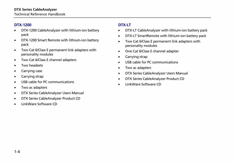
DTX-1200 • DTX-1200 CableAnalyzer with lithium-ion battery
pack
• DTX-1200 Smart Remote with lithium-ion battery pack
• Two Cat 6/Class E permanent link adapters with personality modules
• Two Cat 6/Class E channel adapters
• Two headsets
• Carrying case
• Carrying strap
• USB cable for PC communications
• Two ac adapters
• DTX Series CableAnalyzer Users Manual
• DTX Series CableAnalyzer Product CD
• LinkWare Software CD
DTX-LT • DTX-LT CableAnalyzer with lithium-ion battery pack
• DTX-LT SmartRemote with lithium-ion battery pack
• Two Cat 6/Class E permanent link adapters with personality modules
• One Cat 6/Class E channel adapter
• Carrying strap
• USB cable for PC communications
• Two ac adapters
• DTX Series CableAnalyzer Users Manual
• DTX Series CableAnalyzer Product CD
• LinkWare Software CD
Getting Acquainted Unpacking 1
1-5
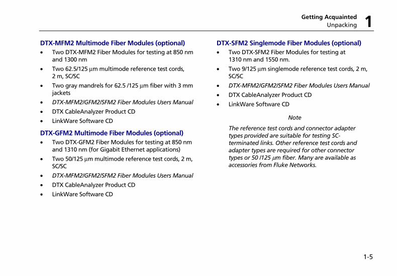
DTX-MFM2 Multimode Fiber Modules (optional) • Two DTX-MFM2 Fiber Modules for testing at 850 nm
and 1300 nm
• Two 62.5/125 µm multimode reference test cords, 2 m, SC/SC
• Two gray mandrels for 62.5 /125 µm fiber with 3 mm jackets
• DTX-MFM2/GFM2/SFM2 Fiber Modules Users Manual
• DTX CableAnalyzer Product CD
• LinkWare Software CD
DTX-GFM2 Multimode Fiber Modules (optional) • Two DTX-GFM2 Fiber Modules for testing at 850 nm
and 1310 nm (for Gigabit Ethernet applications)
• Two 50/125 µm multimode reference test cords, 2 m, SC/SC
• DTX-MFM2/GFM2/SFM2 Fiber Modules Users Manual
• DTX CableAnalyzer Product CD
• LinkWare Software CD
DTX-SFM2 Singlemode Fiber Modules (optional) • Two DTX-SFM2 Fiber Modules for testing at
1310 nm and 1550 nm.
• Two 9/125 µm singlemode reference test cords, 2 m, SC/SC
• DTX-MFM2/GFM2/SFM2 Fiber Modules Users Manual
• DTX CableAnalyzer Product CD
• LinkWare Software CD
Note
The reference test cords and connector adapter types provided are suitable for testing SC-terminated links. Other reference test cords and adapter types are required for other connector types or 50 /125 µm fiber. Many are available as accessories from Fluke Networks.
DTX Series CableAnalyzer Technical Reference Handbook
1-6
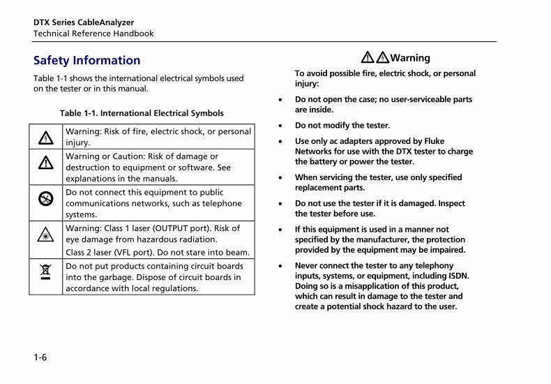
Safety Information Table 1-1 shows the international electrical symbols used on the tester or in this manual.
Table 1-1. International Electrical Symbols
X Warning: Risk of fire, electric shock, or personal injury.
W Warning or Caution: Risk of damage or destruction to equipment or software. See explanations in the manuals.
j Do not connect this equipment to public communications networks, such as telephone systems.
* Warning: Class 1 laser (OUTPUT port). Risk of eye damage from hazardous radiation.
Class 2 laser (VFL port). Do not stare into beam.
~ Do not put products containing circuit boards into the garbage. Dispose of circuit boards in accordance with local regulations.
WXWarning
To avoid possible fire, electric shock, or personal injury:
• Do not open the case; no user-serviceable parts are inside.
• Do not modify the tester.
• Use only ac adapters approved by Fluke Networks for use with the DTX tester to charge the battery or power the tester.
• When servicing the tester, use only specified replacement parts.
• Do not use the tester if it is damaged. Inspect the tester before use.
• If this equipment is used in a manner not specified by the manufacturer, the protection provided by the equipment may be impaired.
• Never connect the tester to any telephony inputs, systems, or equipment, including ISDN. Doing so is a misapplication of this product, which can result in damage to the tester and create a potential shock hazard to the user.
Getting Acquainted Safety Information 1
1-7
• Always turn on the tester before connecting it to a cable. Turning the tester on activates the tool’s input protection circuitry.
• Do not use the tester if it operates abnormally. Protection may be impaired.
WCaution To avoid disrupting network operation, to avoid damaging the tester or cables under test, to avoid data loss, and to ensure maximum accuracy of test results:
• Never connect the tester to an active network. Doing so may disrupt network operation.
• Never attempt to insert any connector other than an 8-pin modular (RJ45) connector into an adapter’s jack. Inserting other connectors, such as RJ11 (telephone) connectors, can permanently damage the jack.
• Never operate portable transmitting devices, such as walkie-talkies and cell phones, during a cable test. Doing so might cause erroneous test results.
• To ensure maximum accuracy of copper cable test results, perform the reference procedure every thirty days as described under “Setting the Reference” in Chapters 3 and 4.
• The permanent link interface adapters may not perform properly or may be damaged if they are handled improperly. See pages 1-18 and 1-19 for important handling information.
• Turn off the tester before attaching or removing modules.
• Leave the module bay covers in place when the fiber modules are not installed. See page 1-10.
• Never remove the memory card while the memory card’s LED is on. Doing so can corrupt the data on the card.
W* Warning: Class 1 and Class 2 Laser Products
To avoid possible eye damage caused by hazardous radiation, when using the fiber modules follow the safety guidelines given in Chapter 6 of this manual.
DTX Series CableAnalyzer Technical Reference Handbook
1-8
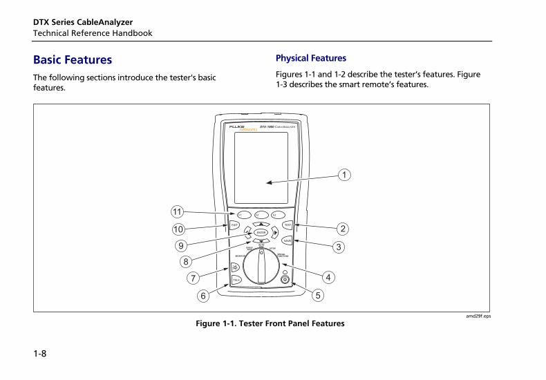
Basic Features The following sections introduce the tester's basic features.
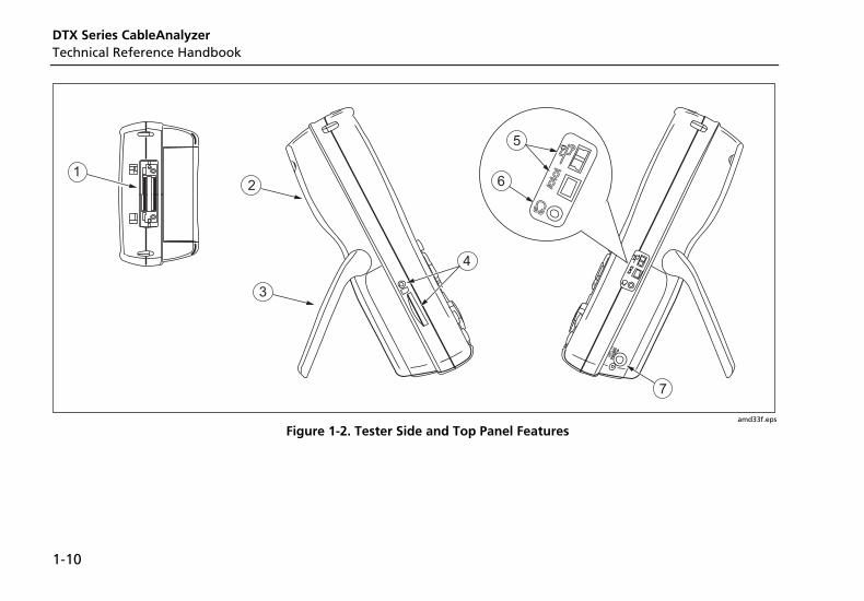
Physical Features
Figures 1-1 and 1-2 describe the tester’s features. Figure 1-3 describes the smart remote’s features.
TALK
MONITOR
ENTER
TEST
SAVE
SPECIAL FUNCTIONS
SETUP
AUTO TESTSINGLE
TEST
EXIT
F1 F2 F3
1
2
3
4
56
7
8
9
10
11
amd29f.eps
Figure 1-1. Tester Front Panel Features
Getting Acquainted Basic Features 1
1-9
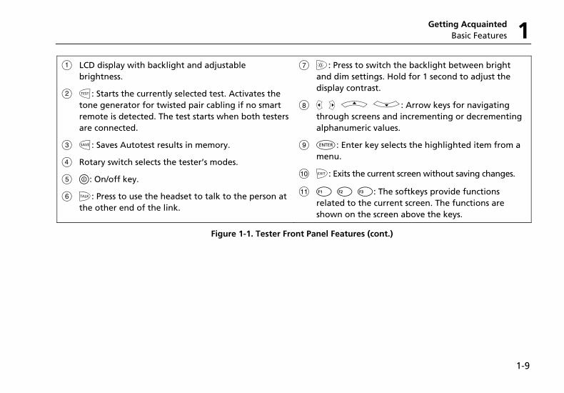
A LCD display with backlight and adjustable brightness.
B P: Starts the currently selected test. Activates the tone generator for twisted pair cabling if no smart remote is detected. The test starts when both testers are connected.
C N: Saves Autotest results in memory.
D Rotary switch selects the tester’s modes.
E M: On/off key.
F O: Press to use the headset to talk to the person at the other end of the link.
G G: Press to switch the backlight between bright and dim settings. Hold for 1 second to adjust the display contrast.
H B C A D: Arrow keys for navigating through screens and incrementing or decrementing alphanumeric values.
I H: Enter key selects the highlighted item from a menu.
J I: Exits the current screen without saving changes.
K A B C: The softkeys provide functions related to the current screen. The functions are shown on the screen above the keys.
Figure 1-1. Tester Front Panel Features (cont.)
DTX Series CableAnalyzer Technical Reference Handbook
1-10
amd33f.eps
Figure 1-2. Tester Side and Top Panel Features
Getting Acquainted Basic Features 1
1-11
A Connector for twisted pair interface adapters.
B Cover for the module bay. Slide off the cover to install optional modules, such as the fiber module.
C Bail.
D DTX-1800 and DTX-1200: Slot and activity LED for the removable memory card. To eject the card, push in then release the card.
E USB ( ) and RS-232C ( : DTX-1800, DTX-1200) ports for uploading test reports to a PC and updating the tester’s software. The RS-232C port uses a custom DTX cable available from Fluke Networks. See Chapter 12 for more information.
F Headset jack for talk mode.
G Connector for the ac adapter. The LED turns on when the tester is connected to ac power.
• Red: Battery is charging.
• Green: Battery is charged.
• Flashing red: Charge timeout. The battery failed to reach full charge within 6 hours. See “If Something Seems Wrong” in Chapter 12.
Figure 1-2. Tester Side and Top Panel Features (cont.)
DTX Series CableAnalyzer Technical Reference Handbook
1-12
amd30f.eps
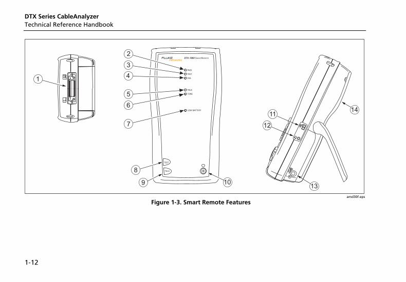
Figure 1-3. Smart Remote Features
Getting Acquainted Basic Features 1
1-13
WCaution All the LEDs flash if the smart remote detects excessive voltage on the cable. Unplug the cable immediately if this occurs.
Note
The LEDs also act as a battery gauge. See Figure 1-5 on page 1-17.
A Connector for twisted pair interface adapters.
B Pass LED lights when a test passes.
C Test LED lights during cable tests.
D Fail LED lights when a test fails.
E Talk LED lights when the smart remote is in talk mode. Press Oto adjust the volume.
F Tone LED lights and the tone generator turns on when you press P, but the main tester is not connected.
G Low battery LED lights when the battery is low.
H P: Starts the test currently selected on the main unit. Activates the tone generator for twisted pair cabling if no main tester is detected. The test starts when both testers are connected.
I O: Press to use the headset to talk to the person at the other end of the link. Press again to adjust the volume. Press and hold to exit talk mode.
J M: On/off key.
K USB port for updating the tester’s software with a PC.
L Headset jack for talk mode.
M Connector for the ac adapter, as described in Figure 1-2.
N Cover for the module bay. Slide off the cover to install optional modules, such as the fiber module.
Figure 1-3. Smart Remote Features (cont.)
DTX Series CableAnalyzer Technical Reference Handbook
1-14
Changing the Language
To change the tester’s language:
1 Turn the rotary switch to SETUP.
2 Use D to highlight Instrument Settings at the bottom of the list; then press H.
3 Use Cand D to find and highlight Language on tab 2 at the bottom of the list; then press H.
4 Use D to highlight the desired language; then press H.
5 Use the arrow keys and H to find and change other local settings on tabs 2, 3, and 4 under Instrument Settings.
Powering the Tester
*WWarning Read the safety information at the beginning of Chapter 2 before using the tester.
You can power the tester with the ac adapter included or with the removable lithium ion battery pack.
If the tester does not turn on, refer to “If Something Seems Wrong” in Chapter 12.
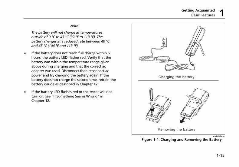
Charging the Battery
• To charge the battery, connect the ac adapter to the battery pack, as shown in Figure 1-4.
• You may charge the battery when it is attached or detached from the tester. Figure 1-4 shows how to remove the battery.
• The battery charges fully in about 4 hours with the tester off. A fully-charged battery lasts for at least 12 hours of typical use.
Getting Acquainted Basic Features 1
1-15
Note
The battery will not charge at temperatures outside of 0 °C to 45 °C (32 °F to 113 °F). The battery charges at a reduced rate between 40 °C and 45 °C (104 °F and 113 °F).
• If the battery does not reach full charge within 6 hours, the battery LED flashes red. Verify that the battery was within the temperature range given above during charging and that the correct ac adapter was used. Disconnect then reconnect ac power and try charging the battery again. If the battery does not charge the second time, retrain the battery gauge as described in Chapter 12.
• If the battery LED flashes red or the tester will not turn on, see “If Something Seems Wrong” in Chapter 12.
Removing the battery
Charging the battery
amd124f.eps
Figure 1-4. Charging and Removing the Battery
DTX Series CableAnalyzer Technical Reference Handbook
1-16
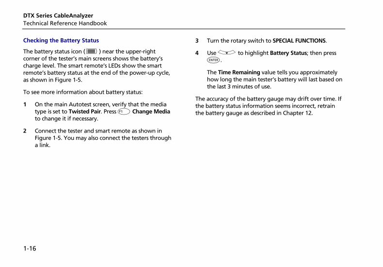
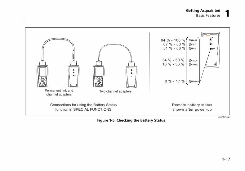
Checking the Battery Status
The battery status icon ( ) near the upper-right corner of the tester’s main screens shows the battery’s charge level. The smart remote’s LEDs show the smart remote’s battery status at the end of the power-up cycle, as shown in Figure 1-5.
To see more information about battery status:
1 On the main Autotest screen, verify that the media type is set to Twisted Pair. Press J Change Media to change it if necessary.
2 Connect the tester and smart remote as shown in Figure 1-5. You may also connect the testers through a link.
3 Turn the rotary switch to SPECIAL FUNCTIONS.
4 Use D to highlight Battery Status; then press H.
The Time Remaining value tells you approximately how long the main tester’s battery will last based on the last 3 minutes of use.
The accuracy of the battery gauge may drift over time. If the battery status information seems incorrect, retrain the battery gauge as described in Chapter 12.
Getting Acquainted Basic Features 1
1-17
TEST
LOW BATTERY
TONE
TALK
FAIL
TEST
PASS
TALK
LOW BA
TONE
TALK
FAIL
TEST
PASS
Remote battery statusshown after power-up
PM06
TEST
LOW BATTERY
TONE
TALK
FAIL
TEST
PASS
TALKTALK
MONITOR
ENTER
TEST
SAVE
SPECIALFUNCTIONS
SETUP
AUTOTESTSINGLE
TEST
EXIT
F1 F2 F3
TEST
LOW BATTERY
TONE
TALK
FAIL
TEST
PASS
TALK
TALK
MONITOR
ENTER
TEST
SAVE
SPECIALFUNCTIONS
SETUP
AUTOTESTSINGLE
TEST
EXIT
F1 F2 F3
Connections for using the Battery Statusfunction in SPECIAL FUNCTIONS
TEST
LOW BATTERY
TONE
TALK
FAIL
TEST
PASS
TALK
TEST
LOW BATTERY
TONE
TALK
FAIL
TEST
PASS
TALK
TEST
LOW BATTERY
TONE
TALK
FAIL
TEST
PASS
TALK
TEST
LOW BATTERY
TONE
TALK
FAIL
TEST
PASS
TALK
TEST
LOW BATTERY
TONE
TALK
FAIL
TEST
PASS
TALK
Permanent link andchannel adapters
Two channel adapters
0 % - 17 %
18 % - 33 %34 % - 50 %
51 % - 66 %67 % - 83 %
84 % - 100 %
amd102f.eps
Figure 1-5. Checking the Battery Status
DTX Series CableAnalyzer Technical Reference Handbook
1-18
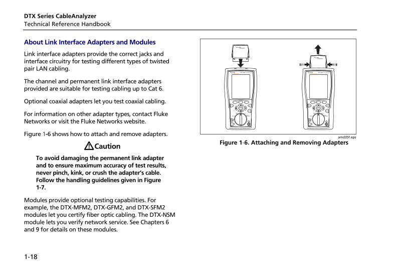
About Link Interface Adapters and Modules
Link interface adapters provide the correct jacks and interface circuitry for testing different types of twisted pair LAN cabling.
The channel and permanent link interface adapters provided are suitable for testing cabling up to Cat 6.
Optional coaxial adapters let you test coaxial cabling.
For information on other adapter types, contact Fluke Networks or visit the Fluke Networks website.
Figure 1-6 shows how to attach and remove adapters.
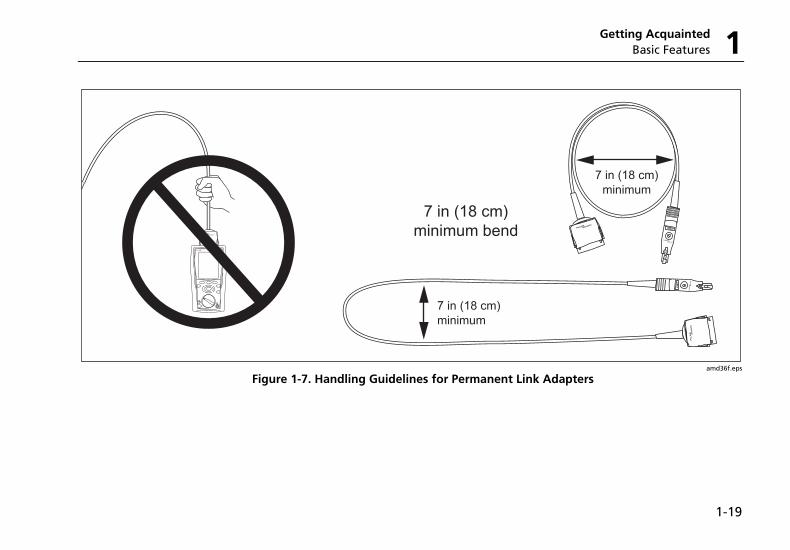
WCaution
To avoid damaging the permanent link adapter and to ensure maximum accuracy of test results, never pinch, kink, or crush the adapter’s cable. Follow the handling guidelines given in Figure 1-7.
Modules provide optional testing capabilities. For example, the DTX-MFM2, DTX-GFM2, and DTX-SFM2 modules let you certify fiber optic cabling. The DTX-NSM module lets you verify network service. See Chapters 6 and 9 for details on these modules.
TALK
MONITOR
ENTER
TEST
SAVE
SPECIAL FUNCTIONS
SETUP
AUTO TESTSINGLE
TEST
EXIT
F1 F2 F3
TALK
MONITOR
ENTER
TEST
SAVE
SPECIAL FUNCTIONS
SETUP
AUTO TESTSINGLE
TEST
EXIT
F1 F2 F3
amd35f.eps
Figure 1-6. Attaching and Removing Adapters
Getting Acquainted Basic Features 1
1-19
amd36f.eps
Figure 1-7. Handling Guidelines for Permanent Link Adapters
DTX Series CableAnalyzer Technical Reference Handbook
1-20
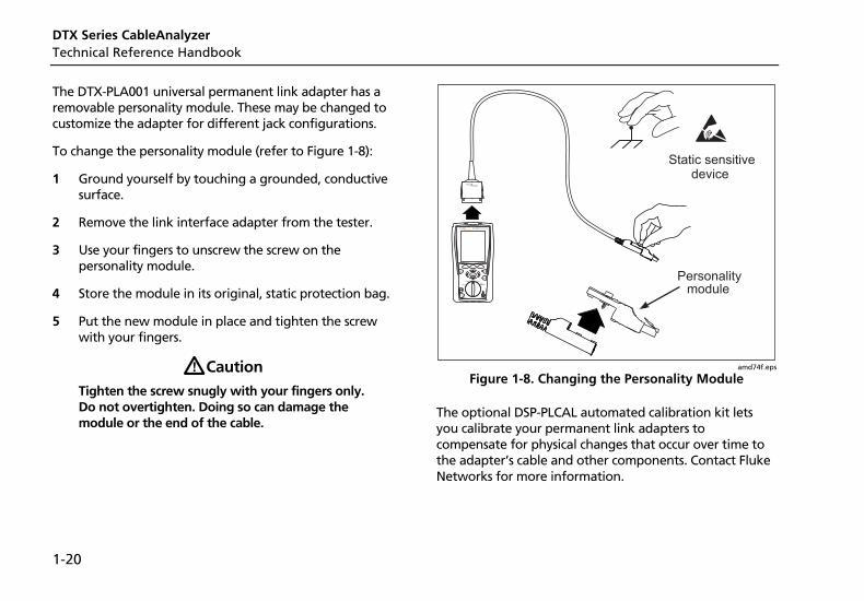
The DTX-PLA001 universal permanent link adapter has a removable personality module. These may be changed to customize the adapter for different jack configurations.
To change the personality module (refer to Figure 1-8):
1 Ground yourself by touching a grounded, conductive surface.
2 Remove the link interface adapter from the tester.
3 Use your fingers to unscrew the screw on the personality module.
4 Store the module in its original, static protection bag.
5 Put the new module in place and tighten the screw with your fingers.
WCaution Tighten the screw snugly with your fingers only. Do not overtighten. Doing so can damage the module or the end of the cable.
Static sensitivedevice
Personalitymodule
TALK
MONITOR
ENTER
TEST
SAVE
SPECIAL FUNCTIONS
SETUP
AUTO TESTSINGLE
TEST
EXIT
F1 F2 F3
amd74f.eps
Figure 1-8. Changing the Personality Module
The optional DSP-PLCAL automated calibration kit lets you calibrate your permanent link adapters to compensate for physical changes that occur over time to the adapter’s cable and other components. Contact Fluke Networks for more information.
Getting Acquainted Basic Features 1
1-21
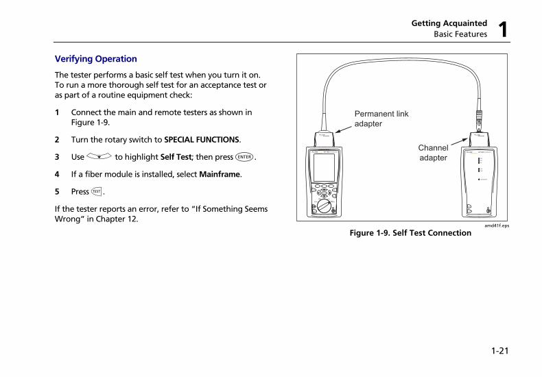
Verifying Operation
The tester performs a basic self test when you turn it on. To run a more thorough self test for an acceptance test or as part of a routine equipment check:
1 Connect the main and remote testers as shown in Figure 1-9.
2 Turn the rotary switch to SPECIAL FUNCTIONS.
3 Use D to highlight Self Test; then press H.
4 If a fiber module is installed, select Mainframe.
5 Press P.
If the tester reports an error, refer to “If Something Seems Wrong” in Chapter 12.
PM06
Permanent link
adapter
Channel
adapter
TEST
LOW BATTERY
TONE
TALK
FAIL
TEST
PASS
TALKTALK
MONITOR
ENTER
TEST
SAVE
SPECIAL FUNCTIONS
SETUP
AUTO TESTSINGLE
TEST
EXIT
F1 F2 F3
amd41f.eps
Figure 1-9. Self Test Connection
DTX Series CableAnalyzer Technical Reference Handbook
1-22
Checking the Hardware and Software Versions
To see information about the tester’s hardware, software, and the test limits and cable types databases:
1 Connect the tester and smart remote through adapters, as in Figure 1-9.
2 Turn the rotary switch to SPECIAL FUNCTIONS.
3 Use D to highlight Version Information; then press H.
4 Use the softkeys to switch between the tester and remote’s information, and between information for the mainframe and any modules or adapters attached.
To determine if your tester needs a software update, visit the Fluke Networks website to see if an update is available. See Chapter 12 for details on updating the tester's software.
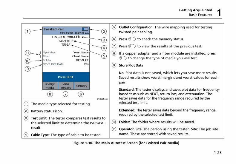
The Main Autotest Screen
The Autotest automatically runs all the tests necessary to certify that cabling meets the requirements of the selected test limit. You will probably use the Autotest more than any other of the tester’s functions.
When you first turn the rotary switch to AUTOTEST, the main Autotest screen shows settings you should check before you start testing. Figure 1-10 describes this screen. You can change these settings in SETUP, as described in Chapters 2, 3, 4, and 6.
Getting Acquainted Basic Features 1
1-23
1
678
9
11
2
3
4
105
amd05f.eps
A The media type selected for testing.
B Battery status icon.
C Test Limit: The tester compares test results to the selected limit to determine the PASS/FAIL result.
D Cable Type: The type of cable to be tested.
E Outlet Configuration: The wire mapping used for testing twisted pair cabling.
F Press L to check the memory status.
G Press K to view the results of the previous test.
H If a copper adapter and a fiber module are installed, press J to change the type of media you will test.
I Store Plot Data
No: Plot data is not saved, which lets you save more results. Saved results show worst margins and worst values for each pair.
Standard: The tester displays and saves plot data for frequency-based tests such as NEXT, return loss, and attenuation. The tester saves data for the frequency range required by the selected test limit.
Extended: The tester saves data beyond the frequency range required by the selected test limit.
J Folder: The folder where results will be saved.
K Operator, Site: The person using the tester. Site: The job site name. These are stored with saved results.
Figure 1-10. The Main Autotest Screen (for Twisted Pair Media)
DTX Series CableAnalyzer Technical Reference Handbook
1-24
Setting User Preferences The following sections describe how to change settings you may want to adjust when you first start using the tester.
Changing the Date, Time, and Date/Time Formats
1 Turn the rotary switch to SETUP, use D to highlight Instrument Settings; then press H.
2 Press Cto go to the tab with the Date and Time selections.
3 Use D to highlight the setting you want to change; then press H.
4 To change numbers in the date or time on the Date or Time screen, use B C to highlight the number; then use A D to change the number.
Press N when you are done.
5 To change the date or time format, press J Change Format on the Date or Time screen. Use D to highlight the format you want; then press H.
Changing the Length Units
1 Turn the rotary switch to SETUP, use D to highlight Instrument Settings; then press H.
2 Press Cto go to the tab with the Length Units selection.
3 Use D to highlight Length Units; then press H.
4 Use D to highlight the setting you want; then press H.
Changing the Numeric Format
The tester can show decimal fractions with a decimal point (0.00) or a comma (0,00).
1 Turn the rotary switch to SETUP, use D to highlight Instrument Settings; then press H.
2 Press Cto go to the tab with the Numeric Format selection.
3 Use D to highlight Numeric Format; then press H.
4 Use D to highlight the setting you want; then press H.
Getting Acquainted Setting User Preferences 1
1-25
Adjusting the Display Contrast
1 Press and hold G.
2 Use B C for coarse adjustments and K Fine L Fine for fine adjustments.
J Default Setting sets the contrast to the default level.
3 Press H when you are done.
The setting is retained when you turn the tester off. The contrast setting does not affect the battery life.
Setting the Power Down Timer
The power down timer turns off the tester after a selected period of inactivity. The timer starts when the backlight timer times out. If the backlight timer is disabled, the power down timer starts whenever the tester is not being used.
The smart remote turns off after 30 minutes of inactivity. This setting is not adjustable.
Note
The power down timer is inactive when the ac adapter is connected or when the USB or RS-232 serial port is active.
To set the power down timer:
1 Turn the rotary switch to SETUP, use D to highlight Instrument Settings; then press H.
2 Press C to go to the tab with the Power Down Time-Out setting; then press H.
3 Use D to highlight the setting you want; then press H.
Setting the Backlight Timer
The backlight timer turns off the backlight after a selected period of inactivity. Using the timer to turn off the backlight helps conserve battery power.
To set the backlight timer;
1 Turn the rotary switch to SETUP, use D to highlight Instrument Settings; then press H.
2 Press C to go to the tab with the Backlight Time-Out setting. Use D to highlight Backlight Time-Out; then press H.
3 Use D to highlight the setting you want; then press H.
DTX Series CableAnalyzer Technical Reference Handbook
1-26
Enabling or Disabling the Beeper
To enable or disable the tones for key presses and testing progress:
1 Turn the rotary switch to SETUP, use D to highlight Instrument Settings; then press H.
2 Press C to go to the tab with the Audible Tone setting. Use D to highlight Audible Tone; then press H.
3 Use D to highlight the setting you want; then press H.
Overview of Memory Features All DTX testers have internal memory that can store at least 250 Autotest results, including graphical data. The maximum capacity of internal memory depends on the space taken by the tester’s software.
The DTX-1800 and DTX-1200 testers can also store up to 500 Cat 6 Autotest results, including graphical data, on a 16 MB card. The testers can also use cards with higher capacity and secure digital (SD) memory cards.
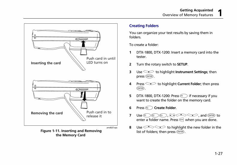
Inserting and Removing the Memory Card
Insert the memory card into the slot on the side of the tester. Figure 1-11 shows how to insert and remove the card.
Formatting the Memory Card (DTX-1800 and DTX-1200) or Internal Memory
Formatting erases all contents of the memory card or internal memory.
To format the memory card or internal memory:
1 Turn the rotary switch to SPECIAL FUNCTIONS, then select Memory Status.
2 For a DTX-1800 or DTX-1200 with a memory card installed, press J to select the memory card or internal memory.
3 Press K Format.
Getting Acquainted Overview of Memory Features 1
1-27
Push card in untilLED turns onInserting the card
Removing the card Push card in torelease it
amd62f.eps
Figure 1-11. Inserting and Removing the Memory Card
Creating Folders
You can organize your test results by saving them in folders.
To create a folder:
1 DTX-1800, DTX-1200: Insert a memory card into the tester.
2 Turn the rotary switch to SETUP.
3 Use D to highlight Instrument Settings; then press H.
4 Press D to highlight Current Folder; then press H.
5 DTX-1800, DTX-1200: Press J if necessary if you want to create the folder on the memory card.
6 Press L Create Folder.
7 Use JKL, BCAD, and H to enter a folder name. Press N when you are done.
8 Use AD to highlight the new folder in the list of folders; then press H.
DTX Series CableAnalyzer Technical Reference Handbook
1-28
Setting the Storage Location (DTX-1800 and DTX-1200)
To set the destination for saved results on a DTX-1800 or DTX-1200 tester:
1 Turn the rotary switch to SETUP, use D to highlight Instrument Settings; then press H.
2 Use D to highlight Result Storage Location; then press H.
4 Use D to highlight Internal Memory or Memory Card (if present); then press H.
Note
If you change storage location, and the selected Current Folder does not exist in the new location, the tester creates a new folder with the current folder’s name in the new location.
See Chapter 12 for more information on memory features.
Options for Entering Cable IDs
When you save a test, you enter a name for the test. At a job site, you usually name each test with the identification code assigned to the link tested. You can enter this ID character by character, or by selecting the ID from a pre-generated list.
To select a method for entering cable IDs:
1 Turn the rotary switch to SETUP.
2 Use D to highlight Instrument Settings, then press H.
3 Press H to select Cable ID Source.
4 Use D to highlight an ID source, then press H.
Getting Acquainted Overview of Memory Features 1
1-29
The tester offers the following methods for entering cable IDs:
• Auto Increment: You enter an ID for the first test you save. After that, the tester increments the last character of the ID each time you press N. See Chapter 2 for details.
• List: Lets you select IDs from a list created with LinkWare software and downloaded to the tester. See the LinkWare online help for details. The ID list can be sequential or random.
• Auto Sequence: Lets you select IDs from a list of sequential IDs generated from a template in SETUP. The horizontal, backbone, and campus templates follow the ID formats specified in the ANSI/TIA/EIA-606-A standard. The Free Form template lets you create your own pattern. See Chapter 2 for details.
• None: Lets you create an ID each time you press N.
After you press N, you can also edit an existing ID before using it for saving results.
To create a list of sequential IDs:
1 On the Auto Sequence screen, select a template.
2 On the Auto Sequence screen, select Start ID. Use the softkeys, BC A D, and H to enter the first ID in the sequential list. Press N when you are finished.
3 Select Stop ID. Use the softkeys, BC A D, and H to enter the last ID in the sequential list. Press N when you are finished
4 Press L Sample List to see what the list will look like.
When you use an ID from a list, the ID is marked with a “$”.
See Chapter 2 for more information on the Auto Sequence feature.
DTX Series CableAnalyzer Technical Reference Handbook
1-30
Using the Talk Mode The talk mode lets you talk to the person at the other end of a twisted pair or fiber link. Two-way communication over twisted pair requires one good wire pair. Two-way communication over fiber requires fiber modules and two fibers.
Note
The talk mode is disabled during cable tests.
1 Connect the tester and smart remote to the cabling.
2 Plug headsets into the headset jacks on the testers.
3 Press O on either the tester or smart remote, then speak into the headset’s microphone.
To adjust the volume at the main unit use AD.
At the smart remote, use O to cycle through the volume settings.
4 To exit the talk mode at the main tester, press I, turn the rotary switch to a new position, or start a test. At the smart remote, hold down O for two seconds.
About LinkWare and LinkWare Stats Software The LinkWare Cable Test Management software included with your tester lets you do the following:
• Upload DTX test results to PC. See Chapter 12.
• View test results.
• Add ANSI/TIA/EIA-606-A administration information to records.
• Organize, customize, and print professional-quality test reports.
• Update the tester’s software.
• Create and download data to the DTX, such as Setup data and cable ID lists.
• Calibrate the permanent link adapters (DSP-PLCAL kit required)
• Transfer custom limits between testers.
Getting Acquainted About LinkWare and LinkWare Stats Software 1
1-31
Details about using LinkWare software are provided in the LinkWare Getting Started Guide and the online help available under Help on the LinkWare menu.
Updates to LinkWare software are available on the Fluke Networks website.
The LinkWare Stats Statistical Report option for LinkWare software provides statistical analysis of cable test reports and generates browsable, graphical reports.
LinkWare software includes a demo version of LinkWare Stats. Contact Fluke Networks or visit the Fluke Networks website for more information on LinkWare Stats.
DTX Series CableAnalyzer Technical Reference Handbook
1-32
2-1
Chapter 2 Tutorials on Setup and Test Procedures
The tutorials in this chapter guide you through setting up the tester, checking the tester’s status, testing twisted pair and fiber cabling, and setting up cable ID lists.
Preparing to Save Tests Step 1: Checking the Memory Space Available
1-1 DTX-1800, DTX-1200: Insert a memory card into the tester.
1-2 Turn the rotary switch to SPECIAL FUNCTIONS.
1-3 Use D to highlight Memory Status; then press H.
1-4 DTX-1800, DTX-1200: Press J Int. Memory to switch between memory card and internal memory status.
DTX Series CableAnalyzer Technical Reference Handbook
2-2
Step 2: Entering Job Information
Job information includes the operator name, name of the job site, and the customer’s company name. These settings are stored with results you save.
To enter job information:
2-1 Turn the rotary switch to SETUP.
2-2 Use D to highlight Instrument Settings; then press H.
2-3 Press C to go to the tab with the Operator Name setting. Press H to select Operator Name.
2-4 Press J Create; then use JKL, BCAD, and H to enter your name in the box. Press N when you are done.
2-5 Figure 2-1 describes the text editing screen.
2-6 Use D to highlight Site; then press H.
2-7 Press J Create; then use JKL, BCAD, and H to enter the job site name in the box. Press N when you are done.
2-8 Repeat steps 2-6 and 2-7 to enter the customer’s Company name.
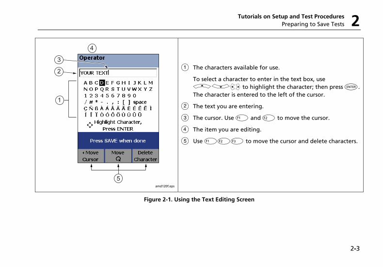
Tutorials on Setup and Test Procedures Preparing to Save Tests 2
2-3
1
2
3
4
5 amd120f.eps
A The characters available for use.
To select a character to enter in the text box, use ADBC to highlight the character; then press H. The character is entered to the left of the cursor.
B The text you are entering.
C The cursor. Use J and K to move the cursor.
D The item you are editing.
E Use JKL to move the cursor and delete characters.
Figure 2-1. Using the Text Editing Screen
DTX Series CableAnalyzer Technical Reference Handbook
2-4
Step 3: Setting the Storage Location (DTX-1800 and DTX-1200)
To set the destination for saved results on a DTX-1800 or DTX-1200 tester:
3-1 Turn the rotary switch to SETUP, use D to highlight Instrument Settings; then press H.
3-2 Use D to highlight Result Storage Location; then press H.
3-3 Use D to highlight Internal Memory or Memory Card (if present); then press H.
Note
If you change storage location, and the selected Current Folder does not exist in the new location, the tester creates a new folder with the current folder’s name in the new location.
Step 4: Setting Up a Job Folder
You can organize test results by saving them in a folder named for the job.
To set up a job folder:
4-1 DTX-1800, DTX-1200: Insert a memory card into the tester, if that is where you wan to create a folder.
4-2 Turn the rotary switch to SETUP.
4-3 Use D to highlight Instrument Settings; then press H.
4-4 Press D to highlight Current Folder; then press H.
4-5 Press J Create Folder.
4-6 Use JKL, BCAD, and H to enter a folder name. Press N when you are done.
4-7 Use AD to highlight the new folder in the list of folders; then press H.
Tutorials on Setup and Test Procedures Certifying Twisted Pair Cabling 2
2-5
Step 5: Selecting a Cable ID Source
Cable IDs are names you enter for tests you save. You can select IDs from a pre-generated list, or enter them manually after each test. For this tutorial, you will enter IDs manually.
To select a cable ID source:
5-1 Turn the rotary switch to SETUP.
5-2 Use D to highlight Instrument Settings; then press H.
5-3 Press H to select Cable ID Source.
5-4 Use D to highlight None; then press H.
Certifying Twisted Pair Cabling This tutorial familiarizes you with testing twisted pair cabling by guiding you through the following tasks:
• Attaching twisted pair adapters
• Checking the battery status and verifying operation with twisted pair adapters
• Running an Autotest
• Viewing the Autotest results
• Saving the results
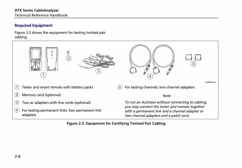
DTX Series CableAnalyzer Technical Reference Handbook
2-6
Required Equipment
Figure 2-2 shows the equipment for testing twisted pair cabling.
PM06
PM06
1
2
3
4
5TEST
LOW BATTERY
TONE
TALK
FAIL
TEST
PASS
TALKTALK
MONITOR
ENTER
TEST
SAVE
SPECIAL FUNCTIONS
SETUP
AUTO TESTSINGLE
TEST
EXIT
F1 F2 F3
amd40f.eps
A Tester and smart remote with battery packs
B Memory card (optional)
C Two ac adapters with line cords (optional)
D For testing permanent links: two permanent link adapters
E For testing channels: two channel adapters
Note
To run an Autotest without connecting to cabling, you may connect the tester and remote together with a permanent link and a channel adapter or two channel adapters and a patch cord.
Figure 2-2. Equipment for Certifying Twisted Pair Cabling
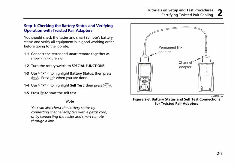
Tutorials on Setup and Test Procedures Certifying Twisted Pair Cabling 2
2-7
Step 1: Checking the Battery Status and Verifying Operation with Twisted Pair Adapters
You should check the tester and smart remote’s battery status and verify all equipment is in good working order before going to the job site.
1-1 Connect the tester and smart remote together as shown in Figure 2-3.
1-2 Turn the rotary switch to SPECIAL FUNCTIONS.
1-3 Use D to highlight Battery Status; then press H. Press I when you are done.
1-4 Use D to highlight Self Test; then press H.
1-5 Press Pto start the self test.
Note
You can also check the battery status by connecting channel adapters with a patch cord, or by connecting the tester and smart remote through a link.
PM06
Permanent link
adapter
Channel
adapter
TEST
LOW BATTERY
TONE
TALK
FAIL
TEST
PASS
TALKTALK
MONITOR
ENTER
TEST
SAVE
SPECIAL FUNCTIONS
SETUP
AUTO TESTSINGLE
TEST
EXIT
F1 F2 F3
amd117f.eps
Figure 2-3. Battery Status and Self Test Connections for Twisted Pair Adapters
DTX Series CableAnalyzer Technical Reference Handbook
2-8
Step 2: Selecting a Test Limit, Cable Type, and Outlet Configuration
Select the test limit, cable type, and outlet configuration specified for the job. The outlet configuration determines which cable pairs are tested and which pair numbers are assigned to the pairs.
2-1 Turn the rotary switch to SETUP; then press H to select Twisted Pair.
2-2 On the Twisted Pair menu use D and H to select Cable Type. Cables are organized in groups:
UTP: Unshielded twisted pair cable
FTP: Foil screened twisted pair cable
SSTP: Screened/shielded twisted pair cable
Custom: Cable types entered by a DTX user.
Manufacturer: Specific brands of twisted pair cable
2-3 Use D to highlight the group for the cable type you will test; then press H.
2-4 Use D to highlight the cable type you will test; then press H.
2-5 On the Twisted Pair menu, press H to select Test Limit.
2-6 The first Test Limit screen shows the most recently-used limits. To see the list of test limit groups, press JMore.
2-7 Use D and H to select a different limit group, if necessary, and to select the test limit required for the job.
If you are connecting the permanent link and channel adapters together just to try an Autotest, select a Cat 6 Channel or equivalent limit.
2-8 If the currently-selected Outlet Configuration is not compatible with the selected Test Limit, the Outlet Configuration screen appears. Use AD to highlight an appropriate configuration; then press H.
Step 3: Running the Autotest
3-1 Attach the correct adapters to the tester and smart remote.
3-2 Turn on the tester and smart remote; then connect them to the cabling. Figures 2-4 and 2-5 show connections for permanent link and channel installations.
Tutorials on Setup and Test Procedures Certifying Twisted Pair Cabling 2
2-9
To run an Autotest without connecting to installed cabling, connect the tester and remote as shown in Figure 2-3 on page 2-7, or connect using two channel adapters and a patch cord.
3-3 Turn the rotary switch to AUTOTEST.
3-4 If a fiber module is installed, verify that the media type is set to Twisted Pair. Press J Change Media to change it if necessary.
3-5 Press P on the tester or smart remote.
Work area
OptionalconsolidationpointPatch panel Wall
outlet
Horizontal cabling
Endpermanent
link
Startpermanentlink
Tester with permanentlink adapter
Smart remote withpermanent link adapter
TALK
MONITOR
ENTER
TEST
SAVE
SPECIALFUNCTIONS
SETUP
AUTOTESTSINGLE
TEST
EXIT
F1 F2 F3
TEST
LOW BATTERY
TONE
TALK
FAIL
TEST
PASS
TALK
amd22a.eps
Figure 2-4. Permanent Link Test Connections
DTX Series CableAnalyzer Technical Reference Handbook
2-10
Work area
Optional consolidationpoint
Patchpanels
Hub or switch
Wall outlet
Horizontal cabling
Endchannel
Tester withchannel adapter
Smart remote withchannel adapter
Patch cordfrom PC
Patch cordfrom hub or
switch
Startchannel
TEST
LOW BATTERY
TONE
TALK
FAIL
TEST
PASS
TALKTALK
MONITOR
ENTER
TEST
SAVE
SPECIAL FUNCTIONS
SETUP
AUTO TESTSINGLE
TEST
EXIT
F1 F2 F3
amd21f.eps
Figure 2-5. Channel Test Connections
Tutorials on Setup and Test Procedures Certifying Twisted Pair Cabling 2
2-11
Step 4: Viewing the Autotest Results
The Summary screen, shown in Figure 2-6, tells you if the test results met the selected test limit. This screen also shows a status for each measurement:
E: PASS
F: FAIL
i: The results are for informational purposes only. The measurement is not required by the selected test limit.
U: The measurement is within the tester’s accuracy uncertainty range. See Chapter 3 for details.
To see the results for an individual measurement, use D to highlight the test; then press H.
If the test failed, press J Fault Info. for a diagnosis of the fault. Figure 2-6 shows a typical diagnostic screen. The Next Fault softkey is available if the tester detected more than one fault. See Chapter 5 for more information on diagnosing faults.
See Chapter 3 for details on twisted pair test results.
Autotest SummaryScreen
DiagnosticScreen
amd119f.eps
Figure 2-6. Autotest Summary and Diagnostic Screens
DTX Series CableAnalyzer Technical Reference Handbook
2-12
Step 5: Saving the Results
5-1 Press N.
5-2 Use the text editing screen to enter a name for the results. See Figure 2-1 on page 2-3 for details on editing text.
5-3 Press N when you are done.
This concludes the tutorial on testing twisted pair cabling. For more information on testing twisted pair cabling, see Chapter 3.
Certifying Fiber Cabling This section familiarizes you with the optional DTX-MFM2, DTX-GFM2, and DTX-SFM2 fiber modules by guiding you through the following tasks:
• Installing fiber modules
• Checking the battery status and verifying operation with the fiber modules
• Setting a reference in Smart Remote mode
• Running an Autotest in Smart Remote mode
• Viewing the Autotest results
• Saving the results
Required Equipment
Figure 2-7 shows the equipment for testing fiber cabling in Smart Remote mode.
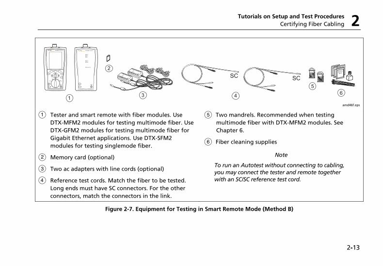
Tutorials on Setup and Test Procedures Certifying Fiber Cabling 2
2-13
amd46f.eps
A Tester and smart remote with fiber modules. Use DTX-MFM2 modules for testing multimode fiber. Use DTX-GFM2 modules for testing multimode fiber for Gigabit Ethernet applications. Use DTX-SFM2 modules for testing singlemode fiber.
B Memory card (optional)
C Two ac adapters with line cords (optional)
D Reference test cords. Match the fiber to be tested. Long ends must have SC connectors. For the other connectors, match the connectors in the link.
E Two mandrels. Recommended when testing multimode fiber with DTX-MFM2 modules. See Chapter 6.
F Fiber cleaning supplies
Note
To run an Autotest without connecting to cabling, you may connect the tester and remote together with an SC/SC reference test cord.
Figure 2-7. Equipment for Testing in Smart Remote Mode (Method B)
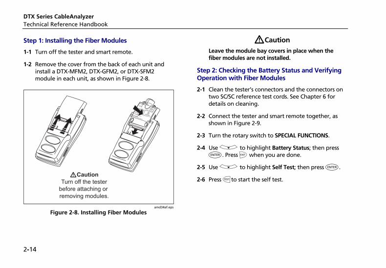
DTX Series CableAnalyzer Technical Reference Handbook
2-14
Step 1: Installing the Fiber Modules
1-1 Turn off the tester and smart remote.
1-2 Remove the cover from the back of each unit and install a DTX-MFM2, DTX-GFM2, or DTX-SFM2 module in each unit, as shown in Figure 2-8.
amd34af.eps
Figure 2-8. Installing Fiber Modules
WCaution Leave the module bay covers in place when the fiber modules are not installed.
Step 2: Checking the Battery Status and Verifying Operation with Fiber Modules
2-1 Clean the tester’s connectors and the connectors on two SC/SC reference test cords. See Chapter 6 for details on cleaning.
2-2 Connect the tester and smart remote together, as shown in Figure 2-9.
2-3 Turn the rotary switch to SPECIAL FUNCTIONS.
2-4 Use D to highlight Battery Status; then press H. Press I when you are done.
2-5 Use D to highlight Self Test; then press H.
2-6 Press Pto start the self test.
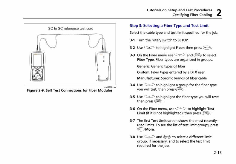
Tutorials on Setup and Test Procedures Certifying Fiber Cabling 2
2-15
TALK
MONITOR
ENTER
TEST
SAVE
SPECIALFUNCTIONS
SETUP
AUTOTESTSINGLE
TEST
EXIT
F1 F2 F3
TALK
TEST
PASS
TEST
FAIL
TALK
TONE
SC to SC reference test cord
amd118f.eps
Figure 2-9. Self Test Connections for Fiber Modules
Step 3: Selecting a Fiber Type and Test Limit
Select the cable type and test limit specified for the job.
3-1 Turn the rotary switch to SETUP.
3-2 Use D to highlight Fiber; then press H.
3-3 On the Fiber menu use D and H to select Fiber Type. Fiber types are organized in groups:
Generic: Generic types of fiber
Custom: Fiber types entered by a DTX user
Manufacturer: Specific brands of fiber cable
3-4 Use D to highlight a group for the fiber type you will test; then press H.
3-5 Use D to highlight the fiber type you will test; then press H.
3-6 On the Fiber menu, use A to highlight Test Limit (if it is not highlighted); then press H.
3-7 The first Test Limit screen shows the most recently-used limits. To see the list of test limit groups, press JMore.
3-8 Use D and H to select a different limit group, if necessary, and to select the test limit required for the job.
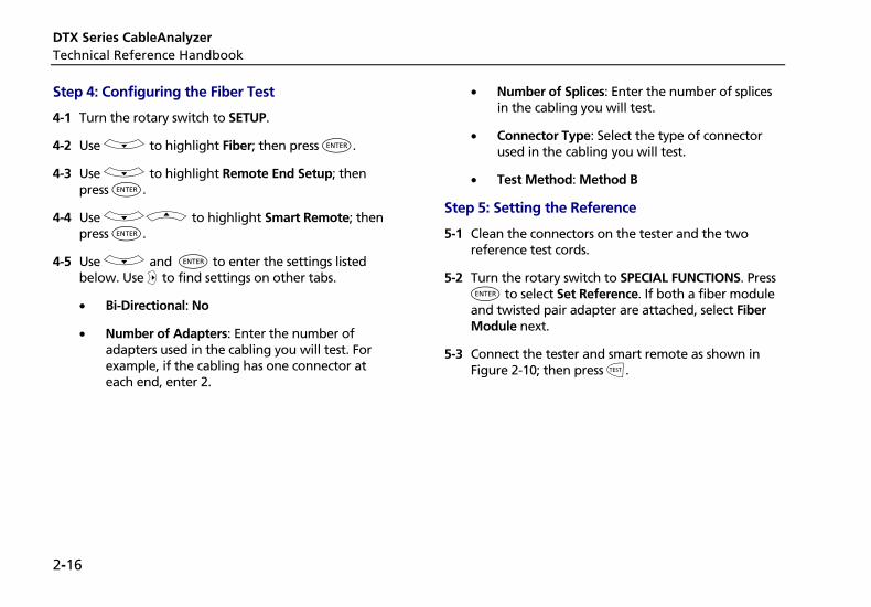
DTX Series CableAnalyzer Technical Reference Handbook
2-16
Step 4: Configuring the Fiber Test
4-1 Turn the rotary switch to SETUP.
4-2 Use D to highlight Fiber; then press H.
4-3 Use D to highlight Remote End Setup; then press H.
4-4 Use DA to highlight Smart Remote; then press H.
4-5 Use D and H to enter the settings listed below. Use C to find settings on other tabs.
• Bi-Directional: No
• Number of Adapters: Enter the number of adapters used in the cabling you will test. For example, if the cabling has one connector at each end, enter 2.
• Number of Splices: Enter the number of splices in the cabling you will test.
• Connector Type: Select the type of connector used in the cabling you will test.
• Test Method: Method B
Step 5: Setting the Reference
5-1 Clean the connectors on the tester and the two reference test cords.
5-2 Turn the rotary switch to SPECIAL FUNCTIONS. Press H to select Set Reference. If both a fiber module and twisted pair adapter are attached, select Fiber Module next.
5-3 Connect the tester and smart remote as shown in Figure 2-10; then press P.
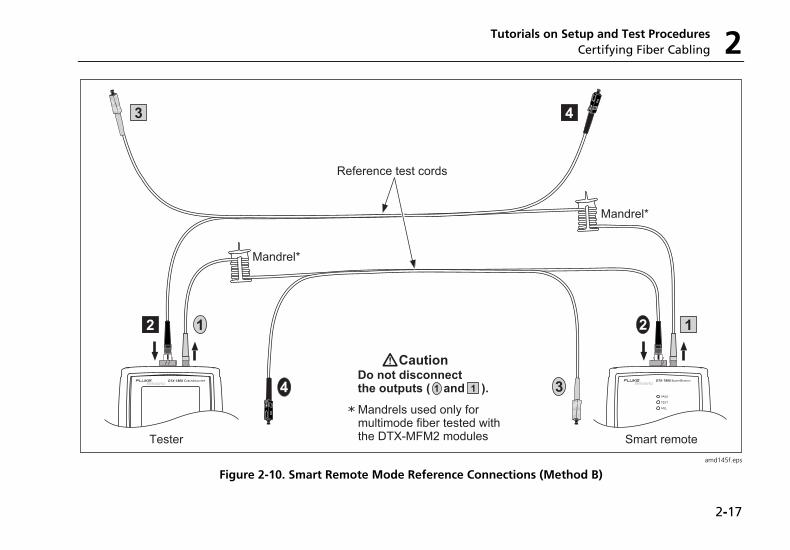
Tutorials on Setup and Test Procedures Certifying Fiber Cabling 2
2-17
amd145f.eps
Figure 2-10. Smart Remote Mode Reference Connections (Method B)
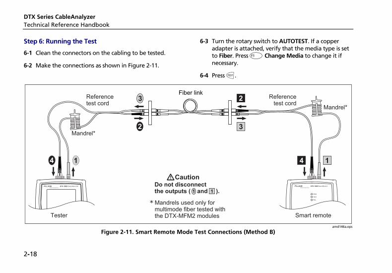
DTX Series CableAnalyzer Technical Reference Handbook
2-18
Step 6: Running the Test
6-1 Clean the connectors on the cabling to be tested.
6-2 Make the connections as shown in Figure 2-11.
6-3 Turn the rotary switch to AUTOTEST. If a copper adapter is attached, verify that the media type is set to Fiber. Press J Change Media to change it if necessary.
6-4 Press P.
amd146a.eps
Figure 2-11. Smart Remote Mode Test Connections (Method B)
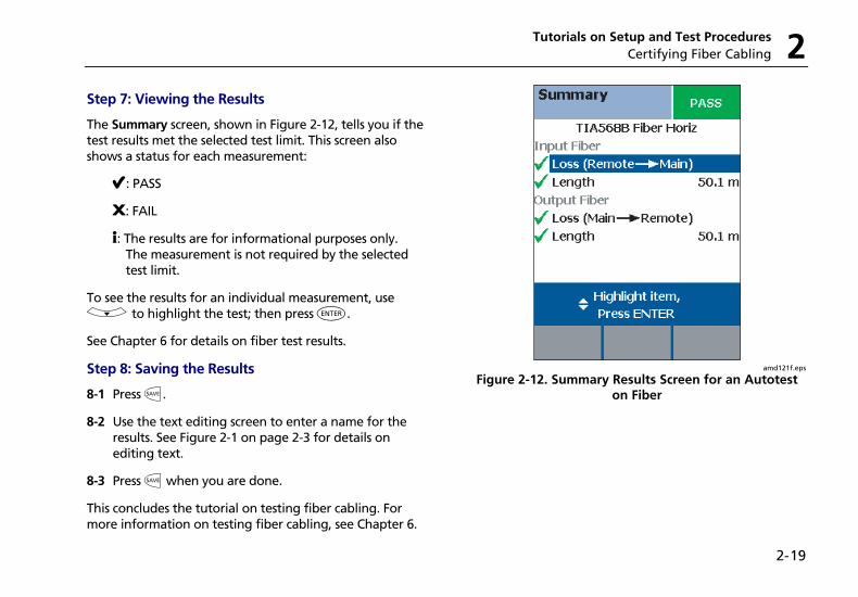
Tutorials on Setup and Test Procedures Certifying Fiber Cabling 2
2-19
Step 7: Viewing the Results
The Summary screen, shown in Figure 2-12, tells you if the test results met the selected test limit. This screen also shows a status for each measurement:
E: PASS
F: FAIL
i: The results are for informational purposes only. The measurement is not required by the selected test limit.
To see the results for an individual measurement, use D to highlight the test; then press H.
See Chapter 6 for details on fiber test results.
Step 8: Saving the Results
8-1 Press N.
8-2 Use the text editing screen to enter a name for the results. See Figure 2-1 on page 2-3 for details on editing text.
8-3 Press N when you are done.
This concludes the tutorial on testing fiber cabling. For more information on testing fiber cabling, see Chapter 6.
amd121f.eps
Figure 2-12. Summary Results Screen for an Autotest on Fiber
DTX Series CableAnalyzer Technical Reference Handbook
2-20
Using the Auto Increment and Sequential Cable ID Features The auto increment and sequential ID features generate cable IDs automatically. This frees you from having to enter IDs manually after each test.
These features are useful when you test installations with sequentially-numbered links.
When you use an ID from a list, the ID is marked with a “$”.
Note
The List feature lets you select IDs from a list created with LinkWare software and downloaded to the tester. See the LinkWare documentation for details.
Using the Auto Increment Feature
The auto increment feature increments the last character in the fiber ID you enter.
For example, if you save a test with the ID “A0”, the tester increments the ID as follows:
A0, A1, A2…A9, A10, A11…A99, A100, A101…
Consecutive digits increment from right to left, but other characters do not.
Letters increment through the alphabet shown on the text editing screen:
1A, 1B, 1C…1Y, 1Z, 1Ç…1Û, 1Ü, 1A
To use the auto increment ID feature:
1 Turn the rotary switch to SETUP.
2 Use D to highlight Instrument Settings; then press H.
3 Press H to select Cable ID Source.
4 D to highlight Auto Increment; then press H.
5 Run a test; then press N.
6 Enter an ID in the ID: box.
7 Press N again.
The next time you run a test and press N, the incremented cable ID appears in the ID box. Press N again to use the ID.
Tutorials on Setup and Test Procedures Using the Auto Increment and Sequential Cable ID Features 2
2-21
Creating a List of Sequential IDs
The tester includes templates for creating a list of sequential IDs. Three of these templates meet the ANSI/TIA/EIA-606-A standard for documenting cabling installations, as summarized in the next section. A fourth template lets you create your own ID pattern.
Letters and numbers in sequential IDs increment from right to left. The following characters are not incremented:
• Special characters: / # * - . , : [ ] space
• Characters that match between the start and stop IDs. For example if the start and stop IDs were ROOM1 and ROOM25, the characters “ROOM” would not increment.
For example, the following start and stop IDs could be used for testing the cabling in two rooms where each room has three cable drops:
Start ID: ROOM A DROP#1 Stop ID: ROOM B DROP#3
These IDs produce the following ID list:
ROOM A DROP#1 ROOM A DROP#2 ROOM A DROP#3 ROOM B DROP#1 ROOM B DROP#2 ROOM B DROP#3
DTX Series CableAnalyzer Technical Reference Handbook
2-22
The steps below guide you through creating a sequential ID list for the following scenario:
• You will test 12 cables in two patch panels: cables 1 through 6 in panel A and cables 1 through 6 in panel B.
• Both panels are located in telecommunications closet A on the third floor of the building.
Your IDs will follow the ANSI/TIA/EIA-606-A standard for horizontal links. See “About ANSI/TIA/EIA-606-A Cable IDs” on page 2-24 for details.
1 Turn the rotary switch to SETUP.
2 Use D to highlight Instrument Settings, then press H.
3 Press H to select Cable ID Source.
4 Use D to highlight Auto Sequence, then press H.
5 Use D to highlight Template, then press H.
6 Use A D to highlight Horizontal, then press H.
7 On the Auto Sequence screen, press J Default to transfer the default pattern into the START ID and STOP ID.
8 Use A to highlight Start ID; then press H.
9 Use JKL, BCAD, and H to change the default ID to 03A-A01.
Press N when you are done.
10 Use D to highlight Stop ID; then press H.
11 Use JKL, BCAD, and H to change the default ID to 03A-B06.
Press N when you are done.
12 Press L Sample List. You should see a list of 12 sequential fiber IDs: 03A-A01 through 03A-B06. If the tester beeps instead of showing the list, check your Start and Stop IDs for the problems listed below.
13 Press I to leave the sample list.
If the tester shows an error message, check your Start and Stop IDs for the problems listed below.
14 Press N when you are done setting up the list. The list is saved in the tester’s internal memory.
Tutorials on Setup and Test Procedures Using the Auto Increment and Sequential Cable ID Features 2
2-23
If the ID sequence is invalid, check the following:
• Verify that the types of characters in each position match between the start and stop IDs. For example, using the letter “O” as the third character in the Start ID and the number “0” as the third character in the Stop ID is not allowed.
• Verify that you are not using the characters / # * - . , : [ ] space or accented characters as incrementing characters. You may use these characters in IDs, but they must match between the Start and Stop IDs.
• Verify that the Start and Stop IDs have the same numbers of characters.
• Verify that the Stop ID is not sequentially greater than the Start ID. For example, using 25 as the Start ID and 10 as the Stop ID is not allowed.
• Verify that the Start and Stop IDs do not generate a sequence with more than 3000 IDs.
To use an ID from the auto sequence list:
1 Verify that the Cable ID Source in SETUP is set to Auto Sequence.
2 Run a test; then press N.
3 To scroll through the ID list, use AD. To scroll one page at a time, use BC.
4 Select an ID from the ID list; then press N again.
DTX Series CableAnalyzer Technical Reference Handbook
2-24
About ANSI/TIA/EIA-606-A Cable IDs
The following sections give basic examples of the 606-A IDs. For detailed information, including ID formats for other elements in cabling installations, contact the TIA to purchase a copy of the 606-A standard.
The examples use the following abbreviations:
• f = floor number
• s = telecom room letter
• a = patch panel letter
• n = For a horizontal link: port number For a backbone: backbone cable letter or number
• d = copper pair or fiber strand number in backbone cable
• b = building
Horizontal Link Identifier
Horizontal links run between telecommunications closets and work areas.
Format: fs-an
Example: 11C-D32
The link tested was on floor 11 in telecom room C, patch panel D, port 32.
Backbone Cable Identifier
Backbone cables run between telecommunication closets, usually on different floors.
Format: fs1/fs2-n.d
Example: 01B/5C-D.10
The cable tested is in the backbone cable that runs between floor 1, telecom room B and floor 5, telecom room C. The backbone cable is cable D. The cable or fiber tested is fiber 10 in backbone cable D.
Tutorials on Setup and Test Procedures Using the Auto Increment and Sequential Cable ID Features 2
2-25
Campus Cable Identifier
Campus cables are backbone cables that run between buildings.
Format: [b1-f s1]/[b2-fs2]-n.d
Example: LBRY-01A/AUD-01A-5.16
The cable tested is in the backbone cable that runs between the library (LBRY), floor 1, telecom room A and the auditorium (AUD), floor 1, telecom room A. The backbone cable is cable 5. The cable or fiber tested is number 16 in backbone cable 5.

DTX Series CableAnalyzer Technical Reference Handbook
2-26
3-1
Chapter 3 Certifying Twisted Pair Cabling
Setting the Reference The reference procedure sets a baseline for insertion loss, ELFEXT, and dc resistance measurements.
Run the tester’s reference procedure at the following times:
• When you want to use the tester with a different smart remote. You can reference the tester to two different smart remotes.
• Every 30 days. Doing so ensures maximum accuracy of test results.
You do not need to set the reference after changing link interface adapters.
Note
Turn on the tester and smart remote and let them sit for 1 minute before setting the reference. Set the reference only after the testers have reached an ambient temperature between 10 °C and 40 °C (50 °F and 104 °F).
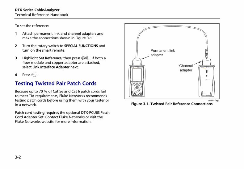
DTX Series CableAnalyzer Technical Reference Handbook
3-2
To set the reference:
1 Attach permanent link and channel adapters and make the connections shown in Figure 3-1.
2 Turn the rotary switch to SPECIAL FUNCTIONS and turn on the smart remote.
3 Highlight Set Reference; then press H. If both a fiber module and copper adapter are attached, select Link Interface Adapter next.
4 Press P.
Testing Twisted Pair Patch Cords Because up to 70 % of Cat 5e and Cat 6 patch cords fail to meet TIA requirements, Fluke Networks recommends testing patch cords before using them with your tester or in a network.
Patch cord testing requires the optional DTX-PCU6S Patch Cord Adapter Set. Contact Fluke Networks or visit the Fluke Networks website for more information.
PM06
Permanent link
adapter
Channel
adapter
TEST
LOW BATTERY
TONE
TALK
FAIL
TEST
PASS
TALKTALK
MONITOR
ENTER
TEST
SAVE
SPECIAL FUNCTIONS
SETUP
AUTO TESTSINGLE
TEST
EXIT
F1 F2 F3
amd41f.eps
Figure 3-1. Twisted Pair Reference Connections
Certifying Twisted Pair Cabling Twisted Pair Test Settings 3
3-3
Twisted Pair Test Settings Table 3-1 describes the settings that apply to twisted pair cabling tests.
To access the settings, turn the rotary switch to SETUP, use D to highlight Twisted Pair; then press H.
Table 3-1. Twisted Pair Test Settings
Setting Description
SETUP > Twisted Pair > Cable Type
Select a cable type appropriate for the type you will test. The cable types are organized by type and manufacturer. Selecting Custom lets you create a cable type. See Chapter 10 for details.
SETUP > Twisted Pair > Test Limit
Select the appropriate test limit for the job. Selecting Custom lets you create a test limit. See Chapter 10 for details.
SETUP > Twisted Pair > NVP
Nominal velocity of propagation, which is used with the measured propagation delay to determine cable length. The default value defined by the selected cable type represents the typical NVP for that cable type. You may enter a different value if necessary. To determine the actual value, change the NVP until the measured length matches the known length of a cable. Use a cable at least 30 m (100 ft) long. See Chapter 10.
Increasing the NVP increases measured length.
-continued-
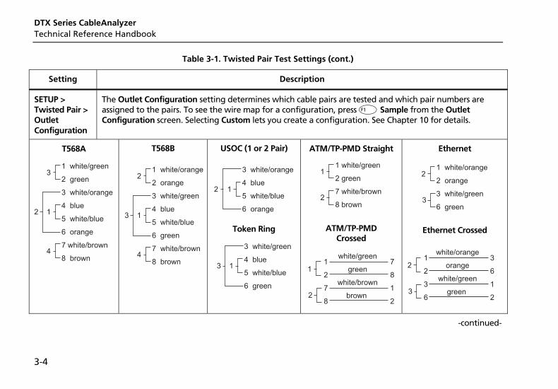
DTX Series CableAnalyzer Technical Reference Handbook
3-4
Table 3-1. Twisted Pair Test Settings (cont.)
Setting Description
SETUP > Twisted Pair > Outlet Configuration
The Outlet Configuration setting determines which cable pairs are tested and which pair numbers are assigned to the pairs. To see the wire map for a configuration, press J Sample from the Outlet Configuration screen. Selecting Custom lets you create a configuration. See Chapter 10 for details.
T568A
1 white/green
2 green
3 white/orange
4 blue
5 white/blue
6 orange
7 white/brown
8 brown
12
3
4
T568B
1 white/orange
2 orange
3 white/green
4 blue
5 white/blue
6 green
7 white/brown
8 brown
13
2
4
USOC (1 or 2 Pair)
3 white/orange
4 blue
5 white/blue
6 orange
12
Token Ring
3 white/green
4 blue
5 white/blue
6 green
13
ATM/TP-PMD Straight
1 white/green
2 green
7 white/brown
8 brown
1
2
ATM/TP-PMD Crossed
2
11
2
7
8
7
8
1
2
white/green
green
white/brown
brown
Ethernet
1 white/orange
2 orange
3 white/green
6 green3
2
Ethernet Crossed
3
21
2
3
6
3
6
1
2
white/orange
orange
white/green
green
-continued-
Certifying Twisted Pair Cabling Twisted Pair Test Settings 3
3-5
Table 3-1. Twisted Pair Test Settings (cont.)
Setting Description
SETUP > Instrument Settings > Store Plot Data
Standard: The tester displays and saves plot data for frequency-based tests such as NEXT, return loss, and attenuation. The tester saves data for the frequency range required by the selected test limit.
Extended: The tester saves data beyond the frequency range required by the selected test limit.
No: Plot data is not saved, which lets you save more results. Saved results show worst margins and worst values for each pair.
SPECIAL FUNCTIONS > Set Reference
The tester must be referenced to the smart remote the first time the two units are used together. You should also set the reference every 30 days. See “Setting the Reference” on page 3-1.
SETUP > Instrument Settings
Settings for saving tests
Cable ID Source, Current Folder, Result Storage Location (DTX-1800, DTX-1200), Operator, Site, and Company. See “Preparing to Save Tests” in Chapter 2.
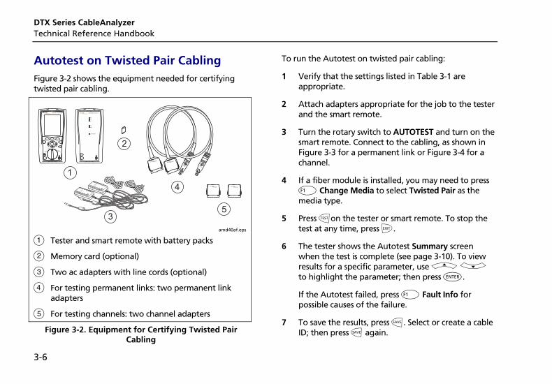
DTX Series CableAnalyzer Technical Reference Handbook
3-6
Autotest on Twisted Pair Cabling Figure 3-2 shows the equipment needed for certifying twisted pair cabling.
PM06
1
2
3
4
5
TEST
LOW BATTERY
TONE
TALK
FAIL
TEST
PASS
TALKTALK
MONITOR
ENTER
TEST
SAVE
SPECIAL FUNCTIONS
SETUP
AUTO TESTSINGLE
TEST
EXIT
F1 F2 F3
PM06
amd40af.eps
A Tester and smart remote with battery packs
B Memory card (optional)
C Two ac adapters with line cords (optional)
D For testing permanent links: two permanent link adapters
E For testing channels: two channel adapters
Figure 3-2. Equipment for Certifying Twisted Pair Cabling
To run the Autotest on twisted pair cabling:
1 Verify that the settings listed in Table 3-1 are appropriate.
2 Attach adapters appropriate for the job to the tester and the smart remote.
3 Turn the rotary switch to AUTOTEST and turn on the smart remote. Connect to the cabling, as shown in Figure 3-3 for a permanent link or Figure 3-4 for a channel.
4 If a fiber module is installed, you may need to press J Change Media to select Twisted Pair as the media type.
5 Press Pon the tester or smart remote. To stop the test at any time, press I.
6 The tester shows the Autotest Summary screen when the test is complete (see page 3-10). To view results for a specific parameter, use A D to highlight the parameter; then press H.
If the Autotest failed, press J Fault Info for possible causes of the failure.
7 To save the results, press N. Select or create a cable ID; then press N again.
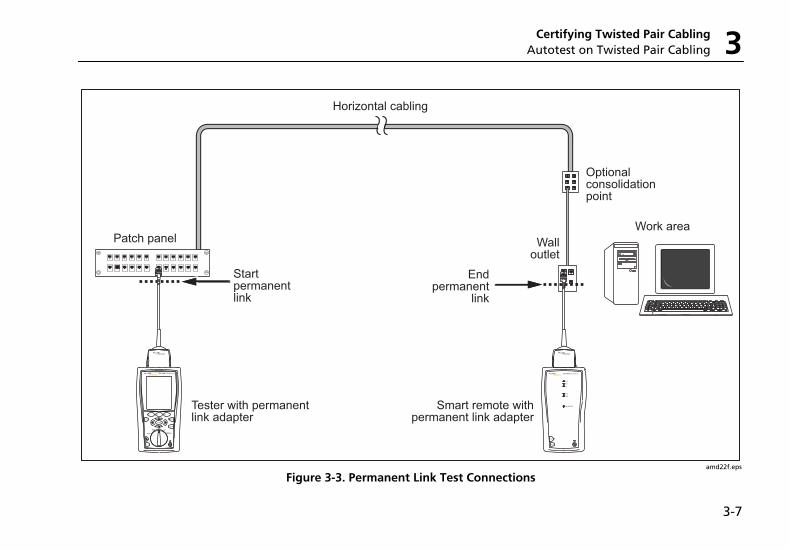
Certifying Twisted Pair Cabling Autotest on Twisted Pair Cabling 3
3-7
Work area
Optional consolidationpoint
Patch panel Wall outlet
Horizontal cabling
Endpermanent
link
Start permanentlink
Tester with permanentlink adapter
Smart remote withpermanent link adapter
TALK
MONITOR
ENTER
TEST
SAVE
SPECIAL FUNCTIONS
SETUP
AUTO TESTSINGLE
TEST
EXIT
F1 F2 F3
TEST
LOW BATTERY
TONE
TALK
FAIL
TEST
PASS
TALK
amd22f.eps
Figure 3-3. Permanent Link Test Connections

DTX Series CableAnalyzer Technical Reference Handbook
3-8
Work area
Optional consolidationpoint
Patchpanels
Hub or switch
Wall outlet
Horizontal cabling
Endchannel
Tester withchannel adapter
Smart remote withchannel adapter
Patch cordfrom PC
Patch cordfrom hub or
switch
Startchannel
TEST
LOW BATTERY
TONE
TALK
FAIL
TEST
PASS
TALKTALK
MONITOR
ENTER
TEST
SAVE
SPECIAL FUNCTIONS
SETUP
AUTO TESTSINGLE
TEST
EXIT
F1 F2 F3
amd21f.eps
Figure 3-4. Channel Test Connections
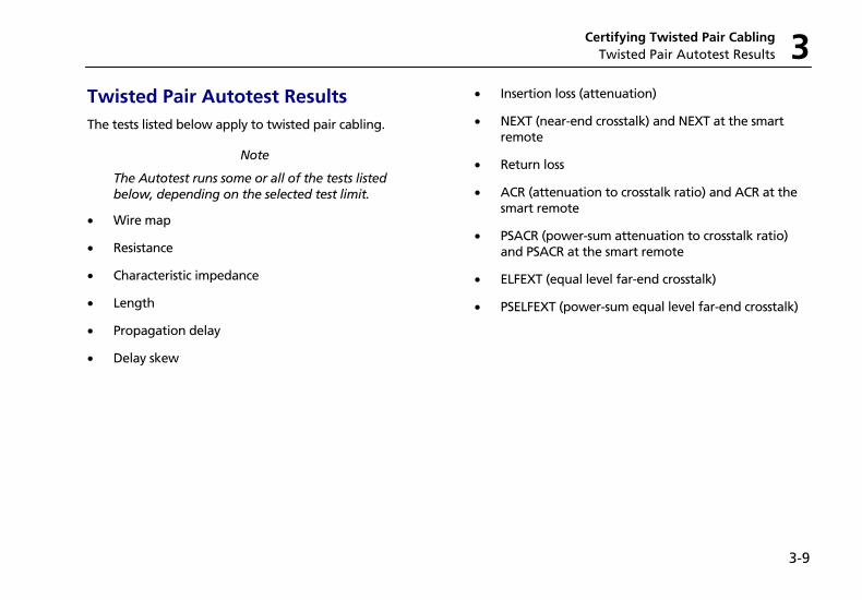
Certifying Twisted Pair Cabling Twisted Pair Autotest Results 3
3-9
Twisted Pair Autotest Results The tests listed below apply to twisted pair cabling.
Note
The Autotest runs some or all of the tests listed below, depending on the selected test limit.
• Wire map
• Resistance
• Characteristic impedance
• Length
• Propagation delay
• Delay skew
• Insertion loss (attenuation)
• NEXT (near-end crosstalk) and NEXT at the smart remote
• Return loss
• ACR (attenuation to crosstalk ratio) and ACR at the smart remote
• PSACR (power-sum attenuation to crosstalk ratio) and PSACR at the smart remote
• ELFEXT (equal level far-end crosstalk)
• PSELFEXT (power-sum equal level far-end crosstalk)
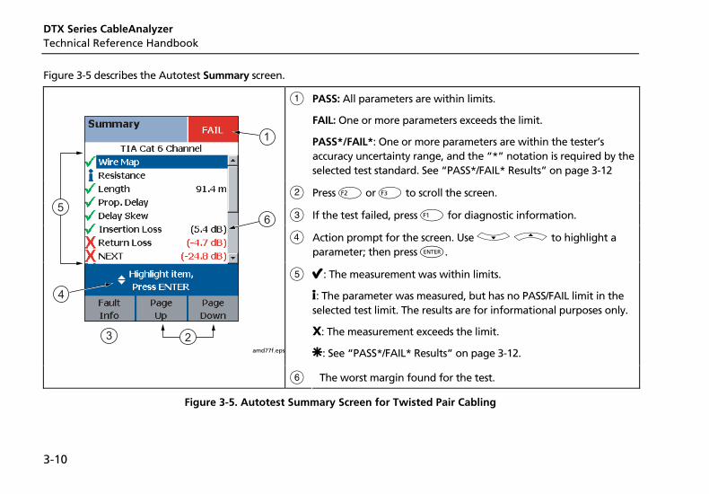
DTX Series CableAnalyzer Technical Reference Handbook
3-10
Figure 3-5 describes the Autotest Summary screen.
A PASS: All parameters are within limits.
FAIL: One or more parameters exceeds the limit.
PASS*/FAIL*: One or more parameters are within the tester’s accuracy uncertainty range, and the “*” notation is required by the selected test standard. See “PASS*/FAIL* Results” on page 3-12
B Press K or L to scroll the screen.
C If the test failed, press J for diagnostic information.
D Action prompt for the screen. Use D A to highlight a parameter; then press H.
E E: The measurement was within limits.
i: The parameter was measured, but has no PASS/FAIL limit in the selected test limit. The results are for informational purposes only.
X: The measurement exceeds the limit.
U: See “PASS*/FAIL* Results” on page 3-12.
amd77f.eps
F The worst margin found for the test.
Figure 3-5. Autotest Summary Screen for Twisted Pair Cabling
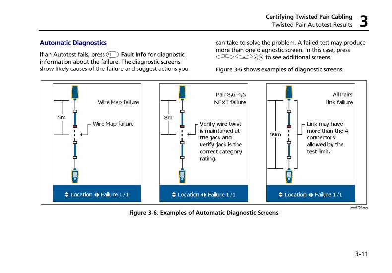
Certifying Twisted Pair Cabling Twisted Pair Autotest Results 3
3-11
Automatic Diagnostics
If an Autotest fails, press J Fault Info for diagnostic information about the failure. The diagnostic screens show likely causes of the failure and suggest actions you
can take to solve the problem. A failed test may produce more than one diagnostic screen. In this case, press ADBC to see additional screens.
Figure 3-6 shows examples of diagnostic screens.
amd75f.eps
Figure 3-6. Examples of Automatic Diagnostic Screens
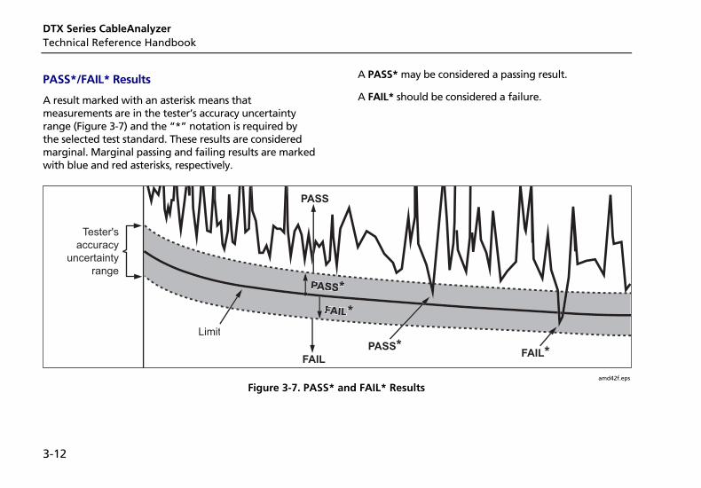
DTX Series CableAnalyzer Technical Reference Handbook
3-12
PASS*/FAIL* Results
A result marked with an asterisk means that measurements are in the tester’s accuracy uncertainty range (Figure 3-7) and the “*” notation is required by the selected test standard. These results are considered marginal. Marginal passing and failing results are marked with blue and red asterisks, respectively.
A PASS* may be considered a passing result.
A FAIL* should be considered a failure.
Limit
PASS*
PASS*
FAIL*
Tester's
accuracy
uncertainty
range
FAILFAIL*
PASS
amd42f.eps
Figure 3-7. PASS* and FAIL* Results
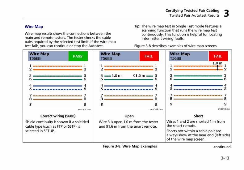
Certifying Twisted Pair Cabling Twisted Pair Autotest Results 3
3-13
Wire Map
Wire map results show the connections between the main and remote testers. The tester checks the cable pairs required by the selected test limit. If the wire map test fails, you can continue or stop the Autotest.
Tip: The wire map test in Single Test mode features a scanning function that runs the wire map test continuously. This function is helpful for locating intermittent wiring faults.
Figure 3-8 describes examples of wire map screens.
amd143i.bmp
amd144i.bmp
amd81i.bmp
Correct wiring (568B)
Shield continuity is shown if a shielded cable type (such as FTP or SSTP) is selected in SETUP.
Open
Wire 3 is open 1.0 m from the tester and 91.6 m from the smart remote.
Short
Wires 1 and 2 are shorted 1 m from the smart remote. Shorts not within a cable pair are always show at the near end (left side) of the wire map screen.
Figure 3-8. Wire Map Examples -continued-
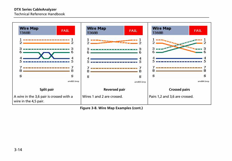
DTX Series CableAnalyzer Technical Reference Handbook
3-14
amd82i.bmp
amd83i.bmp
amd84i.bmp
Split pair
A wire in the 3,6 pair is crossed with a wire in the 4,5 pair.
Reversed pair
Wires 1 and 2 are crossed.
Crossed pairs
Pairs 1,2 and 3,6 are crossed.
Figure 3-8. Wire Map Examples (cont.)
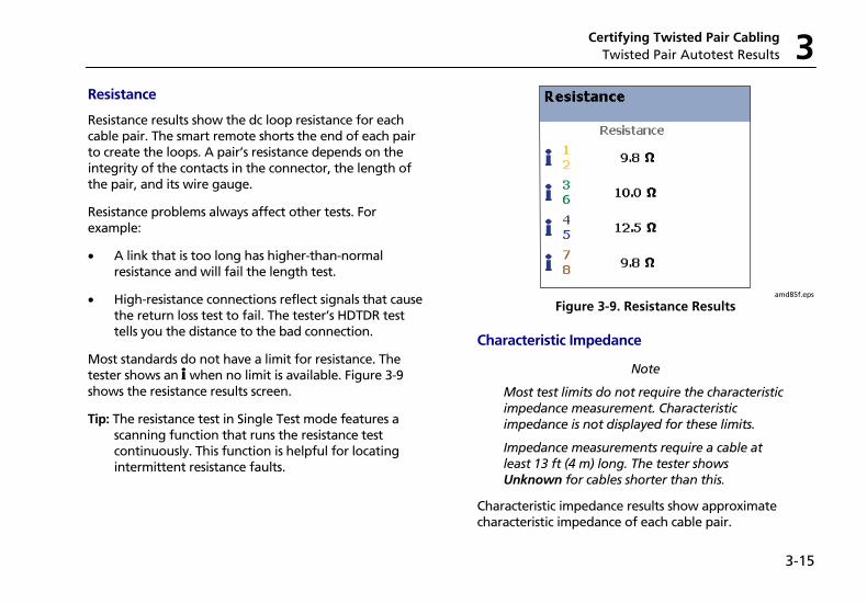
Certifying Twisted Pair Cabling Twisted Pair Autotest Results 3
3-15
Resistance
Resistance results show the dc loop resistance for each cable pair. The smart remote shorts the end of each pair to create the loops. A pair’s resistance depends on the integrity of the contacts in the connector, the length of the pair, and its wire gauge.
Resistance problems always affect other tests. For example:
• A link that is too long has higher-than-normal resistance and will fail the length test.
• High-resistance connections reflect signals that cause the return loss test to fail. The tester’s HDTDR test tells you the distance to the bad connection.
Most standards do not have a limit for resistance. The tester shows an i when no limit is available. Figure 3-9 shows the resistance results screen.
Tip: The resistance test in Single Test mode features a scanning function that runs the resistance test continuously. This function is helpful for locating intermittent resistance faults.
amd85f.eps
Figure 3-9. Resistance Results
Characteristic Impedance
Note
Most test limits do not require the characteristic impedance measurement. Characteristic impedance is not displayed for these limits.
Impedance measurements require a cable at least 13 ft (4 m) long. The tester shows Unknown for cables shorter than this.
Characteristic impedance results show approximate characteristic impedance of each cable pair.
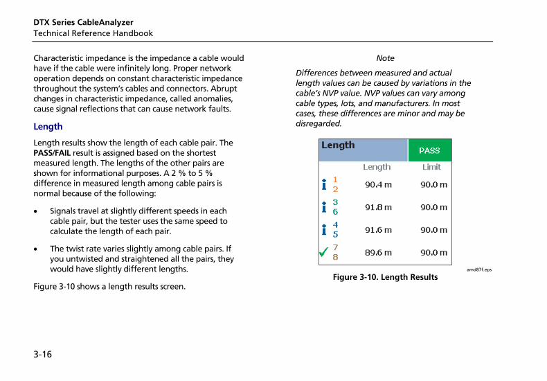
DTX Series CableAnalyzer Technical Reference Handbook
3-16
Characteristic impedance is the impedance a cable would have if the cable were infinitely long. Proper network operation depends on constant characteristic impedance throughout the system’s cables and connectors. Abrupt changes in characteristic impedance, called anomalies, cause signal reflections that can cause network faults.
Length
Length results show the length of each cable pair. The PASS/FAIL result is assigned based on the shortest measured length. The lengths of the other pairs are shown for informational purposes. A 2 % to 5 % difference in measured length among cable pairs is normal because of the following:
• Signals travel at slightly different speeds in each cable pair, but the tester uses the same speed to calculate the length of each pair.
• The twist rate varies slightly among cable pairs. If you untwisted and straightened all the pairs, they would have slightly different lengths.
Figure 3-10 shows a length results screen.
Note
Differences between measured and actual length values can be caused by variations in the cable’s NVP value. NVP values can vary among cable types, lots, and manufacturers. In most cases, these differences are minor and may be disregarded.
amd87f.eps
Figure 3-10. Length Results
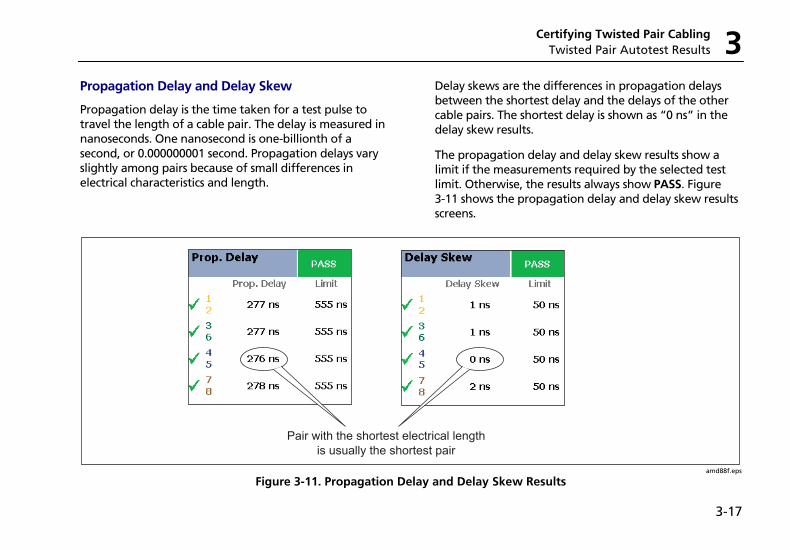
Certifying Twisted Pair Cabling Twisted Pair Autotest Results 3
3-17
Propagation Delay and Delay Skew
Propagation delay is the time taken for a test pulse to travel the length of a cable pair. The delay is measured in nanoseconds. One nanosecond is one-billionth of a second, or 0.000000001 second. Propagation delays vary slightly among pairs because of small differences in electrical characteristics and length.
Delay skews are the differences in propagation delays between the shortest delay and the delays of the other cable pairs. The shortest delay is shown as “0 ns” in the delay skew results.
The propagation delay and delay skew results show a limit if the measurements required by the selected test limit. Otherwise, the results always show PASS. Figure 3-11 shows the propagation delay and delay skew results screens.
Pair with the shortest electrical lengthis usually the shortest pair
amd88f.eps
Figure 3-11. Propagation Delay and Delay Skew Results
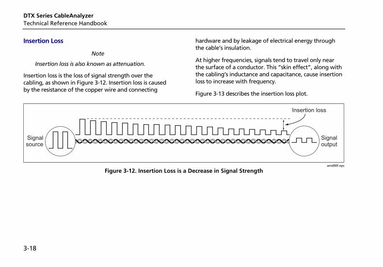
DTX Series CableAnalyzer Technical Reference Handbook
3-18
Insertion Loss
Note
Insertion loss is also known as attenuation.
Insertion loss is the loss of signal strength over the cabling, as shown in Figure 3-12. Insertion loss is caused by the resistance of the copper wire and connecting
hardware and by leakage of electrical energy through the cable’s insulation.
At higher frequencies, signals tend to travel only near the surface of a conductor. This “skin effect”, along with the cabling’s inductance and capacitance, cause insertion loss to increase with frequency.
Figure 3-13 describes the insertion loss plot.
Signalsource
Signaloutput
Insertion loss
amd90f.eps
Figure 3-12. Insertion Loss is a Decrease in Signal Strength
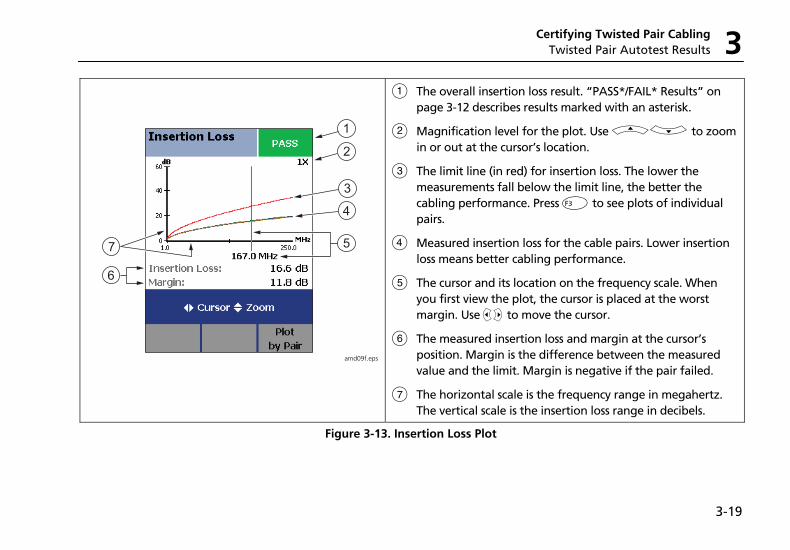
Certifying Twisted Pair Cabling Twisted Pair Autotest Results 3
3-19
1
2
3
4
5
6
7
amd09f.eps
A The overall insertion loss result. “PASS*/FAIL* Results” on page 3-12 describes results marked with an asterisk.
B Magnification level for the plot. Use AD to zoom in or out at the cursor’s location.
C The limit line (in red) for insertion loss. The lower the measurements fall below the limit line, the better the cabling performance. Press L to see plots of individual pairs.
D Measured insertion loss for the cable pairs. Lower insertion loss means better cabling performance.
E The cursor and its location on the frequency scale. When you first view the plot, the cursor is placed at the worst margin. Use BC to move the cursor.
F The measured insertion loss and margin at the cursor’s position. Margin is the difference between the measured value and the limit. Margin is negative if the pair failed.
G The horizontal scale is the frequency range in megahertz. The vertical scale is the insertion loss range in decibels.
Figure 3-13. Insertion Loss Plot
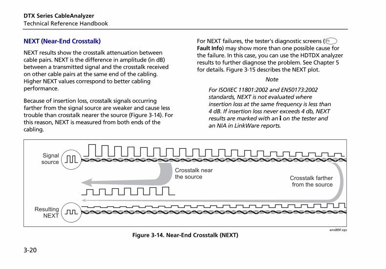
DTX Series CableAnalyzer Technical Reference Handbook
3-20
NEXT (Near-End Crosstalk)
NEXT results show the crosstalk attenuation between cable pairs. NEXT is the difference in amplitude (in dB) between a transmitted signal and the crosstalk received on other cable pairs at the same end of the cabling. Higher NEXT values correspond to better cabling performance.
Because of insertion loss, crosstalk signals occurring farther from the signal source are weaker and cause less trouble than crosstalk nearer the source (Figure 3-14). For this reason, NEXT is measured from both ends of the cabling.
For NEXT failures, the tester's diagnostic screens (J Fault Info) may show more than one possible cause for the failure. In this case, you can use the HDTDX analyzer results to further diagnose the problem. See Chapter 5 for details. Figure 3-15 describes the NEXT plot.
Note
For ISO/IEC 11801:2002 and EN50173:2002 standards, NEXT is not evaluated where insertion loss at the same frequency is less than 4 dB. If insertion loss never exceeds 4 db, NEXT results are marked with an i on the tester and an N/A in LinkWare reports.
Signalsource
ResultingNEXT
Crosstalk nearthe source Crosstalk farther
from the source
amd89f.eps
Figure 3-14. Near-End Crosstalk (NEXT)
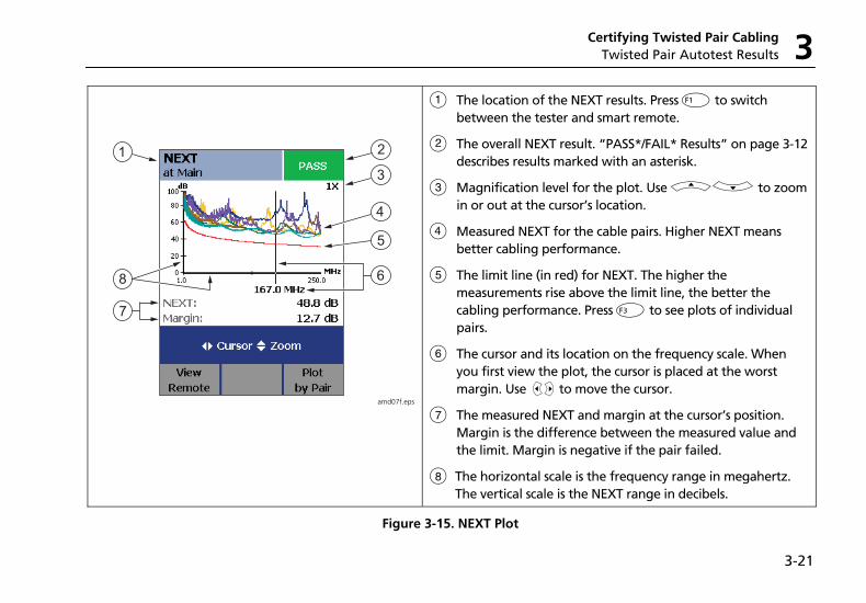
Certifying Twisted Pair Cabling Twisted Pair Autotest Results 3
3-21
1 2
3
4
5
6
7
8
amd07f.eps
A The location of the NEXT results. Press J to switch between the tester and smart remote.
B The overall NEXT result. “PASS*/FAIL* Results” on page 3-12 describes results marked with an asterisk.
C Magnification level for the plot. Use AD to zoom in or out at the cursor’s location.
D Measured NEXT for the cable pairs. Higher NEXT means better cabling performance.
E The limit line (in red) for NEXT. The higher the measurements rise above the limit line, the better the cabling performance. Press L to see plots of individual pairs.
F The cursor and its location on the frequency scale. When you first view the plot, the cursor is placed at the worst margin. Use BC to move the cursor.
G The measured NEXT and margin at the cursor’s position. Margin is the difference between the measured value and the limit. Margin is negative if the pair failed.
H The horizontal scale is the frequency range in megahertz. The vertical scale is the NEXT range in decibels.
Figure 3-15. NEXT Plot
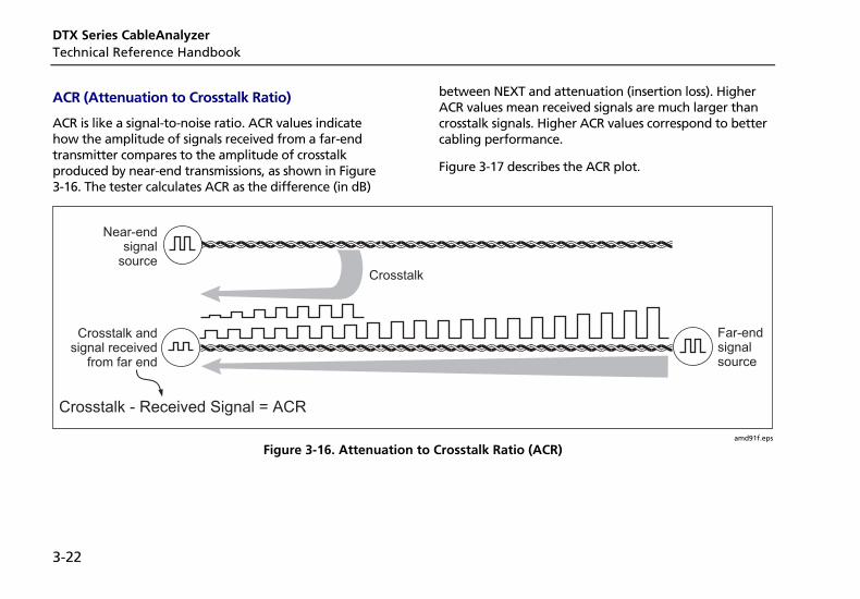
DTX Series CableAnalyzer Technical Reference Handbook
3-22
ACR (Attenuation to Crosstalk Ratio)
ACR is like a signal-to-noise ratio. ACR values indicate how the amplitude of signals received from a far-end transmitter compares to the amplitude of crosstalk produced by near-end transmissions, as shown in Figure 3-16. The tester calculates ACR as the difference (in dB)
between NEXT and attenuation (insertion loss). Higher ACR values mean received signals are much larger than crosstalk signals. Higher ACR values correspond to better cabling performance.
Figure 3-17 describes the ACR plot.
Far-endsignalsource
Crosstalk
Near-endsignal
source
Crosstalk - Received Signal = ACR
Crosstalk andsignal received
from far end
amd91f.eps
Figure 3-16. Attenuation to Crosstalk Ratio (ACR)

Certifying Twisted Pair Cabling Twisted Pair Autotest Results 3
3-23
1 2
3
4
5
6
7
8
amd11f.eps
A The location of the ACR results. Press J to switch between the tester and smart remote.
B The overall ACR result. “PASS*/FAIL* Results” on page 3-12 describes results marked with an asterisk.
C Magnification level for the plot. Use AD to zoom in or out at the cursor’s location.
D Measured ACR for the cable pairs. Higher ACR means better cabling performance.
E The limit line (in red) for ACR. The higher the measurements rise above the limit line, the better the cabling performance. Press L to see plots of individual pairs.
F The cursor and its location on the frequency scale. When you first view the plot, the cursor is placed at the worst margin. Use BC to move the cursor.
G The measured ACR and margin at the cursor’s position. Margin is the difference between the measured value and the limit. Margin is negative if the pair failed.
H The horizontal scale is the frequency range in megahertz. The vertical scale is the ACR range in decibels.
Figure 3-17. ACR Plot
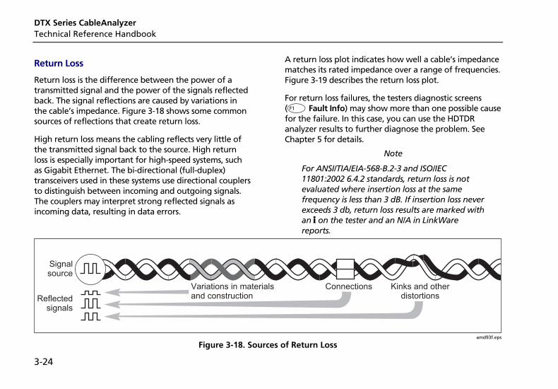
DTX Series CableAnalyzer Technical Reference Handbook
3-24
Return Loss
Return loss is the difference between the power of a transmitted signal and the power of the signals reflected back. The signal reflections are caused by variations in the cable’s impedance. Figure 3-18 shows some common sources of reflections that create return loss.
High return loss means the cabling reflects very little of the transmitted signal back to the source. High return loss is especially important for high-speed systems, such as Gigabit Ethernet. The bi-directional (full-duplex) transceivers used in these systems use directional couplers to distinguish between incoming and outgoing signals. The couplers may interpret strong reflected signals as incoming data, resulting in data errors.
A return loss plot indicates how well a cable’s impedance matches its rated impedance over a range of frequencies. Figure 3-19 describes the return loss plot.
For return loss failures, the testers diagnostic screens (J Fault Info) may show more than one possible cause for the failure. In this case, you can use the HDTDR analyzer results to further diagnose the problem. See Chapter 5 for details.
Note
For ANSI/TIA/EIA-568-B.2-3 and ISO/IEC 11801:2002 6.4.2 standards, return loss is not evaluated where insertion loss at the same frequency is less than 3 dB. If insertion loss never exceeds 3 db, return loss results are marked with an i on the tester and an N/A in LinkWare reports.
Signalsource
Kinks and otherdistortions
ConnectionsVariations in materialsand constructionReflected
signals
amd93f.eps
Figure 3-18. Sources of Return Loss
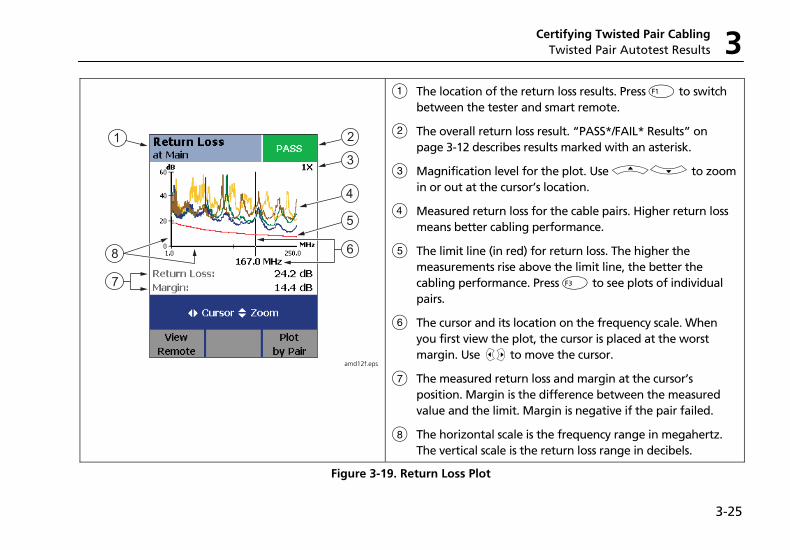
Certifying Twisted Pair Cabling Twisted Pair Autotest Results 3
3-25
1 2
3
4
5
6
7
8
amd12f.eps
A The location of the return loss results. Press J to switch between the tester and smart remote.
B The overall return loss result. “PASS*/FAIL* Results” on page 3-12 describes results marked with an asterisk.
C Magnification level for the plot. Use AD to zoom in or out at the cursor’s location.
D Measured return loss for the cable pairs. Higher return loss means better cabling performance.
E The limit line (in red) for return loss. The higher the measurements rise above the limit line, the better the cabling performance. Press L to see plots of individual pairs.
F The cursor and its location on the frequency scale. When you first view the plot, the cursor is placed at the worst margin. Use BC to move the cursor.
G The measured return loss and margin at the cursor’s position. Margin is the difference between the measured value and the limit. Margin is negative if the pair failed.
H The horizontal scale is the frequency range in megahertz. The vertical scale is the return loss range in decibels.
Figure 3-19. Return Loss Plot
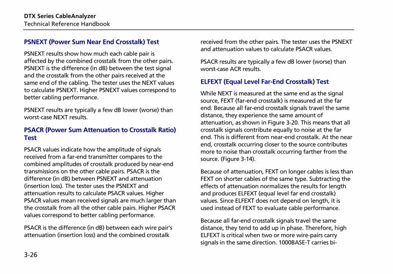
DTX Series CableAnalyzer Technical Reference Handbook
3-26
PSNEXT (Power Sum Near End Crosstalk) Test
PSNEXT results show how much each cable pair is affected by the combined crosstalk from the other pairs. PSNEXT is the difference (in dB) between the test signal and the crosstalk from the other pairs received at the same end of the cabling. The tester uses the NEXT values to calculate PSNEXT. Higher PSNEXT values correspond to better cabling performance.
PSNEXT results are typically a few dB lower (worse) than worst-case NEXT results.
PSACR (Power Sum Attenuation to Crosstalk Ratio) Test
PSACR values indicate how the amplitude of signals received from a far-end transmitter compares to the combined amplitudes of crosstalk produced by near-end transmissions on the other cable pairs. PSACR is the difference (in dB) between PSNEXT and attenuation (insertion loss). The tester uses the PSNEXT and attenuation results to calculate PSACR values. Higher PSACR values mean received signals are much larger than the crosstalk from all the other cable pairs. Higher PSACR values correspond to better cabling performance.
PSACR is the difference (in dB) between each wire pair’s attenuation (insertion loss) and the combined crosstalk
received from the other pairs. The tester uses the PSNEXT and attenuation values to calculate PSACR values.
PSACR results are typically a few dB lower (worse) than worst-case ACR results.
ELFEXT (Equal Level Far-End Crosstalk) Test
While NEXT is measured at the same end as the signal source, FEXT (far-end crosstalk) is measured at the far end. Because all far-end crosstalk signals travel the same distance, they experience the same amount of attenuation, as shown in Figure 3-20. This means that all crosstalk signals contribute equally to noise at the far end. This is different from near-end crosstalk. At the near end, crosstalk occurring closer to the source contributes more to noise than crosstalk occurring farther from the source. (Figure 3-14).
Because of attenuation, FEXT on longer cables is less than FEXT on shorter cables of the same type. Subtracting the effects of attenuation normalizes the results for length and produces ELFEXT (equal level far end crosstalk) values. Since ELFEXT does not depend on length, it is used instead of FEXT to evaluate cable performance.
Because all far-end crosstalk signals travel the same distance, they tend to add up in phase. Therefore, high ELFEXT is critical when two or more wire-pairs carry signals in the same direction. 1000BASE-T carries bi-
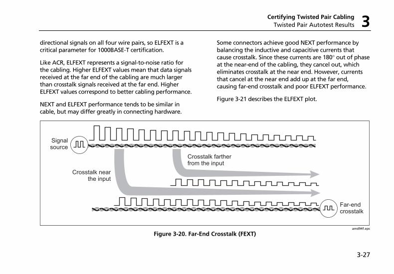
Certifying Twisted Pair Cabling Twisted Pair Autotest Results 3
3-27
directional signals on all four wire pairs, so ELFEXT is a critical parameter for 1000BASE-T certification.
Like ACR, ELFEXT represents a signal-to-noise ratio for the cabling. Higher ELFEXT values mean that data signals received at the far end of the cabling are much larger than crosstalk signals received at the far end. Higher ELFEXT values correspond to better cabling performance.
NEXT and ELFEXT performance tends to be similar in cable, but may differ greatly in connecting hardware.
Some connectors achieve good NEXT performance by balancing the inductive and capacitive currents that cause crosstalk. Since these currents are 180° out of phase at the near-end of the cabling, they cancel out, which eliminates crosstalk at the near end. However, currents that cancel at the near end add up at the far end, causing far-end crosstalk and poor ELFEXT performance.
Figure 3-21 describes the ELFEXT plot.
Far-endcrosstalk
Signalsource
Crosstalk nearthe input
Crosstalk fartherfrom the input
amd94f.eps
Figure 3-20. Far-End Crosstalk (FEXT)
DTX Series CableAnalyzer Technical Reference Handbook
3-28
1 2
3
4
5
6
7
8
amd13f.eps
A The location of the ELFEXT results. Press J to switch between the tester and smart remote.
B The overall ELFEXT result. “PASS*/FAIL* Results” on page 3-12 describes results marked with an asterisk.
C Magnification level for the plot. Use AD to zoom in or out at the cursor’s location.
D Measured ELFEXT for the cable pairs. Higher ELFEXT means better cabling performance.
E The limit line (in red) for ELFEXT. The higher the measurements rise above the limit line, the better the cabling performance. Press L to see plots of individual pairs.
F The cursor and its location on the frequency scale. When you first view the plot, the cursor is placed at the worst margin. Use BC to move the cursor.
G The measured ELFEXT and margin at the cursor’s position. Margin is the difference between the measured value and the limit. Margin is negative if the pair failed.
H The horizontal scale is the frequency range in megahertz. The vertical scale is the ELFEXT range in decibels.
Figure 3-21. ELFEXT Plot
Certifying Twisted Pair Cabling Running Single Tests 3
3-29
PSELFEXT Test
PSELFEXT results show how much the far end of each cable pair is affected by the combined far-end crosstalk from the other pairs. PSELFEXT is the difference (in dB) between the test signal and the crosstalk from the other pairs received at the far end of the cabling. The tester uses the ELFEXT values to calculate PSELFEXT. Higher PSELFEXT values correspond to better cabling performance.
PSELFEXT results are typically a few dB lower than worst-case FEXT results.
Running Single Tests The tester’s single test mode (SINGLE TEST on the rotary switch) lets you run individual tests for isolating cabling failures and quickly testing repairs. You can run some single tests without a remote. Table 3-2 shows which tests require a smart remote.
Single tests use the selected test limit to produce a PASS/FAIL result for the test. Each single test also produces results for other measurements. For example, the wire map test also produces propagation delay and delay skew results. To see these results, press I when the single test is finished; then press K View Results.
To save a single test, press N, select or create a cable ID; then press N again.
DTX Series CableAnalyzer Technical Reference Handbook
3-30
Table 3-2. Smart Remote Requirements for Twisted Pair Single Tests
Test Smart Remote Requirements*
HDTDX analyzer Recommended. Without a smart remote, results for short cables may be unreliable.
HDTDR analyzer Optional. Without a smart remote, the plot shows large reflections at the end of the cabling.
Wire Map Recommended. Without a remote some faults, such as split pairs and opens at the far-end connector, cannot be detected.
Resistance Optional.
Impedance Optional. Test is available only for limits that require the impedance measurement.
Length Optional.
Propagation Delay Optional.
Delay Skew Optional.
Insertion Loss Required.
NEXT/PSNEXT Recommended. The NEXT test fails unless the end of the cabling is properly terminated with a remote or resistors.
ELFEXT/PSELFEXT Required.
ACR/PSACR Required.
Return Loss Recommended. The return loss test fails unless the end of the cabling is properly terminated with a remote or resistors.
* Note: If a remote is not required for a test, the test runs without activating the toner when no remote is detected.
Certifying Twisted Pair Cabling Monitoring Impulse Noise 3
3-31
Monitoring Impulse Noise Impulse noise is electrical noise generated by fluorescent lights, electric motors, electric heaters and air conditioners, photocopiers, refrigerators, microwave ovens, and other electric devices. Active links in the same pathway can also cause noise.
Noise distorts the shape of digital signals, as shown in Figure 3-22. Too much noise can cause transmission errors, resulting in poor network performance.
The impulse noise test lets you monitor noise on inactive twisted pair cabling to determine if the noise may affect network operation.
Receivedsignalsdistortedby noise
Signalsource
LAN cabling
amd95f.eps
Figure 3-22. Causes and Effects of Noise
DTX Series CableAnalyzer Technical Reference Handbook
3-32
The test takes noise voltage samples every second on pair 3, 6. The test produces a PASS/FAIL result if the selected standard specifies a noise limit.
Note
Monitoring impulse noise without a smart remote may produce unreliable test results.
To monitor impulse noise:
1 Attach twisted pair link interface adapters to the tester and smart remote.
2 Turn the rotary switch to MONITOR and turn on the smart remote; then connect to the testers to the ends of the cabling.
3 Press P.
To adjust the noise threshold, press LStop; then use A D to change the value. Press P to resume testing.
Tip: Fluke Networks recommends a noise threshold of 30 mV with an average pulse rate below 0.01/sec for testing 1000BASE-T (Gigabit Ethernet) cabling.
To stop the test at any time, press I.
Note
If you disconnect the tester and smart remote during the impulse noise test, it takes several minutes for the remote to stop testing.
Figure 3-23 describes the impulse noise test results.
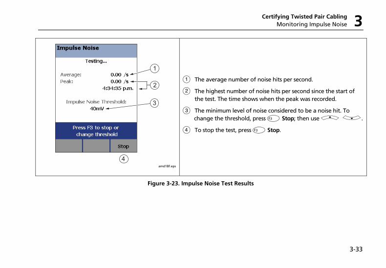
Certifying Twisted Pair Cabling Monitoring Impulse Noise 3
3-33
1
2
4
3
amd18f.eps
A The average number of noise hits per second.
B The highest number of noise hits per second since the start of the test. The time shows when the peak was recorded.
C The minimum level of noise considered to be a noise hit. To change the threshold, press L Stop; then use A D.
D To stop the test, press L Stop.
Figure 3-23. Impulse Noise Test Results
DTX Series CableAnalyzer Technical Reference Handbook
3-34
Using the Tone Generator The tone generator on the tester and smart remote produces a distinct signal for locating cables and jacks with a tone probe such as a Fluke Networks IntelliTone probe. The tone probe converts the toner’s signal to audible tones that get louder as you get closer to the cable or jack transmitting the signal.
The tone generator also activates a sleeping or powered-down tester or smart remote connected to the other end of the cabling.
Note
The tone generator does not generate the IntelliTone signal.
To use the tone generator:
1 Attach a twisted pair adapter to the tester or smart remote.
2 Connect the tester or smart remote to the cabling as shown in Figure 3-24.
3 To turn on the tester’s toner, turn the rotary switch to AUTOTEST or SINGLE TEST; then press P.
To turn on the smart remote’s toner, press P.
4 Use a tone probe to locate the cable or jack transmitting the tone.
Note
The toner's signal may not be detectable along shielded cable, but can be detected at a patch panel or outlet.
5 To start the test selected on the tester, connect the far-end unit to the cabling.
To turn off the tester’s toner, press I.
To turn off the smart remote’s toner, press P.
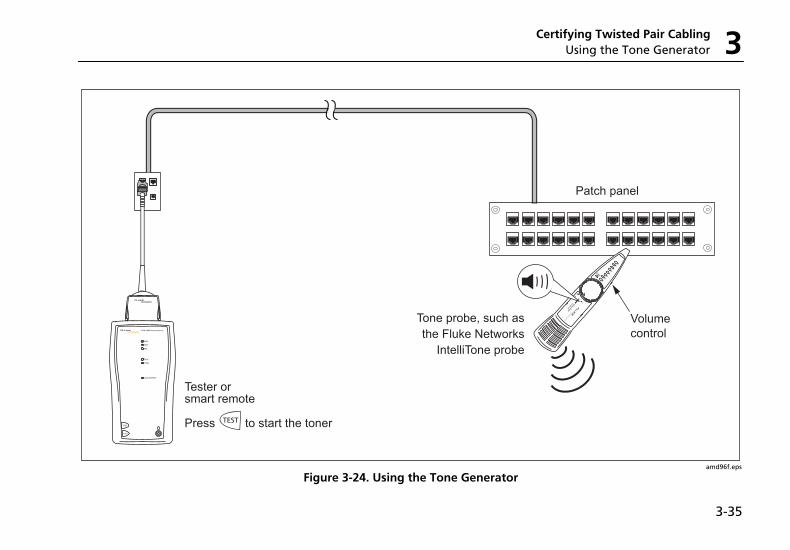
Certifying Twisted Pair Cabling Using the Tone Generator 3
3-35
INTELLITONE
INTELLITONE
200 PROBE
100 PROBE
Volume
control
Patch panel
Tester orsmart remote
TEST
LOW BATTERY
TONE
TALK
FAIL
TEST
PASS
TALK
Press to start the toner
Tone probe, such as
the Fluke Networks
IntelliTone probe
amd96f.eps
Figure 3-24. Using the Tone Generator

DTX Series CableAnalyzer Technical Reference Handbook
3-36
4-1
Chapter 4 Certifying Coaxial Cabling
Certifying coaxial cabling requires the optional DTX-COAX coaxial adapters.
Setting the Reference The reference procedure sets a baseline for insertion loss and resistance measurements.
Run the tester’s reference procedure at the following times:
• When you want to use the tester with a different smart remote. You can reference the tester to two different smart remotes.
• Every 30 days. Doing so ensures maximum accuracy of test results.
You do not need to set the reference after changing link interface adapters.
Note
Turn on the tester and let it sit for 1 minute before setting the reference. Set the reference only after the testers have reached an ambient temperature between 10 °C and 40 °C (50 °F and 104 °F).
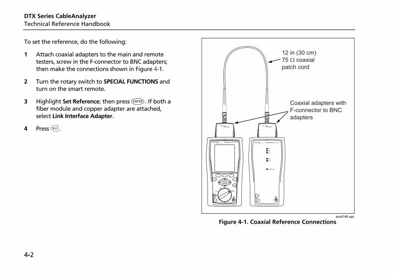
DTX Series CableAnalyzer Technical Reference Handbook
4-2
To set the reference, do the following:
1 Attach coaxial adapters to the main and remote testers, screw in the F-connector to BNC adapters; then make the connections shown in Figure 4-1.
2 Turn the rotary switch to SPECIAL FUNCTIONS and turn on the smart remote.
3 Highlight Set Reference; then press H. If both a fiber module and copper adapter are attached, select Link Interface Adapter.
4 Press P.
TEST
LOW BATTERY
TONE
TALK
FAIL
TEST
PASS
TALKTALK
MONITOR
ENTER
TEST
SAVE
SPECIALFUNCTIONS
SETUP
AUTOTESTSINGLE
TEST
EXIT
F1 F2 F3
amd140.eps
Figure 4-1. Coaxial Reference Connections
Certifying Coaxial Cabling Coaxial Test Settings 4
4-3
Coaxial Test Settings Table 4-1 describes the settings that apply to coaxial cabling tests.
To access the settings, turn the rotary switch to SETUP, use D to highlight Coax; then press H.
Table 4-1. Coaxial Cable Test Settings
Setting Description
SETUP > Coaxial > Cable Type
Select a cable type appropriate for the type you will test. The cable types are organized by type and manufacturer. Selecting Custom lets you create a cable type. See Chapter 10 for details.
SETUP > Coaxial > Test Limit
Select the appropriate test limit for the job. Selecting Custom lets you create a test limit. See Chapter 10 for details.
SETUP > Coaxial > NVP
Nominal velocity of propagation, which is used with the measured propagation delay to determine cable length. The default value defined by the selected cable type represents the typical NVP for that cable type. You may enter a different value if necessary. To determine the actual value, change the NVP until the measured length matches the known length of a cable. Use a cable at least 30 m (100 ft) long. See Chapter 10.
Increasing the NVP increases measured length.
-continued-
DTX Series CableAnalyzer Technical Reference Handbook
4-4
Table 4-1. Coaxial Cable Test Settings (cont.)
Setting Description
SETUP > Instrument Settings > Store Plot Data
Standard: The tester displays and saves plot data for insertion loss. The tester saves data for the frequency range required by the selected test limit.
Extended: The tester saves data beyond the frequency range required by the selected test limit.
No: Plot data is not saved, which lets you save more results. Saved results show only worst margins and worst values for each pair.
SPECIAL FUNCTIONS > Set Reference
The tester must be referenced to the smart remote the first time the two units are used together. You should also set the reference every 30 days. See “Setting the Reference” on page 4-1.
Settings for saving tests Cable ID Source, Current Folder, Result Storage Location (DTX-1800, DTX-1200), Operator, Site, and Company. See “Preparing to Save Tests” in Chapter 2.
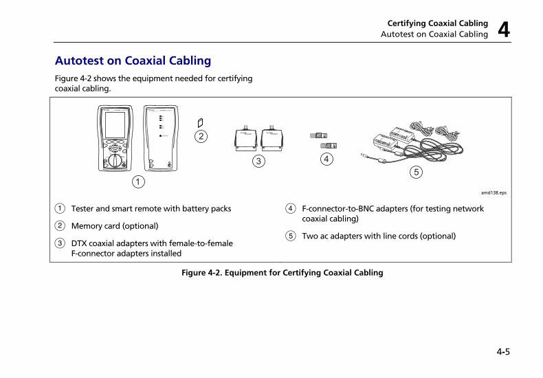
Certifying Coaxial Cabling Autotest on Coaxial Cabling 4
4-5
Autotest on Coaxial Cabling Figure 4-2 shows the equipment needed for certifying coaxial cabling.
1
2
3 4TEST
LOW BATTERY
TONE
TALK
FAIL
TEST
PASS
TALKTALK
MONITOR
ENTER
TEST
SAVE
SPECIALFUNCTIONS
SETUP
AUTOTESTSINGLE
TEST
EXIT
F1 F2 F3
5
amd138.eps
A Tester and smart remote with battery packs
B Memory card (optional)
C DTX coaxial adapters with female-to-female F-connector adapters installed
D F-connector-to-BNC adapters (for testing network coaxial cabling)
E Two ac adapters with line cords (optional)
Figure 4-2. Equipment for Certifying Coaxial Cabling
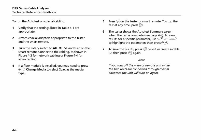
DTX Series CableAnalyzer Technical Reference Handbook
4-6
To run the Autotest on coaxial cabling:
1 Verify that the settings listed in Table 4-1 are appropriate.
2 Attach coaxial adapters appropriate to the tester and the smart remote.
3 Turn the rotary switch to AUTOTEST and turn on the smart remote. Connect to the cabling, as shown in Figure 4-3 for network cabling or Figure 4-4 for video cabling.
4 If a fiber module is installed, you may need to press J Change Media to select Coax as the media type.
5 Press Pon the tester or smart remote. To stop the test at any time, press I.
6 The tester shows the Autotest Summary screen when the test is complete (see page 4-9). To view results for a specific parameter, use A D to highlight the parameter; then press H.
7 To save the results, press N. Select or create a cable ID; then press N again.
Note
If you turn off the main or remote unit while the two units are connected through coaxial adapters, the unit will turn on again.
Certifying Coaxial Cabling Autotest on Coaxial Cabling 4
4-7
TALK
MONITOR
ENTER
TEST
SAVE
SPECIALFUNCTIONS
SETUP
AUTOTESTSINGLE
TEST
EXIT
F1 F2 F3
TEST
LOW BATTERY
TONE
TALK
FAIL
TEST
PASS
TALK
amd139.eps
Figure 4-3. Coaxial Network Cabling Test Connections
DTX Series CableAnalyzer Technical Reference Handbook
4-8
Female to femaleF-connector adapter
Tester with coaxialadapter
Smart remote withcoaxial adapter
TALK
MONITOR
ENTER
TEST
SAVE
SPECIAL FUNCTIONS
SETUP
AUTO TESTSINGLE
TEST
EXIT
F1 F2 F3
Connection tocoaxial cabling
Female to femaleF-connector adapter
TEST
LOW BATTERY
TONE
TALK
FAIL
TEST
PASS
TALK
Walloutlet
amd142.eps
Figure 4-4. Coaxial Video Cabling Test Connections
Certifying Coaxial Cabling Coaxial Autotest Results 4
4-9
Coaxial Autotest Results Figure 4-5 describes the Autotest Summary screen, which lists the tests that apply to coaxial cabling.
Note
The Autotest runs some or all of the tests shown in Figure 4-5, depending on the selected test limit.
amd141f.eps
A PASS: All parameters are within limits.
FAIL: One or more parameters exceeds the limit.
B E: The test passed.
i: The parameter was measured, but has no PASS/FAIL limit in the selected test limit.
X: The test failed.
C The worst margin found for the test.
Figure 4-5. Autotest Results for Coaxial Cabling
DTX Series CableAnalyzer Technical Reference Handbook
4-10
HDTDR Analyzer
The HDTDR (High-Definition Time Domain Reflectometry) analyzer plots the locations and magnitudes of reflections caused by impedance anomalies. See Chapter 5.
Resistance
Resistance results show the dc loop resistance for the center conductor and shield. The smart remote shorts the conductor and shield to create the loop.
Most standards do not have a limit for resistance. The tester shows an i when no limit is available.
Tip: The resistance test in Single Test mode features a scanning function that runs the resistance test continuously. This function is helpful for locating intermittent faults.
Impedance
Note
Impedance measurements require a cable at least 13 ft (4 m) long. The tester shows Unknown for cables shorter than this.
Impedance results show the approximate characteristic impedance of the cable at a point approximately 13 ft (4 m) from the tester.
Characteristic impedance is the impedance a cable would have if the cable were infinitely long. Good cabling has relatively constant characteristic impedance throughout the cable and connectors.
Changes in impedance cause signal reflections in cabling. In computer networks, signal reflections can cause network faults. In video systems, reflections can cause poor reception.
Certifying Coaxial Cabling Running Single Tests 4
4-11
Length
Length results show the length of the cabling.
Note
Differences between measured and actual length values can be caused by variations in the cable’s NVP value. NVP values can vary among cable types, lots, and manufacturers. In most cases, these differences are minor and may be disregarded.
Propagation Delay
Propagation delay is the time taken for a test pulse to travel the length of the cabling. The delay is measured in nanoseconds. One nanosecond is one-billionth of a second, or 0.000000001 second.
Insertion Loss
Insertion loss is the loss of signal strength over the cabling. Insertion loss is caused by the resistance of the copper wire and connecting hardware and by leakage of electrical energy through the cable’s insulation.
At higher frequencies, signals tend to travel only near the surface of a conductor. This “skin effect”, along with the cabling’s inductance and capacitance, cause insertion loss to increase with frequency.
Running Single Tests The tester’s single test mode (SINGLE TEST on the rotary switch) lets you run individual tests for isolating cabling failures and quickly testing repairs. You can run some single tests without a remote. Table 4-2 shows which tests require a smart remote.
Single tests use the selected test limit to produce a PASS/FAIL result for the test.
To save a single test, press N, select or create a cable ID; then press N again.
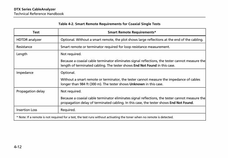
DTX Series CableAnalyzer Technical Reference Handbook
4-12
Table 4-2. Smart Remote Requirements for Coaxial Single Tests
Test Smart Remote Requirements*
HDTDR analyzer Optional. Without a smart remote, the plot shows large reflections at the end of the cabling.
Resistance Smart remote or terminator required for loop resistance measurement.
Length Not required.
Because a coaxial cable terminator eliminates signal reflections, the tester cannot measure the length of terminated cabling. The tester shows End Not Found in this case.
Impedance Optional.
Without a smart remote or terminator, the tester cannot measure the impedance of cables longer than 984 ft (300 m). The tester shows Unknown in this case.
Propagation delay Not required.
Because a coaxial cable terminator eliminates signal reflections, the tester cannot measure the propagation delay of terminated cabling. In this case, the tester shows End Not Found.
Insertion Loss Required.
* Note: If a remote is not required for a test, the test runs without activating the toner when no remote is detected.
5-1
Chapter 5 Diagnosing Copper Cabling Faults
Using the Automatic Diagnostics The DTX Series testers helps you isolate cabling faults by automatically diagnosing Autotest failures. For twisted pair tests, press J Fault Info after a failed Autotest to see information about the location and likely cause of the fault.
Avoiding Tester-Induced Failures Some test failures can be avoided if the tester is properly maintained and configured. To keep your tester in top condition, follow these guidelines:
• Keep the tester’s software current. The latest software is available on the Fluke Networks website. See Chapter 12 for details on installing updates.
• Set the reference for the twisted pair adapters every 30 days. See Chapter 3 for details.
• Run the self test before going to the job site. See Chapter 1 for details.
• Be sure to select the correct test standard and cable type for the job.
• Send the testers to a Fluke Networks service center every 12 months for factory calibration.
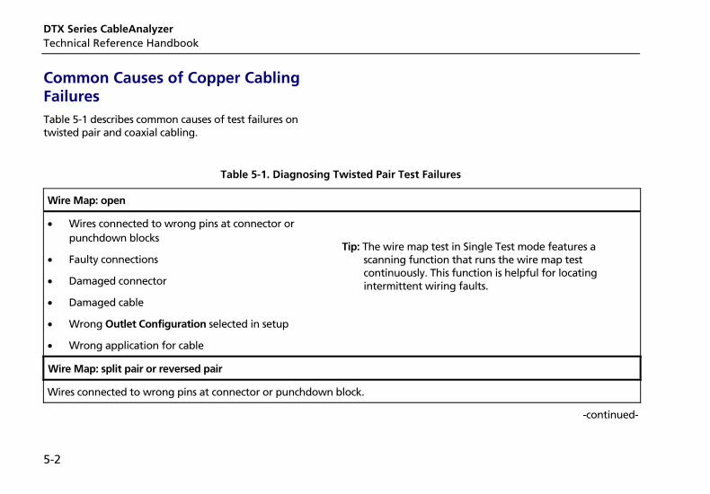
DTX Series CableAnalyzer Technical Reference Handbook
5-2
Common Causes of Copper Cabling Failures Table 5-1 describes common causes of test failures on twisted pair and coaxial cabling.
Table 5-1. Diagnosing Twisted Pair Test Failures
Wire Map: open
• Wires connected to wrong pins at connector or punchdown blocks
• Faulty connections
• Damaged connector
• Damaged cable
• Wrong Outlet Configuration selected in setup
• Wrong application for cable
Tip: The wire map test in Single Test mode features a scanning function that runs the wire map test continuously. This function is helpful for locating intermittent wiring faults.
Wire Map: split pair or reversed pair
Wires connected to wrong pins at connector or punchdown block.
-continued-
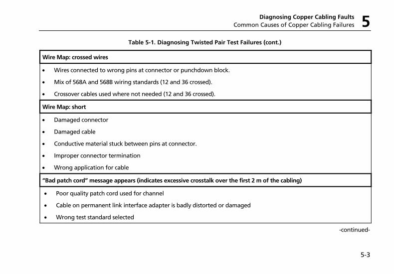
Diagnosing Copper Cabling Faults Common Causes of Copper Cabling Failures 5
5-3
Table 5-1. Diagnosing Twisted Pair Test Failures (cont.)
Wire Map: crossed wires
• Wires connected to wrong pins at connector or punchdown block.
• Mix of 568A and 568B wiring standards (12 and 36 crossed).
• Crossover cables used where not needed (12 and 36 crossed).
Wire Map: short
• Damaged connector
• Damaged cable
• Conductive material stuck between pins at connector.
• Improper connector termination
• Wrong application for cable
“Bad patch cord” message appears (indicates excessive crosstalk over the first 2 m of the cabling)
• Poor quality patch cord used for channel
• Cable on permanent link interface adapter is badly distorted or damaged
• Wrong test standard selected
-continued-
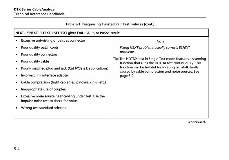
DTX Series CableAnalyzer Technical Reference Handbook
5-4
Table 5-1. Diagnosing Twisted Pair Test Failures (cont.)
NEXT, PSNEXT, ELFEXT, PSELFEXT gives FAIL, FAIL*, or PASS* result
• Excessive untwisting of pairs at connector
• Poor quality patch cords
• Poor quality connectors
• Poor quality cable
• Poorly matched plug and jack (Cat 6/Class E applications)
• Incorrect link interface adapter
• Cable compression (tight cable ties, pinches, kinks, etc.)
• Inappropriate use of couplers
• Excessive noise source near cabling under test. Use the impulse noise test to check for noise.
• Wrong test standard selected
Note
Fixing NEXT problems usually corrects ELFEXT problems.
Tip: The HDTDX test in Single Test mode features a scanning function that runs the HDTDX test continuously. This function can be helpful for locating crosstalk faults caused by cable compression and noise sources. See page 5-9.
-continued-
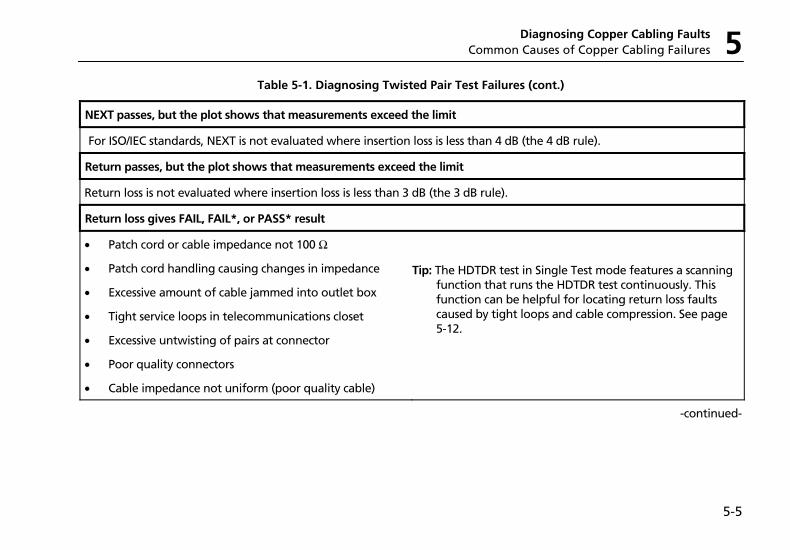
Diagnosing Copper Cabling Faults Common Causes of Copper Cabling Failures 5
5-5
Table 5-1. Diagnosing Twisted Pair Test Failures (cont.)
NEXT passes, but the plot shows that measurements exceed the limit
For ISO/IEC standards, NEXT is not evaluated where insertion loss is less than 4 dB (the 4 dB rule).
Return passes, but the plot shows that measurements exceed the limit
Return loss is not evaluated where insertion loss is less than 3 dB (the 3 dB rule).
Return loss gives FAIL, FAIL*, or PASS* result
• Patch cord or cable impedance not 100 Ω
• Patch cord handling causing changes in impedance
• Excessive amount of cable jammed into outlet box
• Tight service loops in telecommunications closet
• Excessive untwisting of pairs at connector
• Poor quality connectors
• Cable impedance not uniform (poor quality cable)
Tip: The HDTDR test in Single Test mode features a scanning function that runs the HDTDR test continuously. This function can be helpful for locating return loss faults caused by tight loops and cable compression. See page 5-12.
-continued-
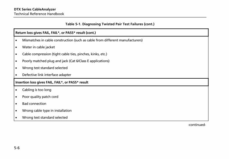
DTX Series CableAnalyzer Technical Reference Handbook
5-6
Table 5-1. Diagnosing Twisted Pair Test Failures (cont.)
Return loss gives FAIL, FAIL*, or PASS* result (cont.)
• Mismatches in cable construction (such as cable from different manufacturers)
• Water in cable jacket
• Cable compression (tight cable ties, pinches, kinks, etc.)
• Poorly matched plug and jack (Cat 6/Class E applications)
• Wrong test standard selected
• Defective link interface adapter
Insertion loss gives FAIL, FAIL*, or PASS* result
• Cabling is too long
• Poor quality patch cord
• Bad connection
• Wrong cable type in installation
• Wrong test standard selected
-continued-
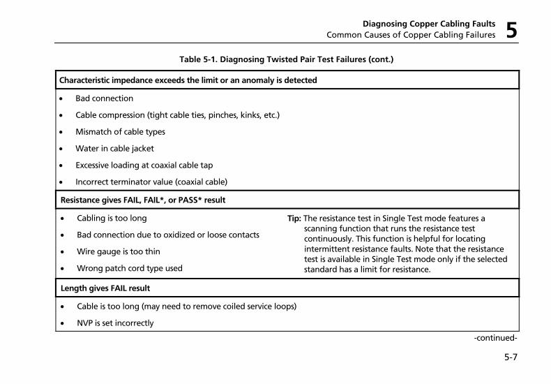
Diagnosing Copper Cabling Faults Common Causes of Copper Cabling Failures 5
5-7
Table 5-1. Diagnosing Twisted Pair Test Failures (cont.)
Characteristic impedance exceeds the limit or an anomaly is detected
• Bad connection
• Cable compression (tight cable ties, pinches, kinks, etc.)
• Mismatch of cable types
• Water in cable jacket
• Excessive loading at coaxial cable tap
• Incorrect terminator value (coaxial cable)
Resistance gives FAIL, FAIL*, or PASS* result
• Cabling is too long
• Bad connection due to oxidized or loose contacts
• Wire gauge is too thin
• Wrong patch cord type used
Tip: The resistance test in Single Test mode features a scanning function that runs the resistance test continuously. This function is helpful for locating intermittent resistance faults. Note that the resistance test is available in Single Test mode only if the selected standard has a limit for resistance.
Length gives FAIL result
• Cable is too long (may need to remove coiled service loops)
• NVP is set incorrectly
-continued-
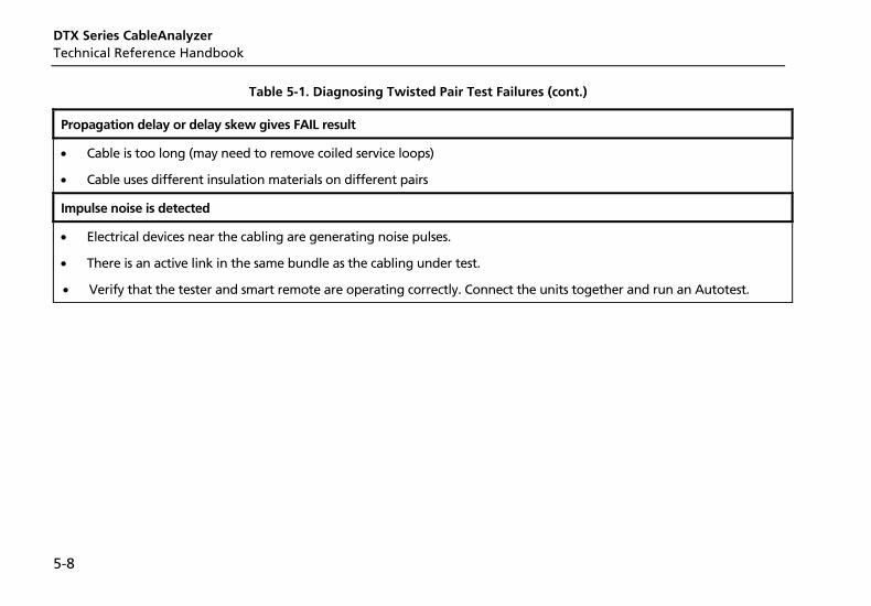
DTX Series CableAnalyzer Technical Reference Handbook
5-8
Table 5-1. Diagnosing Twisted Pair Test Failures (cont.)
Propagation delay or delay skew gives FAIL result
• Cable is too long (may need to remove coiled service loops)
• Cable uses different insulation materials on different pairs
Impulse noise is detected
• Electrical devices near the cabling are generating noise pulses.
• There is an active link in the same bundle as the cabling under test.
• Verify that the tester and smart remote are operating correctly. Connect the units together and run an Autotest.
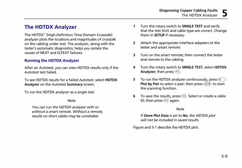
Diagnosing Copper Cabling Faults The HDTDX Analyzer 5
5-9
The HDTDX Analyzer The HDTDX (High-Definition Time Domain Crosstalk) analyzer plots the locations and magnitudes of crosstalk on the cabling under test. The analyzer, along with the tester’s automatic diagnostics, helps you isolate the causes of NEXT and ELFEXT failures.
Running the HDTDX Analyzer
After an Autotest, you can view HDTDX results only if the Autotest test failed.
To see HDTDX results for a failed Autotest, select HDTDX Analyzer on the Autotest Summary screen.
To run the HDTDX analyzer as a single test:
Note
You can run the HDTDX analyzer with or without a smart remote. Without a remote, results on short cables may be unreliable.
1 Turn the rotary switch to SINGLE TEST and verify that the test limit and cable type are correct. Change them in SETUP if necessary.
2 Attach the appropriate interface adapters to the tester and smart remote.
3 Turn on the smart remote; then connect the tester and remote to the cabling.
4 Turn the rotary switch to SINGLE TEST, select HDTDX Analyzer; then press P.
5 To run the HDTDX analyzer continuously, press L Plot by Pair to select a pair; then press H to start the scanning function.
6 To save the results, press N. Select or create a cable ID; then press N again.
Note
If Store Plot Data is set to No, the HDTDX plot will not be included in saved results.
Figure and 5-1 describe the HDTDX plot.
DTX Series CableAnalyzer Technical Reference Handbook
5-10
1
3
4
510
2
6
8 79 amd19f.eps
A The magnitude of crosstalk. Crosstalk levels plotted are adjusted to compensate for insertion loss. This means that the levels represent the magnitudes of the signals as they appear at the crosstalk source.
B The beginning and end of the cabling under test. For a permanent link, the plot shows some of the permanent link adapter cable before and after the cabling under test.
C Magnification level for the plot. Use AD to zoom in or out at the cursor’s location.
D The distance to the end of the cabling.
E The cursor and the distance to the cursor from the tester. Use BC to move the cursor.
F The crosstalk magnitude at the cursor's location.
G Shows the crosstalk plots by pair. Press I to return to the plot of all pairs.
H Toggles the vertical magnification between 1X and 4X.
I Sets or clears the measurement marker. See J.
J The distance between the measurement cursors. To use the measurement cursors:
1 Press J Clear Marker if necessary; then use BC to move the cursor to the beginning of an area of interest. Use AD to zoom in on the area if desired.
2 Press J Set Marker; then use BCto move the second cursor to the end of the area of interest.
Figure 5-1. HDTDX Plot (permanent link adapters used)
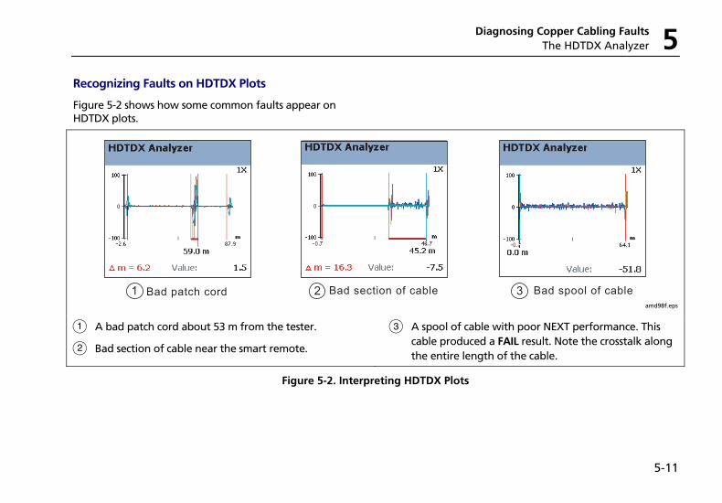
Diagnosing Copper Cabling Faults The HDTDX Analyzer 5
5-11
Recognizing Faults on HDTDX Plots
Figure 5-2 shows how some common faults appear on HDTDX plots.
1 Bad patch cord 2 Bad section of cable 3 Bad spool of cable amd98f.eps
A A bad patch cord about 53 m from the tester.
B Bad section of cable near the smart remote.
C A spool of cable with poor NEXT performance. This cable produced a FAIL result. Note the crosstalk along the entire length of the cable.
Figure 5-2. Interpreting HDTDX Plots
DTX Series CableAnalyzer Technical Reference Handbook
5-12
The HDTDR Analyzer The HDTDR (High-Definition Time Domain Reflectometry) analyzer plots the locations and magnitudes of reflections caused by impedance anomalies. The analyzer, along with the tester’s automatic diagnostics, helps you isolate the causes of return loss failures.
Running the HDTDR Analyzer
After an Autotest, you can view HDTDR results only if the Autotest failed.
To see HDTDR results for failed Autotest, select HDTDR on the Autotest Summary screen.
To run the HDTDR test as a single test:
Note
Though you can run the HDTDR analyzer without a smart remote, the following steps assume you are using a remote.
1 Turn the rotary switch to SINGLE TEST and verify that the test limit and cable type are correct. Change them in SETUP if necessary.
2 Attach the appropriate interface adapters to the tester and smart remote.
3 Turn on the smart remote; then connect the tester and remote to the cabling.
4 Turn the rotary switch to SINGLE TEST, select HDTDR Analyzer; then press P.
5 To run the HDTDR analyzer continuously, press L Plot by Pair to select a pair; then press H to start the scanning function.
6 To save the results, press N. Select or create a cable ID; then press N again.
Note
If Store Plot Data is set to No, the HDTDR plot will not be included in saved results.
Figure 5-3 describes the HDTDR analyzer.
Recognizing Faults on HDTDR Plots
Figure 5-4 shows how some common faults appear on HDTDR plots.
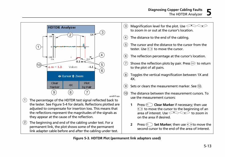
Diagnosing Copper Cabling Faults The HDTDR Analyzer 5
5-13
1
3
4
510
2
6
8 79 amd97f.eps
A The percentage of the HDTDR test signal reflected back to the tester. See Figure 5-4 for details. Reflections plotted are adjusted to compensate for insertion loss. This means that the reflections represent the magnitudes of the signals as they appear at the cause of the reflection.
B The beginning and end of the cabling under test. For a permanent link, the plot shows some of the permanent link adapter cable before and after the cabling under test.
C Magnification level for the plot. Use AD to zoom in or out at the cursor’s location.
D The distance to the end of the cabling.
E The cursor and the distance to the cursor from the tester. Use BC to move the cursor.
F The reflection percentage at the cursor's location.
G Shows the reflection plots by pair. Press I to return to the plot of all pairs.
H Toggles the vertical magnification between 1X and 4X.
I Sets or clears the measurement marker. See J.
J The distance between the measurement cursors. To use the measurement cursors:
1 Press J Clear Marker if necessary; then use BC to move the cursor to the beginning of an area of interest. Use AD to zoom in on the area if desired.
2 Press J Set Marker; then use BCto move the second cursor to the end of the area of interest.
Figure 5-3. HDTDR Plot (permanent link adapters used)
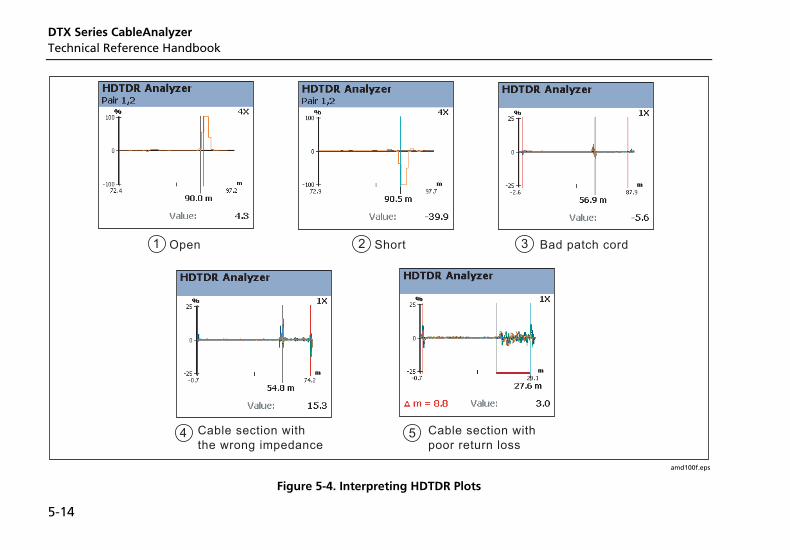
DTX Series CableAnalyzer Technical Reference Handbook
5-14
1 Open 2 Short 3 Bad patch cord
4 Cable section withthe wrong impedance
5 Cable section withpoor return loss
amd100f.eps
Figure 5-4. Interpreting HDTDR Plots
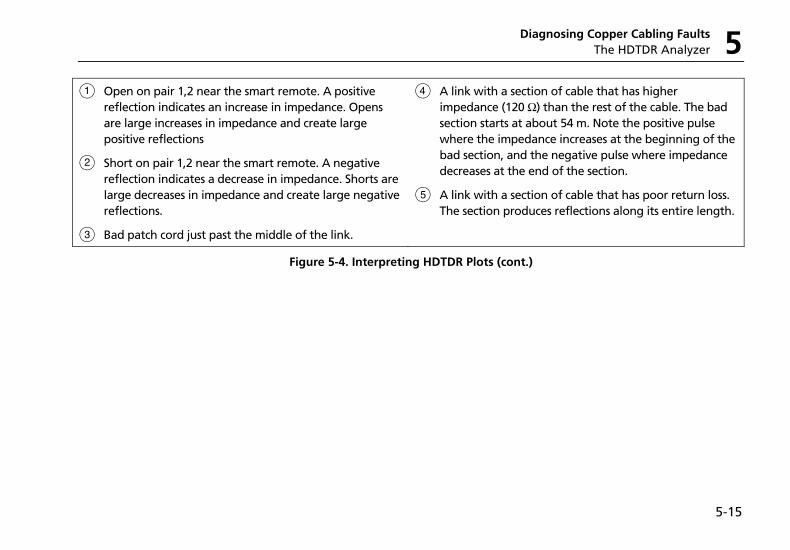
Diagnosing Copper Cabling Faults The HDTDR Analyzer 5
5-15
A Open on pair 1,2 near the smart remote. A positive reflection indicates an increase in impedance. Opens are large increases in impedance and create large positive reflections
B Short on pair 1,2 near the smart remote. A negative reflection indicates a decrease in impedance. Shorts are large decreases in impedance and create large negative reflections.
C Bad patch cord just past the middle of the link.
D A link with a section of cable that has higher impedance (120 Ω ) than the rest of the cable. The bad section starts at about 54 m. Note the positive pulse where the impedance increases at the beginning of the bad section, and the negative pulse where impedance decreases at the end of the section.
E A link with a section of cable that has poor return loss. The section produces reflections along its entire length.
Figure 5-4. Interpreting HDTDR Plots (cont.)

DTX Series CableAnalyzer Technical Reference Handbook
5-16
6-1
Chapter 6 Certifying Fiber Optic Cabling
Overview of Features The optional DTX-MFM2, DTX-GFM2, and DTX-SFM2 fiber modules are used with a DTX Series CableAnalyzer to test and certify fiber optic cabling installations. The fiber modules offer the following functions and features:
• Measures optical power loss and length on dual-fiber cabling. The DTX-MFM2 tests multimode cabling at 850 nm and 1300 nm. The DTX-SFM2 tests singlemode cabling at 1310 nm and 1550 nm. The DTX-GFM2 features a VCSEL for testing multimode cabling at 850 nm and 1310 nm for Gigabit Ethernet applications.
• Each module transmits both wavelengths (850 nm and 1300 nm, 850 nm and 1310 nm, or 1310 nm and 1550 nm).
• Interchangeable connector adapters allow reference and test connections that meet ISO standards for most SFF (small form factor) fiber connectors.
• Provides pass/fail results based on industry-standard limits.
• Visual fault locator helps you locate breaks, bad splices, bends, and check fiber continuity and polarity.
• FindFiber function helps you identify and verify fiber connections.
Figure 6-2 describes the fiber module's features.
DTX Series CableAnalyzer Technical Reference Handbook
6-2
Safety Information
W*Warning: Class 1 and Class 2 Laser Products
To avoid possible eye damage caused by hazardous radiation:
• Never look directly into optical connectors. Some sources produce invisible radiation that can permanently damage your eyes.
• Keep the fiber module’s OUTPUT port covered with a dust cap or keep a reference test cord attached. The OUTPUT port may be active even when a test is not in progress. Covering the port reduces the risk of accidental exposure to hazardous radiation.
• Never start a test or activate the OUTPUT port or VFL port without first connecting a fiber to the port you will use.
• Never look directly into the visual fault locator output. Momentary exposure to the locator’s output will not damage your eyes; however, direct, long-term exposure is potentially hazardous.
• Do not use magnification to view the optical outputs without proper filtering.
• Use of controls, adjustments, or procedures not stated herein might result in hazardous radiation exposure.
Certifying Fiber Optic Cabling Safety Information 6
6-3
WCaution To avoid damaging the tester or cables under test, to avoid data loss, and to ensure maximum accuracy of test results:
• Turn off the tester before attaching or removing modules.
• Leave the module bay covers in place when the fiber modules are not installed.
• When using the fiber modules, use proper cleaning procedures to clean all fiber connectors before every use. Neglecting this step or using improper procedures can cause unreliable test results and may permanently damage the connectors. See page 6-8.
• Cover all connectors with dust caps when not in use.
• Store the connector adapters for the fiber module in the canisters provided.
• Do not touch the photodiode lens (see Figure 6-4).
• Do not overtighten the adapter or use tools to tighten the adapter.
• Use a Fluke Networks FiberInspector Video Microscope to periodically inspect the fiber module’s OUTPUT connector for scratches and other damage.
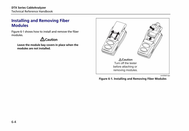
DTX Series CableAnalyzer Technical Reference Handbook
6-4
Installing and Removing Fiber Modules Figure 6-1 shows how to install and remove the fiber modules.
WCaution Leave the module bay covers in place when the modules are not installed.
amd34af.eps
Figure 6-1. Installing and Removing Fiber Modules
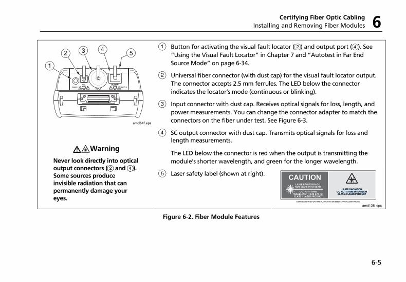
Certifying Fiber Optic Cabling Installing and Removing Fiber Modules 6
6-5
A Button for activating the visual fault locator (B) and output port (D). See “Using the Visual Fault Locator” in Chapter 7 and “Autotest in Far End Source Mode” on page 6-34.
B Universal fiber connector (with dust cap) for the visual fault locator output. The connector accepts 2.5 mm ferrules. The LED below the connector indicates the locator’s mode (continuous or blinking).
C Input connector with dust cap. Receives optical signals for loss, length, and power measurements. You can change the connector adapter to match the connectors on the fiber under test. See Figure 6-3.
D SC output connector with dust cap. Transmits optical signals for loss and length measurements.
The LED below the connector is red when the output is transmitting the module’s shorter wavelength, and green for the longer wavelength.
amd64f.eps
W*Warning
Never look directly into optical output connectors (B and D). Some sources produce invisible radiation that can permanently damage your eyes.
E Laser safety label (shown at right).
CAUTION
amd128i.eps
Figure 6-2. Fiber Module Features
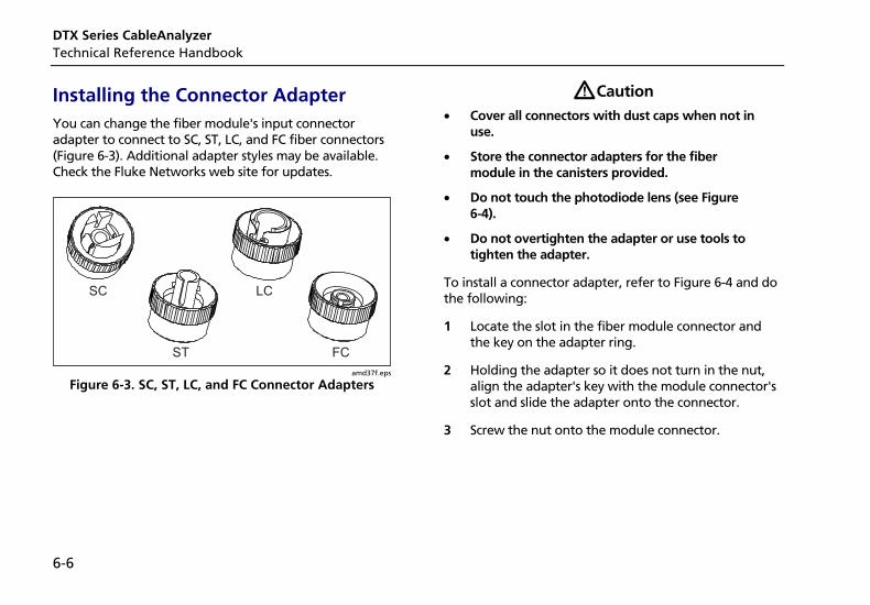
DTX Series CableAnalyzer Technical Reference Handbook
6-6
Installing the Connector Adapter You can change the fiber module's input connector adapter to connect to SC, ST, LC, and FC fiber connectors (Figure 6-3). Additional adapter styles may be available. Check the Fluke Networks web site for updates.
amd37f.eps
Figure 6-3. SC, ST, LC, and FC Connector Adapters
WCaution • Cover all connectors with dust caps when not in
use.
• Store the connector adapters for the fiber module in the canisters provided.
• Do not touch the photodiode lens (see Figure 6-4).
• Do not overtighten the adapter or use tools to tighten the adapter.
To install a connector adapter, refer to Figure 6-4 and do the following:
1 Locate the slot in the fiber module connector and the key on the adapter ring.
2 Holding the adapter so it does not turn in the nut, align the adapter's key with the module connector's slot and slide the adapter onto the connector.
3 Screw the nut onto the module connector.
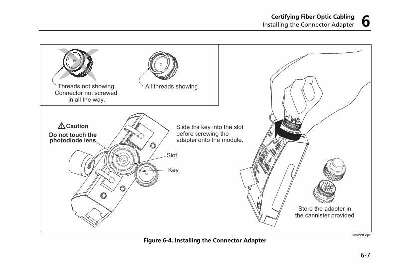
Certifying Fiber Optic Cabling Installing the Connector Adapter 6
6-7
amd99f.eps
Figure 6-4. Installing the Connector Adapter
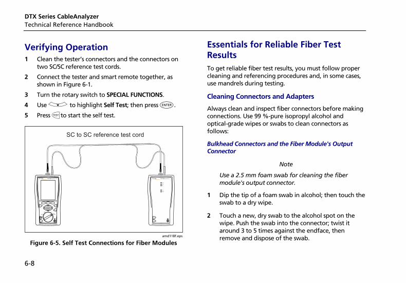
DTX Series CableAnalyzer Technical Reference Handbook
6-8
Verifying Operation 1 Clean the tester’s connectors and the connectors on
two SC/SC reference test cords.
2 Connect the tester and smart remote together, as shown in Figure 6-1.
3 Turn the rotary switch to SPECIAL FUNCTIONS.
4 Use D to highlight Self Test; then press H.
5 Press Pto start the self test.
TALK
MONITOR
ENTER
TEST
SAVE
SPECIALFUNCTIONS
SETUP
AUTOTESTSINGLE
TEST
EXIT
F1 F2 F3
TALK
TEST
PASS
TEST
FAIL
TALK
TONE
SC to SC reference test cord
amd118f.eps
Figure 6-5. Self Test Connections for Fiber Modules
Essentials for Reliable Fiber Test Results To get reliable fiber test results, you must follow proper cleaning and referencing procedures and, in some cases, use mandrels during testing.
Cleaning Connectors and Adapters
Always clean and inspect fiber connectors before making connections. Use 99 %-pure isopropyl alcohol and optical-grade wipes or swabs to clean connectors as follows:
Bulkhead Connectors and the Fiber Module's Output Connector
Note
Use a 2.5 mm foam swab for cleaning the fiber module's output connector.
1 Dip the tip of a foam swab in alcohol; then touch the swab to a dry wipe.
2 Touch a new, dry swab to the alcohol spot on the wipe. Push the swab into the connector; twist it around 3 to 5 times against the endface, then remove and dispose of the swab.
Certifying Fiber Optic Cabling Essentials for Reliable Fiber Test Results 6
6-9
3 Dry the connector with a dry swab by twisting it around in the connector 3 to 5 times.
4 Inspect connectors with a fiber microscope, such as the Fluke Networks FiberInspector Video Microscope before making connections.
Fiber Module's Input Connector
Note
Typically, the input connector requires cleaning only if it has been touched.
1 Remove the connector adapter to expose the photodiode lens (see Figure 6-4).
2 Use the method described in steps 1 and 2 above to dampen a swab with alcohol.
3 Twist the damp swab around against the lens 3 to 5 times; then twist a dry swab around against the lens 3 to 5 times.
Connector Adapters and Fiber Adapters
Periodically clean connector adapters and fiber adapters with a swab and alcohol. Dry with a dry swab before use.
Connector Ends
Wipe the end of the ferrule with a swab or wipe lightly moistened with alcohol. Dry with a dry swab or wipe.
Always cover unused connectors with dust caps or plugs. Clean dust plugs periodically with a swab or wipe and alcohol.
DTX Series CableAnalyzer Technical Reference Handbook
6-10
About Setting the Reference
The reference serves as the baseline power level for loss measurements. Regular referencing helps account for minor variations in source power and connection integrity. Also, since the reference is the baseline for measurements, the losses of the reference test cords and adapters used during referencing are excluded from test results.
Note
Turn on the tester and smart remote and let them sit for 5 minutes before setting the reference. Allow additional time if the modules have been stored above or below ambient temperature.
You should set the reference at these times:
• At the beginning of each day using the remote end setup (Figures 6-10 through 6-18) you will use that day.
• Anytime you reconnect a reference test cord to the module’s output or other source.
• Anytime the tester warns you that the reference is out of date.
• Anytime you see a negative loss measurement. (See Chapter 8.)
You must set the reference at these times:
• Anytime you change the fiber module in the tester or smart remote.
• Anytime you start using a different smart remote.
• Anytime you change the Test Method in Setup.
• Twenty-four hours after the reference was previously set.
WCaution Do not disconnect the reference test cords from the testers' output ports after setting the reference. Doing so may alter the amount of optical power launched into the fiber and invalidate the reference.
Reference values should not change by more than a few tenths of a dB from day to day. Larger changes may indicate a problem with the reference test cords or connections.
See the sections on Smart Remote, Loopback, and Far End Source modes for details on setting the reference for each mode.
Certifying Fiber Optic Cabling Essentials for Reliable Fiber Test Results 6
6-11
After you set the reference, you can enter the lengths of the reference test cords used for reference and test connections. The lengths are included with saved results to meet TSB-140 reporting requirements for fiber test results.
Selecting Reference Test Cords
The DTX Fiber Modules come with high-quality reference test cords.
To ensure that your measurements are accurate and repeatable, use reference test cords provided by Fluke Networks or cords of the same quality. See "Replacing Fiber Reference Test Cords" in Chapter 12.
Testing Your Reference Test Cords
You should test your reference test cords before each job. Use another set of known-good cords to set a reference and run an Autotest on other cords in Smart Remote or Loopback mode. See pages 6-19 and 6-26 for details on running these tests.
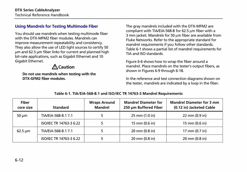
DTX Series CableAnalyzer Technical Reference Handbook
6-12
Using Mandrels for Testing Multimode Fiber
You should use mandrels when testing multimode fiber with the DTX-MFM2 fiber modules. Mandrels can improve measurement repeatability and consistency. They also allow the use of LED light sources to certify 50 µm and 62.5 µm fiber links for current and planned high bit-rate applications, such as Gigabit Ethernet and 10 Gigabit Ethernet.
WCaution Do not use mandrels when testing with the DTX-GFM2 fiber modules.
The gray mandrels included with the DTX-MFM2 are compliant with TIA/EIA-568-B for 62.5 µm fiber with a 3 mm jacket. Mandrels for 50 µm fiber are available from Fluke Networks. Refer to the appropriate standard for mandrel requirements if you follow other standards. Table 6-1 shows a partial list of mandrel requirements for TIA and ISO standards.
Figure 6-6 shows how to wrap the fiber around a mandrel. Place mandrels on the tester’s output fibers, as shown in Figures 6-9 through 6-18.
In the reference and test connection diagrams shown on the tester, mandrels are indicated by a loop in the fiber.
Table 6-1. TIA/EIA-568-B.1 and ISO/IEC TR 14763-3 Mandrel Requirements
Fiber core size
Standard
Wraps Around Mandrel
Mandrel Diameter for 250 µm Buffered Fiber
Mandrel Diameter for 3 mm (0.12 in) Jacketed Cable
50 µm TIA/EIA-568-B.1 7.1 5 25 mm (1.0 in) 22 mm (0.9 in)
ISO/IEC TR 14763-3 6.22 5 15 mm (0.6 in) 15 mm (0.6 in)
62.5 µm TIA/EIA-568-B.1 7.1 5 20 mm (0.8 in) 17 mm (0.7 in)
ISO/IEC TR 14763-3 6.22 5 20 mm (0.8 in) 20 mm (0.8 in)
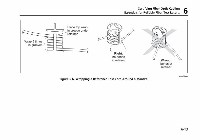
Certifying Fiber Optic Cabling Essentials for Reliable Fiber Test Results 6
6-13
Wrap 5 timesin grooves
Place top wrap in groove underretainer
Right:no bendsat retainer Wrong:
bends atretainer
amd67f.eps
Figure 6-6. Wrapping a Reference Test Cord Around a Mandrel
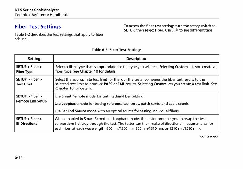
DTX Series CableAnalyzer Technical Reference Handbook
6-14
Fiber Test Settings Table 6-2 describes the test settings that apply to fiber cabling.
To access the fiber test settings turn the rotary switch to SETUP; then select Fiber. Use BC to see different tabs.
Table 6-2. Fiber Test Settings
Setting Description
SETUP > Fiber > Fiber Type
Select a fiber type that is appropriate for the type you will test. Selecting Custom lets you create a fiber type. See Chapter 10 for details.
SETUP > Fiber > Test Limit
Select the appropriate test limit for the job. The tester compares the fiber test results to the selected test limit to produce PASS or FAIL results. Selecting Custom lets you create a test limit. See Chapter 10 for details.
SETUP > Fiber > Remote End Setup
Use Smart Remote mode for testing dual-fiber cabling.
Use Loopback mode for testing reference test cords, patch cords, and cable spools.
Use Far End Source mode with an optical source for testing individual fibers.
SETUP > Fiber > Bi-Directional
When enabled in Smart Remote or Loopback mode, the tester prompts you to swap the test connections halfway through the test. The tester can then make bi-directional measurements for each fiber at each wavelength (850 nm/1300 nm, 850 nm/1310 nm, or 1310 nm/1550 nm).
-continued-
Certifying Fiber Optic Cabling Fiber Test Settings 6
6-15
Table 6-2. Fiber Test Settings (cont.)
Setting Description
SETUP > Fiber > Number of Adapters
SETUP > Fiber > Number of Splices
If the selected limit uses a calculated loss limit, enter the number of adapters and splices that will be added to the fiber path after the reference is set. Figure 6-7 shows an example of how to determine the Number of Adapters setting.
Only limits that use maximum values for loss per km, loss per connector, and loss per splice use a calculated limit for overall loss. For example, limits for fiber backbones use a calculated loss limit.
SETUP > Fiber > Connector Type
Select the type of connector used in the cabling. This setting affects only the diagrams shown for reference connections. If the cabling's connector type is not listed, use General.
SETUP > Fiber > Test Method > Method A, B, C
Loss results include connections added after referencing. The reference and test connections determine which connections are included in results. The Test Method refers to the number of end connections included:
Method A: Loss results include one connection at one end of the link.
Method B: Loss results include connections at both ends of the link. Select this method for connections shown in this manual. See "About Method B Connections" on page 6-18.
Method C: Loss results exclude connections at the ends of the link. Only the fiber loss is measured.
Different standards have different names for the three test methods. See Appendix A for details.
The Test Method setting does affect the reference and test connection diagrams shown on the tester's display. The diagrams show connections for the method selected.
-continued-
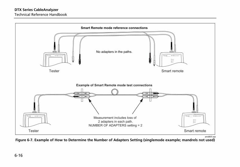
DTX Series CableAnalyzer Technical Reference Handbook
6-16
amd65f.eps
Figure 6-7. Example of How to Determine the Number of Adapters Setting (singlemode example; mandrels not used)
Certifying Fiber Optic Cabling Fiber Test Settings 6
6-17
Table 6-2. Fiber Test Settings (cont.)
Setting Description
SETUP > Fiber > Index of Ref. Source (n) > User Defined or Default
The tester uses the index of refraction (n) defined in the currently selected fiber type (Default) or a value you define (User Defined). The default value defined by the selected fiber type represents the typical value for that fiber type. You may enter a different value if necessary. To determine the actual value, change the index of refraction until the measured length matches the known length of a fiber.
Increasing the index of refraction decreases the reported length.
SPECIAL FUNCTIONS > Set Reference
Patch Lengths (softkey on the View Connections screen)
Setting a reference sets the baseline power level for loss measurements. See “About Setting the Reference” on page 6-10.
After you set the reference, you can enter the lengths of the reference test cords used. The lengths you enter do not affect measurements. They are included with saved results to meet TSB-140 reporting requirements.
SETUP > Instrument Settings
Settings for saving tests
Cable ID Source, Current Folder, Result Storage Location (DTX-1800, DTX-1200), Operator, Site, and Company. See “Preparing to Save Tests” in Chapter 2.
DTX Series CableAnalyzer Technical Reference Handbook
6-18
About Method B Connections The reference and test connections shown in this manual produce Method B results. Method B results include the loss of the fiber plus the loss of the connections at both ends of the link. To ensure accurate results, the connection to the fiber module's output port must not be disconnected after the reference is set. Using connector adapters that match the connectors in the fiber under test lets you connect to the fiber without disturbing the output port connection.
WCaution If you disconnect the reference test cords from the tester’s or smart remote’s output port after setting the reference, you must set the reference again to ensure valid measurements.
If you do not have the correct connector adapters, see Appendix B for modified Method B and alternative connections that produce Method B results.
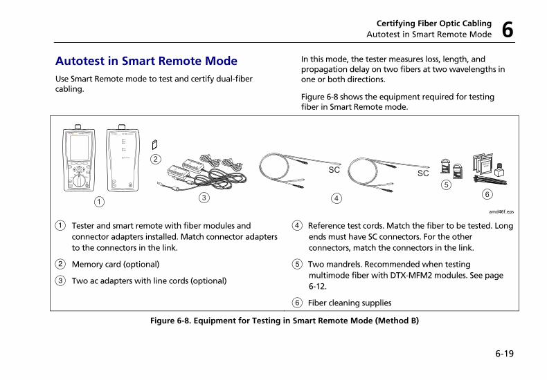
Certifying Fiber Optic Cabling Autotest in Smart Remote Mode 6
6-19
Autotest in Smart Remote Mode Use Smart Remote mode to test and certify dual-fiber cabling.
In this mode, the tester measures loss, length, and propagation delay on two fibers at two wavelengths in one or both directions.
Figure 6-8 shows the equipment required for testing fiber in Smart Remote mode.
amd46f.eps
A Tester and smart remote with fiber modules and connector adapters installed. Match connector adapters to the connectors in the link.
B Memory card (optional)
C Two ac adapters with line cords (optional)
D Reference test cords. Match the fiber to be tested. Long ends must have SC connectors. For the other connectors, match the connectors in the link.
E Two mandrels. Recommended when testing multimode fiber with DTX-MFM2 modules. See page 6-12.
F Fiber cleaning supplies
Figure 6-8. Equipment for Testing in Smart Remote Mode (Method B)
DTX Series CableAnalyzer Technical Reference Handbook
6-20
Setting the Reference for Smart Remote Mode
1 Turn on both testers and let them sit for 5 minutes. Allow additional time if the modules have been stored above or below ambient temperature.
2 Turn the rotary switch to SETUP, then select Fiber.
3 Select Remote End Setup, then select Smart Remote.
4 Turn the rotary switch to SPECIAL FUNCTIONS, then select Set Reference. If both a fiber module and a twisted pair or coaxial adapter are attached, select Fiber Module next.
5 Clean the connectors on the tester, smart remote, and reference test cords. Connect the tester and smart remote as shown on the tester.
Notes
The Set Reference screen shows reference connections for the selected test method. Figure 6-9 shows connections for Method B.
The reference test cords in the tester’s diagrams are numbered. If you want to meet TSB-140 reporting requirements, you can enter lengths for each reference test cord number after setting the reference.
6 Press P.
The View Reference screen shows the reference values and the date and time the reference was set.
7 Press K OK.
The View Connections screen shows the test connections for the selected test method.
8 To enter reference test cord lengths to meet TSB-140 reporting requirements, press J Patch Lengths.
On the Patch Lengths screen, enter the lengths of the reference test cords.
Press N when you are done.
WCaution Do not disconnect the reference test cords from the tester’s or smart remote’s output port after setting the reference. If you do, you must set the reference again to ensure valid measurements.
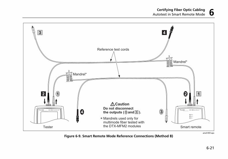
Certifying Fiber Optic Cabling Autotest in Smart Remote Mode 6
6-21
amd145f.eps
Figure 6-9. Smart Remote Mode Reference Connections (Method B)
DTX Series CableAnalyzer Technical Reference Handbook
6-22
Running the Autotest in Smart Remote Mode
WCaution If the reference test cords have been disconnected from the tester’s or smart remote’s output since the reference was set, you must set the reference again to ensure valid measurements.
1 Turn on the tester and smart remote and let them sit for 5 minutes. Allow additional time if the modules have been stored above or below ambient temperature.
2 Verify that the settings described in Table 6-2 are appropriate.
3 Clean the connectors on the cabling to be tested.
4 Connect the tester to the cabling. Figure 6-10 shows test connections for Method B.
5 Turn the rotary switch to AUTOTEST. Verify that the media type is set to Fiber. Press J Change Media to change it if necessary.
6 Press P.
7 If Open or Unknown appears as the status, try the following:
• Verify that all connections are good.
• Verify that the remote tester is on.
• Try different connections to the cabling until the test continues. See “Using FindFiber in Smart Remote Mode” on page 6-44 for details on FindFiber messages.
• Use a the visual fault locator to verify fiber continuity.
8 To save the results, press N, select or create a fiber ID for one fiber; then press N.
Select or create a fiber ID for the other fiber; then press N again.
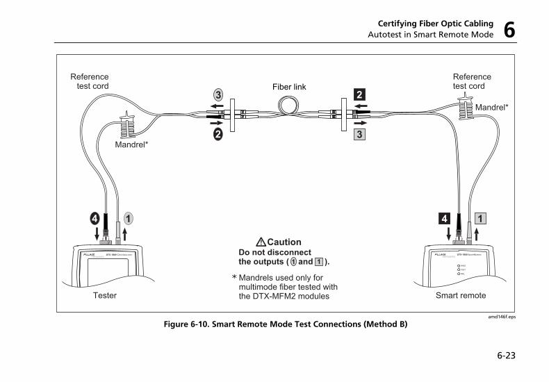
Certifying Fiber Optic Cabling Autotest in Smart Remote Mode 6
6-23
amd146f.eps
Figure 6-10. Smart Remote Mode Test Connections (Method B)
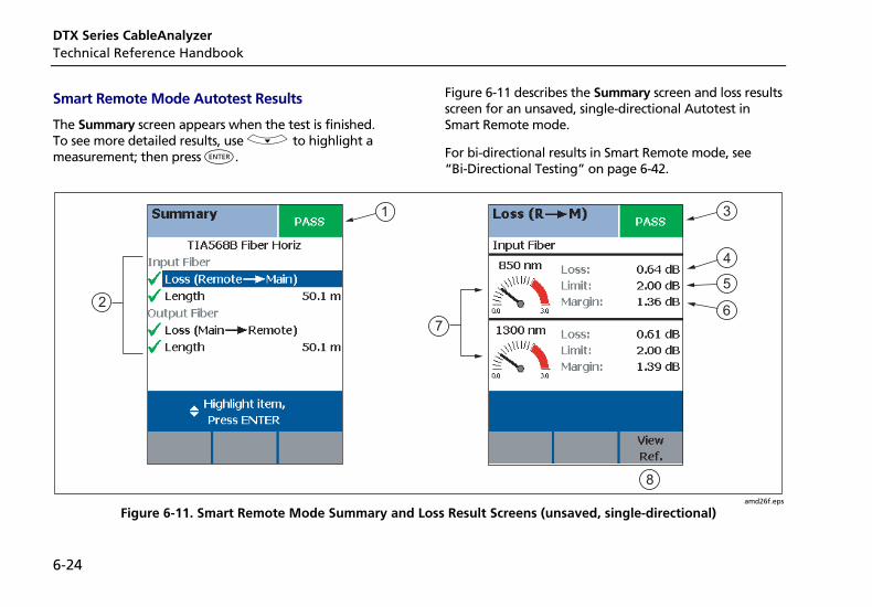
DTX Series CableAnalyzer Technical Reference Handbook
6-24
Smart Remote Mode Autotest Results
The Summary screen appears when the test is finished. To see more detailed results, use D to highlight a measurement; then press H.
Figure 6-11 describes the Summary screen and loss results screen for an unsaved, single-directional Autotest in Smart Remote mode.
For bi-directional results in Smart Remote mode, see “Bi-Directional Testing” on page 6-42.
1 3
7
4
5
6
8
2
amd26f.eps
Figure 6-11. Smart Remote Mode Summary and Loss Result Screens (unsaved, single-directional)
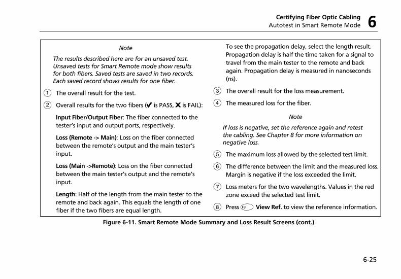
Certifying Fiber Optic Cabling Autotest in Smart Remote Mode 6
6-25
Note
The results described here are for an unsaved test. Unsaved tests for Smart Remote mode show results for both fibers. Saved tests are saved in two records. Each saved record shows results for one fiber.
A The overall result for the test.
B Overall results for the two fibers (E is PASS, F is FAIL):
Input Fiber/Output Fiber: The fiber connected to the tester’s input and output ports, respectively.
Loss (Remote -> Main): Loss on the fiber connected between the remote’s output and the main tester’s input.
Loss (Main ->Remote): Loss on the fiber connected between the main tester’s output and the remote’s input.
Length: Half of the length from the main tester to the remote and back again. This equals the length of one fiber if the two fibers are equal length.
To see the propagation delay, select the length result. Propagation delay is half the time taken for a signal to travel from the main tester to the remote and back again. Propagation delay is measured in nanoseconds (ns).
C The overall result for the loss measurement.
D The measured loss for the fiber.
Note
If loss is negative, set the reference again and retest the cabling. See Chapter 8 for more information on negative loss.
E The maximum loss allowed by the selected test limit.
F The difference between the limit and the measured loss. Margin is negative if the loss exceeded the limit.
G Loss meters for the two wavelengths. Values in the red zone exceed the selected test limit.
H Press L View Ref. to view the reference information.
Figure 6-11. Smart Remote Mode Summary and Loss Result Screens (cont.)
DTX Series CableAnalyzer Technical Reference Handbook
6-26
Autotest in Loopback Mode Use Loopback mode to test spools of cable, segments of uninstalled cable, and patch cords.
In this mode, the tester measures loss, length, and propagation delay at two wavelengths in one or both directions.
Figure 6-12 shows the equipment required for testing fiber in Loopback mode.
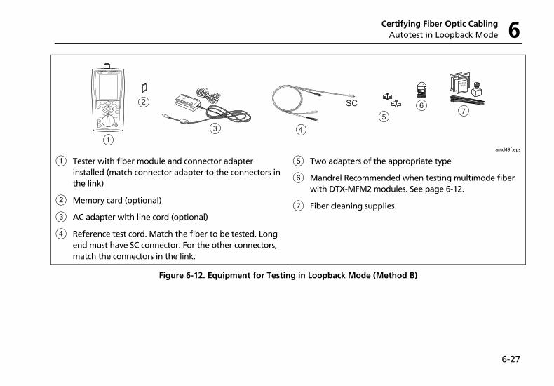
Certifying Fiber Optic Cabling Autotest in Loopback Mode 6
6-27
amd49f.eps
A Tester with fiber module and connector adapter installed (match connector adapter to the connectors in the link)
B Memory card (optional)
C AC adapter with line cord (optional)
D Reference test cord. Match the fiber to be tested. Long end must have SC connector. For the other connectors, match the connectors in the link.
E Two adapters of the appropriate type
F Mandrel Recommended when testing multimode fiber with DTX-MFM2 modules. See page 6-12.
G Fiber cleaning supplies
Figure 6-12. Equipment for Testing in Loopback Mode (Method B)
DTX Series CableAnalyzer Technical Reference Handbook
6-28
Setting the Reference in Loopback Mode
1 Turn on the tester and let it sit for 5 minutes. Allow additional time if the modules have been stored above or below ambient temperature.
2 Turn the rotary switch to SETUP; then select Fiber.
3 Select Remote End Setup; then select Loopback.
4 Turn the rotary switch to SPECIAL FUNCTIONS; then select Set Reference. If both a fiber module and a twisted pair or coaxial adapter are attached, select Fiber Module next.
5 Clean the connectors on the tester and reference test cords. Connect the reference test cords as shown on the tester.
Notes
The Set Reference screen shows reference connections for the selected test method. Figure 6-13 shows connections for Method B.
The reference test cords in the tester’s diagrams are numbered. If you want to meet TSB-140 reporting requirements, you can enter lengths for each reference test cord number after setting the reference.
6 Press P.
The View Reference screen shows the reference values and the date and time the reference was set.
7 Press K OK.
The View Connections screen shows the test connections for the selected test method.
8 To enter reference test cord lengths to meet TSB-140 reporting requirements, press J Patch Lengths.
On the Patch Lengths screen, enter the lengths of the reference test cords.
Press N when you are done.
WCaution Do not disconnect the reference test cords from the tester’s output after setting the reference. If you do, you must set the reference again to ensure valid measurements.
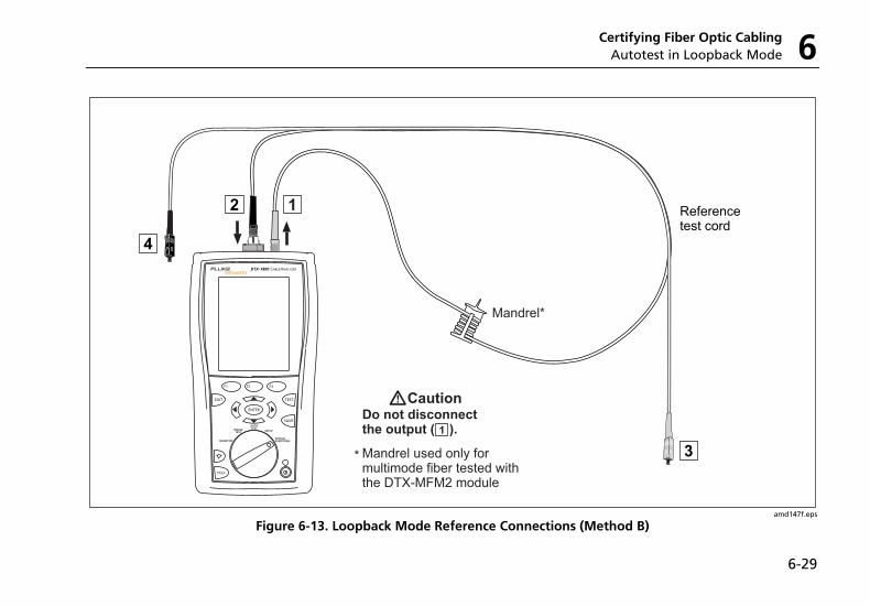
Certifying Fiber Optic Cabling Autotest in Loopback Mode 6
6-29
amd147f.eps
Figure 6-13. Loopback Mode Reference Connections (Method B)
DTX Series CableAnalyzer Technical Reference Handbook
6-30
Running the Autotest in Loopback Mode
WCaution If the reference test cords have been disconnected from the tester’ output since the reference was set, you must set the reference again to ensure valid measurements.
1 Turn on the tester and let it sit for 5 minutes. Allow additional time if the module has been stored above or below ambient temperature.
2 Verify that the settings described in Table 6-2 are appropriate.
3 Clean the connectors on the cabling to be tested.
4 Connect the tester to the cabling. Figure 6-14 shows connections for Method B.
5 Turn the rotary switch to AUTOTEST. Verify that the media type is set to Fiber. Press J Change Media to change it if necessary.
6 Press P.
7 To save the results, press N; select or create a fiber ID; then press N again.
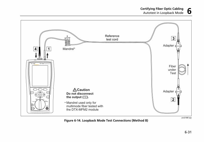
Certifying Fiber Optic Cabling Autotest in Loopback Mode 6
6-31
amd148f.eps
Figure 6-14. Loopback Mode Test Connections (Method B)
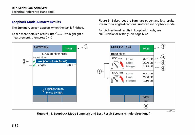
DTX Series CableAnalyzer Technical Reference Handbook
6-32
Loopback Mode Autotest Results
The Summary screen appears when the test is finished.
To see more detailed results, use D to highlight a measurement; then press H.
Figure 6-15 describes the Summary screen and loss results screen for a single-directional Autotest in Loopback mode.
For bi-directional results in Loopback mode, see “Bi-Directional Testing” on page 6-42.
1 3
7
4
5
6
8
2
amd27f.eps
Figure 6-15. Loopback Mode Summary and Loss Result Screens (single-directional)
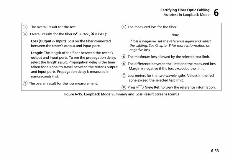
Certifying Fiber Optic Cabling Autotest in Loopback Mode 6
6-33
A The overall result for the test.
B Overall results for the fiber (E is PASS, F is FAIL):
Loss (Output -> Input): Loss on the fiber connected between the tester’s output and input ports.
Length: The length of the fiber between the tester’s output and input ports. To see the propagation delay, select the length result. Propagation delay is the time taken for a signal to travel between the tester’s output and input ports. Propagation delay is measured in nanoseconds (ns).
C The overall result for the loss measurement.
D The measured loss for the fiber.
Note
If loss is negative, set the reference again and retest the cabling. See Chapter 8 for more information on negative loss.
E The maximum loss allowed by the selected test limit.
F The difference between the limit and the measured loss. Margin is negative if the loss exceeded the limit.
G Loss meters for the two wavelengths. Values in the red zone exceed the selected test limit.
H Press L View Ref. to view the reference information.
Figure 6-15. Loopback Mode Summary and Loss Result Screens (cont.)
DTX Series CableAnalyzer Technical Reference Handbook
6-34
Autotest in Far End Source Mode Use Far End Source mode to measure power or power loss at one wavelength on individual fibers.
Far End Source mode requires a stand-alone optical source, such as a DTX smart remote with a fiber module.
You can also use other sources, such as a Fluke Networks SimpliFiber source or LS-1310/1550 laser source.
Figure 6-16 shows the equipment required for measuring loss in Far End Source mode.
Note
The Autotest in Far End Source mode does not show a PASS/FAIL result, limit, or margin if the selected test limit calculates loss based on fiber length. An example of such a limit is the TIA-568B Fiber Backbone limit. The tester does not measure length in Far End Source mode.
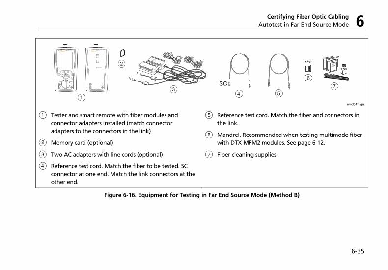
Certifying Fiber Optic Cabling Autotest in Far End Source Mode 6
6-35
amd51f.eps
A Tester and smart remote with fiber modules and connector adapters installed (match connector adapters to the connectors in the link)
B Memory card (optional)
C Two AC adapters with line cords (optional)
D Reference test cord. Match the fiber to be tested. SC connector at one end. Match the link connectors at the other end.
E Reference test cord. Match the fiber and connectors in the link.
F Mandrel. Recommended when testing multimode fiber with DTX-MFM2 modules. See page 6-12.
G Fiber cleaning supplies
Figure 6-16. Equipment for Testing in Far End Source Mode (Method B)
DTX Series CableAnalyzer Technical Reference Handbook
6-36
Setting the Reference in Far End Source Mode
1 Turn on the tester and smart remote and let them sit for 5 minutes. Allow additional time if the fiber modules have been stored above or below ambient temperature. For other sources, warm up according to the manufacturer’s recommendations.
2 Turn the rotary switch to SETUP; then select Fiber.
3 Select Remote End Setup; then select Far End Source.
4 Turn the rotary switch to SPECIAL FUNCTIONS; then select Set Reference. If both a fiber module and a twisted pair or coaxial adapter are attached, select Fiber Module next.
5 Clean the connectors on the tester, source, and reference test cords. Connect the tester and source as shown on the tester.
Notes
The Set Reference screen shows reference connections for the selected test method. Figure 6-17 shows connections for Method B.
The reference test cords in the tester’s diagrams are numbered. If you want to meet TSB-140 reporting requirements, you can enter lengths for each reference test cord number after setting the reference.
7 Hold down the button on the smart remote’s fiber module for 3 seconds to turn on the output port at 850 nm (DTX-MFM2/GFM2) or 1310 nm (DTX-SFM2). Press again to switch to 1300 nm (DTX-MFM2), 1310 nm (DTX-GFM2), or 1550 nm (DTX-SFM2).
The LED is red for the shorter wavelength and green for the longer wavelength.
For other sources, verify the output is set to the correct wavelength and is in continuous-wave mode.
9 Press P, highlight the appropriate wavelength; then press P again.
The View Reference screen shows the reference values and the date and time the reference was set.
10 Press K OK.
The View Connections screen shows the test connections for the selected test method.
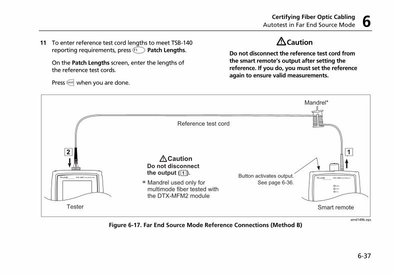
Certifying Fiber Optic Cabling Autotest in Far End Source Mode 6
6-37
11 To enter reference test cord lengths to meet TSB-140 reporting requirements, press J Patch Lengths.
On the Patch Lengths screen, enter the lengths of the reference test cords.
Press N when you are done.
WCaution Do not disconnect the reference test cord from the smart remote’s output after setting the reference. If you do, you must set the reference again to ensure valid measurements.
amd149b.eps
Figure 6-17. Far End Source Mode Reference Connections (Method B)
DTX Series CableAnalyzer Technical Reference Handbook
6-38
Running the Autotest in Far End Source Mode
WCaution If the reference test cord has been disconnected from the smart remote’s output since the reference was set, you must set the reference again to ensure valid measurements.
1 Turn on the tester and smart remote and let them sit for 5 minutes. Allow additional time if the fiber modules have been stored above or below ambient temperature. For other sources, warm up according to the manufacturer’s recommendations.
2 Verify that the settings described in Table 6-2 are appropriate. Clean the connectors on the cabling to be tested.
3 Connect the tester to the cabling as shown in Figure 6-18.
4 Verify the source is set to the correct wavelength.
To set the wavelength on a DTX module used as a source, hold down the button on the smart remote’s
fiber module for 3 seconds. This turns on the output port at 850 nm (DTX-MFM2/GFM2) or 1310 nm (DTX-SFM2). Press again to switch to 1300 nm (DTX-MFM2), 1310 nm (DTX-GFM2), or 1550 nm (DTX-SFM2).
The LED is red for the shorter wavelength and green for the longer wavelength.
For other sources, verify the output is set to the correct wavelength and is in continuous-wave mode.
5 Turn the rotary switch to Autotest. Verify that the media type is set to Fiber. Press J Change Media to change it if necessary.
6 Press P, highlight the appropriate wavelength; then press P again.
7 To save the results, press N, select or create a fiber ID; then press Nagain.
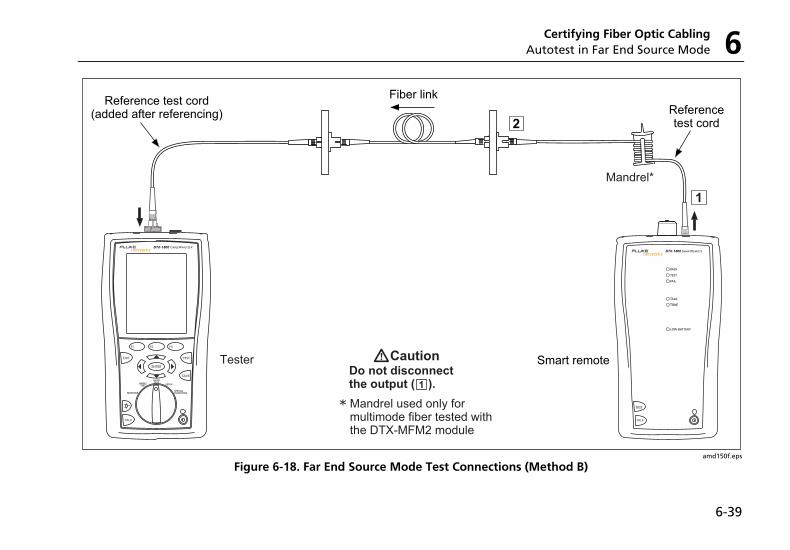
Certifying Fiber Optic Cabling Autotest in Far End Source Mode 6
6-39
amd150f.eps
Figure 6-18. Far End Source Mode Test Connections (Method B)
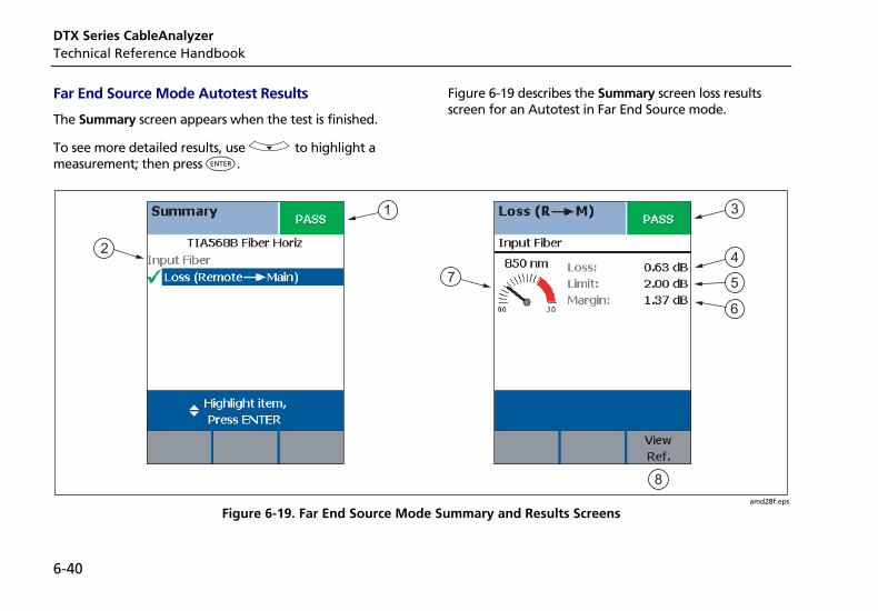
DTX Series CableAnalyzer Technical Reference Handbook
6-40
Far End Source Mode Autotest Results
The Summary screen appears when the test is finished.
To see more detailed results, use D to highlight a measurement; then press H.
Figure 6-19 describes the Summary screen loss results screen for an Autotest in Far End Source mode.
1
2
3
74
5
6
8
amd28f.eps
Figure 6-19. Far End Source Mode Summary and Results Screens
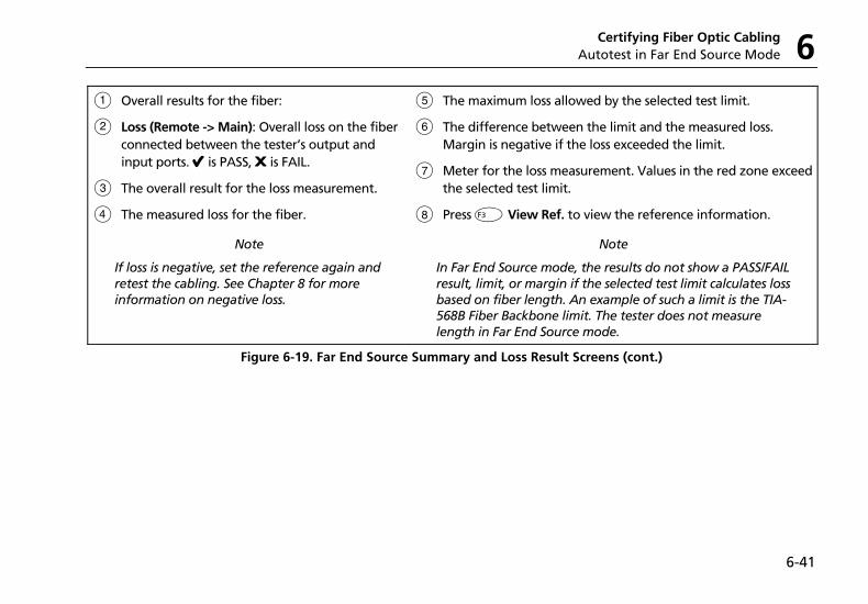
Certifying Fiber Optic Cabling Autotest in Far End Source Mode 6
6-41
A Overall results for the fiber:
B Loss (Remote -> Main): Overall loss on the fiber connected between the tester’s output and input ports. E is PASS, F is FAIL.
C The overall result for the loss measurement.
D The measured loss for the fiber.
Note
If loss is negative, set the reference again and retest the cabling. See Chapter 8 for more information on negative loss.
E The maximum loss allowed by the selected test limit.
F The difference between the limit and the measured loss. Margin is negative if the loss exceeded the limit.
G Meter for the loss measurement. Values in the red zone exceed the selected test limit.
H Press L View Ref. to view the reference information.
Note
In Far End Source mode, the results do not show a PASS/FAIL result, limit, or margin if the selected test limit calculates loss based on fiber length. An example of such a limit is the TIA-568B Fiber Backbone limit. The tester does not measure length in Far End Source mode.
Figure 6-19. Far End Source Summary and Loss Result Screens (cont.)
DTX Series CableAnalyzer Technical Reference Handbook
6-42
Bi-Directional Testing The Bi-Directional setting lets you test cabling in both directions and save the bi-directional test results in Smart Remote and Loopback modes.
To run a bi-directional test:
1 Turn the rotary switch to SETUP; then select Fiber.
2 Select Bi-Directional; then select Yes.
3 Run an Autotest test on the cabling, as described in the previous sections for Smart Remote mode and Loopback mode.
4 Halfway through the test, the tester prompts you to swap the fibers at each end of the cabling.
WCaution Swap the connections at the patch panel, not at the tester's ports. Disconnecting the reference test cord from the tester’s output port invalidates the reference.
5 When the test is complete, press N to save the results. Select or create a fiber ID for the fiber; then press N again.
In Smart Remote mode, you save two results, one for each fiber. See the next section.
Bi-Directional Results for Smart Remote Mode
Unsaved tests show the results for both fibers, as shown at the left of Figure 6-20. Input Fiber and Output Fiber refer to the fibers connected to the main tester’s input and output ports at the end of the test.
On the results screen for loss and length measurements for each fiber, press J Other Dir. to see results for the other direction.
Saved tests for Smart Remote mode are stored in two records, one for each fiber, as shown at the right of Figure 6-20. Each record contains bi-directional results for one fiber.
Bi-Directional Results for Loopback Mode
In the results for Loopback mode, Output to Input refers to the direction from the tester’s output port to its input port. Input to Output refers to the direction from the tester’s input port to its output port. Both results are stored in one record.
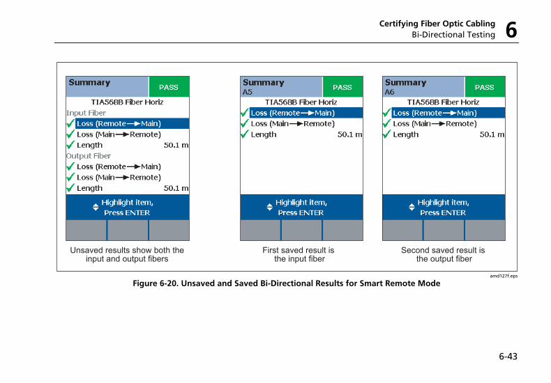
Certifying Fiber Optic Cabling Bi-Directional Testing 6
6-43
First saved result is the input fiber
Second saved result is the output fiber
Unsaved results show both theinput and output fibers
amd127f.eps
Figure 6-20. Unsaved and Saved Bi-Directional Results for Smart Remote Mode
DTX Series CableAnalyzer Technical Reference Handbook
6-44
Finding Connections with FindFiber The FindFiber function helps you trace connections at patch panels and quickly check fiber continuity.
Note
The FindFiber function is not available in Far End Source mode.
Using FindFiber in Smart Remote Mode
Use the FindFiber function in Smart Remote mode to help you determine which fibers go to which connectors at a patch panel.
Figure 6-21 shows the equipment needed for using FindFiber in Smart Remote mode.
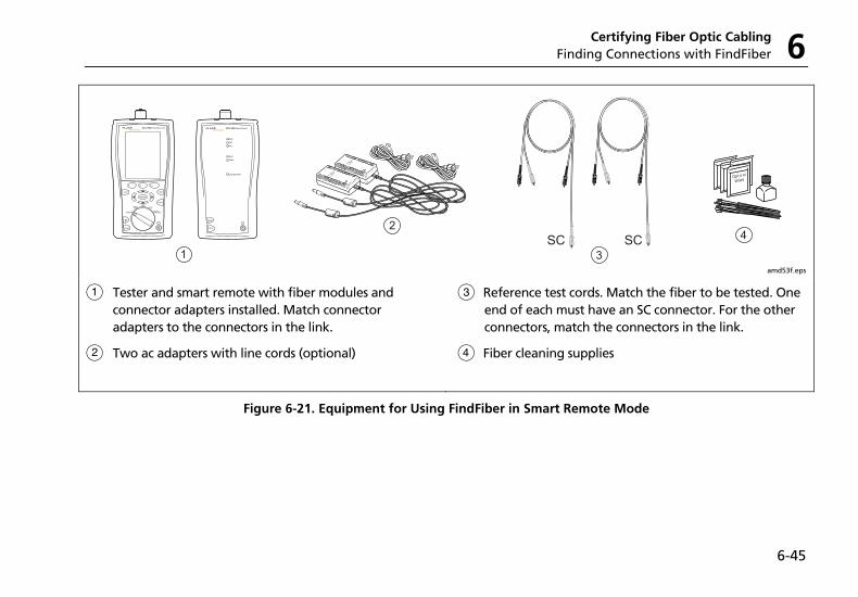
Certifying Fiber Optic Cabling Finding Connections with FindFiber 6
6-45
Wipe
1
2
3
4SCSC
amd53f.eps
A Tester and smart remote with fiber modules and connector adapters installed. Match connector adapters to the connectors in the link.
B Two ac adapters with line cords (optional)
C Reference test cords. Match the fiber to be tested. One end of each must have an SC connector. For the other connectors, match the connectors in the link.
D Fiber cleaning supplies
Figure 6-21. Equipment for Using FindFiber in Smart Remote Mode
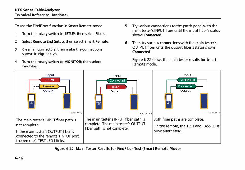
DTX Series CableAnalyzer Technical Reference Handbook
6-46
To use the FindFiber function in Smart Remote mode:
1 Turn the rotary switch to SETUP; then select Fiber.
2 Select Remote End Setup; then select Smart Remote.
3 Clean all connectors; then make the connections shown in Figure 6-23.
4 Turn the rotary switch to MONITOR; then select FindFiber.
5 Try various connections to the patch panel with the main tester’s INPUT fiber until the input fiber’s status shows Connected.
6 Then try various connections with the main tester’s OUTPUT fiber until the output fiber’s status shows Connected.
Figure 6-22 shows the main tester results for Smart Remote mode.
amd103f.eps
amd104f.eps
amd105f.eps
The main tester’s INPUT fiber path is not complete.
If the main tester's OUTPUT fiber is connected to the remote's INPUT port, the remote's TEST LED blinks.
The main tester’s INPUT fiber path is complete. The main tester’s OUTPUT fiber path is not complete.
Both fiber paths are complete.
On the remote, the TEST and PASS LEDs blink alternately.
Figure 6-22. Main Tester Results for FindFiber Test (Smart Remote Mode)
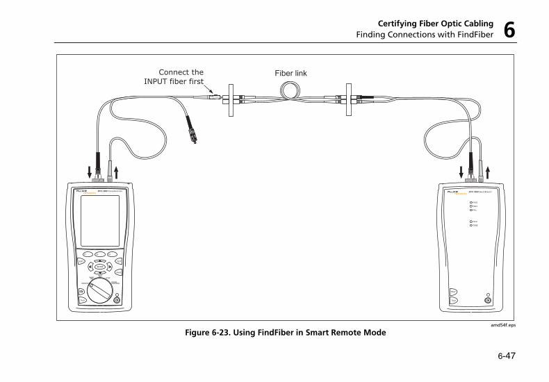
Certifying Fiber Optic Cabling Finding Connections with FindFiber 6
6-47
Connect the
INPUT fiber first
TALK
TEST
PASS
TEST
FAIL
TALK
TONE
TALK
MONITOR
ENTER
TEST
SAVE
SPECIAL FUNCTIONS
SETUP
AUTO TESTSINGLE
TEST
EXIT
F1 F2 F3
amd54f.eps
Figure 6-23. Using FindFiber in Smart Remote Mode
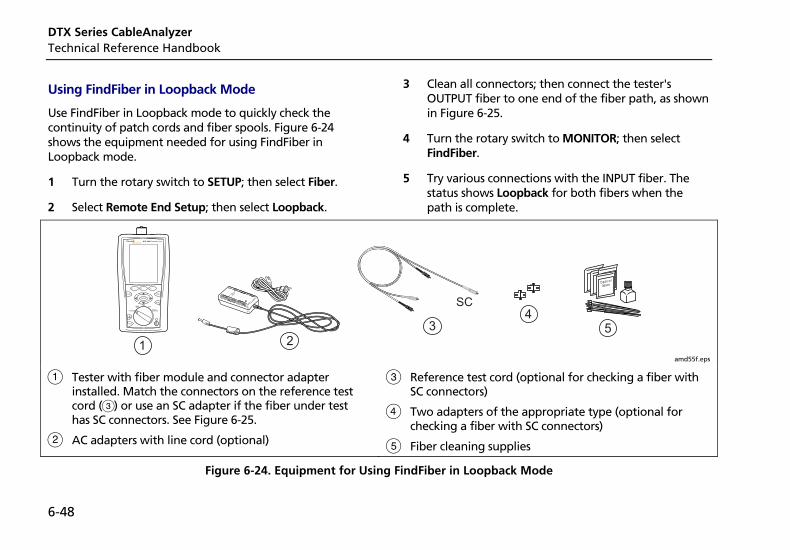
DTX Series CableAnalyzer Technical Reference Handbook
6-48
Using FindFiber in Loopback Mode
Use FindFiber in Loopback mode to quickly check the continuity of patch cords and fiber spools. Figure 6-24 shows the equipment needed for using FindFiber in Loopback mode.
1 Turn the rotary switch to SETUP; then select Fiber.
2 Select Remote End Setup; then select Loopback.
3 Clean all connectors; then connect the tester's OUTPUT fiber to one end of the fiber path, as shown in Figure 6-25.
4 Turn the rotary switch to MONITOR; then select FindFiber.
5 Try various connections with the INPUT fiber. The status shows Loopback for both fibers when the path is complete.
Wipe
1 23
45
SC
amd55f.eps
A Tester with fiber module and connector adapter installed. Match the connectors on the reference test cord (C) or use an SC adapter if the fiber under test has SC connectors. See Figure 6-25.
B AC adapters with line cord (optional)
C Reference test cord (optional for checking a fiber with SC connectors)
D Two adapters of the appropriate type (optional for checking a fiber with SC connectors)
E Fiber cleaning supplies
Figure 6-24. Equipment for Using FindFiber in Loopback Mode
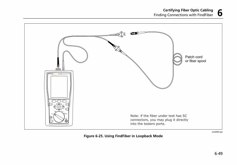
Certifying Fiber Optic Cabling Finding Connections with FindFiber 6
6-49
amd56f.eps
Figure 6-25. Using FindFiber in Loopback Mode
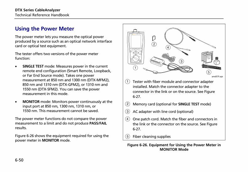
DTX Series CableAnalyzer Technical Reference Handbook
6-50
Using the Power Meter The power meter lets you measure the optical power produced by a source such as an optical network interface card or optical test equipment.
The tester offers two versions of the power meter function:
• SINGLE TEST mode: Measures power in the current remote end configuration (Smart Remote, Loopback, or Far End Source mode). Takes one power measurement at 850 nm and 1300 nm (DTX-MFM2), 850 nm and 1310 nm (DTX-GFM2), or 1310 nm and 1550 nm (DTX-SFM2). You can save the power measurement in this mode.
• MONITOR mode: Monitors power continuously at the input port at 850 nm, 1300 nm, 1310 nm, or 1550 nm. This measurement cannot be saved.
The power meter functions do not compare the power measurement to a limit and do not produce PASS/FAIL results.
Figure 6-26 shows the equipment required for using the power meter in MONITOR mode.
Wipe
C
A
D2
5 amd57f.eps
A Tester with fiber module and connector adapter installed. Match the connector adapter to the connector in the link or on the source. See Figure 6-27.
B Memory card (optional for SINGLE TEST mode)
C AC adapter with line cord (optional)
D One patch cord. Match the fiber and connectors in the link or the connector on the source. See Figure 6-27.
E Fiber cleaning supplies
Figure 6-26. Equipment for Using the Power Meter in MONITOR Mode
Certifying Fiber Optic Cabling Using the Power Meter 6
6-51
To use the power meter in MONITOR mode:
Note
If you need to save the power reading, use the power meter function in the SINGLE TEST mode.
1 Clean the tester’s input port, the reference test cord connectors, and the source connector.
2 Use the reference test cord to connect the source to the tester's input port, as shown in Figure 6-27.
3 Turn on the source.
4 Turn the rotary switch to MONITOR; then select Power Meter.
5 Press P.
6 Select the appropriate wavelength; then press P. The power meter in MONITOR mode runs continuously until you press I.
Figure 6-28 describes the power meter screens for SINGLE TEST and MONITOR modes.
amd126f.eps
Figure 6-27. Connections for Monitoring Optical Power (MONITOR mode)
DTX Series CableAnalyzer Technical Reference Handbook
6-52
To use the power meter in SINGLE TEST mode:
Note
Refer to previous sections on the Autotest in Smart Remote, Loopback, or Far End Source modes for details on selecting these modes and making test connections.
1 In SETUP, set the tester to Smart Remote, Loopback, or Far End Source mode.
2 Connect the tester to the cabling for Smart Remote, Loopback, or Far End Source mode.
3 Clean the tester’s input port, the reference test cord connectors, and the source connector(s).
4 Use the reference test cord(s) to connect to the cabling.
5 Turn on the source.
6 Turn the rotary switch to SINGLE TEST, select Power; then press P.
7 To save the results, press N, select or create a fiber ID; then press Nagain.
In Smart Remote mode you will save two power meter results, one for each fiber. In the saved results, Input Fiber and Output Fiber refer to the fibers connected to the main tester’s input and output ports at the end of the test.
Figure 6-28 describes the power meter screens for SINGLE TEST and MONITOR modes.
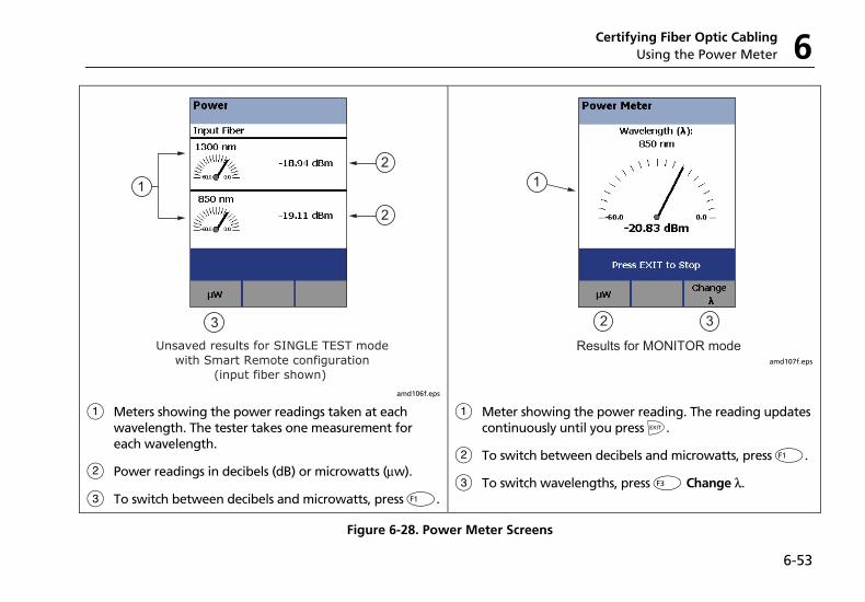
Certifying Fiber Optic Cabling Using the Power Meter 6
6-53
1
2
2
3Unsaved results for SINGLE TEST mode
with Smart Remote configuration(input fiber shown)
amd106f.eps
1
2 3
Results for MONITOR mode amd107f.eps
A Meters showing the power readings taken at each wavelength. The tester takes one measurement for each wavelength.
B Power readings in decibels (dB) or microwatts (µw).
C To switch between decibels and microwatts, press J.
A Meter showing the power reading. The reading updates continuously until you press I.
B To switch between decibels and microwatts, press J.
C To switch wavelengths, press L Change λ .
Figure 6-28. Power Meter Screens
DTX Series CableAnalyzer Technical Reference Handbook
6-54
Running Single Tests The tester’s SINGLE TEST mode lets you run individual tests for isolating cabling failures and quickly testing repairs.
In the SINGLE TEST mode, you can run and save the following tests individually:
• Loss
• Length (includes propagation delay)
• Power meter measurement
Using the Remote Tester with an OptiFiber Tester You can use a DTX Series smart remote with a DTX-MFM2 or DTX-SFM2 fiber module as the remote for a Fluke Networks OptiFiber Certifying OTDR. The DTX remote takes the place of a second OptiFiber tester for measuring loss and length with the OptiFiber loss/length option in Smart Remote mode. You can buy a smart remote separately for this purpose. See the Fluke Networks website or contact Fluke Networks for details.
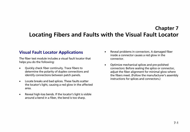
7-1
Chapter 7 Locating Fibers and Faults with the Visual Fault Locator
Visual Fault Locator Applications The fiber test module includes a visual fault locator that helps you do the following:
• Quickly check fiber continuity. Trace fibers to determine the polarity of duplex connections and identify connections between patch panels.
• Locate breaks and bad splices. These faults scatter the locator’s light, causing a red glow in the affected area.
• Reveal high-loss bends. If the locator’s light is visible around a bend in a fiber, the bend is too sharp.
• Reveal problems in connectors. A damaged fiber inside a connector causes a red glow in the connector.
• Optimize mechanical splices and pre-polished connectors: Before sealing the splice or connector, adjust the fiber alignment for minimal glow where the fibers meet. (Follow the manufacturer’s assembly instructions for splices and connectors.)
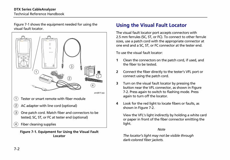
DTX Series CableAnalyzer Technical Reference Handbook
7-2
Figure 7-1 shows the equipment needed for using the visual fault locator.
Wipe
1
2
3
4
amd61f.eps
A Tester or smart remote with fiber module
B AC adapter with line cord (optional)
C One patch cord. Match fiber and connectors to be tested; SC, ST, or FC at tester end (optional)
D Fiber cleaning supplies
Figure 7-1. Equipment for Using the Visual Fault Locator
Using the Visual Fault Locator The visual fault locator port accepts connectors with 2.5 mm ferrules (SC, ST, or FC). To connect to other ferrule sizes, use a patch cord with the appropriate connector at one end and a SC, ST, or FC connector at the tester end.
To use the visual fault locator:
1 Clean the connectors on the patch cord, if used, and the fiber to be tested.
2 Connect the fiber directly to the tester’s VFL port or connect using the patch cord.
3 Turn on the visual fault locator by pressing the button near the VFL connector, as shown in Figure 7-2. Press again to switch to flashing mode. Press again to turn off the locator.
4 Look for the red light to locate fibers or faults, as shown in Figure 7-2.
View the VFL’s light indirectly by holding a white card or paper in front of the fiber connector emitting the light.
Note
The locator’s light may not be visible through dark-colored fiber jackets.
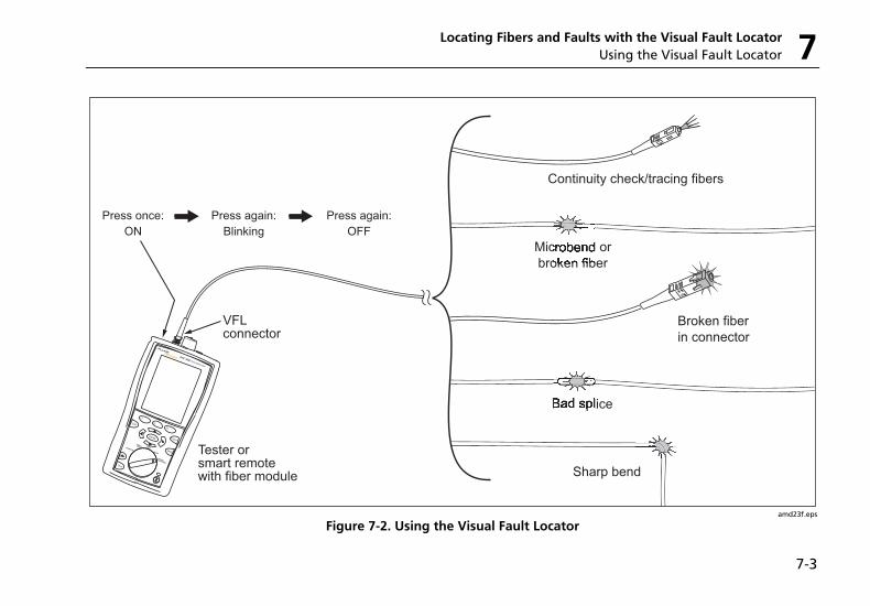
Locating Fibers and Faults with the Visual Fault Locator Using the Visual Fault Locator 7
7-3
amd23f.eps
Figure 7-2. Using the Visual Fault Locator

DTX Series CableAnalyzer Technical Reference Handbook
7-4
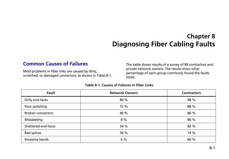
8-1
Chapter 8 Diagnosing Fiber Cabling Faults
Common Causes of Failures Most problems in fiber links are caused by dirty, scratched, or damaged connectors, as shown in Table 8-1.
The table shows results of a survey of 89 contractors and private network owners. The results show what percentage of each group commonly found the faults listed.
Table 8-1. Causes of Failures in Fiber Links
Fault Network Owners Contractors
Dirty end-faces 80 % 98 %
Poor polishing 72 % 88 %
Broken connectors 40 % 86 %
Mislabeling 8 % 86 %
Shattered end-faces 34 % 82 %
Bad splices 36 % 74 %
Excessive bends 6 % 66 %
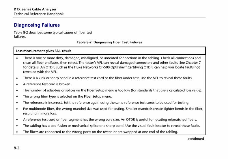
DTX Series Cable Analyzer Technical Reference Handbook
8-2
Diagnosing Failures Table 8-2 describes some typical causes of fiber test failures.
Table 8-2. Diagnosing Fiber Test Failures
Loss measurement gives FAIL result
• There is one or more dirty, damaged, misaligned, or unseated connections in the cabling. Check all connections and clean all fiber endfaces, then retest. The tester’s VFL can reveal damaged connectors and other faults. See Chapter 7 for details. An OTDR, such as the Fluke Networks OF-500 OptiFiber Certifying OTDR, can help you locate faults not revealed with the VFL.
• There is a kink or sharp bend in a reference test cord or the fiber under test. Use the VFL to reveal these faults.
• A reference test cord is broken.
• The number of adapters or splices on the Fiber Setup menu is too low (for standards that use a calculated loss value).
• The wrong fiber type is selected on the Fiber Setup menu.
• The reference is incorrect. Set the reference again using the same reference test cords to be used for testing.
• For multimode fiber, the wrong mandrel size was used for testing. Smaller mandrels create tighter bends in the fiber, resulting in more loss.
• A reference test cord or fiber segment has the wrong core size. An OTDR is useful for locating mismatched fibers.
• The cabling has a bad fusion or mechanical splice or a sharp bend. Use the visual fault locator to reveal these faults.
• The fibers are connected to the wrong ports on the tester, or are swapped at one end of the cabling.
-continued-
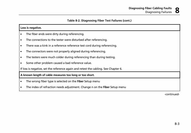
Diagnosing Fiber Cabling Faults Diagnosing Failures 8
8-3
Table 8-2. Diagnosing Fiber Test Failures (cont.)
Loss is negative.
• The fiber ends were dirty during referencing.
• The connections to the tester were disturbed after referencing.
• There was a kink in a reference reference test cord during referencing.
• The connectors were not properly aligned during referencing.
• The testers were much colder during referencing than during testing.
• Some other problem caused a bad reference value.
If loss is negative, set the reference again and retest the cabling. See Chapter 6.
A known length of cable measures too long or too short.
• The wrong fiber type is selected on the Fiber Setup menu
• The index of refraction needs adjustment. Change n on the Fiber Setup menu
-continued-
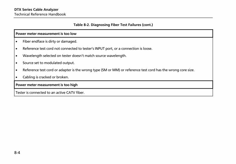
DTX Series Cable Analyzer Technical Reference Handbook
8-4
Table 8-2. Diagnosing Fiber Test Failures (cont.)
Power meter measurement is too low
• Fiber endface is dirty or damaged.
• Reference test cord not connected to tester’s INPUT port, or a connection is loose.
• Wavelength selected on tester doesn’t match source wavelength.
• Source set to modulated output.
• Reference test cord or adapter is the wrong type (SM or MM) or reference test cord has the wrong core size.
• Cabling is cracked or broken.
Power meter measurement is too high
Tester is connected to an active CATV fiber.
9-1
Chapter 9 Verifying Network Service
Overview of Features The optional DTX-NSM Network Service Module lets you do the following on twisted pair or fiber links:
• Verify connection to the network, including connection speed, duplex configuration, link wiring, and PoE service (wiring and PoE functions for twisted pair only)
• Ping IP addresses
• Monitor network traffic for utilization, collisions, errors, and broadcast packets
• Blink a port's activity LED
• Use Fluke Networks LinkRunner Cable ID locators (optional) to identify link connections at a patch panel (twisted pair only)
Notes
Running network tests on a fiber link requires an optional SFP module.
The DTX-NSM module does not support the Talk function.
Figure 9-1 describes the network module's features.
Software Requirements The following software supports the DTX-NSM module. Software upgrades are available on the Fluke Networks website.
• DTX software: version 1.3 or later
• LinkWare software: version 2.5 or later
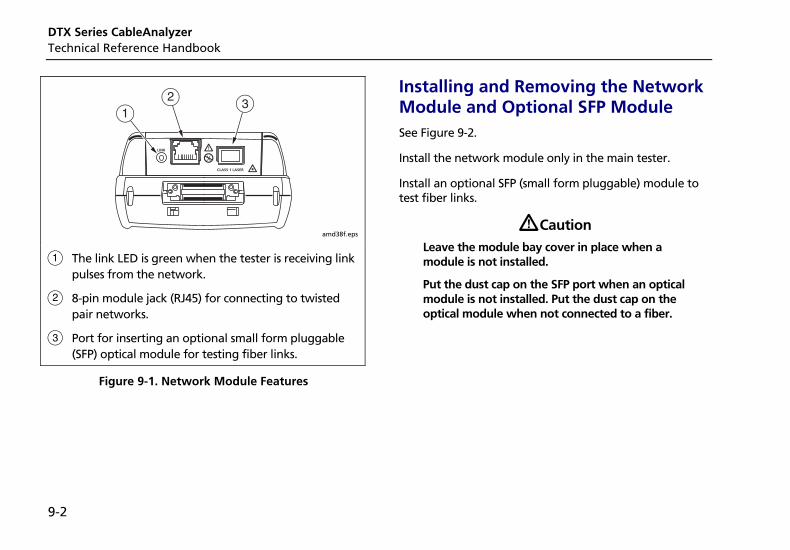
DTX Series CableAnalyzer Technical Reference Handbook
9-2
amd38f.eps
A The link LED is green when the tester is receiving link pulses from the network.
B 8-pin module jack (RJ45) for connecting to twisted pair networks.
C Port for inserting an optional small form pluggable (SFP) optical module for testing fiber links.
Figure 9-1. Network Module Features
Installing and Removing the Network Module and Optional SFP Module See Figure 9-2.
Install the network module only in the main tester.
Install an optional SFP (small form pluggable) module to test fiber links.
WCaution Leave the module bay cover in place when a module is not installed.
Put the dust cap on the SFP port when an optical module is not installed. Put the dust cap on the optical module when not connected to a fiber.
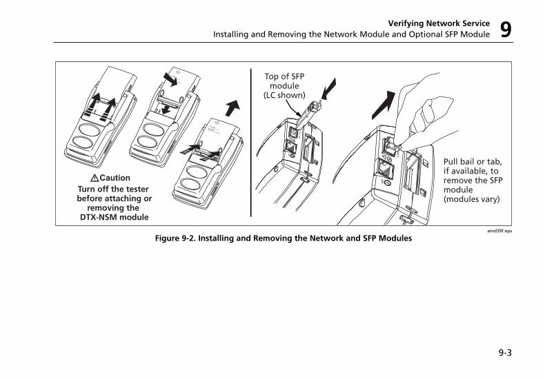
Verifying Network Service Installing and Removing the Network Module and Optional SFP Module 9
9-3
amd39f.eps
Figure 9-2. Installing and Removing the Network and SFP Modules
DTX Series CableAnalyzer Technical Reference Handbook
9-4
Verifying Network Connectivity The network connectivity test lets you verify that a twisted pair or fiber link is connected to a network. The test provides details about the link's configuration and includes a ping function for verifying connectivity to stations on the network.
Network Connectivity Test Settings
The tester needs various addresses to test a network connection, as described in Table 9-1. To access these settings, turn the rotary switch to SETUP; then select Network Settings.
Table 9-1. Network Connectivity Test Settings
Setting Description
SETUP > Network Settings > IP Address Assignment
Select DHCP (Dynamic Host Configuration Protocol) to have the network's server assign the tester's address, gateway address, and DHCP and DNS (Domain Name System) server addresses. Most networks support DHCP.
Select Static to enter the tester's address, subnet mask, gateway address, and DNS server address manually. Enter the addresses on the second tab that appears after you select Static. These addresses are typically available from a network installer, administrator, technician, or from network documentation.
WCaution In Static mode, verify that the DTX Address is not used by another network device. Using a duplicate address can cause the other device to malfunction.
SETUP > Network Settings > Target Addresses
Optional. Enter one or more addresses for ping tests. You may enter addresses manually, or download them from LinkWare software. See "Entering Ping Addresses" on page 9-5 for details.
Verifying Network Service Verifying Network Connectivity 9
9-5
Entering Ping Addresses
You can use LinkWare software to create and download ping addresses to the tester, or you can enter and edit addresses directly on the tester.
To use LinkWare to enter ping addresses:
1 Install the latest version of LinkWare software on your PC.
2 Select Utilities > DTX Utilities > Ping Target List on the LinkWare menu.
3 Create an address list; then download it to the tester. See the LinkWare online help for details.
To enter or edit ping addresses on the tester:
1 Turn the rotary switch to SETUP; then select Network Settings.
2 Select Target Addresses; then do one of the following:
• To add an address, press J Create. Enter a device Name and IP Address. Press N when you are finished.
• To edit an address, highlight the address name; then press L Edit. Select Name or IP Address for editing. Press N when you are finished.
• To delete an address, highlight the address name, press K Delete; then press L Yes.
DTX Series CableAnalyzer Technical Reference Handbook
9-6
Running the Connectivity Test
To test for network connectivity:
Note
The network connectivity test will not run on links with ground loops, analog telephone voltages, ISDN voltages, or other voltages (except PoE voltage). The tester warns you if it detects these conditions.
1 Select DHCP or Static mode and enter ping addresses in Setup, as described on pages 9-4 and 9-5.
2 Connect to the network as shown in Figure 9-3.
3 Turn the rotary switch to MONITOR; then select Network Connectivity.
4 Press P. Figure 9-4 describes the network connectivity results.
Saving Connectivity Results
You can save the network connectivity results in a separate record or with an existing cable test record.
To save the results in a separate record:
1 Run the network connectivity test, then press N.
2 Select Save Standalone Result. Create an ID; then press N again.
To save the results with an existing cable test record:
Note
You can add network connectivity results only to results for cables of the same type.
1 Run the network connectivity test, then press N.
2 Select Add to Cable Test Result.
3 Highlight the record you want to save the results with; then press K Add.
Verifying Network Service Verifying Network Connectivity 9
9-7
amd17f.eps
Figure 9-3. Network Test Connections
DTX Series CableAnalyzer Technical Reference Handbook
9-8
43
2
89
6
1
5
7
amd06.eps
A Speeds supported by the switch or hub: 10 Mbit, 100 Mbit, 1000 Mbit. The current speed is green. Arrows show the connection's duplex configuration:
B PoE shows if the device appears to support Power over Ethernet. The tester requests power from suspected PoE devices. PoE is red if the device did not supply power during the test.
Fiber shows for a fiber link.
C Crossover indicator (twisted pair only):
• Green: either the cable is straight-through, or the cable is a crossover and the hub or switch crossed pairs 12-36 (MDI on the Negotiation Details screen).
• Orange: the tester compensated for a crossover cable by crossing pairs 12-36 (MDI-X on the Negotiation Details screen).
-continued-
Figure 9-4. Network Connectivity Results Screen (DHCP example for twisted pair)
Verifying Network Service Verifying Network Connectivity 9
9-9
D Select Negotiation Details to see details. See Figure 9-5.
On the Negotiation Details screen, Yes for Pin Reversal indicates a reversed pair on the link, (such as wires 1 and 2 crossed). Run a wire map test on the link to check the wiring.
E Select DTX Address to see details, including the subnet mask.
F Network addresses used during the test:
• Gateway: Address of the network device that joins networks using different protocols or passes data between networks.
• DHCP Server: Dynamic Host Configuration Protocol server address. Shown only in DHCP mode.
• DNS Server: Domain Name System server address.
In DHCP mode, the addresses above show as 0.0.0.0 if the DHCP server does not provide them.
To see ping results for the above devices, highlight a device; then press H. See Figure 9-6.
The checkmarks and Xs indicate how many replies the tester received to its three pings:
: Green: Ping replies received for all requests.
: Orange: At least one ping reply received.
: No ping replies received, indicating a problem with the connection.
G <Target Address name>: appears if you use L Ping to ping a device. See "Pinging Network Devices" on page 9-11.
H See "Monitoring Network Traffic" on page 9-12 and "Blinking a Port Light" on page 9-14.
I Press L Ping to ping devices. See "Entering Ping Addresses" on page 9-11 and "Pinging Network Devices" on page 9-11.
Figure 9-4. Network Connectivity Results Screen (DHCP example for twisted pair) (cont.)
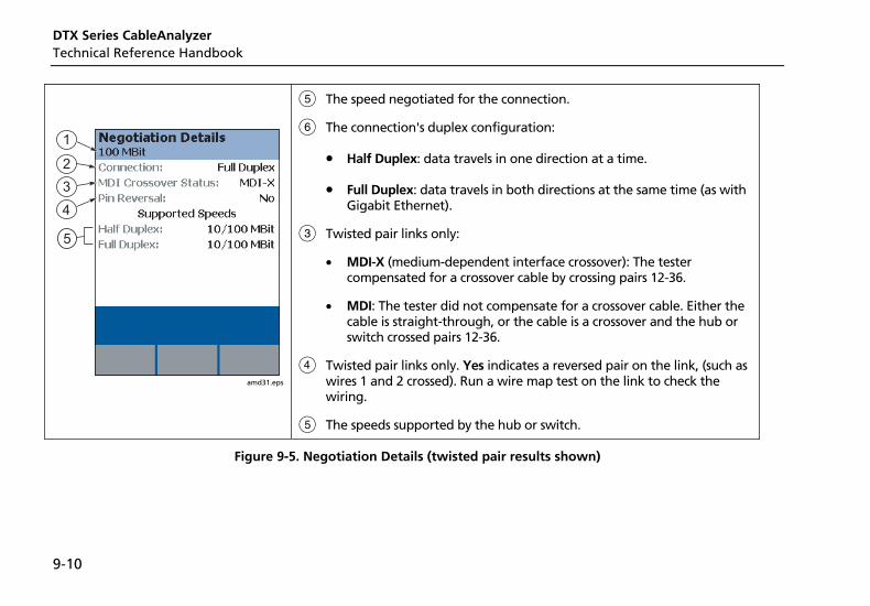
DTX Series CableAnalyzer Technical Reference Handbook
9-10
5
amd31.eps
E The speed negotiated for the connection.
F The connection's duplex configuration:
• Half Duplex: data travels in one direction at a time.
• Full Duplex: data travels in both directions at the same time (as with Gigabit Ethernet).
C Twisted pair links only:
• MDI-X (medium-dependent interface crossover): The tester compensated for a crossover cable by crossing pairs 12-36.
• MDI: The tester did not compensate for a crossover cable. Either the cable is straight-through, or the cable is a crossover and the hub or switch crossed pairs 12-36.
D Twisted pair links only. Yes indicates a reversed pair on the link, (such as wires 1 and 2 crossed). Run a wire map test on the link to check the wiring.
E The speeds supported by the hub or switch.
Figure 9-5. Negotiation Details (twisted pair results shown)
Verifying Network Service Pinging Network Devices 9
9-11
Pinging Network Devices The ping test verifies connectivity to devices on the network.
To ping a network device:
1 Enter ping addresses in Setup. See page 9-5.
2 Connect to the network as shown in Figure 9-3.
3 Turn the rotary switch to MONITOR, select Network Connectivity; then press P.
4 When the network connectivity test is complete, press L Ping.
5 Do one of the following:
• To ping one device, highlight the device; then press P.
• To ping all devices in the list, press JPing All.
The overall ping result appears on the Network Connectivity screen. A scroll bar appears if you pinged multiple devices
6 To see ping details (Figure 9-6), highlight a device; then press H.
7 To save the ping results, press N. Ping results are saved as part of the connectivity results. You can save the network connectivity results in a separate record or with an existing cable test record. See page 9-6.
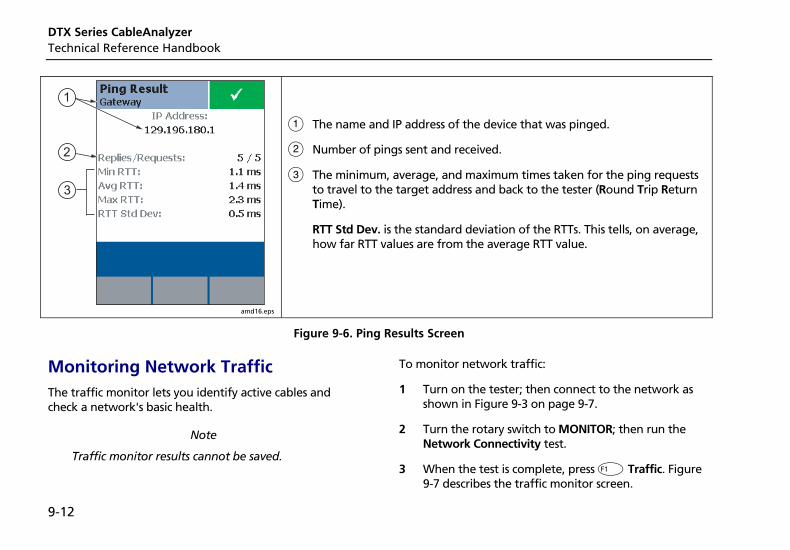
DTX Series CableAnalyzer Technical Reference Handbook
9-12
1
2
3
amd16.eps
A The name and IP address of the device that was pinged.
B Number of pings sent and received.
C The minimum, average, and maximum times taken for the ping requests to travel to the target address and back to the tester (Round Trip Return Time).
RTT Std Dev. is the standard deviation of the RTTs. This tells, on average, how far RTT values are from the average RTT value.
Figure 9-6. Ping Results Screen
Monitoring Network Traffic The traffic monitor lets you identify active cables and check a network's basic health.
Note
Traffic monitor results cannot be saved.
To monitor network traffic:
1 Turn on the tester; then connect to the network as shown in Figure 9-3 on page 9-7.
2 Turn the rotary switch to MONITOR; then run the Network Connectivity test.
3 When the test is complete, press J Traffic. Figure 9-7 describes the traffic monitor screen.
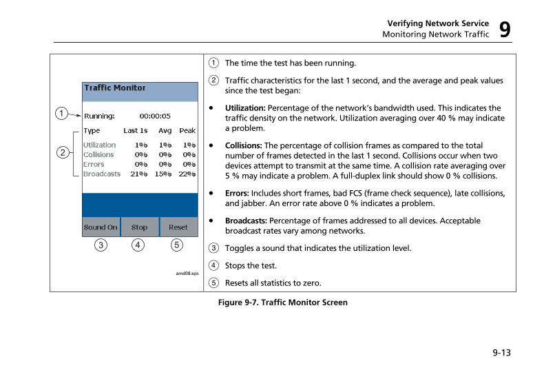
Verifying Network Service Monitoring Network Traffic 9
9-13
2
543
1
amd08.eps
A The time the test has been running.
B Traffic characteristics for the last 1 second, and the average and peak values since the test began:
• Utilization: Percentage of the network’s bandwidth used. This indicates the traffic density on the network. Utilization averaging over 40 % may indicate a problem.
• Collisions: The percentage of collision frames as compared to the total number of frames detected in the last 1 second. Collisions occur when two devices attempt to transmit at the same time. A collision rate averaging over 5 % may indicate a problem. A full-duplex link should show 0 % collisions.
• Errors: Includes short frames, bad FCS (frame check sequence), late collisions, and jabber. An error rate above 0 % indicates a problem.
• Broadcasts: Percentage of frames addressed to all devices. Acceptable broadcast rates vary among networks.
C Toggles a sound that indicates the utilization level.
D Stops the test.
E Resets all statistics to zero.
Figure 9-7. Traffic Monitor Screen
DTX Series CableAnalyzer Technical Reference Handbook
9-14
Blinking a Port Light The Port Blink function helps you quickly locate a link's port at a switch or hub. This function generates a link pulse on pairs 12 and 36 to blink the port's activity LED.
To blink a port light:
1 Connect to the network as shown in Figure 9-3 on page 9-7.
2 Turn the rotary switch to MONITOR, select Network Connectivity; then press P.
3 When the test is complete, press K Port Blink. A square on the hub/switch icon on the Network Connectivity screen blinks when the port blink function is active.
4 Look for a blinking activity LED on the hub or switch.
Identifying Links (twisted pair only) The ID Locator function helps you quickly identify link connections at a patch panel. This function requires one or more optional Fluke Networks LinkRunner Cable ID locators.
Note
ID locator results cannot be saved.
To identify a link:
1 Connect the tester and ID locator(s) as shown in Figure 9-8.
2 Turn the rotary switch to MONITOR, select ID Locator; then press P.
3 Connect the tester to different jacks, pressing P to rescan each time, until Found Cable ID and the identifier's number appears.
Note
Wiring faults may cause the tester to misidentify the ID locator's number, or prevent the tester from detecting the locator.
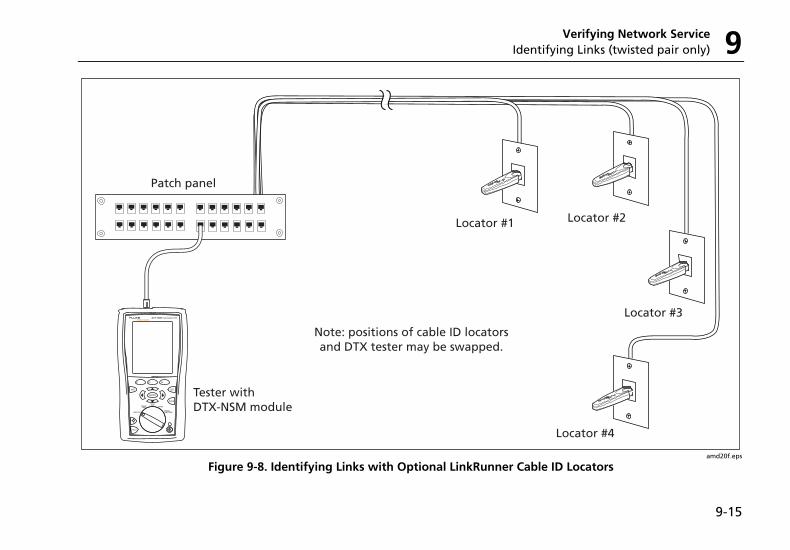
Verifying Network Service Identifying Links (twisted pair only) 9
9-15
amd20f.eps
Figure 9-8. Identifying Links with Optional LinkRunner Cable ID Locators
DTX Series CableAnalyzer Technical Reference Handbook
9-16
Diagnosing Low-Level Network Problems The DTX-NSM module helps you troubleshoot links and diagnose network problems up through layer 3 of the OSI (Open Systems Interconnect) 7-layer model. It can
also indicate problems at higher levels. Higher-level problems are usually addressed by a network technician or administrator using a network tester or analyzer.
Table 9-2 lists common causes of symptoms you can detect with the DTX-NSM module.
Table 9-2. Diagnosing Low-Level Network Problems
No ping response, limited responses, or ping times seem high
Note
To evaluate ping times, you should compare current results with results taken when the network was operating normally.
• Wiring fault on the link.
• Device is turned off.
• For static IP address assignment, incorrect address or subnet mask in Setup.
• A network fault, condition (such as network congestion), or security setting is preventing the device from answering.
• Since ping requests are low-priority traffic, devices may not respond to all requests.
-continued-
Verifying Network Service Diagnosing Low-Level Network Problems 9
9-17
Table 9-2. Diagnosing Low-Level Network Problems (cont.)
Wire pairs 12 and 36 are reversed
• Mix of 568A and 568B wiring standards.
• Crossover cables used where not needed. They are typically used only between two switches or hubs.
• Tester is connected to a NIC (network interface card) with a straight-through cable. The reversed result is normal in this situation., since a NIC transmits on pair 12 while a switch or hub transmits on 36.
Note
The utilization, collision, and error percentages given below are only guidelines. Acceptable percentages can vary among networks.
Utilization averaging above 40 %
Too many stations on the network.
Utilization spikes above 40 %
Broadcast storms.
-continued-
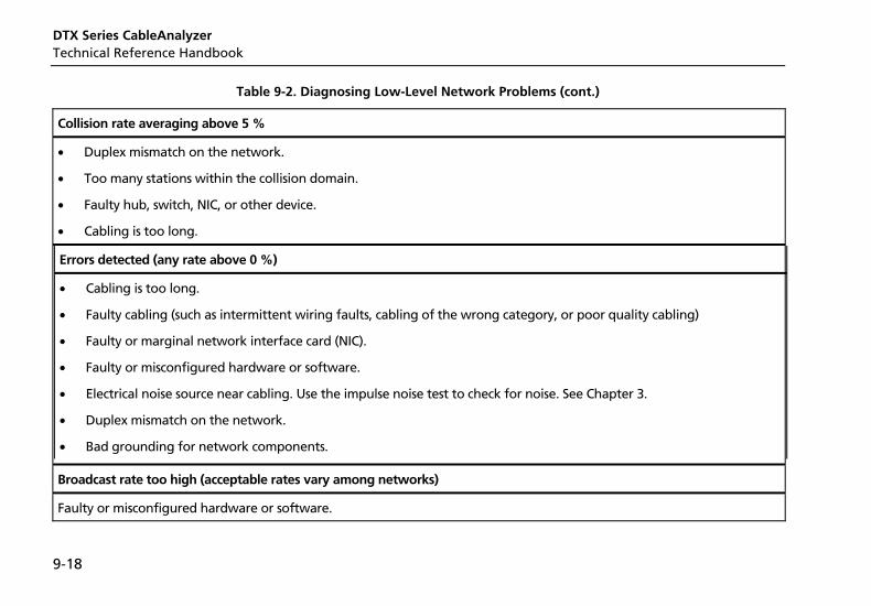
DTX Series CableAnalyzer Technical Reference Handbook
9-18
Table 9-2. Diagnosing Low-Level Network Problems (cont.)
Collision rate averaging above 5 %
• Duplex mismatch on the network.
• Too many stations within the collision domain.
• Faulty hub, switch, NIC, or other device.
• Cabling is too long.
Errors detected (any rate above 0 %)
• Cabling is too long.
• Faulty cabling (such as intermittent wiring faults, cabling of the wrong category, or poor quality cabling)
• Faulty or marginal network interface card (NIC).
• Faulty or misconfigured hardware or software.
• Electrical noise source near cabling. Use the impulse noise test to check for noise. See Chapter 3.
• Duplex mismatch on the network.
• Bad grounding for network components.
Broadcast rate too high (acceptable rates vary among networks)
Faulty or misconfigured hardware or software.
10-1
Chapter 10 Custom Test Settings
You can customize the following test settings:
• Twisted pair cable types
• Fiber optic cable types
• Twisted pair test limits
• Fiber optic test limits
• Outlet configurations for twisted pair cable
• NVP for twisted pair or coaxial cable
Creating a Custom Twisted Pair Cable Type You can create up to nine custom twisted pair cable types. A custom twisted pair cable type includes the following settings:
• Custom cable name
• Baseline cable type for default values
• Nominal velocity of propagation (NVP)
DTX Series CableAnalyzer Technical Reference Handbook
10-2
To create a custom twisted pair cable type:
1 Turn the rotary switch to SETUP; then select Twisted Pair.
2 Select Cable Type; then select Custom.
3 Press J Create.
4 On the Custom screen, select Name; then use the text editing screen to enter a name for your custom cable type. Press N when you are done.
5 On the Custom screen, select Use Default Values From, select a cable group; then select a cable type as a baseline for your custom cable type.
6 To change the NVP for your custom cable, select NVP on the Custom screen. You may set the NVP to a specified value, or determine the actual NVP of a sample of cable. See "Changing the NVP" on page 10-8.
7 From the Custom screen, press N when you are done creating the cable type.
The tester saves the custom cable type in the Custom list, with asterisks (*) before and after the name.
Custom Test Settings Creating a Custom Fiber Type10
10-3
Creating a Custom Fiber Type You can create up to nine custom fiber types. A custom fiber type includes the following settings:
• Custom fiber name
• Baseline limit for default settings
• Index of refraction (n)
To create a custom fiber type:
1 Turn the rotary switch to SETUP; then select Fiber.
2 Select Fiber Type; then select Custom.
3 Press J Create.
4 On the Custom screen, select Name; then use the text editing screen to enter a name for your custom fiber type. Press N when you are done.
5 On the Custom screen, select Use Default Values From, select a fiber group; then select a fiber type as a baseline for your custom fiber type.
6 To change the index of refraction (n) for your custom fiber, select n for a wavelength; then use the editing screen to enter a value for n. Press N when you are done.
7 From the Custom screen, press N when you are done creating the fiber type.
The tester saves the custom fiber type in the Custom list, with asterisks (*) before and after the name.
DTX Series CableAnalyzer Technical Reference Handbook
10-4
Creating a Custom Twisted Pair Test Limit You can create up to nine custom twisted pair test limits. A custom twisted pair test limit includes the following settings:
• Custom limit name
• Baseline limit for default settings
• Maximum length
• Resistance test enabled or disabled
• Insertion loss test enabled or disabled
• NEXT test enabled or disabled
• PSNEXT test enabled or disabled
• ELFEXT test enabled or disabled
• PSELFEXT test enabled or disabled
• ACR test enabled or disabled
• PSACR test enabled or disabled
• Return loss test enabled or disabled
To create a custom twisted pair limit:
1 Turn the rotary switch to SETUP; then select Twisted Pair.
2 Select Test Limit, press J More; then select Custom.
3 Press J Create.
4 On the Custom screen, select Name; then use the text editing screen to enter a name for your custom limit. Press N when you are done.
5 On the Custom screen, select Use Default Values From, select a test limit group; then select a limit as a baseline for your custom limit.
6 The Custom screen shows other settings on multiple tabs for the twisted pair limit. Use AD and H to select settings to change. Use BC to move among the tabs.
See Chapter 3 for details on twisted pair test parameters.
7 From the Custom screen, press N when you are done creating the limit.
The tester saves the custom limit in the Custom list, with asterisks (*) before and after the name.
Custom Test Settings Creating a Custom Fiber Limit10
10-5
Creating a Custom Fiber Limit You can create up to nine custom fiber limits. A custom fiber limit includes the following settings:
• Custom limit name
• Baseline limit for default values
• Maximum fiber length
• Maximum loss at the wavelengths required by the baseline limit.
To create a custom fiber limit:
1 Turn the rotary switch to SETUP; then select Fiber.
2 Select Test Limit, press J More; then select Custom.
3 Press J Create.
4 On the Custom screen, select Name; then use the text editing screen to enter a name for your custom fiber limit. Press N when you are done.
5 On the Custom screen, select Use Default Values From, select a limit group; then select a fiber limit as a baseline for your custom limit.
6 The Custom screen shows other settings on multiple tabs for the fiber test limit. Use AD and H to select settings to change. Use BC to move among the tabs.
See Chapter 6 for details on fiber test parameters.
7 From the Custom screen, press N when you are done creating the fiber type.
The tester saves the custom limit in the Custom list, with asterisks (*) before and after the name.
DTX Series CableAnalyzer Technical Reference Handbook
10-6
Creating a Custom Outlet Configuration You can create up to nine custom outlet configurations. A custom outlet configuration includes the following settings:
• Custom outlet name
• Baseline outlet configuration for default settings
• Enable/disable setting for each wire pair
To create a custom outlet configuration:
1 Turn the rotary switch to SETUP; then select Twisted Pair.
2 Select Outlet Configuration; then select Custom.
3 Press J Create.
4 On the Custom screen, select Name; then use the text editing screen to enter a name for your custom configuration. Press N when you are done.
5 On the Custom screen, select Use Default Values From; then select an outlet configuration as a baseline for your custom configuration.
6 On the Custom screen use AD and H to select wire pairs to enable or disable.
If the baseline configuration has additional wire pairs, use BC to move among the tabs.
7 From the Custom screen, press N when you are done creating the outlet configuration.
The tester saves the custom configuration in the Custom list, with asterisks (*) before and after the name.
Custom Test Settings Editing Custom Settings10
10-7
Editing Custom Settings The editing function lets you change values in existing custom settings.
To edit an existing custom cable, fiber type, test limit, or outlet configuration:
1 Turn the rotary switch to SETUP; then select Twisted Pair or Fiber.
2 On the Twisted Pair or Fiber menu, select the item that includes the custom settings you want to edit (Cable Type , Fiber Type, Test Limit, Outlet Configuration).
3 If you selected Test Limit, press J More.
4 Select Custom.
5 Use AD to highlight a custom setting; then press L Edit.
6 Make your changes on the Custom screen; then press N.
Deleting Custom Settings To delete a custom cable, fiber type, test limit, or outlet configuration:
1 Turn the rotary switch to SETUP; then select Twisted Pair or Fiber.
2 On the Twisted Pair or Fiber menu, select the item that includes the custom settings you want to delete (Cable Type , Fiber Type, Test Limit, or Outlet Configuration).
3 If you selected Test Limit, press J More.
4 Select Custom.
5 Use AD to highlight a custom setting.
6 Press K Delete; then press L Yes.
DTX Series CableAnalyzer Technical Reference Handbook
10-8
Changing the NVP The tester uses an NVP value (nominal velocity of propagation) and the signal delay through cable to calculate the length of twisted pair and coaxial cabling.
The default value defined by the selected cable type represents the typical NVP for that cable type. These values are usually accurate enough for certifying cable; however, you can increase the accuracy of length measurements by adjusting the NVP to a specified or actual value.
Note
NVP values can vary among cable types, lots, and manufacturers. In most cases, these differences are minor and may be disregarded.
Setting the NVP to a Specified Value
This procedure lets you set the NVP to a specified value, such as the value specified by the manufacturer. The NVP value applies to the selected cable type.
To enter a specified NVP value:
1 If you are in the middle of creating a custom cable type, go to step 4.
2 Turn the rotary switch to SETUP.
3 Select Twisted Pair or Coax.
4 Do one of the following:
• To change the NVP for the selected cable type, select NVP on the Twisted Pair or Coax menu.
• To change the NVP for a custom twisted pair cable type, create a custom cable type or select one for editing; then select NVP on the Custom screen. See page 10-1 for details on creating custom cable types.
5 Use AD to change the NVP value; then press N.
Custom Test Settings Changing the NVP10
10-9
Determining a Cable's Actual NVP
You can determine a cable's actual NVP by adjusting the measured length to match a known length of cable. The NVP value applies to the selected cable type.
To determine a cable's NVP:
1 If you are in the middle of creating a custom cable type, and a twisted pair or coaxial adapter is already attached to the tester, go to step 5.
2 Attach a twisted pair or coaxial adapter to the tester.
3 Turn the rotary switch to SETUP.
4 Select Twisted Pair or Coax.
5 Do one of the following:
• To change the NVP for the selected cable type, select NVP on the Twisted Pair or Coax menu.
• To change the NVP for a custom twisted pair cable type, create a custom cable type or select one for editing; then select NVP on the Custom screen. See page 10-1 for details on creating custom cable types.
6 Connect a known length of twisted pair or coaxial cable to the tester. The cable should be at least 30 m (100 ft) long.
7 Press P.
8 Use AD to change the NVP until the measured length matches the known length of the cable; then press N.
DTX Series CableAnalyzer Technical Reference Handbook
10-10
Resetting the NVP to the Default Value
You can reset the NVP to the default value defined by the selected cable type by re-selecting the cable type in SETUP.
To reset the NVP to the default value:
1 Turn the rotary switch to SETUP; then select Twisted Pair or Coax.
2 On the Twisted Pair or Coax menu, select Cable Type.
3 If you selected Twisted Pair, select the cable group that contains the desired cable type.
4 Select a cable type on the Cable Type menu. The NVP value on the Twisted Pair or Coax screen returns to the value defined by the cable type.
Transferring Custom Settings Between Testers To transfer custom limits, cable types, outlet configurations, and fiber types between testers, use the Modify DTX Test Limits utility in LinkWare software. This utility lets you upload custom settings from a tester to a PC, then download the settings to other testers. See the LinkWare online help for details.
11-1
Chapter 11 Memory Functions
Storage Locations and Capacities All DTX Series testers can store up to 250 Cat 6 Autotest results, including graphical data, in internal memory.
The maximum capacity of internal memory depends on the space taken by the tester’s software.
The DTX-1800 and DTX-1200 can store up to 500 Cat 6 Autotest results, including graphical data, on a 16 MB removable memory card.
The DTX-1800 and DTX-1200 testers can use MultiMediaCard (MMC) or Secure Digital memory cards (SD).
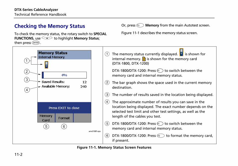
DTX-Series CableAnalyzer Technical Reference Handbook
11-2
Checking the Memory Status To check the memory status, the rotary switch to SPECIAL FUNCTIONS, use D to highlight Memory Status; then press H.
Or, press L Memory from the main Autotest screen.
Figure 11-1 describes the memory status screen.
1
2
3
4
5 6 amd108f.eps
A The memory status currently displayed. is shown for internal memory. is shown for the memory card (DTX-1800, DTX-1200)
DTX-1800/DTX-1200: Press A to switch between the memory card and internal memory status.
B The bar graph shows the space used in the current memory destination.
C The number of results saved in the location being displayed.
D The approximate number of results you can save in the location being displayed. The exact number depends on the selected test limit and other test settings, as well as the length of the cables you test.
E DTX-1800/DTX-1200: Press A to switch between the memory card and internal memory status.
F DTX-1800/DTX-1200: Press K to format the memory card, if present.
Figure 11-1. Memory Status Screen Features
Memory Functions Setting the Storage Location (DTX-1800, DTX-1200)11
11-3
Setting the Storage Location (DTX-1800, DTX-1200) To set the destination for saved results on a DTX-1800 or DTX-1200 tester:
1 Turn the rotary switch to SETUP.
2 Use D to highlight Instrument Settings; then press H.
3 Use D to highlight Result Storage Location; then press H.
4 Use D to highlight Internal Memory or Memory Card (if present); then press H.
Note
If you change the Result Storage Location, and the selected Current Folder does not exist in the new location, the tester creates a new folder with the current folder’s name in the new location.
Working with Folders You can create folders for each job to organize your test results. The tester saves test results in the folder you select.
Creating a New Folder
To create a new folder:
1 Turn the rotary switch to SETUP.
2 Use D to highlight Instrument Settings; then press H.
3 DTX-1800, DTX1200: Verify that the Result Storage Location shows the location where you want the new folder. Change the location if necessary.
4 On the Instrument Settings screen, use D to highlight Current Folder; then press H.
5 Press J Create Folder.
6 Use the softkeys, BCAD, and H to enter a folder name. Press N when you are finished.
DTX-Series CableAnalyzer Technical Reference Handbook
11-4
Changing Folders
To change the current folder:
1 Turn the rotary switch to SETUP.
2 Use D to highlight Instrument Settings; then press H.
3 DTX-1800, DTX1200: Verify that the Result Storage Location shows the correct location. Change the location if necessary.
4 On the Instrument Settings screen, use D to highlight Current Folder; then press H.
5 Use AD to highlight a folder name; then press H.
Note
Changing folders from the View Results screen in SPECIAL FUNCTIONS does not change the current folder in SETUP.
Deleting Folders
To delete a folder and all the results it contains:
1 Turn the rotary switch to SPECIAL FUNCTIONS.
2 Use D to highlight View/Delete Results; then press H.
3 If necessary, press J Change Folder to find the folder you want to delete.
4 Press K Delete.
5 Use D to highlight Current Folder; then press L Delete.
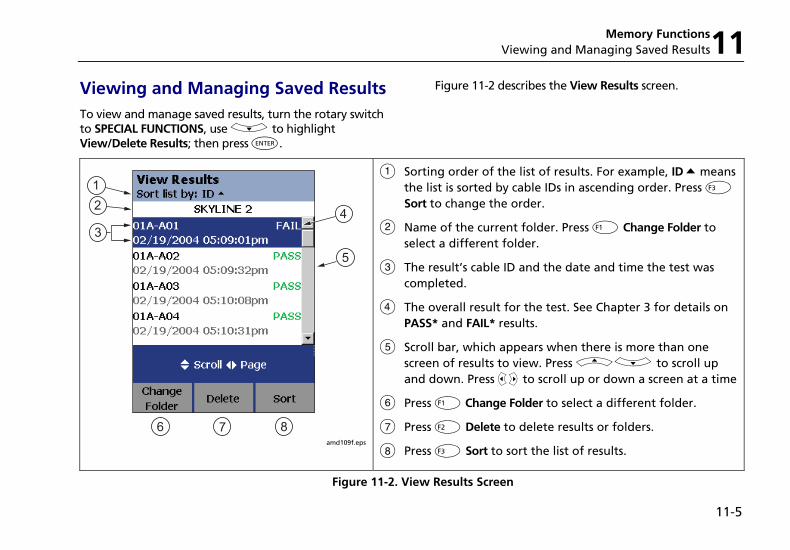
Memory Functions Viewing and Managing Saved Results11
11-5
Viewing and Managing Saved Results To view and manage saved results, turn the rotary switch to SPECIAL FUNCTIONS, use D to highlight View/Delete Results; then press H.
Figure 11-2 describes the View Results screen.
12
34
5
6 7 8 amd109f.eps
A Sorting order of the list of results. For example, ID Q means the list is sorted by cable IDs in ascending order. Press L Sort to change the order.
B Name of the current folder. Press J Change Folder to select a different folder.
C The result’s cable ID and the date and time the test was completed.
D The overall result for the test. See Chapter 3 for details on PASS* and FAIL* results.
E Scroll bar, which appears when there is more than one screen of results to view. Press AD to scroll up and down. Press BC to scroll up or down a screen at a time
F Press J Change Folder to select a different folder.
G Press K Delete to delete results or folders.
H Press L Sort to sort the list of results.
Figure 11-2. View Results Screen
DTX-Series CableAnalyzer Technical Reference Handbook
11-6
Moving or Copying Results to a Memory Card (DTX-1800, DTX-1200)
To move or copy all results from internal memory to the memory card:
1 Turn the rotary switch to SPECIAL FUNCTIONS.
2 Select Move/Copy Internal Results; then select an option:
• Move to Memory Card: Moves all results and their folders to the memory card and deletes all results from internal memory.
• Copy to Memory Card: Copies all results and their folders to the memory card.
• Delete from Internal Memory: Deletes all results from internal memory.
The tester displays a message if it cannot move or copy a result. This occurs in the following cases:
• A result with the same ID and timestamp already exists on the memory card.
• The memory card is full.
• The memory card is not formatted or is damaged.
Deleting Results
To delete results:
1 Turn the rotary switch to SPECIAL FUNCTIONS.
2 Use D to highlight View/Delete Results; then press H.
3 If necessary, press J Change Folder to find the result(s) you want to delete.
4 Press K Delete; then use D to highlight an option:
• Current Result: Deletes the result highlighted on the previous screen.
• All Results in Folder: Deletes all results in the current folder.
• All Results in Tester: Deletes all results in internal memory.
• Current Folder: Deletes the current folder and all its contents.
5 Press L Delete.
Memory Functions Formatting a Memory Card (DTX-1800, DTX-1200) or Internal Memory11
11-7
Sorting Results
You can sort the list of saved results in ascending or descending order by the following parameters:
• PASS/FAIL result
• Cable ID
• Date and time the test was completed
To sort results:
1 On the View Results screen, press L Sort.
2 Use D to highlight the field you want to sort by.
3 Press J Ascending or L Descending.
The sorting order applies only to the current folder. The current sorting order is indicated at the top of the View Results screen, as shown in Figure 11-2 on page 11-5
The default order is descending by date. The sorting order reverts to the default when you turn off the tester.
Formatting a Memory Card (DTX-1800, DTX-1200) or Internal Memory Formatting erases all contents of the memory card or internal memory.
To format a memory card or internal memory:
1 For a memory card, insert the card into the slot on the left side of the tester.
2 Turn the rotary switch to Autotest
3 Press L Memory.
4 For a DTX-1800 or DTX-1200 with a memory card installed, press J to select the memory card or internal memory.
5 Press K Format; then press L Yes.
DTX-Series CableAnalyzer Technical Reference Handbook
11-8
You can also format a memory card or internal memory in SPECIAL FUNCTIONS mode:
1 Turn the rotary switch to SPECIAL FUNCTIONS.
2 Use D to highlight Memory Status; then press H.
3 For a DTX-1800 or DTX-1200 with a memory card installed, press J to select the memory card or internal memory.
4 Press K Format; then press L Yes.
Memory Card Care (DTX-1800, DTX-1200) • Clean the card by wiping it with a slightly damp
cloth. If the card’s electrical contacts are dirty, use a pencil eraser to clean them.
• Keep the card out of direct sunlight and away from extreme heat or humidity.
• Do not drop the card on hard surfaces.
• Keep the card dry.
Memory Functions Uploading Results to a PC11
11-9
Uploading Results to a PC To upload results to a PC:
1 Install the latest version of LinkWare software on your PC.
2 Turn on the tester.
3 Connect the tester to the PC with the USB cable included or the DTX serial cable available from Fluke Networks.
or
Insert the memory card containing results into the PC’s memory card reader.
4 Start LinkWare software on the PC.
5 Click Import on the LinkWare toolbar. Select the tester’s model from the list.
or
Select Memory card or folder on PC.
6 Select the records you want to import; then click OK.
See the LinkWare online help for details on creating reports with LinkWare.

DTX-Series CableAnalyzer Technical Reference Handbook
11-10
12-1
Chapter 12 Maintenance and Specifications
Maintenance
WXWarning To avoid possible fire, electric shock, personal injury, or damage to the tester:
• Do not open the case. No user-serviceable parts are inside.
• Replacing electrical parts yourself will void the tester's warranty and might compromise its safety features.
• Use only specified replacement parts for user-replaceable items.
• Use only Fluke Networks authorized service centers.
WCaution Replacing electrical parts yourself might void the tester's calibration and compromise its accuracy. If the calibration is void, cable manufacturers might not extend their warranty to the cabling you install.
Reference Procedure for Link Interface Adapters
The reference procedure sets a baseline for various measurements. You should perform the reference procedure every 30 days or whenever you start using the tester with a different remote.
See “Setting the Reference” in Chapters 3 and 4 for details.
DTX Series CableAnalyzer Technical Reference Handbook
12-2
Factory Calibration
The tester requires calibration at a service center once a year to ensure that it meets or exceeds the published accuracy specifications. Contact an authorized Fluke Networks Service Center for information on getting your tester calibrated.
To see when the tester last received a service calibration, turn the rotary switch to SPECIAL FUNCTIONS; then select Version Information. The tester’s calibration date is also shown on reports uploaded to a PC.
Updating the Tester’s Software
Keeping your tester’s software current gives you access to new features and the latest test limits.
To get a software update, download the update from the Fluke Networks website or contact Fluke Networks to get the update by other means.
To see the software version installed in your main and remote testers, turn the rotary switch to SPECIAL FUNCTIONS; then select Version Information.
You can update your tester with a PC or with another tester that is already updated, as described in the following sections.
WCaution To avoid unexpected loss of power, connect the ac adapter to the tester when updating the software.
Note
Changes to the update procedure may be posted on the DTX CableAnalyzer software page on the Fluke Networks website.
Updating with a PC
1 Install the latest version of LinkWare software on your PC.
2 Download the DTX CableAnalyzer update file from the Fluke Networks website, or contact Fluke Networks to get the update by other means. You can access the software page at www.flukenetworks.com/support. Save the file to your hard drive.
3 Make the connections shown in Figure 9-3 using the USB or DTX serial cable. (The USB connection, if available, is faster.) Turn on the tester and the smart remote.
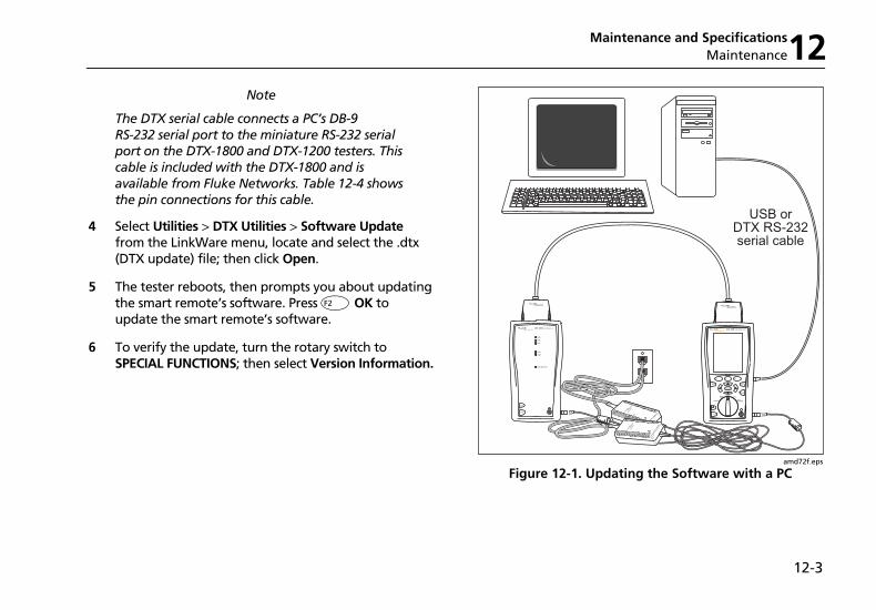
Maintenance and Specifications Maintenance12
12-3
Note
The DTX serial cable connects a PC’s DB-9 RS-232 serial port to the miniature RS-232 serial port on the DTX-1800 and DTX-1200 testers. This cable is included with the DTX-1800 and is available from Fluke Networks. Table 12-4 shows the pin connections for this cable.
4 Select Utilities > DTX Utilities > Software Update from the LinkWare menu, locate and select the .dtx (DTX update) file; then click Open.
5 The tester reboots, then prompts you about updating the smart remote’s software. Press K OK to update the smart remote’s software.
6 To verify the update, turn the rotary switch to SPECIAL FUNCTIONS; then select Version Information.
USB orDTX RS-232serial cable
TEST
LOW BATTERY
TONE
TALK
FAIL
TEST
PASS
TALK
TALK
MONITOR
ENTER
TEST
SAVE
SPECIAL FUNCTIONS
SETUP
AUTO TESTSINGLE
TEST
EXIT
F1 F2 F3
amd72f.eps
Figure 12-1. Updating the Software with a PC

DTX Series CableAnalyzer Technical Reference Handbook
12-4
Updating with Another Tester
You can update a tester’s software using another tester that is already updated.
1 Use link interface adapters to connect an updated tester or smart remote to a tester or smart remote that needs updating (Figure 9-4).
Note
One of the units must be a main tester.
2 Turn on both units; then press Pon either.
The testers compare software versions. If one has more recent software, the main tester prompts you about updating the older software.
3 Press K OK to start the update process.
4 To verify the update, turn the rotary switch to SPECIAL FUNCTIONS; then select Version Information.
PM06
TEST
LOW BATTERY
TONE
TALK
FAIL
TEST
PASS
TALKTALK
MONITOR
ENTER
TEST
SAVE
SPECIAL FUNCTIONS
SETUP
AUTO TESTSINGLE
TEST
EXIT
F1 F2 F3
PM06
TALK
MONITOR
ENTER
TEST
SAVE
SPECIAL FUNCTIONS
SETUP
AUTO TESTSINGLE
TEST
EXIT
F1 F2 F3
TALK
MONITOR
ENTER
TEST
SAVE
SPECIAL FUNCTIONS
SETUP
AUTO TESTSINGLE
TEST
EXIT
F1 F2 F3
amd73f.eps
Figure 12-2. Updating the Software with an Updated Tester
Maintenance and Specifications Maintenance12
12-5
Updating with a Memory Card (DTX-1800, DTX-1200)
You can update the tester’s software using a memory card that contains the software update file.
1 Download the DTX CableAnalyzer update file from the Fluke Networks website, or contact Fluke Networks to get the update by other means. You can access the software page at www.flukenetworks.com/support. Save the file to your hard drive.
2 Copy the software update file to a memory card.
3 Connect the tester and smart remote together using a permanent link and a channel adapter or two channel adapters and a patch cord. Turn on the tester and the smart remote.
4 Put the memory card in the tester.
5 Turn the rotary switch to SPECIAL FUNCTIONS; then select Update Software.
6 Press L Yes to start the update procedure.
7 When the tester is updated, it reboots, then prompts you about updating the smart remote’s software. Press K OK to update the smart remote’s software.
8 To verify the update, turn the rotary switch to SPECIAL FUNCTIONS; then select Version Information.
Updating the Limits or Cable Types Database
Fluke Networks may release a test limits or cable types database that is not part of a software update. To install a new database in your tester, use the Modify DTX Test Limits utility in LinkWare software. See the LinkWare online help for details.
DTX Series CableAnalyzer Technical Reference Handbook
12-6
Cleaning
Clean the display with glass cleaner or isopropyl alcohol and a soft, lint-free cloth. Clean the case with a soft cloth dampened with water or water and a mild soap.
WCaution To avoid damaging the display or the case, do not use solvents or abrasive cleansers.
Retraining the Battery Gauge
The accuracy of the battery gauge may drift over time if the battery is frequently recharged before being fully discharged. Retraining the battery gauge restores its accuracy.
Retraining can take 17 to 30 hours. The time is shorter if you start with the batteries discharged and modules (such as the fiber module) installed in the main and remote testers.
To retrain the battery gauge:
1 Connect the main and remote testers together using a permanent link adapter and a channel adapter, two channel adapters or two coaxial adapters and a patch cord, or two fiber modules and a reference test cord.
2 Connect the ac adapters to the main and remote testers. Turn on both testers.
3 Turn the rotary switch to SPECIAL FUNCTIONS; then select Battery Status. Verify that both the main and remote battery gauges are shown. If the remote gauge is missing, check the connections between the two units.
4 Press J Train Battery.
To abort the retraining, hold down the power key (M) on the main and remote testers until they turn off.
5 Retraining is complete when the testers have turned off and the LED by the ac adapter connection is green.
Maintenance and Specifications Maintenance12
12-7
Replacing the Battery
Replace the lithium ion battery pack when its life becomes noticeably shorter or when it fails to reach full charge. The battery is normally good for up to 400 charge/discharge cycles.
/Note
Dispose of the lithium ion battery pack in accordance with local regulations.
An internal lithium battery maintains the tester’s clock, when you remove the battery pack. This battery typically lasts about 5 years. When the battery begins to fail, the tester will lose the current date and time when you remove the battery pack. If the internal lithium battery fails, send the tester to a Fluke Networks service center for a replacement.
Fiber Module Maintenance
The following sections apply to the optional DTX-MFM2, DTX-GFM2, and DTX-SFM2 fiber modules.
Optical Connector and Adapter Care
Periodically clean and inspect the module’s optical connectors as described in Chapter 6.
Replacing Fiber Reference Test Cords
Choose replacement reference test cords that meet the following requirements:
• Core and cladding size: match the fiber to be tested
• Connector polish: PC or UPC
• Reference test cord length: minimum 2 m; maximum 5 m
To ensure optimum performance from your tester, get replacement cords from Fluke Networks.
DTX Series CableAnalyzer Technical Reference Handbook
12-8
Storage • Before storing the tester or an extra battery for an
extended period, charge the battery to between 70 % and 90 % of full charge. Check the battery every 4 months and recharge if necessary.
• Keep a battery attached to the tester during storage. Removing the battery for long periods shortens the life of the internal lithium battery that maintains the clock.
• See “Environmental and Regulatory Specifications” on page 12-15 for storage temperatures.
If Something Seems Wrong If something seems wrong with the tester, refer to Table 12-1.
If Table 12-1 does not help you solve a problem with the tester, contact Fluke Networks for additional help. See Chapter 1 for contact information.
If possible, have the tester’s serial number, software and hardware versions, and calibration date available. To see this information, turn the rotary switch to SPECIAL FUNCTIONS; then select Version Information.
For warranty information, refer to the warranty at the beginning of this manual. If the warranty has lapsed, contact Fluke Networks for repair prices.
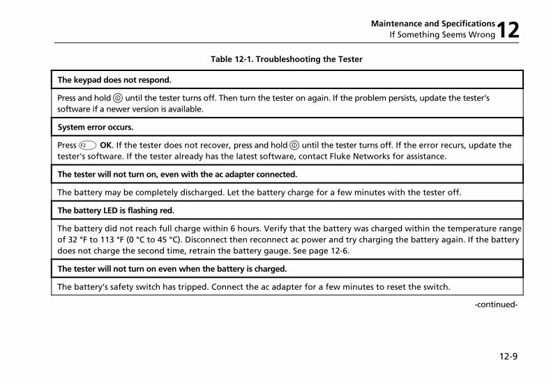
Maintenance and Specifications If Something Seems Wrong12
12-9
Table 12-1. Troubleshooting the Tester
The keypad does not respond.
Press and hold M until the tester turns off. Then turn the tester on again. If the problem persists, update the tester’s software if a newer version is available.
System error occurs.
Press K OK. If the tester does not recover, press and hold M until the tester turns off. If the error recurs, update the tester's software. If the tester already has the latest software, contact Fluke Networks for assistance.
The tester will not turn on, even with the ac adapter connected.
The battery may be completely discharged. Let the battery charge for a few minutes with the tester off.
The battery LED is flashing red.
The battery did not reach full charge within 6 hours. Verify that the battery was charged within the temperature range of 32 °F to 113 °F (0 °C to 45 °C). Disconnect then reconnect ac power and try charging the battery again. If the battery does not charge the second time, retrain the battery gauge. See page 12-6.
The tester will not turn on even when the battery is charged.
The battery’s safety switch has tripped. Connect the ac adapter for a few minutes to reset the switch.
-continued-

DTX Series CableAnalyzer Technical Reference Handbook
12-10
Table 12-1. Troubleshooting the Tester (cont.)
All the LEDs on the smart remote are flashing
The smart remote detects excessive voltage on the cable. Unplug the cable immediately.
Test results appear to be incorrect.
The tester may not be configured correctly. For example, the wrong test standard or cable type may be selected or the NVP may be incorrect.
The tester may need referencing. See Chapter 3 or 4 for details.
The reference test cords and adapters are good, but the reference power level is too low.
Clean the tester’s input and output connectors and use a fiber microscope to inspect the endfaces. If an endface is damaged, contact Fluke Networks for service information.
A fiber test produces a negative loss reading.
There is a problem with the reference. Set the reference and test the cabling again. See Chapters 6 and 8 for details.
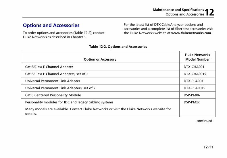
Maintenance and Specifications Options and Accessories12
12-11
Options and Accessories To order options and accessories (Table 12-2), contact Fluke Networks as described in Chapter 1.
For the latest list of DTX CableAnalyzer options and accessories and a complete list of fiber test accessories visit the Fluke Networks website at www.flukenetworks.com.
Table 12-2. Options and Accessories
Option or Accessory
Fluke Networks Model Number
Cat 6/Class E Channel Adapter DTX-CHA001
Cat 6/Class E Channel Adapters, set of 2 DTX-CHA001S
Universal Permanent Link Adapter DTX-PLA001
Universal Permanent Link Adapters, set of 2 DTX-PLA001S
Cat 6 Centered Personality Module DSP-PM06
Personality modules for IDC and legacy cabling systems
Many models are available. Contact Fluke Networks or visit the Fluke Networks website for details.
DSP-PMxx
-continued-
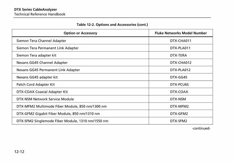
DTX Series CableAnalyzer Technical Reference Handbook
12-12
Table 12-2. Options and Accessories (cont.)
Option or Accessory Fluke Networks Model Number
Siemon Tera Channel Adapter DTX-CHA011
Siemon Tera Permanent Link Adapter DTX-PLA011
Siemon Tera adapter kit DTX-TERA
Nexans GG45 Channel Adapter DTX-CHA012
Nexans GG45 Permanent Link Adapter DTX-PLA012
Nexans GG45 adapter kit DTX-GG45
Patch Cord Adapter Kit DTX-PCU6S
DTX-COAX Coaxial Adapter Kit DTX-COAX
DTX-NSM Network Service Module DTX-NSM
DTX-MFM2 Multimode Fiber Module, 850 nm/1300 nm DTX-MFM2
DTX-GFM2 Gigabit Fiber Module, 850 nm/1310 nm DTX-GFM2
DTX-SFM2 Singlemode Fiber Module, 1310 nm/1550 nm DTX-SFM2
-continued-
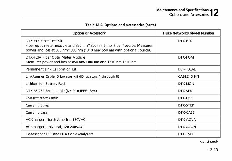
Maintenance and Specifications Options and Accessories12
12-13
Table 12-2. Options and Accessories (cont.)
Option or Accessory Fluke Networks Model Number
DTX-FTK Fiber Test Kit Fiber optic meter module and 850 nm/1300 nm SimpliFiber source. Measures power and loss at 850 nm/1300 nm (1310 nm/1550 nm with optional source).
DTX-FTK
DTX-FOM Fiber Optic Meter Module Measures power and loss at 850 nm/1300 nm and 1310 nm/1550 nm.
DTX-FOM
Permanent Link Calibration Kit DSP-PLCAL
LinkRunner Cable ID Locator Kit (ID locators 1 through 8) CABLE ID KIT
Lithium Ion Battery Pack DTX-LION
DTX RS-232 Serial Cable (DB-9 to IEEE 1394) DTX-SER
USB Interface Cable DTX-USB
Carrying Strap DTX-STRP
Carrying case DTX-CASE
AC Charger, North America, 120VAC DTX-ACNA
AC Charger, universal, 120-240VAC DTX-ACUN
Headset for DSP and DTX CableAnalyzers DTX-TSET
-continued-
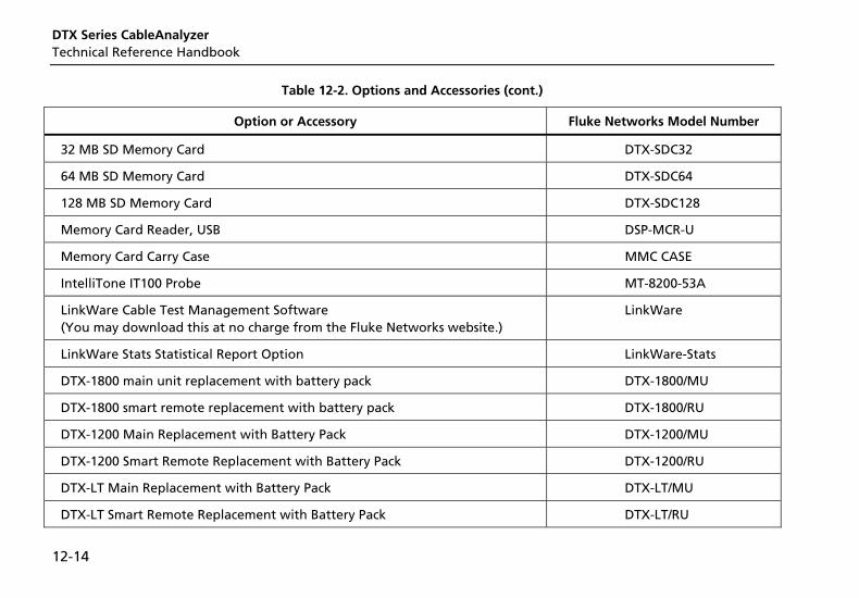
DTX Series CableAnalyzer Technical Reference Handbook
12-14
Table 12-2. Options and Accessories (cont.)
Option or Accessory Fluke Networks Model Number
32 MB SD Memory Card DTX-SDC32
64 MB SD Memory Card DTX-SDC64
128 MB SD Memory Card DTX-SDC128
Memory Card Reader, USB DSP-MCR-U
Memory Card Carry Case MMC CASE
IntelliTone IT100 Probe MT-8200-53A
LinkWare Cable Test Management Software (You may download this at no charge from the Fluke Networks website.)
LinkWare
LinkWare Stats Statistical Report Option LinkWare-Stats
DTX-1800 main unit replacement with battery pack DTX-1800/MU
DTX-1800 smart remote replacement with battery pack DTX-1800/RU
DTX-1200 Main Replacement with Battery Pack DTX-1200/MU
DTX-1200 Smart Remote Replacement with Battery Pack DTX-1200/RU
DTX-LT Main Replacement with Battery Pack DTX-LT/MU
DTX-LT Smart Remote Replacement with Battery Pack DTX-LT/RU
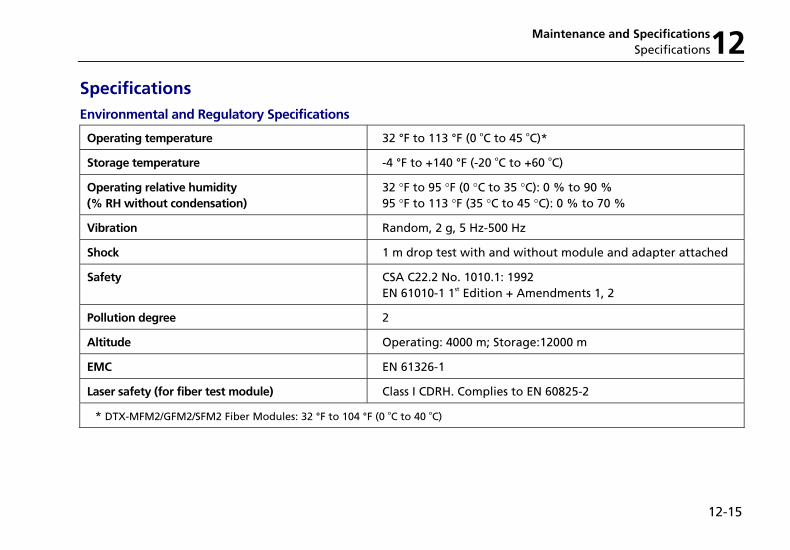
Maintenance and Specifications Specifications12
12-15
Specifications
Environmental and Regulatory Specifications
Operating temperature 32 °F to 113 °F (0 oC to 45 oC)*
Storage temperature -4 °F to +140 °F (-20 oC to +60 oC)
Operating relative humidity (% RH without condensation)
32 °F to 95 °F (0 °C to 35 °C): 0 % to 90 % 95 °F to 113 °F (35 °C to 45 °C): 0 % to 70 %
Vibration Random, 2 g, 5 Hz-500 Hz
Shock 1 m drop test with and without module and adapter attached
Safety CSA C22.2 No. 1010.1: 1992 EN 61010-1 1st Edition + Amendments 1, 2
Pollution degree 2
Altitude Operating: 4000 m; Storage:12000 m
EMC EN 61326-1
Laser safety (for fiber test module) Class I CDRH. Complies to EN 60825-2
* DTX-MFM2/GFM2/SFM2 Fiber Modules: 32 °F to 104 °F (0 oC to 40 oC)
DTX Series CableAnalyzer Technical Reference Handbook
12-16
WXWarning Under no circumstances is this product intended for direct connection to telephony inputs, systems, or equipment, including ISDN inputs. Doing so is a misapplication of this product, which could result in damage to the tester and create a potential shock hazard to the user.
Service Calibration Period
One year.
Standard Link Interface Adapters • Cat 6/Class E permanent link adapters
Plug type and life: shielded 8-pin modular (RJ45); >5000 insertions
Tests supported: shielded and unshielded cable, TIA Cat 3, 4, 5, 5e, and 6 and ISO/IEC Class C and D, and E permanent link
• Cat 6/Class E channel adapters
Plug type and life: shielded 8-pin modular (RJ45); >5000 insertions
Tests supported: shielded and unshielded cable, TIA Cat 3, 4, 5, 5e, and 6 and ISO/IEC Class C and D channels
Cable Types Tested
Shielded and unshielded twisted pair (STP, FTP, SSTP, and UTP) LAN cabling:
• TIA Category 3, 4, 5, 5e, and 6: 100 Ω
• ISO/IEC Class C and D: 100 Ω and 120 Ω
Note
For availability of additional adapters that allow testing to other performance standards, different cabling types, or fiber optic cabling, contact Fluke Networks.
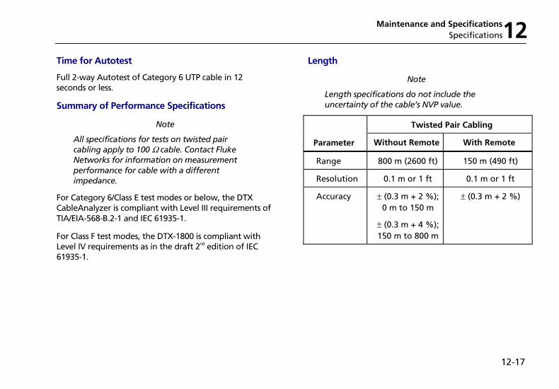
Maintenance and Specifications Specifications12
12-17
Time for Autotest
Full 2-way Autotest of Category 6 UTP cable in 12 seconds or less.
Summary of Performance Specifications
Note
All specifications for tests on twisted pair cabling apply to 100 Ω cable. Contact Fluke Networks for information on measurement performance for cable with a different impedance.
For Category 6/Class E test modes or below, the DTX CableAnalyzer is compliant with Level III requirements of TIA/EIA-568-B.2-1 and IEC 61935-1.
For Class F test modes, the DTX-1800 is compliant with Level IV requirements as in the draft 2nd edition of IEC 61935-1.
Length
Note
Length specifications do not include the uncertainty of the cable’s NVP value.
Twisted Pair Cabling
Parameter Without Remote With Remote
Range 800 m (2600 ft) 150 m (490 ft)
Resolution 0.1 m or 1 ft 0.1 m or 1 ft
Accuracy ± (0.3 m + 2 %); 0 m to 150 m
± (0.3 m + 4 %); 150 m to 800 m
± (0.3 m + 2 %)
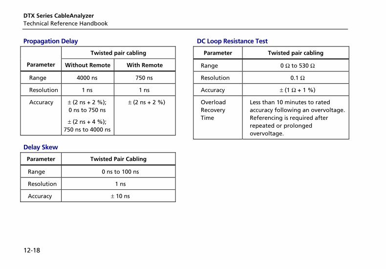
DTX Series CableAnalyzer Technical Reference Handbook
12-18
Propagation Delay
Twisted pair cabling
Parameter Without Remote With Remote
Range 4000 ns 750 ns
Resolution 1 ns 1 ns
Accuracy ± (2 ns + 2 %); 0 ns to 750 ns
± (2 ns + 4 %); 750 ns to 4000 ns
± (2 ns + 2 %)
Delay Skew
Parameter Twisted Pair Cabling
Range 0 ns to 100 ns
Resolution 1 ns
Accuracy ± 10 ns
DC Loop Resistance Test
Parameter Twisted pair cabling
Range 0 Ω to 530 Ω
Resolution 0.1 Ω
Accuracy ± (1 Ω + 1 %)
Overload Recovery Time
Less than 10 minutes to rated accuracy following an overvoltage. Referencing is required after repeated or prolonged overvoltage.
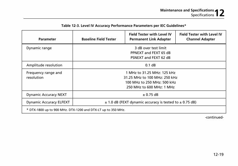
Maintenance and Specifications Specifications12
12-19
Table 12-3. Level IV Accuracy Performance Parameters per IEC Guidelines*
Parameter
Baseline Field Tester
Field Tester with Level IV Permanent Link Adapter
Field Tester with Level IV Channel Adapter
Dynamic range 3 dB over test limit PPNEXT and FEXT 65 dB PSNEXT and FEXT 62 dB
Amplitude resolution 0.1 dB
Frequency range and resolution
1 MHz to 31.25 MHz: 125 kHz 31.25 MHz to 100 MHz: 250 kHz 100 MHz to 250 MHz: 500 kHz 250 MHz to 600 MHz: 1 MHz
Dynamic Accuracy NEXT ± 0.75 dB
Dynamic Accuracy ELFEXT ± 1.0 dB (FEXT dynamic accuracy is tested to ± 0.75 dB)
* DTX-1800 up to 900 MHz. DTX-1200 and DTX-LT up to 350 MHz.
-continued-
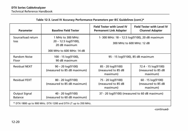
DTX Series CableAnalyzer Technical Reference Handbook
12-20
Table 12-3. Level IV Accuracy Performance Parameters per IEC Guidelines (cont.)*
Parameter
Baseline Field Tester
Field Tester with Level IV Permanent Link Adapter
Field Tester with Level IV Channel Adapter
Source/load return loss
1 MHz to 300 MHz: 20 – 12.5 log(f/100),
20 dB maximum
300 MHz to 600 MHz: 14 dB
1- 300 MHz: 18 – 12.5 log(f/100), 20 dB maximum
300 MHz to 600 MHz: 12 dB
Random Noise Floor
100 - 15 log(f/100), 90 dB maximum
95 - 15 log(f/100), 85 dB maximum
Residual NEXT 90 – 20 log(f/100) (measured to 85 dB maximum)
85 - 20 log(f/100) (measured to 85 dB
maximum)
72.4 - 15 log(f/100) (measured to 85 dB
maximum)
Residual FEXT 80 - 20 log(f/100) (measured to 85 dB maximum)
75 - 20 log(f/100) (measured to 85 dB
maximum)
60 - 15 log(f/100) (measured to 85 dB
maximum)
Output Signal Balance
40 - 20 log(f/100) (measured to 60 dB maximum)
37 - 20 log(f/100) (measured to 60 dB maximum)
* DTX-1800 up to 900 MHz. DTX-1200 and DTX-LT up to 350 MHz.
-continued-
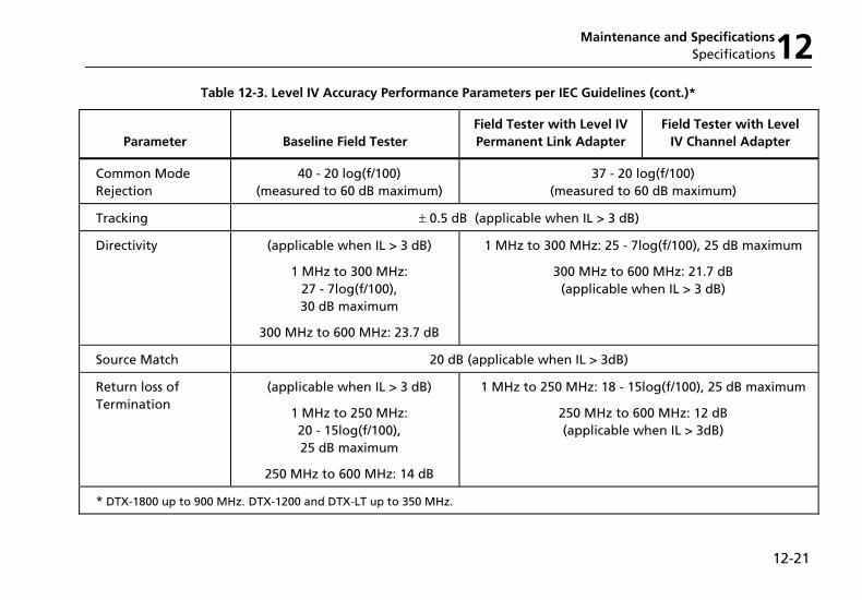
Maintenance and Specifications Specifications12
12-21
Table 12-3. Level IV Accuracy Performance Parameters per IEC Guidelines (cont.)*
Parameter
Baseline Field Tester
Field Tester with Level IV Permanent Link Adapter
Field Tester with Level IV Channel Adapter
Common Mode Rejection
40 - 20 log(f/100) (measured to 60 dB maximum)
37 - 20 log(f/100) (measured to 60 dB maximum)
Tracking ± 0.5 dB (applicable when IL > 3 dB)
Directivity (applicable when IL > 3 dB)
1 MHz to 300 MHz: 27 - 7log(f/100), 30 dB maximum
300 MHz to 600 MHz: 23.7 dB
1 MHz to 300 MHz: 25 - 7log(f/100), 25 dB maximum
300 MHz to 600 MHz: 21.7 dB (applicable when IL > 3 dB)
Source Match 20 dB (applicable when IL > 3dB)
Return loss of Termination
(applicable when IL > 3 dB)
1 MHz to 250 MHz: 20 - 15log(f/100), 25 dB maximum
250 MHz to 600 MHz: 14 dB
1 MHz to 250 MHz: 18 - 15log(f/100), 25 dB maximum
250 MHz to 600 MHz: 12 dB (applicable when IL > 3dB)
* DTX-1800 up to 900 MHz. DTX-1200 and DTX-LT up to 350 MHz.
DTX Series CableAnalyzer Technical Reference Handbook
12-22
Measurement Accuracy
The measurement accuracy of the DTX Series CableAnalyzer testers meets or exceeds accuracy Level IV. The DTX-1800 measures up to 900 MHz and is fully compliant with accuracy Level IV. The DTX-1200 and DTX-LT measure up to 350 MHz with accuracy Level IV performance.
Worst case accuracy performance parameters are used for asterisk (*) results reporting. These are based on computation of the overall measurement accuracy based
on the worst case of each parameter at each frequency data point. Observed differences between laboratory equipment and DTX CableAnalyzers using calibration verification artifacts were used as a confirmation.
Accuracies computed from the parameters in Table 12-3 are shown in Figures 12-3 through 9-6.
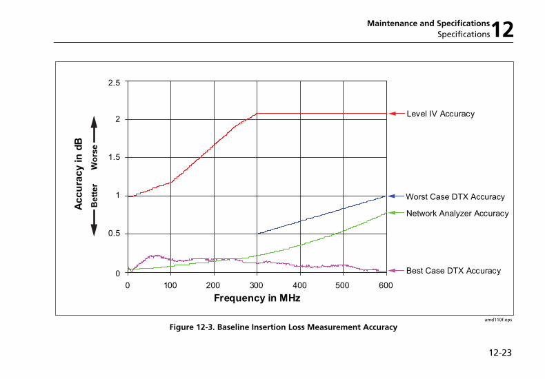
Maintenance and Specifications Specifications12
12-23
0
0.5
1
1.5
2
2.5
0 100 200 300 400 500 600
Frequency in MHz
Ac
cu
rac
y i
n d
B
Network Analyzer Accuracy
Level IV Accuracy
Best Case DTX Accuracy
Worst Case DTX Accuracy
Wo
rse
Be
tte
r
amd110f.eps
Figure 12-3. Baseline Insertion Loss Measurement Accuracy
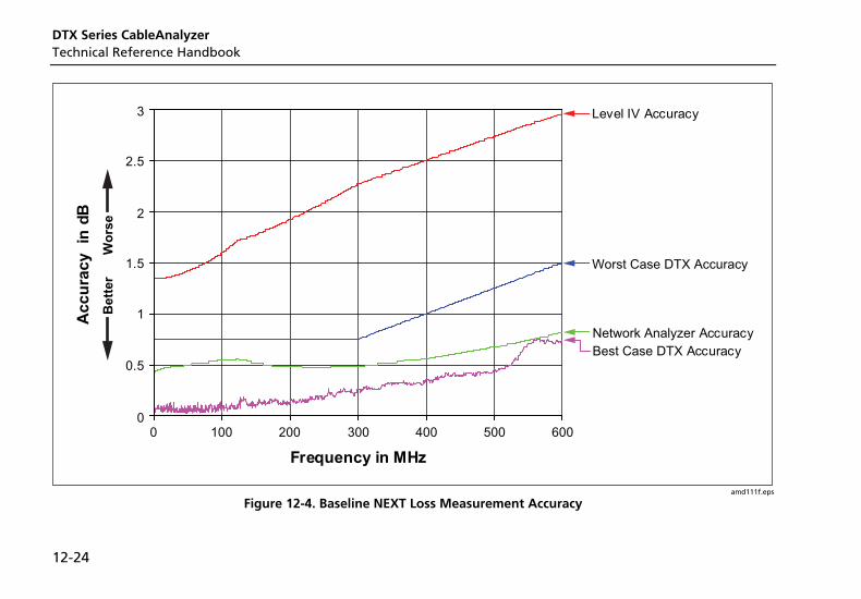
DTX Series CableAnalyzer Technical Reference Handbook
12-24
Frequency in MHz
Ac
cu
rac
y
in d
B
Network Analyzer Accuracy
Level IV Accuracy
Best Case DTX Accuracy
Worst Case DTX Accuracy
Wo
rse
Be
tte
r
0
0.5
1
1.5
2
2.5
3
0 100 200 300 400 500 600
amd111f.eps
Figure 12-4. Baseline NEXT Loss Measurement Accuracy
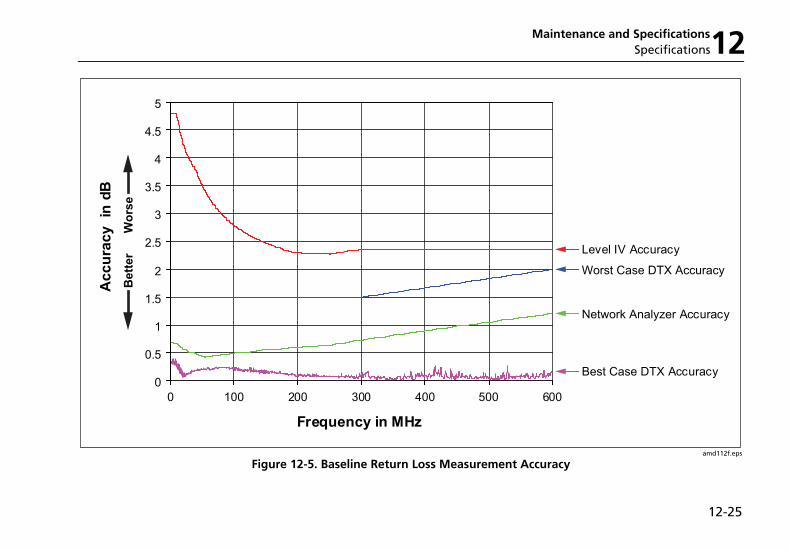
Maintenance and Specifications Specifications12
12-25
Frequency in MHz
Ac
cu
rac
y
in d
B
Network Analyzer Accuracy
Level IV Accuracy
Best Case DTX Accuracy
Worst Case DTX Accuracy
Wo
rse
Be
tte
r
0
0.5
1
1.5
2
2.5
3
3.5
4
4.5
5
0 100 200 300 400 500 600
amd112f.eps
Figure 12-5. Baseline Return Loss Measurement Accuracy
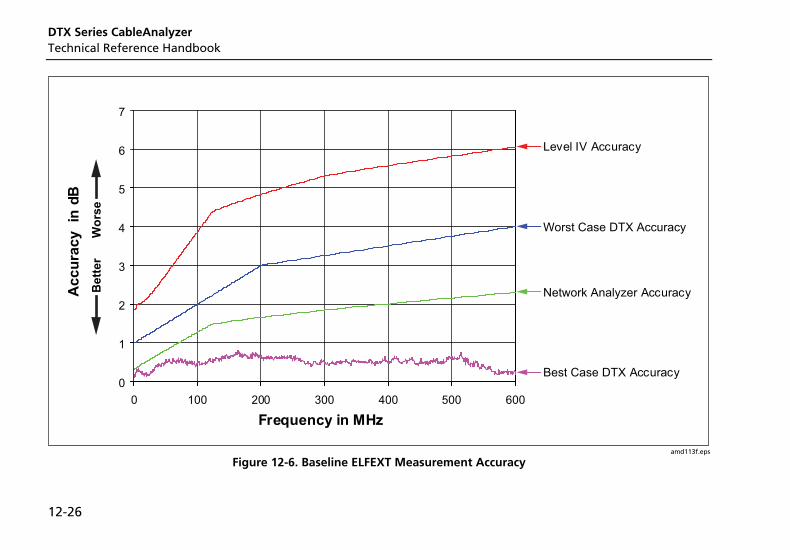
DTX Series CableAnalyzer Technical Reference Handbook
12-26
Frequency in MHz
Ac
cu
rac
y
in d
B
Network Analyzer Accuracy
Level IV Accuracy
Best Case DTX Accuracy
Worst Case DTX Accuracy
Wo
rse
Be
tte
r
0
1
2
3
4
5
6
7
0 100 200 300 400 500 600
amd113f.eps
Figure 12-6. Baseline ELFEXT Measurement Accuracy
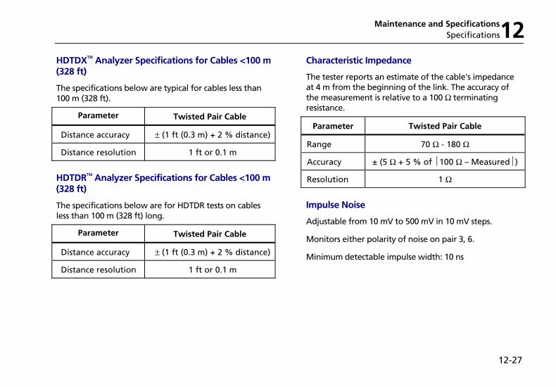
Maintenance and Specifications Specifications12
12-27
HDTDX Analyzer Specifications for Cables <100 m (328 ft)
The specifications below are typical for cables less than 100 m (328 ft).
Parameter Twisted Pair Cable
Distance accuracy ± (1 ft (0.3 m) + 2 % distance)
Distance resolution 1 ft or 0.1 m
HDTDR Analyzer Specifications for Cables <100 m (328 ft)
The specifications below are for HDTDR tests on cables less than 100 m (328 ft) long.
Parameter Twisted Pair Cable
Distance accuracy ± (1 ft (0.3 m) + 2 % distance)
Distance resolution 1 ft or 0.1 m
Characteristic Impedance
The tester reports an estimate of the cable's impedance at 4 m from the beginning of the link. The accuracy of the measurement is relative to a 100 Ω terminating resistance.
Parameter Twisted Pair Cable
Range 70 Ω - 180 Ω
Accuracy ± (5 Ω + 5 % of 100 Ω – Measured )
Resolution 1 Ω
Impulse Noise
Adjustable from 10 mV to 500 mV in 10 mV steps.
Monitors either polarity of noise on pair 3, 6.
Minimum detectable impulse width: 10 ns
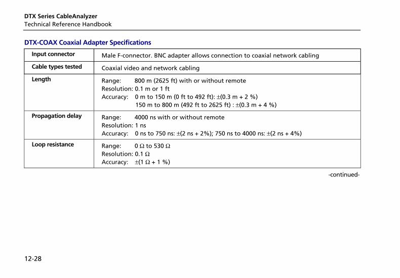
DTX Series CableAnalyzer Technical Reference Handbook
12-28
DTX-COAX Coaxial Adapter Specifications
Input connector Male F-connector. BNC adapter allows connection to coaxial network cabling
Cable types tested Coaxial video and network cabling
Length Range: 800 m (2625 ft) with or without remote Resolution: 0.1 m or 1 ft Accuracy: 0 m to 150 m (0 ft to 492 ft): ±(0.3 m + 2 %) 150 m to 800 m (492 ft to 2625 ft) : ±(0.3 m + 4 %)
Propagation delay Range: 4000 ns with or without remote Resolution: 1 ns Accuracy: 0 ns to 750 ns: ±(2 ns + 2%); 750 ns to 4000 ns: ±(2 ns + 4%)
Loop resistance Range: 0 Ω to 530 Ω Resolution: 0.1 Ω Accuracy: ±(1 Ω + 1 %)
-continued-
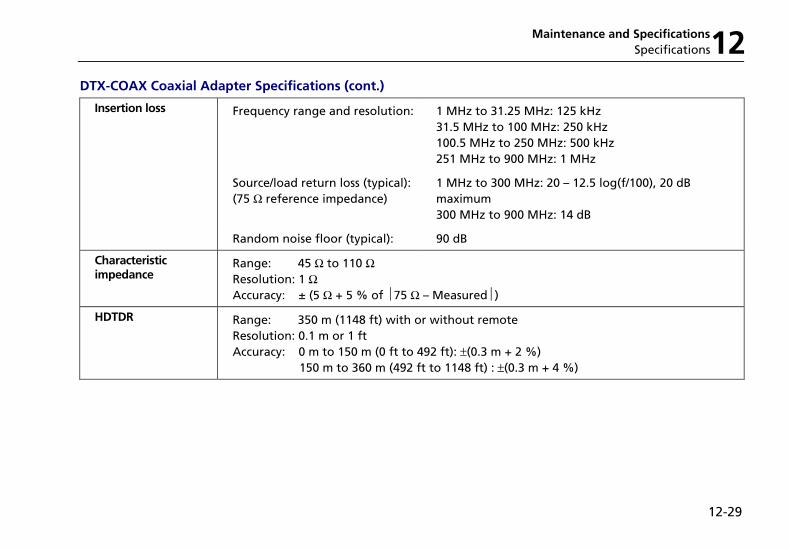
Maintenance and Specifications Specifications12
12-29
DTX-COAX Coaxial Adapter Specifications (cont.)
Insertion loss Frequency range and resolution:
1 MHz to 31.25 MHz: 125 kHz 31.5 MHz to 100 MHz: 250 kHz 100.5 MHz to 250 MHz: 500 kHz 251 MHz to 900 MHz: 1 MHz
Source/load return loss (typical):(75 Ω reference impedance)
1 MHz to 300 MHz: 20 – 12.5 log(f/100), 20 dB maximum 300 MHz to 900 MHz: 14 dB
Random noise floor (typical): 90 dB
Characteristic impedance
Range: 45 Ω to 110 Ω Resolution: 1 Ω Accuracy: ± (5 Ω + 5 % of 75 Ω – Measured )
HDTDR Range: 350 m (1148 ft) with or without remote Resolution: 0.1 m or 1 ft Accuracy: 0 m to 150 m (0 ft to 492 ft): ±(0.3 m + 2 %) 150 m to 360 m (492 ft to 1148 ft) : ±(0.3 m + 4 %)
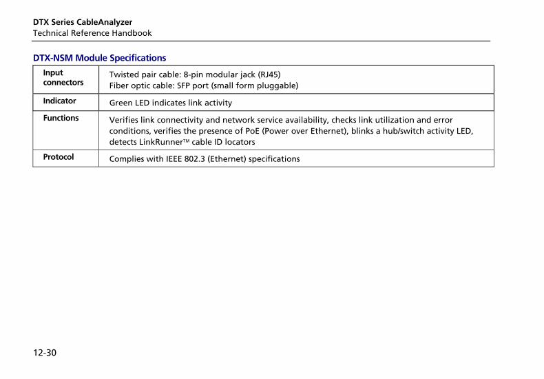
DTX Series CableAnalyzer Technical Reference Handbook
12-30
DTX-NSM Module Specifications
Input connectors
Twisted pair cable: 8-pin modular jack (RJ45) Fiber optic cable: SFP port (small form pluggable)
Indicator Green LED indicates link activity
Functions Verifies link connectivity and network service availability, checks link utilization and error conditions, verifies the presence of PoE (Power over Ethernet), blinks a hub/switch activity LED, detects LinkRunner cable ID locators
Protocol Complies with IEEE 802.3 (Ethernet) specifications
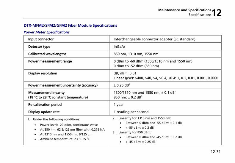
Maintenance and Specifications Specifications12
12-31
DTX-MFM2/SFM2/GFM2 Fiber Module Specifications
Power Meter Specifications
Input connector Interchangeable connector adapter (SC standard)
Detector type InGaAs
Calibrated wavelengths 850 nm, 1310 nm, 1550 nm
Power measurement range 0 dBm to -60 dBm (1300/1310 nm and 1550 nm) 0 dBm to -52 dBm (850 nm)
Display resolution dB, dBm: 0.01 Linear (µW): >400, >40, >4, >0.4, ≤ 0.4: 1, 0.1, 0.01, 0.001, 0.0001
Power measurement uncertainty (accuracy) ± 0.25 dB1
Measurement linearity (18 °C to 28 °C constant temperature)
1300/1310 nm and 1550 nm: ± 0.1 dB2 850 nm: ± 0.2 dB3
Re-calibration period 1 year
Display update rate 1 reading per second
1. Under the following conditions:
• Power level: -20 dBm, continuous wave
• At 850 nm: 62.5/125 µm fiber with 0.275 NA
• At 1310 nm and 1550 nm: 9/125 µm
• Ambient temperature: 23 oC ±5 oC
2. Linearity for 1310 nm and 1550 nm:
• Between 0 dBm and -55 dBm: ± 0.1 dB
• < -55 dBm: ± 0.2 dB
3. Linearity for 850 dBm:
• Between 0 dBm and -45 dBm: ± 0.2 dB
• < -45 dBm: ± 0.25 dB
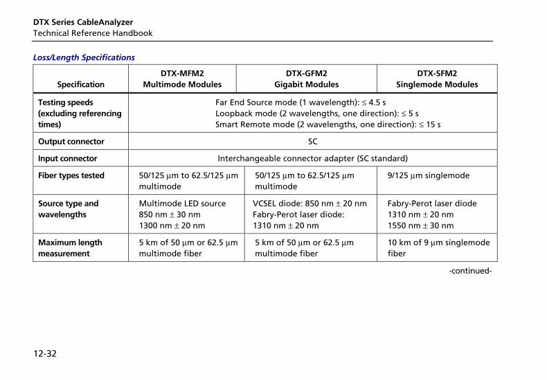
DTX Series CableAnalyzer Technical Reference Handbook
12-32
Loss/Length Specifications
Specification
DTX-MFM2 Multimode Modules
DTX-GFM2 Gigabit Modules
DTX-SFM2 Singlemode Modules
Testing speeds (excluding referencing times)
Far End Source mode (1 wavelength): ≤ 4.5 s Loopback mode (2 wavelengths, one direction): ≤ 5 s Smart Remote mode (2 wavelengths, one direction): ≤ 15 s
Output connector SC
Input connector Interchangeable connector adapter (SC standard)
Fiber types tested 50/125 µm to 62.5/125 µm multimode
50/125 µm to 62.5/125 µm multimode
9/125 µm singlemode
Source type and wavelengths
Multimode LED source 850 nm ± 30 nm 1300 nm ± 20 nm
VCSEL diode: 850 nm ± 20 nm Fabry-Perot laser diode: 1310 nm ± 20 nm
Fabry-Perot laser diode 1310 nm ± 20 nm 1550 nm ± 30 nm
Maximum length measurement
5 km of 50 µm or 62.5 µm multimode fiber
5 km of 50 µm or 62.5 µm multimode fiber
10 km of 9 µm singlemode fiber
-continued-
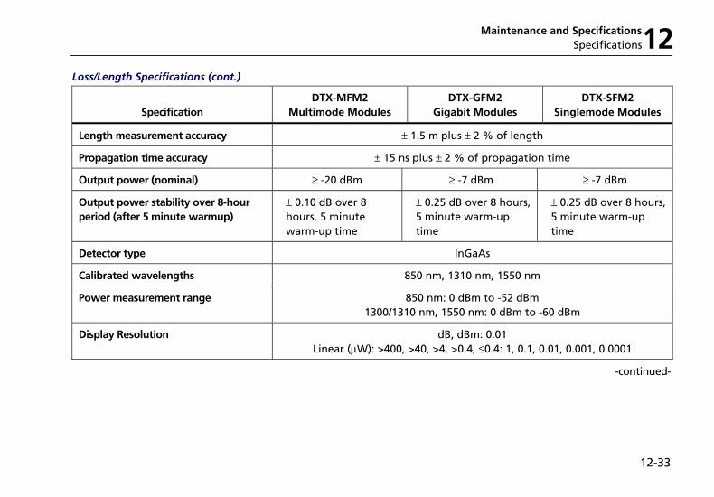
Maintenance and Specifications Specifications12
12-33
Loss/Length Specifications (cont.)
Specification
DTX-MFM2 Multimode Modules
DTX-GFM2 Gigabit Modules
DTX-SFM2 Singlemode Modules
Length measurement accuracy ± 1.5 m plus ± 2 % of length
Propagation time accuracy ± 15 ns plus ± 2 % of propagation time
Output power (nominal) ≥ -20 dBm ≥ -7 dBm ≥ -7 dBm
Output power stability over 8-hour period (after 5 minute warmup)
± 0.10 dB over 8 hours, 5 minute warm-up time
± 0.25 dB over 8 hours, 5 minute warm-up time
± 0.25 dB over 8 hours, 5 minute warm-up time
Detector type InGaAs
Calibrated wavelengths 850 nm, 1310 nm, 1550 nm
Power measurement range 850 nm: 0 dBm to -52 dBm 1300/1310 nm, 1550 nm: 0 dBm to -60 dBm
Display Resolution dB, dBm: 0.01 Linear (µW): >400, >40, >4, >0.4, ≤ 0.4: 1, 0.1, 0.01, 0.001, 0.0001
-continued-
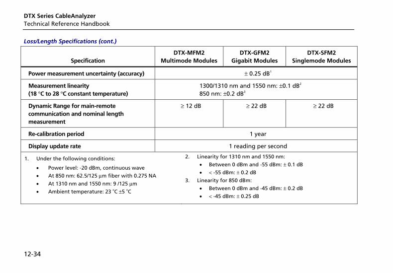
DTX Series CableAnalyzer Technical Reference Handbook
12-34
Loss/Length Specifications (cont.)
Specification
DTX-MFM2 Multimode Modules
DTX-GFM2 Gigabit Modules
DTX-SFM2 Singlemode Modules
Power measurement uncertainty (accuracy) ± 0.25 dB1
Measurement linearity (18 °C to 28 °C constant temperature)
1300/1310 nm and 1550 nm: ±0.1 dB2 850 nm: ±0.2 dB3
Dynamic Range for main-remote communication and nominal length measurement
≥ 12 dB ≥ 22 dB ≥ 22 dB
Re-calibration period 1 year
Display update rate 1 reading per second
1. Under the following conditions:
• Power level: -20 dBm, continuous wave
• At 850 nm: 62.5/125 µm fiber with 0.275 NA
• At 1310 nm and 1550 nm: 9 /125 µm
• Ambient temperature: 23 oC ±5 oC
2. Linearity for 1310 nm and 1550 nm:
• Between 0 dBm and -55 dBm: ± 0.1 dB
• < -55 dBm: ± 0.2 dB
3. Linearity for 850 dBm:
• Between 0 dBm and -45 dBm: ± 0.2 dB
• < -45 dBm: ± 0.25 dB
Maintenance and Specifications Specifications12
12-35
Visual Fault Locator
Output power* 316 µw (-5 dBm) ≤ peak power ≥ 1.0 mw (0 dbm)
Operating wavelength 650 nm nominal
Spectral width (RMS) ± 3 nm
Output modes Continuous wave and pulsed mode (2 Hz to 3 Hz blink frequency)
Connector adapter 2.5 mm universal
Laser safety Class II CDRH
* Into SMF-28 singlemode fiber, continuous wave and pulse modes, SC/UPC connector.
Tone Generator
Generates tones that can be detected by a tone probe, such as a Fluke Networks IntelliTone probe. The tones are generated on all pairs.
Frequency range of tones: 440 Hz to 831 Hz

DTX Series CableAnalyzer Technical Reference Handbook
12-36
Power
Notes
You do not need to fully discharge the battery before recharging it.
The battery will not charge at temperatures outside of 0 °C to 45 °C (32 °F to 113 °F). The battery charges at a reduced rate between 40 °C and 45 °C (104 °F and 113 °F).
• Main unit and remote: Lithium-ion battery pack, 7.4 V, 4000 mAh
• Typical battery life: 10 to 12 hours
• Charge time (with tester off): 4 hours (below 40 °C)
• AC adapter/charger, USA version: Linear power supply; 108 V ac to 132 V ac input; 15 V dc, 1.2 A output
• AC adapter/charger, international version: Switching power supply; 90 V ac to 264 V ac input; 15 V dc; 1.2 A output
• Memory backup power in main unit: Lithium battery
• Typical life of lithium battery: 5 years
Electromagnetic Compatibility
Emissions: EN 61326-1, Class A
Immunity: EN 61326-1
Input Ratings
A DTX Series tester and remote are designed to measure unpowered cables. The inputs are protected against continuous, current-limited telco voltages (<100 mA) and can withstand occasional overvoltages of less than 30 V rms (42 V peak, 60 V dc).
Certification and Compliance
; N10140
Conforms to relevant Australian standards
P Conforms to relevant European Union directives.
) Listed by the Canadian Standards Association.
Maintenance and Specifications Specifications12
12-37
CSA Standards
CAN/CSA-C22.2 No. 1010.1-92 + Amendment 2: 1997 and CAN/CSA-C22.2 No. 1010.1 2000 (2nd edition) Safety Requirements for Electrical Equipment for Measurement, Control, and Laboratory Use, Part 1: General Requirements.
Safety
CAN/CSA-C22.2 No. 1010.1-92 + Amendment 2: 1997; Overvoltage Category II, Pollution degree 2, 30 V.
EN61010, 2nd Edition, MEASUREMENT (Installation) CATEGORY I, Pollution Degree 2 per IEC1010-1 refers to the level of Impulse Withstand Voltage protection provided. Equipment of MEASUREMENT CATEGORY I is for measurements performed on circuits not directly connected to mains.
Laser Classification and Safety for DTX-MFM2, DTX-GFM2, and DTX-SFM2 Fiber Modules
OUTPUT port: Class 1
VFL port: Class 2
Complies with EN60825-1 and EN61010-1 (CE) and CFR21
Memory for Test Results
Internal memory stores up to 250 Cat 6 Autotest results, including graphical data.
The 16 MB memory card included stores up to 500 Cat 6 Autotest results, including graphical data.
1 MB Flash EPROM allows software and test limit updates.
LinkWare software lets you upload Autotest results to a PC from the tester or a memory card reader.
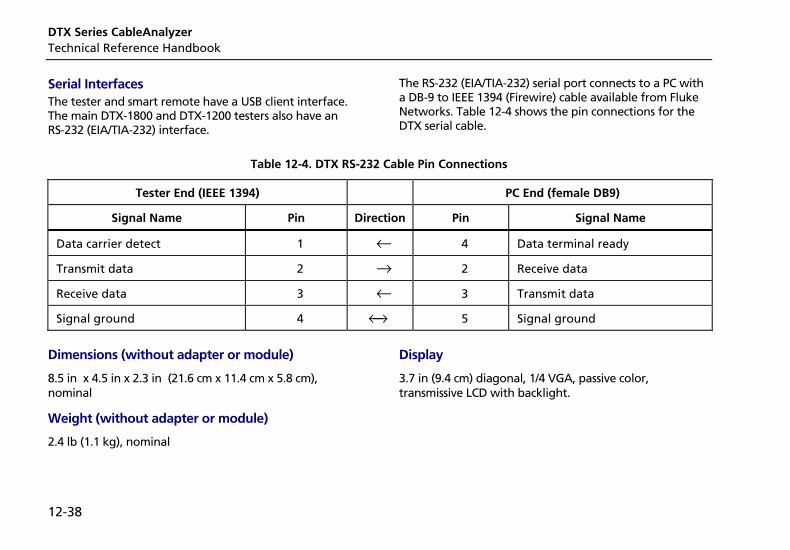
DTX Series CableAnalyzer Technical Reference Handbook
12-38
Serial Interfaces The tester and smart remote have a USB client interface. The main DTX-1800 and DTX-1200 testers also have an RS-232 (EIA/TIA-232) interface.
The RS-232 (EIA/TIA-232) serial port connects to a PC with a DB-9 to IEEE 1394 (Firewire) cable available from Fluke Networks. Table 12-4 shows the pin connections for the DTX serial cable.
Table 12-4. DTX RS-232 Cable Pin Connections
Tester End (IEEE 1394) PC End (female DB9)
Signal Name Pin Direction Pin Signal Name
Data carrier detect 1 ← 4 Data terminal ready
Transmit data 2 → 2 Receive data
Receive data 3 ← 3 Transmit data
Signal ground 4 ←→ 5 Signal ground
Dimensions (without adapter or module)
8.5 in x 4.5 in x 2.3 in (21.6 cm x 11.4 cm x 5.8 cm), nominal
Weight (without adapter or module)
2.4 lb (1.1 kg), nominal
Display
3.7 in (9.4 cm) diagonal, 1/4 VGA, passive color, transmissive LCD with backlight.
Appendices
Appendix Title Page
A Fiber Test Method Reference Tables....................................................................................A-1 B Loss Test Methods for Fiber Cabling ....................................................................................B-1

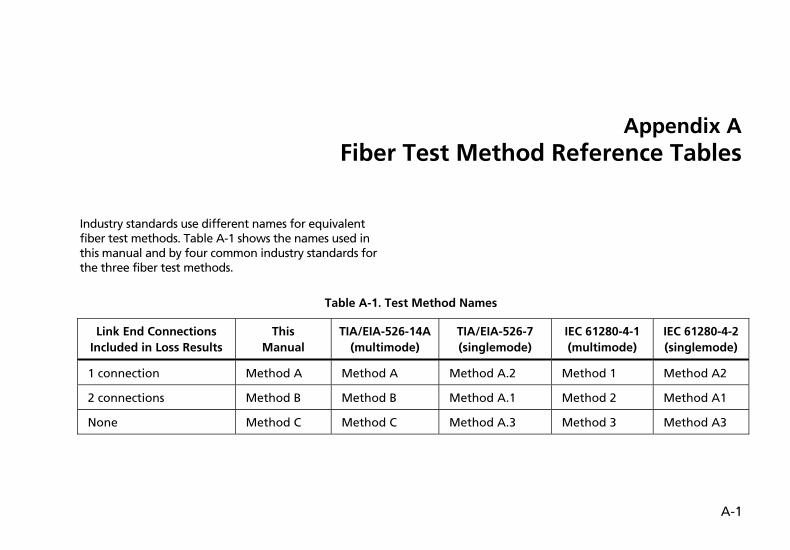
A-1
Appendix A Fiber Test Method Reference Tables
Industry standards use different names for equivalent fiber test methods. Table A-1 shows the names used in this manual and by four common industry standards for the three fiber test methods.
Table A-1. Test Method Names
Link End Connections Included in Loss Results
This Manual
TIA/EIA-526-14A(multimode)
TIA/EIA-526-7 (singlemode)
IEC 61280-4-1 (multimode)
IEC 61280-4-2(singlemode)
1 connection Method A Method A Method A.2 Method 1 Method A2
2 connections Method B Method B Method A.1 Method 2 Method A1
None Method C Method C Method A.3 Method 3 Method A3
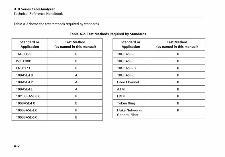
DTX Series CableAnalyzer Technical Reference Handbook
A-2
Table A-2 shows the test methods required by standards.
Table A-2. Test Methods Required by Standards
Standard or Application
Test Method (as named in this manual)
TIA-568-B B
ISO 11801 B
EN50173 B
10BASE-FB A
10BASE-FP A
10BASE-FL A
10/100BASE-SX B
100BASE-FX B
1000BASE-LX B
1000BASE-SX B
Standard or Application
Test Method (as named in this manual)
10GBASE-S B
10GBASE-L B
10GBASE-LX B
10GBASE-E B
Fibre Channel B
ATMl B
FDDI B
Token Ring B
Fluke Networks General Fiber
B
B-1
Appendix B Loss Test Methods for Fiber Cabling
Introduction
Note
The following discussion uses TIA/EIA-526 terminology for the names of the three common test methods. See Appendix A for a cross-reference of the method names in various standards.
The number of fiber connections represented in loss test results depends on the method used for making reference and test connections. This appendix describes the three common methods, A, B, and C, which are defined in the ANSI/TIA/EIA-526-14A multimode standard, and their equivalents, A.2, A.1, and A.3, which are defined in the ANSI/TIA/EIA-526-7 singlemode standard.
This appendix also describes modified and alternate connections you can use for all types of connectors, including installations that have different connector styles at the patch panels and outlets.
Use the Test Method setting on the tester’s Fiber menu in SETUP to record the method used. This setting does not affect loss results. It is only saved with the results to record which method you used.
Note
ANSI/TIA/EIA-526-14A and 526-7 specify Method B for measuring loss on multimode premises fiber and Method A.1 for singlemode premises fiber, respectively.
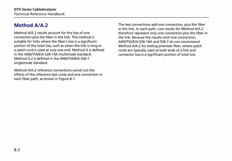
DTX Series CableAnalyzer Technical Reference Handbook
B-2
Method A/A.2 Method A/A.2 results account for the loss of one connection plus the fiber in the link. This method is suitable for links where the fiber's loss is a significant portion of the total loss, such as when the link is long or a patch cord is used at only one end. Method A is defined in the ANSI/TIA/EIA-526-14A multimode standard. Method A.2 is defined in the ANSI/TIA/EIA-526-7 singlemode standard.
Method A/A.2 reference connections cancel out the effects of the reference test cords and one connection in each fiber path, as shown in Figure B-1.
The test connections add one connection, plus the fiber in the link, to each path. Loss results for Method A/A.2 therefore represent only one connection plus the fiber in the link. Because the results omit one connection, ANSI/TIA/EIA-526-14A and 526-7 do not recommend Method A/A.2 for testing premises fiber, where patch cords are typically used at both ends of a link and connector loss is a significant portion of total loss.
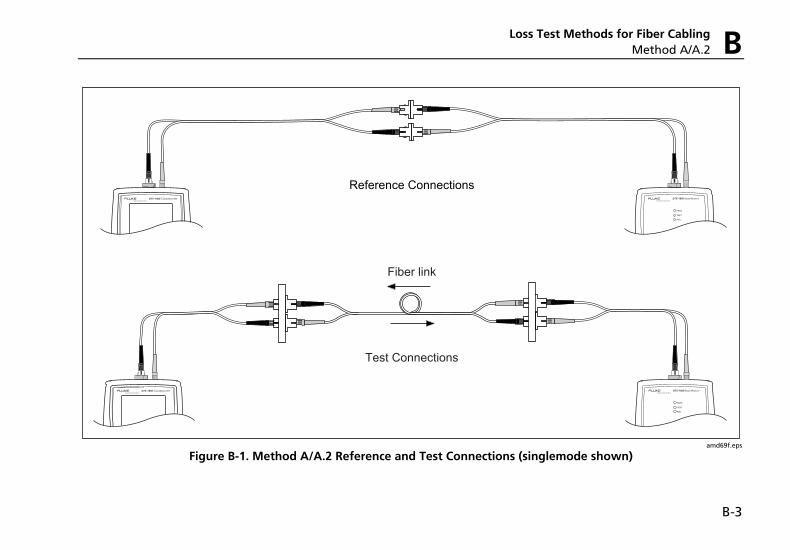
Loss Test Methods for Fiber Cabling Method A/A.2 B
B-3
amd69f.eps
Figure B-1. Method A/A.2 Reference and Test Connections (singlemode shown)
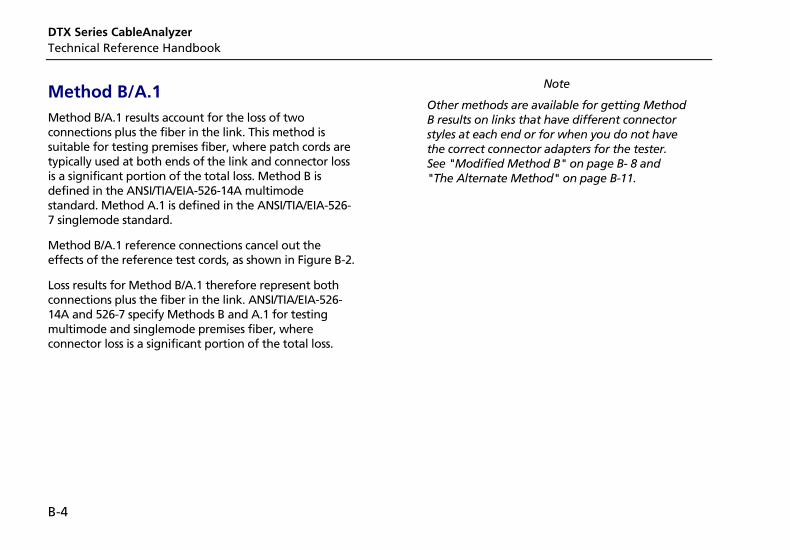
DTX Series CableAnalyzer Technical Reference Handbook
B-4
Method B/A.1 Method B/A.1 results account for the loss of two connections plus the fiber in the link. This method is suitable for testing premises fiber, where patch cords are typically used at both ends of the link and connector loss is a significant portion of the total loss. Method B is defined in the ANSI/TIA/EIA-526-14A multimode standard. Method A.1 is defined in the ANSI/TIA/EIA-526-7 singlemode standard.
Method B/A.1 reference connections cancel out the effects of the reference test cords, as shown in Figure B-2.
Loss results for Method B/A.1 therefore represent both connections plus the fiber in the link. ANSI/TIA/EIA-526-14A and 526-7 specify Methods B and A.1 for testing multimode and singlemode premises fiber, where connector loss is a significant portion of the total loss.
Note
Other methods are available for getting Method B results on links that have different connector styles at each end or for when you do not have the correct connector adapters for the tester. See "Modified Method B" on page B- 8 and "The Alternate Method" on page B-11.
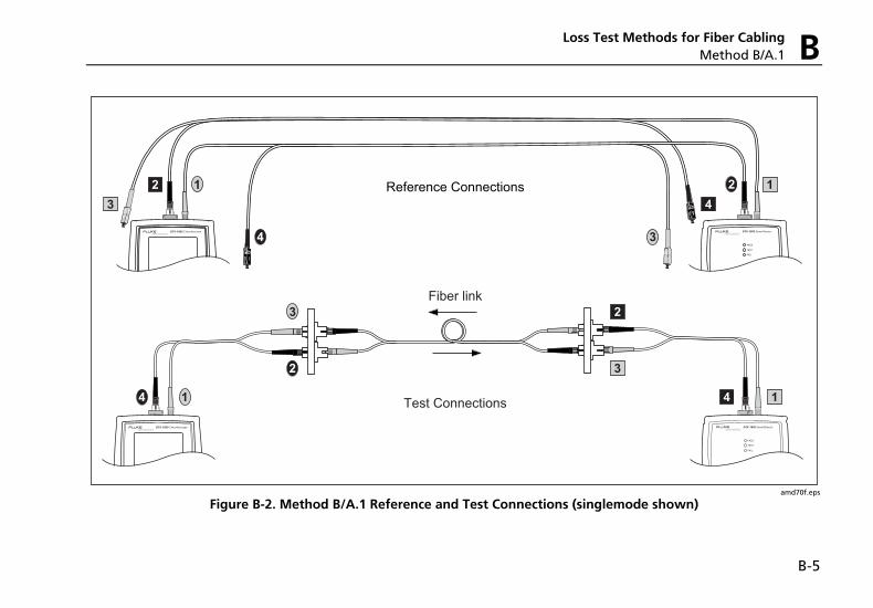
Loss Test Methods for Fiber Cabling Method B/A.1 B
B-5
amd70f.eps
Figure B-2. Method B/A.1 Reference and Test Connections (singlemode shown)
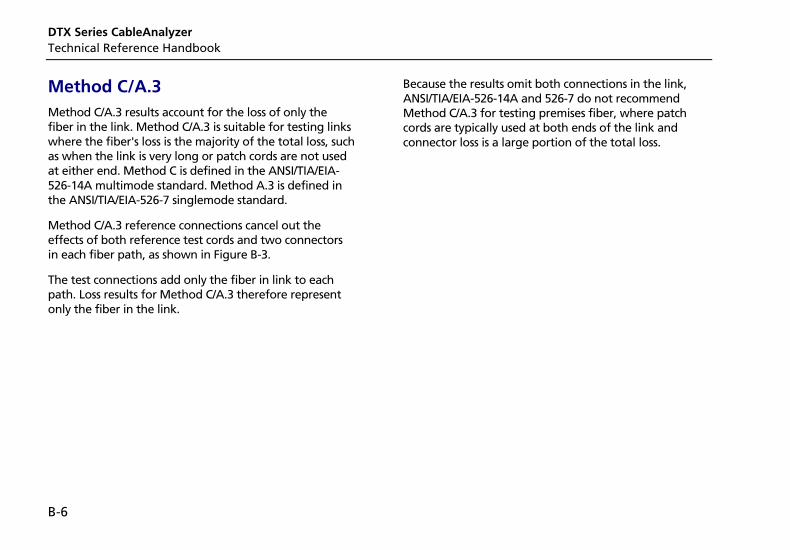
DTX Series CableAnalyzer Technical Reference Handbook
B-6
Method C/A.3 Method C/A.3 results account for the loss of only the fiber in the link. Method C/A.3 is suitable for testing links where the fiber's loss is the majority of the total loss, such as when the link is very long or patch cords are not used at either end. Method C is defined in the ANSI/TIA/EIA-526-14A multimode standard. Method A.3 is defined in the ANSI/TIA/EIA-526-7 singlemode standard.
Method C/A.3 reference connections cancel out the effects of both reference test cords and two connectors in each fiber path, as shown in Figure B-3.
The test connections add only the fiber in link to each path. Loss results for Method C/A.3 therefore represent only the fiber in the link.
Because the results omit both connections in the link, ANSI/TIA/EIA-526-14A and 526-7 do not recommend Method C/A.3 for testing premises fiber, where patch cords are typically used at both ends of the link and connector loss is a large portion of the total loss.
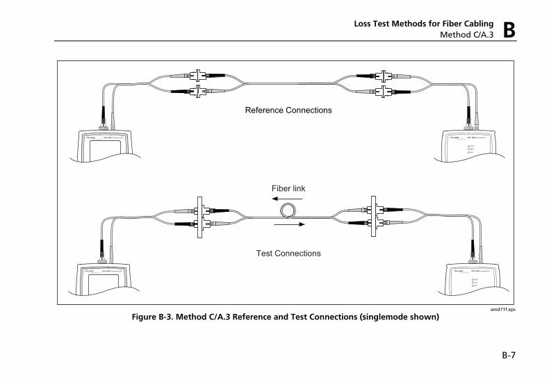
Loss Test Methods for Fiber Cabling Method C/A.3 B
B-7
amd71f.eps
Figure B-3. Method C/A.3 Reference and Test Connections (singlemode shown)
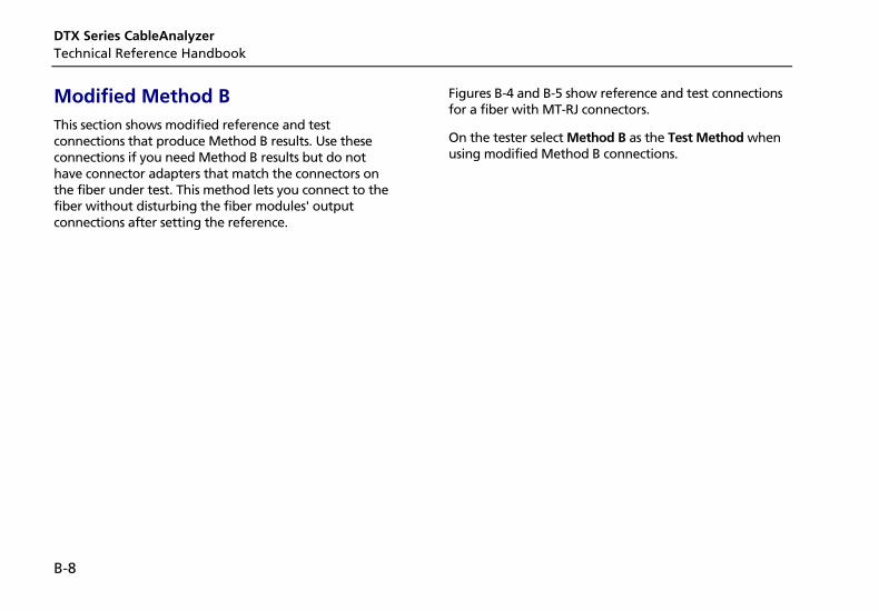
DTX Series CableAnalyzer Technical Reference Handbook
B-8
Modified Method B This section shows modified reference and test connections that produce Method B results. Use these connections if you need Method B results but do not have connector adapters that match the connectors on the fiber under test. This method lets you connect to the fiber without disturbing the fiber modules' output connections after setting the reference.
Figures B-4 and B-5 show reference and test connections for a fiber with MT-RJ connectors.
On the tester select Method B as the Test Method when using modified Method B connections.
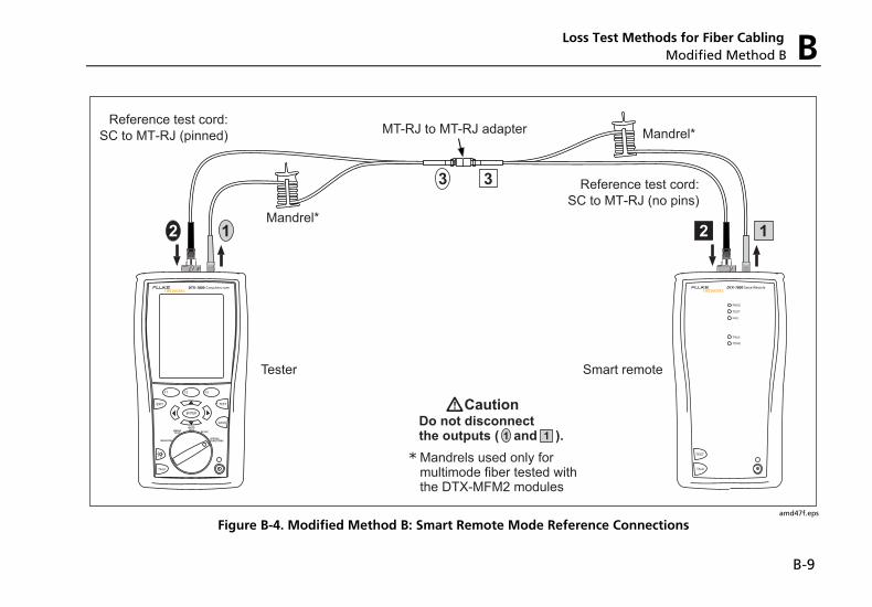
B-9
122 1
3
Do not disconnectthe outputs ( and ). 1 1
WCaution
3
Reference test cord:SC to MT-RJ (pinned)
Reference test cord:SC to MT-RJ (no pins)
* Mandrels used only for multimode fiber tested with the DTX-MFM2 modules
MT-RJ to MT-RJ adapter
Mandrel*
Mandrel*
Tester Smart remote
amd47f.eps
Figure B-4. Modified Method B: Smart Remote Mode Reference Connections
Loss Test Methods for Fiber Cabling Modified Method B B
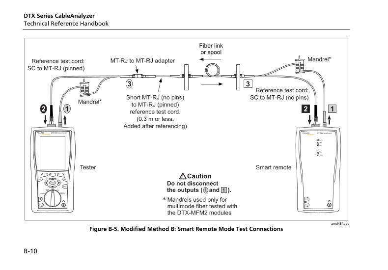
DTX Series CableAnalyzer Technical Reference Handbook
B-10
Fiber linkor spool
33
Short MT-RJ (no pins)to MT-RJ (pinned)
reference test cord.(0.3 m or less.
Added after referencing)
Do not disconnectthe outputs ( and ). 1 1
WCaution
Reference test cord:SC to MT-RJ (pinned)
Reference test cord:SC to MT-RJ (no pins)
* Mandrels used only for multimode fiber tested with the DTX-MFM2 modules
MT-RJ to MT-RJ adapter
Mandrel*
Mandrel*
Tester Smart remote
122 1
TALK
MONITOR
ENTER
TEST
SAVE
SPECIALFUNCTIONS
SETUP
AUTOTESTSINGLE
TEST
EXIT
F1 F2 F3
TALK
amd48f.eps
Figure B-5. Modified Method B: Smart Remote Mode Test Connections
Loss Test Methods for Fiber Cabling The Alternate Method B
B-11
The Alternate Method Like Method B/A.1, the alternate method produces results that account for the loss of two connections plus the fiber in the link.
An advantage of this method is that you can test links that have different connector styles at each end.
Figure B-6 shows reference and test connections for the alternate method. The link under test has MT-RJ connectors at one end, and LC connectors at the other end.
Using an SC to MT-RJ patch cord and an SC to LC patch cord for reference and test connections may seem like an easier way to connect to the link; however, that would require an MT-RJ to LC patch cord for reference connections. The reference and test connections would be the Method C/A.3 configuration, as shown in Figure B-3. The loss results would account for the loss of only the fiber in the link.
To account for the loss of both connections in the link, you must add connections to each end after referencing, as shown at the bottom of Figure B-6. Each fiber path then has four connections. Since two connections were canceled out during referencing, the test results include the loss of the two connections at the ends of the link.
You may also use the alternate method to test links that have the same connector style at both ends. As with modified Method B, this method lets you test links when you do not have the correct connector adapters for the tester. For referencing, use the connections shown at the top of Figure B-6. For testing, add the appropriate short patch cords at each end. Figure B-7 shows an example of these test connections for a link with MT-RJ connectors at both ends.
On the tester select Method B as the Test Method when using these alternate connections.

B-12
amd114f.eps
Figure B-6. Alternate Method Reference and Test Connections for a Hybrid Link (singlemode shown)
DTX Series CableAnalyzer Technical Reference Handbook
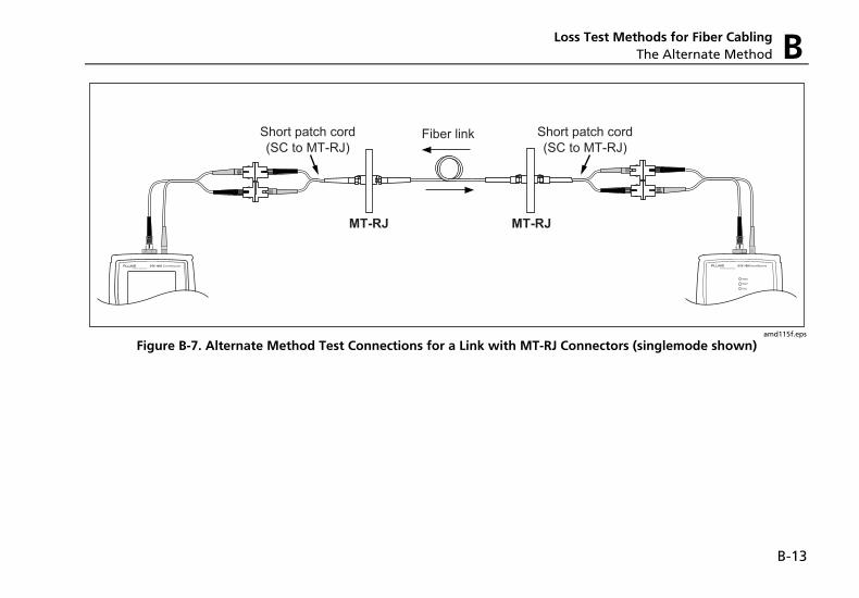
Loss Test Methods for Fiber Cabling The Alternate Method B
B-13
amd115f.eps
Figure B-7. Alternate Method Test Connections for a Link with MT-RJ Connectors (singlemode shown)

DTX Series CableAnalyzer Technical Reference Handbook
B-14
1
Index
—$— $
cable IDs, 1-29
—*— * in results, 3-12 * in test settings, 10-2, 10-3, 10-4,
10-5, 10-6
—3— 3 dB rule, 3-24
—4— 4 dB rule, 3-20
—6— 606-A, 2-24
—A— accessories
optional, 12-11 standard, 1-3
ACR test, 3-22 adapters, 1-18 asterisk in results, 3-12 attenuation. See insertion loss Audible Tone, 1-26 Auto Increment
overview, 1-29 tutorial, 2-20
Auto Sequence
overview, 1-29 tutorial, 2-21
Autotest asterisk in results, 3-12 automatic diagnostics, 3-11 coaxial, 4-6 coaxial results, 4-9 copper cabling failures, 5-2 Far End Source mode, 6-34 fiber cabling failures, 8-2 Loopback mode, 6-26 main screen, 1-23 results
coaxial, 4-9 Far End Source mode, 6-40 Loopback mode, 6-32 Smart Remote mode, 6-24 twisted pair, 3-9
Smart Remote mode, 6-19
DTX Series CableAnalyzer Technical Reference Handbook
2
twisted pair, 3-6
—B— backbone template, 2-24 backlight
key, 1-9 timer, 1-25
Bad patch cord, 5-3 battery
charging, 1-14 clock battery, 12-7 replacement, 12-7 retraining the battery gauge, 12-6 status, 1-16 storage, 12-8
beeper, 1-26 Bi-Directional
setting, 6-14 testing, 6-42
Broadcasts, 9-13 buttons, 1-9
—C— Cable ID Source, 1-28 cable IDs, 1-28
$, 1-29
auto increment, 2-20 downloaded from a PC, 1-29 sequential, 2-21 templates, 2-24 troubleshooting, 2-23
Cable Type coaxial, 4-3 custom, 10-1 fiber types tested, 12-32 new cable types database, 12-5 twisted pair, 3-3 twisted pair types tested, 12-16
calibration, 12-2 campus template, 2-25 cautions, 1-6, 6-3, 12-1 certifications, 12-36 channel test connections, 3-8 characteristic impedance
coaxial, 4-10 diagnosing failures, 5-7 specifications, 12-27 twisted pair, 3-15
checkmark coaxial results, 4-9 fiber results, 6-25, 6-33, 6-41 twisted pair results, 3-10
cleaning display and case, 12-6
fiber connectors, 12-7 cleaning connectors and adapters,
6-8 coaxial
Autotest, 4-6 reference, 4-1 results, 4-9 test settings, 4-3
Collisions, 9-13 Company, 2-2 compliance, 12-36 connections
channel, 3-8 fiber. See Smart Remote,
Loopback, or Far End Source mode
for fiber test methods, B-1 permanent link, 3-7
connector adapter cleaning, 6-9 installation, 6-6
Connector Type, 6-15 connectors
fiber module, 6-5 main tester, 1-11 optical connector maintenance,
12-7 RJ11 (telephone), 1-7
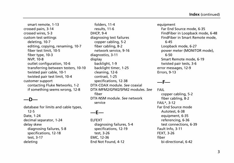
Index (continued)
3
smart remote, 1-13 crossed pairs, 3-14 crossed wires, 5-3 custom test settings
deleting, 10-7 editing, copying, renaming, 10-7 fiber test limit, 10-5 fiber type, 10-3 NVP, 10-8 outlet configuration, 10-6 transferring between testers, 10-10 twisted pair cable, 10-1 twisted pair test limit, 10-4
customer support contacting Fluke Networks, 1-2 if something seems wrong, 12-8
—D— database for limits and cable types,
12-5 Date, 1-24 decimal separator, 1-24 delay skew
diagnosing failures, 5-8 specifications, 12-18 test, 3-17
deleting
folders, 11-4 results, 11-6
DHCP, 9-4 diagnosing test failures
copper cabling, 5-2 fiber cabling, 8-2 network service, 9-16
diagnostics, 3-11 display
backlight, 1-9 backlight timer, 1-25 cleaning, 12-6 contrast, 1-25 specifications, 12-38
DTX-COAX module. See coaxial DTX-MFM2/GFM2/SFM2 modules. See
fiber DTX-NSM module. See network
service
—E— ELFEXT
diagnosing failures, 5-4 specifications, 12-19 test, 3-26
EMC, 12-36 End Not Found, 4-12
equipment Far End Source mode, 6-35 FindFiber in Loopback mode, 6-48 FindFiber in Smart Remote mode,
6-45 Loopback mode, 6-27 power meter (MONITOR mode),
6-50 Smart Remote mode, 6-19 twisted pair tests, 3-6
error messages, 12-9 Errors, 9-13
—F— FAIL
copper cabling, 5-2 fiber cabling, 8-2
FAIL*, 3-12 Far End Source mode
Autotest, 6-38 equipment, 6-35 referencing, 6-36 test connections, 6-39
Fault Info, 3-11 FEXT, 3-26 fiber
bi-directional, 6-42
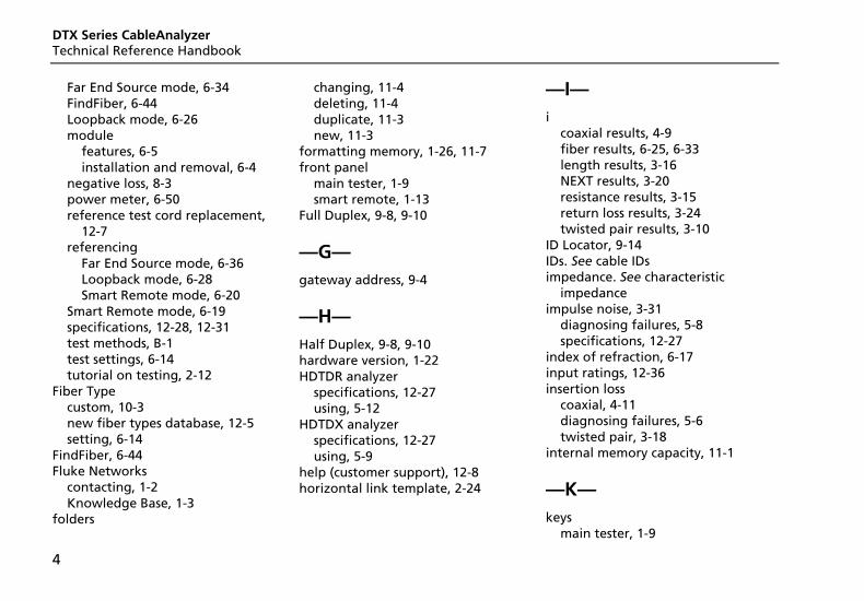
DTX Series CableAnalyzer Technical Reference Handbook
4
Far End Source mode, 6-34 FindFiber, 6-44 Loopback mode, 6-26 module
features, 6-5 installation and removal, 6-4
negative loss, 8-3 power meter, 6-50 reference test cord replacement,
12-7 referencing
Far End Source mode, 6-36 Loopback mode, 6-28 Smart Remote mode, 6-20
Smart Remote mode, 6-19 specifications, 12-28, 12-31 test methods, B-1 test settings, 6-14 tutorial on testing, 2-12
Fiber Type custom, 10-3 new fiber types database, 12-5 setting, 6-14
FindFiber, 6-44 Fluke Networks
contacting, 1-2 Knowledge Base, 1-3
folders
changing, 11-4 deleting, 11-4 duplicate, 11-3 new, 11-3
formatting memory, 1-26, 11-7 front panel
main tester, 1-9 smart remote, 1-13
Full Duplex, 9-8, 9-10
—G— gateway address, 9-4
—H— Half Duplex, 9-8, 9-10 hardware version, 1-22 HDTDR analyzer
specifications, 12-27 using, 5-12
HDTDX analyzer specifications, 12-27 using, 5-9
help (customer support), 12-8 horizontal link template, 2-24
—I— i
coaxial results, 4-9 fiber results, 6-25, 6-33 length results, 3-16 NEXT results, 3-20 resistance results, 3-15 return loss results, 3-24 twisted pair results, 3-10
ID Locator, 9-14 IDs. See cable IDs impedance. See characteristic
impedance impulse noise, 3-31
diagnosing failures, 5-8 specifications, 12-27
index of refraction, 6-17 input ratings, 12-36 insertion loss
coaxial, 4-11 diagnosing failures, 5-6 twisted pair, 3-18
internal memory capacity, 11-1
—K— keys
main tester, 1-9
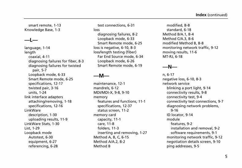
Index (continued)
5
smart remote, 1-13 Knowledge Base, 1-3
—L— language, 1-14 length
coaxial, 4-11 diagnosing failures for fiber, 8-3 diagnosing failures for twisted
pair, 5-7 Loopback mode, 6-33 Smart Remote mode, 6-25 specifications, 12-17 twisted pair, 3-16 units, 1-24
link interface adapters attaching/removing, 1-18 specifications, 12-16
LinkWare description, 1-30 uploading results, 11-9
LinkWare Stats, 1-30 List, 1-29 Loopback mode
Autotest, 6-30 equipment, 6-27 referencing, 6-28
test connections, 6-31 loss
diagnosing failures, 8-2 Loopback mode, 6-33 Smart Remote mode, 6-25
loss is negative, 6-10, 8-3 loss/length testing (fiber)
Far End Source mode, 6-34 Loopback mode, 6-26 Smart Remote mode, 6-19
—M— maintenance, 12-1 mandrels, 6-12 MDI/MDI-X, 9-8, 9-10 memory
features and functions, 11-1 specifications, 12-37 status screen, 11-2
memory card capacity, 11-1 care, 11-8 folders, 11-3 inserting and removing, 1-27
Method A, B, C, 6-15 Method A/A.2, B-2 Method B
modified, B-8 standard, 6-18
Method B/A.1, B-4 Method C/A.3, B-6 modified Method B, B-8 monitoring network traffic, 9-12 moving results, 11-6 MT-RJ, 6-18
—N— n, 6-17 negative loss, 6-10, 8-3 network service
blinking a port light, 9-14 connectivity results, 9-8 connectivity test, 9-4 connectivity test connections, 9-7 diagnosing network problems,
9-16 ID locator, 9-14 module
features, 9-2 installation and removal, 9-2 software requirements, 9-1
monitoring network traffic, 9-12 negotiation details screen, 9-10 ping addresses, 9-5
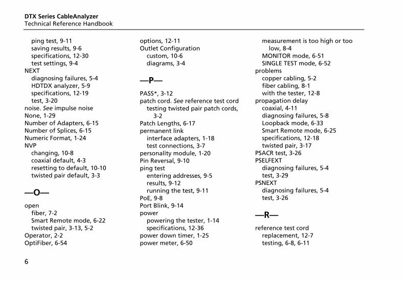
DTX Series CableAnalyzer Technical Reference Handbook
6
ping test, 9-11 saving results, 9-6 specifications, 12-30 test settings, 9-4
NEXT diagnosing failures, 5-4 HDTDX analyzer, 5-9 specifications, 12-19 test, 3-20
noise. See impulse noise None, 1-29 Number of Adapters, 6-15 Number of Splices, 6-15 Numeric Format, 1-24 NVP
changing, 10-8 coaxial default, 4-3 resetting to default, 10-10 twisted pair default, 3-3
—O— open
fiber, 7-2 Smart Remote mode, 6-22 twisted pair, 3-13, 5-2
Operator, 2-2 OptiFiber, 6-54
options, 12-11 Outlet Configuration
custom, 10-6 diagrams, 3-4
—P— PASS*, 3-12 patch cord. See reference test cord
testing twisted pair patch cords, 3-2
Patch Lengths, 6-17 permanent link
interface adapters, 1-18 test connections, 3-7
personality module, 1-20 Pin Reversal, 9-10 ping test
entering addresses, 9-5 results, 9-12 running the test, 9-11
PoE, 9-8 Port Blink, 9-14 power
powering the tester, 1-14 specifications, 12-36
power down timer, 1-25 power meter, 6-50
measurement is too high or too low, 8-4
MONITOR mode, 6-51 SINGLE TEST mode, 6-52
problems copper cabling, 5-2 fiber cabling, 8-1 with the tester, 12-8
propagation delay coaxial, 4-11 diagnosing failures, 5-8 Loopback mode, 6-33 Smart Remote mode, 6-25 specifications, 12-18 twisted pair, 3-17
PSACR test, 3-26 PSELFEXT
diagnosing failures, 5-4 test, 3-29
PSNEXT diagnosing failures, 5-4 test, 3-26
—R— reference test cord
replacement, 12-7 testing, 6-8, 6-11
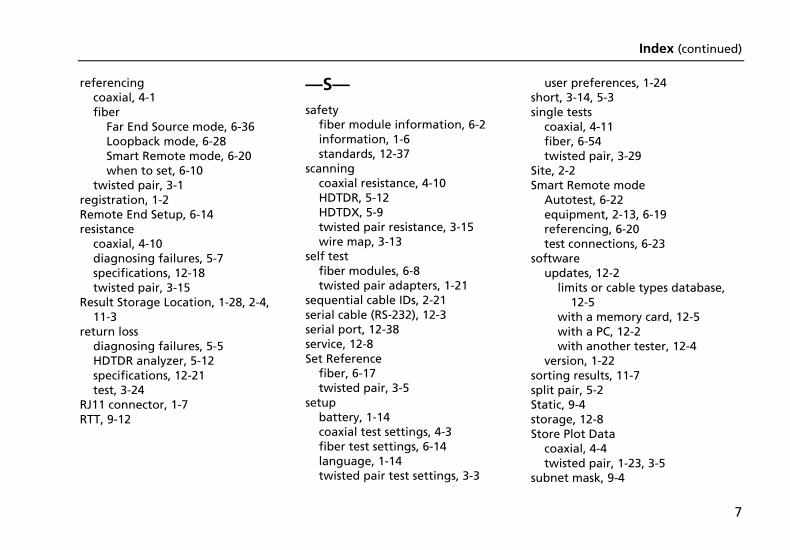
Index (continued)
7
referencing coaxial, 4-1 fiber
Far End Source mode, 6-36 Loopback mode, 6-28 Smart Remote mode, 6-20 when to set, 6-10
twisted pair, 3-1 registration, 1-2 Remote End Setup, 6-14 resistance
coaxial, 4-10 diagnosing failures, 5-7 specifications, 12-18 twisted pair, 3-15
Result Storage Location, 1-28, 2-4, 11-3
return loss diagnosing failures, 5-5 HDTDR analyzer, 5-12 specifications, 12-21 test, 3-24
RJ11 connector, 1-7 RTT, 9-12
—S— safety
fiber module information, 6-2 information, 1-6 standards, 12-37
scanning coaxial resistance, 4-10 HDTDR, 5-12 HDTDX, 5-9 twisted pair resistance, 3-15 wire map, 3-13
self test fiber modules, 6-8 twisted pair adapters, 1-21
sequential cable IDs, 2-21 serial cable (RS-232), 12-3 serial port, 12-38 service, 12-8 Set Reference
fiber, 6-17 twisted pair, 3-5
setup battery, 1-14 coaxial test settings, 4-3 fiber test settings, 6-14 language, 1-14 twisted pair test settings, 3-3
user preferences, 1-24 short, 3-14, 5-3 single tests
coaxial, 4-11 fiber, 6-54 twisted pair, 3-29
Site, 2-2 Smart Remote mode
Autotest, 6-22 equipment, 2-13, 6-19 referencing, 6-20 test connections, 6-23
software updates, 12-2
limits or cable types database, 12-5
with a memory card, 12-5 with a PC, 12-2 with another tester, 12-4
version, 1-22 sorting results, 11-7 split pair, 5-2 Static, 9-4 storage, 12-8 Store Plot Data
coaxial, 4-4 twisted pair, 1-23, 3-5
subnet mask, 9-4
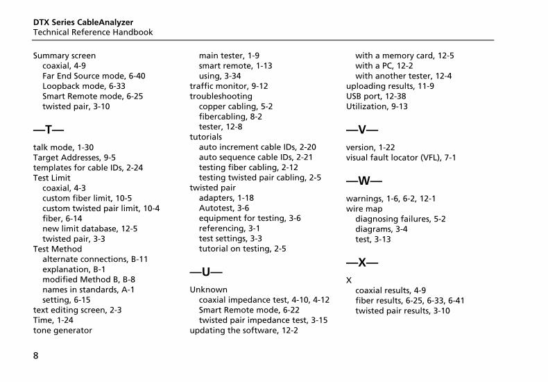
DTX Series CableAnalyzer Technical Reference Handbook
8
Summary screen coaxial, 4-9 Far End Source mode, 6-40 Loopback mode, 6-33 Smart Remote mode, 6-25 twisted pair, 3-10
—T— talk mode, 1-30 Target Addresses, 9-5 templates for cable IDs, 2-24 Test Limit
coaxial, 4-3 custom fiber limit, 10-5 custom twisted pair limit, 10-4 fiber, 6-14 new limit database, 12-5 twisted pair, 3-3
Test Method alternate connections, B-11 explanation, B-1 modified Method B, B-8 names in standards, A-1 setting, 6-15
text editing screen, 2-3 Time, 1-24 tone generator
main tester, 1-9 smart remote, 1-13 using, 3-34
traffic monitor, 9-12 troubleshooting
copper cabling, 5-2 fibercabling, 8-2 tester, 12-8
tutorials auto increment cable IDs, 2-20 auto sequence cable IDs, 2-21 testing fiber cabling, 2-12 testing twisted pair cabling, 2-5
twisted pair adapters, 1-18 Autotest, 3-6 equipment for testing, 3-6 referencing, 3-1 test settings, 3-3 tutorial on testing, 2-5
—U— Unknown
coaxial impedance test, 4-10, 4-12 Smart Remote mode, 6-22 twisted pair impedance test, 3-15
updating the software, 12-2
with a memory card, 12-5 with a PC, 12-2 with another tester, 12-4
uploading results, 11-9 USB port, 12-38 Utilization, 9-13
—V— version, 1-22 visual fault locator (VFL), 7-1
—W— warnings, 1-6, 6-2, 12-1 wire map
diagnosing failures, 5-2 diagrams, 3-4 test, 3-13
—X— X
coaxial results, 4-9 fiber results, 6-25, 6-33, 6-41 twisted pair results, 3-10