droplet breakup mechanisms
DESCRIPTION
DropletTRANSCRIPT
Droplet breakup mechanisms: Stepwise equilibrium versus transient dispersion
J. M. H. Janssen and H. E. H. Meijer
Centre for Polymers and Composites, Eindhoven University of Technology,
P.O. Box 513, 5600 MB Eindhoven, The Netherlands
(Received 13 October 1992; accepted 27 February 1993)
Synopsis
In dispersive mixing of immiscible liquids the minimum attainable dropsize is often deduced from the critical value of the Capillary number (the ratio of the shear stress to the interfacial stress) necessary for drop breakup under quasiequilibrium conditions. The critical Capillary number shows a minimum if the viscosity ratio between dispersed and continuous phase is about one. Hence, it is commonly accepted that the finest morphology is obtained if both viscosities match. In practical mixing devices, however, small drops are formed by a transient mechanism of thread breakup during extension rather than by stepwise breakup under equilibrium conditions. For Newtonian liquids, a comparison is made between the dropsizes resulting from a stepwise equilibrium and a transient breakup mechanism. Generally, the transient mechanism yields smaller drops and, more interestingly, a higher viscosity ratio between the dispersed and continuous phases results in a finer morphology, as already indicated by Tjahjadi and Ottino ( 1991). In the present paper the comparison is elaborated over a broad range of the relevant parameters while a compact illustrative presentation of the results is given to stress the possible consequences for practical blend morphologies.
INTRODUCTION
Many industrial processes involve dispersion of immiscible liquid/liquid systems; the final morphology resulting from the mixing process influences the mechanical and other properties of the product. An elementary step in the mixing process is the deformation and breakup of a single dispersed drop in the flow field of a second immiscible liquid. Drop deformation is promoted by the deforming shear stress r imposed by the flow and counteracted by the interfacial stress a/R (with (T the interfacial tension and R the drop radius) minimizing the inter-facial area, thus tending to a spherical drop shape. The ratio between the competitive stresses is expressed by the Capillary number
with vc the viscosity of the continuous phase and p the shear rate [ = \I(2D:D), D being the rate of deformation tensor]. If the Capillary number is small, the interfacial stress dominates and a steady ellipsoid drop shape exists. Upon excess of a critical value, Cacrit, no equilibrium shape exists and the drop becomes unstable and finally breaks. It should be noticed that the critical Capillary number considers drop breakup
0 1993 by The Society of Rheology, Inc. J. Rheol. 37(4), July/August 1993 014%6055/93/37(4)/597/12/$4.00 597
598
IO’
100
JANSSEN AND MEIJER
IO-' [ J IO-6 IO-5 10-d 10” 10-Z 10-I 100 10’ 102 103
P
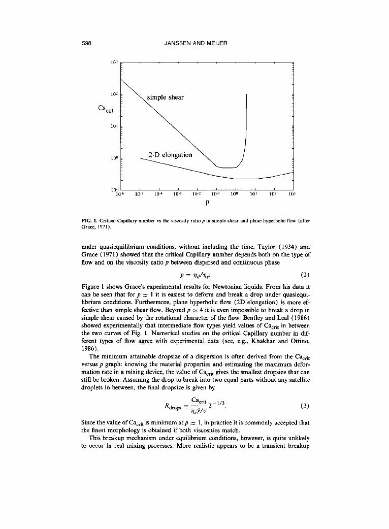
FIG. 1. Critical Capillary number vs the viscosity ratio p in simple shear and plane hyperbolic flow (after Grace, 1971).
under quasiequilibrium conditions, without including the time. Taylor (1934) and Grace ( 1971) showed that the critical Capillary number depends both on the type of flow and on the viscosity ratio p between dispersed and continuous phase
Figure 1 shows Grace’s experimental results for Newtonian liquids. From his data it can be seen that for p z 1 it is easiest to deform and break a drop under quasiequi- librium conditions. Furthermore, plane hyperbolic flow (2D elongation) is more ef- fective than simple shear flow. Beyond p u 4 it is even impossible to break a drop in simple shear caused by the rotational character of the flow. Bentley and Lea1 ( 1986) showed experimentally that intermediate flow types yield values of Ca,nt in between the two curves of Fig. 1. Numerical studies on the critical Capillary number in dif- ferent types of flow agree with experimental data (see, e.g., Khakhar and Ottino, 1986).
The minimum attainable dropsize of a dispersion is often derived from the Cactii, versus p graph: knowing the material properties and estimating the maximum defor- mation rate in a mixing device, the value of C!%+ gives the smallest dropsize that can still be broken. Assuming the drop to break into two equal parts without any satellite droplets in between, the final dropsize is given by
Since the value of C!a,it is minimum at p z 1, in practice it is commonly accepted that the finest morphology is obtained if both viscosities match.
This breakup mechanism under equilibrium conditions, however, is quite unlikely to occur in real mixing processes. More realistic appears to be a transient breakup
TRANSIENT DROPLET BREAKUP 599
0 I 0 o&o 1
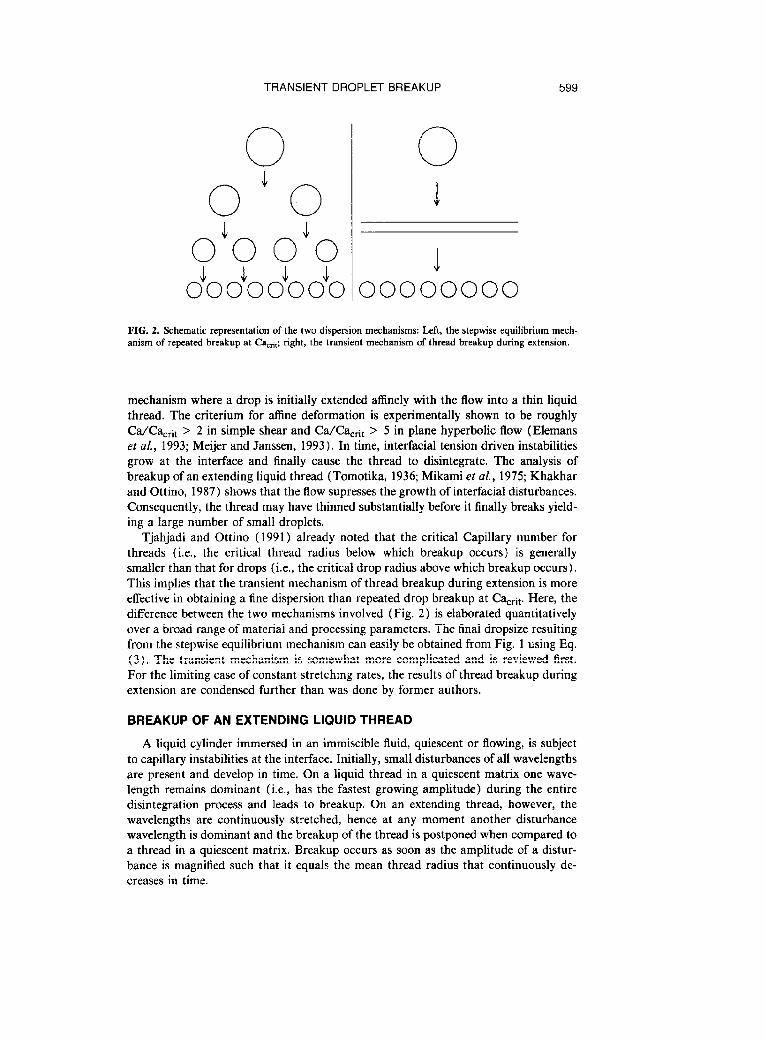
o&o o&o 1 4 J J 4 0000000000000000 FIG. 2. Schematic representation of the two dispersion mechanisms: Left, the stepwise equilibrium mech- anism of repeated breakup at Cacri,; right, the transient mechanism of thread breakup during extension.
mechanism where a drop is initially extended affinely with the flow into a thin liquid thread. The criterium for affine deformation is experimentally shown to be roughly Ca/Ca,a > 2 in simple shear and Ca/Ca,..u > 5 in plane hyperbolic flow (Elemans et al., 1993; Meijer and Janssen, 1993 ) , In time, inter-facial tension driven instabilities grow at the interface and finally cause the thread to disintegrate. The analysis of breakup of an extending liquid thread (Tomotika, 1936; Mikami et al., 1975; Khakhar and Ottino, 1987) shows that the flow supresses the growth of interfacial disturbances. Consequently, the thread may have thinned substantially before it finally breaks yield- ing a large number of small droplets.
Tjahjadi and Ottino ( 1991) already noted that the critical Capillary number for threads (i.e., the critical thread radius below which breakup occurs) is generally smaller than that for drops (i.e., the critical drop radius above which breakup occurs), This implies that the transient mechanism of thread breakup during extension is more effective in obtaining a fine dispersion than repeated drop breakup at Cacrit. Here, the difference between the two mechanisms involved (Fig. 2) is elaborated quantitatively over a broad range of material and processing parameters. The final dropsize resulting from the stepwise equilibrium mechanism can easily be obtained from Fig. 1 using Eq. (3). The transient mechanism is somewhat more complicated and is reviewed first. For the limiting case of constant stretching rates, the results of thread breakup during extension are condensed further than was done by former authors.
BREAKUP OF AN EXTENDING LIQUID THREAD
A liquid cylinder immersed in an immiscible fluid, quiescent or flowing, is subject to capillary instabilities at the interface. Initially, small disturbances of all wavelengths are present and develop in time. On a liquid thread in a quiescent matrix one wave- length remains dominant (i.e., has the fastest growing amplitude) during the entire disintegration process and leads to breakup. On an extending thread, however, the wavelengths are continuously stretched, hence at any moment another disturbance wavelength is dominant and the breakup of the thread is postponed when compared to a thread in a quiescent matrix. Breakup occurs as soon as the amplitude of a distur- bance is magnified such that it equals the mean thread radius that continuously de- creases in time.
600 JANSSEN AND MEIJER
In (R/so)
and
ln(a/ao)
0
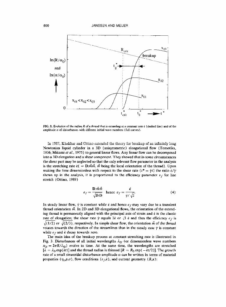
FIG. 3. Evolution of the radius R of a thread that is extending at a constant rate i (dashed line) and of the amplitude n of disturbances with different initial wave numbers (full curves).
In 1987, Khakhar and Ottino extended the theory for breakup of an infinitely long Newtonian liquid cylinder in a 3D (axisymmetric) elongational flow (Tomotika, 1936; Mikami et aL, 1975) to general linear flows. Any linear flow can be decomposed into a 3D elongation and a shear component. They showed that in some circumstances the shear part may be neglected so that the only relevant flow parameter in the analysis is the stretching rate ti( = D:6& $ being the local orientation of the thread). Upon making the time dimensionless with respect to the shear rate (t* = pt) the ratio ir/i, shows up in the analysis, it is proportional to the efficiency parameter Ed for line stretch (Ottino, 1989)
D:C’& ef = JD:D hence ef = -&J. (4)
In steady linear flow, Jo is constant while g and hence ef may vary due to a transient thread orientation A. In 2D and 3D elongational flows, the orientation of the extend- ing thread is permanently aligned with the principal axis of strain and g is the classic rate of elongation; the shear rate i/ equals 2i or J3 i and thus the efficiency ef is
JiEor JEVG, respectively. In simple shear flow, the orientation 6 of the thread rotates towards the direction of the streamlines thus in the steady case p is constant while ef and i decay towards zero.
The main idea of the breakup process at constant stretching rate is illustrated in Fig. 3. Disturbances of all initial wavelengths Lci (or dimensionless wave numbers xci = 2TR/&i) evolve in time. At the same time, the wavelengths are stretched [L = /2c exp(it)] and the thread radius is thinned [R = Rc exp( -&/2)]. The growth rate of a small sinusoidal disturbance amplitude a can be written in terms of material properties ( qC,p,o), flow conditions (efii), and current geometry (RJ) :
TRANSIENT DROPLET BREAKUP 601
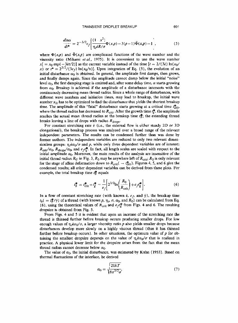
---WV)-3(Pl))Q,(X$)-1 , 1 (5) where @(x,p) and & (x,~) are complicated functions of the wave number and the viscosity ratio (Mikami et aL, 1975). It is convenient to use the wave number x[ = x0 exp( -3.&t/2)] as the current variable instead of the time [t = 2/( 3&) ln(xd x) or t+ = 23’2/(3ef) ln(xo/x)]. Upon integration of Eq. (5), the evolution of an initial disturbance a0 is obtained. In general, the amplitude first damps, then grows, and finally damps again. Since the amplitude cannot damp below the initial “noise” level ao, the first damping stage is omitted and, after some delay time, a starts growing from ag. Breakup is achieved if the amplitude of a disturbance intersects with the continuously decreasing mean thread radius. Since a whole range of disturbances, with different wave numbers and initiation times, may lead to breakup, the initial wave number xoi has to be optimized to find the disturbance that yields the shortest breakup time, The amplitude of this “fatal” disturbance starts growing at a critical time &it, where the thread radius has decreased to Rcct. After the growth time t$, the amplitude reaches the actual mean thread radius at the breakup time tf& the extending thread breaks leaving a line of drops with radius Rdrops.
For constant stretching rate 6 (i.e., the external flow is either steady 2D or 3D elongational), the breakup process was analyzed over a broad range of the relevant independent parameters. The results can be condensed further than was done by former authors. The independent variables are reduced to only two relevant dimen- sionless groups: v&ao/cr and p, while only three dependent variables are of interest: R,dag, Drops/%, and e&. * In fact, all length scales are scaled with respect to the initial amplitude a@ Moreover, the main results of the analysis are insensitive of the initial thread radius Ro: in Fig. 3, Ro may be anywhere left of Rcet; Ro is only relevant for the stage of afline deformation down to Rcet ( -+ tf&). Figures 4, 5, and 6 give the condensed results; all other dependent variables can be derived from these plots. For example, the total breakup time 8 equals
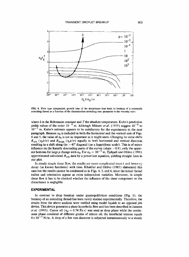
t$ = t,*,t+tg* = -j 23’21n(z) +eft:]. (6)
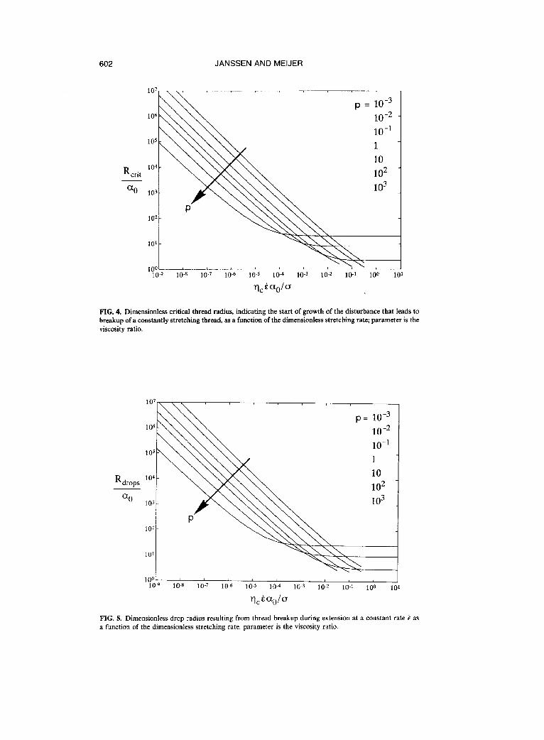
In a flow of constant stretching rate (with known g, ef, and i/), the breakup time tb( = t$/p) of a thread (with known p, vC, u, ag, and Ro) can be calculated from Eq. (6), using the theoretical values of R,ii, and e& from Figs. 4 and 6. The resulting dropsize is obtained from Fig. 5.
From Figs. 4 and 5 it is evident that upon an increase of the stretching rate the thread is thinned further before breakup occurs producing smaller drops. For low enough values of qgada, a larger viscosity ratio p also yields smaller drops because disturbances develop more slowly on a highly viscous thread (thus it has thinned further before breakup occurs). In other situations, the optimum value of p for ob- taining the smallest dropsize depends on the value of vciada that is realized in practice. A physical lower limit for the dropsize arises from the fact that the mean thread radius cannot decrease below ag.
The value of ao, the initial disturbance, was estimated by Kuhn (1953). Based on thermal fluctuations of the interface, he derived
21kT d a0= 3/29 87i- u (7)
602 JANSSEN AND MEIJER
R crit
a0
1 1 ,
FIG. 4. Dimensionless critical thread radius, indicating the start of growth of the disturbance that leads to breakup of a constantly stretching thread, as a function of the dimensionless stretching rate; parameter is the viscosity ratio.
R drops
a0
106 1O-2 p= 10-3
10-l 1 10 102 103
100’ 10-q 10-s 10-7 lo-6 10-S 10-4 10-3 10-Z 10-I 100 1
qcbaOlo
FIG. 5. Dimensionless drop radius resulting from thread breakup during extension at a constant rate k as a function of the dimensionless stretching rate; parameter is the viscosity ratio.
TRANSIENT DROPLET BREAKUP 603
6, I
0’ I 10-q 10-R 10.7 10-e 10-S 10-d 10-3 10-z 10-l 100 10’
q,iao/a
FIG. 6. Flow type independent growth time of the disturbance that leads to breakup of a constantly stretching thread as a function of the dimensionless stretching rate; parameter is the viscosity ratio.
where k is the Boltzmann constant and T the absolute temperature. Kuhn’s prediction yields values of the order lop9 m. Although Mikami et nl. (1975) suggest 10-s to lo-’ m, Kuhn’s estimate appears to be satisfactory for the experiments in the next paragraph. Because a0 is included in both the horizontal and the vertical axis of Figs. 4 and 5, the value of a0 is not as important as it might seem: Changing its value shifts RcAt (Q.&/G) and Rdrops (~$/a) equally in both horizontal and vertical direction resulting in a shift along the - 45” diagonal (on a logarithmic scale). This is of minor influence on the linearly descending parts of the curves (slope -0.9); only the appar- ent bottoms for large p change with (x0. For a0 = 10e9 m, Tjahjadi and Ottino ( 1991) approximated calculated Rc+ data by a power-law equation, yielding straight lines in our plot.
In steady simple shear flow, the results are more complicated since k and hence ef decay (as known functions) with time. Khakhar and Ottino (1987) elaborated this case but the results cannot be condensed as in Figs. 4, 5, and 6, since the initial thread radius and orientation appear as extra independent variables. Moreover, in simple shear flow it has to be checked whether the influence of the shear component on the disturbance is negligible.
EXPERIMENTAL
In contrast to drop breakup under quasiequilibrium conditions (Fig. l), the breakup of an extending thread has been rarely studied experimentally. Therefore, the results from the above analysis were verified using model liquids in an opposed jets device. This device generates a plane hyperbolic flow and has been described in Janssen et al. (1993). Castor oil (qd = 0.74 Pa s) was used as drop phase while the contin- uous phase consisted of different grades of silicon oil; the interfacial tension equals 4 x 10V3 N/m. A drop of a few mm diameter is subjected instantaneously to a steady
604
R drops
[ml
JANSSEN AND MEIJER
Q/o [m -‘I
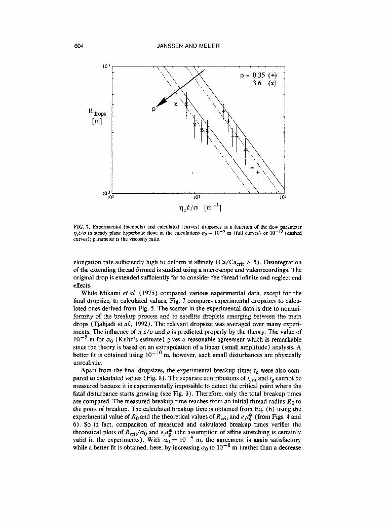
FIG. 7. Experimental (symbols) and calculated (curves) dropsizes as a function of the flow parameter q$/o in steady plane hyperbolic flow; in the calculations q = 10e9 m (full curves) or lo-” (dashed curves); parameter is the viscosity ratio.
elongation rate sufficiently high to deform it affinely (Ca/Ca,ht > 5). Disintegration of the extending thread formed is studied using a microscope and videorecordings. The original drop is extended sufficiently far to consider the thread infinite and neglect end effects.
While Mikami et al. (1975) compared various experimental data, except for the final dropsize, to calculated values, Fig. 7 compares experimental dropsizes to calcu- lated ones derived from Fig. 5. The scatter in the experimental data is due to nonuni- formity of the breakup process and to satellite droplets emerging between the main drops (Tjahjadi et al., 1992). The relevant dropsize was averaged over many experi- ments. The influence of r@/cr and p is predicted properly by the theory. The value of lop9 m for (rc (Kuhn’s estimate) gives a reasonable agreement which is remarkable since the theory is based on an extrapolation of a linear (small amplitude) analysis. A better fit is obtained using 10-l’ m, however, such small disturbances are physically unrealistic.
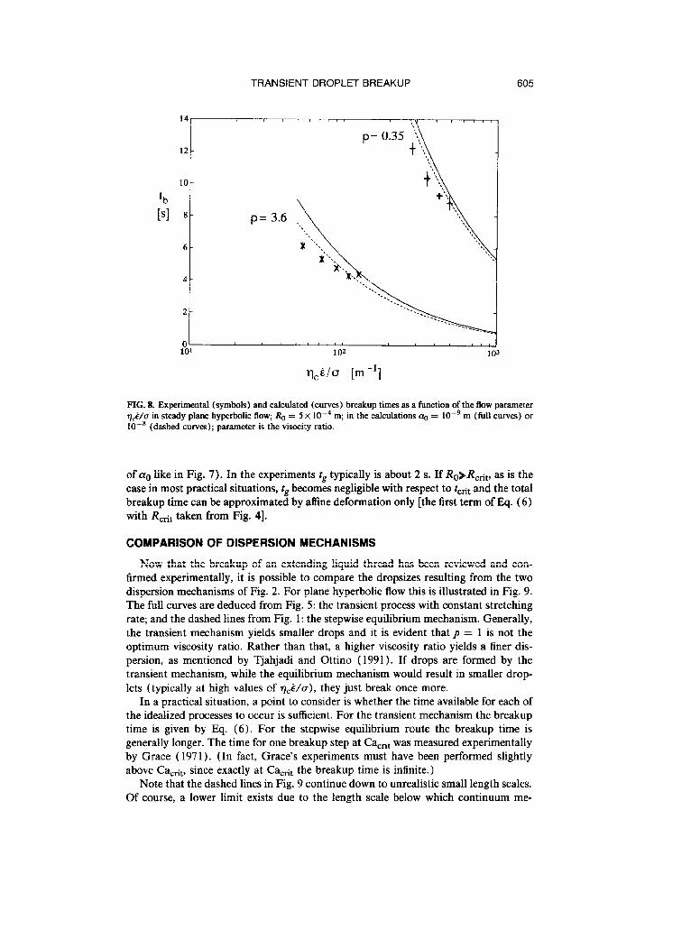
Apart from the final dropsizes, the experimental breakup times tb were also com- pared to calculated values (Fig. 8). The separate contributions of tcet and tg cannot be measured because it is experimentally impossible to detect the critical point where the fatal disturbance starts growing (see Fig. 3). Therefore, only the total breakup times are compared. The measured breakup time reaches from an initial thread radius Ro to the point of breakup. The calculated breakup time is obtained from Eq. (6) using the experimental value of Ro and the theoretical values Of R,-rit and e& (from Figs. 4 and 6). So in fact, comparison of measured and calculated breakup times verifies the theoretical plots of R,+t/ao and e& (the assumption of affine stretching is certainly valid in the experiments). With (x0 = 10e9 m, the agreement is again satisfactory while a better fit is obtained, here, by increasing au to lop8 m (rather than a decrease
TRANSIENT DROPLET BREAKUP 605
1U' 10’ 103
q,tla [m-l]
FIG. 8. Experimental (symbols) and calculated (curves) breakup times as a function of the flow parameter v&//a in steady plane hyperbolic flow; R. = 5 x 10V4 m; in the calculations a~ = IO-’ m (full curves) or lOWE (dashed curves); parameter is the visocity ratio.
of a,-, like in Fig. 7). In the experiments tg typically is about 2 s. If R&R,+ as is the case in most practical situations, tg becomes negligible with respect to tcht and the total breakup time can be approximated by affine deformation only [the first term of Eq. (6) with &tit taken from Fig. 41.
COMPARISON OF DISPERSION MECHANISMS
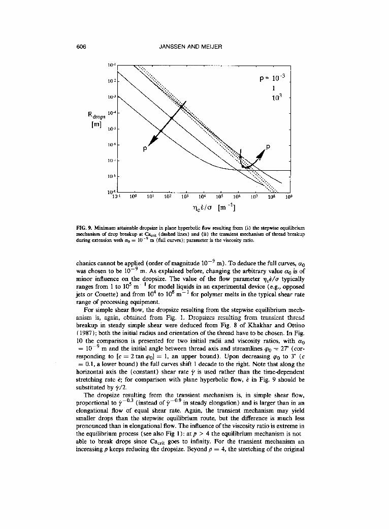
Now that the breakup of an extending liquid thread has been reviewed and con- firmed experimentally, it is possible to compare the dropsizes resulting from the two dispersion mechanisms of Fig. 2. For plane hyperbolic flow this is illustrated in Fig. 9. The full curves are deduced from Fig. 5: the transient process with constant stretching rate; and the dashed lines from Fig. 1: the stepwise equilibrium mechanism. Generally, the transient mechanism yields smaller drops and it is evident that p = 1 is not the optimum viscosity ratio. Rather than that, a higher viscosity ratio yields a finer dis- persion, as mentioned by Tjahjadi and Ottino (1991). If drops are formed by the transient mechanism, while the equilibrium mechanism would result in smaller drop- lets (typically at high values of ~5/a), they just break once more.
In a practical situation, a point to consider is whether the time available for each of the idealized processes to occur is sufficient. For the transient mechanism the breakup time is given by IQ. (6). For the stepwise equilibrium route the breakup time is generally longer. The time for one breakup step at CacAt was measured experimentally by Grace ( 1971). (In fact, Grace’s experiments must have been performed slightly above Cactii,, since exactly at Ca,ht the breakup time is infinite.)
Note that the dashed lines in Fig. 9 continue down to unrealistic small length scales. Of course, a lower limit exists due to the length scale below which continuum me-
606 JANSSEN AND MEIJER
1
R drops
[ml
p= 1o-3
1
10-7 -
10” -
a. ‘.‘\ 10-g . . .,‘. 10-l 100 10’ 102 103 104 105 106 107 10s 1
,
q,b/o [m-l]
FIG. 9. Minimum attainable dropsize in plane hyperbolic flow resulting from (i) the stepwise equilibrium mechanism of drop breakup at C&,+, (dashed lines) and (ii) the transient mechanism of thread breakup during extension with q, = 10e9 m (full curves); parameter is the viscosity ratio.
chanics cannot be applied (order of magnitude 10e9 m). To deduce the full curves, a0 was chosen to be 10m9 m. As explained before, changing the arbitrary value a0 is of minor influence on the dropsize. The value of the flow parameter v&/l/o typically ranges from 1 to lo5 m--I for model liquids in an experimental device (e.g., opposed jets or Couette) and from lo4 to IO8 m-l for polymer melts in the typical shear rate range of processing equipment.
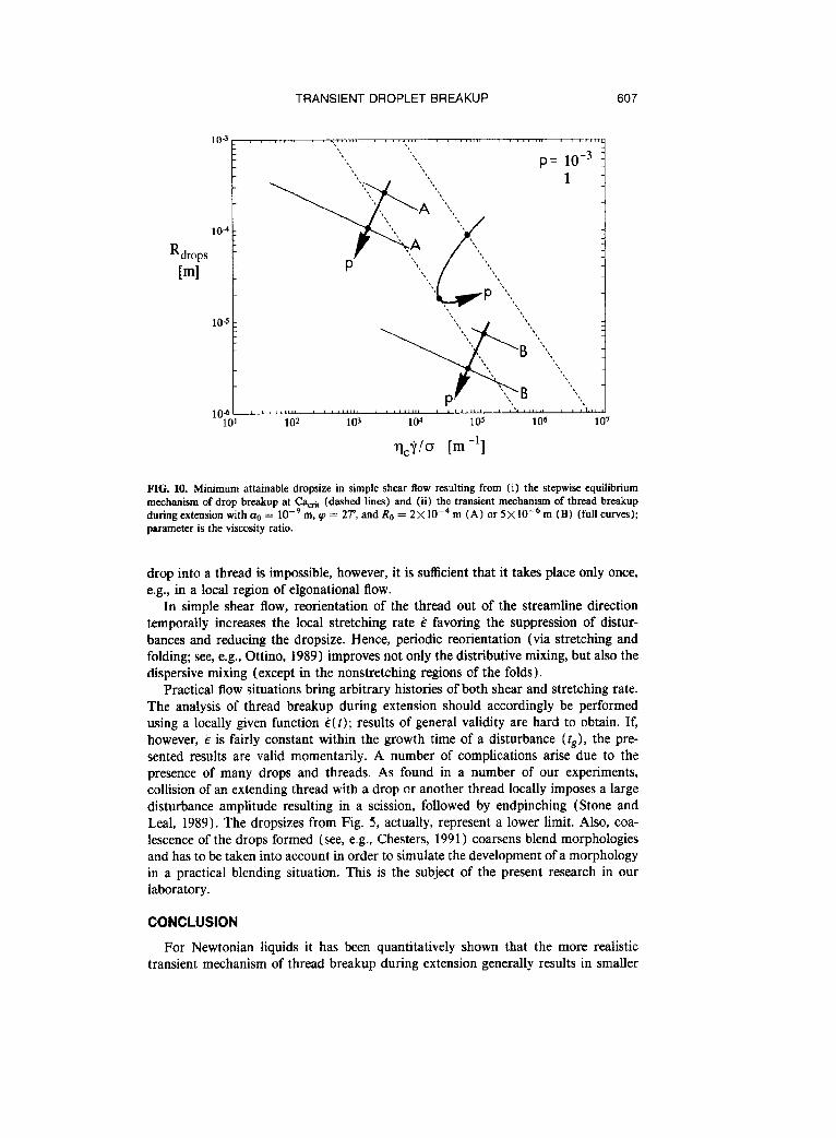
For simple shear flow, the dropsize resulting from the stepwise equilibrium mech- anism is, again, obtained from Fig. 1. Dropsizes resulting from transient thread breakup in steady simple shear were deduced from Fig. 8 of Khakhar and Ottino ( 1987); both the initial radius and orientation of the thread have to be chosen. In Fig. 10 the comparison is presented for two initial radii and viscosity ratios, with a0 = lop9 m and the initial angle between thread axis and streamlines qo = 2P (cor-
responding to [c = 2 tan 901 = 1, an upper bound). Upon decreasing ~0 to 3” (c = 0.1, a lower bound) the full curves shift 1 decade to the right. Note that along the
horizontal axis the (constant) shear rate 9 is used rather than the time-dependent stretching rate .$ for comparison with plane hyperbolic flow, g in Fig. 9 should be substituted by j/2.
The dropsize resulting from the transient mechanism is, in simple shear flow, proportional to i,-o.3 (instead of y-o.9 m steady elongation) and is larger than in an elongational flow of equal shear rate. Again, the transient mechanism may yield smaller drops than the stepwise equilibrium route, but the difference is much less pronounced than in elongational flow. The influence of the viscosity ratio is extreme in the equilibrium process (see also Fig 1) : at p > 4 the equilibrium mechanism is not able to break drops since Cacet goes to infinity. For the transient mechanism an increasing p keeps reducing the dropsize. Beyond p = 4, the stretching of the original
TRANSIENT DROPLET BREAKUP 607
R drops [ml
FIG. 10. Minimum attainable dropsize in simple shear flow resulting from (i) the stepwise equilibrium mechanism of drop breakup at Cacti, (dashed lines) and (ii) the transient mechanism of thread breakup during extension with cro = 10V9 m, q = ZP, and Ro = 2~10~~ m (A) or 5X 10W6 m (B) (full curves); parameter is the viscosity ratio.
drop into a thread is impossible, however, it is sufficient that it takes place only once, e.g., in a local region of elgonational flow.
In simple shear flow, reorientation of the thread out of the streamline direction temporally increases the local stretching rate & favoring the suppression of distur- bances and reducing the dropsize. Hence, periodic reorientation (via stretching and folding; see, e.g., Ottino, 1989) improves not only the distributive mixing, but also the dispersive mixing (except in the nonstretching regions of the folds).
Practical flow situations bring arbitrary histories of both shear and stretching rate. The analysis of thread breakup during extension should accordingly be performed using a locally given function 15(t); results of general validity are hard to obtain. If, however, g is fairly constant within the growth time of a disturbance (f,), the pre- sented results are valid momentarily. A number of complications arise due to the presence of many drops and threads. As found in a number of our experiments, collision of an extending thread with a drop or another thread locally imposes a large disturbance amplitude resulting in a scission, followed by endpinching (Stone and Leal, 1989). The dropsizes from Fig. 5, actually, represent a lower limit. Also, coa- lescence of the drops formed (see, e.g., Chesters, 1991) coarsens blend morphologies and has to be taken into account in order to simulate the development of a morphology in a practical blending situation. This is the subject of the present research in our laboratory.
CONCLUSION
For Newtonian liquids it has been quantitatively shown that the more realistic transient mechanism of thread breakup during extension generally results in smaller
608 JANSSEN AND MEIJER
drops than the stepwise equilibrium mechanism of repeated drop breakup at Ca,,it. The transient mechansim predicts that a viscosity ratio of unity is not optimum for obtaining the finest dispersion. Rather than that, a larger viscosity ratio (thread/ matrix) yields a finer dispersion.
For constant stretching rate, the results of the classic analysis of thread breakup during extension are independent of the initial radius and the initial disturbance am- plitude. Hence, it is possible to condense them in a few graphs. The analysis has been verified experimentally and the agreement is satisfactory.
In fact, the two dispersion mechanisms could already have been compared in the 30’s (Taylor, 1934; Tomotika, 1936). Only the complexity of the transient analysis and the lack of computational facilities, apparently, delayed the complete interpreta- tion of this work.
References
Chesters, A. K. “The modelling of coalescence processes in fluid-liquid dispersions: A review of current understanding,” Trans IChemE 69 259-270 (1991).
Elemans, P. H. M., H. L. Bos, .I. M. H. Janssen, and H. E. H. Meijer, “Transient phenomena in dispersive mixing,” Chem. Eng. Sci. 48, 267-276 (1993).
Grace, H. P., Eng. Found. Res. Conference Mixing 3rd, Andover, N. H. ( 1971), republished as “ Disper- sion phenomena in high viscosity immiscible fluid systems and application of static mixers as dispersion devices in such systems,” Chem. Eng. Commun. 14, 225-277 ( 1982).
Janssen, J. M. H., G. W. M. Peters, and H. E. H. Meijer, “An opposed jets device for studying the breakup of dispersed liquid drops,” Chem. Eng. Sci. 48, 255-265 (1993).
Khakhar, D. V. and J. M. Ottino, “Deformation and breakup of slender drops in linear flows,” J. Fluid Mech. 166, 265-285 (1986).
Khakhar, D. V. and 1. M. Ottino, “Breakup of liquid threads in linear flows,” Int. J. Multiphase Flow 13, 71-86 (1987).
Kuhn, W., “Spontane Aufteilung von Fliissigkeitszylindem in kleine Kugeln,” Kolloid Z. 132, 84-99 (1953).
Meijer, H. E. H. and J. M. H. Janssen, “Mixing of immiscible liquids,” Section 1.4 of Mixing and Compounding-Theory and Practice, Progress in Polymer Proc. Series (Carl Hanser, Munich, 1993).
Mikami, T., R. Cox, and R. G. Mason, “Breakup of extending liquid threads,” Int. J. Multiphase Flow 2, 113-138 (1975).
Ottino, J. M., The Kinematics of Mixing: Stretching, Chaos, and Transport (Cambridge University, Cam- bridge, 1989).
Stone, H. A. and L. G. Leal, “Relaxation and breakup of an initially extended drop in an otherwise quiescent fluid,” J. Fluid Mech. 198, 399427 (1989).
Taylor, G. I., “The formation of emulsions in definable fields of flow,” Proc. R. Sot. London Ser. A 146, 501-523 (1934).
Tjahjadi, M. and J. M. Ottino, “Stretching and breakup of droplets in chaotic flows,” J. Fluid Mech. 232, 191-219 (1991).
Tjahjadi, M., H. A. Stone, and J. M. Ottino, “Satelllite and sub-satellite formation in capillary breakup,” J. Fluid Mech. 243, 297-3 17 ( 1992).
Tomotika, S., “Breaking up of a drop of viscous liquid immersed in another viscous fluid which is extending at a uniform rate,” Proc. R. Sot. London Ser. A 153, 302-318 (1936).