Download - Xenon Detector

Xenon DetectorXenon Detector
Xenon Detector Group
2
ContentsContents
• Cryostat Construction
• Detector Preparation
• Schedule
3
Cryostat ConstructionCryostat Construction
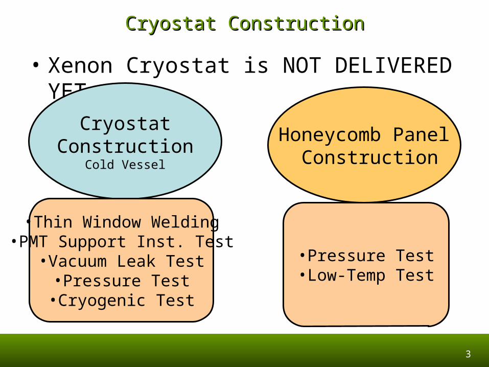
• Xenon Cryostat is NOT DELIVERED YET
CryostatConstruction
Cold Vessel
Honeycomb Panel Construction
•Thin Window Welding•PMT Support Inst. Test
•Vacuum Leak Test•Pressure Test•Cryogenic Test
•Pressure Test•Low-Temp Test
4
Schedule Reported in the Last MeetingSchedule Reported in the Last Meeting• Week 19-23 June:
– Warm vessel: Complete welding of all nozzle (3 days).
– Cold vessel: Complete welding of CF 100 flanges, braze the cooling tube (3 days) Welding test of the windows (2days)
– New foil fabrications (4 days).– Define Honeycomb materials and geometry
(2 days) delivery (15 days)• Week 26-30 June:
– Test box preparation: warm window test box (1day); cold window test box (3days).
– Welding of warm window on the test box (2 days) + helium leak test (1day)+ mechanical test (1day).
– Machining of cold vessel (5 days).• Week 3-7 July:
– Welding of cold window on the test box (2days)- helium lesk test (1day).
– New honeycomb delivered – mechanical test cold window (1day).
– Welding window on cold vessel (2days)• Week 10-14 July:
– Test warm vessel (2days).– Helium test of cold window (1day)– Honeycomb mounting and cold test preparati
on (1day)– Pressure test cold vessel, 4 bar, (1day)
• Week 17-21 July:– Dry out cold vessel (1day)- helium leak test of
metallic sealing on covers (1day).– Mounting of the phototube supporting structur
e (2days)– Welding of the L bracket to hold the arches (p
hototube supporting structure) (1day)– Installation of super insulation and temperatur
e sensors (1day)• Week 24 -28 July:
– Alignment and vessel integration (3days)– Bellows welding (3day)
• Week 31July - 4 Agust:– Helium leak test on the welds (1day)– Internal polishing (3days)– Cleaning and dryout (2days)
• Week 7- 12 August:– Preparation and installation of equipmnets for
the cryocenic test (1day)– Cryogenic test (4days)
• Week 14- 18 August:– Helium leak test of cold vessel (2days)– Prepartation of shipmenet (2days)
• Week 21- 26 August:– Delivery to PSI
End Oct
End Dec
5
Why is Cryostat Construction Delayed?Why is Cryostat Construction Delayed?
• Thin window welding and related tests took longer time than expected, which is now successfully completed.
• PMT support did not fit the cold vessel wall because of deformation that had appeared during construction process.
6
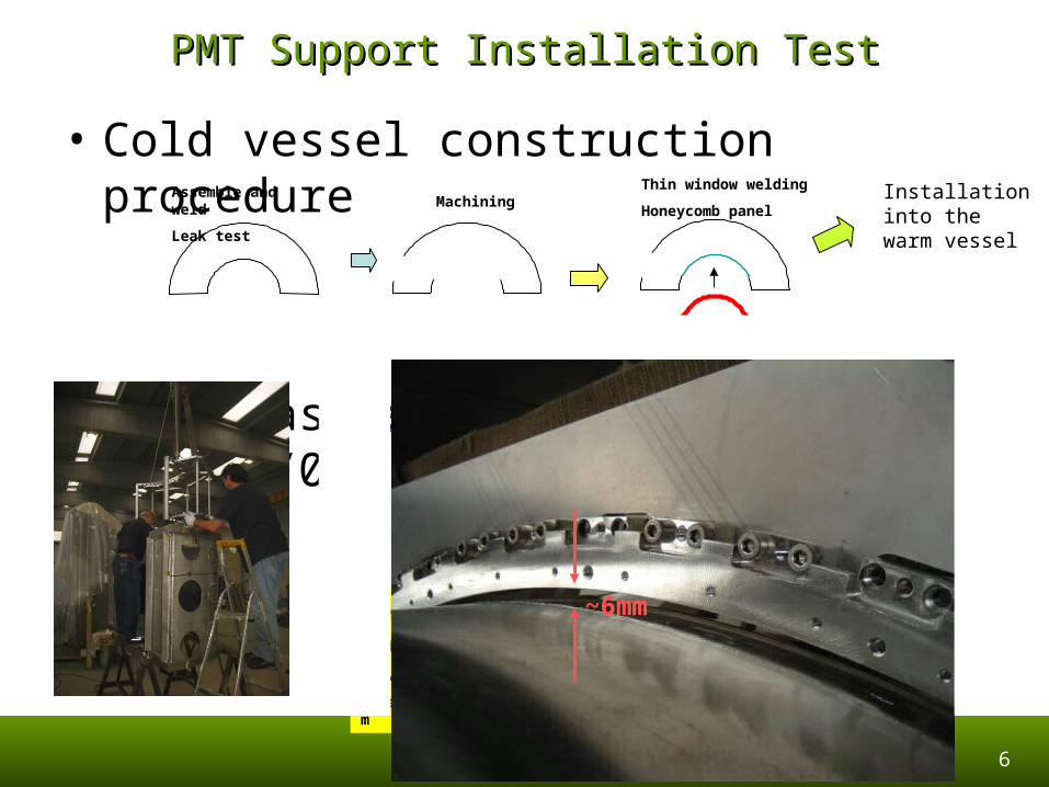
PMT Support Installation TestPMT Support Installation Test
• Cold vessel construction procedure
• Test was performed on 29/Sep/06, but …
Assemble and weld
Leak testMachining
Thin window welding
Honeycomb panelInstallation into the warm vessel
IdealReality
Xenon coming in.•Several mm gap
•LXe R.L. 2.89 cm
Support structure cannot come in
~6mm
7
Protocol UpdateProtocol Update
• Discussion between SIMIC and INFN– Update schedule including remachining of the
cold vessel wall– Check points at milestone activities
• He Leak Test, Pressure Test, etc.
– Assign another SIMIC engineer who can respect the schedule in a cautious manner
– In case of schedule slippage without any acceptable reason, we will stop SIMIC and continue at a different manufacturer.
8
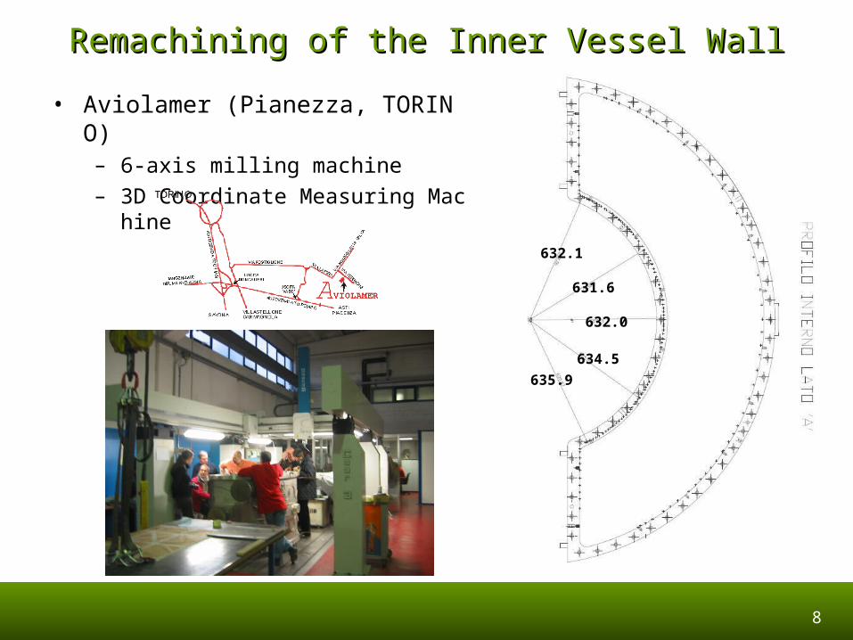
Remachining of the Inner Vessel WallRemachining of the Inner Vessel Wall
• Aviolamer (Pianezza, TORINO)– 6-axis milling machine
– 3D Coordinate Measuring Machine
632.1
631.6
632.0
634.5
635.9
9
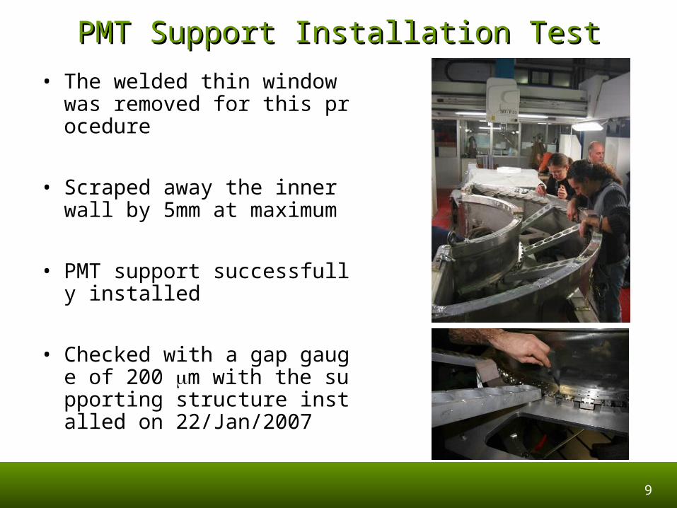
PMT Support Installation TestPMT Support Installation Test
• The welded thin window was removed for this procedure
• Scraped away the inner wall by 5mm at maximum
• PMT support successfully installed
• Checked with a gap gauge of 200 m with the supporting structure installed on 22/Jan/2007
10
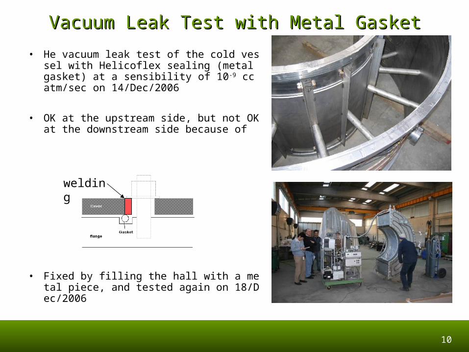
Vacuum Leak Test with Metal GasketVacuum Leak Test with Metal Gasket
• He vacuum leak test of the cold vessel with Helicoflex sealing (metal gasket) at a sensibility of 10-9 cc atm/sec on 14/Dec/2006
• OK at the upstream side, but not OK at the downstream side because of
• Fixed by filling the hall with a metal piece, and tested again on 18/Dec/2006
welding
11
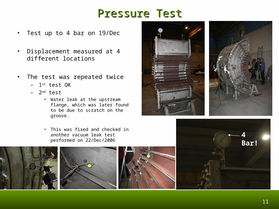
Pressure TestPressure Test
• Test up to 4 bar on 19/Dec
• Displacement measured at 4 different locations
• The test was repeated twice– 1st test OK
– 2nd test• Water leak at the upstream flange,
which was later found to be due to scratch on the groove.
• This was fixed and checked in another vacuum leak test performed on 22/Dec/2006 4 Bar!
12
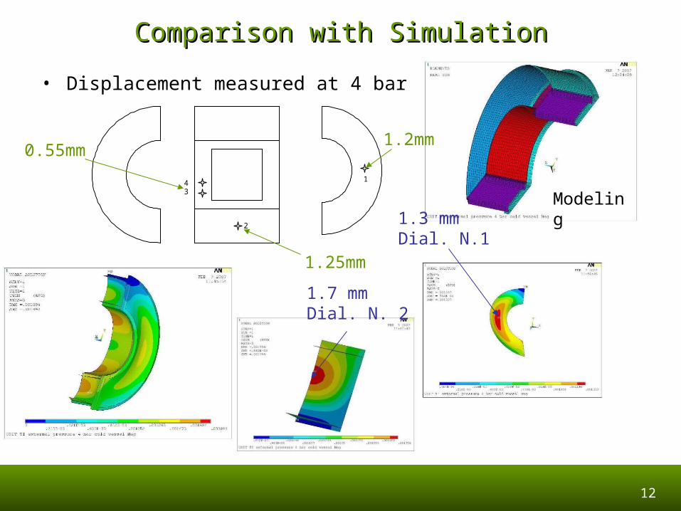
Comparison with SimulationComparison with Simulation
• Displacement measured at 4 bar
1.7 mmDial. N. 2
1
2
34
1.2mm
1.25mm
0.55mm
Modeling1.3 mmDial. N.1
13
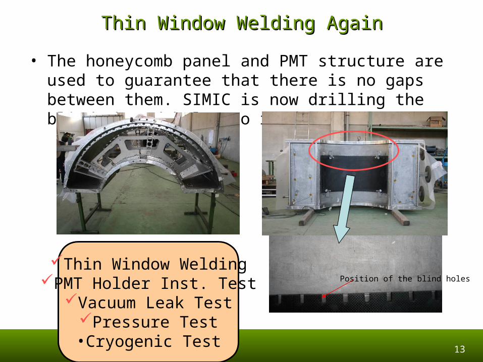
Thin Window Welding AgainThin Window Welding Again
• The honeycomb panel and PMT structure are used to guarantee that there is no gaps between them. SIMIC is now drilling the blind thread holes to restrain the panel.
Position of the blind holes
Thin Window WeldingPMT Holder Inst. TestVacuum Leak Test
Pressure Test•Cryogenic Test

Honeycomb Panel Honeycomb Panel ProductionProduction
15
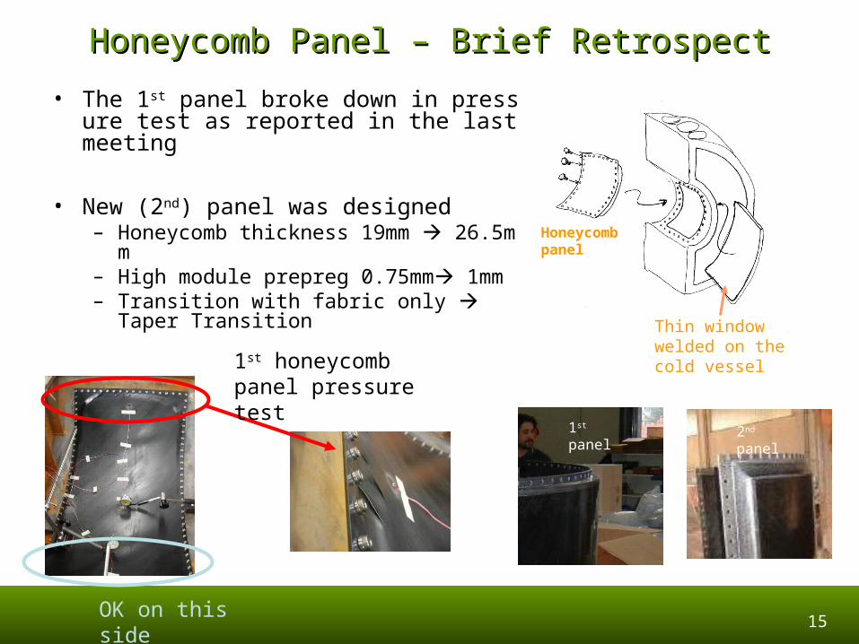
Honeycomb Panel – Brief RetrospectHoneycomb Panel – Brief Retrospect
OK on this side
• The 1st panel broke down in pressure test as reported in the last meeting
• New (2nd) panel was designed– Honeycomb thickness 19mm 26.5mm– High module prepreg 0.75mm 1mm– Transition with fabric only Taper
Transition
Thin window welded on the cold vessel
Honeycomb panel
1st honeycomb panel pressure test
1st panel 2nd panel
16
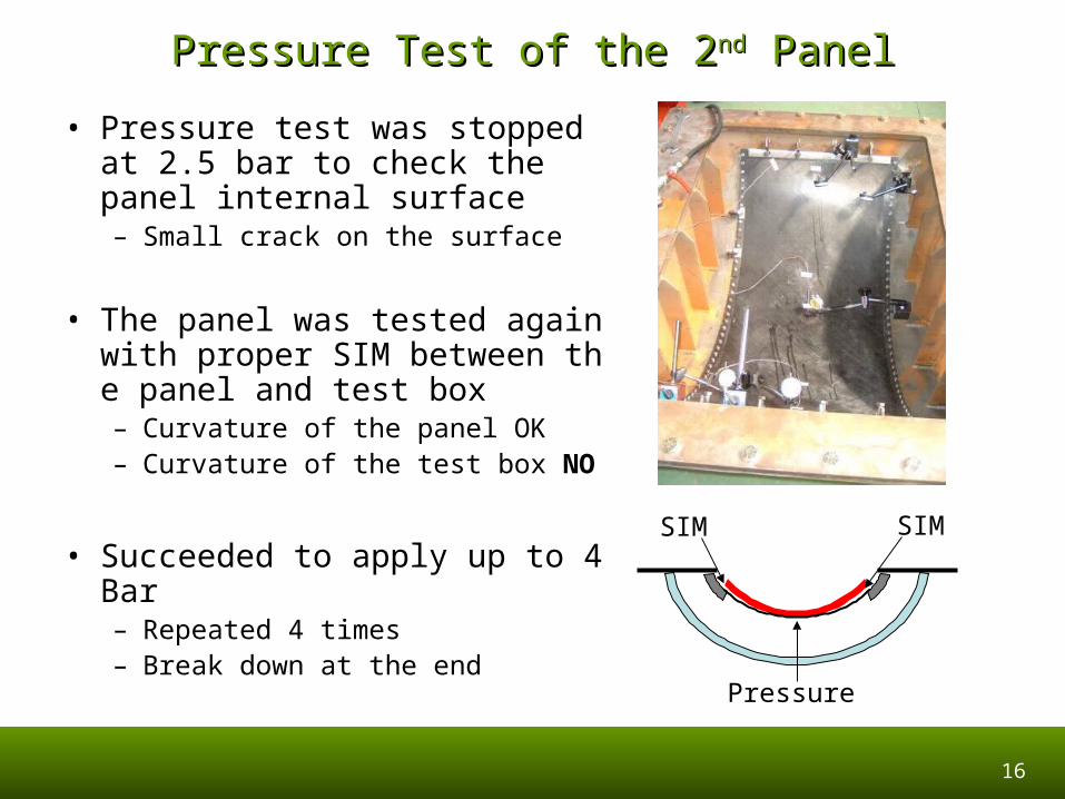
Pressure Test of the 2Pressure Test of the 2ndnd Panel Panel
• Pressure test was stopped at 2.5 bar to check the panel internal surface– Small crack on the surface
• The panel was tested again with proper SIM between the panel and test box– Curvature of the panel OK– Curvature of the test box NO
• Succeeded to apply up to 4 Bar– Repeated 4 times– Break down at the end
Pressure
SIM SIM
17
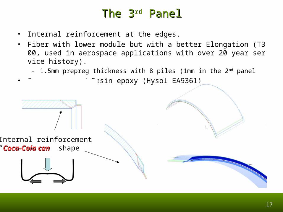
The 3The 3rdrd Panel Panel
• Internal reinforcement at the edges.
• Fiber with lower module but with a better Elongation (T300, used in aerospace applications with over 20 year service history).
– 1.5mm prepreg thickness with 8 piles (1mm in the 2nd panel
• Space-approved Resin epoxy (Hysol EA9361)
Internal reinforcement“Coca-Cola canCoca-Cola can” shape
18
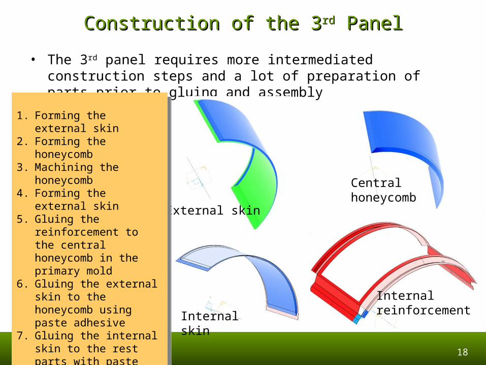
Construction of the 3Construction of the 3rdrd Panel Panel
• The 3rd panel requires more intermediated construction steps and a lot of preparation of parts prior to gluing and assembly
Centralhoneycomb
Internal reinforcementInternal skin
External skin
1. Forming the external skin2. Forming the honeycomb3. Machining the honeycomb4. Forming the external skin5. Gluing the reinforcement
to the central honeycomb in the primary mold
6. Gluing the external skin to the honeycomb using paste adhesive
7. Gluing the internal skin to the rest parts with paste adhesive
TTwo additional moldswo additional molds ar are necessarye necessary
19
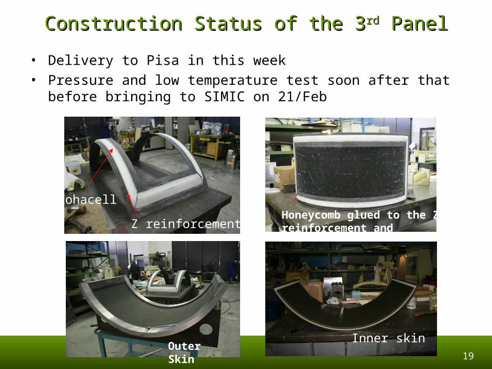
Construction Status of the 3Construction Status of the 3rdrd Panel Panel
• Delivery to Pisa in this week• Pressure and low temperature test soon after that before bringing to
SIMIC on 21/Feb
Rohacell
Z reinforcementHoneycomb glued to the Z reinforcement and rohacell
Inner skinOuter Skin
20
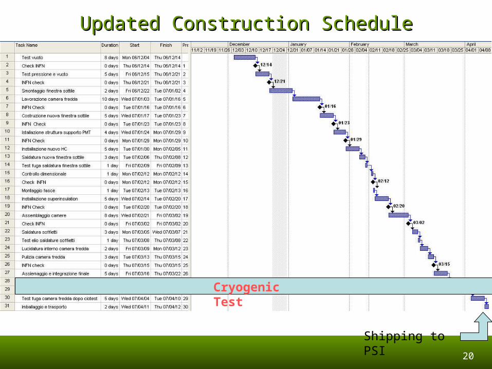
Updated Construction ScheduleUpdated Construction Schedule
Shipping to PSI
Cryogenic Test

Detector PreparationDetector Preparation
Xenon StorageCables and Related ElectronicsNaI Detector for Pi0 Calibration
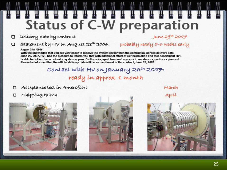
C-W Proton Acc Peter’s PresentationNickel 9 MeV Gamma Generator
22
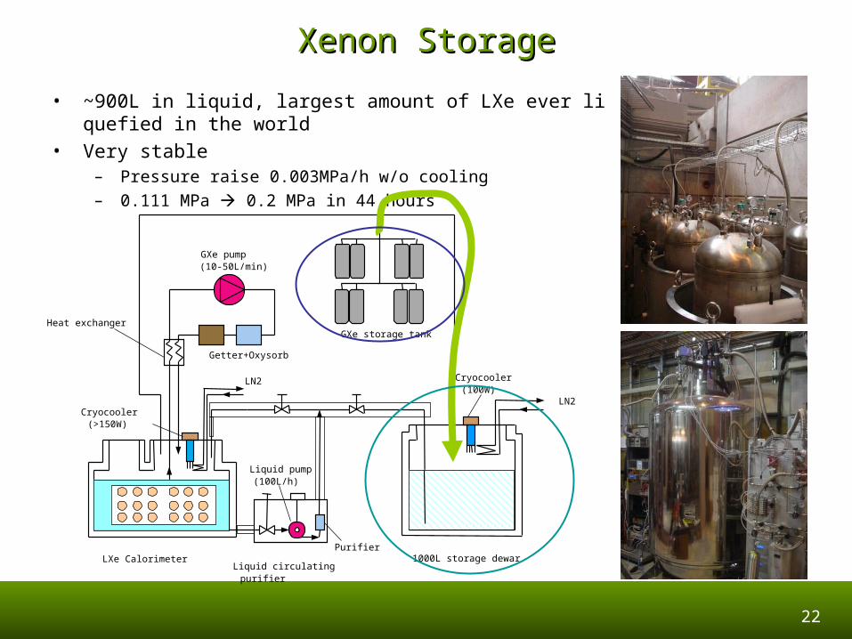
Xenon StorageXenon Storage
• ~900L in liquid, largest amount of LXe ever liquefied in the world
• Very stable– Pressure raise 0.003MPa/h w/o cooling
– 0.111 MPa 0.2 MPa in 44 hours
LXe CalorimeterLiquid circulating purifier
Liquid pump (100L/h)
Purifier1000L storage dewar
Cryocooler (100W)
LN2
LN2
Getter+Oxysorb
GXe pump (10-50L/min)
GXe storage tank
Cryocooler (>150W)
Heat exchanger
23
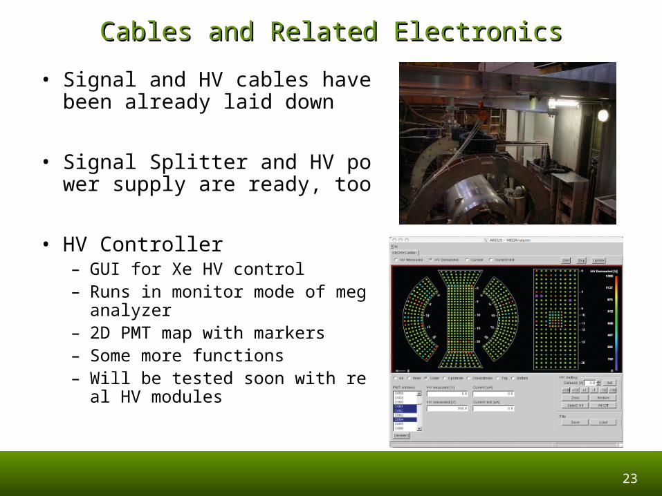
Cables and Related ElectronicsCables and Related Electronics
• Signal and HV cables have been already laid down
• Signal Splitter and HV power supply are ready, too
• HV Controller– GUI for Xe HV control– Runs in monitor mode of meganal
yzer– 2D PMT map with markers– Some more functions– Will be tested soon with real HV m
odules
24
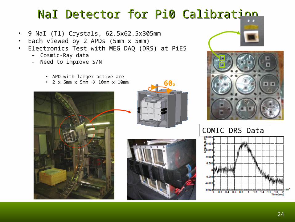
NaI Detector for Pi0 CalibrationNaI Detector for Pi0 Calibration
• 9 NaI (Tl) Crystals, 62.5x62.5x305mm• Each viewed by 2 APDs (5mm x 5mm)• Electronics Test with MEG DAQ (DRS) at PiE5
– Cosmic-Ray data– Need to improve S/N
• APD with larger active are• 2 x 5mm x 5mm 10mm x 10mm 60o
COMIC DRS Data
25
26
27
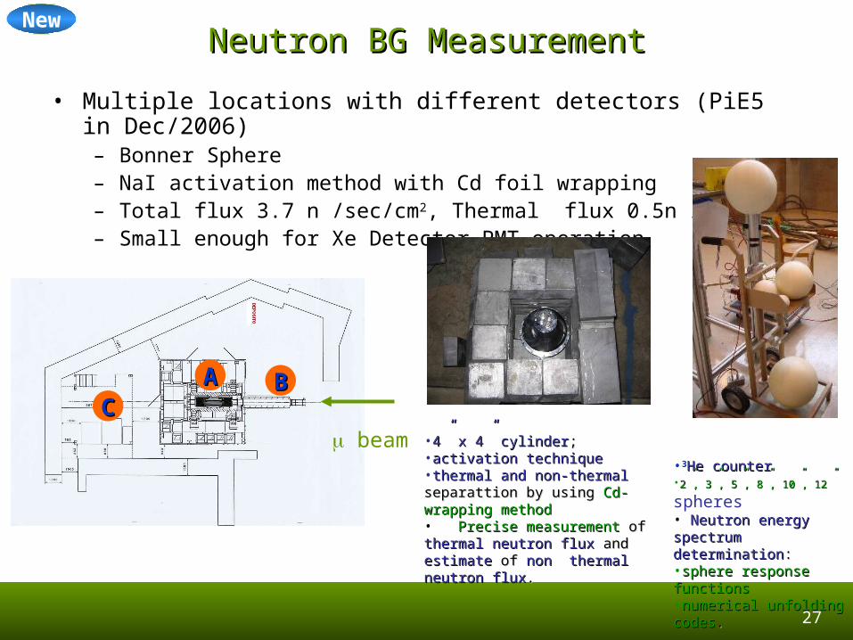
Neutron BG MeasurementNeutron BG Measurement
• Multiple locations with different detectors (PiE5 in Dec/2006)– Bonner Sphere– NaI activation method with Cd foil wrapping– Total flux 3.7 n /sec/cm2, Thermal flux 0.5n /sec/cm2
– Small enough for Xe Detector PMT operation
AACC
BB
beam •4” x 4” cylinder4” x 4” cylinder;;•activation techniqueactivation technique•thermal and non-thermal thermal and non-thermal separattion by using separattion by using Cd-wrapping Cd-wrapping methodmethod• Precise measurement Precise measurement of of thermal thermal neutron fluxneutron flux and and estimateestimate of of non non thermal neutron fluxthermal neutron flux..
•33He counterHe counter•2”, 3”, 5”, 8”, 10”, 12”2”, 3”, 5”, 8”, 10”, 12” spheres• Neutron energy spectrum Neutron energy spectrum determinationdetermination: : •sphere response sphere response functionsfunctions•numerical unfolding numerical unfolding codescodes..
New
28
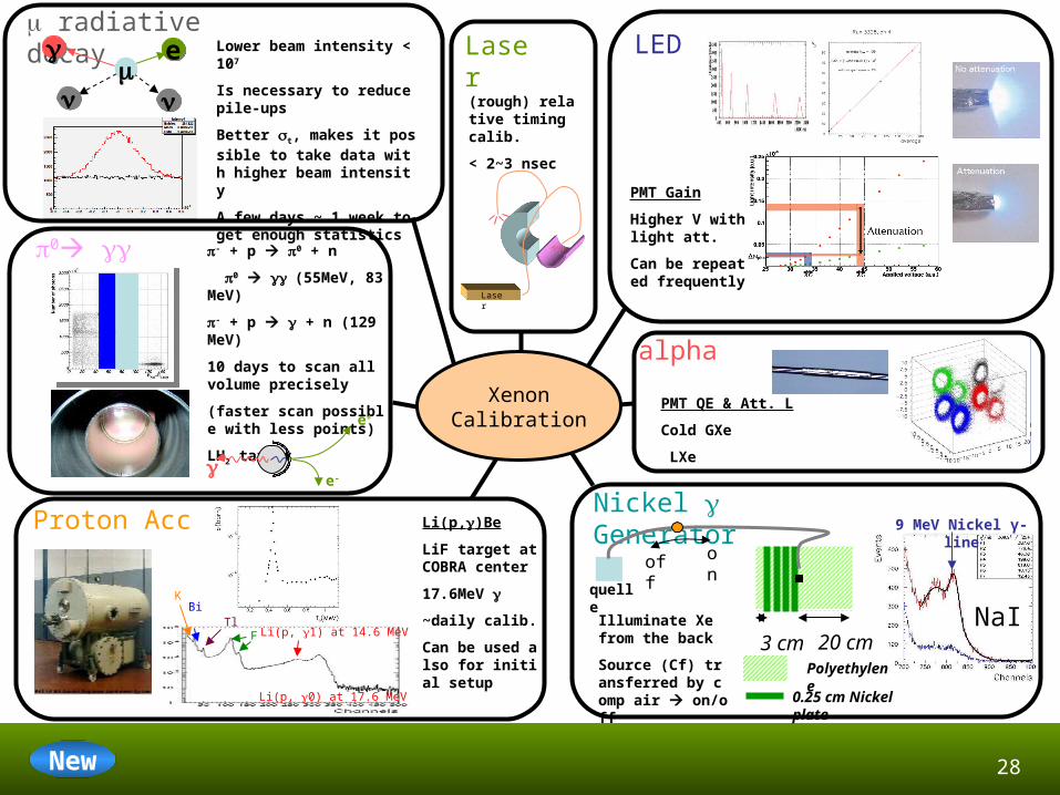
LED
PMT Gain
Higher V with light att.
Can be repeated frequently
alpha
PMT QE & Att. L
Cold GXe
LXe
Laser
Laser
(rough) relative timing calib.
< 2~3 nsec
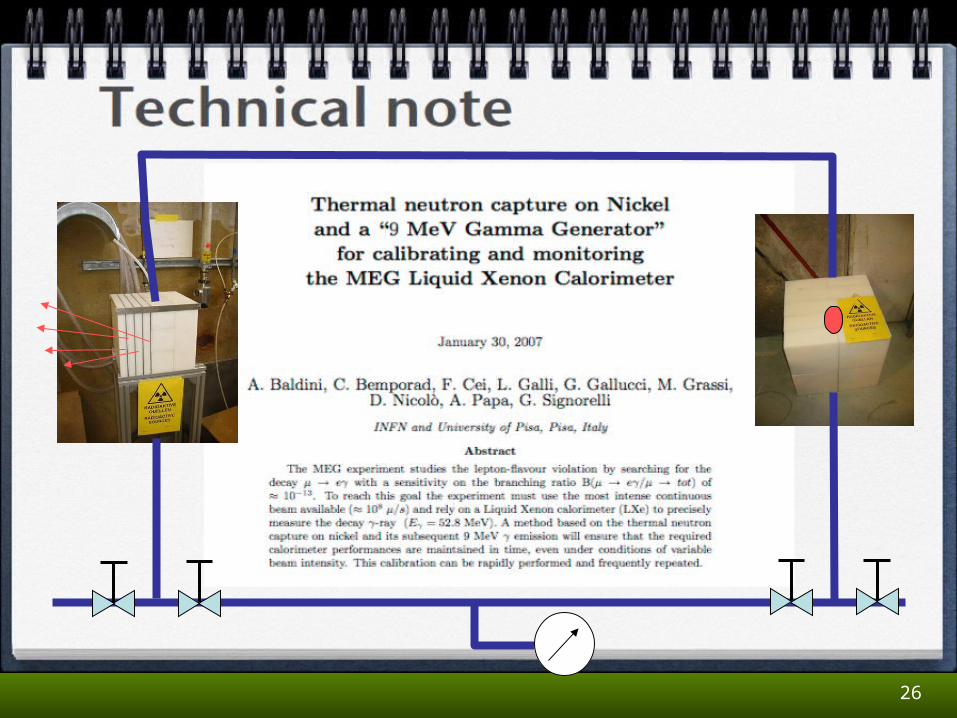
Nickel Generator 9 MeV Nickel γ-line
NaI
Polyethylene
0.25 cm Nickel plate
3 cm 20 cm
quelle
onoff
Illuminate Xe from the back
Source (Cf) transferred by comp air on/off
Proton Acc Li(p,)Be
LiF target at COBRA center
17.6MeV
~daily calib.
Can be used also for initial setup
KBi
TlF
Li(p, 0) at 17.6 MeV
Li(p, 1) at 14.6 MeV
radiative decay
0 - + p 0 + n
0 (55MeV, 83MeV)
- + p + n (129MeV)
10 days to scan all volume precisely
(faster scan possible with less points)
LH2 target
e+
e-
ee
Lower beam intensity < 107
Is necessary to reduce pile-ups
Better t, makes it possible to take data with higher beam intensity
A few days ~ 1 week to get enough statistics
XenonCalibration
New
29
After the detector is ready,
1. PMT HV adjust, gain calibration, and -source (and Cosmic-Ray) data acquisition (2 Weeks)
2. Proton Acc DAQ (2 Weeks)
3. 0 run (3 Weeks, 10 Days full DAQ)
4. Radiative decay run with lower beam intensity (2 Weeks)
After the detector is ready,
1. PMT HV adjust, gain calibration, and -source (and Cosmic-Ray) data acquisition (2 Weeks)
2. Proton Acc DAQ (2 Weeks)
3. 0 run (3 Weeks, 10 Days full DAQ)
4. Radiative decay run with lower beam intensity (2 Weeks)
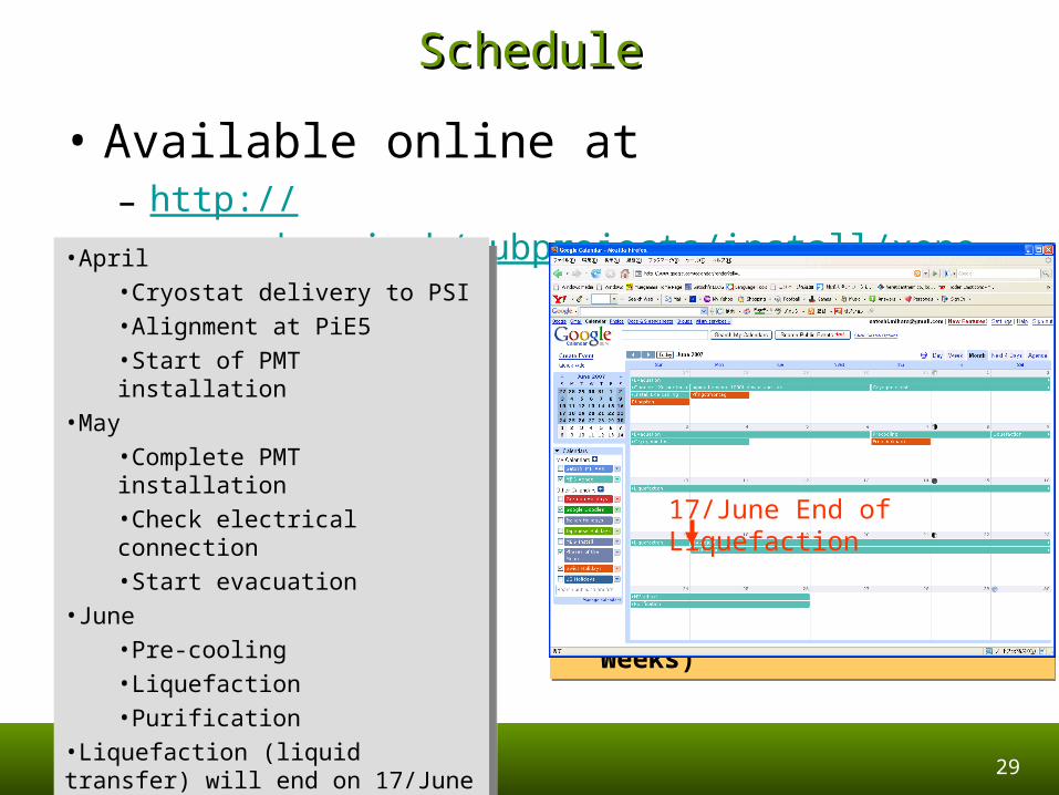
ScheduleSchedule
• Available online at– http://meg.web.psi.ch/subprojects/install/xenon.html
•April•Cryostat delivery to PSI •Alignment at PiE5•Start of PMT installation
•May•Complete PMT installation•Check electrical connection•Start evacuation
•June•Pre-cooling•Liquefaction •Purification
•Liquefaction (liquid transfer) will end on 17/June
•April•Cryostat delivery to PSI •Alignment at PiE5•Start of PMT installation
•May•Complete PMT installation•Check electrical connection•Start evacuation
•June•Pre-cooling•Liquefaction •Purification
•Liquefaction (liquid transfer) will end on 17/June
17/June End of Liquefaction
30
SummarySummary
• Cryostat construction– Many problems occurred, but they are getting solved one by one– Honeycomb panel will be delivered to Pisa in this week and
tested before bringing it to SIMIC– Cryostat delivery to PSI in April after a cryogenic test
• Detector preparation is in good condition– Calibration procedures
• pi0• C-W Acc• Nickel
– Neutron measurement performed again• BG level is expected to be small enough for the xenon detector
operation


