
J. S. MundreyFormer
Additional Member (Civil Engineering)Railway Board, Ministry of Railways.
Prologue
RITES Journal 7.1 January 2010
Tracking for High-Speed Trains in India
Concept of High-Speed Train
The council of the European Union in their directive no. 96/48/EC has definedthe term “High Speed” covering all railway express services operated at speeds in the200 to 300 km/h range. This includes railway lines:
i) Built specially for high speed generally equal to or greater than 250km/h.
ii) Specially upgraded for high speed travels of the order of 200 km/h.
The provision of a High Speed service is not restricted to reducing journeytimes. Its undoubted success is also due to the quality associated with High Speedtravel, viz:
• The frequency of service,• Regular-interval timetables,
Indian Railways have drawn up ambitiousplans for developing high speed trainsystems in India. The Author, who is anexpert in track structure and bridges, hasbrought out the different track structuresneeded for operation of high speed trains.
Various types of tracks, both ballastedand ballast-less track structures, havebeen covered.
A very informative Article indeed.- Editor

7.2 Tracking for High-Speed Trains in India
• A high level of comfort,• A pricing structure adapted to the needs of customers,• Complementarity with other forms of transport,• More on-board and station services.
A High Speed system is designed to incorporate the whole range of serviceswhich the customer has come to expect when traveling on High Speed trains, includingboth pre-travel services (information, ticket purchasing, seat reservations, etc.) andpost-travel ones (after-sales service).
High-speed railways, in addition to providing a high level of mobility of people,are greatly advantageous as an environmentally friendly means of transport.
Transport is responsible for 25% of the world’s carbon dioxide (CO2)emissions, with 80 to 90% coming from cars and highway trucks, and only 2% fromrail. Moreover, emission levels are increasing faster than technological progress dueto the total dependence of road and air transport on oil, and the continuing growth oftraffic. On High-Speed railways the energy consumption per passenger-kilometer isthree and half times less than for a bus, five times less than for air and ten times lessthan that for a private car.
The social cost of noise, dust, carbon dioxide, nitric oxide and sulfur oxideemission for high-speed rail is one fourth of road transport and one-sixth for air. Itrequires the construction of an eight-lane highway to provide the same capacity as adouble track high-speed railway line.
Table 1 gives a list of some of the high-speed lines operating at a maximumspeed of 200 Km/h and above with a start-to-stop average speed exceeding 150Km/h.
Table 1 : Start-to-stop Runs Exceeding 150 Km/h
Country & Train From To Distance AverageSpeed limit km speedin km/h km/h
France 320 TGV Lorraine Champagne- 167.6 271.8mph TGV ArdenneJapan 300 Nozomi Hiroshima Kokura 192.0 256.0Belgium 300 Thalys Brussels Valence 831.7 236.5
Midi TGVGermany 300 ICE Frankfurt Siegburg/ 143.3 226.3
Flughafen BonnSpain 300 AVE Madrid Zaragoza 307.2 236.3
Atocha Delicias
Table contd.

J. S. Mundrey 7.3
Sweden 200 X2000 Skovde Sodertalje Syd 277.0 173.1South Korea 300 KTX Seoul Main Daejeon 160.0 200.0UK 300 Class 395 Ebbsfleet Ashford 53.8 179.3
International InternationalItaly 250 Eurostar Roma Firenze SMN 261.1 168.4
TerminiUSA 240 Acela Baltimore Wilmington 110.1 161.1
Express PennFinland 200 Pendolinos Tikkurila Tampere 177.0 151.7China 200 High speed Beijing Tianjin 118.0 236.0
C classTaiwan 300 Train 598 Chiayi Taichung 85.9 245.4Austria 200 Railjet St.Polten Linz Hbf 122.7 153.4
Hbf
Technologies for High-Speed Operations
The following two distinct technologies have been adopted for high-speedoperation; these are:
i) Improvement of the conventional railway operational system.ii) Construction of dedicated High-Speed corridors.
Improvement of the conventional Railway Operational System : Inadopting this technology the hindrances existing in the operation of high-speed areremoved to the extent possible. These hindrances are in the form of :
a. Tight horizontal curves – The centrifugal forces generated on the curves,vary with the square of the speed. The curves are therefore required to beeased out to keep the centrifugal forces within a manageable limit.
b. Vertical Curves – The desirable values of radii of vertical curves for high-speed operation are much higher.
c. Level crossing/Grade Separations – For high-speed operation, all levelcrossings are required to be replaced by suitable grade separation works.
d. Fencing – On high-speed lines trespassing on tracks cannot be permitted.Thus the entire high-speed line has to be fenced.
e. Track Geometry:- Very close tolerances in track geometry are requiredto be maintained requiring sturdy track layouts and sophisticated trackmaintenance and monitoring system.
The problem in respect to tight curves has, to some extent, been solved byadopting tilting train technology.

7.4 Tracking for High-Speed Trains in India
Tilting Train Technology
All along, since the advent of the railway transportation system, the maximumpermissible speed on the railway lines has been governed by the cant (super elevation)and cant deficiency values. The development of bogie tilting technology, in whichvehicles are tilted depending upon the degree of curvature, has opened a new era ofhigh-speed operation. The tilting of the bogies is achieved by utilizing hydraulic orpneumatic power, while lately electric power is also being utilized. (Fig. 1)
What tilt achieves
Tilting trains exploit the fact that speed through curves is principally limitedby passenger comfort, and not by either lateral forces on the track or the risk ofoverturning. The principles and basic equations related to tilting are well known.
Two primary decisions need to be made. The first is the maximum tilt angleto be provided (ètilt); this is based upon the mechanical design of the vehicle. Thesecond decision is what cant deficiency the passengers should experience on aconstant radius curve (èCD tilt), which is of primary importance to comfort.
Given these two decisions, and the value of cant deficiency that applies forthe non-tilting case (èCD non-tilt), it is possible to derive an equation for the increasein curving speed, or speed-up, offered by tilt:
Vtilt sin (ècant + ètilt + èCD tilt ) —————— = √√√√√ —————————————————
Vnon-tilt sin (ècant + èCD non-tilt)
Maximum track cant is usually 6°, and typically 6° of cant deficiency isspecified for a non-tilting train. Applying 9° of tilt and with a cant deficiency of 6° forthe tilting train, the calculation indicates a speed-up of 32%.
In the light of the above facts tilting trains speed up the trains by about 30%.It is however important to design the transition curves properly, so as to ensure thecomfort level to be within the acceptable limit.
Dedicated High-Speed Corridors and their Construction Parameters
For High-Speed operation exclusive corridors have been designed andconstructed. On these corridors construction parameters have been appropriatelyselected for smooth, efficient and safe operation at the designated speed. Theconstruction parameters, which need special attention on these corridors, are:
a. Horizontal Curves: their radius, cant, cant-deficiency etc.– easiestpossible curves are provided on high-speed corridors.

J. S. Mundrey 7.5
b. Ruling Gradient : As the High-Speed trains are lighter in load and areprovided with high tractive power, steeper gradients can be allowed onhigh-speed lines.
c. Vertical curves : For better passenger comfort, gentler vertical curvesare provided on high-speed lines as compared to that adopted onconventional lines.
d. Spacing of tracks : On high-speed tracks, provision of wider center-to-center spacing for double lines is important in view of the higher airpressure generated during the crossing of the trains.
e. Track Structure : Both ballasted and ballast-less track structures havebeen adopted on high-speed lines. The first, high-speed line, New Toikadoline (Tokyo to Osaka) has ballasted track construction. High-speed linesin France and Spain have generally adopted ballasted track construction.Germany and South Korea have also adopted ballasted track structureon some of their high-speed lines. There is however a positive trendtowards the adoption of ballast-less track for high-speed lines.
The merits and demerits of the two types of track structures have beendiscussed in the succeeding paragraphs.
Ballasted Track Structure for High Speed (Fig. 2)
Ballasted track structure is a simple structure consisting of rails, sleepers,rail-to-sleeper fastening system and ballast. Well-compacted subgrade and an efficientdrainage system helps in the maintenance of ballasted track structure to closergeometrical tolerances, an essential requirement for high-speed operation.
Main Characteristics of Ballasted Track
In ballasted track, impact forces generated by the oncoming loads aredissipated by the elastic deformation of ballast and the formation underneath,approximately 50% by each of them. In this process, there is also permanent settlementof ballast and formation. In course of time, the ballast gets pulverized/contaminated,loosing its elastic property. Periodical building and recuperation of ballast is requiredfor the ballast to function effectively. Deep screening of ballast is carried out whenfiner particles in the ballast increase the specified limit. The advantages anddisadvantages of adoption of ballasted track for high-speed operation are as under:
Advantages of ballasted track over ballast-less track are:
(i) Known and proven method, up to a speed of 350 Kmph.(ii) Low construction cost.

7.6 Tracking for High-Speed Trains in India
(iii) Availability of highly mechanized construction technology.(iv) Good elasticity for efficient absorption of noise and vibrations.(v) Reasonably good maintainability with track machines.(vi) Less sensitive to construction defects.
Disadvantages of ballasted track when compared to ballast-less track are:
(i) Track tends to move both vertically and laterally- requires frequent tamping.(ii) Limited uncompensated lateral acceleration possible due to limited lateral
ballast resistance.(iii) At speeds of 275 Kmph and above, ballast churns up damaging both rail
and wheels.(iv) Elasticity gets affected with pulverization and contamination; periodic
deep screening required.
Main Characteristics of Ballast-less Track
Ballast-less track rests on solid foundation with no or very little settlement.The elastomeric pads replace the ballast. No maintenance is required except periodicalreplacement of elastic components after their life span is over. There is considerablescope for the reduction of cost of construction of track structure when laid in tunnelsor on viaducts.
Some of the advantages of ballast-less track are:
(i) High operational availability- time required for maintenance is almost nil.
(ii) Long lasting good track geometry.
(iii) Long life of track structure, 40 to 50 years.
(iv) Predictable behavior of track components and thus of track geometry.
(v) High resistance to lateral and longitudinal forces permitting steepergrade and higher speed.
(vi) Regularity of the rheological (transmission of electric current)properties.
(vii) Quiet vehicle running, even at high speed.
Ballast-less tracks however suffers from the following drawbacks:
(i) Comparatively higher construction cost, particularly when laid on earthformation.
(ii) Highly sensitive to construction defects.
(iii) Mechanization of track construction and renewals still in infant stage.

J. S. Mundrey 7.7
Design Philosophy of Ballast-less Track
Ballast-less track assemblies are expected to provide the same degree ofelasticity in all directions as is available in ballasted track. This is necessary tocontain the static and dynamic forces within acceptable limits. Ballast-less trackassemblies are also expected to perform the following two important functions.
(i) Dampen the high frequency vibrations of the rail. For that purpose, allballast-less track assemblies have an elastomeric rail pad under the railseat, on which the rail is expected to be under compression at all times.This is similar to the arrangement with the concrete sleepers in ballastedtrack.
(ii) A medium to distribute the oncoming loads and absorb the energygenerated, functions which are performed by the ballast in the ballastedtrack. This function is performed by incorporating an additional,comparatively softer elastomeric pad in the assembly.
The above-mentioned basic requirements of the ballast-less track can bemet with by simple assemblies shown in Fig. 3, 4 & 5.
Further developments in the ballast-less track technology have been promptedby the following considerations:
a) Construction of track with close tolerances – It has to be noted thatballast-less track requires great precision during construction, as anychange in level or alignment is difficult to be carried out at a later stage.
b) Mechanization of construction – In developed countries, labour costsbeing very high, systems have been developed to mechanize the trackconstruction to the extent possible. Pre-fabrication of track componentis one way of reducing labour costs and for increasing the speed ofconstruction
These technologies have been discussed in subsequent paragraphs.
Construction parameters as adopted on exclusive High-Speed Corridors
The geometric parameters as adopted by various world railways on theirhigh-speed corridors are as follows:
(i) Curves, Horizontals and Vertical
Horizontal curves are in the range of 7000m to 10000m. For standard gaugetrack, radius and other curve parameters as adopted in various countries are given inTable 2.

7.8 Tracking for High-Speed Trains in India
Table 2 : Curve Parameters
Country
Parameters France Germany Spain Korea Japan
Speeds km/h 300/350 300 350 300/350 350Radius of HorizontalCurves (m) 10 000 7 000 7000 7000 4000Maximum cantin (mm) 180 170 150 130 180Cant deficiency 85 150 100 65 50Maximum grade(mm/m) 35 40 12.5 25 15Cant gradient(mm/s) 50 34.7 32 NA NAMinimum verticalradius (m) 16 000 14 000 24 000 NA 10 000
(NA = Not Available)
Spacing of Tracks
Minimum distance between tracks centers adopted by some of the high-speed networks using standard gauge are given in Table 3.
Table 3 : Minimum Distance Between Tracks
Country Minimum distance between tracks (m)at the following speed
300 Km/h 350 Km/hFrance 4.2 4.5Germany 4.5 4.5Italy 5.0 5.0Spain 4.3 4.7Japan 4.3 4.3
Indian Railways provide a centre to centre spacing of 5.35 m between trackson broad gauge for new construction projects, which is sufficient for a high-speedcorridor.
Ballast-Less Track Technologies of High-Speed Railway Lines
The following types of ballast-less tracks have been adopted by various worldrailway systems on their high-speed tracks.
i) Slab track design based on the design adopted on Shinkansen, Japan –Fig .6

J. S. Mundrey 7.9
In this system, pre-cast cement concrete panels about 5 m long and 2.34 mwide and 160 mm thick support the rails at the precise locations. Specially designedmixture of cement and maxphalt about 50 mm thick is introduced between the twoconcrete surfaces of base concrete and the top concrete panel. This mix provides amedium for vertical adjustment and helps in reducing track vibrations. In Japan, railsare fixed on the top slab with standard KAWA type fastening system, having a rail-pad and also an elastomeric pad under the base plate. The rail fastening systemallows considerable scope for vertical and lateral adjustment. The cement maxphaltmix layer can be suitably adjusted to accommodate any settlement of formation.
Similar system with certain modifications has been evolved by M/s Max Boglcalled “Slab track system FF-Bogl”. Italian and Chinese railways have also evolved asimilar system for their high-speed lines.
ii) REHDA Ballast-less Track System (Fig. 7)
In this system, the sleeper with ordinary reinforcement (without pre stressing)together with the concrete bed that encloses it, constitutes a homogenous ballast-less track structure. Various versions of REHDA system have been developed. Thelatest among them is REHDA 2000. The REHDA 2000 is installed as a top-downsystem, with the help of service rails. The sleepers are assembled together with therails to form a track framework, which is installed at proper position with the use of aspecial adjustment mechanism. The track-supporting layer of concrete is pouredonly after final alignment and leveling. This system has been used on a number ofnew high-speed lines in Germany. Recently, it has also been used in the stationareas for turnouts installation on Taiwan’s high-speed line.
iii) Low Vibration Track (LVT) System (Fig. 8)
LVT System developed by Mr. Roger Sonneville, comprises of concrete blocks,resilient pads placed under the blocks and rubber boots encased in a second pourconcrete. The rails are fixed in position with the concrete blocks adopting the standardFrench Nabla elastic clips. Pandrol, Vossloh or other similar elastic fastening systemcan also be used. No adjustment is possible in the position of concrete blocks afterthe second pour concrete. This system has been found true to its reputation of allowingvery low vibrations from the railway tracks to adjoining structures. The system hastherefore been extensively used on railway tracks in tunnel including the channeltunnel and also the tunnels on the Taiwan high-speed lines.
iv) Solid Slab Track-System NBO (Fig. 9)
The solid slab “track-system NBO” is similar to the paved concrete trackevolved in UK, sometime in 1970’s, where a specially designed concrete paver wasused to lay the concrete slab to close tolerances. In the NBO system concrete paverleaves a groove in which rails with their elastic fastening system are accurately placed,

7.10 Tracking for High-Speed Trains in India
adopting top-bottom construction technology. This system does not use sleepersand has the following main features:
1) Concrete slab laid to tight tolerances2) Laying the rails complete with fastenings3) Use of rapid hardening grout (jointing compound)
This system, which is patented by M/s ThyssenKrupp, has been approvedby the Technical University of Munich, Germany and has been laid on some high-speed lines in Germany and in South Korea.
v) Edilon Embedded Rail System – Fig. 10
In this system rails are embedded in position with a suitably formulatedelastomeric compound, which provides the necessary degree of elasticity. This systemis similar to the “NBU” system, where a concrete pavement is constructed leavinggrooves for the installation of rails. This system, although free from fastening component,has little scope for rail adjustment. Technical University of Munich, after carrying outnecessary laboratory tests, has cleared the system for adoption on high-speed tracks.This system has been adopted by Taiwan on their high-speed lines at Taipei station.
Ballast-less Track on Earth Formations
With limited scope for adjustments in the ballast-less track assembly, suchtracks are best suited for locations where there is no or little possibility of settlement.Viaducts and tunnels are therefore the preferred locations for ballast-less tracks
However, on account of the advantages that ballast-less track offers over theballasted track, they are being increasingly adopted in earth formations. In suchcases, the subgrade structure is properly designed to ensure minimal settlement ofthe track during service.
Figures 11 and 12 show two types of substructures, which have been adoptedon German Railways for their ballast-less track, and are reported to be giving goodservice.
Noise and Vibration Control
Railway transport system with the steel wheel running on steel rail is knownto cause environmental pollution on account of excessive noise and vibrations. Thisphenomenon becomes more pronounced when ballast-less track structure is adopted.To contain the noise and vibration levels within acceptable limits, measures are taken,which include: adoption of floating slab, provision of noise barriers, rubber bearings,resilient base plates etc. Figure 13 shows the noise and vibration control measurestaken on one of the railway lines with ballast-less track.
J. S. Mundrey 7.11
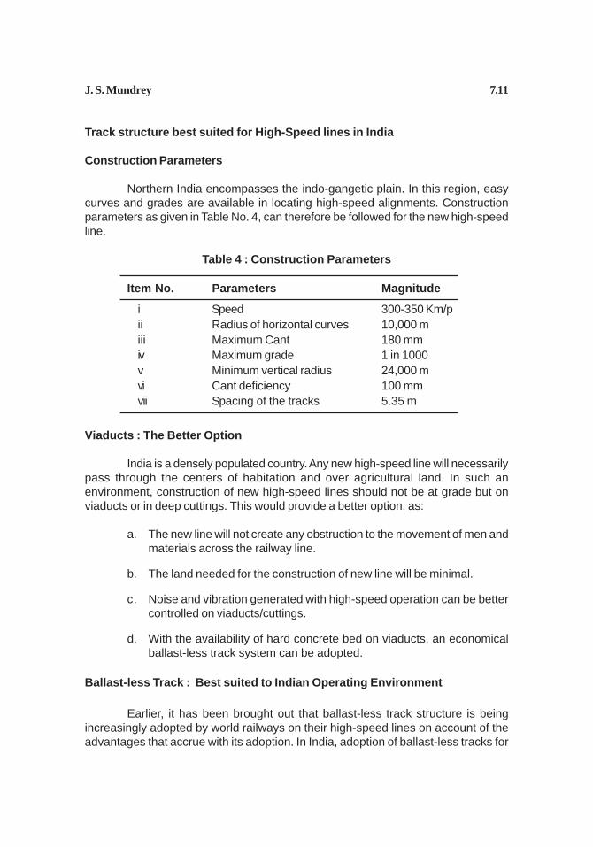
Track structure best suited for High-Speed lines in India
Construction Parameters
Northern India encompasses the indo-gangetic plain. In this region, easycurves and grades are available in locating high-speed alignments. Constructionparameters as given in Table No. 4, can therefore be followed for the new high-speedline.
Table 4 : Construction Parameters
Item No. Parameters Magnitude
i Speed 300-350 Km/pii Radius of horizontal curves 10,000 miii Maximum Cant 180 mmiv Maximum grade 1 in 1000v Minimum vertical radius 24,000 mvi Cant deficiency 100 mmvii Spacing of the tracks 5.35 m
Viaducts : The Better Option
India is a densely populated country. Any new high-speed line will necessarilypass through the centers of habitation and over agricultural land. In such anenvironment, construction of new high-speed lines should not be at grade but onviaducts or in deep cuttings. This would provide a better option, as:
a. The new line will not create any obstruction to the movement of men andmaterials across the railway line.
b. The land needed for the construction of new line will be minimal.
c. Noise and vibration generated with high-speed operation can be bettercontrolled on viaducts/cuttings.
d. With the availability of hard concrete bed on viaducts, an economicalballast-less track system can be adopted.
Ballast-less Track : Best suited to Indian Operating Environment
Earlier, it has been brought out that ballast-less track structure is beingincreasingly adopted by world railways on their high-speed lines on account of theadvantages that accrue with its adoption. In India, adoption of ballast-less tracks for

7.12 Tracking for High-Speed Trains in India
new high-speed lines is almost inescapable in view of the environmental problems,likely to be faced, with ballasted tracks. These are:
(i) With the heavy rainfall during monsoon months, it will be difficult to maintainthe desired track tolerance on ballasted tracks. Extensive tampingoperations will be needed during monsoons and after, to restore normalcy.
(ii) Ballasted tracks at high-speeds are a great environmental hazard byraising a huge cloud of dust following the movement of high-speed trains.Such tracks will be a nuisance for the habitants residing in the villages/towns located adjacent to the high-speed lines.
(iii) Ballast contamination by dust and its churning, will need more frequentballast cleaning operations.
Main Characteristics of Ballast-less Track for Indian Railways
Important constituents of ballast-less track structure will be:
a. 60 kg UIC 90 UTS rails, in continuously welded lengths. Jindal Steel andPower Limited (JSPL) has setup a new modern rail rolling mill at Raigarh,India, where 120 m long rails are being rolled. They have setup anintegrated flash-butt rail welding plant, where the rolled rails are furtherwelded into 480 m lengths. These rails when laid on high-speed linescan be converted into continuous length using mobile flash butt-weldingplant. These long rails will provide the maximum safeguard in ensuringdurable and safe track structure.
b. Sturdy high-speed turnouts with swing nose crossings.
c. Modern glued insulated joints having service life equal to the life of therail.
d. Discrete support at 60 cm c/c.
Regarding construction technology, the systems adopted by advancedcountries require deployment of heavy machinery for their construction andmaintenance. Pandrol Vipa System and Logwell Forge (India) System however canbe constructed by trained skilled labor force without the use of heavy machinery.
It will be desirable to workout the life cycle costs for various systems andadopt the best option, taking into account all the relevant factors, including construction

J. S. Mundrey 7.13
cost, maintenance cost, availability of heavy construction machinery etc. May be,more than one ballast-less track system shall have to be adopted on a line, as hasbeen done on Taiwan’s high-speed line.
Prospect of High-Speed Train Operation in India
The benefits that can be derived with the adoption of high-speed train systemsare now well recognized. Out of all the benefits, the reduced journey time has beenthe overriding consideration in the adoption of high-speed operation.
On the basis of the current experiences on world railways, it has been observedthat when the distances are between 300 to 600 kms, and the travel time by the high-speed train is less than 2-2.5 hours, the market share of passengers for the high-speed rail is atleast 75-80%. This percentage decreases dramatically when the traveltime of train increases to 4-5 hours and a round trip during the day is not possible.
Taking into account, the various factors that influence the need for high-speed train operation, Indian railways have selected the following routes for conductingpre-feasibility studies:
1) Pune-Mumbai-Ahmedabad
2) Delhi-Chandigarh-Amritsar
3) Chennai-Bangalore-Coimbatore-Ernakulam
4) Hyderabad-Dornakal-Vijayawada-Waltair
5) Haldia-Howrah
The pre-feasibility study contract for the Pune-Mumbai-Ahmedabad routehas already been awarded to an international consultancy group led by M/S Systra ofFrance. In the pre-feasibility study, apart from technical considerations, the financialmodels for the implementation of the project will also be explored.
French, Japanese, German and Spanish technologies of high-speed trainoperation are now easily available off the shelf. Once the Indian government decides,it should not take more than 4-5 years to have high-speed trains running on Indiansoil. With less than one hour of journey time, it will then be possible to live in thesalubrious climate of Chandigarh and commute to Delhi for work. High-speed trainoperation will play a significant role in the de-congestion of megalopolis towns ofDelhi, Kolkata, Mumbai, Chennai etc.

7.14 Tracking for High-Speed Trains in India
Ultra-High Speed Trains of the 21st Century- Maglev Guideway Trains
Primarily, there are two types of Maglev technologies:
• Electro Magnetic Suspension (EMS) uses the attractive magnetic forceof a magnet beneath a rail to lift the train up. German Trans Rapid hasadopted this technology. In this system, the trains do not have any wheels.
• Electro Dynamic Suspension (EDS) uses a repulsive force between twomagnetic fields to push the train away from the rail. Trials with thesesystem are going on in Japan. In this system, the vehicles must bewheeled for travel at lower speeds i.e. upto 200 km per hour. At high-speeds, the trains get levitated.
Electro Dynamic Suspension (EDS) Trains in Japan
Trials are presently going on at the 42 km Maglev test track in Japan, whichwould form part of the first maglev train to enter into commercial service for the transportof passengers between Tokyo and Osaka. These trains which will be supported andguided by concrete guide ways, both in the vertical and lateral direction, will not berunning on rails, but over concrete surface, separated by about 100 mm, by magneticlevitation. Fig. 14 shows a typical vehicle moving over a Maglev guide way.
In their movement at a speed of 550 kmph, the trains will be more akin inoperation to aeroplanes, than to conventional railways. They are provided withretractable landing wheels and horizontal guide wheels, which will come into operationwhenever the speed comes down below 200 kmph, the minimum speed to achievelevitation. The trains will be propelled using linear motor power; the 3 phase coilsforming the starter of the linear motor shall be installed in the sidewalls of the guideway.The speed is controlled by varying the frequency of the power passing through thecoils.
Various types of braking systems are being tried out to ensure that the trainscan stop reliably from the speed of 550 kmph. Aerodynamic brakes similar to thevertical flaps used in aeroplanes, have been installed over the roof of the train. Otherforms of brakes include (a) a regenerative brake, that reverses the current in theguideway coils and returns power to the power house (b) a rheostatic guideway brakewhich makes the linear motor act as a generator and (c) disc brakes fitted to theundercarriage of wheels.
The entry to the carriages will be from the top. Thus overhead platforms willbe built for the passengers to board the train.

J. S. Mundrey 7.15
Electro Magnetic Suspension – Shanghai Airport link
Transrapid magnetic levitation trains are regularly running on a transrapidtrack, built to connect Shanghai metropolitan city to its Pudong International Airport.This 30 km distance is covered in just 7 min 20 sec at an average speed of 250km/h and a top speed of 431 km/h (Fig. 15). The cost of building the 30 km Shanghaimaglev was US$ 1.2 billion.
In view of the high costs involved in maglev train operation, this system oftransport is still in its infancy.
Conclusion
In conclusion, it is seen :
� High-speed trains are being increasingly adopted on world railways, in view of themany sided advantages that they offer.
� Two distinct techniques have been adopted for high-speed operations: a)Improvement of the conventional railway system, b) Construction of DedicatedHigh-Speed corridors.
� Improvement of the conventional railway system by the adoption of tilting traintechnology offers very limited advantage in the increase of speed- only upto amaximum of 30 percent.
� To reap the full benefits of high-speed operation, Dedicated High-Speed Corridorsare being constructed. On these corridors, speeds upto 350 kms per hour arebeing achieved.
� On Dedicated High-Speed corridors, construction parameters particularly thecurves and the grades are appropriately selected for smooth, efficient and safeoperation at the designated speed.
� Both ballasted and ballast-less track structures have been adopted on worldrailways on their high-speed lines. Ballast-less track structure with many of itsplus points, particularly its long service life, safety of operation and lower lifecycle cost, is gaining favour.
� Many ballast-less track assemblies have appeared in the railway market. Thesevary from single plate assemblies, which can be constructed by skilled/unskilledlabour, to highly sophisticated systems requiring the deployment of costly trackconstruction machinery.

7.16 Tracking for High-Speed Trains in India
� Ballast-less tracks are best suited for locations where there is no or little possibilityof settlement. Viaducts and tunnels are therefore the ideal locations for ballast-less tracks.
� Ballast-less tracks, where adopted on earth formations, the subgrade structureis required to be properly designed to ensure minimal settlement of track duringservice.
� On high-speed lines, new technologies in the form of floating slabs, noise barriers,rubber bearings etc. are being adopted to contain noise and vibration levels withinthe acceptable limits.
� India, with its continental dimensions, provides a good scope for the adoption ofhigh-speed train technology, to meet the transport needs of its fast growingeconomy.
� Ballast-less track structures on viaducts will offer the best techno-economicsolution for the Indian environment.
� Ultra high-speed trains of the 21st century are the Maglev guideway trains. Thistechnology, which is still in a nascent stage, has been adopted in a limited wayfor the airport link in Shanghai, China.
� Maglev guideway trains, which can operate at over 500 km/hour may criss-crossthe world landmass in future. It may however take many years before thistechnology graduates to the desired level of efficiency, safety and economy ofoperation.
References
1. Singh, K. P. : ‘High Speed Trains Around the World : Prospects for India’,RITES Journal, April 2000.
2. Mishra, D. C. : ‘Running of High Speed Passenger Trains : The World Scenarioand the Indian Perspective’, RITES Journal, April 2003.
3. Sanjay Misra : ‘High Speed Rail Transportation and its Indian Relevance’, RITESJournal, August 2007.
4. Railway Gazette International, UK, 2009.
5. International Railway Journal.
*****


