TPS SENSOR
-Throttle Position Sensor
Technical Spec
ECOTRONS LLC
COPY RIGHTS ECOTRONS
ALL RIGHTS RESERVED
Note: If you are not sure about any specific details,
please contact us at [email protected].
Product: Throttle Position Sensor
Part #: ETS28X
Comment: All data given in this document are nominal values and
might be subject of change at any time
Index Page Revision Date Note
1 ---- First Edition 11.26.2013 V1.3
2 ---- Second Edition 12.16.2013 V1.3.1
3 ---- Third Edition 12.20.2013 V1.3.2
4 ---- Fourth Edition 7.11.2014 V1.3.3
5 ---- Fifth Edition 2.9.2016 V1.3.4
Contents
1 Characteristic
2 Applications
3 Installation instructions
4 Diagnostics and Services
5 Appendixes: Mechanical CAD Drawing
TPS Sensor technical spec-V1.3.4
1 Copy rights ECOTRONS LLC http://www.ecotrons.com
1 Characteristic
General description
This throttle position sensor (TPS) is mechanically linked to the throttle plate
and the sensing element has an arm that rotates with the throttle plate. The arm
has a contact point on the potentiometer which acts like a voltage divider.
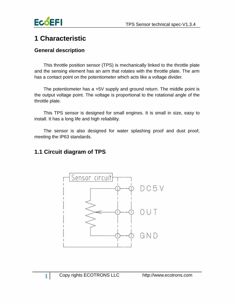
The potentiometer has a +5V supply and ground return. The middle point is
the output voltage point. The voltage is proportional to the rotational angle of the
throttle plate.
This TPS sensor is designed for small engines. It is small in size, easy to
install. It has a long life and high reliability.
The sensor is also designed for water splashing proof and dust proof,
meeting the IP63 standards.
1.1 Circuit diagram of TPS
TPS Sensor technical spec-V1.3.4
2 Copy rights ECOTRONS LLC http://www.ecotrons.com
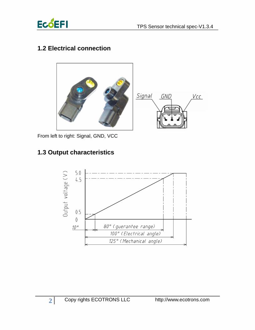
1.2 Electrical connection
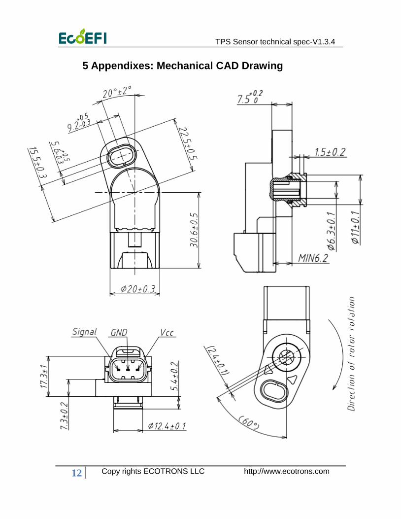
From left to right: Signal, GND, VCC
1.3 Output characteristics
TPS Sensor technical spec-V1.3.4
3 Copy rights ECOTRONS LLC http://www.ecotrons.com
2 Applications
2.1Sensor specifications
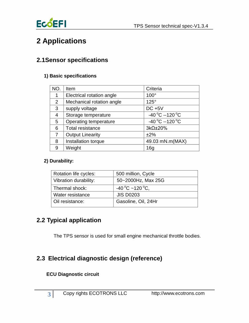
1) Basic specifications
NO. Item Criteria
1 Electrical rotation angle 100°
2 Mechanical rotation angle 125°
3 supply voltage DC +5V
4 Storage temperature -40 oC --120 oC
5 Operating temperature -40 oC --120 oC
6 Total resistance 3kΩ±20%
7 Output Linearity ±2%
8 Installation torque 49.03 mN.m(MAX)
9 Weight 16g
2) Durability:
Rotation life cycles: 500 million, Cycle
Vibration durability: 50~2000Hz, Max 25G
Thermal shock: -40 oC ~120 oC,
Water resistance JIS D0203
Oil resistance: Gasoline, Oil, 24Hr
2.2 Typical application
The TPS sensor is used for small engine mechanical throttle bodies.
2.3 Electrical diagnostic design (reference)
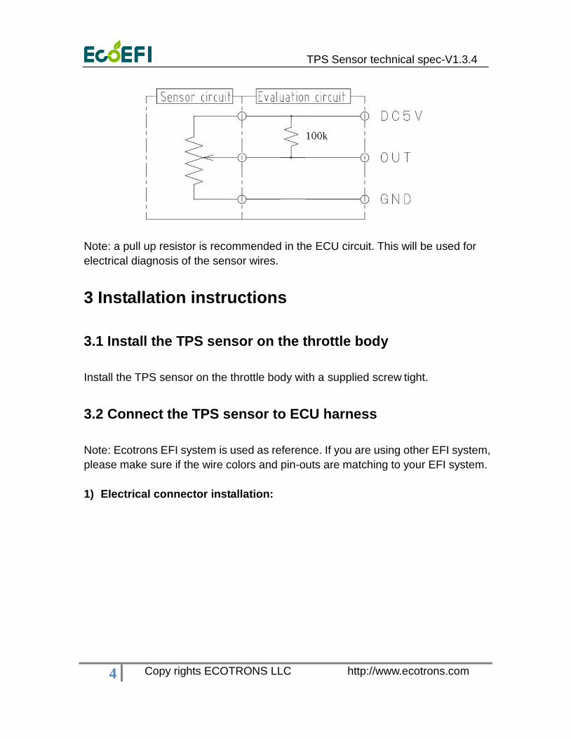
ECU Diagnostic circuit
TPS Sensor technical spec-V1.3.4
4 Copy rights ECOTRONS LLC http://www.ecotrons.com
Note: a pull up resistor is recommended in the ECU circuit. This will be used for
electrical diagnosis of the sensor wires.
3 Installation instructions
3.1 Install the TPS sensor on the throttle body
Install the TPS sensor on the throttle body with a supplied screw tight.
3.2 Connect the TPS sensor to ECU harness
Note: Ecotrons EFI system is used as reference. If you are using other EFI system,
please make sure if the wire colors and pin-outs are matching to your EFI system.
1) Electrical connector installation:
TPS Sensor technical spec-V1.3.4
5 Copy rights ECOTRONS LLC http://www.ecotrons.com
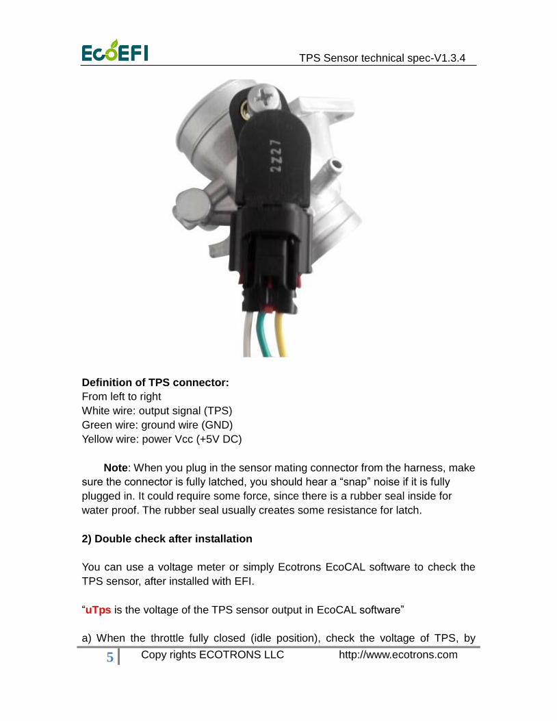
Definition of TPS connector:
From left to right
White wire: output signal (TPS)
Green wire: ground wire (GND)
Yellow wire: power Vcc (+5V DC)
Note: When you plug in the sensor mating connector from the harness, make
sure the connector is fully latched, you should hear a “snap” noise if it is fully
plugged in. It could require some force, since there is a rubber seal inside for
water proof. The rubber seal usually creates some resistance for latch.
2) Double check after installation
You can use a voltage meter or simply Ecotrons EcoCAL software to check the
TPS sensor, after installed with EFI.
“uTps is the voltage of the TPS sensor output in EcoCAL software”
a) When the throttle fully closed (idle position), check the voltage of TPS, by
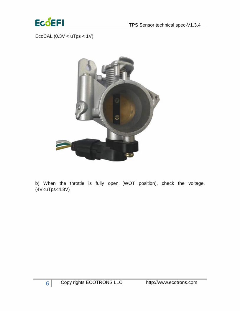
TPS Sensor technical spec-V1.3.4
6 Copy rights ECOTRONS LLC http://www.ecotrons.com
EcoCAL (0.3V < uTps < 1V).
b) When the throttle is fully open (WOT position), check the voltage.
(4V<uTps<4.8V)
TPS Sensor technical spec-V1.3.4
7 Copy rights ECOTRONS LLC http://www.ecotrons.com
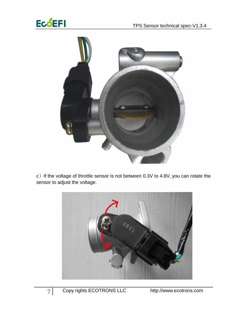
c)If the voltage of throttle sensor is not between 0.3V to 4.8V, you can rotate the
sensor to adjust the voltage.
TPS Sensor technical spec-V1.3.4
8 Copy rights ECOTRONS LLC http://www.ecotrons.com
Note: The voltage of throttle sensor is normally in the range from 0.3 to
4.8V
3.3 Installation Notes
a) TPS sensor is not water submersible proof.
b) Avoid the sensor in a dusty or muddy environment. The dust or debris that
might get into sensing element will cause deficiency of the sensor.
c) Every time a new sensor is installed or a new ECU is installed in Ecotrons
EFI system, the TPS sensor idle position and WOT position will be self-adapted.
To trigger this learning process is to create a “power fail” of ECU, meaning, with
Key On, disconnect the ECU and then key off, then reconnect the ECU.
d) Sensor mounting torque should not exceed 49.03mN * m (MAX), to
prevent the sensor damaging.
4 Diagnostics and Services
You can use Ecotrons EcoCAL software to run the diagnosis of the TPS
sensor. Power on the EFI system, and if the MIL lamp (LED) is on, it means there
is an error in the system. Please use EcoCAL to read DTC if ECU reports a DTC
code for TPS sensor failure.
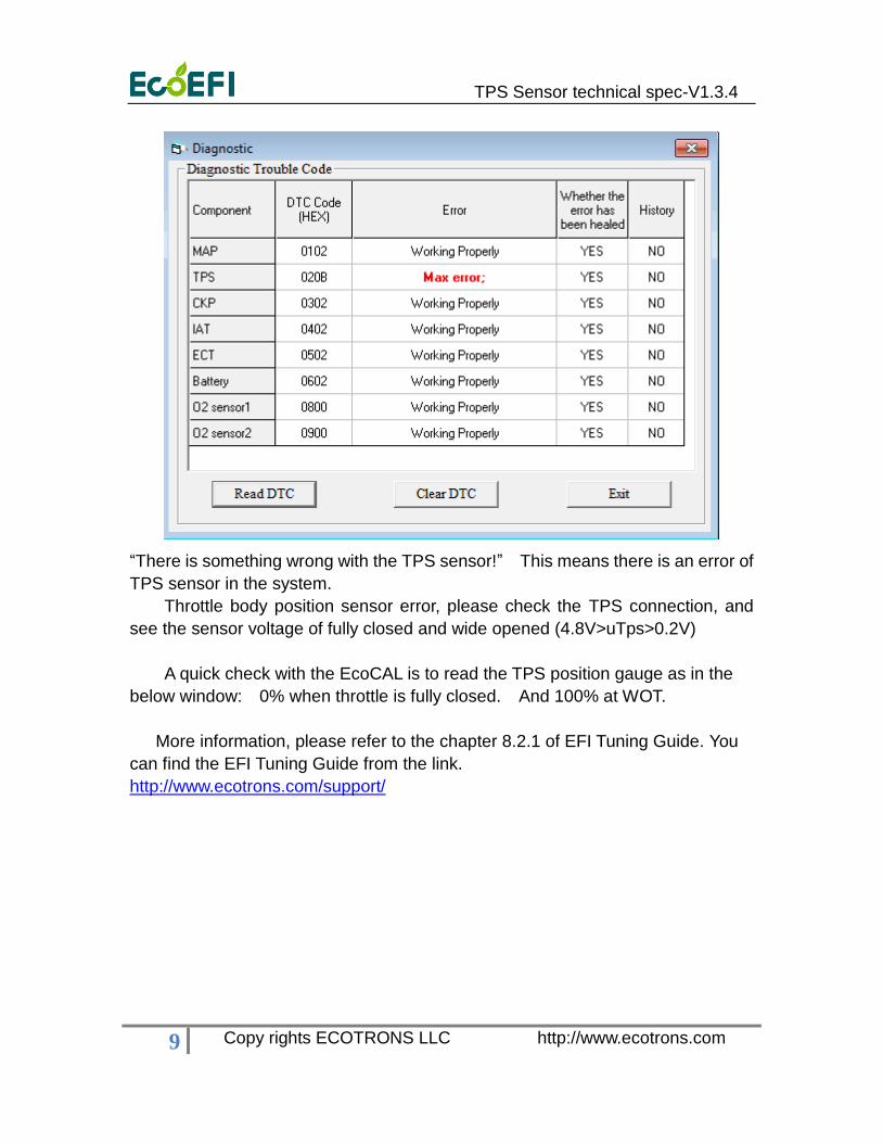
Go to menu->Diagnostic:
TPS Sensor technical spec-V1.3.4
9 Copy rights ECOTRONS LLC http://www.ecotrons.com
“There is something wrong with the TPS sensor!” This means there is an error of
TPS sensor in the system.
Throttle body position sensor error, please check the TPS connection, and
see the sensor voltage of fully closed and wide opened (4.8V>uTps>0.2V)
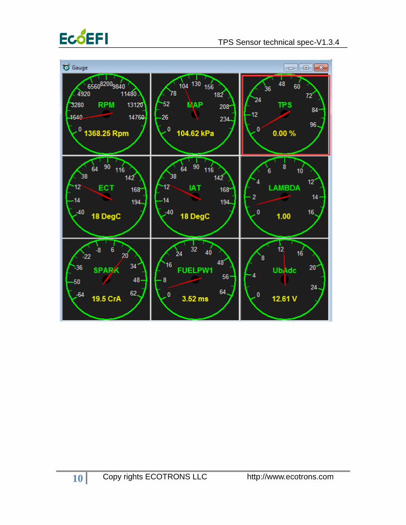
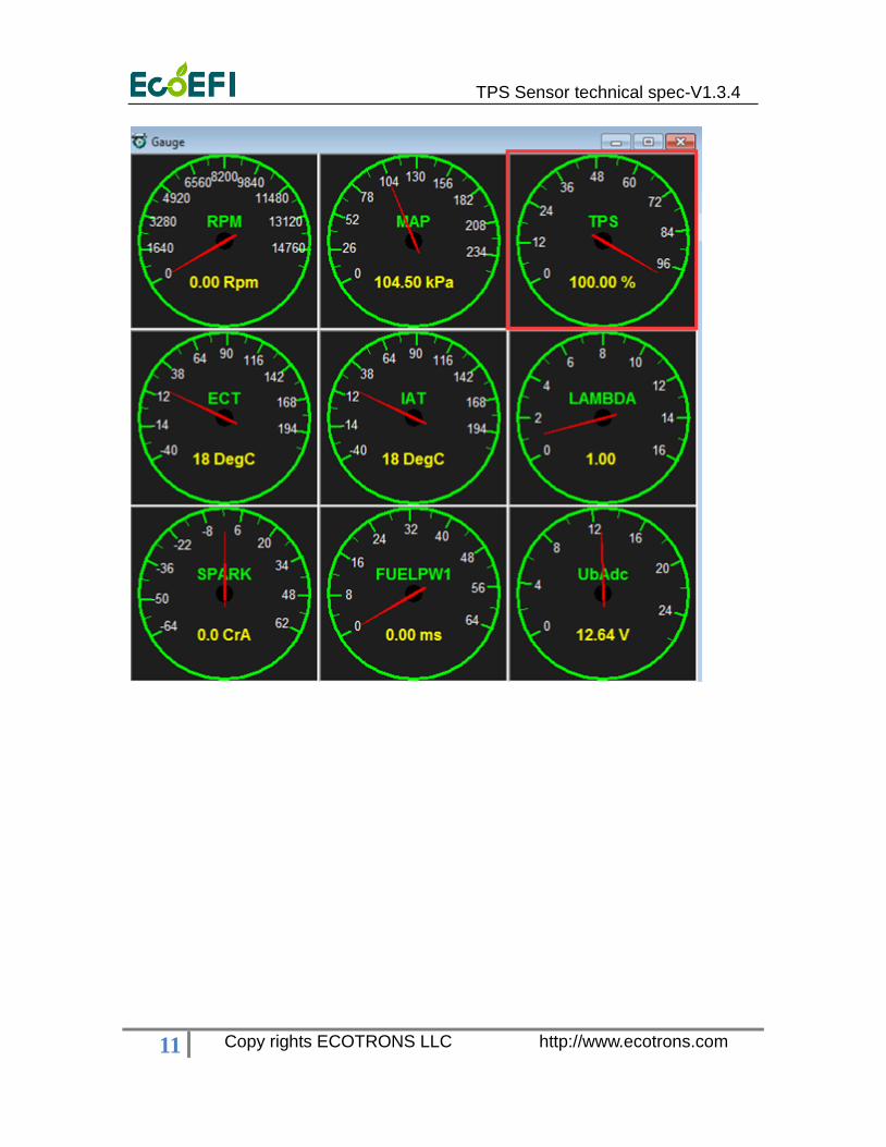
A quick check with the EcoCAL is to read the TPS position gauge as in the
below window: 0% when throttle is fully closed. And 100% at WOT.
More information, please refer to the chapter 8.2.1 of EFI Tuning Guide. You
can find the EFI Tuning Guide from the link.
http://www.ecotrons.com/support/
TPS Sensor technical spec-V1.3.4
10 Copy rights ECOTRONS LLC http://www.ecotrons.com
TPS Sensor technical spec-V1.3.4
11 Copy rights ECOTRONS LLC http://www.ecotrons.com
TPS Sensor technical spec-V1.3.4
12 Copy rights ECOTRONS LLC http://www.ecotrons.com
5 Appendixes: Mechanical CAD Drawing


