They Can Hear Your Heartbeats: Non-Invasive Security forImplantable Medical Devices
Shyamnath Gollakota†
Haitham Hassanieh†
Benjamin Ransford⋆
Dina Katabi†
Kevin Fu⋆
†Massachusetts Institute of Technology
⋆University of Massachusetts, Amherst
{gshyam, haithamh, dk}@mit.edu {ransford, kevinfu}@cs.umass.edu
ABSTRACT
Wireless communication has become an intrinsic part of modernimplantable medical devices (IMDs). Recent work, however, hasdemonstrated that wireless connectivity can be exploited to com-promise the confidentiality of IMDs’ transmitted data or to sendunauthorized commands to IMDs—even commands that cause thedevice to deliver an electric shock to the patient. The key challengein addressing these attacks stems from the difficulty of modifyingor replacing already-implanted IMDs. Thus, in this paper, we ex-plore the feasibility of protecting an implantable device from suchattacks without modifying the device itself. We present a physical-layer solution that delegates the security of an IMD to a personalbase station called the shield. The shield uses a novel radio designthat can act as a jammer-cum-receiver. This design allows it to jamthe IMD’s messages, preventing others from decoding them whilebeing able to decode them itself. It also allows the shield to jamunauthorized commands—even those that try to alter the shield’sown transmissions. We implement our design in a software radioand evaluate it with commercial IMDs. We find that it effectivelyprovides confidentiality for private data and protects the IMD fromunauthorized commands.
Categories and Subject Descriptors C.2.2 [Computer
Systems Organization]: Computer-Communications Networks
General Terms Algorithms, Design, Performance, Security
Keywords Full-duplex, Implanted Medical Devices, Wireless
1. INTRODUCTIONThe past few years have produced innovative health-oriented net-
working and wireless communication technologies, ranging fromlow-power medical radios that harvest body energy [27] to wirelesssensor networks for in-home monitoring and diagnosis [51, 55]. To-day, such wireless systems have become an intrinsic part of manymodern medical devices [39]. In particular, implantable medicaldevices (IMDs), including pacemakers, cardiac defibrillators, in-sulin pumps, and neurostimulators all feature wireless communica-tion [39]. Adding wireless connectivity to IMDs has enabled remote
Permission to make digital or hard copies of all or part of this work forpersonal or classroom use is granted without fee provided that copies arenot made or distributed for profit or commercial advantage and that copiesbear this notice and the full citation on the first page. To copy otherwise, torepublish, to post on servers or to redistribute to lists, requires prior specificpermission and/or a fee.SIGCOMM’11, August 15–19, 2011, Toronto, Ontario, Canada.Copyright 2011 ACM 978-1-4503-0797-0/11/08 ...$10.00.
monitoring of patients’ vital signs and improved care providers’ability to deliver timely treatment, leading to a better health caresystem [31].
Recent work, however, has shown that such wireless connectiv-ity can be exploited to compromise the confidentiality of the IMD’stransmitted data or to send the IMD unauthorized commands—even commands that cause the IMD to deliver an electric shock tothe patient [21, 22]. In other systems, designers use cryptographicmethods to provide confidentiality and prevent unauthorized ac-cess. However, adding cryptography directly to IMDs themselvesis difficult for the following reasons:
• Inalterability: In the U.S. alone, there are millions of people whoalready have wireless IMDs, and about 300,000 such IMDs areimplanted every year [58]. Once implanted, an IMD can last up to10 years [14], and replacing it requires surgery that carries risksof major complications. Incorporating cryptographic mechanimsinto existing IMDs may be infeasible because of limited devicememory and hence can only be achieved by replacing the IMDs.This is not an option for people who have IMDs or may acquirethem in the near future.
• Safety: It is crucial to ensure that health care professionals al-ways have immediate access to an implanted device. However, ifcryptographic methods are embedded in the IMD itself, the de-vice may deny a health care provider access unless she has theright credentials. Yet, credentials might not be available in sce-narios where the patient is at a different hospital, the patient isunconscious, or the cryptographic key storage is damaged or un-reachable [22, 31]. Inability to temporarily adjust or disable anIMD could prove fatal in emergency situations.1
• Maintainability: Software bugs are particularly problematic forIMDs because they can lead to device recalls. In the last eightyears, about 1.5 million software-based medical devices were re-called [15]. Between 1999 and 2005, the number of recalls ofsoftware-based medical devices more than doubled; more than11% of all medical-device recalls during this time period wereattributed to software failures [15]. Such recalls are costly andcould require surgery if the model is already implanted. Thus, itis desirable to limit IMDs’ software to only medically necessaryfunctions.
This paper explores the feasibility of protecting IMDs without
modifying them by implementing security mechanisms entirely onan external device. Such an approach enhances the security of IMDsfor patients who already have them, empowers medical personnelto access a protected IMD by removing the external device or pow-ering it off, and does not in itself increase the risk of IMD recalls.1Note that distributing the credentials widely beyond the patient’s primary health careproviders increases the probability of the key being leaked and presents a major keyrevocation problem.
We present a design in which an external device, called theshield, is interposed between the IMD and potential counter-parties—e.g., worn on the body near an implanted device. Theshield acts as a gateway that relays messages between the IMD andauthorized endpoints. It uses a novel physical-layer mechanism tosecure its communication with the IMD, and it uses a standard cryp-tographic channel to communicate with other authorized endpoints.
The shield counters two classes of adversarial actions: passiveeavesdropping that threatens the confidentiality of the IMD’s trans-missions, and active transmission of unauthorized radio commandsto the IMD. First, to provide confidentiality for the IMD’s trans-missions, the shield continuously listens for those transmissionsand jams them so that they cannot be decoded by eavesdroppers.The shield uses a novel radio design to simultaneously receive theIMD’s signal and transmit a jamming signal. The shield then trans-mits the IMD’s signal to an authorized endpoint using standardcryptographic techniques. Second, to protect the IMD against com-mands from unauthorized endpoints, the shield listens for unautho-rized transmissions addressing the IMD and jams them. As a resultof jamming, the IMD cannot decode the adversarial transmissions,and hence the adversary fails to make the IMD execute an unautho-rized command.
A key challenge that we had to overcome to realize this architec-ture is to design a small wearable radio that simultaneously jamsthe IMD’s signal and receives it. We build on prior work in thearea of full-duplex radio design, which enables a single node totransmit and receive simultaneously [3, 7]. However, prior work re-quires large antenna separation and hence yields large devices un-suitable for our application. In particular, state-of-the-art design forfull-duplex radios [3] exploits the property that a signal reverses itsphase every half a wavelength; it transmits the same signal fromtwo antennas and puts a receive antenna exactly half a wavelengthcloser to one of the transmit antennas than the other. An antennaseparation of half a wavelength, however, is unsuitable for our con-text: the IMDs we consider operate in the 400 MHz band [13] witha wavelength of about 75 cm. A shield that requires the antennas tobe rigidly separated by exactly half a wavelength (37.5 cm) chal-lenges the notion of wearability and therefore patient acceptability.
This paper presents a full-duplex radio that does not impose re-strictions on antenna separation or positioning, and hence can bebuilt as a small wearable device. Our design uses two antennas: ajamming antenna and a receive antenna, placed next to each other.The jamming antenna transmits a random signal to prevent eaves-droppers from decoding the IMD’s transmissions. However, insteadof relying on a particular positioning to cancel the jamming signalat the receive antenna, we connect the receive antenna simultane-ously to both a transmit and a receive chain. We then make thetransmit chain send an antidote signal that cancels the jammingsignal at the receive antenna’s front end, allowing it to receive theIMD’s signal and decode it. We show both analytically and em-pirically that our design delivers its security goals without antennaseparation; hence it can be built as a small wearable radio.
Our design has additional desirable features. Specifically, be-cause the shield can receive while jamming, it can detect adver-saries who try to alter the shield’s signal to convey unauthorizedmessages to the IMD. It can also ensure that it stops jamming themedium when an adversarial signal ends, allowing legitimate de-vices to communicate.
We have implemented a prototype of our design on USRP2 soft-ware radios [9]. We use 400 MHz daughterboards for compatibil-ity with the 402–405 MHz Medical Implant Communication Ser-vices (MICS) band used by IMDs [13]. We evaluate our prototypeshield against two modern IMDs, namely the Medtronic Virtuosoimplantable cardiac defibrillator (ICD) [37] and the Concerto car-
diac resynchronization therapy device (CRT) [36]. Our evaluationreveals the following:
• When the shield is present, it jams the IMD’s messages, causingeven nearby (20 cm away) eavesdroppers to experience a bit errorrate of nearly 50%, which is no better than a random guess.
• When the shield jams the IMD’s packets, it can still reliably de-code them (the packet loss rate is 0.2%, which is negligible). Weconclude that the shield and the IMD share an information chan-nel that is inaccessible to other parties.
• When the shield is absent, the IMD replies to unauthorized com-mands, even if the adversary is in a non-line-of-sight locationmore than 14 m away, and uses a commercial device that oper-ates in the MICS band and adheres to the FCC power limit.
• When the shield is present and has the same transmit power as theadversary, the IMD does not respond to unauthorized commands,even when the adversary is only 20 cm away.
• When the shield is absent and an adversary with 100 times theshield’s power transmits unauthorized commands, the IMD re-sponds from distances as large as 27 m. When the shield ispresent, however, the high-powered adversary’s attempts suc-ceed only from distances less than 5 m, and only in line-of-sight locations. The shield always detects high-powered adver-sarial transmissions and raises an alarm. We conclude that suf-ficiently high-powered adversaries present an intrinsic limita-tion to our physical-layer protection mechanism. However, theshield’s presence reduces the adversary’s success range and in-forms the patient, raising the bar for the adversary’s attempts.
The shield is, to our knowledge, the first system that simultane-ously provides confidentiality for IMDs’ transmissions and protectsIMDs against commands from unauthorized parties without requir-ing any modification to the IMDs themselves. Further, because itaffords physical-layer protection, it may also help provide a com-plementary defense-in-depth solution to devices that feature cryp-tographic or other application-layer protection mechanisms.
Disclaimer. Operating a jamming device has legal implications thatvary by jurisdiction and frequency band. The definition of jammingalso depends on both context and intent. Our experiments were con-ducted in tightly controlled environments where no patients werepresent. Further, the intent of a shield is never to interfere with com-munications that do not involve its protected IMD. We recommendthat anyone considering deployment of technology based on thisresearch consult with their own legal counsel.
2. IMD COMMUNICATION PRIMERWireless communication appears in a wide range of IMDs, in-
cluding those that treat heart failure, diabetes, and Parkinson’s dis-ease. Older models communicated in the 175 KHz band [22]. How-ever, in 1999, the FCC set aside the 402–405 MHz band for medicalimplant communication services (MICS) [13]. The MICS band wasconsidered well suited for IMDs because of its international avail-ability for this purpose [10], its signal propagation characteristicsin the human body, and its range of several meters that allows re-mote monitoring. Modern IMDs communicate medical informationin the MICS band, though devices may use other bands for activa-tion (e.g., 2.4 GHz or 175 KHz) [45]. IMDs share the MICS bandwith meteorological systems on a secondary basis and should en-sure that their usage of it does not interfere with these systems. TheFCC divides the MICS band into multiple channels of 300 KHzwidth [13]. A pair of communicating devices uses one of thesechannels.
IMDs typically communicate infrequently with a device calledan IMD programmer (hereafter, programmer). The programmer ini-
tiates a session with the IMD during which it either queries the IMDfor its data (e.g., patient name, ECG signal) or sends it commands(e.g., a treatment modification). By FCC requirement, the IMD doesnot normally initiate communications; it transmits only in responseto a transmission from a programmer [13] or if it detects a life-threatening condition [23].
A programmer and an IMD share the medium with other de-vices as follows [13]. Before they can use a 300 KHz channel fortheir session, they must “listen” for a minimum of 10 ms to ensurethat the channel is unoccupied. Once they find an unoccupied chan-nel, they establish a session and alternate between the programmertransmitting a query or command, and the IMD responding immedi-ately without sensing the medium [24]. The programmer and IMDcan keep using the channel until the end of their session, or un-til they encounter persistent interference, in which case they listenagain to find an unoccupied channel.
3. ASSUMPTIONS AND THREAT MODEL
3.1 AssumptionsWe assume that IMDs and authorized programmers are honest
and follow the protocols specified by the FCC and their manu-facturers. We also assume the availability of a secure channel fortransmissions between authorized programmers and the shield; thischannel may use the MICS band or other bands. We further assumethat the shield is a wearable device located close to the IMD, such asa necklace. Wearable medical devices are common in the medicalindustry [34, 49]. We also assume that the adversary does not phys-ically try to remove the shield or damage it. We assume that legiti-mate messages sent to an IMD have a checksum and that the IMDwill discard any message that fails the checksum test. This latterassumption is satisfied by all wireless protocols that we are awareof, including the ones used by the IMDs we tested (§9). Finally,we assume that the IMD does not normally initiate transmissions(in accordance with FCC rules [13]); if the IMD initiates a trans-mission because it detects a life-threatening condition, we make noattempt to protect the confidentiality of that transmission.
3.2 Threat ModelWe address two classes of commonly considered radio-equipped
adversaries: passive eavesdroppers that threaten the confidentialityof the IMD’s transmissions, and active adversaries that attempt tosend unauthorized radio commands to the IMD [15, 32].
(a) Passive eavesdropper: Such an adversary eavesdrops on thewireless medium and listens for an IMD’s transmissions. Specifi-cally, we consider an adversary with the following properties:
• The adversary may try different decoding strategies. It may con-sider the jamming signal as noise and try to decode in the pres-ence of jamming. Alternatively, it can implement interferencecancellation or joint decoding in an attempt to simultaneously de-code the jamming signal and the IMD’s transmission. However,basic results in multi-user information theory show that decod-ing multiple signals is impossible if the total information rate isoutside the capacity region [53]. We ensure that the informationrate at the eavesdropper exceeds the capacity region by makingthe shield jam at an excessively high rate; the jamming signal israndom and sent without modulation or coding.
• The adversary may use standard or custom-built equipment. Itmay also use MIMO systems and directional antennas to try toseparate the jamming signal from the IMD’s signal. MIMO anddirectional antenna techniques, however, require the two trans-mitters to be separated by more than half a wavelength (see
Chapter 1 in [26] and Chapter 7 in [53]). The IMDs we con-sider operate in the 400 MHz band with a wavelength of about75 cm. Thus, one can defend against a MIMO eavesdropper oran eavesdropper with a directional antenna by ensuring that theshield is located significantly less than half a wavelength fromthe IMD. For example, if the protected IMD is a pacemaker im-planted near the clavicle, the shield may be implemented as anecklace or a brooch, allowing it to sit within a few centimetersof the IMD.
• The adversary may be in any location farther away from the IMDthan the shield (e.g., at distances 20 cm and greater).
(b) Active adversary: Such an adversary sends unauthorized ra-dio commands to the IMD. These commands may be intended tomodify the IMD’s configuration or to trigger the IMD to transmitunnecessarily, depleting its battery. We allow this adversary the fol-lowing properties:
• The adversary may use one of the following approaches to sendcommands: it may generate its own unauthorized messages; itmay record prior messages from other sources and play themback to the IMD; or it may try to alter an authorized message onthe channel, for example, by transmitting at a higher power andcausing a capture effect at the IMD [46].
• The adversary may use different types of hardware. The adver-sary may transmit with a commercial IMD programmer acquiredfrom a hospital or elsewhere. Such an approach does not requirethe adversary to know the technical specifications of the IMD’scommunication or to reverse-engineer its protocol. However, anadversary that simply uses an unmodified commercial IMD pro-grammer cannot use a transmit power higher than that allowedby the FCC. Alternatively, a more sophisticated adversary mightreverse-engineer the IMD’s communication protocol, then mod-ify the IMD programmer’s hardware or use his own radio trans-mitter to send commands. In this case, the adversary can cus-tomize the hardware to transmit at a higher power than the FCCallows. Further, the adversary may use MIMO or directional an-tennas. Analogous to the above, however, MIMO beamformingand directional antennas require the two receivers to be separatedby a minimum of half a wavelength (37 cm in the MICS band),and hence can be countered by keeping the shield in close prox-imity to the IMD.
• The adversary may be in any location farther away from the IMDthan the shield.
4. SYSTEM OVERVIEWTo achieve our design goal of protecting an IMD without modi-
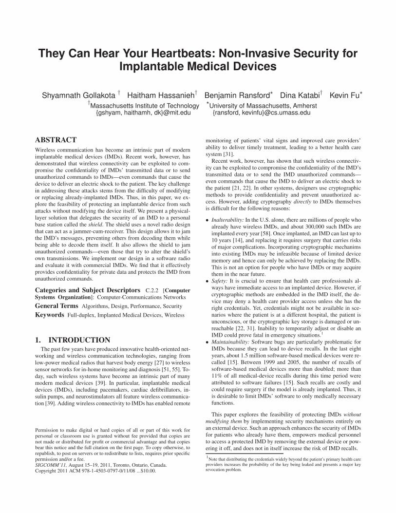
fying it, we design a device called the shield that sits near the IMDand acts as a proxy. An authorized programmer that wants to com-municate with the IMD instead exchanges its messages with theshield, which relays them to the IMD and sends back the IMD’s re-sponses, as shown in Fig. 1. We assume the existence of an authen-ticated, encrypted channel between the shield and the programmer.This channel can be established using either in-band [19] or out-of-band solutions [28].
The shield actively prevents any device other than itself fromcommunicating directly with the IMD. It does so by jamming mes-sages sent to and from the IMD. Key to the shield’s role is its abilityto act as a jammer-cum-receiver, which enables it to jam the IMD’stransmissions and prevent others from decoding them, while stillbeing able to decode them itself. It also enables the shield to de-tect scenarios in which an adversary tries to overpower the shield’sown transmissions to create a capture effect on the IMD and de-liver an unauthorized message. By proxying IMD communications
Encrypted Communication
ProgrammerIMD ShieldEncrypted Communication
Figure 1—Protecting an IMD without modifying it: The shieldjams any direct communication with the IMD. An authorized pro-grammer communicates with the IMD only through the shield, withwhich it establishes a secure channel.
Jamming Signal
Antidote Signal
Baseband to Baseband to Baseband to
ab
nn n
x(t) j(t)
Passband
ADC
Passband
DACDAC
Passband
Shield
sm
it C
ha
in
eiv
e C
ha
in
sm
it C
ha
in
Decoder EncoderEncoder
Tra
n
Re
ce
Tra
n
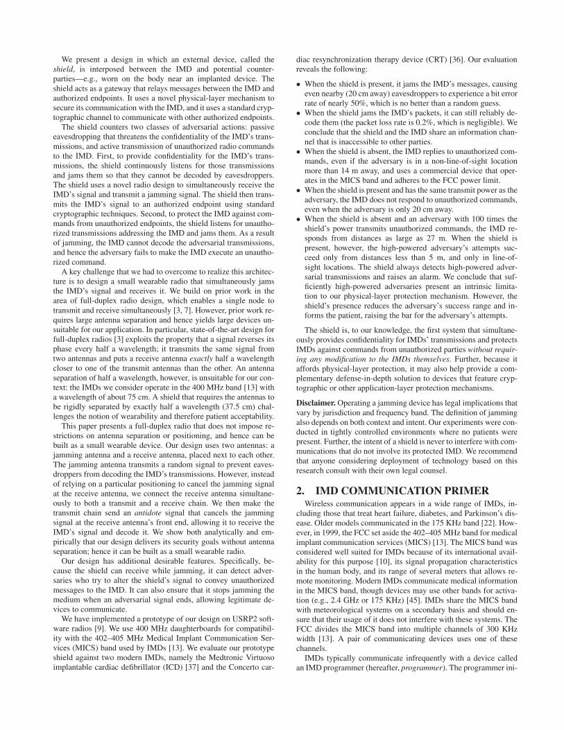
Figure 2—The jammer-cum-receiver design uses two antennas:a jamming antenna that transmits the jamming signal, and a receiveantenna. The receive antenna is connected to both a transmit andreceive chain. The antidote signal is transmitted from the transmitchain to cancel out the jamming signal in the receive chain.
without requiring patients to interact directly with the shield, ourdesign aligns with IMD industry trends toward wireless, time- andlocation-independent patient monitoring.
The next sections explain the jammer-cum-receiver’s design, im-plementation, and use against passive and active adversaries.
5. JAMMER-CUM-RECEIVERA jammer-cum-receiver naturally needs to transmit and receive
simultaneously. This section presents a design for such a full-duplex radio. Our design has two key features: First, it imposes nosize restrictions and hence can be built as a small wearable device.Second, it cancels the jamming signal only at the device’s receiveantenna and at no other point in space—a necessary requirementfor our application.
Our design, shown in Fig. 2, uses two antennas: a jamming an-tenna and a receive antenna. The jamming antenna transmits a ran-dom jamming signal. The receive antenna is simultaneously con-nected to both a transmit and a receive chain. The transmit chainsends an antidote signal that cancels the jamming signal at the re-ceive antenna’s front end, allowing the receive antenna to receiveany signal without disruption from its own jamming signal.
The antidote signal can be computed as follows. Let j(t) be thejamming signal and x(t) be the antidote. Let Hself be the self-looping channel on the receive antenna (i.e., the channel fromthe transmit chain to the receive chain on the same antenna) andHjam→rec the channel from the jamming antenna to the receive an-tenna. The signal received by the shield’s receive antenna is:
y(t) = Hjam→rec j(t) + Hself x(t). (1)
To cancel the jamming signal at the receive antenna, the antidotemust satisfy:
x(t) = −Hjam→rec
Hself
j(t). (2)
Thus, by transmitting a random signal j(t) on its jamming antenna
and an antidote x(t) on its receive antenna, the shield can receivesignals transmitted by other nodes while jamming the medium.
Next, we show that the antidote cancels the jamming signal onlyat the shield’s receive antenna, and no other location. Let Hjam→l
and Hrec→l be the channels from the shield’s jamming and receiveantennas, respectively, to the adversary’s location l. An antenna po-sitioned at l receives the combined signal:
y(t) = Hjam→l j(t) + Hrec→l x(t) (3)
= (Hjam→l − Hrec→l
Hjam→rec
Hself
)j(t). (4)
For the jamming signal to be cancelled out at location l, the follow-ing must be satisfied:
Hjam→l
Hrec→l
=Hjam→rec
Hself
. (5)
Locating the shield’s two antennas very close to each other ensuresthat at any location l the attenuation from the two antennas is com-parable, i.e., |
Hjam→l
Hrec→l| ≈ 1 (see Chapter 7 in [53] for a detailed anal-
ysis). In contrast, |Hjam→rec
Hself| ≪ 1; |Hself | is the attenuation on the
short wire between the transmit and receive chains in the receiveantenna, which is significantly less than the attenuation betweenthe two antennas that additionally have to go on the air [17]. Forexample, in our USRP2 prototype, the ratio |
Hjam→rec
Hself| ≈ −27 dB.
Thus, the above condition is physically infeasible, and cancellingthe jamming signal at the shield’s receive antenna does not cancelit at any other location.
We note several ancillary properties of our design:
• Transmit and receive chains connected to the same antenna: Off-the-shelf radios such as the USRP [9] have both a receive and atransmit chain connected to the same antenna; they can in prin-ciple transmit and receive simultaneously on the same antenna.Traditional systems cannot exploit this property, however, be-cause the transmit signal overpowers the receive chain, prevent-ing the antenna from decoding any signal but its own transmis-sion. When the jamming signal and the antidote signal canceleach other, the interference is cancelled and the antenna can re-ceive from other nodes while transmitting.
• Antenna cancellation vs. analog and digital cancellation: Can-celling the jamming signal with an antidote is a form of an-tenna cancellation. Thus, as in the antenna cancellation schemeby Choi et al. [3], one can improve performance using hardwarecomponents such as analog cancelers [43]. In this case, the inputto the analog canceler will be taken from points a and b in Fig. 2;the output will be fed to the passband filter in the receive chain.
• Channel estimation: Computing the antidote in equation 2 re-quires knowing the channels Hself and Hjam→rec. The shield esti-mates these channels using two methods. First, during a sessionwith the IMD, the shield measures the channels immediately be-fore it transmits to the IMD or jams the IMD’s transmission.In the absence of an IMD session the shield periodically (ev-ery 200 ms in our prototype) estimates this channel by sending aprobe. Since the shield’s two antennas are close to each other, theprobe can be sent at a low power to allow other nodes to leveragespatial reuse to concurrently access the medium.
• Wideband channels: Our discussion has been focused on narrow-band channels. However, the same description can be extendedto work with wideband channels which exhibit multipath effects.Specifically, such channels use OFDM, which divides the band-width into orthogonal subcarriers and treats each of the subcarri-
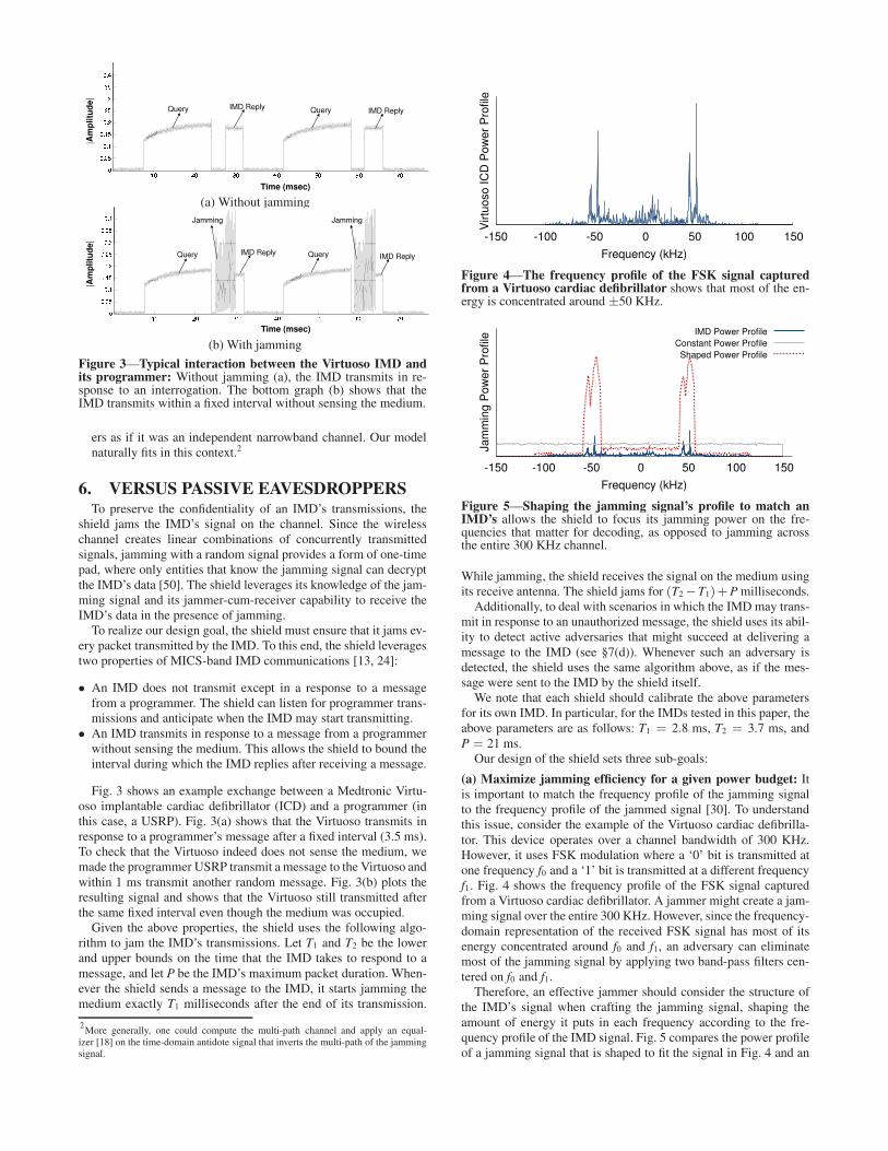
(a) Without jamming
(b) With jamming
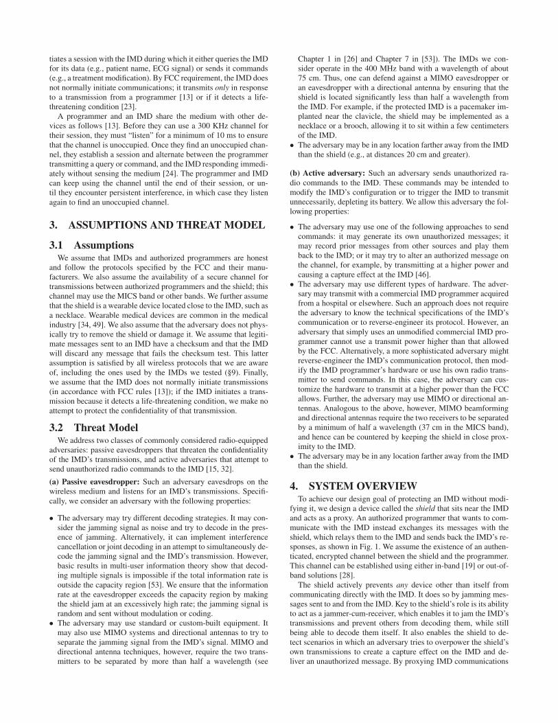
Figure 3—Typical interaction between the Virtuoso IMD andits programmer: Without jamming (a), the IMD transmits in re-sponse to an interrogation. The bottom graph (b) shows that theIMD transmits within a fixed interval without sensing the medium.
ers as if it was an independent narrowband channel. Our modelnaturally fits in this context.2
6. VERSUS PASSIVE EAVESDROPPERSTo preserve the confidentiality of an IMD’s transmissions, the
shield jams the IMD’s signal on the channel. Since the wirelesschannel creates linear combinations of concurrently transmittedsignals, jamming with a random signal provides a form of one-timepad, where only entities that know the jamming signal can decryptthe IMD’s data [50]. The shield leverages its knowledge of the jam-ming signal and its jammer-cum-receiver capability to receive theIMD’s data in the presence of jamming.
To realize our design goal, the shield must ensure that it jams ev-ery packet transmitted by the IMD. To this end, the shield leveragestwo properties of MICS-band IMD communications [13, 24]:
• An IMD does not transmit except in a response to a messagefrom a programmer. The shield can listen for programmer trans-missions and anticipate when the IMD may start transmitting.
• An IMD transmits in response to a message from a programmerwithout sensing the medium. This allows the shield to bound theinterval during which the IMD replies after receiving a message.
Fig. 3 shows an example exchange between a Medtronic Virtu-oso implantable cardiac defibrillator (ICD) and a programmer (inthis case, a USRP). Fig. 3(a) shows that the Virtuoso transmits inresponse to a programmer’s message after a fixed interval (3.5 ms).To check that the Virtuoso indeed does not sense the medium, wemade the programmer USRP transmit a message to the Virtuoso andwithin 1 ms transmit another random message. Fig. 3(b) plots theresulting signal and shows that the Virtuoso still transmitted afterthe same fixed interval even though the medium was occupied.
Given the above properties, the shield uses the following algo-rithm to jam the IMD’s transmissions. Let T1 and T2 be the lowerand upper bounds on the time that the IMD takes to respond to amessage, and let P be the IMD’s maximum packet duration. When-ever the shield sends a message to the IMD, it starts jamming themedium exactly T1 milliseconds after the end of its transmission.
2More generally, one could compute the multi-path channel and apply an equal-izer [18] on the time-domain antidote signal that inverts the multi-path of the jammingsignal.
-150 -100 -50 0 50 100 150
Virtu
oso
IC
D P
ow
er
Pro
file
Frequency (kHz)
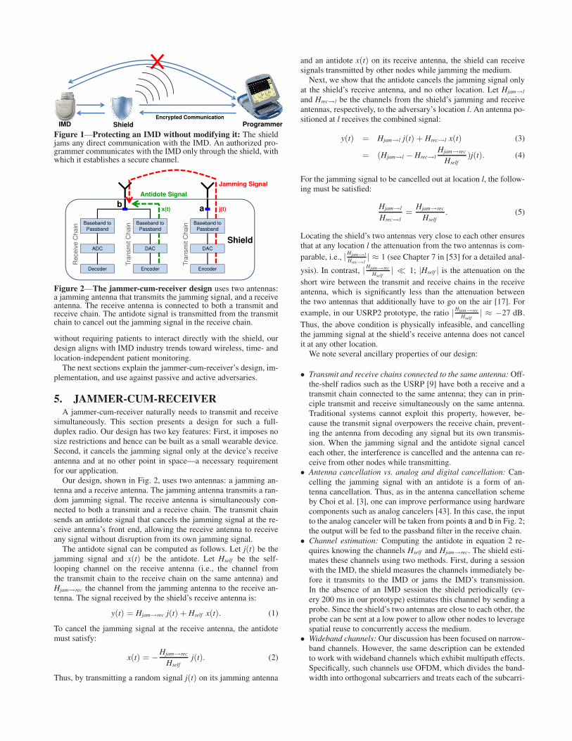
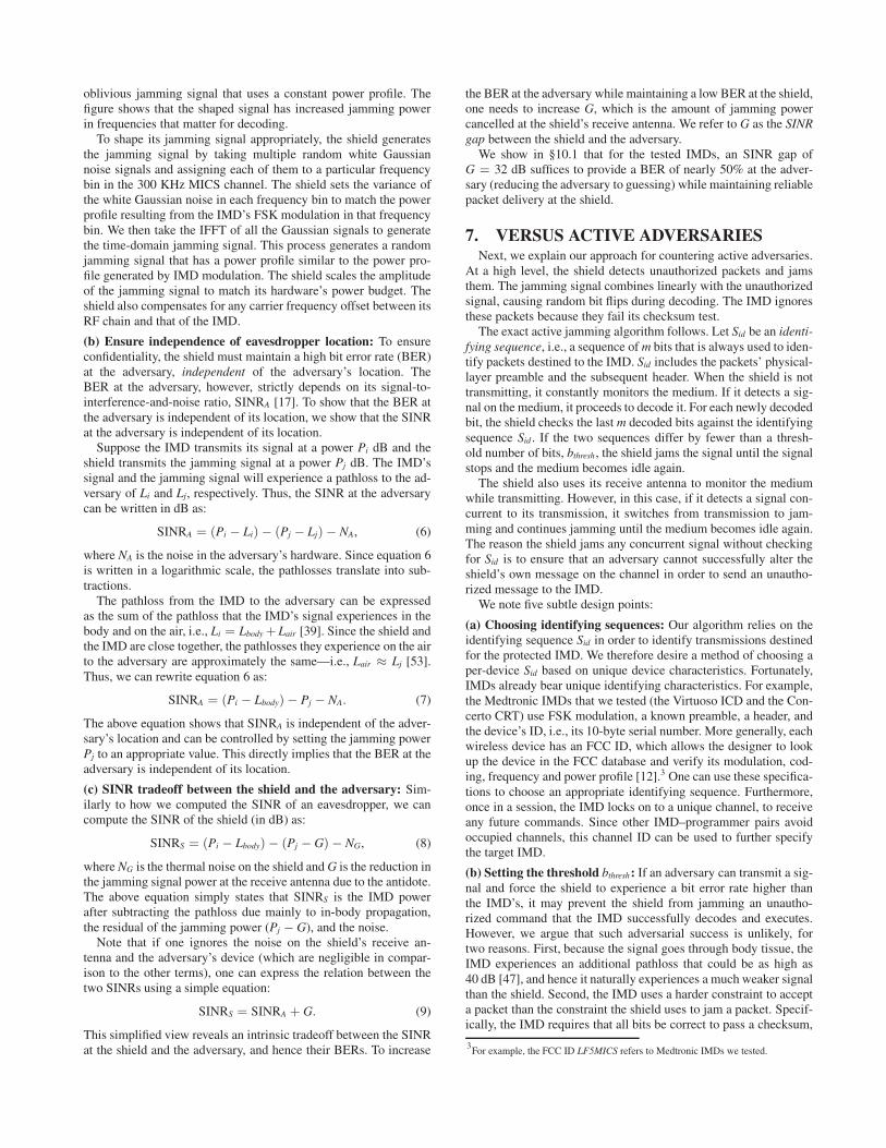
Figure 4—The frequency profile of the FSK signal capturedfrom a Virtuoso cardiac defibrillator shows that most of the en-ergy is concentrated around ±50 KHz.
-150 -100 -50 0 50 100 150
Ja
mm
ing
Po
we
r P
rofile
Frequency (kHz)
IMD Power Profile
Constant Power Profile
Shaped Power Profile
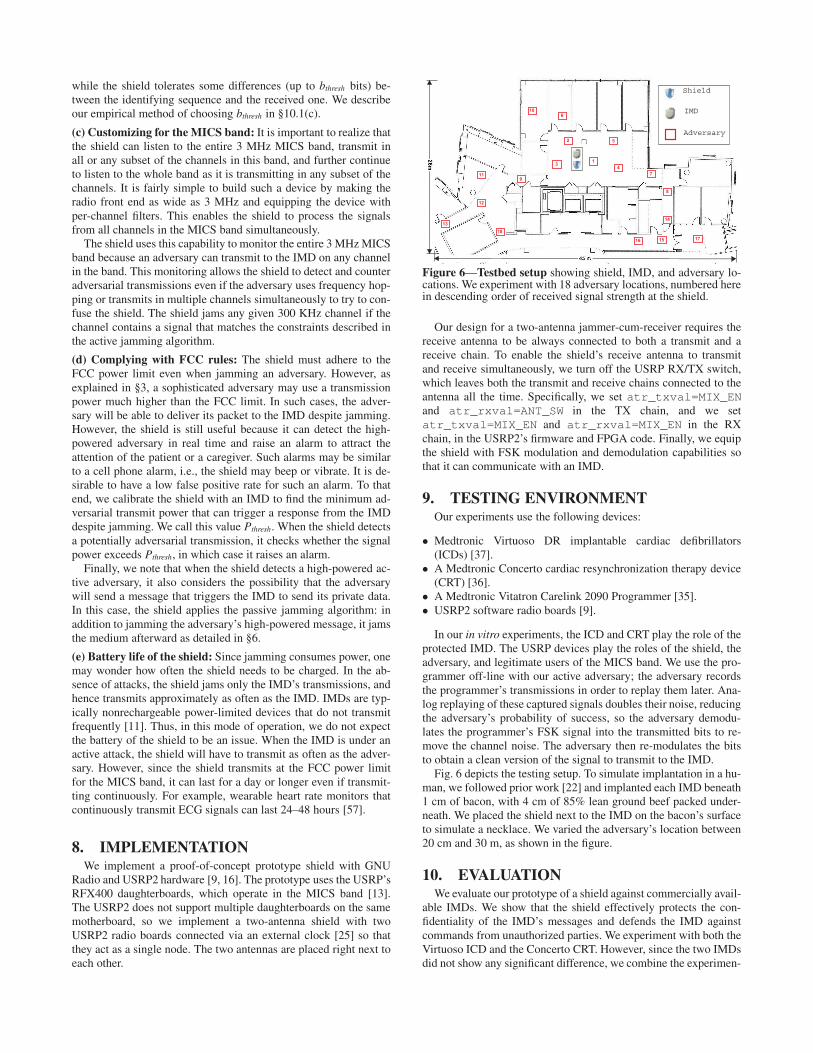
Figure 5—Shaping the jamming signal’s profile to match anIMD’s allows the shield to focus its jamming power on the fre-quencies that matter for decoding, as opposed to jamming acrossthe entire 300 KHz channel.
While jamming, the shield receives the signal on the medium usingits receive antenna. The shield jams for (T2−T1)+Pmilliseconds.
Additionally, to deal with scenarios in which the IMDmay trans-mit in response to an unauthorized message, the shield uses its abil-ity to detect active adversaries that might succeed at delivering amessage to the IMD (see §7(d)). Whenever such an adversary isdetected, the shield uses the same algorithm above, as if the mes-sage were sent to the IMD by the shield itself.
We note that each shield should calibrate the above parametersfor its own IMD. In particular, for the IMDs tested in this paper, theabove parameters are as follows: T1 = 2.8 ms, T2 = 3.7 ms, andP = 21 ms.
Our design of the shield sets three sub-goals:
(a) Maximize jamming efficiency for a given power budget: Itis important to match the frequency profile of the jamming signalto the frequency profile of the jammed signal [30]. To understandthis issue, consider the example of the Virtuoso cardiac defibrilla-tor. This device operates over a channel bandwidth of 300 KHz.However, it uses FSK modulation where a ‘0’ bit is transmitted atone frequency f0 and a ‘1’ bit is transmitted at a different frequencyf1. Fig. 4 shows the frequency profile of the FSK signal capturedfrom a Virtuoso cardiac defibrillator. A jammer might create a jam-ming signal over the entire 300 KHz. However, since the frequency-domain representation of the received FSK signal has most of itsenergy concentrated around f0 and f1, an adversary can eliminatemost of the jamming signal by applying two band-pass filters cen-tered on f0 and f1.
Therefore, an effective jammer should consider the structure ofthe IMD’s signal when crafting the jamming signal, shaping theamount of energy it puts in each frequency according to the fre-quency profile of the IMD signal. Fig. 5 compares the power profileof a jamming signal that is shaped to fit the signal in Fig. 4 and an
oblivious jamming signal that uses a constant power profile. Thefigure shows that the shaped signal has increased jamming powerin frequencies that matter for decoding.
To shape its jamming signal appropriately, the shield generatesthe jamming signal by taking multiple random white Gaussiannoise signals and assigning each of them to a particular frequencybin in the 300 KHz MICS channel. The shield sets the variance ofthe white Gaussian noise in each frequency bin to match the powerprofile resulting from the IMD’s FSK modulation in that frequencybin. We then take the IFFT of all the Gaussian signals to generatethe time-domain jamming signal. This process generates a randomjamming signal that has a power profile similar to the power pro-file generated by IMD modulation. The shield scales the amplitudeof the jamming signal to match its hardware’s power budget. Theshield also compensates for any carrier frequency offset between itsRF chain and that of the IMD.
(b) Ensure independence of eavesdropper location: To ensureconfidentiality, the shield must maintain a high bit error rate (BER)at the adversary, independent of the adversary’s location. TheBER at the adversary, however, strictly depends on its signal-to-interference-and-noise ratio, SINRA [17]. To show that the BER atthe adversary is independent of its location, we show that the SINRat the adversary is independent of its location.
Suppose the IMD transmits its signal at a power Pi dB and theshield transmits the jamming signal at a power Pj dB. The IMD’ssignal and the jamming signal will experience a pathloss to the ad-versary of Li and Lj, respectively. Thus, the SINR at the adversarycan be written in dB as:
SINRA = (Pi − Li) − (Pj − Lj) − NA, (6)
where NA is the noise in the adversary’s hardware. Since equation 6is written in a logarithmic scale, the pathlosses translate into sub-tractions.
The pathloss from the IMD to the adversary can be expressedas the sum of the pathloss that the IMD’s signal experiences in thebody and on the air, i.e., Li = Lbody +Lair [39]. Since the shield andthe IMD are close together, the pathlosses they experience on the airto the adversary are approximately the same—i.e., Lair ≈ Lj [53].Thus, we can rewrite equation 6 as:
SINRA = (Pi − Lbody) − Pj − NA. (7)
The above equation shows that SINRA is independent of the adver-sary’s location and can be controlled by setting the jamming powerPj to an appropriate value. This directly implies that the BER at theadversary is independent of its location.
(c) SINR tradeoff between the shield and the adversary: Sim-ilarly to how we computed the SINR of an eavesdropper, we cancompute the SINR of the shield (in dB) as:
SINRS = (Pi − Lbody) − (Pj − G) − NG, (8)
where NG is the thermal noise on the shield andG is the reduction inthe jamming signal power at the receive antenna due to the antidote.The above equation simply states that SINRS is the IMD powerafter subtracting the pathloss due mainly to in-body propagation,the residual of the jamming power (Pj − G), and the noise.
Note that if one ignores the noise on the shield’s receive an-tenna and the adversary’s device (which are negligible in compar-ison to the other terms), one can express the relation between thetwo SINRs using a simple equation:
SINRS = SINRA + G. (9)
This simplified view reveals an intrinsic tradeoff between the SINRat the shield and the adversary, and hence their BERs. To increase
the BER at the adversary while maintaining a low BER at the shield,one needs to increase G, which is the amount of jamming powercancelled at the shield’s receive antenna. We refer to G as the SINRgap between the shield and the adversary.
We show in §10.1 that for the tested IMDs, an SINR gap ofG = 32 dB suffices to provide a BER of nearly 50% at the adver-sary (reducing the adversary to guessing) while maintaining reliablepacket delivery at the shield.
7. VERSUS ACTIVE ADVERSARIESNext, we explain our approach for countering active adversaries.
At a high level, the shield detects unauthorized packets and jamsthem. The jamming signal combines linearly with the unauthorizedsignal, causing random bit flips during decoding. The IMD ignoresthese packets because they fail its checksum test.
The exact active jamming algorithm follows. Let Sid be an identi-fying sequence, i.e., a sequence ofm bits that is always used to iden-tify packets destined to the IMD. Sid includes the packets’ physical-layer preamble and the subsequent header. When the shield is nottransmitting, it constantly monitors the medium. If it detects a sig-nal on the medium, it proceeds to decode it. For each newly decodedbit, the shield checks the last m decoded bits against the identifyingsequence Sid . If the two sequences differ by fewer than a thresh-old number of bits, bthresh, the shield jams the signal until the signalstops and the medium becomes idle again.
The shield also uses its receive antenna to monitor the mediumwhile transmitting. However, in this case, if it detects a signal con-current to its transmission, it switches from transmission to jam-ming and continues jamming until the medium becomes idle again.The reason the shield jams any concurrent signal without checkingfor Sid is to ensure that an adversary cannot successfully alter theshield’s own message on the channel in order to send an unautho-rized message to the IMD.
We note five subtle design points:
(a) Choosing identifying sequences: Our algorithm relies on theidentifying sequence Sid in order to identify transmissions destinedfor the protected IMD. We therefore desire a method of choosing aper-device Sid based on unique device characteristics. Fortunately,IMDs already bear unique identifying characteristics. For example,the Medtronic IMDs that we tested (the Virtuoso ICD and the Con-certo CRT) use FSK modulation, a known preamble, a header, andthe device’s ID, i.e., its 10-byte serial number. More generally, eachwireless device has an FCC ID, which allows the designer to lookup the device in the FCC database and verify its modulation, cod-ing, frequency and power profile [12].3 One can use these specifica-tions to choose an appropriate identifying sequence. Furthermore,once in a session, the IMD locks on to a unique channel, to receiveany future commands. Since other IMD–programmer pairs avoidoccupied channels, this channel ID can be used to further specifythe target IMD.
(b) Setting the threshold bthresh: If an adversary can transmit a sig-nal and force the shield to experience a bit error rate higher thanthe IMD’s, it may prevent the shield from jamming an unautho-rized command that the IMD successfully decodes and executes.However, we argue that such adversarial success is unlikely, fortwo reasons. First, because the signal goes through body tissue, theIMD experiences an additional pathloss that could be as high as40 dB [47], and hence it naturally experiences a much weaker signalthan the shield. Second, the IMD uses a harder constraint to accepta packet than the constraint the shield uses to jam a packet. Specif-ically, the IMD requires that all bits be correct to pass a checksum,
3For example, the FCC ID LF5MICS refers to Medtronic IMDs we tested.
while the shield tolerates some differences (up to bthresh bits) be-tween the identifying sequence and the received one. We describeour empirical method of choosing bthresh in §10.1(c).
(c) Customizing for the MICS band: It is important to realize thatthe shield can listen to the entire 3 MHz MICS band, transmit inall or any subset of the channels in this band, and further continueto listen to the whole band as it is transmitting in any subset of thechannels. It is fairly simple to build such a device by making theradio front end as wide as 3 MHz and equipping the device withper-channel filters. This enables the shield to process the signalsfrom all channels in the MICS band simultaneously.
The shield uses this capability to monitor the entire 3 MHzMICSband because an adversary can transmit to the IMD on any channelin the band. This monitoring allows the shield to detect and counteradversarial transmissions even if the adversary uses frequency hop-ping or transmits in multiple channels simultaneously to try to con-fuse the shield. The shield jams any given 300 KHz channel if thechannel contains a signal that matches the constraints described inthe active jamming algorithm.
(d) Complying with FCC rules: The shield must adhere to theFCC power limit even when jamming an adversary. However, asexplained in §3, a sophisticated adversary may use a transmissionpower much higher than the FCC limit. In such cases, the adver-sary will be able to deliver its packet to the IMD despite jamming.However, the shield is still useful because it can detect the high-powered adversary in real time and raise an alarm to attract theattention of the patient or a caregiver. Such alarms may be similarto a cell phone alarm, i.e., the shield may beep or vibrate. It is de-sirable to have a low false positive rate for such an alarm. To thatend, we calibrate the shield with an IMD to find the minimum ad-versarial transmit power that can trigger a response from the IMDdespite jamming. We call this value Pthresh. When the shield detectsa potentially adversarial transmission, it checks whether the signalpower exceeds Pthresh, in which case it raises an alarm.
Finally, we note that when the shield detects a high-powered ac-tive adversary, it also considers the possibility that the adversarywill send a message that triggers the IMD to send its private data.In this case, the shield applies the passive jamming algorithm: inaddition to jamming the adversary’s high-powered message, it jamsthe medium afterward as detailed in §6.
(e) Battery life of the shield: Since jamming consumes power, onemay wonder how often the shield needs to be charged. In the ab-sence of attacks, the shield jams only the IMD’s transmissions, andhence transmits approximately as often as the IMD. IMDs are typ-ically nonrechargeable power-limited devices that do not transmitfrequently [11]. Thus, in this mode of operation, we do not expectthe battery of the shield to be an issue. When the IMD is under anactive attack, the shield will have to transmit as often as the adver-sary. However, since the shield transmits at the FCC power limitfor the MICS band, it can last for a day or longer even if transmit-ting continuously. For example, wearable heart rate monitors thatcontinuously transmit ECG signals can last 24–48 hours [57].
8. IMPLEMENTATIONWe implement a proof-of-concept prototype shield with GNU
Radio and USRP2 hardware [9, 16]. The prototype uses the USRP’sRFX400 daughterboards, which operate in the MICS band [13].The USRP2 does not support multiple daughterboards on the samemotherboard, so we implement a two-antenna shield with twoUSRP2 radio boards connected via an external clock [25] so thatthey act as a single node. The two antennas are placed right next toeach other.
4
1
2
3
6
5
7
8
14
16 15 17
911
12
13
18
Shield
IMD
Adversary
10
8.92 in
6.92in
8.8.8.8.8.929999 inininnn
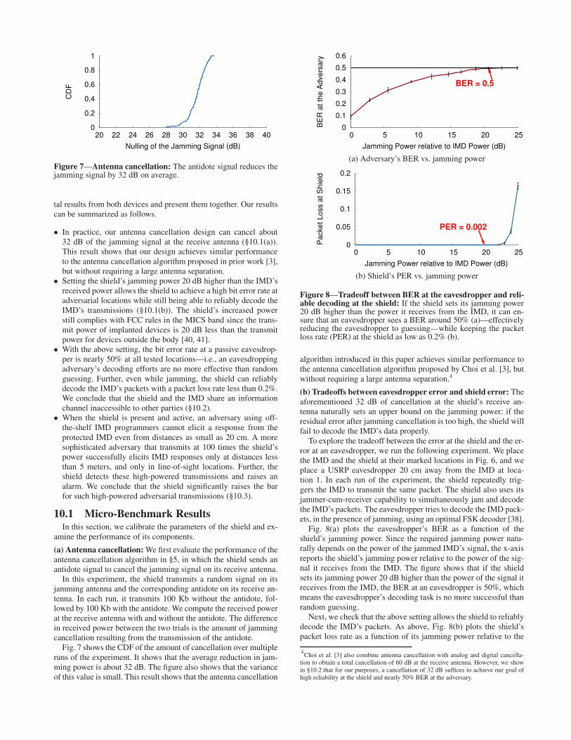
Figure 6—Testbed setup showing shield, IMD, and adversary lo-cations. We experiment with 18 adversary locations, numbered herein descending order of received signal strength at the shield.
Our design for a two-antenna jammer-cum-receiver requires thereceive antenna to be always connected to both a transmit and areceive chain. To enable the shield’s receive antenna to transmitand receive simultaneously, we turn off the USRP RX/TX switch,which leaves both the transmit and receive chains connected to theantenna all the time. Specifically, we set atr_txval=MIX_ENand atr_rxval=ANT_SW in the TX chain, and we setatr_txval=MIX_EN and atr_rxval=MIX_EN in the RXchain, in the USRP2’s firmware and FPGA code. Finally, we equipthe shield with FSK modulation and demodulation capabilities sothat it can communicate with an IMD.
9. TESTING ENVIRONMENTOur experiments use the following devices:
• Medtronic Virtuoso DR implantable cardiac defibrillators(ICDs) [37].
• A Medtronic Concerto cardiac resynchronization therapy device(CRT) [36].
• AMedtronic Vitatron Carelink 2090 Programmer [35].• USRP2 software radio boards [9].
In our in vitro experiments, the ICD and CRT play the role of theprotected IMD. The USRP devices play the roles of the shield, theadversary, and legitimate users of the MICS band. We use the pro-grammer off-line with our active adversary; the adversary recordsthe programmer’s transmissions in order to replay them later. Ana-log replaying of these captured signals doubles their noise, reducingthe adversary’s probability of success, so the adversary demodu-lates the programmer’s FSK signal into the transmitted bits to re-move the channel noise. The adversary then re-modulates the bitsto obtain a clean version of the signal to transmit to the IMD.
Fig. 6 depicts the testing setup. To simulate implantation in a hu-man, we followed prior work [22] and implanted each IMD beneath1 cm of bacon, with 4 cm of 85% lean ground beef packed under-neath. We placed the shield next to the IMD on the bacon’s surfaceto simulate a necklace. We varied the adversary’s location between20 cm and 30 m, as shown in the figure.
10. EVALUATIONWe evaluate our prototype of a shield against commercially avail-
able IMDs. We show that the shield effectively protects the con-fidentiality of the IMD’s messages and defends the IMD againstcommands from unauthorized parties. We experiment with both theVirtuoso ICD and the Concerto CRT. However, since the two IMDsdid not show any significant difference, we combine the experimen-
0
0.2
0.4
0.6
0.8
1
20 22 24 26 28 30 32 34 36 38 40
CD
F
Nulling of the Jamming Signal (dB)
Figure 7—Antenna cancellation: The antidote signal reduces thejamming signal by 32 dB on average.
tal results from both devices and present them together. Our resultscan be summarized as follows.
• In practice, our antenna cancellation design can cancel about32 dB of the jamming signal at the receive antenna (§10.1(a)).This result shows that our design achieves similar performanceto the antenna cancellation algorithm proposed in prior work [3],but without requiring a large antenna separation.
• Setting the shield’s jamming power 20 dB higher than the IMD’sreceived power allows the shield to achieve a high bit error rate atadversarial locations while still being able to reliably decode theIMD’s transmissions (§10.1(b)). The shield’s increased powerstill complies with FCC rules in the MICS band since the trans-mit power of implanted devices is 20 dB less than the transmitpower for devices outside the body [40, 41].
• With the above setting, the bit error rate at a passive eavesdrop-per is nearly 50% at all tested locations—i.e., an eavesdroppingadversary’s decoding efforts are no more effective than randomguessing. Further, even while jamming, the shield can reliablydecode the IMD’s packets with a packet loss rate less than 0.2%.We conclude that the shield and the IMD share an informationchannel inaccessible to other parties (§10.2).
• When the shield is present and active, an adversary using off-the-shelf IMD programmers cannot elicit a response from theprotected IMD even from distances as small as 20 cm. A moresophisticated adversary that transmits at 100 times the shield’spower successfully elicits IMD responses only at distances lessthan 5 meters, and only in line-of-sight locations. Further, theshield detects these high-powered transmissions and raises analarm. We conclude that the shield significantly raises the barfor such high-powered adversarial transmissions (§10.3).
10.1 Micro-Benchmark ResultsIn this section, we calibrate the parameters of the shield and ex-
amine the performance of its components.
(a) Antenna cancellation:We first evaluate the performance of theantenna cancellation algorithm in §5, in which the shield sends anantidote signal to cancel the jamming signal on its receive antenna.
In this experiment, the shield transmits a random signal on itsjamming antenna and the corresponding antidote on its receive an-tenna. In each run, it transmits 100 Kb without the antidote, fol-lowed by 100 Kb with the antidote. We compute the received powerat the receive antenna with and without the antidote. The differencein received power between the two trials is the amount of jammingcancellation resulting from the transmission of the antidote.
Fig. 7 shows the CDF of the amount of cancellation over multipleruns of the experiment. It shows that the average reduction in jam-ming power is about 32 dB. The figure also shows that the varianceof this value is small. This result shows that the antenna cancellation
0
0.1
0.2
0.3
0.4
0.5
0.6
0 5 10 15 20 25
BE
R a
t th
e A
dve
rsa
ry
Jamming Power relative to IMD Power (dB)
BER = 0.5
(a) Adversary’s BER vs. jamming power
0
0.05
0.1
0.15
0.2
0 5 10 15 20 25
Pa
cke
t L
oss a
t S
hie
ld
Jamming Power relative to IMD Power (dB)
PER = 0.002
(b) Shield’s PER vs. jamming power
Figure 8—Tradeoff between BER at the eavesdropper and reli-able decoding at the shield: If the shield sets its jamming power20 dB higher than the power it receives from the IMD, it can en-sure that an eavesdropper sees a BER around 50% (a)—effectivelyreducing the eavesdropper to guessing—while keeping the packetloss rate (PER) at the shield as low as 0.2% (b).
algorithm introduced in this paper achieves similar performance tothe antenna cancellation algorithm proposed by Choi et al. [3], butwithout requiring a large antenna separation.4
(b) Tradeoffs between eavesdropper error and shield error: Theaforementioned 32 dB of cancellation at the shield’s receive an-tenna naturally sets an upper bound on the jamming power: if theresidual error after jamming cancellation is too high, the shield willfail to decode the IMD’s data properly.
To explore the tradeoff between the error at the shield and the er-ror at an eavesdropper, we run the following experiment. We placethe IMD and the shield at their marked locations in Fig. 6, and weplace a USRP eavesdropper 20 cm away from the IMD at loca-tion 1. In each run of the experiment, the shield repeatedly trig-gers the IMD to transmit the same packet. The shield also uses itsjammer-cum-receiver capability to simultaneously jam and decodethe IMD’s packets. The eavesdropper tries to decode the IMD pack-ets, in the presence of jamming, using an optimal FSK decoder [38].
Fig. 8(a) plots the eavesdropper’s BER as a function of theshield’s jamming power. Since the required jamming power natu-rally depends on the power of the jammed IMD’s signal, the x-axisreports the shield’s jamming power relative to the power of the sig-nal it receives from the IMD. The figure shows that if the shieldsets its jamming power 20 dB higher than the power of the signal itreceives from the IMD, the BER at an eavesdropper is 50%, whichmeans the eavesdropper’s decoding task is no more successful thanrandom guessing.
Next, we check that the above setting allows the shield to reliablydecode the IMD’s packets. As above, Fig. 8(b) plots the shield’spacket loss rate as a function of its jamming power relative to the
4Choi et al. [3] also combine antenna cancellation with analog and digital cancella-tion to obtain a total cancellation of 60 dB at the receive antenna. However, we showin §10.2 that for our purposes, a cancellation of 32 dB suffices to achieve our goal ofhigh reliability at the shield and nearly 50% BER at the adversary.
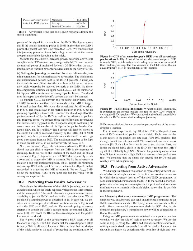
Pthresh: Adversary power Minimum −11.1 dBmthat elicits IMD response Average −4.5 dBm
Standard Deviation 3.5 dBm
Table 1—Adversarial RSSI that elicits IMD responses despite theshield’s jamming.
power of the signal it receives from the IMD. The figure showsthat if the shield’s jamming power is 20 dB higher than the IMD’spower, the packet loss rate is no more than 0.2%. We conclude thatthis jamming power achieves both a high error rate at the eaves-dropper and reliable decoding at the shield.
We note that the shield’s increased power, described above, stillcomplies with FCC rules on power usage in the MICS band becausethe transmit power of implanted devices is 20 dB less than the max-imum allowed transmit power for devices outside the body [40, 41].
(c) Setting the jamming parameters: Next we calibrate the jam-ming parameters for countering active adversaries. The shield mustjam unauthorized packets sent to the IMD it protects. It must jamthese packets even if it receives them with some bit errors, becausethey might otherwise be received correctly at the IMD. We there-fore empirically estimate an upper bound, bthresh , on the number ofbit flips an IMD accepts in an adversary’s packet header. The shielduses this upper bound to identify packets that must be jammed.
To estimate bthresh, we perform the following experiment. First,a USRP transmits unauthorized commands to the IMD to triggerit to send patient data. We repeat the experiment for all locationsin Fig. 6. The shield stays in its marked location in Fig. 6, but itsjamming capability is turned off. However, the shield logs all of thepackets transmitted by the IMD as well as the adversarial packetsthat triggered them. We process these logs offline and, for packetsthat successfully triggered an IMD response despite containing biterrors, we count the number of bit flips in the packet header. Ourresults show that it is unlikely that a packet will have bit errors atthe shield but still be received correctly by the IMD. Out of 5000packets, only three packets showed errors at the shield but still trig-gered a response from an IMD. The maximum number of bit flipsin those packets was 2, so we conservatively set bthresh = 4.
Next, we measure Pthresh, the minimum adversary RSSI at theshield that can elicit a response from the IMD in the presence ofjamming. To do so, we fix the location of the IMD and the shieldas shown in Fig. 6. Again we use a USRP that repeatedly sendsa command to trigger the IMD to transmit. We fix the adversary inlocation 1 and vary its transmit power. Table 1 reports the minimumand average RSSI at the shield’s receive antenna for all packets thatsucceeded in triggering the IMD to transmit. We set Pthresh 3 dBbelow the minimum RSSI in the table and use that value for allsubsequent experiments.
10.2 Protecting from Passive AdversariesTo evaluate the effectiveness of the shield’s jamming, we run an
experiment in which the shield repeatedly triggers the IMD to trans-mit the same packet. The shield also uses its jammer-cum-receivercapability to jam the IMD’s packets while it decodes them. We setthe shield’s jamming power as described in §6. In each run, we po-sition an eavesdropper at a different location shown in Fig. 6 andmake the IMD send 1000 packets. The eavesdropping adversaryattempts to decode the IMD’s packets using an optimal FSK de-coder [38]. We record the BER at the eavesdropper and the packetloss rate at the shield.
Fig. 9 plots a CDF of the eavesdropper’s BER taken over alllocations in Fig. 6. The CDF shows that the eavesdropper’s BERis nearly 50% in all tested locations. We conclude that our designof the shield achieves the goal of protecting the confidentiality of
0
0.2
0.4
0.6
0.8
1
0 0.1 0.2 0.3 0.4 0.5 0.6 0.7 0.8 0.9 1
CD
F
BER at the Adversary
Figure 9—CDF of an eavesdropper’s BER over all eavesdrop-per locations in Fig. 6: At all locations, the eavesdropper’s BERis nearly 50%, which makes its decoding task no more successfulthan random guessing. The low variance in the CDF shows that aneavesdropper’s BER is independent of its location.
0
0.2
0.4
0.6
0.8
1
0 0.005 0.01 0.015 0.02 0.025
CD
FPacket Loss at the Shield
Figure 10—Packet loss at the shield:When the shield is jamming,it experiences an average packet loss rate of only 0.2% when re-ceiving the IMD’s packets. We conclude that the shield can reliablydecode the IMD’s transmissions despite jamming.
IMD’s transmissions from an eavesdropper regardless of the eaves-dropper’s location.
For the same experiment, Fig. 10 plots a CDF of the packet lossrate of IMD-transmitted packets at the shield. Each point on thex-axis refers to the packet loss rate over 1000 IMD packets. Theaverage packet loss rate is about 0.2%, considered low for wirelesssystems [8]. Such a low loss rate is due to two factors. First, welocate the shield fairly close to the IMD, so it receives the IMD’ssignal at a relatively high SNR. Second, the jamming cancellationis sufficient to maintain a high SNR that ensures a low packet lossrate. We conclude that the shield can decode the IMD’s packetsreliably, even while jamming.
10.3 Protecting from Active AdversariesWe distinguish between two scenarios representing different lev-
els of adversarial sophistication. In the first, we consider scenariosin which the adversary uses an off-the-shelf IMD programmer tosend unauthorized commands to the IMD. In the second, a more so-phisticated adversary reverse-engineers the protocol and uses cus-tom hardware to transmit with much higher power than is possiblein the first scenario.
(a) Adversary that uses a commercial IMD programmer: Thesimplest way an adversary can send unauthorized commands to anIMD is to obtain a standard IMD programmer and use its built-inradio. Since commercial programmers abide by FCC rules, in thisscenario, the adversary’s transmission power will be comparable tothat of the shield.
Using an IMD programmer we obtained via a popular auctionwebsite, we play the role of such an active adversary. We use thesetup in Fig. 6, fixing the IMD’s and shield’s locations and trans-mitting unauthorized commands from all the marked locations. Asshown in the figure, we experiment with both line-of-sight and non-

0
0.2
0.4
0.6
0.8
1
1 2 3 4 5 6 7 8 9 10 11 12 13 14
Pro
babili
ty the IM
D R
eplie
s
Location
0 0 0 0 0 0 0 0 0 0 0 0 0 0
1 1 1 1 10.94
0.77
0.59
0.01
Shield AbsentShield Present
Figure 11—Without the shield, triggering an IMD to transmit anddeplete its battery using an off-the-shelf IMD programmer succeedswith high probability. With the shield, such attacks fail.
line-of-sight locations as well as nearby (20 cm) and relatively farlocations (30 m).
To test whether the shield’s jamming is effective against unautho-rized commands, regardless of which unauthorized command theadversary chooses to send, we experiment with two types of ad-versarial commands: those that trigger the IMD to transmit its datawith the objective of depleting its battery, and those that changethe IMD’s therapy parameters. In each location, we play each com-mand 100 times with the shield on and 100 times with the shield off.After each attempt, we check whether the command was successful.To determine whether the first type of command was successful—i.e., whether it elicited a reply—we sandwiched a USRP observeralong with the IMD between the two slabs of meat. To allow theUSRP observer to easily check whether the IMD transmitted inresponse to the adversary’s command, we configure the shield tojam only the adversary’s packets, not the packets transmitted by theIMD. To determine whether a therapy modification command wassuccessful, we use the IMD programmer to read the therapy param-eters before and after the attempt.
Fig. 11 and Fig. 12 show the results of these experiments. Theyplot the probability that adversarial commands succeed with theshield off (absent) and on (present), each as a function of adver-sary locations. The locations are ordered by decreasing SNR at theUSRP observer. The figures show the following:
• When the shield is off, adversaries located up to 14 metersaway (location 8) from the IMD—including non-line-of-sightlocations—can change the IMD’s therapy parameters or causethe IMD to transmit its private data using precious battery en-ergy, in contrast to past work in which the adversarial range islimited to a few centimeters [22]. We attribute this increasedadversarial range to recent changes in IMD design that enablelonger-range radio communication (MICS band) meant to sup-port remote monitoring and a larger sterile field during surgery.
• When the shield is on, it successfully prevents the IMD fromreceiving adversarial commands as long as the adversary uses adevice that obeys FCC rules on transmission power—even whenthe adversary is as close as 20 cm.
• There is no statistical difference in success rate between com-mands that modify the patient’s treatment and commands thattrigger the IMD to transmit private data and deplete its battery.
(b) High-powered active adversary: Next, we experiment withscenarios in which the adversary uses custom hardware to transmitat 100 times the shield’s transmit power. The experimental setup issimilar to those discussed above; specifically, we fix the locationsof the IMD and the shield and vary the high-powered adversary’sposition among the numbered locations in Fig. 6. Each run has twophases: one with the shield off and another with the shield on. Sincewe found no statistical difference in success rate between unautho-
0
0.2
0.4
0.6
0.8
1
1 2 3 4 5 6 7 8 9 10 11 12 13 14
Pro
babili
ty the IM
D C
hanges T
reatm
ent
Location
0 0 0 0 0 0 0 0 0 0 0 0 0 0
1 1 1 10.95
0.840.78
0.70
0.02 0.01
Shield AbsentShield Present
Figure 12—Without the shield, an adversary using an off-the-shelfprogrammer to send unauthorized commands (in this case, to mod-ify therapy parameters) succeeds with high probability. The shieldmaterially decreases the adversary’s ability to control the IMD.
rized commands that trigger the IMD to transmit and those thatchange its therapy parameters, we show results only for the therapymodification command.
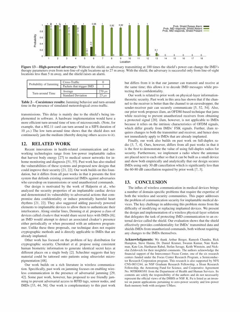
Fig. 13 shows the results of this experiment in terms of the ob-served probability of adversarial success, with the shield both onand off. It also shows the observed probability that the shield raisesan alarm, which is how the shield responds to a high-powered(above Pthresh) adversarial transmission. The figure further shows:
• When the shield is off, the adversary’s increased transmissionpower allows it to elicit IMD responses from as far as 27 meters(location 13) and from non-line-of-sight locations.
• When the shield is on, the adversary elicits IMD responses onlyfrom nearby, line-of-sight locations. Thus, the shield’s presenceraises the bar even for high-powered adversaries.
• Whenever the adversary elicits a response from the IMD in thepresence of the shield, the shield raises an alarm. The shield alsoraises an alarm in response to unsuccessful adversarial transmis-sions that are high powered and emanate from nearby locations(e.g., location 6). While this conservative alert results in falsepositives, we believe it is reasonable to alert the patient that anadversary is nearby and may succeed at controlling the IMD.
11. COEXISTENCEWe investigate how the presence of a shield affects other legit-
imate users of the medium. As explained in §2, the FCC rules formedical devices in the MICS band require such devices to monitor acandidate channel for 10 ms and avoid using occupied channels. Asa result, two pairs of honest medical devices are unlikely to sharethe same 300 KHz channel. We focus our evaluation on coexistencewith the meteorological devices that are the primary users of theMICS band (and hence can transmit even on occupied channels).
In this experiment, we position the IMD and the shield in thelocations marked on Fig. 6. We make a USRP board alternate be-tween sending unauthorized commands to the IMD and transmit-ting cross-traffic unintended for the IMD. The cross-traffic is mod-eled after the transmissions of meteorological devices, in particulara Vaisala digital radiosonde RS92-AGP [1] that uses GMSK modu-lation. For each of the adversary positions in Fig 6, we make theUSRP alternate between one packet to the IMD and one cross-traffic packet. The shield logs all packets it detects and reportswhich of them it jammed.
Post-processing of the shield’s log showed that the shield didnot jam any of the cross-traffic packets, regardless of the transmit-ter’s location. In contrast, the shield jammed all of the packets thatit detected were addressed to the IMD; see Table 2. Further, oursoftware radio implementation of the shield takes 270 ± 23 µs af-ter an adversary stops transmitting to turn around and stop its own
0
0.2
0.4
0.6
0.8
1
1 2 3 4 5 6 7 8 9 10 11 12 13 14 15 16 17 18
Pro
ba
bili
ty
Location
1 1 1 1 1 1 1 1 10.980.92 0.92
0.10.8
9
0.8
7
0.7
4
0.7
2
0.1
0.3
0 0 0 0 0 0 0 0 0 0 0 0 0
Prob. Shield Raises AlarmProb. IMD responds, Shield Absent
Prob. IMD responds, Shield Present
Figure 13—High-powered adversary: Without the shield, an adversary transmitting at 100 times the shield’s power can change the IMD’stherapy parameters even from non-line-of-sight locations up to 27 m away. With the shield, the adversary is successful only from line-of-sightlocations less than 5 m away, and the shield raises an alarm.
Probability of JammingCross-Traffic 0Packets that trigger IMD 1
Turn-around TimeAverage 270 µsStandard Deviation 23 µs
Table 2—Coexistence results: Jamming behavior and turn-aroundtime in the presence of simulated meteorological cross-traffic.
transmissions. This delay is mainly due to the shield’s being im-plemented in software. A hardware implementation would have amore efficient turn-around time of tens of microseconds. (Note, forexample, that a 802.11 card can turn around in a SIFS duration of10 µs.) The low turn-around time shows that the shield does notcontinuously jam the medium (thereby denying others access to it).
12. RELATED WORKRecent innovations in health-related communication and net-
working technologies range from low-power implantable radiosthat harvest body energy [27] to medical sensor networks for in-home monitoring and diagnosis [51, 55]. Past work has also studiedthe vulnerabilities of these systems and proposed new designs thatcould improve their security [21, 22]. Our work builds on this foun-dation, but it differs from all past works in that it presents the firstsystem that defends existing commercial IMDs against adversarieswho eavesdrop on transmissions or send unauthorized commands.
Our design is motivated by the work of Halperin et al., whoanalyzed the security properties of an implantable cardiac deviceand demonstrated its vulnerability to adversarial actions that com-promise data confidentiality or induce potentially harmful heartrhythms [21, 22]. They also suggested adding passively poweredelements to implantable devices to allow them to authenticate theirinterlocutors. Along similar lines, Denning et al. propose a class ofdevices called cloakers that would share secret keys with IMDs [6];an IMD would attempt to detect an associated cloaker’s presenceeither periodically or when presented with an unknown program-mer. Unlike these three proposals, our technique does not requirecryptographic methods and is directly applicable to IMDs that arealready implanted.
Other work has focused on the problem of key distribution forcryptographic security. Cherukuri et al. propose using consistenthuman biometric information to generate identical secret keys atdifferent places on a single body [2]. Schechter suggests that keymaterial could be tattooed onto patients using ultraviolet micro-pigmentation [48].
Our work builds on a rich literature in wireless communica-tion. Specifically, past work on jamming focuses on enabling wire-less communication in the presence of adversarial jamming [29,42]. Some past work, however, has proposed to use friendly jam-ming to prevent adversarial access to RFID tags, sensor nodes, andIMDs [33, 44, 56]. Our work is complementary to this past work
but differs from it in that our jammer can transmit and receive atthe same time; this allows it to decode IMD messages while pro-tecting their confidentiality.
Our work is related to prior work on physical-layer information-theoretic security. Past work in this area has shown that if the chan-nel to the receiver is better than the channel to an eavesdropper, thesender-receiver pair can securely communicate [5, 52, 54]. Also,our prior work proposes iJam, an OFDM-based technique that jamswhile receiving to prevent unauthorized receivers from obtaininga protected signal [20]. iJam, however, is not applicable to IMDsbecause it relies on the intrinsic characteristics of OFDM signals,which differ greatly from IMDs’ FSK signals. Further, iJam re-quires changes to both the transmitter and receiver, and hence doesnot immediately apply to IMDs that are already implanted.
Finally, our work also builds on past work on full-duplex ra-dio [3, 7, 4]. Ours, however, differs from all past works in that itis the first to demonstrate the value of using full-duplex radios forsecurity. Furthermore, we implement a radio where the antennasare placed next to each other so that it can be built as a small deviceand show both empirically and analytically that our design securesIMDs using only 30 dB cancellation which is significantly less thanthe 60-80 dB cancellation required by prior work [7, 3].
13. CONCLUSIONThe influx of wireless communication in medical devices brings
a number of domain-specific problems that require the expertise ofboth the wireless and security communities. This paper addressesthe problem of communication security for implantable medical de-vices. The key challenge in addressing this problem stems from thedifficulty of modifying or replacing implanted devices. We presentthe design and implementation of a wireless physical-layer solutionthat delegates the task of protecting IMD communication to an ex-ternal device called the shield. Our evaluation shows that the shieldeffectively provides confidentiality for IMDs’ transmitted data andshields IMDs from unauthorized commands, both without requiringany changes to the IMDs themselves.
Acknowledgments: We thank Arthur Berger, Ramesh Chandra, RickHampton, Steve Hanna, Dr. Daniel Kramer, Swarun Kumar, Nate Kush-man, Kate Lin, Hariharan Rahul, Stefan Savage, Keith Winstein, and Nick-olai Zeldovich for their insightful comments. The authors acknowledge thefinancial support of the Interconnect Focus Center, one of the six researchcenters funded under the Focus Center Research Program, a Semiconduc-tor Research Corporation program. This research is also supported by NFSCNS-0831244, an NSF Graduate Research Fellowship, a Sloan ResearchFellowship, the Armstrong Fund for Science, and Cooperative AgreementNo. 90TR0003/01 from the Department of Health and Human Services. Itscontents are solely the responsibility of the authors and do not necessarilyrepresent the official views of the DHHS or NSF. K. Fu is listed as an inven-tor on patent applications pertaining to zero-power security and low-powerflash memory both with assignee UMass.
14. REFERENCES
[1] J. Åkerberg. State-of-the-art radiosonde telemetry. In Proc. Symp.
Integrated Observing and Assimilation Systems for Atmosphere,
Oceans, and Land Surface. American Meterological Society, 2004.[2] S. Cherukuri, K. K. Venkatasubramanian, and S. K. S. Gupta. Biosec:
A biometric based approach for securing communication in wirelessnetworks of biosensors implanted in the human body. InInternational Conference on Parallel Processing Workshops, 2003.
[3] J. Choi, M. Jain, K. Srinivasan, P. Levis, and S. Katti. Achievingsingle channel, full duplex wireless communication. In Proc. ACM
MobiCom, 2010.[4] J. Choi, M. Jain, K. Srinivasan, P. Levis, and S. Katti. A working
single channel, full duplex wireless system. In Mobicom Demo, 2010.[5] I. Csiszar and J. Korner. Broadcast channels with confidential
messages. IEEE Trans. Inf. Theory, 24(3):339–348, 1978.[6] T. Denning, K. Fu, and T. Kohno. Absence makes the heart grow
fonder: New directions for implantable medical device security. InProc. USENIX Workshop on Hot Topics in Security (HotSec), 2008.
[7] M. Duarte and A. Sabharwal. Full-duplex wireless communicationsusing off-the-shelf radios: Feasibility and first results. In Asilomar
Conference on Signals, Systems, and Computers, 2010.[8] D. Eckhardt and P. Steenkiste. Measurement and analysis of the error
characteristics of an in-building wireless network. In Proc. ACM
SIGCOMM, 1996.[9] Ettus Inc. Universal Software Radio Peripheral. http://ettus.com/.[10] European Telecommunications Standard Institute. ETSI EN 301
839-1 V1.3.1, 2009.[11] C. Falcon. Inside implantable devices. Medical Design Tech., 2004.[12] Federal Communications Commission. FCC ID number search.
http://www.fcc.gov/searchtools.html.[13] Federal Communications Commission. MICS Medical Implant
Communication Services, FCC 47CFR95.601-95.673 Subpart E/IRules for MedRadio Services.
[14] K. Fu. Inside risks: Reducing the risks of implantable medicaldevices: A prescription to improve security and privacy of pervasivehealth care. Communications of the ACM, 52(6):25–27, 2009.
[15] K. Fu. Trustworthy medical device software. In Public HealthEffectiveness of the FDA 510(k) Clearance Process: Measuring
Postmarket Performance and Other Select Topics: Workshop Report.IOM (Institute of Medicine), National Academies Press, 2011.
[16] GNU Radio. http://gnuradio.org/.[17] A. Goldsmith. Wireless Communications. Cambridge University
Press, 2005.[18] S. Gollakota, F. Adib, D. Katabi, and S. Seshan. Clearing the RF
smog: Making 802.11 robust to cross-technology interference. InACM SIGCOMM, 2011.
[19] S. Gollakota, N. Ahmed, N. Zeldovich, and D. Katabi. Securein-band wireless pairing. In USENIX Security Sym., 2011.
[20] S. Gollakota and D. Katabi. Physical layer security made fast andchannel-independent. In Proc. IEEE INFOCOM, 2011.
[21] D. Halperin, T. S. Heydt-Benjamin, K. Fu, T. Kohno, and W. H.Maisel. Security and privacy for implantable medical devices. IEEEPervasive Computing, 7(1), 2008.
[22] D. Halperin, T. S. Heydt-Benjamin, B. Ransford, S. S. Clark,B. Defend, W. Morgan, K. Fu, T. Kohno, and W. H. Maisel.Pacemakers and implantable cardiac defibrillators: Software radioattacks and zero-power defenses. In Proc. IEEE Symposium onSecurity and Privacy, 2008.
[23] Industry Canada. Radio Standards Specification RSS-243: MedicalDevices Operating in the 401–406 MHz Frequency Band. SpectrumManagement and Telecommunications, 2010.
[24] International Telecommunications Union. ITU-R RecommendationRS.1346: Sharing between the meteorological aids service andmedical implant communication systems (MICS) operating in themobile service in the frequency band 401–406 MHz, 1998.
[25] Jackson Labs. Fury GPSDO. http://www.jackson-labs.com/.[26] W. C. Jakes. Microwave Mobile Communications. Wiley, 1974.[27] M. Koplow, A. Chen, D. Steingart, P. Wright, and J. Evans. Thick
film thermoelectric energy harvesting systems for biomedicalapplications. In Proc. Symp. Medical Devices and Biosensors, 2008.
[28] C. Kuo, J. Walker, and A. Perrig. Low-cost manufacturing, usabilityand security: An analysis of bluetooth simple pairing and wi-fiprotected setup. In Usable Security Workshop, 2007.
[29] Y. Liu, P. Ning, H. Dai, and A. Liu. Randomized differential DSSS:
Jamming-resistant wireless broadcast communication. In Proc. IEEE
INFOCOM, 2010.[30] J. Lopatka. Adaptive generating of the jamming signal. In Proc. IEEE
Military Communications Conference (MILCOM), 1995.[31] W. H. Maisel. Safety issues involving medical devices: Implications
of recent implantable cardioverter-defibrillator malfunctions. Journalof the American Medical Association, 2005.
[32] W. H. Maisel and T. Kohno. Improving the security and privacy ofimplantable medical devices. New England Journal of Medicine,362(13):1164–1166, 2010.
[33] I. Martinovic, P. Pichota, and J. Schmitt. Jamming for good: A freshapproach to authentic communication in WSNs. In Proc. ACM Conf.
on Wireless Network Security (WiSec), 2009.[34] Medtronic’s Paradigm Veo wireless insulin pump helps prevent
hypoglycemia. MedGadget—Internet Journal for emerging medical
technologies, 2009.[35] Medtronic Inc. CareLink Programmer. http://www.medtronic.com/.[36] Medtronic Inc. Concerto II CRT-D digital implantable cardioverter
defibrillator with cardiac resynchronization therapy.http://www.medtronic.com/.
[37] Medtronic Inc. Virtuoso DR/VR implantable cardioverterdefibrillator systems. http://medtronic.com/.
[38] H. Meyr, M. Moeneclaey, and S. A. Fechtel. Digital CommunicationReceivers: Synchronization, Channel Estimation, and SignalProcessing. Wiley, 1998.
[39] D. Panescu. Wireless communication systems for implantablemedical devices. IEEE Eng. in Medicine and Biology Mag., 2008.
[40] PCTest Engineering Labs, Inc. Certificate of compliance, fcc part 95certification, test report number: 95.220719375.lf5, 2002.
[41] PCTest Engineering Labs, Inc. Certificate of compliance, fcc part 95and en 301 839-2, test report number: 0703090168.med, 2007.
[42] C. Pöpper, M. Strasser, and S. Capkun. Jamming-resistant broadcastcommunication without shared keys. In USENIX Security Sym., 2009.
[43] B. Radunovic, D. Gunawardena, P. Key, A. Proutiere, N. Singh, H. V.Balan, and G. Dejean. Rethinking indoor wireless: Low power, lowfrequency, full-duplex. Technical report, Microsoft Research, 2009.
[44] M. Rieback, B. Crispo, and A. Tanenbaum. RFID Guardian: Abattery-powered mobile device for RFID privacy management. InProc. Australasian Conf. on Information Security and Privacy, 2005.
[45] D. Sagan. Rf integrated circuits for medical applications: Meeting thechallenge of ultra low power communication. Zarlink Semiconductor.http://stf.ucsd.edu/presentations.
[46] N. Santhapuri, R. R. Choudhury, J. Manweiler, S. Nelakuduti, S. Sen,and K. Munagala. Message in message mim: A case for reorderingtransmissions in wireless networks. In ACM HotNets-VII, 2008.
[47] K. Sayrafian-Pour, W. Yang, J. Hagedorn, J. Terrill, K. Yazdandoost,and K. Hamaguchi. Channel models for medical implantcommunication. Inter. Journal of Wireless Info. Networks, 2010.
[48] S. Schechter. Security that is meant to be skin deep: Using ultravioletmicropigmentation to store emergency-access keys for implantablemedical devices. In USENIX Workshop HealthSec, 2010.
[49] M. Scheffler, E. Hirt, and A. Caduff. Wrist-wearable medical devices:Technologies and applications. Medical Device Technology, 2003.
[50] C. E. Shannon. Communication theory of secrecy systems. BellSystem Technical Journal, 28(4):656–715, 1949.
[51] V. Shnayder, B. Chen, K. Lorincz, T. R. F. Fulford-Jones, andM. Welsh. Sensor networks for medical care. Technical ReportTR-08-05, Harvard University, 2005.
[52] M. J. Siavoshani, U. Pulleti, E. Atsan, I. Safaka, C. Fragoulia,K. Argyraki, and S. Diggavi. Exchanging secrets without usingcryptography. arXiv:1105.4991v1, 2011.
[53] D. Tse and P. Vishwanath. Fundamentals of Wireless
Communications. Cambridge University Press, 2005.[54] A. Wyner. The wire-tap channel. Bell Sys. Technical Journal, 1975.[55] S. Xiao, A. Dhamdhere, V. Sivaraman, and A. Burdett. Transmission
power control in body area sensor networks for healthcaremonitoring. IEEE Journal on Selected Areas in Comm., 2009.
[56] F. Xu, Z. Qin, C. C. Tan, B. Wang, and Q. Li. IMDGuard: Securingimplantable medical devices with the external wearable guardian. InProc. IEEE INFOCOM, 2011.
[57] Zephyr Inc. BioHarness BT. http://www.zephyr-technology.com.[58] C. Zhan, W. B. Baine, A. Sedrakyan, and S. Claudia. Cardiac device
implantation in the US from 1997 through 2004: A population-basedanalysis. Journal of General Internal Medicine, 2007.


![[Summertime Heartbeats] OPEN LETTER](https://cdn.vdocuments.site/doc/165x107/58ed7be71a28ab33688b462d/summertime-heartbeats-open-letter.jpg)