The Future ofIntermodal FreightTransportOperations, Design and Policy
Edited by
Rob KoningsSenior Researcher Freight Transport Systems, OTB ResearchInstitute for Housing, Urban and Mobility Studies, DelftUniversity of Technology, The Netherlands
Hugo Priemus Professor of System Innovation and Spatial Development,Faculty of Technology, Policy and Management, DelftUniversity of Technology, The Netherlands
Peter Nijkamp Professor of Regional, Urban and Environmental Economics,Faculty of Economics and Business Administration, FreeUniversity, Amsterdam, The Netherlands
TRANSPORT ECONOMICS, MANAGEMENT AND POLICY
Edward ElgarCheltenham, UK • Northampton, MA, USA
© Rob Konings, Hugo Priemus and Peter Nijkamp 2008
All rights reserved. No part of this publication may be reproduced, stored ina retrieval system or transmitted in any form or by any means, electronic,mechanical or photocopying, recording, or otherwise without the priorpermission of the publisher.
Published byEdward Elgar Publishing LimitedGlensanda HouseMontpellier ParadeCheltenhamGlos GL50 1UAUK
Edward Elgar Publishing, Inc.William Pratt House9 Dewey CourtNorthamptonMassachusetts 01060USA
A catalogue record for this bookis available from the British Library
Library of Congress Control Number: 2008926574
ISBN 978 1 84542 238 7
Printed and bound in Great Britain by MPG Books Ltd, Bodmin, Cornwall
8. A technical approach to the AgilePort SystemKlaus-Peter Franke
8.1 INTRODUCTION
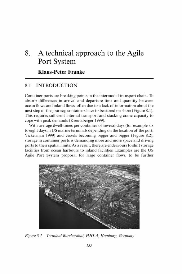
Container ports are breaking points in the intermodal transport chain. Toabsorb differences in arrival and departure time and quantity betweenocean flows and inland flows, often due to a lack of information about thenext step of the journey, containers have to be stored on shore (Figure 8.1).This requires sufficient internal transport and stacking crane capacity tocope with peak demands (Kreutzberger 1999).
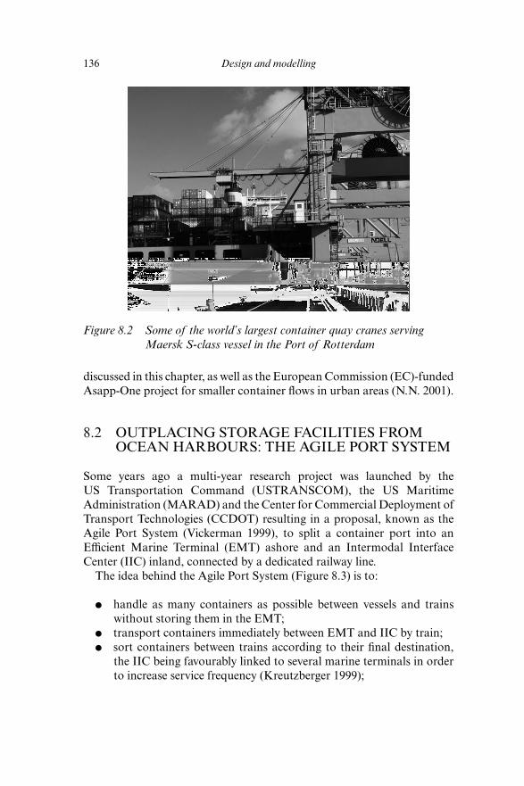
With average dwell-times per container of several days (for example sixto eight days in US marine terminals depending on the location of the port;Vickerman 1999) and vessels becoming bigger and bigger (Figure 8.2),storage in container ports is demanding more and more space and drivingports to their spatial limits. As a result, there are endeavours to shift storagefacilities from ocean harbours to inland facilities. Examples are the USAgile Port System proposal for large container flows, to be further
135
Figure 8.1 Terminal Burchardkai, HHLA, Hamburg, Germany
discussed in this chapter, as well as the European Commission (EC)-fundedAsapp-One project for smaller container flows in urban areas (N.N. 2001).
8.2 OUTPLACING STORAGE FACILITIES FROMOCEAN HARBOURS: THE AGILE PORT SYSTEM
Some years ago a multi-year research project was launched by theUS Transportation Command (USTRANSCOM), the US MaritimeAdministration (MARAD) and the Center for Commercial Deployment ofTransport Technologies (CCDOT) resulting in a proposal, known as theAgile Port System (Vickerman 1999), to split a container port into anEfficient Marine Terminal (EMT) ashore and an Intermodal InterfaceCenter (IIC) inland, connected by a dedicated railway line.
The idea behind the Agile Port System (Figure 8.3) is to:
● handle as many containers as possible between vessels and trainswithout storing them in the EMT;
● transport containers immediately between EMT and IIC by train;● sort containers between trains according to their final destination,
the IIC being favourably linked to several marine terminals in orderto increase service frequency (Kreutzberger 1999);
136 Design and modelling
Figure 8.2 Some of the world’s largest container quay cranes servingMaersk S-class vessel in the Port of Rotterdam
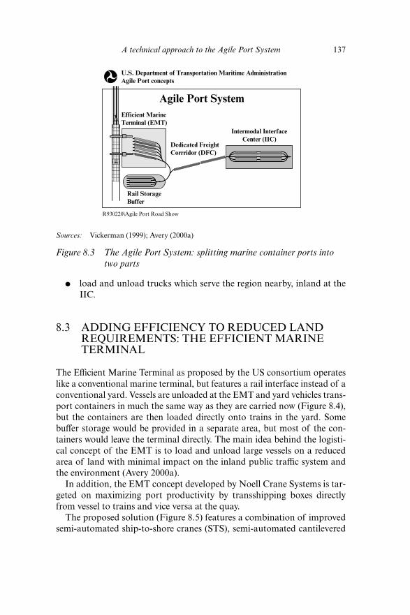
● load and unload trucks which serve the region nearby, inland at theIIC.
8.3 ADDING EFFICIENCY TO REDUCED LANDREQUIREMENTS: THE EFFICIENT MARINETERMINAL
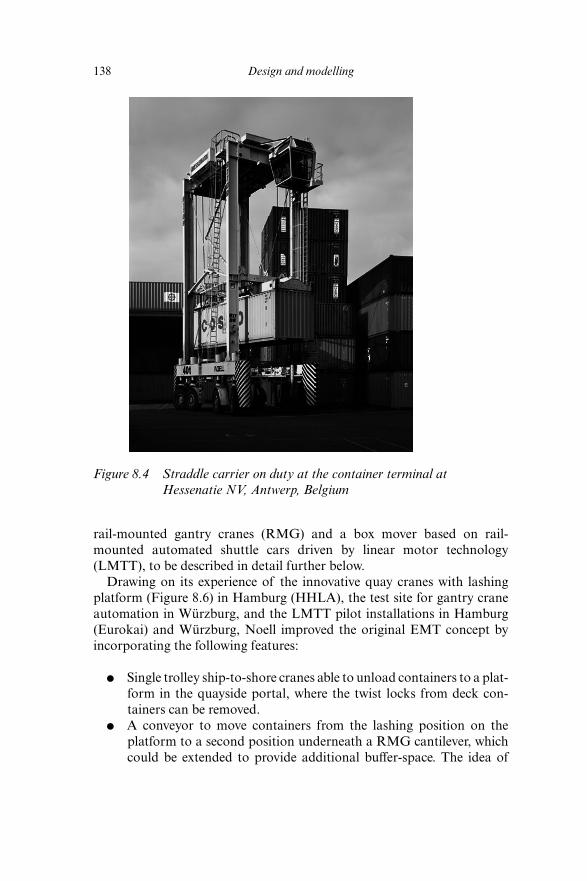
The Efficient Marine Terminal as proposed by the US consortium operateslike a conventional marine terminal, but features a rail interface instead of aconventional yard. Vessels are unloaded at the EMT and yard vehicles trans-port containers in much the same way as they are carried now (Figure 8.4),but the containers are then loaded directly onto trains in the yard. Somebuffer storage would be provided in a separate area, but most of the con-tainers would leave the terminal directly. The main idea behind the logisti-cal concept of the EMT is to load and unload large vessels on a reducedarea of land with minimal impact on the inland public traffic system andthe environment (Avery 2000a).
In addition, the EMT concept developed by Noell Crane Systems is tar-geted on maximizing port productivity by transshipping boxes directlyfrom vessel to trains and vice versa at the quay.
The proposed solution (Figure 8.5) features a combination of improvedsemi-automated ship-to-shore cranes (STS), semi-automated cantilevered
A technical approach to the Agile Port System 137
Sources: Vickerman (1999); Avery (2000a)
Figure 8.3 The Agile Port System: splitting marine container ports intotwo parts
U.S. Department of Transportation Maritime AdministrationAgile Port concepts
Efficient MarineTerminal (EMT)
Agile Port System
Rail StorageBuffer
R930220\Agile Port Road Show
Dedicated FreightCorrridor (DFC)
Intermodal InterfaceCenter (IIC)
rail-mounted gantry cranes (RMG) and a box mover based on rail-mounted automated shuttle cars driven by linear motor technology(LMTT), to be described in detail further below.
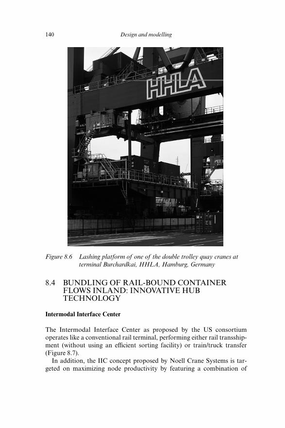
Drawing on its experience of the innovative quay cranes with lashingplatform (Figure 8.6) in Hamburg (HHLA), the test site for gantry craneautomation in Würzburg, and the LMTT pilot installations in Hamburg(Eurokai) and Würzburg, Noell improved the original EMT concept byincorporating the following features:
● Single trolley ship-to-shore cranes able to unload containers to a plat-form in the quayside portal, where the twist locks from deck con-tainers can be removed.
● A conveyor to move containers from the lashing position on theplatform to a second position underneath a RMG cantilever, whichcould be extended to provide additional buffer-space. The idea of
138 Design and modelling
Figure 8.4 Straddle carrier on duty at the container terminal atHessenatie NV, Antwerp, Belgium
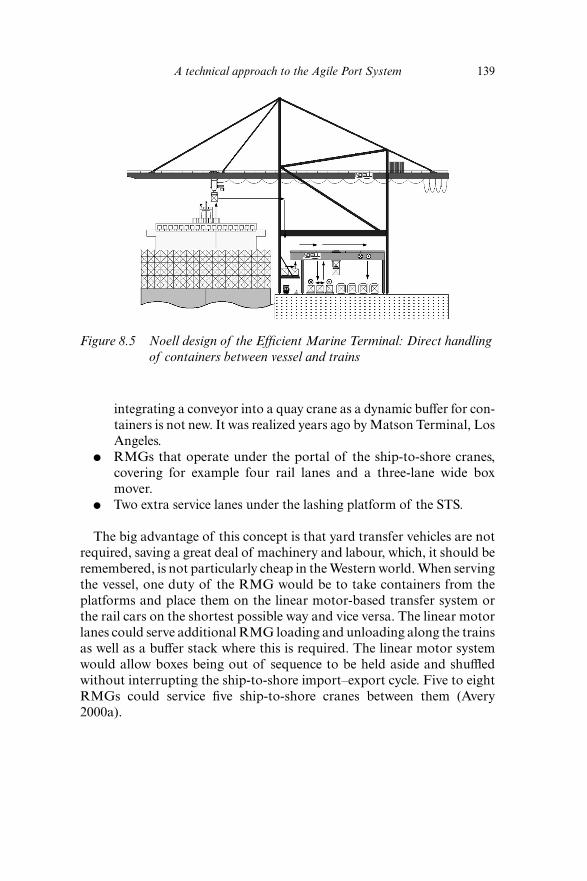
integrating a conveyor into a quay crane as a dynamic buffer for con-tainers is not new. It was realized years ago by Matson Terminal, LosAngeles.
● RMGs that operate under the portal of the ship-to-shore cranes,covering for example four rail lanes and a three-lane wide boxmover.
● Two extra service lanes under the lashing platform of the STS.
The big advantage of this concept is that yard transfer vehicles are notrequired, saving a great deal of machinery and labour, which, it should beremembered, is not particularly cheap in the Western world. When servingthe vessel, one duty of the RMG would be to take containers from theplatforms and place them on the linear motor-based transfer system orthe rail cars on the shortest possible way and vice versa. The linear motorlanes could serve additional RMG loading and unloading along the trainsas well as a buffer stack where this is required. The linear motor systemwould allow boxes being out of sequence to be held aside and shuffledwithout interrupting the ship-to-shore import–export cycle. Five to eightRMGs could service five ship-to-shore cranes between them (Avery2000a).
A technical approach to the Agile Port System 139
Figure 8.5 Noell design of the Efficient Marine Terminal: Direct handlingof containers between vessel and trains
8.4 BUNDLING OF RAIL-BOUND CONTAINERFLOWS INLAND: INNOVATIVE HUBTECHNOLOGY
Intermodal Interface Center
The Intermodal Interface Center as proposed by the US consortiumoperates like a conventional rail terminal, performing either rail transship-ment (without using an efficient sorting facility) or train/truck transfer(Figure 8.7).
In addition, the IIC concept proposed by Noell Crane Systems is tar-geted on maximizing node productivity by featuring a combination of
140 Design and modelling
Figure 8.6 Lashing platform of one of the double trolley quay cranes atterminal Burchardkai, HHLA, Hamburg, Germany
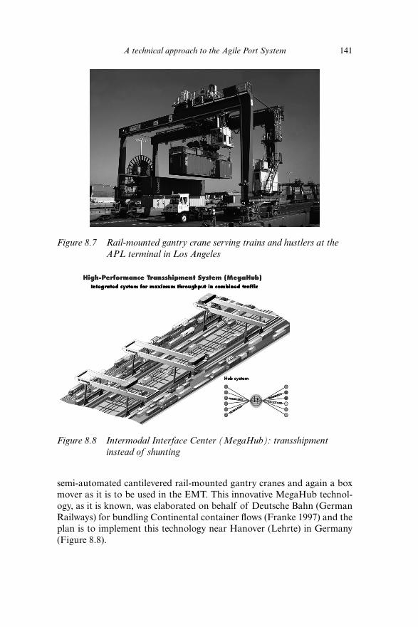
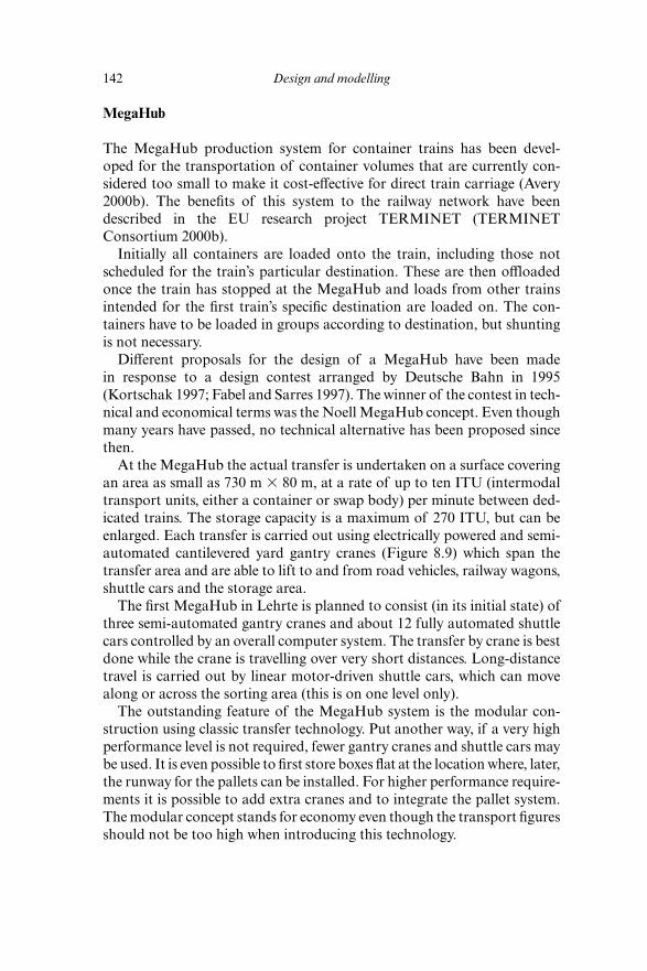
semi-automated cantilevered rail-mounted gantry cranes and again a boxmover as it is to be used in the EMT. This innovative MegaHub technol-ogy, as it is known, was elaborated on behalf of Deutsche Bahn (GermanRailways) for bundling Continental container flows (Franke 1997) and theplan is to implement this technology near Hanover (Lehrte) in Germany(Figure 8.8).
A technical approach to the Agile Port System 141
Figure 8.7 Rail-mounted gantry crane serving trains and hustlers at theAPL terminal in Los Angeles
Figure 8.8 Intermodal Interface Center (MegaHub): transshipmentinstead of shunting
MegaHub
The MegaHub production system for container trains has been devel-oped for the transportation of container volumes that are currently con-sidered too small to make it cost-effective for direct train carriage (Avery2000b). The benefits of this system to the railway network have beendescribed in the EU research project TERMINET (TERMINETConsortium 2000b).
Initially all containers are loaded onto the train, including those notscheduled for the train’s particular destination. These are then offloadedonce the train has stopped at the MegaHub and loads from other trainsintended for the first train’s specific destination are loaded on. The con-tainers have to be loaded in groups according to destination, but shuntingis not necessary.
Different proposals for the design of a MegaHub have been madein response to a design contest arranged by Deutsche Bahn in 1995(Kortschak 1997; Fabel and Sarres 1997). The winner of the contest in tech-nical and economical terms was the Noell MegaHub concept. Even thoughmany years have passed, no technical alternative has been proposed sincethen.
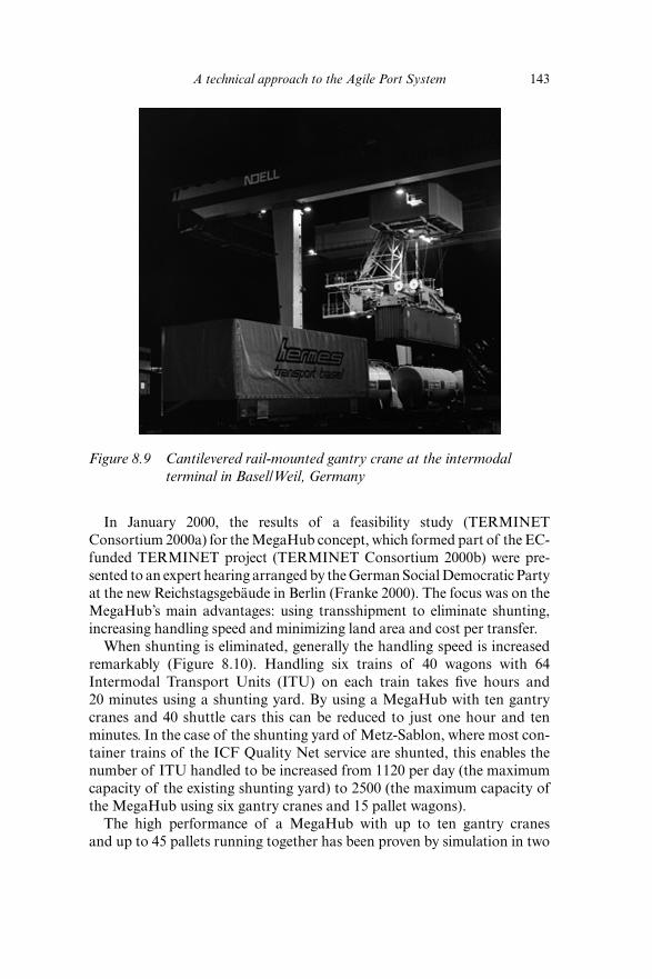
At the MegaHub the actual transfer is undertaken on a surface coveringan area as small as 730 m � 80 m, at a rate of up to ten ITU (intermodaltransport units, either a container or swap body) per minute between ded-icated trains. The storage capacity is a maximum of 270 ITU, but can beenlarged. Each transfer is carried out using electrically powered and semi-automated cantilevered yard gantry cranes (Figure 8.9) which span thetransfer area and are able to lift to and from road vehicles, railway wagons,shuttle cars and the storage area.
The first MegaHub in Lehrte is planned to consist (in its initial state) ofthree semi-automated gantry cranes and about 12 fully automated shuttlecars controlled by an overall computer system. The transfer by crane is bestdone while the crane is travelling over very short distances. Long-distancetravel is carried out by linear motor-driven shuttle cars, which can movealong or across the sorting area (this is on one level only).
The outstanding feature of the MegaHub system is the modular con-struction using classic transfer technology. Put another way, if a very highperformance level is not required, fewer gantry cranes and shuttle cars maybe used. It is even possible to first store boxes flat at the location where, later,the runway for the pallets can be installed. For higher performance require-ments it is possible to add extra cranes and to integrate the pallet system.The modular concept stands for economy even though the transport figuresshould not be too high when introducing this technology.
142 Design and modelling
In January 2000, the results of a feasibility study (TERMINETConsortium 2000a) for the MegaHub concept, which formed part of the EC-funded TERMINET project (TERMINET Consortium 2000b) were pre-sented to an expert hearing arranged by the German Social Democratic Partyat the new Reichstagsgebäude in Berlin (Franke 2000). The focus was on theMegaHub’s main advantages: using transshipment to eliminate shunting,increasing handling speed and minimizing land area and cost per transfer.
When shunting is eliminated, generally the handling speed is increasedremarkably (Figure 8.10). Handling six trains of 40 wagons with 64Intermodal Transport Units (ITU) on each train takes five hours and20 minutes using a shunting yard. By using a MegaHub with ten gantrycranes and 40 shuttle cars this can be reduced to just one hour and tenminutes. In the case of the shunting yard of Metz-Sablon, where most con-tainer trains of the ICF Quality Net service are shunted, this enables thenumber of ITU handled to be increased from 1120 per day (the maximumcapacity of the existing shunting yard) to 2500 (the maximum capacity ofthe MegaHub using six gantry cranes and 15 pallet wagons).
The high performance of a MegaHub with up to ten gantry cranesand up to 45 pallets running together has been proven by simulation in two
A technical approach to the Agile Port System 143
Figure 8.9 Cantilevered rail-mounted gantry crane at the intermodalterminal in Basel/Weil, Germany
( y )
independent doctoral theses: Dr Peter Meyer’s at the University of Hanover(Meyer 1999) and that of Dr Knut Alicke at the University of Karlsruhe(Alicke 1999).
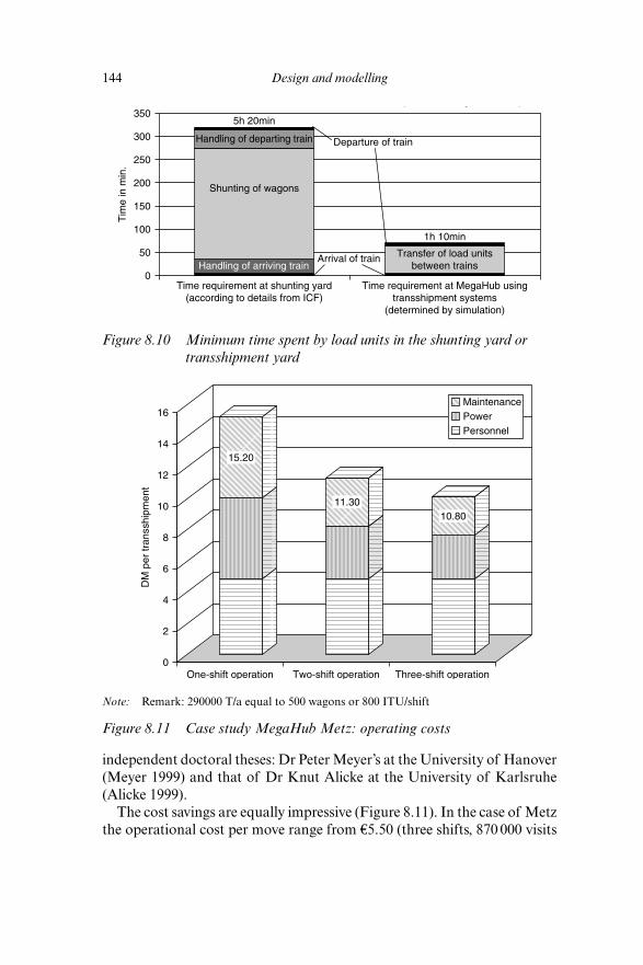
The cost savings are equally impressive (Figure 8.11). In the case of Metzthe operational cost per move range from €5.50 (three shifts, 870 000 visits
144 Design and modelling
Note: Remark: 290000 T/a equal to 500 wagons or 800 ITU/shift
Figure 8.11 Case study MegaHub Metz: operating costs
0
2
4
6
8
10
12
14
16
DM
per
tran
sshi
pmen
t
One-shift operation Two-shift operation Three-shift operation
MaintenancePowerPersonnel
15.20
11.3010.80
Figure 8.10 Minimum time spent by load units in the shunting yard ortransshipment yard
0
50
100
150
200
Tim
e in
min
.
250
300
350
Time requirement at shunting yard(according to details from ICF)
Time requirement at MegaHub usingtransshipment systems
(determined by simulation)
5h 20min
1h 10min
Handling of departing train
Shunting of wagons
Transfer of load unitsbetween trainsHandling of arriving train
Departure of train
Arrival of train
per year) to €7.75 (one shift, 290 000 visits per year) with minimum per-sonnel required. By comparison, the cost of handling 700 wagons per day(1.6 ITU per wagon) in the existing shunting yard at Metz in France is esti-mated to be €20 per ITU.
As far as total costs are concerned, a MegaHub in Lehrte (ten gantrycranes, 40 pallet wagons) able to handle 3600 wagons carrying 5760 ITUper day is estimated to require an investment of €105 million, of which€60 million is for superstructure. The cost of shunting infrastructure tohandle the same throughput at the Munich Nord One facility was €250million.
Aside from the impressive cost savings, perhaps the MegaHub’s greatestadvantage for the future is the minimal amount of land required. Taking theLehrte–Munich Nord example again, the Munich site needs 130 ha on whichto handle 3600 wagons per day, compared with just 10 ha for a MegaHub.
8.5 HIGH-CAPACITY BOX MOVER FORCOLLECTION AND DISTRIBUTION ALONGTHE TRAINS
Part of the Efficient Marine Terminal as well as of the Intermodal InterfaceCenter (MegaHub) is a horizontal transport system for the sorting of boxesalong the trains featuring linear motor-based transfer technology. Due toheavy obstruction, there would be no efficient container handling possiblewithout such a horizontal transport system when loading and unloadingtrains by several gantry cranes using the same track.
Linear Motor-Based Transfer Technology (LMTT)
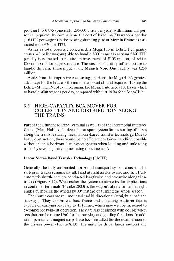
Generally the fully automated horizontal transport system consists of asystem of tracks running parallel and at right angles to one another. Fullyautomatic shuttle cars are conducted lengthwise and crosswise along thesetracks (Figure 8.12). What makes the system so attractive for applicationsin container terminals (Franke 2000) is the wagon’s ability to turn at rightangles by moving the wheels by 90° instead of turning the whole wagon.
The shuttle cars are rail-mounted and bi-directional (straight ahead andsideways). They comprise a base frame and a loading platform that iscapable of carrying loads up to 41 tonnes, which may well be increased to54 tonnes for twin-lift operation. They are also equipped with double wheelsets that can be rotated 90° for the carrying and guiding functions. In add-ition, permanent magnet strips have been installed for the transmission ofthe driving power (Figure 8.13). The units for drive (linear motors) and
A technical approach to the Agile Port System 145
position detection are integrated into the runway. The control system is sta-tionary.
The runway may consist of ordinary UIC 60 rails, mounted on steel twinsleepers. To make it possible to turn the wheel sets (of the shuttle cars), acircular steel surface with transverse guides has been fitted at the crossingpoints, that is, the intersections of the longitudinal and transverse travel-ling rails (Figure 8.12).
146 Design and modelling
Figure 8.12 LMTT pallet wagon propelled by electromagnetic force
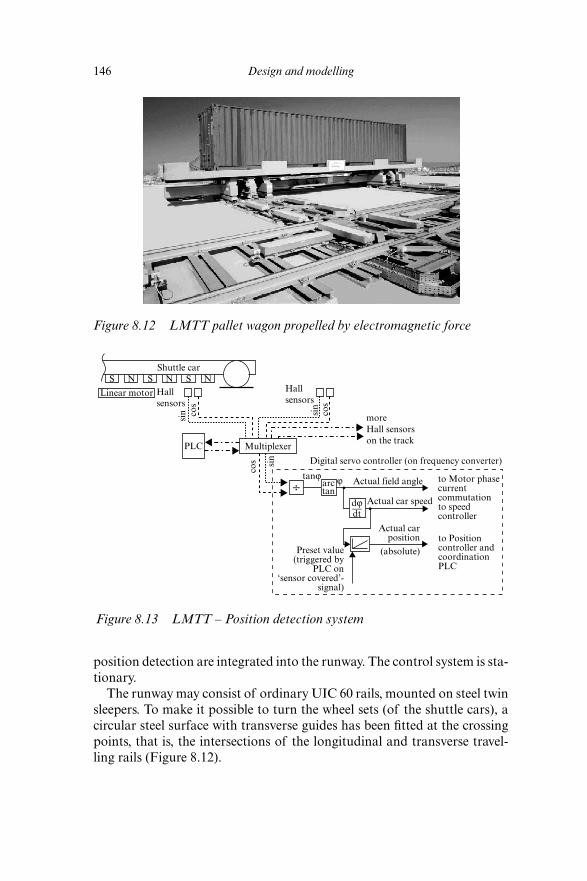
Figure 8.13 LMTT – Position detection system
Shuttle car
Linear motor Hallsensors
Hallsensors
PLC Multiplexer
arctan
Digital servo controller (on frequency converter)
Actual car speed
Actual field angle
dϕ—dt
tanϕ÷
moreHall sensorson the track
Actual carposition
Preset value(triggered by
PLC on‘sensor covered’-
signal)
(absolute)
to Motor phasecurrentcommutationto speedcontroller
to Positioncontroller andcoordinationPLC
S S SN N
sin
sin
sin
cos
cos
cos
N
ϕ
A major advantage is that the chassis does not need an engine, brakes,gears, a Programmable Logic Control (PLC) or sensors. The shuttle carsare driven by means of contact-free linear synchronous motors, which aredistributed over the track according to the requirement of driving force.They act on the magnets located on the underside of the shuttle cars. It ispossible to set a variable speed by means of a mobile electromagnetic field,generated using a frequency converter. A contact-free actual positiondetection system (Hall sensors) is integrated into the runway and respondsto the individual magnets located on the shuttle cars. This enables theabsolute position of the shuttle car to be determined and supplies the inputvalues required to ensure that the linear drives are supplied with power andswitched over in the correct order.
The shuttle cars move at 3 m/s with an acceleration of 0.3 m/s2 and canbe positioned with an accuracy of �/� 3 mm. With so few moving parts,maintenance costs are kept to an absolute minimum and no fossil fuel isrequired (Bauer 1998).
The linear motor-driven transfer technology was initially developed withfunding from the German Ministry of Research, BMB�F (Consortium1997). Between 1995 and 1998, test and demonstration plants (on a scale of1:1) were set up at the Port of Hamburg, Eurokai (Wölper and Huth 1997),at the headquarters of Noell Crane Systems GmbH in Würzburg (both inGermany) and on the plant grounds of Noell Crane Systems (China) Ltd.in Xiamen.
Simulation of the Box Mover Based on LMTT
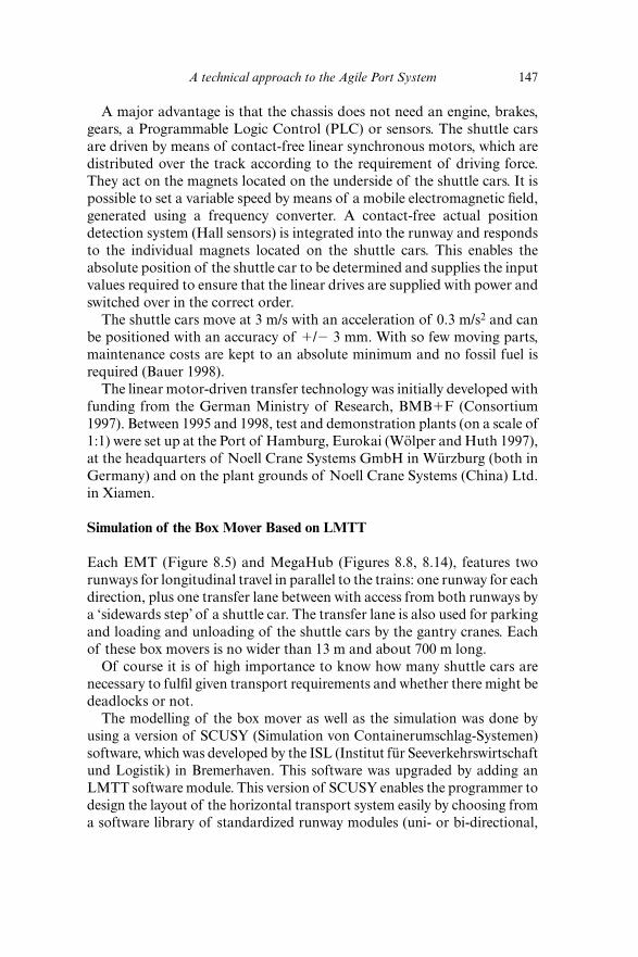
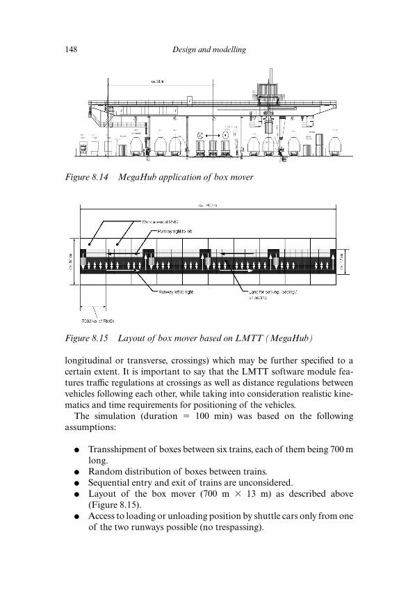
Each EMT (Figure 8.5) and MegaHub (Figures 8.8, 8.14), features tworunways for longitudinal travel in parallel to the trains: one runway for eachdirection, plus one transfer lane between with access from both runways bya ‘sidewards step’ of a shuttle car. The transfer lane is also used for parkingand loading and unloading of the shuttle cars by the gantry cranes. Eachof these box movers is no wider than 13 m and about 700 m long.
Of course it is of high importance to know how many shuttle cars arenecessary to fulfil given transport requirements and whether there might bedeadlocks or not.
The modelling of the box mover as well as the simulation was done byusing a version of SCUSY (Simulation von Containerumschlag-Systemen)software, which was developed by the ISL (Institut für Seeverkehrswirtschaftund Logistik) in Bremerhaven. This software was upgraded by adding anLMTT software module. This version of SCUSY enables the programmer todesign the layout of the horizontal transport system easily by choosing froma software library of standardized runway modules (uni- or bi-directional,
A technical approach to the Agile Port System 147
longitudinal or transverse, crossings) which may be further specified to acertain extent. It is important to say that the LMTT software module fea-tures traffic regulations at crossings as well as distance regulations betweenvehicles following each other, while taking into consideration realistic kine-matics and time requirements for positioning of the vehicles.
The simulation (duration � 100 min) was based on the followingassumptions:
● Transshipment of boxes between six trains, each of them being 700 mlong.
● Random distribution of boxes between trains.● Sequential entry and exit of trains are unconsidered.● Layout of the box mover (700 m � 13 m) as described above
(Figure 8.15).● Access to loading or unloading position by shuttle cars only from one
of the two runways possible (no trespassing).
148 Design and modelling
Figure 8.14 MegaHub application of box mover
Figure 8.15 Layout of box mover based on LMTT (MegaHub)
● Shuttle cars dedicated to selected transport relations.● No optimization of empty run of shuttle cars.● Geometry and kinematics of the shuttle cars derived from the
MegaHub Lehrte project.● Fixed length of work area per (gantry) crane is 700 m/no. of cranes
(see Meyer 1999; Alicke 1999 for variable length of work areas).● No obstruction by neighbouring cranes (see Meyer 1999 for obstruc-
tion by neighbouring cranes).● Geometry and kinematics of the gantry cranes derived from the
MegaHub Lehrte project.● Transport requirement � number of visits per time unit (� boxes/100
min).● Differentiation between direct and indirect (via box mover) trans-
shipments.● Number of visits � number of direct � number of indirect trans-
shipments.● Number of direct transshipments � 38 � approx. no. of visits /
number of cranes (see Alicke 1999).● Number of cranes and number of shuttle cars are subject to change.
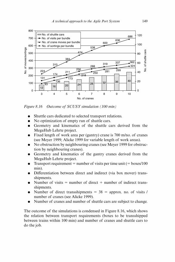
The outcome of the simulations is condensed in Figure 8.16, which showsthe relation between transport requirements (boxes to be transshippedbetween trains within 100 min) and number of cranes and shuttle cars todo the job.
A technical approach to the Agile Port System 149
Figure 8.16 Outcome of SCUSY simulation (100 min)
12 16 20 24 28 32 36 40131
174211
256288
319 337 362
224
310
384
474
538
600636
686
93136
173218
250 281 299
324
0
100
200
300
400
500
600
700
800
3 4 5 6 7 8 9 10
No. of cranes
No.
of m
oves
/sor
tings
0
20
40
60
80
100
120
No.
of s
huttl
e ca
rs
No. of shuttle carsNo. of visits per bundleNo. of crane moves per bundleNo. of sortings per bundle
Based on the assumptions above it is possible to do a maximum ofapproximately 360 (� 6 � 60) direct and indirect transshipments betweensix trains by operating ten gantry cranes, which means to completely inter-change boxes between trains having a capacity of 60 boxes each within100 minutes.
By doing maximum performance 360 (1–1/10) � 324 boxes have to bemoved by 40 shuttle cars. As a rule it can be said that four shuttle cars areneeded to serve one gantry crane in such a MegaHub application.
8.6 CONCLUSIONS
In order to overcome spatial limits in marine container terminals there is ademand to split ports into an Efficient Marine Terminal (EMT) part ashoreand an Intermodal Interface Center (IIC) inland, both connected by a ded-icated railway line (Agile Port System).
By decoupling vessel- and train-side container handling at the EMTthere is a technical solution available to transship containers between vesseland train and vice versa directly at the quay without a loss in performance.As soon as trains are loaded, import containers may be transferred by railto the IIC. There they will be rearranged between trains according to theirfinal destination or transferred to trucks for distribution. Export contain-ers will be dealt with accordingly in the opposite direction. Instead ofstoring empties and import boxes at the sea terminal these boxes may bestored near the customer at the begin or end terminals inland, thus con-tributing to their small margins.
The IIC can be realized by using the Noell MegaHub technology beingdeveloped for an inland hub to be installed in Hanover (Lehrte), Germany,as it is planned by DB. In such a MegaHub it will be possible to transshipup to 360 boxes between trains within only 100 minutes. Other locationswhere the MegaHub technology would be very suited for implementationare so-called gateway terminals near Zurich (Limmattal) and Basel to berealized by SBB (N.N. 2003a; N.N. 2003b).
REFERENCES
Alicke, K. (1999), Modellierung und Optimierung von mehrstufigen Umschlagsystemen,Doctoral thesis approved by the University of Karlsruhe, Karlsruhe: Scientificreports of the Institut für Fördertechnik und Logistiksysteme of the University ofKarlsruhe.
Avery, P. (2000a), ‘Inventing a way out of trouble’, Cargo Systems, 27 (8), London:IIR Publications.
150 Design and modelling
Avery, P. (2000b), ‘MegaHub gains momentum’, Cargo Systems, London: IIRPublications.
Bauer, R. (1998), ‘Innovative linear motor-based transfer technology allows intelli-gent container handling’, presentation for the ‘EURNAV 98’ conference, Hanover.
Consortium (1997), ‘Container-Transportsysteme der Zukunft’, R&D project on‘behalf of the German Federal Ministry of Education, Science, Research andTechnology BMB�F.
Fabel, P. and D. Sarres (1997), ‘Umschlagtechnologien für den KombiniertenVerkehr’, Eisenbahntechnische Rundschau 46, H. 10.
Franke, K.-P. (1997), Lehrte/Hannover – Mega-Drehscheibe für den KombiniertenVerkehr, Symposium: Europe towards Intermodal Transport, Vienna: EuropeanIntermodal Association (EIA).
Franke, K.-P. (2000), ‘Innovative Mega-Drehscheibe für den KombiniertenVerkehr – Expert hearing: Zukunftsperspektiven des Kombinierten Verkehrs –Technische Innovationen und Systeme’, SPD fraction in the Bundestag, Berlin.
Kortschak, B.H. (1997), ‘Vertikalrangieren – das alternative Rangierkonzept’, DerEisenbahnIngenieur, Hamburg: Tetzlaff Verlag.
Kreutzberger, E. (1999), ‘Innovative Networks and New-generation Terminals forIntermodal Transport – Improving the Cost-quality Ratio by Bundling Flows’,Delft: The Netherlands TRAIL Research School, TRAIL 5th PhD Year Congress.
Meyer, P. (1999), ‘Entwicklung eines Simulationsprogramms für Umschlagterminalsdes Kombinierten Verkehrs’, Doctoral thesis approved by the University ofHanover, Aachen: Shaker Verlag.
N.N. (2001), ‘Six TEU AGVs’, World Cargo News, http:www.worldcargonews.com/htm/n20010301.058515.htm.
N.N. (2003a), ‘Neues KV-Terminal bei Zürich’, Eisenbahntechnische Rundschau, 54,Hamburg: Tetzlaff Verlag.
N.N. (2003b), ‘SBB Cargo investiert in Basel – Terminal Basel Nord soll europäis-che Drehscheibe werden’, DVZ – Deutsche Verkehrs Zeitung, Hamburg:Deutscher Verkehrs-Verlag.
TERMINET Consortium (2000a), ‘Performance analyses – 5 new-generation ter-minal case studies’ (Deliverable D10), Report for DG – VII of the EuropeanCommission.
TERMINET Consortium (2000b), ‘Final report for publication’, Report for DG –VII of the European Commission.
Vickerman, M.J. (1999), ‘Agile Port concept’, http://www.transystems.com.Wölper, A. and E. Huth (1997), ‘Introducing Linear Motor-based Transfer
Technology to a Container Handling Environment’, Barcelona: TerminalOperations Conference.
A technical approach to the Agile Port System 151


