PETE 613(2005A)
Slide — 1Wellbore Phenomena
T.A. Blasingame, Texas A&M U.Department of Petroleum Engineering
Texas A&M UniversityCollege Station, TX 77843-3116
+1.979.845.2292 — [email protected]
Petroleum Engineering 613Natural Gas Engineering
Texas A&M University
Lecture 07:Wellbore Phenomena
PETE 613(2005A)
Slide — 2Wellbore Phenomena
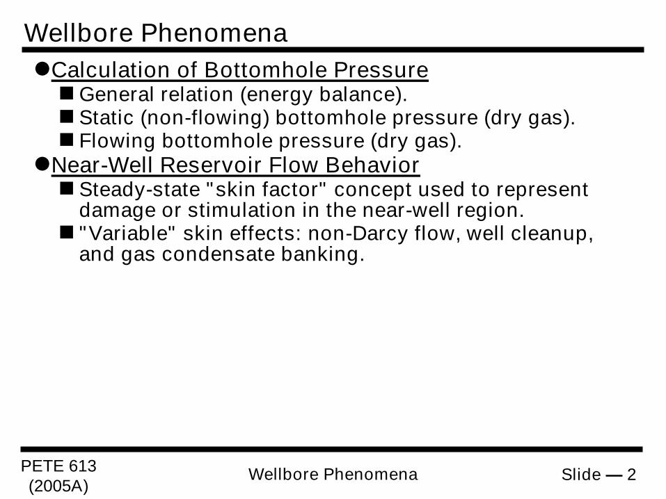
Wellbore PhenomenaCalculation of Bottomhole PressureGeneral relation (energy balance).Static (non-flowing) bottomhole pressure (dry gas).Flowing bottomhole pressure (dry gas).
Near-Well Reservoir Flow BehaviorSteady-state "skin factor" concept used to represent
damage or stimulation in the near-well region."Variable" skin effects: non-Darcy flow, well cleanup,
and gas condensate banking.
PETE 613(2005A)
Slide — 3Wellbore Phenomena
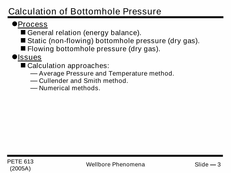
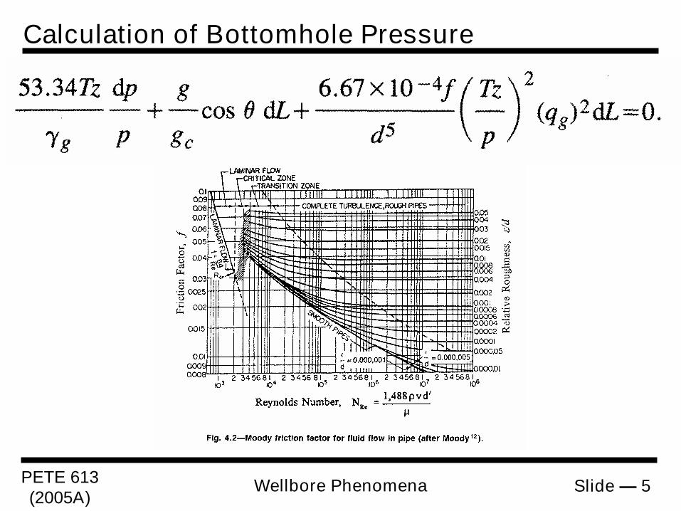
Calculation of Bottomhole PressureProcessGeneral relation (energy balance).Static (non-flowing) bottomhole pressure (dry gas).Flowing bottomhole pressure (dry gas).
IssuesCalculation approaches:
— Average Pressure and Temperature method.— Cullender and Smith method.— Numerical methods.
PETE 613(2005A)
Slide — 4Wellbore Phenomena
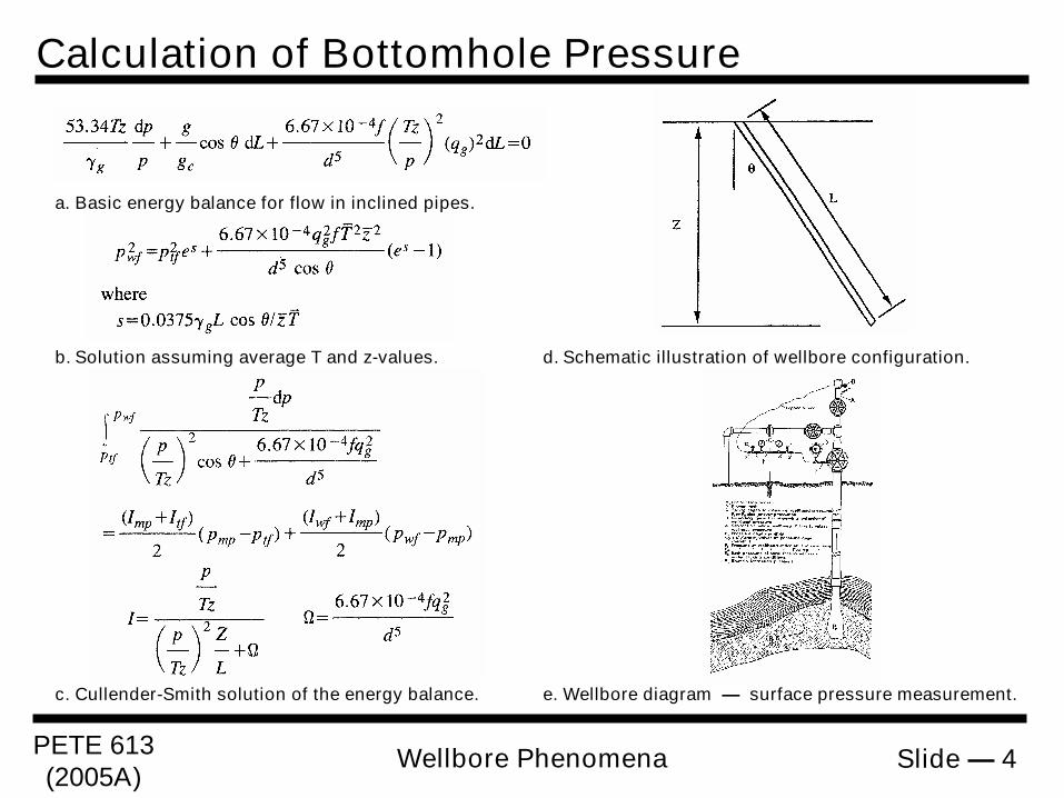
Calculation of Bottomhole Pressure
a. Basic energy balance for flow in inclined pipes.
d. Schematic illustration of wellbore configuration.b. Solution assuming average T and z-values.
e. Wellbore diagram — surface pressure measurement.c. Cullender-Smith solution of the energy balance.
PETE 613(2005A)
Slide — 5Wellbore Phenomena
Calculation of Bottomhole Pressure
PETE 613(2005A)
Slide — 6Wellbore Phenomena
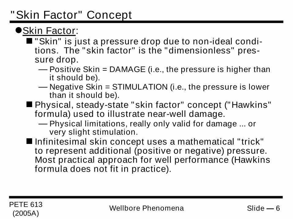
"Skin Factor" ConceptSkin Factor:"Skin" is just a pressure drop due to non-ideal condi-
tions. The "skin factor" is the "dimensionless" pres-sure drop.— Positive Skin = DAMAGE (i.e., the pressure is higher than
it should be).— Negative Skin = STIMULATION (i.e., the pressure is lower
than it should be).Physical, steady-state "skin factor" concept ("Hawkins"
formula) used to illustrate near-well damage.— Physical limitations, really only valid for damage ... or
very slight stimulation.Infinitesimal skin concept uses a mathematical "trick"
to represent additional (positive or negative) pressure.Most practical approach for well performance (Hawkinsformula does not fit in practice).
PETE 613(2005A)
Slide — 7Wellbore Phenomena
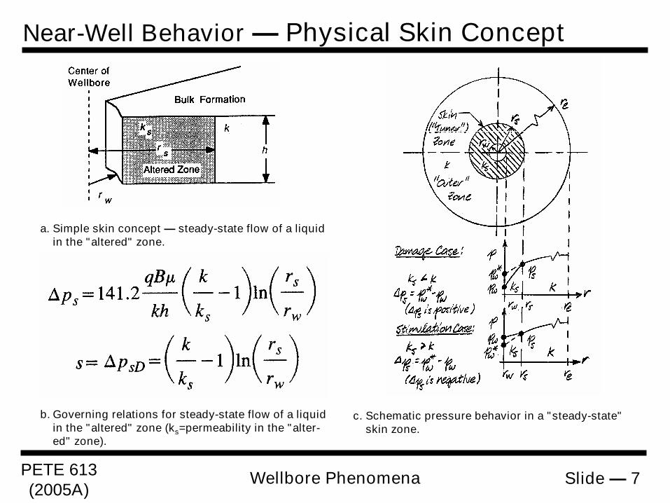
Near-Well Behavior — Physical Skin Concept
a. Simple skin concept — steady-state flow of a liquidin the "altered" zone.
c. Schematic pressure behavior in a "steady-state"skin zone.
b. Governing relations for steady-state flow of a liquidin the "altered" zone (ks=permeability in the "alter-ed" zone).
PETE 613(2005A)
Slide — 8Wellbore Phenomena
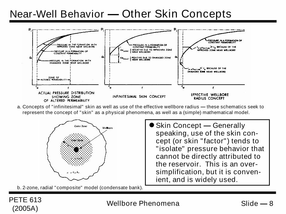
a. Concepts of "infinitesimal" skin as well as use of the effective wellbore radius — these schematics seek torepresent the concept of "skin" as a physical phenomena, as well as a (simple) mathematical model.
b. 2-zone, radial "composite" model (condensate bank).
Skin Concept — Generallyspeaking, use of the skin con-cept (or skin "factor") tends to"isolate" pressure behavior thatcannot be directly attributed tothe reservoir. This is an over-simplification, but it is conven-ient, and is widely used.
Near-Well Behavior — Other Skin Concepts
PETE 613(2005A)
Slide — 9Wellbore Phenomena
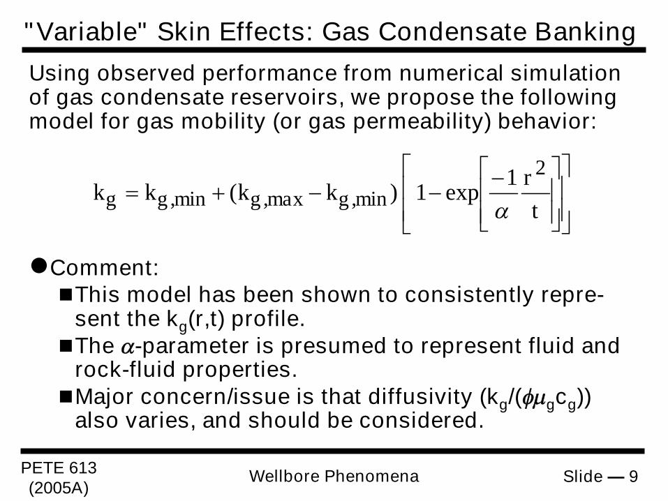
Comment:This model has been shown to consistently repre-
sent the kg(r,t) profile.The -parameter is presumed to represent fluid and
rock-fluid properties.Major concern/issue is that diffusivity (kg/(gcg))
also varies, and should be considered.
Using observed performance from numerical simulationof gas condensate reservoirs, we propose the followingmodel for gas mobility (or gas permeability) behavior:
tr
kkkk min,gmax,gmin,gg21
exp1)(
"Variable" Skin Effects: Gas Condensate Banking
PETE 613(2005A)
Slide — 10Wellbore Phenomena
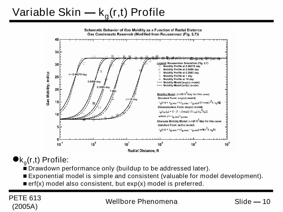
Variable Skin — kg(r,t) Profile
kg(r,t) Profile:Drawdown performance only (buildup to be addressed later).Exponential model is simple and consistent (valuable for model development).erf(x) model also consistent, but exp(x) model is preferred.
PETE 613(2005A)
Slide — 11Wellbore Phenomena
Variable Skin — So(r,t) Profile
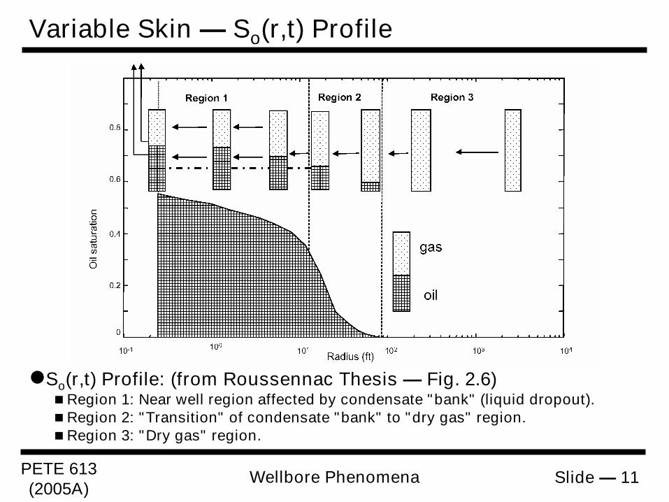
So(r,t) Profile: (from Roussennac Thesis — Fig. 2.6)Region 1: Near well region affected by condensate "bank" (liquid dropout).Region 2: "Transition" of condensate "bank" to "dry gas" region.Region 3: "Dry gas" region.
PETE 613(2005A)
Slide — 12Wellbore Phenomena
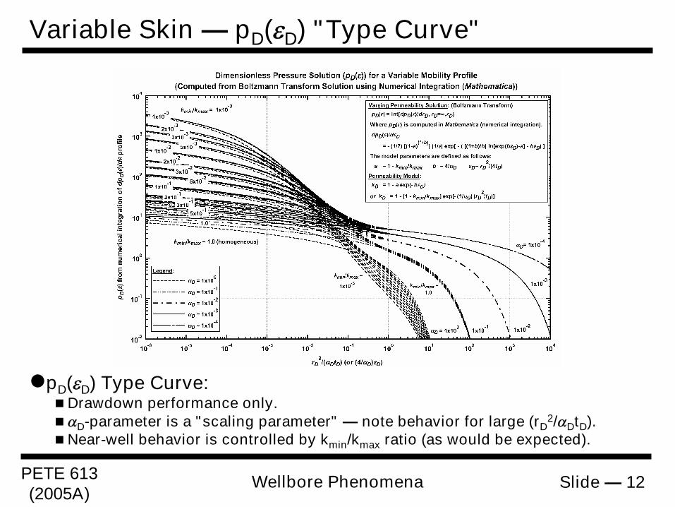
Variable Skin — pD(D) "Type Curve"
pD(D) Type Curve:Drawdown performance only.D-parameter is a "scaling parameter" — note behavior for large (rD
2/DtD).Near-well behavior is controlled by kmin/kmax ratio (as would be expected).
PETE 613(2005A)
Slide — 13Wellbore Phenomena
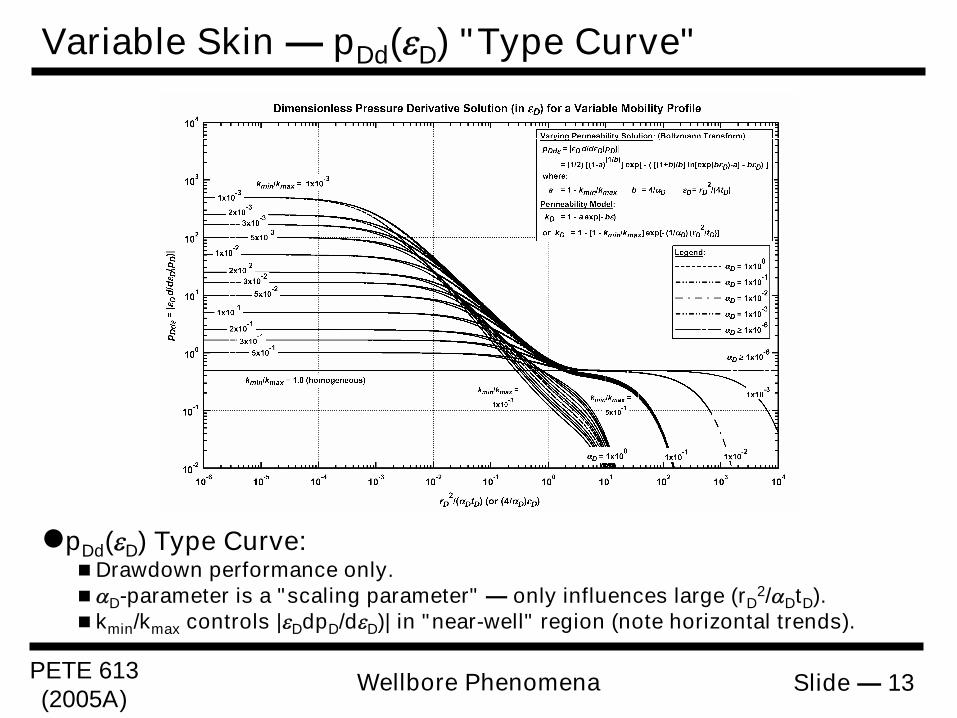
Variable Skin — pDd(D) "Type Curve"
pDd(D) Type Curve:Drawdown performance only.D-parameter is a "scaling parameter" — only influences large (rD
2/DtD).kmin/kmax controls |DdpD/dD)| in "near-well" region (note horizontal trends).
PETE 613(2005A)
Slide — 14Wellbore Phenomena
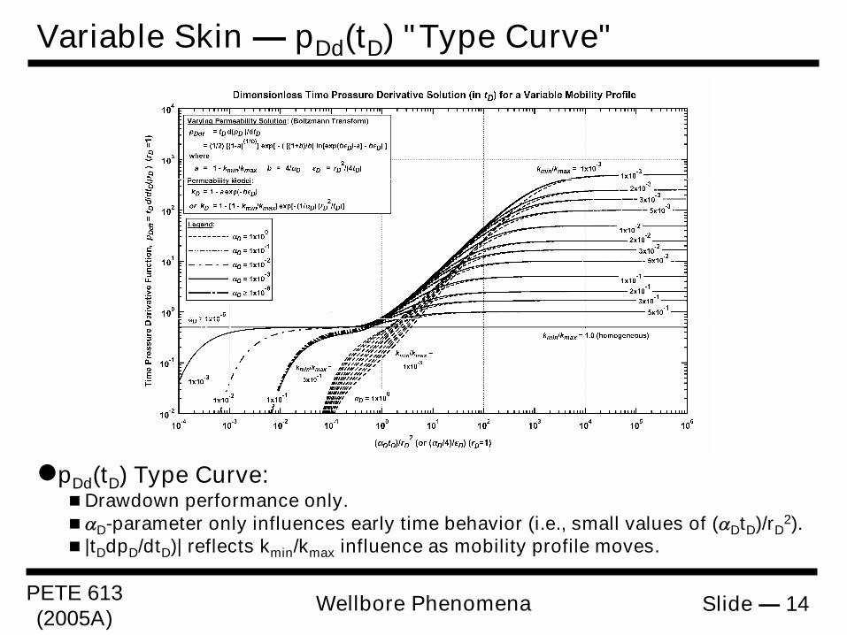
Variable Skin — pDd(tD) "Type Curve"
pDd(tD) Type Curve:Drawdown performance only.D-parameter only influences early time behavior (i.e., small values of (DtD)/rD
2).|tDdpD/dtD)| reflects kmin/kmax influence as mobility profile moves.
PETE 613(2005A)
Slide — 15Wellbore Phenomena
Validation: Literature Data ― Case 1
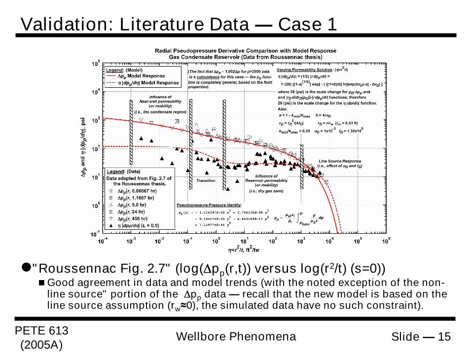
"Roussennac Fig. 2.7" (log(pp(r,t)) versus log(r2/t) (s=0))Good agreement in data and model trends (with the noted exception of the non-
line source" portion of the pp data — recall that the new model is based on theline source assumption (rw≈0), the simulated data have no such constraint).
PETE 613(2005A)
Slide — 16Wellbore Phenomena
Validation: Literature Data ― Case 2
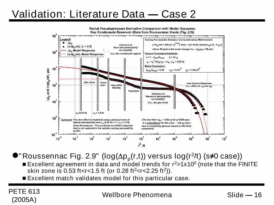
"Roussennac Fig. 2.9" (log(pp(r,t)) versus log(r2/t) (s≠0 case))Excellent agreement in data and model trends for r2>1x100 (note that the FINITE
skin zone is 0.53 ft<r<1.5 ft (or 0.28 ft2<r<2.25 ft2)).Excellent match validates model for this particular case.
PETE 613(2005A)
Slide — 17Wellbore Phenomena
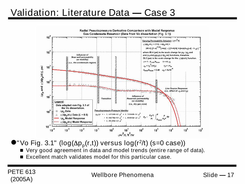
"Vo Fig. 3.1" (log(pp(r,t)) versus log(r2/t) (s=0 case)) Very good agreement in data and model trends (entire range of data). Excellent match validates model for this particular case.
Validation: Literature Data ― Case 3
PETE 613(2005A)
Slide — 18Wellbore Phenomena
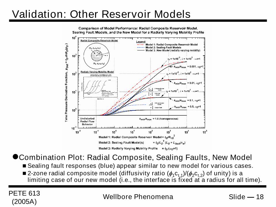
Validation: Other Reservoir Models
Combination Plot: Radial Composite, Sealing Faults, New ModelSealing fault responses (blue) appear similar to new model for various cases.2-zone radial composite model (diffusivity ratio (1ct,1)/(2ct,2) of unity) is a
limiting case of our new model (i.e., the interface is fixed at a radius for all time).
PETE 613(2005A)
Slide — 19Wellbore Phenomena
T.A. Blasingame, Texas A&M U.Department of Petroleum Engineering
Texas A&M UniversityCollege Station, TX 77843-3116
+1.979.845.2292 — [email protected]
Petroleum Engineering 613Natural Gas Engineering
Texas A&M University
Lecture 07:Wellbore Phenomena
(End of Lecture)


