A Division of: - 1 -
Theratherm
Swimming Pool/Spa Heat Pump User and Service manual
A Division of: - 2 -
INDEX
1. Specifications
2. Dimension
3. Installation and connection
4. Accessories
5. Electrical Wiring
6. Display Controller Operation
7. Troubleshooting
8. Exploded Diagram
9. Maintenance
10. Warranty
Thank you for purchasing a Theratherm Heat Pump for your pool or spa heating. Heat Pumps use the
ambient air temperature to heat your pool or spa water efficiently. Heat Pumps perform better with warmer
ambient temperatures & it will heat your water and maintain constant temperature whilst the ambient air
temperature is between -7 to 40℃. The use of a heat pump will extend your swimming season & provide
extra enjoyment for you and your family.
ATTENTION: This manual includes all the necessary information regarding the use and the
installation of your heat pump.
The installer must read the manual and attentively follow the instructions in implementation and
maintenance.
The installer is responsible for the installation of the product and should follow all the instructions of the
manufacturer and the regulations in application. Incorrect installation against the manual implies the
exclusion of the entire guarantee and warranty.
The manufacturer declines any responsibility for the damage caused to people, objects and errors due to
incorrect installation. It is the owners responsibility to ensure that the pool or spa water maintains correct
water chemistry balance as bad water chemistry can damage the heat pump internal components which
will not be covered under this warranty. Any usage outside of what is stated within this manual or its
designed purpose of manufacturing will be regarded as dangerous and is not recommended.
A Division of: - 3 -
WARNING: Please always shut off the power supply if you need to open the heat pump cabinet to work
inside the heat pump. As this is an electrical product there is high voltage electricity inside. Any electrical
connections and/or repairs should be conducted by a licensed electrician.
WARNING: When using the 10mtr external control panel extension please ensure the display controller is
located in a dry area. Also keep the insulation cover closed to protect the display on the controller from
being damaged by humidity and possible rain.
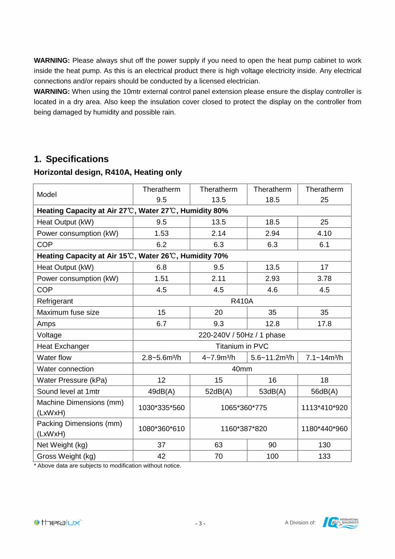
1. Specifications
Horizontal design, R410A, Heating only
Model Theratherm
9.5
Theratherm
13.5
Theratherm
18.5
Theratherm
25
Heating Capacity at Air 27℃, Water 27℃, Humidity 80%
Heat Output (kW) 9.5 13.5 18.5 25
Power consumption (kW) 1.53 2.14 2.94 4.10
COP 6.2 6.3 6.3 6.1
Heating Capacity at Air 15℃, Water 26℃, Humidity 70%
Heat Output (kW) 6.8 9.5 13.5 17
Power consumption (kW) 1.51 2.11 2.93 3.78
COP 4.5 4.5 4.6 4.5
Refrigerant R410A
Maximum fuse size 15 20 35 35
Amps 6.7 9.3 12.8 17.8
Voltage 220-240V / 50Hz / 1 phase
Heat Exchanger Titanium in PVC
Water flow 2.8~5.6m³/h 4~7.9m³/h 5.6~11.2m³/h 7.1~14m³/h
Water connection 40mm
Water Pressure (kPa) 12 15 16 18
Sound level at 1mtr 49dB(A) 52dB(A) 53dB(A) 56dB(A)
Machine Dimensions (mm)
(LxWxH) 1030*335*560 1065*360*775 1113*410*920
Packing Dimensions (mm)
(LxWxH) 1080*360*610 1160*387*820 1180*440*960
Net Weight (kg) 37 63 90 130
Gross Weight (kg) 42 70 100 133
* Above data are subjects to modification without notice.
A Division of: - 4 -
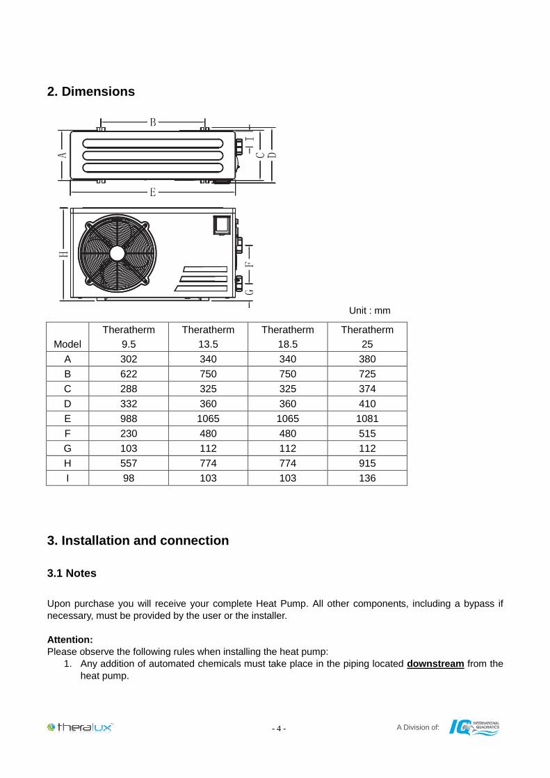
2. Dimensions
Unit : mm
Model
Theratherm
9.5
Theratherm
13.5
Theratherm
18.5
Theratherm
25
A 302 340 340 380
B 622 750 750 725
C 288 325 325 374
D 332 360 360 410
E 988 1065 1065 1081
F 230 480 480 515
G 103 112 112 112
H 557 774 774 915
I 98 103 103 136
3. Installation and connection
3.1 Notes
Upon purchase you will receive your complete Heat Pump. All other components, including a bypass if
necessary, must be provided by the user or the installer.
Attention:
Please observe the following rules when installing the heat pump:
1. Any addition of automated chemicals must take place in the piping located downstream from the
heat pump.
A Division of: - 5 -
2. Install a bypass if the water flow from the swimming pool pump is more than 20% greater than the
allowable flow through the heat exchanger of the heat pump.
3. Install the heat pump above the water level of the swimming pool.
4. Always place the heat pump on a solid foundation and use the included rubber mounts to avoid
vibration and noise.
5. Always hold the heat pump upright. If the unit has been held at an angle, wait at least 24 hours
before starting the heat pump.
3.2 Heat pump location
The unit will work properly in any desired location as long as the following three items are present:
1. Fresh air – 2. Electricity – 3. Swimming pool filtration
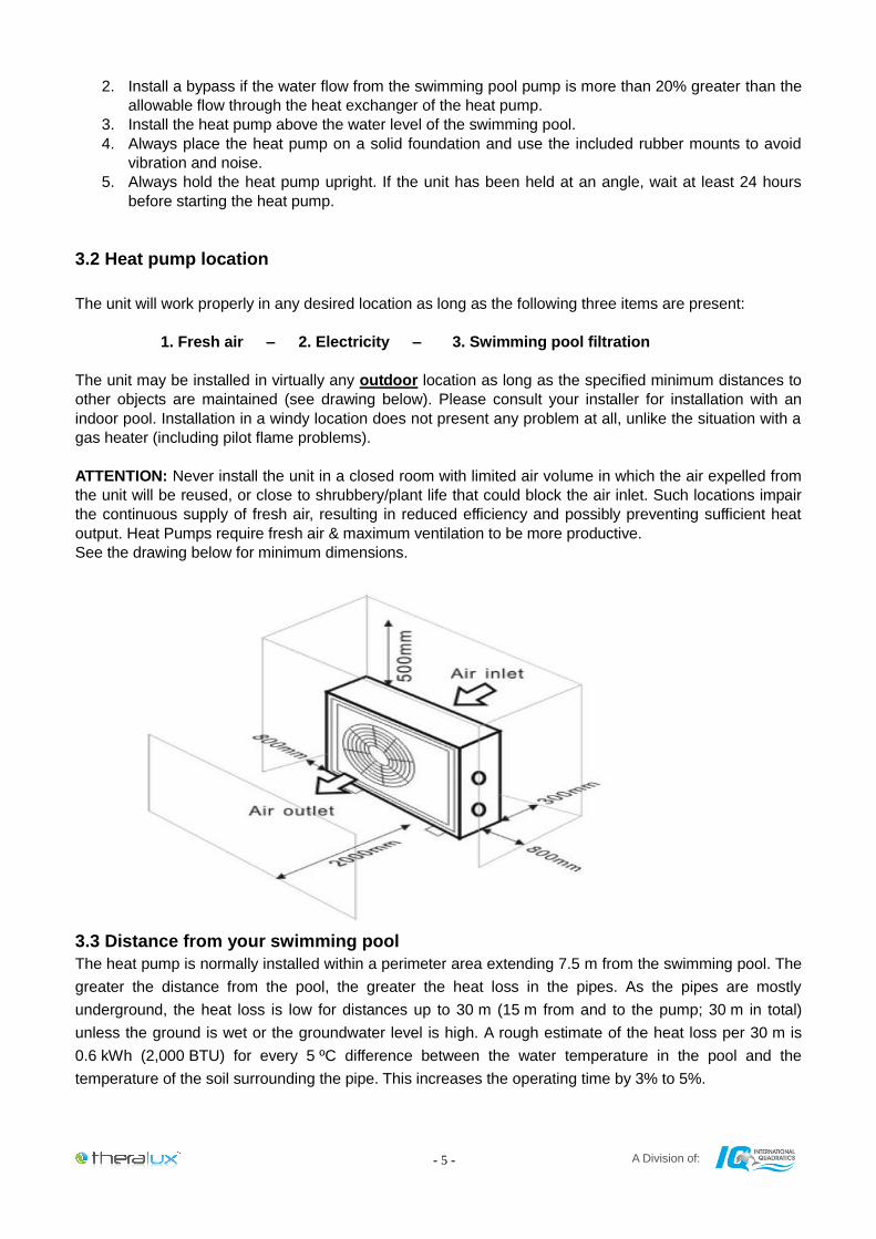
The unit may be installed in virtually any outdoor location as long as the specified minimum distances to
other objects are maintained (see drawing below). Please consult your installer for installation with an
indoor pool. Installation in a windy location does not present any problem at all, unlike the situation with a
gas heater (including pilot flame problems).
ATTENTION: Never install the unit in a closed room with limited air volume in which the air expelled from
the unit will be reused, or close to shrubbery/plant life that could block the air inlet. Such locations impair
the continuous supply of fresh air, resulting in reduced efficiency and possibly preventing sufficient heat
output. Heat Pumps require fresh air & maximum ventilation to be more productive.
See the drawing below for minimum dimensions.
3.3 Distance from your swimming pool
The heat pump is normally installed within a perimeter area extending 7.5 m from the swimming pool. The
greater the distance from the pool, the greater the heat loss in the pipes. As the pipes are mostly
underground, the heat loss is low for distances up to 30 m (15 m from and to the pump; 30 m in total)
unless the ground is wet or the groundwater level is high. A rough estimate of the heat loss per 30 m is
0.6 kWh (2,000 BTU) for every 5 ºC difference between the water temperature in the pool and the
temperature of the soil surrounding the pipe. This increases the operating time by 3% to 5%.
A Division of: - 6 -
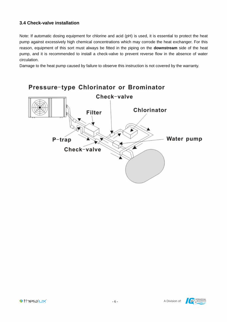
3.4 Check-valve installation
Note: If automatic dosing equipment for chlorine and acid (pH) is used, it is essential to protect the heat
pump against excessively high chemical concentrations which may corrode the heat exchanger. For this
reason, equipment of this sort must always be fitted in the piping on the downstream side of the heat
pump, and it is recommended to install a check-valve to prevent reverse flow in the absence of water
circulation.
Damage to the heat pump caused by failure to observe this instruction is not covered by the warranty.
A Division of: - 7 -
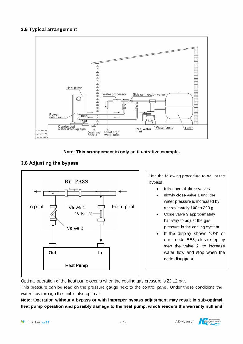
3.5 Typical arrangement
Note: This arrangement is only an illustrative example.
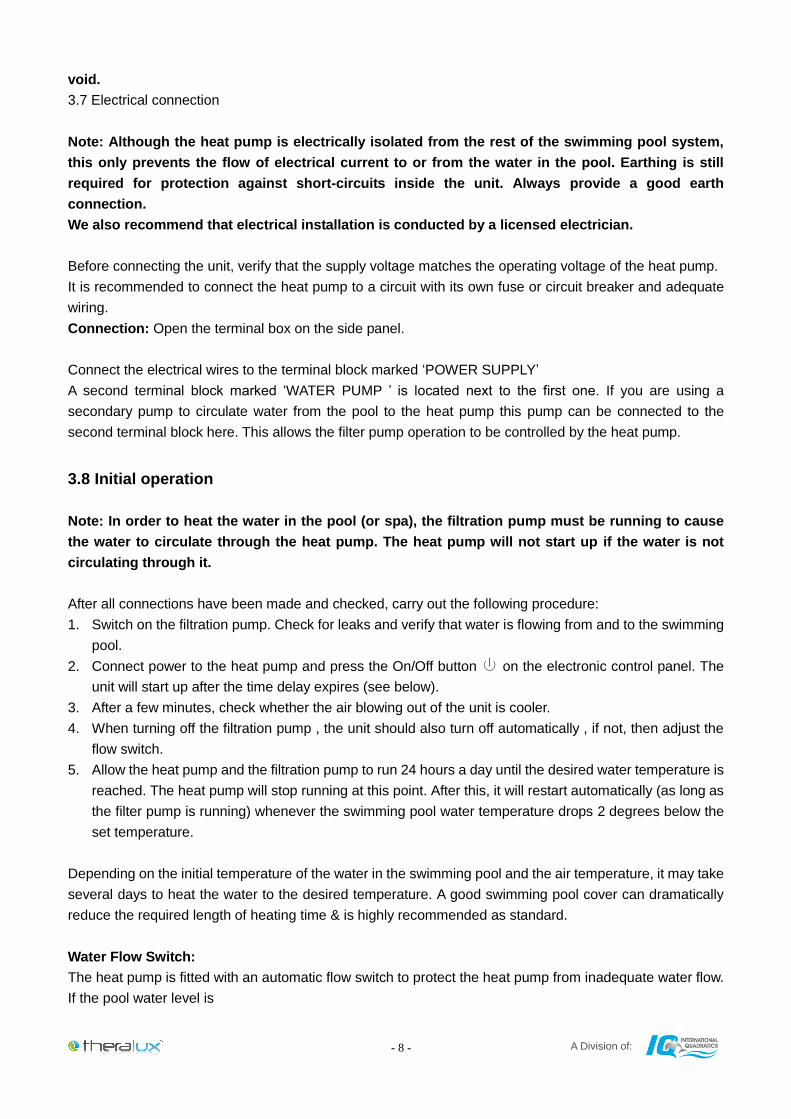
3.6 Adjusting the bypass
Optimal operation of the heat pump occurs when the cooling gas pressure is 22 2 bar.
This pressure can be read on the pressure gauge next to the control panel. Under these conditions the
water flow through the unit is also optimal.
Note: Operation without a bypass or with improper bypass adjustment may result in sub-optimal
heat pump operation and possibly damage to the heat pump, which renders the warranty null and
Out In
Heat Pump
Use the following procedure to adjust the
bypass:
fully open all three valves
slowly close valve 1 until the
water pressure is increased by
approximately 100 to 200 g
Close valve 3 approximately
half-way to adjust the gas
pressure in the cooling system
If the display shows "ON" or
error code EE3, close step by
step the valve 2, to increase
water flow and stop when the
code disappear.
To pool From pool
A Division of: - 8 -
void.
3.7 Electrical connection
Note: Although the heat pump is electrically isolated from the rest of the swimming pool system,
this only prevents the flow of electrical current to or from the water in the pool. Earthing is still
required for protection against short-circuits inside the unit. Always provide a good earth
connection.
We also recommend that electrical installation is conducted by a licensed electrician.
Before connecting the unit, verify that the supply voltage matches the operating voltage of the heat pump.
It is recommended to connect the heat pump to a circuit with its own fuse or circuit breaker and adequate
wiring.
Connection: Open the terminal box on the side panel.
Connect the electrical wires to the terminal block marked ‘POWER SUPPLY’
A second terminal block marked ‘WATER PUMP ’ is located next to the first one. If you are using a
secondary pump to circulate water from the pool to the heat pump this pump can be connected to the
second terminal block here. This allows the filter pump operation to be controlled by the heat pump.
3.8 Initial operation
Note: In order to heat the water in the pool (or spa), the filtration pump must be running to cause
the water to circulate through the heat pump. The heat pump will not start up if the water is not
circulating through it.
After all connections have been made and checked, carry out the following procedure:
1. Switch on the filtration pump. Check for leaks and verify that water is flowing from and to the swimming
pool.
2. Connect power to the heat pump and press the On/Off button on the electronic control panel. The
unit will start up after the time delay expires (see below).
3. After a few minutes, check whether the air blowing out of the unit is cooler.
4. When turning off the filtration pump , the unit should also turn off automatically , if not, then adjust the
flow switch.
5. Allow the heat pump and the filtration pump to run 24 hours a day until the desired water temperature is
reached. The heat pump will stop running at this point. After this, it will restart automatically (as long as
the filter pump is running) whenever the swimming pool water temperature drops 2 degrees below the
set temperature.
Depending on the initial temperature of the water in the swimming pool and the air temperature, it may take
several days to heat the water to the desired temperature. A good swimming pool cover can dramatically
reduce the required length of heating time & is highly recommended as standard.
Water Flow Switch:
The heat pump is fitted with an automatic flow switch to protect the heat pump from inadequate water flow.
If the pool water level is
A Division of: - 9 -
higher than 1m above or below the heat pump’s automatic adjustment knob, your dealer may need to
adjust its initial startup.
Time delay:
The heat pump has a built-in 3-minute start-up delay to protect the circuitry and avoid excessive contact
wear. The unit will restart automatically after this time delay expires. Even a brief power interruption will
trigger this time delay and prevent the unit from restarting immediately. Additional power interruptions
during this delay period do not affect the 3-minute duration of the delay.
3.9 Condensation
The air drawn into the heat pump is strongly cooled by the operation of the heat pump for heating the pool
water, this may cause condensation on the fins of the evaporator. The amount of condensation may be as
much as several litres per hour at high relative humidity. This is sometimes mistakenly regarded as a water
leak. If there is excessive water coming from your heat pump please see your installer.
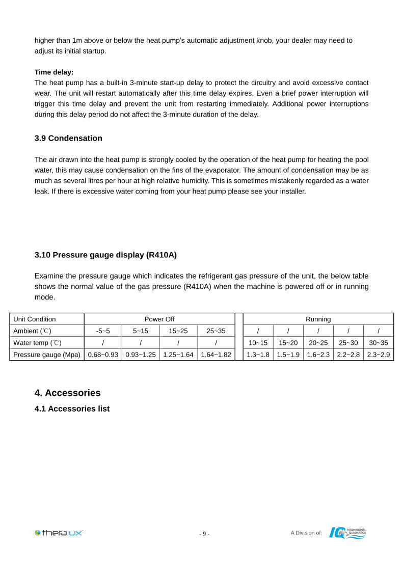
3.10 Pressure gauge display (R410A)
Examine the pressure gauge which indicates the refrigerant gas pressure of the unit, the below table
shows the normal value of the gas pressure (R410A) when the machine is powered off or in running
mode.
Unit Condition Power Off
Running
Ambient (℃) -5~5 5~15 15~25 25~35 / / / / /
Water temp (℃) / / / / 10~15 15~20 20~25 25~30 30~35
Pressure gauge (Mpa) 0.68~0.93 0.93~1.25 1.25~1.64 1.64~1.82 1.3~1.8 1.5~1.9 1.6~2.3 2.2~2.8 2.3~2.9
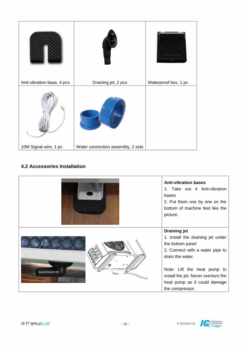
4. Accessories
4.1 Accessories list
A Division of: - 10 -
Anti-vibration base, 4 pcs
Draining jet, 2 pcs
Waterproof box, 1 pc
10M Signal wire, 1 pc
Water connection assembly, 2 sets
4.2 Accessories Installation
Anti-vibration bases
1. Take out 4 Anti-vibration
bases
2. Put them one by one on the
bottom of machine feet like the
picture.
Draining jet
1. Install the draining jet under
the bottom panel
2. Connect with a water pipe to
drain the water.
Note: Lift the heat pump to
install the jet. Never overturn the
heat pump as it could damage
the compressor.
A Division of: - 11 -
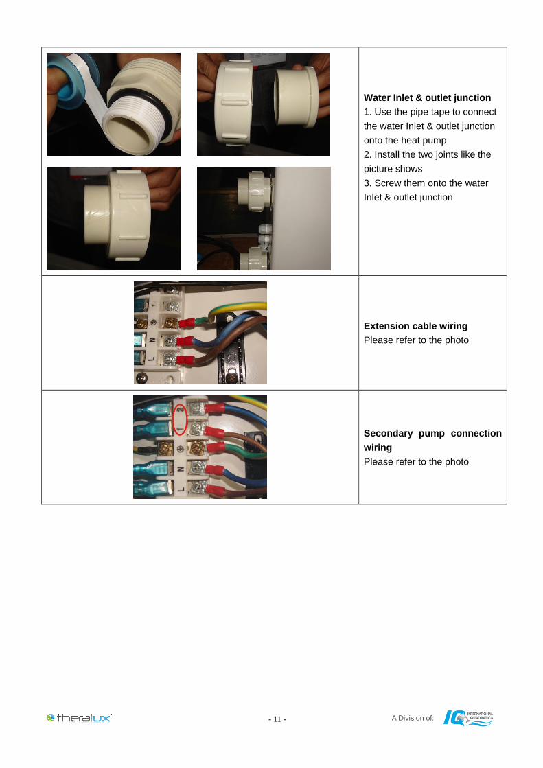
Water Inlet & outlet junction
1. Use the pipe tape to connect
the water Inlet & outlet junction
onto the heat pump
2. Install the two joints like the
picture shows
3. Screw them onto the water
Inlet & outlet junction
Extension cable wiring
Please refer to the photo
Secondary pump connection
wiring
Please refer to the photo
A Division of: - 12 -
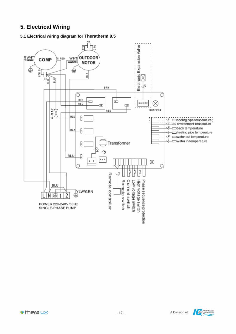
5. Electrical Wiring
5.1 Electrical wiring diagram for Theratherm 9.5
A Division of: - 13 -
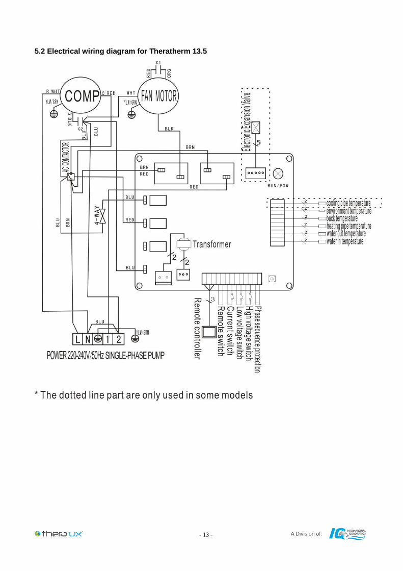
5.2 Electrical wiring diagram for Theratherm 13.5
A Division of: - 14 -
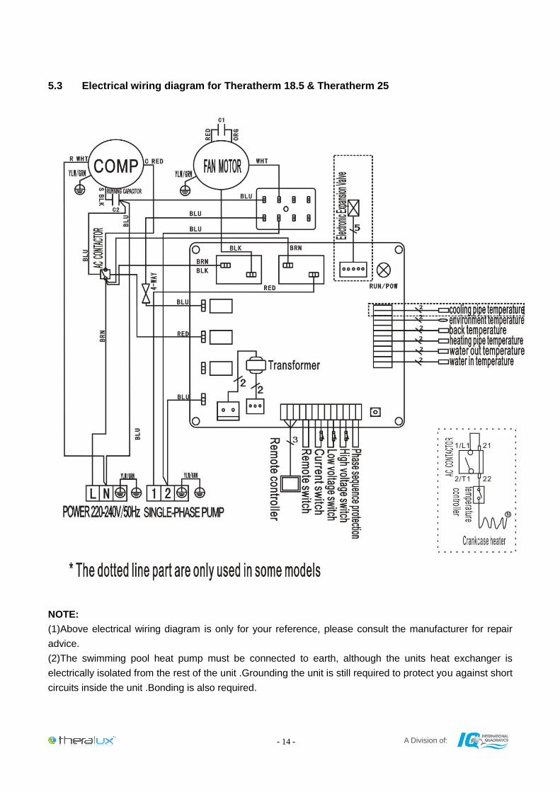
5.3 Electrical wiring diagram for Theratherm 18.5 & Theratherm 25
NOTE:
(1)Above electrical wiring diagram is only for your reference, please consult the manufacturer for repair
advice.
(2)The swimming pool heat pump must be connected to earth, although the units heat exchanger is
electrically isolated from the rest of the unit .Grounding the unit is still required to protect you against short
circuits inside the unit .Bonding is also required.
A Division of: - 15 -
Disconnect: A disconnect means (circuit breaker, fused or un-fused switch) should be located within sight
of and readily accessible from the unit .This is common practice on commercial and residential heat pumps.
It prevents remotely-energizing unattended equipment and permits turning off power at the unit while the
unit is being serviced.
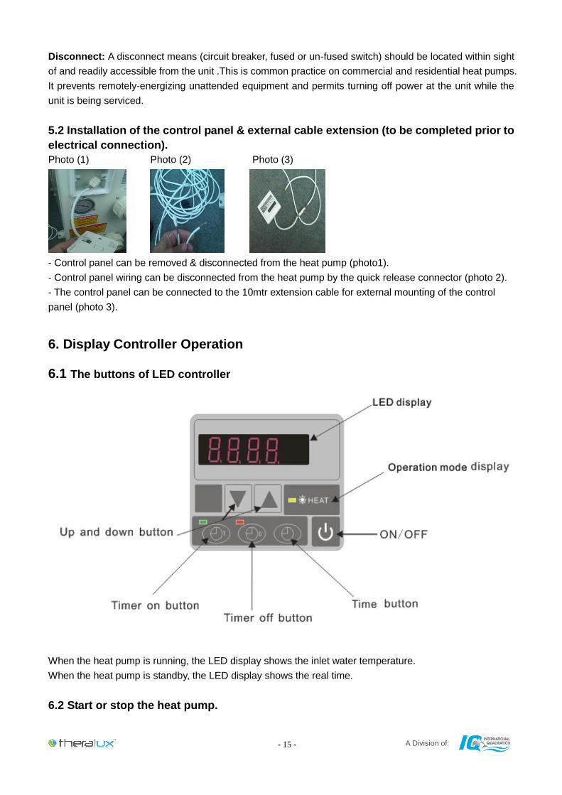
5.2 Installation of the control panel & external cable extension (to be completed prior to
electrical connection).
Photo (1) Photo (2) Photo (3)
- Control panel can be removed & disconnected from the heat pump (photo1).
- Control panel wiring can be disconnected from the heat pump by the quick release connector (photo 2).
- The control panel can be connected to the 10mtr extension cable for external mounting of the control
panel (photo 3).
6. Display Controller Operation
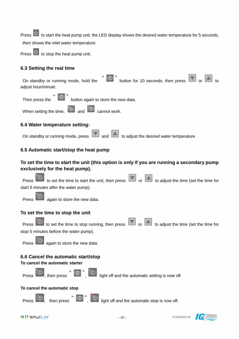
6.1 The buttons of LED controller
When the heat pump is running, the LED display shows the inlet water temperature.
When the heat pump is standby, the LED display shows the real time.
6.2 Start or stop the heat pump.
A Division of: - 16 -
Press to start the heat pump unit, the LED display shows the desired water temperature for 5 seconds,
then shows the inlet water temperature.
Press to stop the heat pump unit.
6.3 Setting the real time
On standby or running mode, hold the button for 10 seconds, then press or to
adjust hour/minute.
Then press the button again to store the new data.
When setting the time, and cannot work.
6.4 Water temperature setting:
On standby or running mode, press and to adjust the desired water temperature
6.5 Automatic start/stop the heat pump
To set the time to start the unit (this option is only if you are running a secondary pump
exclusively for the heat pump).
Press to set the time to start the unit, then press or to adjust the time (set the time for
start 5 minutes after the water pump).
Press again to store the new data.
To set the time to stop the unit
Press to set the time to stop running, then press or to adjust the time (set the time for
stop 5 minutes before the water pump).
Press again to store the new data.
6.6 Cancel the automatic start/stop
To cancel the automatic starter
Press , then press , light off and the automatic setting is now off.
To cancel the automatic stop
Press , then press , light off and the automatic stop is now off.
A Division of: - 17 -
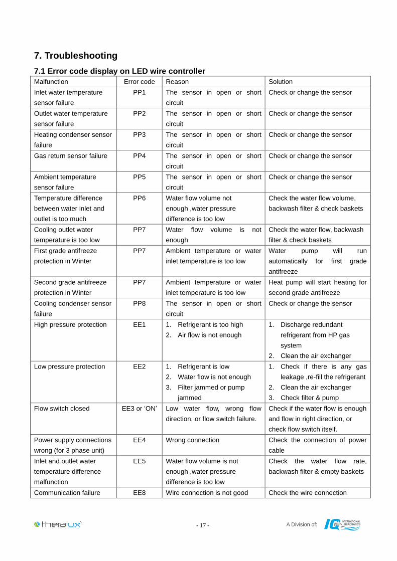
7. Troubleshooting
7.1 Error code display on LED wire controller
Malfunction Error code Reason Solution
Inlet water temperature
sensor failure
PP1 The sensor in open or short
circuit
Check or change the sensor
Outlet water temperature
sensor failure
PP2 The sensor in open or short
circuit
Check or change the sensor
Heating condenser sensor
failure
PP3 The sensor in open or short
circuit
Check or change the sensor
Gas return sensor failure PP4 The sensor in open or short
circuit
Check or change the sensor
Ambient temperature
sensor failure
PP5 The sensor in open or short
circuit
Check or change the sensor
Temperature difference
between water inlet and
outlet is too much
PP6 Water flow volume not
enough ,water pressure
difference is too low
Check the water flow volume,
backwash filter & check baskets
Cooling outlet water
temperature is too low
PP7 Water flow volume is not
enough
Check the water flow, backwash
filter & check baskets
First grade antifreeze
protection in Winter
PP7 Ambient temperature or water
inlet temperature is too low
Water pump will run
automatically for first grade
antifreeze
Second grade antifreeze
protection in Winter
PP7 Ambient temperature or water
inlet temperature is too low
Heat pump will start heating for
second grade antifreeze
Cooling condenser sensor
failure
PP8 The sensor in open or short
circuit
Check or change the sensor
High pressure protection EE1 1. Refrigerant is too high
2. Air flow is not enough
1. Discharge redundant
refrigerant from HP gas
system
2. Clean the air exchanger
Low pressure protection EE2 1. Refrigerant is low
2. Water flow is not enough
3. Filter jammed or pump
jammed
1. Check if there is any gas
leakage ,re-fill the refrigerant
2. Clean the air exchanger
3. Check filter & pump
Flow switch closed EE3 or ‘ON’ Low water flow, wrong flow
direction, or flow switch failure.
Check if the water flow is enough
and flow in right direction, or
check flow switch itself.
Power supply connections
wrong (for 3 phase unit)
EE4 Wrong connection Check the connection of power
cable
Inlet and outlet water
temperature difference
malfunction
EE5 Water flow volume is not
enough ,water pressure
difference is too low
Check the water flow rate,
backwash filter & empty baskets
Communication failure EE8 Wire connection is not good Check the wire connection
A Division of: - 18 -
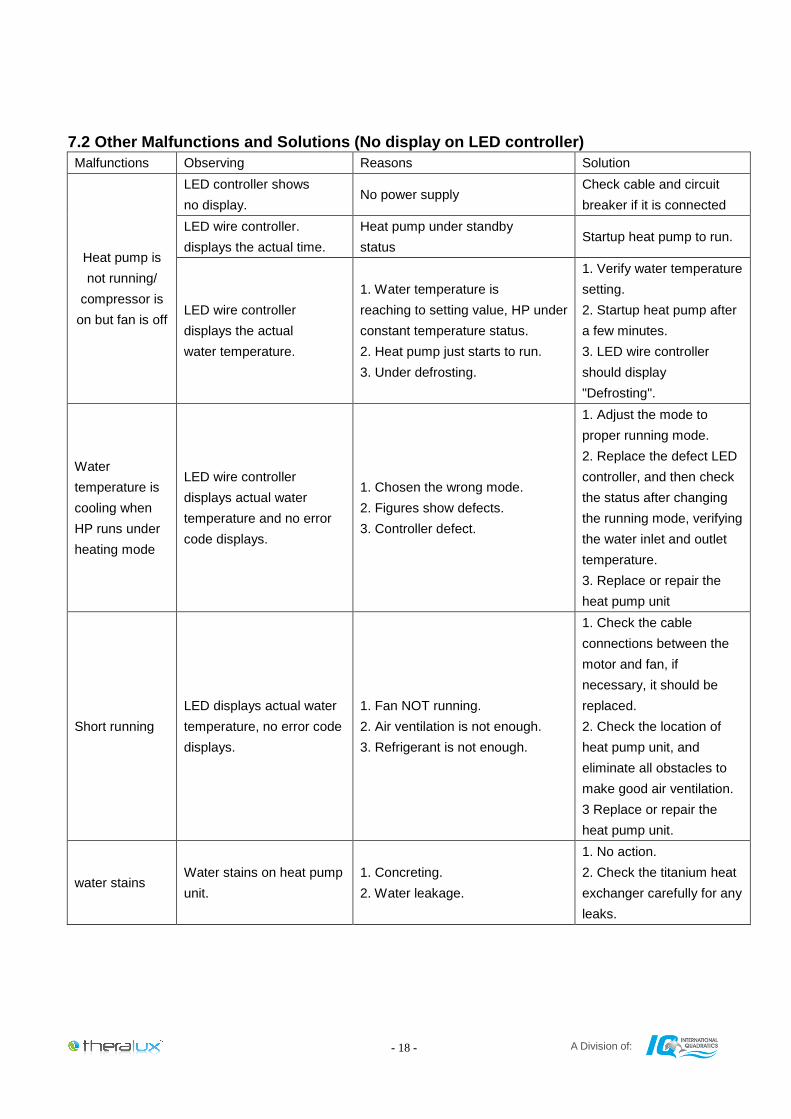
7.2 Other Malfunctions and Solutions (No display on LED controller)
Malfunctions Observing Reasons Solution
Heat pump is
not running/
compressor is
on but fan is off
LED controller shows
no display. No power supply
Check cable and circuit
breaker if it is connected
LED wire controller.
displays the actual time.
Heat pump under standby
status Startup heat pump to run.
LED wire controller
displays the actual
water temperature.
1. Water temperature is
reaching to setting value, HP under
constant temperature status.
2. Heat pump just starts to run.
3. Under defrosting.
1. Verify water temperature
setting.
2. Startup heat pump after
a few minutes.
3. LED wire controller
should display
"Defrosting".
Water
temperature is
cooling when
HP runs under
heating mode
LED wire controller
displays actual water
temperature and no error
code displays.
1. Chosen the wrong mode.
2. Figures show defects.
3. Controller defect.
1. Adjust the mode to
proper running mode.
2. Replace the defect LED
controller, and then check
the status after changing
the running mode, verifying
the water inlet and outlet
temperature.
3. Replace or repair the
heat pump unit
Short running
LED displays actual water
temperature, no error code
displays.
1. Fan NOT running.
2. Air ventilation is not enough.
3. Refrigerant is not enough.
1. Check the cable
connections between the
motor and fan, if
necessary, it should be
replaced.
2. Check the location of
heat pump unit, and
eliminate all obstacles to
make good air ventilation.
3 Replace or repair the
heat pump unit.
water stains Water stains on heat pump
unit.
1. Concreting.
2. Water leakage.
1. No action.
2. Check the titanium heat
exchanger carefully for any
leaks.
A Division of: - 19 -
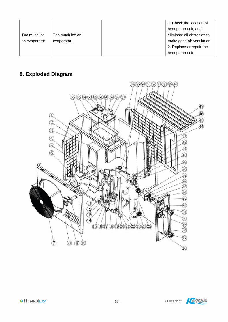
Too much ice
on evaporator
Too much ice on
evaporator.
1. Check the location of
heat pump unit, and
eliminate all obstacles to
make good air ventilation.
2. Replace or repair the
heat pump unit.
8. Exploded Diagram
A Division of: - 20 -
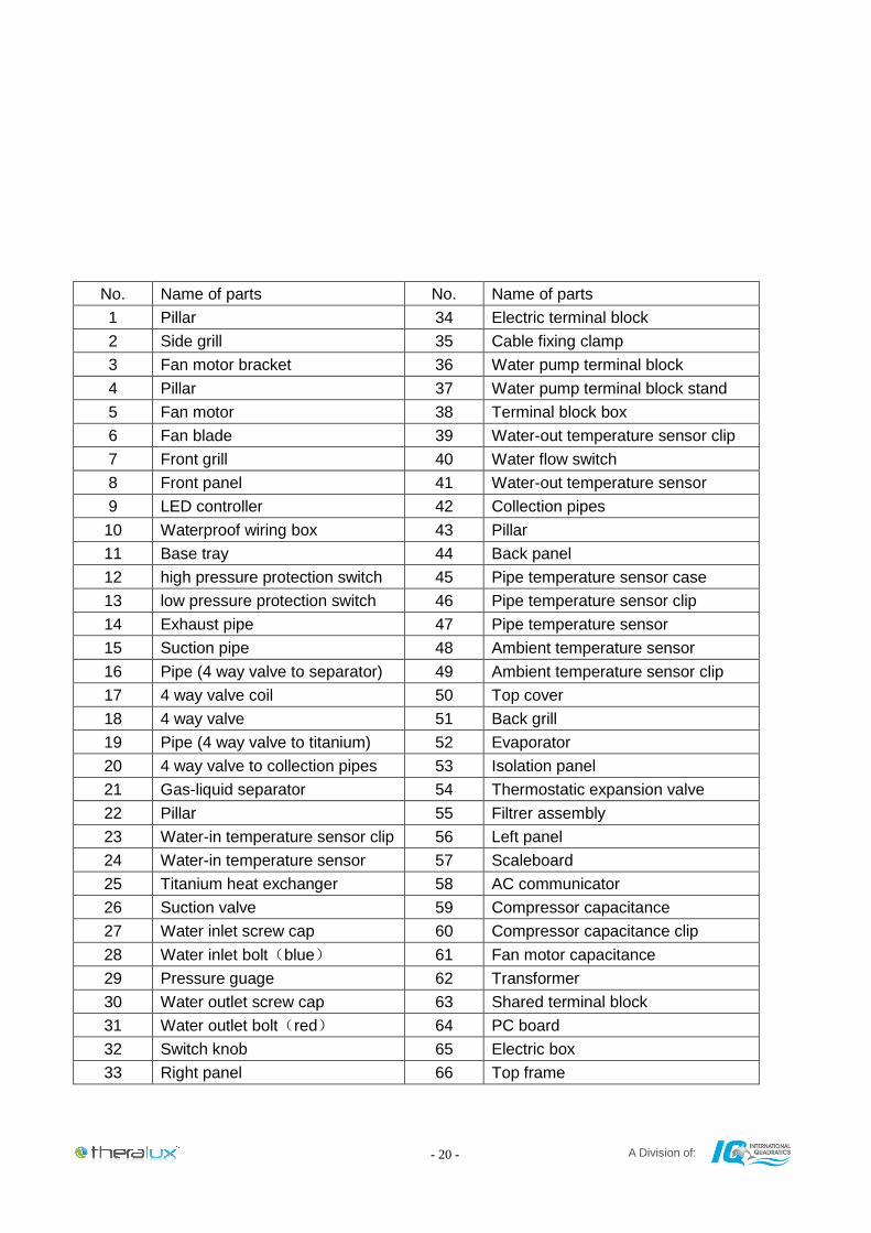
No. Name of parts No. Name of parts
1 Pillar 34 Electric terminal block
2 Side grill 35 Cable fixing clamp
3 Fan motor bracket 36 Water pump terminal block
4 Pillar 37 Water pump terminal block stand
5 Fan motor 38 Terminal block box
6 Fan blade 39 Water-out temperature sensor clip
7 Front grill 40 Water flow switch
8 Front panel 41 Water-out temperature sensor
9 LED controller 42 Collection pipes
10 Waterproof wiring box 43 Pillar
11 Base tray 44 Back panel
12 high pressure protection switch 45 Pipe temperature sensor case
13 low pressure protection switch 46 Pipe temperature sensor clip
14 Exhaust pipe 47 Pipe temperature sensor
15 Suction pipe 48 Ambient temperature sensor
16 Pipe (4 way valve to separator) 49 Ambient temperature sensor clip
17 4 way valve coil 50 Top cover
18 4 way valve 51 Back grill
19 Pipe (4 way valve to titanium) 52 Evaporator
20 4 way valve to collection pipes 53 Isolation panel
21 Gas-liquid separator 54 Thermostatic expansion valve
22 Pillar 55 Filtrer assembly
23 Water-in temperature sensor clip 56 Left panel
24 Water-in temperature sensor 57 Scaleboard
25 Titanium heat exchanger 58 AC communicator
26 Suction valve 59 Compressor capacitance
27 Water inlet screw cap 60 Compressor capacitance clip
28 Water inlet bolt(blue) 61 Fan motor capacitance
29 Pressure guage 62 Transformer
30 Water outlet screw cap 63 Shared terminal block
31 Water outlet bolt(red) 64 PC board
32 Switch knob 65 Electric box
33 Right panel 66 Top frame
A Division of: - 21 -
9. Maintenance
(1) You should check the water supply system regularly to avoid any air entering the system and
occurrence of low water flow, because it would reduce the performance and reliability of HP unit.
(2) Clean your pools and filtration system regularly to avoid damage of the unit as a result of a clogged/dirty
filter causing reduction in water flow.
(3) You should discharge the water from bottom of water pump if HP unit is intended to be shut down for a
long period (during the winter season).
(4) Upon start up after a long period of having the HP switched off, you should check the unit is full of water
before the unit starts to run again.
(5) When the unit is running, there will always be a little water discharge under the unit – this is normal.
11. Warranty
Theratherm Heat Pump warranty is a structured warranty. It particularly covers manufacturing faults & is
set out as below:
7 years on Titanium Heat Exchanger
7 years on scroll compressor
2 years on all other parts
Any faults with the Heat Pump resulting from incorrect installation, incorrect sizing, incorrect usage, neglect
of water chemistry or any other misuse will void the above stated warranty.
Please validate your warranty by visiting www.theralux.com.au and register your purchase. You can also
contact our customer service department via our website should you have any concerns.
Enjoy your new Theratherm Heated Swimming Pool.
From the team at,
Theralux.


