100790305, Rev. AJune 2016
Seagate® Nytro® XM1440PCIe® Gen 3 x4 - NVMe SSD
© 2016 Seagate Technology LLC. All rights reserved.Publication number: 100790305, Rev. A June 2016Seagate, Seagate Technology and the Spiral logo are registered trademarks of Seagate Technology LLC in the United States and/or other countries. Nytro and SeaTools are either trade-marks or registered trademarks of Seagate Technology LLC or one of its affiliated companies in the United States and/or other countries. The FIPS logo is a certification mark of NIST, which does not imply product endorsement by NIST, the U.S., or Canadian governments. All other trademarks or registered trademarks are the property of their respective owners.No part of this publication may be reproduced in any form without written permission of Seagate Technology LLC. Call 877-PUB-TEK1 (877-782-8351) to request permission.When referring to drive capacity, one gigabyte, or GB, equals one billion bytes and one terabyte, or TB, equals one trillion bytes. Your computer’s operating system may use a different standard of measurement and report a lower capacity. In addition, some of the listed capacity is used for formatting and other functions, and thus will not be available for data storage. Actual quantities will vary based on various factors, including file size, file format, features and application software. Actual data rates may vary depending on operating environment and other factors. The export or re-export of hardware or software containing encryption may be regulated by the U.S. Department of Commerce, Bureau of Industry and Security (for more information, visit www.bis.doc.gov), and controlled for import and use outside of the U.S. Seagate reserves the right to change, without notice, product offerings or specifications.
Document Revision History
Revision Date Pages affected and description of change
Rev. A June, 2016 Initial release.
Seagate XM1440 SSD Product Manual, Rev. A 2
Contents1.0 Scope . . . . . . . . . . . . . . . . . . . . . . . . . . . . . . . . . . . . . . . . . . . . . . . . . . . . . . . . . . . . . . . . . . . . . . . . . . . . . . . . . . . . . . . 4
2.0 Product Specifications. . . . . . . . . . . . . . . . . . . . . . . . . . . . . . . . . . . . . . . . . . . . . . . . . . . . . . . . . . . . . . . . . . . . . . . . 52.1 Models and Capacity . . . . . . . . . . . . . . . . . . . . . . . . . . . . . . . . . . . . . . . . . . . . . . . . . . . . . . . . . . . . . . . . . . . . . . . . . .52.2 Performance . . . . . . . . . . . . . . . . . . . . . . . . . . . . . . . . . . . . . . . . . . . . . . . . . . . . . . . . . . . . . . . . . . . . . . . . . . . . . . . . . .52.3 Power Consumption . . . . . . . . . . . . . . . . . . . . . . . . . . . . . . . . . . . . . . . . . . . . . . . . . . . . . . . . . . . . . . . . . . . . . . . . . .62.4 Power Loss Data Protection. . . . . . . . . . . . . . . . . . . . . . . . . . . . . . . . . . . . . . . . . . . . . . . . . . . . . . . . . . . . . . . . . . . .62.5 Out of Band Management (SMBus). . . . . . . . . . . . . . . . . . . . . . . . . . . . . . . . . . . . . . . . . . . . . . . . . . . . . . . . . . . . .62.6 Basic Management Command . . . . . . . . . . . . . . . . . . . . . . . . . . . . . . . . . . . . . . . . . . . . . . . . . . . . . . . . . . . . . . . . .62.7 Environmental Conditions . . . . . . . . . . . . . . . . . . . . . . . . . . . . . . . . . . . . . . . . . . . . . . . . . . . . . . . . . . . . . . . . . . . . .82.8 Reliability . . . . . . . . . . . . . . . . . . . . . . . . . . . . . . . . . . . . . . . . . . . . . . . . . . . . . . . . . . . . . . . . . . . . . . . . . . . . . . . . . . . . .92.9 Endurance . . . . . . . . . . . . . . . . . . . . . . . . . . . . . . . . . . . . . . . . . . . . . . . . . . . . . . . . . . . . . . . . . . . . . . . . . . . . . . . . . . . .9
3.0 Mechanical Information . . . . . . . . . . . . . . . . . . . . . . . . . . . . . . . . . . . . . . . . . . . . . . . . . . . . . . . . . . . . . . . . . . . . . 103.1 M.2 Mechanical Dimensions and Weight . . . . . . . . . . . . . . . . . . . . . . . . . . . . . . . . . . . . . . . . . . . . . . . . . . . . . .10
3.1.1 M.2 Device Plug Descriptions. . . . . . . . . . . . . . . . . . . . . . . . . . . . . . . . . . . . . . . . . . . . . . . . . . . . . . .113.1.2 SMBus Pin-out . . . . . . . . . . . . . . . . . . . . . . . . . . . . . . . . . . . . . . . . . . . . . . . . . . . . . . . . . . . . . . . . . . . . .11
4.0 Interface requirements . . . . . . . . . . . . . . . . . . . . . . . . . . . . . . . . . . . . . . . . . . . . . . . . . . . . . . . . . . . . . . . . . . . . . . 134.1 PCIe features . . . . . . . . . . . . . . . . . . . . . . . . . . . . . . . . . . . . . . . . . . . . . . . . . . . . . . . . . . . . . . . . . . . . . . . . . . . . . . . . .134.2 Interface Commands Supported: . . . . . . . . . . . . . . . . . . . . . . . . . . . . . . . . . . . . . . . . . . . . . . . . . . . . . . . . . . . . .134.3 Log Page Support . . . . . . . . . . . . . . . . . . . . . . . . . . . . . . . . . . . . . . . . . . . . . . . . . . . . . . . . . . . . . . . . . . . . . . . . . . . .144.4 SMART Attributes . . . . . . . . . . . . . . . . . . . . . . . . . . . . . . . . . . . . . . . . . . . . . . . . . . . . . . . . . . . . . . . . . . . . . . . . . . . .15
5.0 Standards and Reference Documents. . . . . . . . . . . . . . . . . . . . . . . . . . . . . . . . . . . . . . . . . . . . . . . . . . . . . . . . . 175.1 Standards . . . . . . . . . . . . . . . . . . . . . . . . . . . . . . . . . . . . . . . . . . . . . . . . . . . . . . . . . . . . . . . . . . . . . . . . . . . . . . . . . . . .17
5.1.1 Electromagnetic compatibility. . . . . . . . . . . . . . . . . . . . . . . . . . . . . . . . . . . . . . . . . . . . . . . . . . . . . .175.1.2 Electromagnetic compliance . . . . . . . . . . . . . . . . . . . . . . . . . . . . . . . . . . . . . . . . . . . . . . . . . . . . . . .175.1.3 Electromagnetic compliance for the European Union . . . . . . . . . . . . . . . . . . . . . . . . . . . . . . .175.1.4 Canada ICES-003 . . . . . . . . . . . . . . . . . . . . . . . . . . . . . . . . . . . . . . . . . . . . . . . . . . . . . . . . . . . . . . . . . . .175.1.5 Australian RCM Mark . . . . . . . . . . . . . . . . . . . . . . . . . . . . . . . . . . . . . . . . . . . . . . . . . . . . . . . . . . . . . . .175.1.6 Korean KCC . . . . . . . . . . . . . . . . . . . . . . . . . . . . . . . . . . . . . . . . . . . . . . . . . . . . . . . . . . . . . . . . . . . . . . . .185.1.7 Taiwanese BSMI. . . . . . . . . . . . . . . . . . . . . . . . . . . . . . . . . . . . . . . . . . . . . . . . . . . . . . . . . . . . . . . . . . . .185.1.8 European Union Restriction of Hazardous Substances (RoHS). . . . . . . . . . . . . . . . . . . . . . . .185.1.9 China Restriction of Hazardous Substances (RoHS) Directive. . . . . . . . . . . . . . . . . . . . . . . . .18
5.2 Reference Documents and Support . . . . . . . . . . . . . . . . . . . . . . . . . . . . . . . . . . . . . . . . . . . . . . . . . . . . . . . . . . .19
Seagate XM1440 SSD Product Manual, Rev. A 3
Figures
Figure 1. M.2 device plug dimensions . . . . . . . . . . . . . . . . . . . . . . . . . . . . . . . . . . . . . . . . . . . . . . . . . . . . . . . . . . . . . . . . . . . . . 10Figure 2. M.2 device plug dimension (detail) . . . . . . . . . . . . . . . . . . . . . . . . . . . . . . . . . . . . . . . . . . . . . . . . . . . . . . . . . . . . . . 11
Seagate XM1440 SSD Product Manual, Rev. A 4
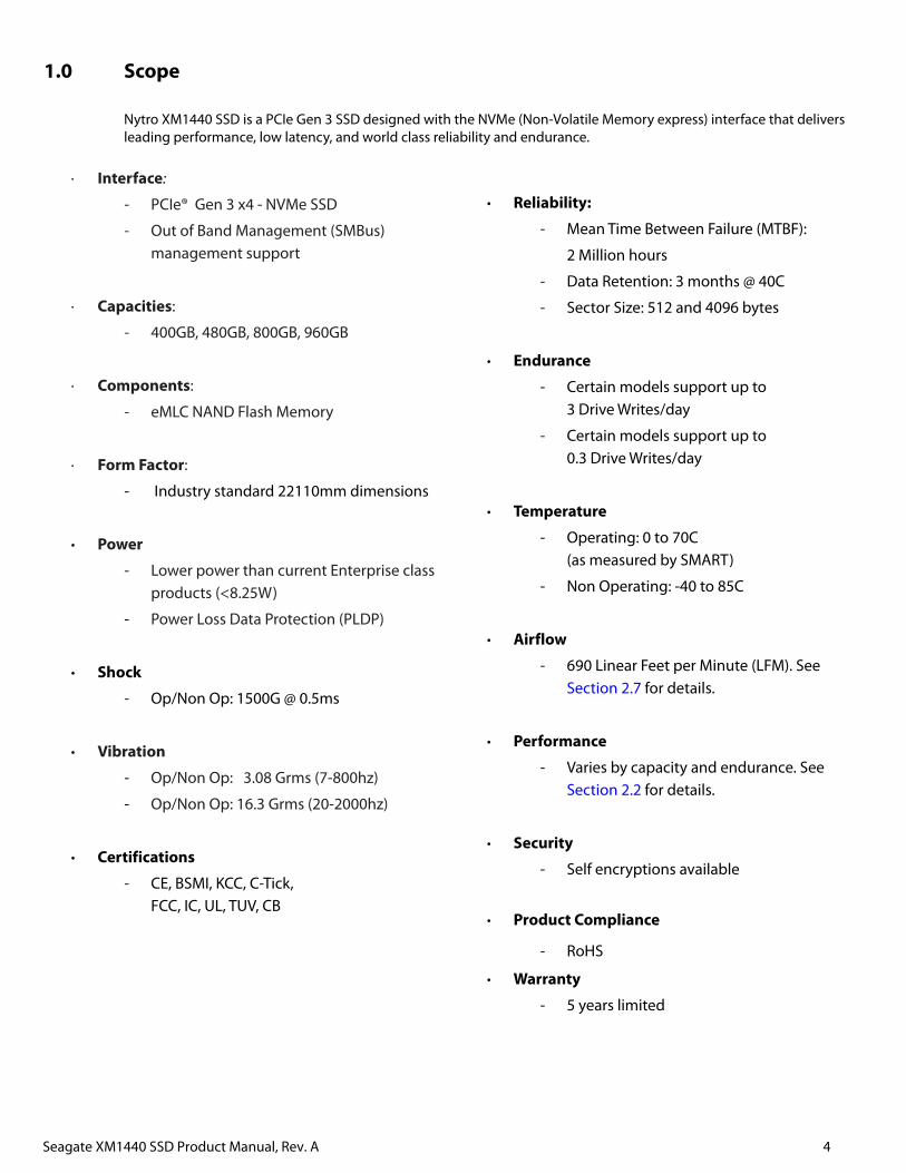
1.0 Scope
Nytro XM1440 SSD is a PCIe Gen 3 SSD designed with the NVMe (Non-Volatile Memory express) interface that delivers leading performance, low latency, and world class reliability and endurance.
· Interface:
PCIe® Gen 3 x4 - NVMe SSD
Out of Band Management (SMBus) management support
· Capacities:
400GB, 480GB, 800GB, 960GB
· Components:
eMLC NAND Flash Memory
· Form Factor:
Industry standard 22110mm dimensions
· Power
Lower power than current Enterprise class products (<8.25W)
Power Loss Data Protection (PLDP)
· Shock
Op/Non Op: 1500G @ 0.5ms
· Vibration
Op/Non Op: 3.08 Grms (7-800hz)
Op/Non Op: 16.3 Grms (20-2000hz)
· Certifications
CE, BSMI, KCC, C-Tick, FCC, IC, UL, TUV, CB
· Reliability:
Mean Time Between Failure (MTBF):
2 Million hours
Data Retention: 3 months @ 40C
Sector Size: 512 and 4096 bytes
· Endurance
Certain models support up to 3 Drive Writes/day
Certain models support up to 0.3 Drive Writes/day
· Temperature
Operating: 0 to 70C (as measured by SMART)
Non Operating: -40 to 85C
· Airflow
690 Linear Feet per Minute (LFM). See Section 2.7 for details.
· Performance
Varies by capacity and endurance. See Section 2.2 for details.
· Security
Self encryptions available
· Product Compliance
RoHS
· Warranty
5 years limited
Seagate XM1440 SSD Product Manual, Rev. A 5
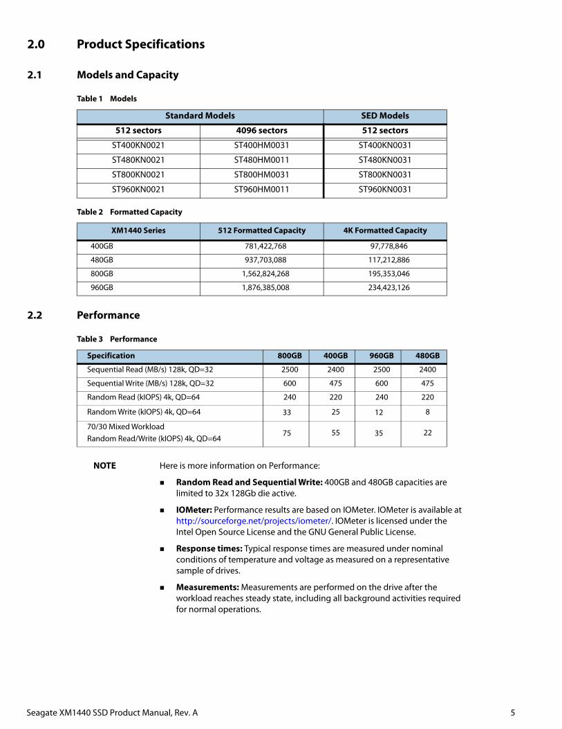
2.0 Product Specifications
2.1 Models and Capacity
2.2 Performance
NOTE Here is more information on Performance:
Random Read and Sequential Write: 400GB and 480GB capacities are limited to 32x 128Gb die active.
IOMeter: Performance results are based on IOMeter. IOMeter is available at http://sourceforge.net/projects/iometer/. IOMeter is licensed under the Intel Open Source License and the GNU General Public License.
Response times: Typical response times are measured under nominal conditions of temperature and voltage as measured on a representative sample of drives.
Measurements: Measurements are performed on the drive after the workload reaches steady state, including all background activities required for normal operations.
Table 1 Models
Standard Models SED Models
512 sectors 4096 sectors 512 sectors
ST400KN0021 ST400HM0031 ST400KN0031
ST480KN0021 ST480HM0011 ST480KN0031
ST800KN0021 ST800HM0031 ST800KN0031
ST960KN0021 ST960HM0011 ST960KN0031
Table 2 Formatted Capacity
XM1440 Series 512 Formatted Capacity 4K Formatted Capacity
400GB 781,422,768 97,778,846
480GB 937,703,088 117,212,886
800GB 1,562,824,268 195,353,046
960GB 1,876,385,008 234,423,126
Table 3 Performance
Specification 800GB 400GB 960GB 480GB
Sequential Read (MB/s) 128k, QD=32 2500 2400 2500 2400
Sequential Write (MB/s) 128k, QD=32 600 475 600 475
Random Read (kIOPS) 4k, QD=64 240 220 240 220
Random Write (kIOPS) 4k, QD=64 33 25 12 8
70/30 Mixed WorkloadRandom Read/Write (kIOPS) 4k, QD=64
75 55 35 22
Seagate XM1440 SSD Product Manual, Rev. A 6
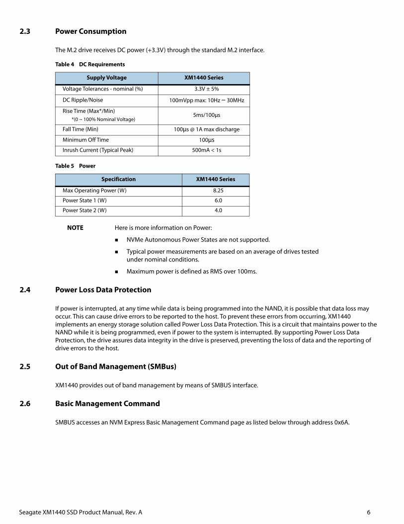
2.3 Power Consumption
The M.2 drive receives DC power (+3.3V) through the standard M.2 interface.
NOTE Here is more information on Power:
NVMe Autonomous Power States are not supported.
Typical power measurements are based on an average of drives tested under nominal conditions.
Maximum power is defined as RMS over 100ms.
2.4 Power Loss Data Protection
If power is interrupted, at any time while data is being programmed into the NAND, it is possible that data loss may occur. This can cause drive errors to be reported to the host. To prevent these errors from occurring, XM1440 implements an energy storage solution called Power Loss Data Protection. This is a circuit that maintains power to the NAND while it is being programmed, even if power to the system is interrupted. By supporting Power Loss Data Protection, the drive assures data integrity in the drive is preserved, preventing the loss of data and the reporting of drive errors to the host.
2.5 Out of Band Management (SMBus)
XM1440 provides out of band management by means of SMBUS interface.
2.6 Basic Management Command
SMBUS accesses an NVM Express Basic Management Command page as listed below through address 0x6A.
Table 4 DC Requirements
Supply Voltage XM1440 Series
Voltage Tolerances - nominal (%) 3.3V ± 5%
DC Ripple/Noise 100mVpp max: 10Hz – 30MHz
Rise Time (Max*/Min)*(0 ~ 100% Nominal Voltage)
5ms/100μs
Fall Time (Min) 100μs @ 1A max discharge
Minimum Off Time 100μs
Inrush Current (Typical Peak) 500mA < 1s
Table 5 Power
Specification XM1440 Series
Max Operating Power (W) 8.25
Power State 1 (W) 6.0
Power State 2 (W) 4.0
Seagate XM1440 SSD Product Manual, Rev. A 7
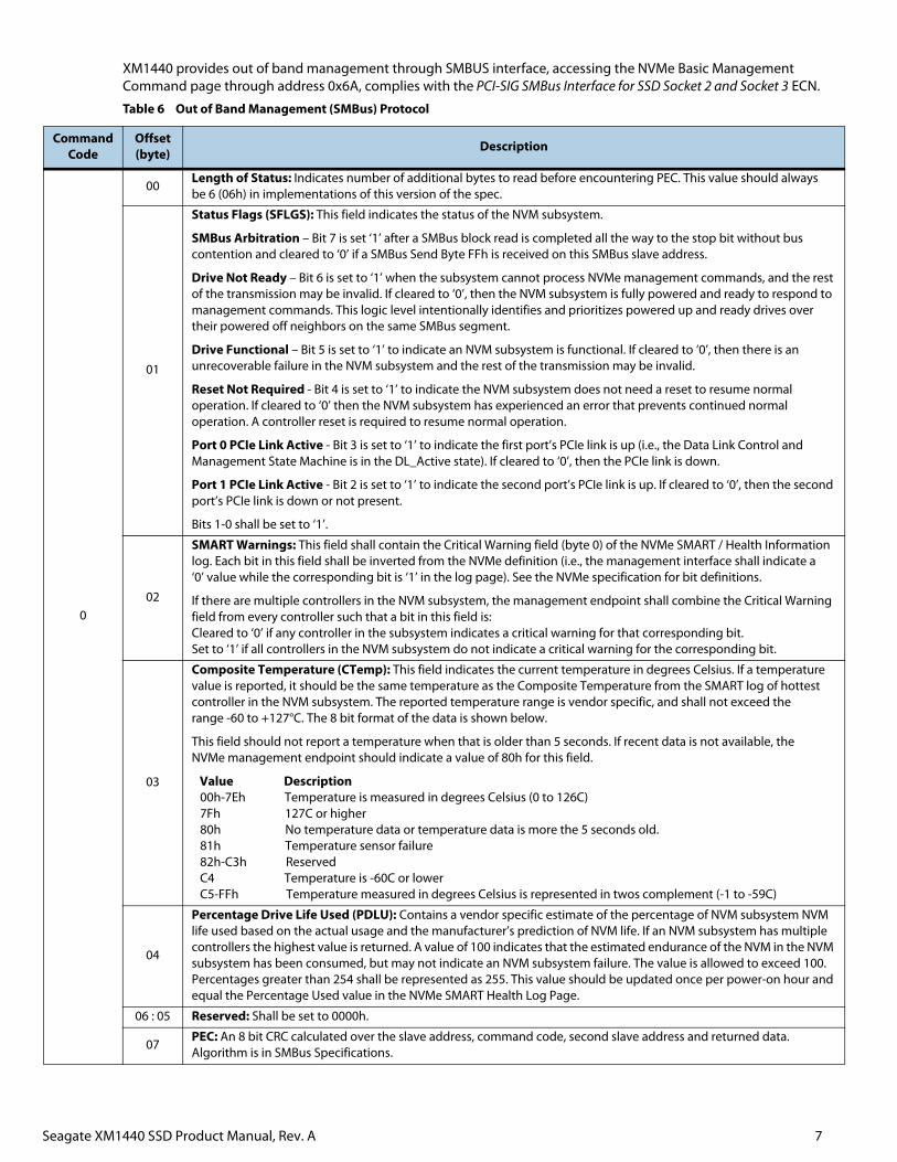
XM1440 provides out of band management through SMBUS interface, accessing the NVMe Basic Management Command page through address 0x6A, complies with the PCI-SIG SMBus Interface for SSD Socket 2 and Socket 3 ECN.
Table 6 Out of Band Management (SMBus) Protocol
CommandCode
Offset(byte) Description
0
00Length of Status: Indicates number of additional bytes to read before encountering PEC. This value should always be 6 (06h) in implementations of this version of the spec.
01
Status Flags (SFLGS): This field indicates the status of the NVM subsystem.
SMBus Arbitration – Bit 7 is set ‘1’ after a SMBus block read is completed all the way to the stop bit without bus contention and cleared to ‘0’ if a SMBus Send Byte FFh is received on this SMBus slave address.
Drive Not Ready – Bit 6 is set to ‘1’ when the subsystem cannot process NVMe management commands, and the rest of the transmission may be invalid. If cleared to ‘0’, then the NVM subsystem is fully powered and ready to respond to management commands. This logic level intentionally identifies and prioritizes powered up and ready drives over their powered off neighbors on the same SMBus segment.
Drive Functional – Bit 5 is set to ‘1’ to indicate an NVM subsystem is functional. If cleared to ‘0’, then there is an unrecoverable failure in the NVM subsystem and the rest of the transmission may be invalid.
Reset Not Required - Bit 4 is set to ‘1’ to indicate the NVM subsystem does not need a reset to resume normal operation. If cleared to ‘0’ then the NVM subsystem has experienced an error that prevents continued normal operation. A controller reset is required to resume normal operation.
Port 0 PCIe Link Active - Bit 3 is set to ‘1’ to indicate the first port’s PCIe link is up (i.e., the Data Link Control and Management State Machine is in the DL_Active state). If cleared to ‘0’, then the PCIe link is down.
Port 1 PCIe Link Active - Bit 2 is set to ‘1’ to indicate the second port’s PCIe link is up. If cleared to ‘0’, then the second port’s PCIe link is down or not present.
Bits 1-0 shall be set to ‘1’.
02
SMART Warnings: This field shall contain the Critical Warning field (byte 0) of the NVMe SMART / Health Information log. Each bit in this field shall be inverted from the NVMe definition (i.e., the management interface shall indicate a ‘0’ value while the corresponding bit is ‘1’ in the log page). See the NVMe specification for bit definitions.
If there are multiple controllers in the NVM subsystem, the management endpoint shall combine the Critical Warning field from every controller such that a bit in this field is:Cleared to ‘0’ if any controller in the subsystem indicates a critical warning for that corresponding bit.Set to ‘1’ if all controllers in the NVM subsystem do not indicate a critical warning for the corresponding bit.
03
Composite Temperature (CTemp): This field indicates the current temperature in degrees Celsius. If a temperature value is reported, it should be the same temperature as the Composite Temperature from the SMART log of hottest controller in the NVM subsystem. The reported temperature range is vendor specific, and shall not exceed the range -60 to +127°C. The 8 bit format of the data is shown below.
This field should not report a temperature when that is older than 5 seconds. If recent data is not available, the NVMe management endpoint should indicate a value of 80h for this field.
Value Description 00h-7Eh Temperature is measured in degrees Celsius (0 to 126C) 7Fh 127C or higher 80h No temperature data or temperature data is more the 5 seconds old. 81h Temperature sensor failure 82h-C3h Reserved C4 Temperature is -60C or lower C5-FFh Temperature measured in degrees Celsius is represented in twos complement (-1 to -59C)
04
Percentage Drive Life Used (PDLU): Contains a vendor specific estimate of the percentage of NVM subsystem NVM life used based on the actual usage and the manufacturer’s prediction of NVM life. If an NVM subsystem has multiple controllers the highest value is returned. A value of 100 indicates that the estimated endurance of the NVM in the NVM subsystem has been consumed, but may not indicate an NVM subsystem failure. The value is allowed to exceed 100. Percentages greater than 254 shall be represented as 255. This value should be updated once per power-on hour and equal the Percentage Used value in the NVMe SMART Health Log Page.
06 : 05 Reserved: Shall be set to 0000h.
07PEC: An 8 bit CRC calculated over the slave address, command code, second slave address and returned data. Algorithm is in SMBus Specifications.
Seagate XM1440 SSD Product Manual, Rev. A 8
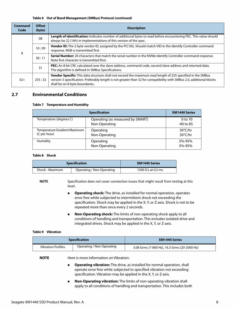
2.7 Environmental Conditions
NOTE Specification does not cover connection issues that might result from testing at this level.
Operating shock: The drive, as installed for normal operation, operates error free while subjected to intermittent shock not exceeding the specification. Shock may be applied in the X, Y, or Z-axis. Shock is not to be repeated more than once every 2 seconds.
Non-Operating shock: The limits of non-operating shock apply to all conditions of handling and transportation. This includes isolated drive and integrated drives. Shock may be applied in the X, Y, or Z-axis.
NOTE Here is more information on Vibration:
Operating vibration: The drive, as installed for normal operation, shall operate error free while subjected to specified vibration not exceeding specification. Vibration may be applied in the X, Y, or Z-axis.
Non-Operating vibration: The limits of non-operating vibration shall apply to all conditions of handling and transportation. This includes both
8
08Length of identification: Indicates number of additional bytes to read before encountering PEC. This value should always be 22 (16h) in implementations of this version of the spec.
10 : 09Vendor ID: The 2 byte vendor ID, assigned by the PCI SIG. Should match VID in the Identify Controller command response. MSB is transmitted first.
30 : 11Serial Number: 20 characters that match the serial number in the NVMe Identify Controller command response. Note first character is transmitted first.
31PEC: An 8 bit CRC calculated over the slave address, command code, second slave address and returned data. The algorithm is defined in SMBus Specifications.
32+ 255 : 32Vendor Specific: This data structure shall not exceed the maximum read length of 255 specified in the SMBus version 3 specification. Preferably length is not greater than 32 for compatibility with SMBus 2.0, additional blocks shall be on 8 byte boundaries.
Table 7 Temperature and Humidity
Specification XM1440 Series
Temperature (degrees C) Operating (as measured by SMART) Non-Operating
0 to 70-40 to 85
Temperature Gradient Maximum (C per hour)
Operating Non-Operating
30°C/hr30°C/hr
Humidity Operating Non-Operating
5%-95%5%-95%
Table 8 Shock
Specification XM1440 Series
Shock - Maximum Operating / Non Operating 1500 G's at 0.5 ms
Table 9 Vibration
Specification XM1440 Series
Vibration Profiles Operating / Non Operating 3.08 Grms (7-800 Hz), 16.3 Grms (20-2000 Hz)
Table 6 Out of Band Management (SMBus) Protocol (continued)
CommandCode
Offset(byte) Description
Seagate XM1440 SSD Product Manual, Rev. A 9
isolated drive and integrated drives. Vibration may be applied in the X, Y, or Z-axis.
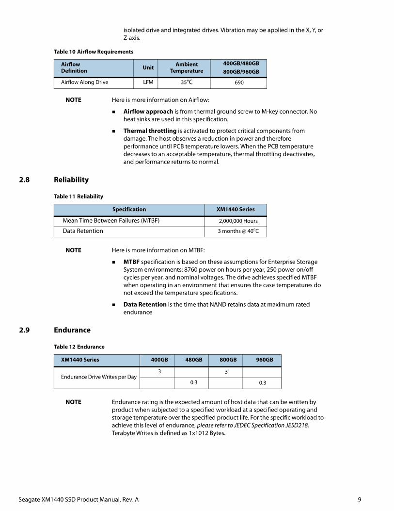
NOTE Here is more information on Airflow:
Airflow approach is from thermal ground screw to M-key connector. No heat sinks are used in this specification.
Thermal throttling is activated to protect critical components from damage. The host observes a reduction in power and therefore performance until PCB temperature lowers. When the PCB temperature decreases to an acceptable temperature, thermal throttling deactivates, and performance returns to normal.
2.8 Reliability
NOTE Here is more information on MTBF:
MTBF specification is based on these assumptions for Enterprise Storage System environments: 8760 power on hours per year, 250 power on/off cycles per year, and nominal voltages. The drive achieves specified MTBF when operating in an environment that ensures the case temperatures do not exceed the temperature specifications.
Data Retention is the time that NAND retains data at maximum rated endurance
2.9 Endurance
NOTE Endurance rating is the expected amount of host data that can be written by product when subjected to a specified workload at a specified operating and storage temperature over the specified product life. For the specific workload to achieve this level of endurance, please refer to JEDEC Specification JESD218. Terabyte Writes is defined as 1x10¹² Bytes.
Table 10 Airflow Requirements
Airflow Definition Unit Ambient
Temperature400GB/480GB800GB/960GB
Airflow Along Drive LFM 35°C 690
Table 11 Reliability
Specification XM1440 Series
Mean Time Between Failures (MTBF) 2,000,000 Hours
Data Retention 3 months @ 40°C
Table 12 Endurance
XM1440 Series 400GB 480GB 800GB 960GB
Endurance Drive Writes per Day 3 3
0.3 0.3
Seagate XM1440 SSD Product Manual, Rev. A 10
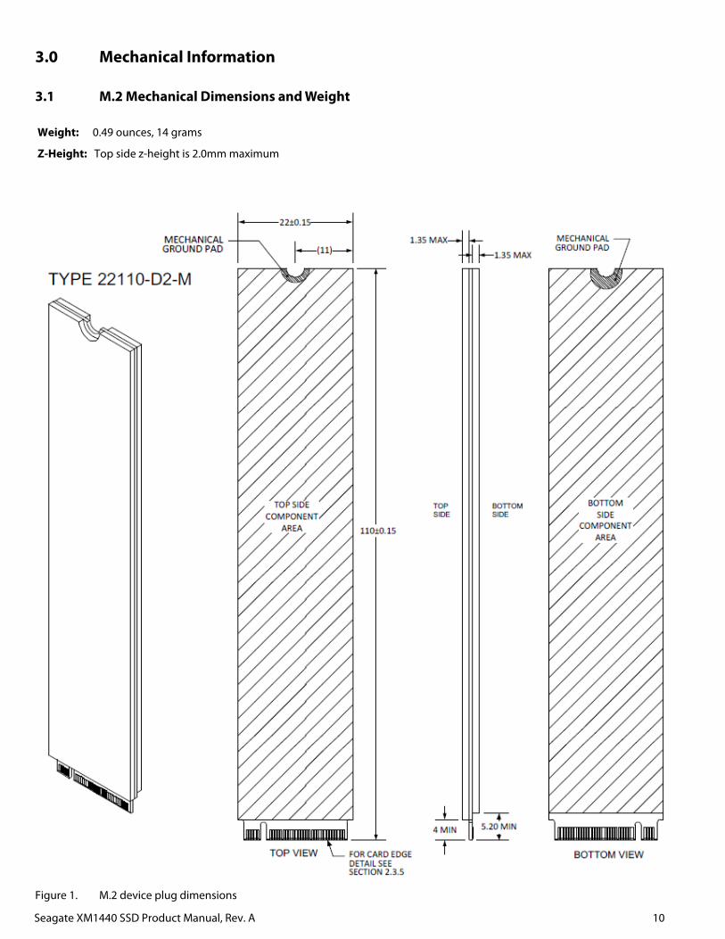
3.0 Mechanical Information
3.1 M.2 Mechanical Dimensions and Weight
Figure 1. M.2 device plug dimensions
Weight: 0.49 ounces, 14 grams
Z-Height: Top side z-height is 2.0mm maximum
Seagate XM1440 SSD Product Manual, Rev. A 11
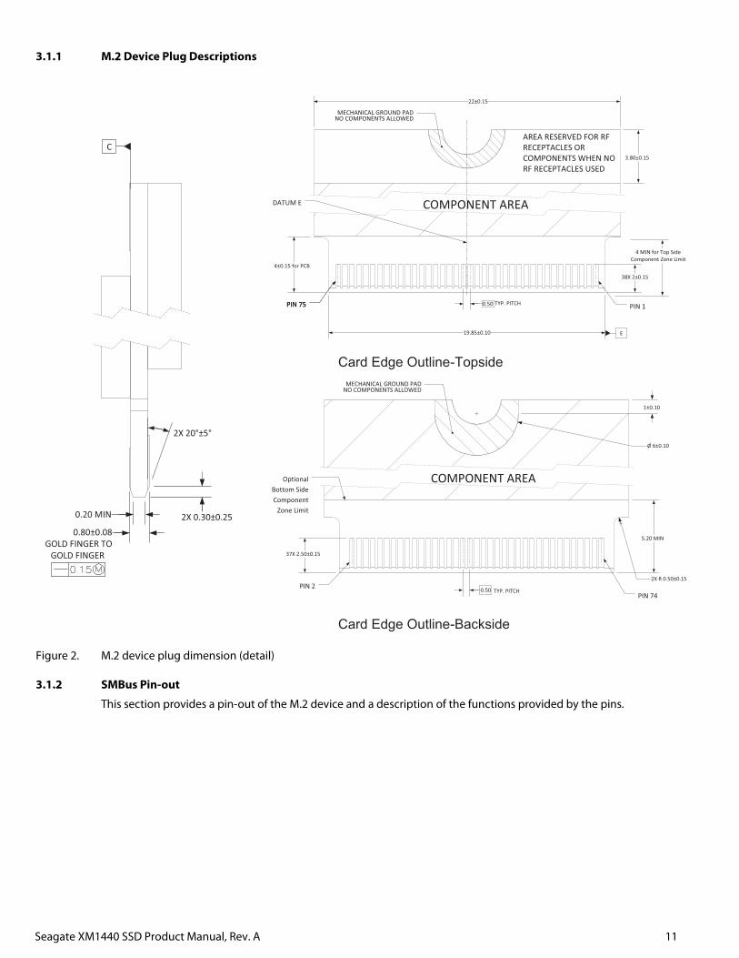
3.1.1 M.2 Device Plug Descriptions
Figure 2. M.2 device plug dimension (detail)
3.1.2 SMBus Pin-out
This section provides a pin-out of the M.2 device and a description of the functions provided by the pins.
C
2X 0.30±0.250.80±0.08
GOLD FINGER TOGOLD FINGER
2X 20°±5°
0.20 MIN
4 MIN for Top Side Component Zone Limit
COMPONENT AREA
MECHANICAL GROUND PADNO COMPONENTS ALLOWED
19.85±0.10
3.80±0.15
22±0.15
38X 2±0.15
4±0.15 for PCB
TYP. PITCH0.50PIN 75PIN 75 PIN 1
AREA RESERVED FOR RFRECEPTACLES ORCOMPONENTS WHEN NORF RECEPTACLES USED
E
DATUM E
Card Edge Outline-Topside
COMPONENT AREA
MECHANICAL GROUND PADNO COMPONENTS ALLOWED
5.20 MIN
37X 2.50±0.15
PIN 2PIN 74
TYP. PITCH0.50
OptionalBottom SideComponent
Zone Limit
1±0.10
Ø 6±0.10
2X R 0.50±0.15
Card Edge Outline-Backside
Seagate XM1440 SSD Product Manual, Rev. A 12
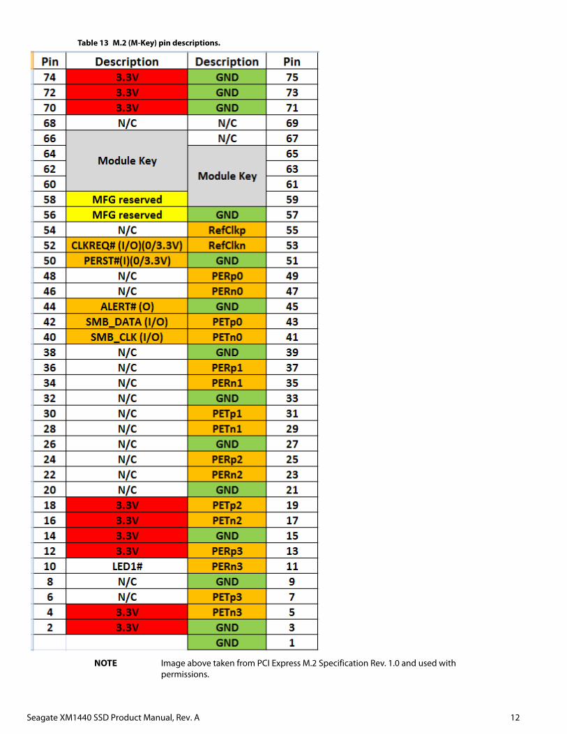
Table 13 M.2 (M-Key) pin descriptions.
NOTE Image above taken from PCI Express M.2 Specification Rev. 1.0 and used with permissions.
Seagate XM1440 SSD Product Manual, Rev. A 13
4.0 Interface requirements
4.1 PCIe features
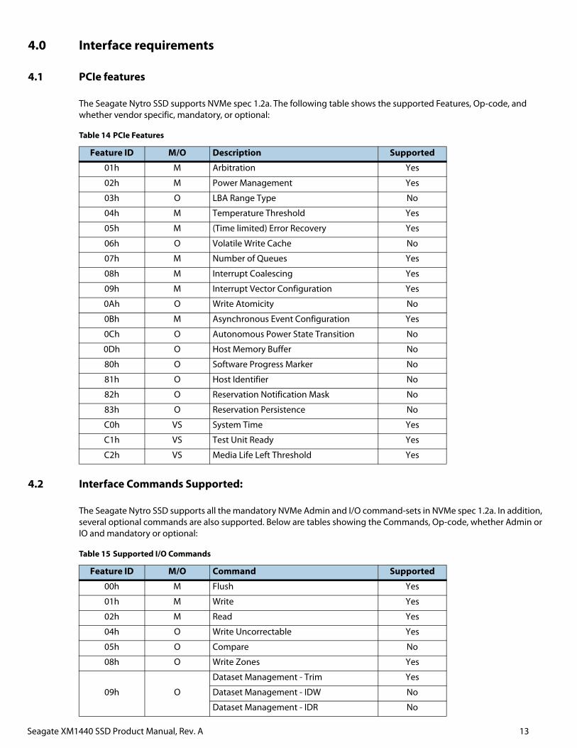
The Seagate Nytro SSD supports NVMe spec 1.2a. The following table shows the supported Features, Op-code, and whether vendor specific, mandatory, or optional:
4.2 Interface Commands Supported:
The Seagate Nytro SSD supports all the mandatory NVMe Admin and I/O command-sets in NVMe spec 1.2a. In addition, several optional commands are also supported. Below are tables showing the Commands, Op-code, whether Admin or IO and mandatory or optional:
Table 14 PCIe Features
Feature ID M/O Description Supported
01h M Arbitration Yes
02h M Power Management Yes
03h O LBA Range Type No
04h M Temperature Threshold Yes
05h M (Time limited) Error Recovery Yes
06h O Volatile Write Cache No
07h M Number of Queues Yes
08h M Interrupt Coalescing Yes
09h M Interrupt Vector Configuration Yes
0Ah O Write Atomicity No
0Bh M Asynchronous Event Configuration Yes
0Ch O Autonomous Power State Transition No
0Dh O Host Memory Buffer No
80h O Software Progress Marker No
81h O Host Identifier No
82h O Reservation Notification Mask No
83h O Reservation Persistence No
C0h VS System Time Yes
C1h VS Test Unit Ready Yes
C2h VS Media Life Left Threshold Yes
Table 15 Supported I/O Commands
Feature ID M/O Command Supported
00h M Flush Yes
01h M Write Yes
02h M Read Yes
04h O Write Uncorrectable Yes
05h O Compare No
08h O Write Zones Yes
09h O
Dataset Management - Trim Yes
Dataset Management - IDW No
Dataset Management - IDR No
Seagate XM1440 SSD Product Manual, Rev. A 14
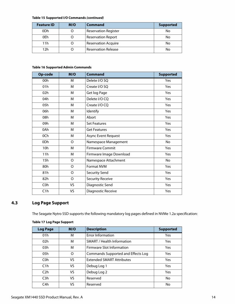
4.3 Log Page Support
The Seagate Nytro SSD supports the following mandatory log pages defined in NVMe 1.2a specification:
0Dh O Reservation Register No
0Eh O Reservation Report No
11h O Reservation Acquire No
12h O Reservation Release No
Table 16 Supported Admin Commands
Op-code M/O Command Supported
00h M Delete I/O SQ Yes
01h M Create I/O SQ Yes
02h M Get log Page Yes
04h M Delete I/O CQ Yes
05h M Create I/O CQ Yes
06h M Identify Yes
08h M Abort Yes
09h M Set Features Yes
0Ah M Get Features Yes
0Ch M Async Event Request Yes
0Dh O Namespace Management No
10h M Firmware Commit Yes
11h M Firmware Image Download Yes
15h O Namespace Attachment No
80h O Format NVM Yes
81h O Security Send Yes
82h O Security Receive Yes
C0h VS Diagnostic Send Yes
C1h VS Diagnostic Receive Yes
Table 17 Log Page Support
Log Page M/O Description Supported
01h M Error Information Yes
02h M SMART / Health Information Yes
03h M Firmware Slot Information Yes
05h O Commands Supported and Effects Log Yes
C0h VS Extended SMART Attributes Yes
C1h VS Debug Log 1 Yes
C2h VS Debug Log 2 Yes
C3h VS Reserved No
C4h VS Reserved No
Table 15 Supported I/O Commands (continued)
Feature ID M/O Command Supported
Seagate XM1440 SSD Product Manual, Rev. A 15
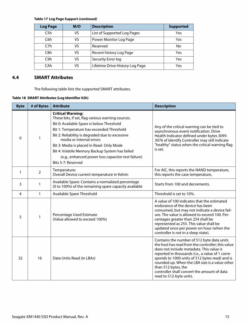
4.4 SMART Attributes
The following table lists the supported SMART attributes.
C5h VS List of Supported Log Pages Yes
C6h VS Power Monitor Log Page Yes
C7h VS Reserved No
C8h VS Recent history Log Page Yes
C9h VS Security Error log Yes
CAh VS Lifetime Drive History Log Page Yes
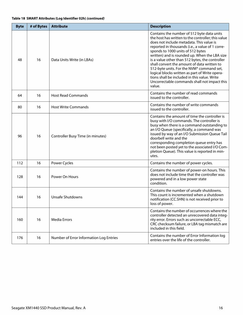
Table 18 SMART Attributes (Log Identifier 02h)
Byte # of Bytes Attribute Description
0 1
Critical Warning: These bits, if set, flag various warning sources.Bit 0: Available Spare is below ThresholdBit 1: Temperature has exceeded ThresholdBit 2: Reliability is degraded due to excessive media or internal errorsBit 3: Media is placed in Read- Only ModeBit 4: Volatile Memory Backup System has failed (e.g., enhanced power loss capacitor test failure)Bits 5-7: Reserved
Any of the critical warning can be tied to asynchronous event notification. Drive Health Indicator defined under bytes 3095- 3076 of Identify Controller may still indicate "healthy" status when the critical warning flag is set.
1 2 Temperature: Overall Device current temperature in Kelvin
For AIC, this reports the NAND temperature, this reports the case temperature,
3 1 Available Spare: Contains a normalized percentage (0 to 100%) of the remaining spare capacity available Starts from 100 and decrements.
4 1 Available Spare Threshold Threshold is set to 10%.
5 1 Percentage Used Estimate (Value allowed to exceed 100%)
A value of 100 indicates that the estimated endurance of the device has been consumed, but may not indicate a device fail-ure. The value is allowed to exceed 100. Per-centages greater than 254 shall be represented as 255. This value shall be updated once per power-on hour (when the controller is not in a sleep state).
32 16 Data Units Read (in LBAs)
Contains the number of 512 byte data units the host has read from the controller; this value does not include metadata. This value is reported in thousands (i.e., a value of 1 corre-sponds to 1000 units of 512 bytes read) and is rounded up. When the LBA size is a value other than 512 bytes, the controller shall convert the amount of data read to 512-byte units.
Table 17 Log Page Support (continued)
Log Page M/O Description Supported
Seagate XM1440 SSD Product Manual, Rev. A 16
48 16 Data Units Write (in LBAs)
Contains the number of 512 byte data units the host has written to the controller; this value does not include metadata. This value is reported in thousands (i.e., a value of 1 corre-sponds to 1000 units of 512 bytes written) and is rounded up. When the LBA size is a value other than 512 bytes, the controller shall convert the amount of data written to 512-byte units. For the NVM* command set, logical blocks written as part of Write opera-tions shall be included in this value. Write Uncorrectable commands shall not impact this value.
64 16 Host Read Commands Contains the number of read commands issued to the controller.
80 16 Host Write Commands Contains the number of write commands issued to the controller.
96 16 Controller Busy Time (in minutes)
Contains the amount of time the controller is busy with I/O commands. The controller is busy when there is a command outstanding to an I/O Queue (specifically, a command was issued by way of an I/O Submission Queue Tail doorbell write and the corresponding completion queue entry has not been posted yet to the associated I/O Com-pletion Queue). This value is reported in min-utes.
112 16 Power Cycles Contains the number of power cycles.
128 16 Power On Hours
Contains the number of power-on hours. This does not include time that the controller was powered and in a low power state condition.
144 16 Unsafe Shutdowns
Contains the number of unsafe shutdowns. This count is incremented when a shutdown notification (CC.SHN) is not received prior to loss of power.
160 16 Media Errors
Contains the number of occurrences where the controller detected an unrecovered data integ-rity error. Errors such as uncorrectable ECC, CRC checksum failure, or LBA tag mismatch are included in this field.
176 16 Number of Error Information Log Entries Contains the number of Error Information log entries over the life of the controller.
Table 18 SMART Attributes (Log Identifier 02h) (continued)
Byte # of Bytes Attribute Description
Seagate XM1440 SSD Product Manual, Rev. A 17
5.0 Standards and Reference Documents
5.1 Standards
The Seagate® Nytro® XM1440 family complies with Seagate standards as noted in the appropriate sections of this manual.
The drives are recognized in accordance with UL 60950-1 as tested by UL, CSA 60950-1 as tested by CSA, and EN60950-1 as tested by TUV.
The security features of Self-Encrypting Drive models are based on the “TCG Storage Architecture Core Specification” and the “Storage Work Group Storage Security Subsystem Class: Opal, Version 2.00”.
5.1.1 Electromagnetic compatibility
The drive, as delivered, is designed for system integration and installation into a suitable enclosure prior to use. The drive is supplied as a subassembly and is not subject to Subpart B of Part 15 of the FCC Rules and Regulations nor the Radio Interference Regulations of the Canadian Department of Communications.
The design characteristics of the drive serve to minimize radiation when installed in an enclosure that provides reasonable shielding. The drive is capable of meeting the Class B limits of the FCC Rules and Regulations of the Canadian Department of Communications when properly packaged; however, it is the user’s responsibility to assure that the drive meets the appropriate EMI requirements in their system. Shielded I/O cables may be required if the enclosure does not provide adequate shielding. If the I/O cables are external to the enclosure, shielded cables should be used, with the shields grounded to the enclosure and to the host controller.
5.1.1.1 Electromagnetic susceptibility
As a component assembly, the drive is not required to meet any susceptibility performance requirements. It is the responsibility of those integrating the drive within their systems to perform those tests required and design their system to ensure that equipment operating in the same system as the drive or external to the system does not adversely affect the performance of the drive.
5.1.2 Electromagnetic compliance
Seagate uses an independent laboratory to confirm compliance with the directives/standards for CE Marking and C-Tick Marking. The drive was tested in a representative system for typical applications and comply with the Electromagnetic Interference/Electromagnetic Susceptibility (EMI/EMS) for Class B products. The selected system represents the most popular characteristics for test platforms. The system configurations include:
Typical current use microprocessor
Keyboard
Monitor/display
Printer
Mouse
Although the test system with this Seagate model complies with the directives/standards, we cannot guarantee that all systems will comply. The computer manufacturer or system integrator shall confirm EMC compliance and provide the appropriate marking for their product.
5.1.3 Electromagnetic compliance for the European Union
If this model has the CE Marking it complies with the European Union requirements of the Electromagnetic Compatibility Directive 2004/108/EC as put into place on 20 July 2007.
5.1.4 Canada ICES-003
If this model has the ICES-003 Marking it complies with the Canadian Standard Association Standard CAN/CSA-CISPR 22-10, Information Technology Equipment - Radio Disturbance Characteristics - Limits and Methods of Measurement.
5.1.5 Australian RCM Mark
If this model has the RCM Marking it complies with the Australia/New Zealand Standard AS/NZ CISPR22 and meets the Electromagnetic Compatibility (EMC) Framework requirements of Australia’s Radiocommunications Act.
Seagate XM1440 SSD Product Manual, Rev. A 18
5.1.6 Korean KCC
If these drives have the Korean Communications Commission (KCC) logo, they comply with KN22, KN 24, and KN61000.
5.1.7 Taiwanese BSMI
If this model has two Chinese words meaning “EMC certification” followed by an eight digit identification number, as a Marking, it complies with Chinese National Standard (CNS) 13438 and meets the Electromagnetic Compatibility (EMC) Framework requirements of the Taiwanese Bureau of Standards, Metrology, and Inspection (BSMI).
5.1.8 European Union Restriction of Hazardous Substances (RoHS)
The European Union Restriction of Hazardous Substances (RoHS) Directive restricts the presence of chemical substances, including Lead (Pb), in electronic products effective July 2006.
A number of parts and materials in Seagate products are procured from external suppliers. We rely on the representations of our suppliers regarding the presence of RoHS substances in these parts and materials. Our supplier contracts require compliance with our chemical substance restrictions, and our suppliers document their compliance with our requirements by providing material content declarations for all parts and materials for the disk drives documented in this publication. Current supplier declarations include disclosure of the inclusion of any RoHS-regulated substance in such parts or materials.
Seagate also has internal systems in place to ensure ongoing compliance with the RoHS Directive and all laws and regulations which restrict chemical content in electronic products. These systems include standard operating procedures that ensure that restricted substances are not utilized in our manufacturing operations, laboratory analytical validation testing, and an internal auditing process to ensure that all standard operating procedures are complied with.
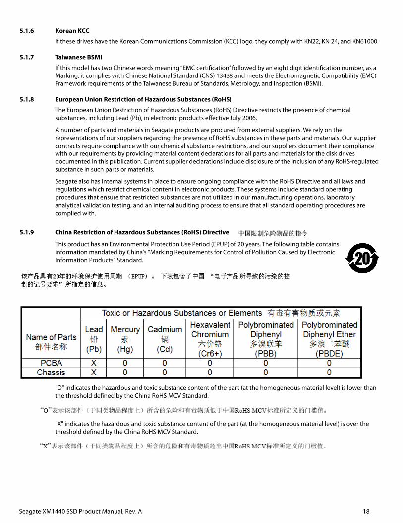
5.1.9 China Restriction of Hazardous Substances (RoHS) Directive
This product has an Environmental Protection Use Period (EPUP) of 20 years. The following table contains information mandated by China's "Marking Requirements for Control of Pollution Caused by Electronic Information Products" Standard.
"O" indicates the hazardous and toxic substance content of the part (at the homogeneous material level) is lower than the threshold defined by the China RoHS MCV Standard.
"X" indicates the hazardous and toxic substance content of the part (at the homogeneous material level) is over the threshold defined by the China RoHS MCV Standard.
Seagate XM1440 SSD Product Manual, Rev. A 19
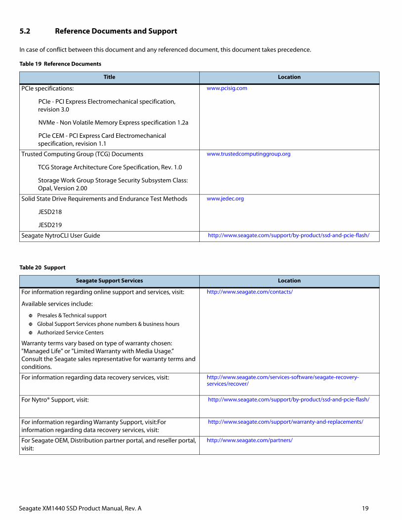
5.2 Reference Documents and Support
In case of conflict between this document and any referenced document, this document takes precedence.
Table 19 Reference Documents
Title Location
PCIe specifications:
PCIe - PCI Express Electromechanical specification, revision 3.0
NVMe - Non Volatile Memory Express specification 1.2a
PCIe CEM - PCI Express Card Electromechanical specification, revision 1.1
www.pcisig.com
Trusted Computing Group (TCG) Documents
TCG Storage Architecture Core Specification, Rev. 1.0
Storage Work Group Storage Security Subsystem Class: Opal, Version 2.00
www.trustedcomputinggroup.org
Solid State Drive Requirements and Endurance Test Methods
JESD218
JESD219
www.jedec.org
Seagate NytroCLI User Guide http://www.seagate.com/support/by-product/ssd-and-pcie-flash/
Table 20 Support
Seagate Support Services Location
For information regarding online support and services, visit:
Available services include:
Presales & Technical supportGlobal Support Services phone numbers & business hoursAuthorized Service Centers
Warranty terms vary based on type of warranty chosen: "Managed Life" or "Limited Warranty with Media Usage.” Consult the Seagate sales representative for warranty terms and conditions.
http://www.seagate.com/contacts/
For information regarding data recovery services, visit: http://www.seagate.com/services-software/seagate-recovery-services/recover/
For Nytro® Support, visit: http://www.seagate.com/support/by-product/ssd-and-pcie-flash/
For information regarding Warranty Support, visit:For information regarding data recovery services, visit:
http://www.seagate.com/support/warranty-and-replacements/
For Seagate OEM, Distribution partner portal, and reseller portal, visit:
http://www.seagate.com/partners/
Seagate Technology LLCAMERICAS Seagate Technology LLC 10200 South De Anza Boulevard, Cupertino, California 95014, United States, 408-658-1000 ASIA/PACIFIC Seagate Singapore International Headquarters Pte. Ltd. 7000 Ang Mo Kio Avenue 5, Singapore 569877, 65-6485-3888EUROPE, MIDDLE EAST AND AFRICA Seagate Technology SAS 16-18 rue du Dôme, 92100 Boulogne-Billancourt, France, 33 1-4186 10 00
Publication Number: 100790305, Rev. AJune 2016


