Download - Scaling theory of drying in porous media
PHYSICAL REVIEW E APRIL 1999VOLUME 59, NUMBER 4
Scaling theory of drying in porous media
I. N. Tsimpanogiannis and Y. C. Yortsos*Department of Chemical Engineering, University of Southern California, Los Angeles, California 90089-1211
S. Poulou, N. Kanellopoulos, and A. K. StubosNational Center for Scientific Research ‘‘Demokritos,’’ 15310 Aghia Paraskevi, Greece
~Received 2 November 1998!
Concepts of immiscible displacements in porous media driven by mass transfer are utilized to model dryingof porous media. Visualization experiments of drying in two-dimensional glass micromodels are conducted toidentify pore-scale mechanisms. Then, a pore network approach is used to analyze the advancing drying front.It is shown that in a porous medium, capillarity induces a flow that effectively limits the extent of the front,which would otherwise be of the percolation type, to a finite width. In conjuction with the predictions of amacroscale stable front, obtained from a linear stability analysis, the process is shown to be equivalent toinvasion percolation in a stabilizing gradient. A power-law scaling relation of the front width with a diffusion-based capillary number is also obtained. This capillary number reflects the fact that drying is controlled bydiffusion in contrast to external drainage. The scaling exponent predicted is compatible with the experimentalresults of Shaw@Phys Rev. Lett.59, 1671~1987!#. A framework for a continuum description of the upstreamdrying regimes is also developed.@S1063-651X~99!04604-8#
PACS number~s!: 81.05.Rm
n
sri-an
nd
diaoifa
k tin
higab-
testhucl aaer
ly
ing
f a
tionfusliq-po-or-tionra-ibleingby.
in-
heoth
o-
I. INTRODUCTION
The drying of porous media is a problem of significascientific and applied interest. Chen and Pei@1# note thatdrying is one of the most energy-consuming processeindustry. Applications include the drying of granular mateals such as soils, rocks, minerals, building materials,ceramic powders; drying processes in the wood~Simpson@2,3#!, paper, and textile industry; coating technology; athe drying of foodstuff~Fortes and Okos@4#! and pharma-ceutical products. In a different context,in situ drying ofporous media is involved in recent methods for the remetion of contaminated soils by soil vapor extraction or sventing ~Ho and Udell @5#!, as well as in the recovery ovolatile hydrocarbons from underground oil reservoirs by ginjection ~Le Romanceret al. @6#, Le Galloet al. @7#!.
The development of a general mathematical framewormodel drying of porous media has been a rather challengresearch topic for several decades~Waananenet al. @8#!. Al-though a plethora of methods have been presented, and windustrial designers are faced with the demand to descomplicated processes regarding ‘‘real’’ problems, therestill many unresolved questions, even for ‘‘simpler’’ prolems ~Prat @9#!. Traditionally, the description of drying inporous media is based on phenomenological approachesconsider the medium as a structureless continuum. In thpartial differential equations are postulated that relateevolution in spacetime of volume-averaged quantities, sas moisture content and temperature. Phenomenologicaempirical parameters are then used to relate fluxes to grents, often drawn from an analogy with nonequilibrium thmodynamics~for example, see Luikov@10#!. However, inthese approaches, the pore microstructure and the under
*Author to whom correspondence should be addressed.
PRE 591063-651X/99/59~4!/4353~13!/$15.00
t
in
d
-l
s
og
ilen
re
hate,ehnd
di--
ing
phenomena, which are key to the quantitative understandof the process, are essentially ignored.
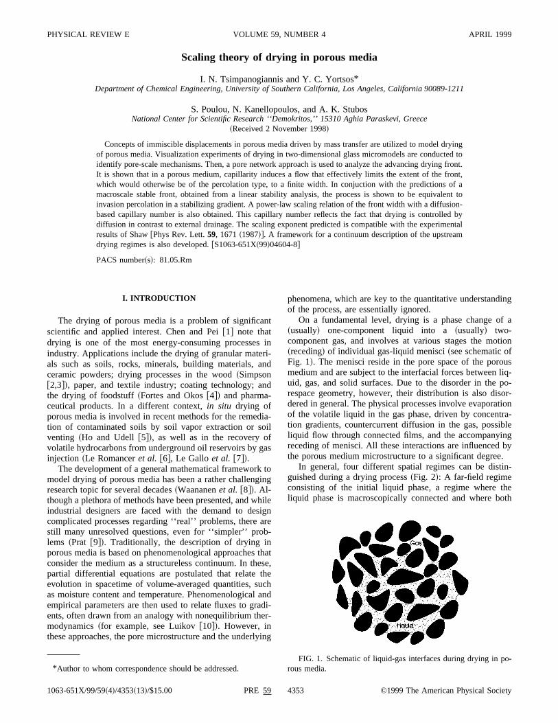
On a fundamental level, drying is a phase change o~usually! one-component liquid into a~usually! two-component gas, and involves at various stages the mo~receding! of individual gas-liquid menisci~see schematic oFig. 1!. The menisci reside in the pore space of the poromedium and are subject to the interfacial forces betweenuid, gas, and solid surfaces. Due to the disorder in therespace geometry, however, their distribution is also disdered in general. The physical processes involve evaporaof the volatile liquid in the gas phase, driven by concenttion gradients, countercurrent diffusion in the gas, possliquid flow through connected films, and the accompanyreceding of menisci. All these interactions are influencedthe porous medium microstructure to a significant degree
In general, four different spatial regimes can be distguished during a drying process~Fig. 2!: A far-field regimeconsisting of the initial liquid phase, a regime where tliquid phase is macroscopically connected and where b
FIG. 1. Schematic of liquid-gas interfaces during drying in prous media.
4353 ©1999 The American Physical Society

’’te
ir-toe
ivhanat
under
to
rocear
-r
lsoat
asrlie
a
fro
th
rize.leg
er., as
-n-
iveingalo-w.
ofthe
iefes,in
cha-heticalrgu-re-keyg isng
heaaof
ed.p-o-com-
ithheof
be
ead-lso
ry
eunt-
in
r-ase,or-tlyec-n a
eit
eic
4354 PRE 59I. N. TSIMPANOGIANNIS et al.
gas and liquid phases are ‘‘macroscopically continuous,third regime in which the liquid phase has been disconnecin individual clusters of variable sizes~blobs! as a result ofdrying, and a fourth regime consisting of the liquid phasethe form of pendular rings or films covering the solid suface, the thickness of which is progressively reduced,wards a ‘‘totally dry’’ regime. In the last three regimes thgas phase is macroscopically continuous. Shaw@11# has alsopostulated that liquid films may provide hydraulic connectity to the liquid phase in all three regimes. It is apparent tan appropriate account of the various pore-scale events ithese regimes is fundamental to the accurate representof any macroscopic description~Whitaker @12#!.
Pore-network approaches for describing drying of poromedia were recently proposed by Nowicki, Davis, aScriven@13# and in a series of papers by Prat and co-work~Prat @14,15#, Laurindo and Prat@16,17#!. In a related con-text, Pot et al. @18# used lattice-gas cellular automatasimulate evaporation phenomena in two-dimensional~2D!porous media. Nowicki, Davis, and Scriven@13# developed arather comprehensive pore-network simulation of the pcess, and accounted for both capillary and viscous forHowever, the authors did not delve into the particular pterns that develop or on their effect on the drying rates. P@14,15# and Laurindo and Prat@16,17# studied pattern formation during drying assuming capillary forces only and ignoing viscous forces. The importance of film flows was adiscussed@17#. Based on the assumption of percolation pterns and under isothermal conditions, they proceededcompute evaporation and drying rates by solving a qustatic diffusion equation in the gas phase. However, eadrying experiments in glass-bead packs by Shaw@11# sug-gested that viscous forces are not negligible, and in factneeded to explain the formation of a front width~separatingcontinuous liquid from gas! of a finite size. This, Shaw@11#attempted to scale using scaling expressions obtainedexternal drainage~see below!. Despite the limitation on vis-cous forces, however, Prat’s studies are important in
FIG. 2. Schematic description of drying regimes in porous mdia, obtained from 2D pore network simulations. Dots and whareas denote liquid-occupied regions, dark shaded areas denotoccupied regions.~Due the 2D topological limitations, a schematof the 2-phase bicontinuum regime is not feasible.!
ad
n
-
-tallion
s
s
-s.
t-at
-
-toi-r
re
m
at
they represent the first attempt to theoretically charactedrying patterns and their rate of change in porous media
As in other processes involving two-phase, immiscibflows in porous media, the following two aspects of dryinpatterns need to be understood:~i! Their geometrical struc-ture, which dictates transport and capacitance and~ii ! theirrates of change. This is the main motivation of this papWe consider the application of a pore-network approachin Nowicki, Davis, and Scriven@13#, Prat@14,15#, and Lau-rindo and Prat@16#, but with specific objectives to understand the structure of drying patterns, particularly in the frotal region. From such an analysis, the derivation of effectmacroscopic models can then be obtained. Drying, involvgas-liquid interfaces, can benefit from advances in the angous problem of external drainage, which is reviewed beloWhat is novel in drying, however, is the additional effectmass transfer in the gas phase, which actually drivesprocess. This needs to be analyzed in some detail.
The paper is organized as follows: First, we give a brreview of recent findings in isothermal drainage processwhich have a direct bearing on drying. Then, experiments2D micromodel geometries are presented to visualize menisms during drying and to help in the development of ttheory. Based on the experimental observations, a theoreapproach is subsequently developed, which combines aments borrowed from isothermal drainage and from thelated bubble growth problem, where mass transfer is aprocess. We use scaling arguments to show that dryinactually a process of invasion percolation in a stabilizigradient~IPSG! ~see below for a definition!, from which wecan infer the scaling of the front width as a function of tdrying parameters. To demonstrate the transition frompercolation-only pattern, which was studied by Prat, tostabilizing gradient and an IPSG, a linear stability analysisthe front in the appropriate geometries must be performThis analysis will precede the main theoretical develoments. We close by providing a framework for a macrscopic description based on transverse averages, and bymenting on the modeling of the other regimes.
We show that the scaling so obtained is compatible wShaw’s @11# experimental results. Thus, although near tleading edge of the front, the displacement pattern will bethe percolation type~assumed by Prat and co-workers tovalid for the entire pattern!, as the width of the front in-creases, viscous forces become increasingly important, ling to a displacement described by IPSG. Our analysis asheds light to a process of liquid flow, termed ‘‘capillapumping’’ by Le Romanceret al. @6#, in their modeling ofoil recovery from fractured reservoirs by gas injection. Wshow that this effect is actually the consequence of accoing for both capillary and viscous terms in the process. Asprevious pore-scale studies in drying~Nowicki, Davis, andScriven@13#, Prat@15#!, our analysis is restricted to isothemal problems. We also neglect convection in the gas phwhich is expected to be progressively of secondary imptance, and gravity. The effect of the latter can be direcincorporated. However, effects of heat transfer and convtion need a separate analysis, which will be attempted ifuture study.
-egas-

feaithn
f
detut
wrciat tt
tdenc
isce
acols
-n
oriror
fenitybe
izr
nt
ort
rco-is
de-ce-he
ta-
is-entryy
la-
erat-
teran-eilar
g
PRE 59 4355SCALING THEORY OF DRYING IN POROUS MEDIA
II. PRELIMINARIES
Drying involves gas-liquid interfaces and mass transand should be subject to an analysis similar to external drage and to bubble growth in porous media. Because ofexpected similarities, we briefly review in this section receadvances in these two areas.
Consider first, drainage, namely, the displacement owetting phase by a nonwetting phase in a porous mediumthe absence of phase change. In drainage, menisci resipores or at the entrance of pore throats with a curvacorresponding to the local capillary pressure, defined asdifference between the nonwetting~gas! and wetting~liquid!phase pressures,
Pc[Pnw2Pw52gH. ~1!
Here,g is the interfacial tension between the fluids,H is themean curvature of the meniscus and a zero contact angleassumed. In the absence of buoyancy and/or viscous fothe capillary pressure, thus the mean curvature, is spatuniform. A meniscus will penetrate a pore throat, adjacenwhich it resides, when the capillary pressure first exceedscapillary entry pressure for that pore throat~roughly equal to2g/r , wherer is the pore throat size!. In drainage at constanrate, the sequence of pore penetration can be modeleinvasion percolation~IP!, where at each time step only onpore throat is invaded, that with the least capillary resista~or, equivalently, the largest radius! among all throats at theperimeter of the interface. During this step, all other menremain stationary or fluctuate slightly. This type of displacment gives rise to a self-similar fractal pattern in the displing phase, which eventually approaches that of the perction cluster. The properties of the latter have been discusin detail in various publications@19,20#. Because of the selfsimilarity involved, however, defining a mean-front positiois not operationally useful.
However, if gravity and/or viscous forces are also imptant, a percolation pattern will not develop over the entregion of displacement. When only gravity forces are imptant, the capillary pressure will vary with the elevationh ofthe interface, sincePc5gxDrh, wheregx is the componentof gravity in the direction of displacement andDr5rw2rnw . Then, the displacement acquires the features odifferent pattern, namely, invasion percolation in a gradi~IPG! @21–26#. In this case, the competition between gravand capillary forces is expressed through the Bond num
B5gxDrk
g, ~2!
wherek is the permeability of the porous medium~which isroughly proportional to the square of a mean pore sk;r m
2 , Katz and Thompson,@27#!. Now, one needs to furthedistinguish two cases:
~i! If B.0, for example, in the downwards displacemeof a heavier by a lighter fluid, the two phases are separaby a front of finite widthsG , which scales with the Bondnumber as@21,22#
sG;B2n/~n11!, ~3!
rn-et
ainin
rehe
ases,llyohe
by
e
i--a-ed
-e-
at
r,
e
ted
wheren is the correlation length exponent of percolation. Fa nonzeroB, the front width is finite. Then, the front is noself-similar, but rather self-affine@28# @Fig. 3~a!#. Within thefront, the pattern has the fractal characteristics of the pelation cluster. However, upstream of the front, the patterncompact. Thus, a mean front position can be usefullyfined. In essence, this reflects the transition of the displament from an IP to a pistonlike pattern. The latter is tpattern that develops when only gravity~and not capillarity!acts~and which would be pistonlike in this case!. We shallrefer to this as IPSG. Hulinet al. @23# experimentally dem-onstrated the application of IPG in a drainage problem sbilized by gravity.
~ii ! On the other hand, ifB,0, for example, in the down-wards displacement of a lighter by a heavier fluid, the dplacement is invasion percolation in a destabilizing gradi~IPDG!. This pattern has the different features of capillafingering @Fig. 3~b!#, in which the displacement occurs binvading fingers of a mean width still given by Eq.~3!, thelocal characteristics of which are still controlled by percotion. This regime has been discussed in detail in Fretteet al.@29# and Meakinet al. @30#.
The effect of viscous forces is more complex. At largscales, where viscous effects predominate, two limiting pterns are expected, pistonlike displacement~PD! and viscousfingering, depending on whether the ratioM5mw /mnw , be-tween the viscosities of the two fluids, is smaller or greathan 1, respectively. Essentially, this reflects the SaffmTaylor instability @31#. At smaller scales, however, whercapillary forces are important, the problem becomes sim
FIG. 3. ~a! Self-affine front during external drainage indicatinan IPSG process.~From Xu, Yortsos, and Salin@33#.! ~b! Singlefinger in external drainage indicating an IPDG process.~From Cha-oucheet al. @26#.!

a-ner
upe
to
soaogbnd
g
,ionsifu
ain
Thns
ndts
uco
stoalisgby.lesd
uslasstes
net-in
of
stntssls
aoat00lassre-n-ct-fter
enu-
delap-wo
data
eri-
delthe
isatthe
dif-
orthethee in
4356 PRE 59I. N. TSIMPANOGIANNIS et al.
to IPSG~case of smallM! or IPDG ~case of largeM! ~Yort-sos, Xu, and Salin@32#, Xu, Yortsos, and Salin@33#!. In thefirst case, in particular, fully developed drainage involvesadvancing front of a finite widthsV , as in the case of stabilizing gravity, followed by a more compact pattern. The frowidth can be shown to scale with the front capillary numbCaF5vmnw /g, as@34,33#
sV;S CaF
S D 2n/@11z1n~D21!#
, ~4!
wherev is the front velocity,m denotes viscosity,S is thedimensionless variance of the pore-size distribution,z is theconductance exponent of percolation, andD is the fractaldimension of the percolation cluster. Values for the variopercolation exponents can be found in classical texts oncolation, for example, in Stauffer and Aharony@35#. Theproperties of these patterns and the conditions delineatingvarious regimes were recently discussed in detail in YortsXu, and Salin@32# and Xu, Yortsos, and Salin@33#.
Although subject to similar considerations, drying alinvolves the additional effect of mass transfer in the gphase, which actually drives the process. A certain analcan be drawn between drying and the problem of bubgrowth in porous media, recently investigated by Li aYortsos@36,37#, and Satik and Yortsos@38#, where the driv-ing force for phase change and the ensuing growth of thephase is diffusion of mass or heat in the liquid~for the caseof solution gas or boiling, respectively!. When a bubble~more properly a gas ‘‘cluster’’! grows in a porous mediumits pattern at small bubble sizes will be of the percolattype. However, at larger sizes, capillary forces are lessnificant, and the displacement pattern is controlled by difsion and viscous~and gravity! effects~Satik, Li, and Yortsos@39#!. Diffusion in the liquid is known to destabilize suchliquid-to-gas phase change, leading to a Mullins-Sekerkastability ~see@40,41# for the particular application!, thus thepattern gradually becomes of the viscous fingering type.boundaries in the parameter space that delineate patterbubble growth were described in Satik, Li, and Yortsos@39#by using scaling arguments and pore-network simulatioThe same authors also proposed kinetic expressions toscribe the rates of growth of bubble-growth patterns. Keytheir description was the modeling of the diffusion proceand its coupling with viscous and capillary phenomena. San approach could also be fruitfully used in the contextdrying.
It could be noted that because it is essentially a procesgas displacing liquid, one might naively anticipate dryinginvolve IPDG patterns of the viscous fingering type, in anogy with external drainage in which the displacing fluidless viscous, or with the bubble-growth problem at larsizes. However, this is misleading: drying is not drivenexternal injection, but byinternal diffusion in the gas phaseThis differs from external drainage, but also from bubbgrowth, where diffusion occurs in the liquid phase. Theprocesses conspire to give patterns that are characterizethe stabilizing IPSG process, as will be shown below.
n
t,
sr-
hes,
sy
le
as
g--
-
ein
s.e-
oshf
of
-
e
eby
III. EXPERIMENT
To visualize the mechanisms involved in drying in poromedia we conducted experiments in transparent etched-gmicromodels. These micromodels consist of two glass plafused together, on one of which a specific square porework pattern is etched. Micromodels have been valuableproviding an understanding of the qualitative featuresvarious displacement processes in porous media~see Buck-ley @42# for a review!. In the context of phase change, a morecent application involves the bubble-growth experimereported in Li and Yortsos@36# and the drying experimentby Laurindo and Prat@16#. In our application, the typicamicromodel has size 25 cm310 cm, while the etched poreare channels with an estimated depth of 100mm. The porebody/throat thickness is spatially distributed, followingspecified Rayleigh distribution, with an average pore thrradius of 450mm and an average pore body radius of 9mm. These dimensions are specified before etching the gplate. Due to imperfections in the glass and the lack of pcise control in etching and fusion, however, the final dimesions are somewhat different. Also, although originally reangular, the channels can become ‘‘eye-shaped’’ afusion, as pointed out by Chatzis, Morrow, and Lim@43# andVizica and Payatakes@44#. The final shape depends on thtime of fusion among other parameters. Details of the mafacturing procedure can be found in Chatzis@45#. One entryport and one exit port on opposite sides of the micromoserve to inject and recover the fluids. The experimentalparatus shown in Fig. 4 consists of the micromodel, of treservoirs for the supply of the liquid and gas phases~de-noted in the figure as ‘‘oil’’ and ‘‘gas’’! of a syringe pump,a camera for visualization, a video tape recorder, and aprocessing system. Typical liquids used weren-pentane,n-hexane, and distilled water. The gas phase in the expments was air.
The experiments consist of first saturating the micromowith the liquid phase and subsequently displacing it withgas at relatively high injection rates until the liquid phasemacroscopically disconnected from the two ports. At thtime the gas injection rate was decreased to low rates anddrying process commences. This arrangement is actuallyferent on the macroscopic scale than Shaw’s@11#, whereonly one side is open to flow, there is no primary drainageexternal liquid displacement, and the only mechanism formovement of menisci is due to mass transfer. However,basic drying mechanisms at the microscale are the sam
FIG. 4. Schematic of the experimental apparatus.

vein
caon
c
di
idcd
uithi
--
hee
mna,inililmethinvie
onering
lythehep ofmsis-
ingld
tedn-us
arr
n
in
in-ub-y tosfer.ore
ll-rity,
n
wer-willn
ust
ichat
nt,on-
nt
he
PRE 59 4357SCALING THEORY OF DRYING IN POROUS MEDIA
both experiments. In fact, the theoretical model to be deoped below will pertain to Shaw’s configuration. The madifference is in mass transfer, which in our experimentsalso occur by forced convection due to the particular cfiguration~see also Jia, Shing, and Yortsos@46# for a relatedapplication!. In most of the experiments, however, the injetion rate was kept quite low~of the order of 0.052 ml/min!resulting into small Peclet numbers and a predominantlyfusive mass transfer mechanism.
Figure 5 shows two snapshots of the interfacial patterndifferent times during drying. The evaporation of the liquand the resulting receding of the interface at various plaare apparent. We note the existence of many clusters offerent sizes, containing macroscopically disconnected liqThe clusters are disordered and reflect the difference incapillary characteristics of different pores. The interfacegenerally ‘‘rough,’’ although it is difficult to ascertain selfaffinity or self-similarity. Important findings from the visualization experiments included the following:
~i! Typically, the penetration of gas into the liquid and treceding of the meniscus occured in the form of suddjumps, one at a time, which were separated by finite tiintervals. These jumps known as ‘‘rheon’’ events in exterdrainage, reflect the fact that for a pore to be invadedcapillary pressure threshold must be exceeded, followwhich displacement and filling of the adjacent pore body woccur rapidly. During that time, interfaces pinned by caplarity in other pores are adjusted as a result of liquid incopressibility~see also below!. Rheon events will predominatwhen the displacement is controlled by capillarity, as wascase in many of these experiments. When, however, dryrates are fast, as was the case with the experiments involn-pentane, or at higher gas injection rates, the displacem
FIG. 5. Two different snapshots@~a! and ~b!# of the interfacialpatterns at two different times from the micromodel experime~system: air/n-hexane!. The linear dimensions are 6.5 cm3 3.5 cm.
l-
n-
-
f-
at
esif-d.e
s
nelagl--
eg
ngnt
was also found to occur at the same time in more thanpores, although several interfaces remained pinned duthe same time.
~ii ! Even though the plan views in Fig. 5 indicate gas-onoccupied regions, a careful monitoring of the changes inliquid-gas interface revealed that liquid films existed at tsurfaces of pores invaded by gas. Figure 6 is a close-uthe gas-liquid interface, and shows the trace of wetting filleft behind during the invasion of a pore by gas. The extence of films was also indirectly deduced from observthe emptying of some pores occupied by liquid, which woube topologically impossible in the absence of connecfilms. Wetting films in corners and crevices following draiage of a wetting liquid have been documented in variodrainage studies~e.g., see Lenormand, Zarcone, and S@47#!. In his experiments, Shaw@11# inferred that connectedliquid films help in the transport of liquid towards the opeedge of the cell where it can evaporate. Prat@14,15# andLaurindo and Prat@16,17# also reported the existence of thliquid films.
The above mechanisms of the drying process will becorporated in the pore-network theory to be developed ssequently. Before we proceed, however, it is necessarunderstand large-scale effects of diffusion and mass tranThese can be studied in the absence of capillarity and pmicrostructure.
IV. FRONT STABILITY IN THE ABSENCEOF CAPILLARITY
It was pointed out in a previous section that while smascale features of a displacement process are set by capillalarger-scale characteristics are set by transport~such as vis-cous flow or diffusion!. This is certainly the case both iexternal drainage~Xu, Yortsos, and Salin@33#! and in bubblegrowth ~Satik, Li, and Yortsos@39#!. The percolation patternwill ultimately ~at large capillary numbers, see also belo!evolve into a pattern dictated by the large scale. To undstand this pattern, and thus to infer whether the processbe of the IPSG or the IPDG type, the stability of drying in aeffective porous medium in the absence of capillarity mbe analyzed.
Consider a planar drying front advancing in an isotropand homogeneous effective medium, with a geometry tmimics the experiments by Shaw@11#, as shown in Fig. 7.The liquid phase consists of a vaporizing single componewhile the gas phase is a mixture of two components at c
s
FIG. 6. Close-up of the gas-liquid interface during drying in tmicromodel experiments. The linear dimensions are 1.0 cm3 0.5cm.

uosogidil
oniob
tafile
ositia-e
sd
reo
ngw
e
di-
the
n-a-
s
the
taken
ter-e
ce,
f aare
foeahst
4358 PRE 59I. N. TSIMPANOGIANNIS et al.
stant pressure. A sharp interface seperates gas from liqthus, for the purposes of this section, we ignore effectsmicrostructure or film flows. Isothermal conditions are asumed. The top boundary is open to gas flow, has zero mconcentration of the vaporized liquid, and has a constantpressure. The bottom boundary is impermeable to liquthus all changes in liquid content are due to drying. We wexamine the stability of the front to transverse perturbatiin the absence of capillarity. For the purposes of this sectwhich is to reveal macroscopic features, the analysis willbased on a continuum description. We consider quasisdiffusion in the gas phase and assume that the pro~which are generally time-dependent! are ‘‘frozen’’when theperturbation is imposed. Quasistatic diffusion is expectedbe valid when the ratio of the equilibrium concentrationthe volatile component in the gas phase to its molar denin the liquid phase is small, which is the case at low parpressures~see Appendix!. The more general problem involving unsteady-state diffusion and convection will be describin a separate study~see also Appendix!. Assuming a frozenstate during perturbations is a standard approach for thebility of time-varying base states~see, for example, Tan anHomsy @48#!.
Let the front that separates liquid- from gas-occupiedgions be denoted by the following equation in the notationFig. 7:
F~z,y,t ![z2F~y,t !50, ~5!
and recall the definitions
n5“F
u“Fu~6!
and
vn52Ft
u“Fu, ~7!
FIG. 7. A schematic of the planar drying front geometriesthe stability analysis of drying in an effective porous medium. Nthe indicated protuberance, concentration contours in the gas pare compressed leading to enhanced mass transfer, hence tolization of the protuberance.
id;f
-laras;lsn,etics
toftyl
d
ta-
-f
for the outer normal~pointing towards the liquid! and thenormal velocity at the front, respectively. The governiequations in the liquid-occupied region involve Darcy’s lafor the flow of the liquid phase,
ul52k
m l“Pl , ~8!
from which, and with the use of the continuity equation, wobtain a Laplace equation for the liquid pressure,
“
2Pl50. ~9!
This equation is subject to the following boundary contions:
Pl5Pv at z5F~y,t !, ~10!
wherePv is the gas pressure, assumed constant, due tosmall gas viscosity, and
]Pl
]z50 at z5L, ~11!
whereL denotes the longitudinal extent.For negligible convection and transient effects the co
densible componentA satisfies the quasistatic diffusion eqution ~see Appendix!,
“
2cA50, ~12!
wherecA is the concentration of the condensible species~seealso, Prat@14,15#!. The corresponding boundary conditionare
cA50 at z50 ~13!
and
cA5ce[xAec at z5F~y,t ! ~14!
at the inlet and the front, respectively. Here, we definedequilibrium mole fraction,xAe5PvA /Pv , wherePvA is thepartial pressure ofA, and the total gas concentrationc thatbecause of the assumed constant pressure, can also beas a constant~c5Pv /RT for an ideal gas, whereR is theideal gas constant andT is the absolute temperature!.
Concentration and pressure fields are coupled at the inface by mass balances. For the vaporizing liquid, we hav
2DAB
]cA
]n5
r l
MA~uln2vn! at z5F~y,t !, ~15!
whereDAB is the diffusion coefficient,r l is the mass densityof the liquid,MA is the molecular weight, andn denotes thenormal to the interface. The interface is a material surfathus,
vn5ugn . ~16!
The assumption made here is that the liquid consists osingle volatile component and that convection effectssecondary.
rraseabi-

rb
th
a
nc
t ttw
aa
wa
aat
her-s,
redtion
eenis-
in-y
nt ag of
bleeve,al-ap-
idi-
atthew-
eed,
hasedesudy.
ngreni-reichpor
e ra--owheratichthehe
PRE 59 4359SCALING THEORY OF DRYING IN POROUS MEDIA
Consider, now, the base state in the absence of pertutions ~denoted by superscript bar!. Then, the front is locatedat z5 f (t) and we readily find the base state.
c5zce
f ~ t !for 0,z, f ~ t !, ~17!
Pl5Pv for f ~ t !,z,L, ~18!
and
vn5 vz[ f 5cEMADAB
r l f. ~19!
The latter can be integrated to yield the front location@as-suming f (0)50#,
f 5A~2ceMADABt /r l !. ~20!
This expression also results in the quasistatic limit frommore general analysis presented in the Appendix.
For the stability analysis we assume a ‘‘frozen’’ statet5t0 , take normal modes, varying as exp@iay1v(t2t0)#,namely,
c5 c1es~z,t !exp~ iay1vt !, ~21!
Pl5Pv1eP~z,t !exp~ iay1vt !, ~22!
and
F~y,t !5 f ~ t !1e exp~ iay1vt !, ~23!
and inquire about the sign of the rate of growthv, of distur-bances of wave-numbera. In the above notation,e has di-mensions of length. Substituting Eq.~21! to Eq.~12! and theboundary condition~13! gives
s52A sinh~az!. ~24!
The constantA is evaluated by using boundary conditio~14! and the base state solution evaluated at the front lotion. After some calculations we arrive at the result,
s52cAesinh~az!
f sinh~a f !. ~25!
Working likewise with the pressure field we find thatP sat-isfies a Laplace equation, the solution of which is subjecthe no-flux and constant pressure conditions at theboundaries, respectively, is identically zero,P50. Thus, atthis level of approximation, the liquid phase is stagnant,intuitively expected. However, consideration of capillaritythe microscale~and the interfacial curvature it implies! leadsto viscous flow in the liquid phase, as will be shown beloThis flow will set the main features of the drying patternthe microscale.
A final substitution of the above into the coupling eqution at the front leads to the following expression for the rof growth of disturbances:
v52DABMAcxAea
r l f tanh~a f !,0. ~26!
a-
e
t
a-
oo
st
.t
-e
It is apparent that the rate of growthv is negative, whichimplies that this displacement is unconditionally stable. Tphysical intrepretation of the stability result is straightfoward: If a protuberance of the front into the gas region formgas-phase diffusion rates will be higher at the tip compato the base, due to the compression of isoconcentracurves at the tip~Fig. 7!. In the absence of liquid flow, thiswill result in a locally larger velocity at the tip, hence in thsmoothing of the protuberance, and in stability. Thus, evthough it is effectively a process of a less viscous fluid dplacing a more viscous fluid in a porous medium~where inexternal drainage one would expect a viscous fingeringstability!, the fact that the process is driven internally bdiffusion in the gas phase renders the frontal displacemestable process. In a sense, this is analogous to the meltina solid, in which the receding interface is also linearly sta~Langer@40#!. On the other hand, this is in contrast with thproblem of bubble growth in porous media referred to abowhere the process is also internally driven by diffusion,though in the liquid phase, and where in the absence of cillarity, the problem is linearly unstable~Li and Yortsos@41#!. The phase change analogy with that problem is solfication in a supersaturated solution.
The important implication of the previous analysis is thin the absence of capillary forces the drying pattern inporous medium will be PD. Because of the relatively lodrying rates in applications, however, capillarity will be important over sufficiently small scales~compare with Fig. 5!and must be considered, as shown below. Before we procwe note that a qualitatively similar result to Eq.~26! is alsoexpected in the more general problem, where net gas pconvection is considered. This analysis, which also incluspherical geometries, will be considered in a separate st
V. FRONT DESCRIPTION USING A PORE-NETWORKANALYSIS
Consider now a description of the frontal region duridrying by accounting for the effect of the pore structu~Figs. 5 and 6!. Locally, the interface is described by aequation similar to Eq.~5!, across which boundary condtions ~15! and~16! apply. However, here menisci in the pospace must conform to the curvature of the pore in whthey reside. Thus, across the meniscus, liquid and vapressures are related through the capillary pressure
Pl5Pv22g
r, ~27!
where, assuming locally spherical shapes, the mean pordius of curvature isr. A convection-diffusion equation describes mass transfer in the vapor phase, while the fluid flin both phases is described locally by Stoke’s law. In tfollowing, we will focus on the structure of the front. Fothis, capillarity must be considered. We will show first ththe latter induces a viscous flow, the magnitude of whdictates the extent of the front and its pattern. Then,scaling of the front width and the basic properties of tpattern are discussed.
re
e;
asin
idil
re
ieolk
tiomced
Erdth
a-g
ws
ob-reof
a
g
re in
beere
as-e
ca-hech,a
the
nt
tedallve,are
r isallyn of
s-
diesa
heaous
of
4360 PRE 59I. N. TSIMPANOGIANNIS et al.
A. Capillarity-induced flow „capillary pumping …
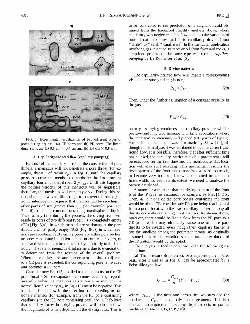
Because of the capillary forces in the constriction of pothroats, a meniscus will not penetrate a pore throat, forample, throati of radius r p,i in Fig. 6, until the capillarypressure across the meniscus exceeds for the first timecapillary barrier of that throat, 2g/r p,i . Until this happens,the normal velocity of this meniscus will be negligibltherefore, the meniscus will remainpinned. During this pe-riod of time, however, diffusion proceeds over the entire gliquid interface that requires that menisci will be recedingother pores of size greater thanr p,i ~for example, porej inFig. 6! or along corners containing nondisplaced liquThus, at any time during the process, the drying front wreside in pores of two different types:~i! completely empty~CE! @Fig. 8~a!#, in which menisci are stationary at the pothroats and~ii ! partly empty~PE! @Fig. 8~b!# in which me-nisci are receding. Partly empty pores are either pore bodor pores containing liquid left behind in corners, crevices,films and which might be connected hydraulically to the buliquid. The rate of meniscus displacement due to evaporais determined from the solution of the overall probleWhen the capillary pressure barrier across a throat adjato a CE pore is exceeded, the corresponding pore is invaand becomes a PE pore.
Consider now Eq.~15! applied to the meniscus on the Cpore throati. Since evaporation continues occurring, regaless of whether the meniscus is stationary or moving,normal liquid velocityuln in Eq. ~15! must be negative. Thisimplies a liquid flow in the direction from receding to sttionary menisci~for example, from the PE pore containincapillary j to the CE pore containing capillaryi!. It followsthat capillary forces in a drying process will induce a flothe magnitude of which depends on the drying rates. Thi
FIG. 8. Experimental visualization of two different typespores during drying: ~a! CE pores and~b! PE pores. The lineardimensions are~a! 0.6 cm3 0.4 cm and~b! 1.4 cm3 0.8 cm.
ex-
the
-
.l
s,r
n.nted
-e
,is
to be contrasted to the prediction of a stagnant liquidtained from the linearized stability analysis above, whecapillarity was neglected. This flow is due to the variationpore throat curvatures and it is capillarity driven~from‘‘large’’ to ‘‘small’’ capillaries !. In the particular applicationinvolving gas injection to recover oil from fractured rocks,simplified process of the same type was termedcapillarypumpingby Le Romanceret al. @6#.
B. Drying patterns
The capillarity-induced flow will impart a correspondinviscous pressure gradient; hence,
Pl , j.Pl ,i . ~28!
Then, under the further assumption of a constant pressuthe gas,
Pc,i.Pc, j , ~29!
namely, as drying continues, the capillary pressure willpositive and may also increase with time in locations whthe meniscus is stationary and pinned~CE pores of typei!.An analogous statement was also made by Shaw@11#, al-though in his analysis it was attributed to countercurrent gliquid flow. It is possible, therefore, that after sufficient timhas elapsed, the capillary barrier at such a pore throati willbe exceeded for the first time and the meniscus at that lotion will also start receding. This mechanism restricts tdevelopment of the front that cannot be extended too muor become very tortuous, but will be limited instead tofinite width. To estimate its extent, we need to analyzepattern developed.
Assume for a moment that the drying pattern of the frois of the IP type, as assumed, for example, by Prat@14,15#.Then, all but one of the pore bodies containing the fronwould be of the CE type, the only PE pore being that invadfrom a pore throat with the least capillary barrier, amongthroats currently containing front menisci. As shown abohowever, there would be liquid flow from the PE pore toCE pore, which may ultimately cause one or more pothroats to be invaded, even though their capillary barrienot the smallest among the perimeter throats, as originassumed. Under such conditions, therefore, the evolutiothe IP pattern would be disrupted.
The analysis is facilitated if we make the following asumptions:
~a! The pressure drop across two adjacent pore bo~e.g., sitesk and m in Fig. 6! can be approximated byPoiseuille-type law,
Qk→m5Gkm
m l~Pl ,k2Pl ,m!, ~30!
where Qk→m is the flow rate across the two sites and tconductanceGkm depends only on the geometry. This isstandard assumption in modeling displacements in pormedia~e.g., see@13,36,37,49,50#!.
rmhaa
ffung
theinat
inithetilis
b
b
thtio
sh
relytire
bee
-
ha
e-ires
redto
era
fla-
ityf
is-es
e
er
sble
d
-the
theesn
posi-
areller
PRE 59 4361SCALING THEORY OF DRYING IN POROUS MEDIA
~b! The pressure in the gas phase is spatially unifoGiven the small value of the gas viscosity compared to tof the liquid, this assumption is expected to be valid evenrelatively large drying rates.
~c! The transport in the gas phase is by quasistatic dision only. Under certain conditions that favor large dryirates~for example, elevated temperatures!, convection in thegas phase can be important. To infer its effect, however,momentum balance in the gas phase needs to be considAn extensive account of the more general problem uspore-network simulation will be considered in a separstudy.
As inferred from the linearized stability analysis above,the absence of capillarity, the front would be pistonlike, wsome local roughness. Capillarity will keep interfaces, othwise favored to grow by diffusion, pinned in place, untheir capillary pressure barrier is exceeded. The characterlength over which percolation rules apply and the patternof the IP type is estimated below.
Consider drying in a pore network of lateral extentL. Wewill denote the dimensionless mean position of the frontXf(t) and its width bys f t(t), or by s f(t), where after suf-ficiently large times f t(t) @or s f(t)# !Xf(t). Here, lengthshave been dimensionalized using the pore lengthl, subscriptft indicates front tail in 3D and subscriptf indicates front in2D geometries~e.g., see Gouyet, Rosso, and Sapoval@24#,for the difference in the two geometries!. Contrary to thecase of a 2D square lattice, to be discussed below, herephases can be continuous simultaneously.
If we were to neglect any viscous pressure drop inliquid phase, the capillary pressure, hence the percolaprobability p, on the front would be spatially constant~thepercolation probability being equal to the percolation threold p5pc , where, for 3D cubic lattices,pc50.25 and for 2Dsquare lattices,pc50.5!. Due to the capillary pumpingmechanism described earlier, however, the capillary psure, hence the percolation probability, will vary spatialFor a constant gas pressure, the characteristic variauDPcu across the front is related to that of the liquid pressunamely,
uDPcu5uDPl u. ~31!
Because the flow of the liquid in a pore network candescribed by Poiseuille’s law, and the displaced phascontinuous, then,
uDPl u;uDm ls f tl
k, ~32!
where we introduced the characteristic velocityuD and thepermeabilityk ~which scales approximately asl 2!. The char-acteristic velocityuD is due to diffusion, and to a first approximation,
uD;DABMAc
r lU]xA
]n U;DABMAcxAe
r l lX f, ~33!
where we estimated concentration gradients in the gas pby their base-state values. Substitution into Eq.~31! gives thefollowing result for the variation ofPc in the front region;
.tt
-
ered.ge
r-
ticis
y
oth
en
-
s-.on,
is
se
uDPcu;DABMAcxAem l
r l l2
s f t
Xf. ~34!
Equations~32!–~34! are order-of-magnitude estimates. Dtermining the exact pressure and concentration fields requthe solution of flow and transport problems in a disordepore network, which are coupled at the front accordingEq. ~15!, with vn50 for all CE pores and withun5S fun /Nf , for the single PE pore, where the sum is ovall Nf CE pores at the front. The development of suchsimulator is currently in progress@51#. Nonetheless, order omagnitude estimates are useful for obtaining scaling retions.
Consider now the variation of the percolation probabilin the front region, which will be affected by the variation oPc . The two are related as follows:
uDPcu;2gS
r muDpu, ~35!
whereS is the dimensionless variance of the pore size dtribution a(r ), and r m is a characteristic pore size. In thderivation of Eq. ~35! we made use of the resultPc52g/r and p5* r
`a(r )dr. Use of Eq.~35! in Eq. ~34!and substitutingr m; l gives the following expression for thvariation ofp:
uDpu;CaD
2S
s f t
Xf, ~36!
where we introduced a diffusion-based capillary numbCaD5DABMAm lcxAe /g lr l . This capillary number includesthe supersaturationCe5cxAe , which drives the drying pro-cess, leading to the characteristic velocityDAB / l;DAB /Ak. A similar diffusion-based capillary number waused in the related phase change problem involving bubgrowth by Li and Yortsos@36,37#, and Satik, Li, and Yortsos@39#. This reflects the fact that drying is internally driven andifferentiates the process from external injection.
The final step for determinings f t makes use of a selfconsistency argument, similar to IPG. As the process infrontal region is in the percolation regime, thenp must fol-low the percolation scaling@24#,
up2pcu;s f t2~1/n! . ~37!
Substitution of Eq.~37! in Eq. ~36! gives the final scalingresult,
s f t;S 2SXf
CaDD n/~11n!
, ~38!
This equation sets the length scale at the front over whichIP pattern is valid. By definition, this length scale coincidwith the front-tail width. The scaling is identical to that iIPSG, provided that the Bond number is identified asB5CaD/2SXf . According to Eq.~38!, the front width in-creases as the capillary number decreases, as the fronttion increases~namely, as the drying rates slow down!, or asthe disorder in the medium increases. Thus, wider frontsexpected for higher values in the interfacial tension, sma

hen
ithhe
user
he
ned
ath
thleod
vai
ri-
llyt
derew
et-p
itethdtpaise
hew
llteal
thevely
sednce
atel-e isrre-ting
ad-d
awe
ntalris-
ow-s of
is-inhetheoweas-As-o-weheXu,
-t of
4362 PRE 59I. N. TSIMPANOGIANNIS et al.
liquid viscosities, and larger drying times. Given that tvelocity of the frontv f is inversely proportional to its meaposition ~recall the base-state scalingXf;At!, we furtherrewrite Eq.~38! as
s f t;S 2S
v fCaDD n/~11n!
. ~39!
This expression will be used below for a comparison wthe experimental data. Finally, it is worth noting that texponent found is identical to Lenormand’s@49# for the de-lineation of the percolation limit in the drainage of a viscofluid, even though the two problems are actually quite diffent.
We summarize this section as follows: During drying tfrontal region consists of a front of a finite widths f t . Withinthe front, the displacement has the fractal properties of ainterface. Upstream of the front, however, the displacemis compact. Therefore, the process can be approximateIPSG. Xu, Yortsos, and Salin@33# show how various prop-erties of the front during displacement processes can beproximated by simple versions of IPSG. The scaling ofwidth of the front is given by Eq.~38!; thus, the front widthis predicted to increase with increasing distance fromboundary. As in other problems, where growth is controlinternally, namely, by diffusion within one of the twphases, the appropriate capillary number is based on thefusive strength and the supersaturation applied. Typicalues obtained fall within the range of external drainageporous media.
VI. COMPARISON WITH EXPERIMENTS
To check the validity of the theory we used the expemental results of Shaw@11#. These experiments were conducted in a Hele-Shaw cell of thickness 15–20mm, packedwith glass beads of size 0.5mm. We estimate that the ceconsisted of 30–40 bead layers, thus pertaining effectivela 3D geometry. The experimental configuration is similarthat studied theoretically above, with one side of the moopen to purge the drying liquid, while all other sides weimpermeable to flow. For these experimental conditionsestimated thatCaD is of the order of 1028. Figure 9 re-printed from Shaw@11# shows in logarithmic coordinates thscaling of the front width with the front velocity. The leassquares fit to the data gives a straight line with slo20.4860.1. Compared to the theoretical equation~39!,which also predicts a straight line with slope20.47 for 3Dand 20.57 for 2D, the agreement is, at first glance, qugood. However, a more careful comparison shows thatcannot be considered conclusive. Given that the front wiin Shaw’s experiments is several times larger than the sing of the cell, it is likely that the pattern developmentquenched along the third dimension, and that the experimis effectively in a 2D geometry. Under such conditions, tagreement is not as strong. Furthermore, the 3D scalingdeveloped for the front tail widths f t , where the pattern isfractal, which may not be the same quantity experimentameasured. Thus, even under the assumption of a 3D pattheoretical predictions and experimental results may actupertain to two different quantities~different definitions of
-
IPntas
p-e
ed
if-l-
n
-
tool
e
e
ishc-
nt
as
yrn,ly
front width!. For these reasons, although compatible withexperiments, the theory presented cannot be conclusiconfirmed from these experiments.
Shaw @11# used Wilkinson’s @34# theory for externaldrainage to interpret the experimental results. As discusin a previous section, this power law has the dependeshown in Eq.~4! with an exponent that equals20.38 or20.25 in 2D or 3D, respectively. We believe, however, ththe immiscible, external drainage theory is actually not revant to the present problem that as explained abovdriven by diffusion in the gas phase, and where the cosponding viscous pressure drop is in the displaced wetphase. By contrast, scaling Eq.~4! reflects the stabilizingeffect of viscous forces occurring in thedisplacing phase~which here is the relatively nonviscous gas phase, thus leing to an apparent contradiction! ~see also Xu, Yortsos, anSalin @33#!. The inadequacy of Eq.~4! was recognized byShaw@11# who subsequently proposed a different power lsimilar to Eq. ~39!, without, however, elaborating on thmass transfer aspects of the problem.
VII. IMPLICATIONS FOR A MACROSCOPICDESCRIPTION
The previous section described the structure of the froregion that because of its percolation and fractal charactetics requires a local analysis. In the upstream regimes, hever, a macroscopic description is possible. The elementthis description are discussed below.
Consider first the pattern upstream of the front. The dcussion will be restricted to 3D geometries, where flowthis regime is bicontinuous. Immediately adjacent to tfront, there exists a bicontinuous region upstream ofleading edge, where the pattern is locally IP, except that nthe process is above the percolation threshold, as an incring number of smaller-size throats have been invaded.suming a sufficiently small slope in the liquid saturation prfile, volume-averaged quantities can be defined; hence,can postulate a continuous description in this region. Tanalogous problem for drainage processes was studied in
FIG. 9. Variation of the width of the drying front with its average velocity. A least-squares fit to the data gives an exponen20.4860.1. ~From Shaw@11#.!
s
l-
tio
an,sth
idow
insnn
ateexn
f
sth
e
o
oncacn
nem
ese
ce-delex-n-as-orker-ed
emvec-
dif-ro-edgnt,iteleultof
ashatle-heith
fel-led
edheby
tc-of
doff
oreand
PRE 59 4363SCALING THEORY OF DRYING IN POROUS MEDIA
Yortsos, and Salin@33#. Using transverse averages, the mabalance on the liquid reads as
r lFf ]Sl
]t1
]ql ,z
]z G52R, ~40!
where the liquid flow rateql ,z is expressed using a generaized Darcy’s law,
ql ,z52kkr ,l~Sl !
m l
]Pl
]z, ~41!
involving the relative permeability functionkr ,l(Sl). The liq-uid pressure is related to the capillary pressure funcPc(Sl) via
Pl5Pv2Pc~Sl !. ~42!
The two functionskr ,l(Sl) andPc(Sl) correspond to primarydrainage, and they can be computed in a straightforwfashion using IP. The rate of evaporatioR[(DABMAc/V)*Alg
(]xA /]n)dA, expresses the net mastransfer from the liquid to the gas phase, occurring overgas-liquid interfacial areaAlg , whereV is volume andn isthe unit normal to the interface pointing towards the liquIn the dilute-limit approximation considered here, this prcess is linear with respect to the concentrations; thus,may further take
R5DABMAc
l 2 ~xAe2xAg!G~Sl !, ~43!
wherexAg is the transverse average of the mole fractionthe gas phase. Because the pattern of all interfaces isdictated by IP~although here it is above the percolatiothreshold!, the effective gas-liquid area and the dimensioless scaling functionG(Sl) can be computed by solvingquasistatic diffusion problem around a percolation clusThe results of this study will be reported elsewhere. Wepect, however, thatG has a nonmonotonic dependence, vaishing both near the front~whereSl→1! and far upstream othe front ~whereSl approaches zero!.
The system of Eqs.~40!–~43! is completed with a masbalance for the volatile component in the gas phase. Indilute limit, the overall mass balance reads
f]Sg
]t1
]qg,z
]z50, ~44!
while the mass balance for the volatile component becom
fSg
]xAg
]t1qg,z
]xAg
]z5
]
]z SD~Sl !]xAg
]z D1Rc
, ~45!
where the diffusion coefficientD(Sl) is to be computed froma percolation study. The system of Eqs.~40!–~45! can besolved to determine the saturation profiles in the regimebicontinuous phases.
The regime far upstream of the front consists of discnected ganglia of the liquid phase. Reasoning as in the sing analysis for the front, we can conclude that their charteristic size has the same scaling as given for the fro
s
n
rd
e
.-e
till
-
r.--
e
s
f
-al--t,
namely, Eq.~38!, where nowXf denotes the average locatioof these stationary ganglia. The description of this problcan still be obtained with the above equations~40!–~45!,except that the liquid velocity must now be set to zero. Thproblems are currently under study.
VIII. CONCLUSIONS
In this paper we used concepts of immiscible displaments in porous media driven by mass transfer to mocertain aspects of drying of porous media. Visualizationperiments of drying in 2D glass micromodels were coducted to identify mechanisms concerning the motion of gliquid interfaces at the pore scale. Then, a pore netwapproach was introduced, utilizing arguments from isothmal drainage, particularly IPSG, and from the relatbubble-growth problem.
A specific objective of this work was the analysis of thfrontal region separating the initial liquid from the upstreatwo-phase region. A linear stability analysis in an effectiporous medium, in the absence of capillarity or microstruture, showed that planar drying fronts are stable due tofusion in the gas phase. For a porous medium with a micstructure, however, capillarity induces a viscous flow, termin other contexts as ‘‘capillary pumping.’’ The developinpressure gradients effectively limit the extent of the frowhich would otherwise be of the percolation type, to a finwidth. In conjunction with the prediction of a macroscastable front, capillarity, diffusion, and viscous effects resin a process similar to IPSG. A power-law scaling relationthe front width with a diffusion-based capillary number wthen developed. This capillary number reflects the fact tthe process is internally driven due to diffusion, as in bubbgrowth problems but in contrast to external drainage. Tscaling exponent predicted was found to be consistent wthe experiments of Shaw@11#, although a conclusive proowas not obtained. A continuum description was also devoped for the regimes upstream of the front; the detaianalysis of which will be reported in a separate study.
ACKNOWLEDGMENTS
The research of I.N.T. and Y.C.Y. was partially supportby U.S. DOE Contract No. DE-FG22-96BC1994/SUB. Tresearch of S.P., A.K.S., and N.K. was partially fundedthe JOULE Programme of the European Commission~Con-tract No. JOF3-CT95-0008!. All of these sources of supporare gratefully acknowledged. We would also like to aknowledge the help of N. Konstantinou and G. PetrouNCRS ‘‘Demokritos’’ in the micromodel tests. I.N.T. woulalso like to acknowledge the hospitality of the InstitutePhysical Chemistry of NCRS ‘‘Demokritos’’ where part othe experimental work was conducted.
APPENDIX
In this appendix we consider the base state for the mgeneral problem that includes unsteady-state diffusionconvection. The condensible componentA satisfies the massbalance
as
-
oc
th
gacan
er
ctib
t
rb
r
e,
ot-
le
di-
lrd,
the
4364 PRE 59I. N. TSIMPANOGIANNIS et al.
]cA
]t1“•NA50, ~A1!
whereNA is its molar flux, expressed for a binary mixture
NA52cDAB“xA1xA~NA1NB!. ~A2!
Here,cA is the molar concentration,xA is the molar fractionof A (cA5cxA), andNB is the molar flux of the noncondensible species. The latter is also conserved,
]cB
]t1“•NB50. ~A3!
The corresponding boundary conditions read
xA50 at z50 ~A4!
and
xA[xAe5PvA~T!
Pvat z5F~y,t ! ~A5!
at the inlet and the front, respectively. The equilibrium vappressurePvA is a function of temperature, among other fators.
For a porous medium, the mass-averaged velocity ingas phase,uv5(MANA1MBNB) /(rA1rB) , satisfies Dar-cy’s law
uv52k
mv“Pv , ~A6!
whereM denotes molecular weight. Because of the smallviscosity, however, the gas pressure can be assumedstant, which for isothermal conditions also implies a constmolar concentrationc. Note also, that from Eq.~A6! and thedefinition of the mass-averaged velocity, we have the genrelation
“3uv50. ~A7!
This can be used in the more general case where 2D contration and pressure fields must be evaluated. Concentraand pressure fields are coupled at the interface by massances. For the vaporizing liquid,
j An[MANAn2rAevn5r l~uln2vn! at z5F~y,t !,~A8!
while for the noncondensible componentB,
j Bn[MBNBn2rBevn50 at z5F~y,t !, ~A9!
where j is the mass flux,vn is the velocity of the recedinginterface,r l is the mass density of the liquid, andrAe andrBe denote mass density of speciesA or B in the gas phase aequilibrium; thusrAe5xAecMA .
Consider now the base state in the absence of pertutions ~denoted by superscript bar!. Then, all fluxes are alongthe z direction only, the front is located atz5 f (t) and thebase state is described as follows. The base-state liquid psure corresponds to a stagnant liquid,
r-
e
son-t
al
en-onal-
a-
es-
Pl5Pv for f ~ t !,z,L. ~A10!
The base-state fluxes are
NAz'2r l
MAvz and NBz5
rBe
MBvz , ~A11!
where we impliedrAe!r l , while the mole fraction is givenfrom
NAz52cDAB
dxA
dz1 xA~NAz1NBz!. ~A12!
To solve the unsteady-state problem we take theansatzthatthe front position is proportional to the square root of tim
f ~ t !52lADABt, ~A13!
wherel is a dimensionless parameter to be determined. Ning that for constantc, the total molar flux is constant,
NAz1NBz5r l f F rBe
r lMB2
1
MAG , ~A14!
the mass balance for speciesA, Eq. ~A1! reads
c]xA
]t1r l f F rBe
r lMB2
1
MAG ]xA
]z5cDAB
]2xA
]z2 , ~A15!
where we made use of Eq.~A11!, dot denotes derivative withrespect to time and we evaluatedvz at z5 f (t). We will seekthe solution of this problem using the similarity variabh5z/2ADABt. Then, Eq.~A15! becomes
x912x8~h2f!50, ~A16!
where primes denote derivative with respect toh and wedefined
f5lr l
c F rBe
r lMB2
1
MAG . ~A17!
This equation is to be solved subject to the boundary contions
xA5xAe at h5l ~A18!
and
xA50 at h50. ~A19!
Note that because the integration interval here is 0,z, f (t) and f (0)50, there is no need to satisfy an initiacondition, in contrast to the problems considered by BiStewart, and Lightfoot@52# and Cussler@53#. The latter au-thors solved a similar problem, except that they madeassumptions of a fixed interface@52# or of a vanishing fluxfor speciesB @53#.
The solution of Eqs.~A16!–~A19! is
xA5xAe
erf~h2f!1erff
erf~l2f!1erff. ~A20!

s
uc
a
h
veaticofile
PRE 59 4365SCALING THEORY OF DRYING IN POROUS MEDIA
The unknown parameterl is obtained by substitution of thisolution in the first equation of~A11!. After some manipu-lations, we find thatl solves the transcendental equation,
l~12xAe!5cxAeMA exp@2~l2f!2#
Apr l@erf~l2f!1erff#. ~A21!
In Eq. ~A21!, it must be recalled thatf is proportional tol@see Eq.~A17!#, and we assumed that the gas density is msmaller than the liquid density. Equation~A21! shows thatthe front grows proportionally to the square root of time,expected. Of interest is the dilute limituxAe@(MA /MB)3(rBe /r l)21#u!1, considered in the main text, in whiccasel!1 and Eq.~A21! gives
de
G.
g
s
-
ki
M
y
C
h
s
l25xAecMA
2r l, ~A22!
which when inserted in Eq.~A13! gives
f 5A~2cDABMAxAe /r l !t, ~A23!
which is the equation in the text. In this limit, the convectiterm vanishes and the concentration field is quasist~namely, it satisfies a Laplace equation, the base-state prfor the mole fraction being linear!.
Lett.
v. A
. A
v-
yn.
rt
s
@1# P. Chen and D. C. T. Pei, Int. J. Heat Mass Transf.32, 297~1989!.
@2# W. T. Simpson, Drying Technology2, 235 ~1983!.@3# W. T. Simpson, Drying Technology3, 353 ~1984!.@4# M. Fortes and M. R. Okos,Advances in Drying~Hemisphere
Publishing, New York, 1980!, Vol. 1, pp. 119–154.@5# C. K. Ho and K. S. Udell, Int. J. Heat Mass Transf.38, 339
~1995!.@6# J. F. Le Romancer, D. Defives, F. Kalaydjian, and G. Ferna
~unpublished!.@7# Y. Le Gallo, J. F. Le Romancer, B. Bourbiaux, and
Fernandes, Report No. SPE 38924~unpublished!.@8# K. M. Waananen, J. B. Litchfield, and M. R. Okos, Dryin
Technology11, 1 ~1993!.@9# M. Prat, Drying Technology9, 1181~1991!.
@10# A. V. Luikov, Heat and Mass Transfer in Capillary PorouBodies~Pergamon, London, 1966!.
@11# T. M. Shaw, Phys. Rev. Lett.59, 1671~1987!.@12# S. Whitaker, Adv. Heat Transfer13, 119 ~1977!.@13# S. C. Nowicki, H. T. Davis, and L. E. Scriven, Drying Tech
nology 10, 925 ~1992!.@14# M. Prat, Int. J. Multiphase Flow19, 691 ~1993!.@15# M. Prat, Int. J. Multiphase Flow21, 875 ~1995!.@16# J. M. Laurindo and M. Prat, Chem. Eng. Sci.51, 5171~1996!.@17# J. M. Laurindo and M. Prat, Chem. Eng. Sci.53, 2257~1998!.@18# V. Pot, C. Appert, A. Melayah, D. H. Rothman, and S. Zales
J. Phys. II6, 1517~1996!.@19# D. Wilkinson and J. F. Willemsen, J. Phys. A16, 3365~1983!.@20# J. Feder,Fractals ~Plenum, New York, 1988!.@21# D. Wilkinson, Phys. Rev. A30, 520 ~1984!.@22# B. Sapoval, M. Rosso, and J. F. Gouyet, J. Phys.~France! Lett.
46, L149 ~1985!.@23# J. P. Hulin, E. Clement, C. Baudet, J. F. Gouyet, and
Rosso, Phys. Rev. Lett.61, 333 ~1988!.@24# J. F. Gouyet, M. Rosso, and B. Sapoval, Phys. Rev. B37, 1832
~1988!.@25# A. Birovljev, L. Furuberg, J. Feder, T. Jossang, K. J. Malo
and A. Aharony, Phys. Rev. Lett.67, 584 ~1991!.@26# M. Chaouche, N. Rakotomalala, D. Salin, B. Xu, and Y.
Yortsos, Phys. Rev. E49, 4133~1994!.@27# A. J. Katz and A. H. Thompson, Phys. Rev. B34, 8179~1986!.@28# A. L. Barabasi and H. F. Stanley,Fractal Concepts in Surface
s
,
.
,
.
Growth ~Cambridge University Press, Cambridge, 1995!.@29# V. Frette, J. Feder, T. Jossang, and P. Meakin, Phys. Rev.
68, 3164~1992!.@30# P. Meakin, J. Feder, V. Frette, and T. Jossang, Phys. Re
46, 3357~1992!.@31# P. G. Saffman and G. I. Taylor, Proc. R. Soc. London, Ser
245, 312 ~1958!.@32# Y. C. Yortsos, B. Xu, and D. Salin, Phys. Rev. Lett.79, 4581
~1997!.@33# B. Xu, Y. C. Yortsos, and D. Salin, Phys. Rev. E57, 739
~1998!.@34# D. Wilkinson, Phys. Rev. A34, 1380~1986!.@35# D. Stauffer and A. Aharony,Introduction to Percolation
Theory~Taylor & Francis, London, 1992!.@36# X. Li and Y. C. Yortsos, AIChE. J.41, 214 ~1995!.@37# X. Li and Y. C. Yortsos, Chem. Eng. Sci.50, 1247~1995!.@38# C. Satik and Y. C. Yortsos, J. Heat Transfer118, 455 ~1996!.@39# C. Satik, X. Li, and Y. C. Yortsos, Phys. Rev. E51, 3286
~1995!.@40# J. S. Langer, Rev. Mod. Phys.52, 1 ~1980!.@41# X. Li and Y. C. Yortsos, Phys. Fluids6, 1663~1994!.@42# J. S. Buckley, inInterfacial Phenomena in Petroleum Reco
ery, edited by N. R. Morrow~Dekker, New York, 1990!.@43# I. Chatzis, N. R. Morrow, and H. T. Lim, SPE J.23, 311
~1983!.@44# O. Vizica and A. Payatakes, PCH PhysicoChem. Hydrod
11, 187 ~1989!.@45# I. Chatzis, New Mexico Institute of Technology, PRRC Repo
No 80-12, 1982~unpublished!.@46# C. Jia, K. Shing and Y. C. Yortsos, J. Contam Hydrol.35, 363
~1999!.@47# R. Lenormand, C. Zarcone, and A. Sarr, J. Fluid Mech.135,
337 ~1983!.@48# C. T. Tan and G. M. Homsy, Phys. Fluids29, 3549~1986!.@49# R. Lenormand, Proc. R. Soc. London, Ser. A423, 159 ~1989!.@50# M. Blunt and P. King, Transp. Porous Media6, 407 ~1991!.@51# S. Poulou, A. K. Stubos, and Y. C. Yortsos~unpublished!.@52# R. B. Bird, W. E. Stewart, and E. L. Lightfoot,Transport
Phenomena~Wiley, New York, 1960!.@53# E. L. Cussler,Diffusion: Mass Transfer in Fluid System
~Cambridge University Press, Cambridge, 1984!.


