RA TURNOUT WORKSHOP
National Turnout Workshop Page 1 of 47 Perth – Nov, 2010
National Turnout Workshop – Newcastle, May 2013
MODULE 2 SESSION A – TURNOUT DESIGN AND COMPONENTS
Robin Stevens (QueenslandRail)
1. INTRODUCTION
The purpose of this paper is to describe the design of turnouts and their components. The turnout is the basic track structure which is used for diverting traffic from one track to another. It is by far the most common track structure, and the most complex in all its forms, consequently this paper examines the various types of turnouts and their components.
2. HISTORY
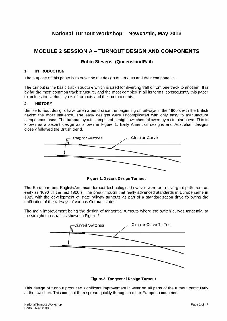
Simple turnout designs have been around since the beginning of railways in the 1800‟s with the British having the most influence. The early designs were uncomplicated with only easy to manufacture components used. The turnout layouts comprised straight switches followed by a circular curve. This is known as a secant design as shown in Figure 1. Early American designs and Australian designs closely followed the British trend.
Straight Switches Circular Curve
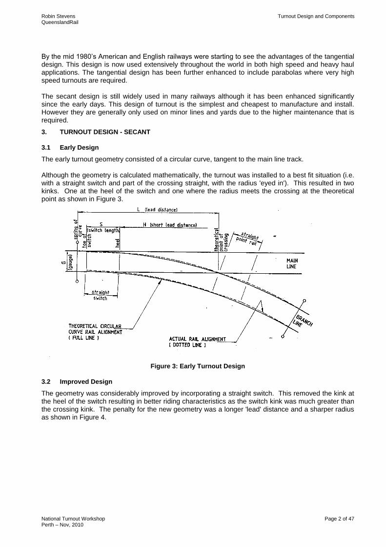
Figure 1: Secant Design Turnout The European and English/American turnout technologies however were on a divergent path from as early as 1890 till the mid 1980‟s. The breakthrough that really advanced standards in Europe came in 1925 with the development of state railway turnouts as part of a standardization drive following the unification of the railways of various German states. The main improvement being the design of tangential turnouts where the switch curves tangential to the straight stock rail as shown in Figure 2.
Circular Curve To ToeCurved Switches
Figure.2: Tangential Design Turnout
This design of turnout produced significant improvement in wear on all parts of the turnout particularly at the switches. This concept then spread quickly through to other European countries.
Robin Stevens Turnout Design and Components QueenslandRail
National Turnout Workshop Page 2 of 47 Perth – Nov, 2010
By the mid 1980‟s American and English railways were starting to see the advantages of the tangential design. This design is now used extensively throughout the world in both high speed and heavy haul applications. The tangential design has been further enhanced to include parabolas where very high speed turnouts are required. The secant design is still widely used in many railways although it has been enhanced significantly since the early days. This design of turnout is the simplest and cheapest to manufacture and install. However they are generally only used on minor lines and yards due to the higher maintenance that is required.
3. TURNOUT DESIGN - SECANT
3.1 Early Design
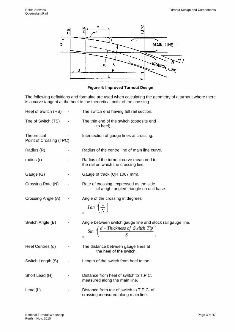
The early turnout geometry consisted of a circular curve, tangent to the main line track. Although the geometry is calculated mathematically, the turnout was installed to a best fit situation (i.e. with a straight switch and part of the crossing straight, with the radius 'eyed in'). This resulted in two kinks. One at the heel of the switch and one where the radius meets the crossing at the theoretical point as shown in Figure 3.
Figure 3: Early Turnout Design
3.2 Improved Design
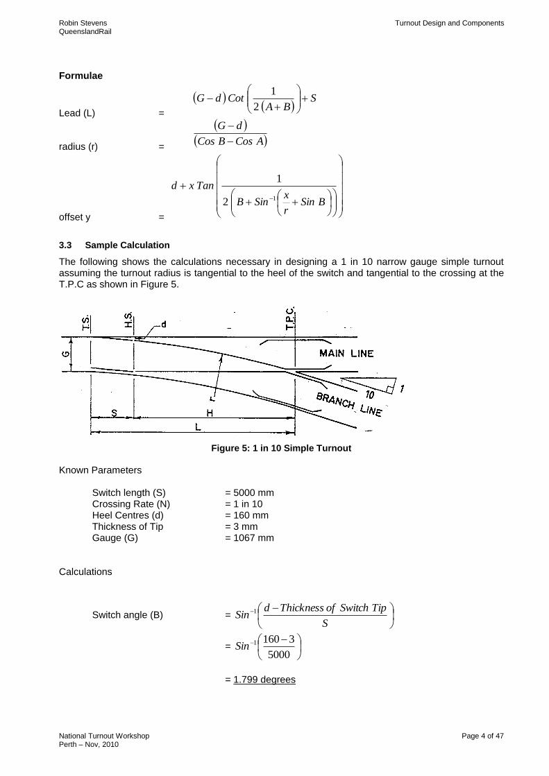
The geometry was considerably improved by incorporating a straight switch. This removed the kink at the heel of the switch resulting in better riding characteristics as the switch kink was much greater than the crossing kink. The penalty for the new geometry was a longer 'lead' distance and a sharper radius as shown in Figure 4.
Robin Stevens Turnout Design and Components QueenslandRail
National Turnout Workshop Page 3 of 47 Perth – Nov, 2010
Figure 4: Improved Turnout Design
The following definitions and formulae are used when calculating the geometry of a turnout where there is a curve tangent at the heel to the theoretical point of the crossing. Heel of Switch (HS) - The switch end having full rail section. Toe of Switch (TS) - The thin end of the switch (opposite end to heel). Theoretical - Intersection of gauge lines at crossing. Point of Crossing (TPC) Radius (R) - Radius of the centre line of main line curve. radius (r) - Radius of the turnout curve measured to the rail on which the crossing lies. Gauge (G) - Gauge of track (QR 1067 mm). Crossing Rate (N) - Rate of crossing, expressed as the side of a right angled triangle on unit base. Crossing Angle (A) - Angle of the crossing in degrees
=
NTan
11
Switch Angle (B) - Angle between switch gauge line and stock rail gauge line.
=
S
TipSwitchofThicknessdSin 1
Heel Centres (d) - The distance between gauge lines at the heel of the switch. Switch Length (S) - Length of the switch from heel to toe. Short Lead (H) - Distance from heel of switch to T.P.C. measured along the main line. Lead (L) - Distance from toe of switch to T.P.C. of crossing measured along main line.
Robin Stevens Turnout Design and Components QueenslandRail
National Turnout Workshop Page 4 of 47 Perth – Nov, 2010
Formulae
Lead (L) =
SBA
CotdG
2
1
radius (r) =
ACosBCos
dG
offset y =
BSin
r
xSinB
Tanxd12
1
3.3 Sample Calculation
The following shows the calculations necessary in designing a 1 in 10 narrow gauge simple turnout assuming the turnout radius is tangential to the heel of the switch and tangential to the crossing at the T.P.C as shown in Figure 5.
Figure 5: 1 in 10 Simple Turnout
Known Parameters Switch length (S) = 5000 mm Crossing Rate (N) = 1 in 10 Heel Centres (d) = 160 mm Thickness of Tip = 3 mm Gauge (G) = 1067 mm Calculations
Switch angle (B) =
S
TipSwitchofThicknessdSin 1
=
5000
31601Sin
= 1.799 degrees
Robin Stevens Turnout Design and Components QueenslandRail
National Turnout Workshop Page 5 of 47 Perth – Nov, 2010
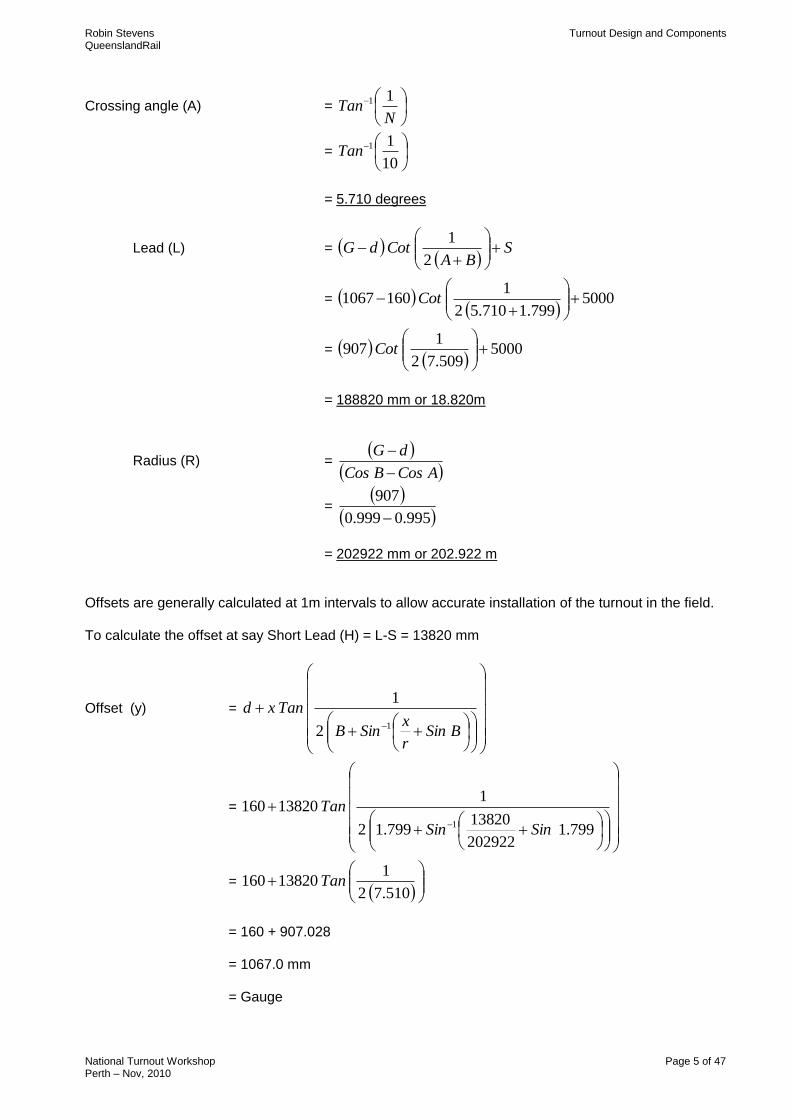
Crossing angle (A) =
NTan
11
=
10
11Tan
= 5.710 degrees
Lead (L) =
SBA
CotdG
2
1
=
5000799.1710.52
11601067
Cot
=
5000509.72
1907
Cot
= 188820 mm or 18.820m
Radius (R) =
ACosBCos
dG
=
995.0999.0
907
= 202922 mm or 202.922 m
Offsets are generally calculated at 1m intervals to allow accurate installation of the turnout in the field. To calculate the offset at say Short Lead (H) = L-S = 13820 mm
Offset (y) =
BSin
r
xSinB
Tanxd12
1
=
799.1
202922
13820799.12
113820160
1 SinSin
Tan
=
510.72
113820160 Tan
= 160 + 907.028
= 1067.0 mm = Gauge
Robin Stevens Turnout Design and Components QueenslandRail
National Turnout Workshop Page 6 of 47 Perth – Nov, 2010
3.4 Latest Design
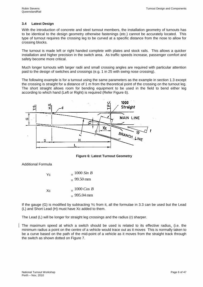
With the introduction of concrete and steel turnout members, the installation geometry of turnouts has to be identical to the design geometry otherwise fastenings (etc.) cannot be accurately located. This type of turnout requires the crossing leg to be curved at a specific distance from the nose to allow for crossing blocks. The turnout is made left or right handed complete with plates and stock rails. This allows a quicker installation and higher precision in the switch area. As traffic speeds increase, passenger comfort and safety become more critical. Much longer turnouts with larger radii and small crossing angles are required with particular attention paid to the design of switches and crossings (e.g. 1 in 25 with swing nose crossing). The following example is for a turnout using the same parameters as the example in section 1.3 except the crossing is straight for a distance of 1 m from the theoretical point of the crossing on the turnout leg. The short straight allows room for bending equipment to be used in the field to bend either leg according to which hand (Left or Right) is required (Refer Figure 6).
Figure 6: Latest Turnout Geometry
Additional Formula
Yc = BSin1000
= mm 99.50
Xc = BCos1000
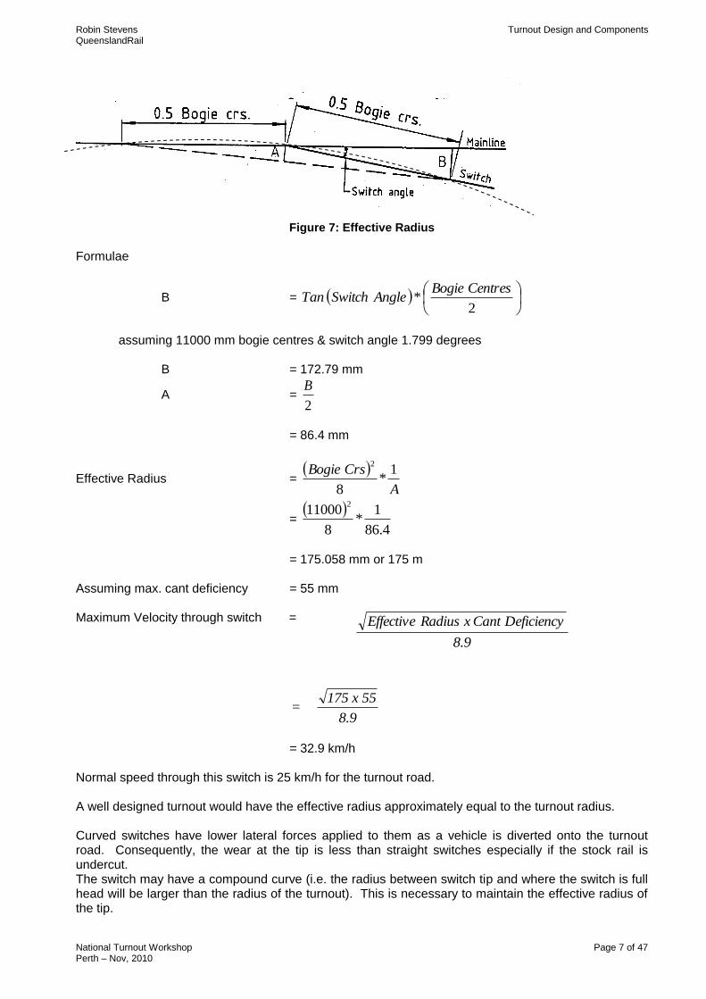
= mm 995.04 If the gauge (G) is modified by subtracting Yc from it, all the formulae in 3.3 can be used but the Lead (L) and Short Lead (H) must have Xc added to them. The Lead (L) will be longer for straight leg crossings and the radius (r) sharper. The maximum speed at which a switch should be used is related to its effective radius. (i.e. the minimum radius a point on the centre of a vehicle would trace out as it moves This is normally taken to be a curve based on the path of the mid-point of a vehicle as it moves from the straight track through the switch as shown dotted on Figure 7.
Robin Stevens Turnout Design and Components QueenslandRail
National Turnout Workshop Page 7 of 47 Perth – Nov, 2010
Figure 7: Effective Radius
Formulae
B =
2*
CentresBogieAngleSwitchTan
assuming 11000 mm bogie centres & switch angle 1.799 degrees
B = 172.79 mm
A = 2
B
= 86.4 mm
Effective Radius =
A
CrsBogie 1*
8
2
=
4.86
1*
8
110002
= 175.058 mm or 175 m
Assuming max. cant deficiency = 55 mm Maximum Velocity through switch =
= 32.9 km/h Normal speed through this switch is 25 km/h for the turnout road. A well designed turnout would have the effective radius approximately equal to the turnout radius. Curved switches have lower lateral forces applied to them as a vehicle is diverted onto the turnout road. Consequently, the wear at the tip is less than straight switches especially if the stock rail is undercut. The switch may have a compound curve (i.e. the radius between switch tip and where the switch is full head will be larger than the radius of the turnout). This is necessary to maintain the effective radius of the tip.
8.9
Deficiency Cant x Radius Effective
= 175 x 55
8.9
Robin Stevens Turnout Design and Components QueenslandRail
National Turnout Workshop Page 8 of 47 Perth – Nov, 2010
4. TURNOUT DESIGN - TANGENTIAL
Turnouts with geometrics different from the standard designs have been in use for many years in other parts of the world. With tangential designs the switch entry angle of these tangents are significantly smaller than the angles in standard turnouts. This translates to less wear at the switch points and a reduction in turnout maintenance. Tangential turnouts generally incorporate asymmetric switches. By using this type of switch section the stock rail is able to be elastic fastened on both sides. The disadvantage of using this section is that the heel end of the switch must be forged then flash butt welded to standard rail section.
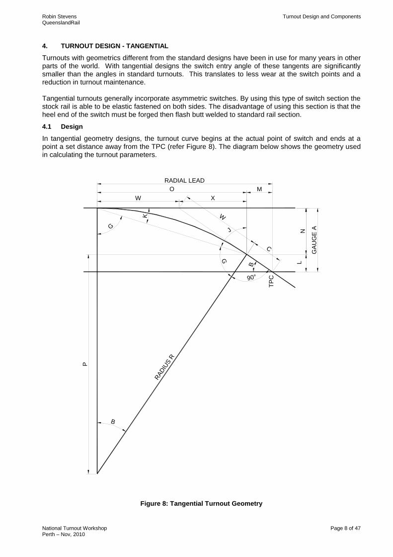
4.1 Design
In tangential geometry designs, the turnout curve begins at the actual point of switch and ends at a point a set distance away from the TPC (refer Figure 8). The diagram below shows the geometry used in calculating the turnout parameters.
LN
RAD
IUS R
WK
GJ
G
90°
B
RADIAL LEAD
X
O
W
GA
UG
E A
M
B
C
P
TP
C
Figure 8: Tangential Turnout Geometry
Robin Stevens Turnout Design and Components QueenslandRail
National Turnout Workshop Page 9 of 47 Perth – Nov, 2010
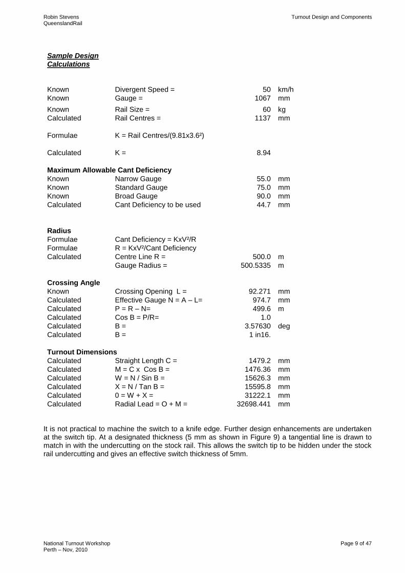
Sample Design Calculations
Known Divergent Speed = 50 km/h
Known Gauge = 1067 mm
Known Rail Size = 60 kg
Calculated Rail Centres = 1137 mm
Formulae K = Rail Centres/(9.81x3.6²)
Calculated K = 8.94
Maximum Allowable Cant Deficiency
Known Narrow Gauge 55.0 mm
Known Standard Gauge 75.0 mm
Known Broad Gauge 90.0 mm
Calculated Cant Deficiency to be used 44.7 mm
Radius
Formulae Cant Deficiency = KxV²/R
Formulae R = KxV²/Cant Deficiency
Calculated Centre Line R = 500.0 m
Gauge Radius = 500.5335 m
Crossing Angle
Known Crossing Opening L = 92.271 mm
Calculated Effective Gauge N = A – L= 974.7 mm
Calculated P = R – N= 499.6 m
Calculated Cos B = P/R= 1.0
Calculated B = 3.57630 deg
Calculated B = 1 in16.
Turnout Dimensions
Calculated Straight Length C = 1479.2 mm
Calculated M = C x Cos B = 1476.36 mm
Calculated W = N / Sin B = 15626.3 mm
Calculated X = N / Tan B = 15595.8 mm
Calculated 0 = W + X = 31222.1 mm
Calculated Radial Lead = O + M = 32698.441 mm
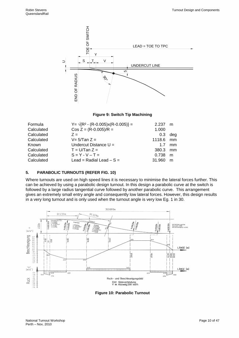
It is not practical to machine the switch to a knife edge. Further design enhancements are undertaken at the switch tip. At a designated thickness (5 mm as shown in Figure 9) a tangential line is drawn to match in with the undercutting on the stock rail. This allows the switch tip to be hidden under the stock rail undercutting and gives an effective switch thickness of 5mm.
Robin Stevens Turnout Design and Components QueenslandRail
National Turnout Workshop Page 10 of 47 Perth – Nov, 2010
5
UNDERCUT LINE
90°
Y
S VTU
TO
E O
F S
WIT
CH
EN
D O
F R
AD
IUS
LEAD = TOE TO TPC
Figure 9: Switch Tip Machining
Formula Y= √{R² - (R-0.005)x(R-0.005)} = 2.237 m
Calculated Cos Z = (R-0.005)/R = 1.000
Calculated Z = 0.3 deg
Calculated V= 5/Tan Z = 1118.6 mm
Known Undercut Distance U = 1.7 mm
Calculated T = U/Tan Z = 380.3 mm
Calculated S = Y - V – T = 0.738 m
Calculated Lead = Radial Lead – S = 31.960 m
5. PARABOLIC TURNOUTS (REFER FIG. 10)
Where turnouts are used on high speed lines it is necessary to minimise the lateral forces further. This can be achieved by using a parabolic design turnout. In this design a parabolic curve at the switch is followed by a large radius tangential curve followed by another parabolic curve. This arrangement gives an extremely small entry angle and consequently low lateral forces. However, this design results in a very long turnout and is only used when the turnout angle is very low Eg. 1 in 30.
Figure 10: Parabolic Turnout
Robin Stevens Turnout Design and Components QueenslandRail
National Turnout Workshop Page 11 of 47 Perth – Nov, 2010
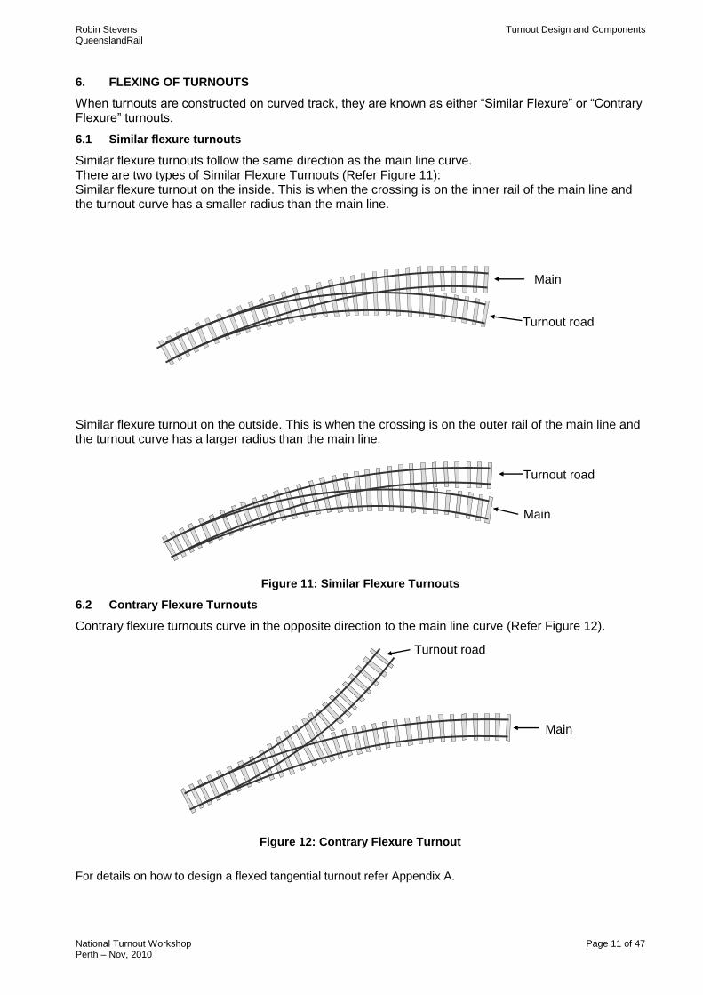
6. FLEXING OF TURNOUTS
When turnouts are constructed on curved track, they are known as either “Similar Flexure” or “Contrary Flexure” turnouts.
6.1 Similar flexure turnouts
Similar flexure turnouts follow the same direction as the main line curve. There are two types of Similar Flexure Turnouts (Refer Figure 11): Similar flexure turnout on the inside. This is when the crossing is on the inner rail of the main line and the turnout curve has a smaller radius than the main line.
Similar flexure turnout on the outside. This is when the crossing is on the outer rail of the main line and the turnout curve has a larger radius than the main line.
Figure 11: Similar Flexure Turnouts
6.2 Contrary Flexure Turnouts
Contrary flexure turnouts curve in the opposite direction to the main line curve (Refer Figure 12).
Figure 12: Contrary Flexure Turnout
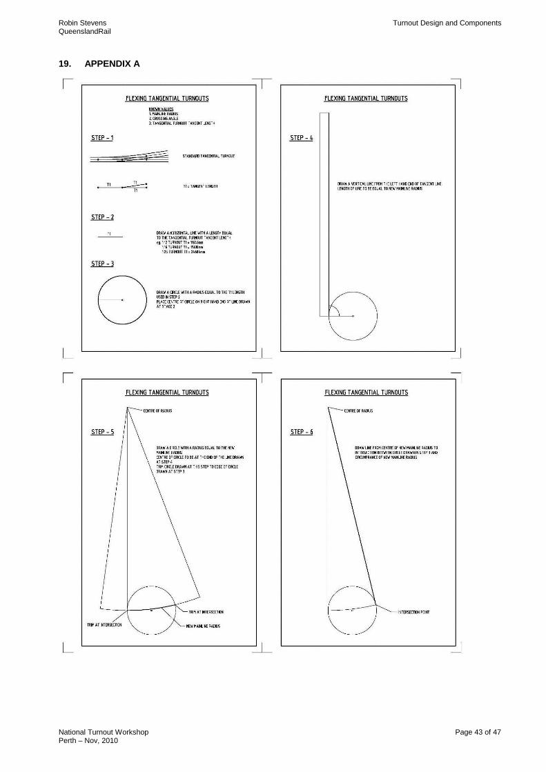
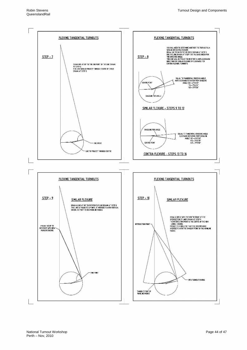
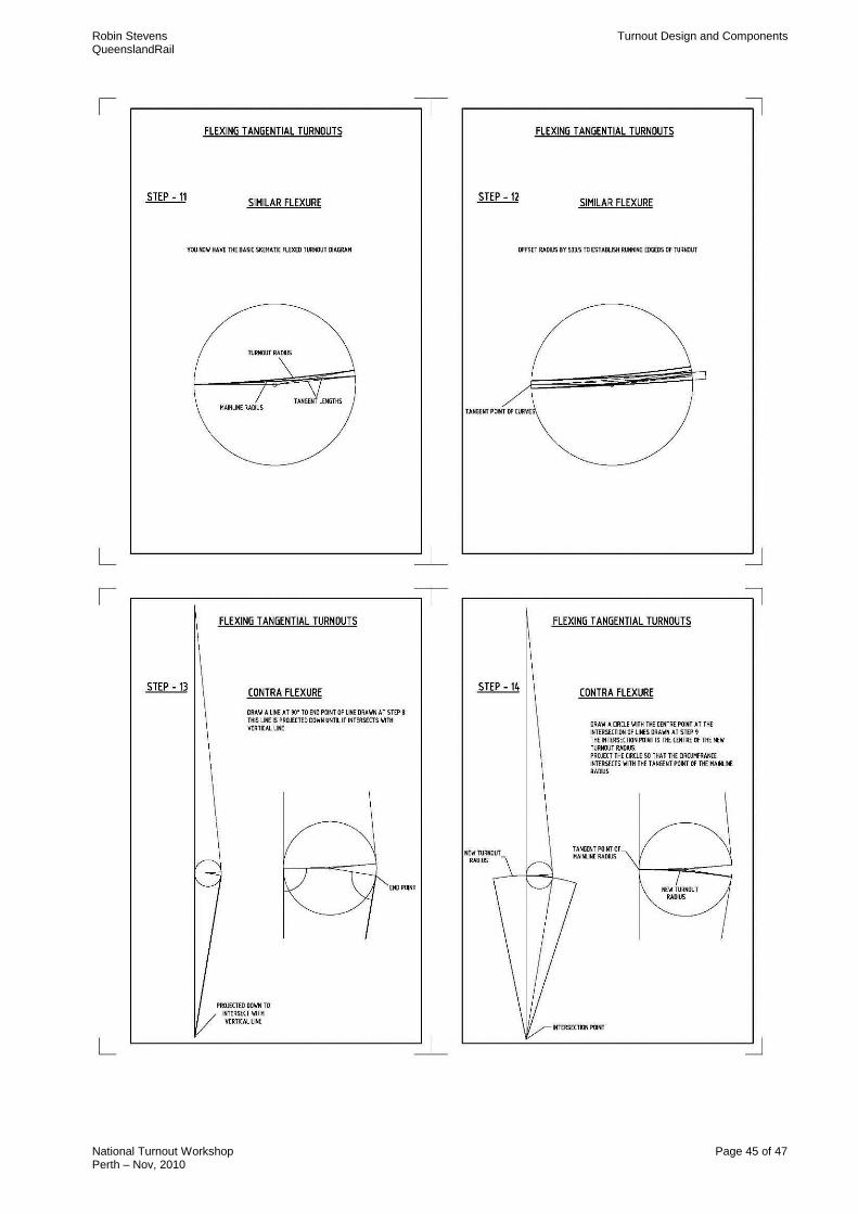
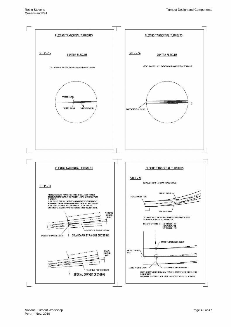
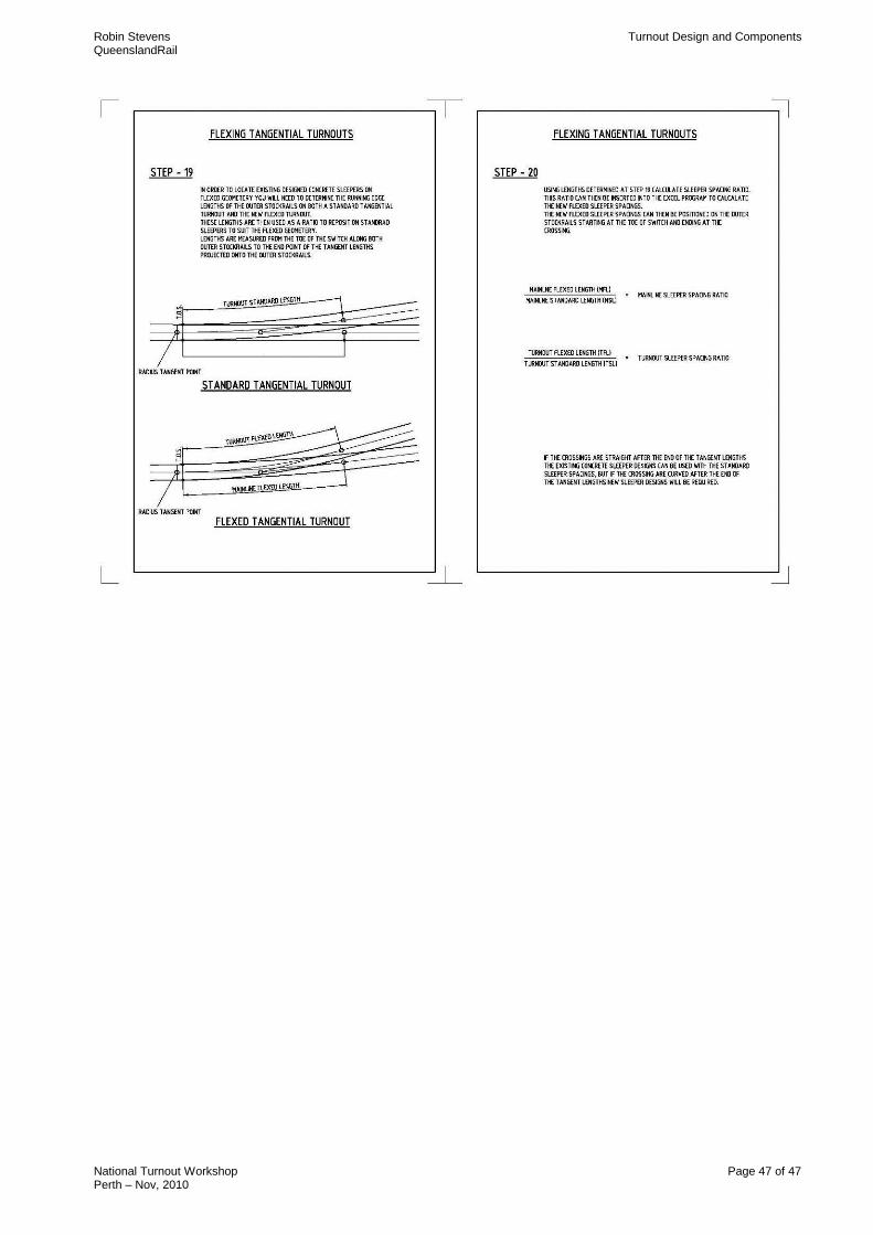
For details on how to design a flexed tangential turnout refer Appendix A.
Main
Turnout road
Main
Turnout road
Main
Turnout road
Robin Stevens Turnout Design and Components QueenslandRail
National Turnout Workshop Page 12 of 47 Perth – Nov, 2010
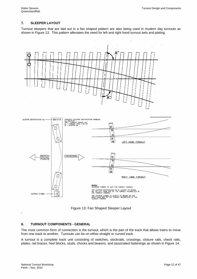
7. SLEEPER LAYOUT
Turnout sleepers that are laid out in a fan shaped pattern are also being used in modern day turnouts as shown in Figure 13. This pattern alleviates the need for left and right hand turnout sets and plating.
Figure 13: Fan Shaped Sleeper Layout .
8. TURNOUT COMPONENTS - GENERAL
The most common form of connection is the turnout, which is the part of the track that allows trains to move from one track to another. Turnouts can be on either straight or curved track.
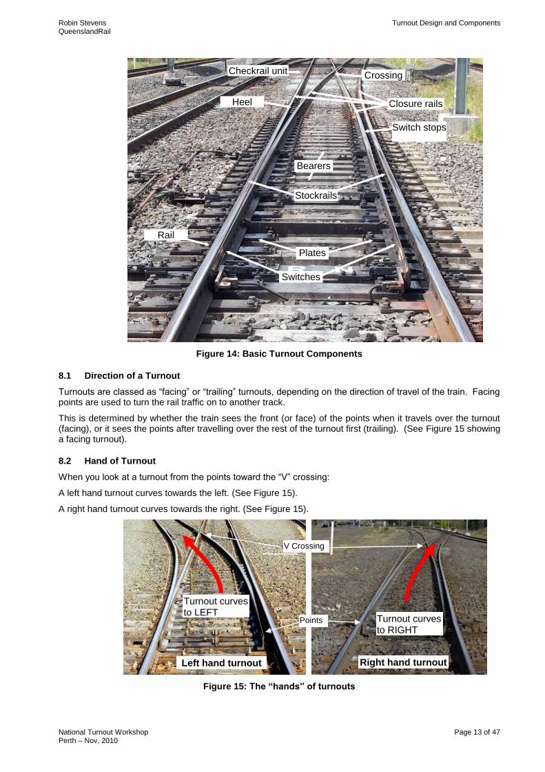
A turnout is a complete track unit consisting of switches, stockrails, crossings, closure rails, check rails, plates, rail braces, heel blocks, studs, chocks and bearers, and associated fastenings as shown in Figure 14.
Robin Stevens Turnout Design and Components QueenslandRail
National Turnout Workshop Page 13 of 47 Perth – Nov, 2010
Figure 14: Basic Turnout Components
8.1 Direction of a Turnout
Turnouts are classed as “facing” or “trailing” turnouts, depending on the direction of travel of the train. Facing points are used to turn the rail traffic on to another track.
This is determined by whether the train sees the front (or face) of the points when it travels over the turnout (facing), or it sees the points after travelling over the rest of the turnout first (trailing). (See Figure 15 showing a facing turnout).
8.2 Hand of Turnout
When you look at a turnout from the points toward the “V” crossing:
A left hand turnout curves towards the left. (See Figure 15).
A right hand turnout curves towards the right. (See Figure 15).
Figure 15: The “hands” of turnouts
Heel block
Rail Brace
Checkrail unit
Closure rails
Crossing
Bearers
Switches
Plates
Switch stops
Stockrails
Turnout curves to LEFT
Turnout curves to RIGHT
Right hand turnout Left hand turnout
V Crossing
Points
Robin Stevens Turnout Design and Components QueenslandRail
National Turnout Workshop Page 14 of 47 Perth – Nov, 2010
9. SWITCHES
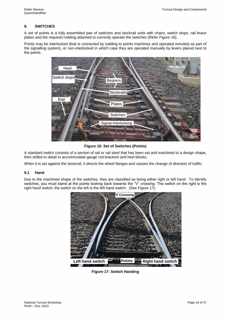
A set of points is a fully assembled pair of switches and stockrail units with chairs, switch stops, rail brace plates and the required rodding attached to correctly operate the switches (Refer Figure 16).
Points may be interlocked (that is connected by rodding to points machines and operated remotely as part of the signalling system), or non-interlocked in which case they are operated manually by levers placed next to the points.
Figure 16: Set of Switches (Points)
A standard switch consists of a section of rail or rail steel that has been set and machined to a design shape, then drilled to detail to accommodate gauge rod brackets and heel blocks.
When it is set against the stockrail, it directs the wheel flanges and causes the change of direction of traffic.
9.1 Hand
Due to the machined shape of the switches, they are classified as being either right or left hand. To identify switches, you must stand at the points looking back towards the “V” crossing. The switch on the right is the right hand switch; the switch on the left is the left hand switch. (See Figure 17).
Figure 17: Switch Handing
Rail Brace
Bearers
Switches
Plates
Stockrails
Heel block
Switch stops
Signal Interlocking
Right hand switch Left hand switch
V Crossing
Points
Robin Stevens Turnout Design and Components QueenslandRail
National Turnout Workshop Page 15 of 47 Perth – Nov, 2010
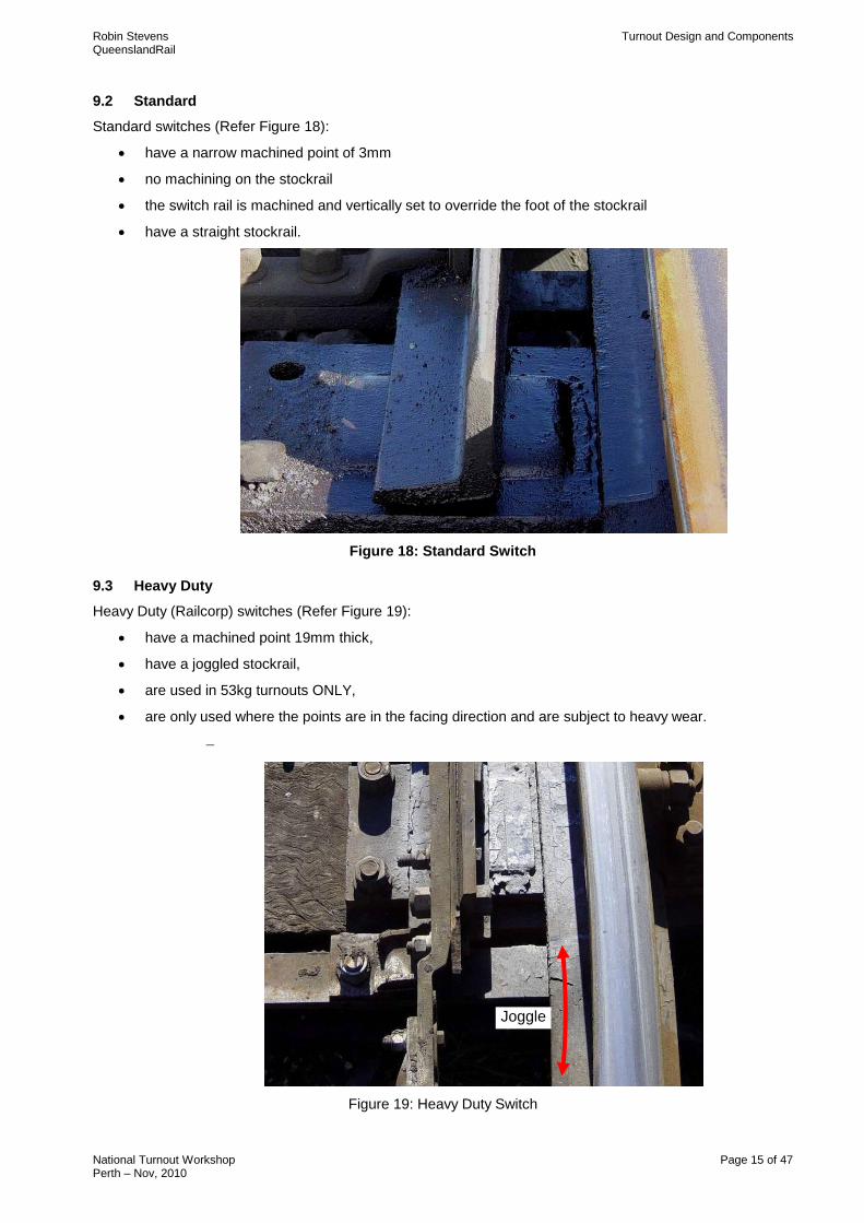
9.2 Standard
Standard switches (Refer Figure 18):
have a narrow machined point of 3mm
no machining on the stockrail
the switch rail is machined and vertically set to override the foot of the stockrail
have a straight stockrail.
Figure 18: Standard Switch
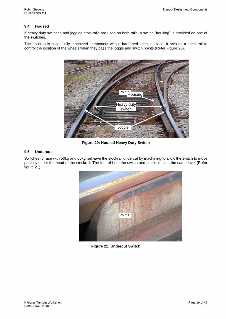
9.3 Heavy Duty
Heavy Duty (Railcorp) switches (Refer Figure 19):
have a machined point 19mm thick,
have a joggled stockrail,
are used in 53kg turnouts ONLY,
are only used where the points are in the facing direction and are subject to heavy wear.
Figure 19: Heavy Duty Switch
Joggle
Robin Stevens Turnout Design and Components QueenslandRail
National Turnout Workshop Page 16 of 47 Perth – Nov, 2010
9.4 Housed
If heavy duty switches and joggled stockrails are used on both rails, a switch “housing” is provided on one of the switches.
The housing is a specially machined component with a hardened checking face. It acts as a checkrail to control the position of the wheels when they pass the joggle and switch points (Refer Figure 20).
Figure 20: Housed Heavy Duty Switch
9.5 Undercut
Switches for use with 50kg and 60kg rail have the stockrail undercut by machining to allow the switch to move partially under the head of the stockrail. The foot of both the switch and stockrail sit at the same level (Refer figure 21).
Figure 21: Undercut Switch
Points Housing
Joggle
Heavy duty switch
Points
Robin Stevens Turnout Design and Components QueenslandRail
National Turnout Workshop Page 17 of 47 Perth – Nov, 2010
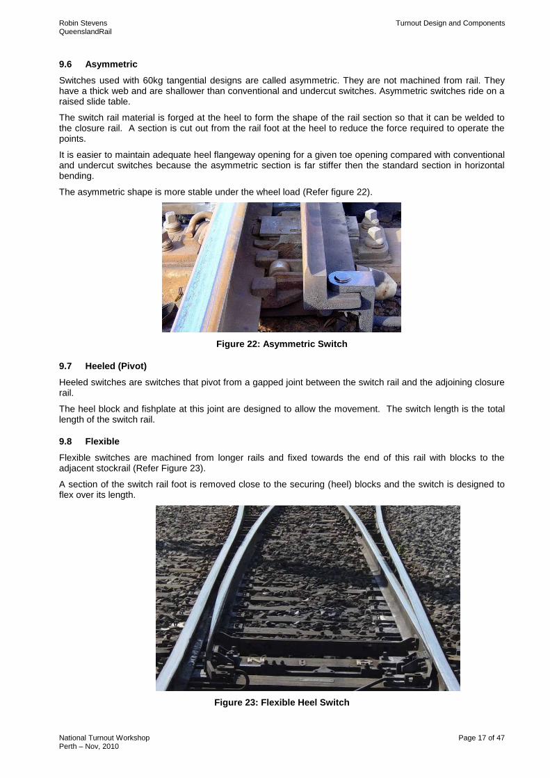
9.6 Asymmetric
Switches used with 60kg tangential designs are called asymmetric. They are not machined from rail. They have a thick web and are shallower than conventional and undercut switches. Asymmetric switches ride on a raised slide table.
The switch rail material is forged at the heel to form the shape of the rail section so that it can be welded to the closure rail. A section is cut out from the rail foot at the heel to reduce the force required to operate the points.
It is easier to maintain adequate heel flangeway opening for a given toe opening compared with conventional and undercut switches because the asymmetric section is far stiffer then the standard section in horizontal bending.
The asymmetric shape is more stable under the wheel load (Refer figure 22).
Figure 22: Asymmetric Switch
9.7 Heeled (Pivot)
Heeled switches are switches that pivot from a gapped joint between the switch rail and the adjoining closure rail.
The heel block and fishplate at this joint are designed to allow the movement. The switch length is the total length of the switch rail.
9.8 Flexible
Flexible switches are machined from longer rails and fixed towards the end of this rail with blocks to the adjacent stockrail (Refer Figure 23).
A section of the switch rail foot is removed close to the securing (heel) blocks and the switch is designed to flex over its length.
Figure 23: Flexible Heel Switch
Robin Stevens Turnout Design and Components QueenslandRail
National Turnout Workshop Page 18 of 47 Perth – Nov, 2010
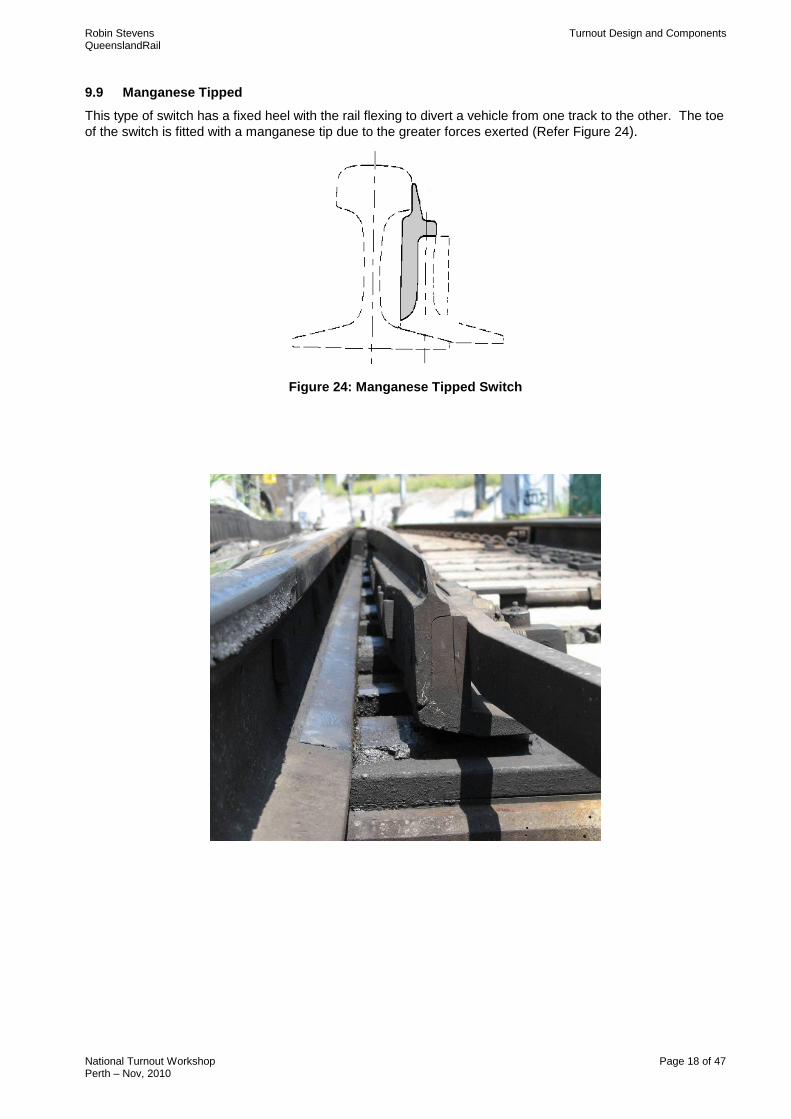
9.9 Manganese Tipped
This type of switch has a fixed heel with the rail flexing to divert a vehicle from one track to the other. The toe
of the switch is fitted with a manganese tip due to the greater forces exerted (Refer Figure 24).
Figure 24: Manganese Tipped Switch
Robin Stevens Turnout Design and Components QueenslandRail
National Turnout Workshop Page 19 of 47 Perth – Nov, 2010
10. SWITCH AND STOCKRAIL
The other area where there is a complex interface between wheel and rail is through the switch area. There are three issues to be considered.
Protection of the switch tip
Load transfer between switch and stockrail
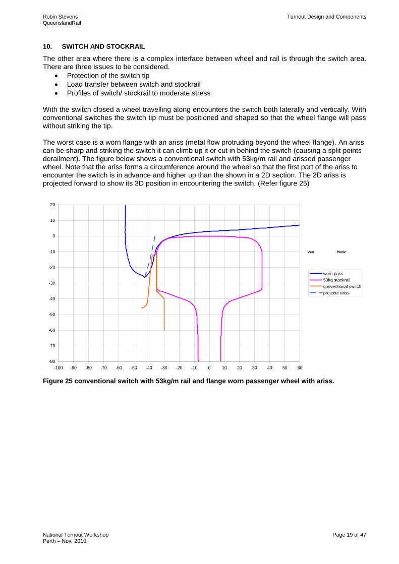
Profiles of switch/ stockrail to moderate stress With the switch closed a wheel travelling along encounters the switch both laterally and vertically. With conventional switches the switch tip must be positioned and shaped so that the wheel flange will pass without striking the tip. The worst case is a worn flange with an ariss (metal flow protruding beyond the wheel flange). An ariss can be sharp and striking the switch it can climb up it or cut in behind the switch (causing a split points derailment). The figure below shows a conventional switch with 53kg/m rail and arissed passenger wheel. Note that the ariss forms a circumference around the wheel so that the first part of the ariss to encounter the switch is in advance and higher up than the shown in a 2D section. The 2D ariss is projected forward to show its 3D position in encountering the switch. (Refer figure 25) Conventional Switch
-80
-70
-60
-50
-40
-30
-20
-10
0
10
20
-100 -90 -80 -70 -60 -50 -40 -30 -20 -10 0 10 20 30 40 50 60
worn pass
53kg stockrail
conventional switch
projecte ariss
Vert Horiz
Figure 25 conventional switch with 53kg/m rail and flange worn passenger wheel with ariss.
Robin Stevens Turnout Design and Components QueenslandRail
National Turnout Workshop Page 20 of 47 Perth – Nov, 2010
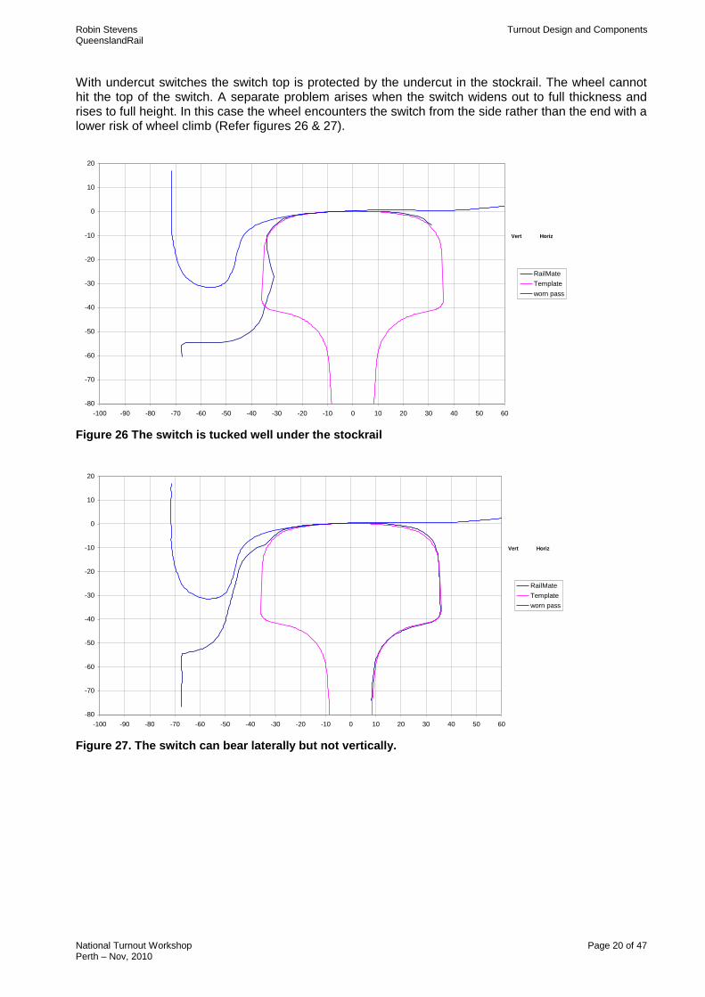
With undercut switches the switch top is protected by the undercut in the stockrail. The wheel cannot hit the top of the switch. A separate problem arises when the switch widens out to full thickness and rises to full height. In this case the wheel encounters the switch from the side rather than the end with a lower risk of wheel climb (Refer figures 26 & 27). 39, revesby, 30, Down
-80
-70
-60
-50
-40
-30
-20
-10
0
10
20
-100 -90 -80 -70 -60 -50 -40 -30 -20 -10 0 10 20 30 40 50 60
RailMate
Template
worn pass
Vert Horiz
Figure 26 The switch is tucked well under the stockrail
47, revesby, 2400, Down
-80
-70
-60
-50
-40
-30
-20
-10
0
10
20
-100 -90 -80 -70 -60 -50 -40 -30 -20 -10 0 10 20 30 40 50 60
RailMate
Template
worn pass
Vert Horiz
Figure 27. The switch can bear laterally but not vertically.
Robin Stevens Turnout Design and Components QueenslandRail
National Turnout Workshop Page 21 of 47 Perth – Nov, 2010
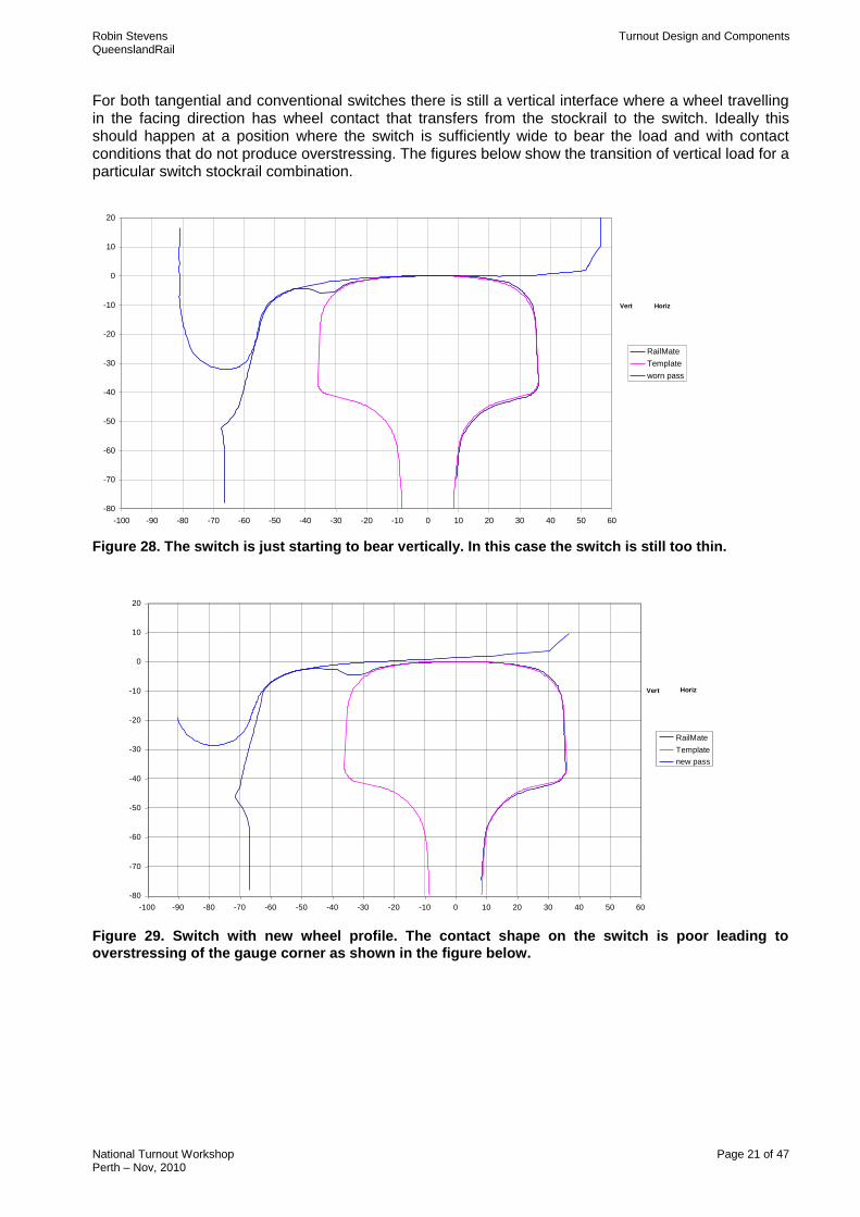
For both tangential and conventional switches there is still a vertical interface where a wheel travelling in the facing direction has wheel contact that transfers from the stockrail to the switch. Ideally this should happen at a position where the switch is sufficiently wide to bear the load and with contact conditions that do not produce overstressing. The figures below show the transition of vertical load for a particular switch stockrail combination. 51, revesby, 3900, Down
-80
-70
-60
-50
-40
-30
-20
-10
0
10
20
-100 -90 -80 -70 -60 -50 -40 -30 -20 -10 0 10 20 30 40 50 60
RailMate
Template
worn pass
Vert Horiz
Figure 28. The switch is just starting to bear vertically. In this case the switch is still too thin.
54, revesby, 4800, Down
-80
-70
-60
-50
-40
-30
-20
-10
0
10
20
-100 -90 -80 -70 -60 -50 -40 -30 -20 -10 0 10 20 30 40 50 60
RailMate
Template
new pass
Vert Horiz
Figure 29. Switch with new wheel profile. The contact shape on the switch is poor leading to
overstressing of the gauge corner as shown in the figure below.
Robin Stevens Turnout Design and Components QueenslandRail
National Turnout Workshop Page 22 of 47 Perth – Nov, 2010
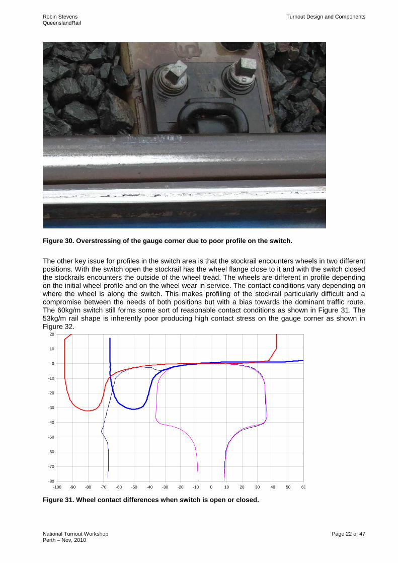
Figure 30. Overstressing of the gauge corner due to poor profile on the switch.
The other key issue for profiles in the switch area is that the stockrail encounters wheels in two different positions. With the switch open the stockrail has the wheel flange close to it and with the switch closed the stockrails encounters the outside of the wheel tread. The wheels are different in profile depending on the initial wheel profile and on the wheel wear in service. The contact conditions vary depending on where the wheel is along the switch. This makes profiling of the stockrail particularly difficult and a compromise between the needs of both positions but with a bias towards the dominant traffic route. The 60kg/m switch still forms some sort of reasonable contact conditions as shown in Figure 31. The 53kg/m rail shape is inherently poor producing high contact stress on the gauge corner as shown in Figure 32.
Figure 31. Wheel contact differences when switch is open or closed.
54, revesby, 4800, Down
-80
-70
-60
-50
-40
-30
-20
-10
0
10
20
-100 -90 -80 -70 -60 -50 -40 -30 -20 -10 0 10 20 30 40 50 60
RailMate
Template
worn pass
Series4
Vert Horiz
Robin Stevens Turnout Design and Components QueenslandRail
National Turnout Workshop Page 23 of 47 Perth – Nov, 2010
Conventional Switch
-80
-70
-60
-50
-40
-30
-20
-10
0
10
20
-100 -90 -80 -70 -60 -50 -40 -30 -20 -10 0 10 20 30 40 50 60
worn pass
53kg stockrail
conventional switch
Vert Horiz
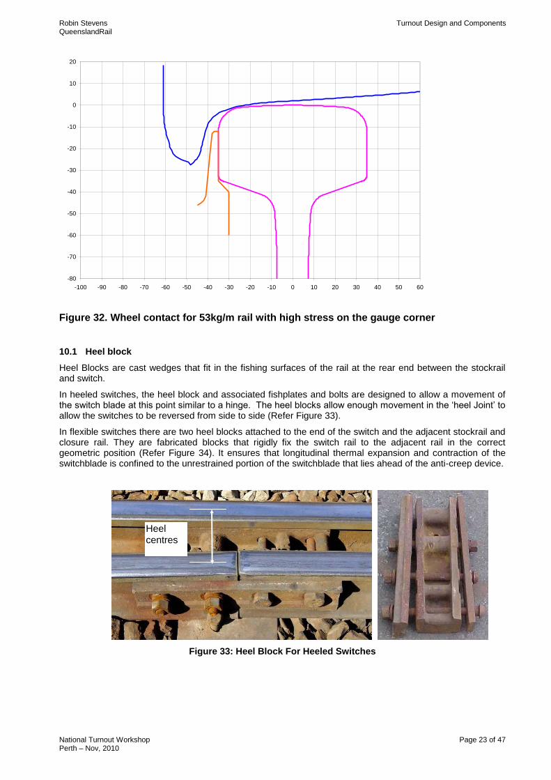
Figure 32. Wheel contact for 53kg/m rail with high stress on the gauge corner
10.1 Heel block
Heel Blocks are cast wedges that fit in the fishing surfaces of the rail at the rear end between the stockrail and switch.
In heeled switches, the heel block and associated fishplates and bolts are designed to allow a movement of the switch blade at this point similar to a hinge. The heel blocks allow enough movement in the „heel Joint‟ to allow the switches to be reversed from side to side (Refer Figure 33).
In flexible switches there are two heel blocks attached to the end of the switch and the adjacent stockrail and closure rail. They are fabricated blocks that rigidly fix the switch rail to the adjacent rail in the correct geometric position (Refer Figure 34). It ensures that longitudinal thermal expansion and contraction of the switchblade is confined to the unrestrained portion of the switchblade that lies ahead of the anti-creep device.
Figure 33: Heel Block For Heeled Switches
Heel centres
Robin Stevens Turnout Design and Components QueenslandRail
National Turnout Workshop Page 24 of 47 Perth – Nov, 2010
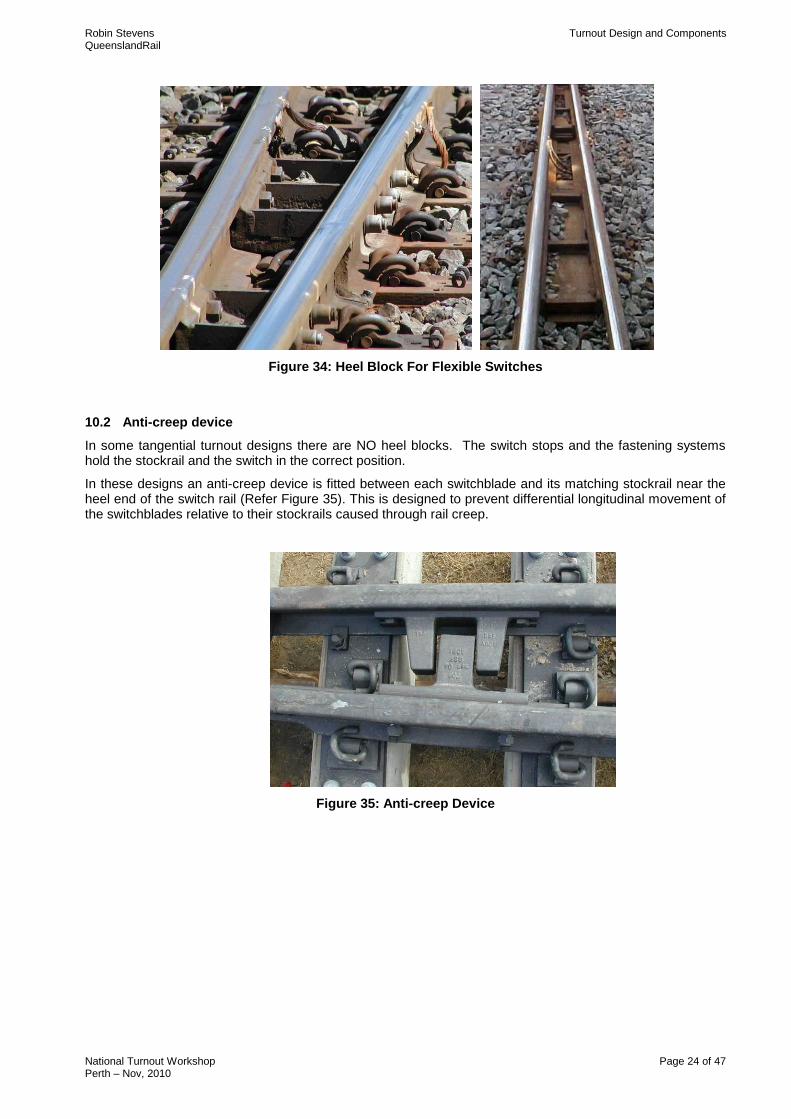
Figure 34: Heel Block For Flexible Switches
10.2 Anti-creep device
In some tangential turnout designs there are NO heel blocks. The switch stops and the fastening systems hold the stockrail and the switch in the correct position.
In these designs an anti-creep device is fitted between each switchblade and its matching stockrail near the heel end of the switch rail (Refer Figure 35). This is designed to prevent differential longitudinal movement of the switchblades relative to their stockrails caused through rail creep.
Figure 35: Anti-creep Device
Robin Stevens Turnout Design and Components QueenslandRail
National Turnout Workshop Page 25 of 47 Perth – Nov, 2010
10.3 Chairs
A chair is a flat plate that is attached with a bolt through the web of the stockrail. Chairs are used to support the points assembly on the bearers. The type of chair is identified by lettering on the end of the plate eg. SR, A, B, C, D.
With undercut switch designs used with 60kg and 50kg switches, the plates are flat under the switch/stockrail.
Asymmetric switches use a different type of fastening and support system. They do not use chairs or rail brace plates.
With the 53kg and 47kg switch designs using standard or heavy duty switches, the plates under the first 3 bearers from the point of the switch have a raised table to support the switch.
When a switch is manufactured, it is bent upwards, or vertically set, to allow more steel to be retained in the foot of the switch while still allowing it to close up correctly.
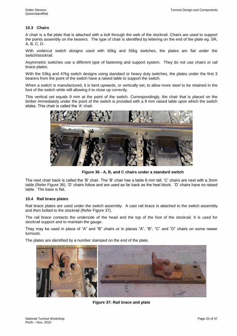
This vertical set equals 9 mm at the point of the switch. Correspondingly, the chair that is placed on the timber immediately under the point of the switch is provided with a 9 mm raised table upon which the switch slides. This chair is called the „A‟ chair.
Figure 36 - A, B, and C chairs under a standard switch
The next chair back is called the „B‟ chair. The „B‟ chair has a table 6 mm tall. „C‟ chairs are next with a 3mm table (Refer Figure 36). „D‟ chairs follow and are used as far back as the heel block. „D‟ chairs have no raised table. The base is flat.
10.4 Rail brace plates
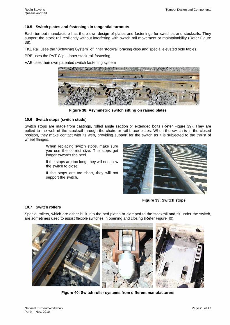
Rail brace plates are used under the switch assembly. A cast rail brace is attached to the switch assembly and then bolted to the stockrail (Refer Figure 37).
The rail brace contacts the underside of the head and the top of the foot of the stockrail. It is used for stockrail support and to maintain the gauge.
They may be used in place of “A” and “B” chairs or in places “A”, “B”, “C” and “D” chairs on some newer turnouts.
The plates are identified by a number stamped on the end of the plate.
Figure 37: Rail brace and plate
Robin Stevens Turnout Design and Components QueenslandRail
National Turnout Workshop Page 26 of 47 Perth – Nov, 2010
10.5 Switch plates and fastenings in tangential turnouts
Each turnout manufacture has there own design of plates and fastenings for switches and stockrails. They support the stock rail resiliently without interfering with switch rail movement or maintainability (Refer Figure 38).
TKL Rail uses the “Schwihag System” of inner stockrail bracing clips and special elevated side tables.
PRE uses the PVT Clip – inner stock rail fastening.
VAE uses their own patented switch fastening system
Figure 38: Asymmetric switch sitting on raised plates
10.6 Switch stops (switch studs)
Switch stops are made from castings, rolled angle section or extended bolts (Refer Figure 39). They are bolted to the web of the stockrail through the chairs or rail brace plates. When the switch is in the closed position, they make contact with its web, providing support for the switch as it is subjected to the thrust of wheel flanges.
When replacing switch stops, make sure you use the correct size. The stops get longer towards the heel.
If the stops are too long, they will not allow the switch to close.
If the stops are too short, they will not support the switch.
Figure 39: Switch stops
10.7 Switch rollers
Special rollers, which are either built into the bed plates or clamped to the stockrail and sit under the switch, are sometimes used to assist flexible switches in opening and closing (Refer Figure 40).
Figure 40: Switch roller systems from different manufacturers
Robin Stevens Turnout Design and Components QueenslandRail
National Turnout Workshop Page 27 of 47 Perth – Nov, 2010
11. CLOSURE RAILS
The closure rails form the remaining portion of the turnout. These rails are crowed to their correct radius before installation and are fastened on flat double shouldered track plates.
The closure rails on the turnout road must be laid with the correct offset from the mainline to ensure the correct radius from the heel block to the “V” crossing.
12. CROSSINGS
12.1 Theoretical point and practical point.
Theoretical point (Refer Figure 41)
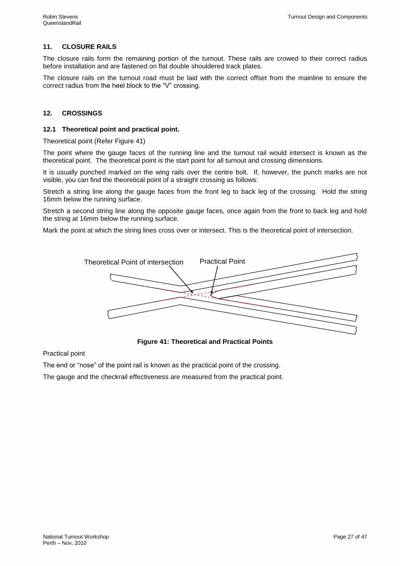
The point where the gauge faces of the running line and the turnout rail would intersect is known as the theoretical point. The theoretical point is the start point for all turnout and crossing dimensions.
It is usually punched marked on the wing rails over the centre bolt. If, however, the punch marks are not visible, you can find the theoretical point of a straight crossing as follows:
Stretch a string line along the gauge faces from the front leg to back leg of the crossing. Hold the string 16mm below the running surface.
Stretch a second string line along the opposite gauge faces, once again from the front to back leg and hold the string at 16mm below the running surface.
Mark the point at which the string lines cross over or intersect. This is the theoretical point of intersection.
Figure 41: Theoretical and Practical Points
Practical point
The end or “nose” of the point rail is known as the practical point of the crossing.
The gauge and the checkrail effectiveness are measured from the practical point.
Practical Point Theoretical Point of intersection
Robin Stevens Turnout Design and Components QueenslandRail
National Turnout Workshop Page 28 of 47 Perth – Nov, 2010
12.2 Crossing rate
The crossing rate is a measure of the angle made by the rail gauge faces at the theoretical point.
The larger the crossing rate, the smaller the angle, the faster the speed through the crossing.
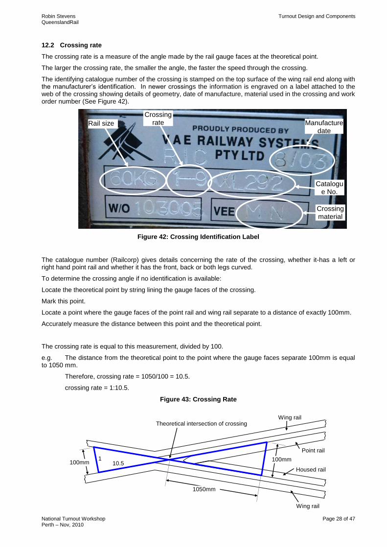
The identifying catalogue number of the crossing is stamped on the top surface of the wing rail end along with the manufacturer‟s identification. In newer crossings the information is engraved on a label attached to the web of the crossing showing details of geometry, date of manufacture, material used in the crossing and work order number (See Figure 42).
Figure 42: Crossing Identification Label
The catalogue number (Railcorp) gives details concerning the rate of the crossing, whether it-has a left or right hand point rail and whether it has the front, back or both legs curved.
To determine the crossing angle if no identification is available:
Locate the theoretical point by string lining the gauge faces of the crossing.
Mark this point.
Locate a point where the gauge faces of the point rail and wing rail separate to a distance of exactly 100mm.
Accurately measure the distance between this point and the theoretical point.
The crossing rate is equal to this measurement, divided by 100.
e.g. The distance from the theoretical point to the point where the gauge faces separate 100mm is equal to 1050 mm.
Therefore, crossing rate = 1050/100 = 10.5.
crossing rate = 1:10.5.
Figure 43: Crossing Rate
100mm 10.5 1 100mm
1050mm
Theoretical intersection of crossing
Housed rail
Point rail
Wing rail
Wing rail
Crossing rate
Catalogue No.
Manufacture date
Crossing material
Rail size
Robin Stevens Turnout Design and Components QueenslandRail
National Turnout Workshop Page 29 of 47 Perth – Nov, 2010
12.3 Type of Crossing
There are 2 types of V crossings
Fixed crossings or Switchable crossings
12.4 Fixed crossings
These crossings have a wheel flange gap in both rails. Wheel transfer of fixed crossings depend on matching wheel and rail profiles. Fixed crossings are used in conjunction with check (guide) rails to provide lateral guidance in the crossing area.
Fixed crossings may be:
Fabricated crossings.
Rail Bound Manganese crossings.
Compound crossings
Fully cast crossings
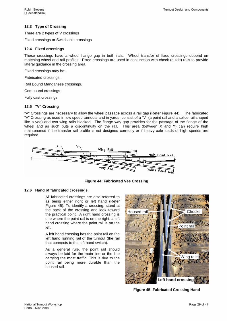
12.5 "V" Crossing
"V" Crossings are necessary to allow the wheel passage across a rail gap (Refer Figure 44) . The fabricated "V" Crossing as used in low speed turnouts and in yards, consist of a "V" (a point rail and a splice rail shaped like a vee) and two wing rails blocked. The flange way gap provides for the passage of the flange of the wheel and as such puts a discontinuity on the rail. This area (between X and Y) can require high maintenance if the transfer rail profile is not designed correctly or if heavy axle loads or high speeds are required.
Figure 44: Fabricated Vee Crossing
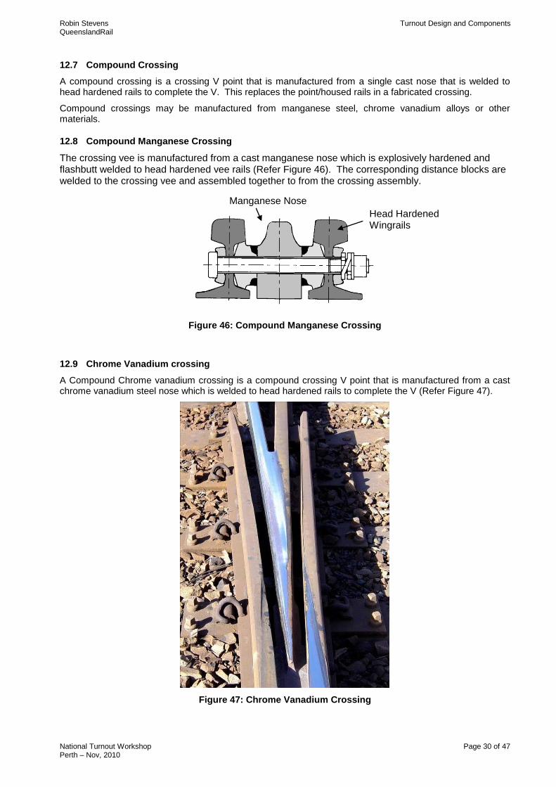
12.6 Hand of fabricated crossings.
All fabricated crossings are also referred to as being either right or left hand (Refer Figure 45). To identify a crossing, stand at the back of the crossing and look toward the practical point. A right hand crossing is one where the point rail is on the right, a left hand crossing where the point rail is on the left.
A left hand crossing has the point rail on the left hand running rail of the turnout (the rail that connects to the left hand switch).
As a general rule, the point rail should always be laid for the main line or the line carrying the most traffic. This is due to the point rail being more durable than the housed rail.
Figure 45: Fabricated Crossing Hand
Point rail
Housed rail
Wing rails rail
Chocks
Left hand crossing
Robin Stevens Turnout Design and Components QueenslandRail
National Turnout Workshop Page 30 of 47 Perth – Nov, 2010
12.7 Compound Crossing
A compound crossing is a crossing V point that is manufactured from a single cast nose that is welded to head hardened rails to complete the V. This replaces the point/housed rails in a fabricated crossing.
Compound crossings may be manufactured from manganese steel, chrome vanadium alloys or other materials.
12.8 Compound Manganese Crossing
The crossing vee is manufactured from a cast manganese nose which is explosively hardened and flashbutt welded to head hardened vee rails (Refer Figure 46). The corresponding distance blocks are welded to the crossing vee and assembled together to from the crossing assembly.
Figure 46: Compound Manganese Crossing
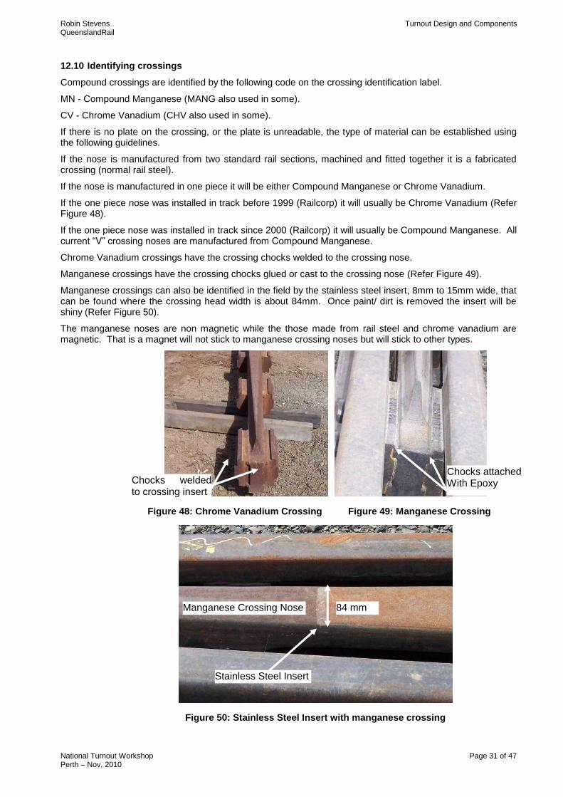
12.9 Chrome Vanadium crossing
A Compound Chrome vanadium crossing is a compound crossing V point that is manufactured from a cast chrome vanadium steel nose which is welded to head hardened rails to complete the V (Refer Figure 47).
Figure 47: Chrome Vanadium Crossing
Head Hardened Wingrails
Manganese Nose
Robin Stevens Turnout Design and Components QueenslandRail
National Turnout Workshop Page 31 of 47 Perth – Nov, 2010
12.10 Identifying crossings
Compound crossings are identified by the following code on the crossing identification label.
MN - Compound Manganese (MANG also used in some).
CV - Chrome Vanadium (CHV also used in some).
If there is no plate on the crossing, or the plate is unreadable, the type of material can be established using the following guidelines.
If the nose is manufactured from two standard rail sections, machined and fitted together it is a fabricated crossing (normal rail steel).
If the nose is manufactured in one piece it will be either Compound Manganese or Chrome Vanadium.
If the one piece nose was installed in track before 1999 (Railcorp) it will usually be Chrome Vanadium (Refer Figure 48).
If the one piece nose was installed in track since 2000 (Railcorp) it will usually be Compound Manganese. All current “V” crossing noses are manufactured from Compound Manganese.
Chrome Vanadium crossings have the crossing chocks welded to the crossing nose.
Manganese crossings have the crossing chocks glued or cast to the crossing nose (Refer Figure 49).
Manganese crossings can also be identified in the field by the stainless steel insert, 8mm to 15mm wide, that can be found where the crossing head width is about 84mm. Once paint/ dirt is removed the insert will be shiny (Refer Figure 50).
The manganese noses are non magnetic while the those made from rail steel and chrome vanadium are magnetic. That is a magnet will not stick to manganese crossing noses but will stick to other types.
Figure 48: Chrome Vanadium Crossing Figure 49: Manganese Crossing
Figure 50: Stainless Steel Insert with manganese crossing
84 mm approx.
Manganese Crossing Nose
Stainless Steel Insert
Chocks attached With Epoxy Chocks welded
to crossing insert
Robin Stevens Turnout Design and Components QueenslandRail
National Turnout Workshop Page 32 of 47 Perth – Nov, 2010
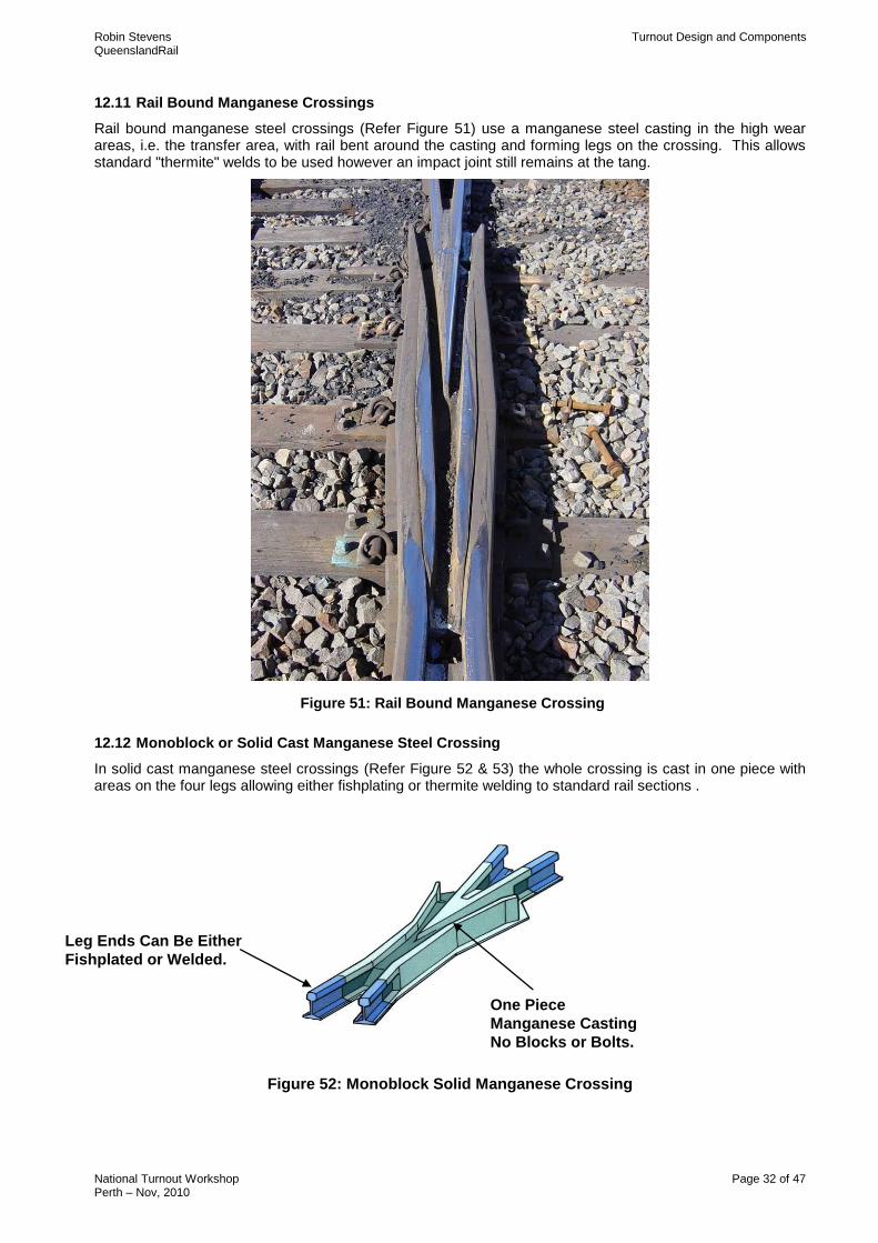
12.11 Rail Bound Manganese Crossings
Rail bound manganese steel crossings (Refer Figure 51) use a manganese steel casting in the high wear areas, i.e. the transfer area, with rail bent around the casting and forming legs on the crossing. This allows standard "thermite" welds to be used however an impact joint still remains at the tang.
Figure 51: Rail Bound Manganese Crossing
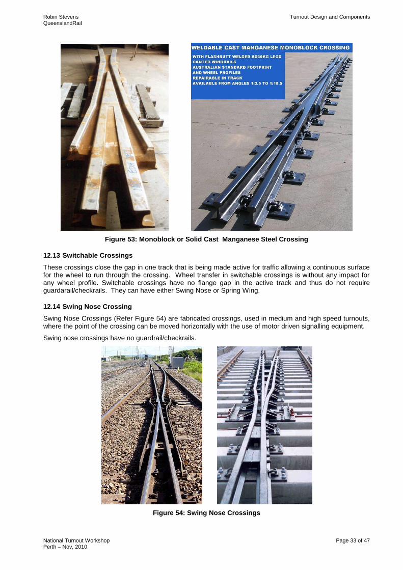
12.12 Monoblock or Solid Cast Manganese Steel Crossing
In solid cast manganese steel crossings (Refer Figure 52 & 53) the whole crossing is cast in one piece with areas on the four legs allowing either fishplating or thermite welding to standard rail sections .
Figure 52: Monoblock Solid Manganese Crossing
One Piece
Manganese Casting
No Blocks or Bolts.
Leg Ends Can Be Either
Fishplated or Welded.
Robin Stevens Turnout Design and Components QueenslandRail
National Turnout Workshop Page 33 of 47 Perth – Nov, 2010
Figure 53: Monoblock or Solid Cast Manganese Steel Crossing
12.13 Switchable Crossings
These crossings close the gap in one track that is being made active for traffic allowing a continuous surface for the wheel to run through the crossing. Wheel transfer in switchable crossings is without any impact for any wheel profile. Switchable crossings have no flange gap in the active track and thus do not require guardarail/checkrails. They can have either Swing Nose or Spring Wing.
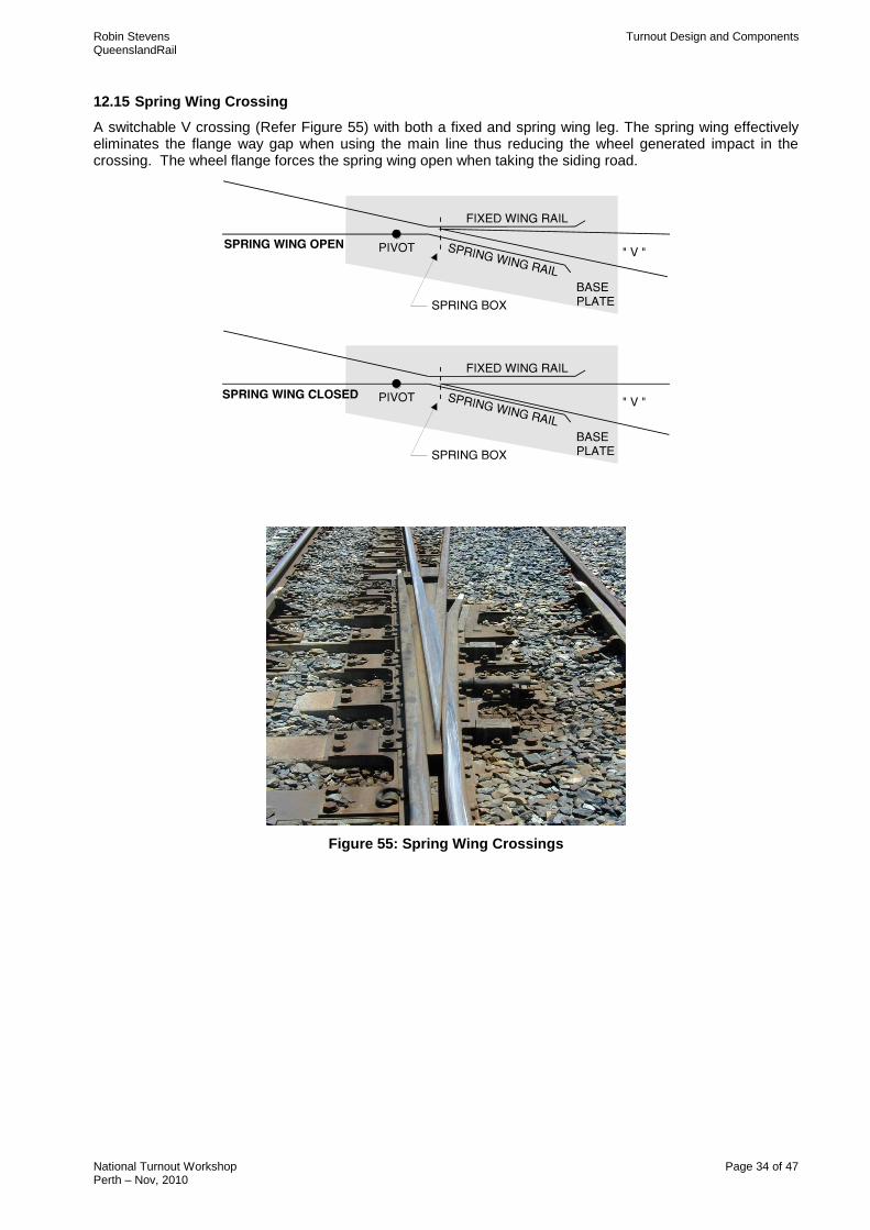
12.14 Swing Nose Crossing
Swing Nose Crossings (Refer Figure 54) are fabricated crossings, used in medium and high speed turnouts, where the point of the crossing can be moved horizontally with the use of motor driven signalling equipment.
Swing nose crossings have no guardrail/checkrails.
Figure 54: Swing Nose Crossings
Robin Stevens Turnout Design and Components QueenslandRail
National Turnout Workshop Page 34 of 47 Perth – Nov, 2010
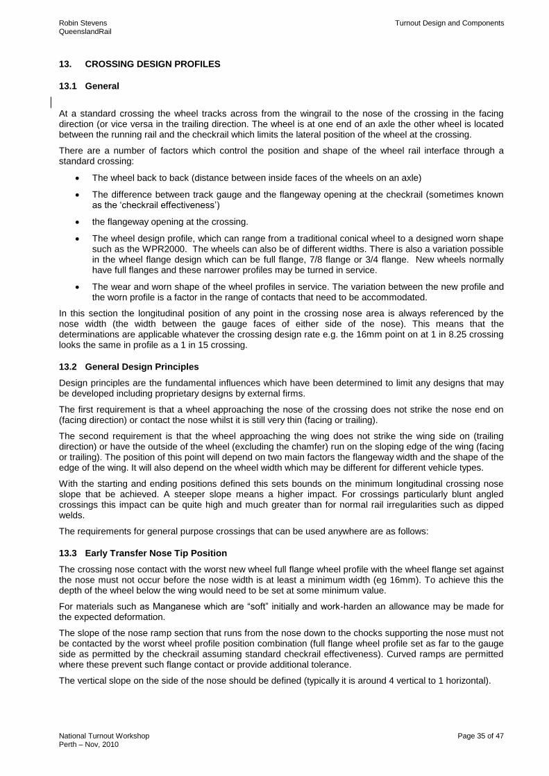
12.15 Spring Wing Crossing
A switchable V crossing (Refer Figure 55) with both a fixed and spring wing leg. The spring wing effectively eliminates the flange way gap when using the main line thus reducing the wheel generated impact in the crossing. The wheel flange forces the spring wing open when taking the siding road.
Figure 55: Spring Wing Crossings
Robin Stevens Turnout Design and Components QueenslandRail
National Turnout Workshop Page 35 of 47 Perth – Nov, 2010
13. CROSSING DESIGN PROFILES
13.1 General
At a standard crossing the wheel tracks across from the wingrail to the nose of the crossing in the facing direction (or vice versa in the trailing direction. The wheel is at one end of an axle the other wheel is located between the running rail and the checkrail which limits the lateral position of the wheel at the crossing.
There are a number of factors which control the position and shape of the wheel rail interface through a standard crossing:
The wheel back to back (distance between inside faces of the wheels on an axle)
The difference between track gauge and the flangeway opening at the checkrail (sometimes known as the „checkrail effectiveness‟)
the flangeway opening at the crossing.
The wheel design profile, which can range from a traditional conical wheel to a designed worn shape such as the WPR2000. The wheels can also be of different widths. There is also a variation possible in the wheel flange design which can be full flange, 7/8 flange or 3/4 flange. New wheels normally have full flanges and these narrower profiles may be turned in service.
The wear and worn shape of the wheel profiles in service. The variation between the new profile and the worn profile is a factor in the range of contacts that need to be accommodated.
In this section the longitudinal position of any point in the crossing nose area is always referenced by the nose width (the width between the gauge faces of either side of the nose). This means that the determinations are applicable whatever the crossing design rate e.g. the 16mm point on at 1 in 8.25 crossing looks the same in profile as a 1 in 15 crossing.
13.2 General Design Principles
Design principles are the fundamental influences which have been determined to limit any designs that may be developed including proprietary designs by external firms.
The first requirement is that a wheel approaching the nose of the crossing does not strike the nose end on (facing direction) or contact the nose whilst it is still very thin (facing or trailing).
The second requirement is that the wheel approaching the wing does not strike the wing side on (trailing direction) or have the outside of the wheel (excluding the chamfer) run on the sloping edge of the wing (facing or trailing). The position of this point will depend on two main factors the flangeway width and the shape of the edge of the wing. It will also depend on the wheel width which may be different for different vehicle types.
With the starting and ending positions defined this sets bounds on the minimum longitudinal crossing nose slope that be achieved. A steeper slope means a higher impact. For crossings particularly blunt angled crossings this impact can be quite high and much greater than for normal rail irregularities such as dipped welds.
The requirements for general purpose crossings that can be used anywhere are as follows:
13.3 Early Transfer Nose Tip Position
The crossing nose contact with the worst new wheel full flange wheel profile with the wheel flange set against the nose must not occur before the nose width is at least a minimum width (eg 16mm). To achieve this the depth of the wheel below the wing would need to be set at some minimum value.
For materials such as Manganese which are “soft” initially and work-harden an allowance may be made for the expected deformation.
The slope of the nose ramp section that runs from the nose down to the chocks supporting the nose must not be contacted by the worst wheel profile position combination (full flange wheel profile set as far to the gauge side as permitted by the checkrail assuming standard checkrail effectiveness). Curved ramps are permitted where these prevent such flange contact or provide additional tolerance.
The vertical slope on the side of the nose should be defined (typically it is around 4 vertical to 1 horizontal).
Robin Stevens Turnout Design and Components QueenslandRail
National Turnout Workshop Page 36 of 47 Perth – Nov, 2010
13.4 Late Transfer Nose to Wing Position
The second requirement is that the wheel approaching the wing does not strike the wing side on (trailing direction) or have the outside of the wheel (excluding the chamfer) run on the sloping edge of the wing (facing or trailing). The position of this point will depend on two main factors the flangeway width and the shape of the edge of the wing. It will also depend on the narrowest wheel and the allowable wear (tread hollowing).
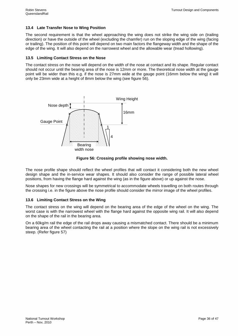
13.5 Limiting Contact Stress on the Nose
The contact stress on the nose will depend on the width of the nose at contact and its shape. Regular contact should not occur until the bearing area of the nose is 12mm or more. The theoretical nose width at the gauge point will be wider than this e.g. if the nose is 27mm wide at the gauge point (16mm below the wing) it will only be 23mm wide at a height of 8mm below the wing (see figure 56).
Figure 56: Crossing profile showing nose width.
The nose profile shape should reflect the wheel profiles that will contact it considering both the new wheel design shape and the in-service wear shapes. It should also consider the range of possible lateral wheel positions, from having the flange hard against the wing (as in the figure above) or up against the nose.
Nose shapes for new crossings will be symmetrical to accommodate wheels travelling on both routes through the crossing i.e. in the figure above the nose profile should consider the mirror image of the wheel profiles.
13.6 Limiting Contact Stress on the Wing
The contact stress on the wing will depend on the bearing area of the edge of the wheel on the wing. The worst case is with the narrowest wheel with the flange hard against the opposite wing rail. It will also depend on the shape of the rail in the bearing area.
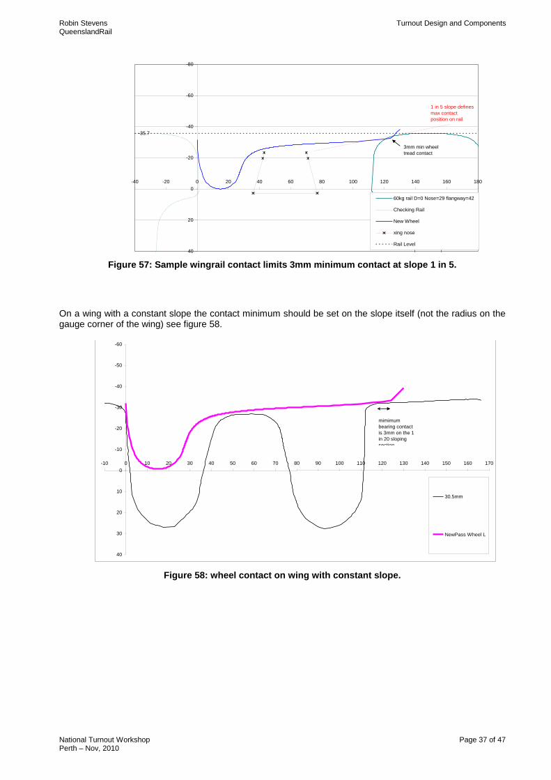
On a 60kg/m rail the edge of the rail drops away causing a mismatched contact. There should be a minimum bearing area of the wheel contacting the rail at a position where the slope on the wing rail is not excessively steep. (Refer figure 57)
Nose depth
Wing Height
16mm
Gauge Point
Bearing width nose
1
4
Robin Stevens Turnout Design and Components QueenslandRail
National Turnout Workshop Page 37 of 47 Perth – Nov, 2010
Xing Profiles 60kgm Rail Minimum Wing Contact
-35.7
-80
-60
-40
-20
0
20
40
-40 -20 0 20 40 60 80 100 120 140 160 180
60kg rail D=0 Nose=29 flangway=42
Checking Rail
New Wheel
xing nose
Rail Level
1 in 5 slope defines
max contact
position on rail
3mm min wheel
tread contact
Figure 57: Sample wingrail contact limits 3mm minimum contact at slope 1 in 5.
On a wing with a constant slope the contact minimum should be set on the slope itself (not the radius on the gauge corner of the wing) see figure 58. Prototype Monoblock Crossing Showing Wing Contact
-60
-50
-40
-30
-20
-10
0
10
20
30
40
-10 0 10 20 30 40 50 60 70 80 90 100 110 120 130 140 150 160 170
30.5mm
NewPass Wheel L
mimimum
bearing contact
is 3mm on the 1
in 20 sloping
section
Figure 58: wheel contact on wing with constant slope.
Robin Stevens Turnout Design and Components QueenslandRail
National Turnout Workshop Page 38 of 47 Perth – Nov, 2010
13.7 Impact
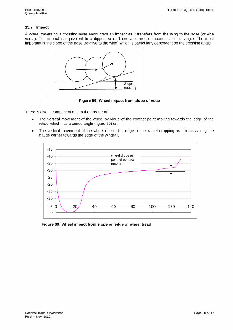
A wheel traversing a crossing nose encounters an impact as it transfers from the wing to the nose (or vice versa). The impact is equivalent to a dipped weld. There are three components to this angle. The most important is the slope of the nose (relative to the wing) which is particularly dependent on the crossing angle.
Figure 59: Wheel impact from slope of nose
There is also a component due to the greater of:
The vertical movement of the wheel by virtue of the contact point moving towards the edge of the wheel which has a coned angle (figure 60) or:
The vertical movement of the wheel due to the edge of the wheel dropping as it tracks along the gauge corner towards the edge of the wingrail.
pro rata y #DIV/0!
-45
-40
-35
-30
-25
-20
-15
-10
-5
0
0 20 40 60 80 100 120 140
wheel drops as
point of contact
moves
Figure 60: Wheel impact from slope on edge of wheel tread
Slope causing impact
Robin Stevens Turnout Design and Components QueenslandRail
National Turnout Workshop Page 39 of 47 Perth – Nov, 2010
Xing Profiles Wheel Edge
-44
-39
-34
-29
-24
-19100 120 140 160 180
w heel drops as edge
moves dow n corner of
w ing.
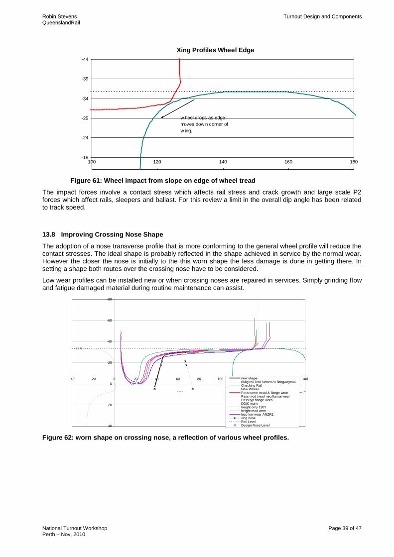
Figure 61: Wheel impact from slope on edge of wheel tread
The impact forces involve a contact stress which affects rail stress and crack growth and large scale P2 forces which affect rails, sleepers and ballast. For this review a limit in the overall dip angle has been related to track speed.
13.8 Improving Crossing Nose Shape
The adoption of a nose transverse profile that is more conforming to the general wheel profile will reduce the contact stresses. The ideal shape is probably reflected in the shape achieved in service by the normal wear. However the closer the nose is initially to the this worn shape the less damage is done in getting there. In setting a shape both routes over the crossing nose have to be considered.
Low wear profiles can be installed new or when crossing noses are repaired in services. Simply grinding flow and fatigue damaged material during routine maintenance can assist.
Xing Profiles - new crossing nose shape for 60kg/m
With contact for various wheels and 6mm offset from wing. (full shape shown but only applied to mid-point of nose)
-33.6
56, -29.2
-80
-60
-40
-20
0
20
40
-40 -20 0 20 40 60 80 100 120 140 160 180new shape60kg rail D=6 Nose=24 flangway=44Checking RailNew WheelPass some tread & flange wearPass mod tread neg flange wearPass typ flange wornDDIC wornfreight only 130?freight mod wornloco low wear ANZR1xing noseRail LevelDesign Nose Level
Figure 62: worn shape on crossing nose, a reflection of various wheel profiles.
Robin Stevens Turnout Design and Components QueenslandRail
National Turnout Workshop Page 40 of 47 Perth – Nov, 2010
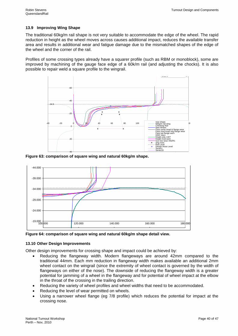
13.9 Improving Wing Shape
The traditional 60kg/m rail shape is not very suitable to accommodate the edge of the wheel. The rapid reduction in height as the wheel moves across causes additional impact, reduces the available transfer area and results in additional wear and fatigue damage due to the mismatched shapes of the edge of the wheel and the corner of the rail. Profiles of some crossing types already have a squarer profile (such as RBM or monoblock), some are improved by machining of the gauge face edge of a 60k/m rail (and adjusting the chocks). It is also possible to repair weld a square profile to the wingrail.
Xing Profiles - new modified wing
With contact for various wheels
-34.5
-80
-60
-40
-20
0
20
40
-40 -20 0 20 40 60 80 100 120 140 160 180new shape60kg/m rail wingChecking RailNew WheelPass some tread & flange wearPass mod tread neg flange wearPass typ flange wornDDIC wornfreight only 130?freight mod wornloco low wear ANZR1xing noseRail LevelDesign Nose LevelSeries1Series10
flange width 44
nose width 28
offset 0
Figure 63: comparison of square wing and natural 60kg/m shape.
Xing Profiles Wheel Edge
-44.000
-39.000
-34.000
-29.000
-24.000
-19.000100.000 120.000 140.000 160.000 180.000
Figure 64: comparison of square wing and natural 60kg/m shape detail view.
13.10 Other Design Improvements
Other design improvements for crossing shape and impact could be achieved by:
Reducing the flangeway width. Modern flangeways are around 42mm compared to the traditional 44mm. Each mm reduction in flangeway width makes available an additional 2mm wheel contact on the wingrail (since the extremity of wheel contact is governed by the width of flangeways on either of the nose). The downside of reducing the flangeway width is a greater potential for jamming of a wheel in the flangeway and for potential of wheel impact at the elbow in the throat of the crossing in the trailing direction.
Reducing the variety of wheel profiles and wheel widths that need to be accommodated.
Reducing the level of wear permitted on wheels.
Using a narrower wheel flange (eg 7/8 profile) which reduces the potential for impact at the crossing nose.

Robin Stevens Turnout Design and Components QueenslandRail
National Turnout Workshop Page 41 of 47 Perth – Nov, 2010
14. GUARDRAIL/CHECKRAIL UNIT
The guardrail/checkrail units are opposite the “V” crossing. The purpose of the guardrail/checkrails is to control the position and direction of the vehicle wheels as they pass through the flangeways of the crossing. (Refer Figure 65).
The unit consists of a length of rail (called the guardrail/checkrail) with a flared bevel machined on each end, hardened on the checking face, bolted through chocks/shims to a closure rail (called the guardrail/checkrail carrier). The centre of the checkrail should be opposite the theoretical point of the “V” crossing.
Straight guardrail/checkrails are chamfered. This means that the same size chock can be used all the way through and there is no need for shims. (Refer Figure 66).
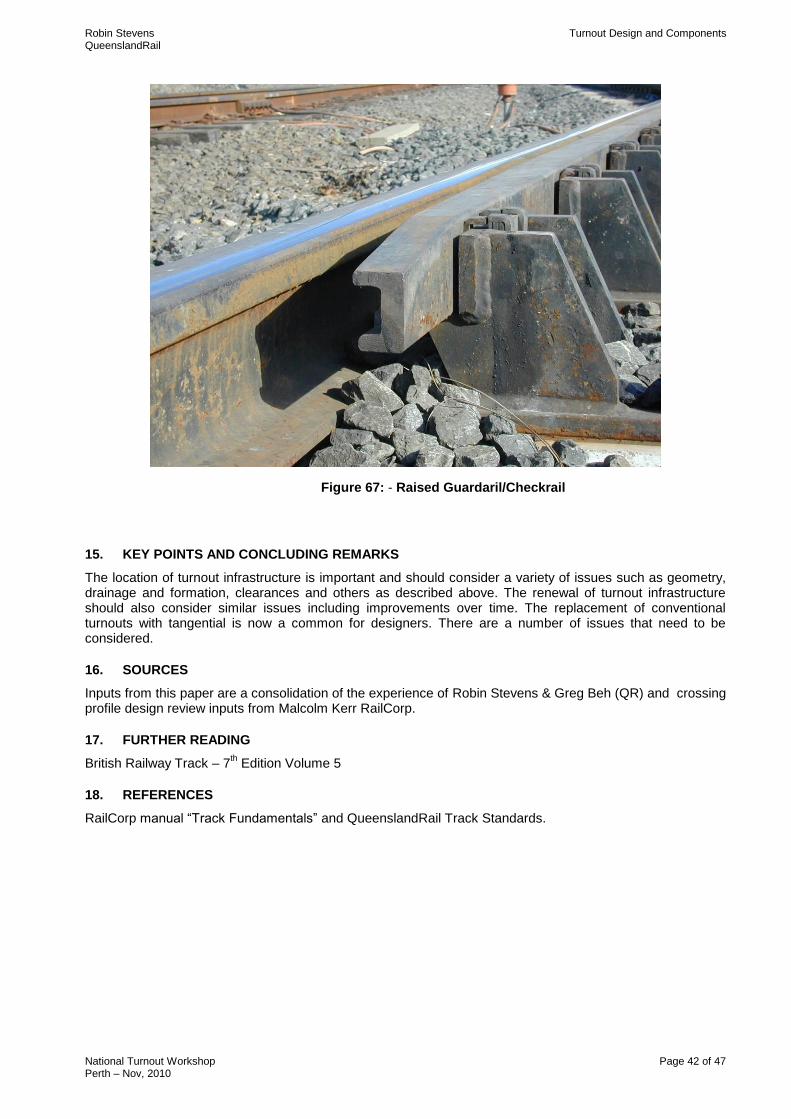
On some turnouts (eg tangentials) the guardrail/checkrail is higher than the guardrail/checkrail carrier. They are made from special guard rail section (UIC 33) and bolted to special elevated guard rail chairs. This is called a raised guardrail/checkrail. (Refer Figure 67).
The centre of the guardrail/checkrail is usually opposite the theoretical point of the crossing.
Due to the construction of “V” crossings, there is a gap between the practical point and the throat across which there is no rail to guide the wheel. When a wheel follows the outer rail of the turnout the tendency is for it to travel outwards when it reaches the gap. If this occurs, the wheel flange could travel on the wrong side of the crossing and derail. This is prevented by the guardrail/checkrail that engages the back of the opposite wheel and guides the flange onto the correct side of the crossing point.
This action takes place each time a wheel moves in a facing direction through a crossing and the whole safety of the movement depends on the checkrail. Consequently, the maintenance of the correct position and rigid fastening of the guardrail/checkrail is of particular importance.
Some guardrail/checkrail flangeways are adjusted by using spacer shims with the chocks.
Figure 65: - Guardrail/Checkrails at the “v” crossing
Figure 66: - Guardrail/Checkrail machine chamfered from straight rail
Robin Stevens Turnout Design and Components QueenslandRail
National Turnout Workshop Page 42 of 47 Perth – Nov, 2010
Figure 67: - Raised Guardaril/Checkrail
15. KEY POINTS AND CONCLUDING REMARKS
The location of turnout infrastructure is important and should consider a variety of issues such as geometry, drainage and formation, clearances and others as described above. The renewal of turnout infrastructure should also consider similar issues including improvements over time. The replacement of conventional turnouts with tangential is now a common for designers. There are a number of issues that need to be considered.
16. SOURCES
Inputs from this paper are a consolidation of the experience of Robin Stevens & Greg Beh (QR) and crossing profile design review inputs from Malcolm Kerr RailCorp.
17. FURTHER READING
British Railway Track – 7th Edition Volume 5
18. REFERENCES
RailCorp manual “Track Fundamentals” and QueenslandRail Track Standards.
Robin Stevens Turnout Design and Components QueenslandRail
National Turnout Workshop Page 43 of 47 Perth – Nov, 2010
19. APPENDIX A
Robin Stevens Turnout Design and Components QueenslandRail
National Turnout Workshop Page 44 of 47 Perth – Nov, 2010
Robin Stevens Turnout Design and Components QueenslandRail
National Turnout Workshop Page 45 of 47 Perth – Nov, 2010
Robin Stevens Turnout Design and Components QueenslandRail
National Turnout Workshop Page 46 of 47 Perth – Nov, 2010
Robin Stevens Turnout Design and Components QueenslandRail
National Turnout Workshop Page 47 of 47 Perth – Nov, 2010


