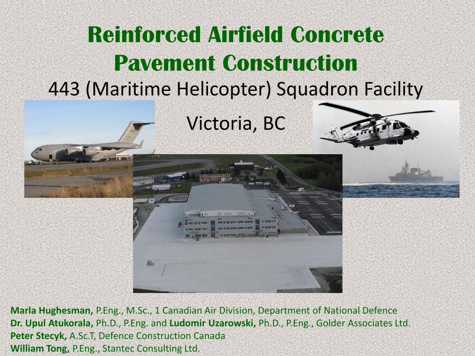
Reinforced Airfield Concrete
Pavement Construction443 (Maritime Helicopter) Squadron Facility
Victoria, BC
Marla Hughesman, P.Eng., M.Sc., 1 Canadian Air Division, Department of National DefenceDr. Upul Atukorala, Ph.D., P.Eng. and Ludomir Uzarowski, Ph.D., P.Eng., Golder Associates Ltd.Peter Stecyk, A.Sc.T, Defence Construction CanadaWilliam Tong, P.Eng., Stantec Consulting Ltd.
Acknowledgements• QA Laboratory and Field Staff - Golder Associates Ltd. Victoria, BC
• Oon Soo Ooi, P.Eng. Golder Associates Ltd. Vancouver, BC
• QC Laboratory and Field Staff - Goal Engineering Ltd. Victoria, BC
• Consulting Metro Testing Burnaby, BC
• G. Lecuyer, P.Eng. EXL Engineering Inc, Victoria, BC
• Steve Heyer & Matt Haig, Knappett Projects Inc. Victoria, BC
• Tom Raagner (PM) & John Mah, P.Eng., Jack Cewe Ltd. Coquitlam, BC
• Manuel Garcia & Doug Kumm, Proform Concrete Services Inc. Red Deer, Alberta
• Paul L. Leuschen, Alliance Paving Solutions Inc. Underwood, Iowa 51576
• Todd Hanson & Doug Saqui, Butler Brothers Supplies Ltd. Central Saanich, BC
Acknowledgements
Presentation Outline
• Introduction
• Geotechnical Design
• Structural Design
• Concrete Pavement Design Requirements
• Construction Methodology
– Problems / Solutions
• Contractor’s QC Plan
• Construction QC/QA
• Contract Design Tolerances, Final Construction Tolerances
• Lessons Learned and Conclusions
Introduction
• Location of the new 443 (Maritime helicopter) Squadron is 30 kilometers North of Victoria BC at Victoria International Airport.
• The Squadron facility is a 20,000m2 operations, maintenance and storage hanger in support of the Department of National Defence’s Pacific Helicopter Fleet.
• To the East and North of the hangar is a 25,500m2 concrete apron capable of accommodating five Sikorsky CH-148 Cyclone helicopters and a Boeing CC-177 Globemaster.
• The apron area consists of two pavement thicknesses:
– 420mm on the North side of the facility to accommodate CC-177
– 300mm on the East side to taxi the CH-128 helicopters to the hanger.
Geotechnical Design
Overall Site Grading:
• The original site grade was 3 m below the adjoining taxiway. Raising the site grade would induce long-term settlements in the underlying clays.
• Measures were implemented to accelerate the settlements in the apron area using preloading and surcharging of the subgrade
Apron Area:
• Sensitive to total and differential settlements. Apron to be constructed on weak subgrade soils.
• Robust design of the concrete apron overlying Cement Treated Base (CTB).
Geotechnical Design
• Detailed field investigations were carried out to establish subsurface conditions and variations in bedrock surface elevations.
• Investigations were conducted in phases:
– Boreholes without rock coring/mapping at 9 locations.
– Cone Penetration Tests (CPT) at 3 locations.
– Seismic refraction (geophysical) surveys along 7 lines.
Geotechnical Design
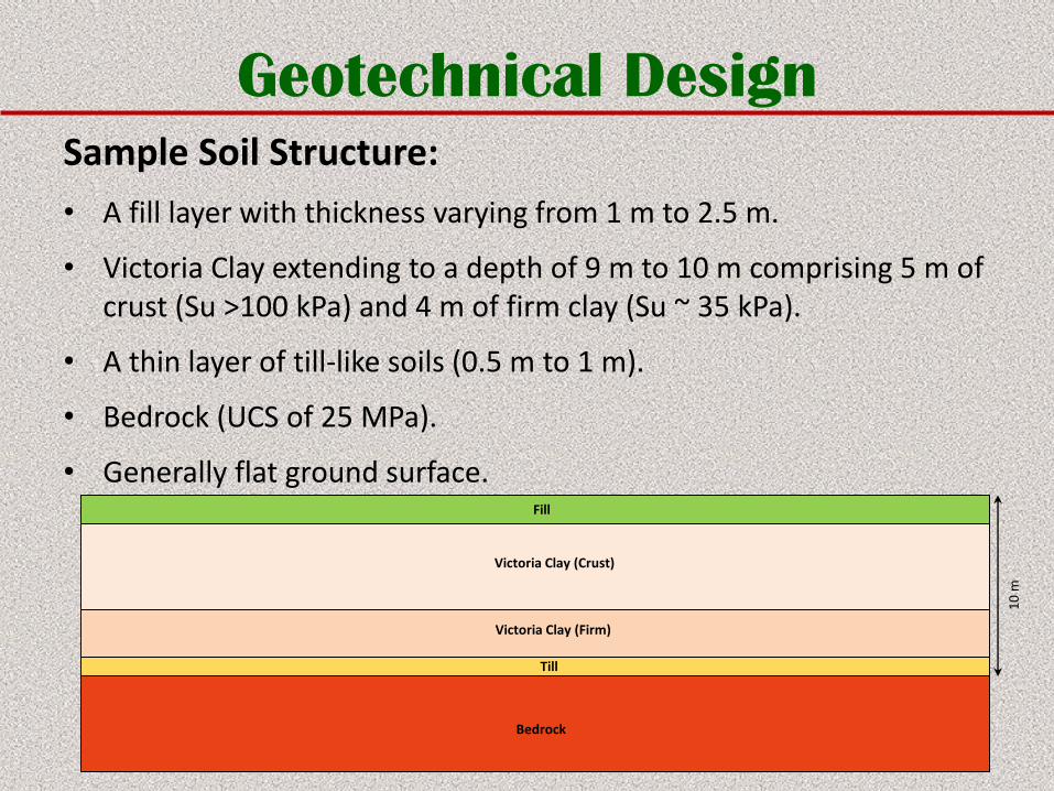
Sample Soil Structure:
• A fill layer with thickness varying from 1 m to 2.5 m.
• Victoria Clay extending to a depth of 9 m to 10 m comprising 5 m of crust (Su >100 kPa) and 4 m of firm clay (Su ~ 35 kPa).
• A thin layer of till-like soils (0.5 m to 1 m).
• Bedrock (UCS of 25 MPa).
• Generally flat ground surface.Fill
Victoria Clay (Crust)
Victoria Clay (Firm)
Till
Bedrock
10
m
Geotechnical Design
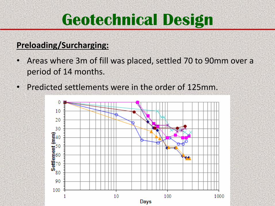
Preloading/Surcharging:
• Areas where 3m of fill was placed, settled 70 to 90mm over a period of 14 months.
• Predicted settlements were in the order of 125mm.
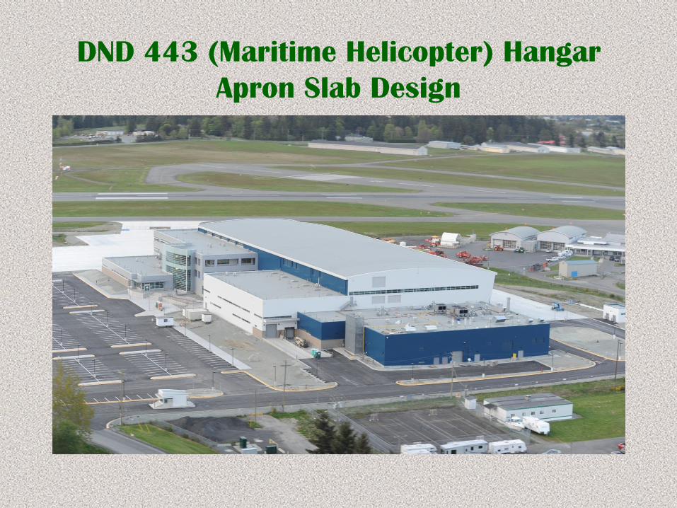
DND 443 (Maritime Helicopter) Hangar
Apron Slab Design
Structural Design
1. Apron Loading & Design Criteria
2. Analysis, Modelling & Design
3. Results & Discussion
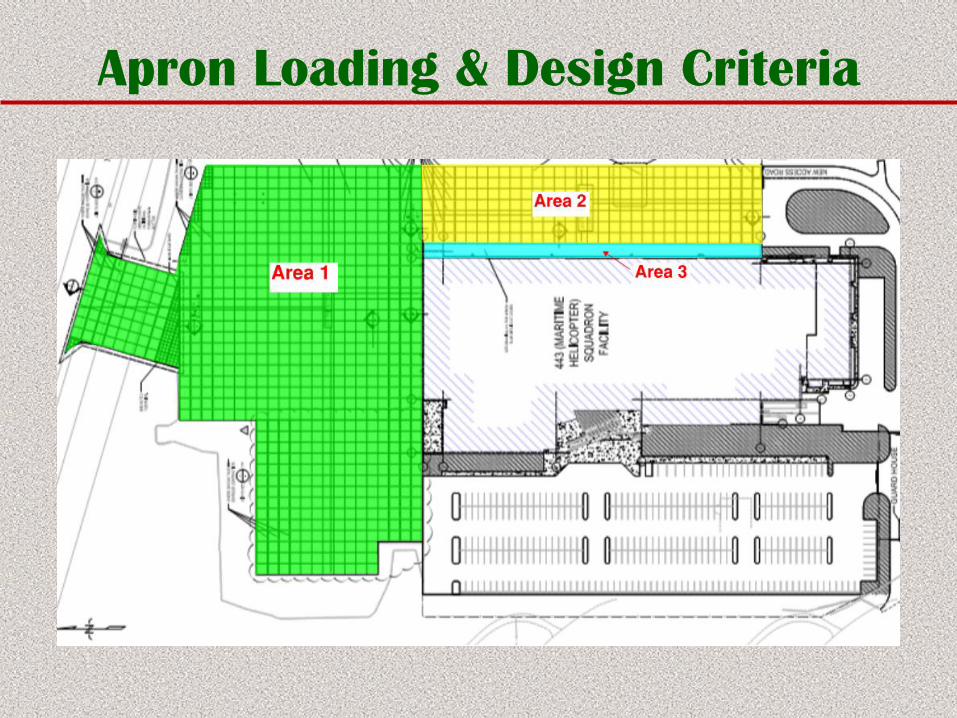
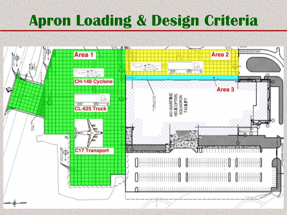
Apron Loading & Design Criteria
Three Operational Areas:
• Area 1: CC-177 Aircraft, CL625 Truck and Cyclone Helicopter
• Area 2: Cyclone Helicopter and CL625 Truck
• Area 3: Bridge Slab Between Hangar and Apron
*Robust Design for long term performance.
Apron Loading & Design Criteria
Apron Loading & Design Criteria
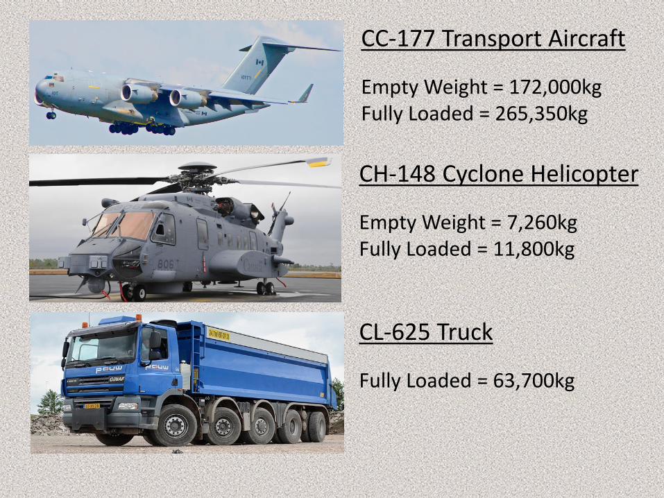
CC-177 Transport Aircraft
Empty Weight = 172,000kgFully Loaded = 265,350kg
CH-148 Cyclone Helicopter
Empty Weight = 7,260kgFully Loaded = 11,800kg
CL-625 Truck
Fully Loaded = 63,700kg
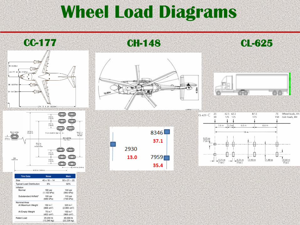
Wheel Load Diagrams
CC-177 CH-148 CL-625
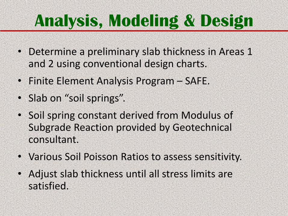
Analysis, Modeling & Design
• Determine a preliminary slab thickness in Areas 1 and 2 using conventional design charts.
• Finite Element Analysis Program – SAFE.
• Slab on “soil springs”.
• Soil spring constant derived from Modulus of Subgrade Reaction provided by Geotechnical consultant.
• Various Soil Poisson Ratios to assess sensitivity.
• Adjust slab thickness until all stress limits are satisfied.
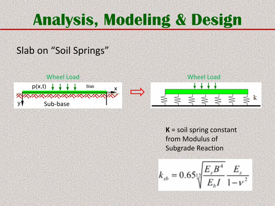
Analysis, Modeling & Design
Slab on “Soil Springs”
K = soil spring constant from Modulus of Subgrade Reaction
Wheel LoadWheel Load
Sub-base
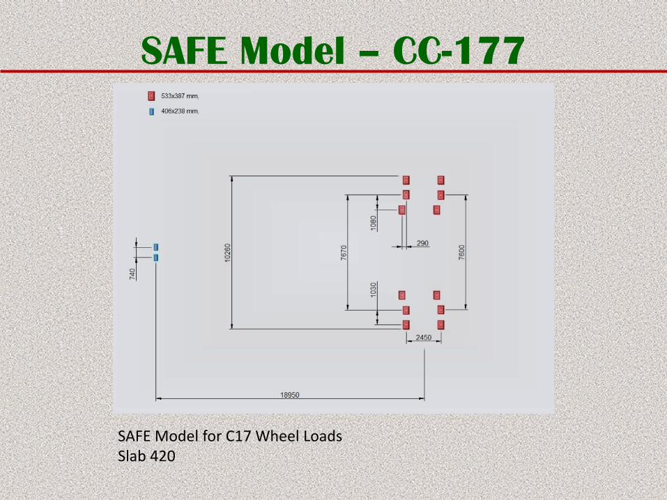
SAFE Model – CC-177
SAFE Model for C17 Wheel LoadsSlab 420
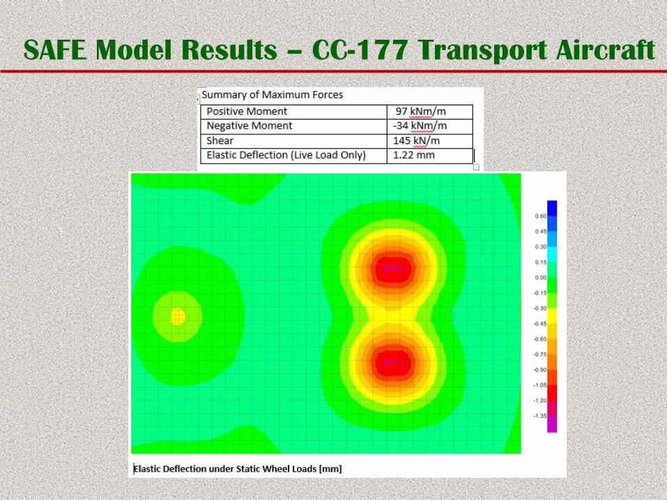
SAFE Model Results – CC-177 Transport Aircraft
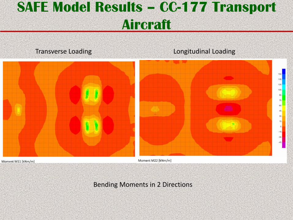
SAFE Model Results – CC-177 Transport
Aircraft
Bending Moments in 2 Directions
Transverse Loading Longitudinal Loading
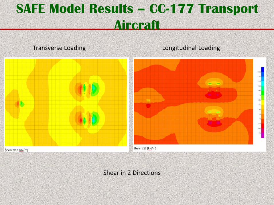
SAFE Model Results – CC-177 Transport
Aircraft
Shear in 2 Directions
Transverse Loading Longitudinal Loading
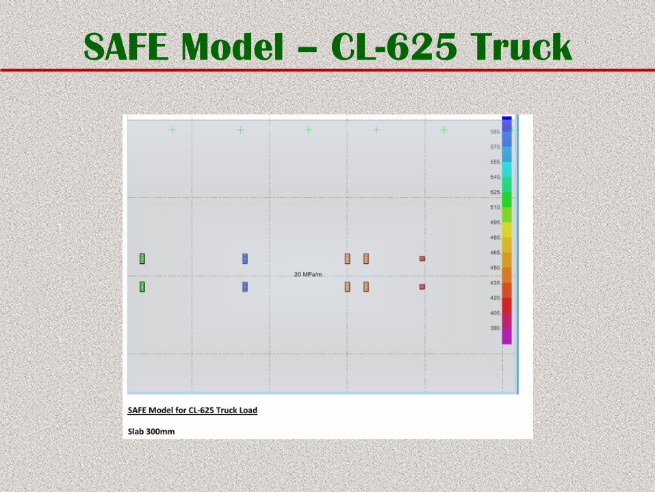
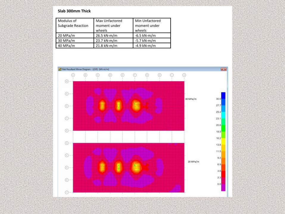
SAFE Model – CL-625 Truck
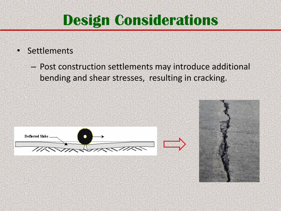
Design Considerations
• Settlements
– Post construction settlements may introduce additional bending and shear stresses, resulting in cracking.
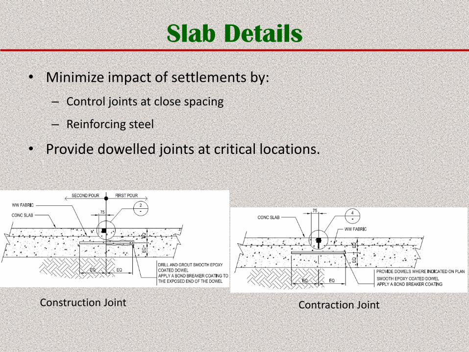
Slab Details
• Minimize impact of settlements by:
– Control joints at close spacing
– Reinforcing steel
• Provide dowelled joints at critical locations.
Construction Joint Contraction Joint
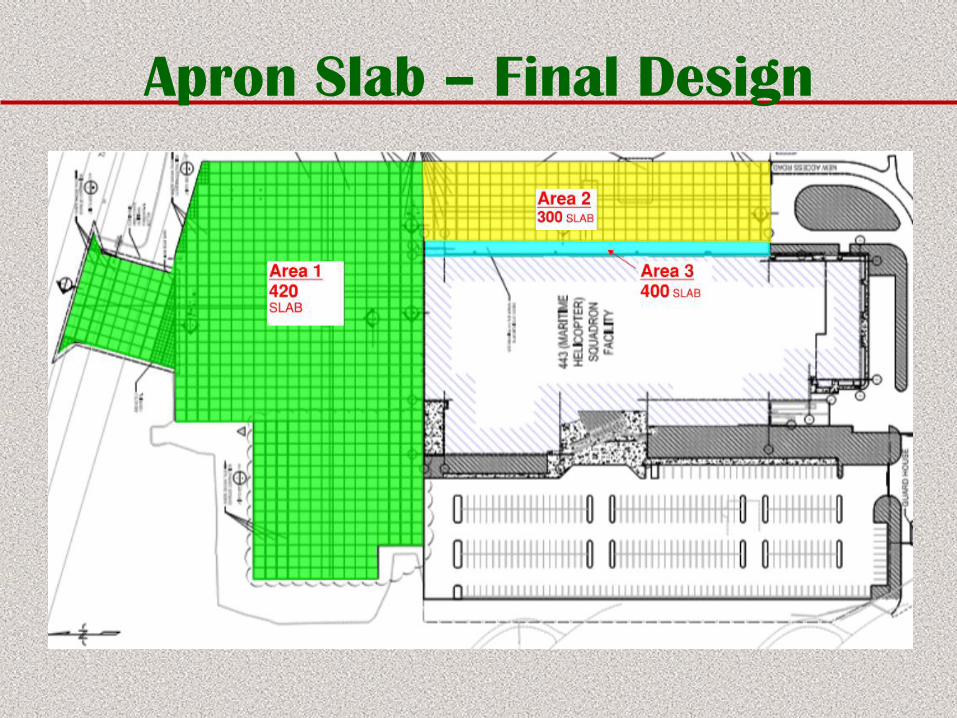
Apron Slab – Final Design
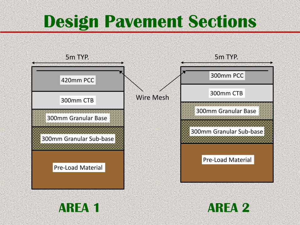
Design Pavement Sections
420mm PCC
300mm CTB
300mm Granular Base
300mm Granular Sub-base
Pre-Load Material
AREA 1
5m TYP.
300mm PCC
300mm CTB
300mm Granular Base
300mm Granular Sub-base
Pre-Load Material
AREA 2
5m TYP.
Wire Mesh
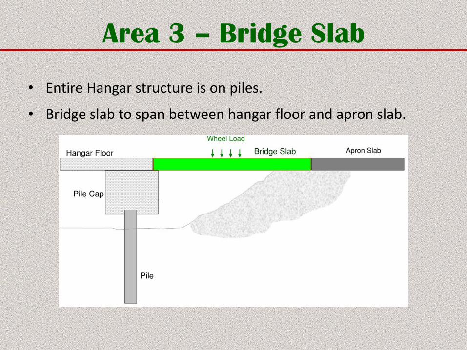
Area 3 – Bridge Slab
• Entire Hangar structure is on piles.
• Bridge slab to span between hangar floor and apron slab.
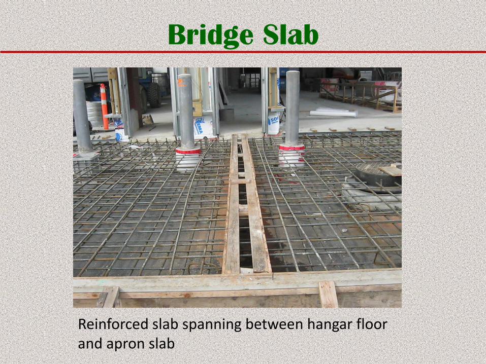
Bridge Slab
Reinforced slab spanning between hangar floor and apron slab
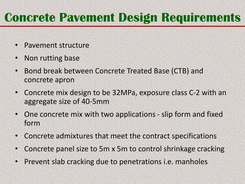
Concrete Pavement Design Requirements
• Pavement structure
• Non rutting base
• Bond break between Concrete Treated Base (CTB) and concrete apron
• Concrete mix design to be 32MPa, exposure class C-2 with an aggregate size of 40-5mm
• One concrete mix with two applications - slip form and fixed form
• Concrete admixtures that meet the contract specifications
• Concrete panel size to 5m x 5m to control shrinkage cracking
• Prevent slab cracking due to penetrations i.e. manholes
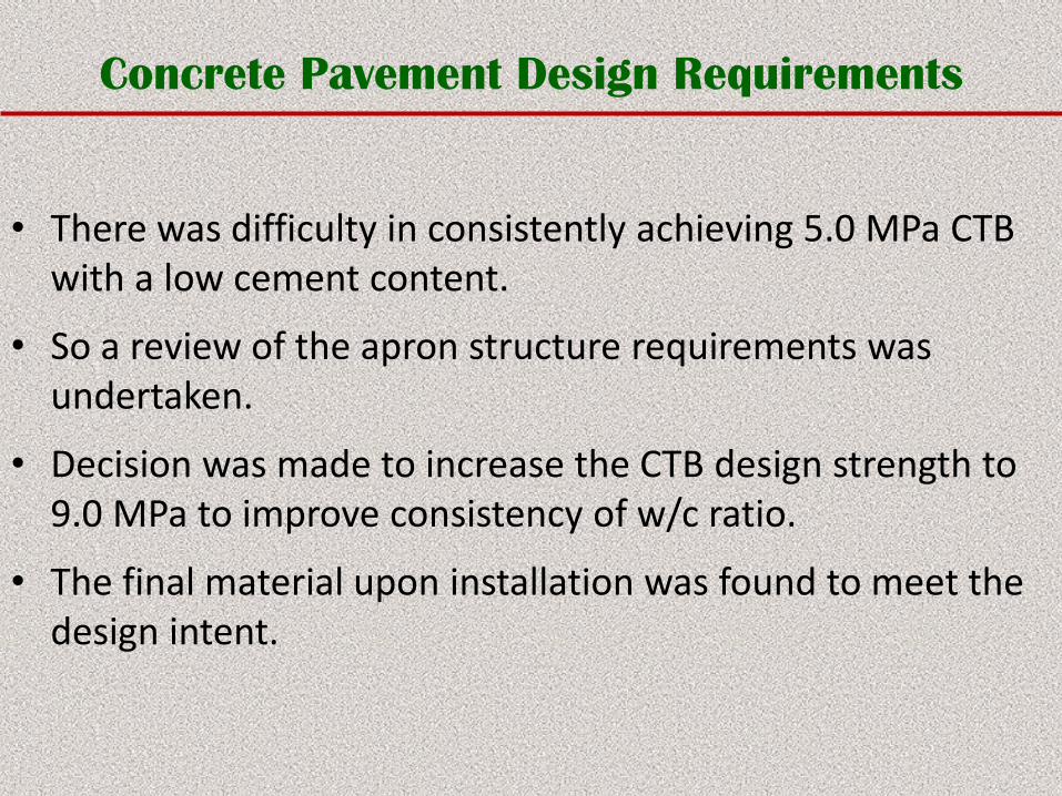
Concrete Pavement Design Requirements
• There was difficulty in consistently achieving 5.0 MPa CTB with a low cement content.
• So a review of the apron structure requirements was undertaken.
• Decision was made to increase the CTB design strength to 9.0 MPa to improve consistency of w/c ratio.
• The final material upon installation was found to meet the design intent.
Concrete Pavement Design Requirements
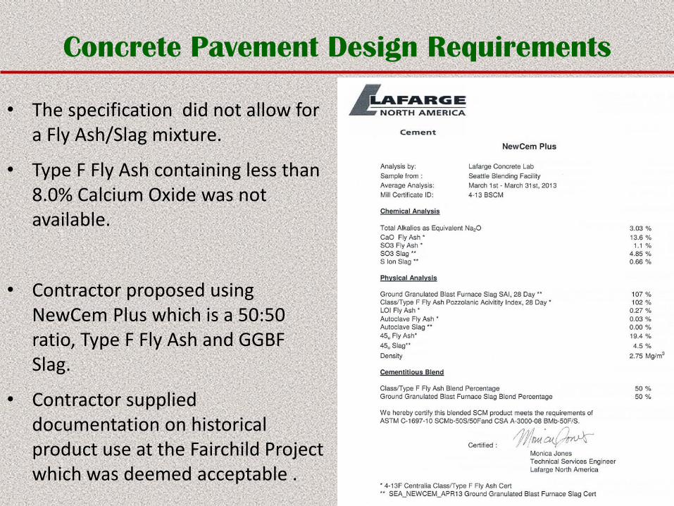
• The specification did not allow for a Fly Ash/Slag mixture.
• Type F Fly Ash containing less than 8.0% Calcium Oxide was not available.
• Contractor proposed using NewCem Plus which is a 50:50 ratio, Type F Fly Ash and GGBF Slag.
• Contractor supplied documentation on historical product use at the Fairchild Project which was deemed acceptable .
Concrete Pavement Design Requirements
• Size of nominal aggregate as per the specification should meet CAN/CSAOS23.2-2A Table 11, Group 1, Size 40-5.
• Contractor wanted to use 20-5 which concern was expressed that the larger aggregate may cause placing issues.
• Contractor placed a slip form test strip at their yard in Red Deer Alberta to prove the constructability using the reduced aggregate size.
• Based on performance of the test strip, the aggregate size 20-5 mm was approved with a 50% 19mm crush.
Concrete Pavement Design Requirements
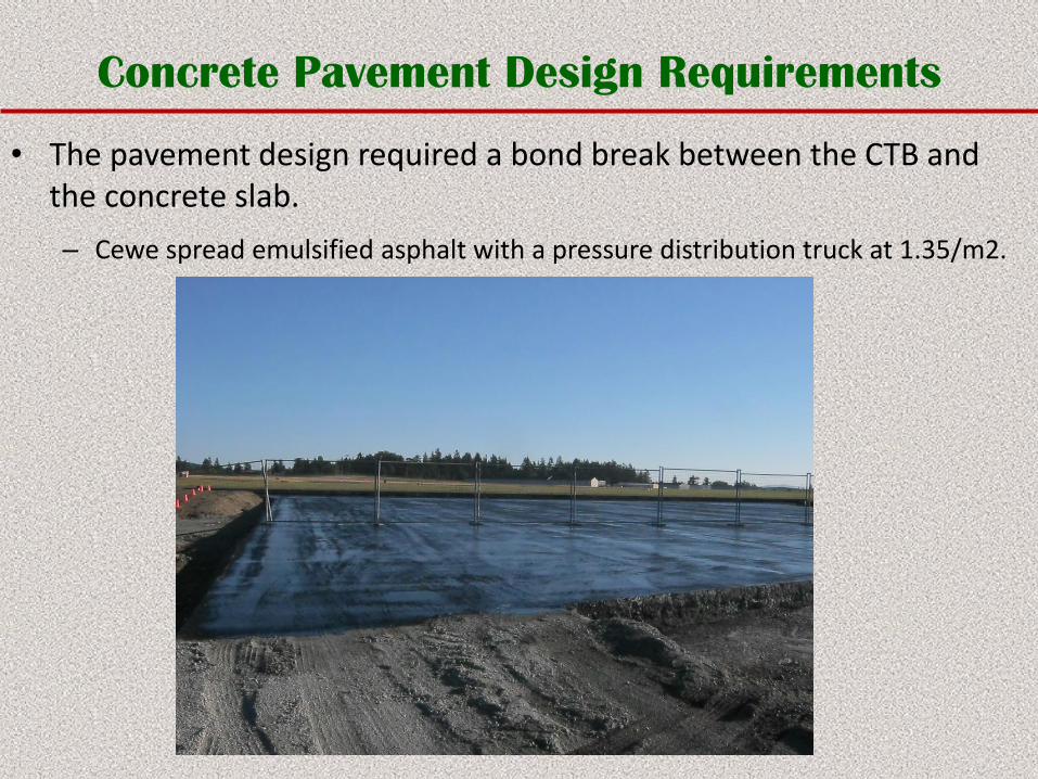
• The pavement design required a bond break between the CTB and the concrete slab.
– Cewe spread emulsified asphalt with a pressure distribution truck at 1.35/m2.
Concrete Pavement Design Requirements
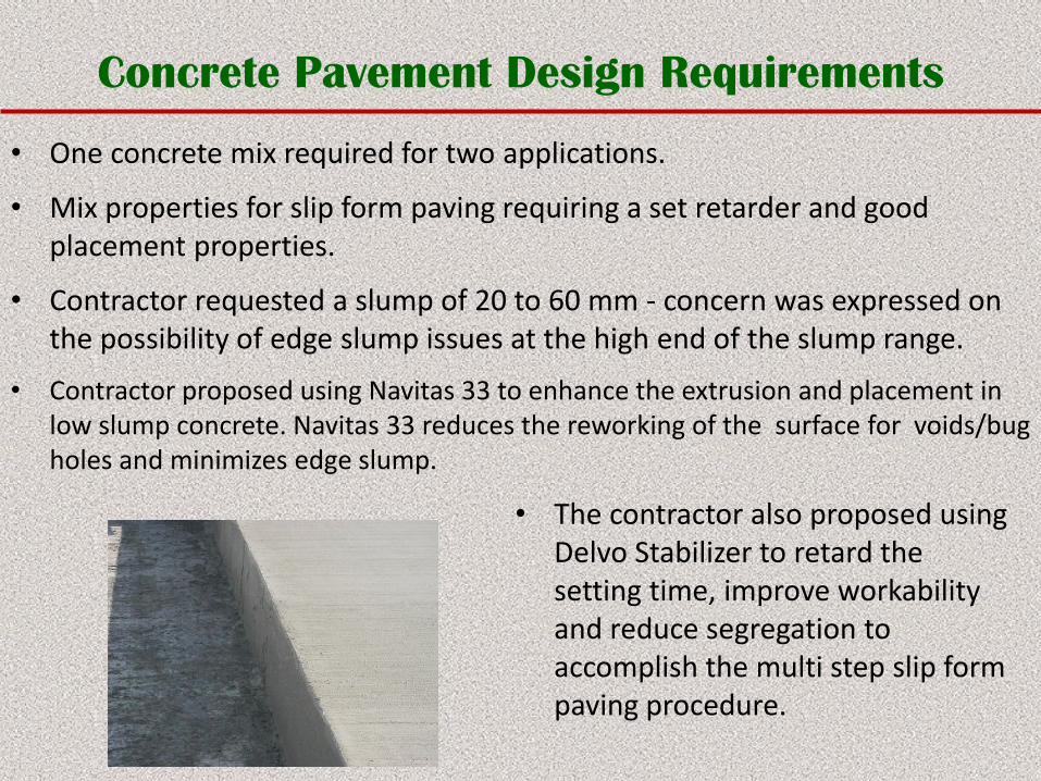
• One concrete mix required for two applications.
• Mix properties for slip form paving requiring a set retarder and good placement properties.
• Contractor requested a slump of 20 to 60 mm - concern was expressed on the possibility of edge slump issues at the high end of the slump range.
• Contractor proposed using Navitas 33 to enhance the extrusion and placement in low slump concrete. Navitas 33 reduces the reworking of the surface for voids/bug holes and minimizes edge slump.
• The contractor also proposed using Delvo Stabilizer to retard the setting time, improve workability and reduce segregation to accomplish the multi step slip form paving procedure.
Concrete Pavement Design Requirements
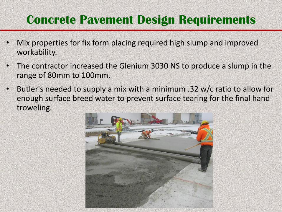
• Mix properties for fix form placing required high slump and improved workability.
• The contractor increased the Glenium 3030 NS to produce a slump in the range of 80mm to 100mm.
• Butler's needed to supply a mix with a minimum .32 w/c ratio to allow for enough surface breed water to prevent surface tearing for the final hand troweling.
Construction Methodology
• Granular subbase preparation.
• Stabilized base to improve concrete placement tolerances.
– Placement of 300mm of CTB to be compacted to 98% Modified Proctor Density.
– CTB design strength to be consistently 9 MPa.
• The Concrete Slab is required to have reinforcing mesh 75mm below the surface.
• The Concrete Slab is placed over the CTB,
– 420mm on the North side of the facility
– 300mm on the East side facility.
• Concrete Slab placement methodology - Slip Form & Fixed Form.
Construction Methodology - Sub-base Preparation
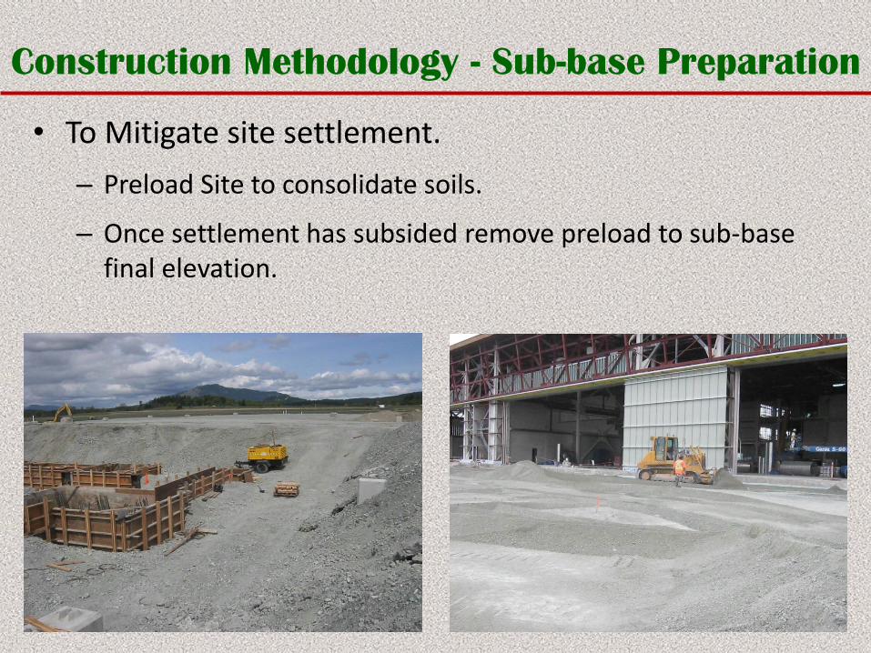
• To Mitigate site settlement.
– Preload Site to consolidate soils.
– Once settlement has subsided remove preload to sub-base final elevation.
Construction Methodology - Base Preparation
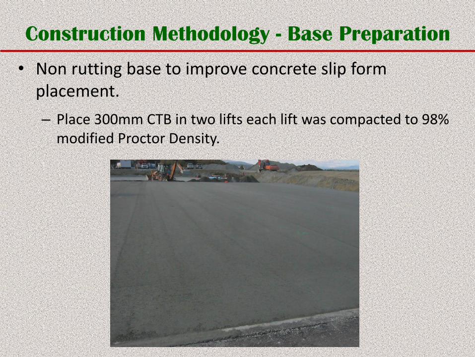
• Non rutting base to improve concrete slip form placement.
– Place 300mm CTB in two lifts each lift was compacted to 98% modified Proctor Density.
Construction Methodology - Base Preparation
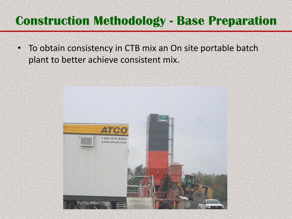
• To obtain consistency in CTB mix an On site portable batch plant to better achieve consistent mix.
Construction Methodology - Base Preparation
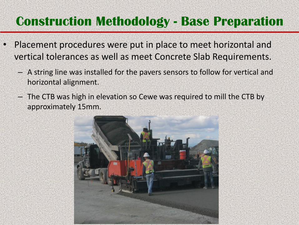
• Placement procedures were put in place to meet horizontal and vertical tolerances as well as meet Concrete Slab Requirements.
– A string line was installed for the pavers sensors to follow for vertical and horizontal alignment.
– The CTB was high in elevation so Cewe was required to mill the CTB by approximately 15mm.
Construction Methodology - Base Preparation
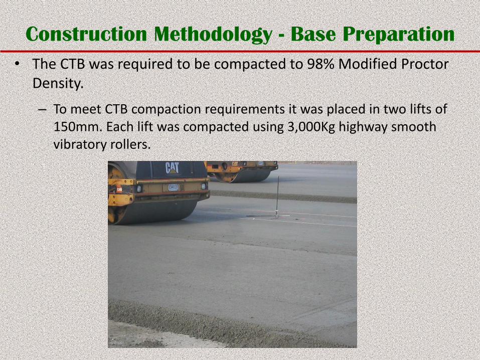
• The CTB was required to be compacted to 98% Modified Proctor Density.
– To meet CTB compaction requirements it was placed in two lifts of 150mm. Each lift was compacted using 3,000Kg highway smooth vibratory rollers.
Construction Methodology - Concrete Apron
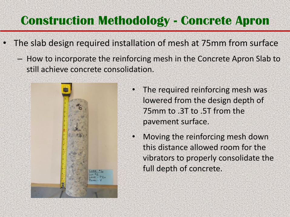
• The slab design required installation of mesh at 75mm from surface
– How to incorporate the reinforcing mesh in the Concrete Apron Slab to still achieve concrete consolidation.
• The required reinforcing mesh was lowered from the design depth of 75mm to .3T to .5T from the pavement surface.
• Moving the reinforcing mesh down this distance allowed room for the vibrators to properly consolidate the full depth of concrete.
Construction Methodology - Concrete Apron
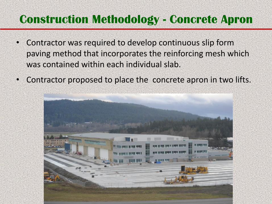
• Contractor was required to develop continuous slip form paving method that incorporates the reinforcing mesh which was contained within each individual slab.
• Contractor proposed to place the concrete apron in two lifts.
Construction Methodology - Concrete Apron
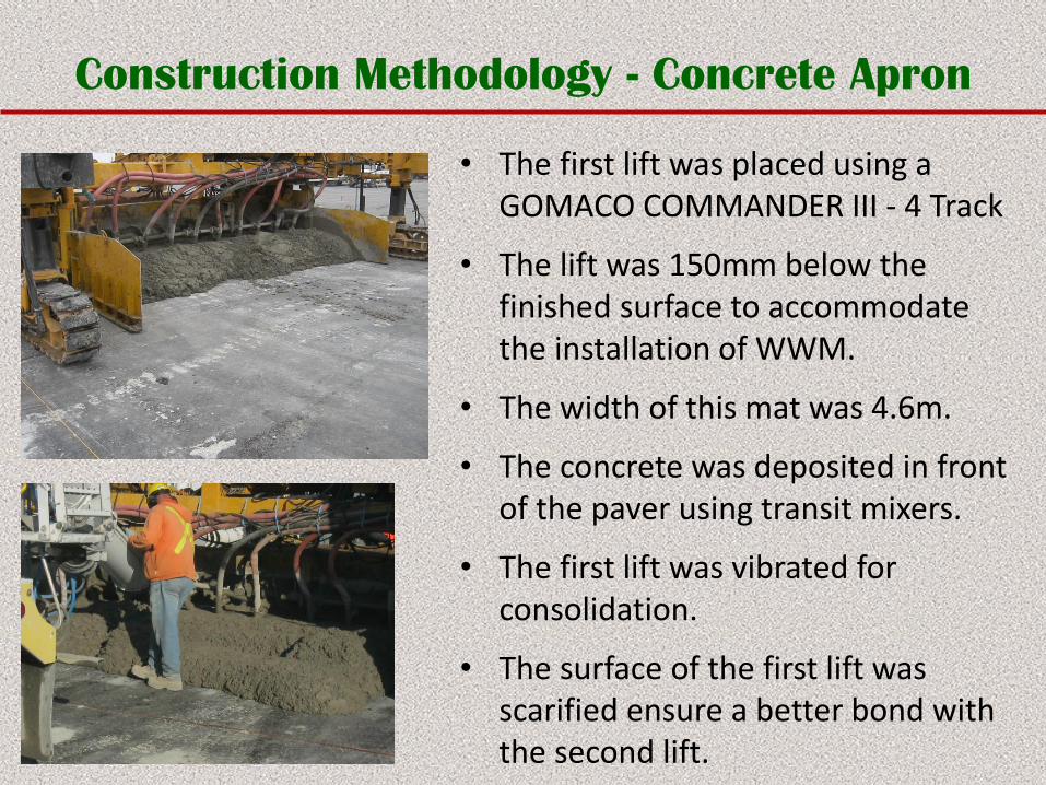
• The first lift was placed using a GOMACO COMMANDER III - 4 Track
• The lift was 150mm below the finished surface to accommodate the installation of WWM.
• The width of this mat was 4.6m.
• The concrete was deposited in front of the paver using transit mixers.
• The first lift was vibrated for consolidation.
• The surface of the first lift was scarified ensure a better bond with the second lift.
Construction Methodology - Concrete Apron
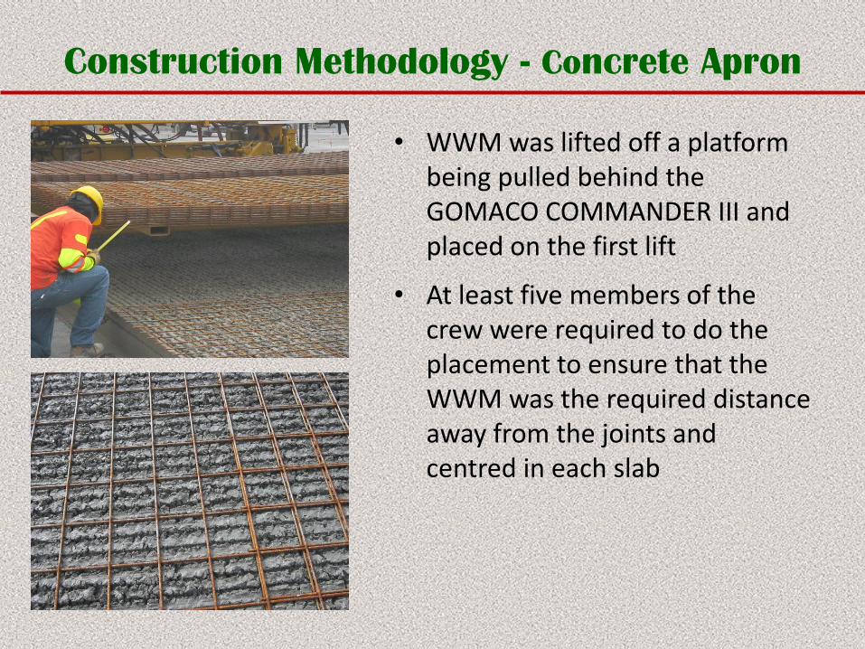
• WWM was lifted off a platform being pulled behind the GOMACO COMMANDER III and placed on the first lift
• At least five members of the crew were required to do the placement to ensure that the WWM was the required distance away from the joints and centred in each slab
Construction Methodology - Concrete Apron
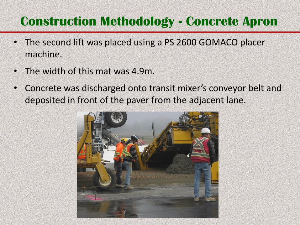
• The second lift was placed using a PS 2600 GOMACO placer machine.
• The width of this mat was 4.9m.
• Concrete was discharged onto transit mixer’s conveyor belt and deposited in front of the paver from the adjacent lane.
Construction Methodology – Concrete Apron
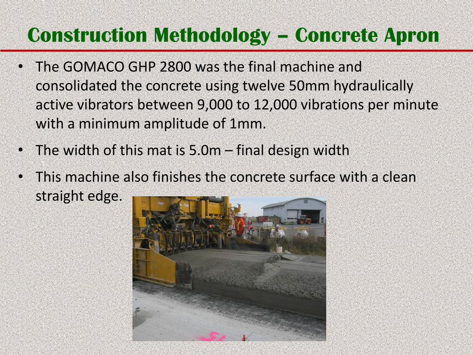
• The GOMACO GHP 2800 was the final machine and consolidated the concrete using twelve 50mm hydraulically active vibrators between 9,000 to 12,000 vibrations per minute with a minimum amplitude of 1mm.
• The width of this mat is 5.0m – final design width
• This machine also finishes the concrete surface with a clean straight edge.
Construction Methodology – Concrete Apron
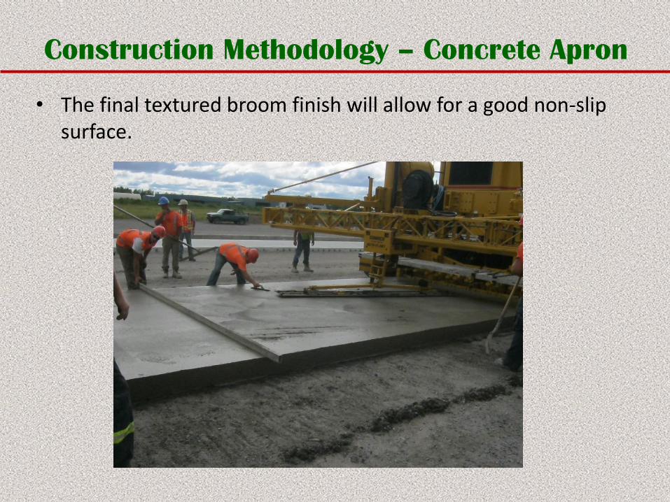
• The final textured broom finish will allow for a good non-slip surface.
Construction Methodology – Concrete Apron
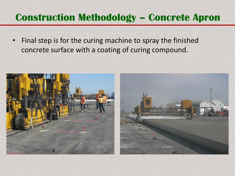
• Final step is for the curing machine to spray the finished concrete surface with a coating of curing compound.
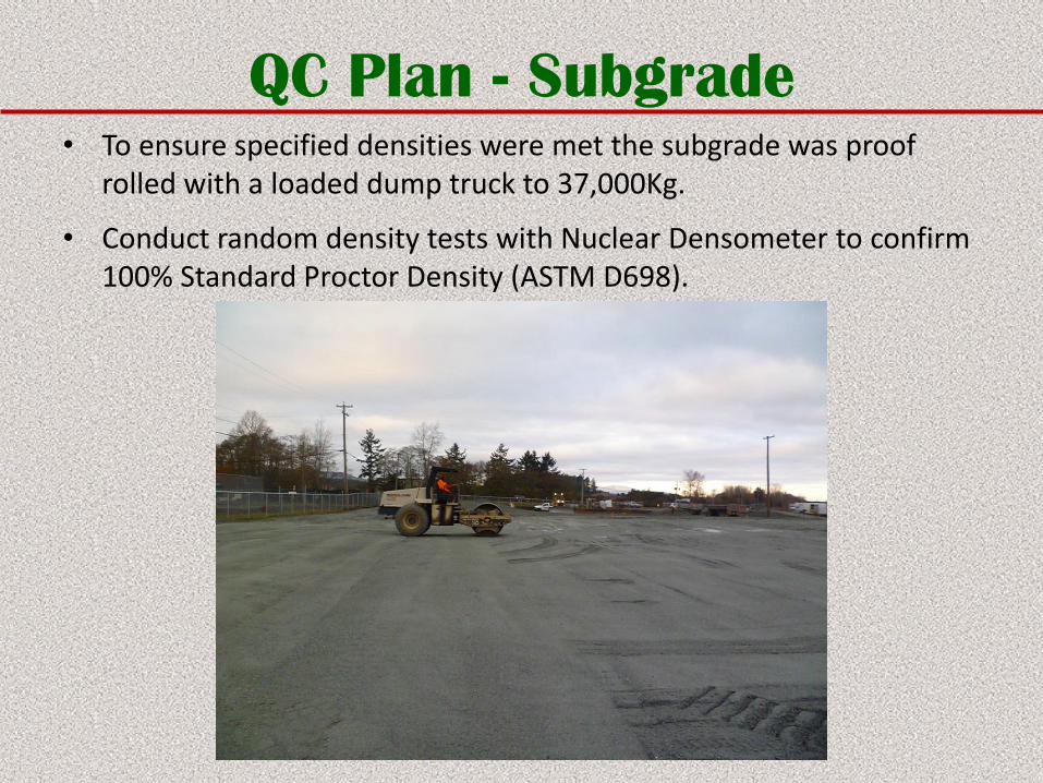
QC Plan - Subgrade• To ensure specified densities were met the subgrade was proof
rolled with a loaded dump truck to 37,000Kg.
• Conduct random density tests with Nuclear Densometer to confirm 100% Standard Proctor Density (ASTM D698).
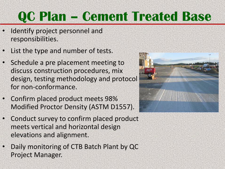
QC Plan – Cement Treated Base• Identify project personnel and
responsibilities.
• List the type and number of tests.
• Schedule a pre placement meeting to discuss construction procedures, mix design, testing methodology and protocol for non-conformance.
• Confirm placed product meets 98% Modified Proctor Density (ASTM D1557).
• Conduct survey to confirm placed product meets vertical and horizontal design elevations and alignment.
• Daily monitoring of CTB Batch Plant by QC Project Manager.
QC Plan – Concrete Apron• Schedule pre placement meeting with all parties to go over placement
methodology and discuss any concerns.
• Confirm that the final mix design has proper approval.
• Supply a plan identifying the lots, placing sequence and location of proposed test strip.
• Conduct a survey to confirm that base design grades meet elevation requirements.
• Identify the independent testing company to conduct concrete testing. Supply daily concrete summary sheets.
• Prepare and issue daily QC sheets identifying summary record of delivery, placement, joint cutting time, flatness, edge slump and thickness meets the specification.
• Confirm timing for drilling for the dowels.
• Timing of routing and joint sealing.
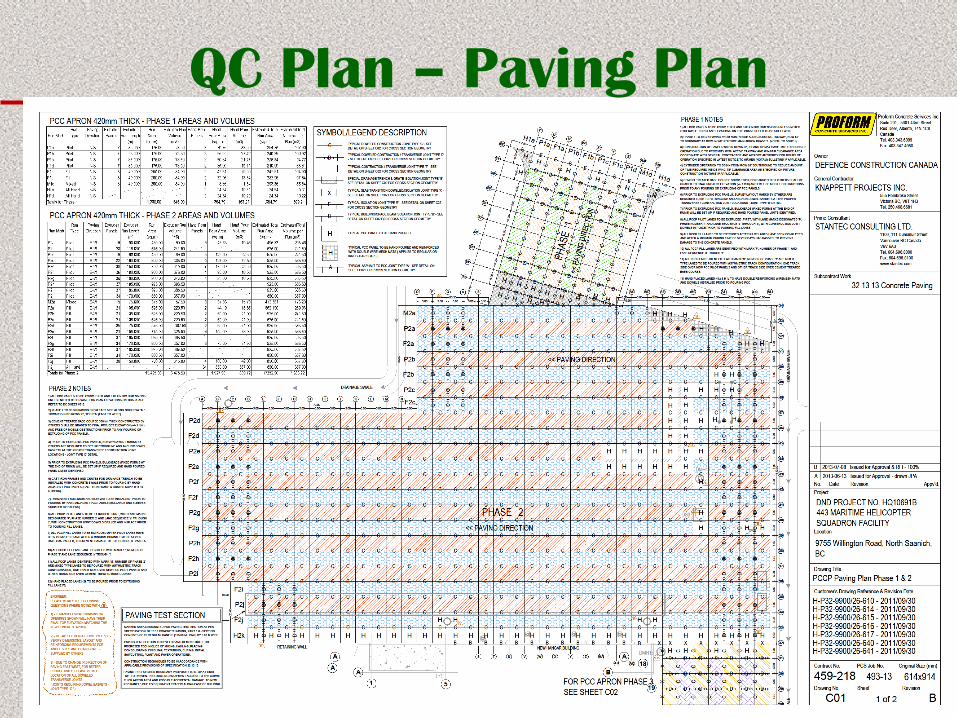
QC Plan – Paving Plan
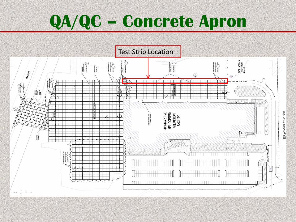
QA/QC – Concrete Apron
Test Strip Location
QA/QC – Concrete Apron
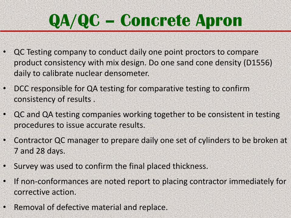
• QC Testing company to conduct daily one point proctors to compare product consistency with mix design. Do one sand cone density (D1556) daily to calibrate nuclear densometer.
• DCC responsible for QA testing for comparative testing to confirm consistency of results .
• QC and QA testing companies working together to be consistent in testing procedures to issue accurate results.
• Contractor QC manager to prepare daily one set of cylinders to be broken at 7 and 28 days.
• Survey was used to confirm the final placed thickness.
• If non-conformances are noted report to placing contractor immediately for corrective action.
• Removal of defective material and replace.
QA/QC – Concrete Apron
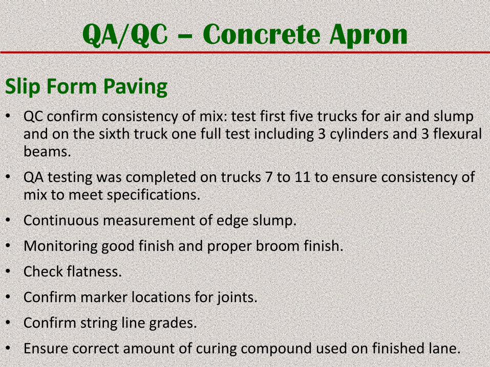
Slip Form Paving• QC confirm consistency of mix: test first five trucks for air and slump
and on the sixth truck one full test including 3 cylinders and 3 flexural beams.
• QA testing was completed on trucks 7 to 11 to ensure consistency of mix to meet specifications.
• Continuous measurement of edge slump.
• Monitoring good finish and proper broom finish.
• Check flatness.
• Confirm marker locations for joints.
• Confirm string line grades.
• Ensure correct amount of curing compound used on finished lane.
QA/QC – Concrete Apron
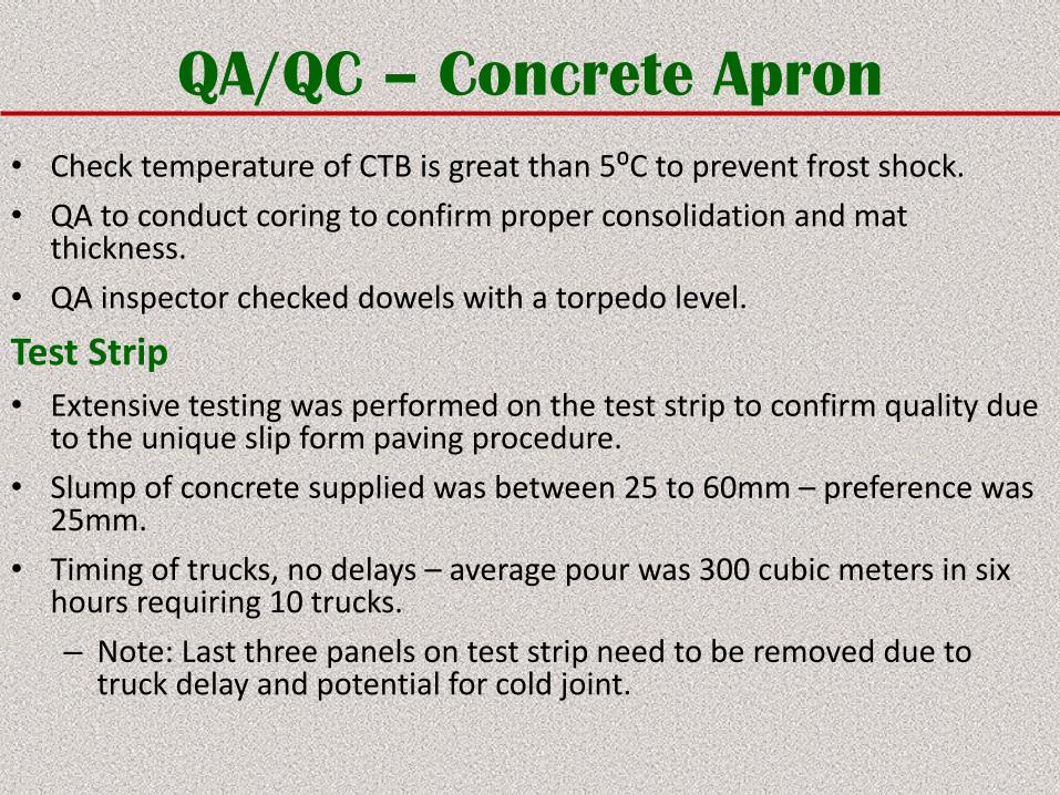
• Check temperature of CTB is great than 5⁰C to prevent frost shock.
• QA to conduct coring to confirm proper consolidation and mat thickness.
• QA inspector checked dowels with a torpedo level.
Test Strip• Extensive testing was performed on the test strip to confirm quality due
to the unique slip form paving procedure.
• Slump of concrete supplied was between 25 to 60mm – preference was 25mm.
• Timing of trucks, no delays – average pour was 300 cubic meters in six hours requiring 10 trucks.
– Note: Last three panels on test strip need to be removed due to truck delay and potential for cold joint.
QA/QC – Concrete Apron
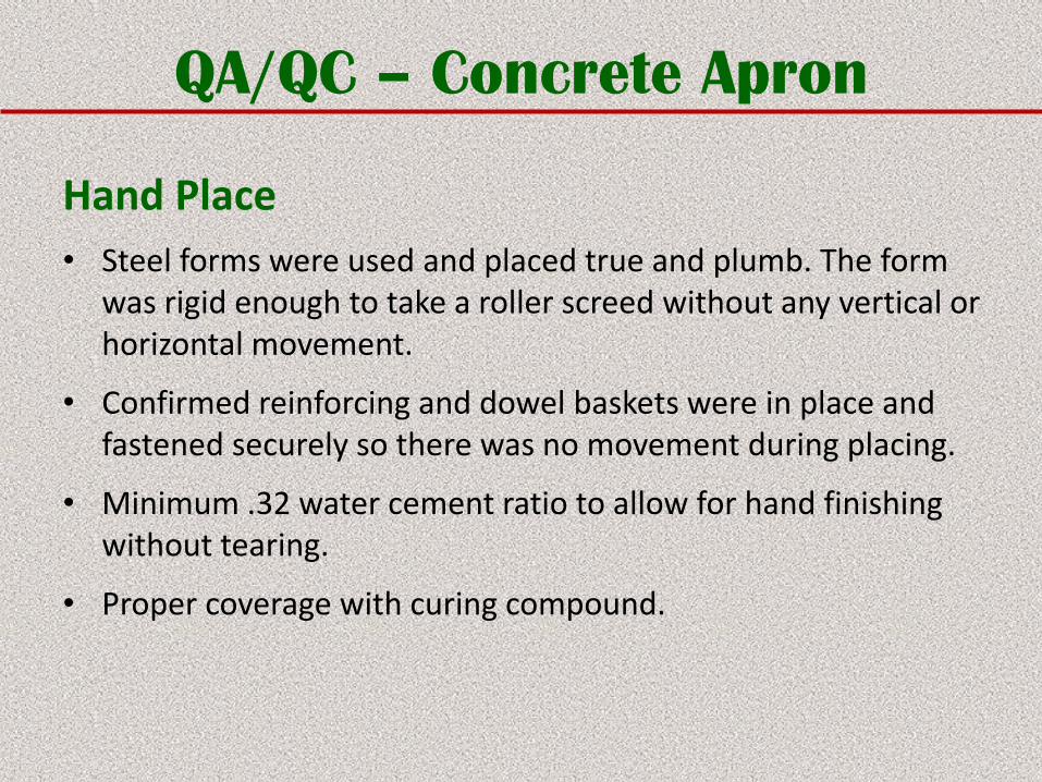
Hand Place
• Steel forms were used and placed true and plumb. The form was rigid enough to take a roller screed without any vertical or horizontal movement.
• Confirmed reinforcing and dowel baskets were in place and fastened securely so there was no movement during placing.
• Minimum .32 water cement ratio to allow for hand finishing without tearing.
• Proper coverage with curing compound.
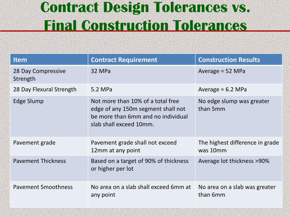
Contract Design Tolerances vs.
Final Construction Tolerances
Item Contract Requirement Construction Results
28 Day Compressive Strength
32 MPa Average = 52 MPa
28 Day Flexural Strength 5.2 MPa Average = 6.2 MPa
Edge Slump Not more than 10% of a total free edge of any 150m segment shall not be more than 6mm and no individual slab shall exceed 10mm.
No edge slump was greater than 5mm
Pavement grade Pavement grade shall not exceed 12mm at any point
The highest difference in grade was 10mm
Pavement Thickness Based on a target of 90% of thickness or higher per lot
Average lot thickness >90%
Pavement Smoothness No area on a slab shall exceed 6mm at any point
No area on a slab was greater than 6mm
Conclusion
Project succeeded due to:
– Understanding the design requirements.
– Utilizing a combination of expertise.
– Accepting new/different ideas.
– Correcting potential problems quickly.
– Working as a team to meet project objectives.
Thank you!
Questions?


