Microscope Components:
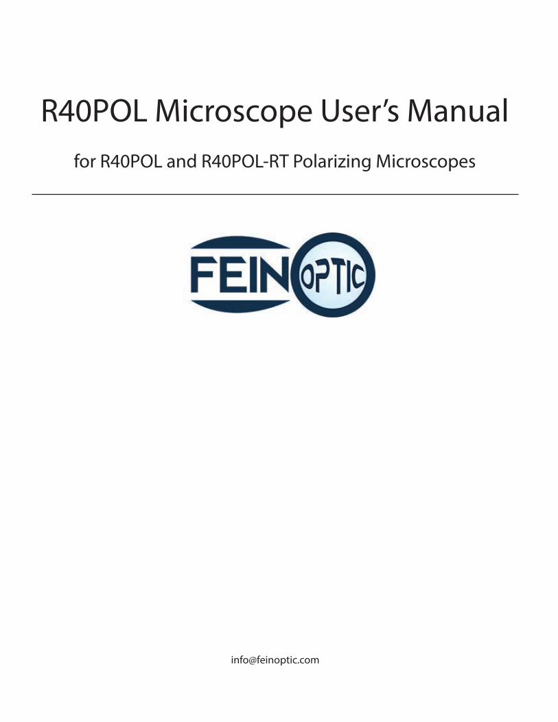
R40POL-RT Re�ected & Transmitted Light PolarizingMicroscope
Trinocular Port
Beam SplitterEyepieces
Analyzer
Polarizer Field DiaphragmAdjustment
Daylight Balancing Filter
12v 50w HalogenRe�ected Illuminator
Hex Wrench
Fine Focus
Coarse Focus
Focus Tension Adjustment
Field DiaphragmAdjustment Ring
Rotatable Stage
Switch from Re�ectedto Transmitted Illumination
ApertureDiaphragmAdjustment
GroundGlassFilter
Stage LockScrew
CondenserLock Screw
CondenserCentering Screws
BertrandLens Adjustment
12v 50w HalogenTransmitted Light
Microscope Components:
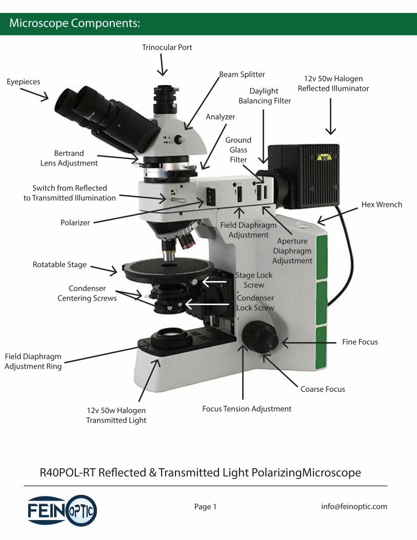
R40POL Transmitted Light Polarizing Microscope
Bertrand LensCentering Screw
CompensatingPlate
Rotatable Stage
Condenser with Polarizer
Field Diaphragm
Coarse FocusLimit Knob
Light Rheostat
FineFocus
Coarse FocusObjective
Nosepiece
Microscope Components:
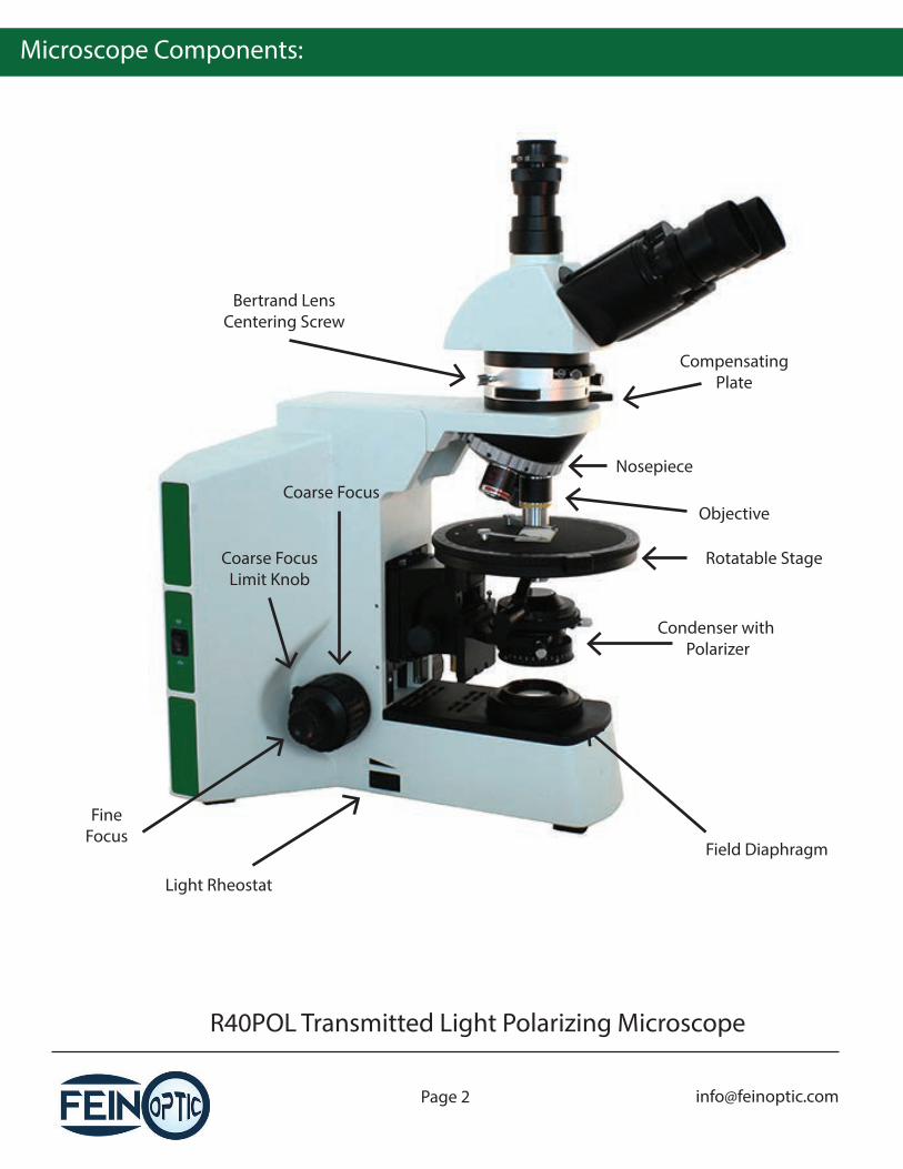
CenterableAnalyzer
Bertrand LensCentering Screw
Bertrand LensAdjustment
CompensatingPlate
Condenser HeightAdjustment Knob
CondenserCentering Screws
CompensatingPlate Filter Slot
Bertrand LensAdjustment
Lever to Switch fromRe�ected to Transmitted Light
CenterableAnalyzer
Polarizer
Before Use:
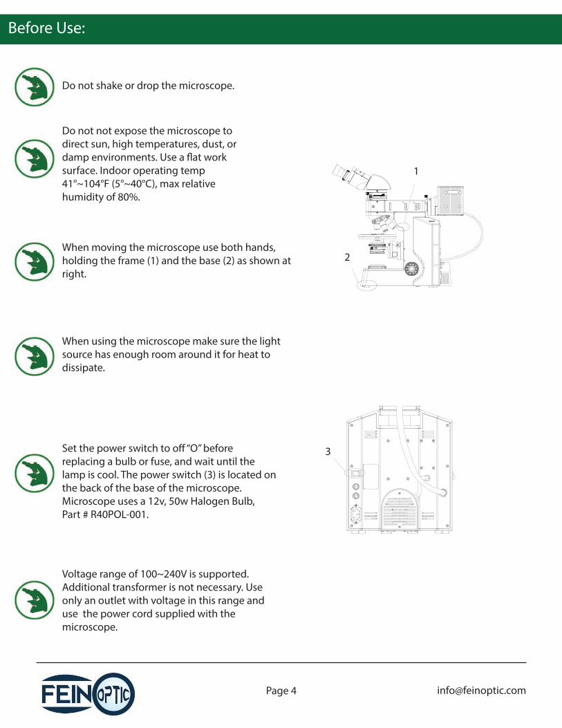
When moving the microscope use both hands, holding the frame (1) and the base (2) as shown at right.
Do not shake or drop the microscope.
Do not not expose the microscope to direct sun, high temperatures, dust, or damp environments. Use a �at work surface. Indoor operating temp 41°~104°F (5°~40°C), max relative humidity of 80%.
Set the power switch to o� “O” before replacing a bulb or fuse, and wait until the lamp is cool. The power switch (3) is located on the back of the base of the microscope. Microscope uses a 12v, 50w Halogen Bulb,Part # R40POL-001.
Voltage range of 100~240V is supported. Additional transformer is not necessary. Use only an outlet with voltage in this range and use the power cord supplied with the microscope.
1
2
3
When using the microscope make sure the light source has enough room around it for heat to dissipate.
Maintenance:
If the microscope becomes wet during use, power off the microscope and dry the microscope thoroughly.
Wipe lenses gently with a soft tissue. Carefully remove excess oil from the 100x immersion oil lens. Wipe o� �ngerprints from lens surfaces with lens paper using a small amount of microscope cleaning solution or a 3:7 mixture of alcohol and ether or dimethylbenzene. (Alcohol and ether are �ammable, do not place these chemicals near �re and clean in a ventilated area.)
When cleaning other surfaces of the microscope use water only. A basic detergent can be used to clean the surface if necessary, but ensure that all the detergent is removed from the frame with a clean, damp cloth prior to drying the surface.
Do not disassemble the microscope.
After use, cover the microscope with a dust cover and power o� the light.
Objectives:
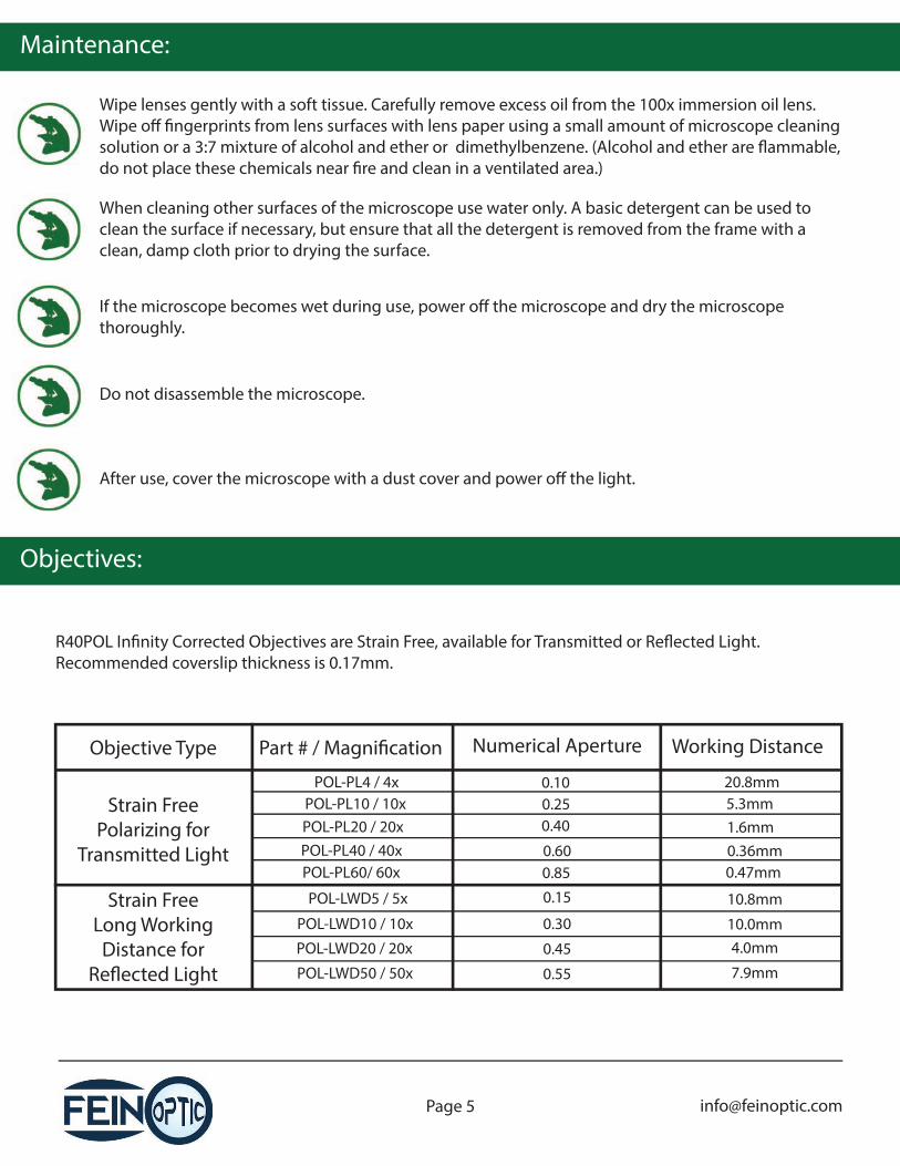
R40POL In�nity Corrected Objectives are Strain Free, available for Transmitted or Re�ected Light.Recommended coverslip thickness is 0.17mm.
Strain FreePolarizing for
Transmitted Light
Strain FreeLong Working
Distance for Re�ected Light
Objective Type Part # / Magni�cation Numerical Aperture Working Distance
POL-PL4 / 4xPOL-PL10 / 10xPOL-PL20 / 20xPOL-PL40 / 40xPOL-PL60/ 60x
0.100.250.40
0.600.85
20.8mm5.3mm1.6mm0.36mm0.47mm
POL-LWD10 / 10x
POL-LWD20 / 20x
POL-LWD5 / 5x
POL-LWD50 / 50x
0.15
0.30
0.45
10.8mm
10.0mm4.0mm
0.55 7.9mm
Microscope Assembly:
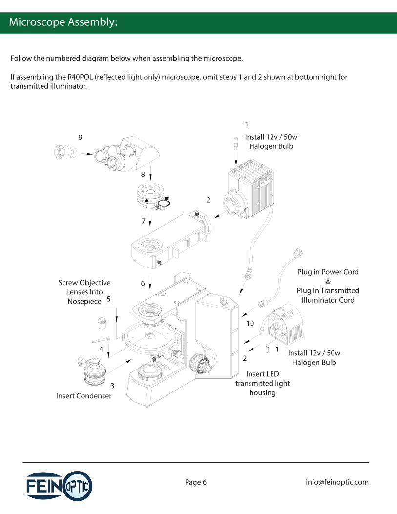
Follow the numbered diagram below when assembling the microscope.
If assembling the R40POL (re�ected light only) microscope, omit steps 1 and 2 shown at bottom right for transmitted illuminator.
1
Insert LED transmitted light
housing
2
Insert Condenser3
4
5
Install 12v / 50wHalogen Bulb
6
7
Screw Objective Lenses Into Nosepiece
8
Plug in Power Cord&
Plug In Transmitted Illuminator Cord
9
1 Install 12v / 50wHalogen Bulb2
10
Microscope Assembly:
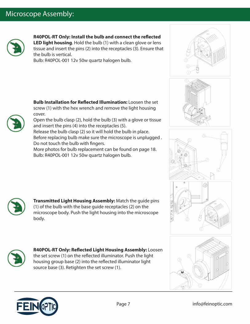
R40POL-RT Only: Install the bulb and connect the re�ected LED light housing. Hold the bulb (1) with a clean glove or lens tissue and insert the pins (2) into the receptacles (3). Ensure that the bulb is vertical.Bulb: R40POL-001 12v 50w quartz halogen bulb.
Bulb Installation for Re�ected Illumination: Loosen the set screw (1) with the hex wrench and remove the light housing cover. Open the bulb clasp (2), hold the bulb (3) with a glove or tissue and insert the pins (4) into the receptacles (5). Release the bulb clasp (2) so it will hold the bulb in place. Before replacing bulb make sure the microscope is unplugged .Do not touch the bulb with �ngers.More photos for bulb replacement can be found on page 18.Bulb: R40POL-001 12v 50w quartz halogen bulb.
Transmitted Light Housing Assembly: Match the guide pins (1) of the bulb with the base guide receptacles (2) on the microscope body. Push the light housing into the microscope body.
R40POL-RT Only: Re�ected Light Housing Assembly: Loosen the set screw (1) on the re�ected illuminator. Push the light housing group base (2) into the re�ected illuminator light source base (3). Retighten the set screw (1).
Microscope Assembly:
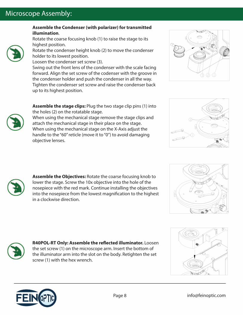
Assemble the Condenser (with polarizer) for transmitted illumination. Rotate the coarse focusing knob (1) to raise the stage to its highest position. Rotate the condenser height knob (2) to move the condenser holder to its lowest position.Loosen the condenser set screw (3).Swing out the front lens of the condenser with the scale facing forward. Align the set screw of the codenser with the groove in the condenser holder and push the condenser in all the way.Tighten the condenser set screw and raise the condenser back up to its highest position.
Assemble the stage clips: Plug the two stage clip pins (1) into the holes (2) on the rotatable stage.When using the mechanical stage remove the stage clips and attach the mechanical stage in their place on the stage.When using the mechanical stage on the X-Axis adjust the handle to the “60” reticle (move it to “0”) to avoid damaging objective lenses.
Assemble the Objectives: Rotate the coarse focusing knob to lower the stage. Screw the 10x objective into the hole of the nosepiece with the red mark. Continue installing the objectives into the nosepiece from the lowest magni�cation to the highest in a clockwise direction.
R40POL-RT Only: Assemble the re�ected illuminator. Loosen the set screw (1) on the microscope arm. Insert the bottom of the illuminator arm into the slot on the body. Retighten the set screw (1) with the hex wrench.
Microscope Assembly:
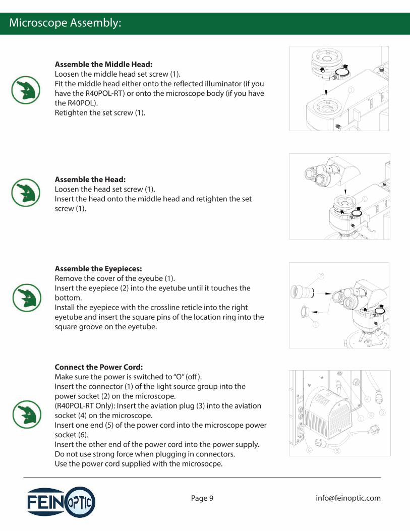
Assemble the Middle Head:Loosen the middle head set screw (1).Fit the middle head either onto the re�ected illuminator (if you have the R40POL-RT) or onto the microscope body (if you have the R40POL).Retighten the set screw (1).
Assemble the Head: Loosen the head set screw (1).Insert the head onto the middle head and retighten the set screw (1).
Assemble the Eyepieces: Remove the cover of the eyeube (1).Insert the eyepiece (2) into the eyetube until it touches the bottom.Install the eyepiece with the crossline reticle into the right eyetube and insert the square pins of the location ring into the square groove on the eyetube.
Connect the Power Cord:Make sure the power is switched to “O” (o�).Insert the connector (1) of the light source group into the power socket (2) on the microscope.(R40POL-RT Only): Insert the aviation plug (3) into the aviation socket (4) on the microscope.Insert one end (5) of the power cord into the microscope power socket (6).Insert the other end of the power cord into the power supply.Do not use strong force when plugging in connectors.Use the power cord supplied with the microsocpe.
Microscope Assembly:
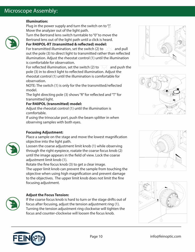
Focusing Adjustment:Place a sample on the stage and move the lowest magni�cation objective into the light path. Loosen the coarse adjustment limit knob (1) while observing through the right eyepiece, roatate the coarse focus knob (2) until the image appears in the �eld of view. Lock the coarse adjustment limit knob (1).Rotate the �ne focus knob (3) to get a clear image.The upper limit knob can prevent the sample from touching the objective when using high magni�cation and prevent damage to the objectives. The upper limit knob does not limit the �ne focusing adjustment.
Adjust the Focus Tension:If the coarse focus knob is hard to turn or the stage drifts out of focus after focusing, adjust the tension adjustment ring (1). Turning the tension adjustment ring clockwise will tighten the focus and counter-clockwise will loosen the focus knob.
Illumination:Plug in the power supply and turn the switch on to “|”.Move the analyzer out of the light path.Turn the Bertrand lens switch turntable to “0” to move the Bertrand lens out of the light path until a click is heard.For R40POL-RT (transmitted & re�ected) model:For transmitted illumination, set the switch (2) to and pull out the pole (3) to direct light to transmitted rather than re�ected illumination. Adjust the rheostat control (1) until the illumination is comfortable for observation.For re�ected illumination, set the switch (2) to and push the pole (3) in to direct light to re�ected illumination. Adjust the rheostat control (1) until the illumination is comfortable for observation.NOTE: The switch (1) is only for the the transmitted/re�ected model.The light directing pole (3) shows “R” for re�ected and “T” for transmitted light.For R40POL (transmitted) model:Adjust the rheostat control (1) until the illumination is comfortable.If using the trinocular port, push the beam splitter in when observing samples with both eyes.
Microscope Assembly:
Using the Eyeshields:Fold down the eyeshields on the eyepieces if wearing glasses to prevent the glasses from touching the eyepieces or the glass of the glasses.Fold open the eyeshields so that stray light does not disturb observation.
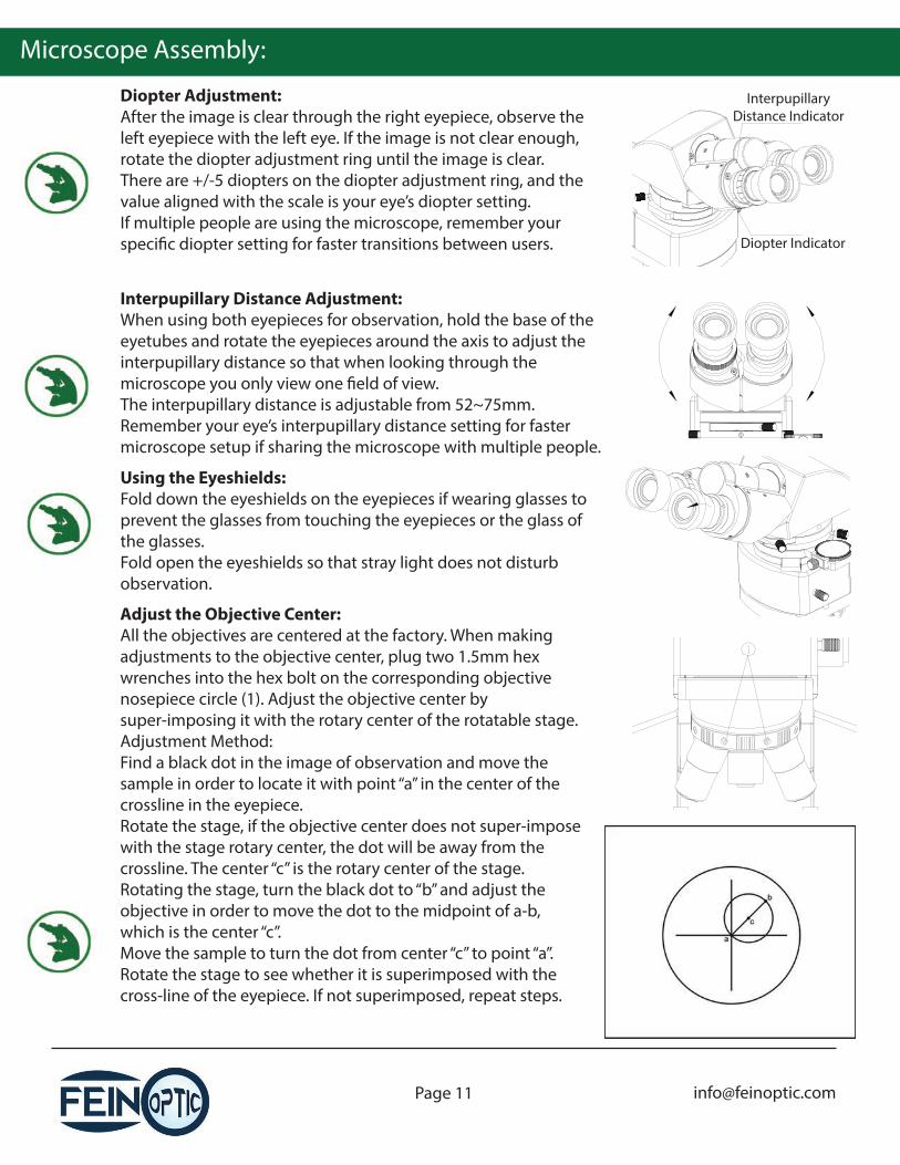
Adjust the Objective Center:All the objectives are centered at the factory. When making adjustments to the objective center, plug two 1.5mm hex wrenches into the hex bolt on the corresponding objective nosepiece circle (1). Adjust the objective center by super-imposing it with the rotary center of the rotatable stage.Adjustment Method:Find a black dot in the image of observation and move the sample in order to locate it with point “a” in the center of the crossline in the eyepiece.Rotate the stage, if the objective center does not super-impose with the stage rotary center, the dot will be away from the crossline. The center “c” is the rotary center of the stage.Rotating the stage, turn the black dot to “b” and adjust the objective in order to move the dot to the midpoint of a-b, which is the center “c”.Move the sample to turn the dot from center “c” to point “a”. Rotate the stage to see whether it is superimposed with the cross-line of the eyepiece. If not superimposed, repeat steps.
Diopter Adjustment:After the image is clear through the right eyepiece, observe the left eyepiece with the left eye. If the image is not clear enough, rotate the diopter adjustment ring until the image is clear.There are +/-5 diopters on the diopter adjustment ring, and the value aligned with the scale is your eye’s diopter setting.If multiple people are using the microscope, remember your speci�c diopter setting for faster transitions between users.
Interpupillary Distance Indicator
Diopter Indicator
Interpupillary Distance Adjustment:When using both eyepieces for observation, hold the base of the eyetubes and rotate the eyepieces around the axis to adjust the interpupillary distance so that when looking through the microscope you only view one �eld of view.The interpupillary distance is adjustable from 52~75mm.Remember your eye’s interpupillary distance setting for faster microscope setup if sharing the microscope with multiple people.
Microscope Assembly:
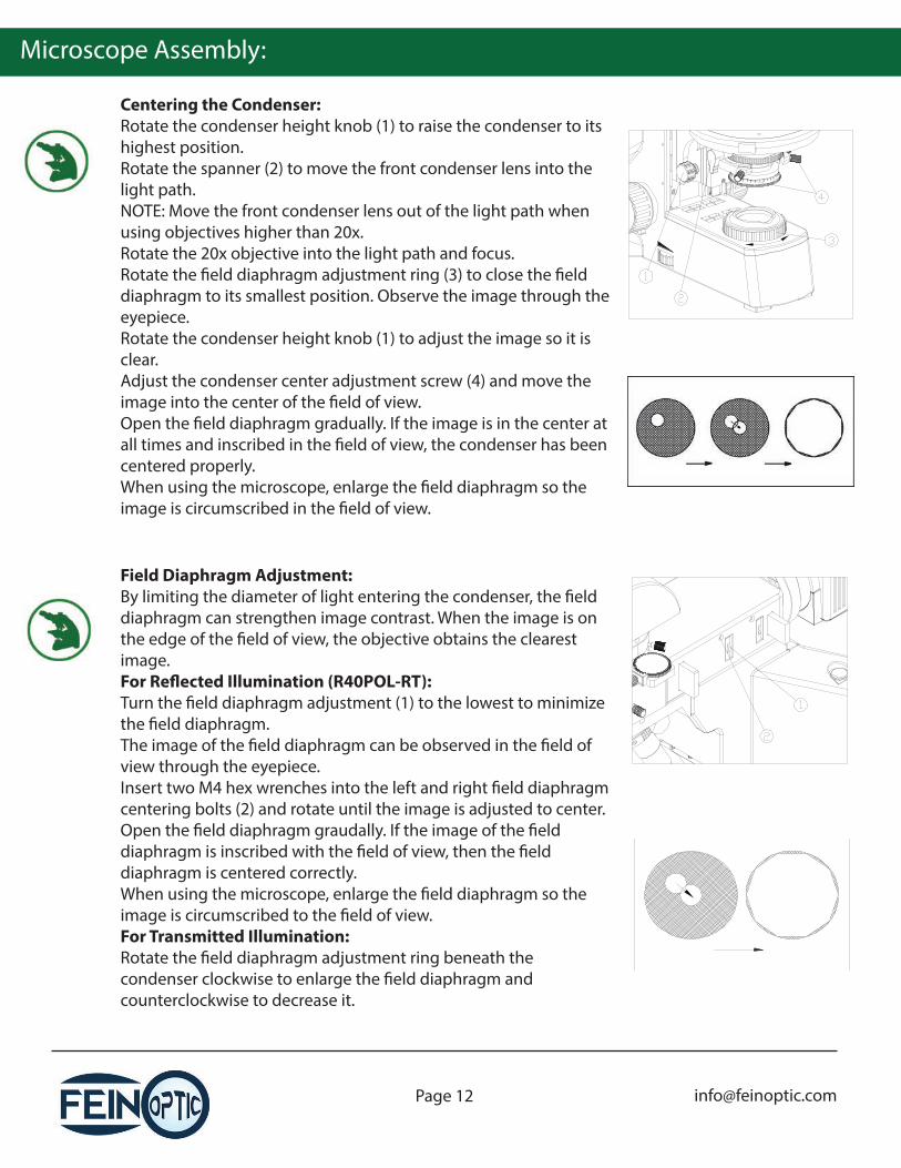
Centering the Condenser:Rotate the condenser height knob (1) to raise the condenser to its highest position. Rotate the spanner (2) to move the front condenser lens into the light path.NOTE: Move the front condenser lens out of the light path when using objectives higher than 20x.Rotate the 20x objective into the light path and focus.Rotate the �eld diaphragm adjustment ring (3) to close the �eld diaphragm to its smallest position. Observe the image through the eyepiece.Rotate the condenser height knob (1) to adjust the image so it is clear.Adjust the condenser center adjustment screw (4) and move the image into the center of the �eld of view.Open the �eld diaphragm gradually. If the image is in the center at all times and inscribed in the �eld of view, the condenser has been centered properly.When using the microscope, enlarge the �eld diaphragm so the image is circumscribed in the �eld of view.
Field Diaphragm Adjustment:By limiting the diameter of light entering the condenser, the �eld diaphragm can strengthen image contrast. When the image is on the edge of the �eld of view, the objective obtains the clearest image.For Re�ected Illumination (R40POL-RT):Turn the �eld diaphragm adjustment (1) to the lowest to minimize the �eld diaphragm.The image of the �eld diaphragm can be observed in the �eld of view through the eyepiece.Insert two M4 hex wrenches into the left and right �eld diaphragm centering bolts (2) and rotate until the image is adjusted to center.Open the �eld diaphragm graudally. If the image of the �eld diaphragm is inscribed with the �eld of view, then the �eld diaphragm is centered correctly.When using the microscope, enlarge the �eld diaphragm so the image is circumscribed to the �eld of view.For Transmitted Illumination:Rotate the �eld diaphragm adjustment ring beneath the condenser clockwise to enlarge the �eld diaphragm and counterclockwise to decrease it.
Microscope Assembly:
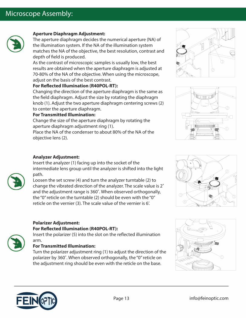
Aperture Diaphragm Adjustment:The aperture diaphragm decides the numerical aperture (NA) of the illumination system. If the NA of the illumination system matches the NA of the objective, the best resolution, contrast and depth of �eld is produced.As the contrast of microscopic samples is usually low, the best results are obtained when the aperture diaphragm is adjusted at 70-80% of the NA of the objective. When using the microscope, adjust on the basis of the best contrast.For Re�ected Illumination (R40POL-RT):Changing the direction of the aperture diaphragm is the same as the �eld diaphragm. Adjust the size by rotating the diaphragm knob (1). Adjust the two aperture diaphragm centering screws (2) to center the aperture diaphragm.For Transmitted Illumination:Change the size of the aperture diaphragm by rotating the aperture diaphragm adjustment ring (1).Place the NA of the condenser to about 80% of the NA of the objective lens (2).
Analyzer Adjustment:Insert the analyzer (1) facing up into the socket of the intermediate lens group until the analyzer is shifted into the light path.Loosen the set screw (4) and turn the analyzer turntable (2) to change the vibrated direction of the analyzer. The scale value is 2˚ and the adjustment range is 360˚. When observed orthogonally, the “0” reticle on the turntable (2) should be even with the “0” reticle on the vernier (3). The scale value of the vernier is 6’.
Polarizer Adjustment:For Re�ected Illumination (R40POL-RT):Insert the polarizer (5) into the slot on the re�ected illumination arm.For Transmitted Illumination:Turn the polarizer adjustment ring (1) to adjust the direction of the polarizer by 360˚. When observed orthogonally, the “0” reticle on the adjustment ring should be even with the reticle on the base.
Microscope Assembly:
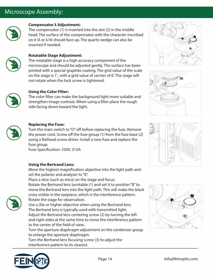
Compensator λ Adjustment:The compensator (1) is inserted into the slot (2) in the middle head. The surface of the compensator with the character inscribed on it (λ or λ/4) should face up. The quartz wedge can also be inserted if needed.
Replacing the Fuse:Turn the main switch to “O” o� before replacing the fuse. Remove the power cord. Screw o� the fuse group (1) from the fuse base (2) using a �athead screw driver. Install a new fuse and replace the fuse group.Fuse Speci�cation: 250V, 315A
Using the Bertrand Lens:Move the highest magni�cation objective into the light path and set the polarier and analyzer to “0”.Place a slice (such as mica) on the stage and focus.Rotate the Bertrand lens turntable (1) and set it to position “B” to move the Bertrand lens into the light path. This will make the black cross visible in the eyepiece, which is the interference pattern. Rotate the stage for observation.Use a 20x or higher objective when using the Bertrand lens.The Bertrand lens is typically used with transmitted light.Adjust the Bertrand lens centering screw (2) by turning the left and right sides at the same time to move the interference pattern to the center of the �eld of view.Turn the aperture diaphragm adjustment on the condenser group to enlarge the aperture diaphragm.Turn the Bertrand lens focusing screw (3) to adjust the interference pattern to its clearest.
Rotatable Stage Adjustment:The rotatable stage is a high accuracy component of the microscope and should be adjusted gently. The surface has been printed with a special graphite coating. The grid value of the scale on the stage is 1˚, with a grid value of vernier of 6’. The stage will not rotate when the lock screw is tightened.
Using the Color Filter:The color �lter can make the background light more suitable and strengthen image contrast. When using a �lter place the rough side facing down toward the light.
Microscope Assembly:
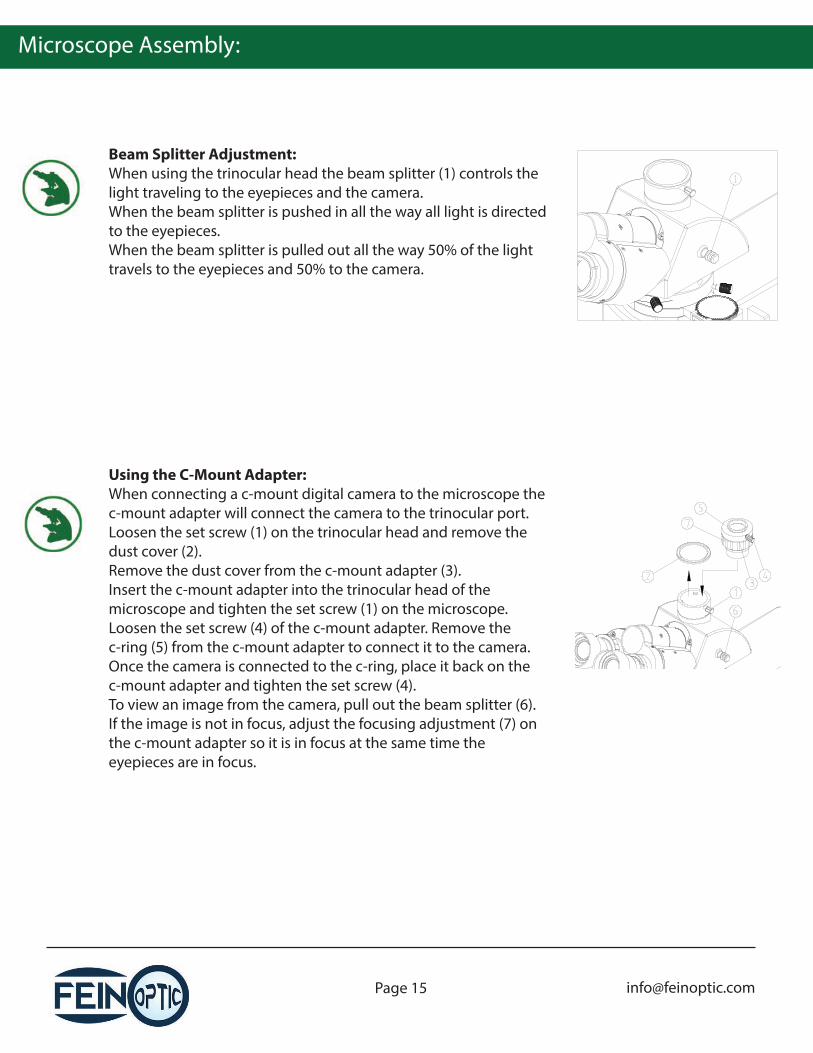
Beam Splitter Adjustment:When using the trinocular head the beam splitter (1) controls the light traveling to the eyepieces and the camera.When the beam splitter is pushed in all the way all light is directed to the eyepieces.When the beam splitter is pulled out all the way 50% of the light travels to the eyepieces and 50% to the camera.
Using the C-Mount Adapter:When connecting a c-mount digital camera to the microscope the c-mount adapter will connect the camera to the trinocular port.Loosen the set screw (1) on the trinocular head and remove the dust cover (2).Remove the dust cover from the c-mount adapter (3). Insert the c-mount adapter into the trinocular head of the microscope and tighten the set screw (1) on the microscope.Loosen the set screw (4) of the c-mount adapter. Remove the c-ring (5) from the c-mount adapter to connect it to the camera.Once the camera is connected to the c-ring, place it back on the c-mount adapter and tighten the set screw (4).To view an image from the camera, pull out the beam splitter (6).If the image is not in focus, adjust the focusing adjustment (7) on the c-mount adapter so it is in focus at the same time the eyepieces are in focus.
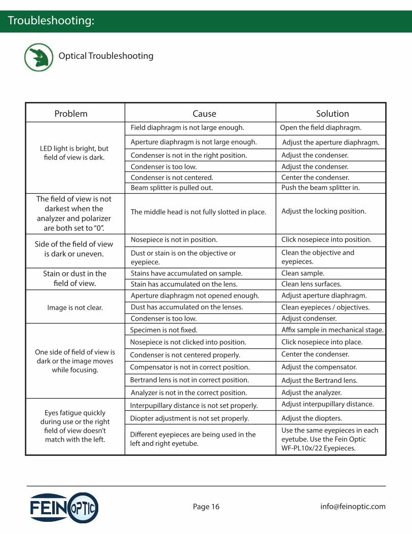
Troubleshooting:
Optical Troubleshooting
Problem Cause Solution
LED light is bright, but �eld of view is dark.
Field diaphragm is not large enough.
Aperture diaphragm is not large enough.
Condenser is not in the right position.
Open the �eld diaphragm.
Adjust the aperture diaphragm.
Adjust the condenser.
The �eld of view is not darkest when the
analyzer and polarizer are both set to “0”.
The middle head is not fully slotted in place. Adjust the locking position.
Side of the �eld of view is dark or uneven.
Nosepiece is not in position.
Dust or stain is on the objective or eyepiece.
Click nosepiece into position.
Clean the objective and eyepieces.
Image is not clear.
Stains have accumulated on sample. Clean sample.
Dust has accumulated on the lenses. Clean eyepieces / objectives.
Condenser is too low. Adjust condenser.
Analyzer is not in the correct position. Adjust the analyzer.
One side of �eld of view is dark or the image moves
while focusing.
Specimen is not �xed. A�x sample in mechanical stage.
Nosepiece is not clicked into position. Click nosepiece into place.
Center the condenser.Condenser is not centered properly.
Eyes fatigue quickly during use or the right
�eld of view doesn’t match with the left.
Interpupillary distance is not set properly. Adjust interpupillary distance.
Diopter adjustment is not set properly. Adjust the diopters.
Di�erent eyepieces are being used in the left and right eyetube.
Use the same eyepieces in each eyetube. Use the Fein Optic WF-PL10x/22 Eyepieces.
Beam splitter is pulled out. Push the beam splitter in.
Condenser is too low. Adjust the condenser.Condenser is not centered. Center the condenser.
Stain or dust in the �eld of view. Stain has accumulated on the lens. Clean lens surfaces.
Aperture diaphragm not opened enough. Adjust aperture diaphragm.
Compensator is not in correct position. Adjust the compensator.
Bertrand lens is not in correct position. Adjust the Bertrand lens.
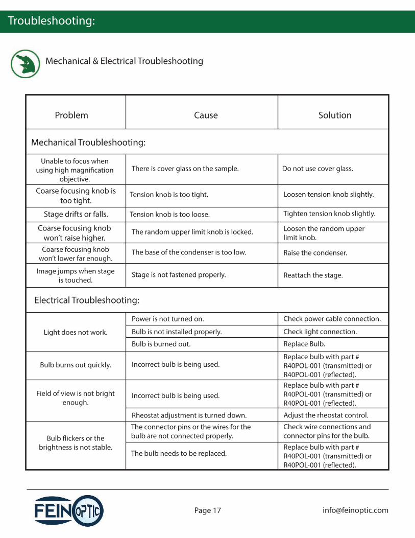
Troubleshooting:
Mechanical & Electrical Troubleshooting
Problem Cause Solution
Unable to focus when using high magni�cation
objective.There is cover glass on the sample. Do not use cover glass.
Stage drifts or falls. Tension knob is too loose.
The random upper limit knob is locked.
Tighten tension knob slightly.
Loosen the random upper limit knob.
Coarse focusing knob won’t lower far enough.
The base of the condenser is too low. Raise the condenser.
Stage is not fastened properly. Reattach the stage.
Power is not turned on. Check power cable connection.
Bulb is not installed properly. Check light connection.
Bulb is burned out. Replace Bulb.
The connector pins or the wires for the bulb are not connected properly.
Check wire connections and connector pins for the bulb.Bulb �ickers or the
brightness is not stable.
Coarse focusing knob is too tight.
Tension knob is too tight. Loosen tension knob slightly.
Coarse focusing knob won’t raise higher.
Image jumps when stage is touched.
Light does not work.
Field of view is not bright enough.
Rheostat adjustment is turned down. Adjust the rheostat control.
Bulb burns out quickly. Incorrect bulb is being used.Replace bulb with part # R40POL-001 (transmitted) or R40POL-001 (re�ected).
Incorrect bulb is being used.
The bulb needs to be replaced.
Mechanical Troubleshooting:
Electrical Troubleshooting:
Replace bulb with part # R40POL-001 (transmitted) or R40POL-001 (re�ected).
Replace bulb with part # R40POL-001 (transmitted) or R40POL-001 (re�ected).
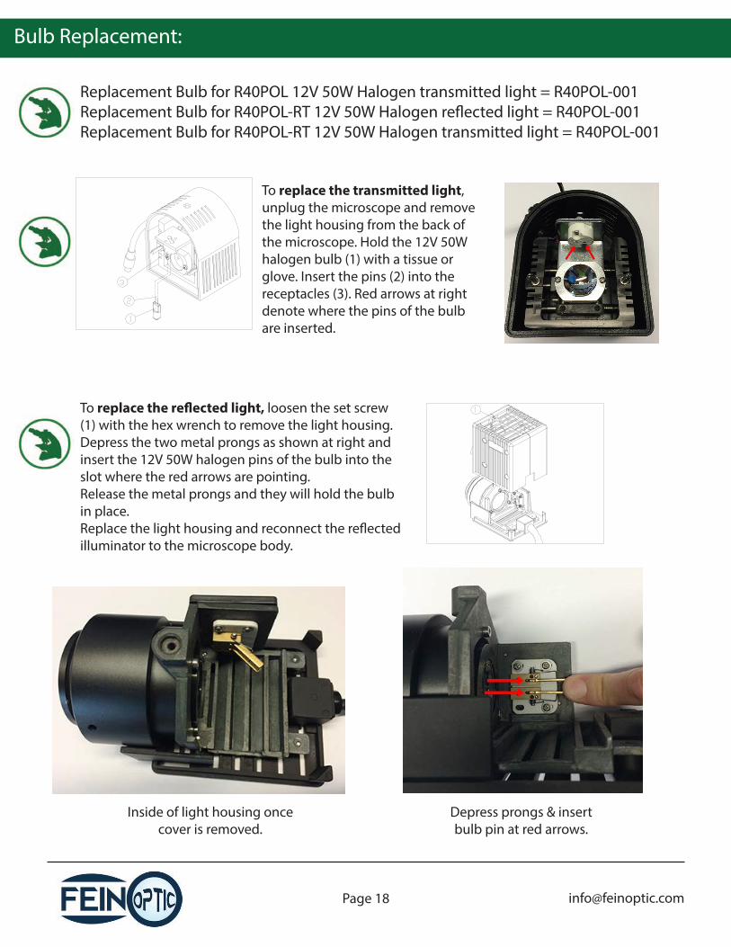
Bulb Replacement:
Replacement Bulb for R40POL 12V 50W Halogen transmitted light = R40POL-001Replacement Bulb for R40POL-RT 12V 50W Halogen re�ected light = R40POL-001Replacement Bulb for R40POL-RT 12V 50W Halogen transmitted light = R40POL-001
To replace the transmitted light, unplug the microscope and remove the light housing from the back of the microscope. Hold the 12V 50W halogen bulb (1) with a tissue or glove. Insert the pins (2) into the receptacles (3). Red arrows at right denote where the pins of the bulb are inserted.
To replace the re�ected light, loosen the set screw (1) with the hex wrench to remove the light housing.Depress the two metal prongs as shown at right and insert the 12V 50W halogen pins of the bulb into the slot where the red arrows are pointing.Release the metal prongs and they will hold the bulb in place.Replace the light housing and reconnect the re�ected illuminator to the microscope body.
Inside of light housing once cover is removed.
Depress prongs & insert bulb pin at red arrows.


