United StatesDepartment ofAgriculture
Forest Service
ForestProductsLaboratory
State andPrivateForestry
GeneralTechnicalReportFPL-IMP-GTR-1
Quality Drying ofSoftwood LumberGuidebook–ChecklistMichael R. MilotaR. Sidney BooneJeanne D. DanielsonDean W. Huber
Lumber Drying Program
Contents
Page
Introduction . . . . . . . . . . . . . . . . . . . . . . . . . . .
Guidebook–Checklist
Rating System
Overviewing the Kilns
Studying One Kiln
Monitoring the Effects of Changes
Using the Checklist . . . . . . . . . . . . . . . . . .
Safety Precautions . . . . . . . . . . . . . . . . . . . . . .
Guidebook for Quality Drying of
Softwood Lumber . . . . . . . . . . . . . . . . . . . .
Standard Operating Practices
Control Room . . . . . . . . . . . . . . . . . . . . . . .
Fan Deck and Kiln Roof . . . . . . . . . . . . . . .
Yard Area . . . . . . . . . . . . . . . . . . . . . . . . .
Inside an Empty Kiln
While Preparing Charges and Loading
the Kiln . . . . . . . . . . . . . . . . . . . . . . . . .
During Kiln Startup and Operation . . . . . . .
After Drying Is Completed . . . . . . . . . . . . .
Evaluate Stacking and Its Effect
on Drying Quality
Drying Defects and Drying Problems
Reported
Checklist for Quality Drying of
Softwood Lumber . . . . . . . . . . . . . . . . . . . .
Standard Operating Practices . . . . . . . . . .
Control Room . . . . . . . . . . . . . . . . . . . . . . .
Fan Deck and Kiln Roof . . . . . . . . . . . . . . .
Yard Area . . . . . . . . . . . . . . . . . . . . . . . . .
Inside an Empty Kiln . . . . . . . . . . . . . . . . .
While Preparing Charges and
Loading the Kiln . . . . . . . . . . . . . . . . . .
During Kiln Startup and Operation . . . . . .
After Drying Is Completed . . . . . . . . . . . . .
Evaluate Stacking and Its Effect
on Drying Quality
Drying Defects and Drying Problems
Reported . . . . . . . . . . . . . . . . . . . . . . .
Appendix 1—Summary Checklist for
Quality Drying of Softwood Lumber . . . . . .
Appendix 2—Checklist Arranged by
Drying System Components . . . . . . . . . . .
. . . . . . . . . . . . . . . . . . . .
. . . . . . . . . . . . . . . . . . . . . .
. . . . . . . . . . . . . . . .
. . . . . . . . . . . . . . . . . . . .
. . . . . . .
. . . . . . . . . .
. . . . . . . . . . . . . . . . .
. . . . . . . . . . . . . . . . . . . . . . .
. . . . . . . . . . . . . . . . . . . . . .
. . . . . . . . . . . . . . . . .
1
2
2
2
2
2
2
3
4
4
8
10
13
14
16
18
19
23
28
32
32
34
35
36
37
38
39
39
40
42
44
48
Abstract
The IMPROVE Lumber Drying Program is intended toincrease awareness of the lumber drying system as acritical component in the manufacture of qualitylumber. One objective of the program is to provideeasy-to-use tools that a kiln operator can use tomaintain an efficient kiln operation and thereforecontribute to lumber drying quality. This report is onecomponent of the IMPROVE Program. It contains aguidebook–checklist for drying quality softwood thatkiln operators or management can use to readilyevaluate how well their operations rate on thosefactors that most strongly affect drying quality, withparticular emphasis on kiln operation and mainte-nance and lumber handling. Appendix 1 contains asummary checklist for easy duplication and filing.Appendix 2 contains the same checklist items;however, the information is arranged by dryingsystem components for convenience in checkingindividual components.
Acknowledgment
The IMPROVE program is a cooperative effort ofthe Forest Products Laboratory and State & PrivateForestry, U.S. Department of Agriculture, ForestService. In addition, several universities, currentlyOregon State University and the University of Wis-consin, are cooperating on this project.
September 1991______________________________________________________________________________
Milota, Michael, R.; Boone, R. Sidney; Danielson, Jeanne D.;Huber, Dean W. 1991. Quality Drying of Softwood Lumber:Guidebook and Checklist.
Gen. Tech. Rep. FPL-IMP-GTR-1. Madison, WI: U.S. Departmentof Agriculture, Forest Service, Forest Products Laboratory. 50 p.
A limited number of free copies of this publication are available tothe public from the Forest Products Laboratory, One GiffordPinchot Drive, Madison, WI 53705-2398. Laboratory publicationsare sent to more than 1,000 libraries in the United States andelsewhere.
The Forest Products Laboratory is maintained in cooperation withthe University of Wisconsin.
1
Introduction
The IMPROVE Lumber Drying Program is intendedto increase awareness of the lumber drying systemas a critical component in the manufacture of qualitylumber. The goals of the program are to helpsawmill personnel improve lumber drying quality byidentifying sources of drying losses, both grade andvolume. Operation of the dry kiln is only one factorthat determines lumber drying quality. Each step ofthe lumber manufacturing process affects lumberdrying quality—from the time logs are felled in thewoods until the lumber leaves the unstacker afterdrying. The IMPROVE Lumber Drying Program isdesigned to systematically evaluate the dryingoperation and identify areas contributing to poorlumber product quality, both in the drying operationstage and at every prior stage of lumber manufac-ture. Therefore, causes of drying quality losses canbe corrected at their source, rather than trying tocompensate for them in the kiln.
A package of analytical tools for the IMPROVEprogram is under development. These tools willmeasure and improve processing efficiency andproduct quality in sawmills, veneer mills, and ply-wood plants. Methods will be provided to evaluatehow effectively logs are being converted into endproducts, to identify opportunities to increaseproduct yield and value, and to predict the results ofproposed improvements.
One objective of the IMPROVE Lumber DryingProgram is to provide easy-to-use tools that a kilnoperator can use routinely in daily work around thekilns without having to perform special studies or
interfering with production. To help fulfill this objec-tive, this report contains a complete guidebook–checklist for drying quality softwood lumber. Theguidebook explains the importance of each item onthe checklist and describes how to evaluate it. Ifquestions arise while using the checklist, you canrefer to the guidebook for a detailed explanation.The guidebook also provides a quick reference ondrying quality. Kiln operators can use the checklistto readily evaluate how well their operations rate onthose factors that most strongly affect drying quality.Particular emphasis is given to kiln operation as wellas maintenance and lumber handling. In addition tothe guidebook and checklist, Appendix 1 contains asummary checklist for easy duplication and filing.Appendix 2 contains the same checklist items butlisted according to drying system components forconvenience in checking individual components.
The guidebook–checklist is intended to be used witheither steam-heated or direct-fired kilns. It is notpractical or our intent to cover all the detailedcomponents of the lumber drying system. Weencourage you to use the guidebook–checklist andadapt it to your individual situations. Many othermaintenance and operating factors are also impor-tant, but these do not have as direct a bearing ondrying quality, although they should not be ne-glected. Chapter 4 of the "Dry Kiln Operator’sManual" (DKOM)1 contains maintenance checklistsand discusses many factors of kiln maintenance.Kiln manufacturers can also supply maintenancechecklists and additional information.
1USDA. 1991. Dry kiln operator's manual. Agric. Handb. 188.Washington, DC: U.S. Department of Agriculture, Forest Service.
Guidebook–Checklist
Michael R. Milota , Assistant ProfessorOregon State UniversityCorvallis, Oregon
R. Sidney Boone, Research Forest Products TechnologistJeanne D. Danielson, Supervisory Research Forest Products TechnologistForest Products LaboratoryMadison, Wisconsin
Dean W. Huber, Program Manager, Forest Products Utilization and MarketingState & Private Forestry, Region 5San Francisco, California
Quality Drying of Softwood Lumber
2
Guidebook –Checklist
The guidebook–checklist can be used three ways:(1) to make an overview of the entire kiln operation;(2) to closely check or monitor a particular kiln that issuspected of causing drying problems; and (3) tomonitor the effects of improvements by providing a“baseline” for later comparison.
The checklist is a working tool, and to get the mostvalue from it, you must physically examine variousequipment and systems around the kiln. Only byactually observing the items on the checklist can youaccurately assess your kiln operation. The checklistis arranged so that items can be checked together ateach location around the kiln. For example, allobservations of valves and controls normally foundin the control room are listed together on the check-list, and checks of stacking and stickering are doneat the dry end. A shortened version or summary ofthe checklist (without the rating key) is given inAppendix 1. We suggest you make copies of thisshortened version to write on and keep with your kilnrecords.
For convenience in checking individual systems,such as air circulation or heating, a summary of thechecklist items arranged by drying system compo-nents is given in Appendix 2.
Rating System
Each item on the checklist has a rating key based ona scale from 4 (high) to 1 (low). Each level of ratingis further described in the guidebook. The highrating of 4 is intended to be attainable, but challeng-ing, for most of the industry. The low score of 1indicates a strong need for improvement. In a well-maintained and well-operated kiln, most of theratings should be 4 and 3.
Overviewing the Kilns
When using the checklist as an overview, it is notnecessary to look at all items in the same kiln. Youmay complete the checklist items related to anempty kiln in one kiln, then do the items related to arunning kiln in a second kiln, and check the dry endas a third kiln is being unloaded. This overview canbe completed in several hours or less.
Studying One Kiln
Past experience or the overview checklist maysuggest one particular kiln is causing drying qualityproblems. You can also use the checklist to evalu-ate that one kiln for all steps from loading through
unloading. You will have to keep the checklist foreach step of the drying cycle as it is completed.
Monitoring the Effects of Changes
If changes are made that affect the drying operation,either at the kiln or in the prior lumber handling, youcan use the checklist to monitor how these changesaffected drying quality. Rate the kiln or operationbefore the changes are made and save the check-list. Repeat the checklist rating after the changeshave been made. You can then compare the beforeand after ratings for the effect of these changes.
Using the Checklist
The checklist is arranged so that items are groupedtogether by the area of the kiln or yard where theyare checked. Begin in the kiln control room. Thefirst series of questions ask about standard operat-ing procedures. These relate to maintenanceprocedures and maintenance schedules,recordkeeping, and communications. These itemsshould be checked regularly to prevent problems orcorrect them before they become serious.
In the control room, you are asked to check thesteam valves and controls to see that these areworking and that the desired schedule is actuallyfollowed.
From the control room, go to the fan deck and thekiln roof. Here, check the fans, heating coils, andvents for proper working order.
In the kiln yard area, check the stickers and bolstersfor uniform sizing. Use dial calipers or a micrometer,if possible, to check sticker and bolster thickness.
Then, find an empty kiln and check for condensa-tion, clean reheat coils, and a good water supply tothe wet-bulb. Next, turn on the steam to check thesteam pipes and heating coils for steam and waterleaks, and turn on the steam spray to check it forleaks and uniform distribution of steam.
From the empty kiln move to a kiln that is beingloaded. Check the loading practices as packagesare loaded on the kiln trucks or load supports. Afterthat kiln is loaded, check that the package loadingwill ensure proper airflow through the packages.During startup, check the traps and the airflowacross the wet-bulb. While the kiln is operating,check for drainage or leaks and confirm that the fanreversals are actually occurring.
From the kiln being loaded, go to a kiln that is readyto be unloaded and check the baffles to see if they
3
were placed to properly direct airflow through theload and remained securely in place during drying.Then, spot check the moisture content (MC) of theload. Before the load is broken down, check thestickering and stacking and check for drying defects.At this time, you can see how the stickering andstacking affect warp and other drying defects. It maybe difficult to see drying defects in boards that areaway from the package sides. If the checklist reviewpoints to problems with drying defects, watch thepackages being broken down and talk with thegraders to get more information.
Safety Precautions
Be extremely careful and observe safety precautionsas you use this checklist. It is not possible to list allthe potential hazards; some are listed below.
(1) Be careful of burns from live steam whenchecking traps, steam valves, and steam spraylines.
(2) LOCK OUT fan switches when checking itemson the fan deck. DO NOT go on the fan deckwhen the fans are turning.
(3) Tell someone in the immediate area that youare entering a loaded kiln and preferably havethat person nearby, especially if the kiln isoperating. Know how to move the end bafflesand operate the door latches in the dark.Watch the footing when walking in the kiln.
(4) DO NOT enter a kiln when the wet-bulbtemperature is greater than 120°F.
(5) Use a handkerchief or rag to check air directionon fan reversals. This same technique shouldbe used when looking for leaks at vents oraround doors as air from exhaust vents andleaks can be extremely hot when high-temperature schedules are used.
(6) Watch for unstable lumber piles or looseboards and for protruding kiln stickers.
4
Guidebook for Quality Drying of Softwood Lumber
For each item in the checklist section, the following descriptions summarize how that item affects drying qualityand why it is important. Additional descriptions are provided in the "Dry Kiln Operator’s Manual" (DKOM). TheDKOM is referenced throughout this guidebook when it contains additional helpful information. Also refer toDKOM for needed definitions of terms.
Standard Operating Practices
1. Maintenance and Inspection
1.a. Equipment above fan deck inspected regularly
Identifying maintenance problems so that repairs can be scheduled is preferable to having equipment failures. Small repairs are usually less costly, particularly in the fan system where vibrations and breakage can cause major damage. Regular inspection of fans and motors will help identify problems leading to non-uniform airflow. This, in turn, will help control MC variability.
Rating 4 - Fans, motors, bearings, shafts, and other equipment inspected monthly (in high-temperature kilns [dry-bulb temperature exceeds 212°F] inspected weekly) 3 - Inspected quarterly (in high-temperature kilns, inspected monthly) 2 - Inspected annually (in high-temperature kilns, inspected quarterly) 1 - Inspections are not regularly made
1.b. Air velocity checks made regularly
Air velocity must be sufficient to bring heat to the lumber and remove evaporated moisture. It should also be uniform throughout the kiln so that drying occurs as equally as possible in all packages. Regular air velocity checks help identify obstructions to airflow and fan maintenance problems that lead to uneven drying. High-temperature kilns are designed with high air speeds, 1,000 ft/min or more. Uniformity of airflow is extremely important to uniform drying in high-temperature drying. More frequent checks are recommended than in conventional temperature kilns.
Rating 4 - Checked semiannually (in high-temperature kilns [dry-bulb temperature exceeds 212°F] checked quarterly) 3 - Checked when there is a problem (in high-temperature kilns, checked semiannually) 2 - Checked when the kiln was new or rebuilt or when a problem occurs 1 - Never checked
1.c. Traps checked for proper operation and plumbed for ease of checking
Traps are vital to remove condensed water from the heating system. Traps should be sized large enough to handle the peak load during kiln startup but not pass excessive steam late in the schedule when steam demand is low. Even a properly designed and installed trap can malfunction due to dirt. Installing screens ahead of the traps and flushing them every 30 days can help prevent malfunctions.
If condensate is not removed from the heating coils, they will fill with condensed water, keeping steam from entering. To ensure even heating throughout the kiln, the traps should be checked every charge. Good kiln design calls for placing traps where they are readily accessible (but as close to the coils as practical) for ease of checking while the kiln is running.
Rating 4 - Traps are checked for condensate backup and passing steam every charge; traps are properly sized for the load 3 - Traps are checked at least every 30 days or traps are not quite large enough to handle condensate during startup 2 - Traps are checked at least every six months or traps are very undersized 1 - Traps are rarely checked, inaccessible, not plumbed for regular checks
5
1.d. Air supply to kiln controllers checked at regular intervals
Compressed air is used to operate many kiln controllers and/or valves. Many pneumatic controller problems can be traced to dirt or moisture in the air supply. It is estimated that anywhere from 25% to as much as 40% of controller problems originate from poor air supply quality.
Rating 4 - Air filters and compressors are checked and drained every charge 3 - Inspected on some other schedule but at least monthly 2 - Inspected only when a problem is suspected 1 - Inspected only when the controller or air supply does not work
1.e. Regular maintenance program for steam valves
Faulty valves can prevent steam from entering the coils when it is needed or allow steam to enter when it is not needed. Regular inspection of the valves is one way to prevent problems or identify them while they are small, instead of waiting for wet or overdried lumber to indicate a problem exists. Inspection should check that valves open and close completely and, if applicable, that they open in proportion to the signal from the controller.
Rating 4 - Valves are inspected at least every 90 days 3 - Inspected at least annually 1 - Inspected only when a problem is suspected
1.f. Regular calibration of each temperature sensing device and indicator
Accurate sensing of temperature is essential to maintaining the scheduled temperature in the kiln. When temperature sensors are out of calibration, the temperature may be higher than desired, leading to overdrying and degrade, or lower than desired, which increases drying time or causes wet lumber. Accurate temperature sensing is also necessary so that the same schedule can be run repeatedly in the same kiln or from one kiln to the next. A temperature difference as little as 5°F will cause significantly different drying rates.
The simplest way to check the operation of the temperature sensors is to attach a thermocouple to eachsensor and see how closely the thermocouple reading agrees with the kiln’s recorder. When doing this,the bare end of the thermocouple wire should not touch metal, such as the sensor bulb, but should belocated as close to the sensor as possible. On the wet-bulb, the thermocouple should be located underthe wick at the tip of the sensor. It is good practice to coat the tip of this thermocouple with silicone toelectrically isolate it from the bulb and the water. The thermocouple wires should be routed so that it iseasy to compare the thermocouple readings to the temperature indicated on the recorder/controller. Somemills permanently install the wires to facilitate regular checks.
Another way to check the operation of the temperature sensors and the recording device is to use a stirredhot water bath (bucket) as described in Chapter 4 of the DKOM. An accurate glass thermometer is used tomeasure the bath temperature. The sensor is submerged in the bath. One person stirs the bath whileanother reads the recorder. At least 5 to 10 minutes of stirring are needed for the system to come to asteady temperature. For vapor or liquid-vapor bulbs, the height of the bucket should be the same as thebulb location in the kiln. This check of the calibration is usually done throughout the range of the instru-ment and is more thorough, but is also more difficult, than the thermocouple method. In addition, the kilnmust be shut down.
The calibration procedure is the same for both dry- and wet-bulb sensors. Chapters 3 and 4 of the DKOMgive additional information about calibrating sensors.
Rating 4 - Calibration checks are made at least every 6 months; results are recorded and filed 3 - Calibration checks are made more than 6 months apart, but at least every 2 years 2 - Calibration is checked when a problem is suspected 1 - Not calibrated since installation
6
1.g. Wet-bulb wicks changed on a regular schedule
If the wet-bulb wick is not clean, it will not give the true wet-bulb temperature. The dirt can be from dust, volatiles from the wood, or salts in the water. For best wet-bulb control, the wick should be changed with every new charge of lumber.
Rating 4 - New wick(s) used every charge 3 - Wick(s) changed regularly 2 - Wick(s) changed when they are dirty 1 - Wick(s) changed rarely
2. Moisture Content Monitoring and Recordkeeping
2.a. Moisture content checks on each charge made as standard practice
The MC should be checked on dry lumber as a standard operating practice. The number of samples should be sufficient to give a good estimate of the average MC of the charge and how much individual boards vary from the average. Some system for recording and storing these records should exist. A good history of MC data is often helpful in locating wet or dry zones in the kiln due to uneven drying conditions.
Rating 4 - At least four boards checked in each package that the operator can reach 3 - Three boards per package are checked 2 - Two boards per package at least are checked 1 - One board or less per package is checked
2.b. In-kiln MC monitoring equipment is used when available
Equipment that tells the operator information about the MC of the lumber in the kiln is valuable in achieving the target MC. The equipment for this is often metal strips placed in sticker openings, resistance pins placed in selected boards, or some feedback from the control system such as temperature drop across the load or steam demand.
Rating 4 - In-kiln sensors used according to the manufacturer’s instructions 2 - In-kiln sensors used but some operators do not pay attention to them 1 - In-kiln sensors available but not used
2.c. Control charts are saved and filed for reference
Good records should be maintained in any production operation. They are valuable in tracing problems that arise slowly over time or answering customer complaints. The date and time in, date and time out, product, species, and other information that may be historically important should be recorded on each control chart. This might include unusual weather, maintenance problems, unusual loading of the kiln, or a new schedule. Reports of defects or degrade should be saved with the control charts as an aid to identifying their cause. These should be filed so they can be easily retrieved, for example by kiln number or by product, if there is a need.
Rating 4 - Complete sets of records are kept and retrieval is easy 3 - Available information is kept for a while in a manner that allows retrieval 2 - Charts are kept but finding records for a charge of lumber dried 6 months ago is difficult 1 - No information is kept
7
2.d. Records of MC checks are kept with control charts
It is a good idea to also record and store moisture information with the control charts, thus giving a complete history of drying for a particular kiln. This history can be particularly useful in tracking moisture variation problems that affect one kiln or part of a kiln.
Rating 4 - Complete records are filed together for easy retrieval 3 - Records of MC checks are kept but not filed with control charts 1 - Records are not kept
3. Discussion and Feedback from Planer Operators and Graders
3.a. Regular communication with planer operators and graders
Regular communication with planer operators and graders allows the kiln operator to pass along important information, such as unusual conditions of a particular charge. It also helps the kiln operator to be constantly aware of drying quality. The planer operators and graders can provide rapid feedback to know if changes in schedules or other kiln operating practices have improved grade and machining quality. They can also help discover problems with the kilns as they develop, before they become serious.
Rating 4 - Communicate regularly, at least once a week 3 - Communicate only during scheduled production meetings 2 - Communicate only when there are problems 1 - Communicate rarely
4. Learning Opportunities
4.a. Opportunities to visit other sites and meet other operators
Meeting with other kiln operators and visiting their operations provides a chance to discuss common problems, gain confidence in your own work, develop new skills, and learn how others may do things differently.
Rating 4 - Visit other sites three or more times per year 3 - Visit other sites twice a year 2 - Visit other sites once a year 1 - Never visit other sites
4.b. Attend Dry Kiln Association meetings and drying workshops
Dry Kiln Association meetings and drying workshops are some of your best sources of up-to-date information on the latest techniques and equipment. Attending them also gives you a chance to meet other operators and equipment suppliers and learn more about their approaches to similar situations.
Rating 4 - Attend Dry Kiln Association meetings yearly and have attended at least one workshop 3 - Regularly attend meetings but have never been to a workshop 2 - Attend meetings every 2 or 3 years 1 - Never attend meetings or workshops
8
Control Room
5. Valves Operate Properly
5.a. Steam heat valves fully open and close
It is important for the heat valves to open and close to the position signaled by the controller. This is particularly important for the fully closed position so that the kiln does not heat above setpoint. Also, steam leaking under the valve seat will erode and permanently damage valve parts. It is important for the valve to move to the fully open position so that maximum steam flow can be achieved when it is needed.
Listen to the valve when it should be in the fully closed position. If steam can be heard passing through it, then the valve is not fully closed. A mechanic’s stethoscope can be helpful for this, particularly on low pressure systems. A way to check for fully closed valves during downtime is to make sure that the valves are receiving the signal for the fully closed position. Then, after sufficient time has elapsed (2 hours), check the pipes leading from the valves to the heating coils to see if they are hot. Heat indicates the valve is leaking steam and not fully closed. The recorder chart can also give an indication that the valve is leaking. Late in the drying schedule when the lumber is hot and heat demand is low, the controller will signal the valve to close when it senses the temperature is above setpoint. A leaking steam valve (not fully closed) will allow steam to enter the kiln. Therefore, the recorder chart will show a slow rise in dry-bulb temperature above the setpoint. The correction for leaking steam values is usually an adjust- ment on the valve stem, provided the appropriate springs are used and the valve seat is in good repair.
To check for the fully open position, measure the stroke of the valve from the fully closed position to the fully open position and compare it with the manufacturer’s specifications. Another method is to set the signal to place the valve in the fully open position, then increase the signal and listen for an increase in the steam flow and look for additional travel of the valve stem. Some valves have an indicator along the side of the stem to indicate valve position. If the indicator is set properly, it can be used to check the fully open valve position.
Rating 4 - No steam passes when valves close; valves open fully during full steam demand 2 - Bypassing steam is barely detectable by sound; valves open more than 90% during full steam demand 1 - Bypassing steam is easily detected when valves are closed or valves open less than 90% during full steam demand
5.b. Steam spray valve fully opens and closes
The same considerations discussed in 5.a. for the heat valves also apply to the steam spray valve.
Rating 4 - No steam passes when valve closes, valve opens fully 1 - Steam enters spray line when valve is closed or valve opens less than 90% when steam spray demand is high
5.c. Manual vents are used appropriately
Manual vents are included on some kilns to increase the venting capacity for some species. For example, manual vents are used on some kilns in which sugar pine is dried so that a large wet-bulb depression can be maintained early in the schedule to minimize brown stain. As the name implies, these vents are manually operated and must be closed at the appropriate point in the schedule. Some computer-controlled systems allow the vents to be fixed into the open position. Consider these to be “manually” controlled also, although some of the descriptions may not apply.
The manual vents should only be open when the venting capacity of the automatic vents is inadequate. When the manual vents are open, the wet-bulb temperature on the controller should be set low enough so there is no chance that the steam spray will come on, or the manual steam spray valve should
9
be closed. If the automatic vents are modulating by opening and closing, the manual vents should probably be closed. (This depends somewhat on the relative venting capacities of the automatic and the manual vents.)
Rating 4 - Manual venting is always stopped at the scheduled time; steam spray is never on while the vents are open 3 - Manual vents are open when automatic vents are closed 2 - Manual vents are open while steam spray is on 1 - Manual vents are always open
6. Controls Operate Properly
6.a. Vents and spray are not on at the same time
Humidity in the kiln is controlled by two opposing systems. Vents are used to decrease the humidity in the kiln; steam spray is used to increase the humidity. If both are under automatic control, they should never be on at the same time. They should rarely alternate off and on during the schedule. The vents should be modulating or the spray should be modulating, but they should not cycle rapidly between vent-spray-vent-spray, etc. If they are doing this, either the dead band is too narrow or a tuning parameter may be set incorrectly in a computer-controlled system.
Rating 4 - Steam spray and vent opening never alternate off and on during any part of the drying schedule 3 - Steam spray and vent opening occasionally alternate during some part of the schedule 2 - Steam spray and vent opening alternate rapidly during some part of the schedule 1 - Steam spray is on and vents are open simultaneously
6.b. Control charts show fan reversals occur
The ability to reverse the direction of the fans provides the ability to reverse the flow of air through the load. When the airflow is always in the same direction, the lumber on the entering-air side of the load is always exposed to more severe drying conditions than that in the middle or on the leaving air side. By reversing the airflow every few hours, the ‘hot’ or entering-air side of the load alternates and more even drying of all the lumber will occur. For best results, the reversing cycle should always work properly and the air velocity (as measured through the load on the leaving-air side) should be approximately the same in both directions.
Look at recent control charts for an indication of fan reversal, such as a spike in the dry-bulb temperature. Fan reversals probably occur on schedule for kilns with automatic reversing relays; however, check the charts to be sure that there are actually indications of fan reversal. A later checklist question will ask you to check the airflow direction before and after a fan reversal (feel or look for leakage on one side of the kiln before reversal, then the other side after reversal) to make sure that the airflow actually reverses.
The ratings pertain primarily to manual systems. With an automatic system, the rating will probably be either a 1 or a 4. With systems where the fan reversal is computer optimized, give a rating of 1 if the reversals are not occurring.
Rating 4 - Fan reversals all occurred on schedule, according to recent charts 3 - At least 9 out of 10 fan reversals occurred on schedule 2 - At least 7 out of 10 fan reversals occurred on schedule 1 - Less than 7 out of 10 scheduled fan reversals were actually made
10
6.c. Setpoint changes are made according to the schedule
If a schedule is to be reproduced from run to run or from kiln to kiln, it is important to always make the changes at the correct time. Making schedule changes too late will extend the drying time. Making them too early may cause degrade, such as end splits or checking. Use recent control charts to evaluate schedule changes.
Rating 4 - Temperature setpoints and times are followed according to the schedule 3 - Temperature setpoints are followed and times are never more than 2 hours off 2 - Setpoint changes are made but times are not according to the schedule 1 - Schedule is not closely followed
6.d. Correct control charts are used
To assure proper calibration and operation, it is very important that the recorder charts are correct for the model. All recorders do not have the same temperature range and the spacing between lines on the chart may be different. Check the manufacturer’s information and compare this to the charts.
Rating 4 - Chart paper matches recording instrument 1 - Wrong chart paper is used
Fan Deck and Kiln Roof
7. Fans
7.a. Fans and shrouds are well maintained
To dry lumber, air of controlled temperature and humidity must be passed uniformly over the surface of the lumber. This circulating air is the “workhorse” of the dry kiln. As such, the air performs two tasks: it carries heat to the wood to evaporate the water, and it removes the evaporated water vapor. An adequate volume of air must pass uniformly through all courses of lumber to accomplish these two tasks.
To get the best air circulation in the kiln, all fans, fan blades, and fan motors must operate properly. Missing or bent fan blades will cause the fan to be out of balance and, if bad enough, can damage the motor or cause the motor and/or motor mount to vibrate excessively.
Fan blades that are loose on the shaft are not doing their share of the work. Air velocities will be lower in a portion of the kiln. If a fan is quite loose on the shaft, it may turn in the opposite direction from the others. For maximum fan efficiency, the fan should be centered in its shroud, both axially and radially.
While the kiln is not operating, LOCK OUT the fan switches so that they cannot be turned on. Check each fan for (1) tightness on the shaft, (2) blade damage, and (3) fit in the shroud. BE EXTREMELY CAREFUL WHEN DOING THIS INSPECTION.
Rating 4 - All fans are tight on the shaft, centered in shroud both radially and axially, and there is no blade damage
2 - One of the above is not correct 1 - More than one problem is found
7.b. Fans turning for proper airflow
In lineshaft kilns, fans may be made as “right-hand” or “left-hand” fans. If a right-hand fan is installed where a left-hand fan should be, it will push air in the wrong direction, disrupt the airflow, and work
11
8. Heat Distribution Systems
8.a. Steam heating coils clean and free of debris
Kiln air must pass over heating coils and through the fins of fin pipe, if the kiln is so equipped, to transfer heat from the coils to the air. If the spaces between the fins are obstructed or plain pipe is covered with dirt or debris, the surface area available for heat transfer is greatly reduced. Kiln coating that has been sprayed onto the heating coils and dust mixed with oil or grease from the bearings can foul the pipe’s surface or fill the spaces between fins. Rust will also reduce the heat transfer capability. As a result, the kiln may be slow in coming up to the setpoint or may be unable to maintain it. Any debris (such as coating that has peeled off of the roof) that falls onto the coils will block air movement through the coils and reduce heat transfer.
Kilns with fin pipe Kilns without fin pipe
Rating Rating 4 - Can see space between fins; 4 - coils are clean coils look clean 3 - Some dirt, rust, or coating 3 - Small amounts of dirt, rust, on coils or between fins or coating on coils 2 - Moderate dirt, rust, or 2 - Moderate dirt, rust, or coating; difficult to see pipe coating on coils 1 - Cannot see pipe in places or 1 - Heavy dirt, rust, coating, or foreign material on coils foreign material on coils
against the other fans on the shaft. With the fan switches still LOCKED OUT, check to see that the fans alternate right- and left-handedness along the length of the kiln.
In cross-shaft kilns, all fans should turn in the same direction. Sometimes the three-phase wiring is reversed during installation, so one or more fans turn in the opposite direction. This disrupts uniform airflow through the kiln. Check to see that all fans are turning the same direction. This can be done by having one person turn the fans off as you watch the fan blades “wind down.” Depending on the kiln design, it may be possible to see the fans from the access door to the fan deck or it might be necessary to stand on a ladder and look through the heating coils from underneath.
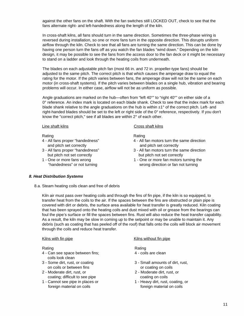
The blades on each adjustable pitch fan (most 66 in. and 72 in. propeller-type fans) should be adjusted to the same pitch. The correct pitch is that which causes the amperage draw to equal the rating for the motor. If the pitch varies between fans, the amperage draw will not be the same on each motor (in cross-shaft systems). If the pitch varies between blades on a single hub, vibration and bearing problems will occur. In either case, airflow will not be as uniform as possible.
Angle graduations are marked on the hub—often from “left 40°” to “right 40°” on either side of a 0° reference. An index mark is located on each blade shank. Check to see that the index mark for each blade shank relative to the angle graduations on the hub is within ±1° of the correct pitch. Left- and right-handed blades should be set to the left or right side of the 0° reference, respectively. If you don't know the "correct pitch," see if all blades are within 2° of each other.
Line shaft kilns Cross shaft kilns
Rating Rating 4 - All fans proper “handedness” 4 - All fan motors turn the same direction and pitch set correctly and pitch set correctly 3 - All fans proper “handedness” 3 - All fan motors turn the same direction but pitch not set correctly but pitch not set correctly 1 - One or more fans wrong 1 - One or more fan motors turning the “handedness” or not turning wrong direction or fan not turning
12
8.b. Steam heating coil baffles present
Coil baffles should be installed around the heating coils. They serve the same function as the baffles around the load except that they direct the air through the heating coils. In a sense, the fan deck is part of the coil baffling. If there is a large gap between the fan deck and the heating coils, the air will pass through this opening, bypassing the coils.
Rating 4 - Baffles direct all air through the heating coils 3 - Most of the space is baffled 2 - Baffling is present but there are openings more than 12 in. wide 1 - Air by-passes heating coils
8.c. Direct-fired, heat distribution system structurally sound and clean
Most direct-fired kilns operate at rather high temperatures. The temperature of the air entering the kiln is commonly 230°F or higher and may be as high as 400°F in some parts of the ductwork. These high temperatures combined with moist air and the frequent cycling from ambient temperature to hot, moist conditions increase the deterioration of many parts of the system. Improperly operated burners can generate sizeable quantities of ash or dust. Frequent cleaning of the risers and other ductwork minimizes the deposition of ash and dust on the surface of the lumber in the kiln. This means brighter lumber, reduced planer wear, and reduced fire risks. Frequent inspection of the ductwork for structural integrity is required for good air transfer as well as for safety reasons.
Rating 4 - Risers cleared of ash and dust weekly, and ductwork inspected quarterly for structural integrity 3 - Risers cleared of ash and dust twice a month, and ductwork inspected semiannually for structural integrity 2 - Risers cleared of ash and dust only when deposits on lumber are excessive, and ductwork inspected annually for structural integrity 1 - Cleaning and inspection not regularly made
9. Vents
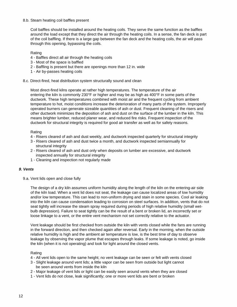
9.a. Vent lids open and close fully
The design of a dry kiln assumes uniform humidity along the length of the kiln on the entering-air side of the kiln load. When a vent lid does not seat, the leakage can cause localized areas of low humidity and/or low temperature. This can lead to non-uniform drying and stain in some species. Cool air leaking into the kiln can cause condensation leading to corrosion on steel surfaces. In addition, vents that do not seat tightly will increase the steam spray required during periods of high relative humidity (small wet- bulb depression). Failure to seat tightly can be the result of a bent or broken lid, an incorrectly set or loose linkage to a vent, or the entire vent mechanism not set correctly relative to the actuator.
Vent leakage should be first checked from outside the kiln with vents closed while the fans are running in the forward direction, and then checked again after reversal. Early in the morning, when the outside relative humidity is high and the ambient air temperature is low, is the best time of day to observe leakage by observing the vapor plume that escapes through leaks. If some leakage is noted, go inside the kiln (when it is not operating) and look for light around the closed vents.
Rating 4 - All vent lids open to the same height; no vent leakage can be seen or felt with vents closed 3 - Slight leakage around vent lids; a little vapor can be seen from outside but light cannot be seen around vents from inside the kiln 2 - Major leakage of vent lids or light can be easily seen around vents when they are closed 1 - Vent lids do not close, leak significantly; one or more vent lids are bent or broken
13
9.b. Vent actuators and linkages operate properly
A mechanical linkage connects the vent actuators to the connecting linkage that opens and closes the vent lids. If the mechanical linkage is worn, it may be incapable of moving the connecting linkage properly. If the fitting on the connecting linkage to the vent lid works loose, the fitting slides on the linkage and does not open the lid. Also, the lid hinges may break, causing the lid to open at an angle across the vent opening rather than straight upward from the opening. When the vents are open, check to see that all lids open to the desired height. Leaking or malfunctioning vents affect both dry-bulb and wet-bulb control, increasing drying degrade.
Rating 4 - Vent actuators and mechanical linkages open vent lids to proper height 3 - Mechanical linkage is worn so vents only partially open or desired vent opening height cannot be achieved for other reasons 2 - One or more vent lids disconnected from connecting linkage 1 - Vents inoperative; vent activators not functioning or linkages disconnected
Yard Area
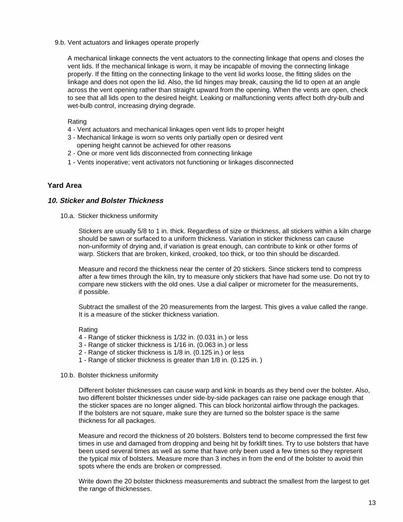
10. Sticker and Bolster Thickness
10.a. Sticker thickness uniformity
Stickers are usually 5/8 to 1 in. thick. Regardless of size or thickness, all stickers within a kiln charge should be sawn or surfaced to a uniform thickness. Variation in sticker thickness can cause non-uniformity of drying and, if variation is great enough, can contribute to kink or other forms of warp. Stickers that are broken, kinked, crooked, too thick, or too thin should be discarded.
Measure and record the thickness near the center of 20 stickers. Since stickers tend to compress after a few times through the kiln, try to measure only stickers that have had some use. Do not try to compare new stickers with the old ones. Use a dial caliper or micrometer for the measurements, if possible.
Subtract the smallest of the 20 measurements from the largest. This gives a value called the range. It is a measure of the sticker thickness variation.
Rating 4 - Range of sticker thickness is 1/32 in. (0.031 in.) or less 3 - Range of sticker thickness is 1/16 in. (0.063 in.) or less 2 - Range of sticker thickness is 1/8 in. (0.125 in.) or less 1 - Range of sticker thickness is greater than 1/8 in. (0.125 in. )
10.b. Bolster thickness uniformity
Different bolster thicknesses can cause warp and kink in boards as they bend over the bolster. Also, two different bolster thicknesses under side-by-side packages can raise one package enough that the sticker spaces are no longer aligned. This can block horizontal airflow through the packages. If the bolsters are not square, make sure they are turned so the bolster space is the same thickness for all packages.
Measure and record the thickness of 20 bolsters. Bolsters tend to become compressed the first few times in use and damaged from dropping and being hit by forklift tines. Try to use bolsters that have been used several times as well as some that have only been used a few times so they represent the typical mix of bolsters. Measure more than 3 inches in from the end of the bolster to avoid thin spots where the ends are broken or compressed.
Write down the 20 bolster thickness measurements and subtract the smallest from the largest to get the range of thicknesses.
14
Rating 4 - Range of bolster thickness is 1/8 in. (0.125 in.) or less 3 - Range of bolster thickness is 1/4 in. (0.250 in.) or less 2 - Range of bolster thickness is 3/8 in. (0.375 in.) or less 1 - Range of bolster thickness is greater than 3/8 in. (0.375 in.)
10.c. Green lumber inventory control
Lumber should be dried as soon as possible after sawing. Tagging or marking packages with the date sawn or stacked will help ensure that the lumber sawn first is dried first. Allowing green lumber to stand in the yard allows it to partially air dry, contributing to MC variability when it is mixed with fresh lumber in the kiln charge. In addition, the green lumber standing in the yard may be more susceptible to stain and other defects.
Rating 4 - Lumber tagging and inventory control system ensures lumber sawn first is dried first 3 - Kiln scheduling is done so most of the time the lumber sawn first is dried first 1 - No inventory control; packages can get “lost” in the yard
Inside an Empty Kiln
11. Inside a Cold Kiln
11.a. Condensation or other water inside kiln
Condensation will occur whenever the temperature is below the dewpoint. Proper kiln design and operation should minimize this. Well-insulated walls reduce condensation as does modulated venting when compared to on-off venting. Water can also enter the kiln through leaks in the roof or around doors. Evidence of condensation and leaks include water spots on the lumber, signs of running water in the kiln, corrosion problems, especially at the base of the walls and around the vents, and pitting of the concrete, especially below the vents and at the base of the columns.
Rating 4 - No evidence of condensation or water in kiln 3 - Some evidence of condensation near walls, at the base of structural members, or under vents, or small water leaks 2 - Much evidence of condensation, corrosion problems, or water leaks 1 - Kiln damage due to condensation or large amounts of water entering kiln
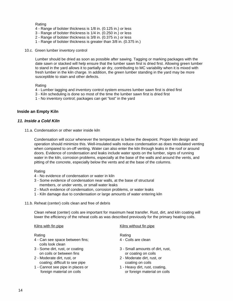
11.b. Reheat (center) coils clean and free of debris
Clean reheat (center) coils are important for maximum heat transfer. Rust, dirt, and kiln coating will lower the efficiency of the reheat coils as was described previously for the primary heating coils.
Kilns with fin pipe Kilns without fin pipe
Rating Rating 4 - Can see space between fins; 4 - Coils are clean coils look clean 3 - Some dirt, rust, or coating 3 - Small amounts of dirt, rust, on coils or between fins or coating on coils 2 - Moderate dirt, rust, or 2 - Moderate dirt, rust, or coating; difficult to see pipe coating on coils 1 - Cannot see pipe in places or 1 - Heavy dirt, rust, coating, foreign material on coils or foreign material on coils
15
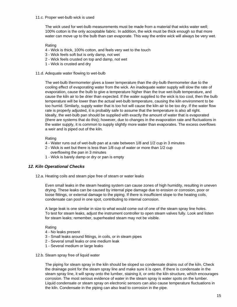
11.c. Proper wet-bulb wick is used
The wick used for wet-bulb measurements must be made from a material that wicks water well; 100% cotton is the only acceptable fabric. In addition, the wick must be thick enough so that more water can move up to the bulb than can evaporate. This way the entire wick will always be very wet.
Rating 4 - Wick is thick, 100% cotton, and feels very wet to the touch 3 - Wick feels soft but is only damp, not wet 2 - Wick feels crusted on top and damp, not wet 1 - Wick is crusted and dry
11.d. Adequate water flowing to wet-bulb
The wet-bulb thermometer gives a lower temperature than the dry-bulb thermometer due to the cooling effect of evaporating water from the wick. An inadequate water supply will slow the rate of evaporation, cause the bulb to give a temperature higher than the true wet-bulb temperature, and cause the kiln air to be drier than expected. If the water supplied to the wick is too cool, then the bulb temperature will be lower than the actual wet-bulb temperature, causing the kiln environment to be too humid. Similarly, supply water that is too hot will cause the kiln air to be too dry. If the water flow rate is properly adjusted, it is probably safe to assume that the temperature is also all right. Ideally, the wet-bulb pan should be supplied with exactly the amount of water that is evaporated (there are systems that do this); however, due to changes in the evaporation rate and fluctuations in the water supply, it is common to supply slightly more water than evaporates. The excess overflows a weir and is piped out of the kiln.
Rating 4 - Water runs out of wet-bulb pan at a rate between 1/8 and 1/2 cup in 3 minutes 2 - Wick is wet but there is less than 1/8 cup of water or more than 1/2 cup overflowing the pan in 3 minutes 1 - Wick is barely damp or dry or pan is empty
12. Kiln Operational Checks
12.a. Heating coils and steam pipe free of steam or water leaks
Even small leaks in the steam heating system can cause zones of high humidity, resulting in uneven drying. These leaks can be caused by internal pipe damage due to erosion or corrosion, poor or loose fittings, or external damage to the piping. If there is insufficient slope to the heating coils, condensate can pool in one spot, contributing to internal corrosion.
A large leak is one similar in size to what would come out of one of the steam spray line holes. To test for steam leaks, adjust the instrument controller to open steam valves fully. Look and listen for steam leaks; remember, superheated steam may not be visible.
Rating 4 - No leaks present 3 - Small leaks around fittings, in coils, or in steam pipes 2 - Several small leaks or one medium leak 1 - Several medium or large leaks
12.b. Steam spray free of liquid water
The piping for steam spray in the kiln should be sloped so condensate drains out of the kiln. Check the drainage point for the steam spray line and make sure it is open. If there is condensate in the steam spray line, it will spray onto the lumber, staining it, or onto the kiln structure, which encourages corrosion. The most serious evidence of water in the steam spray is water spots on the lumber. Liquid condensate or steam spray on electronic sensors can also cause temperature fluctuations in the kiln. Condensate in the piping can also lead to corrosion in the pipe.
16
Rating 4 - No liquid water comes out when steam spray comes on, drain line is open, no water spots on lumber 2 - Improper slope on line or drainage point is blocked 1 - Water spots on lumber that can be traced to the steam spray line or spray line not draining to outside of kiln
12.c. Steam spray uniformly distributed
Just as proper vent operation is necessary to maintain good humidity control along the length of the kiln, steam spray needs to be uniform along the length of the kiln. When the kiln is empty, turn on the spray line and observe each nozzle (drilled hole) in the steam spray line.
Rating 4 - All nozzles appear to produce equal amounts of steam 2 - Steam spray appears not uniform or one nozzle plugged 1 - More than one nozzle plugged
While Preparing Charges and Loading the Kiln
13. Lumber Quality and Package Loading
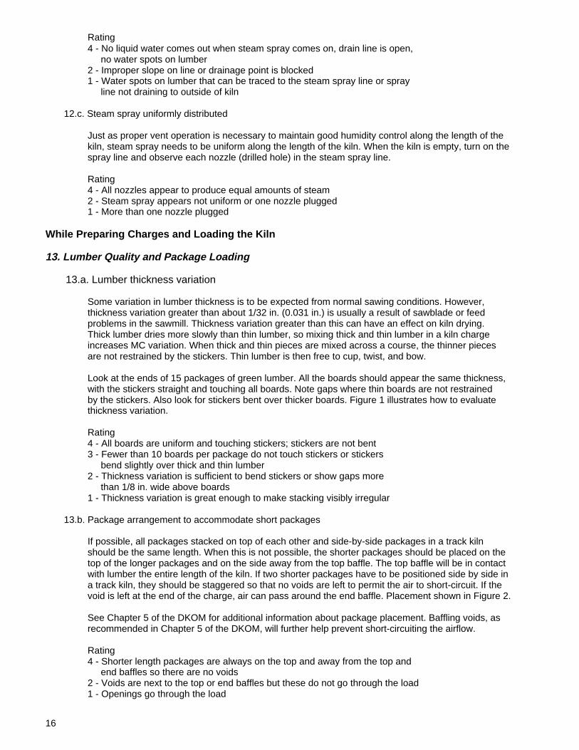
13.a. Lumber thickness variation
Some variation in lumber thickness is to be expected from normal sawing conditions. However, thickness variation greater than about 1/32 in. (0.031 in.) is usually a result of sawblade or feed problems in the sawmill. Thickness variation greater than this can have an effect on kiln drying. Thick lumber dries more slowly than thin lumber, so mixing thick and thin lumber in a kiln charge increases MC variation. When thick and thin pieces are mixed across a course, the thinner pieces are not restrained by the stickers. Thin lumber is then free to cup, twist, and bow.
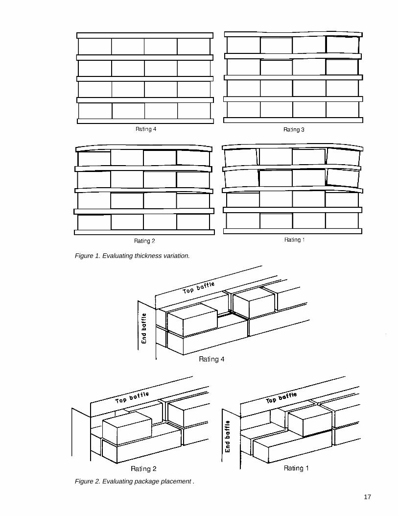
Look at the ends of 15 packages of green lumber. All the boards should appear the same thickness, with the stickers straight and touching all boards. Note gaps where thin boards are not restrained by the stickers. Also look for stickers bent over thicker boards. Figure 1 illustrates how to evaluate thickness variation.
Rating 4 - All boards are uniform and touching stickers; stickers are not bent 3 - Fewer than 10 boards per package do not touch stickers or stickers bend slightly over thick and thin lumber 2 - Thickness variation is sufficient to bend stickers or show gaps more than 1/8 in. wide above boards 1 - Thickness variation is great enough to make stacking visibly irregular
13.b. Package arrangement to accommodate short packages
If possible, all packages stacked on top of each other and side-by-side packages in a track kiln should be the same length. When this is not possible, the shorter packages should be placed on the top of the longer packages and on the side away from the top baffle. The top baffle will be in contact with lumber the entire length of the kiln. If two shorter packages have to be positioned side by side in a track kiln, they should be staggered so that no voids are left to permit the air to short-circuit. If the void is left at the end of the charge, air can pass around the end baffle. Placement shown in Figure 2.
See Chapter 5 of the DKOM for additional information about package placement. Baffling voids, as recommended in Chapter 5 of the DKOM, will further help prevent short-circuiting the airflow.
Rating 4 - Shorter length packages are always on the top and away from the top and end baffles so there are no voids 2 - Voids are next to the top or end baffles but these do not go through the load 1 - Openings go through the load
17
Figure 1. Evaluating thickness variation.
Figure 2. Evaluating package placement .
18
14. Package Support
14.a. Bottom load support uniformity
The load supports under the bottom packages should be of equal height to prevent warp or kink. This means all kiln trucks in track kilns or load supports in package kilns should be the same height. Preferably, a load support should be placed under each column of stickers. If this is not possible, the load supports should not be more than 4 ft apart. In package kilns, bottom load supports of unequal height under adjacent packages may raise one package enough to block horizontal airflow through the packages.
Track kilns Package kilns
Rating Rating 4 - All kiln trucks equal height 4 - All load supports equal height 3 - One kiln truck more than 3 - One or 2 load supports more than 1/4 in. higher or lower than others 1/4 in. higher or lower than others 2 - Two or 3 kiln trucks more 2 - Four to 6 load supports more than 1/4 in. higher or 1/4 in. higher or lower than lower than others others 1 - Four or more kiln trucks 1 - More than 6 load supports more than 1/4 in. higher or 1/4 in. higher or lower than lower than others others
14.b. Rails (track-loaded kilns)
Rails need to be supported by a level, immobile foundation. When the rails are uneven, the kiln trucks are not all in the same plane. This, in turn, can cause lumber to bow or twist. Watch the rails as the loaded trucks are rolled across them. If they deflect, they may not be securely fastened to the foundation or the foundation may have weakened or settled. Be careful while you are watching the trucks move in case the lumber shifts.
Rating 4 - All rails level and well supported with no sign of deflection 3 - Rails settle or move slightly in one or two places 2 - Dips in rails or more than 1/2 in. deflection when loaded 1 - Rails visibly out of level or have a large amount of deflection
During Kiln Startup and Operation
15. During Kiln Startup
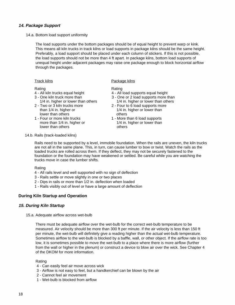
15.a. Adequate airflow across wet-bulb
There must be adequate airflow over the wet-bulb for the correct wet-bulb temperature to be measured. Air velocity should be more than 300 ft per minute. If the air velocity is less than 150 ft per minute, the wet-bulb will definitely give a reading higher than the actual wet-bulb temperature. Sometimes airflow to the wet-bulb is blocked by a baffle, wall, or other object. If the airflow rate is too low, it is sometimes possible to move the wet-bulb to a place where there is more airflow (further from the wall or higher in the plenum) or construct a device to blow air over the wick. See Chapter 4 of the DKOM for more information.
Rating 4 - Can easily feel air move across wick 3 - Airflow is not easy to feel, but a handkerchief can be blown by the air 2 - Cannot feel air movement 1 - Wet-bulb is blocked from airflow
19
15.b. Confirm that traps are functioning
Checking traps regularly is part of the standard kiln operating procedures. When the kiln is starting up, check the traps to confirm that they are working properly and are capable of handling the startup load. For example, a properly sized trap will discharge condensate intermittently. A continuous discharge of steam indicates a problem. Large amounts of condensate behind the trap may indicate a problem. Chapter 2 of the DKOM contains more information on traps.
Rating 4 - All traps are working 3 - Traps do not quite handle condensate during startup 2 - Traps are very undersized for startup and hold back a large amount of condensate 1 - One or more traps are not working
16. While Kiln Is Operating
16.a. Doors, walls, and roof free of leaks
Leaks in the kiln structure cause areas of low humidity and/or low temperature. This can lead to non-uniform drying and possible stain problems in some species. In addition, leaks are evidence of a structure that is in need of repair. Cool air leaking into the kiln can cause condensation leading to corrosion problems. During parts of the cycle in which the steam spray is used, leaks in the kiln structure increase the steam required.
Leaks show up as water vapor leaving the kiln on the entering-air side of the load. On the other side, air is being drawn into the kiln so the leaks are not visible. Check for leakage with the fans running first in one direction, then the other. Carefully check doors for leaks—door leaks are the most common type of leak. A slight leak means that vapor is visible or can be felt while the kiln is operating, but no daylight can be seen to identify the opening from inside the kiln. Large leaks are identified by large amount of vapor and by daylight being visible from inside the kiln.
Rating 4 - No leaks are visible or only slight leaks around rails 3 - Slight leaks around doors or other small leaks 2 - Large leaks 1 - Holes visible in the kiln structure
16.b. Confirm fan reversal by feeling airflow direction
The control charts gave an indication that fan reversals were occurring. While the kiln is running, confirm that the fans actually reverse by feeling the airflow direction before and after fan reversal. Use caution with high-temperature schedules.
Rating 4 - Airflow actually reverses 1 - Airflow does not actually reverse when timer or control chart indicates it should
After Drying Is Completed
17. Before Unloading Kiln
17.a. Pile height uniform
All packages in a kiln charge should be of a uniform height. This allows the top baffles to continuously contact the lumber pile along the entire length of the charge. Low packages leave space under the baffle for air to bypass the load. If low packages are in the charge, they should be on the side away from the top baffle. After the lumber has shrunk in drying, check for gaps under the top baffle.
20
Rating 4 - All pile heights are the same 3 - Pile height varies only on the side away from the top baffle 2 - Pile height varies up to 6 in. on the top baffle side 1 - Pile height varies by more than 6 in. on the top baffle side
17.b. Baffles used properly
Baffles in the kiln direct the air through the courses of lumber rather than letting it go around the ends, over the top, or under the load. Overhead, end, and floor baffles should always be used on every load. Not doing so almost guarantees unevenly dried lumber, requires extra time in the kiln, and wastes energy.
Baffles should be placed flush against all sides of the load and well secured, so they are not blown out of position during drying. As the lumber shrinks in drying, gaps may be left between the baffles and the load, which also allows air to bypass the sticker openings. If this occurs, repositioning or enlarging the baffles may be necessary. When you open the kiln after drying, check the baffles to verify that they remained in place and were tight against the load throughout the cycle.
Rating 4 - Baffles are placed flush against the top, bottom, and ends of the load and were held securely during drying 3 - No spaces greater than 6 in. between the baffles and the load and the baffles were held securely 2 - No spaces greater than 12 in. between the baffles and the load and the baffles were held securely 1 - Baffles are missing, bent, or openings are greater than 12 in. between the baffles and the load; any baffles were unsecured
17.c. Adequate plenum width
Adequate width of the plenum chamber is necessary for uniform airflow through all the sticker spaces. If the plenum chamber is too narrow, airflow will drop off at the top of the load. The plenum width should equal the sum of the sticker and bolster openings.
In track kilns, if the door opening is significantly wider than the kiln cars, there is a temptation to use wider kiln cars. This reduces the plenum chamber width while increasing the length of airflow through the sticker openings. The combined effect can lead to uneven airflow, and thus uneven drying. Similarly, an adequate plenum must be maintained in package kilns. Chapter 2 of the DKOM contains more information about the plenum chamber.
Rating 4 - Plenum width equals the sum of the sticker and bolster openings 3 - Plenum width is between 3/4 and 1-1/4 times the sum of the sticker and bolster openings 2 - Plenum width is between 1/2 and 1-1/2 times the sum of the sticker and bolster openings 1 - Plenum width is less than 1/2 or more than 1-1/2 times the sum of the sticker and bolster openings
18. Before Piles Are Broken Down
18.a. Spot check MC with a moisture meter.
After the lumber has cooled, spot check the MC with a hand-held moisture meter. Check 10 boards at eight locations. In track kilns, check four columns of boards on each side of the track. Of the four, check two of the columns of boards near each end of the kiln and the other two half way to the center of the kiln. In package kilns, take four sets of board moisture measurements in each row of packages. Be sure to sample equally from the top, middle, and bottom packages at each location. You may need a ladder to reach the top packages.
21
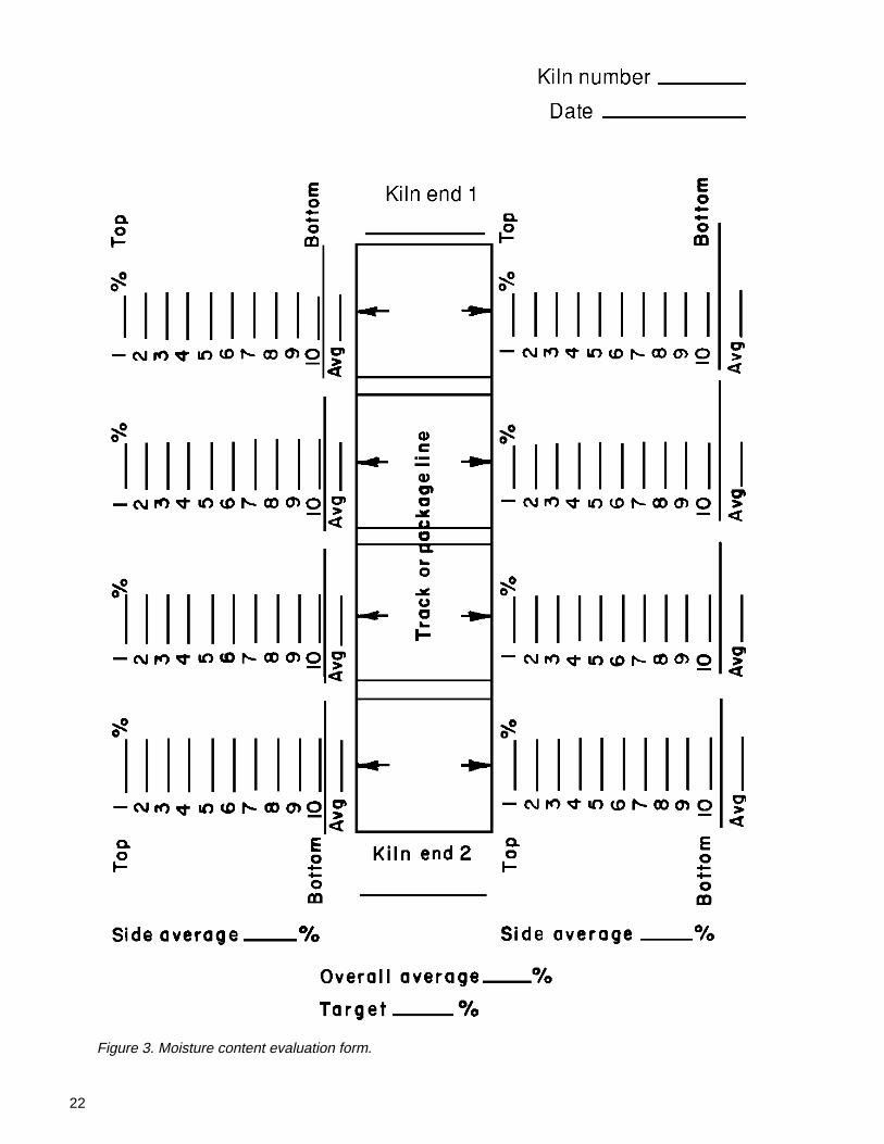
Select the boards a few courses from the top, at the center, and a few courses from the bottom of each package. If you are using a pin-type meter, be sure to use insulated pins that preferably are long enough to penetrate at least 1-1/2 in. Carefully center the pins on the edge surface of the board so they are parallel to its length. Drive them in straight and almost all the way. Be at least 3 ft from the end of a board. Be sure to make the appropriate species and temperature corrections on the readings. Record the readings so you will know where each reading came from. A suggested form to record this information is shown in Figure 3.
Calculate the average of the readings for each track. Also calculate an average for each end of the kiln, each row of packages (top and bottom), and an overall average for the kiln. When comparing the readings and averages to the target, use whatever allowance (if any) you normally use to account for measuring only at the edge of the load.
If the average values do not agree closely with each other or you see patterns of wet or overdry areas, it indicates something in the kiln is causing non-uniform drying. Further checking of the heating, air, and control systems is desirable. If individual readings differ greatly from target readings (using the recommendations in the rating key), a longer, slower drying schedule or an equalizing period may be needed to obtain more uniform final MCs.
Typically, products that are dried to MCs below 13% target are of higher value, and variations in MC are more critical. Therefore, there are two grading scales, one for target MC below 13% and one for target above 13%.
Target MC below 13% Target MC above 13% or MC variation is critical or MC variation is less critical
Rating Rating 4 - All individual board readings 4 - All individual board readings within 3% MC of target and within 5% MC of target and all averages within 2% MC of all averages within 3% MC target of target 3 - All individual board readings 3 - All individual board readings within 5% MC of target and within 8% MC of target and all averages within 3% MC all averages within 4% MC of target of target 2 - More than 10 individual 2 - More than 10 individual readings differ from target readings differ from target by more than 6% but all by more than 8% but all averages are within 4% of averages are within 5% of target target 1 - More than 20 individual 1 - More than 20 individual readings differ from target readings differ from target by more than 6% or any by more than 8% or any average is more than 4% average is more than 5% away from target away from target
18.b. Dry end covered
Once the lumber has been dried, its quality should be protected from degrade due to rain and snow.
Rating 4 - Dry end storage is covered with a protective shed 3 - Covered shed allows wind-driven rain to wet the lumber 2 - Shed leaks 1 - No protection from weather
22
Figure 3. Moisture content evaluation form.
23
Evaluate Stacking and Its Effect on Drying Quality
Proper stacking is important for preventing warp and ensuring proper kiln loading and adequate airflowthrough the kiln charge. Usually the stacking operation is remote from the kilns and the kiln operator; however,it is vital that the kiln operator pay close attention to how well the lumber is stacked and to provide feedback tothe sawmill when a problem arises. By evaluating stickering and stacking practices after drying, you can seehow they affected drying quality. Chapter 5 of the DKOM contains additional information about stickeringand stacking.
19. Sticker Placement
19.a. Sticker alignment
Stickers serve two main purposes. First, they separate the courses of lumber so that air can move through the stack to dry the lumber. Second, they distribute the weight of the lumber vertically from top to bottom—through the stickers and bolsters down to the kiln truck or load supports. Stickers out of alignment, on edge, or missing from their position can be costly to lumber quality (grade) by causing kink, twist, ski-tipped ends, and other forms of warp.
Ideally, all stickers in a column are vertically in line. In practice, however, the stickers are not perfectly positioned and may move after being placed by the stacker. For proper alignment, a sticker should at least overlap the ones above and below.
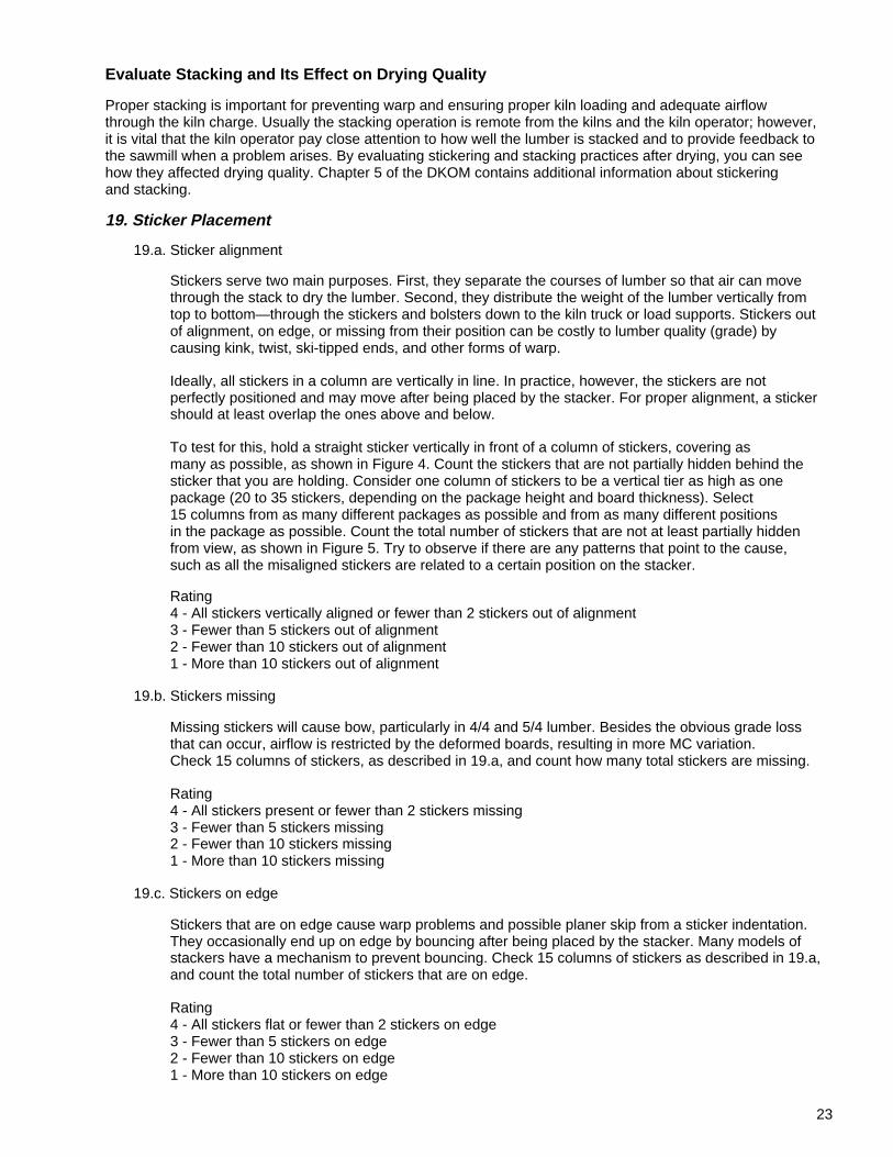
To test for this, hold a straight sticker vertically in front of a column of stickers, covering as many as possible, as shown in Figure 4. Count the stickers that are not partially hidden behind the sticker that you are holding. Consider one column of stickers to be a vertical tier as high as one package (20 to 35 stickers, depending on the package height and board thickness). Select 15 columns from as many different packages as possible and from as many different positions in the package as possible. Count the total number of stickers that are not at least partially hidden from view, as shown in Figure 5. Try to observe if there are any patterns that point to the cause, such as all the misaligned stickers are related to a certain position on the stacker.
Rating 4 - All stickers vertically aligned or fewer than 2 stickers out of alignment 3 - Fewer than 5 stickers out of alignment 2 - Fewer than 10 stickers out of alignment 1 - More than 10 stickers out of alignment
19.b. Stickers missing
Missing stickers will cause bow, particularly in 4/4 and 5/4 lumber. Besides the obvious grade loss that can occur, airflow is restricted by the deformed boards, resulting in more MC variation. Check 15 columns of stickers, as described in 19.a, and count how many total stickers are missing.
Rating 4 - All stickers present or fewer than 2 stickers missing 3 - Fewer than 5 stickers missing 2 - Fewer than 10 stickers missing 1 - More than 10 stickers missing
19.c. Stickers on edge
Stickers that are on edge cause warp problems and possible planer skip from a sticker indentation. They occasionally end up on edge by bouncing after being placed by the stacker. Many models of stackers have a mechanism to prevent bouncing. Check 15 columns of stickers as described in 19.a, and count the total number of stickers that are on edge.
Rating 4 - All stickers flat or fewer than 2 stickers on edge 3 - Fewer than 5 stickers on edge 2 - Fewer than 10 stickers on edge 1 - More than 10 stickers on edge
24
Figure 4. Check sticker placement by holding a stickervertically in front of sticker column.
19.d. Double stickers (one on top of the other)
Double stickers also cause kink and warp in the lumber. Check 15 columns of stickers as described in 19.a and count how many times double stickers occur.
Rating 4 - No double stickers or only one set 3 - Fewer than 3 sets of double stickers 2 - Fewer than 5 sets of double stickers 1 - More than 5 sets of double stickers
19.e. Sticker placement at ends of packages
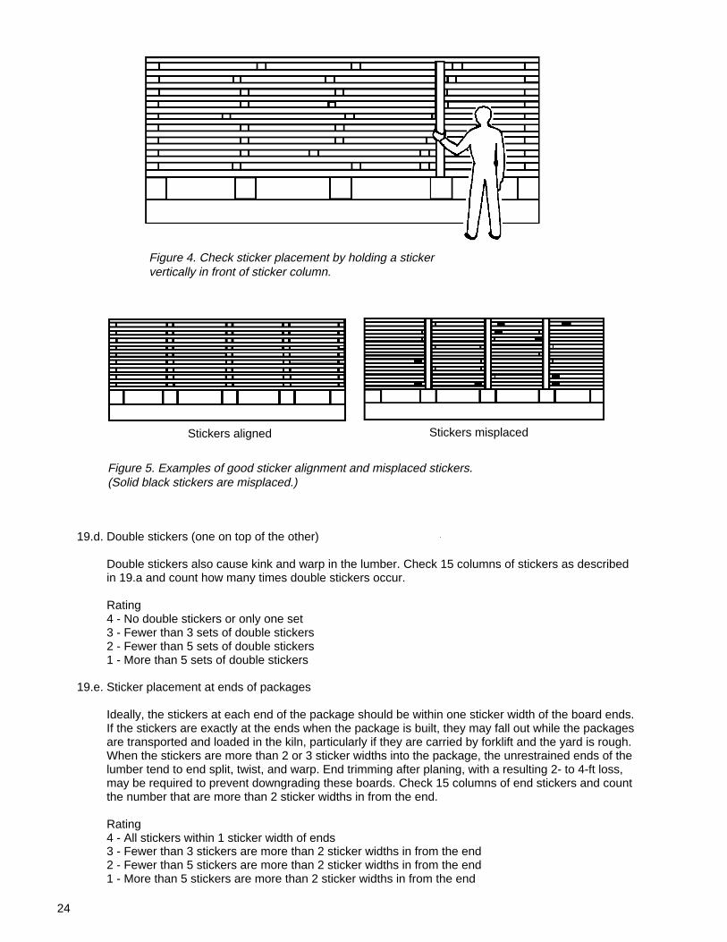
Ideally, the stickers at each end of the package should be within one sticker width of the board ends. If the stickers are exactly at the ends when the package is built, they may fall out while the packages are transported and loaded in the kiln, particularly if they are carried by forklift and the yard is rough. When the stickers are more than 2 or 3 sticker widths into the package, the unrestrained ends of the lumber tend to end split, twist, and warp. End trimming after planing, with a resulting 2- to 4-ft loss, may be required to prevent downgrading these boards. Check 15 columns of end stickers and count the number that are more than 2 sticker widths in from the end.
Rating 4 - All stickers within 1 sticker width of ends 3 - Fewer than 3 stickers are more than 2 sticker widths in from the end 2 - Fewer than 5 stickers are more than 2 sticker widths in from the end 1 - More than 5 stickers are more than 2 sticker widths in from the end
Figure 5. Examples of good sticker alignment and misplaced stickers.(Solid black stickers are misplaced.)
Stickers aligned Stickers misplaced
25
20. Board Placement in Packages
20.a. Packages are square at both ends
Both ends of the package should be even-ended or “squared-up.” In track kilns, individual board ends extending more than about 3 in. beyond the package end can cause problems loading the kiln. These include difficulty placing packages on the trucks, pushing boards in the next package off the end stickers when pushing the trucks into the kiln, inability to push cribs together, and damaging board ends. At the extreme, the kiln doors may not close, and it is necessary to remove overhanging ends with a chain saw. In package kilns, package loading is difficult and the spaces between packages result in poor airflow patterns. Check both ends of at least 15 packages for overhanging boards and boards that do not reach the end sticker.
Rating 4 - All boards in all packages reach and are supported by the end sticker; ends of package are vertical 3 - Fewer than 5 boards do not reach the end sticker or extend 3 to 6 in. beyond it 2 - Fewer than 10 boards do not reach the end sticker or extend 6 to 12 in. beyond it 1 - More than 10 boards do not reach the end sticker or extend more than 12 in. beyond it
20.b. Sides of packages even
The sides of the packages should be even from top to bottom on the side facing the plenum and preferably on both sides. This gives all sticker openings equal opportunity for airflow. When courses are staggered more than 3 in. within the package, some sticker openings get more airflow than others as illustrated in Figure 6. If one side of the package is even and the other “ragged,” place the even side toward the plenum. Check the plenum side of at least 15 packages.
Rating 4 - All sides of packages toward plenum are even 3 - Fewer than 10 courses on plenum side are not even 2 - Fewer than 30 courses on plenum side are not even 1 - More than 30 courses on plenum side are not even
20.c. Overlapped boards in package
When building the packages either mechanically or by hand, boards may become overlapped. This overlap blocks airflow through the sticker space, causes the overlapped board to cup or possibly split, and bends or even breaks the stickers. The high spot caused by the double board thickness prevents even stacking and makes the entire package unstable. Check the ends of at least 15 packages.
Rating 4 - No overlapped boards can be seen 3 - Fewer than 3 sets of boards overlap 2 - Fewer than 5 sets of boards overlap 1 - More than 5 sets of boards overlap
21. Package and Bolster Placement
21.a. Bolster (bunk) placement
Bolsters should be placed in vertical alignment with every column of stickers. This assures that the weight of lumber is transferred down through the load without causing bow or sticker kink.
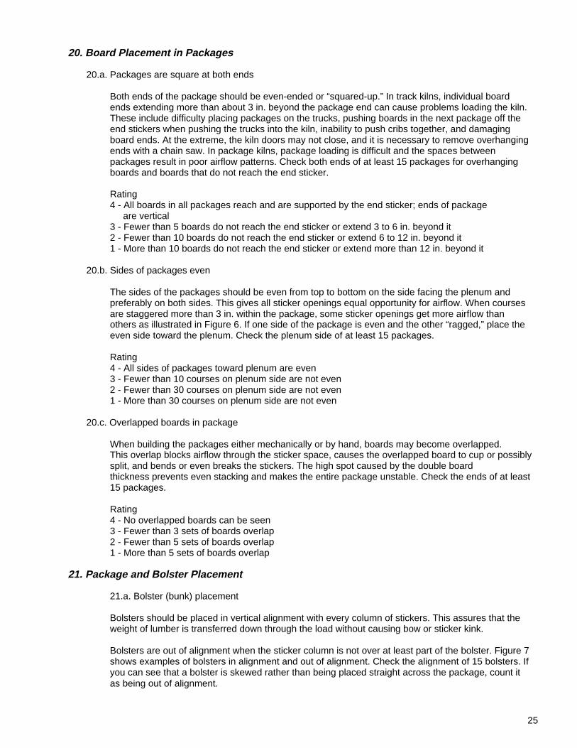
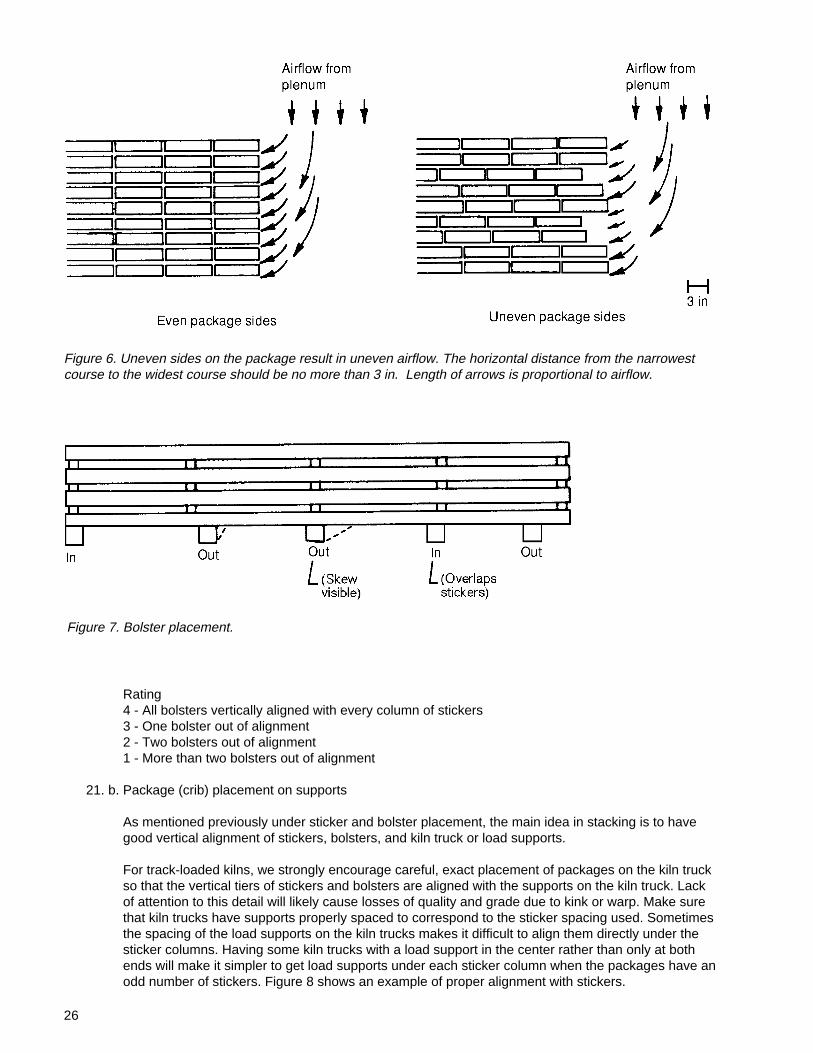
Bolsters are out of alignment when the sticker column is not over at least part of the bolster. Figure 7 shows examples of bolsters in alignment and out of alignment. Check the alignment of 15 bolsters. If you can see that a bolster is skewed rather than being placed straight across the package, count it as being out of alignment.
26
Figure 6. Uneven sides on the package result in uneven airflow. The horizontal distance from the narrowestcourse to the widest course should be no more than 3 in. Length of arrows is proportional to airflow.
Rating 4 - All bolsters vertically aligned with every column of stickers 3 - One bolster out of alignment 2 - Two bolsters out of alignment 1 - More than two bolsters out of alignment
21. b. Package (crib) placement on supports
As mentioned previously under sticker and bolster placement, the main idea in stacking is to have good vertical alignment of stickers, bolsters, and kiln truck or load supports.
For track-loaded kilns, we strongly encourage careful, exact placement of packages on the kiln truck so that the vertical tiers of stickers and bolsters are aligned with the supports on the kiln truck. Lack of attention to this detail will likely cause losses of quality and grade due to kink or warp. Make sure that kiln trucks have supports properly spaced to correspond to the sticker spacing used. Sometimes the spacing of the load supports on the kiln trucks makes it difficult to align them directly under the sticker columns. Having some kiln trucks with a load support in the center rather than only at both ends will make it simpler to get load supports under each sticker column when the packages have an odd number of stickers. Figure 8 shows an example of proper alignment with stickers.
Figure 7. Bolster placement.
27
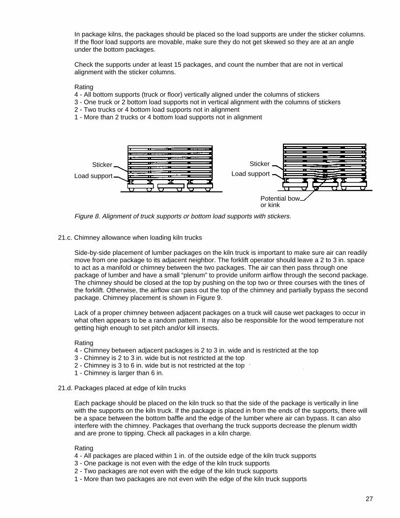
In package kilns, the packages should be placed so the load supports are under the sticker columns. If the floor load supports are movable, make sure they do not get skewed so they are at an angle under the bottom packages.
Check the supports under at least 15 packages, and count the number that are not in vertical alignment with the sticker columns.
Rating 4 - All bottom supports (truck or floor) vertically aligned under the columns of stickers 3 - One truck or 2 bottom load supports not in vertical alignment with the columns of stickers 2 - Two trucks or 4 bottom load supports not in alignment 1 - More than 2 trucks or 4 bottom load supports not in alignment
21.c. Chimney allowance when loading kiln trucks
Side-by-side placement of lumber packages on the kiln truck is important to make sure air can readily move from one package to its adjacent neighbor. The forklift operator should leave a 2 to 3 in. space to act as a manifold or chimney between the two packages. The air can then pass through one package of lumber and have a small “plenum” to provide uniform airflow through the second package. The chimney should be closed at the top by pushing on the top two or three courses with the tines of the forklift. Otherwise, the airflow can pass out the top of the chimney and partially bypass the second package. Chimney placement is shown in Figure 9.
Lack of a proper chimney between adjacent packages on a truck will cause wet packages to occur in what often appears to be a random pattern. It may also be responsible for the wood temperature not getting high enough to set pitch and/or kill insects.
Rating 4 - Chimney between adjacent packages is 2 to 3 in. wide and is restricted at the top 3 - Chimney is 2 to 3 in. wide but is not restricted at the top 2 - Chimney is 3 to 6 in. wide but is not restricted at the top 1 - Chimney is larger than 6 in.
21.d. Packages placed at edge of kiln trucks
Each package should be placed on the kiln truck so that the side of the package is vertically in line with the supports on the kiln truck. If the package is placed in from the ends of the supports, there will be a space between the bottom baffle and the edge of the lumber where air can bypass. It can also interfere with the chimney. Packages that overhang the truck supports decrease the plenum width and are prone to tipping. Check all packages in a kiln charge.
Rating 4 - All packages are placed within 1 in. of the outside edge of the kiln truck supports 3 - One package is not even with the edge of the kiln truck supports 2 - Two packages are not even with the edge of the kiln truck supports 1 - More than two packages are not even with the edge of the kiln truck supports
Figure 8. Alignment of truck supports or bottom load supports with stickers.
Load support
Sticker
Potential bowor kink
Sticker
Load support
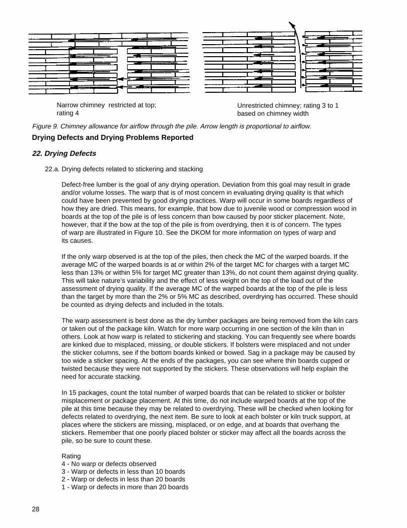
28
Narrow chimney restricted at top;rating 4
Unrestricted chimney; rating 3 to 1based on chimney width
Drying Defects and Drying Problems Reported
22. Drying Defects
22.a. Drying defects related to stickering and stacking
Defect-free lumber is the goal of any drying operation. Deviation from this goal may result in grade and/or volume losses. The warp that is of most concern in evaluating drying quality is that which could have been prevented by good drying practices. Warp will occur in some boards regardless of how they are dried. This means, for example, that bow due to juvenile wood or compression wood in boards at the top of the pile is of less concern than bow caused by poor sticker placement. Note, however, that if the bow at the top of the pile is from overdrying, then it is of concern. The types of warp are illustrated in Figure 10. See the DKOM for more information on types of warp and its causes.
If the only warp observed is at the top of the piles, then check the MC of the warped boards. If the average MC of the warped boards is at or within 2% of the target MC for charges with a target MC less than 13% or within 5% for target MC greater than 13%, do not count them against drying quality. This will take nature’s variability and the effect of less weight on the top of the load out of the assessment of drying quality. If the average MC of the warped boards at the top of the pile is less than the target by more than the 2% or 5% MC as described, overdrying has occurred. These should be counted as drying defects and included in the totals.
The warp assessment is best done as the dry lumber packages are being removed from the kiln cars or taken out of the package kiln. Watch for more warp occurring in one section of the kiln than in others. Look at how warp is related to stickering and stacking. You can frequently see where boards are kinked due to misplaced, missing, or double stickers. If bolsters were misplaced and not under the sticker columns, see if the bottom boards kinked or bowed. Sag in a package may be caused by too wide a sticker spacing. At the ends of the packages, you can see where thin boards cupped or twisted because they were not supported by the stickers. These observations will help explain the need for accurate stacking.
In 15 packages, count the total number of warped boards that can be related to sticker or bolster misplacement or package placement. At this time, do not include warped boards at the top of the pile at this time because they may be related to overdrying. These will be checked when looking for defects related to overdrying, the next item. Be sure to look at each bolster or kiln truck support, at places where the stickers are missing, misplaced, or on edge, and at boards that overhang the stickers. Remember that one poorly placed bolster or sticker may affect all the boards across the pile, so be sure to count these.
Rating 4 - No warp or defects observed 3 - Warp or defects in less than 10 boards 2 - Warp or defects in less than 20 boards 1 - Warp or defects in more than 20 boards
Figure 9. Chimney allowance for airflow through the pile. Arrow length is proportional to airflow.
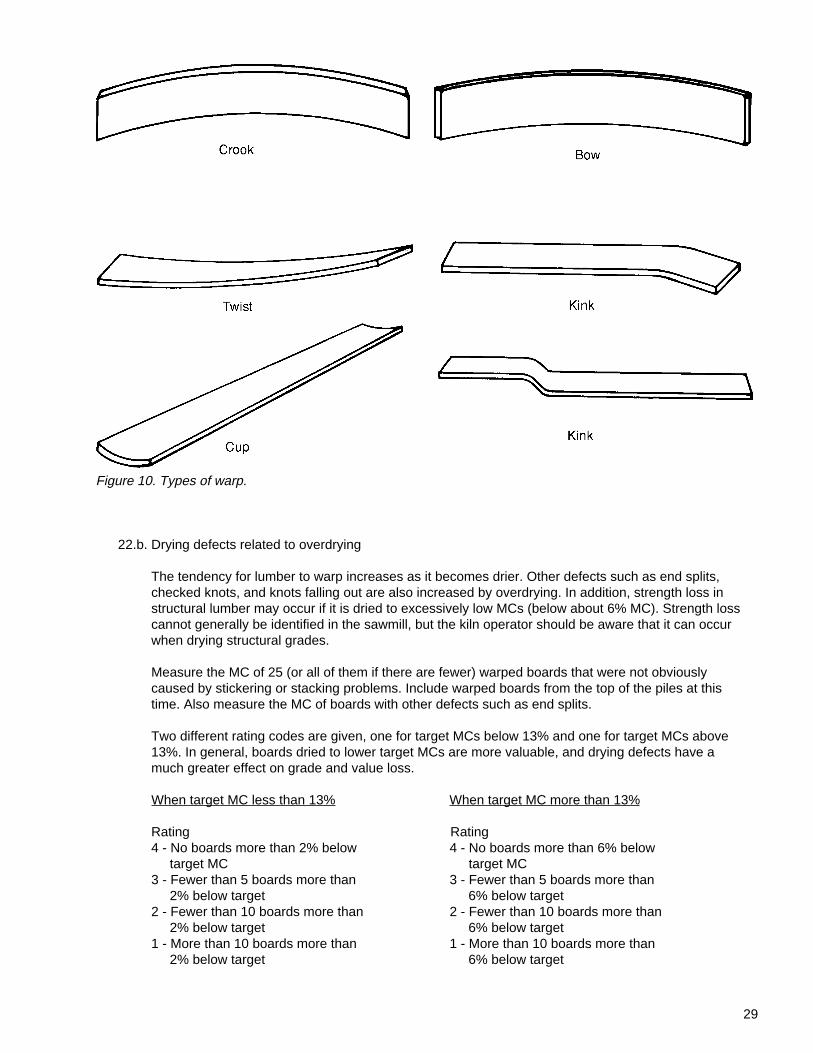
29
Figure 10. Types of warp.
22.b. Drying defects related to overdrying
The tendency for lumber to warp increases as it becomes drier. Other defects such as end splits, checked knots, and knots falling out are also increased by overdrying. In addition, strength loss in structural lumber may occur if it is dried to excessively low MCs (below about 6% MC). Strength loss cannot generally be identified in the sawmill, but the kiln operator should be aware that it can occur when drying structural grades.
Measure the MC of 25 (or all of them if there are fewer) warped boards that were not obviously caused by stickering or stacking problems. Include warped boards from the top of the piles at this time. Also measure the MC of boards with other defects such as end splits.
Two different rating codes are given, one for target MCs below 13% and one for target MCs above 13%. In general, boards dried to lower target MCs are more valuable, and drying defects have a much greater effect on grade and value loss.
When target MC less than 13% When target MC more than 13%
Rating Rating 4 - No boards more than 2% below 4 - No boards more than 6% below target MC target MC 3 - Fewer than 5 boards more than 3 - Fewer than 5 boards more than 2% below target 6% below target 2 - Fewer than 10 boards more than 2 - Fewer than 10 boards more than 2% below target 6% below target 1 - More than 10 boards more than 1 - More than 10 boards more than 2% below target 6% below target
30
22.c. End checking or end splits visible in stickered lumber (Exclude ring failure, ring and wind shake)
End checking and end splits can start in log ends or as soon as freshly exposed ends are generated during lumber manufacture. End checks and splits can occur while green lumber stands in the open yard, waiting for the kiln. Another cause is not placing stickers close enough to the board ends. Check the ends of 15 packages and count the number of end checks and splits deeper than 2 in.
Rating 4 - No end checks or end splits visible 3 - End checks or end splits deeper than 2 in. in less than 10 boards 2 - End checks or end splits deeper than 2 in. in less than 20 boards 1 - End checks or end splits deeper than 2 in. in more than 20 boards
22.d. Stain related to drying conditions
Two common forms of stain are blue stain and brown stain. Blue stain is caused by a fungus and gives a gray-blue cast to the sapwood. It frequently starts in the log due to damage or excessively long storage periods in the woods or in the yard. Brown stain is caused by either enzymatic action on certain complex compounds in the wood or naturally occurring compounds in the sapwood-heartwood transition zone. It appears as brown streaks or as an overall brown discoloration. Poor lumber handling and kiln schedules can increase stains. The causes of stain and how to control them are discussed further in Chapter 8 of the DKOM.
The evaluation of stain should be done as the lumber is being unstacked. Watch at least two packages (from different parts of the kiln) as they are unstacked and look for stain. This evaluation might have to be done after the planer, if the stain is too hard to see at the unstacker.
Rating 4 - No stain is visible 3 - No more than 10 boards are stained 2 - No more than 20 boards are stained 1 - More than 20 boards are stained
23. Lumber Moisture Content and Degrade Problems Reported
23.a. Planer operators and graders report of problems
The planer operators and graders are good sources from which to learn about drying quality problems. Conditions that cause machining problems or degrade are often not visible in the piled lumber when it is taken out of the dry kiln. The graders see the effects of warp, splits, checks, stain, and other defects on lumber grade.
Lumber final MC affects planing quality. Planing lumber that is too wet often results in fuzzy grain. If the lumber is overdried, planing can tear the grain, especially cross-grain around knots, and knots may check or fall out. Overdried lumber is prone to roller splitting, especially if it cupped from lack of sticker restraint.
Some of what appears to be drying degrade may be due to other causes. For example, some warp may be unavoidable because of compression wood, juvenile wood, or cross-grain around knots. Splits may be a result of mechanical damage in logging or sawing. Checking sticker alignment and MC of warped boards, as previously described, will help identify the cause of warping. Looking at a sample of green boards can verify if mechanical damage is one source of splits.
31
Rating 4 - Few planing or degrade problems are reported 3 - Degrade or MC related planing problems affect less than 5% of production 2 - Degrade or MC related planing problems affect less than 10% of production 1 - Degrade or MC related planing problems affect more than 10% of production
23.b. Moisture content reports from planer
Many mills measure MC at the planer or grading station, either manually or with in-line moisture meters. The kiln operator should be aware of the lumber MC distribution as a check on kiln schedules.
Rating 4 - All lumber within the desired limits 3 - Less than 5% of production is outside desired limits
2 - Less than 10% of production is outside desired limits 1 - More than 10% of production is outside desired limits
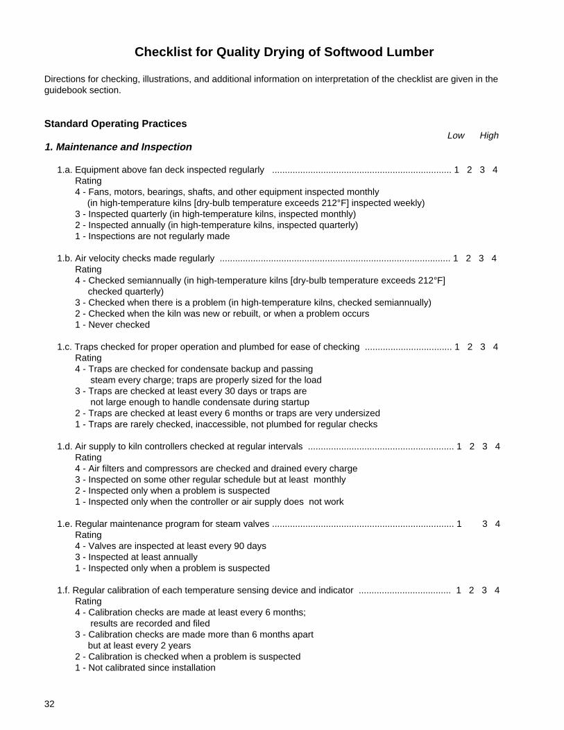
32
Checklist for Quality Drying of Softwood Lumber
Directions for checking, illustrations, and additional information on interpretation of the checklist are given in theguidebook section.
Standard Operating Practices Low High1. Maintenance and Inspection
1.a. Equipment above fan deck inspected regularly ...................................................................... 1 2 3 4 Rating 4 - Fans, motors, bearings, shafts, and other equipment inspected monthly
(in high-temperature kilns [dry-bulb temperature exceeds 212°F] inspected weekly) 3 - Inspected quarterly (in high-temperature kilns, inspected monthly) 2 - Inspected annually (in high-temperature kilns, inspected quarterly) 1 - Inspections are not regularly made
1.b. Air velocity checks made regularly .......................................................................................... 1 2 3 4 Rating 4 - Checked semiannually (in high-temperature kilns [dry-bulb temperature exceeds 212°F] checked quarterly) 3 - Checked when there is a problem (in high-temperature kilns, checked semiannually) 2 - Checked when the kiln was new or rebuilt, or when a problem occurs 1 - Never checked
1.c. Traps checked for proper operation and plumbed for ease of checking .................................. 1 2 3 4 Rating 4 - Traps are checked for condensate backup and passing steam every charge; traps are properly sized for the load 3 - Traps are checked at least every 30 days or traps are not large enough to handle condensate during startup 2 - Traps are checked at least every 6 months or traps are very undersized 1 - Traps are rarely checked, inaccessible, not plumbed for regular checks
1.d. Air supply to kiln controllers checked at regular intervals ......................................................... 1 2 3 4 Rating 4 - Air filters and compressors are checked and drained every charge 3 - Inspected on some other regular schedule but at least monthly 2 - Inspected only when a problem is suspected 1 - Inspected only when the controller or air supply does not work
1.e. Regular maintenance program for steam valves ....................................................................... 1 3 4 Rating 4 - Valves are inspected at least every 90 days 3 - Inspected at least annually 1 - Inspected only when a problem is suspected
1.f. Regular calibration of each temperature sensing device and indicator .................................... 1 2 3 4 Rating 4 - Calibration checks are made at least every 6 months; results are recorded and filed 3 - Calibration checks are made more than 6 months apart but at least every 2 years 2 - Calibration is checked when a problem is suspected 1 - Not calibrated since installation
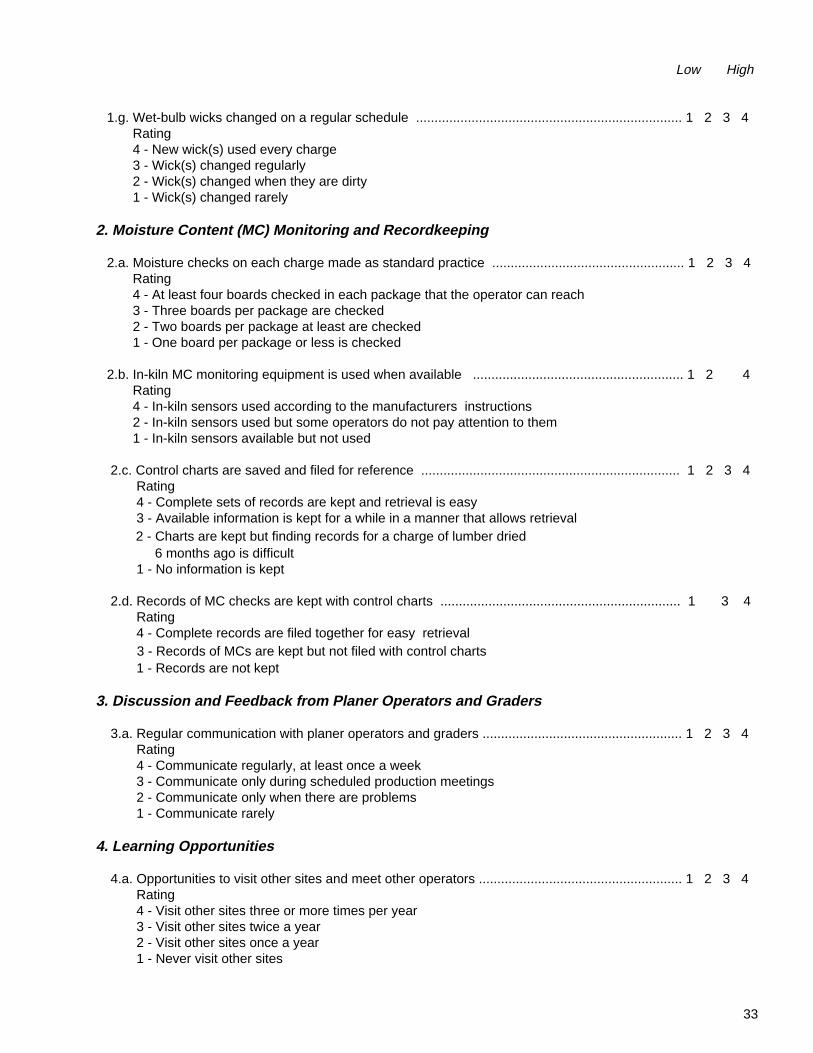
33
Low High
1.g. Wet-bulb wicks changed on a regular schedule ........................................................................ 1 2 3 4 Rating 4 - New wick(s) used every charge 3 - Wick(s) changed regularly 2 - Wick(s) changed when they are dirty 1 - Wick(s) changed rarely
2. Moisture Content (MC) Monitoring and Recordkeeping
2.a. Moisture checks on each charge made as standard practice .................................................... 1 2 3 4 Rating 4 - At least four boards checked in each package that the operator can reach 3 - Three boards per package are checked 2 - Two boards per package at least are checked 1 - One board per package or less is checked
2.b. In-kiln MC monitoring equipment is used when available ......................................................... 1 2 4 Rating 4 - In-kiln sensors used according to the manufacturers instructions 2 - In-kiln sensors used but some operators do not pay attention to them 1 - In-kiln sensors available but not used
2.c. Control charts are saved and filed for reference ...................................................................... 1 2 3 4 Rating 4 - Complete sets of records are kept and retrieval is easy 3 - Available information is kept for a while in a manner that allows retrieval
2 - Charts are kept but finding records for a charge of lumber dried 6 months ago is difficult 1 - No information is kept
2.d. Records of MC checks are kept with control charts ................................................................. 1 3 4 Rating 4 - Complete records are filed together for easy retrieval
3 - Records of MCs are kept but not filed with control charts 1 - Records are not kept
3. Discussion and Feedback from Planer Operators and Graders
3.a. Regular communication with planer operators and graders ...................................................... 1 2 3 4 Rating 4 - Communicate regularly, at least once a week 3 - Communicate only during scheduled production meetings 2 - Communicate only when there are problems 1 - Communicate rarely
4. Learning Opportunities
4.a. Opportunities to visit other sites and meet other operators ....................................................... 1 2 3 4 Rating 4 - Visit other sites three or more times per year 3 - Visit other sites twice a year 2 - Visit other sites once a year 1 - Never visit other sites
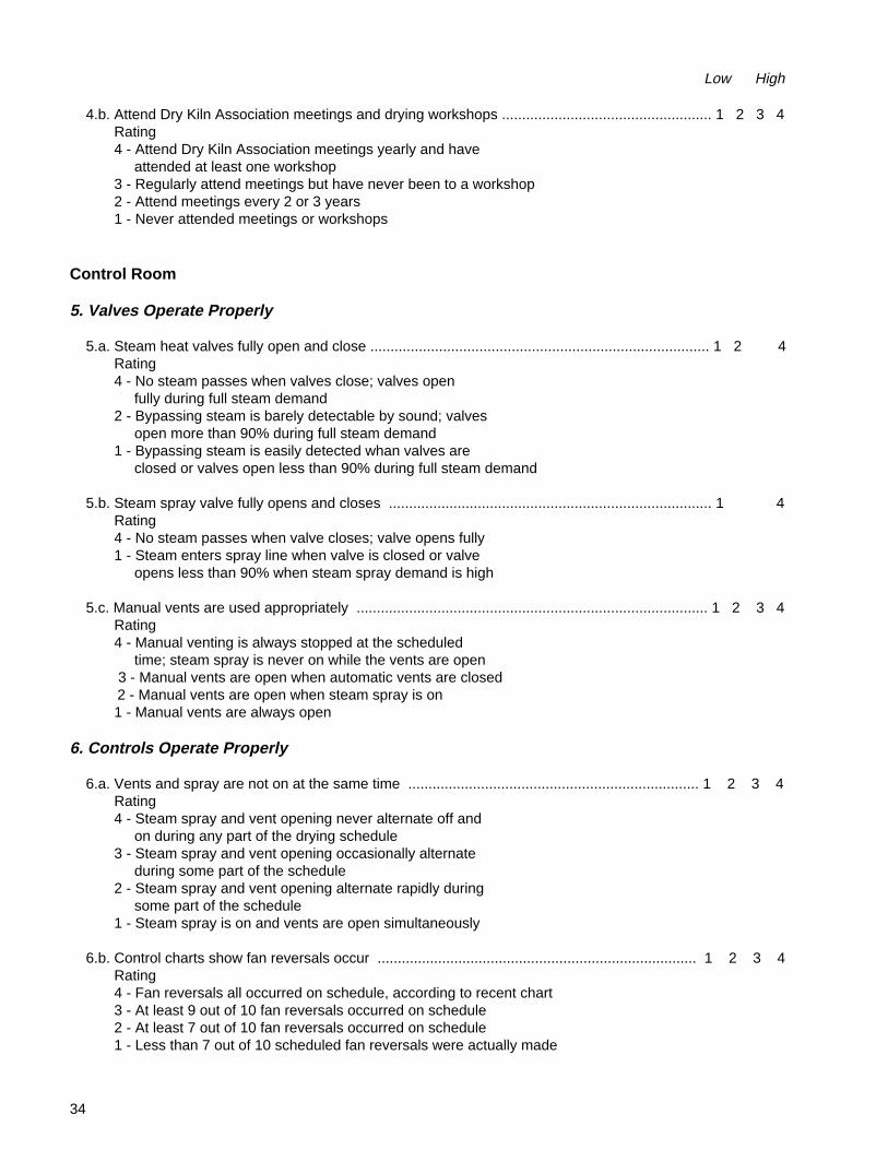
34
Low High
4.b. Attend Dry Kiln Association meetings and drying workshops .................................................... 1 2 3 4 Rating 4 - Attend Dry Kiln Association meetings yearly and have attended at least one workshop 3 - Regularly attend meetings but have never been to a workshop 2 - Attend meetings every 2 or 3 years 1 - Never attended meetings or workshops
Control Room
5. Valves Operate Properly
5.a. Steam heat valves fully open and close .................................................................................... 1 2 4 Rating 4 - No steam passes when valves close; valves open fully during full steam demand 2 - Bypassing steam is barely detectable by sound; valves open more than 90% during full steam demand 1 - Bypassing steam is easily detected whan valves are closed or valves open less than 90% during full steam demand
5.b. Steam spray valve fully opens and closes ................................................................................ 1 4 Rating 4 - No steam passes when valve closes; valve opens fully 1 - Steam enters spray line when valve is closed or valve opens less than 90% when steam spray demand is high
5.c. Manual vents are used appropriately ....................................................................................... 1 2 3 4 Rating 4 - Manual venting is always stopped at the scheduled time; steam spray is never on while the vents are open
3 - Manual vents are open when automatic vents are closed 2 - Manual vents are open when steam spray is on
1 - Manual vents are always open
6. Controls Operate Properly
6.a. Vents and spray are not on at the same time ........................................................................ 1 2 3 4 Rating 4 - Steam spray and vent opening never alternate off and on during any part of the drying schedule 3 - Steam spray and vent opening occasionally alternate during some part of the schedule 2 - Steam spray and vent opening alternate rapidly during some part of the schedule 1 - Steam spray is on and vents are open simultaneously
6.b. Control charts show fan reversals occur ............................................................................... 1 2 3 4 Rating 4 - Fan reversals all occurred on schedule, according to recent chart 3 - At least 9 out of 10 fan reversals occurred on schedule 2 - At least 7 out of 10 fan reversals occurred on schedule 1 - Less than 7 out of 10 scheduled fan reversals were actually made
35
Low High
6.c. Setpoint changes are made according to the schedule .......................................................... 1 2 3 4 Rating 4 - Temperature setpoints and times are followed according to the schedule 3 - Temperature setpoints are followed and times are never more than 2 hours off 2 - Setpoint changes are made but times are not according to the schedule 1 - Schedule is not closely followed
6.d. Correct control charts are used ............................................................................................ 1 4 Rating 4 - Chart paper matches recording instrument 1 - Wrong chart paper is used
Fan Deck and Kiln Roof
7. Fans
7.a. Fans and shrouds are well maintained ................................................................................ 1 2 4 Rating 4 - All fans are tight on the shaft, centered in shroud both radially and axially, and there is no blade damage 2 - One of the above is not correct 1 - More than one problem is found
7.b. Fans turning for proper airflow ............................................................................................. 1 3 4
Line shaft kilns Cross shaft kilns Rating Rating
4 - All fans proper "handedness" and pitch set correctly3 - All fans proper "handedness" but pitch not set correctly1 - One or more fans wrong "handedness" or not turning
4 - All fan motors turn the same direction and pitch set correctly3 - All fan motors turn the same direction but pitch not set correctly1 - One or more fan motors turning the wrong direction or fan not turning
8. Heat Distribution Systems
8.a. Steam heating coils clean and free of debris ........................................... ........................... 1 2 3 4
Kilns with fin pipe Kilns without fin pipe Rating Rating 4 - Can see space between fins; 4 - Coils are clean coils look clean 3 - Small amounts of dirt, 3 - Some dirt, rust, or coating rust, or coating on coils on coils or between fins 2 - Moderate dirt, rust, or 2 - Moderate dirt, rust, or coating on coils
coating; difficult to see pipe 1 - Heavy dirt, rust, coating, 1 - Cannot see pipe in places or or foreign material on coils foreign material on coils
8.b. Steam heating coil baffles present ........................................................... ............................ 1 2 3 4 Rating 4 - Baffles direct all air through the heating coils 3 - Most of the space is baffled 2 - Baffling is present but there are openings more than 12 in. wide 1 - Air by-passes heating coils
36
Low High
8.c. Direct-fired, heat distribution system structurally sound and clean ................................... 1 2 3 4 Rating
4 - Risers cleared of ash and dust weekly, and ductwork inspected quarterly for structural integrity
3 - Risers cleared of ash and dust twice a month, and ductwork inspected semiannually for structural integrity
2 - Risers cleared of ash and dust only when deposits on lumber are excessive, and ductwork inspected annually for structural integrity
1 - Cleaning and inspection not regularly made
9. Vents
9.a. Vent lids open and close fully ............................................................................................ 1 2 3 4 Rating 4 - All vent lids open to the same height; no vent leakage can be seen or felt with vents closed 3 - Slight leakage around vent lids; a little vapor can be seen from outside but light cannot be seen around vents from inside kiln 2 - Major leakage of vent lids or light can be seen around vents when they are in the closed position 1 - Vent lids do not close, leak significantly; one or more vent lids bent or broken
9.b. Vent actuators and linkages operate properly .................................................................. 1 2 3 4 Rating 4 - Vent actuators and mechanical linkages open vent lid to proper height 3 - Mechanical linkage is worn so vents only partially open or desired vent opening height cannot be achieved for other reasons 2 - One or more vent lids disconnected from connecting linkage 1 - Vents inoperative; vent activators not functioning or linkages disconnected
Yard Area
10. Sticker and Bolster Thickness
10.a. Sticker thickness uniformity ........................................................................................... 1 2 3 4 Rating 4 - Range of sticker thickness is 1/32 in. (0.031 in.) or less 3 - Range of sticker thickness is 1/16 in. (0.063 in.) or less 2 - Range of sticker thickness is 1/8 in. (0.125 in.) or less 1 - Range of sticker thickness is greater than 1/8 in. (0.125 in.)
10.b. Bolster thickness uniformity ............................................................................................. 1 2 3 4 Rating 4 - Range of bolster thickness is 1/8 in. (0.125 in.) or less 3 - Range of bolster thickness is 1/4 in. (0.250 in.) or less 2 - Range of bolster thickness is 3/8 in. (0.375 in.) or less 1 - Range of bolster thickness is greater than 3/8 in. (0.375 in.)
10.c. Green lumber inventory control ...................................................................................... 1 3 4 Rating 4 - Lumber tagging and inventory control system ensures lumber sawn first is dried first 3 - Kiln scheduling is done so most of the time the lumber sawn first is dried first 1 - No inventory control; packages can get “lost” in the yard
37
Inside an Empty Kiln
11. Inside a Cold Kiln
11.a. Condensation or other water inside kiln .......................................................................... 1 2 3 4 Rating 4 - No evidence of condensation or water in kiln 3 - Some evidence of condensation near walls, at the base of structural members or under vents, or small water leaks 2 - Much evidence of condensation, corrosion problems, or water leaks 1 - Kiln damage due to condensation or large amounts of water entering kiln
11.b. Reheat (center) coils clean and free of debris ................................................................ 1 2 3 4
Kilns with fin pipe Kilns without fin pipe Rating Rating 4 - Can see space between fins; 4 - Coils are clean coils look clean 3 - Some dirt, rust, or coating 3 - Small amounts of dirt, on coils or between fins rust, or coating on coils 2 - Moderate dirt, rust, or 2 - Moderate dirt, rust, or coating; difficult to see pipe coating on coils 1 - Cannot see pipe in places or 1 - Heavy dirt, rust, coating, or foreign material on coils foreign material on coils
11.c. Proper wet-bulb wick is used ............................................................. .............................. 1 2 3 4 Rating 4 - Wick is thick, 100% cotton, and feels very wet to the touch 3 - Wick feels soft but is only damp, not wet 2 - Wick feels crusted on top and is damp, not wet
1 - Wick is crusted and dry
11.d. Adequate water flowing to wet-bulb ................................................................................... 1 2 4 Rating 4 - Water runs out of wet-bulb pan at a rate between 1/8 and 1/2 cup in 3 minutes 2 - Wick is wet but there is less than 1/8 cup of water or more than 1/2 cup overflowing the pan in 3 minutes 1 - Wick is barely damp or dry or pan is empty
12. Kiln Operational Checks
12.a. Heating coils and steam pipe free of steam or water leaks ............................................... 1 2 3 4 (See section 12.a in the Guidebook for definitions of leaks.) Rating 4 - No leaks present 3 - Small leaks around fittings, in coils, or in steam pipes 2 - Several small leaks or one medium leak 1 - Several medium or large leaks
12.b. Steam spray free of liquid water ....................................................................................... 1 2 4 Rating 4 - No liquid water comes out when steam spray comes on, drain line is open, no water spots on lumber 2 - Improper slope on line or drainage point is blocked 1 - Water spots on lumber that can be traced to the steam spray line or spray line not draining to outside of kiln
Low High
38
Low High
12.c. Steam spray uniformly distributed ..................................................................................... 1 2 4 Rating 4 - All nozzles appear to produce equal amounts of steam 2 - Steam spray appears not uniform or one nozzle plugged 1 - More than one nozzle plugged
While Preparing Charges and Loading the Kiln
13. Lumber Quality and Package Loading
13.a. Lumber thickness variation ................................................................................................ 1 2 3 4 (See Fig. 1 in section 13.a of the Guidebook for examples.) Rating 4 - All boards are of uniform thickness and touching stickers; stickers are not bent 3 - Fewer than 10 boards per package do not touch stickers or stickers bend slightly over thick and thin lumber 2 - Thickness variation is sufficient to bend stickers or show gaps more than 1/8 in. wide above boards 1 - Thickness variation is great enough to make stacking visibly irregular
13.b. Package arrangement to accommodate short packages ................................................. 1 2 4 (See Fig. 2 in section 13.b of the Guidebook.) Rating 4 - Shorter length packages are always on the top and away from the top and end baffles so there are no voids 2 - Voids are next to the top or end baffles but these do not go through the load 1 - Openings go through the load
14. Package Support
14.a. Bottom load support uniformity ........................................................................................ 1 2 3 4
Track kilns Package kilns Rating Rating 4 - All kiln trucks equal height 4 - All load supports equal height 3 - One kiln truck more than 1/4 in. 3 - One or 2 load supports more than higher or lower than others 1/4 in. higher or lower than others 2 - Two or 3 kiln trucks more than 2 - Four to 6 load supports 1/4 in. higher or lower than others more than 1/4 in. lower than others 1 - Four or more kiln trucks more 1 - More than 6 load supports than 1/4 in. higher or more than 1/4 in. lower than others higher or lower than others
14.b. Rails (track-loaded kilns) ........................................................................ ........................ 1 2 3 4 Rating 4 - All rails level and well supported with no sign of deflection 3 - Rails settle or move slightly in one or two places 2 - Dips in rails or more than 1/2 in. of deflection when loaded 1 - Rails visibly out of level or have a large amount of deflection
39
15.b. Confirm that traps are functioning ................................................................................... 1 2 3 4 Rating 4 - All traps are working 3 - Traps do not quite handle condensate during startup 2 - Traps are undersized for startup and hold back a large amount of condensate 1 - One or more traps are not working
16. While Kiln Is Operating
16.a. Doors, walls, and roof free of leaks ................................................................................. 1 2 3 4 (See section 16.a in the Guidebook for definition of leaks.) Rating 4 - No leaks are visible or only slight leaks around rails 3 - Slight leaks around doors or other small leaks 2 - Large leaks 1 - Holes visible in the kiln structure
16.b. Confirm fan reversal by feeling airflow direction .............................................................. 1 4 Rating 4 - Airflow actually reverses 1 - Airflow does not actually reverse when timer or control chart indicates it should
After Drying is Completed
17. Before Unloading Kiln
17.a. Pile height uniform ............................................................................................................ 1 2 3 4 Rating 4 - All pile heights are the same 3 - Pile height varies only on the side away from the top baffle 2 - Pile height varies up to 6 in. on the top baffle side 1 - Pile height varies by more than 6 in. on the top baffle side
17.b. Baffles used properly ........................................................................................................ 1 2 3 4 Rating 4 - Baffles are placed flush against the top, bottom, and ends of load and were held securely during drying 3 - No spaces greater than 6 in. between the baffles and the load and baffles were held securely 2 - No spaces greater than 12 in. between the baffles and the load and baffles were held securely 1 - Baffles are missing, bent, or openings are greater than 12 in. between the baffles and the load; any baffles were unsecured
Low HighDuring Kiln Startup and Operation
15. During Kiln Startup
15.a. Adequate airflow across wet-bulb .................................................................................... 1 2 3 4 Rating 4 - Can easily feel air move across wick 3 - Airflow is not easy to feel but a handkerchief can be blown by the air 2 - Cannot feel air movement 1 - Wet-bulb is blocked from airflow
40
17.c. Adequate plenum width .................................................................................................... 1 2 3 4 Rating 4 - Plenum width equals the sum of the sticker and bolster openings 3 - Plenum width is between 3/4 and 1-1/4 times the sum of the sticker and bolster openings 2 - Plenum width is between 1/2 and 1-1/2 times the sum of the sticker and bolster openings 1 - Plenum width is less than 1/2 or more than 1-1/2 times the sum of the sticker and bolster openings
18. Before Piles Are Broken Down
18.a. Spot check MC with a moisture meter ............................................ ................................. 1 2 3 4 (See Fig. 3 and section 18.a in the Guidebook for check boards as described.)
Target MC below 13% Target MC above 13% or or MC variation is critical MC variation is less critical Rating Rating 4 - All individual board readings 4 - All individual board within 3% MC of target and readings within 5% MC of all averages within 2% target and all averages MC of target within 3% MC of target 3 - All individual board readings 3 - All individual board within 5% MC of target and readings within 8% MC or all averages within 3% MC target and all averages of target within 4% MC of target 2 - More than 10 individual 2 - More than 10 individual readings differ from target by readings differ from target by more than 6% but all averages more than 8% but all averages are within 4% of target are within 5% of target 1 - More than 20 individual 1 - More than 20 individual readings differ from target readings differ from target by by more than 6% or any more than 8% or any average average is more than 4% is more than 5% away from away from target target
18.b. Dry end covered .............................................................................. ................................ 1 2 3 4 Rating 4 - Dry end storage is covered with a protective shed 3 - Covered shed allows wind-driven rain to wet the lumber 2 - Shed leaks 1 - No protection from weather
Evaluate Stacking and Its Effect on Drying Quality
19. Sticker Placement
19.a. Sticker alignment ............................................................................................................. 1 2 3 4 (See Figs. 4 and 5 in section 19.a of the Guidebook.) Rating 4 - All stickers vertically aligned or less than 2 stickers out of alignment 3 - Fewer than 5 stickers out of alignment 2 - Fewer than 10 stickers out of alignment 1 - More than 10 stickers out of alignment
Low High
41
19.b. Stickers missing ............................................................................................................... 1 2 3 4 Rating 4 - All stickers present or less than 2 stickers missing 3 - Fewer than 5 stickers missing 2 - Fewer than 10 stickers missing 1 - More than 10 stickers missing
19.c. Stickers on edge .............................................................................................................. 1 2 3 4 Rating 4 - All stickers flat or less than 2 stickers on edge 3 - Fewer than 5 stickers on edge 2 - Fewer than 10 stickers on edge 1 - More than 10 stickers on edge
19.d. Double stickers (one on top of the other) ......................................................................... 1 2 3 4 Rating 4 - No double stickers or only one set 3 - Fewer than 3 sets of double stickers 2 - Fewer than 5 sets of double stickers 1 - More than 5 sets of double stickers
19.e. Sticker placement at ends of packages ........................................................................... 1 2 3 4 Rating 4 - All stickers within 1 sticker width of package ends 3 - Fewer than 3 stickers are more than 2 sticker widths in from the end 2 - Fewer than 5 stickers are more than 2 sticker widths in from the end 1 - More than 8 stickers are more than 2 sticker widths in from the end
20. Board Placement in Packages
20.a. Packages are square at both ends .................................................................................. 1 2 3 4 Rating 4 - All boards in all packages reach and are supported by the end sticker; ends of package are vertical 3 - Fewer than 5 boards do not reach the end sticker or extend 3 to 6 in. beyond it 2 - Fewer than 10 boards do not reach the end sticker or extend 6 to 12 in. beyond it 1 - More than 10 boards do not reach the end sticker or extend more than 12 in. beyond it
20.b. Sides of package even .................................................................................................... 1 2 3 4 (See Fig. 6 in section 20.b of the Guidebook.) Rating 4 - All sides of packages toward plenum are even 3 - Fewer than 10 courses on plenum side are not even 2 - Fewer than 30 courses on plenum side are not even 1 - More than 30 courses on plenum side are not even
20.c. Overlapped boards in package ....................................................................................... 1 2 3 4 Rating 4 - No overlapped boards can be seen 3 - Fewer than 3 sets of boards overlap 2 - Fewer than 5 sets of boards overlap 1 - More than 5 sets of boards overlap
Low High
42
21. Package and Bolster Placement
21.a. Bolster (bunk) placement ................................................................................................ 1 2 3 4 (See Fig. 7 in section 21.a of the Guidebook.) Rating 4 - All bolsters vertically aligned with every column of stickers 3 - One bolster out of alignment 2 - Two bolsters out of alignment 1 - More than two bolsters out of alignment
21.b. Package (crib) placement on supports ........................................................................... 1 2 3 4 (See Fig. 8 in section 21.b of the Guidebook.) Rating 4 - All bottom supports (truck or floor) are vertically aligned under stickers 3 - One truck or 2 bottom load supports not in vertical alignment with the column of stickers 2 - Two trucks or 4 bottom load supports not in alignment 1 - More than 2 trucks or 4 bottom load supports not in alignment
21.c. Chimney allowance between packages when loading kiln trucks ................................... 1 2 3 4 (See Fig. 9 in section 21.c of the Guidebook.) Rating 4 - Chimney between adjacent packages is 2 to 3 in. wide and is restricted at the top 3 - Chimney is 2 to 3 in. wide but is not restricted at the top 2 - Chimney is 3 to 6 in. wide but is not restricted at the top 1 - Chimney is larger than 6 in.
21.d. Packages placed at edge of kiln trucks ........................................................................... 1 2 3 4 Rating 4 - All packages are placed within 1 in. of the outside edge of the kiln truck supports 3 - One package is not even with the edge of the kiln truck supports 2 - Two packages are not even with the edge of the kiln truck supports 1 - More than two packages are not even with the edge of the kiln truck supports
Drying Defects and Drying Problems Reported
22. Drying Defects
22.a. Drying defects related to stickering and stacking ............................................................ 1 2 3 4
(This includes all distortions that can be related to sticker and bolster misplacement in any form. Bow, crook, twist, end splits, kink, and sag occurring because boards are not properly supported are included. Do not include warp in the top 2 or 3 courses at this time. See Fig. 10 in section 22.a of the Guidebook for illustrations of the types of warp.)
Rating 4 - No warp or defects observed 3 - Warp or defects in less than 10 boards 2 - Warp or defects in less than 20 boards 1 - Warp or defects in more than 20 boards
Low High
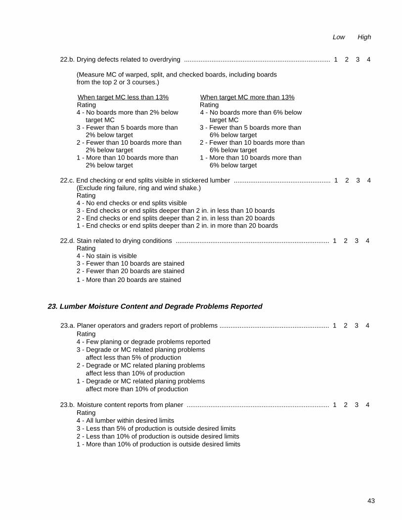
43
22.b. Drying defects related to overdrying ................................................................................ 1 2 3 4
(Measure MC of warped, split, and checked boards, including boards from the top 2 or 3 courses.)
When target MC less than 13% When target MC more than 13% Rating Rating 4 - No boards more than 2% below 4 - No boards more than 6% below target MC target MC 3 - Fewer than 5 boards more than 3 - Fewer than 5 boards more than 2% below target 6% below target 2 - Fewer than 10 boards more than 2 - Fewer than 10 boards more than 2% below target 6% below target 1 - More than 10 boards more than 1 - More than 10 boards more than 2% below target 6% below target
22.c. End checking or end splits visible in stickered lumber ..................................................... 1 2 3 4 (Exclude ring failure, ring and wind shake.) Rating 4 - No end checks or end splits visible 3 - End checks or end splits deeper than 2 in. in less than 10 boards 2 - End checks or end splits deeper than 2 in. in less than 20 boards 1 - End checks or end splits deeper than 2 in. in more than 20 boards
22.d. Stain related to drying conditions .................................................................................... 1 2 3 4 Rating 4 - No stain is visible 3 - Fewer than 10 boards are stained 2 - Fewer than 20 boards are stained 1 - More than 20 boards are stained
23. Lumber Moisture Content and Degrade Problems Reported
23.a. Planer operators and graders report of problems ............................................................ 1 2 3 4 Rating 4 - Few planing or degrade problems reported 3 - Degrade or MC related planing problems affect less than 5% of production 2 - Degrade or MC related planing problems affect less than 10% of production 1 - Degrade or MC related planing problems affect more than 10% of production
23.b. Moisture content reports from planer .............................................................................. 1 2 3 4 Rating 4 - All lumber within desired limits 3 - Less than 5% of production is outside desired limits 2 - Less than 10% of production is outside desired limits 1 - More than 10% of production is outside desired limits
Low High

44
Appendix 1—Summary Checklist forQuality Drying of Softwood Lumber
Appendix 1 contains all the items from the checklistand in the same order; only the rating system hasbeen omitted. This will shorten the number ofchecklist pages, and filing the checklist with thekiln records will require less space.
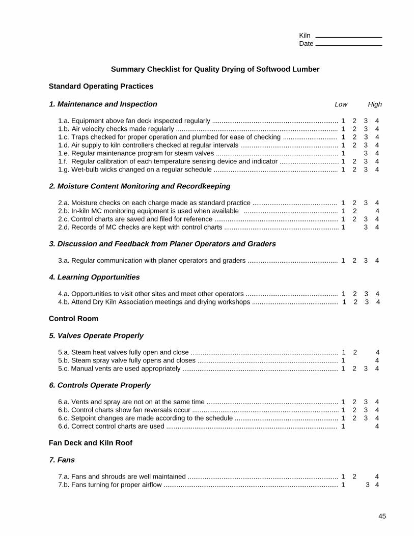
45
Kiln Date
Summary Checklist for Quality Drying of Softwood Lumber
Standard Operating Practices
1. Maintenance and Inspection Low High
1.a. Equipment above fan deck inspected regularly ................................................................... 1 2 3 4 1.b. Air velocity checks made regularly ...................................................................................... 1 2 3 4 1.c. Traps checked for proper operation and plumbed for ease of checking ............................. 1 2 3 4 1.d. Air supply to kiln controllers checked at regular intervals .................................................... 1 2 3 4 1.e. Regular maintenance program for steam valves ................................................................. 1 3 4 1.f. Regular calibration of each temperature sensing device and indicator ................................ 1 2 3 4 1.g. Wet-bulb wicks changed on a regular schedule .................................................................. 1 2 3 4
2. Moisture Content Monitoring and Recordkeeping
2.a. Moisture checks on each charge made as standard practice ............................................. 1 2 3 4 2.b. In-kiln MC monitoring equipment is used when available .................................................. 1 2 4 2.c. Control charts are saved and filed for reference .................................................................. 1 2 3 4 2.d. Records of MC checks are kept with control charts ............................................................. 1 3 4
3. Discussion and Feedback from Planer Operators and Graders
3.a. Regular communication with planer operators and graders ................................................ 1 2 3 4
4. Learning Opportunities
4.a. Opportunities to visit other sites and meet other operators ................................................. 1 2 3 4 4.b. Attend Dry Kiln Association meetings and drying workshops .............................................. 1 2 3 4
Control Room
5. Valves Operate Properly
5.a. Steam heat valves fully open and close .. ............................................................................ 1 2 4 5.b. Steam spray valve fully opens and closes ........................................................................... 1 4 5.c. Manual vents are used appropriately ................................................................................... 1 2 3 4
6. Controls Operate Properly
6.a. Vents and spray are not on at the same time ...................................................................... 1 2 3 4 6.b. Control charts show fan reversals occur .............................................................................. 1 2 3 4 6.c. Setpoint changes are made according to the schedule ....................................................... 1 2 3 4 6.d. Correct control charts are used ........................................................................................... 1 4
Fan Deck and Kiln Roof
7. Fans
7.a. Fans and shrouds are well maintained ................................................................................ 1 2 4 7.b. Fans turning for proper airflow ............................................................................................. 1 3 4
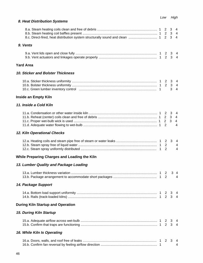
46
Low High 8. Heat Distribution Systems
8.a. Steam heating coils clean and free of debris ................................................................. 1 2 3 4 8.b. Steam heating coil baffles present ................................................................................. 1 2 3 4 8.c. Direct-fired, heat distribution system structurally sound and clean ............................... 1 2 3 4
9. Vents
9.a. Vent lids open and close fully ........................................................................................ 1 2 3 4 9.b. Vent actuators and linkages operate properly ............................................................... 1 2 3 4
Yard Area
10. Sticker and Bolster Thickness
10.a. Sticker thickness uniformity ............................................................................................ 1 2 3 4 10.b. Bolster thickness uniformity ............................................................................................ 1 2 3 4 10.c. Green lumber inventory control .................................................................................... 1 3 4
Inside an Empty Kiln
11. Inside a Cold Kiln
11.a. Condensation or other water inside kiln .......................................................................... 1 2 3 4 11.b. Reheat (center) coils clean and free of debris ................................................................ 1 2 3 4 11.c. Proper wet-bulb wick is used .......................................................................................... 1 2 3 4 11.d. Adequate water flowing to wet-bulb ................................................................................ 1 2 4
12. Kiln Operational Checks
12.a. Heating coils and steam pipe free of steam or water leaks ............................................ 1 2 3 4 12.b. Steam spray free of liquid water ..................................................................................... 1 2 4 12.c. Steam spray uniformly distributed .................................................................................. 1 2 4
While Preparing Charges and Loading the Kiln
13. Lumber Quality and Package Loading
13.a. Lumber thickness variation ............................................................................................. 1 2 3 4 13.b. Package arrangement to accommodate short packages ............................................... 1 2 4
14. Package Support
14.a. Bottom load support uniformity ....................................................................................... 1 2 3 4 14.b. Rails (track-loaded kilns) ................................................................................................ 1 2 3 4
During Kiln Startup and Operation
15. During Kiln Startup
15.a. Adequate airflow across wet-bulb ................................................................................... 1 2 3 4 15.b. Confirm that traps are functioning ................................................................................... 1 2 3 4
16. While Kiln Is Operating
16.a. Doors, walls, and roof free of leaks ................................................................................ 1 2 3 4 16.b. Confirm fan reversal by feeling airflow direction ............................................................. 1 4
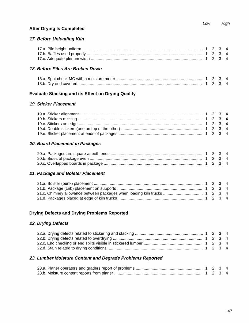
47
Low HighAfter Drying Is Completed
17. Before Unloading Kiln
17.a. Pile height uniform .......................................................................................................... 1 2 3 4 17.b. Baffles used properly ...................................................................................................... 1 2 3 4 17.c. Adequate plenum width .................................................................................................. 1 2 3 4
18. Before Piles Are Broken Down
18.a. Spot check MC with a moisture meter ............................................................................ 1 2 3 4 18.b. Dry end covered ............................................................................................................. 1 2 3 4
Evaluate Stacking and its Effect on Drying Quality
19. Sticker Placement
19.a. Sticker alignment ............................................................................................................ 1 2 3 4 19.b. Stickers missing .............................................................................................................. 1 2 3 4 19.c. Stickers on edge ............................................................................................................. 1 2 3 4 19.d. Double stickers (one on top of the other) ....................................................................... 1 2 3 4 19.e. Sticker placement at ends of packages .......................................................................... 1 2 3 4
20. Board Placement in Packages
20.a. Packages are square at both ends ................................................................................. 1 2 3 4 20.b. Sides of package even ................................................................................................... 1 2 3 4 20.c. Overlapped boards in package ....................................................................................... 1 2 3 4
21. Package and Bolster Placement
21.a. Bolster (bunk) placement ................................................................................................ 1 2 3 4 21.b. Package (crib) placement on supports ........................................................................... 1 2 3 4 21.c. Chimney allowance between packages when loading kiln trucks ................................... 1 2 3 4 21.d. Packages placed at edge of kiln trucks........................................................................... 1 2 3 4
Drying Defects and Drying Problems Reported
22. Drying Defects
22.a. Drying defects related to stickering and stacking ............................................................ 1 2 3 4 22.b. Drying defects related to overdrying ............................................................................... 1 2 3 4 22.c. End checking or end splits visible in stickered lumber .................................................... 1 2 3 4 22.d. Stain related to drying conditions ................................................................................... 1 2 3 4
23. Lumber Moisture Content and Degrade Problems Reported
23.a. Planer operators and graders report of problems ........................................................... 1 2 3 4 23.b. Moisture content reports from planer .............................................................................. 1 2 3 4

48
Appendix 2—Checklist Arranged byDrying System Components
Appendix 2 contains the same items as the checklist,but it is arranged so that all the components relatedto one system are together. For example, all theitems related to fans are grouped together. The itemnumber is the same as in the guidebook section.If you have a question about a particular item,refer to the guidebook by its item number(for example, 7.b.).
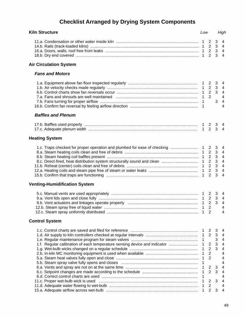
49
Checklist Arranged by Drying System Components
Kiln Structure Low High
11.a. Condensation or other water inside kiln .......................................................................... 1 2 3 4 14.b. Rails (track-loaded kilns) ................................................................................................. 1 2 3 4 16.a. Doors, walls, roof free from leaks .................................................................................... 1 2 3 4 18.b. Dry end covered .............................................................................................................. 1 2 3 4
Air Circulation System
Fans and Motors
1.a. Equipment above fan floor inspected regularly .............................................................. 1 2 3 4 1.b. Air velocity checks made regularly ................................................................................. 1 2 3 4 6.b. Control charts show fan reversals occur ......................................................................... 1 2 3 4 7.a. Fans and shrouds are well maintained .......................................................................... 1 2 4 7.b. Fans turning for proper airflow ........................................................................................ 1 3 4 16.b. Confirm fan reversal by feeling airflow direction ............................................................. 1 4
Baffles and Plenum
17.b. Baffles used properly ...................................................................................................... 1 2 3 4 17.c. Adequate plenum width .................................................................................................. 1 2 3 4
Heating System
1.c. Traps checked for proper operation and plumbed for ease of checking ......................... 1 2 3 4 8.a. Steam heating coils clean and free of debris .................................................................. 1 2 3 4 8.b. Steam heating coil baffles present .................................................................................. 1 2 3 4 8.c. Direct-fired, heat distribution system structurally sound and clean ................................. 1 2 3 4 11.b. Reheat (center) coils clean and free of debris ................................................................ 1 2 3 4 12.a. Heating coils and steam pipe free of steam or water leaks ............................................ 1 2 3 4 15.b. Confirm that traps are functioning ................................................................................... 1 2 3 4
Venting-Humidification System
5.c. Manual vents are used appropriately .............................................................................. 1 2 3 4 9.a. Vent lids open and close fully ......................................................................................... 1 2 3 4 9.b. Vent actuators and linkages operate properly ............................................................... 1 2 3 4 12.b. Steam spray free of liquid water .................................................................................... 1 2 4 12.c. Steam spray uniformly distributed .................................................................................. 1 2 4
Control System
1.c. Control charts are saved and filed for reference ............................................................. 1 2 3 4 1.d. Air supply to kiln controllers checked at regular intervals ............................................... 1 2 3 4 1.e. Regular maintenance program for steam valves ............................................................ 1 3 4 1.f. Regular calibration of each temperature sensing device and indicator .......................... 1 2 3 4 1.g. Wet-bulb wicks changed on a regular schedule ............................................................. 1 2 3 4 2.b. In-kiln MC monitoring equipment is used when available ............................................... 1 2 4 5.a. Steam heat valves fully open and close .......................................................................... 1 2 4 5.b. Steam spray valve fully opens and closes ..................................................................... 1 4 6.a. Vents and spray are not on at the same time ................................................................. 1 2 3 4 6.c. Setpoint changes are made according to the schedule .................................................. 1 2 3 4 6.d. Correct control charts are used ...................................................................................... 1 4 11.c. Proper wet-bulb wick is used ......................................................................................... 1 2 3 4 11.d. Adequate water flowing to wet-bulb ................................................................................ 1 2 4 15.a. Adequate airflow across wet-bulb ................................................................................... 1 2 3 4
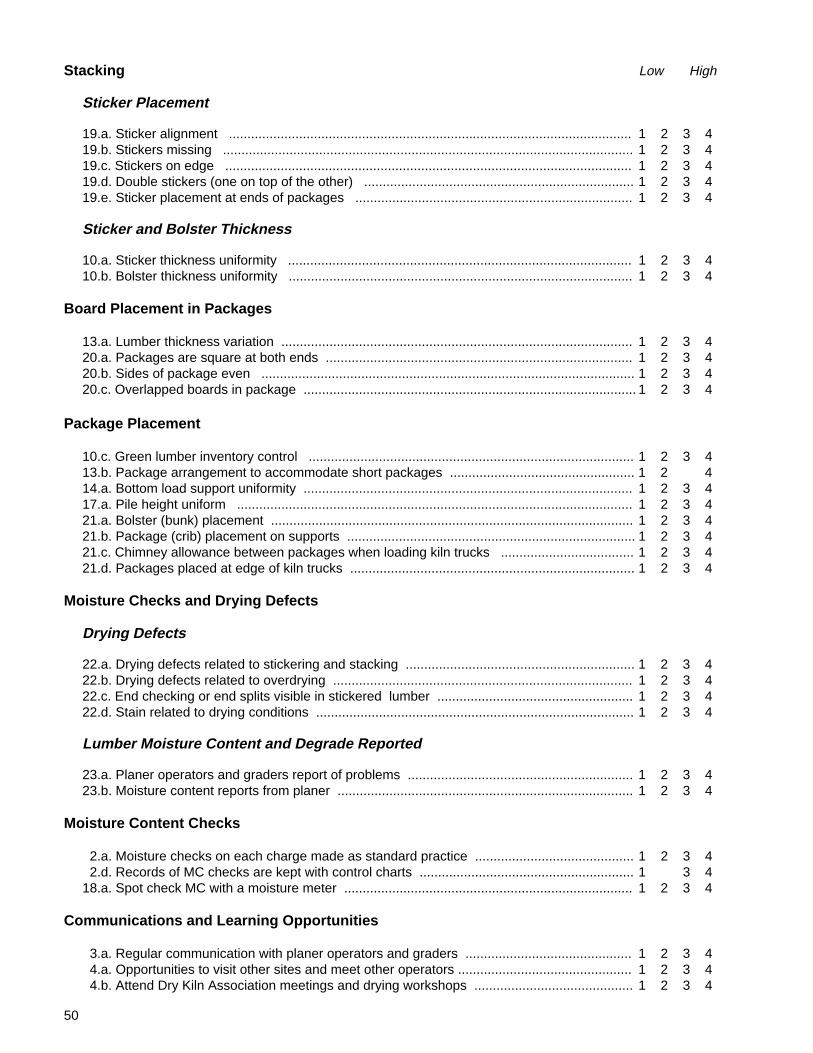
50
Stacking Low High
Sticker Placement
19.a. Sticker alignment ............................................................................................................. 1 2 3 4 19.b. Stickers missing ............................................................................................................... 1 2 3 4 19.c. Stickers on edge .............................................................................................................. 1 2 3 4 19.d. Double stickers (one on top of the other) ......................................................................... 1 2 3 4 19.e. Sticker placement at ends of packages ........................................................................... 1 2 3 4
Sticker and Bolster Thickness
10.a. Sticker thickness uniformity ............................................................................................. 1 2 3 4 10.b. Bolster thickness uniformity ............................................................................................. 1 2 3 4
Board Placement in Packages
13.a. Lumber thickness variation ............................................................................................... 1 2 3 4 20.a. Packages are square at both ends ................................................................................... 1 2 3 4 20.b. Sides of package even ..................................................................................................... 1 2 3 4 20.c. Overlapped boards in package .......................................................................................... 1 2 3 4
Package Placement
10.c. Green lumber inventory control ........................................................................................ 1 2 3 4 13.b. Package arrangement to accommodate short packages .................................................. 1 2 4 14.a. Bottom load support uniformity ......................................................................................... 1 2 3 4 17.a. Pile height uniform ........................................................................................................... 1 2 3 4 21.a. Bolster (bunk) placement .................................................................................................. 1 2 3 4 21.b. Package (crib) placement on supports .............................................................................. 1 2 3 4 21.c. Chimney allowance between packages when loading kiln trucks .................................... 1 2 3 4 21.d. Packages placed at edge of kiln trucks ............................................................................. 1 2 3 4
Moisture Checks and Drying Defects
Drying Defects
22.a. Drying defects related to stickering and stacking .............................................................. 1 2 3 4 22.b. Drying defects related to overdrying ................................................................................. 1 2 3 4 22.c. End checking or end splits visible in stickered lumber ..................................................... 1 2 3 4 22.d. Stain related to drying conditions ...................................................................................... 1 2 3 4
Lumber Moisture Content and Degrade Reported
23.a. Planer operators and graders report of problems ............................................................. 1 2 3 4 23.b. Moisture content reports from planer ................................................................................ 1 2 3 4
Moisture Content Checks
2.a. Moisture checks on each charge made as standard practice ........................................... 1 2 3 4 2.d. Records of MC checks are kept with control charts .......................................................... 1 3 4 18.a. Spot check MC with a moisture meter .............................................................................. 1 2 3 4
Communications and Learning Opportunities
3.a. Regular communication with planer operators and graders ............................................. 1 2 3 4 4.a. Opportunities to visit other sites and meet other operators ............................................... 1 2 3 4 4.b. Attend Dry Kiln Association meetings and drying workshops ........................................... 1 2 3 4


