www.alfalaval.com
− CIP in the brewery (and food and beverage applications)
Alyce Hartvigsen
29/04/2020 | © Alfa Laval 1 |
Principles of cleaning and CIP
www.alfalaval.com| © Alfa Laval 2 |29/04/2020
• Principles of cleaning and CIP
• CIP in the brewery (and food and beverage applications)
• Technologies for tank cleaning
• Optimization of CIP process
• Automated CIP solutions from Alfa Laval Brewery Systems
What we’ll talk about today− Agenda
www.alfalaval.com
Purpose of cleaning and CIP− Why do we clean?
29/04/2020 | © Alfa Laval 3 |
• Maintenance of product purity, quality and safety
• Prevention of product contamination (e.g.,
spoilage)
• Prevention of cross-contamination (e.g., ingress
of one product into another)
• Maximization of equipment uptime and production
capacity (fastest possible resumption of
production after completed batch)
• Maintenance of control of the production process
www.alfalaval.com29/04/2020 | © Alfa Laval 4 |
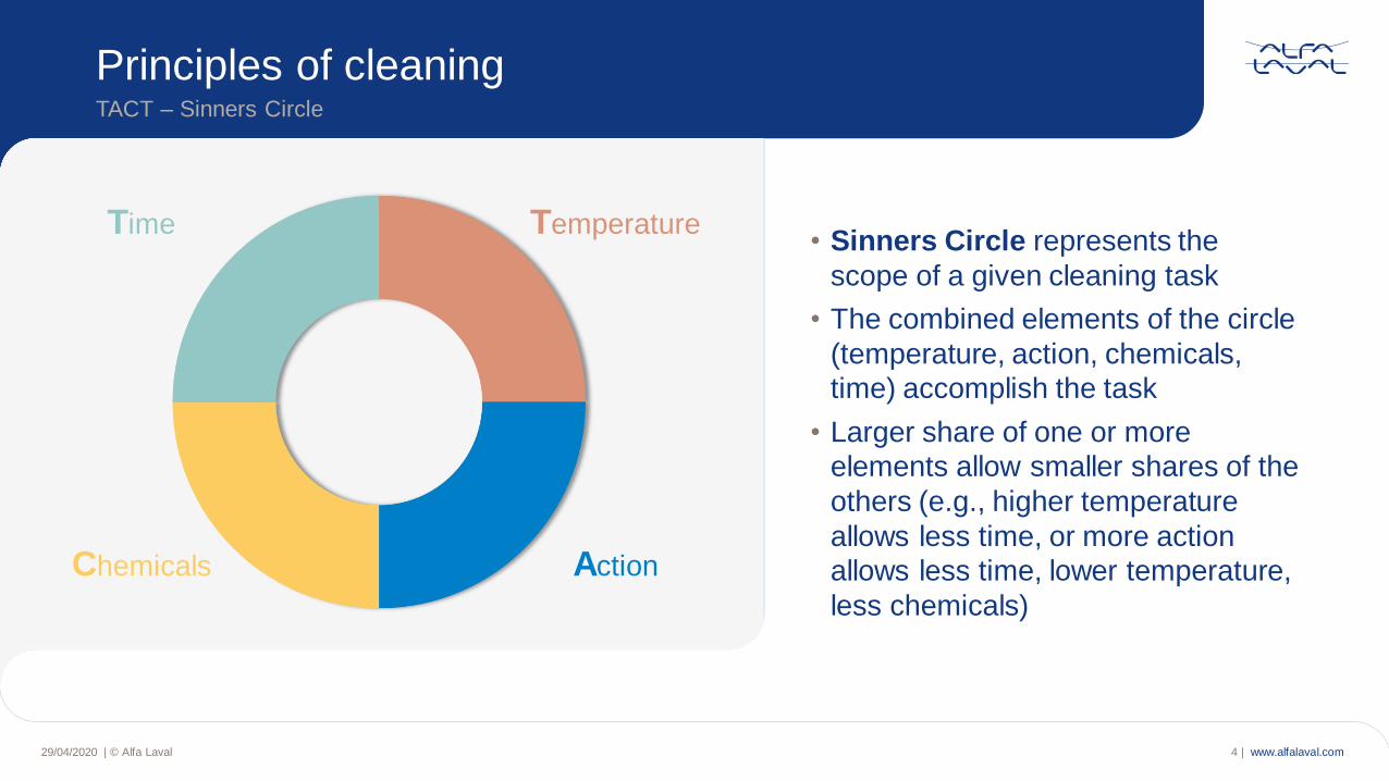
• Sinners Circle represents the
scope of a given cleaning task
• The combined elements of the circle
(temperature, action, chemicals,
time) accomplish the task
• Larger share of one or more
elements allow smaller shares of the
others (e.g., higher temperature
allows less time, or more action
allows less time, lower temperature,
less chemicals)
Principles of cleaningTACT – Sinners Circle
Temperature
Action
Time
Chemicals
www.alfalaval.com29/04/2020 | © Alfa Laval 5 |
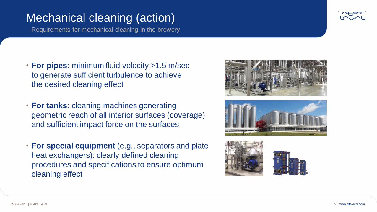
Mechanical cleaning (action)− Requirements for mechanical cleaning in the brewery
• For pipes: minimum fluid velocity >1.5 m/sec
to generate sufficient turbulence to achieve
the desired cleaning effect
• For tanks: cleaning machines generating
geometric reach of all interior surfaces (coverage)
and sufficient impact force on the surfaces
• For special equipment (e.g., separators and plate
heat exchangers): clearly defined cleaning
procedures and specifications to ensure optimum
cleaning effect
www.alfalaval.com
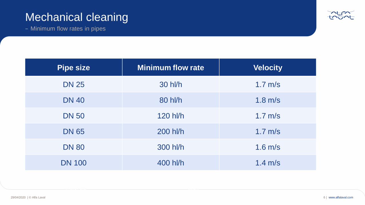
Mechanical cleaning− Minimum flow rates in pipes
© Alfa Laval Slide 6
29/04/2020 | © Alfa Laval 6 |
Pipe size Minimum flow rate Velocity
DN 25 30 hl/h 1.7 m/s
DN 40 80 hl/h 1.8 m/s
DN 50 120 hl/h 1.7 m/s
DN 65 200 hl/h 1.7 m/s
DN 80 300 hl/h 1.6 m/s
DN 100 400 hl/h 1.4 m/s
www.alfalaval.com29/04/2020 | © Alfa Laval 7 |
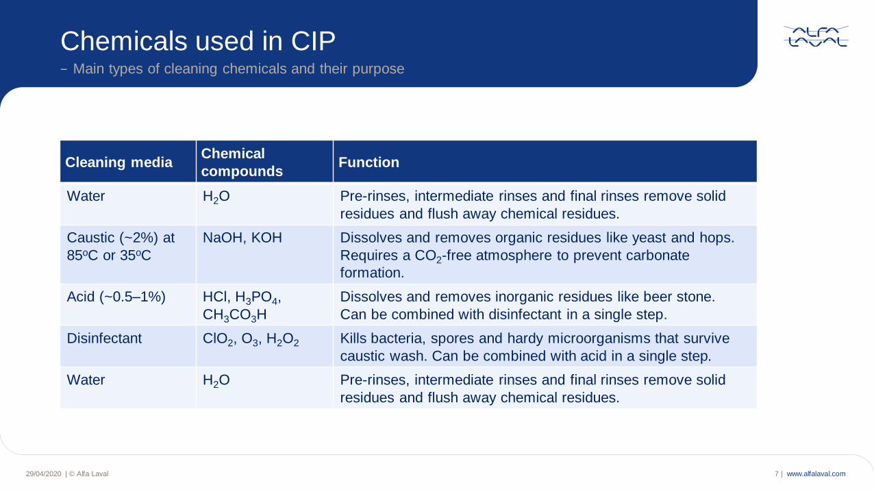
Chemicals used in CIP− Main types of cleaning chemicals and their purpose
Cleaning mediaChemical
compoundsFunction
Water H2O Pre-rinses, intermediate rinses and final rinses remove solid
residues and flush away chemical residues.
Caustic (~2%) at
85oC or 35oC
NaOH, KOH Dissolves and removes organic residues like yeast and hops.
Requires a CO2-free atmosphere to prevent carbonate
formation.
Acid (~0.5–1%) HCl, H3PO4,
CH3CO3H
Dissolves and removes inorganic residues like beer stone.
Can be combined with disinfectant in a single step.
Disinfectant ClO2, O3, H2O2 Kills bacteria, spores and hardy microorganisms that survive
caustic wash. Can be combined with acid in a single step.
Water H2O Pre-rinses, intermediate rinses and final rinses remove solid
residues and flush away chemical residues.
www.alfalaval.com29/04/2020 | © Alfa Laval 8 |
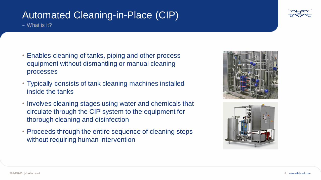
Automated Cleaning-in-Place (CIP)− What is it?
• Enables cleaning of tanks, piping and other process
equipment without dismantling or manual cleaning
processes
• Typically consists of tank cleaning machines installed
inside the tanks
• Involves cleaning stages using water and chemicals that
circulate through the CIP system to the equipment for
thorough cleaning and disinfection
• Proceeds through the entire sequence of cleaning steps
without requiring human intervention
www.alfalaval.com29/04/2020 | © Alfa Laval 9 |
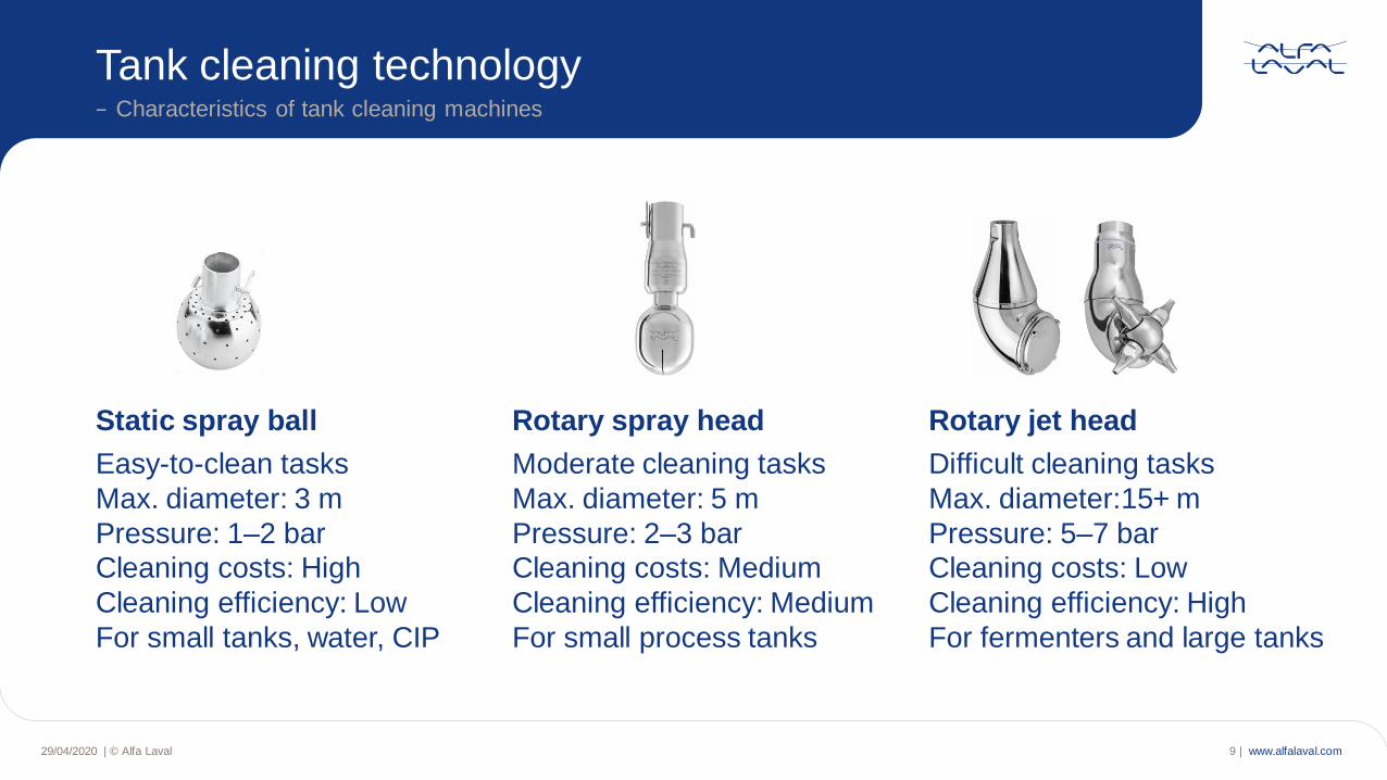
Tank cleaning technology− Characteristics of tank cleaning machines
Static spray ball Rotary spray head Rotary jet head
Easy-to-clean tasks Moderate cleaning tasks Difficult cleaning tasks
Max. diameter: 3 m Max. diameter: 5 m Max. diameter:15+ m
Pressure: 1–2 bar Pressure: 2–3 bar Pressure: 5–7 bar
Cleaning costs: High Cleaning costs: Medium Cleaning costs: Low
Cleaning efficiency: Low Cleaning efficiency: Medium Cleaning efficiency: High
For small tanks, water, CIP For small process tanks For fermenters and large tanks
www.alfalaval.com
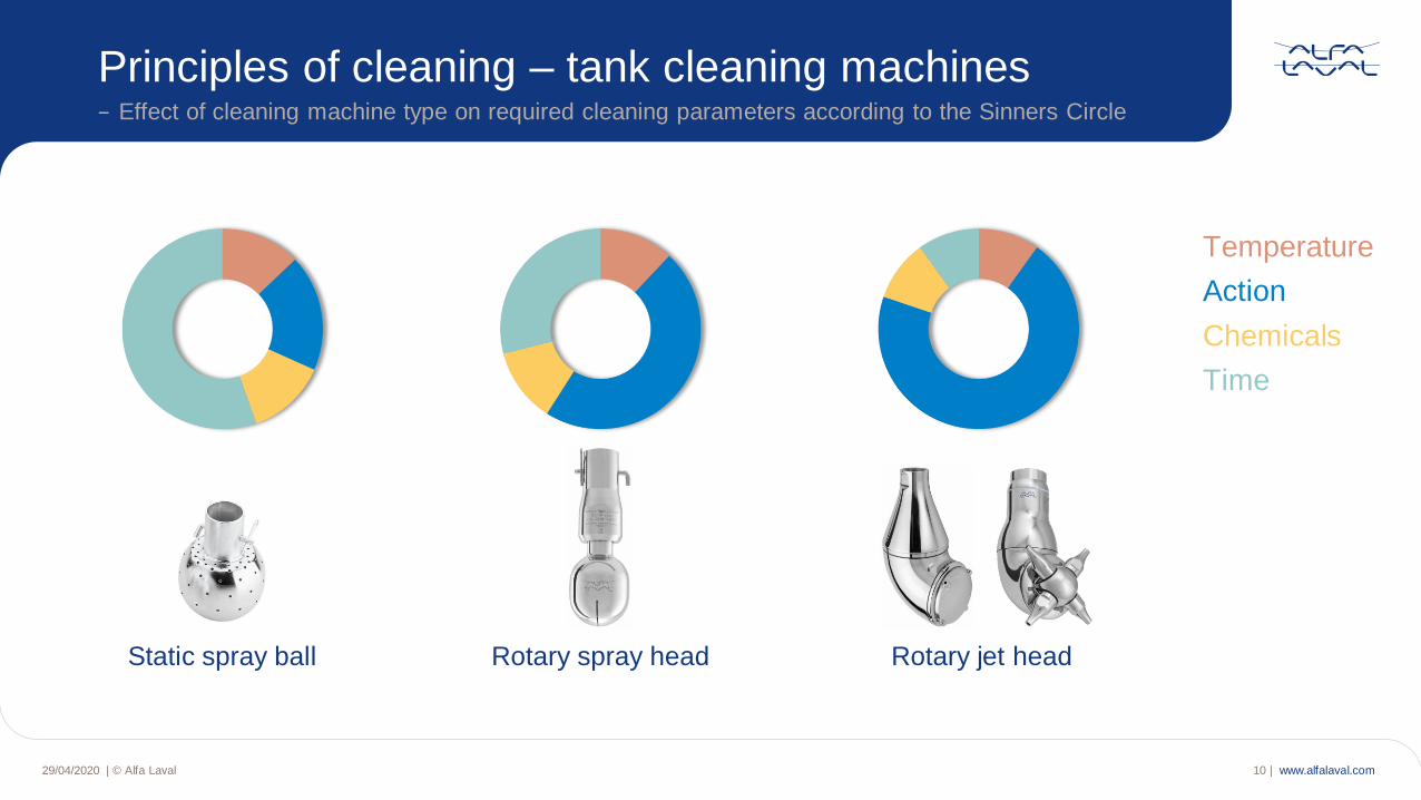
Principles of cleaning – tank cleaning machines− Effect of cleaning machine type on required cleaning parameters according to the Sinners Circle
Static spray ball Rotary spray head Rotary jet head
29/04/2020 | © Alfa Laval 10 |
Temperature
Action
Chemicals
Time
www.alfalaval.com
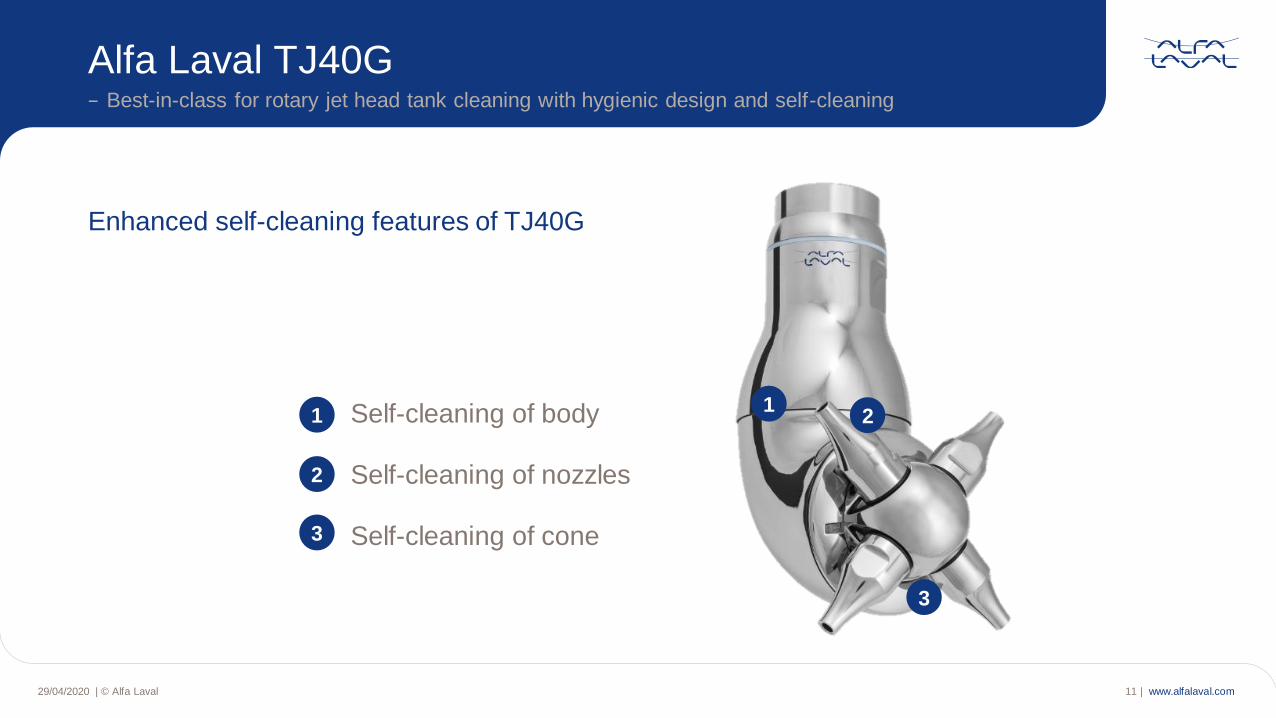
Enhanced self-cleaning features of TJ40G
12
3
1
2
3
Self-cleaning of body
Self-cleaning of nozzles
Self-cleaning of cone
− Best-in-class for rotary jet head tank cleaning with hygienic design and self-cleaning
Alfa Laval TJ40G
29/04/2020 | © Alfa Laval 11 |
www.alfalaval.com
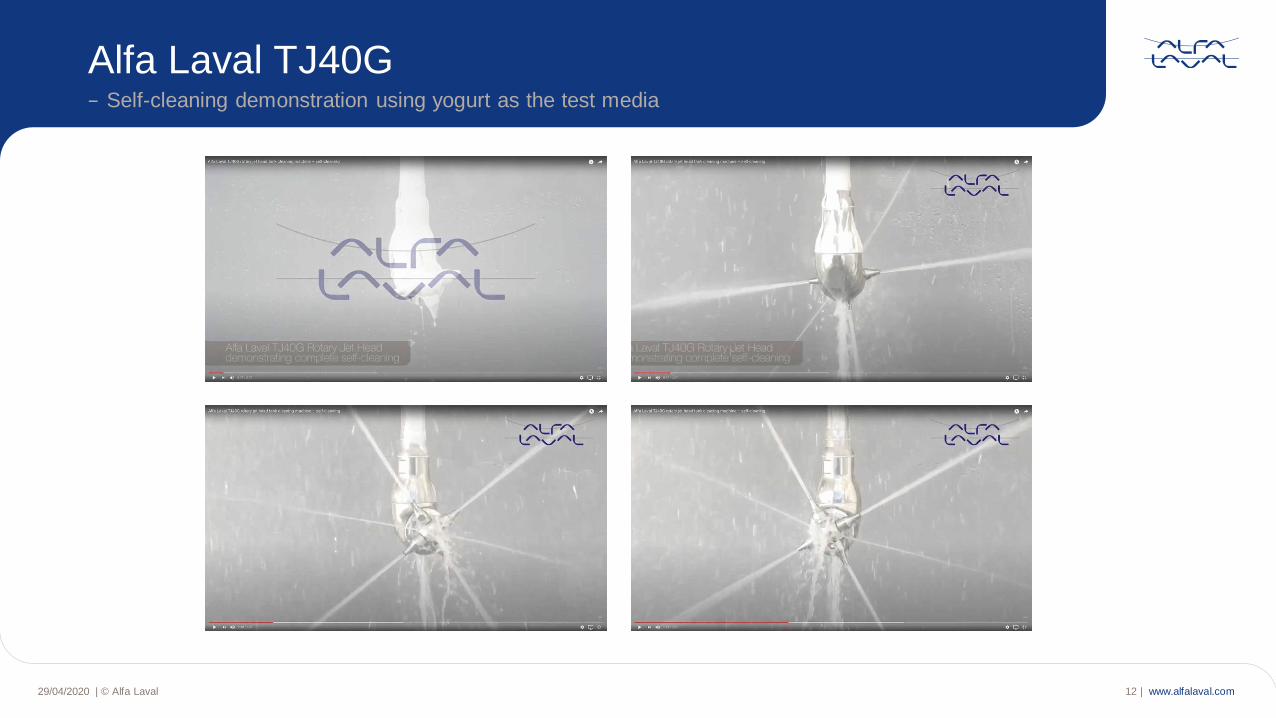
− Self-cleaning demonstration using yogurt as the test media
Alfa Laval TJ40G
29/04/2020 | © Alfa Laval 12 |
www.alfalaval.com
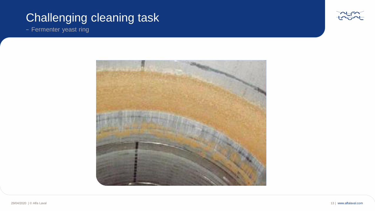
Challenging cleaning task− Fermenter yeast ring
29/04/2020 | © Alfa Laval 13 |
www.alfalaval.com
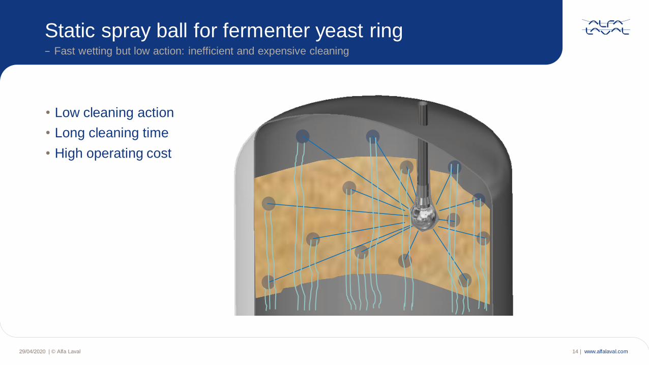
Static spray ball for fermenter yeast ring− Fast wetting but low action: inefficient and expensive cleaning
29/04/2020 | © Alfa Laval 14 |
• Low cleaning action
• Long cleaning time
• High operating cost
www.alfalaval.com
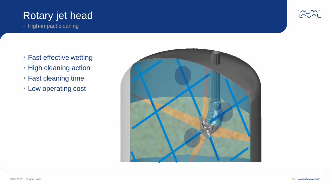
Rotary jet head− High-impact cleaning
29/04/2020 | © Alfa Laval 15 |
• Fast effective wetting
• High cleaning action
• Fast cleaning time
• Low operating cost
www.alfalaval.com29/04/2020 | © Alfa Laval 16 |
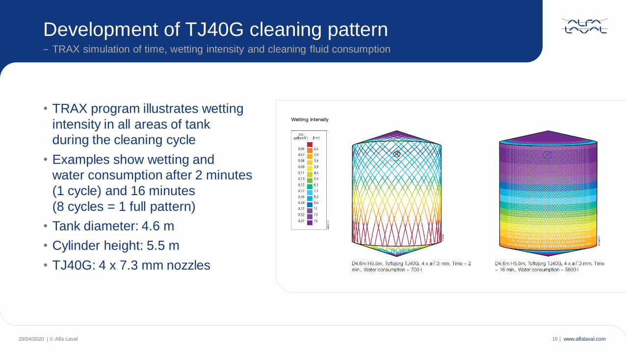
Development of TJ40G cleaning pattern− TRAX simulation of time, wetting intensity and cleaning fluid consumption
• TRAX program illustrates wetting
intensity in all areas of tank
during the cleaning cycle
• Examples show wetting and
water consumption after 2 minutes
(1 cycle) and 16 minutes
(8 cycles = 1 full pattern)
• Tank diameter: 4.6 m
• Cylinder height: 5.5 m
• TJ40G: 4 x 7.3 mm nozzles
www.alfalaval.com
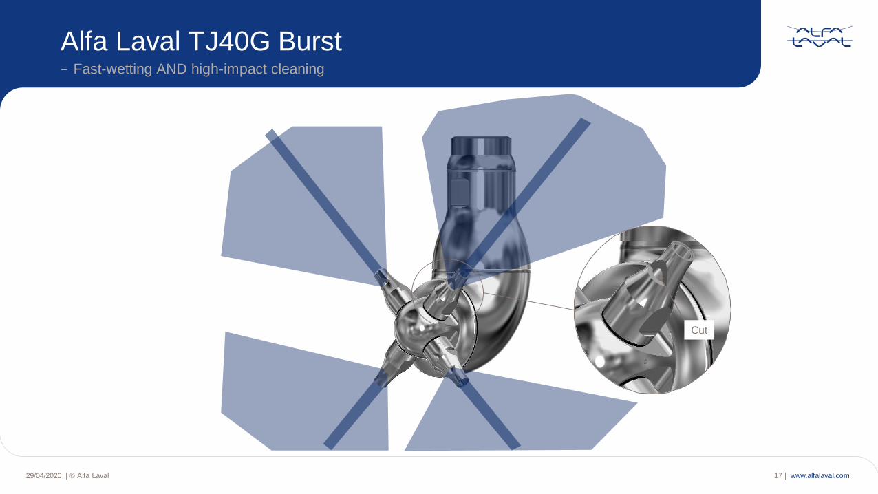
Alfa Laval TJ40G Burst− Fast-wetting AND high-impact cleaning
29/04/2020 | © Alfa Laval 17 |
Cut
www.alfalaval.com
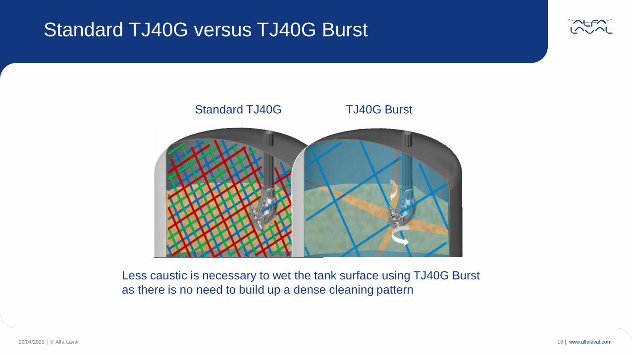
Standard TJ40G versus TJ40G Burst
Standard TJ40G TJ40G Burst
Less caustic is necessary to wet the tank surface using TJ40G Burst
as there is no need to build up a dense cleaning pattern
29/04/2020 | © Alfa Laval 18 |
www.alfalaval.com29/04/2020 | © Alfa Laval 19 |
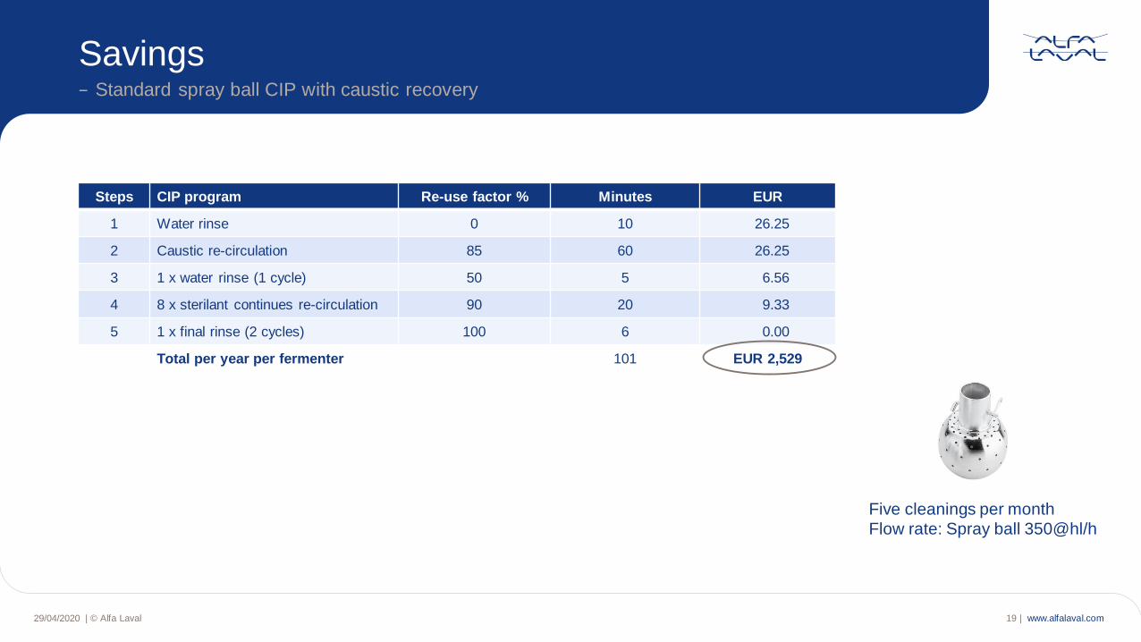
Savings− Standard spray ball CIP with caustic recovery
Steps CIP program Re-use factor % Minutes EUR
1 Water rinse 0 10 26.25
2 Caustic re-circulation 85 60 26.25
3 1 x water rinse (1 cycle) 50 5 6.56
4 8 x sterilant continues re-circulation 90 20 9.33
5 1 x final rinse (2 cycles) 100 6 0.00
Total per year per fermenter 101 EUR 2,529
Five cleanings per month
Flow rate: Spray ball 350@hl/h
www.alfalaval.com29/04/2020 | © Alfa Laval 20 |
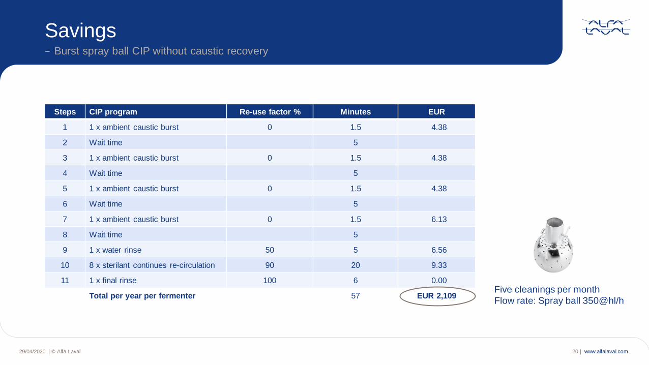
Savings − Burst spray ball CIP without caustic recovery
Steps CIP program Re-use factor % Minutes EUR
1 1 x ambient caustic burst 0 1.5 4.38
2 Wait time 5
3 1 x ambient caustic burst 0 1.5 4.38
4 Wait time 5
5 1 x ambient caustic burst 0 1.5 4.38
6 Wait time 5
7 1 x ambient caustic burst 0 1.5 6.13
8 Wait time 5
9 1 x water rinse 50 5 6.56
10 8 x sterilant continues re-circulation 90 20 9.33
11 1 x final rinse 100 6 0.00
Total per year per fermenter 57 EUR 2,109Five cleanings per month
Flow rate: Spray ball 350@hl/h
www.alfalaval.com
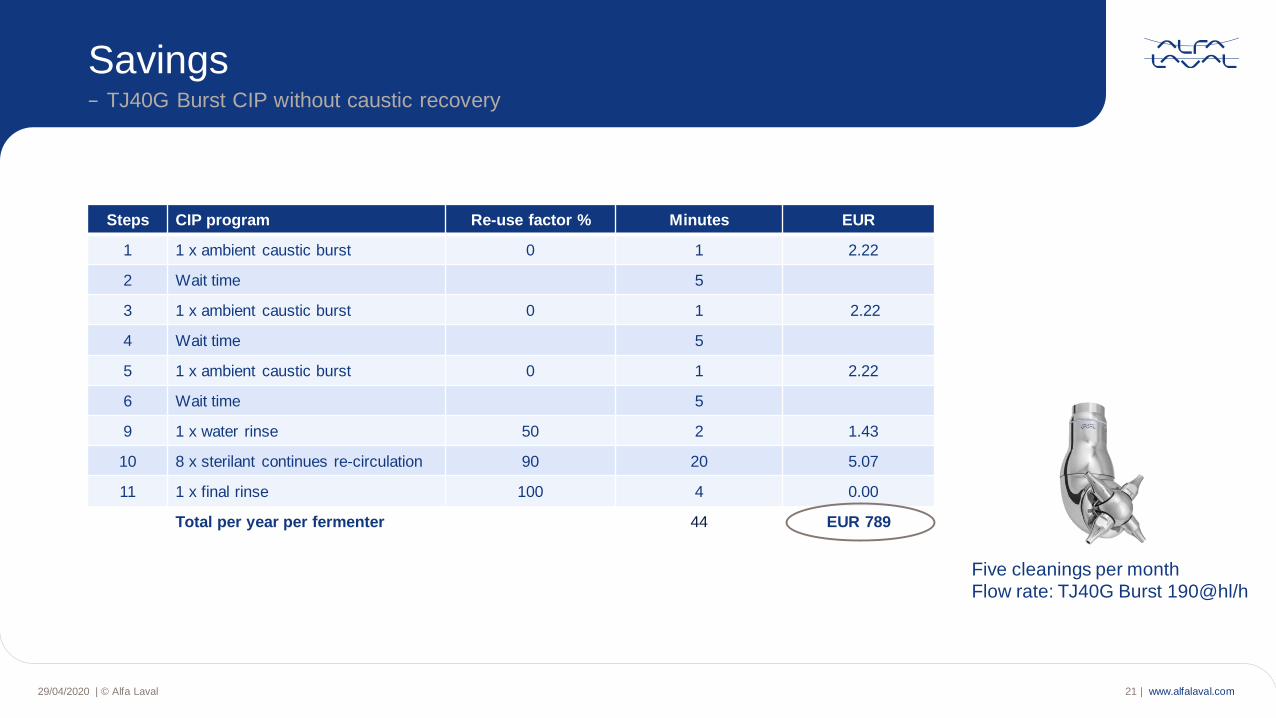
Steps CIP program Re-use factor % Minutes EUR
1 1 x ambient caustic burst 0 1 2.22
2 Wait time 5
3 1 x ambient caustic burst 0 1 2.22
4 Wait time 5
5 1 x ambient caustic burst 0 1 2.22
6 Wait time 5
9 1 x water rinse 50 2 1.43
10 8 x sterilant continues re-circulation 90 20 5.07
11 1 x final rinse 100 4 0.00
Total per year per fermenter 44 EUR 789
29/04/2020 | © Alfa Laval 21 |
Savings− TJ40G Burst CIP without caustic recovery
Five cleanings per month
Flow rate: TJ40G Burst 190@hl/h
www.alfalaval.com
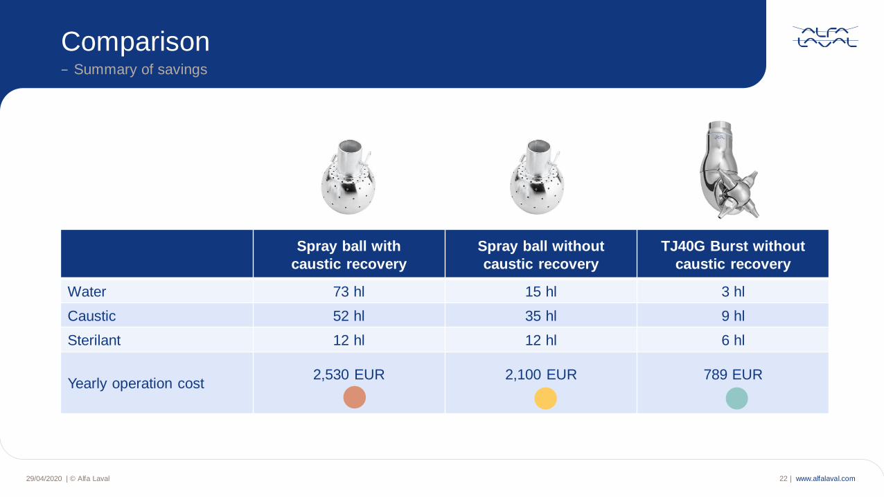
Comparison− Summary of savings
Spray ball with
caustic recovery
Spray ball without
caustic recovery
TJ40G Burst without
caustic recovery
Water 73 hl 15 hl 3 hl
Caustic 52 hl 35 hl 9 hl
Sterilant 12 hl 12 hl 6 hl
Yearly operation cost2,530 EUR 2,100 EUR 789 EUR
29/04/2020 | © Alfa Laval 22 |
www.alfalaval.com29/04/2020 | © Alfa Laval 23 |
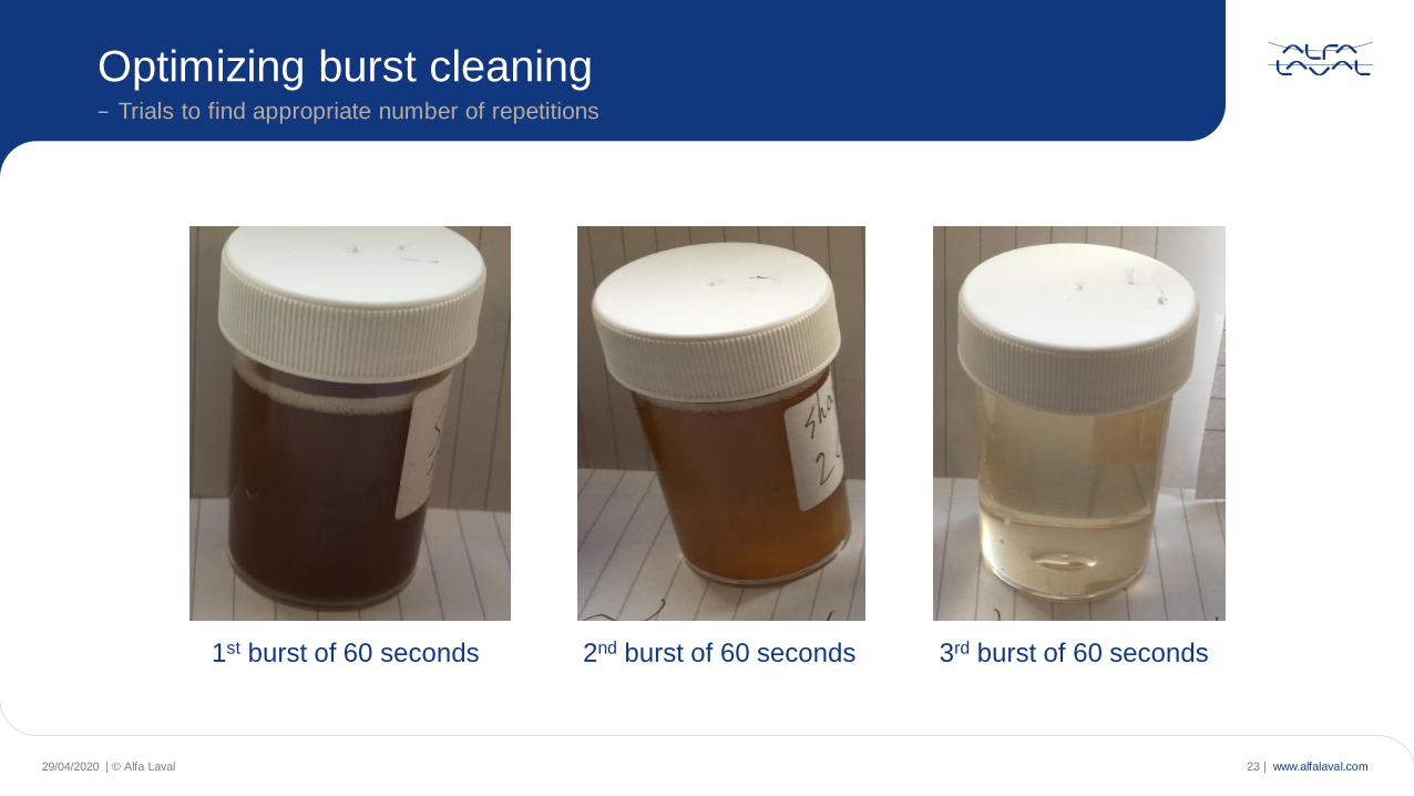
Optimizing burst cleaning− Trials to find appropriate number of repetitions
1st burst of 60 seconds 2nd burst of 60 seconds 3rd burst of 60 seconds
www.alfalaval.com29/04/2020 | © Alfa Laval 24 |
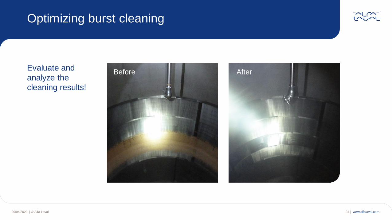
Optimizing burst cleaning
Before AfterEvaluate and
analyze the
cleaning results!
www.alfalaval.com29/04/2020 | © Alfa Laval 25 |
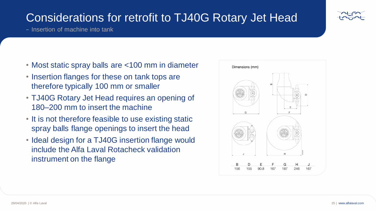
• Most static spray balls are <100 mm in diameter
• Insertion flanges for these on tank tops are
therefore typically 100 mm or smaller
• TJ40G Rotary Jet Head requires an opening of
180–200 mm to insert the machine
• It is not therefore feasible to use existing static
spray balls flange openings to insert the head
• Ideal design for a TJ40G insertion flange would
include the Alfa Laval Rotacheck validation
instrument on the flange
Considerations for retrofit to TJ40G Rotary Jet Head− Insertion of machine into tank
www.alfalaval.com
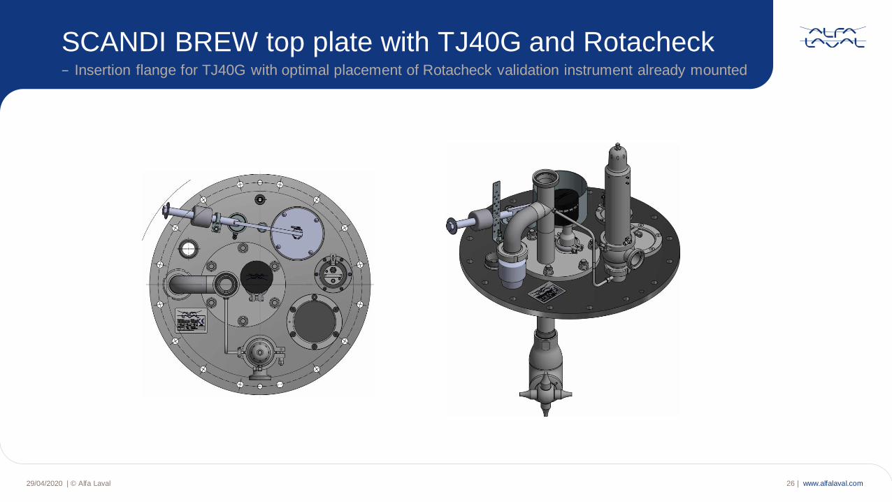
SCANDI BREW top plate with TJ40G and Rotacheck− Insertion flange for TJ40G with optimal placement of Rotacheck validation instrument already mounted
29/04/2020 | © Alfa Laval 26 |
www.alfalaval.com
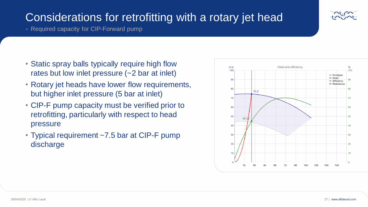
Considerations for retrofitting with a rotary jet head− Required capacity for CIP-Forward pump
29/04/2020 | © Alfa Laval 27 |
• Static spray balls typically require high flow
rates but low inlet pressure (~2 bar at inlet)
• Rotary jet heads have lower flow requirements,
but higher inlet pressure (5 bar at inlet)
• CIP-F pump capacity must be verified prior to
retrofitting, particularly with respect to head
pressure
• Typical requirement ~7.5 bar at CIP-F pump
discharge
www.alfalaval.com
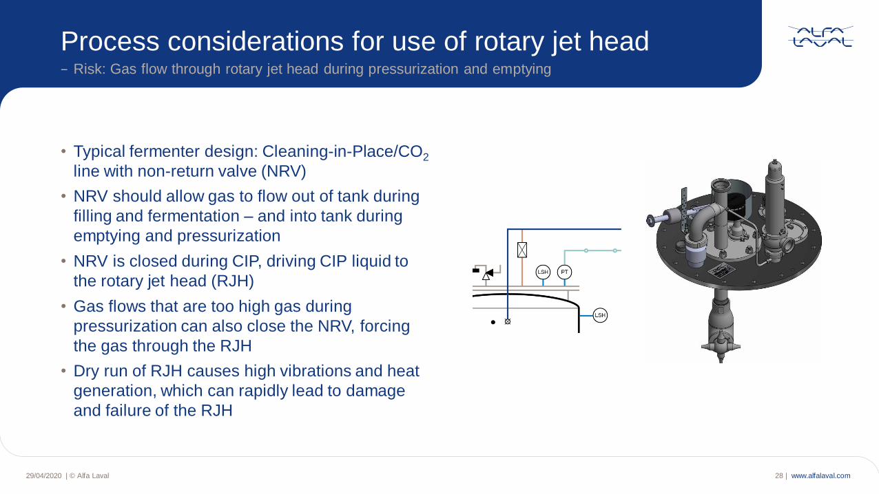
Process considerations for use of rotary jet head− Risk: Gas flow through rotary jet head during pressurization and emptying
29/04/2020 | © Alfa Laval 28 |
• Typical fermenter design: Cleaning-in-Place/CO2
line with non-return valve (NRV)
• NRV should allow gas to flow out of tank during
filling and fermentation – and into tank during
emptying and pressurization
• NRV is closed during CIP, driving CIP liquid to
the rotary jet head (RJH)
• Gas flows that are too high gas during
pressurization can also close the NRV, forcing
the gas through the RJH
• Dry run of RJH causes high vibrations and heat
generation, which can rapidly lead to damage
and failure of the RJH
www.alfalaval.com29/04/2020 | © Alfa Laval 29 |
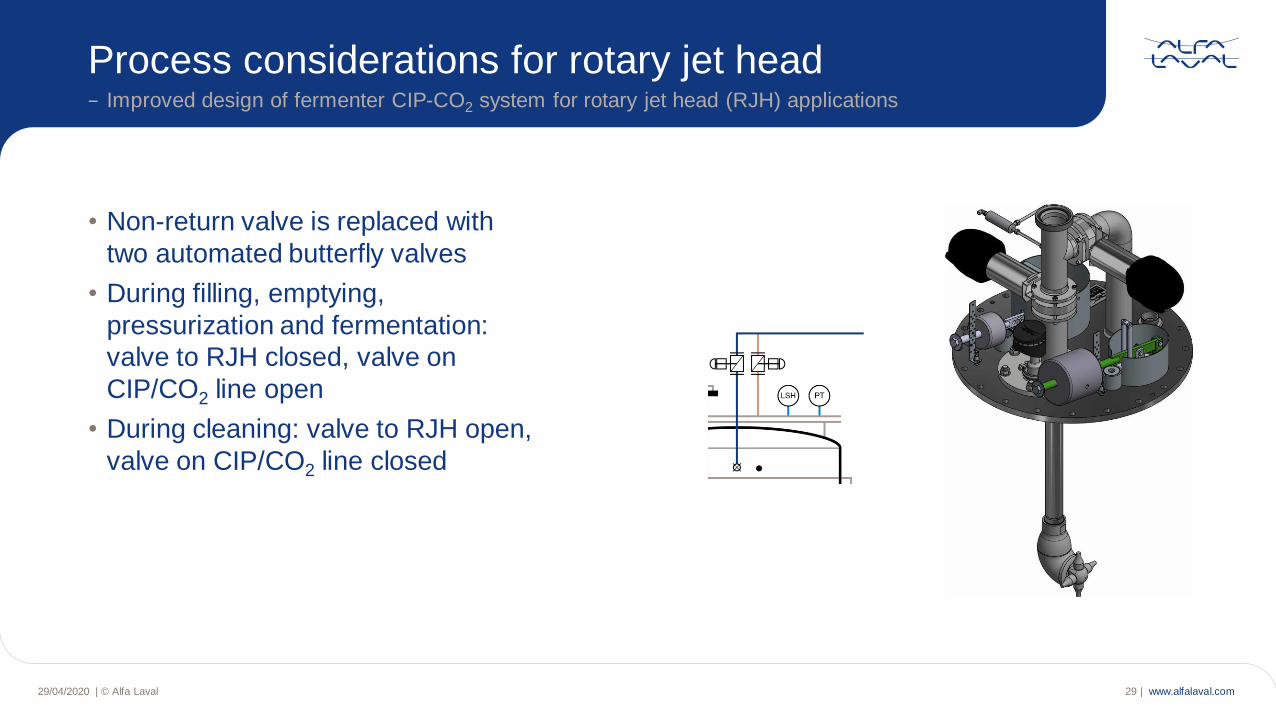
• Non-return valve is replaced with
two automated butterfly valves
• During filling, emptying,
pressurization and fermentation:
valve to RJH closed, valve on
CIP/CO2 line open
• During cleaning: valve to RJH open,
valve on CIP/CO2 line closed
Process considerations for rotary jet head− Improved design of fermenter CIP-CO2 system for rotary jet head (RJH) applications
www.alfalaval.com29/04/2020 | © Alfa Laval 30 |
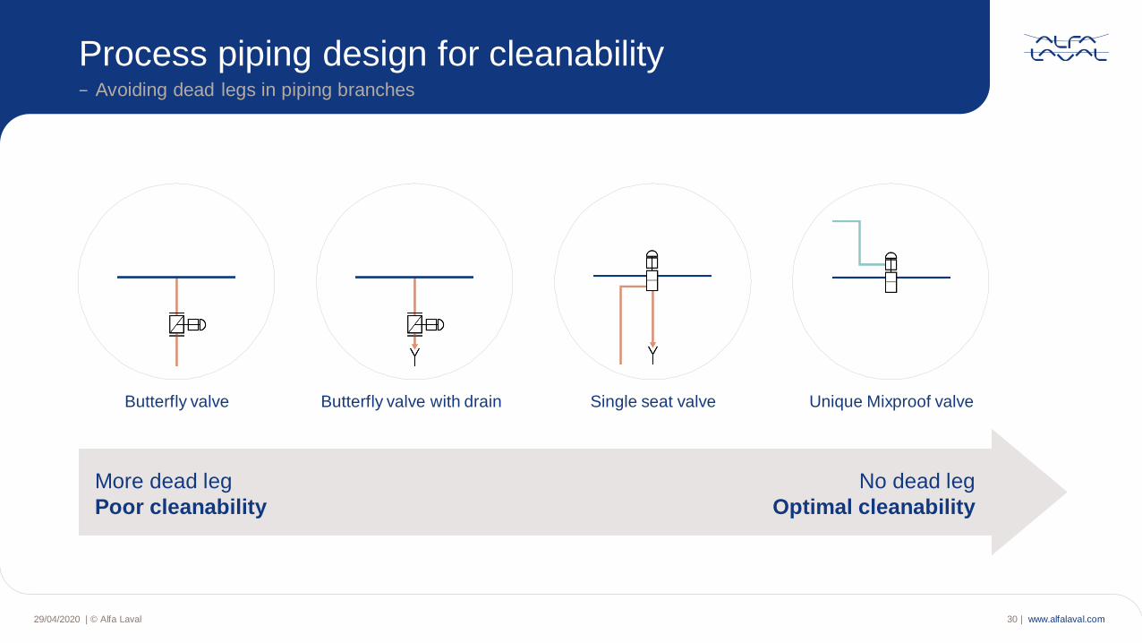
Process piping design for cleanability− Avoiding dead legs in piping branches
More dead leg
Poor cleanability
No dead leg
Optimal cleanability
Butterfly valve Butterfly valve with drain Single seat valve Unique Mixproof valve
www.alfalaval.com
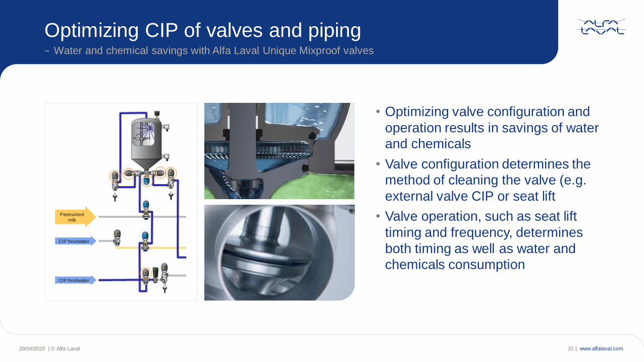
Optimizing CIP of valves and piping− Water and chemical savings with Alfa Laval Unique Mixproof valves
29/04/2020 | © Alfa Laval 31 |
• Optimizing valve configuration and
operation results in savings of water
and chemicals
• Valve configuration determines the
method of cleaning the valve (e.g.
external valve CIP or seat lift
• Valve operation, such as seat lift
timing and frequency, determines
both timing as well as water and
chemicals consumption
Pasteurized
milk
CIP freshwater
CIP freshwater
www.alfalaval.com29/04/2020 | © Alfa Laval 32 |
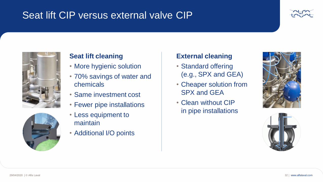
Seat lift CIP versus external valve CIP
External cleaning
• Standard offering
(e.g., SPX and GEA)
• Cheaper solution from
SPX and GEA
• Clean without CIP
in pipe installations
Seat lift cleaning
• More hygienic solution
• 70% savings of water and
chemicals
• Same investment cost
• Fewer pipe installations
• Less equipment to
maintain
• Additional I/O points
www.alfalaval.com29/04/2020 | © Alfa Laval 33 |
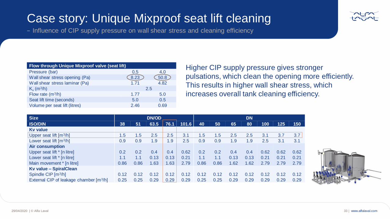
Case story: Unique Mixproof seat lift cleaning− Influence of CIP supply pressure on wall shear stress and cleaning efficiency
Higher CIP supply pressure gives stronger
pulsations, which clean the opening more efficiently.
This results in higher wall shear stress, which
increases overall tank cleaning efficiency.
Flow through Unique Mixproof valve (seat lift)
Pressure (bar) 0.5 4.0
Wall shear stress opening (Pa) 8.23 50.8
Wall shear stress laminar (Pa) 1.71 4.82
Kv (m3/h) 2.5
Flow rate (m3/h) 1.77 5.0
Seat lift time (seconds) 5.0 0.5
Volume per seat lift (litres) 2.46 0.69
Size DN/OD DN
ISO/DIN 38 51 63.5 76.1 101.6 40 50 65 80 100 125 150
Kv value
Upper seat lift [m3/h] 1.5 1.5 2.5 2.5 3.1 1.5 1.5 2.5 2.5 3.1 3.7 3.7
Lower seat lift [m3/h] 0.9 0.9 1.9 1.9 2.5 0.9 0.9 1.9 1.9 2.5 3.1 3.1
Air consumption
Upper seat lift * [n litre] 0.2 0.2 0.4 0.4 0.62 0.2 0.2 0.4 0.4 0.62 0.62 0.62
Lower seat lift * [n litre] 1.1 1.1 0.13 0.13 0.21 1.1 1.1 0.13 0.13 0.21 0.21 0.21
Main movement * [n litre] 0.86 0.86 1.63 1.63 2.79 0.86 0.86 1.62 1.62 2.79 2.79 2.79
Kv value – SpiralClean
Spindle CIP [m3/h] 0.12 0.12 0.12 0.12 0.12 0.12 0.12 0.12 0.12 0.12 0.12 0.12
External CIP of leakage chamber [m3/h] 0.25 0.25 0.29 0.29 0.29 0.25 0.25 0.29 0.29 0.29 0.29 0.29
www.alfalaval.com
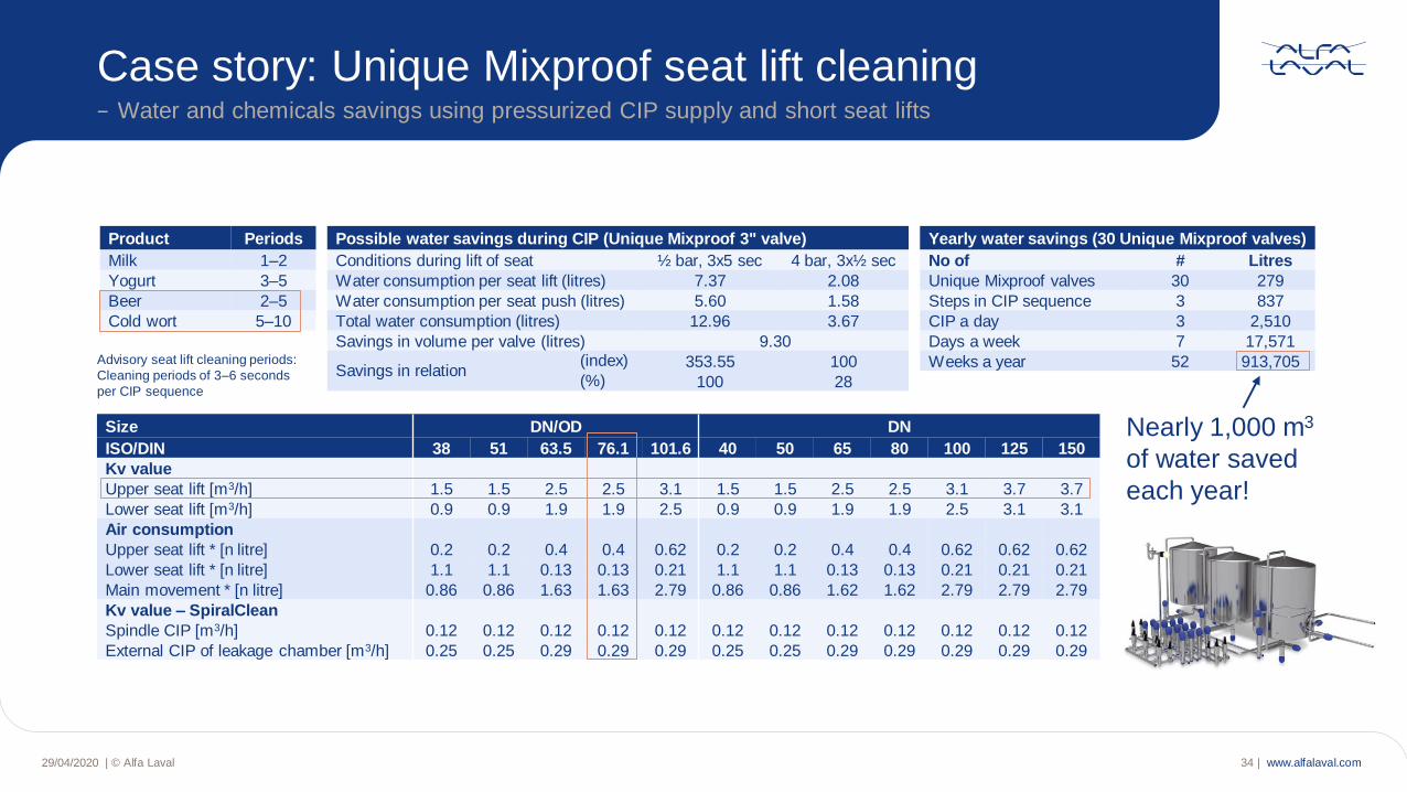
Product Periods
Milk 1–2
Yogurt 3–5
Beer 2–5
Cold wort 5–10
Yearly water savings (30 Unique Mixproof valves)
No of # Litres
Unique Mixproof valves 30 279
Steps in CIP sequence 3 837
CIP a day 3 2,510
Days a week 7 17,571
Weeks a year 52 913,705
29/04/2020 | © Alfa Laval 34 |
Case story: Unique Mixproof seat lift cleaning− Water and chemicals savings using pressurized CIP supply and short seat lifts
Nearly 1,000 m3
of water saved
each year!
Advisory seat lift cleaning periods:
Cleaning periods of 3–6 seconds
per CIP sequence
Size DN/OD DN
ISO/DIN 38 51 63.5 76.1 101.6 40 50 65 80 100 125 150
Kv value
Upper seat lift [m3/h] 1.5 1.5 2.5 2.5 3.1 1.5 1.5 2.5 2.5 3.1 3.7 3.7
Lower seat lift [m3/h] 0.9 0.9 1.9 1.9 2.5 0.9 0.9 1.9 1.9 2.5 3.1 3.1
Air consumption
Upper seat lift * [n litre] 0.2 0.2 0.4 0.4 0.62 0.2 0.2 0.4 0.4 0.62 0.62 0.62
Lower seat lift * [n litre] 1.1 1.1 0.13 0.13 0.21 1.1 1.1 0.13 0.13 0.21 0.21 0.21
Main movement * [n litre] 0.86 0.86 1.63 1.63 2.79 0.86 0.86 1.62 1.62 2.79 2.79 2.79
Kv value – SpiralClean
Spindle CIP [m3/h] 0.12 0.12 0.12 0.12 0.12 0.12 0.12 0.12 0.12 0.12 0.12 0.12
External CIP of leakage chamber [m3/h] 0.25 0.25 0.29 0.29 0.29 0.25 0.25 0.29 0.29 0.29 0.29 0.29
Possible water savings during CIP (Unique Mixproof 3" valve)
Conditions during lift of seat ½ bar, 3x5 sec 4 bar, 3x½ sec
Water consumption per seat lift (litres) 7.37 2.08
Water consumption per seat push (litres) 5.60 1.58
Total water consumption (litres) 12.96 3.67
Savings in volume per valve (litres) 9.30
Savings in relation (index) 353.55 100(%) 100 28
www.alfalaval.com29/04/2020 | © Alfa Laval 35 |
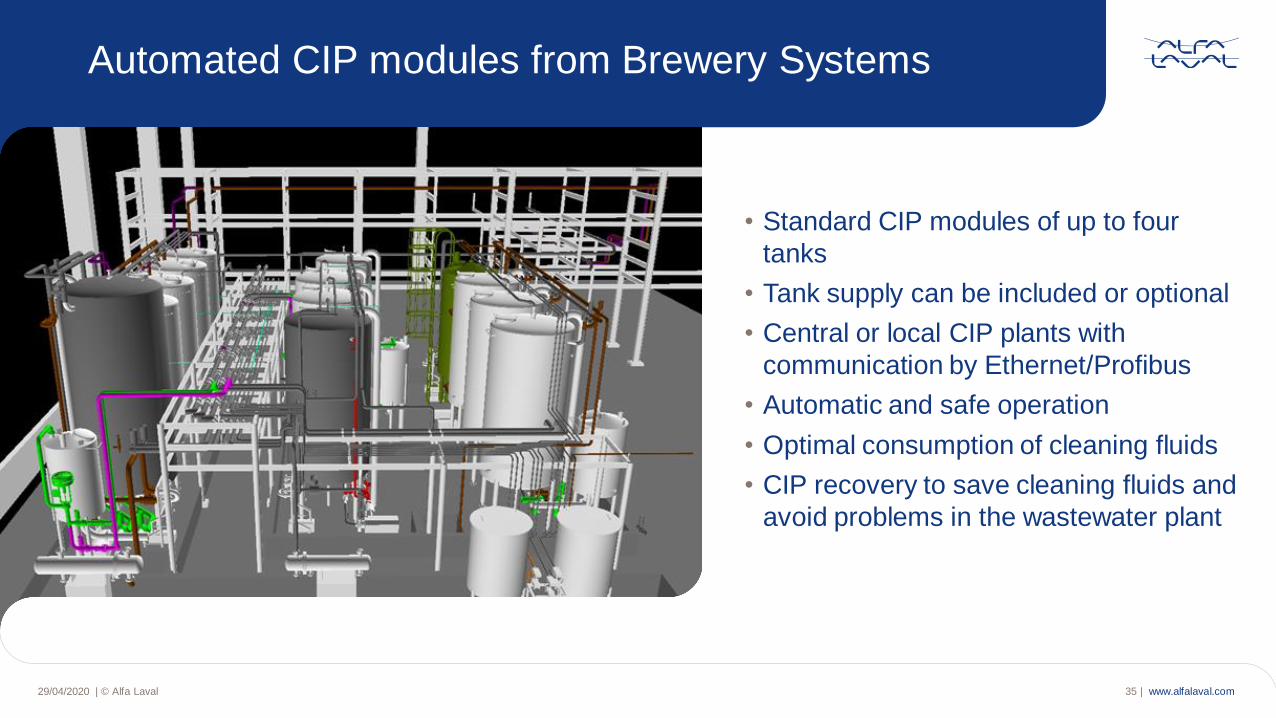
• Standard CIP modules of up to four
tanks
• Tank supply can be included or optional
• Central or local CIP plants with
communication by Ethernet/Profibus
• Automatic and safe operation
• Optimal consumption of cleaning fluids
• CIP recovery to save cleaning fluids and
avoid problems in the wastewater plant
Automated CIP modules from Brewery Systems
www.alfalaval.com29/04/2020 | © Alfa Laval 36 |
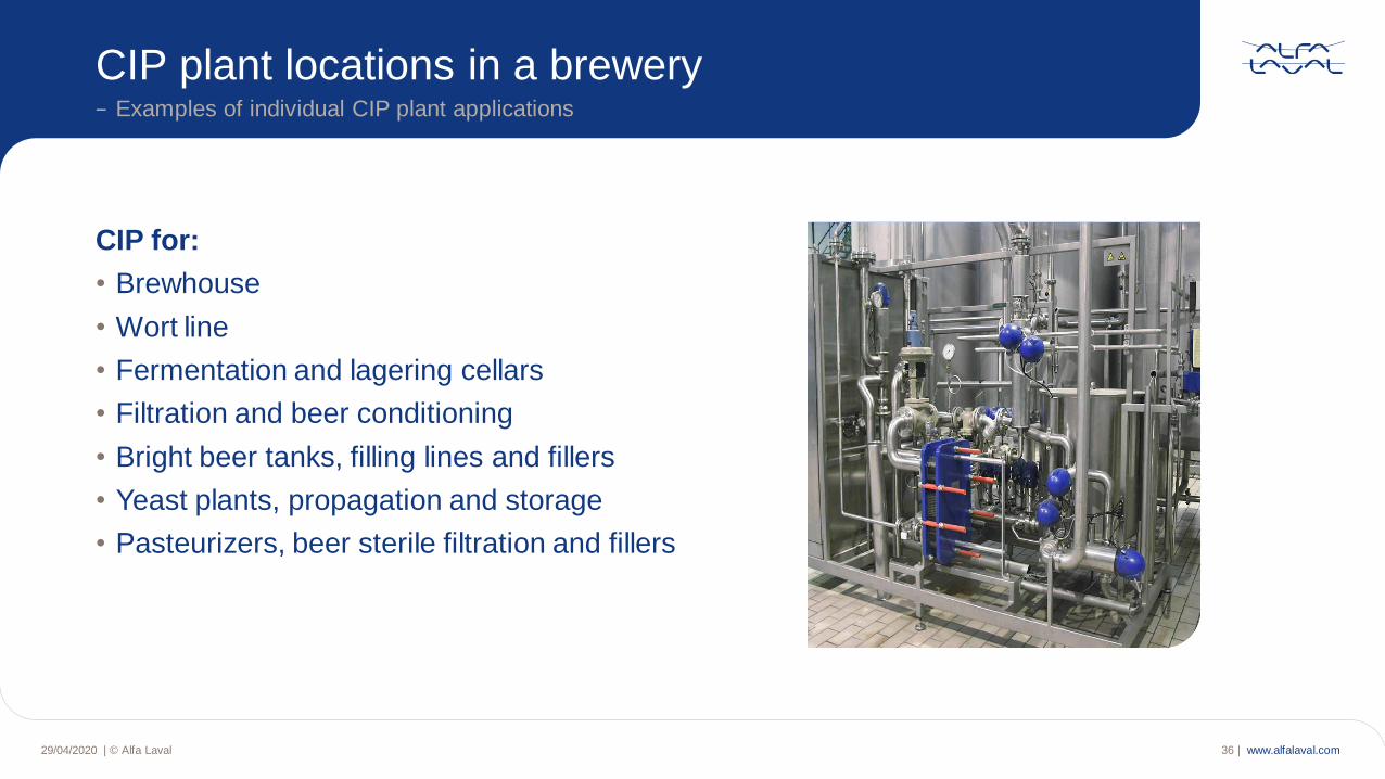
CIP for:
• Brewhouse
• Wort line
• Fermentation and lagering cellars
• Filtration and beer conditioning
• Bright beer tanks, filling lines and fillers
• Yeast plants, propagation and storage
• Pasteurizers, beer sterile filtration and fillers
CIP plant locations in a brewery− Examples of individual CIP plant applications
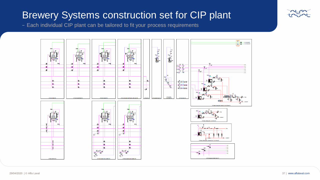
www.alfalaval.com29/04/2020 | © Alfa Laval 37 |
Brewery Systems construction set for CIP plant− Each individual CIP plant can be tailored to fit your process requirements
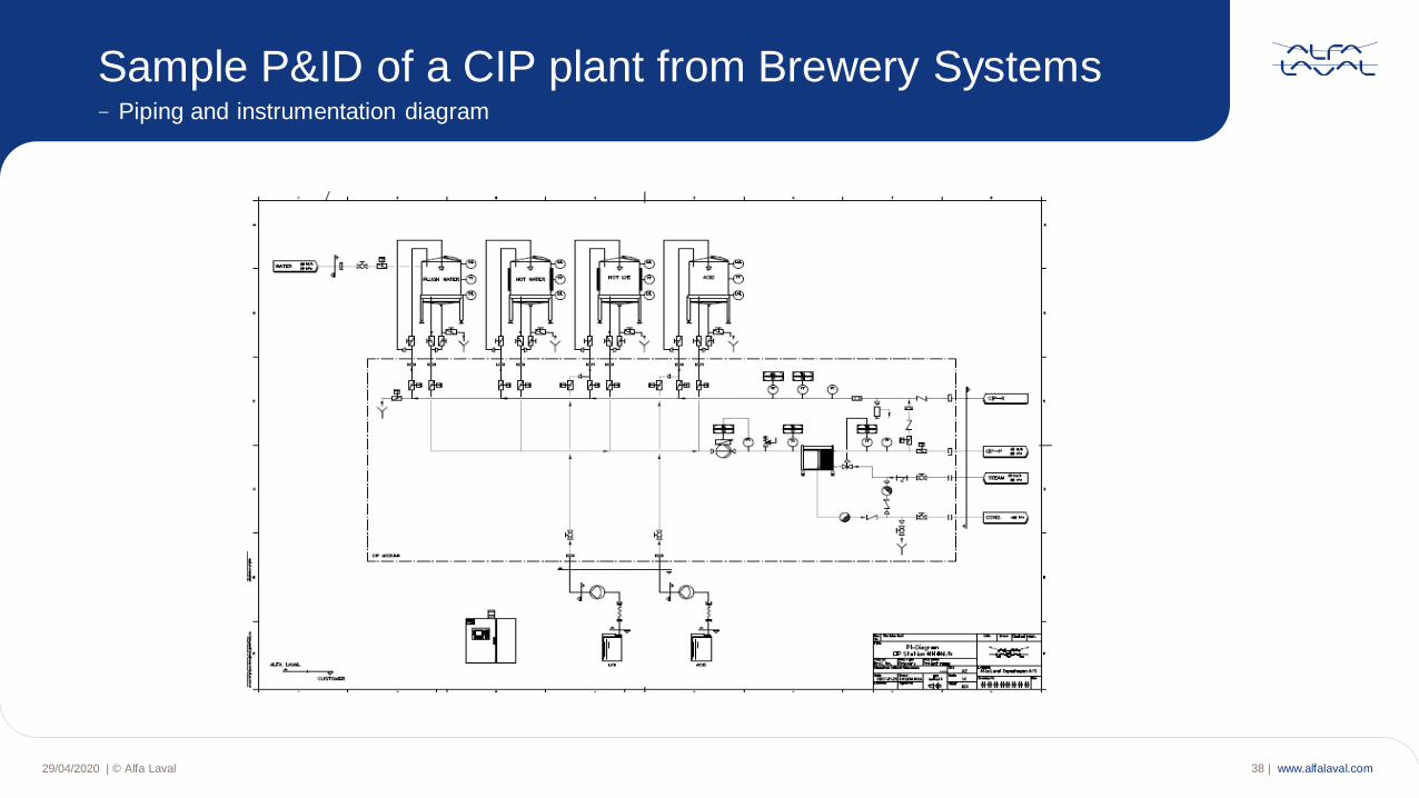
www.alfalaval.com29/04/2020 | © Alfa Laval 38 |
Sample P&ID of a CIP plant from Brewery Systems− Piping and instrumentation diagram
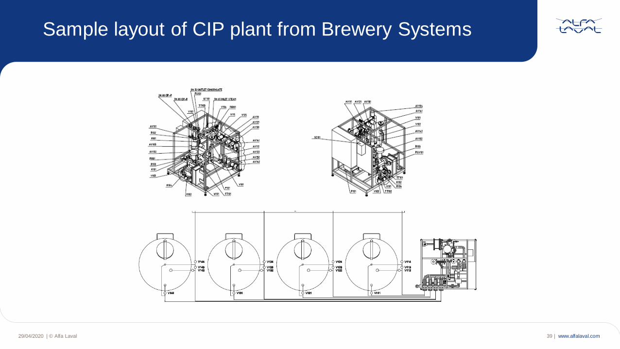
www.alfalaval.com29/04/2020 | © Alfa Laval 39 |
Sample layout of CIP plant from Brewery Systems
www.alfalaval.com29/04/2020 | © Alfa Laval 40 |
Dry hopping II
Learn how you can streamline and
optimize your dry-hopping processes
Webinars for brewers− Upcoming webinar 25 June, 2020
Dry hopping II
Webinar 25 June, 2020
www.alfalaval.com29/04/2020 | © Alfa Laval 41 |
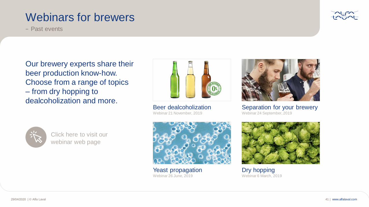
Our brewery experts share their
beer production know-how.
Choose from a range of topics
– from dry hopping to
dealcoholization and more.
Webinars for brewers− Past events
Yeast propagationWebinar 26 June, 2019
Dry hopping Webinar 6 March, 2019
Separation for your brewery Webinar 24 September, 2019
Beer dealcoholization Webinar 21 November, 2019
Click here to visit our
webinar web page
www.alfalaval.com| © Alfa Laval 42 |29/04/2020
Thank you for your attention!− Any questions?
www.alfalaval.com


