Preparation and characterization of oriented MAPO-39membranes
Lisa Washmon-Kriel, Kenneth J. Balkus Jr. *
Department of Chemistry, University of Texas at Dallas, Richardson, TX 75083-0688, USA
Received 22 September 1999; accepted 16 November 1999
Abstract
Thin ®lms of MAPO-39, a small pore (4 �A) magnesium aluminophosphate molecular sieve (ATN topology), have
been prepared via pulsed laser deposition (PLD) for the ®rst time. Laser ablation of MAPO-39 onto porous metal
substrates followed by a post-hydrothermal treatment of the PLD ®lm results in oriented crystalline MAPO-39
membranes. The MAPO-39 crystals grow with pores oriented primarily normal to the porous metal substrate. De-
composition of the template provides access to the membrane pores. Preliminary results for the separation of water/
alcohol mixtures using the MAPO-39 oriented membrane are described. Selective permeation of water was observed in
all the cases. Ó 2000 Elsevier Science B.V. All rights reserved.
Keywords: MAPO-39; Laser ablation; Membranes; Molecular sieve
1. Introduction
Microporous molecular sieve membranes o�ersize and shape selectivity in molecular dimensions[1]. The uniform and sometimes oriented pores ofthe molecular sieve membranes make them at-tractive for use in separations as well as emergingapplications in catalysis and chemical sensors. Theadvantages of molecular sieve membranes includethe uniformity of pore size, chemical stability andthermal stability. Molecular sieves may also bemodi®ed to tailor the di�usion and absorptioncharacteristics of the material [2].
There are a variety of methods that can be em-ployed in the preparation of molecular sieve ®lms,
possessing both random and preferred orientation.Free-standing and supported ®lms have been pre-pared. However, the fragile nature of the nanopor-ous oxide membranes generally dictates themechanically robust substrate. The most popularmethod for fabricating molecular sieve ®lms hasbeen the seeded growth approach [3±13]. In thiscase, nanoseeds of the target zeolite are depositedfrom a solution onto a substrate that is typically ¯at.The seed crystals are then subjected to a synthesisgel in an e�ort to grow a thick continuous ®lm.
There has been some success in the preparationof oriented molecular sieve ®lms by the secondarygrowth of the precursor layers consisting of na-nometer-sized crystals of Zeolite A [3] and silica-lite-1 [7]. In these examples, the seed layers wereapplied onto a glass or polished alumina supportby dip coating in an aqueous suspension of thezeolite nanocrystals. It has been reported that this
Microporous and Mesoporous Materials 38 (2000) 107±121
www.elsevier.nl/locate/micromeso
* Corresponding author. Fax: +1-972-883-2925.
E-mail address: [email protected] (K.J. Balkus Jr.).
1387-1811/00/$ - see front matter Ó 2000 Elsevier Science B.V. All rights reserved.
PII: S 1 3 8 7 - 1 8 1 1 ( 9 9 ) 0 0 2 8 6 - 3
method circumvents the zeolite nucleation step dueto the presence of seed crystals and provides somecontrol of the ®lm microstructure, enhances re-producibility, and scalability [8]. This approachand the related techniques have resulted in ori-ented ®lms of zeolites having the MFI [7,14±18],LTA [9,19], and AFI [20] topologies.
We have reported a method for the preparationof molecular sieve thin ®lms and membranes usingpulsed laser deposition (PLD) [21±28]. The laserdeposition technique has, recently, yielded orient-ed ®lms and membranes of the microporous ma-terials UTD-1 [21,29,30] and Ti UTD-1 [31], andmesoporous MCM-41 [32]. The PLD method in-volves the deposition of a densely packed layer ofmolecular sieve nanoparticles onto a variety ofsubstrates via laser ablation. The laser deposited
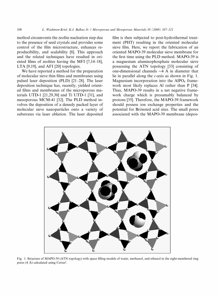
®lm is then subjected to post-hydrothermal treat-ment (PHT) resulting in the oriented molecularsieve ®lm. Here, we report the fabrication of anoriented MAPO-39 molecular sieve membrane forthe ®rst time using the PLD method. MAPO-39 isa magnesium aluminophosphate molecular sievepossessing the ATN topology [33] consisting ofone-dimensional channels �4 �A in diameter thatlie in parallel along the c-axis as shown in Fig. 1.Magnesium incorporation into the AlPO4 frame-work most likely replaces Al rather than P [34].Thus, MAPO-39 results in a net negative frame-work charge which is presumably balanced byprotons [35]. Therefore, the MAPO-39 frameworkshould possess ion exchange properties and thepotential for Br�onsted acid sites. The small poresassociated with the MAPO-39 membrane (depos-
Fig. 1. Structure of MAPO-39 (ATN topology) with space ®lling models of water, methanol, and ethanol in the eight-membered ring
pores (4 �A) calculated using Cerius2.
108 L. Washmon-Kriel, K.J. Balkus Jr. / Microporous and Mesoporous Materials 38 (2000) 107±121
ited on a porous stainless steel frit) could be uti-lized in the separation of a variety of small mole-cules. Preliminary results for the separation ofwater and lower alcohols such as methanol andethanol are presented.
2. Experimental
2.1. MAPO-39 synthesis
MAPO-39 was synthesized hydrothermally us-ing two previously reported methods, a 96 h(Method 1) [36] and a 12 h (Method 2) synthesis[37]. For Method 1, a gel with the molar compo-sition 1.2Pr2NH : 0.80MgO : 0.8Al2O3 : 1.02P2O5 :41H2O was prepared by ®rst adding 1.6 g boeh-mite (Vista) to 9.0 g H2O in a 50 ml beaker. Asolution of magnesium acetate was prepared sep-arately by dissolving 1.12 g of Mg(C(O)OCH3)2
(Aldrich) in 5.5 g of H2O followed by the additionto the alumina/water mixture with continu-ous stirring. Subsequently, 4.0 g of 85% H3PO4
(Fisher) was added to the above mixture at a rateof approximately 1 ml/min followed by stirring for15 min. Finally, 2.24 ml of dipropylamine (Ald-rich) was added dropwise and then stirred for 15min. The resulting white cloudy solution (pH 3.9)was transferred to a 23 ml Te¯on-lined autoclave(Parr) and heated under static conditions at 150°Cfor 96 h. The Method 2 synthesis involved dis-solving 2.5 g boehmite (Vista) in a solution of 4.6 gH3PO4 (Fisher) and 9.3 g H2O to yield a white gel.Separately, 0.72 g of magnesium acetate (Aldrich)was dissolved in 2.5 g of deionized water andadded to the above gel. The resulting gel wascombined with 2.0 g of dipropylamine (Aldrich)and stirred until it became homogeneous. The gelgradually became thinner and clearer but was stillwhite. The resulting synthesis gel of molar ratio0.87Pr2NH : 0.22MgO : 1.05Al2O3 : 1.02P2O5 : 28-H2O had a pH of 3.3. The gel was placed in aTe¯on-lined autoclave (Parr) and heated at 150°Cfor 4±24 h. Following each synthesis, the reactorwas cooled, and the white MAPO-39 crystals col-lected by vacuum ®ltration, washed with deionizedwater and air-dried at room temperature.
2.2. Film deposition
As-synthesized MAPO-39 (Method 1) waspressed into a free-standing 2.5 cm diameter targetfor laser ablation experiments. The target materialwas placed in a controlled atmosphere chamber aspreviously described [38]. Laser depositions wereperformed using a Lumonics HyperEX400 14 nslaser pulse operating at 248 nm (KrF*) with afrequency of 10 Hz. The laser ¯ux was measuredwith a Scientech pyroelectric head (Model 380402)and was found to range from 90±160 mJ/pulse.The laser radiation was rastered across theMAPO-39 target using a computer controlledmirror (Oriel) to provide a continually fresh sur-face. The laser beam was focused onto a spot ofsize 0.001 cm2 upon entering the ablation chamber.The substrates were heated in vacuo at �300°C toremove any absorbed organics prior to laser ab-lation. The porous stainless steel disk substrates,6 mm� 1:5 mm, having a pore size of 0.5 lm(Mott Metallurgical) were heated during laser de-position to temperatures of 175±250°C. Typicallaser ablation conditions were as follows: laserpower, 90±160 mJ/pulse; repetition rate, 10 Hz;substrate temperature, 150±225°C, and back-ground oxygen pressure, 150±225 mTorr whichprovided a deposition rate of �39 nm/min.
2.3. Post-hydrothermal treatment
Laser deposited ®lms were subjected to a post-hydrothermal treatment in which the sample wasplaced with the ablated ®lm side down at �60°angle inside the Te¯on-lined reactor. A fresh syn-thesis gel (Method 2) was added to the reactor andheated statically at 150°C for 4±24 h. To preventdepositing MAPO-39 crystals in the metal sub-strate pores, the nonablated side (back side) wasprotected by covering with Te¯on tape during thepost-hydrothermal treatment. The reorganized®lm was washed with deionized water and air-dried at room temperature. The crystallinity andmorphology of the as-synthesized MAPO-39 andthe molecular sieve membranes were characterizedby powder X-ray di�raction (XRD) using a Scin-tag XDS 2000 di�ractometer with Cu Ka radiationand scanning electron microscopy using a Phillips
L. Washmon-Kriel, K.J. Balkus Jr. / Microporous and Mesoporous Materials 38 (2000) 107±121 109
XL60 microscope, respectively. Bulk MAPO-39and PLD ®lms were characterized by FTIR spec-troscopy using a Nicolet Avatar 360 spectrometer.Additionally, all products were subjected to energydispersive X-ray spectroscopy using PhillipsEDAX PV 9800 for Mg : Al : P ratio determina-tion.
2.4. Pervaporation experiments
Reorganized MAPO-39 membranes were heat-ed at 350°C in an oxygen stream for 3 h to de-compose the organic template, thus providingaccess to the one-dimensional pore system. Themembrane, supported on stainless steel, wasmounted on a coarse glass frit support in a 1 cmdiameter glass tube (Ace Glass). The membranewas secured and sealed around the edges usingepoxy cement (Devcon 2-Ton White). The epoxywas allowed to set and dry in air, overnight. Thefeed, consisting of �1.5 ml of a 1:1 (v:v) mixture ofwater and methanol or water and ethanol, wasplaced upstream at atmospheric pressure. Thedownstream-side pressure was maintained at ap-proximately 30 lm and the permeate was con-densed in a liquid nitrogen trap and, subsequently,analyzed by gas chromatography (Shimadzu GC-8A) using a Supelco 2 meter 20% DC710 packedcolumn.
3. Results and discussion
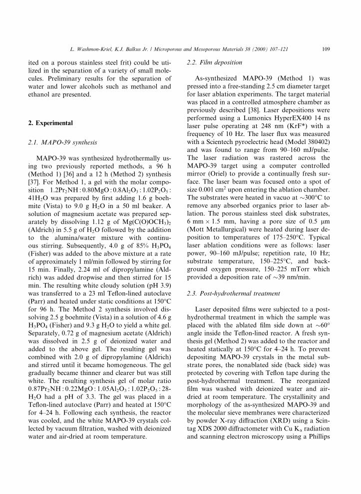
Highly crystalline MAPO-39 was prepared as asingle phase by the Method 1 synthesis [36] asevidenced by the powder XRD pattern shown inFig. 2. There have been only a few studies dealingwith MAPO-39 [34±37,39,40]. Nevertheless, thepowder pattern is in very good agreement withthe literature data except for intensities. The as-synthesized MAPO-39 material obtained fromMethod 1 shows the (1 3 0)=(3 1 0) re¯ection atd� 4.30 �A and is the most intense, in contrast toa report that the (1 2 1)=(2 1 1) re¯ection has 100%peaks [36]. Methods 1 and 2, and the post-hydrothermal treatment lead to as-synthesizedMAPO-39 materials having unit-cell volumes of923, 937, and 937 �A3, respectively. These volumescorrespond well to the published values of 923 and938 �A3 for Methods 1 [36] and 2 [37], respectively.The crystalline MAPO-39 unit cell is also consis-tent with magnesium incorporation into the mo-lecular sieve. Methods 1 and 2 yield MAPO-39with Al : Mg ratios of 4.30 and 5.08, respectively.Single crystal X-ray di�raction results for MAPO-39 having the chemical formula Al7MgHP8O32
indicate an Al : Mg ratio of 6.47 [35]. Thus, onecannot rule out the presence of extra frameworkmagnesium in MAPO-39 preparations.
The SEM image in Fig. 3(a) reveals primarilylarge aggregates (20±50 lm) of platelet shaped
Fig. 2. Powder XRD pattern of MAPO-39 prepared by the Method 1 synthesis.
110 L. Washmon-Kriel, K.J. Balkus Jr. / Microporous and Mesoporous Materials 38 (2000) 107±121
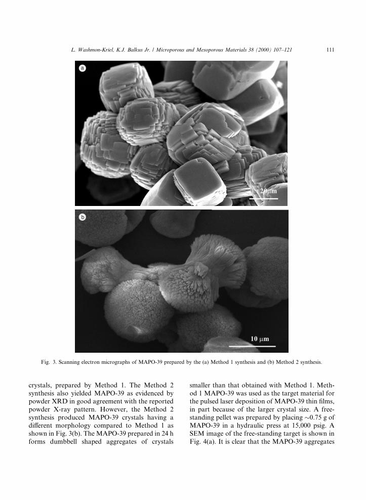
crystals, prepared by Method 1. The Method 2synthesis also yielded MAPO-39 as evidenced bypowder XRD in good agreement with the reportedpowder X-ray pattern. However, the Method 2synthesis produced MAPO-39 crystals having adi�erent morphology compared to Method 1 asshown in Fig. 3(b). The MAPO-39 prepared in 24 hforms dumbbell shaped aggregates of crystals
smaller than that obtained with Method 1. Meth-od 1 MAPO-39 was used as the target material forthe pulsed laser deposition of MAPO-39 thin ®lms,in part because of the larger crystal size. A free-standing pellet was prepared by placing �0.75 g ofMAPO-39 in a hydraulic press at 15,000 psig. ASEM image of the free-standing target is shown inFig. 4(a). It is clear that the MAPO-39 aggregates
Fig. 3. Scanning electron micrographs of MAPO-39 prepared by the (a) Method 1 synthesis and (b) Method 2 synthesis.
L. Washmon-Kriel, K.J. Balkus Jr. / Microporous and Mesoporous Materials 38 (2000) 107±121 111
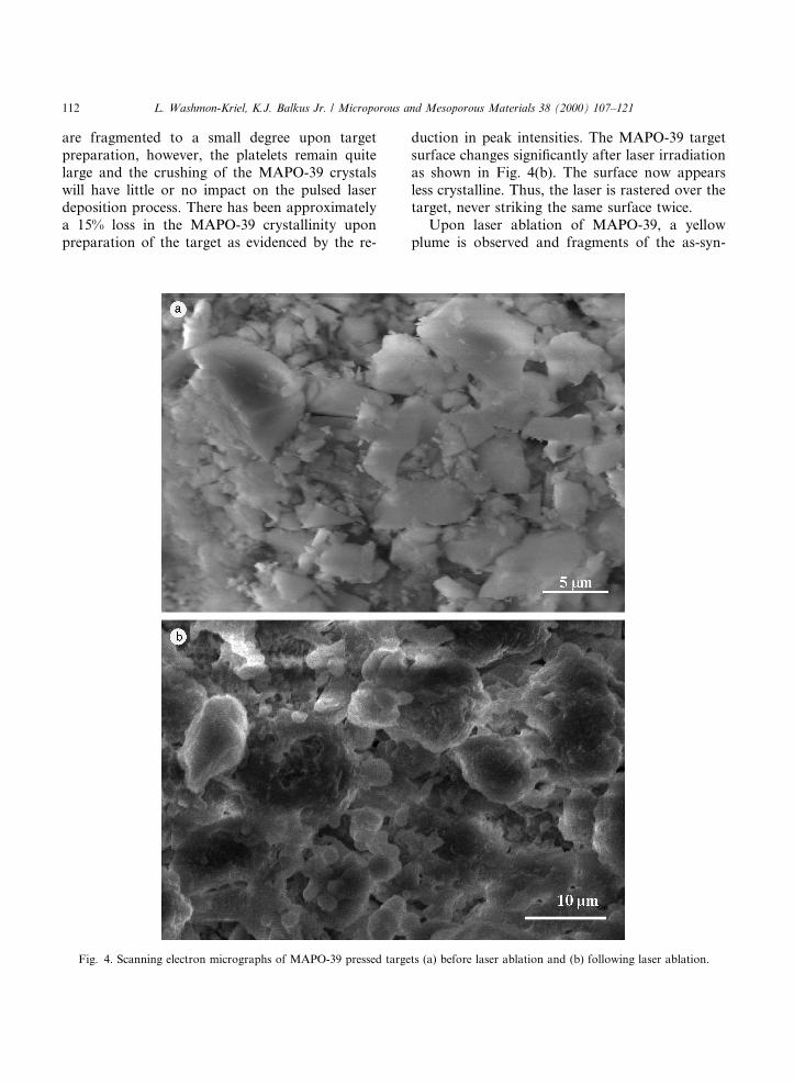
are fragmented to a small degree upon targetpreparation, however, the platelets remain quitelarge and the crushing of the MAPO-39 crystalswill have little or no impact on the pulsed laserdeposition process. There has been approximatelya 15% loss in the MAPO-39 crystallinity uponpreparation of the target as evidenced by the re-
duction in peak intensities. The MAPO-39 targetsurface changes signi®cantly after laser irradiationas shown in Fig. 4(b). The surface now appearsless crystalline. Thus, the laser is rastered over thetarget, never striking the same surface twice.
Upon laser ablation of MAPO-39, a yellowplume is observed and fragments of the as-syn-
Fig. 4. Scanning electron micrographs of MAPO-39 pressed targets (a) before laser ablation and (b) following laser ablation.
112 L. Washmon-Kriel, K.J. Balkus Jr. / Microporous and Mesoporous Materials 38 (2000) 107±121
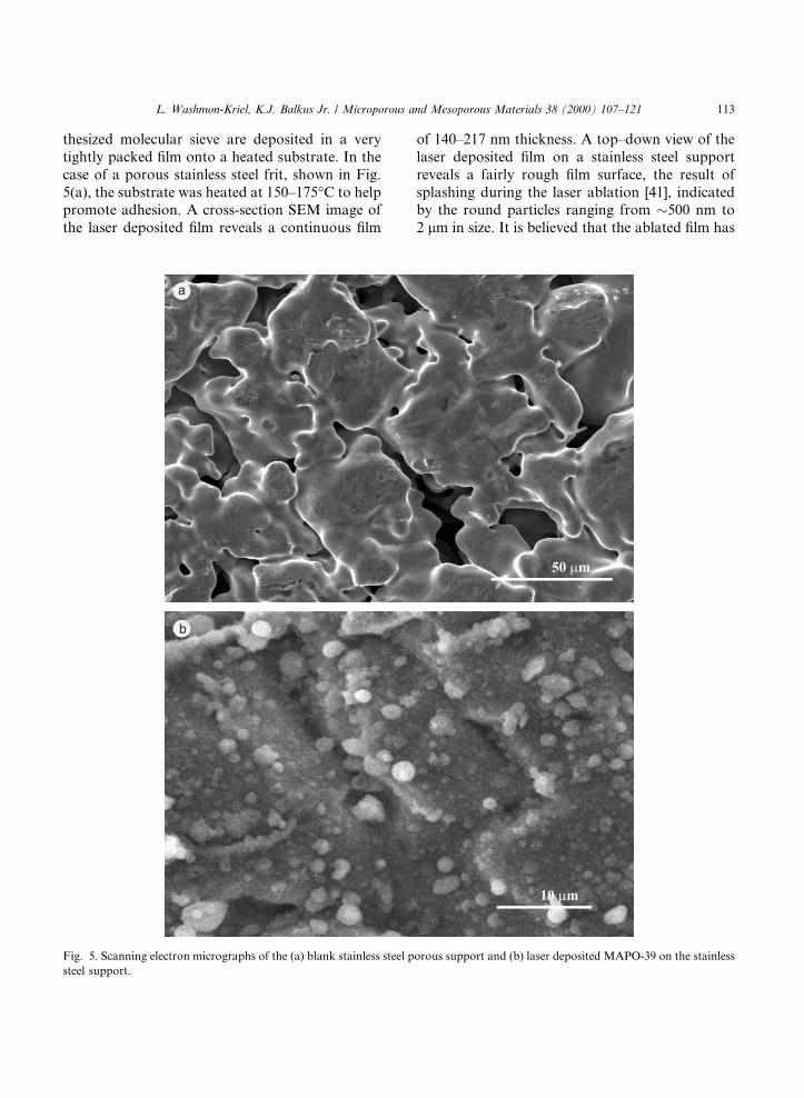
thesized molecular sieve are deposited in a verytightly packed ®lm onto a heated substrate. In thecase of a porous stainless steel frit, shown in Fig.5(a), the substrate was heated at 150±175°C to helppromote adhesion. A cross-section SEM image ofthe laser deposited ®lm reveals a continuous ®lm
of 140±217 nm thickness. A top±down view of thelaser deposited ®lm on a stainless steel supportreveals a fairly rough ®lm surface, the result ofsplashing during the laser ablation [41], indicatedby the round particles ranging from �500 nm to2 lm in size. It is believed that the ablated ®lm has
Fig. 5. Scanning electron micrographs of the (a) blank stainless steel porous support and (b) laser deposited MAPO-39 on the stainless
steel support.
L. Washmon-Kriel, K.J. Balkus Jr. / Microporous and Mesoporous Materials 38 (2000) 107±121 113
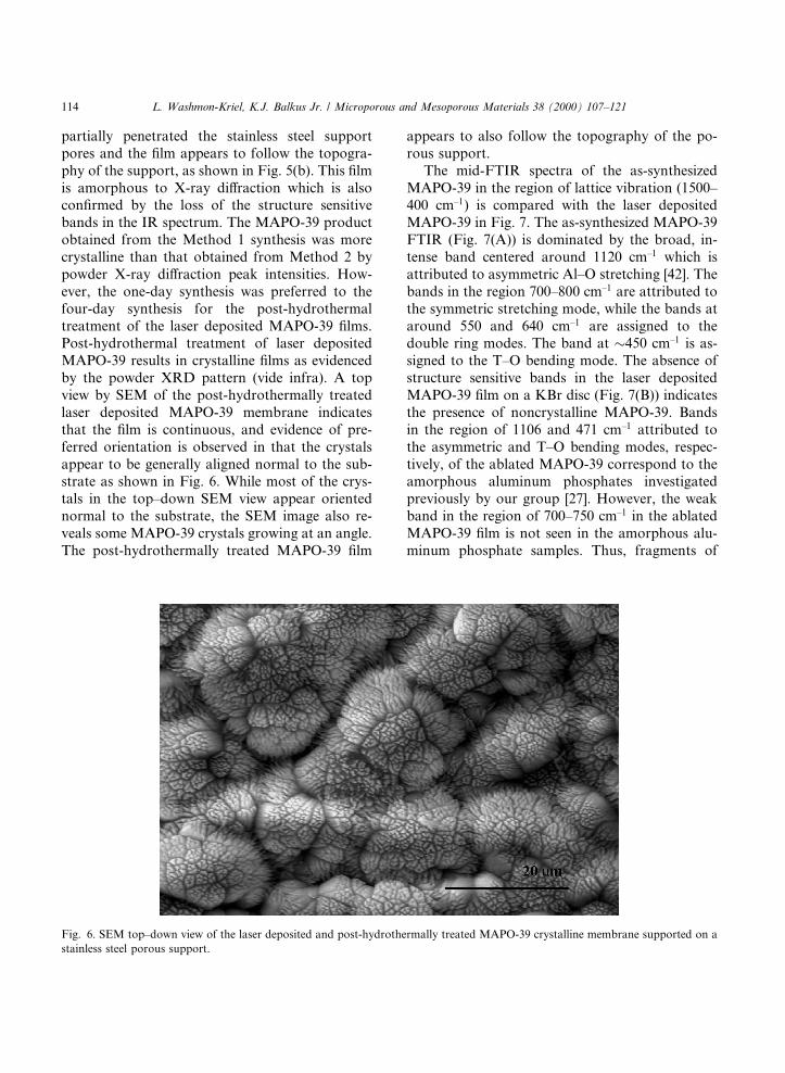
partially penetrated the stainless steel supportpores and the ®lm appears to follow the topogra-phy of the support, as shown in Fig. 5(b). This ®lmis amorphous to X-ray di�raction which is alsocon®rmed by the loss of the structure sensitivebands in the IR spectrum. The MAPO-39 productobtained from the Method 1 synthesis was morecrystalline than that obtained from Method 2 bypowder X-ray di�raction peak intensities. How-ever, the one-day synthesis was preferred to thefour-day synthesis for the post-hydrothermaltreatment of the laser deposited MAPO-39 ®lms.Post-hydrothermal treatment of laser depositedMAPO-39 results in crystalline ®lms as evidencedby the powder XRD pattern (vide infra). A topview by SEM of the post-hydrothermally treatedlaser deposited MAPO-39 membrane indicatesthat the ®lm is continuous, and evidence of pre-ferred orientation is observed in that the crystalsappear to be generally aligned normal to the sub-strate as shown in Fig. 6. While most of the crys-tals in the top±down SEM view appear orientednormal to the substrate, the SEM image also re-veals some MAPO-39 crystals growing at an angle.The post-hydrothermally treated MAPO-39 ®lm
appears to also follow the topography of the po-rous support.
The mid-FTIR spectra of the as-synthesizedMAPO-39 in the region of lattice vibration (1500±400 cm±1) is compared with the laser depositedMAPO-39 in Fig. 7. The as-synthesized MAPO-39FTIR (Fig. 7(A)) is dominated by the broad, in-tense band centered around 1120 cm±1 which isattributed to asymmetric Al±O stretching [42]. Thebands in the region 700±800 cm±1 are attributed tothe symmetric stretching mode, while the bands ataround 550 and 640 cm±1 are assigned to thedouble ring modes. The band at �450 cm±1 is as-signed to the T±O bending mode. The absence ofstructure sensitive bands in the laser depositedMAPO-39 ®lm on a KBr disc (Fig. 7(B)) indicatesthe presence of noncrystalline MAPO-39. Bandsin the region of 1106 and 471 cm±1 attributed tothe asymmetric and T±O bending modes, respec-tively, of the ablated MAPO-39 correspond to theamorphous aluminum phosphates investigatedpreviously by our group [27]. However, the weakband in the region of 700±750 cm±1 in the ablatedMAPO-39 ®lm is not seen in the amorphous alu-minum phosphate samples. Thus, fragments of
Fig. 6. SEM top±down view of the laser deposited and post-hydrothermally treated MAPO-39 crystalline membrane supported on a
stainless steel porous support.
114 L. Washmon-Kriel, K.J. Balkus Jr. / Microporous and Mesoporous Materials 38 (2000) 107±121
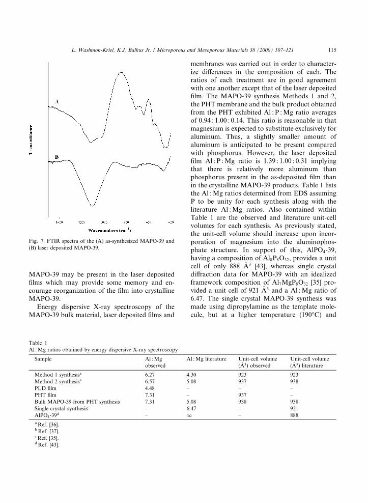
MAPO-39 may be present in the laser deposited®lms which may provide some memory and en-courage reorganization of the ®lm into crystallineMAPO-39.
Energy dispersive X-ray spectroscopy of theMAPO-39 bulk material, laser deposited ®lms and
membranes was carried out in order to character-ize di�erences in the composition of each. Theratios of each treatment are in good agreementwith one another except that of the laser deposited®lm. The MAPO-39 synthesis Methods 1 and 2,the PHT membrane and the bulk product obtainedfrom the PHT exhibited Al : P : Mg ratio averagesof 0.94 : 1.00 : 0.14. This ratio is reasonable in thatmagnesium is expected to substitute exclusively foraluminum. Thus, a slightly smaller amount ofaluminum is anticipated to be present comparedwith phosphorus. However, the laser deposited®lm Al : P : Mg ratio is 1.39 : 1.00 : 0.31 implyingthat there is relatively more aluminum thanphosphorus present in the as-deposited ®lm thanin the crystalline MAPO-39 products. Table 1 liststhe Al : Mg ratios determined from EDS assumingP to be unity for each synthesis along with theliterature Al : Mg ratios. Also contained withinTable 1 are the observed and literature unit-cellvolumes for each synthesis. As previously stated,the unit-cell volume should increase upon incor-poration of magnesium into the aluminophos-phate structure. In support of this, AlPO4-39,having a composition of Al8P8O32, provides a unitcell of only 888 �A3 [43], whereas single crystaldi�raction data for MAPO-39 with an idealizedframework composition of Al7MgP8O32 [35] pro-vided a unit cell of 921 �A3 and a Al : Mg ratio of6.47. The single crystal MAPO-39 synthesis wasmade using dipropylamine as the template mole-cule, but at a higher temperature (190°C) and
Table 1
Al : Mg ratios obtained by energy dispersive X-ray spectroscopy
Sample Al : Mg
observed
Al : Mg literature Unit-cell volume
(�A3) observed
Unit-cell volume
(�A3) literature
Method 1 synthesisa 6.27 4.30 923 923
Method 2 synthesisb 6.57 5.08 937 938
PLD ®lm 4.48 ± ± ±
PHT ®lm 7.31 ± 937 ±
Bulk MAPO-39 from PHT synthesis 7.31 5.08 938 938
Single crystal synthesisc ± 6.47 ± 921
AlPO4-39d ± 1 ± 888
a Ref. [36].b Ref. [37].c Ref. [35].d Ref. [43].
Fig. 7. FTIR spectra of the (A) as-synthesized MAPO-39 and
(B) laser deposited MAPO-39.
L. Washmon-Kriel, K.J. Balkus Jr. / Microporous and Mesoporous Materials 38 (2000) 107±121 115
di�erent synthesis time (48±60 h) compared withMethods 1 and 2. The Al : Mg ratio reported forMAPO-39 made by Methods 1 and 2 are signi®-cantly lower (4.30 and 5.08) compared to the singlecrystal sample. The Methods 1 and 2 synthesesprovided Al : Mg ratios of 6.27 and 6.57 whichmore closely approximate that reported from sin-gle crystal data. The observed Al : Mg ratios donot correlate directly to the unit-cell volume foreach synthesis method, however the observed unit-cell values compare very well with the reportedmaterials. This implies that there may be someextra framework Mg in the Method 1 and 2 syn-theses as well as in the literature syntheses. Thelaser deposited ®lm is signi®cantly enriched in bothaluminum and magnesium compared with phos-phorus based on the EDS results. Additionally, thePLD ®lm showed the highest Al : Mg ratio of allthe samples. However, the PHT crystallineMAPO-39 ®lm provided an Al : Mg ratio of 7.31,the same ratio seen in the bulk MAPO-39 obtainedfrom PHT syntheses. This result may imply thatthe magnesium enrichment of the thin PLD ®lm(<200 nm) does not dramatically in¯uence thecomposition of the ®nal 45 lm ®lm (24 h synthe-sis). In any case, the PHT ®lm exhibits a unit cell
(937 �A3) and Al : Mg ratio consistent with MAPO-39 as prepared by Method 2.
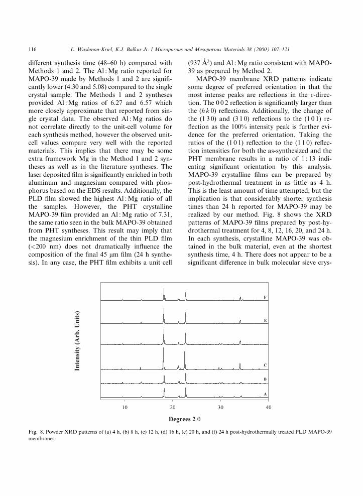
MAPO-39 membrane XRD patterns indicatesome degree of preferred orientation in that themost intense peaks are re¯ections in the c-direc-tion. The 0 0 2 re¯ection is signi®cantly larger thanthe (h k 0) re¯ections. Additionally, the change ofthe (1 3 0) and (3 1 0) re¯ections to the (1 0 1) re-¯ection as the 100% intensity peak is further evi-dence for the preferred orientation. Taking theratios of the (1 0 1) re¯ection to the (1 1 0) re¯ec-tion intensities for both the as-synthesized and thePHT membrane results in a ratio of 1 : 13 indi-cating signi®cant orientation by this analysis.MAPO-39 crystalline ®lms can be prepared bypost-hydrothermal treatment in as little as 4 h.This is the least amount of time attempted, but theimplication is that considerably shorter synthesistimes than 24 h reported for MAPO-39 may berealized by our method. Fig. 8 shows the XRDpatterns of MAPO-39 ®lms prepared by post-hy-drothermal treatment for 4, 8, 12, 16, 20, and 24 h.In each synthesis, crystalline MAPO-39 was ob-tained in the bulk material, even at the shortestsynthesis time, 4 h. There does not appear to be asigni®cant di�erence in bulk molecular sieve crys-
Fig. 8. Powder XRD patterns of (a) 4 h, (b) 8 h, (c) 12 h, (d) 16 h, (e) 20 h, and (f) 24 h post-hydrothermally treated PLD MAPO-39
membranes.
116 L. Washmon-Kriel, K.J. Balkus Jr. / Microporous and Mesoporous Materials 38 (2000) 107±121
tallinity when comparing the XRD intensities ofthe shorter synthesis times to the longer synthesistimes of the literature procedure [37]. However, asthe synthesis time increases, small impurity peaksat �18.4° and �34.5° two theta are observed. It ispossible that these peaks arise from the formationof an impurity of MAPO-34; however, this has notbeen veri®ed.
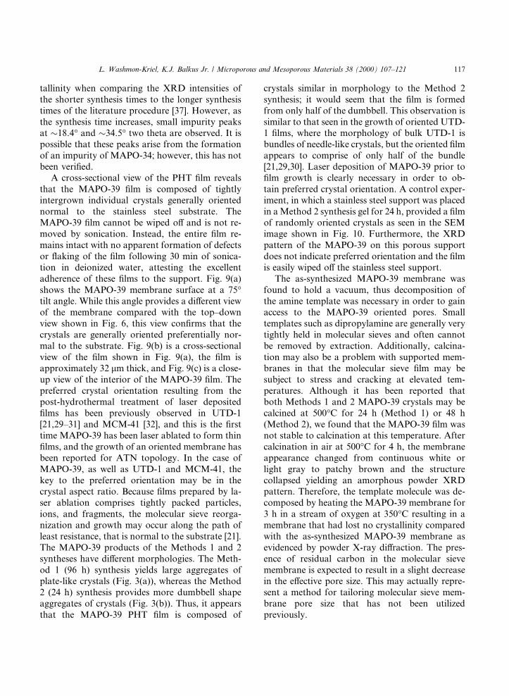
A cross-sectional view of the PHT ®lm revealsthat the MAPO-39 ®lm is composed of tightlyintergrown individual crystals generally orientednormal to the stainless steel substrate. TheMAPO-39 ®lm cannot be wiped o� and is not re-moved by sonication. Instead, the entire ®lm re-mains intact with no apparent formation of defectsor ¯aking of the ®lm following 30 min of sonica-tion in deionized water, attesting the excellentadherence of these ®lms to the support. Fig. 9(a)shows the MAPO-39 membrane surface at a 75°tilt angle. While this angle provides a di�erent viewof the membrane compared with the top±downview shown in Fig. 6, this view con®rms that thecrystals are generally oriented preferentially nor-mal to the substrate. Fig. 9(b) is a cross-sectionalview of the ®lm shown in Fig. 9(a), the ®lm isapproximately 32 lm thick, and Fig. 9(c) is a close-up view of the interior of the MAPO-39 ®lm. Thepreferred crystal orientation resulting from thepost-hydrothermal treatment of laser deposited®lms has been previously observed in UTD-1[21,29±31] and MCM-41 [32], and this is the ®rsttime MAPO-39 has been laser ablated to form thin®lms, and the growth of an oriented membrane hasbeen reported for ATN topology. In the case ofMAPO-39, as well as UTD-1 and MCM-41, thekey to the preferred orientation may be in thecrystal aspect ratio. Because ®lms prepared by la-ser ablation comprises tightly packed particles,ions, and fragments, the molecular sieve reorga-nization and growth may occur along the path ofleast resistance, that is normal to the substrate [21].The MAPO-39 products of the Methods 1 and 2syntheses have di�erent morphologies. The Meth-od 1 (96 h) synthesis yields large aggregates ofplate-like crystals (Fig. 3(a)), whereas the Method2 (24 h) synthesis provides more dumbbell shapeaggregates of crystals (Fig. 3(b)). Thus, it appearsthat the MAPO-39 PHT ®lm is composed of
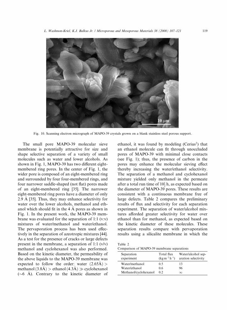
crystals similar in morphology to the Method 2synthesis; it would seem that the ®lm is formedfrom only half of the dumbbell. This observation issimilar to that seen in the growth of oriented UTD-1 ®lms, where the morphology of bulk UTD-1 isbundles of needle-like crystals, but the oriented ®lmappears to comprise of only half of the bundle[21,29,30]. Laser deposition of MAPO-39 prior to®lm growth is clearly necessary in order to ob-tain preferred crystal orientation. A control exper-iment, in which a stainless steel support was placedin a Method 2 synthesis gel for 24 h, provided a ®lmof randomly oriented crystals as seen in the SEMimage shown in Fig. 10. Furthermore, the XRDpattern of the MAPO-39 on this porous supportdoes not indicate preferred orientation and the ®lmis easily wiped o� the stainless steel support.
The as-synthesized MAPO-39 membrane wasfound to hold a vacuum, thus decomposition ofthe amine template was necessary in order to gainaccess to the MAPO-39 oriented pores. Smalltemplates such as dipropylamine are generally verytightly held in molecular sieves and often cannotbe removed by extraction. Additionally, calcina-tion may also be a problem with supported mem-branes in that the molecular sieve ®lm may besubject to stress and cracking at elevated tem-peratures. Although it has been reported thatboth Methods 1 and 2 MAPO-39 crystals may becalcined at 500°C for 24 h (Method 1) or 48 h(Method 2), we found that the MAPO-39 ®lm wasnot stable to calcination at this temperature. Aftercalcination in air at 500°C for 4 h, the membraneappearance changed from continuous white orlight gray to patchy brown and the structurecollapsed yielding an amorphous powder XRDpattern. Therefore, the template molecule was de-composed by heating the MAPO-39 membrane for3 h in a stream of oxygen at 350°C resulting in amembrane that had lost no crystallinity comparedwith the as-synthesized MAPO-39 membrane asevidenced by powder X-ray di�raction. The pres-ence of residual carbon in the molecular sievemembrane is expected to result in a slight decreasein the e�ective pore size. This may actually repre-sent a method for tailoring molecular sieve mem-brane pore size that has not been utilizedpreviously.
L. Washmon-Kriel, K.J. Balkus Jr. / Microporous and Mesoporous Materials 38 (2000) 107±121 117
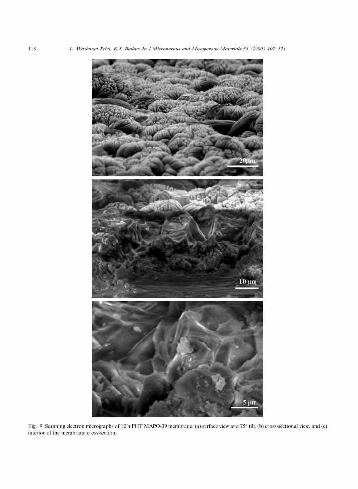
Fig. 9. Scanning electron micrographs of 12 h PHT MAPO-39 membrane: (a) surface view at a 75° tilt, (b) cross-sectional view, and (c)
interior of the membrane cross-section.
118 L. Washmon-Kriel, K.J. Balkus Jr. / Microporous and Mesoporous Materials 38 (2000) 107±121
The small pore MAPO-39 molecular sievemembrane is potentially attractive for size andshape selective separation of a variety of smallmolecules such as water and lower alcohols. Asshown in Fig. 1, MAPO-39 has two di�erent eight-membered ring pores. In the center of Fig. 1, thewider pore is composed of an eight-membered ringand surrounded by four four-membered rings, andfour narrower saddle-shaped (not ¯at) pores madeof an eight-membered ring [35]. The narrowereight-membered ring pores have a diameter of only2.9 �A [35]. Thus, they may enhance selectivity forwater over the lower alcohols, methanol and eth-anol which should ®t in the 4 �A pores as shown inFig. 1. In the present work, the MAPO-39 mem-brane was evaluated for the separation of 1:1 (v:v)mixtures of water/methanol and water/ethanol.The pervaporation process has been used e�ec-tively in the separation of azeotropic mixtures [44].As a test for the presence of cracks or large defectspresent in the membrane, a separation of 1:1 (v/v)methanol and cyclohexanol was also performed.Based on the kinetic diameter, the permeability ofthe above liquids to the MAPO-39 membrane wasexpected to follow the order: water �2:65�A� >methanol �3:8�A� > ethanol �4:3�A� � cyclohexanol(�6 �A). Contrary to the kinetic diameter of
ethanol, it was found by modeling (Cerius2) thatan ethanol molecule can ®t through unoccludedpores of MAPO-39 with minimal close contacts(see Fig. 1); thus, the presence of carbon in thepores may enhance the molecular sieving e�ectthereby increasing the water/ethanol selectivity.The separation of a methanol and cyclohexanolmixture yielded only methanol in the permeateafter a total run time of 101
2h, as expected based on
the diameter of MAPO-39 pores. These results areconsistent with a continuous membrane free oflarge defects. Table 2 compares the preliminaryresults of ¯ux and selectivity for each separationexperiment. The separation of water/alcohol mix-tures a�orded greater selectivity for water overethanol than for methanol, as expected based onthe kinetic diameter of these molecules. Theseseparation results compare with pervaporationresults using a silicalite membrane in which the
Fig. 10. Scanning electron micrograph of MAPO-39 crystals grown on a blank stainless steel porous support.
Table 2
Comparison of MAPO-39 membrane separations
Separation
experiment
Total ¯ux
(kg m±2 h±1)
Water/alcohol sep-
aration selectivity
Water/methanol 0.5 13
Water/ethanol 0.6 96
Methanol/cyclohexanol 0.2 1
L. Washmon-Kriel, K.J. Balkus Jr. / Microporous and Mesoporous Materials 38 (2000) 107±121 119
best performance was obtained in the separa-tion of a 5 vol% ethanol solution providinga EtOH=H2O � 120 [45]. In a similar experiment,the separation of methanol and water yielded aseparation factor a of value 23. A pervaporationexperiment providing separation factors of �5000for water over ethanol at temperatures rangingfrom 50±120°C have been reported from a 5 wt.%water feed using a NaA zeolite membrane grownon aluminosilicate supports [9]. The NaA mem-brane was found to be a composite of three layers,the outer layer being the zeolite ®lm, the innerlayer the support, and the layer between was foundto have an intermediate composition. NaA andMAPO-39 each have 4 �A diameter pores; thus, thedi�erence in selectivity for water/alcohol separa-tion between the two membranes may re¯ect thedi�erence in support and conditions for the sepa-rations. Also, one cannot rule out small defectsthat were not made evident by the cyclohexanolpervaporation experiment. Nevertheless, theMAPO-39 ®lms hold promise for the separation ofsmall molecules.
4. Conclusions
MAPO-39 molecular sieves have been laserablated for the ®rst time. Post-hydrothermaltreatment of the PLD MAPO-39 ®lm produces amostly oriented membrane. The mechanism oforiented MAPO-39 ®lm growth is the subject ofcontinuing investigation, but there is some simi-larity with UTD-1 in that both materials formaggregates of small plank- or needle-shaped crys-tals. This appears to be the ®rst report on an ori-ented ®lm having ATN topology and the ®rstreport on a MgAlPO4 molecular sieve ®lm. It isanticipated that other structures and compositionswill yield similar ®lms and membranes using thePLD technique.
Acknowledgements
The authors thank the National Science Foun-dation, the Robert A. Welch Foundation and theACS-PRF for ®nancial support of this work.
References
[1] D.C. Breck, Zeolite Molecular Sieves, Wiley, New York,
1974.
[2] T. Bein, Chem. Mater. 8 (1996) 1636.
[3] L.C. Boudreau, M. Tsapatsis, Chem. Mater. 9 (1997) 1705.
[4] M.C. Lovallo, M. Tsapatsis, Chem. Mater. 8 (1996) 1579.
[5] M.C. Lovallo, M. Tsapatsis, AIChE J. 42 (1996) 3020.
[6] M.C. Lovallo, A. Gouzinis, M. Tsapatsis, AIChE J. 44
(1998) 1903.
[7] G. Xomeritakis, M. Tsapatsis, Chem. Mater. 11 (1999)
875.
[8] A. Gouzinis, M. Tsapatsis, Chem. Mater. 10 (1998) 2497.
[9] M. Kondo, M. Komori, H. Kita, K.-I. Okamoto, J. Mem.
Sci. 133 (1998) 133.
[10] H. Kita, T. Inoue, H. Asamura, K. Tanaka, K. Okamoto,
J. Chem. Soc., Chem. Commun. (1997) 45.
[11] S. Mintova, V. Valtchev, V. Engstr�om, B.J. Schoeman,
J. Sterte, Micropor. Mater. 11 (1997) 149.
[12] S. Mintova, J. Hedlund, V. Valtchev, B.J. Schoeman,
J. Sterte, J. Mater. Chem. 8 (1998) 2217.
[13] J. Sterte, S. Mintova, G. Zhang, B.J. Schoeman, Zeolites
18 (1997) 387.
[14] J.H. Koegler, A. Arafat, H. van Bekkum, J.C. Jansen,
Stud. Surf. Sci. Catal. 105 (1997) 2163.
[15] J.C. Jansen, W. Nugroho, H. van Bekkum, in: R. von
Ballmoos, J.B. Higgins, M.M.J. Treacy (Eds.), Proceedings
of the Ninth International Zeolite Conference, vol. 1,
Butterworth, London, 1993, p. 247.
[16] J.C. Jansen, D. Kashchiev, A. Erdem-Senatalar, Stud.
Surf. Sci. Catal. 85 (1994) 215.
[17] Y. Yan, M.E. Davis, G.R. Gavalas, Ind. Engng. Chem.
Res. 34 (1995) 1652.
[18] P. K�olsch, D. Venke, M. Noack, E. Lieske, P. Toussaint,
J. Caro, Stud. Surf. Sci. Catal. 84 (1994) 1075.
[19] T. Sano, Y. Kiyozumi, M. Kawamura, F. Mizukami,
H. Takaya, T. Mouri, W. Inaoka, Y. Toida, M. Watanabe,
K. Toyoda, Zeolites 11 (1991) 842.
[20] T.-G. Tsai, H.-C. Shih, S.-J. Liao, K.-J. Chao, Micropor.
Mesopor. Mater. 22 (1998) 333.
[21] T. Mu~noz, K.J. Balkus Jr., J. Am. Chem. Soc. 121 (1999)
139.
[22] K.J. Balkus Jr., T. Mu~noz, M.E. Gimon-Kinsel, Chem.
Mater. 10 (1998) 464.
[23] K.J. Balkus Jr., L. Sottile, S.J. Riley, B.E. Gnade, Thin
Solid Films 260 (1995) 4.
[24] L. Sottile, K.J. Balkus Jr., S.J. Riley, B.E. Gnade, Mater.
Res. Soc. Symp. Proc. 351 (1994) 264.
[25] K.J. Balkus Jr., L.J. Sottile, H. Nguyen, S.J. Riley, B.E.
Gnade, Mater. Res. Soc. Symp. Proc. 371 (1995) 33.
[26] K.J. Balkus Jr., L.J. Ball, B.E. Gnade, J.M. Anthony,
Chem. Mater. 9 (1997) 380.
[27] T. Mu~noz Jr., K.J. Balkus Jr., Chem. Mater. 10 (1998)
4114.
[28] M.E. Gimon-Kinsel, K.J. Balkus Jr., Micropor. Mesopor.
Mater. 28 (1999) 113.
[29] K.J. Balkus Jr., A.S. Scott, Chem. Mater. 11 (1999) 189.
120 L. Washmon-Kriel, K.J. Balkus Jr. / Microporous and Mesoporous Materials 38 (2000) 107±121
[30] K.J. Balkus Jr., A.S. Scott, Micropor. Mesopor. Mater. 34
(2000) 31.
[31] K.J. Balkus Jr., A.K. Khanmamedova, A. Scott, J.
Hoefelmeyer in: M.M.J. Treacy, B.K. Marcus, M.E.
Bisher, J.B. Higgins (Eds.), Proceedings of the 12th
International Zeolite Conference, vol. 2, Materials Re-
search Society, Warrendale, 1999, p. 1403.
[32] K.J. Balkus Jr., A.S. Scott, M.E. Gimon-Kinsel, J.H.
Blanco, Micropor. Mesopor. Mater. 38 (2000) 97.
[33] L.B. McCusker, G.O. Brunner, A.F. Ojo, W.H. Baur, in:
W.M. Meier, D.H. Olson (Eds.), Atlas of Zeolite Structure
Types, Third ed., Butterworth, USA, 1992, p. 50.
[34] E.M. Flanigen, B.M. Lok, R.L. Patton, S.T. Wilson, Pure
and Appl. Chem. 58 (1986) 1351.
[35] W.H. Baur, W. Joswig, D. Kassner, A. Bieniok, G. Finger,
J. Kornatowski, Z. Kristallogr. 214 (1999) 154.
[36] D.B. Akolekar, S.K. Kaliaguine, Zeolites 14 (1994) 620.
[37] S.T. Wilson, E.M. Flanigen, US Patent, 4,567,029, 1986.
[38] K.J. Balkus Jr., S.J. Riley, B.E. Gnade, Mater. Res. Soc.
Symp. Proc. 351 (1994) 437.
[39] S.T. Wilson, E.M. Flanigen in: M.L. Occelli, H.E. Robson
(Eds.), Zeolite Synthesis, ACS Symp. Ser., Ameri-
can Chemical Society, Washington, DC, 398 (1989)
329.
[40] L.B. McCusker, G.O. Brunner, A.F. Oju, Acta Crystallogr.
A 46 (1990) C59.
[41] D.B. Chrissey, G.K. Hubler, Pulsed Laser Deposition of
Thin Films, Wiley, New York, 1994.
[42] E.M. Flanigen, in: J.A. Rabo (Ed.), Zeolite Chemistry and
Catalysis, vol. 171, ACS Monograph, American Chemical
Society, Washington, DC, 1976, p. 80.
[43] L.B. McCusker, G.O. Brunner, A.F. Ojo, in: M.M.J.
Treacy, J.B. Higgins, R. von Ballmoos (Eds.), Col-
lection of Simulated XRD Powder Patterns for Zeo-
lites, Third revised ed., Elsevier, New York, 1996,
p. 380.
[44] H.L. Fleming, Chem. Engng. Prog., July 1992, p. 46.
[45] H. Yanagishita, D. Kitamoto, K. Haraya, T. Nakane, M.
Satoh, H. Matsuda, H. Suetoshi, N. Koura, T. Sano, in:
Proceedings of Euromembrane, 1997, p. 364.
L. Washmon-Kriel, K.J. Balkus Jr. / Microporous and Mesoporous Materials 38 (2000) 107±121 121


