PIPE
S A
ND
FIT
TIN
GS
IN P
P-R

Edition 3: 07/18
3
i
InDeX
1. GeneRAl InFORmATIOn pag. 4
2. COPRAX SYSTem PROPeRTIeS pag. 6
3. COPRAX FIBRA SYSTem PROPeRTIeS pag. 8
4. TeCHnICAl InFORmATIOnS pag. 9
5. GuARAnTee pag. 20
6. InSTRuCTIOnS FOR uSe pag. 22
7. CHemICAl ReSISTAnCe pag. 31
8. PReSSuRe lOSS pag. 37
9. THeRmAl InSulATIOn pag. 43
10.TeCHnICAl InSTAllATIOn pag. 44
11. PReCAuTIOnS pag. 53
12.TeSTInG pag. 56
13. FITTInGS DImenSIOn pag. 57
1. GENERAL INFORMATION
4
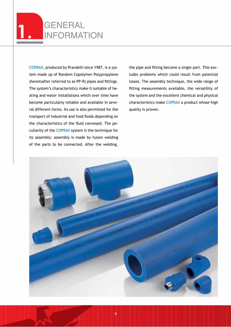
COPRAX, produced by Prandelli since 1987, is a sys-
tem made up of Random Copolymer Polypropylene
(hereinafter referred to as PP-R) pipes and fittings.
The system’s characteristics make it suitable of he-
ating and water installations which over time have
become particularly reliable and available in seve-
ral different forms. Its use is also permitted for the
transport of industrial and food fluids depending on
the characteristics of the fluid conveyed. The pe-
culiarity of the COPRAX system is the technique for
its assembly: assembly is made by fusion welding
of the parts to be connected. After the welding,
the pipe and fitting become a single part. This exc-
ludes problems which could result from potential
losses. The assembly technique, the wide range of
fitting measurements available, the versatility of
the system and the excellent chemical and physical
characteristics make COPRAX a product whose high
quality is proven.
The COPRAX system is made from a Random Copo-
lymer Polypropylene (PP-R) approved for the pro-
duction of pipes according to the standards DIN
8078 (Polypropylene Pipes. General Quality Requi-
rements - Tests) and UNI EN ISO 15874.
Before processing, the granule is submitted to spe-
cific tests in our laboratories to verify its suitability
for use (ISO/R 1133 procedure 18. Melt index MFI
190/5).
PP-R is a thermoplastic resin which is transformed
into the finished product by a rise in temperature,
which plasticizes the material, allowing the pipe to
be produced by means of extrusion, and the fittings
by moulding.
These processes are carried out inside our factory,
under the control of skilled, qualified staff. The
dimensions of the pipes and fittings, with the rela-
tive processing tolerances, are established in accor-
dance with the standard UNI EN ISO 15874 (Pipes in
polypropylene, PP, dimensions) Pipes are produced
in the following Series: S5, S3.2 and S2.5.
5
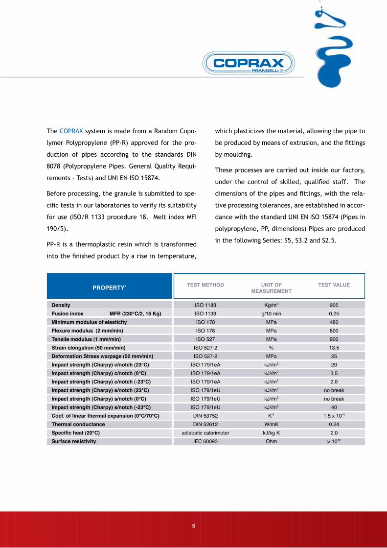
DensityFusion index MFR (230°C/2, 16 Kg)Minimum modulus of elasticityFlexure modulus (2 mm/min)Tensile modulus (1 mm/min)Strain elongation (50 mm/min)Deformation Stress warpage (50 mm/min)Impact strength (Charpy) c/notch (23°C)Impact strength (Charpy) c/notch (0°C)Impact strength (Charpy) c/notch (-23°C)Impact strength (Charpy) s/notch (23°C)Impact strength (Charpy) s/notch (0°C)Impact strength (Charpy) s/notch (-23°C)Coef. of linear thermal expansion (0°C/70°C)Thermal conductanceSpecific heat (20°C)Surface resistivity
PROPERTY’
ISO 1183ISO 1133ISO 178ISO 178ISO 527
ISO 527-2ISO 527-2
ISO 179/1eAISO 179/1eAISO 179/1eAISO 179/1eUISO 179/1eUISO 179/1eUDIN 53752DIN 52612
adiabatic calorimeterIEC 60093
Kg/m3
g/10 minMPaMPaMPa
%MPa
kJ//m2
kJ//m2
kJ//m2
kJ//m2
kJ//m2
kJ//m2
K-1
W/mKkJ/kg K
Ohm
9050.2548080090013.525203.52.0
no breakno break
401.5 x 10⁻⁴
0.242.0
> 1012
TEST METHOD UNIT OF MEASUREMENT
TEST VALUE
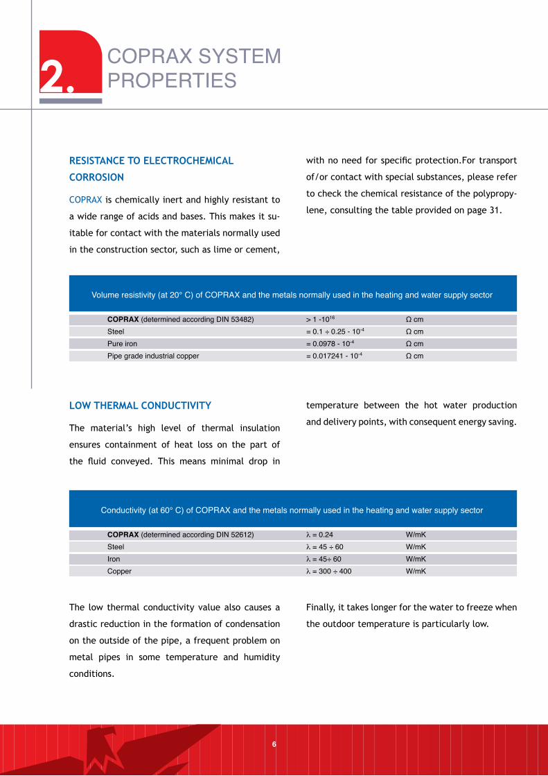
ReSISTAnCe TO eleCTROCHemICAl
CORROSIOn
COPRAX is chemically inert and highly resistant to
a wide range of acids and bases. This makes it su-
itable for contact with the materials normally used
in the construction sector, such as lime or cement,
with no need for specific protection.For transport
of/or contact with special substances, please refer
to check the chemical resistance of the polypropy-
lene, consulting the table provided on page 31.
6
lOW THeRmAl COnDuCTIVITY
The material’s high level of thermal insulation
ensures containment of heat loss on the part of
the fluid conveyed. This means minimal drop in
temperature between the hot water production
and delivery points, with consequent energy saving.
COPRAX (determined according DIN 53482) > 1 -1016 Ω cm Steel = 0.1 ÷ 0.25 - 10-4 Ω cm Pure iron = 0.0978 - 10-4 Ω cm Pipe grade industrial copper = 0.017241 - 10-4 Ω cm
Volume resistivity (at 20° C) of COPRAX and the metals normally used in the heating and water supply sector
COPRAX (determined according DIN 52612) λ = 0.24 W/mK Steel λ = 45 ÷ 60 W/mK Iron λ = 45÷ 60 W/mK Copper λ = 300 ÷ 400 W/mK
Conductivity (at 60° C) of COPRAX and the metals normally used in the heating and water supply sector
The low thermal conductivity value also causes a
drastic reduction in the formation of condensation
on the outside of the pipe, a frequent problem on
metal pipes in some temperature and humidity
conditions.
Finally, it takes longer for the water to freeze when
the outdoor temperature is particularly low.
COPRAX SYSTEM PROPERTIES2.
lOW nOISe
Due to the material’s high sound insulation value, the
noise level of the systems is considerably reduced
both with particularly high water flow speeds and
when water hammers are present.
HYGIenIC AnD nOn-TOXIC
PP-R, the raw material used for production of
the COPRAX system, is completely non-toxic and
complies with the current standards at international
level.
ReSISTAnCe TO STRAY eleCTRIC CuRRenTS
Due to its high electrical insulating properties,
COPRAX is unaffected by stray currents, which
may create dangerous punctures in metal pipes.
This phenomenon occurs above all in installations
in zones with a high concentration of industrial
facilities, close to railway lines and in other zones
with a high concentration of electrostatic currents.
lOW lOSS OF PReSSuRe
Due to the particularly homogeneous, compact
structure of the material, achieved by using a state
of the art production technology, the inside surface
of COPRAX pipes and fittings is non- porous and free
from cracks or crazing. This means the surface is
extremely smooth, and loss of pressure is very low
(see graphs on page 38/39).
There is also no risk of pipe blockages caused by
scale deposits.
eASY WORKABIlITY
Due to the density of just 0.905 g/cm3, the pipes
and fittings are very light. Combined with the wide
range of fittings available, this enables installations
to be made easily and safely, with considerable time
saving compared to conventional products.
7
3. COPRAX FIBRASYSTEM PROPERTIES
COPRAX FIBRA
is produced through coextrusion of two distinct ma-
terial, and the result is the pipe wall is made from 3
different layers as follows:
1. Inner layer, in direct contact with water,
made from PPR
2. Intermediate layer, made from PPR and Fi
ber Glass (GF)
3. Outer layer, made from PPR
The production process allows us to realize all the
three layers in a unique production phase. The th-
ree layers are linked together through the common
PPR raw material.
The main advantage related to the presence of fiber
glass raw material is the impressive reduction of the
linear expansion coefficient of the finished product.
This advantage allows the plumber to reduce the
number of clamps in case of external installation.
We recommend in any case to follow the installation
guideline chapter in the technical guide.
The regular COPRAX fittings are suitable for connec-
tion with COPRAX FIBRA pipe, and the installation
technique is the same used for the normal COPRAX
pipe, because the welding point is only the outer
layer of the COPRAX FIBRA pipe.
ADVAnTAGeS
• Linear expansion reduced up to 60%
• Higher stability
• Versatility in the external installation works
SOme OF THe FIelDS OF APPlICATIOn
• Hot and cold, potable water installation
• High rise installation
• Industrial installation
• Compressed air transportation
• Air conditioning systems
8
9
Checking the resistence of a product is achieved by
taking the following into consideration:
1. The mATeRIAl that it is made of.
2. The DemAnDS placed upon it.
1. COPRAX system is produced with PP-R. Its
behaviour characteristics when faced with stress
are summarised in the so-called „regression
curves”. These represent the material’s identity
card and provides the answer to environmental
stress.
2. The stresses to which a thermohydraulic system
is exposed are numerous. To keep it simple let us
imagine that the fluid transported is water and
the environment in which the system operates is
not equipped with specific features. Otherwise
these eventual particular features would impact
negatively on product durability.
Having made this preliminary observation, we can
state that the stresses that define the system’s
working conditions, for transporting hot and cold
water, are:
- TemPeRATuRe
- TIme
- PReSSuRe
Starting from the regression curves of the material
that makes up the base matter from which the
COPRAX range tubes and fittings are designed, once
the work temperature and the working time have
been set, following table of maximum pressures for
continued use can be compiled. The table shown has
been calculated by considering a safety coefficient
equal to C = 1.5 for all conditions. This is the
predicted value for the design temperature.
4. TECHNICALINFORMATIONS
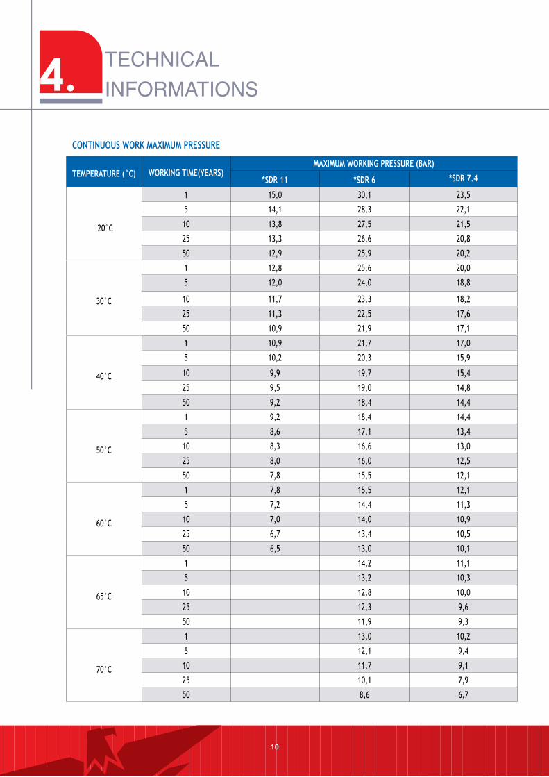
TemPeRATuRe (°C) WORKInG TIme(YeARS)mAXImum WORKInG PReSSuRe (BAR)
*SDR 11 *SDR 6 *SDR 7.4
20°C
1 15,0 30,1 23,5
5 14,1 28,3 22,1
10 13,8 27,5 21,5
25 13,3 26,6 20,8
50 12,9 25,9 20,2
30°C
1 12,8 25,6 20,0
5 12,0 24,0 18,8
10 11,7 23,3 18,2
25 11,3 22,5 17,6
50 10,9 21,9 17,1
40°C
1 10,9 21,7 17,0
5 10,2 20,3 15,9
10 9,9 19,7 15,4
25 9,5 19,0 14,8
50 9,2 18,4 14,4
50°C
1 9,2 18,4 14,4
5 8,6 17,1 13,4
10 8,3 16,6 13,0
25 8,0 16,0 12,5
50 7,8 15,5 12,1
60°C
1 7,8 15,5 12,1
5 7,2 14,4 11,3
10 7,0 14,0 10,9
25 6,7 13,4 10,5
50 6,5 13,0 10,1
65°C
1 14,2 11,1
5 13,2 10,3
10 12,8 10,0
25 12,3 9,6
50 11,9 9,3
70°C
1 13,0 10,2
5 12,1 9,4
10 11,7 9,1
25 10,1 7,9
50 8,6 6,7
TECHNICAL INFORMATIONS
COnTInuOuS WORK mAXImum PReSSuRe
10
4.
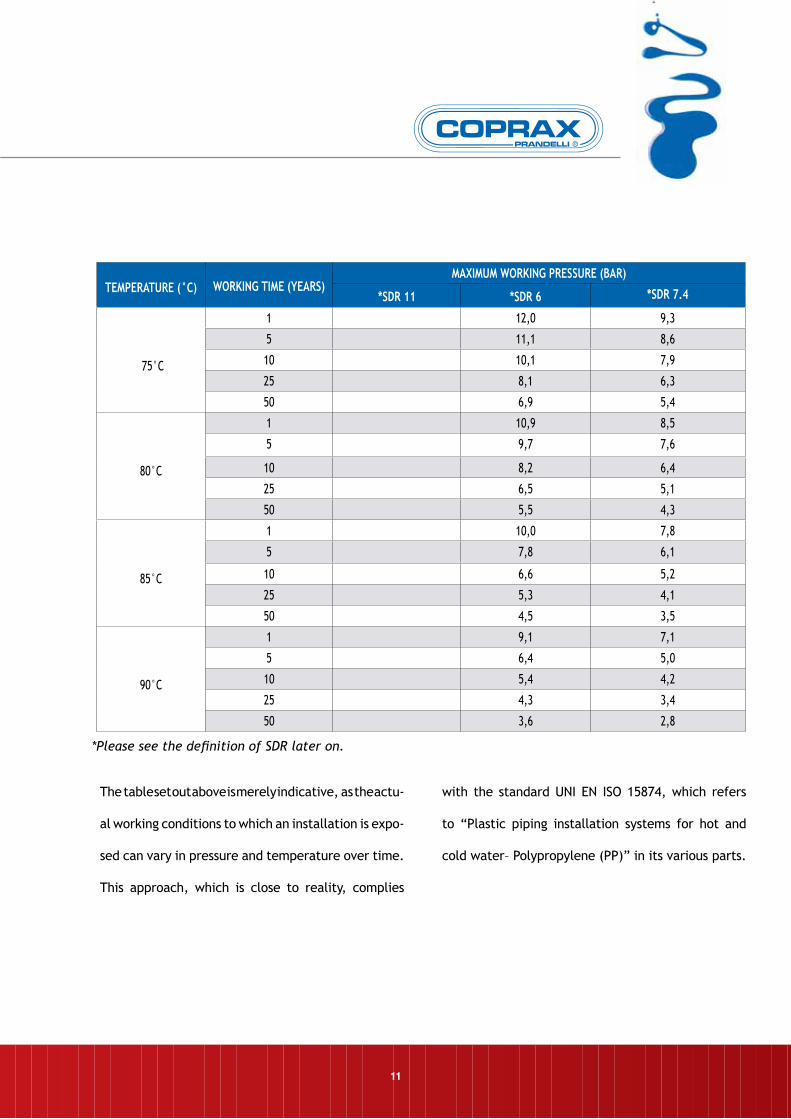
TemPeRATuRe (°C) WORKInG TIme (YeARS)mAXImum WORKInG PReSSuRe (BAR)
*SDR 11 *SDR 6 *SDR 7.4
75°C
1 12,0 9,3
5 11,1 8,6
10 10,1 7,9
25 8,1 6,3
50 6,9 5,4
80°C
1 10,9 8,5
5 9,7 7,6
10 8,2 6,4
25 6,5 5,1
50 5,5 4,3
85°C
1 10,0 7,8
5 7,8 6,1
10 6,6 5,2
25 5,3 4,1
50 4,5 3,5
90°C
1 9,1 7,1
5 6,4 5,0
10 5,4 4,2
25 4,3 3,4
50 3,6 2,8
*Please see the definition of SDR later on.
The table set out above is merely indicative, as the actu-
al working conditions to which an installation is expo-
sed can vary in pressure and temperature over time.
This approach, which is close to reality, complies
with the standard UNI EN ISO 15874, which refers
to “Plastic piping installation systems for hot and
cold water– Polypropylene (PP)” in its various parts.
11
4. TECHNICAL INFORMATIONS
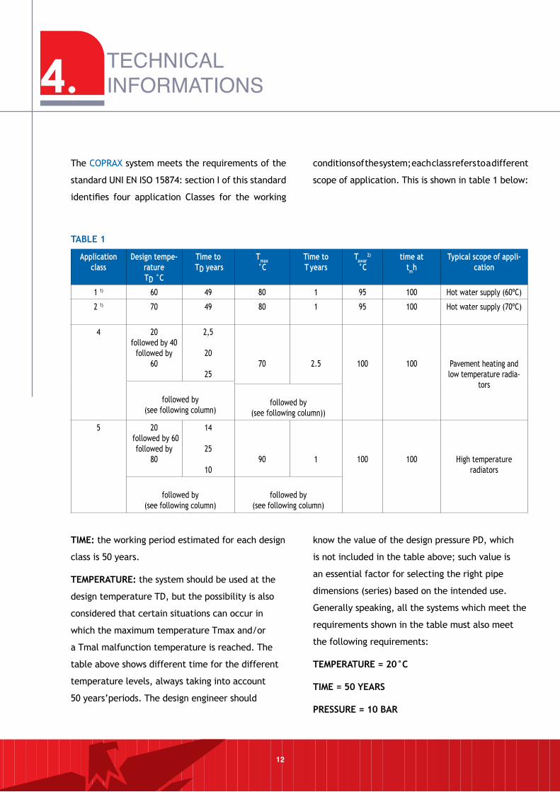
12
Application class
Design tempe-ratureTD °C
Time to TD years
Tmax°C
Time toT years
Tawar2)
°Ctime at
tmhTypical scope of appli-
cation
1 1) 60 49 80 1 95 100 Hot water supply (60ºC)
2 1) 70 49 80 1 95 100 Hot water supply (70ºC)
4 20followed by 40
followed by60
2,5
20
2570 2.5 100 100 Pavement heating and
low temperature radia-tors
followed by(see following column)
followed by(see following column))
5 20followed by 60followed by
80
14
25
1090 1 100 100 High temperature
radiators
followed by(see following column)
followed by(see following column)
The COPRAX system meets the requirements of the
standard UNI EN ISO 15874: section I of this standard
identifies four application Classes for the working
conditions of the system; each class refers to a different
scope of application. This is shown in table 1 below:
TABle 1
TIme: the working period estimated for each design
class is 50 years.
TemPeRATuRe: the system should be used at the
design temperature TD, but the possibility is also
considered that certain situations can occur in
which the maximum temperature Tmax and/or
a Tmal malfunction temperature is reached. The
table above shows different time for the different
temperature levels, always taking into account
50 years’periods. The design engineer should
know the value of the design pressure PD, which
is not included in the table above; such value is
an essential factor for selecting the right pipe
dimensions (series) based on the intended use.
Generally speaking, all the systems which meet the
requirements shown in the table must also meet
the following requirements:
TemPeRATuRe = 20°C
TIme = 50 YeARS
PReSSuRe = 10 BAR
13
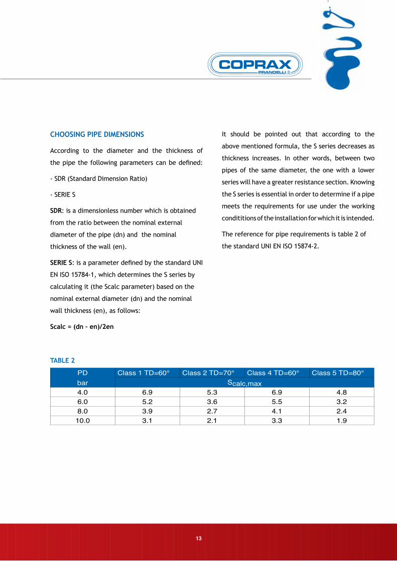
TABle 2
CHOOSInG PIPe DImenSIOnS
According to the diameter and the thickness of
the pipe the following parameters can be defined:
- SDR (Standard Dimension Ratio)
- SERIE S
SDR: is a dimensionless number which is obtained
from the ratio between the nominal external
diameter of the pipe (dn) and the nominal
thickness of the wall (en).
SeRIe S: is a parameter defined by the standard UNI
EN ISO 15784-1, which determines the S series by
calculating it (the Scalc parameter) based on the
nominal external diameter (dn) and the nominal
wall thickness (en), as follows:
Scalc = (dn – en)/2en
It should be pointed out that according to the
above mentioned formula, the S series decreases as
thickness increases. In other words, between two
pipes of the same diameter, the one with a lower
series will have a greater resistance section. Knowing
the S series is essential in order to determine if a pipe
meets the requirements for use under the working
condititions of the installation for which it is intended.
The reference for pipe requirements is table 2 of
the standard UNI EN ISO 15874-2.
PDbar
Class 1 TD=60° Class 2 TD=70° Class 4 TD=60° Class 5 TD=80°Scalc,max
4.0 6.9 5.3 6.9 4.86.0 5.2 3.6 5.5 3.28.0 3.9 2.7 4.1 2.410.0 3.1 2.1 3.3 1.9
4. TECHNICALINFORMATIONS
14
Once the application class and therefore the related
design temperature TD has are known, and also
knowing the design pressure PD, the maximum
calculated series (Scalc, max) which meets the
required conditions can be found in Table 2. The
condition to be verified as true is:
Scalc < = Scalc, max
eXAmPle: realization of an installation having the
following characteristics:
• Domestic hot water supply at TD = 70°C
• Design pressure = 8 bar
In order to meet requirement A), we search for the
class of application in table 1 and find out that it is
Class 2.
In order to meet the requirement B), we search for
the corresponding Series in Table Y, which shows that
the Series which meets the requirements should be
equal or lower than 2.7. In the COPRAX range this
corresponds to Series 2.5.
In accordance with what above, the range of COPRAX
can be classified as follows:
SeRIeS S2.5 = SDR 6 = Class 1/10bar
Class 2/8bar Class 4/10 bar Class 5/6bar
SeRIeS S3.2 = SDR 7.4 = Class 1/8bar
Class 2/6bar Class 4/10bar Class 5/6 bar
SeRIeS S5 = SDR 11= Class 1/6bar
Class 2/4 bar Class 4/6 bar
The COPRAX system comprises a wide range of
fittings, which can be subdivided into two groups,
depending on their intended use:
• PP-R fittings for welding;
• PP-R fittings with metal inserts.
In the first case, the joint between the pipe and
the fitting (and in some cases between fitting and
fitting) is made by melting the parts, while in the
second case one of the fitting ends has a threaded
metal insert sunk into the PP-R body. Parts of this
kind are used for connecting the system connection
to previously instelled equipment or any other
threaded metal elements.
nOTe: all COPRAX fittings guarantee maximum
working pressure of 20 BAR at 20°C.
15
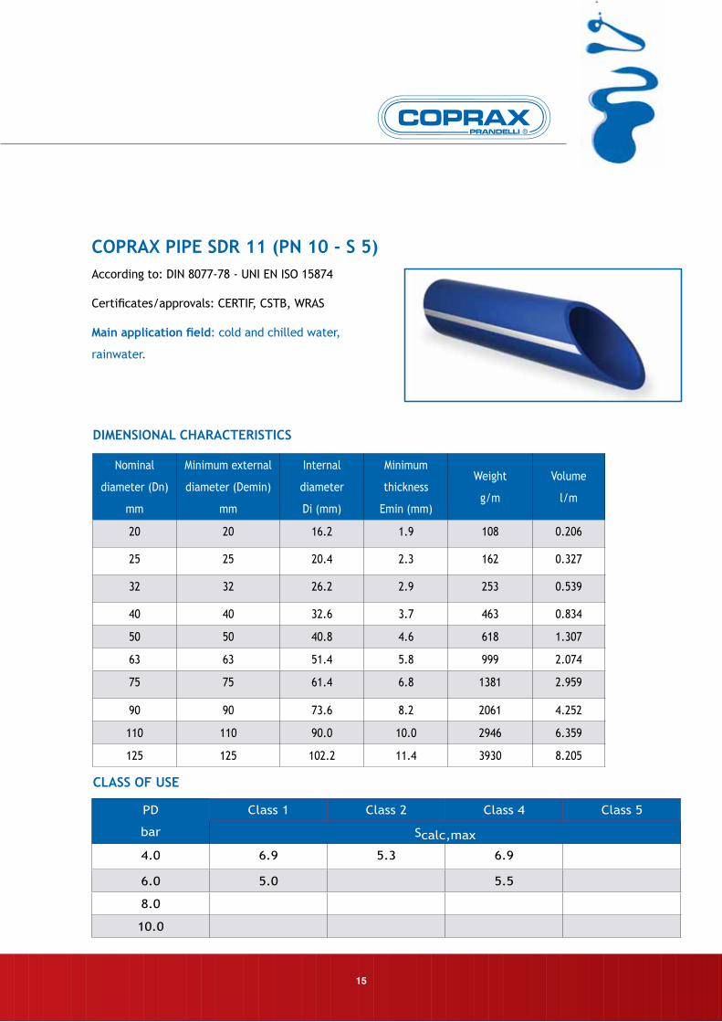
Nominal
diameter (Dn)
mm
Minimum external
diameter (Demin)
mm
Internal
diameter
Di (mm)
Minimum
thickness
Emin (mm)
Weight
g/m
Volume
l/m
20 20 16.2 1.9 108 0.206
25 25 20.4 2.3 162 0.327
32 32 26.2 2.9 253 0.539
40 40 32.6 3.7 463 0.834
50 50 40.8 4.6 618 1.307
63 63 51.4 5.8 999 2.074
75 75 61.4 6.8 1381 2.959
90 90 73.6 8.2 2061 4.252
110 110 90.0 10.0 2946 6.359
125 125 102.2 11.4 3930 8.205
According to: DIN 8077-78 - UNI EN ISO 15874
Certificates/approvals: CERTIF, CSTB, WRAS
main application field: cold and chilled water,
rainwater.
COPRAX PIPe SDR 11 (Pn 10 - S 5)
ClASS OF uSe
DImenSIOnAl CHARACTeRISTICS
PD
bar
Class 1 Class 2 Class 4 Class 5
Scalc,max
4.0 6.9 5.3 6.9
6.0 5.0 5.5
8.0
10.0
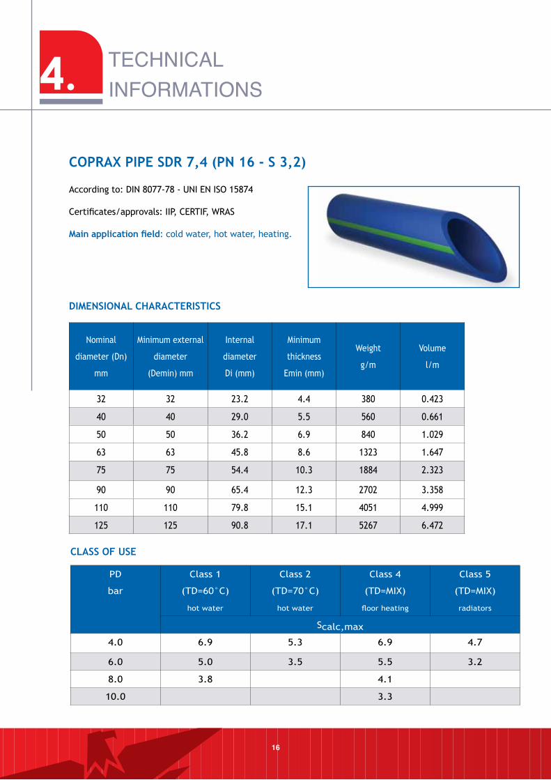
Nominal
diameter (Dn)
mm
Minimum external
diameter
(Demin) mm
Internal
diameter
Di (mm)
Minimum
thickness
Emin (mm)
Weight
g/m
Volume
l/m
32 32 23.2 4.4 380 0.423
40 40 29.0 5.5 560 0.661
50 50 36.2 6.9 840 1.029
63 63 45.8 8.6 1323 1.647
75 75 54.4 10.3 1884 2.323
90 90 65.4 12.3 2702 3.358
110 110 79.8 15.1 4051 4.999
125 125 90.8 17.1 5267 6.472
According to: DIN 8077-78 - UNI EN ISO 15874
Certificates/approvals: IIP, CERTIF, WRAS
main application field: cold water, hot water, heating.
COPRAX PIPe SDR 7,4 (Pn 16 - S 3,2)
ClASS OF uSe
DImenSIOnAl CHARACTeRISTICS
16
PD
bar
Class 1
(TD=60°C)
hot water
Class 2
(TD=70°C)
hot water
Class 4
(TD=MIX)
floor heating
Class 5
(TD=MIX)
radiators
Scalc,max
4.0 6.9 5.3 6.9 4.7
6.0 5.0 3.5 5.5 3.2
8.0 3.8 4.1
10.0 3.3
4. TECHNICALINFORMATIONS
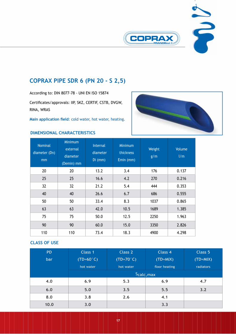
Nominal
diameter (Dn)
mm
Minimum
external
diameter
(Demin) mm
Internal
diameter
Di (mm)
Minimum
thickness
Emin (mm)
Weight
g/m
Volume
l/m
20 20 13.2 3.4 176 0.137
25 25 16.6 4.2 270 0.216
32 32 21.2 5.4 444 0.353
40 40 26.6 6.7 686 0.555
50 50 33.4 8.3 1037 0.865
63 63 42.0 10.5 1689 1.385
75 75 50.0 12.5 2250 1.963
90 90 60.0 15.0 3350 2.826
110 110 73.4 18.3 4900 4.298
According to: DIN 8077-78 - UNI EN ISO 15874
Certificates/approvals: IIP, SKZ, CERTIF, CSTB, DVGW,
RINA, WRAS
main application field: cold water, hot water, heating.
COPRAX PIPe SDR 6 (Pn 20 - S 2,5)
ClASS OF uSe
DImenSIOnAl CHARACTeRISTICS
PD
bar
Class 1
(TD=60°C)
hot water
Class 2
(TD=70°C)
hot water
Class 4
(TD=MIX)
floor heating
Class 5
(TD=MIX)
radiators
Scalc,max
4.0 6.9 5.3 6.9 4.7
6.0 5.0 3.5 5.5 3.2
8.0 3.8 2.6 4.1
10.0 3.0 3.3
17
18
4. TECHNICALINFORMATIONS
Nominal
diameter (Dn)
mm
Minimum
external
diameter
(Demin) mm
Internal
diameter
Di (mm)
Minimum
thickness
Emin (mm)
Weight
g/m
Volume
l/m
20 20 14.4 2.8 146.2 0.163
25 25 18.0 3.5 228.3 0.254
32 32 23.2 4.4 368.6 0.423
40 40 29.0 5.5 575.2 0.660
50 50 36.2 6.9 901.4 1.029
63 63 45.8 8.6 1417.8 1.647
75 75 54.4 10.3 2020.4 2.323
90 90 65.4 12.3 2897.6 3.358
110 110 79.8 15.1 4343.6 4.999
125 125 90.8 17.1 5204.5 6.472
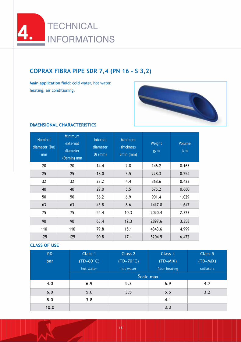
main application field: cold water, hot water,
heating, air conditioning.
COPRAX FIBRA PIPe SDR 7,4 (Pn 16 - S 3,2)
ClASS OF uSe
DImenSIOnAl CHARACTeRISTICS
PD
bar
Class 1
(TD=60°C)
hot water
Class 2
(TD=70°C)
hot water
Class 4
(TD=MIX)
floor heating
Class 5
(TD=MIX)
radiators
Scalc,max
4.0 6.9 5.3 6.9 4.7
6.0 5.0 3.5 5.5 3.2
8.0 3.8 4.1
10.0 3.3
19
Nominal
diameter (Dn)
mm
Minimum
external
diameter
(Demin) mm
Internal
diameter
Di (mm)
Minimum
thickness
Emin (mm)
Weight
g/m
Volume
l/m
40 40 32.6 3.7 407.2 0.834
50 50 40.8 4.6 633.3 1.307
63 63 51.4 5.8 1005.4 2.074
75 75 61.4 6.8 1405.6 2.959
90 90 73.6 8.2 2033.4 4.252
110 110 90.0 10 3031.2 6.359
125 125 102.2 11.4 3925.6 8.203
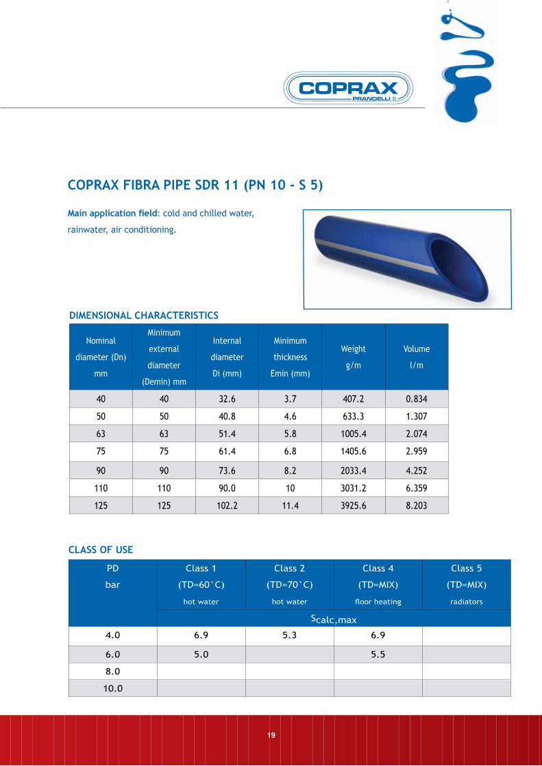
main application field: cold and chilled water,
rainwater, air conditioning.
COPRAX FIBRA PIPe SDR 11 (Pn 10 - S 5)
ClASS OF uSe
DImenSIOnAl CHARACTeRISTICS
PD
bar
Class 1
(TD=60°C)
hot water
Class 2
(TD=70°C)
hot water
Class 4
(TD=MIX)
floor heating
Class 5
(TD=MIX)
radiators
Scalc,max
4.0 6.9 5.3 6.9
6.0 5.0 5.5
8.0
10.0
5. GUARANTEE
The following guarantee is provided for the
COPRAX system when used for heating and wa-
ter supply installations, in a manner compati-
ble with the technical characteristics of the
product and in accordance with the related
installation instructions:
1. Through insurance cover with a leading in-
surance company, Prandelli, manufacturer of
the COPRAX system, will compensate injury
or damage caused by breakage of pipes and
fittings due to obvious manufacturing defects
up to a maximum of € 2.000.000,00, for a
period of 10 YeARS after the date marked
on the pipe.
2. The conditions regulating this guarantee
are as follows:
• the pipe and fittings must be installed in
accordance with the installation instruc-
tions provided by us, further to checking
for possible faults or tampering with which
have occurred after production due to ac-
cidental causes.
• The working conditions (pressure and tem-
perature) must be within the technical li-
mits stated by the latest COPRAX Guide.
• The product must carry the COPRAX iden-
tification mark
3. The guarantee DOeS nOT APPlY in the fol-
lowing cases:
• failure to comply with our installation
instructions and recommendations.
• Connection of the pipe and fittings to heat
sources with temperature and pressure
limits not compatible, even accidentally,
with the characteristics of the pipe and
fittings.
• Use of obviously unsuitable material
(pipes and fittings which are worn out,
old, scratched, etc.)
• Use of one or more components not
manufactured by us in the construction of
the system.
• Poor welds produced using unsuitable
equipment.
20
4. Instructions for requesting after sales
service under guarantee.
In case of damage to the COPRAX system due
solely to obvious manufacturing defects, users
must send us a registered letter, sending a copy
to their local agent. This letter must contain:
• date and place of installation;
• specifications and identification mark of the
pipe and fittings
• information about the working conditions
(pressure and temperature);
• sample of the pipe or fitting on which the
damage has occurred;
• name and address of the installer who
constructed the system.
We will send a technician to check the causes of
the damage within a reasonable period of time
after receipt of the aforesaid registered letter.
If the damage is covered by the terms and
conditions of the GUARANTEE, we will put the
matter in the hands of our insurance company,
and they will pay out compensation after
checking the cause and amount of the damage.
If the damage is not covered by the GUARANTEE,
we will charge the expenses we have incurred to
the customer.
Prandelli S.p.A.
21
6. INSTRUCTIONS FOR USE
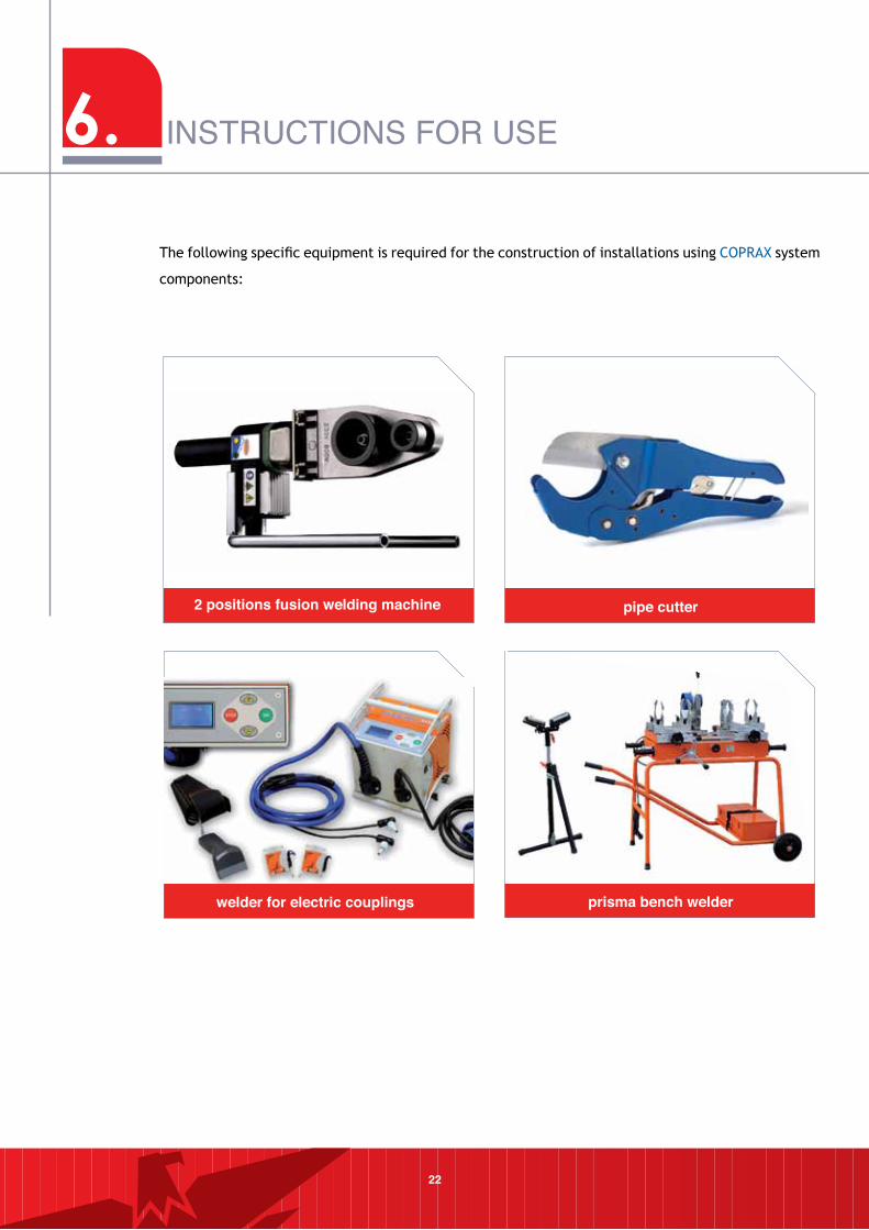
22
2 positions fusion welding machine pipe cutter
welder for electric couplings prisma bench welder
The following specific equipment is required for the construction of installations using COPRAX system
components:
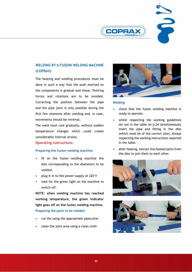
WelDInG BY A FuSIOn WelDInG mACHIne
(COPRAX)
The heating and welding procedures must be
done in such a way that the push exerted on
the components is gradual and linear. Twisting
forces and rotations are to be avoided.
Correcting the position between the pipe
and the pipe joint is only possible during the
first few moments after welding and, in case,
movements should be minimal.
The weld must cool gradually, without sudden
temperature changes which could create
considerable internal strains.
Operating instructions:
Preparing the fusion welding machine
• fit on the fusion welding machine the
dies corresponding to the diameters to be
welded.
• plug it in to the power supply at 220 V
• wait for the green light on the machine to
switch off.
nOTe: when welding machine has reached
working temperature, the green indicator
light goes off on the fusion welding machine.
Preparing the parts to be welded
• cut the using the appropriate pipecutter
• clean the joint area using a clean cloth
•
Welding
• check that the fusion welding machine is ready to operate.
• whilst respecting the working guidelines set out in the table on p.24 simultaneously insert the pipe and fitting in the dies (which must be of the correct size), always respecting the working instructions reported in the table.
• after heating, extract the heated parts from the dies to join them to each other.
23
6. INSTRUCTIONS FOR USE
24
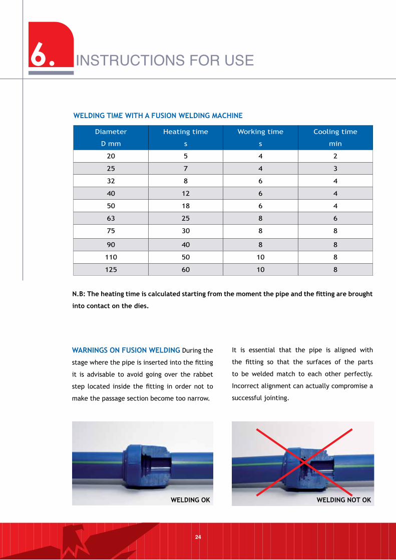
n.B: The heating time is calculated starting from the moment the pipe and the fitting are brought
into contact on the dies.
WARnInGS On FuSIOn WelDInG During the
stage where the pipe is inserted into the fitting
it is advisable to avoid going over the rabbet
step located inside the fitting in order not to
make the passage section become too narrow.
It is essential that the pipe is aligned with
the fitting so that the surfaces of the parts
to be welded match to each other perfectly.
Incorrect alignment can actually compromise a
successful jointing.
WelDInG TIme WITH A FuSIOn WelDInG mACHIne
Diameter
D mm
Heating time
s
Working time
s
Cooling time
min
20 5 4 2
25 7 4 3
32 8 6 4
40 12 6 4
50 18 6 4
63 25 8 6
75 30 8 8
90 40 8 8
110 50 10 8
125 60 10 8
WelDInG OK WelDInG nOT OK
25
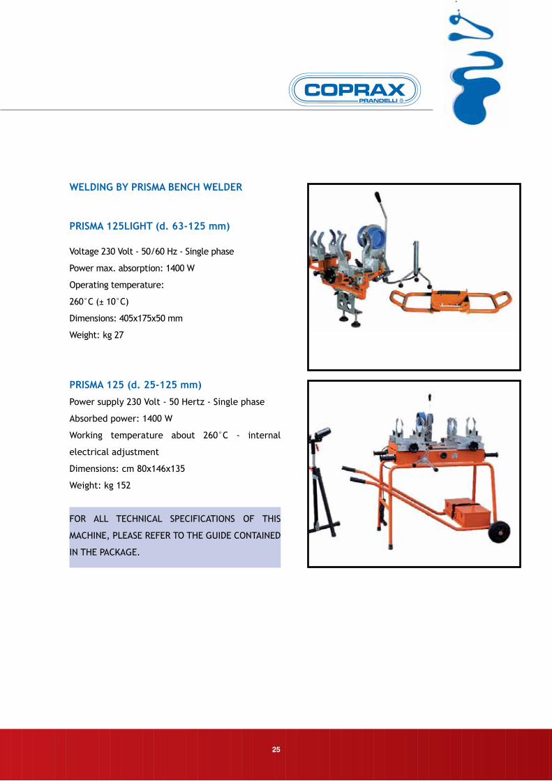
WelDInG BY PRISmA BenCH WelDeR
PRISmA 125lIGHT (d. 63-125 mm)
Voltage 230 Volt - 50/60 Hz - Single phase
Power max. absorption: 1400 W
Operating temperature:
260°C (± 10°C)
Dimensions: 405x175x50 mm
Weight: kg 27
PRISmA 125 (d. 25-125 mm)
Power supply 230 Volt - 50 Hertz - Single phase
Absorbed power: 1400 W
Working temperature about 260°C - internal
electrical adjustment
Dimensions: cm 80x146x135
Weight: kg 152
FOR ALL TECHNICAL SPECIFICATIONS OF THIS
MACHINE, PLEASE REFER TO THE GUIDE CONTAINED
IN THE PACKAGE.
6. INSTRUCTIONS FOR USE
26
WelDInG uSInG An eleCTRIC COuPlInG
WelDInG mACHIne
Electric coupling welding is particularly
recommended to carry out repairs or welding
on parts already installed.
Operating instructions:
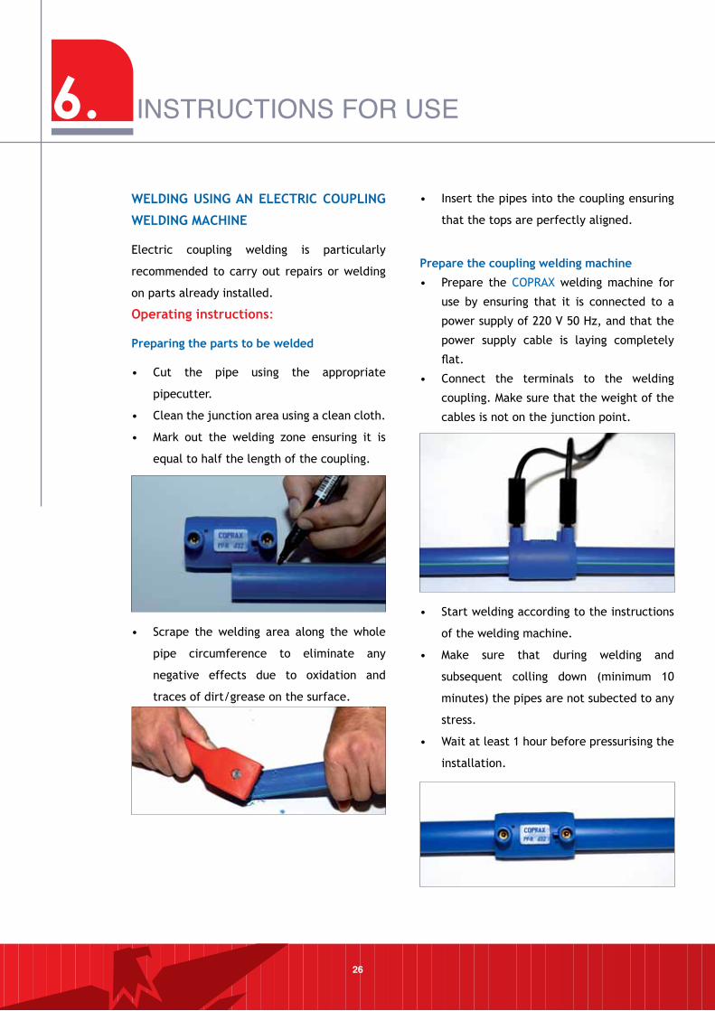
Preparing the parts to be welded
• Cut the pipe using the appropriate
pipecutter.
• Clean the junction area using a clean cloth.
• Mark out the welding zone ensuring it is
equal to half the length of the coupling.
• Scrape the welding area along the whole
pipe circumference to eliminate any
negative effects due to oxidation and
traces of dirt/grease on the surface.
• Insert the pipes into the coupling ensuring
that the tops are perfectly aligned.
Prepare the coupling welding machine
• Prepare the COPRAX welding machine for
use by ensuring that it is connected to a
power supply of 220 V 50 Hz, and that the
power supply cable is laying completely
flat.
• Connect the terminals to the welding
coupling. Make sure that the weight of the
cables is not on the junction point.
• Start welding according to the instructions
of the welding machine.
• Make sure that during welding and
subsequent colling down (minimum 10
minutes) the pipes are not subected to any
stress.
• Wait at least 1 hour before pressurising the
installation.
27
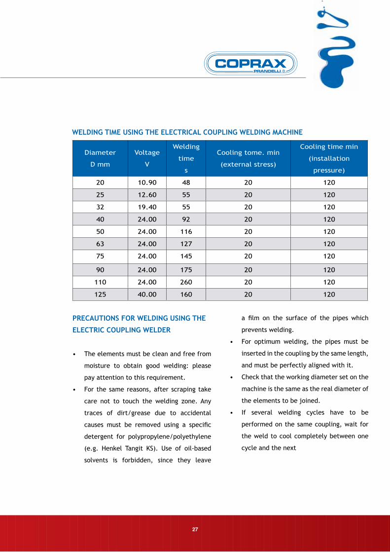
WelDInG TIme uSInG THe eleCTRICAl COuPlInG WelDInG mACHIne
Diameter
D mm
Voltage
V
Welding
time
s
Cooling tome. min
(external stress)
Cooling time min
(installation
pressure)
20 10.90 48 20 120
25 12.60 55 20 120
32 19.40 55 20 120
40 24.00 92 20 120
50 24.00 116 20 120
63 24.00 127 20 120
75 24.00 145 20 120
90 24.00 175 20 120
110 24.00 260 20 120
125 40.00 160 20 120
PReCAuTIOnS FOR WelDInG uSInG THe
eleCTRIC COuPlInG WelDeR
• The elements must be clean and free from
moisture to obtain good welding: please
pay attention to this requirement.
• For the same reasons, after scraping take
care not to touch the welding zone. Any
traces of dirt/grease due to accidental
causes must be removed using a specific
detergent for polypropylene/polyethylene
(e.g. Henkel Tangit KS). Use of oil-based
solvents is forbidden, since they leave
a film on the surface of the pipes which
prevents welding.
• For optimum welding, the pipes must be
inserted in the coupling by the same length,
and must be perfectly aligned with it.
• Check that the working diameter set on the
machine is the same as the real diameter of
the elements to be joined.
• If several welding cycles have to be
performed on the same coupling, wait for
the weld to cool completely between one
cycle and the next
6. INSTRUCTIONS FOR USE
28
WelDInG uSInG SADDle FITTInGS (K47)
The K47 saddle fitting can prove to be extremely
useful for the installer as it enables union joints
to be obtained in a practical and reliable way on
segments of previously installed pipes and enables
the joints to have a larger diameter compared to the
requirements of the new users to be activated. In
order to perform the necessary welding operations,
using fusion welding machine matrices having the
correct geometry is essential to achieve perfect
fusion of the surfaces to be welded to each other.
Here is a summary of the operating stages for the
correct use of the K47 saddle fitting.
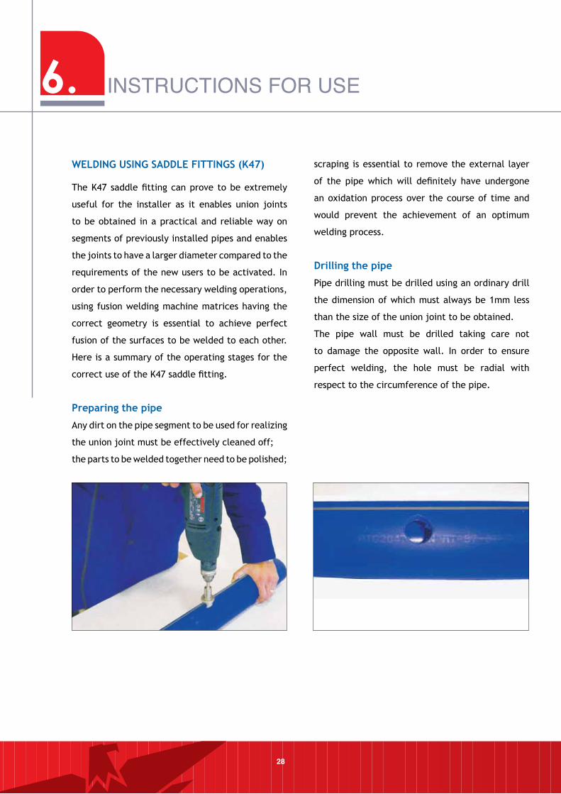
Preparing the pipe
Any dirt on the pipe segment to be used for realizing
the union joint must be effectively cleaned off;
the parts to be welded together need to be polished;
scraping is essential to remove the external layer
of the pipe which will definitely have undergone
an oxidation process over the course of time and
would prevent the achievement of an optimum
welding process.
Drilling the pipe
Pipe drilling must be drilled using an ordinary drill
the dimension of which must always be 1mm less
than the size of the union joint to be obtained.
The pipe wall must be drilled taking care not
to damage the opposite wall. In order to ensure
perfect welding, the hole must be radial with
respect to the circumference of the pipe.
29
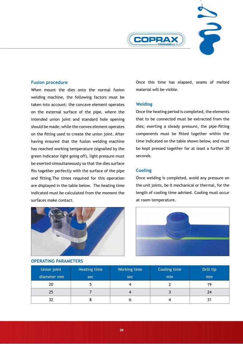
OPeRATInG PARAmeTeRS
Union joint
diameter mm
Heating time
sec
Working time
sec
Cooling time
min
Drill tip
mm
20 5 4 2 19
25 7 4 3 24
32 8 6 4 31
Fusion procedure
When mount the dies onto the normal fusion
welding machine, the following factors must be
taken into account: the concave element operates
on the external surface of the pipe, where the
intended union joint and standard hole opening
should be made; while the convex element operates
on the fitting used to create the union joint. After
having ensured that the fusion welding machine
has reached working temperature (signalled by the
green indicator light going off), light pressure must
be exerted simoultaneously so that the dies surface
fits together perfectly with the surface of the pipe
and fitting.The times required for this operation
are displayed in the table below. The heating time
indicated must be calculated from the moment the
surfaces make contact.
Once this time has elapsed, seams of melted
material will be visible.
Welding
Once the heating period is completed, the elements
that to be connected must be extracted from the
dies; exerting a steady pressure, the pipe-fitting
components must be fitted together within the
time indicated on the table shown below, and must
be kept pressed together for at least a further 30
seconds.
Cooling
Once welding is completed, avoid any pressure on
the unit joints, be it mechanical or thermal, for the
length of cooling time advised. Cooling must occur
at room temperature.
6. INSTRUCTIONS FOR USE
30
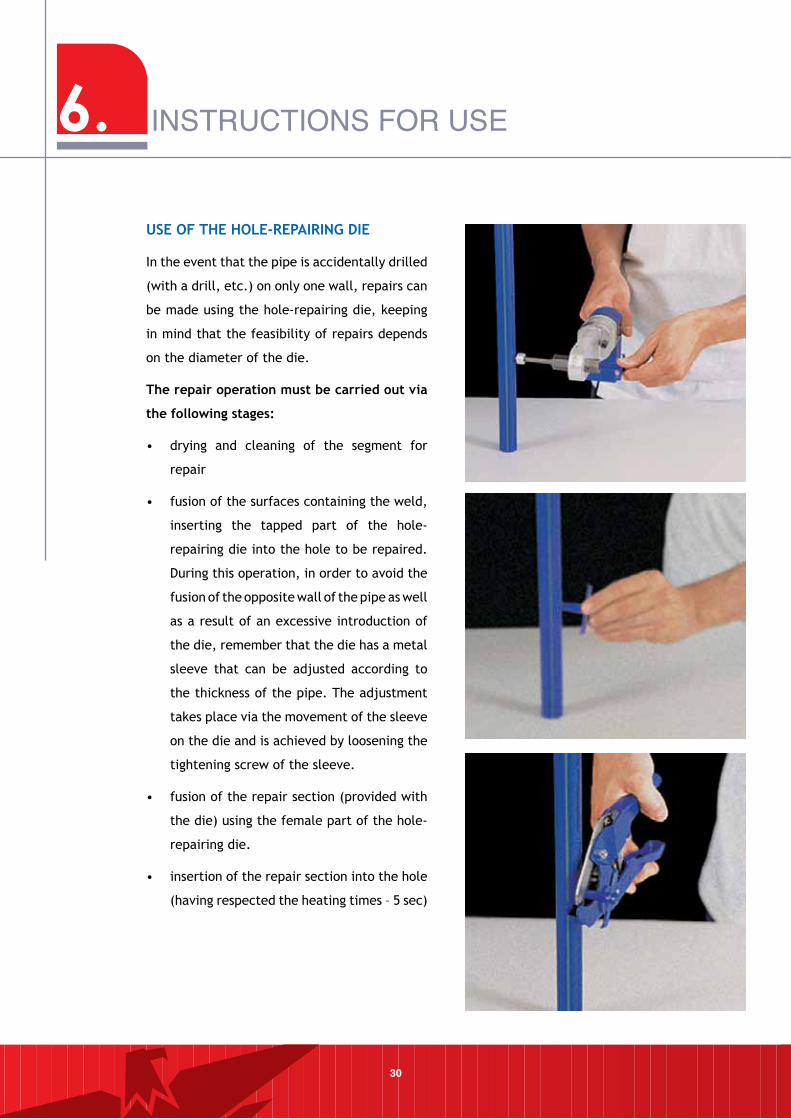
uSe OF THe HOle-RePAIRInG DIe
In the event that the pipe is accidentally drilled
(with a drill, etc.) on only one wall, repairs can
be made using the hole-repairing die, keeping
in mind that the feasibility of repairs depends
on the diameter of the die.
The repair operation must be carried out via
the following stages:
• drying and cleaning of the segment for
repair
• fusion of the surfaces containing the weld,
inserting the tapped part of the hole-
repairing die into the hole to be repaired.
During this operation, in order to avoid the
fusion of the opposite wall of the pipe as well
as a result of an excessive introduction of
the die, remember that the die has a metal
sleeve that can be adjusted according to
the thickness of the pipe. The adjustment
takes place via the movement of the sleeve
on the die and is achieved by loosening the
tightening screw of the sleeve.
• fusion of the repair section (provided with
the die) using the female part of the hole-
repairing die.
• insertion of the repair section into the hole
(having respected the heating times – 5 sec)
31
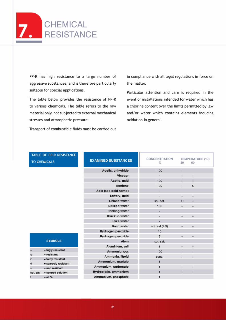
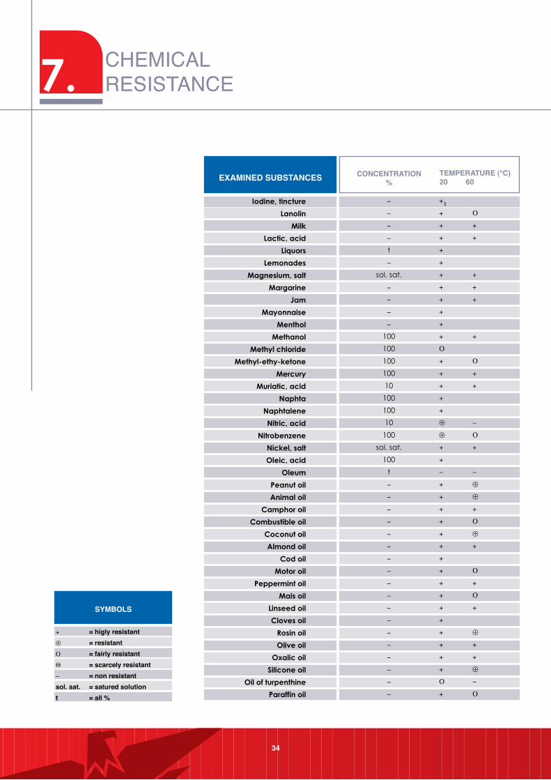
EXAMINED SUBSTANCES CONCENTRATION %
100-
100100
--
sol. sat. 100
---
sol. sat.(4.9)103
sol. sat. t
100conc.
tttt
+
+ +
+ +
+ O
+ +
O -
+ +
+ +
+ +
+ +
+ +
+ +
+ +
+ +
+ +
TEMPERATURE (°C)20 60
SYMBOLS
+ = higly resistant⊕ = resistantO = fairly resistantQ = scarcely resistant- = non resistantsol. sat. = satured solutiont = all %
PP-R has high resistance to a large number of
aggressive substances, and is therefore particularly
suitable for special applications.
The table below provides the resistance of PP-R
to various chemicals. The table refers to the raw
material only, not subjected to external mechanical
stresses and atmospheric pressure.
Transport of combustible fluids must be carried out
in compliance with all legal regulations in force on
the matter.
Particular attention and care is required in the
event of installations intended for water which has
a chlorine content over the limits permitted by law
and/or water which contains elements inducing
oxidation in general.
TABle OF PP-R ReSISTAnCe
TO CHemICAlS
7. CHEMICALRESISTANCE
7.
32
CHEMICALRESISTANCE
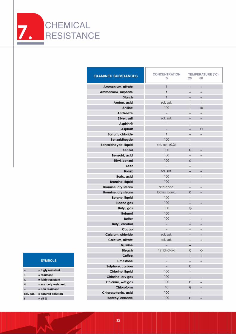
EXAMINED SUBSTANCES CONCENTRATION %
+ +
+ +
+ +
+ +
+ ⊕
+ +
+ +
+
+ O
+ +
+
+
Q -
+ +
O -
+
+ +
+ +
-
- -
O -
+
+ +
⊕
+
+ +
+ +
+ +
+ +
+ +
+
O O
+ +
+ +
O
-
- -
O -
Q -
- -
Q -
TEMPERATURE (°C)20 60
SYMBOLS
+ = higly resistant⊕ = resistantO = fairly resistantQ = scarcely resistant- = non resistantsol. sat. = satured solutiont = all %
33
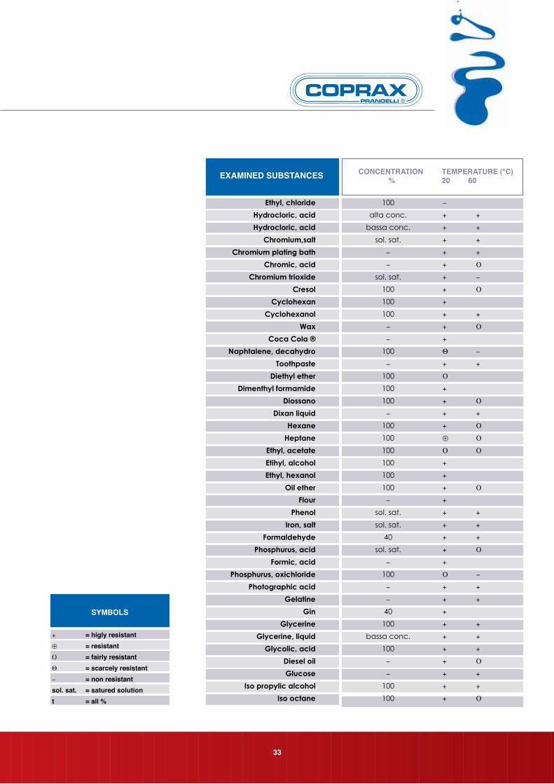
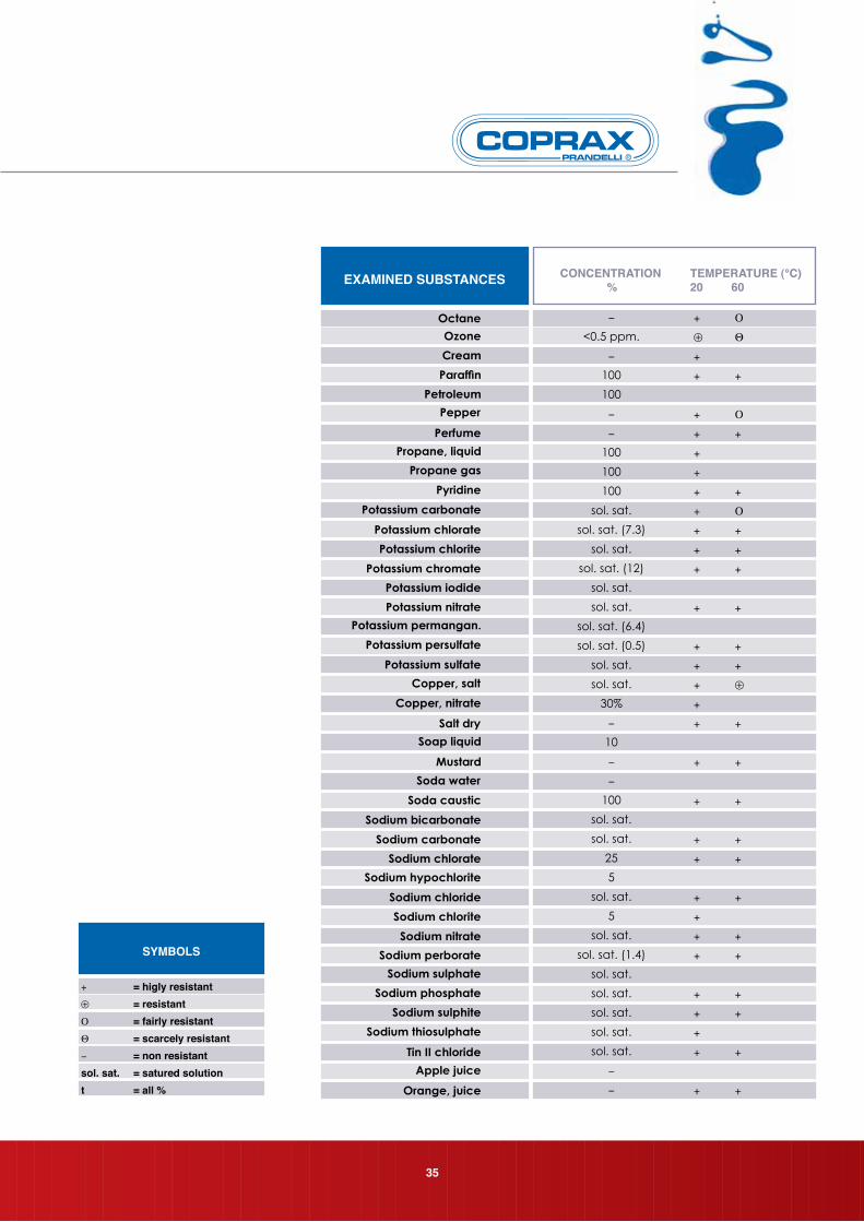
EXAMINED SUBSTANCES CONCENTRATION %
TEMPERATURE (°C)20 60
SYMBOLS
+ = higly resistant⊕ = resistantO = fairly resistantQ = scarcely resistant- = non resistantsol. sat. = satured solutiont = all %
7. CHEMICALRESISTANCE
34
TEMPERATURE (°C)20 60 EXAMINED SUBSTANCES CONCENTRATION
%
SYMBOLS
+ = higly resistant⊕ = resistantO = fairly resistantQ = scarcely resistant- = non resistantsol. sat. = satured solutiont = all %
35
+ O
⊕ Q
+
+ +
+ O
+ +
+
+
+ +
+ O
+ +
+ +
+ +
+ +
+ +
+ +
+ ⊕
+
+ +
+ +
+ +
+ +
+ +
+ +
+
+ +
+ +
+ +
+ +
+
+ +
+ +
EXAMINED SUBSTANCES CONCENTRATION %
TEMPERATURE (°C)20 60
SYMBOLS
+ = higly resistant⊕ = resistantO = fairly resistantQ = scarcely resistant- = non resistantsol. sat. = satured solutiont = all %
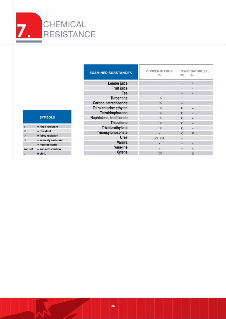
7. CHEMICALRESISTANCE
36
+ +
+ +
+ +
-
Q -
O -
O -
O -
O -
O Q
+
+ +
+ +
+ O
TEMPERATURE (°C)20 60 EXAMINED SUBSTANCES CONCENTRATION
%
SYMBOLS
+ = higly resistant⊕ = resistantO = fairly resistantQ = scarcely resistant- = non resistantsol. sat. = satured solutiont = all %
8. PRESSURE LOSS
Calculation of pressure loss is a fundamental step in
the design of heating and water supply systems. This
parameter is closely linked to the delivery rate of
the system, i.e. the amount of water which reaches
the individual users within a unit of time.
Pressure loss may be continuous or localised. The
sum of these two components provides the total
pressure loss of the system.
Continuous loss of pressure is generated by the
continuous resistance which a fluid encounters as it
flows along a pipe. Such resistance consist of the
internal friction of the fluid itself, due to viscosity,
and resistance generated by contact with the inside
surface of the pipe.
Continuous loss of pressure is measured in pressure
units (pascal, bar, metres or millimetres of water
column); in general, the measurement refers to a
unit length of pipe.
In the specific case of COPRAX system pipes, the
continuous loss of pressure is determined by means
of the graphs given on the facing page (measured
with water at 20°C).
37
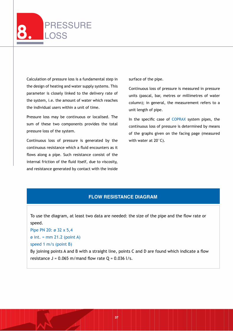
To use the diagram, at least two data are needed: the size of the pipe and the flow rate or
speed.
Pipe PN 20: ø 32 x 5,4
ø int. = mm 21.2 (point A)
speed 1 m/s (point B)
By joining points A and B with a straight line, points C and D are found which indicate a flow
resistance J = 0.065 m/mand flow rate Q = 0.036 l/s.
FLOW RESISTANCE DIAGRAM
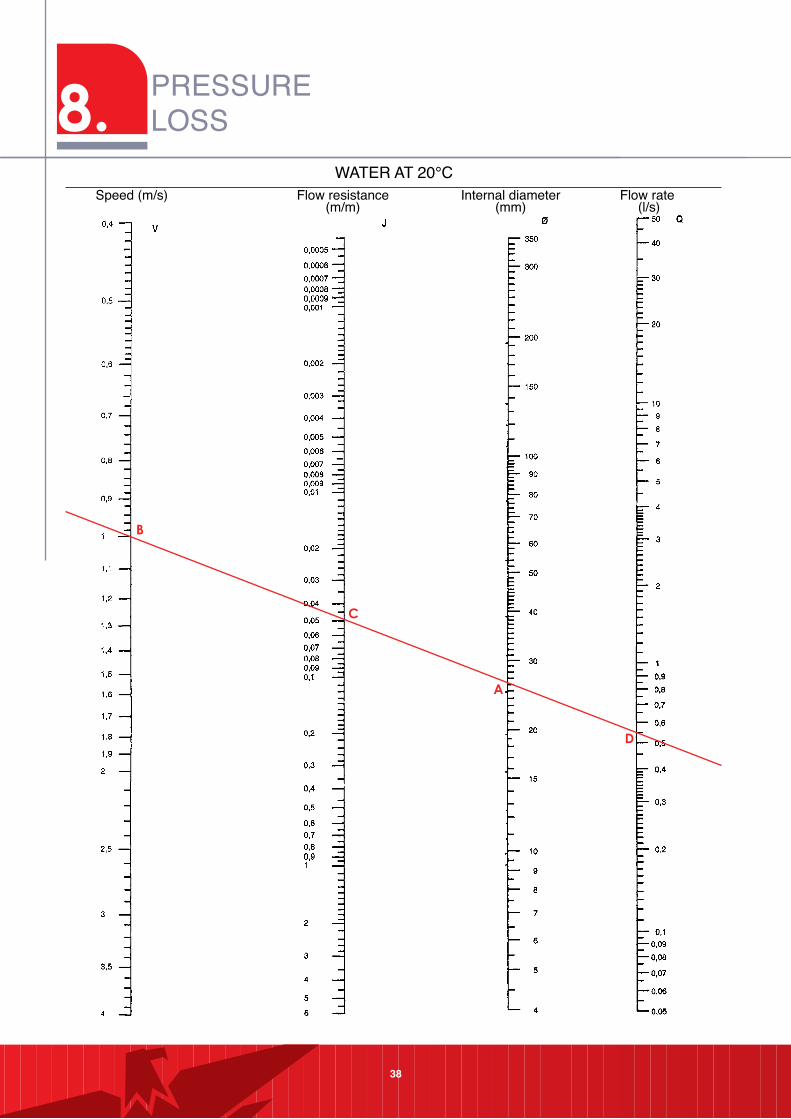
38
WATER AT 20°CSpeed (m/s) Flow resistance
(m/m)Internal diameter
(mm)Flow rate
(l/s)
8. PRESSURELOSS

39
WATER AT 60°CSpeed (m/s) Flow resistance
(m/m)Internal diameter
(mm)Flow rate
(l/s)
40
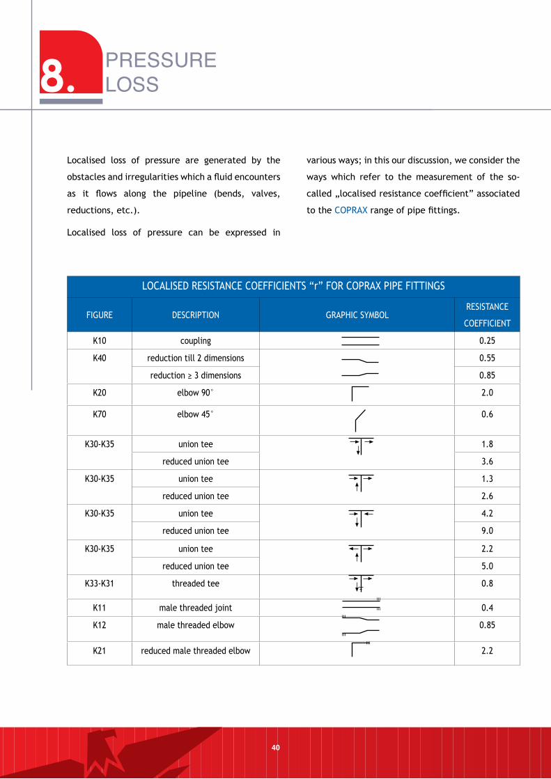
Localised loss of pressure are generated by the
obstacles and irregularities which a fluid encounters
as it flows along the pipeline (bends, valves,
reductions, etc.).
Localised loss of pressure can be expressed in
various ways; in this our discussion, we consider the
ways which refer to the measurement of the so-
called „localised resistance coefficient” associated
to the COPRAX range of pipe fittings.
8. PRESSURE LOSS
LOCALISED RESISTANCE COEFFICIENTS “r” FOR COPRAX PIPE FITTINGS
FIGURE DESCRIPTION GRAPHIC SYMBOLRESISTANCE
COEFFICIENT
K10 coupling 0.25
K40 reduction till 2 dimensions 0.55
reduction ≥ 3 dimensions 0.85
K20 elbow 90° 2.0
K70 elbow 45° 0.6
K30-K35 union tee 1.8
reduced union tee 3.6
K30-K35 union tee 1.3
reduced union tee 2.6
K30-K35 union tee 4.2
reduced union tee 9.0
K30-K35 union tee 2.2
reduced union tee 5.0
K33-K31 threaded tee 0.8
K11 male threaded joint 0.4
K12 male threaded elbow 0.85
K21 reduced male threaded elbow 2.2
41
lOSS OF PReSSuRe z In RelATIOn TO
R=1 W/WATeR AT 10°C FOR VARIOuS
SPeeDS V
FLOWING SPEED v
(m/s)
LOSS OF PRESSURE z FOR r=1 (mbar)
LOSS OF PRESSURE z FOR r=1 (mbar)
33.836.539.242.1454851555861656872768084889297101106110115120125
2.62.72.82.93.03.13.23.33.43.53.63.73.83.94.04.14.24.34.44.54.64.74.84.95.0
0.10.20.50.81.31.82.53.24.15.06.17.28.59.811.312.814.516.218.120.022.124.226.528.831.3
0.10.20.30.40.50.60.70.80.91.01.11.21.31.41.51.61.71.81.92.02.12.22.32.42.5
Once the coefficients „r” are known, the system’s
localised loss of pressure are calculated using the
following formula:
(mbar)
where:
= 999.7 kg/m3 specific weight of water
g = 9.81 m/s2 gravity acceleration
v = speed of water in m/s
= summation
FLOWING SPEED v
(m/s)
42
8. PRESSURELOSS
TOTAl lOSS OF PReSSuRe
As already mentioned, the total system pressure
loss is obtained by adding together the continuous
and localised loss of pressure:
∆P = l • R + z • 10 where:
∆P = total loss of pressure (mm c.a.)
l = pipeline length (m)
R = continuous loss of pressure (mm c.a./m)
z = localised loss of pressure (mbar)
eXPAnSIOn AnD STIRRuPS
Each material which undergoes a variation in
temperature over time reacts by modifying its size
to varying degrees.
This phenomenon is called thermal expansion; the
body will increase in volume when the temperature
rises, or contract when it decreases.
Thermal expansion may be linear, superficial or
cubic, depending on whether it mainly affects one,
two or all three of the body’s dimensions.
In the case of pipelines, the expansion is mainly
linear, since their length far exceeds their other
dimensions.
The parameter which provides guidance on a
pipe’s tendency to expand or contract in case of
a temperature variation is its linear expansion
coefficient.
Therefore, when designing and constructing
installations it is essential to know the value of
this coefficient, in order to correctly calculate the
extent of expansion/contraction and adopt the
necessary measures to ensure that this will not
damage the piping.
Thermal
conductivity of
the insulation
W / m°K
Outer diameter of the pipingmm
<20 da 20 a 39 da 40 a 59 da 60 a 79 da 80 a 99 > 100
0,030 13 19 26 33 37 40
0,032 14 21 29 36 40 44
0,034 15 23 31 39 44 48
0,036 17 25 34 43 47 52
0,038 18 28 37 46 51 56
0,040 20 30 40 50 55 60
0,042 22 32 43 54 59 64
0,044 24 35 46 58 63 69
0,046 26 38 50 62 68 74
0,048 28 41 54 66 72 79
0,050 30 44 58 71 77 84
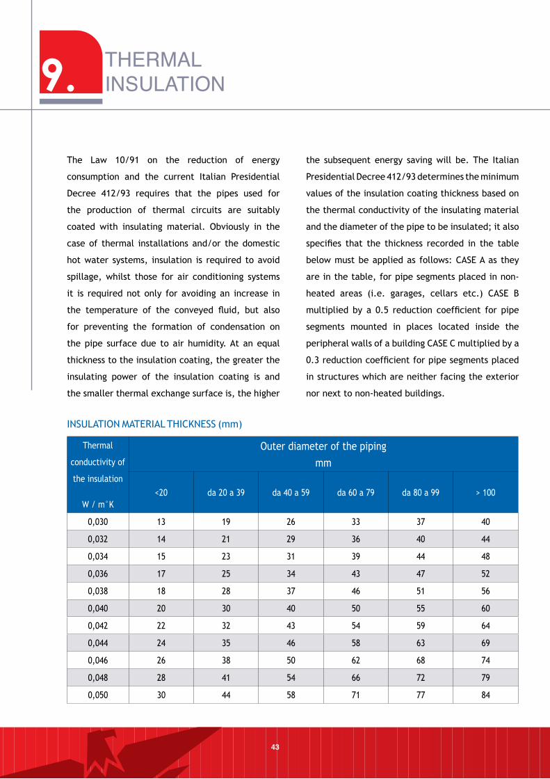
The Law 10/91 on the reduction of energy
consumption and the current Italian Presidential
Decree 412/93 requires that the pipes used for
the production of thermal circuits are suitably
coated with insulating material. Obviously in the
case of thermal installations and/or the domestic
hot water systems, insulation is required to avoid
spillage, whilst those for air conditioning systems
it is required not only for avoiding an increase in
the temperature of the conveyed fluid, but also
for preventing the formation of condensation on
the pipe surface due to air humidity. At an equal
thickness to the insulation coating, the greater the
insulating power of the insulation coating is and
the smaller thermal exchange surface is, the higher
the subsequent energy saving will be. The Italian
Presidential Decree 412/93 determines the minimum
values of the insulation coating thickness based on
the thermal conductivity of the insulating material
and the diameter of the pipe to be insulated; it also
specifies that the thickness recorded in the table
below must be applied as follows: CASE A as they
are in the table, for pipe segments placed in non-
heated areas (i.e. garages, cellars etc.) CASE B
multiplied by a 0.5 reduction coefficient for pipe
segments mounted in places located inside the
peripheral walls of a building CASE C multiplied by a
0.3 reduction coefficient for pipe segments placed
in structures which are neither facing the exterior
nor next to non-heated buildings.
9. THERMAL INSULATION
43
INSULATION MATERIAL THICKNESS (mm)
44
10.TECHNICAL INSTALLATION
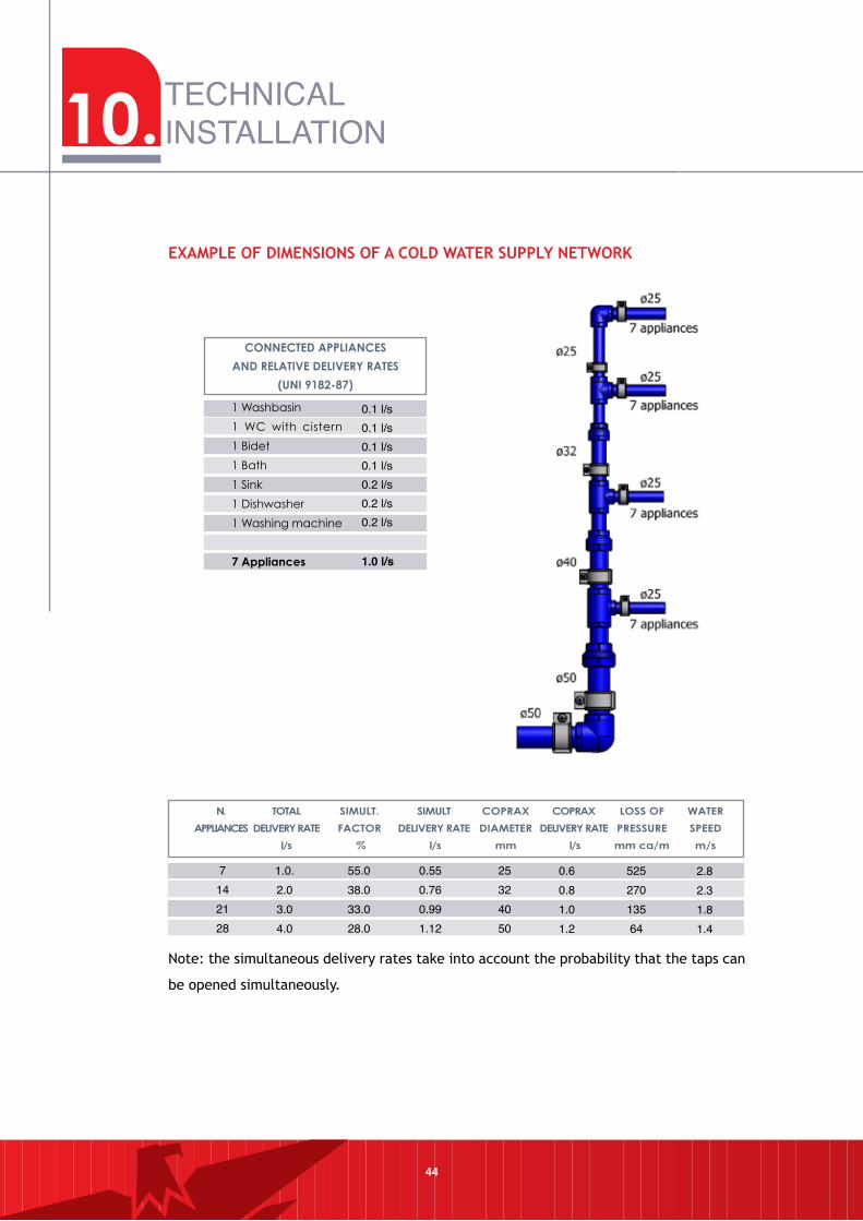
eXAmPle OF DImenSIOnS OF A COlD WATeR SuPPlY neTWORK
0.1 l/s0.1 l/s0.1 l/s0.1 l/s0.2 l/s0.2 l/s0.2 l/s
1.0 l/s
14 a
pplia
nces
21 a
pplia
nces
28 a
pplia
nces
2.82.31.81.4
52527013564
0.60.81.01.2
25324050
0.550.760.991.12
55.038.033.028.0
1.0.2.03.04.0
7142128
Note: the simultaneous delivery rates take into account the probability that the taps can
be opened simultaneously.
45
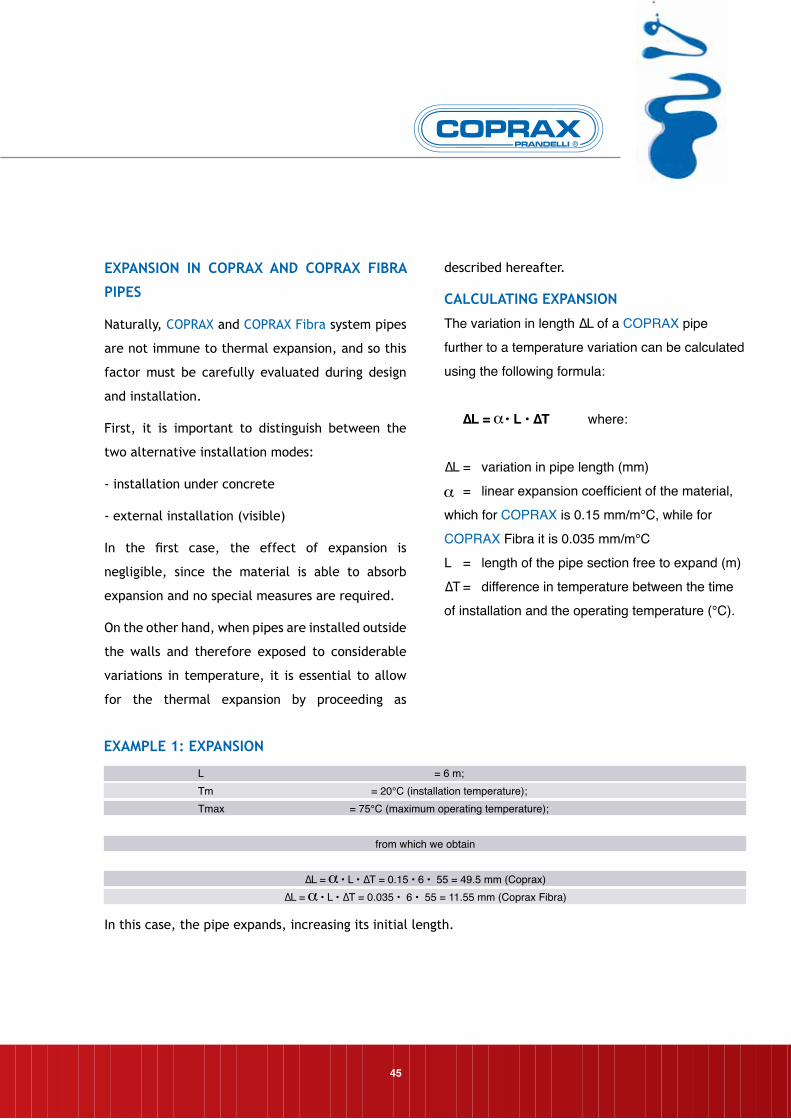
L = 6 m; Tm = 20°C (installation temperature);Tmax = 75°C (maximum operating temperature);
from which we obtain
∆L = • L • ∆T = 0.15 • 6 • 55 = 49.5 mm (Coprax)∆L = • L • ∆T = 0.035 • 6 • 55 = 11.55 mm (Coprax Fibra)
In this case, the pipe expands, increasing its initial length.
eXPAnSIOn In COPRAX AnD COPRAX FIBRA
PIPeS
Naturally, COPRAX and COPRAX Fibra system pipes
are not immune to thermal expansion, and so this
factor must be carefully evaluated during design
and installation.
First, it is important to distinguish between the
two alternative installation modes:
- installation under concrete
- external installation (visible)
In the first case, the effect of expansion is
negligible, since the material is able to absorb
expansion and no special measures are required.
On the other hand, when pipes are installed outside
the walls and therefore exposed to considerable
variations in temperature, it is essential to allow
for the thermal expansion by proceeding as
described hereafter.
CAlCulATInG eXPAnSIOn
The variation in length ∆L of a COPRAX pipe
further to a temperature variation can be calculated
using the following formula:
∆L = • L • ∆T where:
∆L = variation in pipe length (mm)
= linear expansion coefficient of the material,
which for COPRAX is 0.15 mm/m°C, while for
COPRAX Fibra it is 0.035 mm/m°C
L = length of the pipe section free to expand (m)
∆T = difference in temperature between the time
of installation and the operating temperature (°C).
eXAmPle 1: eXPAnSIOn
10.TECHNICALINSTALLATION
46
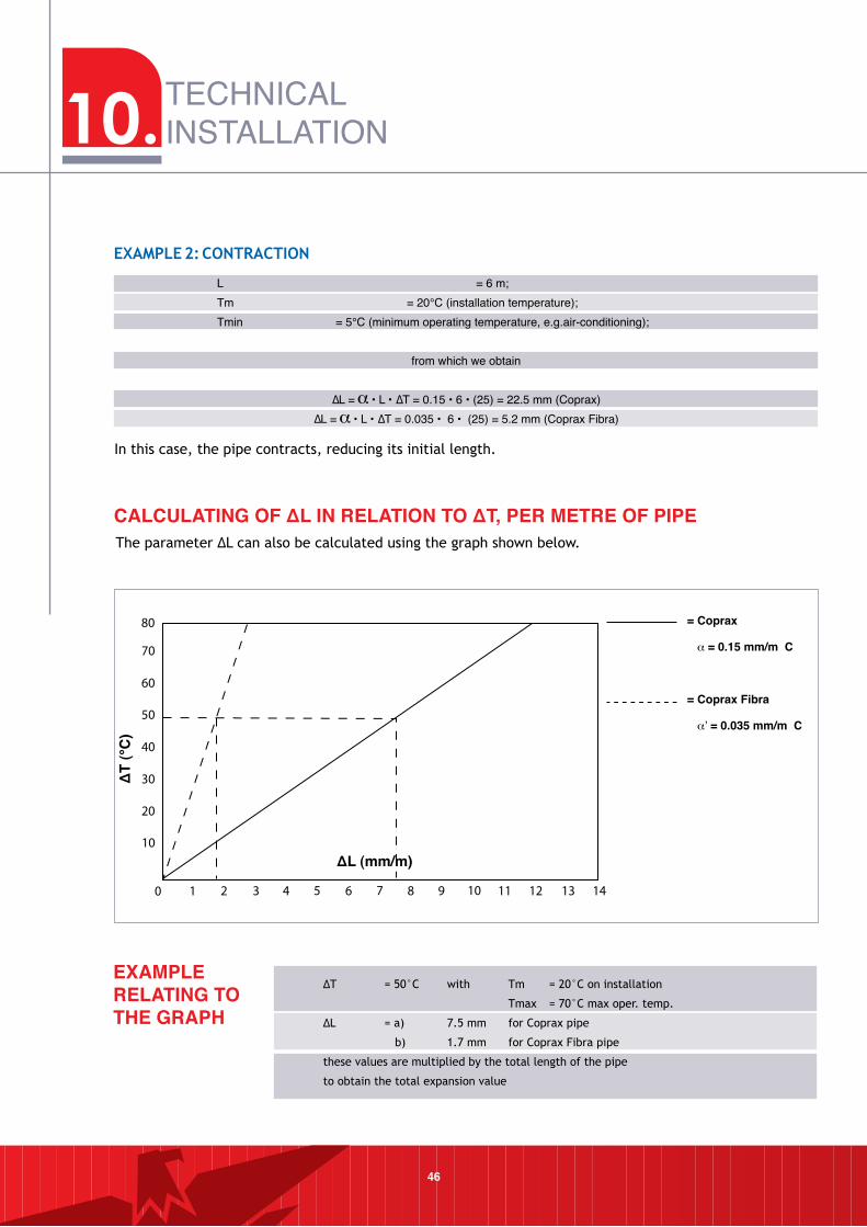
CALCULATING OF ΔL IN RELATION TO ΔT, PER METRE OF PIPEThe parameter ∆L can also be calculated using the graph shown below.
0 1 2 3 4 5 6 7 8 9 10
10
20
30
40
50
60
70
80
11 12 13 14
ΔL (mm/m)
ΔT
(°C
)
= Coprax
α = 0.15 mm/m C
= Coprax Fibra
α’ = 0.035 mm/m C
EXAMPLE RELATING TO THE GRAPH
∆T = 50°C with Tm = 20°C on installation
Tmax = 70°C max oper. temp.
∆L = a) 7.5 mm for Coprax pipe
b) 1.7 mm for Coprax Fibra pipe
these values are multiplied by the total length of the pipe
to obtain the total expansion value
L = 6 m; Tm = 20°C (installation temperature);Tmin = 5°C (minimum operating temperature, e.g.air-conditioning);
from which we obtain
∆L = • L • ∆T = 0.15 • 6 • (25) = 22.5 mm (Coprax)∆L = • L • ∆T = 0.035 • 6 • (25) = 5.2 mm (Coprax Fibra)
In this case, the pipe contracts, reducing its initial length.
eXAmPle 2: COnTRACTIOn
47
InSTAllATIOn TeCHnIQue WHen THeRmAl
eXPAnSIOn IS PReSenT
Once the variation in length of the piping has been
calculated, the necessary measures must be taken
to ensure that its effects do not cause problems
for the piping itself. The following procedures may
be used:
- provision of fixed and sliding points;
- compensation with expansion arms.
FIXeD AnD SlIDInG POInTS
These are fixtures which secure the piping to
the masonry structure of the building, totally or
partially preventing the movements generated by
thermal expansion.
Fixed points prevent pipes from moving, and so
must provide a rigid connection between the
installation and the masonry.
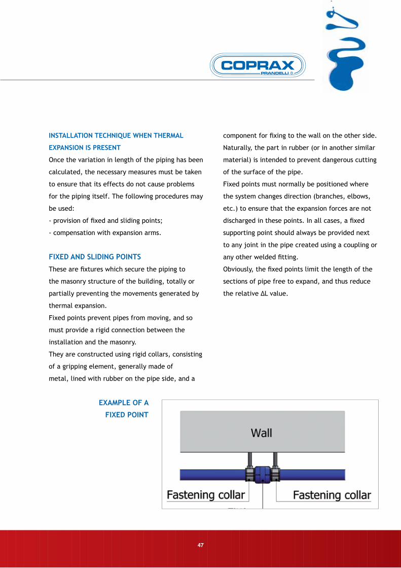
They are constructed using rigid collars, consisting
of a gripping element, generally made of
metal, lined with rubber on the pipe side, and a
component for fixing to the wall on the other side.
Naturally, the part in rubber (or in another similar
material) is intended to prevent dangerous cutting
of the surface of the pipe.
Fixed points must normally be positioned where
the system changes direction (branches, elbows,
etc.) to ensure that the expansion forces are not
discharged in these points. In all cases, a fixed
supporting point should always be provided next
to any joint in the pipe created using a coupling or
any other welded fitting.
Obviously, the fixed points limit the length of the
sections of pipe free to expand, and thus reduce
the relative ∆L value.
eXAmPle OF A
FIXeD POInT
10.TECHNICAL INSTALLATION
48
THe STIRRuP DISTAnCeS
To allow correct installation of COPRAX system pipes
on the outside of walls, the following is the graph
used to calculate the stirrup distances between
points. These distances remain the same regardless
of whether the pipes are horizontal or vertical.
OUTSIDE DIAMETER MM
CLA
MPI
NG
DIS
TAN
CES
IN C
M
Sliding points allow the pipe to move axially in both
directions. They therefore have to be positioned
well away from joints made using pipe fittings, on
a free part of the pipe’s surface. The collar which
forms the sliding support point must be absolutely
free from contact with parts which might damage
the outside surface of the pipe.
Sliding points also provide support and ensure
(provided enough of them are installed) that the
pipe remains straight in spite of thermal stresses.
See „stirrup distances”.
eXAmPle OF
SlIDInG POInT
49
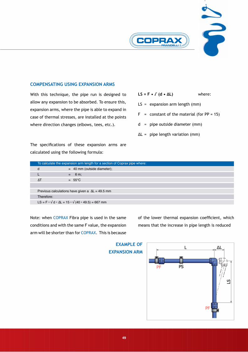
COmPenSATInG uSInG eXPAnSIOn ARmS
With this technique, the pipe run is designed to
allow any expansion to be absorbed. To ensure this,
expansion arms, where the pipe is able to expand in
case of thermal stresses, are installed at the points
where direction changes (elbows, tees, etc.).
The specifications of these expansion arms are
calculated using the following formula:
lS = F • √ (d • ∆l) where:
LS = expansion arm length (mm)
F = constant of the material (for PP = 15)
d = pipe outside diameter (mm)
∆L = pipe length variation (mm)
eXAmPle OF
eXPAnSIOn ARm
To calculate the expansion arm length for a section of Coprax pipe where:d = 40 mm (outside diameter); L = 6 m;∆T = 55°C
Previous calculations have given a ∆L = 49.5 mmTherefore:LS = F • √ d • ∆L = 15 • √ (40 • 49.5) = 667 mm
Note: when COPRAX Fibra pipe is used in the same
conditions and with the same F value, the expansion
arm will be shorter than for COPRAX. This is because
of the lower thermal expansion coefficient, which
means that the increase in pipe length is reduced
10.TECHNICAL INSTALLATION
50
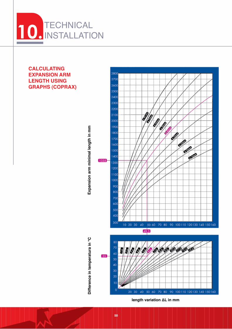
CALCULATING EXPANSION ARM LENGTH USING GRAPHS (COPRAX)
Expa
nsio
n ar
m m
inim
al le
ngth
in m
mD
iffer
ence
in te
mpe
ratu
ra in
°C
length variation ΔL in mm
51
DIAGRAm eXAmPleS
The following are some examples of correct
installation of the COPRAX system on the outside of
walls, with the various techniques adopted to allow
for thermal expansion of the material.
52
Fixed point at base of vertical pipe section Fixed point in the middle of the vertical section
Length absorption with compensation loop in a straight section of pipe
10.TECHNICAL INSTALLATION

11. PRECAUTIONS
53
Use of a system of plastic pipes and fittings offers
a series of advantages from various points of view,
as fully described in „COPRAX system properties”,
Chapter 2 (page 6).
However, in order to enjoy all the benefits of these
properties, the user must be well aware of every
aspect relating to the product. To assist the COPRAX
system user, we have prepared a number of important
recommendations, set out below.
WORKInG COnDITIOnS
The use of COPRAX and COPRAX Fibra in the stated
working conditions creates absolutely no problems
for the material.
However, exceeding the limit conditions for use may
impair the product’s resistance.
All precautions must therefore be taken to ensure
that this does not occur; this not only protects the
system itself, but frequently also its user.
ulTRAVIOleT RAYS
COPRAX must never be installed or stored where it
is subject to direct ultraviolet rays (sunlight or neon
lights). Ultraviolet ray causes ageing in the material,
leading to loss of its initial chemical-physical
characteristics.
HAnDlInG PIPeS
During handling, storage and use on site, bundles
of pipes or individual lengths must be protected
against excessive external stresses, such as shaking,
knocks, hammer blows, etc. This becomes even more
important when ambient temperature falls, since at
low temperatures the material is more rigid and has
a less elastic response to outside stresses.
FORmATIOn OF ICe
When water passes from the liquid to the solid state
(ice), its volume increases to an extent which may
generate stresses inside the installation which the
material is unable to withstand. The appropriate
measures should be taken to ensure that this does not
occur, draining the system completely after testing if
there is the risk of freezing.
COnTACT WITH SHARP eDGeD BODIeS
Any contact with sharp edged bodies (such as brick
shards) causes cuts on the outside of the pipe which
might lead to breakages later. Care should be taken
to ensure that this does not occur during storage and
installation, and any scratched or scored pipes must
not be used
BenDInG
To bend COPRAX system pipes, proceed as follows:
• for very wide radius curves, the pipe may be bent
cold
• for radius close to, but not below, 8 times the
diameter of the pipe concerned, the pipe should
be heated with hot air.
• flames must not be used.
Rmin ≥ 8 D
54
11.PRECAUTIONS
55
FITTInGS WITH meTAl InSeRT
When using COPRAX system fittings with threaded
female metal insert, do not apply excessive
tightening torques when connecting to male
fittings. Also, take care not to place too much hemp
between the parts to be assembled. Teflon is to be
preferred in all cases. In addition, check that the
male part is long enough for a proper connection;
generally, at least one turn of thread should be left
free.
If installation requirements mean that a COPRAX
system fitting must be connected to an iron pipe
or union, the connection should be made using
COPRAX fittings with male thread.
CuTTInG PIPeS
Use tools capable of making a burr-free cut,
perpendicular to the pipe’s axis.
WelDInG
The parts for welding must always be kept thoroughly
clean and the welding machine’s thermostat
must indicate that it has reached the operating
temperature. No twisting or rotation forces must
be applied to the connected parts, either during
or after welding. See page 23, “WelDInG BY A
FuSIOn WelDInG mACHIne”.
56
Testing an installation (according the ENV12108:2001
standard) is essential for its successful operation,
as it allows making sure that the installation does
not have any leakage points for any reasons.
The operations to complete are as follows:
- Visual inspection of the pipes and joints:
this allows checking if the pipes and fittings have
been installed correctly and if there are parts
which have been accidentally damaged by sharp
objects.
- Hydraulic test for checking water-tightness:
it must be carried out when the installation can
still be accessed directly, by filling it with water at
room temperature.
1. When the installation has been filled with
water closed, make it reach testing pressure and
keep it under such pressure for 30 minutes (if
pressure decreases due to the piping settling in,
restore testing pressure at intervals of 10 minutes).
2. Read the pressure value after 30 minutes
using devices with 0.1 bar accuracy. Read the value
of the pressure after another 30 minutes: if the
variation is less than 0.6 bar, the installation has no
leaks. Continue the test for another 2 hours.
3. Read the pressure value after 2 hours, if
pressure has decreased by more than 0.2, bar the
system leaks; otherwise the result of testing is
positive.
For single segments of the installation the
operations referred to in point 3 can be omitted.
TeSTInG PReSSuRe = mAXImum WORKInG
PReSSuRe x 1.5
An appropriate use of the COPRAX System along with
careful testing will avoid any problem even in the
segments of the installations used for transporting
hot water.
N.B. Once the testing is complete, the testing
pressure is discharged from the installation;
sometimes the installation should be completely
discharged of pression, especially if testing has
taken place in a zone subjected to reaching
temperatures around or below 0°C.
This warning aims at avoiding possible unexpected
breakages which may occur due to the formation
of ice on the installations which are supposedly
already tested and therefore are believed to be
free from any inconvenience.
12.TESTING
57
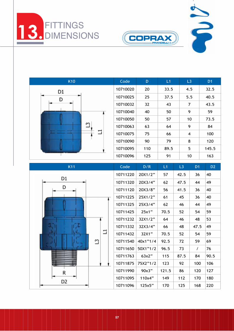
13.FITTINGSDIMENSIONS
K10 Code D L1 L3 D1
10710020 20 33.5 4.5 32.5
10710025 25 37.5 5.5 40.5
10710032 32 43 7 43.5
10710040 40 50 9 59
10710050 50 57 10 73.5
10710063 63 64 9 84
10710075 75 66 4 100
10710090 90 79 8 120
10710095 110 89.5 5 145.5
10710096 125 91 10 163
K11 Code D/R L1 L3 D1 D2
10711220 20X1/2” 57 42.5 36 40
10711320 20X3/4” 62 47.5 44 49
10711120 20X3/8” 56 41.5 36 40
10711225 25X1/2” 61 45 36 40
10711325 25X3/4” 62 46 44 49
10711425 25x1” 70.5 52 54 59
10711232 32X1/2” 64 46 48 53
10711332 32X3/4” 66 48 47.5 49
10711432 32X1” 70.5 52 54 59
10711540 40x1”1/4 92.5 72 59 69
10711650 50X1”1/2 96.5 73 / 76
10711763 63x2” 115 87.5 84 90.5
10711875 75X2”1/2 123 92 100 106
10711990 90x3” 121.5 86 120 127
10711095 110x4” 149 112 170 180
10711096 125x5” 170 125 168 220
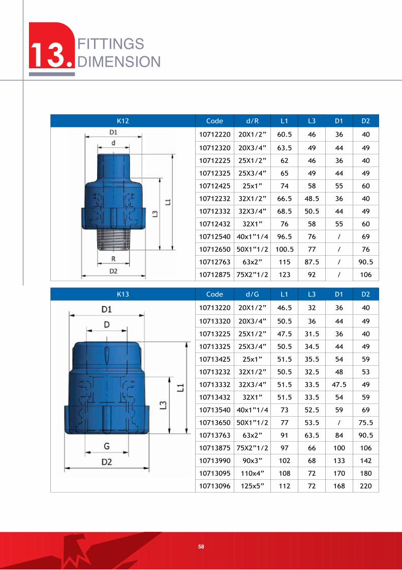
58
FITTINGSDIMENSION
K12 Code d/R L1 L3 D1 D2
10712220 20X1/2” 60.5 46 36 40
10712320 20X3/4” 63.5 49 44 49
10712225 25X1/2” 62 46 36 40
10712325 25X3/4” 65 49 44 49
10712425 25x1” 74 58 55 60
10712232 32X1/2” 66.5 48.5 36 40
10712332 32X3/4” 68.5 50.5 44 49
10712432 32X1” 76 58 55 60
10712540 40x1”1/4 96.5 76 / 69
10712650 50X1”1/2 100.5 77 / 76
10712763 63x2” 115 87.5 / 90.5
10712875 75X2”1/2 123 92 / 106
K13 Code d/G L1 L3 D1 D2
10713220 20X1/2” 46.5 32 36 40
10713320 20X3/4” 50.5 36 44 49
10713225 25X1/2” 47.5 31.5 36 40
10713325 25X3/4” 50.5 34.5 44 49
10713425 25x1” 51.5 35.5 54 59
10713232 32X1/2” 50.5 32.5 48 53
10713332 32X3/4” 51.5 33.5 47.5 49
10713432 32X1” 51.5 33.5 54 59
10713540 40x1”1/4 73 52.5 59 69
10713650 50X1”1/2 77 53.5 / 75.5
10713763 63x2” 91 63.5 84 90.5
10713875 75X2”1/2 97 66 100 106
10713990 90x3” 102 68 133 142
10713095 110x4” 108 72 170 180
10713096 125x5” 112 72 168 220
13.
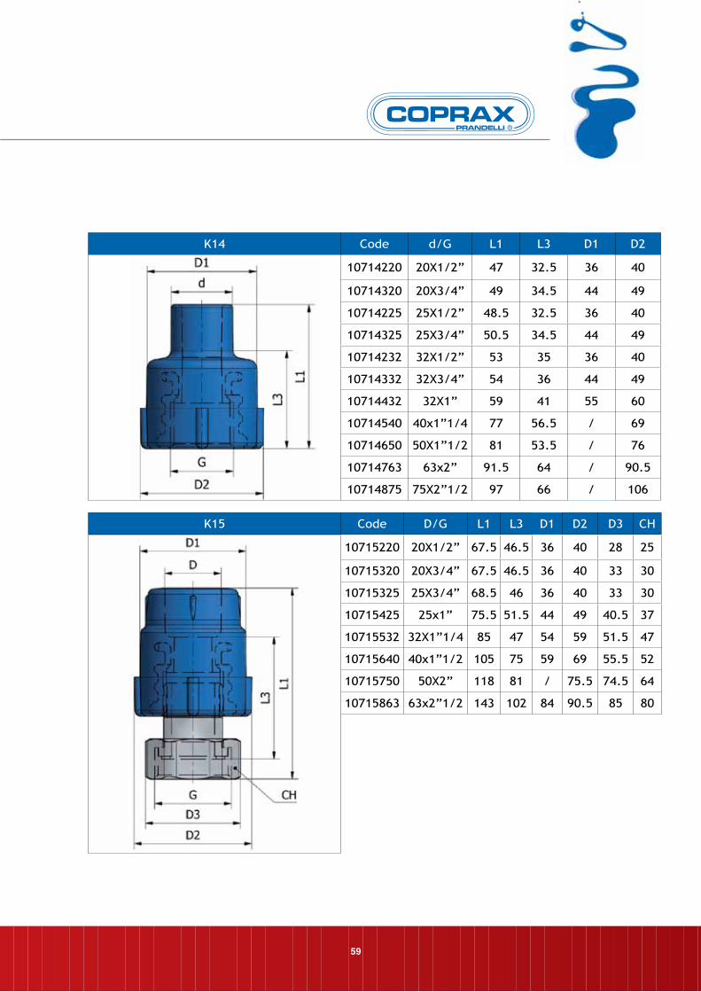
59
K14 Code d/G L1 L3 D1 D2
10714220 20X1/2” 47 32.5 36 40
10714320 20X3/4” 49 34.5 44 49
10714225 25X1/2” 48.5 32.5 36 40
10714325 25X3/4” 50.5 34.5 44 49
10714232 32X1/2” 53 35 36 40
10714332 32X3/4” 54 36 44 49
10714432 32X1” 59 41 55 60
10714540 40x1”1/4 77 56.5 / 69
10714650 50X1”1/2 81 53.5 / 76
10714763 63x2” 91.5 64 / 90.5
10714875 75X2”1/2 97 66 / 106
K15 Code D/G L1 L3 D1 D2 D3 CH
10715220 20X1/2” 67.5 46.5 36 40 28 25
10715320 20X3/4” 67.5 46.5 36 40 33 30
10715325 25X3/4” 68.5 46 36 40 33 30
10715425 25x1” 75.5 51.5 44 49 40.5 37
10715532 32X1”1/4 85 47 54 59 51.5 47
10715640 40x1”1/2 105 75 59 69 55.5 52
10715750 50X2” 118 81 / 75.5 74.5 64
10715863 63x2”1/2 143 102 84 90.5 85 80
60
FITTINGSDIMENSION
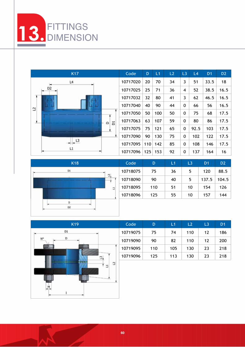
K17 Code D L1 L2 L3 L4 D1 D2
10717020 20 70 34 3 51 33.5 18
10717025 25 71 36 4 52 38.5 16.5
10717032 32 80 41 3 62 46.5 16.5
10717040 40 90 44 0 66 56 16.5
10717050 50 100 50 0 75 68 17.5
10717063 63 107 59 0 80 86 17.5
10717075 75 121 65 0 92.5 103 17.5
10717090 90 130 75 0 102 122 17.5
10717095 110 142 85 0 108 146 17.5
10717096 125 153 92 0 137 164 16
K18 Code D L1 L3 D1 D2
10718075 75 36 5 120 88.5
10718090 90 40 5 137.5 104.5
10718095 110 51 10 154 126
10718096 125 55 10 157 144
K19 Code D L1 L2 L3 D1
10719075 75 74 110 12 186
10719090 90 82 110 12 200
10719095 110 105 130 23 218
10719096 125 113 130 23 218
13.
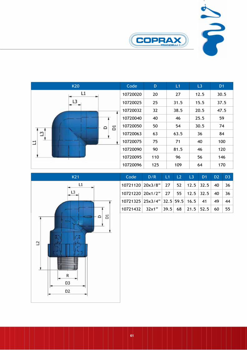
K21 Code D/R L1 L2 L3 D1 D2 D3
10721120 20x3/8” 27 52 12.5 32.5 40 36
10721220 20x1/2” 27 55 12.5 32.5 40 36
10721325 25x3/4” 32.5 59.5 16.5 41 49 44
10721432 32x1” 39.5 68 21.5 52.5 60 55
61
K20 Code D L1 L3 D1
10720020 20 27 12.5 30.5
10720025 25 31.5 15.5 37.5
10720032 32 38.5 20.5 47.5
10720040 40 46 25.5 59
10720050 50 54 30.5 74
10720063 63 63.5 36 84
10720075 75 71 40 100
10720090 90 81.5 46 120
10720095 110 96 56 146
10720096 125 109 64 170
62
FITTINGSDIMENSION
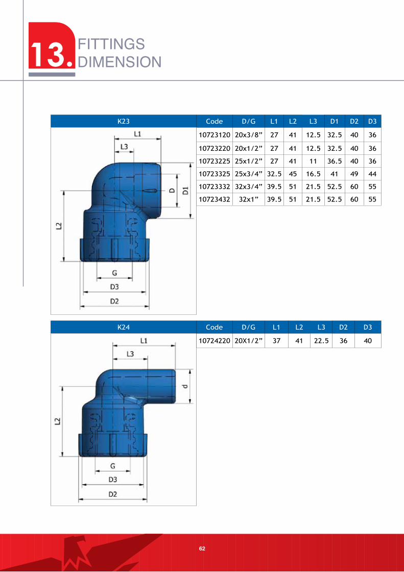
K24 Code D/G L1 L2 L3 D2 D3
10724220 20X1/2” 37 41 22.5 36 40
K23 Code D/G L1 L2 L3 D1 D2 D3
10723120 20x3/8” 27 41 12.5 32.5 40 36
10723220 20x1/2” 27 41 12.5 32.5 40 36
10723225 25x1/2” 27 41 11 36.5 40 36
10723325 25x3/4” 32.5 45 16.5 41 49 44
10723332 32x3/4” 39.5 51 21.5 52.5 60 55
10723432 32x1” 39.5 51 21.5 52.5 60 55
13.
63
K26 Code D/d L1 L2 L3 L4 D1
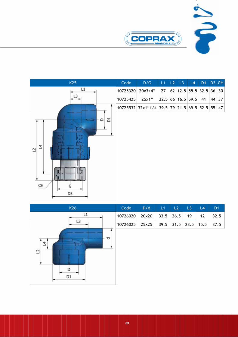
10726020 20x20 33.5 26.5 19 12 32.5
10726025 25x25 39.5 31.5 23.5 15.5 37.5
K25 Code D/G L1 L2 L3 L4 D1 D3 CH
10725320 20x3/4” 27 62 12.5 55.5 32.5 36 30
10725425 25x1” 32.5 66 16.5 59.5 41 44 37
10725532 32x1”1/4 39.5 79 21.5 69.5 52.5 55 47
64
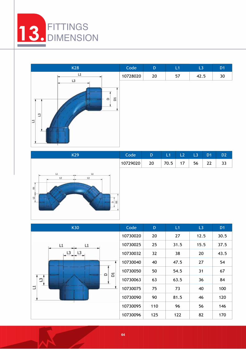
FITTINGSDIMENSION
K29 Code D L1 L2 L3 D1 D2
10729020 20 70.5 17 56 22 33
K28 Code D L1 L3 D1
10728020 20 57 42.5 30
K30 Code D L1 L3 D1
10730020 20 27 12.5 30.5
10730025 25 31.5 15.5 37.5
10730032 32 38 20 43.5
10730040 40 47.5 27 54
10730050 50 54.5 31 67
10730063 63 63.5 36 84
10730075 75 73 40 100
10730090 90 81.5 46 120
10730095 110 96 56 146
10730096 125 122 82 170
13.
65
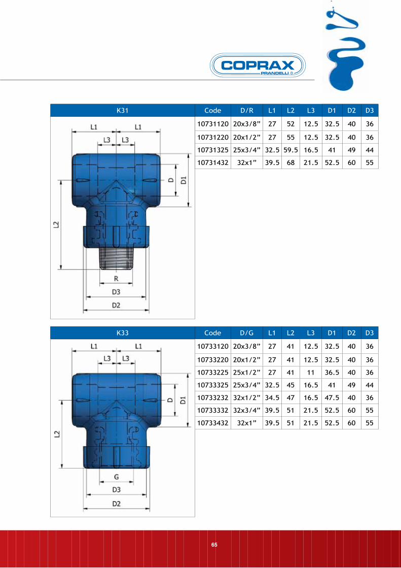
K31 Code D/R L1 L2 L3 D1 D2 D3
10731120 20x3/8” 27 52 12.5 32.5 40 36
10731220 20x1/2” 27 55 12.5 32.5 40 36
10731325 25x3/4” 32.5 59.5 16.5 41 49 44
10731432 32x1” 39.5 68 21.5 52.5 60 55
K33 Code D/G L1 L2 L3 D1 D2 D3
10733120 20x3/8” 27 41 12.5 32.5 40 36
10733220 20x1/2” 27 41 12.5 32.5 40 36
10733225 25x1/2” 27 41 11 36.5 40 36
10733325 25x3/4” 32.5 45 16.5 41 49 44
10733232 32x1/2” 34.5 47 16.5 47.5 40 36
10733332 32x3/4” 39.5 51 21.5 52.5 60 55
10733432 32x1” 39.5 51 21.5 52.5 60 55
66
FITTINGSDIMENSION
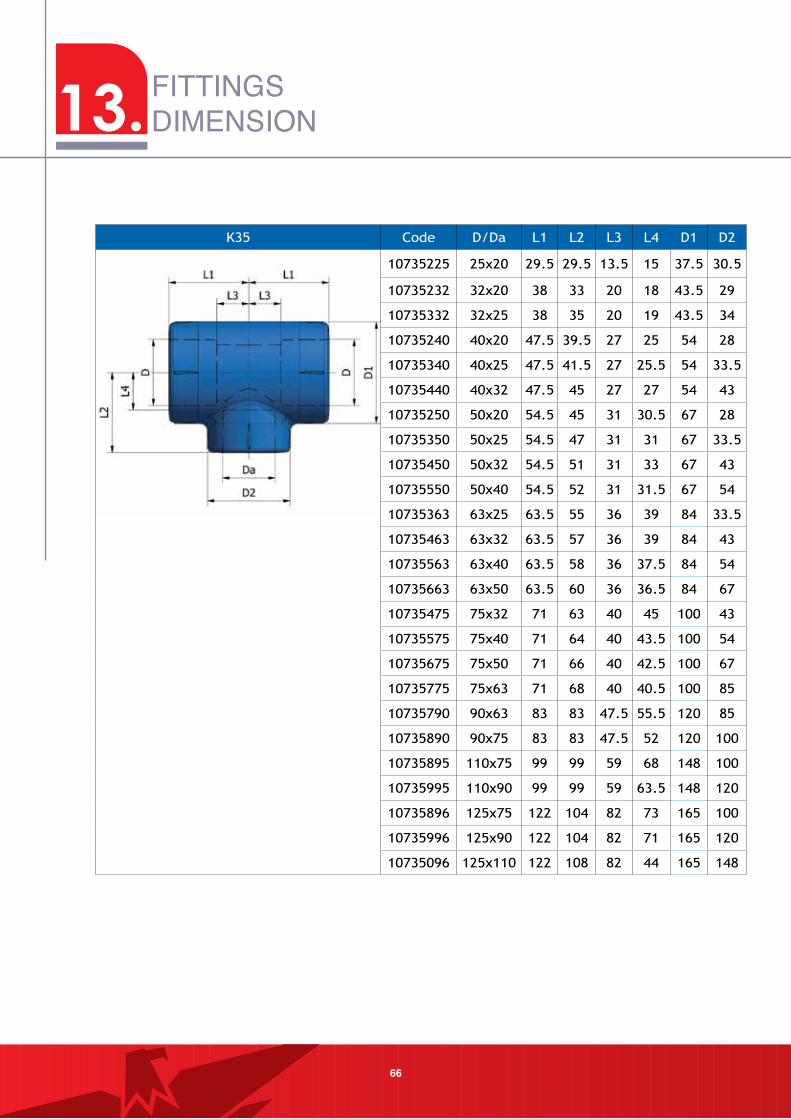
K35 Code D/Da L1 L2 L3 L4 D1 D2
10735225 25x20 29.5 29.5 13.5 15 37.5 30.5
10735232 32x20 38 33 20 18 43.5 29
10735332 32x25 38 35 20 19 43.5 34
10735240 40x20 47.5 39.5 27 25 54 28
10735340 40x25 47.5 41.5 27 25.5 54 33.5
10735440 40x32 47.5 45 27 27 54 43
10735250 50x20 54.5 45 31 30.5 67 28
10735350 50x25 54.5 47 31 31 67 33.5
10735450 50x32 54.5 51 31 33 67 43
10735550 50x40 54.5 52 31 31.5 67 54
10735363 63x25 63.5 55 36 39 84 33.5
10735463 63x32 63.5 57 36 39 84 43
10735563 63x40 63.5 58 36 37.5 84 54
10735663 63x50 63.5 60 36 36.5 84 67
10735475 75x32 71 63 40 45 100 43
10735575 75x40 71 64 40 43.5 100 54
10735675 75x50 71 66 40 42.5 100 67
10735775 75x63 71 68 40 40.5 100 85
10735790 90x63 83 83 47.5 55.5 120 85
10735890 90x75 83 83 47.5 52 120 100
10735895 110x75 99 99 59 68 148 100
10735995 110x90 99 99 59 63.5 148 120
10735896 125x75 122 104 82 73 165 100
10735996 125x90 122 104 82 71 165 120
10735096 125x110 122 108 82 44 165 148
13.
67
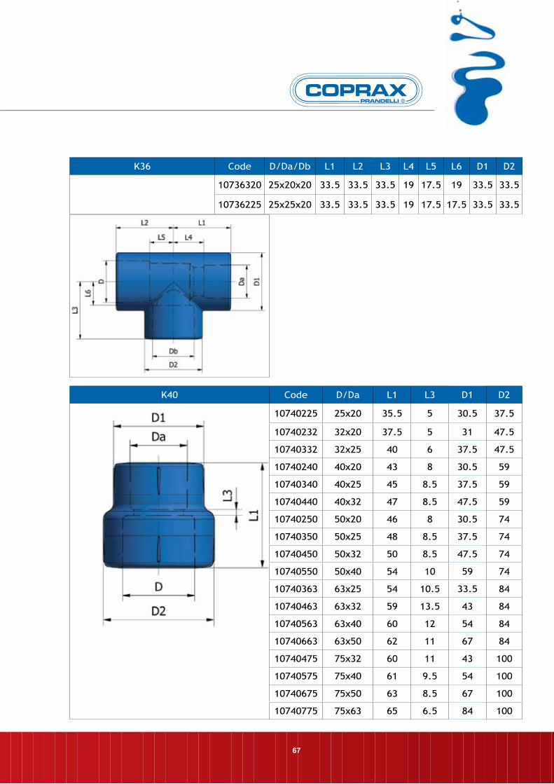
K40 Code D/Da L1 L3 D1 D2
10740225 25x20 35.5 5 30.5 37.5
10740232 32x20 37.5 5 31 47.5
10740332 32x25 40 6 37.5 47.5
10740240 40x20 43 8 30.5 59
10740340 40x25 45 8.5 37.5 59
10740440 40x32 47 8.5 47.5 59
10740250 50x20 46 8 30.5 74
10740350 50x25 48 8.5 37.5 74
10740450 50x32 50 8.5 47.5 74
10740550 50x40 54 10 59 74
10740363 63x25 54 10.5 33.5 84
10740463 63x32 59 13.5 43 84
10740563 63x40 60 12 54 84
10740663 63x50 62 11 67 84
10740475 75x32 60 11 43 100
10740575 75x40 61 9.5 54 100
10740675 75x50 63 8.5 67 100
10740775 75x63 65 6.5 84 100
K36 Code D/Da/Db L1 L2 L3 L4 L5 L6 D1 D2
10736320 25x20x20 33.5 33.5 33.5 19 17.5 19 33.5 33.5
10736225 25x25x20 33.5 33.5 33.5 19 17.5 17.5 33.5 33.5
68
FITTINGSDIMENSION
K41 Code d/D L1 L3 D1
10741320 25x20 37.5 7 30.5
10741420 32x20 35.5 3 32
10741425 32x25 39.5 5.5 38.5
10741963 90x63 86.5 23.5 84
10741975 90x75 94.5 28 100
10741063 110x63 85 24 110
10741075 110x75 89 27 110
10741090 110x90 92 17 119
K47 Code D/Tu d L1 L3 D1 D2
10747620 20/50 20 32.5 6 30.5 36.5
10747720 20/63 20 33.5 6 30.5 36.5
10747820 20/75 20 35 6 30.5 36.5
10747920 20/90 20 37 6 30.5 36.5
10747625 25/50 25 37.5 7.5 37.5 43.5
10747725 25/63 25 38 7.5 37.5 43.5
10747825 25/75 25 39.5 7.5 37.5 43.5
10747925 25/90 25 41 7.5 37.5 43.5
10747732 32/63 32 49.5 13.5 47.5 54
10747832 32/75 32 49.8 13.5 47.5 54
10747932 32/90 32 51 13.5 47.5 54
10747132 32/110 32 53.5 13.5 47.5 54
10747940 40/90 40 54 11 59 66
10747140 40/110 40 55.5 11 59 66
13.
69
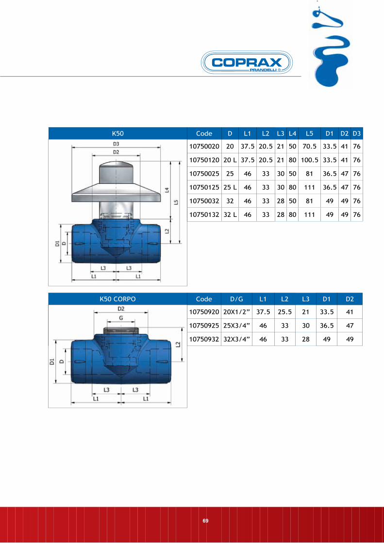
K50 CORPO Code D/G L1 L2 L3 D1 D2
10750920 20X1/2” 37.5 25.5 21 33.5 41
10750925 25X3/4” 46 33 30 36.5 47
10750932 32X3/4” 46 33 28 49 49
K50 Code D L1 L2 L3 L4 L5 D1 D2 D3
10750020 20 37.5 20.5 21 50 70.5 33.5 41 76
10750120 20 L 37.5 20.5 21 80 100.5 33.5 41 76
10750025 25 46 33 30 50 81 36.5 47 76
10750125 25 L 46 33 30 80 111 36.5 47 76
10750032 32 46 33 28 50 81 49 49 76
10750132 32 L 46 33 28 80 111 49 49 76
70
FITTINGSDIMENSION
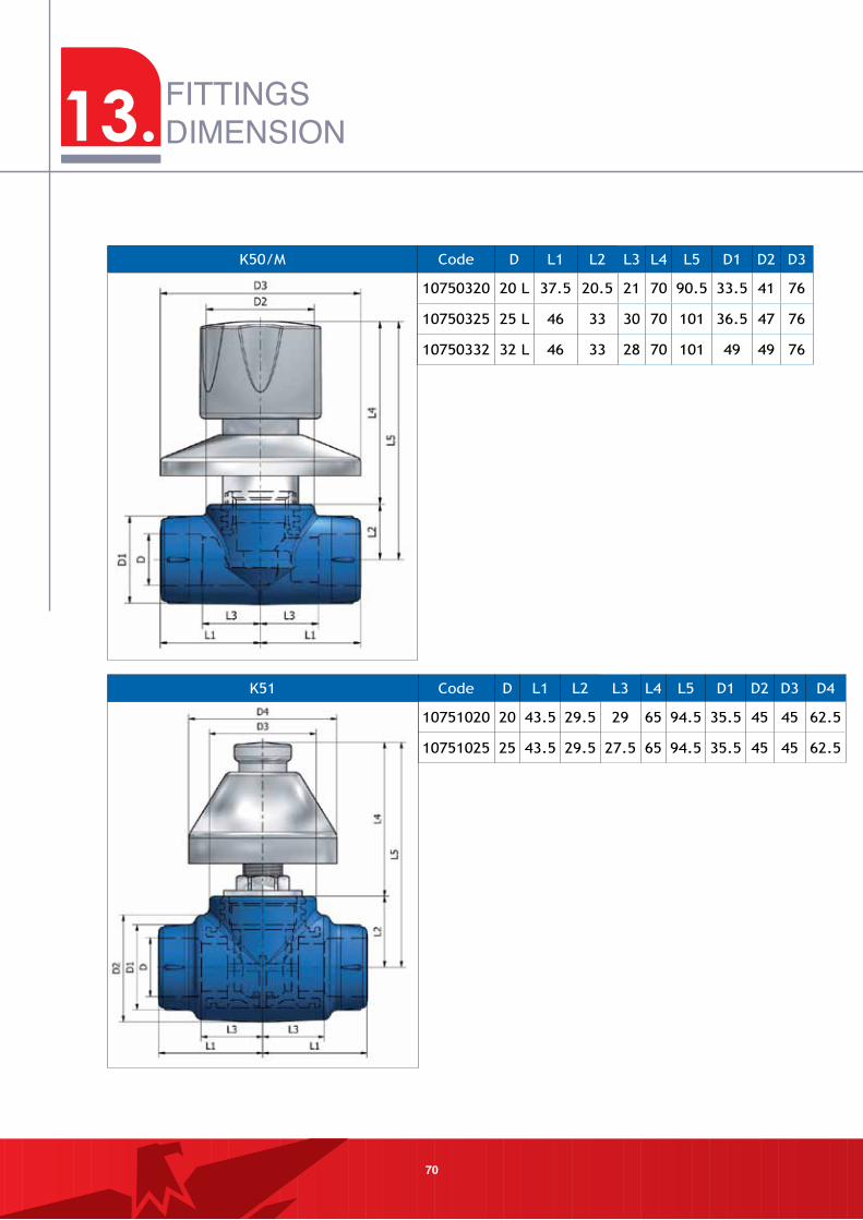
K50/M Code D L1 L2 L3 L4 L5 D1 D2 D3
10750320 20 L 37.5 20.5 21 70 90.5 33.5 41 76
10750325 25 L 46 33 30 70 101 36.5 47 76
10750332 32 L 46 33 28 70 101 49 49 76
K51 Code D L1 L2 L3 L4 L5 D1 D2 D3 D4
10751020 20 43.5 29.5 29 65 94.5 35.5 45 45 62.5
10751025 25 43.5 29.5 27.5 65 94.5 35.5 45 45 62.5
13.
71
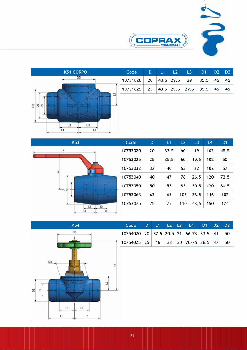
K53 Code D L1 L2 L3 L4 D1
10753020 20 33.5 60 19 102 45.5
10753025 25 35.5 60 19.5 102 50
10753032 32 40 63 22 102 57
10753040 40 47 78 26.5 120 72.5
10753050 50 55 83 30.5 120 84.5
10753063 63 65 103 36.5 146 102
10753075 75 75 110 43,5 150 124
K54 Code D L1 L2 L3 L4 D1 D2 D3
10754020 20 37.5 20.5 21 66-73 33.5 41 50
10754025 25 46 33 30 70-76 36.5 47 50
K51 CORPO Code D L1 L2 L3 D1 D2 D3
10751820 20 43.5 29.5 29 35.5 45 45
10751825 25 43.5 29.5 27.5 35.5 45 45
72
FITTINGSDIMENSION
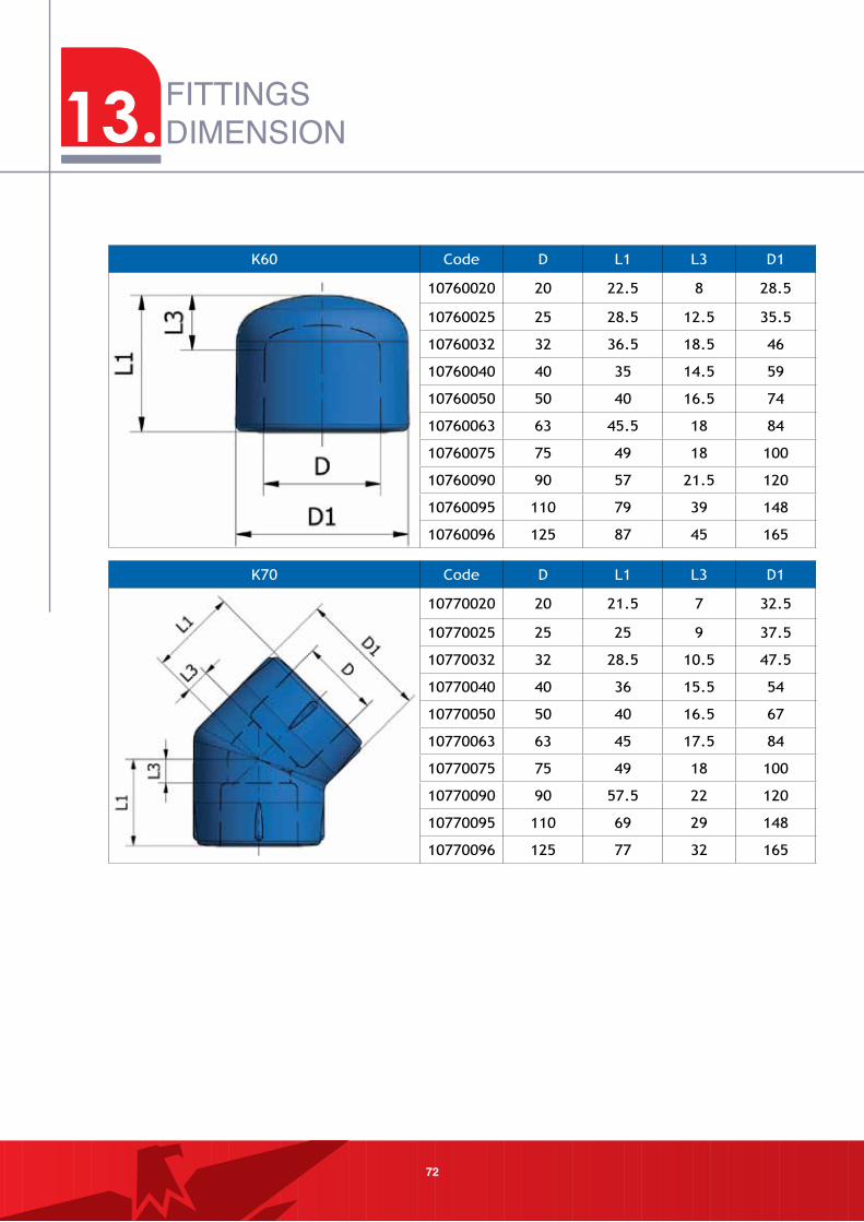
K70 Code D L1 L3 D1
10770020 20 21.5 7 32.5
10770025 25 25 9 37.5
10770032 32 28.5 10.5 47.5
10770040 40 36 15.5 54
10770050 50 40 16.5 67
10770063 63 45 17.5 84
10770075 75 49 18 100
10770090 90 57.5 22 120
10770095 110 69 29 148
10770096 125 77 32 165
K60 Code D L1 L3 D1
10760020 20 22.5 8 28.5
10760025 25 28.5 12.5 35.5
10760032 32 36.5 18.5 46
10760040 40 35 14.5 59
10760050 50 40 16.5 74
10760063 63 45.5 18 84
10760075 75 49 18 100
10760090 90 57 21.5 120
10760095 110 79 39 148
10760096 125 87 45 165
13.
73
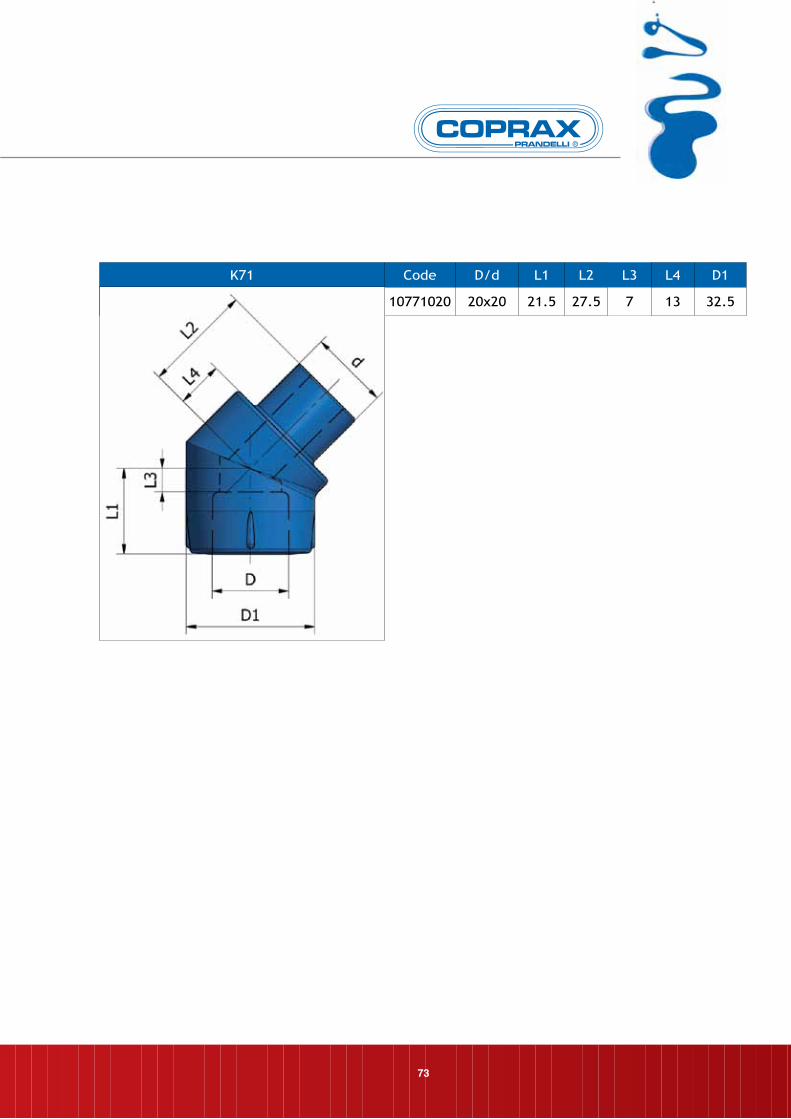
K71 Code D/d L1 L2 L3 L4 D1
10771020 20x20 21.5 27.5 7 13 32.5
74
FITTINGSDIMENSION
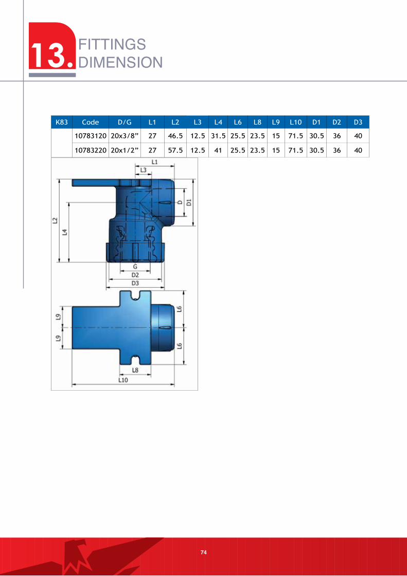
K83 Code D/G L1 L2 L3 L4 L6 L8 L9 L10 D1 D2 D3
10783120 20x3/8” 27 46.5 12.5 31.5 25.5 23.5 15 71.5 30.5 36 40
10783220 20x1/2” 27 57.5 12.5 41 25.5 23.5 15 71.5 30.5 36 40
13.
75
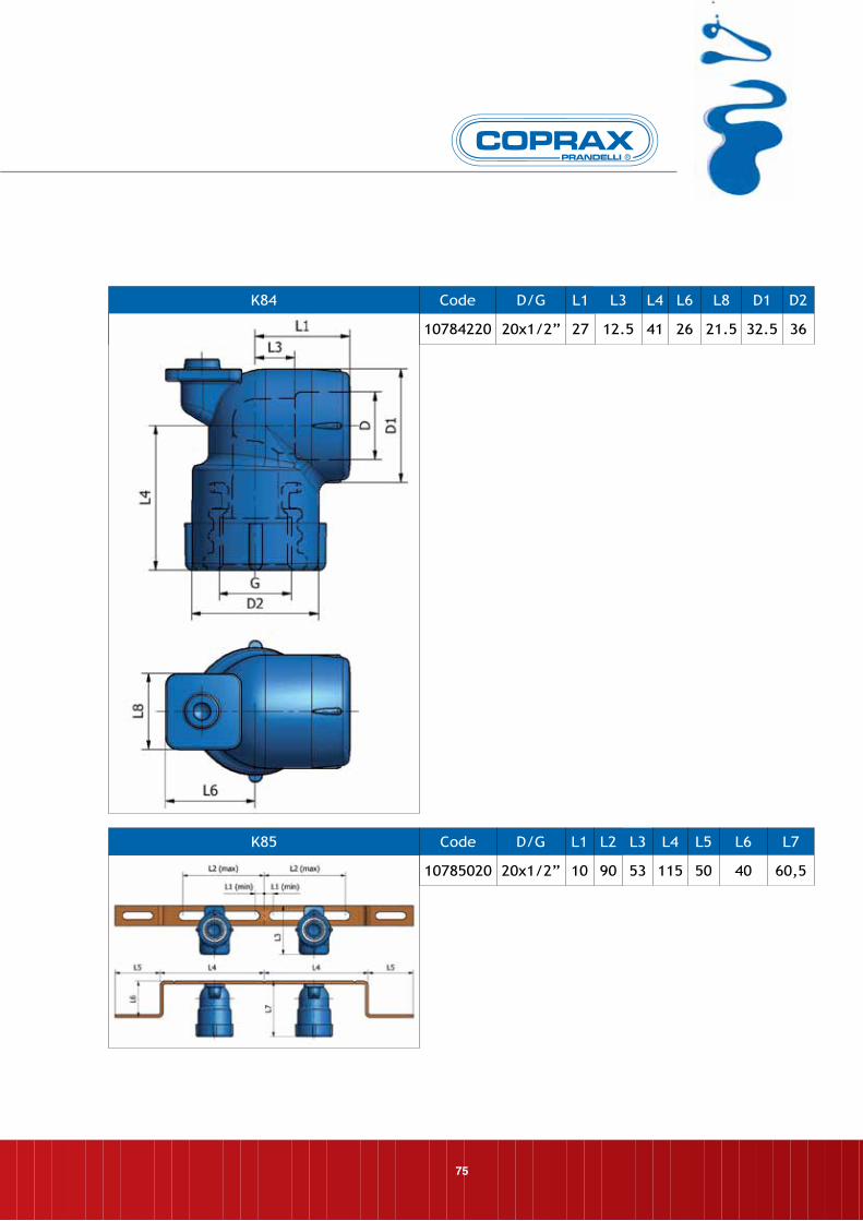
K84 Code D/G L1 L3 L4 L6 L8 D1 D2
10784220 20x1/2” 27 12.5 41 26 21.5 32.5 36
K85 Code D/G L1 L2 L3 L4 L5 L6 L7
10785020 20x1/2” 10 90 53 115 50 40 60,5
76
FITTINGSDIMENSION
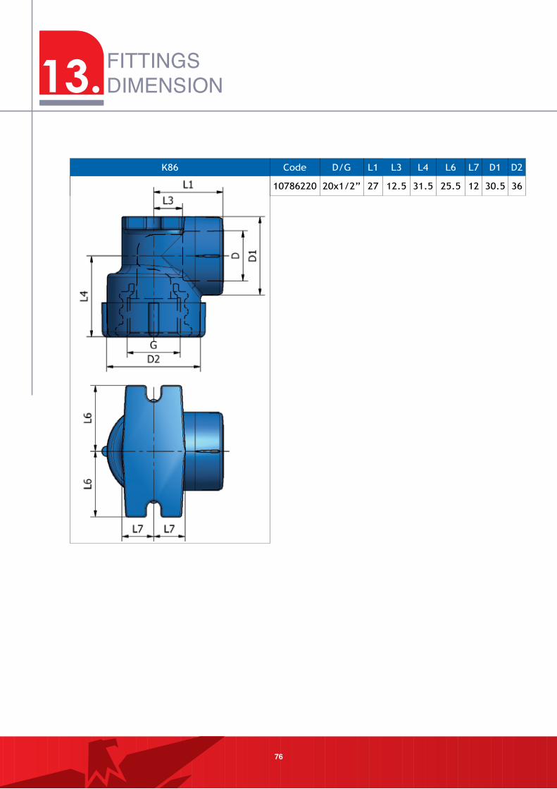
K86 Code D/G L1 L3 L4 L6 L7 D1 D2
10786220 20x1/2” 27 12.5 31.5 25.5 12 30.5 36
13.
77
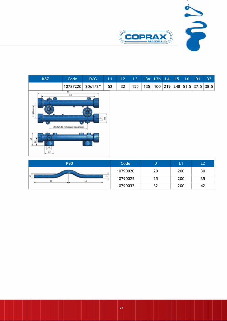
K90 Code D L1 L2
10790020 20 200 30
10790025 25 200 35
10790032 32 200 42
K87 Code D/G L1 L2 L3 L3a L3b L4 L5 L6 D1 D2
10787220 20x1/2” 52 32 155 135 100 219 248 51.5 37.5 38.5
78
FITTINGSDIMENSION
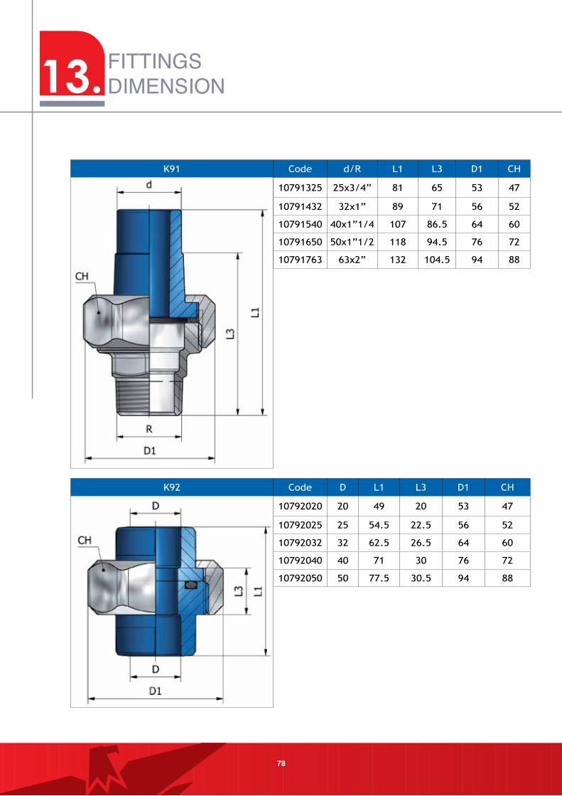
K92 Code D L1 L3 D1 CH
10792020 20 49 20 53 47
10792025 25 54.5 22.5 56 52
10792032 32 62.5 26.5 64 60
10792040 40 71 30 76 72
10792050 50 77.5 30.5 94 88
K91 Code d/R L1 L3 D1 CH
10791325 25x3/4” 81 65 53 47
10791432 32x1” 89 71 56 52
10791540 40x1”1/4 107 86.5 64 60
10791650 50x1”1/2 118 94.5 76 72
10791763 63x2” 132 104.5 94 88
13.
79
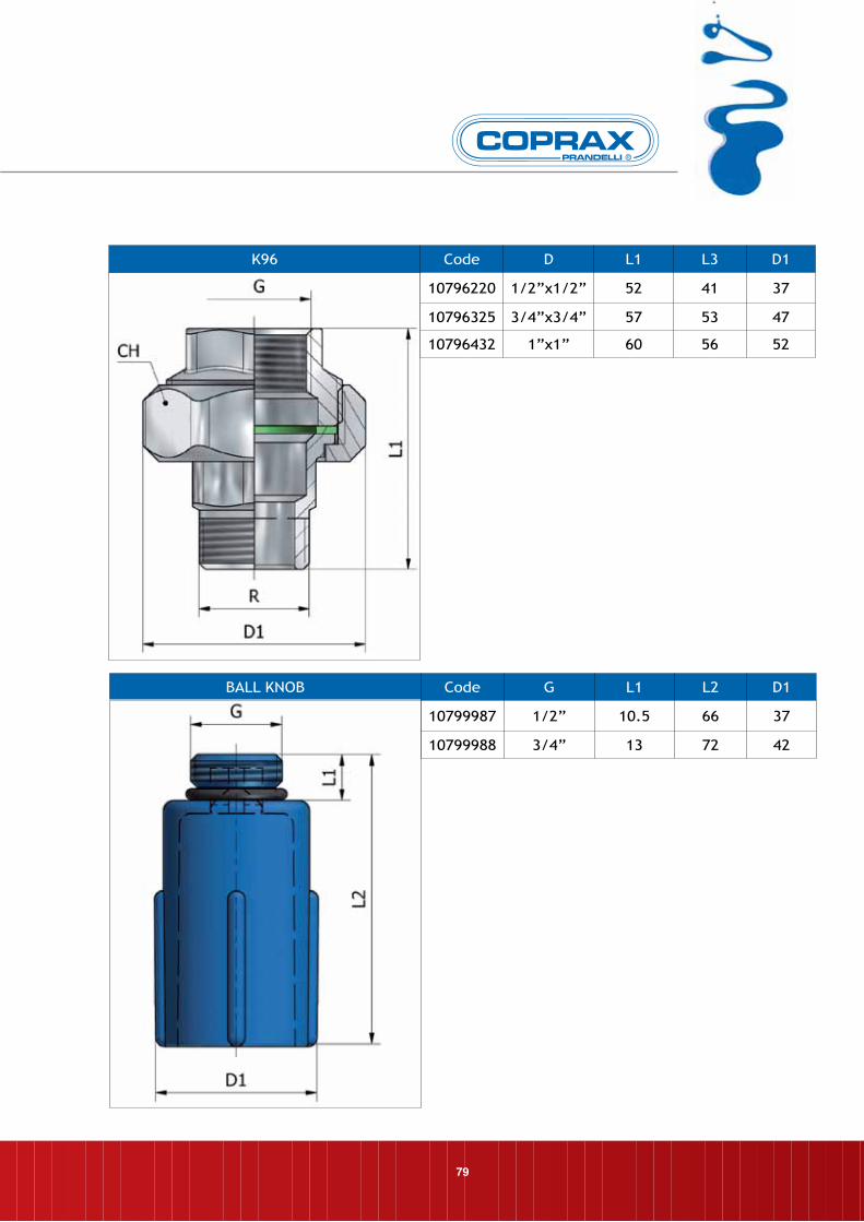
K96 Code D L1 L3 D1
10796220 1/2”x1/2” 52 41 37
10796325 3/4”x3/4” 57 53 47
10796432 1”x1” 60 56 52
BALL KNOB Code G L1 L2 D1
10799987 1/2” 10.5 66 37
10799988 3/4” 13 72 42

80
NOTES


Prandelli S.p.A. Via Rango, 58 lumezzAne (BS) Italy
Tel. +39 030 892 0922 Fax. +39 030 892 1739
www.prandelli.com e-mail: [email protected]


