JohnsonDiversey
CIP Cleaning in place
• The circulation of non foaming cleaners without dismantling
the equipment.
• An automatic and systematic cleaning of the inner
surfaces of tanks, heat exchangers, pumps, valves
and pipes.
JohnsonDiversey
CIP properties
• Strong and hot solutions can be used. The heat, the chemistry and the mechanics can be sustained long.
• The solutions can be reused.
• Can be automated and reproducibility is good.
• Investment in equipment is high.
• The mechanics are not always sufficient
JohnsonDiversey
JohnsonDiversey
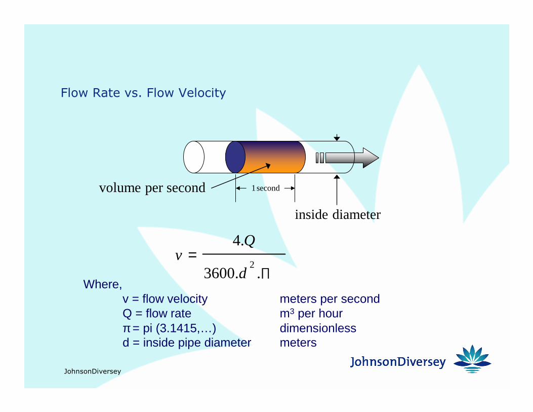
Flow Rate vs. Flow Velocity
∏=
..3600
.4
2d
Qv
Where,v = flow velocity meters per secondQ = flow rate m3 per hourπ = pi (3.1415,…) dimensionlessd = inside pipe diameter meters
second 1secondper volume
diameter inside
JohnsonDiversey
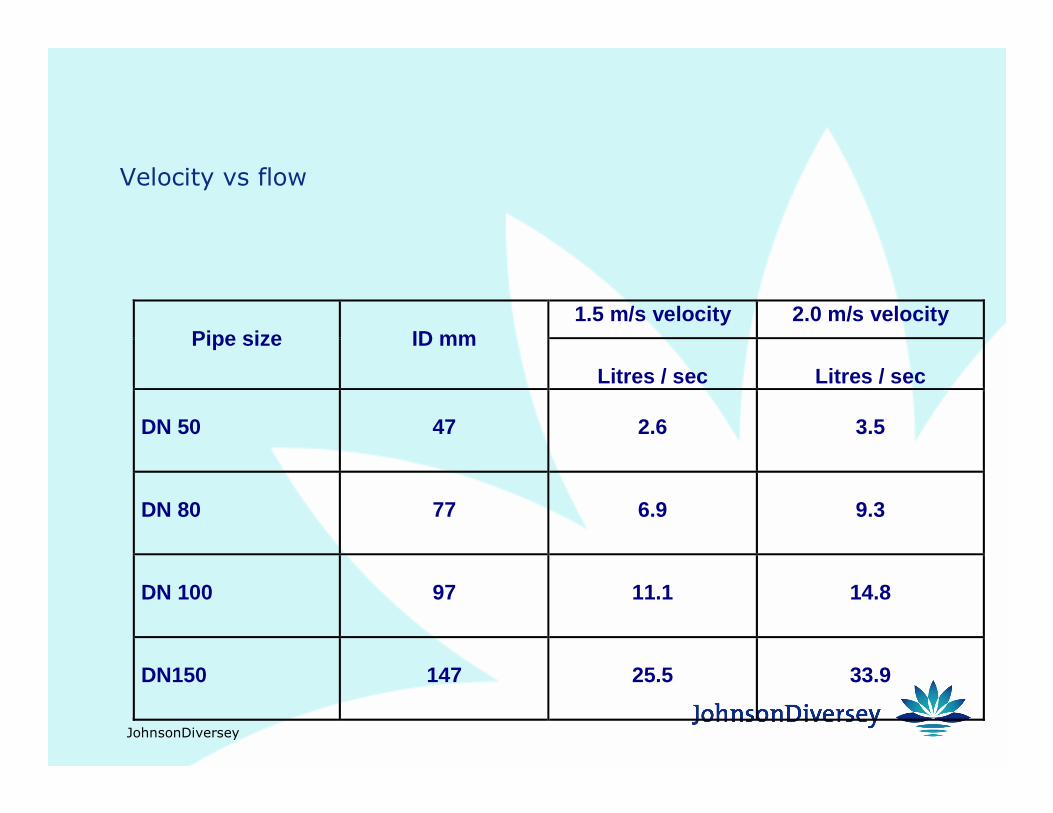
Velocity vs flow
1.5 m/s velocity 2.0 m/s velocityPipe size ID mm
Litres / sec Litres / sec
DN 50 47 2.6 3.5
DN 80 77 6.9 9.3
DN 100 97 11.1 14.8
DN150 147 25.5 33.9
JohnsonDiversey
Vertical vessel flow requirements - sprayballs
� Vertical vessels
� For most vessels, the sprayball delivers a uniform
quantity of solution to the upper circumference of the
vessel
� Based on soil level, deliver a given quantity of solution
to a unit length of circumference - called liquid loading:
� Don’t forget about flow OUT of vessels

JohnsonDiversey
Sprayball Placement
Θ⋅+=2
-180tan D Height Dome Sprayball ofDepth
Where,θ = angle of coverage, degreesD = diameter of vessel, metersDome height meters
NOTE: This is valid for simplevessels without obstructions.Additional sprayballs may berequired.
Depth of Sprayball
Dome WeldSprayball
Dome Height
140º
JohnsonDiversey
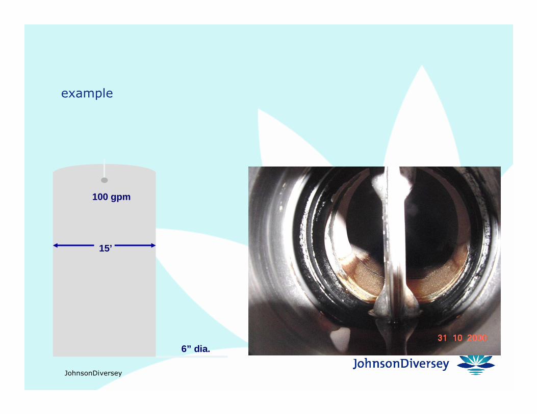
example
15’
100 gpm
6” dia.
JohnsonDiversey
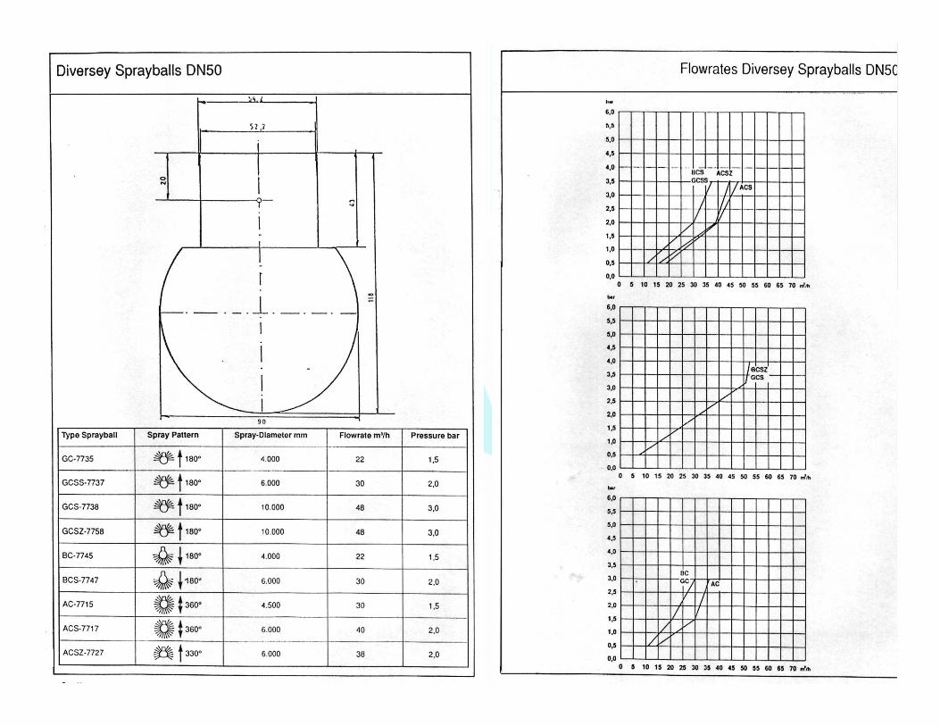
Sprayball pressure
� Sprayball pressure is critical
� Generally in the range (1.0) 1.5 - 2.5 (3.0) bar
� Too little pressure and the vessel walls are not reached
� Too much and the spray atomises reducing mechanical
action
� Larger sprayballs with larger hole diameters can operate
at higher pressures without atomising.
� All sprayballs have specified flow / pressure curves
JohnsonDiversey
JohnsonDiversey
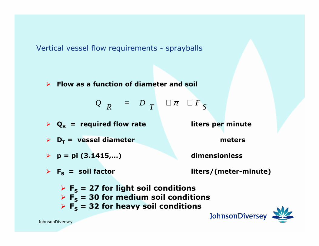
Vertical vessel flow requirements - sprayballs
� Flow as a function of diameter and soil
� QR = required flow rate liters per minute
� DT = vessel diameter meters
� p = pi (3.1415,…) dimensionless
� FS = soil factor liters/(meter-minute)
� FS = 27 for light soil conditions
� FS = 30 for medium soil conditions
� FS = 32 for heavy soil conditions
SFTDRQ ⋅⋅= π
JohnsonDiversey

JohnsonDiversey
JohnsonDiversey
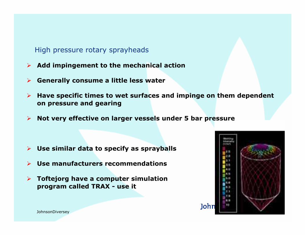
High pressure rotary sprayheads
� Add impingement to the mechanical action
� Generally consume a little less water
� Have specific times to wet surfaces and impinge on them dependent
on pressure and gearing
� Not very effective on larger vessels under 5 bar pressure
� Use similar data to specify as sprayballs
� Use manufacturers recommendations
� Toftejorg have a computer simulation
program called TRAX - use it
JohnsonDiversey
CIP Optimizing
� CIP optimizing is the process of minimizing the cost inputs of CIP
cleaning
� water
� effluent
� energy
�chemical
�electrical
�heat� CO2
� production time

JohnsonDiversey
Optimizing drivers
� CIP system design
� clean circuits - no dead legs, no flow splits
� accurate and non competing instrumentation - conductivity
monitoring
� no leaks
� CIP program
� correct CIP program philosophy
� CIP preparation sequence - correct conductivity starting point
� tidy CIP fluids interface management - always in lines never in
tanks
� correct valve sequencing on monitor signals
� defined terminators each CIP step
JohnsonDiversey
CIP optimizing - circuit volume
� To predict CIP losses and costs we must know the CIP circuit volume.
� This has nothing to do with the size of the CIP tanks.
� It is the amount of liquid held up in the CIP headers and the vessel or line being
cleaned.
� To calculate the circuit volume for a line clean we need to know the diameters of
the lines and the length of each line size.
� To calculate the circuit volume of a vessel clean we need to know the line
information and the dimensions of the vessel being cleaned.
� If there is other processing plant in the CIP circuit, we need to know it’s volume
too.
JohnsonDiversey
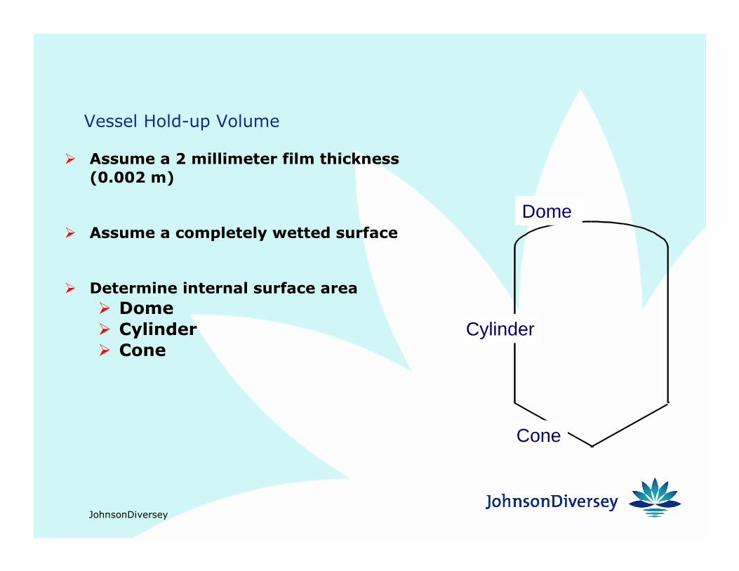
Vessel Hold-up Volume
� Assume a 2 millimeter film thickness
(0.002 m)
� Assume a completely wetted surface
� Determine internal surface area
� Dome
� Cylinder
� Cone
Dome
Cylinder
Cone

JohnsonDiversey
Vessel Hold-up Volume
� Area of Dome:
� Area of Cylinder:
� Area of Coneh2
h1
D
2DomeArea rπ=
2CylinderArea hDπ=
( )2121
2
4ConeArea hDD +=π
Dr2
1:NOTE =
JohnsonDiversey
CIP optimizing - chemical loss management
� Liquid loss for an efficient vessel CIP system is about 10% of circuit volume.
� Line cleans can be run more efficiently than vessel cleans - as low as 5% loss.
� Effective loss management depends on:
� Effective Flow meter or conductivity interface detection.
� Managing liquid interfaces into pipes not vessels.
� When managing liquid changes in vessels the program must be stepped.
� New liquid to sprayball chasing old liquid into vessel.
� Over scavenge old liquid from vessel into return line.
� New liquid into vessel chasing old along return line to interface
detector.
� First step should be volumetric and set for each vessel.
JohnsonDiversey
CIP optimizing - chemical loss management
� measured as % of concentrate detergent lost compared to the concentrate
detergent in the CIP circuit volume
� concentrate detergent lost is calculated by CIP tank, volume and
concentration, before and after CIP
� concentrate detergent in circuit volume calculated as the volume of solution
held in the CIP circuit excluding the CIP tank at the starting concentration
JohnsonDiversey
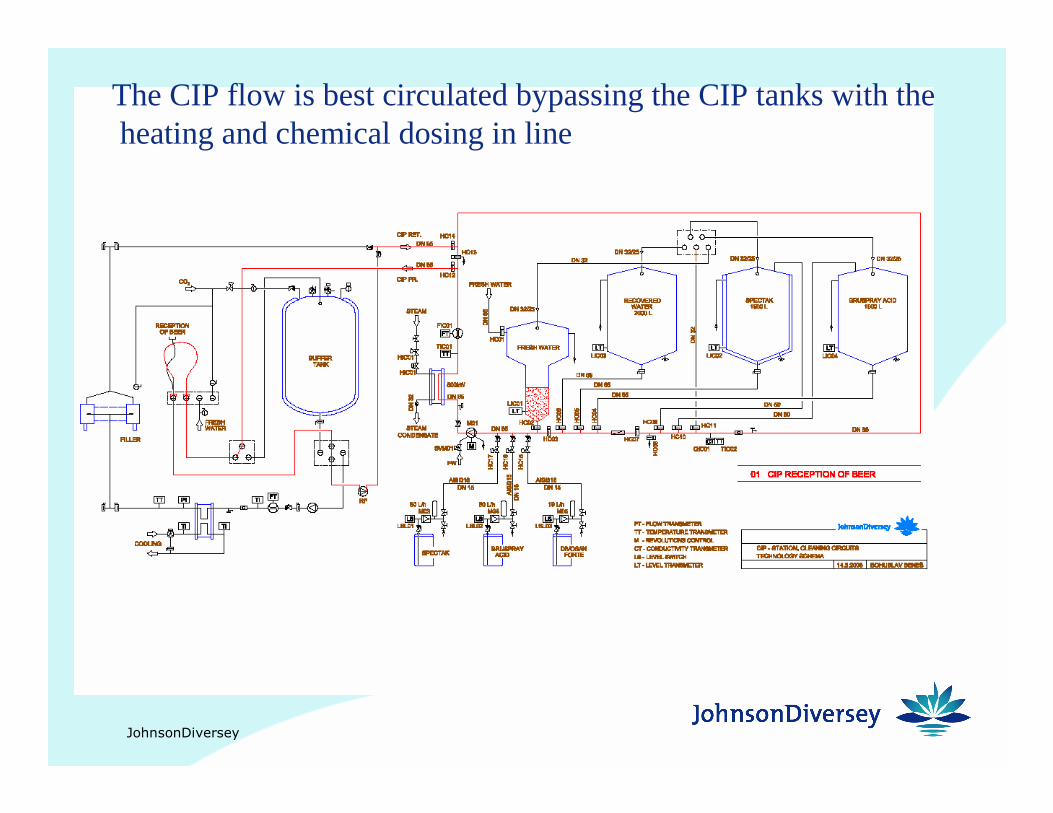
The CIP flow is best circulated bypassing the CIP tankswith theheating and chemical dosing in line


