
MULTI SIZE SHAPE DETECTION
LIM CZE SIANG
This report is submitted in particular fulfilment of the requirements for the award of
Bachelor of Electronic Engineering with Computer Engineering With Honours
Faculty of Electronic and Computer Engineering
Universiti Teknikal Malaysia Melaka
April 2010
ii
UNIVERSTI TEKNIKAL MALAYSIA MELAKA
FAKULTI KEJURUTERAAN ELEKTRONIK DAN KEJURUTERAAN
KOMPUTER
BORANG PENGESAHAN STATUS LAPORAN
PROJEK SARJANA MUDA II
Tajuk Projek : MULTI SIZE SHAPE DETECTION
Sesi
Pengajian : 2009/2010 -2
Saya ………………………LIM CZE SIANG……………………………..
(HURUF BESAR)
mengaku membenarkan Laporan Projek Sarjana Muda ini disimpan di Perpustakaan dengan
syarat-syarat kegunaan seperti berikut:
1. Laporan adalah hakmilik Universiti Teknikal Malaysia Melaka.
2. Perpustakaan dibenarkan membuat salinan untuk tujuan pengajian sahaja.
3. Perpustakaan dibenarkan membuat salinan laporan ini sebagai bahan pertukaran antara
institusi pengajian tinggi.
4. Sila tandakan ( √ ) :
SULIT*
(Mengandungi maklumat yang berdarjah keselamatan
atau kepentingan Malaysia seperti yang termaktub di
dalam AKTA RAHSIA RASMI 1972)
TERHAD*
(Mengandungi maklumat terhad yang telah ditentukan
oleh organisasi/badan di mana penyelidikan dijalankan)
TIDAK TERHAD
Disahkan oleh:
__________________________ ___________________________________
(TANDATANGAN PENULIS) (COP DAN TANDATANGAN PENYELIA)
Alamat Tetap:319,TAMAN TUAN
SHEIKH,71000 PORT DICKSON,N.SEMBILAN
Tarikh:30 APRIL 2010 j Tarikh:30 APRIL 2010
Tarikh: ……………………….. Tarikh: ………………………..

iii
“I hereby declare that this report is result of my own effort except for works that have
been cited clearly in the references.”
Signature : ……………………………….
Name : LIM CZE SIANG
Date : 30 APRIL 2010

iv
“I hereby declare that I have read this report and in my opinion this report is
sufficient in terms of the scope and quality for the award of Bachelor of Electronic
Engineering (Computer Engineering) With Honours”
SIGNATURE : ……………………………….
NAME : MR KHAIRUL AZHA B. A. AZIZ
DATE : 30 APRIL 2010

v
Specially dedicated to my family for their supports and eternal love.

vi
ACKNOWLEDGEMENTS
Praise to God, the Most Gracious and Most Merciful, Who has created the
mankind with knowledge, wisdom and power.
First of all, the author would like to express his deepest gratitude to Encik Mr
Khairul Azha B. A. Aziz for his continuous support, ideas, supervision and
encouragement during the course of this project. The author would not have
completed this project successfully without his assistance.
I am also indebted to Universiti Teknikal Malaysia Melaka (UTeM) for their
encouragement and financial support during my study. Not forgetting to all my
fellow postgraduate students and friends for their moral support and help me during
the entire degree programme. Without their continued support and interest, this
project would not have been realized. Appreciation is also acknowledged to those
who have contributed directly or indirectly in the completion of this project.
The author would also like to extend his appreciation to his family members,
for their support, patience and endless love.
vii
ABSTRACT
Shape is the characteristic surface configuration of a thing such as an outline
or contour. It can also be described give a particular form to create. The objective of
this project is to design a system that can detect same shape even though in various
size. The input of the system will be an image which can be any type of files
containing many shapes with example circle, square, rectangular and others with
multiple sizes. This project is mainly concern with shape classification using image
processing technique. The proposed methods can be extended to various purpose
especially in speeding up the processing time to search the shapes in the image. The
system will be developed using MATLAB. For example in industrial, wafer dicing is
the process by which die are separated from a wafer of semiconductor following the
processing of the wafer. The die created may be any shape generated by straight lines,
but they are typically rectangular or square shaped. The program developed may be
used to check the accuracy of the die been created.
viii
ABSTRAK
Bentuk merupakan satu ciri dimana permukaan konfigurasi benda seperti
garis atau kontur. Ia boleh dijelaskan seperti objek yang dihasilkan. Tujuan projek ini
adalah menghasilkan satu sistem dengan kebolehan menemui bentuk yang sama
tetapi dalam saiz yang berbeza. Input kepada sistem tersebut adalah dengan imej
yang dalam bentuk format yang berbeza yang mengandungi bulatan, segi empat sama,
segi empat dan lain-lain dalam saiz yang berbeza. Projek ini mengambil berat
tentang klasfikasi bentuk dengan menggunakan teknik pemprosesan imej. Cara yang
dicadangkan boleh digunakan dalam pelbagai sebagai mencepatkan masa
pemprosesan dalam penemuan bentuk dalam image. Sistem tersebut akan dihasilkan
dengan menggunakan MATLAB. Sebagai contoh dalam industri, pendaduan wafer
merupakan proses dimana dadu diasingkan daripada wafer dalam industri
semikonduktor dimana pemprosesing wafer dilakukan. Dadu boleh dihasilkan
melalui penghasilan bentuk dengan garis lurus dengan bentuk segiempat dan segi
empat sama bentuk. Program yang dihasilkan dapat digunakan untuk meyemak
ketepatan dadu yang dihasilkan.
ix
TABLE OF CONTENTS
CHAPTER CONTENT PAGE
DECLARATION ii
DEDICATION v
ACKNOWLEDGEMENTS vi
ABSTRACT vii
ABSTRAK viii
LIST OF CONTENTS ix
LIST OF TABLES xii
LIST OF FIGURES xiii
LIST OF NOTATIONS xvi
LIST OF EQUATIONS xvii
LIST OF ABREVIATIONS xviii
LIST OF APPENDICES xix
I. INTRODUCTION
1.1 Introduction to shape analysis
and recognition 1
1.2 Objective 6
1.3 Scope of the work 6
1.4 Problem Statement 7
1.5 Outline Thesis 9
II. LITERATURE REVIEW
2.1 Introduction 10
2.2 Research of various methods 11
x
2.3 Practically used 14
2.4 Shape Characterization 15
2.4.1 Perimeter 15
2.4.2 Area 17
2.4.3 Centroid 18
2.5 Basic of Image Processing 19
2.6 Matlab For Image Processing 22
III. METHODOLOGY
3.1 Introduction 25
3.2 Overall System 25
3.3 Development Process 26
3.3.1 Flow Chart of Project 26
3.3.2 Flow Chart of Programming
-Sliding Window 28
3.3.3 Flow Chart of Programming
-Centroid 29
3.4 Commands 30
3.4.1 Image Acquisition 30
3.4.2 Image Storing 34
IV. RESULT AND DISCUSSION
4.1 Introduction 35
4.2 Testing on the images 35
4.2.1 Simulation using image 35
created by software Paint
4.2.2 Simulation using image 40
created by software Paint
with unwanted noise
xi
4.2.3 Simulation using image 43
taken using digital camera
without filter
4.2.4 Results using image taken 48
by digital camera with filtering
4.2.5 Simulation using image taken 52
by digital camera with better
direction with filtering
4.2.6 Simulation using image taken 57
by digital camera with constant
background
4.2.7 Simulation using image with 60
sliding window method
4.3 Analysis Overall Result
4.3.1 Processing time 63
4.4 Discussion 63
V. CONCLUSION
5.1 Summary 64
5.2 Conclusion 64
5.3 Recommendation for future project 65
5.4 Commercialization or Industrial Potential 65
REFERENCES 66
APPENDICES 67
xii
LIST OF TABLES
NO TITLE PAGE
Table 1.1 Shape analysis applications 4
Table 2.1 Task List for Shape 10
Table 2.2 Pixel value conventions 14
Table 2.3 Perimeter of Shapes 15
Table 2.4 Area of Shapes 17
xiii
LIST OF FIGURES
NO TITLE PAGE
Figure 1.1 Typical shape analysis tasks and their organization into
three main classes 2
Figure 1.2 Shape detection involves locating the objects of
interest in the image 7
Figure 1.3 Shape detection involves locating the objects of interest
in the real image. 8
Figure 1.4 Shape detection involves locating the objects of interest
in the real image taken from digital camera. 8
Figure 2.1 Block diagram of a decision theoretic pattern classifier 11
Figure 2.2 Radial Basis Function Networks 13
Figure 2.3 Hidden Units 13
Figure 2.4: The boundary concept 14
Figure 2.5 Centroid of a shape 18
Figure 2.6: Shape matching finding the correct corresponding points
between a given shape A and a target shape B. 19
Figure 2.7 Noise present in the image. 20
Figure 2.8 Sliding Window Movement 21
Figure 3.1 Flow Chart of Project 27
Figure 3.2 Flow Chart of Sliding Window Method 28
Figure 3.3 Flow Chart of Centroid Method 29
Figure 3.4 To read the image in command 30
Figure 3.5 To convert RGB image into grayscale image command 31
Figure 3.6 To threshold the gray image into binary, Crop function is
call and the binary image is display command. 31
xiv
NO TITLE PAGE
Figure 3.7 To invert the binary image command. 32
Figure 3.8 To fill the selected image background command 32
Figure 3.9 To trace the region boundaries in binary image 33
Figure 3.10 Calling Function cropper 33
Figure 3.11 Display the image been cropped 33
Figure 4.1 Original Image 36
Figure 4.2 Grayscale Image 36
Figure 4.3 Binary Image 37
Figure 4.4 Inverted Binary Image 37
Figure 4.5 Filling the background Image 38
Figure 4.6 Trace region boundaries in binary image. 38
Figure 4.7 Result of the image. 39
Figure 4.8 Original Image 40
Figure 4.9 Grayscale Image 40
Figure 4.10 Binary Image 41
Figure 4.11 Inverted Binary Image 41
Figure 4.12 Filling the background Image 42
Figure 4.13 Trace region boundaries in binary image. 42
Figure 4.14 Result of the image. 43
Figure 4.15 Original Image 44
Figure 4.16 Grayscale Image 44
Figure 4.17 Binary Image 45
Figure 4.18 Inverted Binary Image 45
Figure 4.19 Filling the background Image. 46
Figure 4.20 Trace region boundaries in binary image. 46
Figure 4.21 Result of the image. 47
Figure 4.22 Cropped Image 47
Figure 4.23 Original Image 48
Figure 4.24 Grayscale Image 48
Figure 4.25 Binary Image 49
Figure 4.26 Inverted Binary Image 49
xv
NO TITLE PAGE
Figure 4.27 Filling the background Image. 50
Figure 4.28 Trace region boundaries in binary image. 50
Figure 4.29 Result of the image. 51
Figure 4.30 Cropped Image 51
Figure 4.31 Original Image 52
Figure 4.32 Grayscale Image 52
Figure 4.33 Binary Image 53
Figure 4.34 Inverted Binary Image 53
Figure 4.35 Filling the background Image. 54
Figure 4.36 Trace region boundaries in binary image. 54
Figure 4.37 Result of the image. 55
Figure 4.38 Cropped Image 56
Figure 4.39 Original Image and Grayscale Image 57
Figure 4.40 Inverted Binary Image and Inverted Binary Image 57
Figure 4.41 Filling the background Image Trace region boundaries
in binary image 58
Figure 4.42 Result of the image. 58
Figure 4.43 Cropped image. 59
Figure 4.44 Original Image 60
Figure 4.45 Grayscale Image 60
Figure 4.46 Binary Image 61
Figure 4.47 Inverted Binary Image 61
Figure 4.48 Tracing using Sliding Window 62
Figure 4.49 Image Detected 62

xvi
LIST OF NOTATIONS
Miscellaneous
ϕ RBF activation functions 13

xvii
LIST OF EQUATIONS
Table 2.3:Perimeter of Shapes 15
Table 2.4:Area of Shapes 17
Figure 2.5:Centroid of a shape 18
xviii
LIST OF ABREVIATIONS
RBF - Radial Basis Function
JPEG - Joint Photographic Experts Group
GIF - Graphics Interchange Format
Bitmap - Microsoft Windows Bitmap
TIFF - Tagged Image File Format.
PNG - Portable Network Graphic

xix
LIST OF APPENDIX
APPENDIX A-SOURCE CODE 67
CHAPTER I
INTRODUCTION
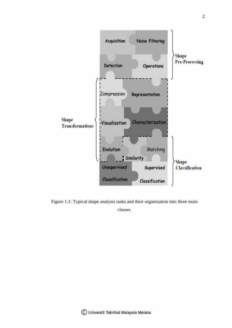
1.1 INTRODUCTION TO SHAPE ANALYSIS AND RECOGNITION
Shape analysis and recognition using computers always encounter many
problems. In fact, the computational shape analysis involves several important tasks
from image acquisition to shape classification. Shape processing for shape analysis
which can be categories into 3 stages which are shape pre-processing, shape
transformations and shape classification.
2
Figure 1.1: Typical shape analysis tasks and their organization into three main
classes.
3
Shape Pre-Processing
The first step toward shape analysis of a given object involves acquiring and
storing an image of it and separating the object of interest from other unwanted
image structures. Furthermore, digital images are usually corrupted with noise and
other undesirable effects such as occlusion and distortions. Therefore, it required
special procedures to apply the application shape preprocessing.
Shape Transformations
Once the shape of interest has been acquired and processed. Next, the noise
has been substantially reduced using some function available in MATLAB. A set of
techniques or algorithms can be applied in order to extract information from the
shape, so that it can be proceed to analyze potion. Such information in normally
extracted by applying suitable shape transformations. Such transformations are
mappings that allow both representation of the shape in a more appropriate manner
with respect to a specific task and extraction of measures that are used by
classification schemes.
Shape Classification
Finally, after shape processing, representation and characterization which
often involving feature extraction, classification algorithms are usually applied in
order to assign a class to each considered shape. There are two particularly important
aspects related to shape classification. The first is the problem of is the given an input
shape. Later, deciding whether it belongs to some specific predefined class. This can
also be thought of as a shape recognition problem is known as supervised
classification. The second equally important aspect of shape classification is how to
define or identify the involved classes in a population of previously unclassified
shapes. This represents a difficult task, and expert knowledge acquisition problems
are usually involved. The latter situation is known as unsupervised classification or
clustering. Both supervised and unsupervised classification involve comparing
4
shapes which deciding how similar two shapes and how is done, in many situations,
by matching important corresponding points of them.
Below are the Fields and examples of application which are using image
processing:
Table 1.1: Shape analysis applications
Research Field Examples of Applications
Neuroscience Morphological taxonomy of neural cells, investigations
about the interplay between form and function,
comparisons between cells of different cortical areas and
between cells of different species, modeling of
biologically realistic cells, and simulation of neural
structures
Document Analysis World Wide Web(WWW), Optical Character Recognition
(OCR), multimedia databases, and historical documents
Visual Arts Video restoration, special effects, video tracking, games,
computer graphics, visualizations, and image synthesis
Internet Content-based information retrieval, watermarking,
graphic design and usability,
Medicine Tumor recognition, quantification of change and/or
deformation of anatomical structures (e.g.,endocardial
contour of left ventricle of heart, corpus callosum),
morphometric analysis for diagnosis (e.g., multiple
sclerosis and Alzheimer's disease), numerical analysis of
chromosomes, identification of genetic pathologies,
laparoscopy, genetic studies of dentofacial morphology.
Biology Morphometric-based evolution comparison, taxonomy,
interplay between form and function, comparative
anatomy, cytology, identification and counting of cells
(e.g., white blood cells), characterization of cells and
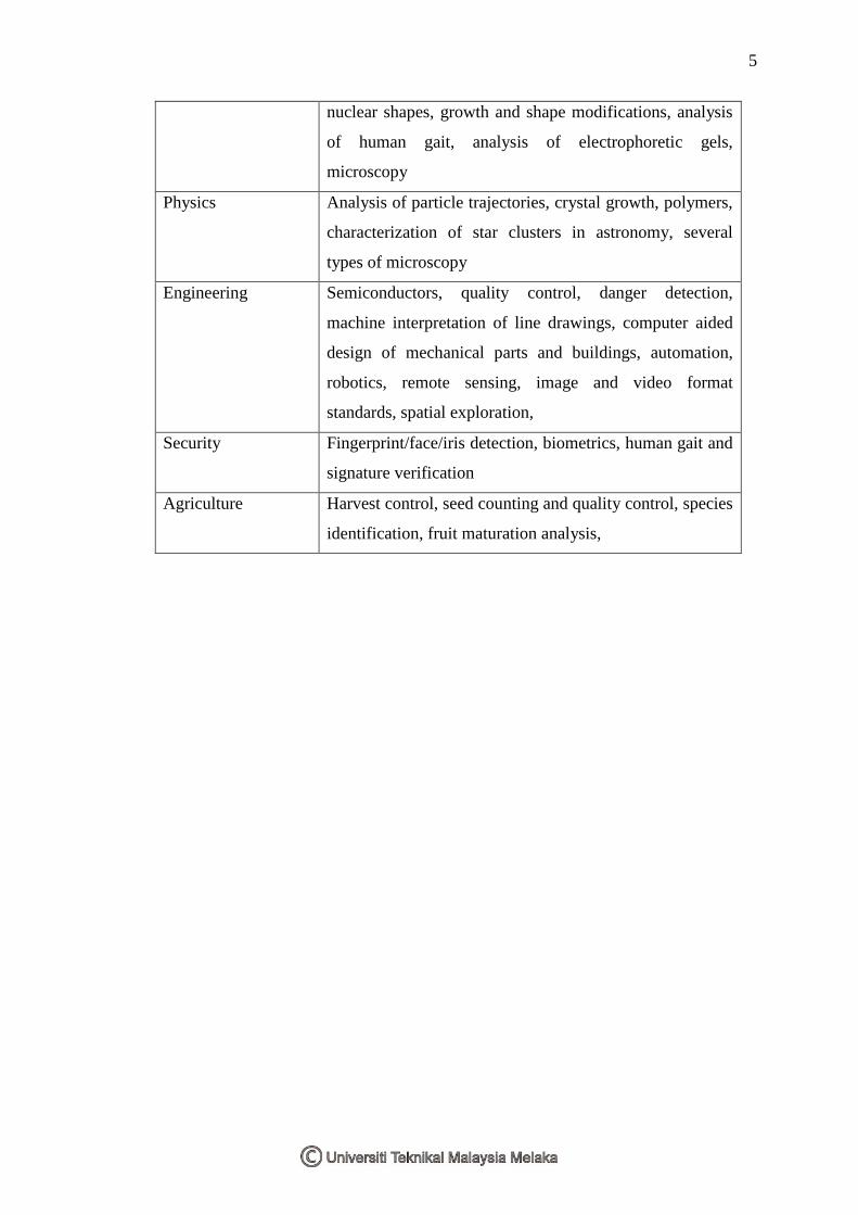
5
nuclear shapes, growth and shape modifications, analysis
of human gait, analysis of electrophoretic gels,
microscopy
Physics Analysis of particle trajectories, crystal growth, polymers,
characterization of star clusters in astronomy, several
types of microscopy
Engineering Semiconductors, quality control, danger detection,
machine interpretation of line drawings, computer aided
design of mechanical parts and buildings, automation,
robotics, remote sensing, image and video format
standards, spatial exploration,
Security Fingerprint/face/iris detection, biometrics, human gait and
signature verification
Agriculture Harvest control, seed counting and quality control, species
identification, fruit maturation analysis,
Field Examples of Applications


