1/03
- 201
6
DF
KOBOLD Instruments, Inc.1801 Parkway View DrivePittsburgh, PA 15205
measuring
•
monitoring
•
analyzing
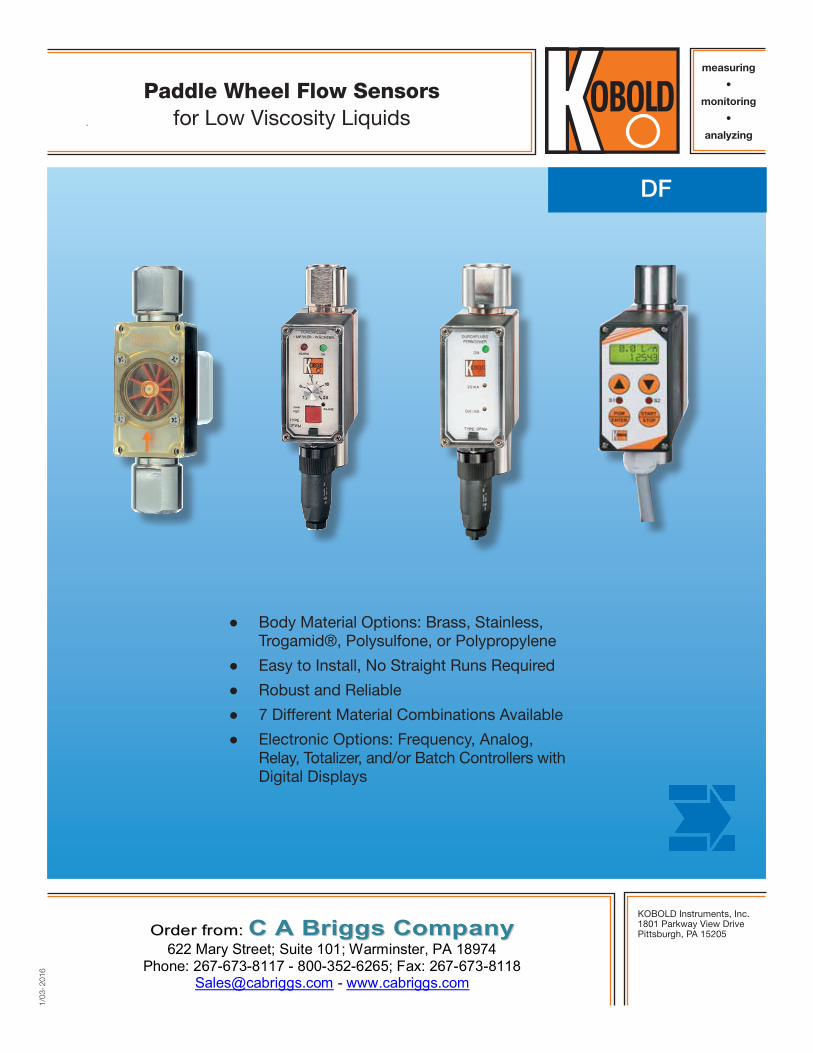
Paddle Wheel Flow Sensorsfor Low Viscosity Liquids
● Body Material Options: Brass, Stainless, Trogamid®, Polysulfone, or Polypropylene
● Easy to Install, No Straight Runs Required
● Robust and Reliable
● 7 Different Material Combinations Available
● Electronic Options: Frequency, Analog, Relay, Totalizer, and/or Batch Controllers with Digital Displays
OOrrddeerr ffrroomm:: CC AA BBrriiggggss CCoommppaannyy 622 Mary Street; Suite 101; Warminster, PA 18974
Phone: 267-673-8117 - 800-352-6265; Fax: 267-673-8118 [email protected] - www.cabriggs.com
2No responsibility taken for errors;
subject to change without prior notice.
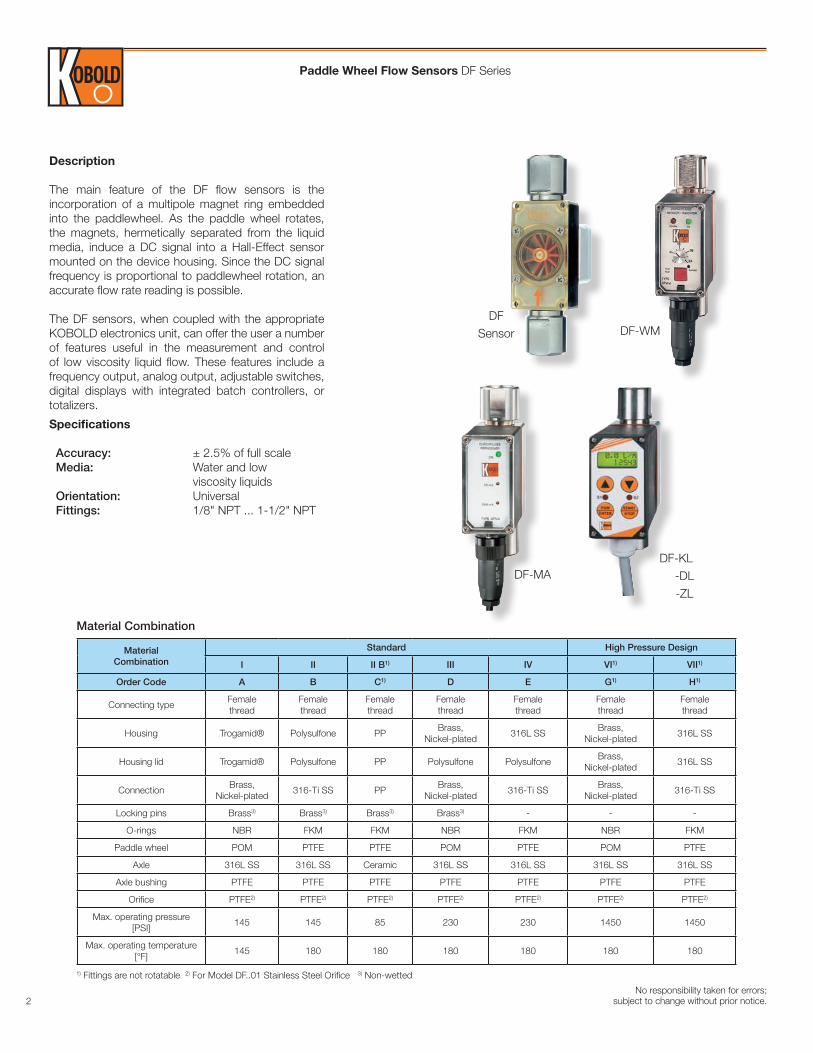
Description
The main feature of the DF flow sensors is the incorporation of a multipole magnet ring embedded into the paddlewheel. As the paddle wheel rotates, the magnets, hermetically separated from the liquid media, induce a DC signal into a Hall-Effect sensor mounted on the device housing. Since the DC signal frequency is proportional to paddlewheel rotation, an accurate flow rate reading is possible.
The DF sensors, when coupled with the appropriate KOBOLD electronics unit, can offer the user a number of features useful in the measurement and control of low viscosity liquid flow. These features include a frequency output, analog output, adjustable switches, digital displays with integrated batch controllers, or totalizers.
Specifications
Accuracy: ± 2.5% of full scale Media: Water and low viscosity liquids Orientation: Universal Fittings: 1/8" NPT ... 1-1/2" NPT
MaterialCombination
Standard High Pressure Design
I II II B1) III IV VI1) VII1)
Order Code A B C1) D E G1) H1)
Connecting typeFemale thread
Female thread
Female thread
Female thread
Female thread
Female thread
Female thread
Housing Trogamid® Polysulfone PPBrass,
Nickel-plated316L SS
Brass, Nickel-plated
316L SS
Housing lid Trogamid® Polysulfone PP Polysulfone PolysulfoneBrass,
Nickel-plated316L SS
ConnectionBrass,
Nickel-plated316-Ti SS PP
Brass, Nickel-plated
316-Ti SSBrass,
Nickel-plated316-Ti SS
Locking pins Brass3) Brass3) Brass3) Brass3) - - -
O-rings NBR FKM FKM NBR FKM NBR FKM
Paddle wheel POM PTFE PTFE POM PTFE POM PTFE
Axle 316L SS 316L SS Ceramic 316L SS 316L SS 316L SS 316L SS
Axle bushing PTFE PTFE PTFE PTFE PTFE PTFE PTFE
Orifice PTFE2) PTFE2) PTFE2) PTFE2) PTFE2) PTFE2) PTFE2)
Max. operating pressure [PSI]
145 145 85 230 230 1450 1450
Max. operating temperature [°F]
145 180 180 180 180 180 180
Material Combination
1) Fittings are not rotatable 2) For Model DF..01 Stainless Steel Orifice 3) Non-wetted
DFSensor
DF-MA
DF-WM
DF-KL -DL -ZL
Paddle Wheel Flow Sensors DF Series
3No responsibility taken for errors; subject to change without prior notice.
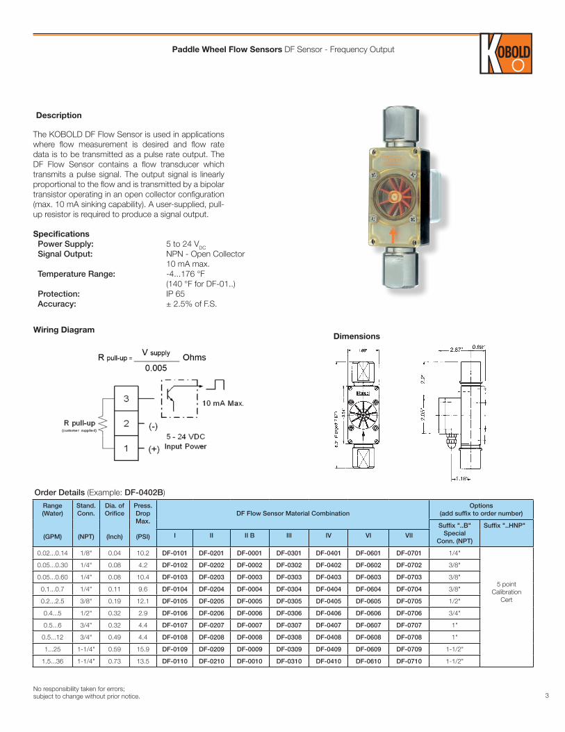
The KOBOLD DF Flow Sensor is used in applications where flow measurement is desired and flow rate data is to be transmitted as a pulse rate output. The DF Flow Sensor contains a flow transducer which transmits a pulse signal. The output signal is linearly proportional to the flow and is transmitted by a bipolar transistor operating in an open collector configuration (max. 10 mA sinking capability). A user-supplied, pull-up resistor is required to produce a signal output.
Specifications Power Supply: 5 to 24 VDC Signal Output: NPN - Open Collector 10 mA max. Temperature Range: -4...176 °F (140 °F for DF-01..) Protection: IP 65 Accuracy: ± 2.5% of F.S.
DimensionsWiring Diagram
Range(Water)
(GPM)
Stand.Conn.
(NPT)
Dia. ofOrifice
(Inch)
Press.Drop Max.
(PSI)
DF Flow Sensor Material CombinationOptions
(add suffix to order number)
Suffix "..B"Special
Conn. (NPT)
Suffix "..HNP"
I II II B III IV VI VII
0.02...0.14 1/8" 0.04 10.2 DF-0101 DF-0201 DF-0001 DF-0301 DF-0401 DF-0601 DF-0701 1/4"
5 point Calibration
Cert
0.05...0.30 1/4" 0.08 4.2 DF-0102 DF-0202 DF-0002 DF-0302 DF-0402 DF-0602 DF-0702 3/8"
0.05...0.60 1/4" 0.08 10.4 DF-0103 DF-0203 DF-0003 DF-0303 DF-0403 DF-0603 DF-0703 3/8"
0.1...0.7 1/4" 0.11 9.6 DF-0104 DF-0204 DF-0004 DF-0304 DF-0404 DF-0604 DF-0704 3/8"
0.2...2.5 3/8" 0.19 12.1 DF-0105 DF-0205 DF-0005 DF-0305 DF-0405 DF-0605 DF-0705 1/2"
0.4...5 1/2" 0.32 2.9 DF-0106 DF-0206 DF-0006 DF-0306 DF-0406 DF-0606 DF-0706 3/4"
0.5...6 3/4" 0.32 4.4 DF-0107 DF-0207 DF-0007 DF-0307 DF-0407 DF-0607 DF-0707 1"
0.5...12 3/4" 0.49 4.4 DF-0108 DF-0208 DF-0008 DF-0308 DF-0408 DF-0608 DF-0708 1"
1...25 1-1/4" 0.59 15.9 DF-0109 DF-0209 DF-0009 DF-0309 DF-0409 DF-0609 DF-0709 1-1/2"
1.5...36 1-1/4" 0.73 13.5 DF-0110 DF-0210 DF-0010 DF-0310 DF-0410 DF-0610 DF-0710 1-1/2"
Order Details (Example: DF-0402B)
Description
Paddle Wheel Flow Sensors DF Sensor - Frequency Output
4No responsibility taken for errors;
subject to change without prior notice.
Specifications
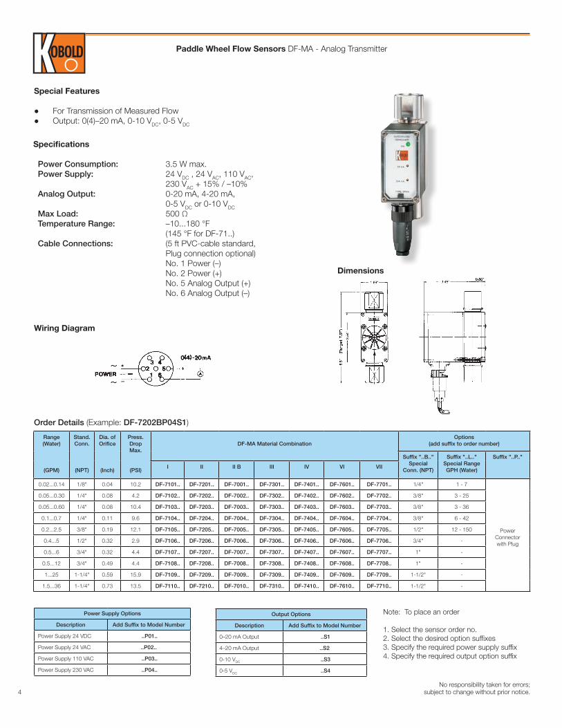
Power Consumption: 3.5 W max. Power Supply: 24 VDC , 24 VAC, 110 VAC, 230 VAC + 15% / –10% Analog Output: 0-20 mA, 4-20 mA, 0-5 VDC or 0-10 VDC Max Load: 500 Ω Temperature Range: –10...180 °F (145 °F for DF-71..) Cable Connections: (5 ft PVC-cable standard, Plug connection optional) No. 1 Power (–) No. 2 Power (+) No. 5 Analog Output (+) No. 6 Analog Output (–)
Range(Water)
(GPM)
Stand.Conn.
(NPT)
Dia. ofOrifice
(Inch)
Press.Drop Max.
(PSI)
DF-MA Material CombinationOptions
(add suffix to order number)
Suffix "..B.."Special
Conn. (NPT)
Suffix "..L.."Special Range GPH (Water)
Suffix "..P.."
I II II B III IV VI VII
0.02...0.14 1/8" 0.04 10.2 DF-7101.. DF-7201.. DF-7001.. DF-7301.. DF-7401.. DF-7601.. DF-7701.. 1/4" 1 - 7
Power Connectorwith Plug
0.05...0.30 1/4" 0.08 4.2 DF-7102.. DF-7202.. DF-7002.. DF-7302.. DF-7402.. DF-7602.. DF-7702.. 3/8" 3 - 25
0.05...0.60 1/4" 0.08 10.4 DF-7103.. DF-7203.. DF-7003.. DF-7303.. DF-7403.. DF-7603.. DF-7703.. 3/8" 3 - 36
0.1...0.7 1/4" 0.11 9.6 DF-7104.. DF-7204.. DF-7004.. DF-7304.. DF-7404.. DF-7604.. DF-7704.. 3/8" 6 - 42
0.2...2.5 3/8" 0.19 12.1 DF-7105.. DF-7205.. DF-7005.. DF-7305.. DF-7405.. DF-7605.. DF-7705.. 1/2" 12 - 150
0.4...5 1/2" 0.32 2.9 DF-7106.. DF-7206.. DF-7006.. DF-7306.. DF-7406.. DF-7606.. DF-7706.. 3/4" -
0.5...6 3/4" 0.32 4.4 DF-7107.. DF-7207.. DF-7007.. DF-7307.. DF-7407.. DF-7607.. DF-7707.. 1" -
0.5...12 3/4" 0.49 4.4 DF-7108.. DF-7208.. DF-7008.. DF-7308.. DF-7408.. DF-7608.. DF-7708.. 1" -
1...25 1-1/4" 0.59 15.9 DF-7109.. DF-7209.. DF-7009.. DF-7309.. DF-7409.. DF-7609.. DF-7709.. 1-1/2" -
1.5...36 1-1/4" 0.73 13.5 DF-7110.. DF-7210.. DF-7010.. DF-7310.. DF-7410.. DF-7610.. DF-7710.. 1-1/2" -
Order Details (Example: DF-7202BP04S1)
Output Options
Description Add Suffix to Model Number
0–20 mA Output ..S1
4–20 mA Output ..S2
0-10 VDC ..S3
0-5 VDC ..S4
Power Supply Options
Description Add Suffix to Model Number
Power Supply 24 VDC ..P01..
Power Supply 24 VAC ..P02..
Power Supply 110 VAC ..P03..
Power Supply 230 VAC ..P04..
Dimensions
Wiring Diagram
Special Features
● For Transmission of Measured Flow ● Output: 0(4)–20 mA, 0-10 VDC, 0-5 VDC
Note: To place an order
1. Select the sensor order no.2. Select the desired option suffixes3. Specify the required power supply suffix4. Specify the required output option suffix
Paddle Wheel Flow Sensors DF-MA - Analog Transmitter
5No responsibility taken for errors; subject to change without prior notice.
Specifications
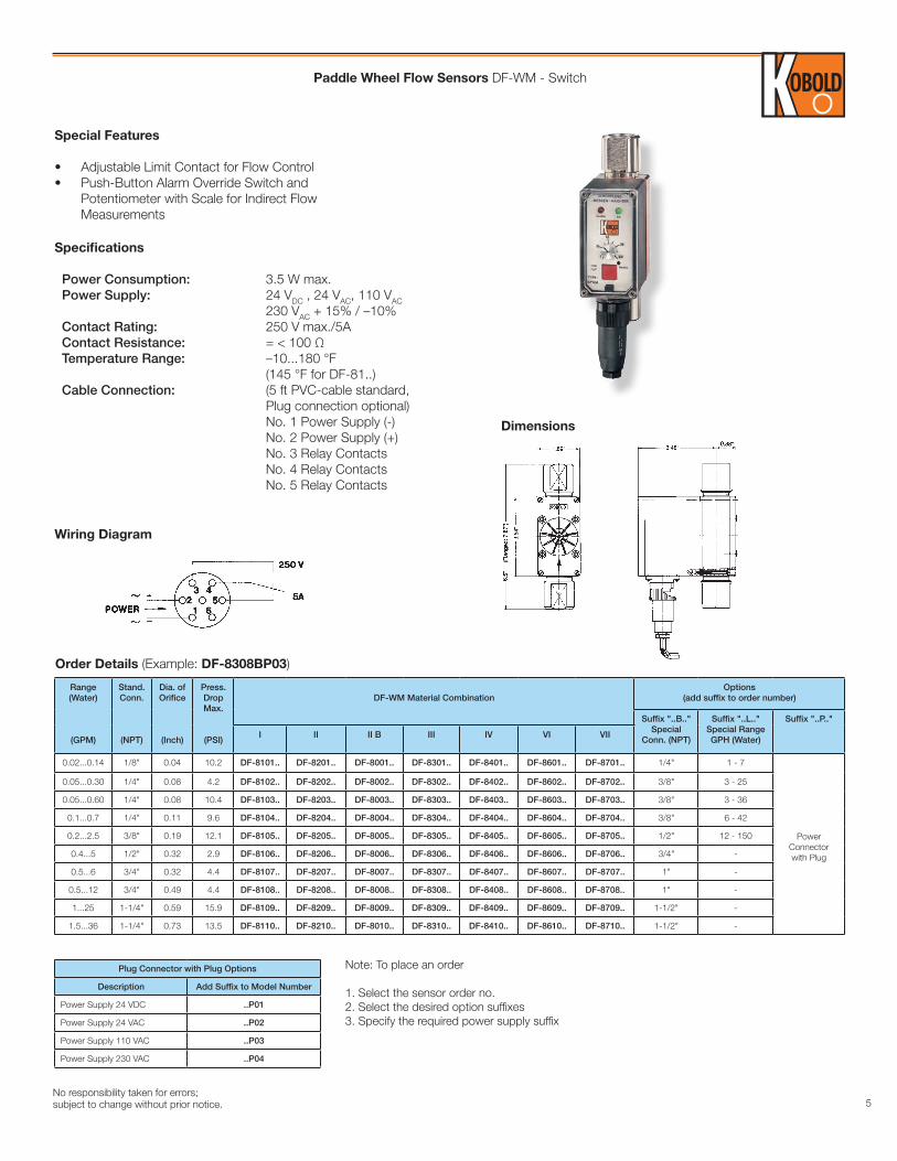
Power Consumption: 3.5 W max. Power Supply: 24 VDC , 24 VAC, 110 VAC 230 VAC + 15% / –10% Contact Rating: 250 V max./5A Contact Resistance: = < 100 Ω Temperature Range: –10...180 °F (145 °F for DF-81..) Cable Connection: (5 ft PVC-cable standard, Plug connection optional) No. 1 Power Supply (-) No. 2 Power Supply (+) No. 3 Relay Contacts No. 4 Relay Contacts No. 5 Relay Contacts
Wiring Diagram
Dimensions
Special Features
• Adjustable Limit Contact for Flow Control• Push-Button Alarm Override Switch and
Potentiometer with Scale for Indirect Flow Measurements
Range(Water)
(GPM)
Stand.Conn.
(NPT)
Dia. ofOrifice
(Inch)
Press.Drop Max.
(PSI)
DF-WM Material CombinationOptions
(add suffix to order number)
Suffix "..B.."Special
Conn. (NPT)
Suffix "..L.."Special Range GPH (Water)
Suffix "..P.."
I II II B III IV VI VII
0.02...0.14 1/8" 0.04 10.2 DF-8101.. DF-8201.. DF-8001.. DF-8301.. DF-8401.. DF-8601.. DF-8701.. 1/4" 1 - 7
PowerConnectorwith Plug
0.05...0.30 1/4" 0.08 4.2 DF-8102.. DF-8202.. DF-8002.. DF-8302.. DF-8402.. DF-8602.. DF-8702.. 3/8" 3 - 25
0.05...0.60 1/4" 0.08 10.4 DF-8103.. DF-8203.. DF-8003.. DF-8303.. DF-8403.. DF-8603.. DF-8703.. 3/8" 3 - 36
0.1...0.7 1/4" 0.11 9.6 DF-8104.. DF-8204.. DF-8004.. DF-8304.. DF-8404.. DF-8604.. DF-8704.. 3/8" 6 - 42
0.2...2.5 3/8" 0.19 12.1 DF-8105.. DF-8205.. DF-8005.. DF-8305.. DF-8405.. DF-8605.. DF-8705.. 1/2" 12 - 150
0.4...5 1/2" 0.32 2.9 DF-8106.. DF-8206.. DF-8006.. DF-8306.. DF-8406.. DF-8606.. DF-8706.. 3/4" -
0.5...6 3/4" 0.32 4.4 DF-8107.. DF-8207.. DF-8007.. DF-8307.. DF-8407.. DF-8607.. DF-8707.. 1" -
0.5...12 3/4" 0.49 4.4 DF-8108.. DF-8208.. DF-8008.. DF-8308.. DF-8408.. DF-8608.. DF-8708.. 1" -
1...25 1-1/4" 0.59 15.9 DF-8109.. DF-8209.. DF-8009.. DF-8309.. DF-8409.. DF-8609.. DF-8709.. 1-1/2" -
1.5...36 1-1/4" 0.73 13.5 DF-8110.. DF-8210.. DF-8010.. DF-8310.. DF-8410.. DF-8610.. DF-8710.. 1-1/2" -
Plug Connector with Plug Options
Description Add Suffix to Model Number
Power Supply 24 VDC ..P01
Power Supply 24 VAC ..P02
Power Supply 110 VAC ..P03
Power Supply 230 VAC ..P04
Note: To place an order
1. Select the sensor order no.2. Select the desired option suffixes3. Specify the required power supply suffix
Order Details (Example: DF-8308BP03)
Paddle Wheel Flow Sensors DF-WM - Switch
6No responsibility taken for errors;
subject to change without prior notice.
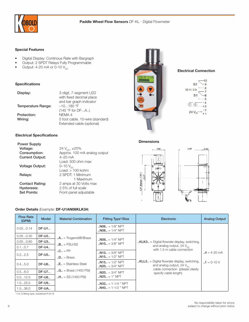
Paddle Wheel Flow Sensors DF-KL - Digital Flowmeter
Specifications
Display: 3-digit, 7-segment LED with fixed decimal place and bar graph indicator Temperature Range: –10...180 °F (145 °F for DF-..A..) Protection: NEMA 4 Wiring: 5 foot cable, 10-wire (standard) Extended cable (optional)
Order Details (Example: DF-U1AN06KLK34)
Dimensions
Special Features
• Digital Display: Continous Rate with Bargraph• Output: 2 SPDT Relays Fully Programmable• Output: 4-20 mA or 0-10 VDC
Electrical Connection
Flow Rate(GPM)
Model Material Combination Fitting Type*/Size Electronic Analog Output
0.02...0.14 DF-U1..
..A.. = Trogamid®/Brass
..B.. = PSU/SS
..C.. = PP
..D.. = Brass
..E.. = Stainless Steel
..G.. = Brass (1450 PSI)
..H.. = SS (1450 PSI)
..N06.. = 1/8" NPT
..N08.. = 1/4" NPT
..KLK3.. = Digital flowrate display, switching, and analog output, 24 VDC
with 1.5 m cable connection
..KLL3.. = Digital flowrate display, switching, and analog output, 24 VDC
cable connection (please clearly specify cable length)
..4 = 4-20 mA
..1 = 0-10 V
0.05...0.30 DF-U2....N08.. = 1/4" NPT..N10.. = 3/8" NPT
0.05...0.60 DF-U3..
0.1...0.7 DF-U4..
0.2...2.5 DF-U5....N10.. = 3/8" NPT..N15.. = 1/2" NPT
0.4...5.0 DF-U6....N15.. = 1/2" NPT..N20.. = 3/4" NPT
0.5...6.0 DF-U7.. ..N20.. = 3/4" NPT..N25.. = 1" NPT0.5...12.0 DF-U8..
1.0...25.0 DF-U9.. ..N32.. = 1-1/4 " NPT..N40.. = 1-1/2 " NPT1.5...36.0 DF-UA..
Electrical Specifications
Power Supply Voltage: 24 VDC, ±20% Consumption: Approx. 100 mA analog output Current Output: 4–20 mA Load: 500 ohm max Voltage Output: 0–10 VDC Load: > 100 kohm Relays: 2 SPDT: 1 Minimum 1 Maximum Contact Rating: 2 amps at 30 Volts max Hysteresis: 2.5% of full scale Set Points: Front panel adjustable
* For G fitting type, substitute R for N
7No responsibility taken for errors; subject to change without prior notice.
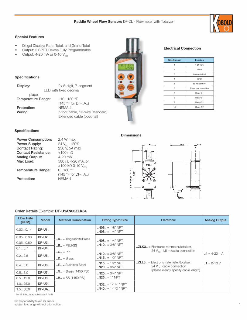
Paddle Wheel Flow Sensors DF-ZL - Flowmeter with Totalizer
Specifications
Power Consumption: 2.4 W max. Power Supply: 24 VDC, ±20% Contact Rating: 250 V, 5A max Contact Resistance: <100 mΩ Analog Output: 4-20 mA Max Load: 500 Ω, 4-20 mA, or >100 kΩ 0-10 VDC Temperature Range: 0...180 °F (145 °F for DF-..A..) Protection: NEMA 4
Special Features
• Ditigal Display: Rate, Total, and Grand Total• Output: 2 SPDT Relays Fully Programmable• Output: 4-20 mA or 0-10 VDC
Electrical Connection
Dimensions
Wire Number Function
1 + 24 VDC
2 GND
3 Analog output
4 GND
5 do not connect
6 Reset part quantities
7 Relay S1
8 Relay S1
9 Relay S2
10 Relay S2
Order Details (Example: DF-U1AN06ZLK34)
Specifications
Display: 2x 8-digit, 7-segment LED with fixed decimal place Temperature Range: –10...180 °F (145 °F for DF-..A..) Protection: NEMA 4 Wiring: 5 foot cable, 10-wire (standard) Extended cable (optional)
Flow Rate(GPM)
Model Material Combination Fitting Type*/Size Electronic Analog Output
0.02...0.14 DF-U1..
..A.. = Trogamid®/Brass
..B.. = PSU/SS
..C.. = PP
..D.. = Brass
..E.. = Stainless Steel
..G.. = Brass (1450 PSI)
..H.. = SS (1450 PSI)
..N06.. = 1/8" NPT
..N08.. = 1/4" NPT
..ZLK3.. = Electronic ratemeter/totalizer, 24 VDC, 1.5 m cable connection
..ZLL3.. = Electronic ratemeter/totalizer, 24 VDC, cable connection (please clearly specify cable length)
..4 = 4-20 mA
..1 = 0-10 V
0.05...0.30 DF-U2....N08.. = 1/4" NPT..N10.. = 3/8" NPT
0.05...0.60 DF-U3..
0.1...0.7 DF-U4..
0.2...2.5 DF-U5....N10.. = 3/8" NPT..N15.. = 1/2" NPT
0.4...5.0 DF-U6....N15.. = 1/2" NPT..N20.. = 3/4" NPT
0.5...6.0 DF-U7.. ..N20.. = 3/4" NPT..N25.. = 1" NPT0.5...12.0 DF-U8..
1.0...25.0 DF-U9.. ..N32.. = 1-1/4 " NPT..N40.. = 1-1/2 " NPT1.5...36.0 DF-UA..
* For G fitting type, substitute R for N
8No responsibility taken for errors;
subject to change without prior notice.
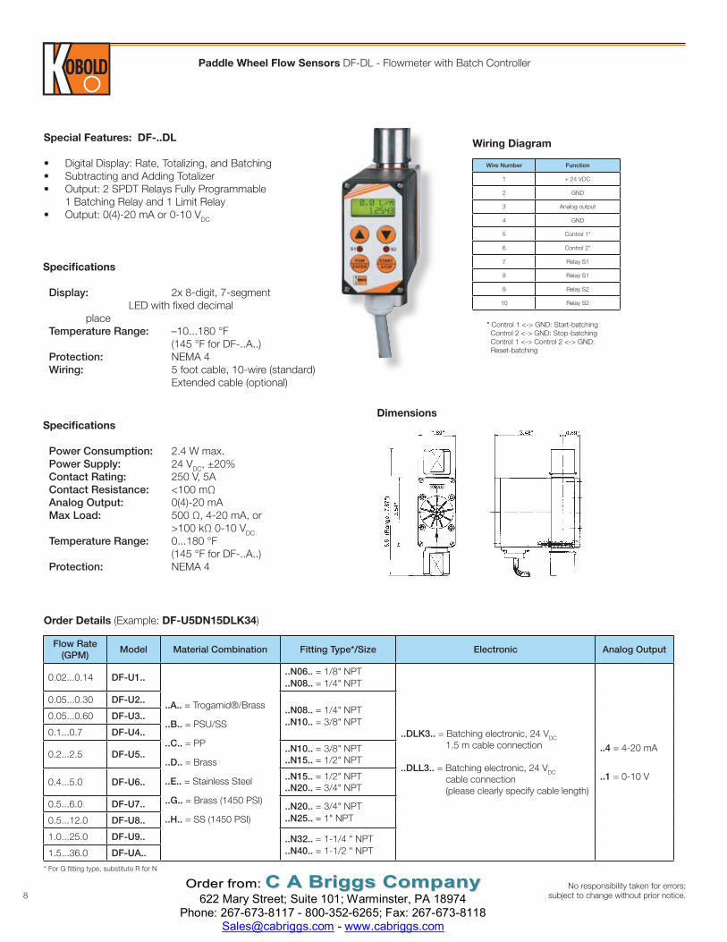
Paddle Wheel Flow Sensors DF-DL - Flowmeter with Batch Controller
Order Details (Example: DF-U5DN15DLK34)
Dimensions
Wiring DiagramSpecial Features: DF-..DL
• Digital Display: Rate, Totalizing, and Batching• Subtracting and Adding Totalizer• Output: 2 SPDT Relays Fully Programmable
1 Batching Relay and 1 Limit Relay• Output: 0(4)-20 mA or 0-10 VDC
Specifications
Power Consumption: 2.4 W max. Power Supply: 24 VDC, ±20% Contact Rating: 250 V, 5A Contact Resistance: <100 mΩ Analog Output: 0(4)-20 mA Max Load: 500 Ω, 4-20 mA, or >100 kΩ 0-10 VDC Temperature Range: 0...180 °F (145 °F for DF-..A..) Protection: NEMA 4
Wire Number Function
1 + 24 VDC
2 GND
3 Analog output
4 GND
5 Control 1*
6 Control 2*
7 Relay S1
8 Relay S1
9 Relay S2
10 Relay S2
* Control 1 <-> GND: Start-batching Control 2 <-> GND: Stop-batching Control 1 <-> Control 2 <-> GND: Reset-batching
Flow Rate(GPM)
Model Material Combination Fitting Type*/Size Electronic Analog Output
0.02...0.14 DF-U1..
..A.. = Trogamid®/Brass
..B.. = PSU/SS
..C.. = PP
..D.. = Brass
..E.. = Stainless Steel
..G.. = Brass (1450 PSI)
..H.. = SS (1450 PSI)
..N06.. = 1/8" NPT
..N08.. = 1/4" NPT
..DLK3.. = Batching electronic, 24 VDC 1.5 m cable connection
..DLL3.. = Batching electronic, 24 VDC cable connection (please clearly specify cable length)
..4 = 4-20 mA
..1 = 0-10 V
0.05...0.30 DF-U2....N08.. = 1/4" NPT..N10.. = 3/8" NPT
0.05...0.60 DF-U3..
0.1...0.7 DF-U4..
0.2...2.5 DF-U5....N10.. = 3/8" NPT..N15.. = 1/2" NPT
0.4...5.0 DF-U6....N15.. = 1/2" NPT..N20.. = 3/4" NPT
0.5...6.0 DF-U7.. ..N20.. = 3/4" NPT..N25.. = 1" NPT0.5...12.0 DF-U8..
1.0...25.0 DF-U9.. ..N32.. = 1-1/4 " NPT..N40.. = 1-1/2 " NPT1.5...36.0 DF-UA..
* For G fitting type, substitute R for N
Specifications
Display: 2x 8-digit, 7-segment LED with fixed decimal place Temperature Range: –10...180 °F (145 °F for DF-..A..) Protection: NEMA 4 Wiring: 5 foot cable, 10-wire (standard) Extended cable (optional)
OOrrddeerr ffrroomm:: CC AA BBrriiggggss CCoommppaannyy 622 Mary Street; Suite 101; Warminster, PA 18974
Phone: 267-673-8117 - 800-352-6265; Fax: 267-673-8118 [email protected] - www.cabriggs.com


