Download - manual DIALux 4.9.0.0
DIALux
Version 4.7 The Software Standard for
Calculating Lighting Layouts
User Manual
DIALux Version 4.7
DIAL GmbH, Lüdenscheid page 2
© 2009 DIAL GmbH Gustav-Adolf-Straße 4 58507 Lüdenscheid [email protected] www.dial.de 15th Edition 2009 The text and images were prepared with great care. DIAL, the authors and the translators are, however, not subject to legal obligation or liability for any erroneous information and its consequences. This publication is protected by copyright law. All rights are reserved. Most of the soft-ware and hardware designations used in this manual are registered trademarks and therefore subject to the applicable laws. The DIAL GmbH can not be held responsible for any damage to people or property which might occur in connection with the use of the DIALux software. The program and documentation was created with great care, however errors cannot be ruled out. POV-Ray™ POV-Ray™ is short for the Persistence of Vision™ Raytracer, a tool for producing high-quality computer graphics. POV-Ray™ is copyrighted freeware, that is to say, we, the authors, retain all rights and copyright over the program, but that we permit you to use it for no charge, subject to the conditions stated in our license. You can read the license by viewing the POV-Ray for Windows About box by using the Help menu or Alt+B and selecting the appropriate button. CONTACT INFORMATION for POV-Ray™ License inquiries can be made via email; please check the POV-Ray™ website and the online copy of this document at http://www.povray.org/povlegal.html for the current email address of the team leader. (Unfortunately we cannot include it here as we have to change it from time to time due to spam email being sent to the address). The following postal address is only to be used for official license business when emailing is impossible. We do not provide technical support. We will not mail you disks with updated versions. Please do not send money. If you want to know how to support us, please see http://www.povray.org/supporting-povray.html. POV-Team C/O Hallam Oaks P/L PO Box 407 Williamstown, Victoria 3016 Australia MESA Copyright (C) 1999-2003 Brian Paul All Rights Reserved.
THE SOFTWARE IS PROVIDED "AS IS", WITHOUT WARRANTY OF ANY KIND, EXPRESS OR IMPLIED, INCLUDING BUT NOT LIMITED TO THE WARRANTIES OF MERCHANTABILITY, FITNESS FOR A PARTICULAR PURPOSE AND NONINFRINGEMENT. IN NO EVENT SHALL BRIAN PAUL BE LIABLE FOR ANY CLAIM, DAMAGES OR OTHER LIABILITY, WHETHER IN AN ACTION OF CONTRACT, TORT OR OTHERWISE, ARISING FROM, OUT OF OR IN CONNECTION WITH THE SOFTWARE OR THE USE OR OTHER DEALINGS IN THE SOFTWARE.
Registered Trademarks: Microsoft, MS, Windows, Windows NT, Win32 are registered trademarks of the Microsoft Corporation in the USA and other countries. Adobe, Acrobat Reader are registered trademarks of Adobe Systems, INC. "POV-Ray™", "Persistence of Vision", "POV-Team™" and "POV-Help" are trademarks of the POV-Team™. Any other trademarks referred to herein are the property of their respective holders.
DIALux Version 4.7
DIAL GmbH, Lüdenscheid page 3
DIALux Version 4.7
The Software Standard for
Calculating Lighting Layouts
Function Overview Welcome to DIALux 4.7 This manual is intended to assist you to work fast and effectively with DIALux. If you have experience with Windows applications, getting started in DIALux will present no problem. DIAL regularly offer courses where the professional use of DIALux can be learned. Information regarding the course dates and contents are available under www.dialux.com and www.dial.de or +49 (0) 2351 1064 360. Latest information and updates are also available on our homepage. In the following you will find a short description of the functions available in DIALux.
DIALux offers a number of textures that you are free to use for your lighting layouts. The following companies provided those textures: Texturenliste SuperFinish – Immobiliendarstellungen, Jochen
Schroeder/ www.immobiliendarstellung.de Arroway Texturen/ www.arroway.de Ulf Theis/ www.ulf-theis.de Texturenland (Konstantin Gross)/ www.texturenland.de Noctua Graphics (Herbert Fahrnholz)/ www.noctua-graphics.de Thermopal/ www.thermopal.de Rathscheck Schiefer und Dachsysteme KG/ www.rathscheck.de They offer many more textures. Check their websites for further textures.
DIALux Version 4.7
DIAL GmbH, Lüdenscheid page 4
Contents Contents .......................................................................4 New functions in DIALux Version 4.7...........................10
New features and improvements .............................10 Changes in existing functionality..............................10
Installation ..................................................................12 Installation after Internet Download.........................12 Installation from CD.................................................13
Online Menu ...............................................................14 Online Update .........................................................14 Manage Newsletter subscription ..............................14 Wishes and Feedback / Send problem report............14
Install Luminaire Data ..................................................15 About PlugIns ..........................................................15 Online update of luminaire catalogues.....................15 About Online Catalogues.........................................16 Lamp PlugIns ...........................................................16
DIALux directories .......................................................17 Background information ..........................................17 Furniture, textures, my database ..............................17
Windows Vista ............................................................17 Projects and raytracing files......................................17
Windows Vista ............................................................17 Program files, support..............................................18
Windows 2000, XP, Vista ............................................18 Common used program files (DIALux, PlugIns) .........18
Windows 2000, XP, Vista ............................................18 DIALux Light................................................................19 Working with Wizards.................................................25 The DIALux User Interface ...........................................34
The Project manager................................................38 The Luminaire Selection ...........................................39 The User Database...................................................40 Insert Luminaire Files into DIALux.............................40 Lamp PlugIns ...........................................................41 The Furniture Tree ...................................................44 The Colours Tree (since version 4.3, formerly Texture Tree)........................................................................44 The Output Tree ......................................................46 The Guide................................................................47 The Inspector...........................................................48 Edit Mode................................................................50
Optimise Personal Settings ..........................................54 General Options ......................................................54 Direct3D as an alternative to OpenGL ......................56
Create a New Project...................................................60 Open a new project .................................................61 Project information in the file open dialog ...............62
Edit Rooms..................................................................63 Edit Room Geometry ...............................................63 Edit Room Data .......................................................64 An easy method for determining maintenance factor...............................................................................65
DIALux Version 4.7
DIAL GmbH, Lüdenscheid page 5
Extended method for determining maintenance factor...............................................................................67 Modify Properties of Individual Walls .......................75
Insert Room Elements..................................................77 Modify a Room with Room Elements .......................77 Vault and half vault .................................................80 Insert via Property Page............................................80
Insert Furniture............................................................81 Insert Furniture ........................................................81 Insert via Property Page............................................81 Create Furniture ......................................................81 Import Furniture and 3D model Files ........................84 Extrusion Volumes ...................................................85 Glass objects............................................................86 Subtraction of Objects .............................................87 Selecting Single Surfaces..........................................88 Windows and Doors ................................................89 Decoration Objects ..................................................89 Insert Decoration Objects.........................................90 Calculate with Decoration Objects ...........................91
Insert Textures.............................................................92 Insert via Drag & Drop .............................................92 Edit Placed Textures .................................................92 Delete Textures........................................................93 Import Textures into the Texture Tree ...................... 93 Edit Room Geometry with DWG or DXF-File.............94
Material dialogue for surfaces .....................................95 Colour .....................................................................95 Reflection (Rho) .......................................................95 Transparency ...........................................................95 Calculation of transparency .....................................96 Roughness...............................................................96 Mirror effect ............................................................96 Material...................................................................96 Raytrace preview .....................................................96
Duplicate (Copy Rooms/Scenes/Streets) .......................99 Duplicate an Existing Room......................................99
Insert and Edit Luminaires and Luminaire Arrangements.................................................................................100
Online Catalogues .................................................101 Individual Luminaires .............................................101 Aligning Luminaires ...............................................104 Inserting Luminaire Fields.......................................106 Inserting Luminaire Lines........................................110 Aligning Lights.......................................................112 Inserting Luminaire Circles .....................................112 Separating Luminaire Arrangements ......................113 Floodlighting .........................................................113 Inserting floodlight illumination .............................113 Arranging floodlighting .........................................115 Focal points ...........................................................115 Modify the position of a Luminaire ........................117 Luminaires with articulated joints...........................118 Luminaires with several articulated joints ...............119
DIALux Version 4.7
DIAL GmbH, Lüdenscheid page 6
Unrestricted lighting arrangements ........................119 Aligning luminaire arrangements ...........................121 Calculation of luminaire geometry included ...........122
Illumination strategies ...............................................123 Insertion of luminaries with “direct planar lighting”.............................................................................123 Insertion of luminaries with “vertical planar lighting”.............................................................................126
Coloured light ...........................................................129 Background information ........................................129 Lamp spectrum / Light colours ...............................130 Colour filters..........................................................135 Coaction of spectral distribution of the light source and colour filter .....................................................136 Light colours in the ray tracing...............................137 White balance .......................................................137
Light Scenes and Control Groups ..............................139 Definition ..............................................................139 Requirements ........................................................139 Generate a project with light scenes and control groups...................................................................139 Modify light scenes and control groups..................146 Export of light scenes.............................................148
Emergency lighting....................................................149 Global ...................................................................149 Escape route lighting .............................................151 Open area lighting (anti panic)...............................153 High risk task area lighting.....................................156 Luminaires with emergency lights ..........................156 Emergency lighting data sheet ...............................157
Daylight calculation in DIALux ...................................158 Basics ....................................................................158 Sky types in DIALux................................................158 Light Scenes ..........................................................159 Daylight calculation ...............................................160 Obstruction ...........................................................162 Sun and shadow visualisation ................................163 Settings in the calculation dialogue........................163
Working in the 3D View............................................165 Setup the 3D View.................................................165 Check Calculation Values in the 3D View...............166 Save 3D View ........................................................167 Presentation of false colour rendering....................169
Working in Various Views..........................................170 Save 3D CAD views ...............................................171
Wireframe Model ......................................................173 Editing Inserted Objects.............................................174
Moving Objects .....................................................174 Moving and Rotating Objects without Pick Grid .....175 Scale or rotate .......................................................176 Rotating Objects ....................................................177 Scaling Objects ......................................................177 Combining and Saving Objects ..............................178 Moving the Coordinate Origin of an Object ...........178
DIALux Version 4.7
DIAL GmbH, Lüdenscheid page 7
Resetting the rotation of the origin ........................179 Editing Object Surfaces ..........................................180
Arrangement aids......................................................182 Measurement of distances .....................................182 Working with the snap grid ...................................183 Automatic help lines ..............................................183 Helping areas defined in the ruler ..........................184 Working with help lines .........................................185 Simple help lines....................................................186 Poly help lines........................................................187 Spline help line ......................................................188 Circular help line....................................................189 Help grids ..............................................................190 Copy and paste with CTRL+C, CTRL+V and CTRL+H.............................................................................192 Copy Along a Line .................................................192 Align and distribute ...............................................193 Centre objects in the room ....................................194
Calculation Surfaces and other Calculation Objects ...195 Calculation Surfaces ..............................................195 Calculation surfaces for different types of illuminance.............................................................................196 Penetration............................................................196 Task Areas .............................................................197 Calculation grids....................................................197 Editing...................................................................199 Scaling...................................................................201 Merging calculation grids.......................................202 Calculation points in calculation grids ....................202 Measuring grids.....................................................204 Calculation ............................................................205 Gradients...............................................................206 Display settings......................................................207 Real time calculation..............................................207 Isolines ..................................................................209 Calculation Points ..................................................210 UGR Calculation ....................................................211 Insert UGR Calculation Point and UGR Calculation Area ......................................................................211 Adjust Viewing Direction of UGR Observer and UGR Area ......................................................................212
Exterior Lighting ........................................................213 Exterior Scenes ......................................................213 Ground Elements...................................................214 Floodlight Illumination ...........................................215
Lighting Design according to prEN12464 Part 2 / EN8995-2..................................................................216
Glare Rating ..........................................................216 Obtrusive Light / ULR Calculation ...........................217 Obtrusive Light / Luminous Intensity Calculation Point.............................................................................218
Street Valuation Fields in Exterior Scenes ...................219 Road lighting.............................................................221
Standard Streets ....................................................221
DIALux Version 4.7
DIAL GmbH, Lüdenscheid page 8
Quick Street Planning Wizard.................................222 Wizard Optimised Street Light Arrangement ..........227 Street Planning without Wizard .............................229 Illumination Conditions Wizard ..............................230 Illumination Class Wizard.......................................239 Importing R-tables .................................................244 Street Illumination .................................................245 Luminance Calculation according to DIN 5044.......251
Sports complexes ......................................................253 Inserting a sports complex .....................................253 Editing a sports complex ........................................254 Initial calculation grids ...........................................255 Pole positions ........................................................256 TV cameras............................................................256 Outputs .................................................................257
Global Output Settings..............................................259 User Data and Project Data ....................................259 Global Settings ......................................................260
Output ......................................................................261 Viewing Calculation Results ...................................261 Limit Result Output................................................262 Output Settings .....................................................263 New Output in DIALux...........................................264 Luminaire Data Sheet.............................................265 Luminance Diagram...............................................265 Tabular Presentation of Photometric Data of Luminaires .............................................................266 Tabular Presentation of Exterior Scenes..................266 Creating User-Defined Standard Output ................267 Save Output as PDF-File .........................................268 Export Output Graphics, tables, text and graphic ...269
DWG and DXF Import and Export..............................271 DWG / DXF-Import ................................................271 Basic DWG / DXF Settings and Layer Selection .......271 Edit a Room based on the DWG / DXF-Ground Plan.............................................................................272 Working with the DWG / DXF Background in the 3D View......................................................................273 DWG / DXF-Export.................................................274
STF Interface .............................................................280 Energy Performance of Buildings ...............................281
Background information ........................................281 Why energy evaluation in DIALux?.........................281 Structure of an energy evaluation project...............283 Energy evaluation rooms with and without links to DIALux rooms ........................................................287 Working on parameters .........................................290 Calculation and results...........................................293 Documentation of energy evaluation results ..........295
Making videos in DIALux ...........................................298 Raytracer...................................................................302
Background ...........................................................302 POV-Ray Settings within DIALux.............................302 Photo Realistic Images with Raytracing...................302
DIALux Version 4.7
DIAL GmbH, Lüdenscheid page 9
Basic Settings.........................................................302 Quick preferences..................................................303 Image preferences .................................................305 Indirect calculation.................................................305 Brightness preferences...........................................307 Raytracing-Options for Surfaces .............................308 3-D Standard View for Raytracing ..........................309 Starting POV-Ray ...................................................309 Manipulation of the POV file and editing in POV-Ray.............................................................................311 Start of the adapted POV-Ray Version....................311 Smoothing edges...................................................311 Picture ratio ...........................................................312 Camera .................................................................314 Animation .............................................................316
Animation with Keyframes ........................................316 Translation animation ............................................319 Colour ...................................................................321 Further functions of POV-Ray.................................321
List of figures ............................................................328 Index.........................................................................339 Appendix A Keyboard Short Cuts ..............................342
DIALux Version 4.7
DIAL GmbH, Lüdenscheid page 10
New functions in DIALux Version 4.7 The DIALux version 4.7 has the following new features:
New features and improvements Calculation of transparency
Since DIALux 4.7 the calculation of transparent objects is available. Therefore the feature “glass plate” has been established. By using a glass plate you are able to calculate scenes correctly which weren’t calculable in previous DIALux versions – e.g. you will get results for light which falls through a (semi-)transparent room-divider. As a matter of fact you can use the newly integrated feature with the common standard elements and/or imported models as well. Please be informed that the calculation does not include the effect of light refraction! Within DIALux 3D standard view transparency is not visible.
Quick preview of transparency and reflection
Transparency and reflection has been usable in our previous DIALux versions with Raytracer Pov-Ray, which comes amongst others with DIALux. Since DIALux 4.7 you are able to generate pictures with effects of transparency and reflection directly in DIALux. To achieve impressive results it only takes a minimal amount of time and effort from now on.
Online update of manufacturers information
DIALux is capable to update luminaire catalogues directly from the internet – the same procedure as with online catalogues. By right-clicking onto “DIALux luminaire catalogues” or “Not installed catalogues”, within the luminaire selection, DIALux downloads the latest information available.
Changes in existing functionality DWG-/DXF Export
Additionally to the already available features in DIALux (writing into DWG and DXF files) version 4.7 is capable to export the results of calculation grids and calculation points as well.
Direct calculation
Calculation grids allow you to get calculation results in real time directly into the CAD – without considering reflections. Newly integrated in DIALux
DIALux Version 4.7
DIAL GmbH, Lüdenscheid page 11
4.7 is the output of constancy (Emin / Emedium and
Emin / Emax) also directly into the CAD. Output for radial and uneven distanced
calculation grids Particularly projects of great size need a clear illustration of calculation outputs - DIALux 4.7 meets this demand especially for radial and uneven distanced calculation grids.
New standards for street lighting
The list of street lighting classes for calculation grids in DIALux has been extended by Danish classes (L1 – L7, LE2 – 5 and E1 – E3) and South African classes (A1a – A4f).
Arrow of flood light arrangement In previous DIALux versions the illumination points of a flood light arrangement was modified in height if the beam angle has been changed. Since DIALux 4.7 the beam point is lowered to the ground space (z=0) at all times. The arrow of a flood light arrangement maintains his length if the ground cannot be hit. The maximum length of an arrow is 999m.
Various translations At various passages the translation of DIALux manual has been reworked.
Various bug fixes Due to the strong participation of our users in the DIALux-Forum (www.dialux.com) different smaller bugs in DIALux could have been fixed. Thank you!
DIALux Version 4.7
DIAL GmbH, Lüdenscheid page 12
Installation The installation of DIALux is easy to do. Please close all other application programmes before installing DIALux.
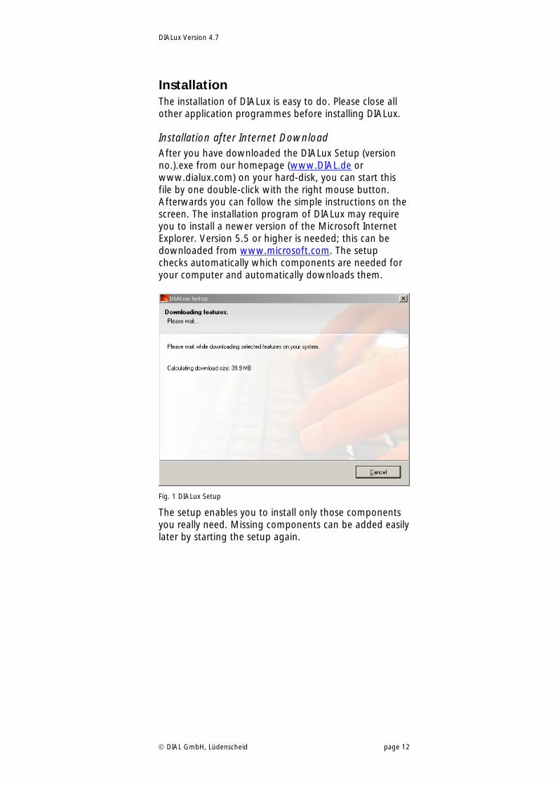
Installation after Internet Download After you have downloaded the DIALux Setup (version no.).exe from our homepage (www.DIAL.de or www.dialux.com) on your hard-disk, you can start this file by one double-click with the right mouse button. Afterwards you can follow the simple instructions on the screen. The installation program of DIALux may require you to install a newer version of the Microsoft Internet Explorer. Version 5.5 or higher is needed; this can be downloaded from www.microsoft.com. The setup checks automatically which components are needed for your computer and automatically downloads them.
Fig. 1 DIALux Setup
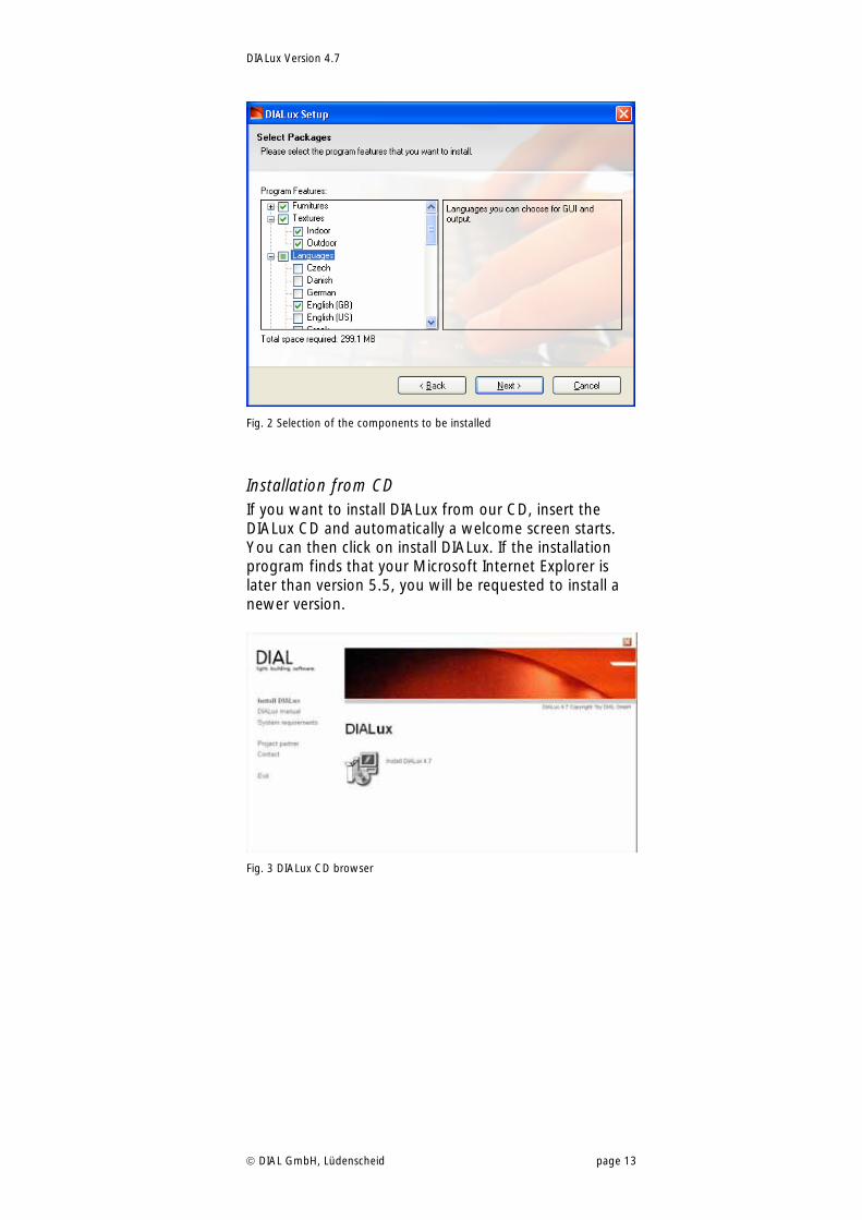
The setup enables you to install only those components you really need. Missing components can be added easily later by starting the setup again.
DIALux Version 4.7
DIAL GmbH, Lüdenscheid page 13
Fig. 2 Selection of the components to be installed
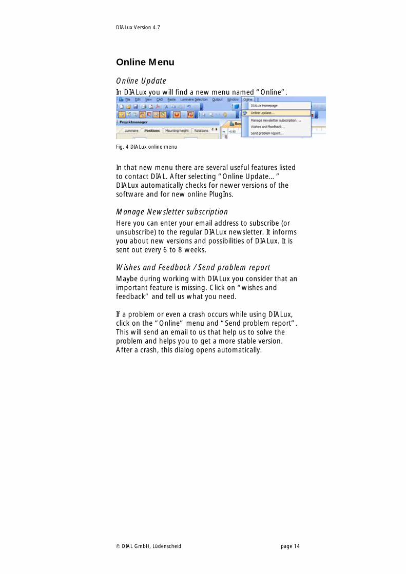
Installation from CD If you want to install DIALux from our CD, insert the DIALux CD and automatically a welcome screen starts. You can then click on install DIALux. If the installation program finds that your Microsoft Internet Explorer is later than version 5.5, you will be requested to install a newer version.
Fig. 3 DIALux CD browser
DIALux Version 4.7
DIAL GmbH, Lüdenscheid page 14
Online Menu
Online Update In DIALux you will find a new menu named “Online”.
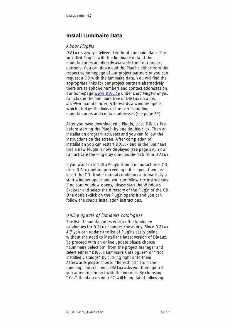
Fig. 4 DIALux online menu
In that new menu there are several useful features listed to contact DIAL. After selecting “Online Update…” DIALux automatically checks for newer versions of the software and for new online PlugIns.
Manage Newsletter subscription Here you can enter your email address to subscribe (or unsubscribe) to the regular DIALux newsletter. It informs you about new versions and possibilities of DIALux. It is sent out every 6 to 8 weeks.
Wishes and Feedback / Send problem report Maybe during working with DIALux you consider that an important feature is missing. Click on “wishes and feedback” and tell us what you need. If a problem or even a crash occurs while using DIALux, click on the “Online” menu and “Send problem report”. This will send an email to us that help us to solve the problem and helps you to get a more stable version. After a crash, this dialog opens automatically.
DIALux Version 4.7
DIAL GmbH, Lüdenscheid page 15
Install Luminaire Data
About PlugIns DIALux is always delivered without luminaire data. The so-called PlugIns with the luminaire data of the manufacturers are directly available from our project partners. You can download the PlugIns either from the respective homepage of our project partners or you can request a CD with the luminaire data. You will find the appropriate links for our project partners alternatively there are telephone numbers and contact addresses on our homepage www.DIAL.de under Data PlugIns or you can click in the luminaire tree of DIALux on a not installed manufacturer. Afterwards a window opens, which displays the links of the corresponding manufacturers and contact addresses (see page 39). After you have downloaded a PlugIn, close DIALux first before starting the PlugIn by one double-click. Then an installation program activates and you can follow the instructions on the screen. After completion of installation you can restart DIALux and in the luminaire tree a new PlugIn is now displayed (see page 39). You can activate the PlugIn by one double-click from DIALux. If you want to install a PlugIn from a manufacturers CD, close DIALux before proceeding if it is open, then just insert the CD. Under normal conditions automatically a start window opens and you can follow the instructions. If no start window opens, please start the Windows Explorer and select the directory of the PlugIn of the CD. One double-click on the PlugIn opens it and you can follow the simple installation instructions.
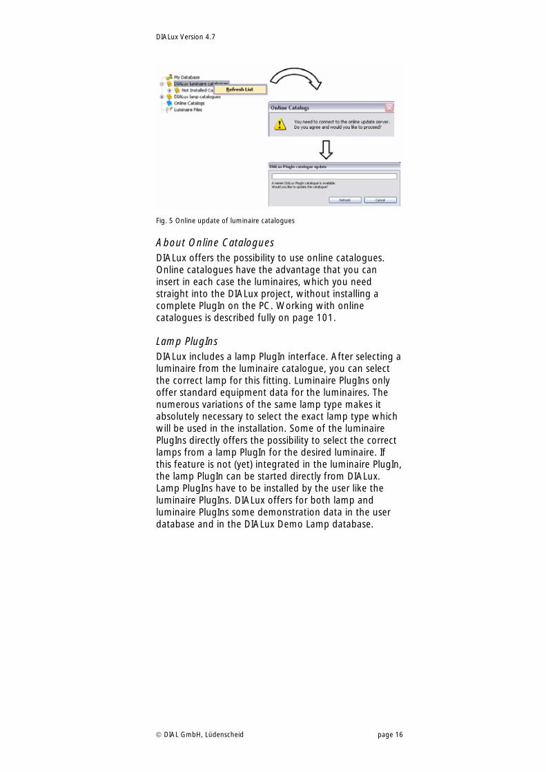
Online update of luminaire catalogues The list of manufacturers which offer luminaire catalogues for DIALux changes constantly. Since DIALux 4.7 you can update the list of PlugIns easily online without the need to install the latest version of DIALux. To proceed with an online update please choose “Luminaire Selection” from the project manager and select either “DIALux Luminaire Catalogues” or “Not Installed Catalogs” by clicking right onto them. Afterwards please choose “Refresh list” from the opening context menu. DIALux asks you thereupon if you agree to connect with the internet. By choosing “Yes” the data on your PC will be updated following.
DIALux Version 4.7
DIAL GmbH, Lüdenscheid page 16
Fig. 5 Online update of luminaire catalogues
About Online Catalogues DIALux offers the possibility to use online catalogues. Online catalogues have the advantage that you can insert in each case the luminaires, which you need straight into the DIALux project, without installing a complete PlugIn on the PC. Working with online catalogues is described fully on page 101.
Lamp PlugIns DIALux includes a lamp PlugIn interface. After selecting a luminaire from the luminaire catalogue, you can select the correct lamp for this fitting. Luminaire PlugIns only offer standard equipment data for the luminaires. The numerous variations of the same lamp type makes it absolutely necessary to select the exact lamp type which will be used in the installation. Some of the luminaire PlugIns directly offers the possibility to select the correct lamps from a lamp PlugIn for the desired luminaire. If this feature is not (yet) integrated in the luminaire PlugIn, the lamp PlugIn can be started directly from DIALux. Lamp PlugIns have to be installed by the user like the luminaire PlugIns. DIALux offers for both lamp and luminaire PlugIns some demonstration data in the user database and in the DIALux Demo Lamp database.
DIALux Version 4.7
DIAL GmbH, Lüdenscheid page 17
DIALux directories
Background information Microsoft has more and more strictly separated the user and the administrator privileges in Windows Vista and XP. So misuse of the computer by unauthorized persons or by malware was complicated. On the other hand users, administrators and manufacturer of software are more and more forced to follow the guidelines of the operating system strictly. To make sure that also users with restricted privileges can use DIALux with all its features it was necessary to change some directories used by DIALux.
Furniture, textures, my database These directories are now placed in the “application data common folder”. This standard directory can be changed by the administrator. The following examples are standard settings after a windows installation. Windows XP, Windows 2000 C:\documents and settings\All Users\application data\DIALux Drive is the system drive (standard: C:) subdirectory „documents and settings“ is localized,
(Standard: „Documents and Settings“) subdirectory application data is localised and hidden
(Standard: „Application Data“) Windows Vista C:\ProgramData\DIALux Drive is the systemdrive (standard: C:) subdirectory „ProgrammData“ is hidden
Projects and raytracing files Since DIALux 4.4 the DIALux project files and the raytracing files are stored in the “my documents” folder. This was necessary to make sure, that users with restricted privileges can load and save files. Windows XP, Windows 2000 C:\documents and settings\”user name” \my documents\DIALux Drive is the system drive (standard: C:) subdirectory „my documents “ is localized,
(Standard: „my documents“) Windows Vista C:\User\”user name”\documents\DIALux Drive is the systemdrive (standard: C:) subdirectory „user“ is localized
DIALux Version 4.7
DIAL GmbH, Lüdenscheid page 18
subdirectory „documents“ is localized
Program files, support The DIALux directory is placed in the “Program files” folder. This standard directory can be changed by the administrator. The following examples are standard settings after a windows installation. Windows 2000, XP, Vista C:\Program files\DIALux Drive is the systemdrive (standard: C:) subdirectory „program files“ is localized
Common used program files (DIALux, PlugIns) The DIALux directory is placed in the “Program files” folder. This standard directory can be changed by the administrator. The following examples are standard settings after a windows installation. Windows 2000, XP, Vista C:\program files\common files\DIALux Drive is the systemdrive (standard: C:) subdirectory „program files“ is localized
DIALux Version 4.7
DIAL GmbH, Lüdenscheid page 19
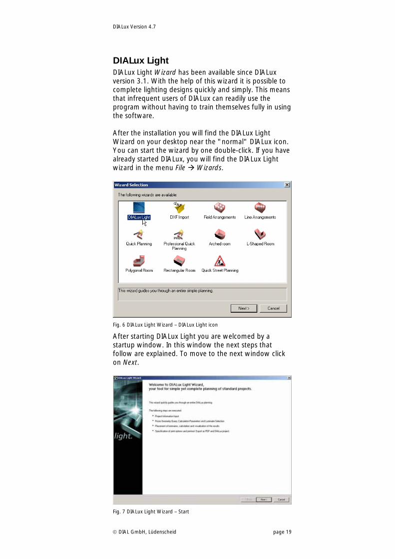
DIALux Light DIALux Light Wizard has been available since DIALux version 3.1. With the help of this wizard it is possible to complete lighting designs quickly and simply. This means that infrequent users of DIALux can readily use the program without having to train themselves fully in using the software. After the installation you will find the DIALux Light Wizard on your desktop near the "normal" DIALux icon. You can start the wizard by one double-click. If you have already started DIALux, you will find the DIALux Light wizard in the menu File Wizards.
Fig. 6 DIALux Light Wizard – DIALux Light icon
After starting DIALux Light you are welcomed by a startup window. In this window the next steps that follow are explained. To move to the next window click on Next.
Fig. 7 DIALux Light Wizard – Start
DIALux Version 4.7
DIAL GmbH, Lüdenscheid page 20
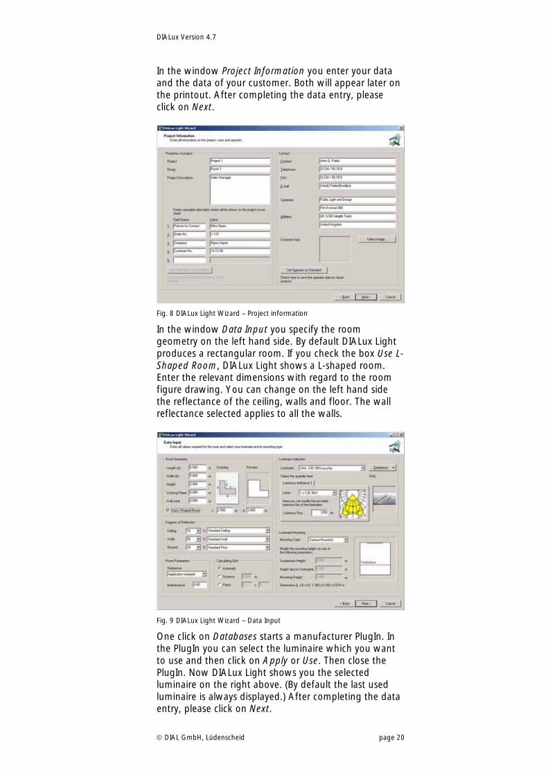
In the window Project Information you enter your data and the data of your customer. Both will appear later on the printout. After completing the data entry, please click on Next.
Fig. 8 DIALux Light Wizard – Project information
In the window Data Input you specify the room geometry on the left hand side. By default DIALux Light produces a rectangular room. If you check the box Use L-Shaped Room, DIALux Light shows a L-shaped room. Enter the relevant dimensions with regard to the room figure drawing. You can change on the left hand side the reflectance of the ceiling, walls and floor. The wall reflectance selected applies to all the walls.
Fig. 9 DIALux Light Wizard – Data Input
One click on Databases starts a manufacturer PlugIn. In the PlugIn you can select the luminaire which you want to use and then click on Apply or Use. Then close the PlugIn. Now DIALux Light shows you the selected luminaire on the right above. (By default the last used luminaire is always displayed.) After completing the data entry, please click on Next.
DIALux Version 4.7
DIAL GmbH, Lüdenscheid page 21
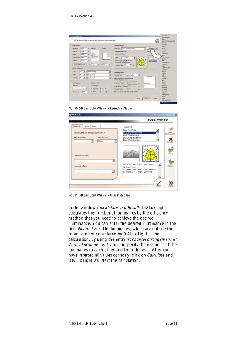
Fig. 10 DIALux Light Wizard – Launch a PlugIn
Fig. 11 DIALux Light Wizard – User Database
In the window Calculation and Results DIALux Light calculates the number of luminaires by the efficiency method that you need to achieve the desired illuminance. You can enter the desired illuminance in the field Planned Em. The luminaires, which are outside the room, are not considered by DIALux Light in the calculation. By using the entry Horizontal arrangement or Vertical arrangement you can specify the distances of the luminaires to each other and from the wall. After you have inserted all values correctly, click on Calculate and DIALux Light will start the calculation.
DIALux Version 4.7
DIAL GmbH, Lüdenscheid page 22
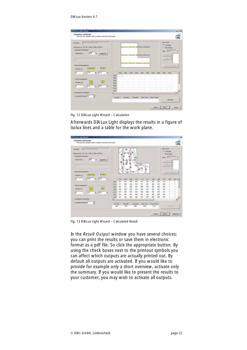
Fig. 12 DIALux Light Wizard – Calculation
Afterwards DIALux Light displays the results in a figure of isolux lines and a table for the work plane.
Fig. 13 DIALux Light Wizard – Calculated Result
In the Result Output window you have several choices; you can print the results or save them in electronic format as a pdf file. So click the appropriate button. By using the check boxes next to the printout symbols you can affect which outputs are actually printed out. By default all outputs are activated. If you would like to provide for example only a short overview, activate only the summary. If you would like to present the results to your customer, you may wish to activate all outputs.
DIALux Version 4.7
DIAL GmbH, Lüdenscheid page 23
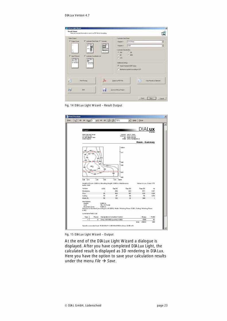
Fig. 14 DIALux Light Wizard – Result Output
Fig. 15 DIALux Light Wizard – Output
At the end of the DIALux Light Wizard a dialogue is displayed. After you have completed DIALux Light, the calculated result is displayed as 3D rendering in DIALux. Here you have the option to save your calculation results under the menu File Save.
DIALux Version 4.7
DIAL GmbH, Lüdenscheid page 24
Fig. 16 DIALux Light Wizard – End
DIALux Version 4.7
DIAL GmbH, Lüdenscheid page 25
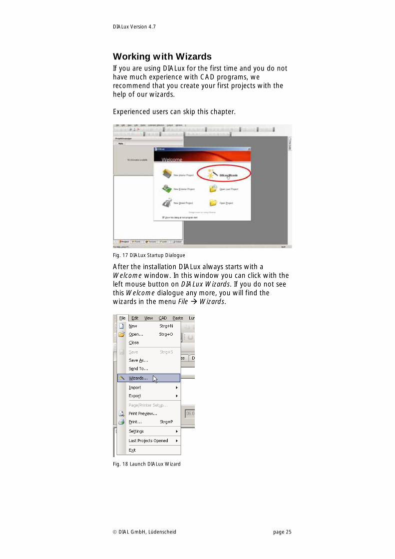
Working with Wizards If you are using DIALux for the first time and you do not have much experience with CAD programs, we recommend that you create your first projects with the help of our wizards. Experienced users can skip this chapter.
Fig. 17 DIALux Startup Dialogue
After the installation DIALux always starts with a Welcome window. In this window you can click with the left mouse button on DIALux Wizards. If you do not see this Welcome dialogue any more, you will find the wizards in the menu File Wizards.
Fig. 18 Launch DIALux Wizard
DIALux Version 4.7
DIAL GmbH, Lüdenscheid page 26
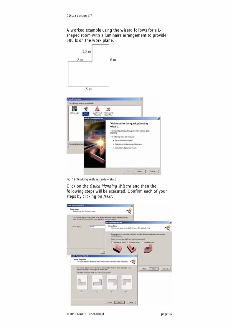
A worked example using the wizard follows for a L-shaped room with a luminaire arrangement to provide 500 lx on the work plane.
Fig. 19 Working with Wizards – Start
Click on the Quick Planning Wizard and then the following steps will be executed. Confirm each of your steps by clicking on Next.
DIALux Version 4.7
DIAL GmbH, Lüdenscheid page 27
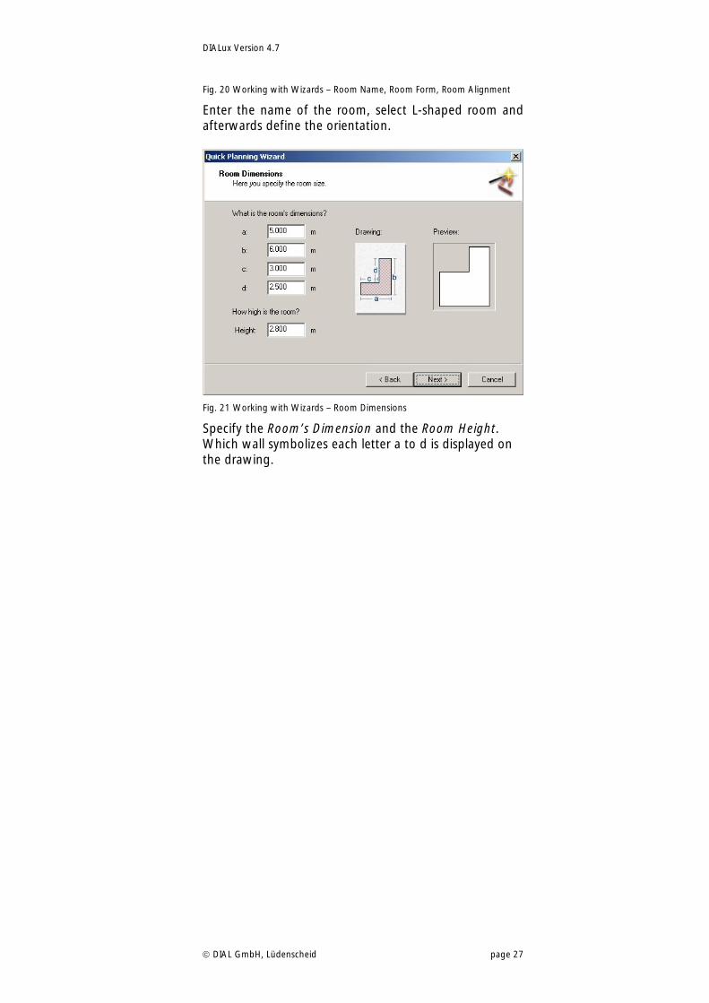
Fig. 20 Working with Wizards – Room Name, Room Form, Room Alignment
Enter the name of the room, select L-shaped room and afterwards define the orientation.
Fig. 21 Working with Wizards – Room Dimensions
Specify the Room’s Dimension and the Room Height. Which wall symbolizes each letter a to d is displayed on the drawing.
DIALux Version 4.7
DIAL GmbH, Lüdenscheid page 28
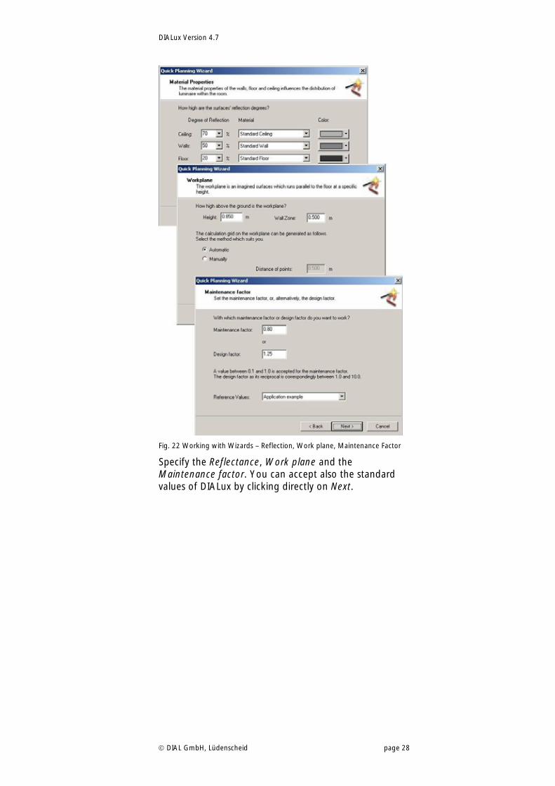
Fig. 22 Working with Wizards – Reflection, Work plane, Maintenance Factor
Specify the Reflectance, Work plane and the Maintenance factor. You can accept also the standard values of DIALux by clicking directly on Next.
DIALux Version 4.7
DIAL GmbH, Lüdenscheid page 29
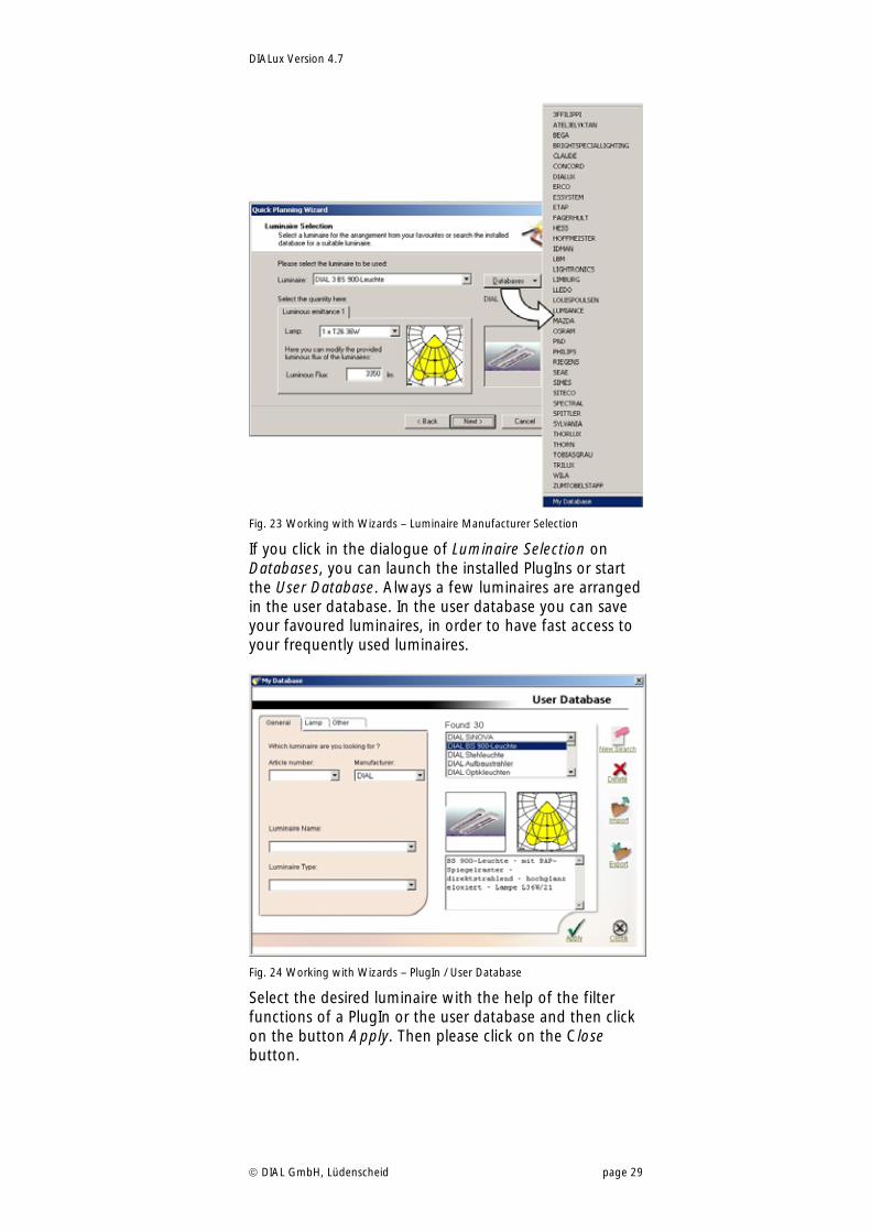
Fig. 23 Working with Wizards – Luminaire Manufacturer Selection
If you click in the dialogue of Luminaire Selection on Databases, you can launch the installed PlugIns or start the User Database. Always a few luminaires are arranged in the user database. In the user database you can save your favoured luminaires, in order to have fast access to your frequently used luminaires.
Fig. 24 Working with Wizards – PlugIn / User Database
Select the desired luminaire with the help of the filter functions of a PlugIn or the user database and then click on the button Apply. Then please click on the Close button.
DIALux Version 4.7
DIAL GmbH, Lüdenscheid page 30
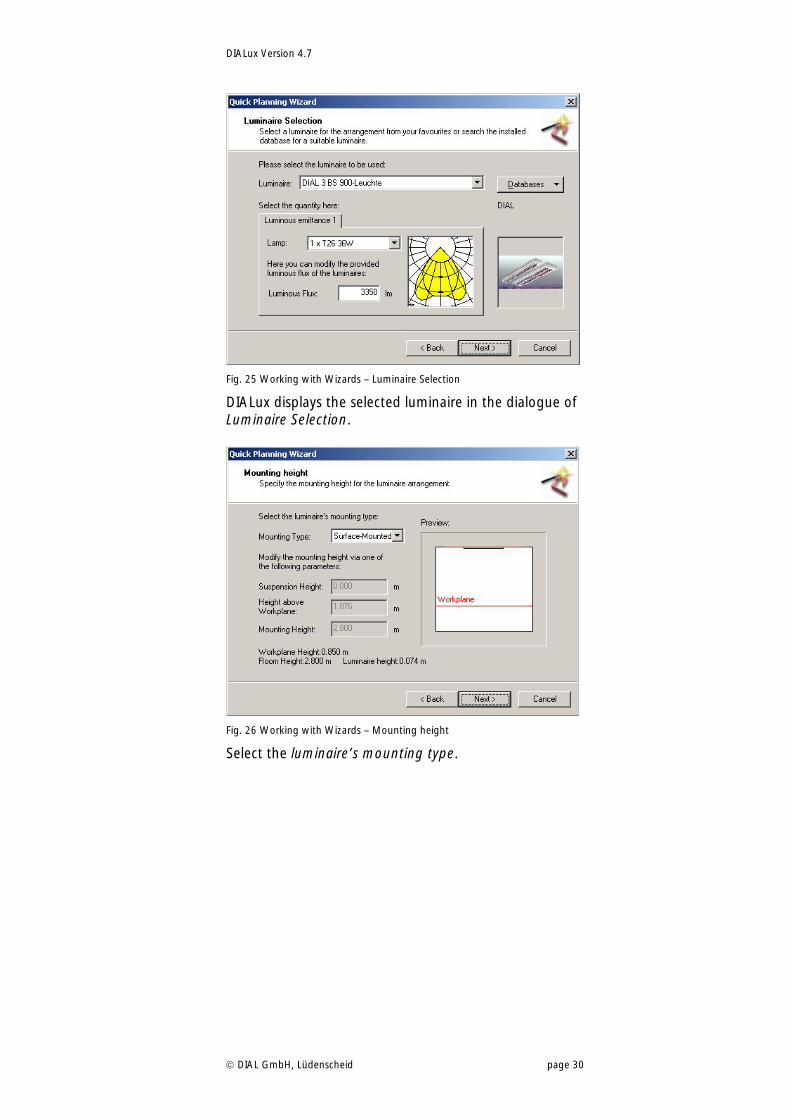
Fig. 25 Working with Wizards – Luminaire Selection
DIALux displays the selected luminaire in the dialogue of Luminaire Selection.
Fig. 26 Working with Wizards – Mounting height
Select the luminaire’s mounting type.
DIALux Version 4.7
DIAL GmbH, Lüdenscheid page 31
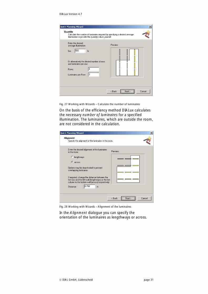
Fig. 27 Working with Wizards – Calculate the number of luminaires
On the basis of the efficiency method DIALux calculates the necessary number of luminaires for a specified illumination. The luminaires, which are outside the room, are not considered in the calculation.
Fig. 28 Working with Wizards – Alignment of the luminaires
In the Alignment dialogue you can specify the orientation of the luminaires as lengthways or across.
DIALux Version 4.7
DIAL GmbH, Lüdenscheid page 32
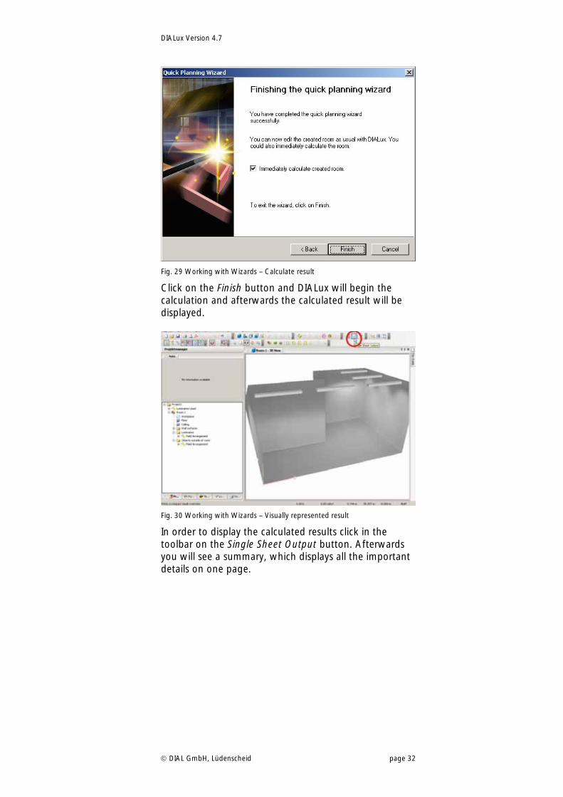
Fig. 29 Working with Wizards – Calculate result
Click on the Finish button and DIALux will begin the calculation and afterwards the calculated result will be displayed.
Fig. 30 Working with Wizards – Visually represented result
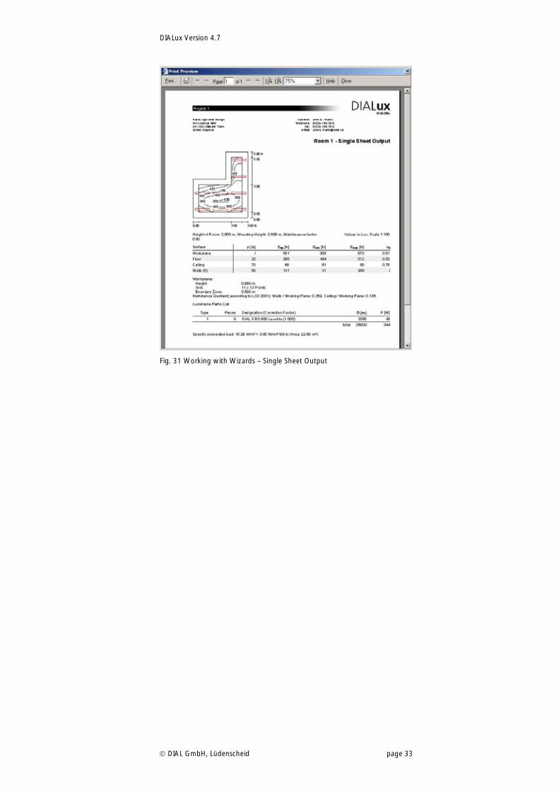
In order to display the calculated results click in the toolbar on the Single Sheet Output button. Afterwards you will see a summary, which displays all the important details on one page.
DIALux Version 4.7
DIAL GmbH, Lüdenscheid page 33
Fig. 31 Working with Wizards – Single Sheet Output
DIALux Version 4.7
DIAL GmbH, Lüdenscheid page 34
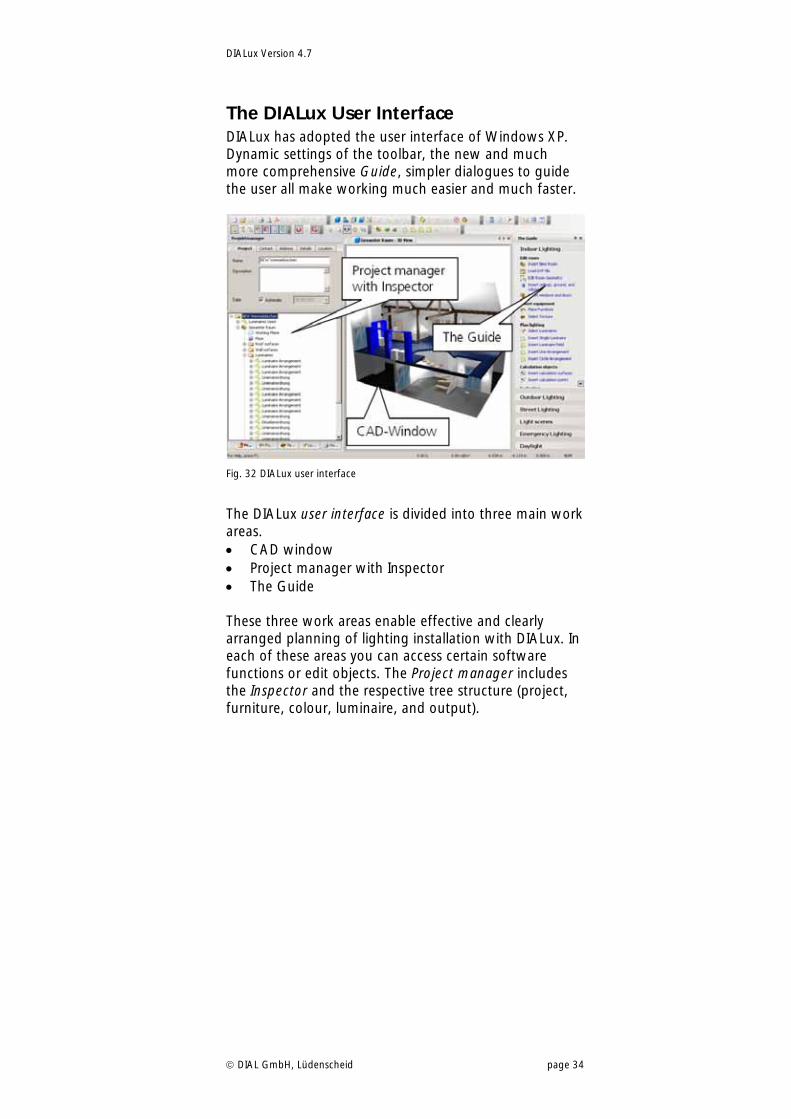
The DIALux User Interface DIALux has adopted the user interface of Windows XP. Dynamic settings of the toolbar, the new and much more comprehensive Guide, simpler dialogues to guide the user all make working much easier and much faster.
Fig. 32 DIALux user interface
The DIALux user interface is divided into three main work areas. CAD window Project manager with Inspector The Guide These three work areas enable effective and clearly arranged planning of lighting installation with DIALux. In each of these areas you can access certain software functions or edit objects. The Project manager includes the Inspector and the respective tree structure (project, furniture, colour, luminaire, and output).
DIALux Version 4.7
DIAL GmbH, Lüdenscheid page 35
The CAD Window
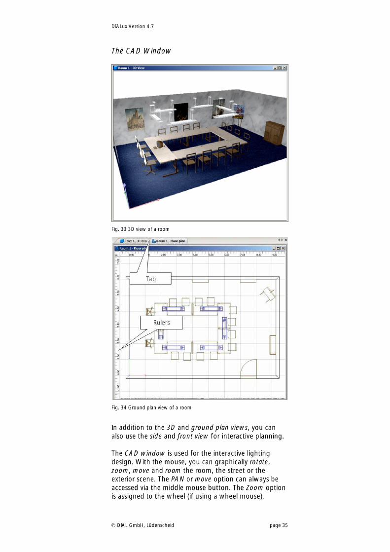
Fig. 33 3D view of a room
Fig. 34 Ground plan view of a room
In addition to the 3D and ground plan views, you can also use the side and front view for interactive planning. The CAD window is used for the interactive lighting design. With the mouse, you can graphically rotate, zoom, move and roam the room, the street or the exterior scene. The PAN or move option can always be accessed via the middle mouse button. The Zoom option is assigned to the wheel (if using a wheel mouse).
DIALux Version 4.7
DIAL GmbH, Lüdenscheid page 36
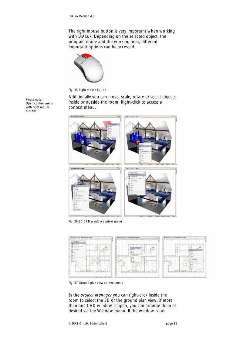
The right mouse button is very important when working with DIALux. Depending on the selected object, the program mode and the working area, different important options can be accessed.
Fig. 35 Right mouse button
Additionally you can move, scale, rotate or select objects inside or outside the room. Right-click to access a context menu.
Fig. 36 3D CAD window context menu
Fig. 37 Ground plan view context menu
In the project manager you can right-click inside the room to select the 3D or the ground plan view. If more than one CAD window is open, you can arrange them as desired via the Window menu. If the window is full
Please note: Open context menu with right mouse button!
DIALux Version 4.7
DIAL GmbH, Lüdenscheid page 37
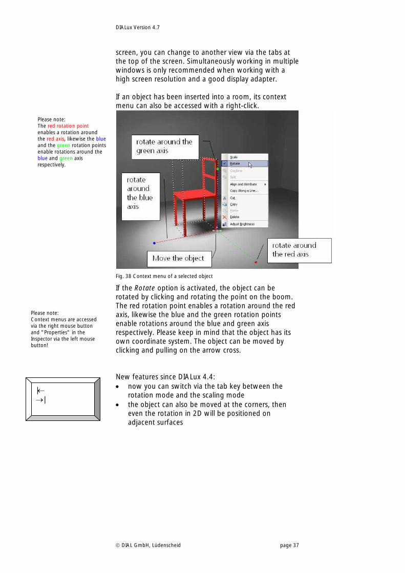
screen, you can change to another view via the tabs at the top of the screen. Simultaneously working in multiple windows is only recommended when working with a high screen resolution and a good display adapter. If an object has been inserted into a room, its context menu can also be accessed with a right-click.
Fig. 38 Context menu of a selected object
If the Rotate option is activated, the object can be rotated by clicking and rotating the point on the boom. The red rotation point enables a rotation around the red axis, likewise the blue and the green rotation points enable rotations around the blue and green axis respectively. Please keep in mind that the object has its own coordinate system. The object can be moved by clicking and pulling on the arrow cross. New features since DIALux 4.4: now you can switch via the tab key between the
rotation mode and the scaling mode the object can also be moved at the corners, then
even the rotation in 2D will be positioned on adjacent surfaces
Please note: Context menus are accessed via the right mouse button and "Properties" in the Inspector via the left mouse button!
Please note: The red rotation point enables a rotation around the red axis, likewise the blue and the green rotation points enable rotations around the blue and green axis respectively.
| |
DIALux Version 4.7
DIAL GmbH, Lüdenscheid page 38
The Project manager
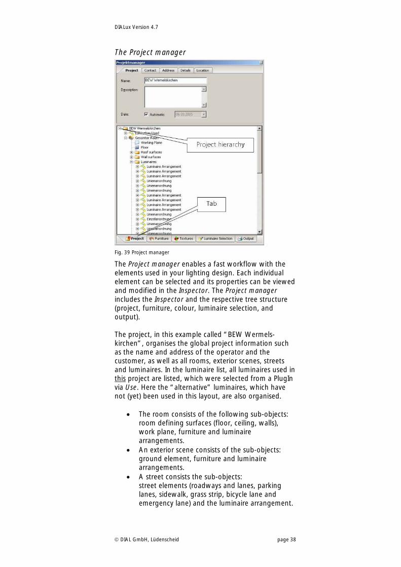
Fig. 39 Project manager
The Project manager enables a fast workflow with the elements used in your lighting design. Each individual element can be selected and its properties can be viewed and modified in the Inspector. The Project manager includes the Inspector and the respective tree structure (project, furniture, colour, luminaire selection, and output). The project, in this example called “BEW Wermels-kirchen”, organises the global project information such as the name and address of the operator and the customer, as well as all rooms, exterior scenes, streets and luminaires. In the luminaire list, all luminaires used in this project are listed, which were selected from a PlugIn via Use. Here the “alternative” luminaires, which have not (yet) been used in this layout, are also organised.
The room consists of the following sub-objects: room defining surfaces (floor, ceiling, walls), work plane, furniture and luminaire arrangements.
An exterior scene consists of the sub-objects: ground element, furniture and luminaire arrangements.
A street consists the sub-objects: street elements (roadways and lanes, parking lanes, sidewalk, grass strip, bicycle lane and emergency lane) and the luminaire arrangement.
DIALux Version 4.7
DIAL GmbH, Lüdenscheid page 39
If you select one of these elements (left-click), its properties are displayed in the Inspector. A right-click opens the context menu for that object, just as it does in the CAD view.
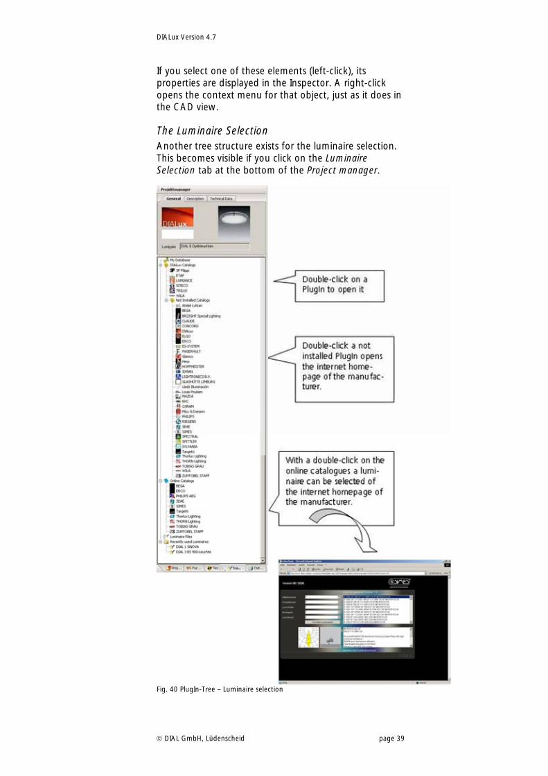
The Luminaire Selection Another tree structure exists for the luminaire selection. This becomes visible if you click on the Luminaire Selection tab at the bottom of the Project manager.
Fig. 40 PlugIn-Tree – Luminaire selection
DIALux Version 4.7
DIAL GmbH, Lüdenscheid page 40
Installed PlugIns are automatically recognized by DIALux 4.7. It is not required to reinstall the PlugIns after updating from older DIALux versions. Double-click on a PlugIn to open it. You can also access this option via the Luminaire Selection menu. PlugIns provided by our partners that have not yet been installed are located a bit lower in the tree structure. A double-click on a PlugIn which has not been installed opens the Internet Explorer window and the homepage of the luminaire manufacturer is displayed, if available. Some manufacturers provide individual luminaires or entire PlugIns for downloading here.
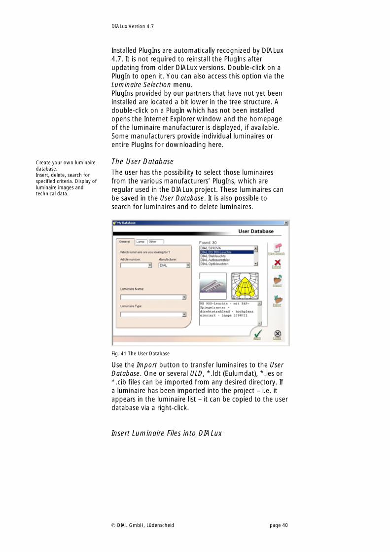
The User Database The user has the possibility to select those luminaires from the various manufacturers’ PlugIns, which are regular used in the DIALux project. These luminaires can be saved in the User Database. It is also possible to search for luminaires and to delete luminaires.
Fig. 41 The User Database
Use the Import button to transfer luminaires to the User Database. One or several ULD, *.ldt (Eulumdat), *.ies or *.cib files can be imported from any desired directory. If a luminaire has been imported into the project – i.e. it appears in the luminaire list – it can be copied to the user database via a right-click.
Insert Luminaire Files into DIALux
Create your own luminaire database. Insert, delete, search for specified criteria. Display of luminaire images and technical data.
DIALux Version 4.7
DIAL GmbH, Lüdenscheid page 41
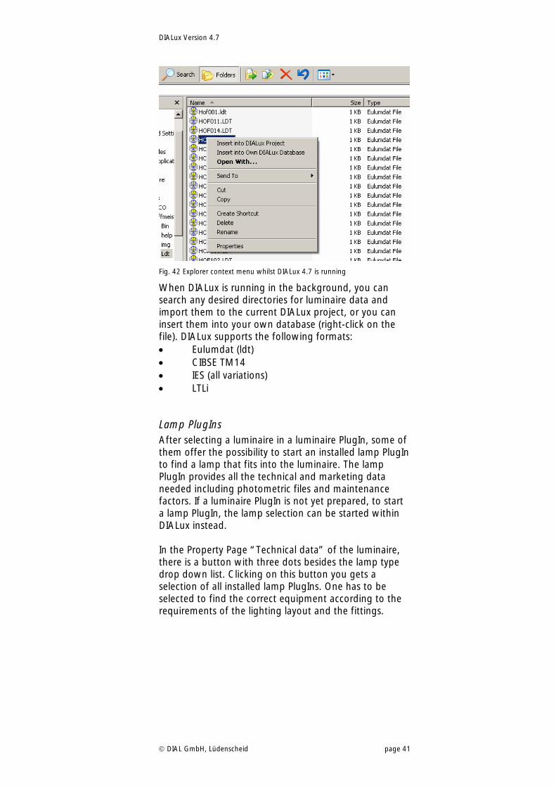
Fig. 42 Explorer context menu whilst DIALux 4.7 is running
When DIALux is running in the background, you can search any desired directories for luminaire data and import them to the current DIALux project, or you can insert them into your own database (right-click on the file). DIALux supports the following formats: Eulumdat (ldt) CIBSE TM14 IES (all variations) LTLi
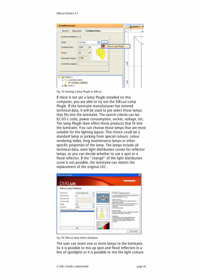
Lamp PlugIns After selecting a luminaire in a luminaire PlugIn, some of them offer the possibility to start an installed lamp PlugIn to find a lamp that fits into the luminaire. The lamp PlugIn provides all the technical and marketing data needed including photometric files and maintenance factors. If a luminaire PlugIn is not yet prepared, to start a lamp PlugIn, the lamp selection can be started within DIALux instead. In the Property Page “Technical data” of the luminaire, there is a button with three dots besides the lamp type drop down list. Clicking on this button you gets a selection of all installed lamp PlugIns. One has to be selected to find the correct equipment according to the requirements of the lighting layout and the fittings.
DIALux Version 4.7
DIAL GmbH, Lüdenscheid page 42
Fig. 43 Starting a lamp PlugIn in DIALux
If there is not yet a lamp PlugIn installed on this computer, you are able to try out the DIALux Lamp PlugIn. If the luminaire manufacturer has entered technical data, it will be used to pre select those lamps that fits into the luminaire. The search criteria can be: ILCOS-L code, power consumption, socket, voltage, etc. The lamp PlugIn then offers those products that fit into the luminaire. You can choose those lamps that are most suitable for the lighting layout. This choice could be a standard lamp or picking from special colours, colour rendering index, long maintenance lamps or other specific properties of the lamp. The lamps include all technical data, even light distribution curves for reflector lamps, so you can decide whether to use a spot or a flood reflector. If the “change” of the light distribution curve is not possible, the luminaire can restrict the replacement of the original LDC.
Fig. 44 DIALux lamp demo database
The user can insert one or more lamps to the luminaire. So it is possible to mix up spot and flood reflectors in a line of spotlights or it is possible to mix the light colours
DIALux Version 4.7
DIAL GmbH, Lüdenscheid page 43
within the some arrangement. The selected lamp can be added to the original equipment or it can replace it.
DIALux Version 4.7
DIAL GmbH, Lüdenscheid page 44
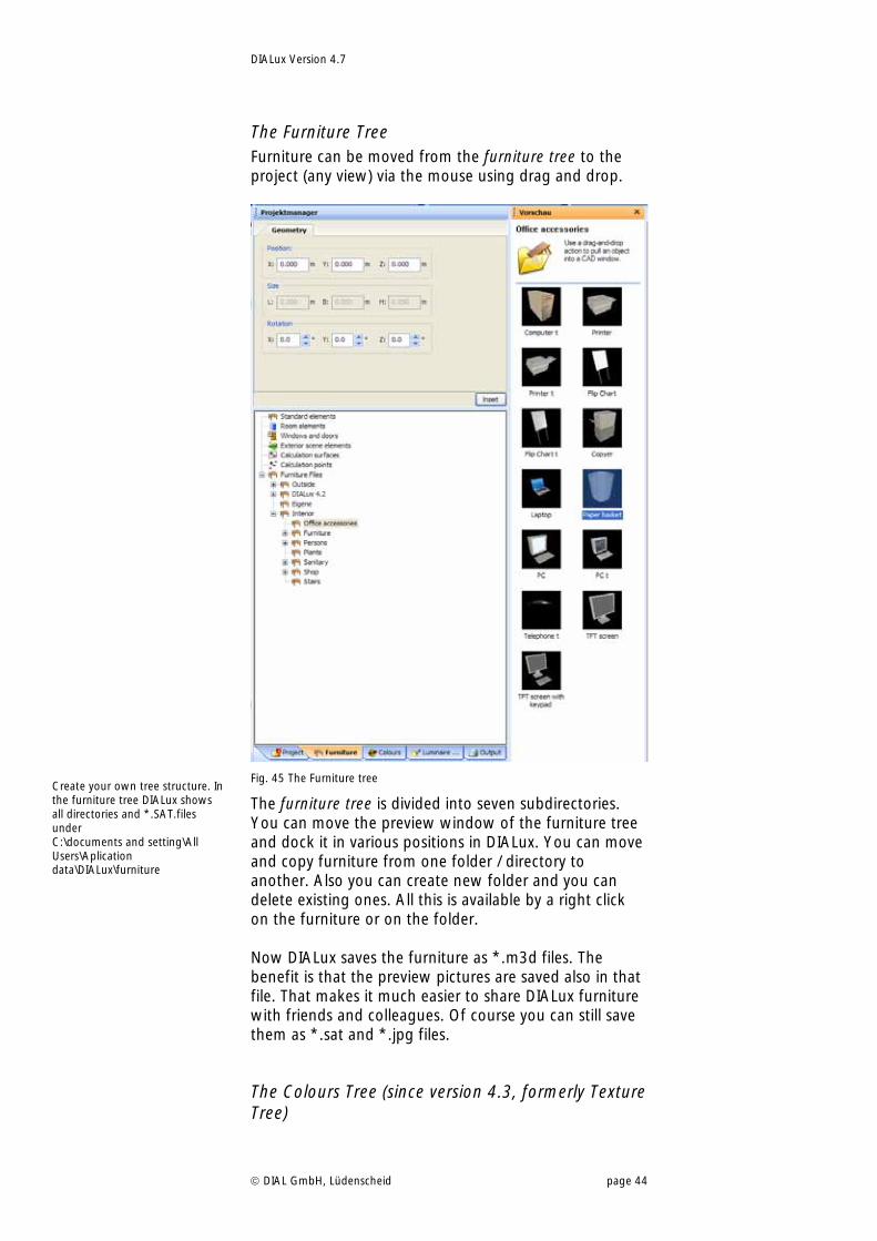
The Furniture Tree Furniture can be moved from the furniture tree to the project (any view) via the mouse using drag and drop.
Fig. 45 The Furniture tree
The furniture tree is divided into seven subdirectories. You can move the preview window of the furniture tree and dock it in various positions in DIALux. You can move and copy furniture from one folder / directory to another. Also you can create new folder and you can delete existing ones. All this is available by a right click on the furniture or on the folder. Now DIALux saves the furniture as *.m3d files. The benefit is that the preview pictures are saved also in that file. That makes it much easier to share DIALux furniture with friends and colleagues. Of course you can still save them as *.sat and *.jpg files.
The Colours Tree (since version 4.3, formerly Texture Tree)
Create your own tree structure. In the furniture tree DIALux shows all directories and *.SAT.files under C:\documents and setting\All Users\Aplication data\DIALux\furniture
DIALux Version 4.7
DIAL GmbH, Lüdenscheid page 45
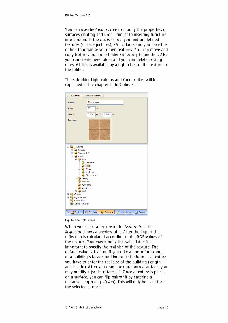
You can use the Colours tree to modify the properties of surfaces via drag and drop - similar to inserting furniture into a room. In the textures tree you find predefined textures (surface pictures), RAL colours and you have the option to organise your own textures. You can move and copy textures from one folder / directory to another. Also you can create new folder and you can delete existing ones. All this is available by a right click on the texture or the folder. The subfolder Light colours and Colour filter will be explained in the chapter Light Colours.
Fig. 46 The Colour tree
When you select a texture in the texture tree, the Inspector shows a preview of it. After the import the reflection is calculated according to the RGB-values of the texture. You may modify this value later. It is important to specify the real size of the texture. The default value is 1 x 1 m. If you take a photo for example of a building’s facade and import this photo as a texture, you have to enter the real size of the building (length and height). After you drag a texture onto a surface, you may modify it (scale, rotate,…). Once a texture is placed on a surface, you can flip /mirror it by entering a negative length (e.g. -0.4m). This will only be used for the selected surface.
DIALux Version 4.7
DIAL GmbH, Lüdenscheid page 46
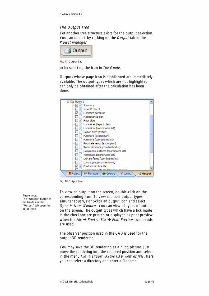
The Output Tree Yet another tree structure exists for the output selection. You can open it by clicking on the Output tab in the Project manager
Fig. 47 Output Tab
or by selecting the icon in The Guide. Outputs whose page icon is highlighted are immediately available. The output types which are not highlighted can only be obtained after the calculation has been done.
Fig. 48 Output tree
To view an output on the screen, double-click on the corresponding icon. To view multiple output types simultaneously, right-click an output icon and select Open in New Window. You can view all types of output on the screen. The output types which have a tick made in the checkbox are printed or displayed as print preview when the File Print or File Print Preview commands are used. The observer position used in the CAD is used for the output 3D rendering. You may save the 3D rendering as a *.jpg picture. Just move the rendering into the required position and select in the menu File Export Save CAD view as JPG. Here you can select a directory and enter a filename.
Please note: The “Output” button in the Guide and the “Output” tab open the output tree
DIALux Version 4.7
DIAL GmbH, Lüdenscheid page 47
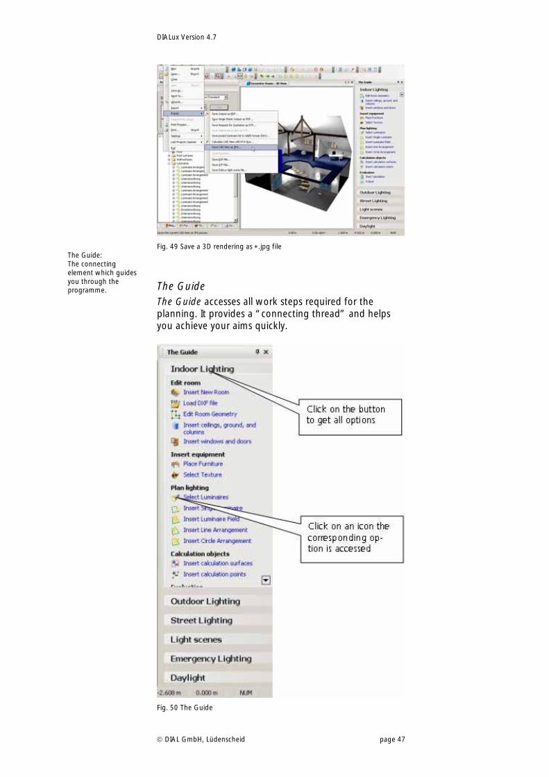
Fig. 49 Save a 3D rendering as .jpg file
The Guide The Guide accesses all work steps required for the planning. It provides a “connecting thread” and helps you achieve your aims quickly.
Fig. 50 The Guide
The Guide: The connecting element which guides you through the programme.
DIALux Version 4.7
DIAL GmbH, Lüdenscheid page 48
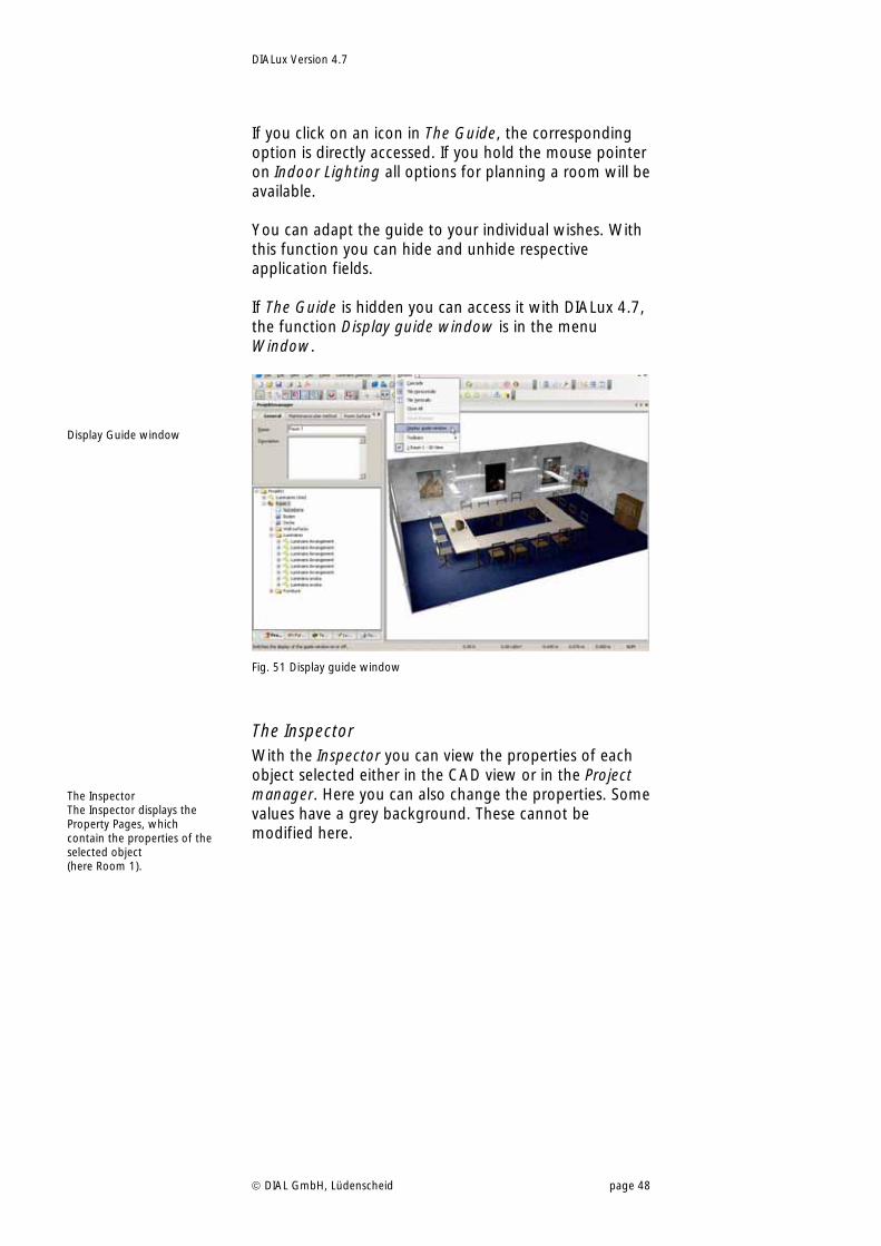
If you click on an icon in The Guide, the corresponding option is directly accessed. If you hold the mouse pointer on Indoor Lighting all options for planning a room will be available. You can adapt the guide to your individual wishes. With this function you can hide and unhide respective application fields. If The Guide is hidden you can access it with DIALux 4.7, the function Display guide window is in the menu Window.
Fig. 51 Display guide window
The Inspector With the Inspector you can view the properties of each object selected either in the CAD view or in the Project manager. Here you can also change the properties. Some values have a grey background. These cannot be modified here.
The Inspector The Inspector displays the Property Pages, which contain the properties of the selected object (here Room 1).
Display Guide window
DIALux Version 4.7
DIAL GmbH, Lüdenscheid page 49
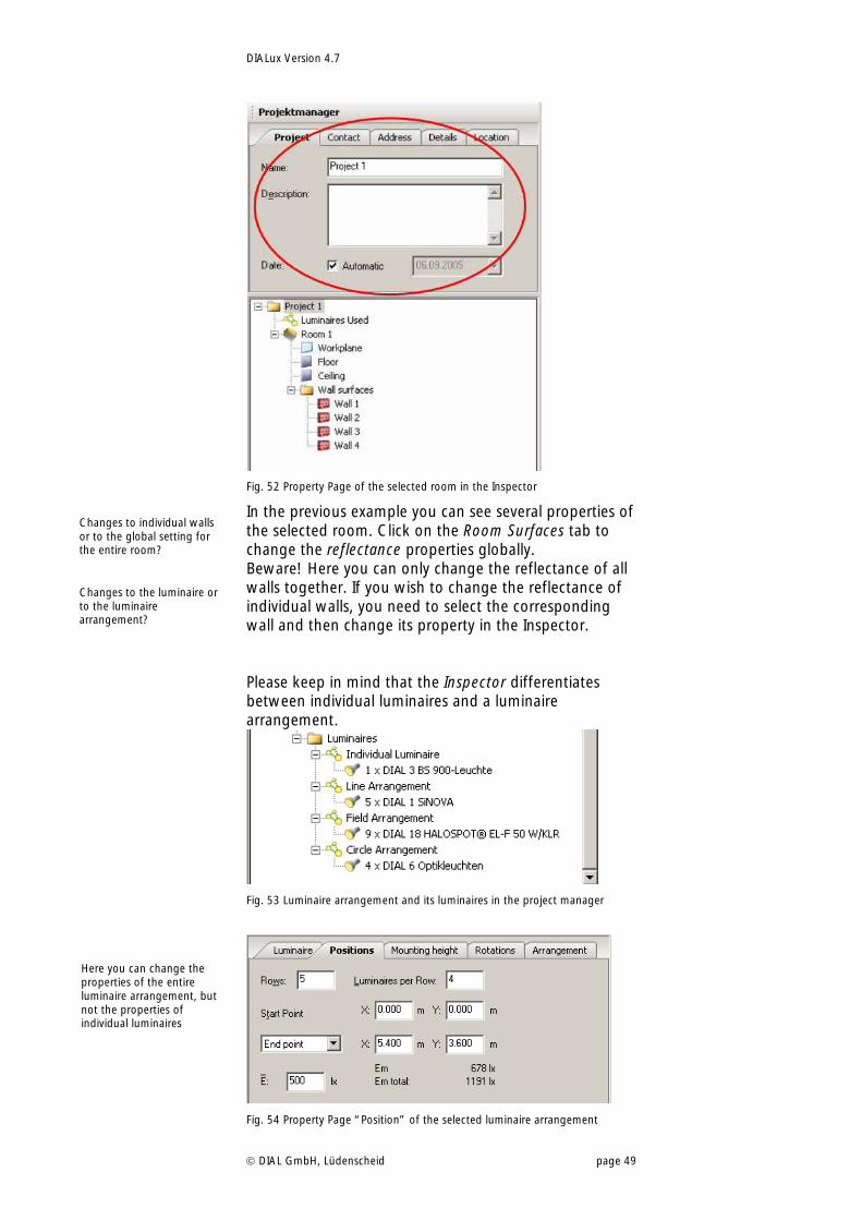
Fig. 52 Property Page of the selected room in the Inspector
In the previous example you can see several properties of the selected room. Click on the Room Surfaces tab to change the reflectance properties globally. Beware! Here you can only change the reflectance of all walls together. If you wish to change the reflectance of individual walls, you need to select the corresponding wall and then change its property in the Inspector. Please keep in mind that the Inspector differentiates between individual luminaires and a luminaire arrangement.
Fig. 53 Luminaire arrangement and its luminaires in the project manager
Fig. 54 Property Page “Position” of the selected luminaire arrangement
Changes to individual walls or to the global setting for the entire room?
Changes to the luminaire or to the luminaire arrangement?
Here you can change the properties of the entire luminaire arrangement, but not the properties of individual luminaires
DIALux Version 4.7
DIAL GmbH, Lüdenscheid page 50
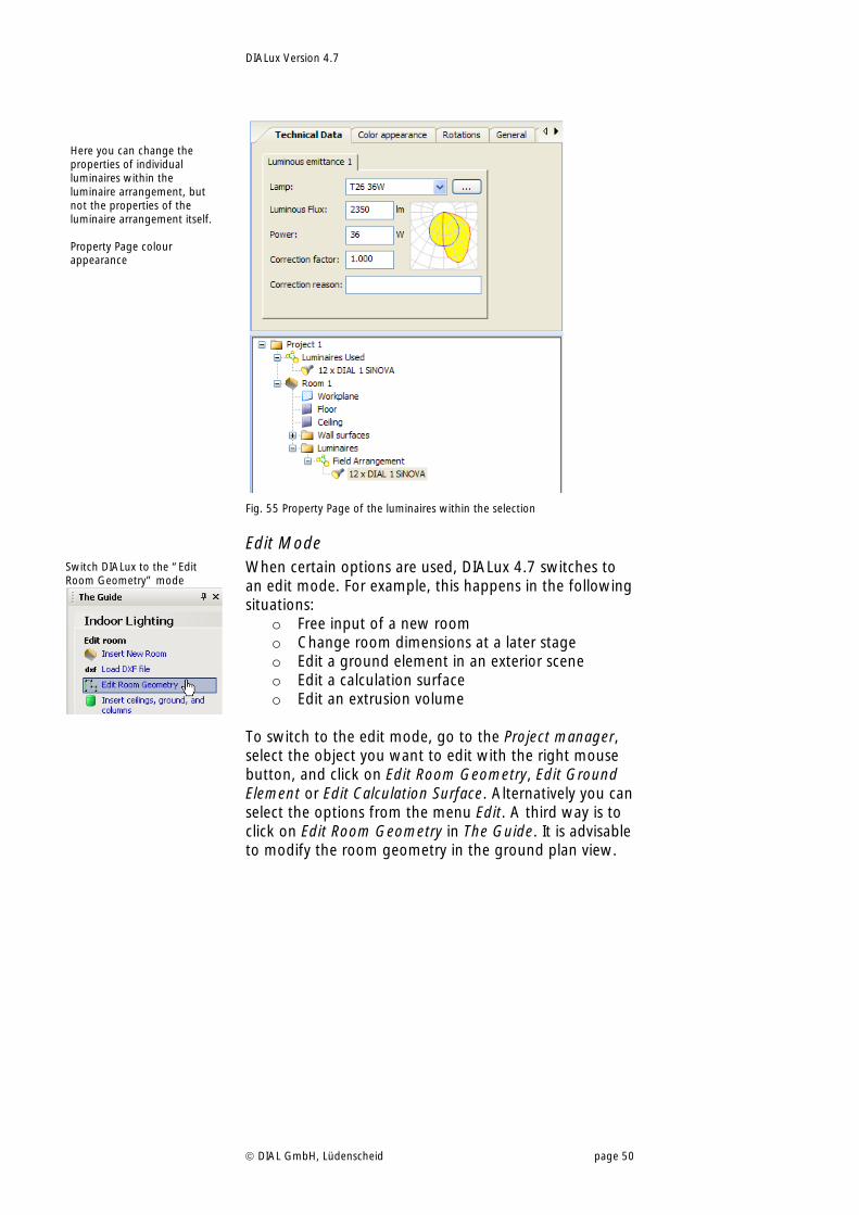
Fig. 55 Property Page of the luminaires within the selection
Edit Mode When certain options are used, DIALux 4.7 switches to an edit mode. For example, this happens in the following situations:
o Free input of a new room o Change room dimensions at a later stage o Edit a ground element in an exterior scene o Edit a calculation surface o Edit an extrusion volume
To switch to the edit mode, go to the Project manager, select the object you want to edit with the right mouse button, and click on Edit Room Geometry, Edit Ground Element or Edit Calculation Surface. Alternatively you can select the options from the menu Edit. A third way is to click on Edit Room Geometry in The Guide. It is advisable to modify the room geometry in the ground plan view.
Switch DIALux to the “Edit Room Geometry” mode
Here you can change the properties of individual luminaires within the luminaire arrangement, but not the properties of the luminaire arrangement itself. Property Page colour appearance
DIALux Version 4.7
DIAL GmbH, Lüdenscheid page 51
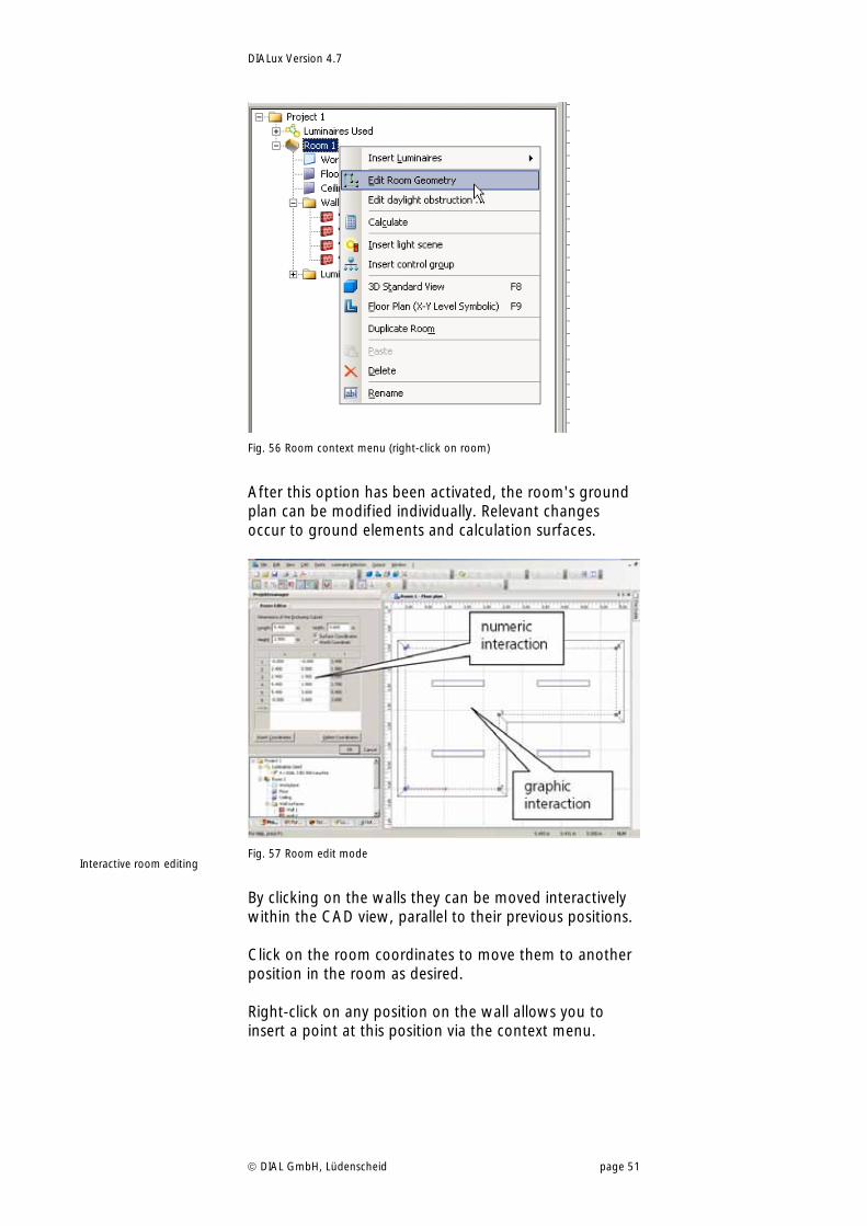
Fig. 56 Room context menu (right-click on room)
After this option has been activated, the room's ground plan can be modified individually. Relevant changes occur to ground elements and calculation surfaces.
Fig. 57 Room edit mode
By clicking on the walls they can be moved interactively within the CAD view, parallel to their previous positions. Click on the room coordinates to move them to another position in the room as desired. Right-click on any position on the wall allows you to insert a point at this position via the context menu.
Interactive room editing
DIALux Version 4.7
DIAL GmbH, Lüdenscheid page 52
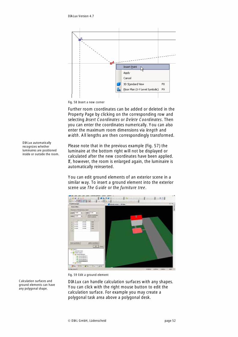
Fig. 58 Insert a new corner
Further room coordinates can be added or deleted in the Property Page by clicking on the corresponding row and selecting Insert Coordinates or Delete Coordinates. Then you can enter the coordinates numerically. You can also enter the maximum room dimensions via length and width. All lengths are then correspondingly transformed. Please note that in the previous example (Fig. 57) the luminaire at the bottom right will not be displayed or calculated after the new coordinates have been applied. If, however, the room is enlarged again, the luminaire is automatically reinserted. You can edit ground elements of an exterior scene in a similar way. To insert a ground element into the exterior scene use The Guide or the furniture tree.
Fig. 59 Edit a ground element
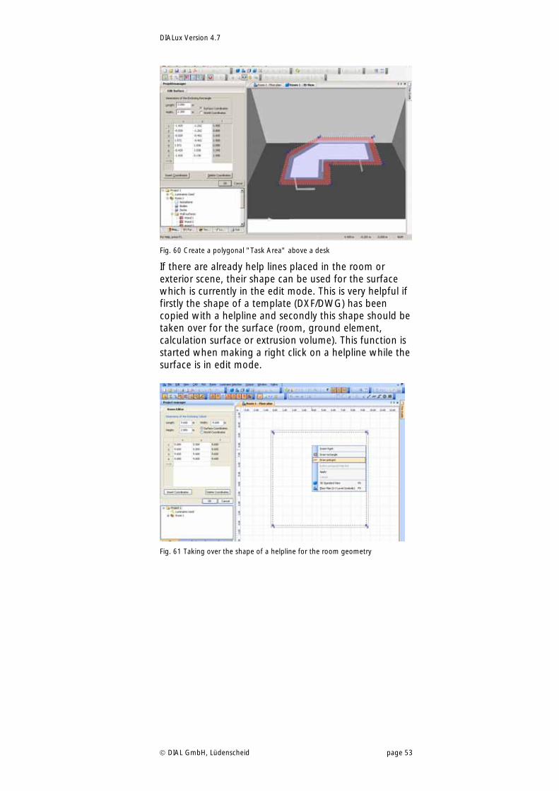
DIALux can handle calculation surfaces with any shapes. You can click with the right mouse button to edit the calculation surface. For example you may create a polygonal task area above a polygonal desk.
DIALux automatically recognizes whether luminaires are positioned inside or outside the room.
Calculation surfaces and ground elements can have any polygonal shape.
DIALux Version 4.7
DIAL GmbH, Lüdenscheid page 53
Fig. 60 Create a polygonal "Task Area" above a desk
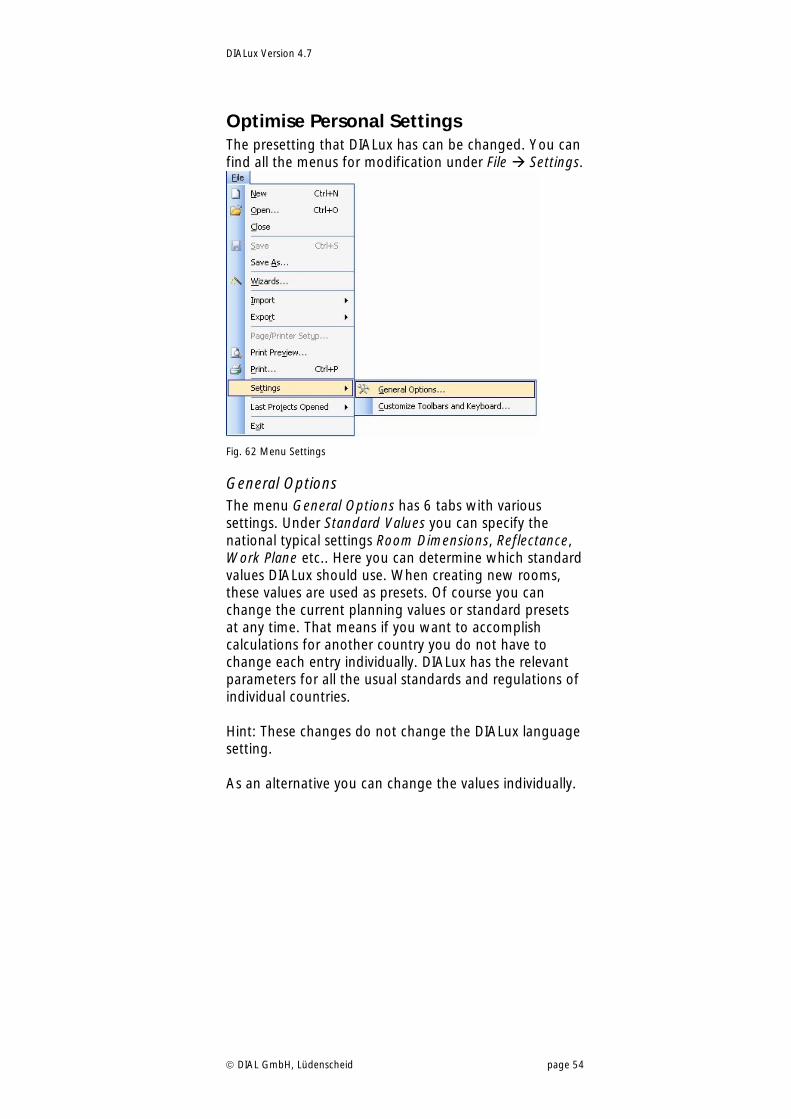
If there are already help lines placed in the room or exterior scene, their shape can be used for the surface which is currently in the edit mode. This is very helpful if firstly the shape of a template (DXF/DWG) has been copied with a helpline and secondly this shape should be taken over for the surface (room, ground element, calculation surface or extrusion volume). This function is started when making a right click on a helpline while the surface is in edit mode.
Fig. 61 Taking over the shape of a helpline for the room geometry
DIALux Version 4.7
DIAL GmbH, Lüdenscheid page 54
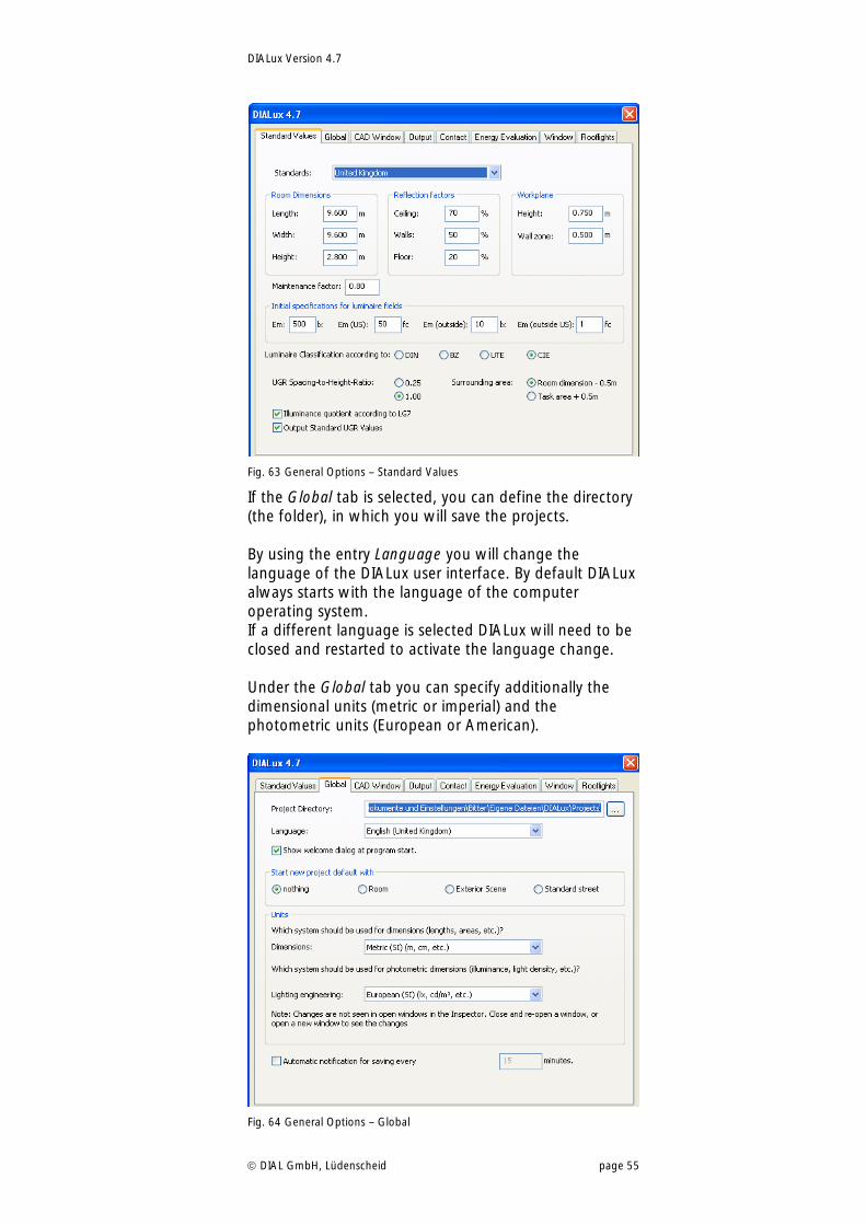
Optimise Personal Settings The presetting that DIALux has can be changed. You can find all the menus for modification under File Settings.
Fig. 62 Menu Settings
General Options The menu General Options has 6 tabs with various settings. Under Standard Values you can specify the national typical settings Room Dimensions, Reflectance, Work Plane etc.. Here you can determine which standard values DIALux should use. When creating new rooms, these values are used as presets. Of course you can change the current planning values or standard presets at any time. That means if you want to accomplish calculations for another country you do not have to change each entry individually. DIALux has the relevant parameters for all the usual standards and regulations of individual countries. Hint: These changes do not change the DIALux language setting. As an alternative you can change the values individually.
DIALux Version 4.7
DIAL GmbH, Lüdenscheid page 55
Fig. 63 General Options – Standard Values
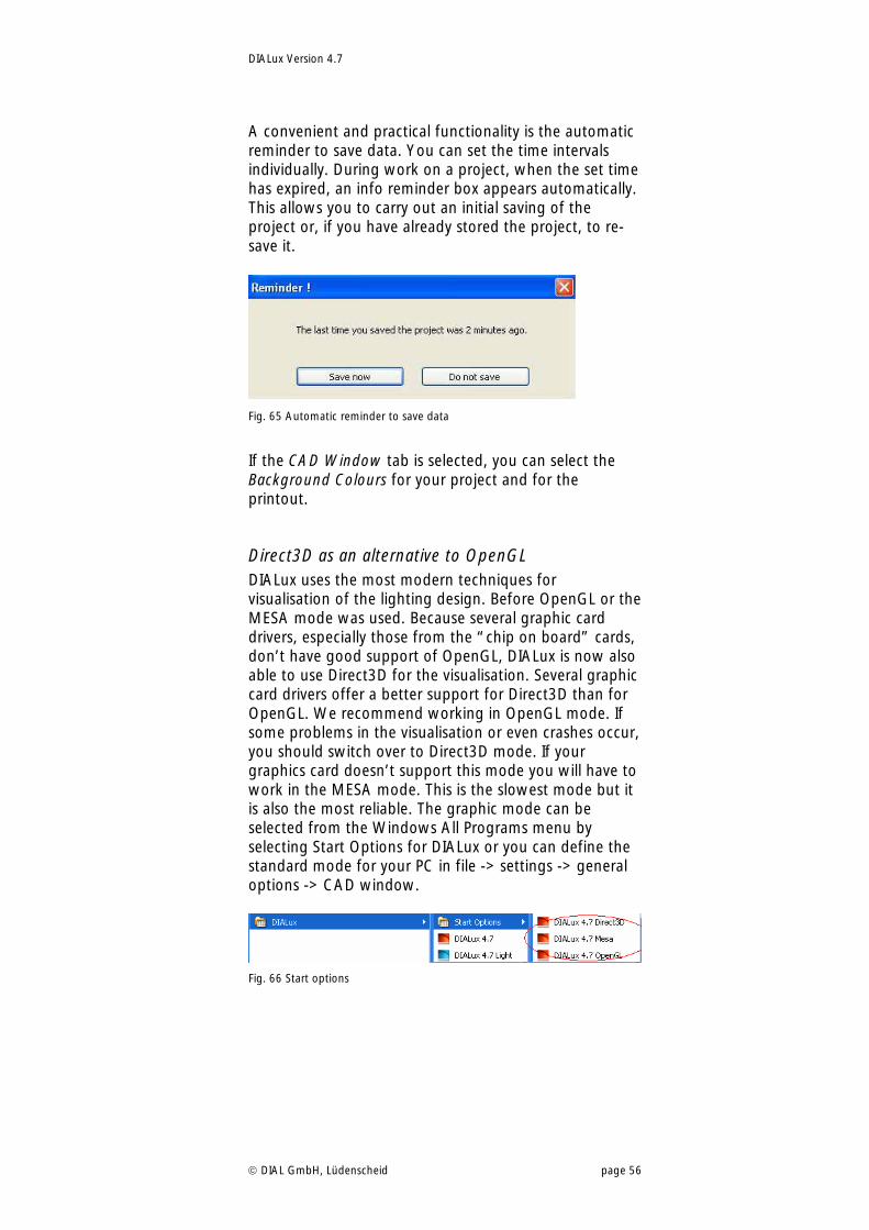
If the Global tab is selected, you can define the directory (the folder), in which you will save the projects. By using the entry Language you will change the language of the DIALux user interface. By default DIALux always starts with the language of the computer operating system. If a different language is selected DIALux will need to be closed and restarted to activate the language change. Under the Global tab you can specify additionally the dimensional units (metric or imperial) and the photometric units (European or American).
Fig. 64 General Options – Global
DIALux Version 4.7
DIAL GmbH, Lüdenscheid page 56
A convenient and practical functionality is the automatic reminder to save data. You can set the time intervals individually. During work on a project, when the set time has expired, an info reminder box appears automatically. This allows you to carry out an initial saving of the project or, if you have already stored the project, to re-save it.
Fig. 65 Automatic reminder to save data
If the CAD Window tab is selected, you can select the Background Colours for your project and for the printout.
Direct3D as an alternative to OpenGL DIALux uses the most modern techniques for visualisation of the lighting design. Before OpenGL or the MESA mode was used. Because several graphic card drivers, especially those from the “chip on board” cards, don’t have good support of OpenGL, DIALux is now also able to use Direct3D for the visualisation. Several graphic card drivers offer a better support for Direct3D than for OpenGL. We recommend working in OpenGL mode. If some problems in the visualisation or even crashes occur, you should switch over to Direct3D mode. If your graphics card doesn’t support this mode you will have to work in the MESA mode. This is the slowest mode but it is also the most reliable. The graphic mode can be selected from the Windows All Programs menu by selecting Start Options for DIALux or you can define the standard mode for your PC in file -> settings -> general options -> CAD window.
Fig. 66 Start options
DIALux Version 4.7
DIAL GmbH, Lüdenscheid page 57
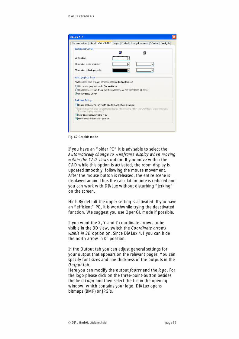
Fig. 67 Graphic mode
If you have an “older PC” it is advisable to select the Automatically change to wireframe display when moving within the CAD views option. If you move within the CAD while this option is activated, the room display is updated smoothly, following the mouse movement. After the mouse button is released, the entire scene is displayed again. Thus the calculation time is reduced and you can work with DIALux without disturbing “jerking” on the screen. Hint: By default the upper setting is activated. If you have an “efficient” PC, it is worthwhile trying the deactivated function. We suggest you use OpenGL mode if possible. If you want the X, Y and Z coordinate arrows to be visible in the 3D view, switch the Coordinate arrows visible in 3D option on. Since DIALux 4.1 you can hide the north arrow in 0° position. In the Output tab you can adjust general settings for your output that appears on the relevant pages. You can specify font sizes and line thickness of the outputs in the Output tab. Here you can modify the output footer and the logo. For the logo please click on the three-point-button besides the field Logo and then select the file in the opening window, which contains your logo. DIALux opens bitmaps (BMP) or JPG’s.
DIALux Version 4.7
DIAL GmbH, Lüdenscheid page 58
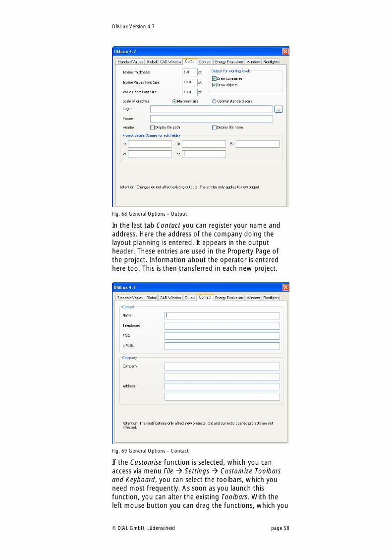
Fig. 68 General Options – Output
In the last tab Contact you can register your name and address. Here the address of the company doing the layout planning is entered. It appears in the output header. These entries are used in the Property Page of the project. Information about the operator is entered here too. This is then transferred in each new project.
Fig. 69 General Options – Contact
If the Customise function is selected, which you can access via menu File Settings Customize Toolbars and Keyboard, you can select the toolbars, which you need most frequently. As soon as you launch this function, you can alter the existing Toolbars. With the left mouse button you can drag the functions, which you
DIALux Version 4.7
DIAL GmbH, Lüdenscheid page 59
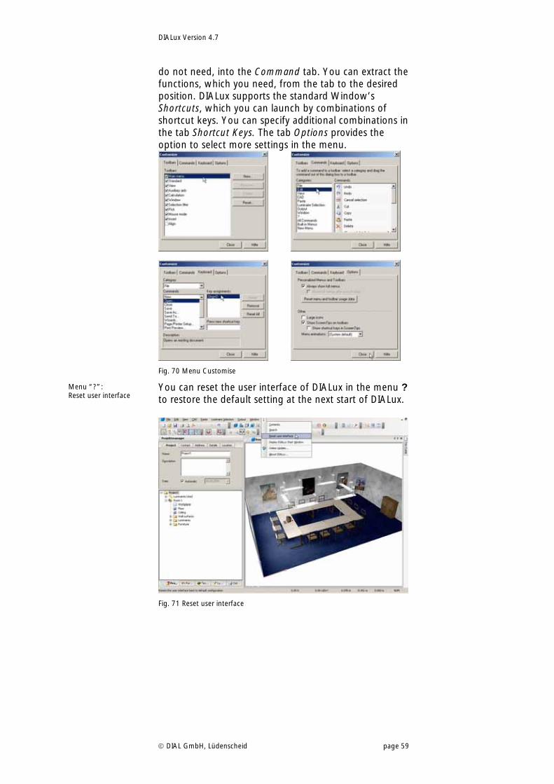
do not need, into the Command tab. You can extract the functions, which you need, from the tab to the desired position. DIALux supports the standard Window’s Shortcuts, which you can launch by combinations of shortcut keys. You can specify additional combinations in the tab Shortcut Keys. The tab Options provides the option to select more settings in the menu.
Fig. 70 Menu Customise
You can reset the user interface of DIALux in the menu ? to restore the default setting at the next start of DIALux.
Fig. 71 Reset user interface
Menu “?”: Reset user interface
DIALux Version 4.7
DIAL GmbH, Lüdenscheid page 60
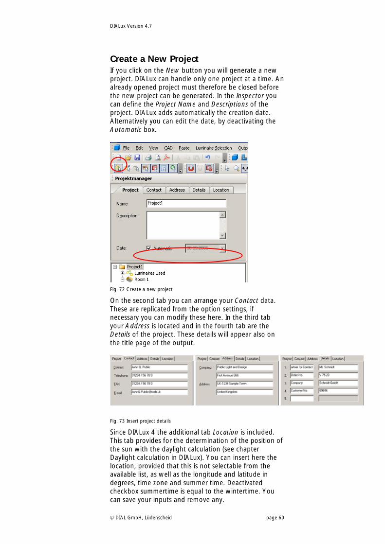
Create a New Project If you click on the New button you will generate a new project. DIALux can handle only one project at a time. An already opened project must therefore be closed before the new project can be generated. In the Inspector you can define the Project Name and Descriptions of the project. DIALux adds automatically the creation date. Alternatively you can edit the date, by deactivating the Automatic box.
Fig. 72 Create a new project
On the second tab you can arrange your Contact data. These are replicated from the option settings, if necessary you can modify these here. In the third tab your Address is located and in the fourth tab are the Details of the project. These details will appear also on the title page of the output.
Fig. 73 Insert project details
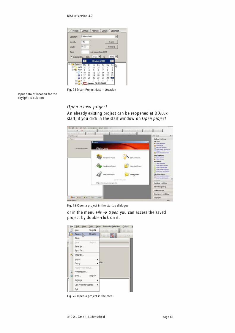
Since DIALux 4 the additional tab Location is included. This tab provides for the determination of the position of the sun with the daylight calculation (see chapter Daylight calculation in DIALux). You can insert here the location, provided that this is not selectable from the available list, as well as the longitude and latitude in degrees, time zone and summer time. Deactivated checkbox summertime is equal to the wintertime. You can save your inputs and remove any.
DIALux Version 4.7
DIAL GmbH, Lüdenscheid page 61
Fig. 74 Insert Project data – Location
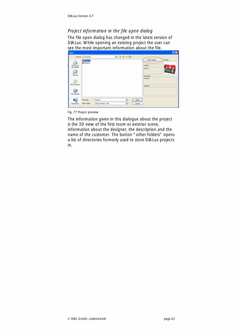
Open a new project An already existing project can be reopened at DIALux start, if you click in the start window on Open project
Fig. 75 Open a project in the startup dialogue
or in the menu File Open you can access the saved project by double-click on it.
Fig. 76 Open a project in the menu
Input data of location for the daylight calculation
DIALux Version 4.7
DIAL GmbH, Lüdenscheid page 62
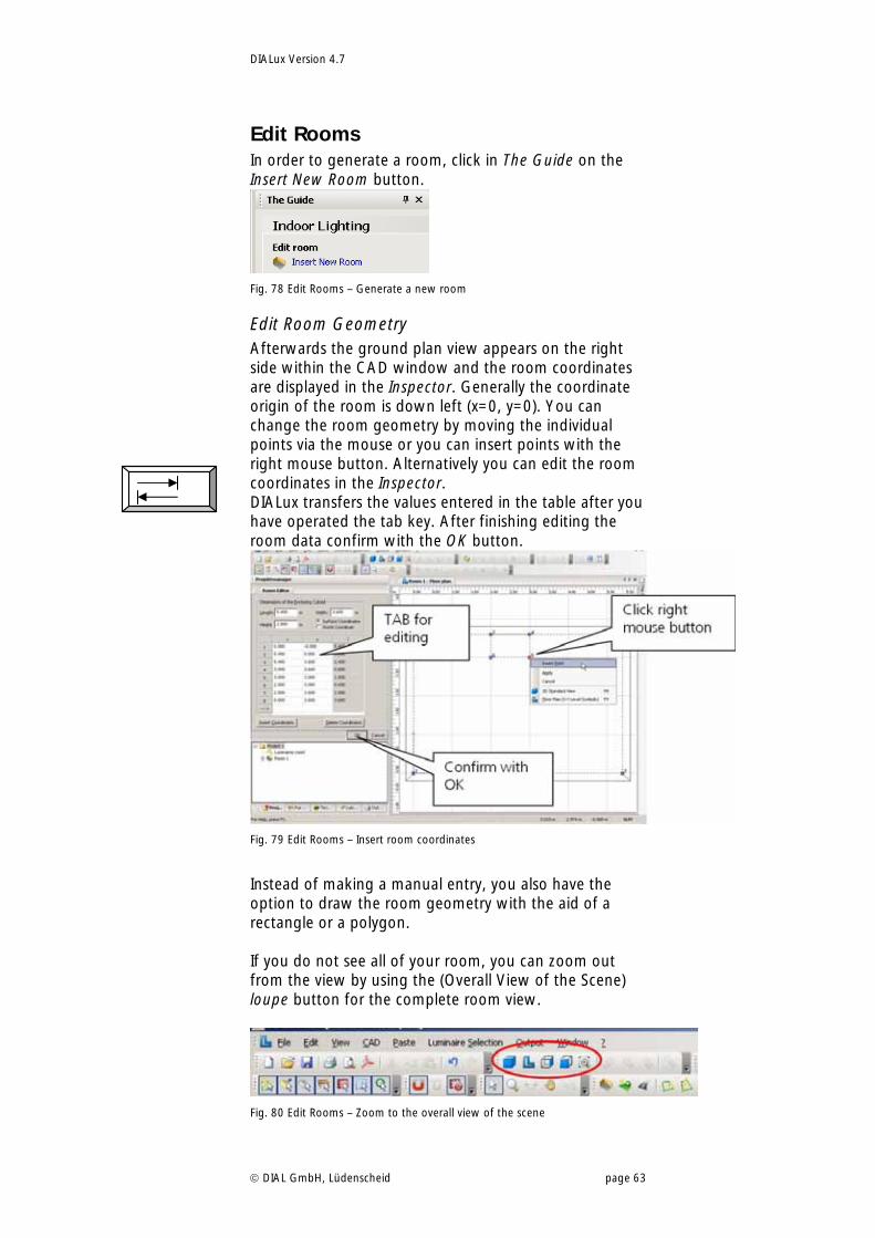
Project information in the file open dialog The file open dialog has changed in the latest version of DIALux. While opening an existing project the user can see the most important information about the file.
Fig. 77 Project preview
The information given in this dialogue about the project is the 3D view of the first room or exterior scene, information about the designer, the description and the name of the customer. The button “other folders” opens a list of directories formerly used to store DIALux projects in.
DIALux Version 4.7
DIAL GmbH, Lüdenscheid page 63
Edit Rooms In order to generate a room, click in The Guide on the Insert New Room button.
Fig. 78 Edit Rooms – Generate a new room
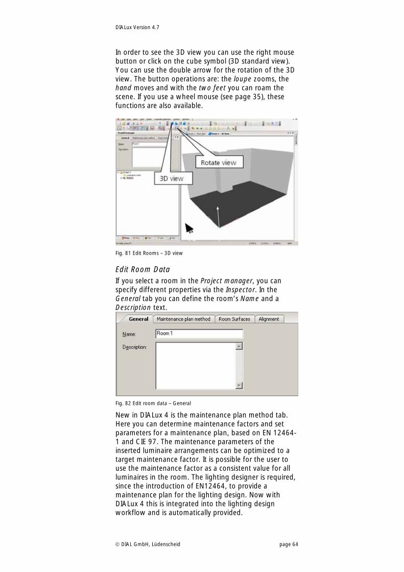
Edit Room Geometry Afterwards the ground plan view appears on the right side within the CAD window and the room coordinates are displayed in the Inspector. Generally the coordinate origin of the room is down left (x=0, y=0). You can change the room geometry by moving the individual points via the mouse or you can insert points with the right mouse button. Alternatively you can edit the room coordinates in the Inspector. DIALux transfers the values entered in the table after you have operated the tab key. After finishing editing the room data confirm with the OK button.
Fig. 79 Edit Rooms – Insert room coordinates
Instead of making a manual entry, you also have the option to draw the room geometry with the aid of a rectangle or a polygon. If you do not see all of your room, you can zoom out from the view by using the (Overall View of the Scene) loupe button for the complete room view.
Fig. 80 Edit Rooms – Zoom to the overall view of the scene
DIALux Version 4.7
DIAL GmbH, Lüdenscheid page 64
In order to see the 3D view you can use the right mouse button or click on the cube symbol (3D standard view). You can use the double arrow for the rotation of the 3D view. The button operations are: the loupe zooms, the hand moves and with the two feet you can roam the scene. If you use a wheel mouse (see page 35), these functions are also available.
Fig. 81 Edit Rooms – 3D view
Edit Room Data If you select a room in the Project manager, you can specify different properties via the Inspector. In the General tab you can define the room’s Name and a Description text.
Fig. 82 Edit room data – General
New in DIALux 4 is the maintenance plan method tab. Here you can determine maintenance factors and set parameters for a maintenance plan, based on EN 12464-1 and CIE 97. The maintenance parameters of the inserted luminaire arrangements can be optimized to a target maintenance factor. It is possible for the user to use the maintenance factor as a consistent value for all luminaires in the room. The lighting designer is required, since the introduction of EN12464, to provide a maintenance plan for the lighting design. Now with DIALux 4 this is integrated into the lighting design workflow and is automatically provided.
DIALux Version 4.7
DIAL GmbH, Lüdenscheid page 65
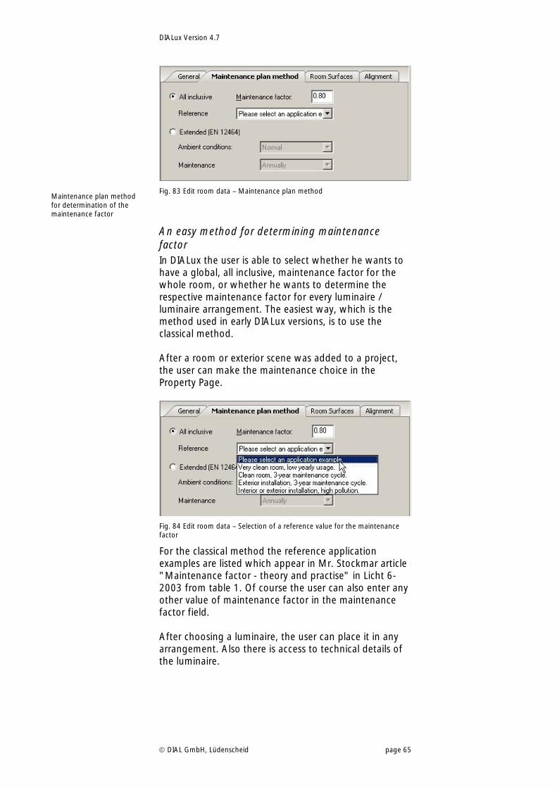
Fig. 83 Edit room data – Maintenance plan method
An easy method for determining maintenance factor In DIALux the user is able to select whether he wants to have a global, all inclusive, maintenance factor for the whole room, or whether he wants to determine the respective maintenance factor for every luminaire / luminaire arrangement. The easiest way, which is the method used in early DIALux versions, is to use the classical method. After a room or exterior scene was added to a project, the user can make the maintenance choice in the Property Page.
Fig. 84 Edit room data – Selection of a reference value for the maintenance factor
For the classical method the reference application examples are listed which appear in Mr. Stockmar article "Maintenance factor - theory and practise" in Licht 6-2003 from table 1. Of course the user can also enter any other value of maintenance factor in the maintenance factor field. After choosing a luminaire, the user can place it in any arrangement. Also there is access to technical details of the luminaire.
Maintenance plan method for determination of the maintenance factor
DIALux Version 4.7
DIAL GmbH, Lüdenscheid page 66
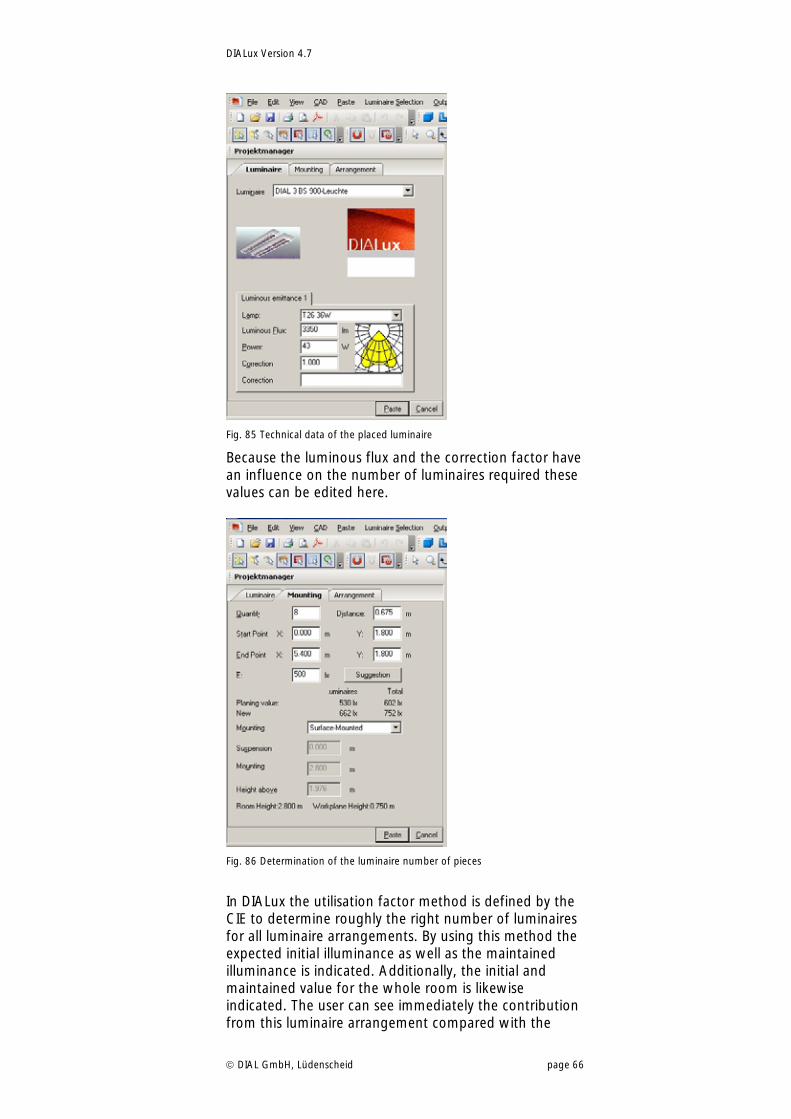
Fig. 85 Technical data of the placed luminaire
Because the luminous flux and the correction factor have an influence on the number of luminaires required these values can be edited here.
Fig. 86 Determination of the luminaire number of pieces
In DIALux the utilisation factor method is defined by the CIE to determine roughly the right number of luminaires for all luminaire arrangements. By using this method the expected initial illuminance as well as the maintained illuminance is indicated. Additionally, the initial and maintained value for the whole room is likewise indicated. The user can see immediately the contribution from this luminaire arrangement compared with the
DIALux Version 4.7
DIAL GmbH, Lüdenscheid page 67
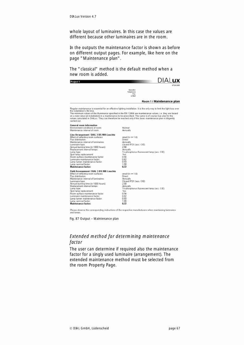
whole layout of luminaires. In this case the values are different because other luminaires are in the room. In the outputs the maintenance factor is shown as before on different output pages. For example, like here on the page "Maintenance plan". The "classical" method is the default method when a new room is added.
Fig. 87 Output – Maintenance plan
Extended method for determining maintenance factor The user can determine if required also the maintenance factor for a singly used luminaire (arrangement). The extended maintenance method must be selected from the room Property Page.
DIALux Version 4.7
DIAL GmbH, Lüdenscheid page 68
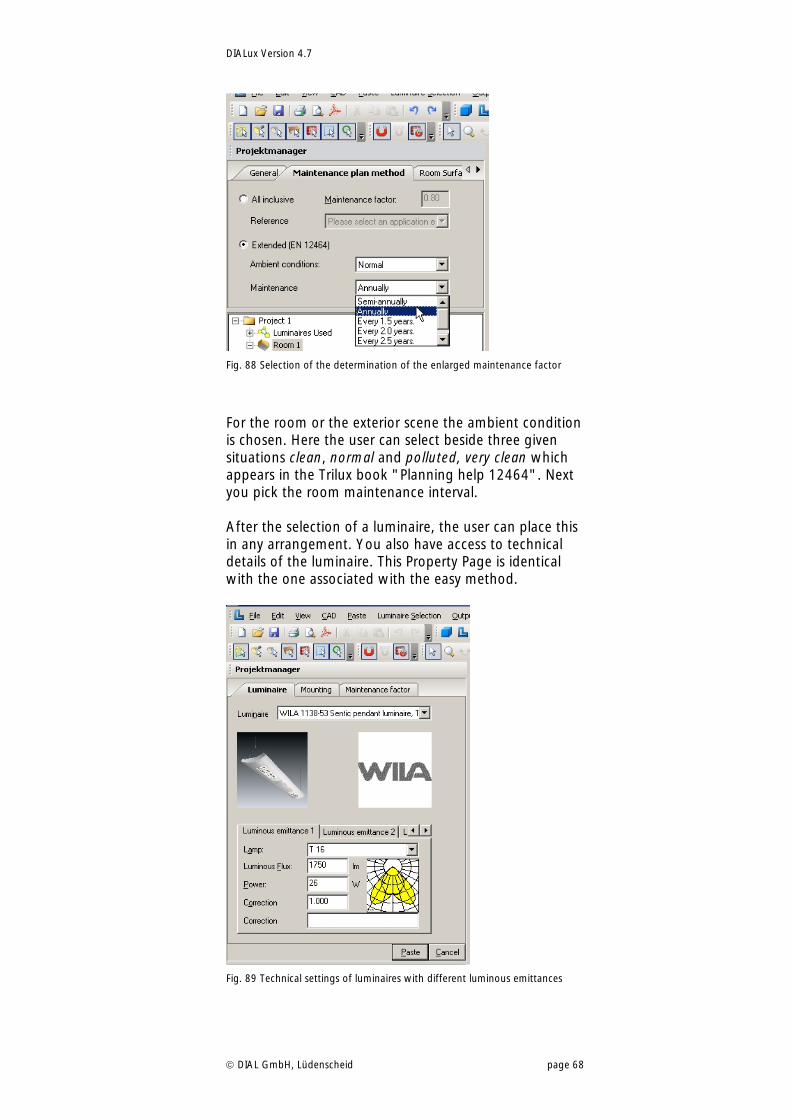
Fig. 88 Selection of the determination of the enlarged maintenance factor
For the room or the exterior scene the ambient condition is chosen. Here the user can select beside three given situations clean, normal and polluted, very clean which appears in the Trilux book "Planning help 12464". Next you pick the room maintenance interval. After the selection of a luminaire, the user can place this in any arrangement. You also have access to technical details of the luminaire. This Property Page is identical with the one associated with the easy method.
Fig. 89 Technical settings of luminaires with different luminous emittances
DIALux Version 4.7
DIAL GmbH, Lüdenscheid page 69
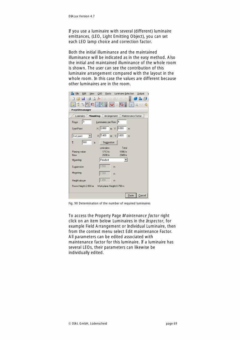
If you use a luminaire with several (different) luminaire emittances, (LEO, Light Emitting Object), you can set each LEO lamp choice and correction factor. Both the initial illuminance and the maintained illuminance will be indicated as in the easy method. Also the initial and maintained illuminance of the whole room is shown. The user can see the contribution of this luminaire arrangement compared with the layout in the whole room. In this case the values are different because other luminaires are in the room.
Fig. 90 Determination of the number of required luminaires
To access the Property Page Maintenance factor right click on an item below Luminaires in the Inspector, for example Field Arrangement or Individual Luminaire, then from the context menu select Edit maintenance Factor. All parameters can be edited associated with maintenance factor for this luminaire. If a luminaire has several LEOs, their parameters can likewise be individually edited.
DIALux Version 4.7
DIAL GmbH, Lüdenscheid page 70
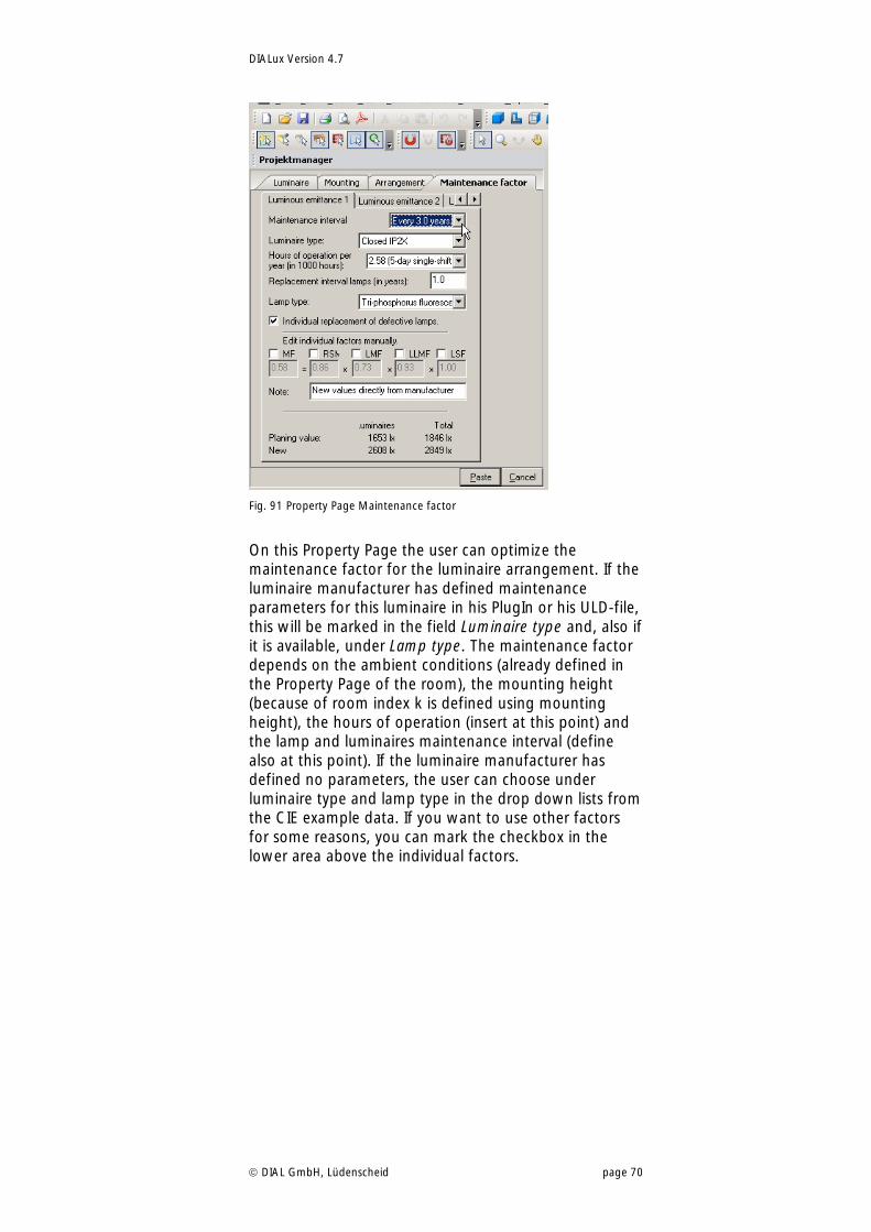
Fig. 91 Property Page Maintenance factor
On this Property Page the user can optimize the maintenance factor for the luminaire arrangement. If the luminaire manufacturer has defined maintenance parameters for this luminaire in his PlugIn or his ULD-file, this will be marked in the field Luminaire type and, also if it is available, under Lamp type. The maintenance factor depends on the ambient conditions (already defined in the Property Page of the room), the mounting height (because of room index k is defined using mounting height), the hours of operation (insert at this point) and the lamp and luminaires maintenance interval (define also at this point). If the luminaire manufacturer has defined no parameters, the user can choose under luminaire type and lamp type in the drop down lists from the CIE example data. If you want to use other factors for some reasons, you can mark the checkbox in the lower area above the individual factors.
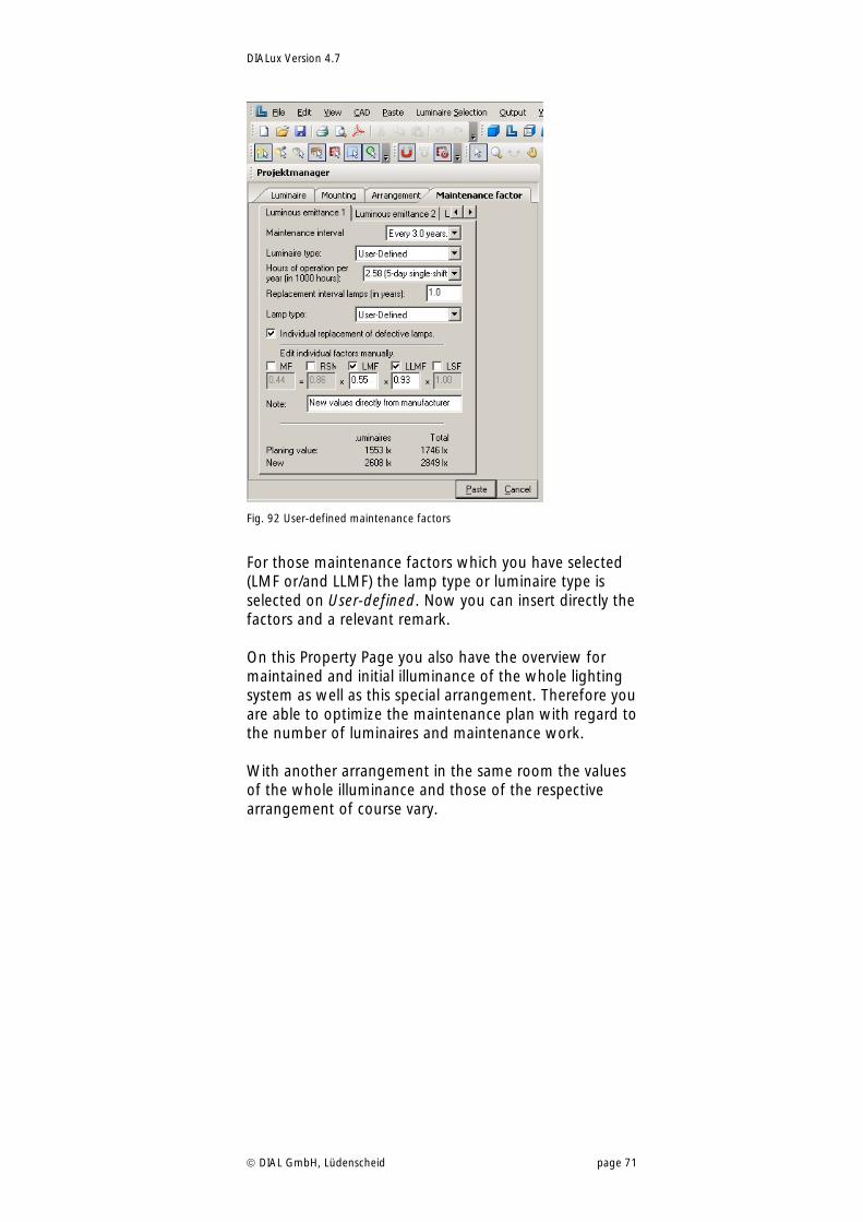
DIALux Version 4.7
DIAL GmbH, Lüdenscheid page 71
Fig. 92 User-defined maintenance factors
For those maintenance factors which you have selected (LMF or/and LLMF) the lamp type or luminaire type is selected on User-defined. Now you can insert directly the factors and a relevant remark. On this Property Page you also have the overview for maintained and initial illuminance of the whole lighting system as well as this special arrangement. Therefore you are able to optimize the maintenance plan with regard to the number of luminaires and maintenance work. With another arrangement in the same room the values of the whole illuminance and those of the respective arrangement of course vary.
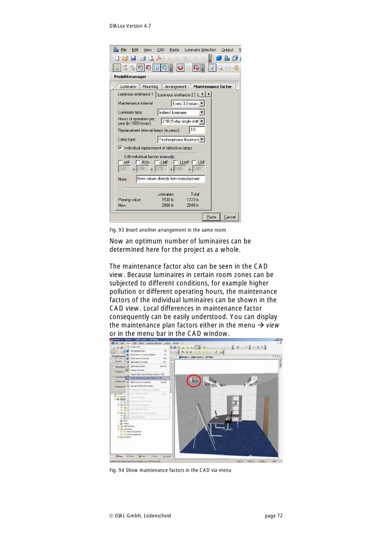
DIALux Version 4.7
DIAL GmbH, Lüdenscheid page 72
Fig. 93 Insert another arrangement in the same room
Now an optimum number of luminaires can be determined here for the project as a whole. The maintenance factor also can be seen in the CAD view. Because luminaires in certain room zones can be subjected to different conditions, for example higher pollution or different operating hours, the maintenance factors of the individual luminaires can be shown in the CAD view. Local differences in maintenance factor consequently can be easily understood. You can display the maintenance plan factors either in the menu view or in the menu bar in the CAD window.
Fig. 94 Show maintenance factors in the CAD via menu
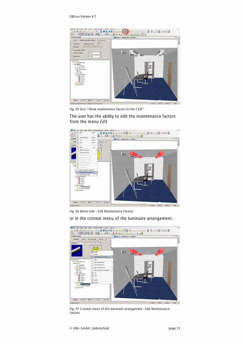
DIALux Version 4.7
DIAL GmbH, Lüdenscheid page 73
Fig. 95 Icon “Show maintenance factors in the CAD”
The user has the ability to edit the maintenance factors from the menu Edit
Fig. 96 Menu Edit – Edit Maintenance Factors
or in the context menu of the luminaire arrangement.
Fig. 97 Context menu of the luminaire arrangement - Edit Maintenance Factors
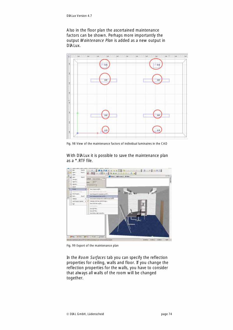
DIALux Version 4.7
DIAL GmbH, Lüdenscheid page 74
Also in the floor plan the ascertained maintenance factors can be shown. Perhaps more importantly the output Maintenance Plan is added as a new output in DIALux.
Fig. 98 View of the maintenance factors of individual luminaires in the CAD
With DIALux it is possible to save the maintenance plan as a *.RTF file.
Fig. 99 Export of the maintenance plan
In the Room Surfaces tab you can specify the reflection properties for ceiling, walls and floor. If you change the reflection properties for the walls, you have to consider that always all walls of the room will be changed together.
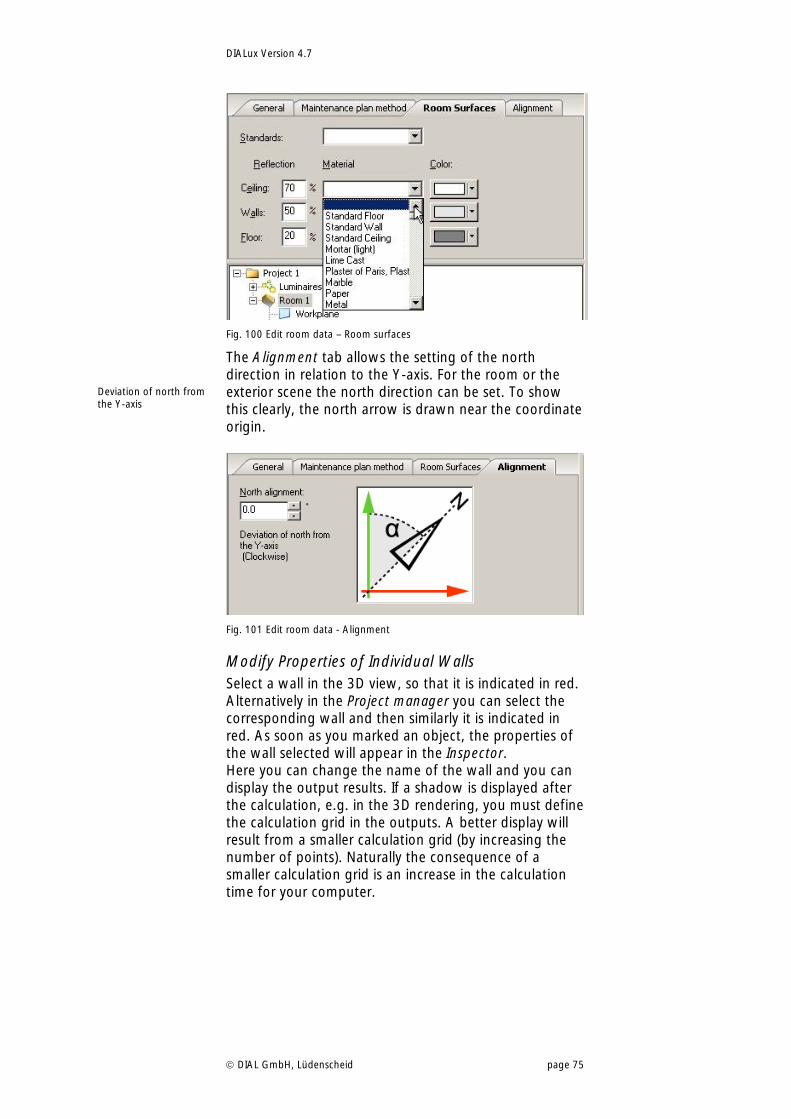
DIALux Version 4.7
DIAL GmbH, Lüdenscheid page 75
Fig. 100 Edit room data – Room surfaces
The Alignment tab allows the setting of the north direction in relation to the Y-axis. For the room or the exterior scene the north direction can be set. To show this clearly, the north arrow is drawn near the coordinate origin.
Fig. 101 Edit room data - Alignment
Modify Properties of Individual Walls Select a wall in the 3D view, so that it is indicated in red. Alternatively in the Project manager you can select the corresponding wall and then similarly it is indicated in red. As soon as you marked an object, the properties of the wall selected will appear in the Inspector. Here you can change the name of the wall and you can display the output results. If a shadow is displayed after the calculation, e.g. in the 3D rendering, you must define the calculation grid in the outputs. A better display will result from a smaller calculation grid (by increasing the number of points). Naturally the consequence of a smaller calculation grid is an increase in the calculation time for your computer.
Deviation of north from the Y-axis
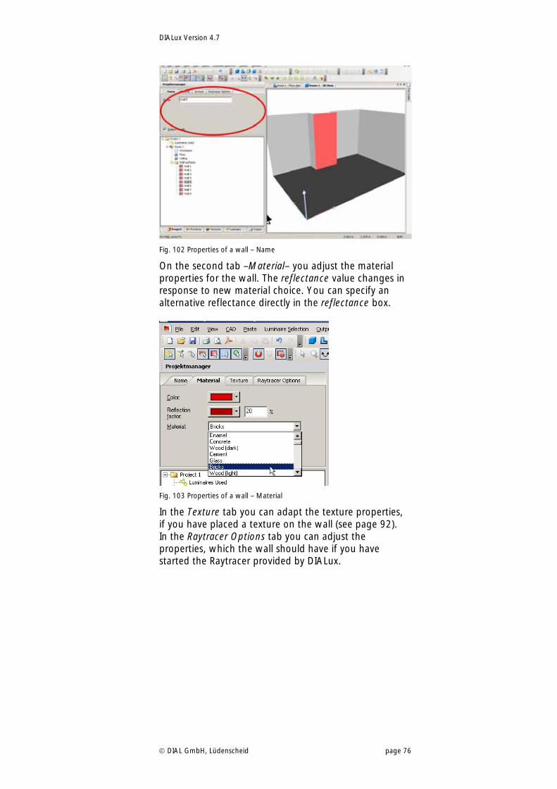
DIALux Version 4.7
DIAL GmbH, Lüdenscheid page 76
Fig. 102 Properties of a wall – Name
On the second tab –Material– you adjust the material properties for the wall. The reflectance value changes in response to new material choice. You can specify an alternative reflectance directly in the reflectance box.
Fig. 103 Properties of a wall – Material
In the Texture tab you can adapt the texture properties, if you have placed a texture on the wall (see page 92). In the Raytracer Options tab you can adjust the properties, which the wall should have if you have started the Raytracer provided by DIALux.
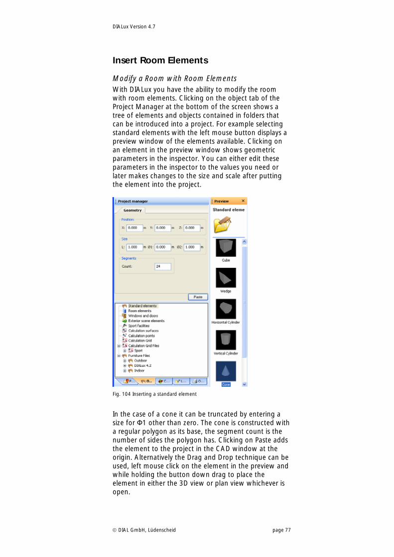
DIALux Version 4.7
DIAL GmbH, Lüdenscheid page 77
Insert Room Elements
Modify a Room with Room Elements With DIALux you have the ability to modify the room with room elements. Clicking on the object tab of the Project Manager at the bottom of the screen shows a tree of elements and objects contained in folders that can be introduced into a project. For example selecting standard elements with the left mouse button displays a preview window of the elements available. Clicking on an element in the preview window shows geometric parameters in the inspector. You can either edit these parameters in the inspector to the values you need or later makes changes to the size and scale after putting the element into the project.
Fig. 104 Inserting a standard element
In the case of a cone it can be truncated by entering a size for Ф1 other than zero. The cone is constructed with a regular polygon as its base, the segment count is the number of sides the polygon has. Clicking on Paste adds the element to the project in the CAD window at the origin. Alternatively the Drag and Drop technique can be used, left mouse click on the element in the preview and while holding the button down drag to place the element in either the 3D view or plan view whichever is open.
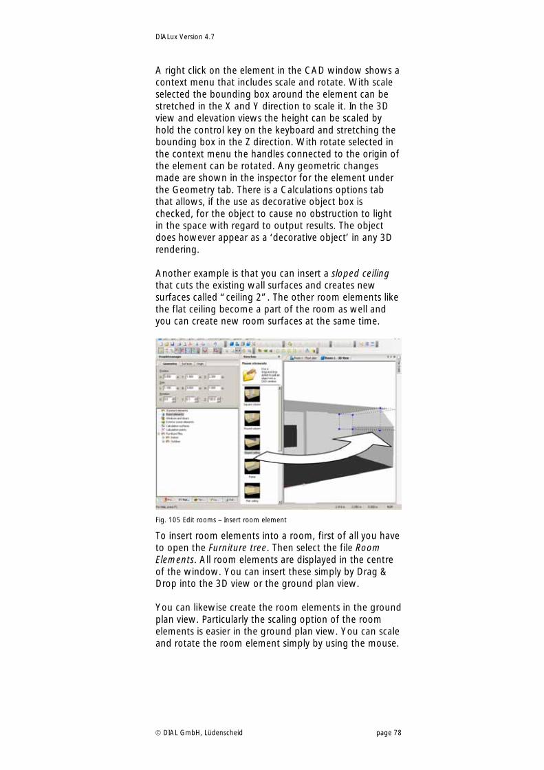
DIALux Version 4.7
DIAL GmbH, Lüdenscheid page 78
A right click on the element in the CAD window shows a context menu that includes scale and rotate. With scale selected the bounding box around the element can be stretched in the X and Y direction to scale it. In the 3D view and elevation views the height can be scaled by hold the control key on the keyboard and stretching the bounding box in the Z direction. With rotate selected in the context menu the handles connected to the origin of the element can be rotated. Any geometric changes made are shown in the inspector for the element under the Geometry tab. There is a Calculations options tab that allows, if the use as decorative object box is checked, for the object to cause no obstruction to light in the space with regard to output results. The object does however appear as a ‘decorative object’ in any 3D rendering. Another example is that you can insert a sloped ceiling that cuts the existing wall surfaces and creates new surfaces called “ceiling 2”. The other room elements like the flat ceiling become a part of the room as well and you can create new room surfaces at the same time.
Fig. 105 Edit rooms – Insert room element
To insert room elements into a room, first of all you have to open the Furniture tree. Then select the file Room Elements. All room elements are displayed in the centre of the window. You can insert these simply by Drag & Drop into the 3D view or the ground plan view. You can likewise create the room elements in the ground plan view. Particularly the scaling option of the room elements is easier in the ground plan view. You can scale and rotate the room element simply by using the mouse.
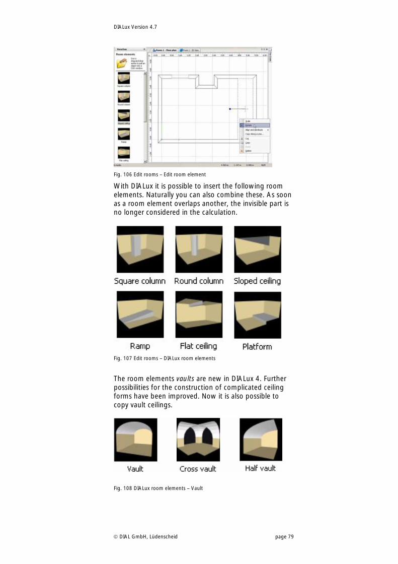
DIALux Version 4.7
DIAL GmbH, Lüdenscheid page 79
Fig. 106 Edit rooms – Edit room element
With DIALux it is possible to insert the following room elements. Naturally you can also combine these. As soon as a room element overlaps another, the invisible part is no longer considered in the calculation.
Fig. 107 Edit rooms – DIALux room elements
The room elements vaults are new in DIALux 4. Further possibilities for the construction of complicated ceiling forms have been improved. Now it is also possible to copy vault ceilings.
Fig. 108 DIALux room elements – Vault
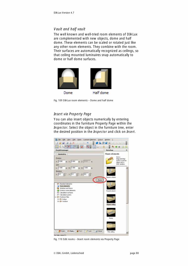
DIALux Version 4.7
DIAL GmbH, Lüdenscheid page 80
Vault and half vault The well known and well-tried room elements of DIALux are complemented with new objects, dome and half dome. These elements can be scaled or rotated just like any other room elements. They combine with the room. Their surfaces are automatically recognized as ceilings, so that ceiling mounted luminaires snap automatically to dome or half dome surfaces.
Fig. 109 DIALux room elements – Dome and half dome
Insert via Property Page You can also insert objects numerically by entering coordinates in the furniture Property Page within the Inspector. Select the object in the furniture tree, enter the desired position in the Inspector and click on Insert.
Fig. 110 Edit rooms – Insert room elements via Property Page
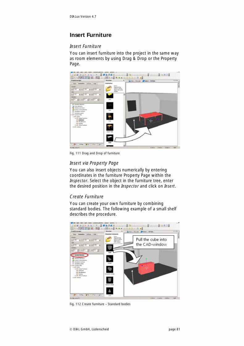
DIALux Version 4.7
DIAL GmbH, Lüdenscheid page 81
Insert Furniture
Insert Furniture You can insert furniture into the project in the same way as room elements by using Drag & Drop or the Property Page.
Fig. 111 Drag and Drop of furniture
Insert via Property Page You can also insert objects numerically by entering coordinates in the furniture Property Page within the Inspector. Select the object in the furniture tree, enter the desired position in the Inspector and click on Insert.
Create Furniture You can create your own furniture by combining standard bodies. The following example of a small shelf describes the procedure.
Fig. 112 Create furniture – Standard bodies
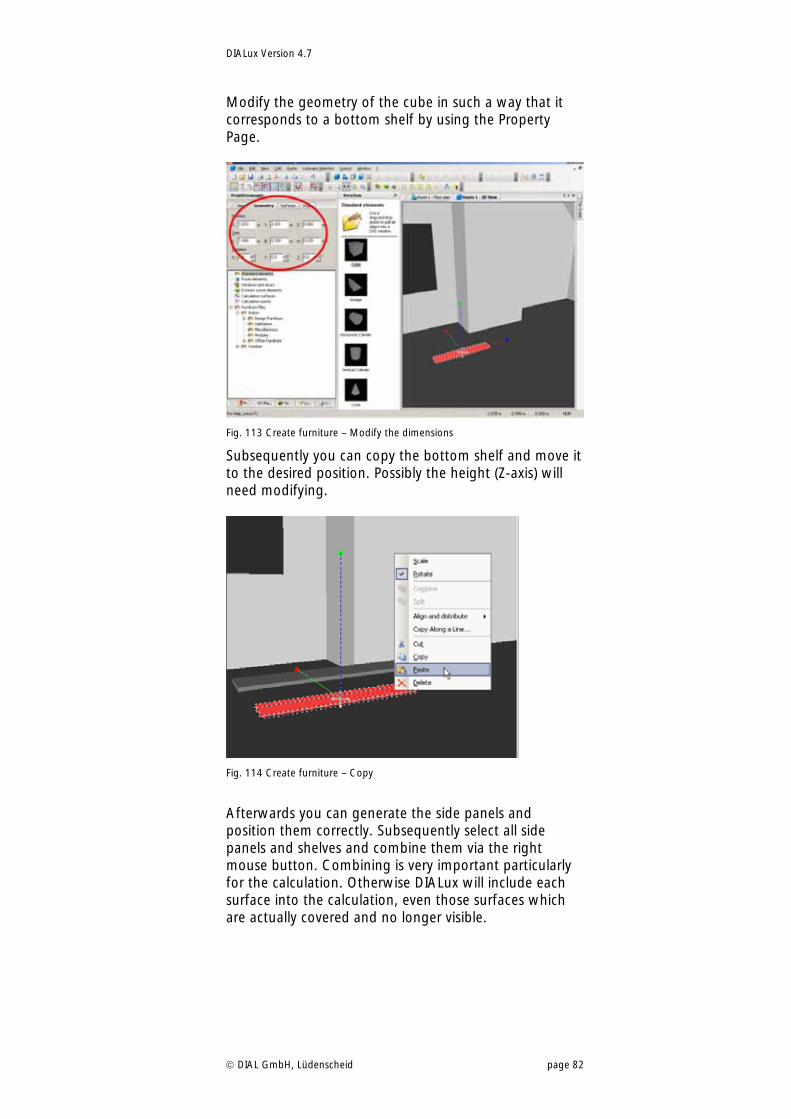
DIALux Version 4.7
DIAL GmbH, Lüdenscheid page 82
Modify the geometry of the cube in such a way that it corresponds to a bottom shelf by using the Property Page.
Fig. 113 Create furniture – Modify the dimensions
Subsequently you can copy the bottom shelf and move it to the desired position. Possibly the height (Z-axis) will need modifying.
Fig. 114 Create furniture – Copy
Afterwards you can generate the side panels and position them correctly. Subsequently select all side panels and shelves and combine them via the right mouse button. Combining is very important particularly for the calculation. Otherwise DIALux will include each surface into the calculation, even those surfaces which are actually covered and no longer visible.
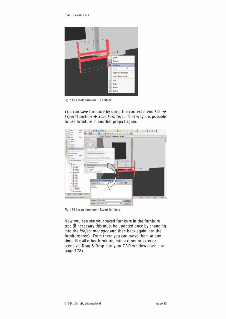
DIALux Version 4.7
DIAL GmbH, Lüdenscheid page 83
Fig. 115 Create furniture – Combine
You can save furniture by using the context menu File Export function Save Furniture. That way it is possible to use furniture in another project again.
Fig. 116 Create furniture – Export furniture
Now you can see your saved furniture in the furniture tree (if necessary this must be updated once by changing into the Project manager and then back again into the furniture tree). From there you can move them at any time, like all other furniture, into a room or exterior scene via Drag & Drop into your CAD windows (see also page 178).
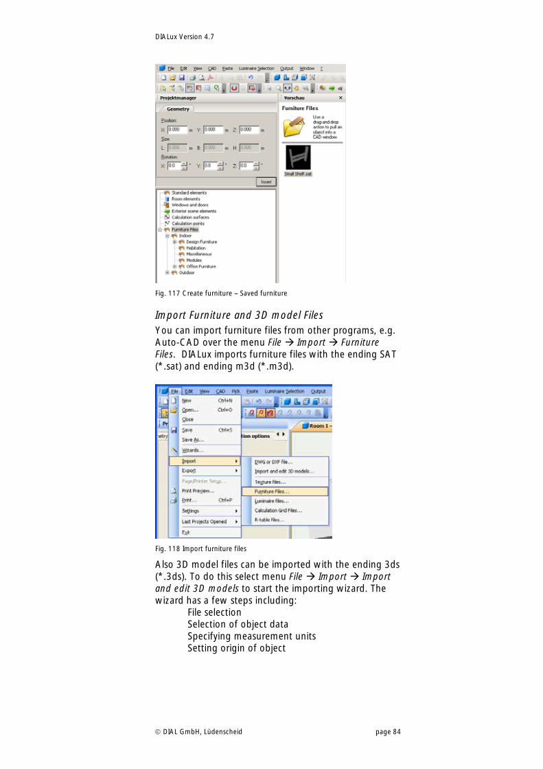
DIALux Version 4.7
DIAL GmbH, Lüdenscheid page 84
Fig. 117 Create furniture – Saved furniture
Import Furniture and 3D model Files You can import furniture files from other programs, e.g. Auto-CAD over the menu File Import Furniture Files. DIALux imports furniture files with the ending SAT (*.sat) and ending m3d (*.m3d).
Fig. 118 Import furniture files
Also 3D model files can be imported with the ending 3ds (*.3ds). To do this select menu File Import Import and edit 3D models to start the importing wizard. The wizard has a few steps including: File selection Selection of object data Specifying measurement units Setting origin of object
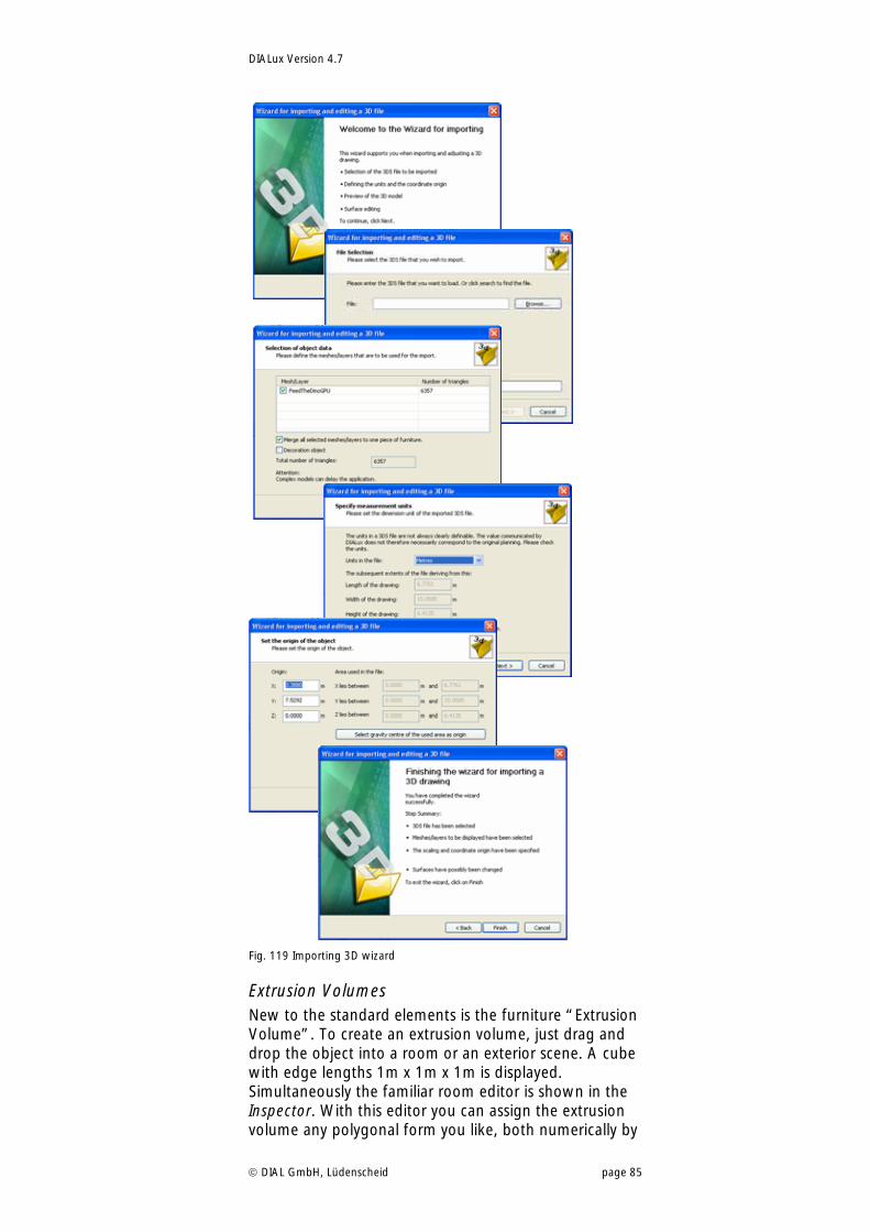
DIALux Version 4.7
DIAL GmbH, Lüdenscheid page 85
Fig. 119 Importing 3D wizard
Extrusion Volumes New to the standard elements is the furniture “Extrusion Volume”. To create an extrusion volume, just drag and drop the object into a room or an exterior scene. A cube with edge lengths 1m x 1m x 1m is displayed. Simultaneously the familiar room editor is shown in the Inspector. With this editor you can assign the extrusion volume any polygonal form you like, both numerically by
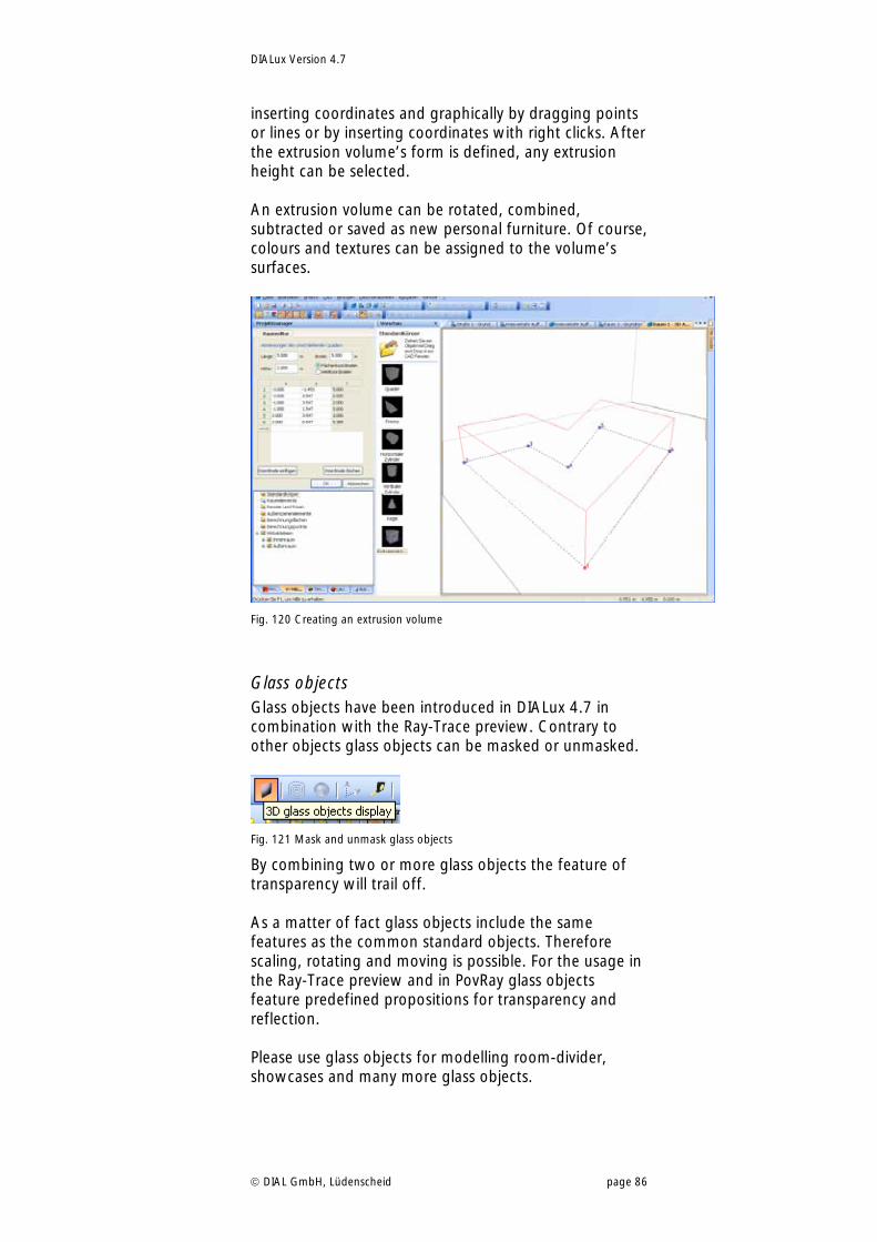
DIALux Version 4.7
DIAL GmbH, Lüdenscheid page 86
inserting coordinates and graphically by dragging points or lines or by inserting coordinates with right clicks. After the extrusion volume’s form is defined, any extrusion height can be selected. An extrusion volume can be rotated, combined, subtracted or saved as new personal furniture. Of course, colours and textures can be assigned to the volume’s surfaces.
Fig. 120 Creating an extrusion volume
Glass objects Glass objects have been introduced in DIALux 4.7 in combination with the Ray-Trace preview. Contrary to other objects glass objects can be masked or unmasked.
Fig. 121 Mask and unmask glass objects
By combining two or more glass objects the feature of transparency will trail off. As a matter of fact glass objects include the same features as the common standard objects. Therefore scaling, rotating and moving is possible. For the usage in the Ray-Trace preview and in PovRay glass objects feature predefined propositions for transparency and reflection. Please use glass objects for modelling room-divider, showcases and many more glass objects.
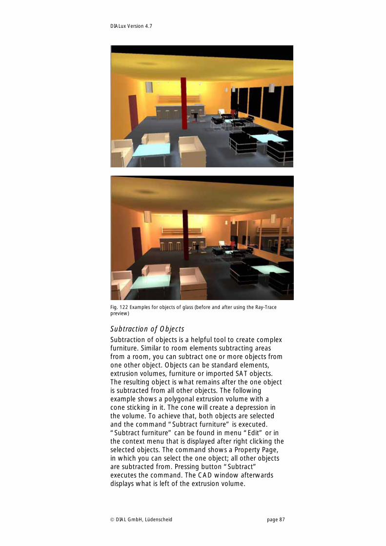
DIALux Version 4.7
DIAL GmbH, Lüdenscheid page 87
Fig. 122 Examples for objects of glass (before and after using the Ray-Trace preview)
Subtraction of Objects Subtraction of objects is a helpful tool to create complex furniture. Similar to room elements subtracting areas from a room, you can subtract one or more objects from one other object. Objects can be standard elements, extrusion volumes, furniture or imported SAT objects. The resulting object is what remains after the one object is subtracted from all other objects. The following example shows a polygonal extrusion volume with a cone sticking in it. The cone will create a depression in the volume. To achieve that, both objects are selected and the command “Subtract furniture” is executed. “Subtract furniture” can be found in menu “Edit” or in the context menu that is displayed after right clicking the selected objects. The command shows a Property Page, in which you can select the one object; all other objects are subtracted from. Pressing button “Subtract” executes the command. The CAD window afterwards displays what is left of the extrusion volume.
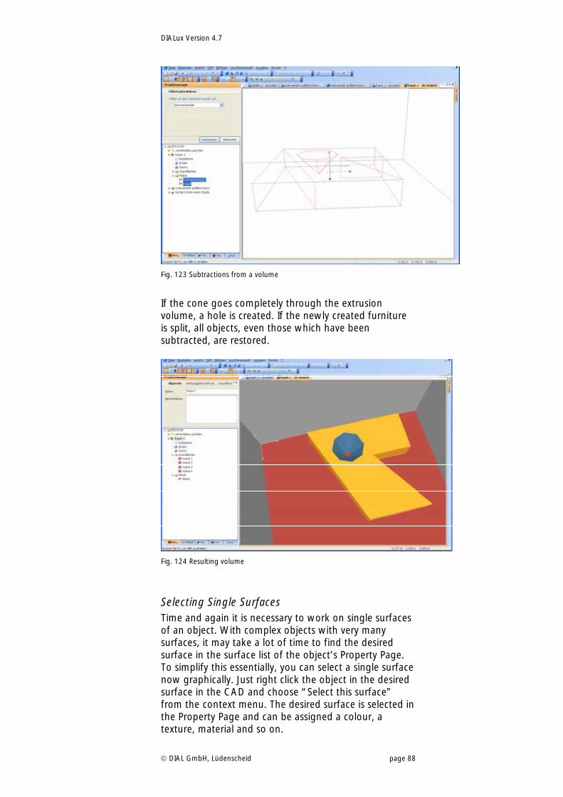
DIALux Version 4.7
DIAL GmbH, Lüdenscheid page 88
Fig. 123 Subtractions from a volume
If the cone goes completely through the extrusion volume, a hole is created. If the newly created furniture is split, all objects, even those which have been subtracted, are restored.
Fig. 124 Resulting volume
Selecting Single Surfaces Time and again it is necessary to work on single surfaces of an object. With complex objects with very many surfaces, it may take a lot of time to find the desired surface in the surface list of the object’s Property Page. To simplify this essentially, you can select a single surface now graphically. Just right click the object in the desired surface in the CAD and choose “Select this surface” from the context menu. The desired surface is selected in the Property Page and can be assigned a colour, a texture, material and so on.
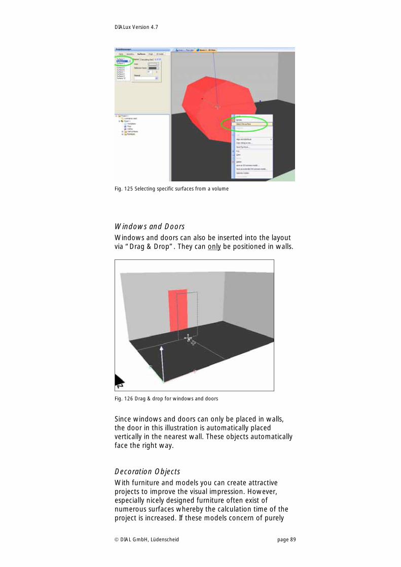
DIALux Version 4.7
DIAL GmbH, Lüdenscheid page 89
Fig. 125 Selecting specific surfaces from a volume
Windows and Doors Windows and doors can also be inserted into the layout via “Drag & Drop”. They can only be positioned in walls.
Fig. 126 Drag & drop for windows and doors
Since windows and doors can only be placed in walls, the door in this illustration is automatically placed vertically in the nearest wall. These objects automatically face the right way.
Decoration Objects With furniture and models you can create attractive projects to improve the visual impression. However, especially nicely designed furniture often exist of numerous surfaces whereby the calculation time of the project is increased. If these models concern of purely
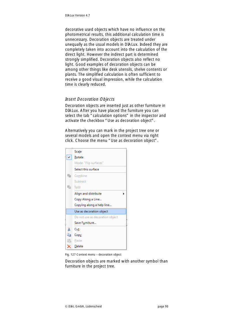
DIALux Version 4.7
DIAL GmbH, Lüdenscheid page 90
decorative used objects which have no influence on the photometrical results, this additional calculation time is unnecessary. Decoration objects are treated under unequally as the usual models in DIALux. Indeed they are completely taken into account into the calculation of the direct light. However the indirect part is determined strongly simplified. Decoration objects also reflect no light. Good examples of decoration objects can be among other things like desk utensils, shelve contents or plants. The simplified calculation is often sufficient to receive a good visual impression, while the calculation time is clearly reduced.
Insert Decoration Objects Decoration objects are inserted just as other furniture in DIALux. After you have placed the furniture you can select the tab “calculation options” in the inspector and activate the checkbox “Use as decoration object”. Alternatively you can mark in the project tree one or several models and open the context menu via right click. Choose the menu “Use as decoration object”.
Fig. 127 Context menu – decoration object
Decoration objects are marked with another symbol than furniture in the project tree.
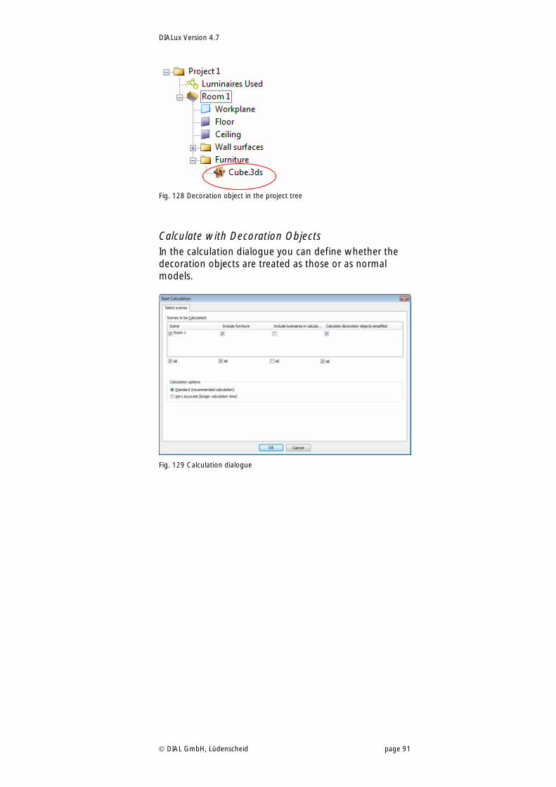
DIALux Version 4.7
DIAL GmbH, Lüdenscheid page 91
Fig. 128 Decoration object in the project tree
Calculate with Decoration Objects In the calculation dialogue you can define whether the decoration objects are treated as those or as normal models.
Fig. 129 Calculation dialogue
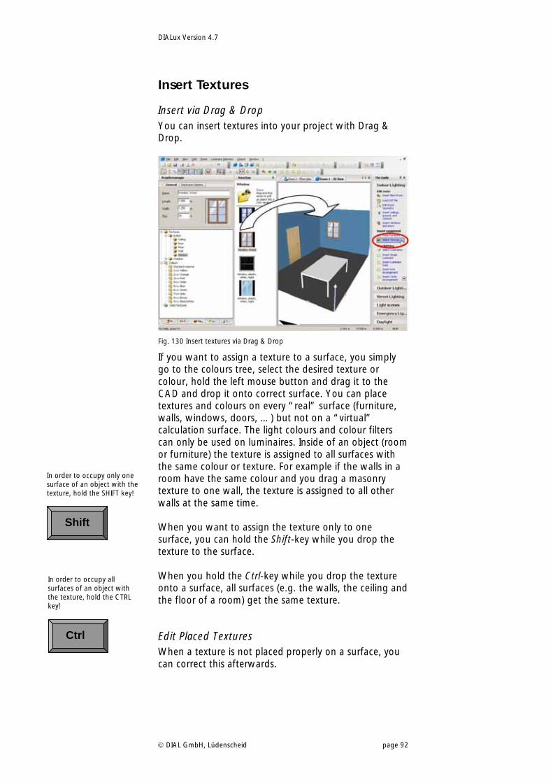
DIALux Version 4.7
DIAL GmbH, Lüdenscheid page 92
Insert Textures
Insert via Drag & Drop You can insert textures into your project with Drag & Drop.
Fig. 130 Insert textures via Drag & Drop
If you want to assign a texture to a surface, you simply go to the colours tree, select the desired texture or colour, hold the left mouse button and drag it to the CAD and drop it onto correct surface. You can place textures and colours on every “real” surface (furniture, walls, windows, doors, …) but not on a “virtual” calculation surface. The light colours and colour filters can only be used on luminaires. Inside of an object (room or furniture) the texture is assigned to all surfaces with the same colour or texture. For example if the walls in a room have the same colour and you drag a masonry texture to one wall, the texture is assigned to all other walls at the same time. When you want to assign the texture only to one surface, you can hold the Shift-key while you drop the texture to the surface. When you hold the Ctrl-key while you drop the texture onto a surface, all surfaces (e.g. the walls, the ceiling and the floor of a room) get the same texture.
Edit Placed Textures When a texture is not placed properly on a surface, you can correct this afterwards.
In order to occupy only one surface of an object with the texture, hold the SHIFT key!
Shift
In order to occupy all surfaces of an object with the texture, hold the CTRL key!
Ctrl
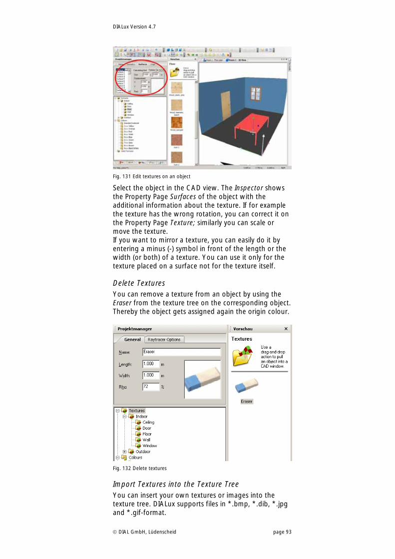
DIALux Version 4.7
DIAL GmbH, Lüdenscheid page 93
Fig. 131 Edit textures on an object
Select the object in the CAD view. The Inspector shows the Property Page Surfaces of the object with the additional information about the texture. If for example the texture has the wrong rotation, you can correct it on the Property Page Texture; similarly you can scale or move the texture. If you want to mirror a texture, you can easily do it by entering a minus (-) symbol in front of the length or the width (or both) of a texture. You can use it only for the texture placed on a surface not for the texture itself.
Delete Textures You can remove a texture from an object by using the Eraser from the texture tree on the corresponding object. Thereby the object gets assigned again the origin colour.
Fig. 132 Delete textures
Import Textures into the Texture Tree You can insert your own textures or images into the texture tree. DIALux supports files in *.bmp, *.dib, *.jpg and *.gif-format.
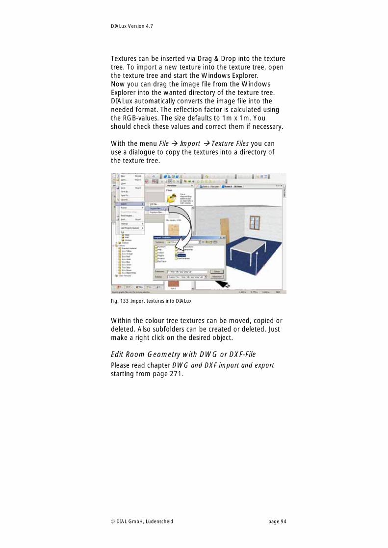
DIALux Version 4.7
DIAL GmbH, Lüdenscheid page 94
Textures can be inserted via Drag & Drop into the texture tree. To import a new texture into the texture tree, open the texture tree and start the Windows Explorer. Now you can drag the image file from the Windows Explorer into the wanted directory of the texture tree. DIALux automatically converts the image file into the needed format. The reflection factor is calculated using the RGB-values. The size defaults to 1m x 1m. You should check these values and correct them if necessary. With the menu File Import Texture Files you can use a dialogue to copy the textures into a directory of the texture tree.
Fig. 133 Import textures into DIALux
Within the colour tree textures can be moved, copied or deleted. Also subfolders can be created or deleted. Just make a right click on the desired object.
Edit Room Geometry with DWG or DXF-File Please read chapter DWG and DXF import and export starting from page 271.
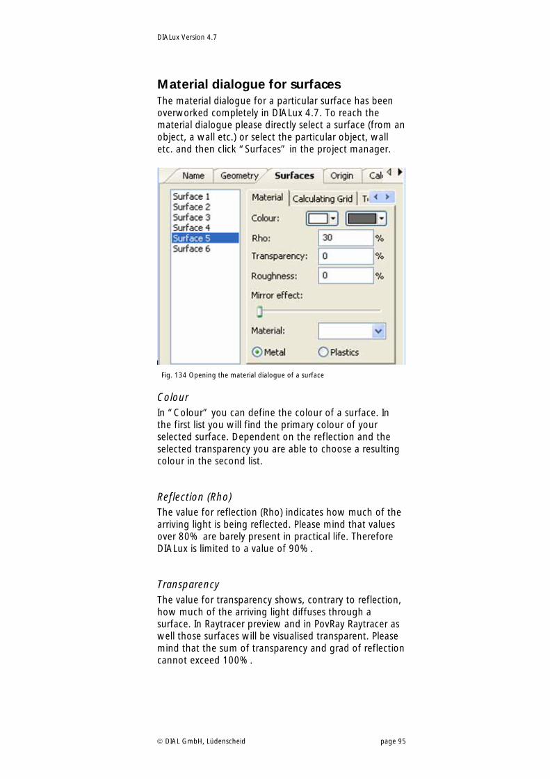
DIALux Version 4.7
DIAL GmbH, Lüdenscheid page 95
Material dialogue for surfaces The material dialogue for a particular surface has been overworked completely in DIALux 4.7. To reach the material dialogue please directly select a surface (from an object, a wall etc.) or select the particular object, wall etc. and then click “Surfaces” in the project manager.
Fig. 134 Opening the material dialogue of a surface
Colour In “Colour” you can define the colour of a surface. In the first list you will find the primary colour of your selected surface. Dependent on the reflection and the selected transparency you are able to choose a resulting colour in the second list.
Reflection (Rho) The value for reflection (Rho) indicates how much of the arriving light is being reflected. Please mind that values over 80% are barely present in practical life. Therefore DIALux is limited to a value of 90%.
Transparency The value for transparency shows, contrary to reflection, how much of the arriving light diffuses through a surface. In Raytracer preview and in PovRay Raytracer as well those surfaces will be visualised transparent. Please mind that the sum of transparency and grad of reflection cannot exceed 100%.
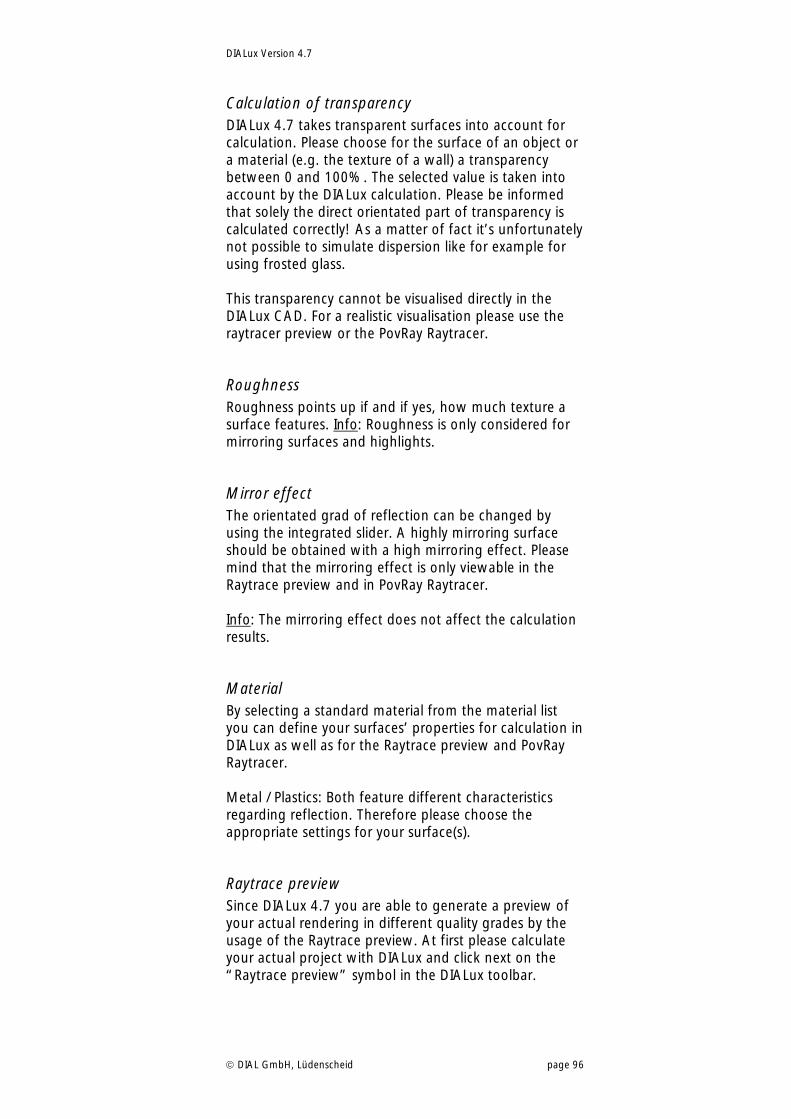
DIALux Version 4.7
DIAL GmbH, Lüdenscheid page 96
Calculation of transparency DIALux 4.7 takes transparent surfaces into account for calculation. Please choose for the surface of an object or a material (e.g. the texture of a wall) a transparency between 0 and 100%. The selected value is taken into account by the DIALux calculation. Please be informed that solely the direct orientated part of transparency is calculated correctly! As a matter of fact it’s unfortunately not possible to simulate dispersion like for example for using frosted glass. This transparency cannot be visualised directly in the DIALux CAD. For a realistic visualisation please use the raytracer preview or the PovRay Raytracer.
Roughness Roughness points up if and if yes, how much texture a surface features. Info: Roughness is only considered for mirroring surfaces and highlights.
Mirror effect The orientated grad of reflection can be changed by using the integrated slider. A highly mirroring surface should be obtained with a high mirroring effect. Please mind that the mirroring effect is only viewable in the Raytrace preview and in PovRay Raytracer. Info: The mirroring effect does not affect the calculation results.
Material By selecting a standard material from the material list you can define your surfaces’ properties for calculation in DIALux as well as for the Raytrace preview and PovRay Raytracer. Metal / Plastics: Both feature different characteristics regarding reflection. Therefore please choose the appropriate settings for your surface(s).
Raytrace preview Since DIALux 4.7 you are able to generate a preview of your actual rendering in different quality grades by the usage of the Raytrace preview. At first please calculate your actual project with DIALux and click next on the “Raytrace preview” symbol in the DIALux toolbar.
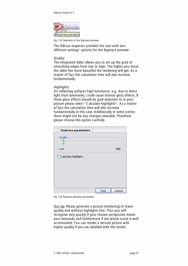
DIALux Version 4.7
DIAL GmbH, Lüdenscheid page 97
Fig. 135 Selection of the Raytrace preview
The DIALux inspector provides the user with two different settings’ options for the Raytrace preview: Quality: The integrated slider allows you to set up the grad of smoothing edges from low to high. The higher you move the slider the more beautiful the rendering will get. As a matter of fact the calculation time will also increase fundamentally. Highlights: On reflecting surfaces high luminance, e.g. due to direct light from luminaries, could cause intense gloss effects. If these gloss effects should be paid attention to in your picture please select “Calculate highlights”. As a matter of fact the calculation time will also increase fundamentally in this case. Additionally in some scenes there might not be any changes viewable. Therefore please choose this option carefully.
Fig. 136 Raytrace preview parameters
Our tip: Please generate a picture (rendering) in lower quality and without highlights first. Thus you will recognise very quickly if your chosen perspective meets your demands and furthermore if the whole scene is well accentuated. You can render a second picture with higher quality if you are satisfied with the results.
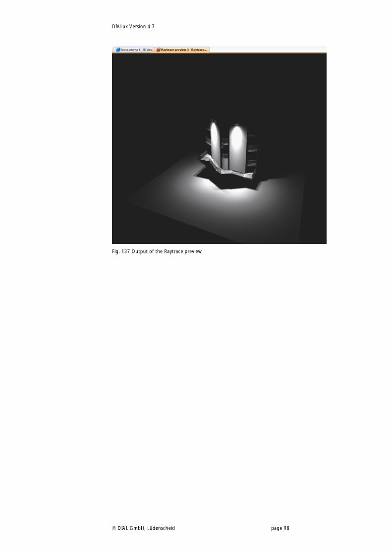
DIALux Version 4.7
DIAL GmbH, Lüdenscheid page 98
Fig. 137 Output of the Raytrace preview
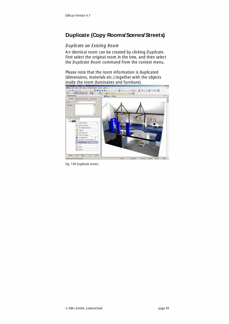
DIALux Version 4.7
DIAL GmbH, Lüdenscheid page 99
Duplicate (Copy Rooms/Scenes/Streets)
Duplicate an Existing Room An identical room can be created by clicking Duplicate. First select the original room in the tree, and then select the Duplicate Room command from the context menu. Please note that the room information is duplicated (dimensions, materials etc.) together with the objects inside the room (luminaires and furniture).
Fig. 138 Duplicate rooms
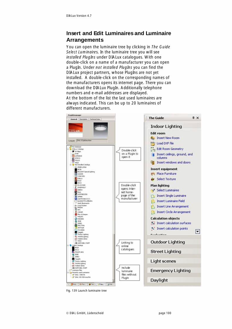
DIALux Version 4.7
DIAL GmbH, Lüdenscheid page 100
Insert and Edit Luminaires and Luminaire Arrangements You can open the luminaire tree by clicking in The Guide Select Luminaires. In the luminaire tree you will see installed PlugIns under DIALux catalogues. With one double-click on a name of a manufacturer you can open a PlugIn. Under not installed PlugIns you can find the DIALux project partners, whose PlugIns are not yet installed. A double-click on the corresponding names of the manufacturers opens its internet page. There you can download the DIALux PlugIn. Additionally telephone numbers and e-mail addresses are displayed. At the bottom of the list the last used luminaires are always indicated. This can be up to 20 luminaires of different manufacturers.
Fig. 139 Launch luminaire tree
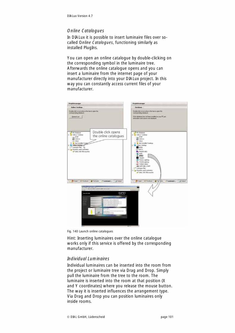
DIALux Version 4.7
DIAL GmbH, Lüdenscheid page 101
Online Catalogues In DIALux it is possible to insert luminaire files over so-called Online Catalogues, functioning similarly as installed PlugIns. You can open an online catalogue by double-clicking on the corresponding symbol in the luminaire tree. Afterwards the online catalogue opens and you can insert a luminaire from the internet page of your manufacturer directly into your DIALux project. In this way you can constantly access current files of your manufacturer.
Fig. 140 Launch online catalogues
Hint: Inserting luminaires over the online catalogue works only if this service is offered by the corresponding manufacturer.
Individual Luminaires Individual luminaires can be inserted into the room from the project or luminaire tree via Drag and Drop. Simply pull the luminaire from the tree to the room. The luminaire is inserted into the room at that position (X and Y coordinates) where you release the mouse button. The way it is inserted influences the arrangement type. Via Drag and Drop you can position luminaires only inside rooms.
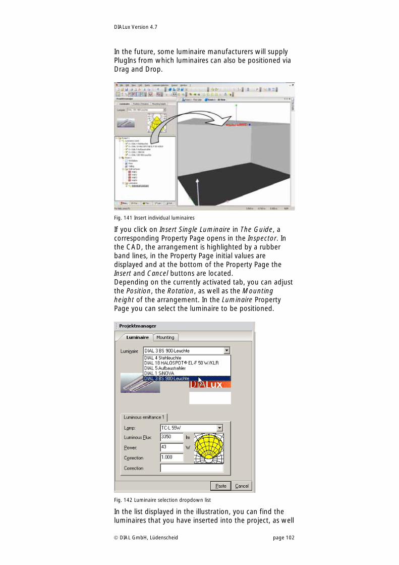
DIALux Version 4.7
DIAL GmbH, Lüdenscheid page 102
In the future, some luminaire manufacturers will supply PlugIns from which luminaires can also be positioned via Drag and Drop.
Fig. 141 Insert individual luminaires
If you click on Insert Single Luminaire in The Guide, a corresponding Property Page opens in the Inspector. In the CAD, the arrangement is highlighted by a rubber band lines, in the Property Page initial values are displayed and at the bottom of the Property Page the Insert and Cancel buttons are located. Depending on the currently activated tab, you can adjust the Position, the Rotation, as well as the Mounting height of the arrangement. In the Luminaire Property Page you can select the luminaire to be positioned.
Fig. 142 Luminaire selection dropdown list
In the list displayed in the illustration, you can find the luminaires that you have inserted into the project, as well
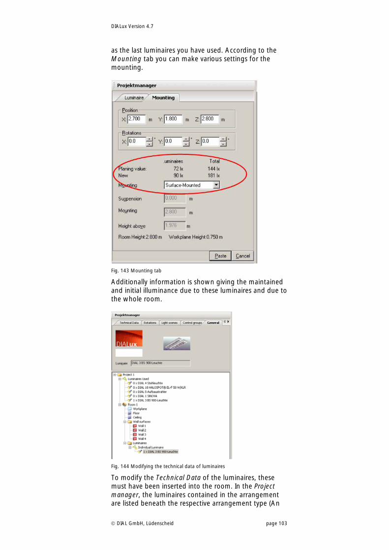
DIALux Version 4.7
DIAL GmbH, Lüdenscheid page 103
as the last luminaires you have used. According to the Mounting tab you can make various settings for the mounting.
Fig. 143 Mounting tab
Additionally information is shown giving the maintained and initial illuminance due to these luminaires and due to the whole room.
Fig. 144 Modifying the technical data of luminaires
To modify the Technical Data of the luminaires, these must have been inserted into the room. In the Project manager, the luminaires contained in the arrangement are listed beneath the respective arrangement type (An
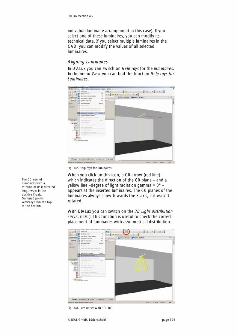
DIALux Version 4.7
DIAL GmbH, Lüdenscheid page 104
individual luminaire arrangement in this case). If you select one of these luminaires, you can modify its technical data. If you select multiple luminaires in the CAD, you can modify the values of all selected luminaires.
Aligning Luminaires In DIALux you can switch on Help rays for the luminaires. In the menu View you can find the function Help rays for Luminaires.
Fig. 145 Help rays for luminaires
When you click on this icon, a C0 arrow (red line) – which indicates the direction of the C0 plane – and a yellow line –degree of light radiation gamma = 0° – appears at the inserted luminaires. The C0 planes of the luminaires always show towards the X axis, if it wasn't rotated. With DIALux you can switch on the 3D Light distribution curve, (LDC). This function is useful to check the correct placement of luminaires with asymmetrical distribution.
Fig. 146 Luminaries with 3D LDC
The C0 level of luminaires with a rotation of 0° is directed lengthways in the positive X-axis. Gamma0 points vertically from the top to the bottom.
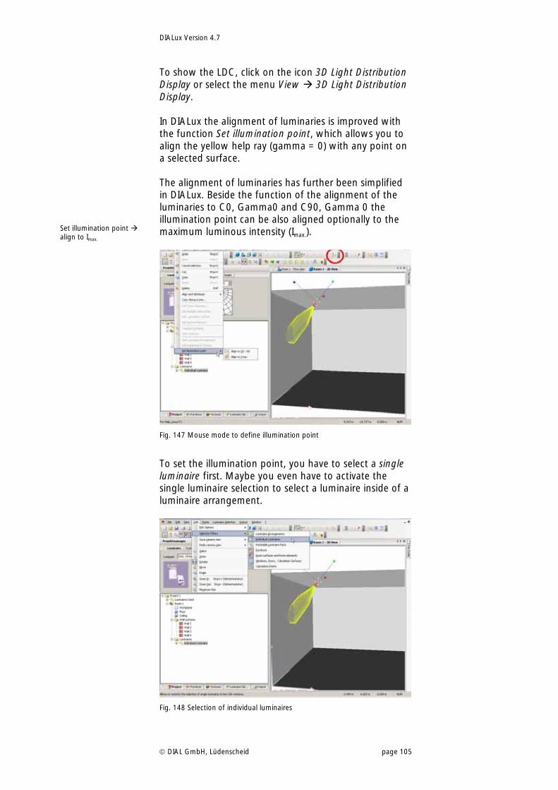
DIALux Version 4.7
DIAL GmbH, Lüdenscheid page 105
To show the LDC, click on the icon 3D Light Distribution Display or select the menu View 3D Light Distribution Display. In DIALux the alignment of luminaries is improved with the function Set illumination point, which allows you to align the yellow help ray (gamma = 0) with any point on a selected surface. The alignment of luminaries has further been simplified in DIALux. Beside the function of the alignment of the luminaries to C0, Gamma0 and C90, Gamma 0 the illumination point can be also aligned optionally to the maximum luminous intensity (Imax.).
Fig. 147 Mouse mode to define illumination point
To set the illumination point, you have to select a single luminaire first. Maybe you even have to activate the single luminaire selection to select a luminaire inside of a luminaire arrangement.
Fig. 148 Selection of individual luminaires
Set illumination point align to Imax.
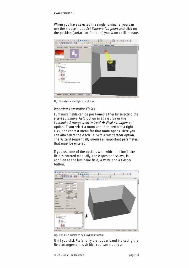
DIALux Version 4.7
DIAL GmbH, Lüdenscheid page 106
When you have selected the single luminaire, you can use the mouse mode Set illumination point and click on the position (surface or furniture) you want to illuminate.
Fig. 149 Align a spotlight to a picture
Inserting Luminaire Fields Luminaire fields can be positioned either by selecting the Insert Luminaire Field option in The Guide or the Luminaire Arrangement Wizard Field Arrangement option. If you select a room and then perform a right-click, the context menu for that room opens. Here you can also select the Insert Field Arrangement option. The Wizard sequentially queries all important parameters that must be entered. If you use one of the options with which the luminaire field is entered manually, the Inspector displays, in addition to the luminaire field, a Paste and a Cancel button.
Fig. 150 Insert luminaire fields without wizard
Until you click Paste, only the rubber band indicating the field arrangement is visible. You can modify all
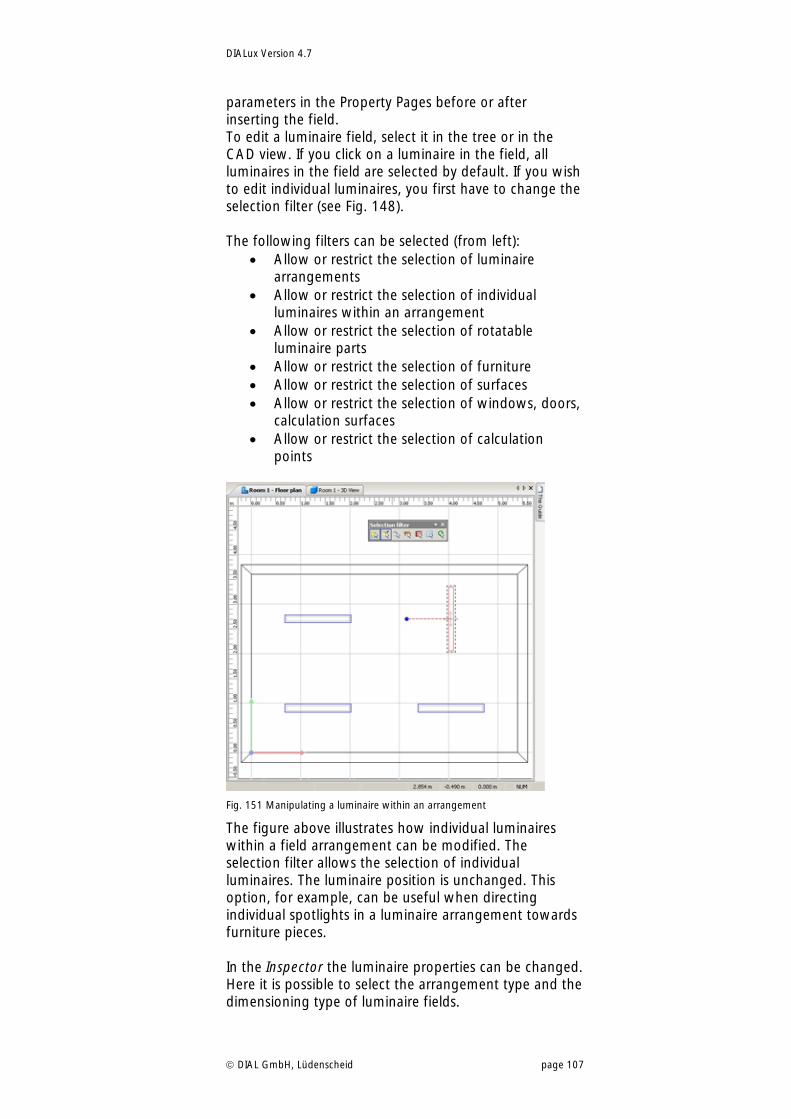
DIALux Version 4.7
DIAL GmbH, Lüdenscheid page 107
parameters in the Property Pages before or after inserting the field. To edit a luminaire field, select it in the tree or in the CAD view. If you click on a luminaire in the field, all luminaires in the field are selected by default. If you wish to edit individual luminaires, you first have to change the selection filter (see Fig. 148). The following filters can be selected (from left):
Allow or restrict the selection of luminaire arrangements
Allow or restrict the selection of individual luminaires within an arrangement
Allow or restrict the selection of rotatable luminaire parts
Allow or restrict the selection of furniture Allow or restrict the selection of surfaces Allow or restrict the selection of windows, doors,
calculation surfaces Allow or restrict the selection of calculation
points
Fig. 151 Manipulating a luminaire within an arrangement
The figure above illustrates how individual luminaires within a field arrangement can be modified. The selection filter allows the selection of individual luminaires. The luminaire position is unchanged. This option, for example, can be useful when directing individual spotlights in a luminaire arrangement towards furniture pieces. In the Inspector the luminaire properties can be changed. Here it is possible to select the arrangement type and the dimensioning type of luminaire fields.
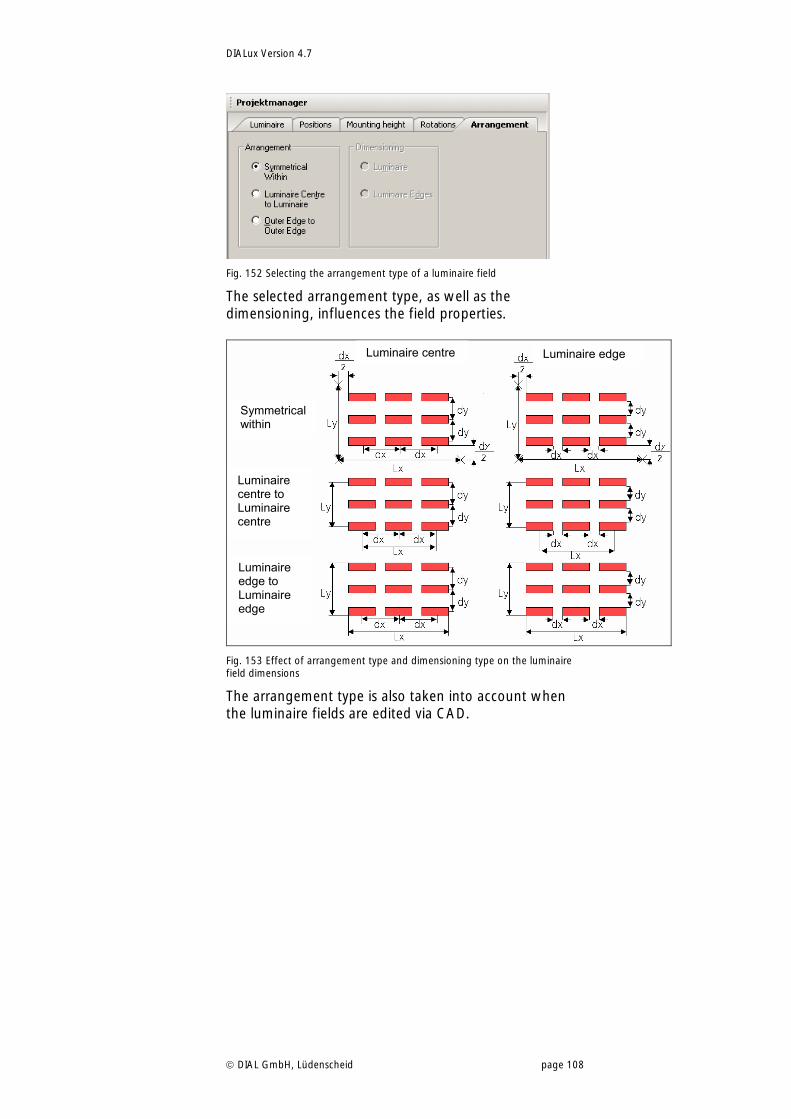
DIALux Version 4.7
DIAL GmbH, Lüdenscheid page 108
Fig. 152 Selecting the arrangement type of a luminaire field
The selected arrangement type, as well as the dimensioning, influences the field properties.
Fig. 153 Effect of arrangement type and dimensioning type on the luminaire field dimensions
The arrangement type is also taken into account when the luminaire fields are edited via CAD.
Luminaire centre Luminaire edge
Symmetrical within
Luminaire centre to Luminaire centre
Luminaire edge to Luminaire edge
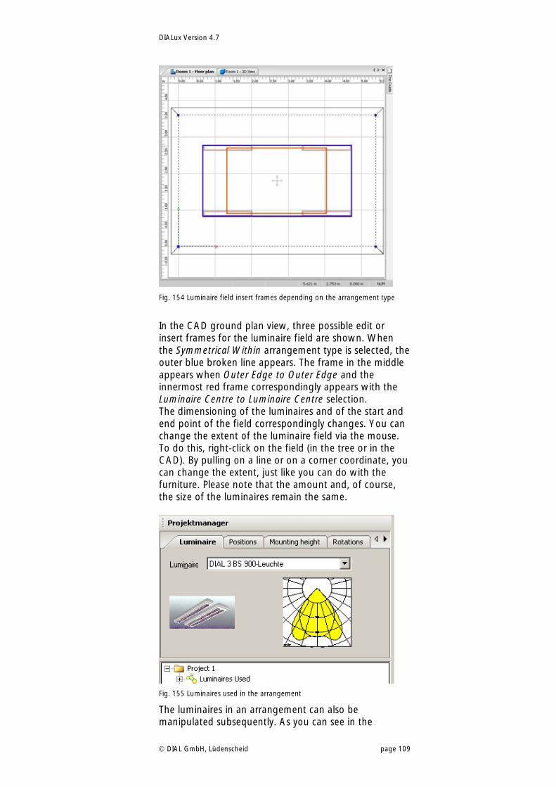
DIALux Version 4.7
DIAL GmbH, Lüdenscheid page 109
Fig. 154 Luminaire field insert frames depending on the arrangement type
In the CAD ground plan view, three possible edit or insert frames for the luminaire field are shown. When the Symmetrical Within arrangement type is selected, the outer blue broken line appears. The frame in the middle appears when Outer Edge to Outer Edge and the innermost red frame correspondingly appears with the Luminaire Centre to Luminaire Centre selection. The dimensioning of the luminaires and of the start and end point of the field correspondingly changes. You can change the extent of the luminaire field via the mouse. To do this, right-click on the field (in the tree or in the CAD). By pulling on a line or on a corner coordinate, you can change the extent, just like you can do with the furniture. Please note that the amount and, of course, the size of the luminaires remain the same.
Fig. 155 Luminaires used in the arrangement
The luminaires in an arrangement can also be manipulated subsequently. As you can see in the
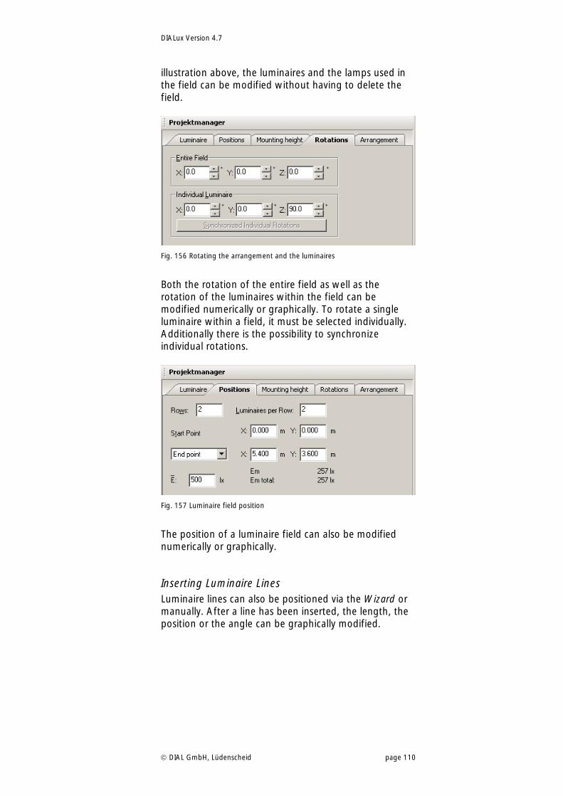
DIALux Version 4.7
DIAL GmbH, Lüdenscheid page 110
illustration above, the luminaires and the lamps used in the field can be modified without having to delete the field.
Fig. 156 Rotating the arrangement and the luminaires
Both the rotation of the entire field as well as the rotation of the luminaires within the field can be modified numerically or graphically. To rotate a single luminaire within a field, it must be selected individually. Additionally there is the possibility to synchronize individual rotations.
Fig. 157 Luminaire field position
The position of a luminaire field can also be modified numerically or graphically.
Inserting Luminaire Lines Luminaire lines can also be positioned via the Wizard or manually. After a line has been inserted, the length, the position or the angle can be graphically modified.
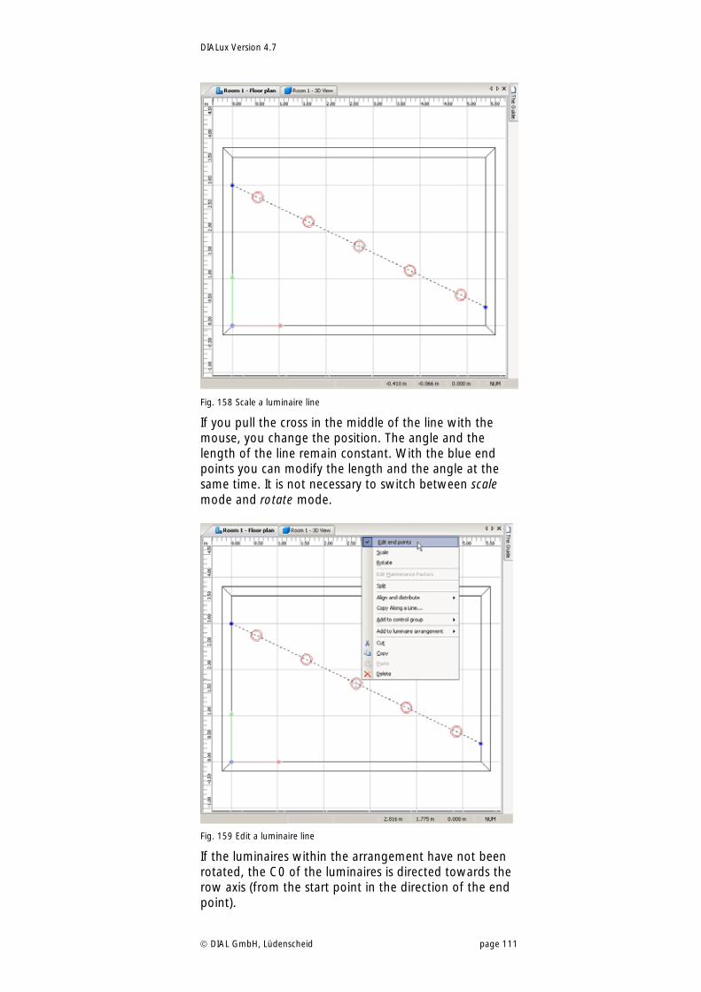
DIALux Version 4.7
DIAL GmbH, Lüdenscheid page 111
Fig. 158 Scale a luminaire line
If you pull the cross in the middle of the line with the mouse, you change the position. The angle and the length of the line remain constant. With the blue end points you can modify the length and the angle at the same time. It is not necessary to switch between scale mode and rotate mode.
Fig. 159 Edit a luminaire line
If the luminaires within the arrangement have not been rotated, the C0 of the luminaires is directed towards the row axis (from the start point in the direction of the end point).
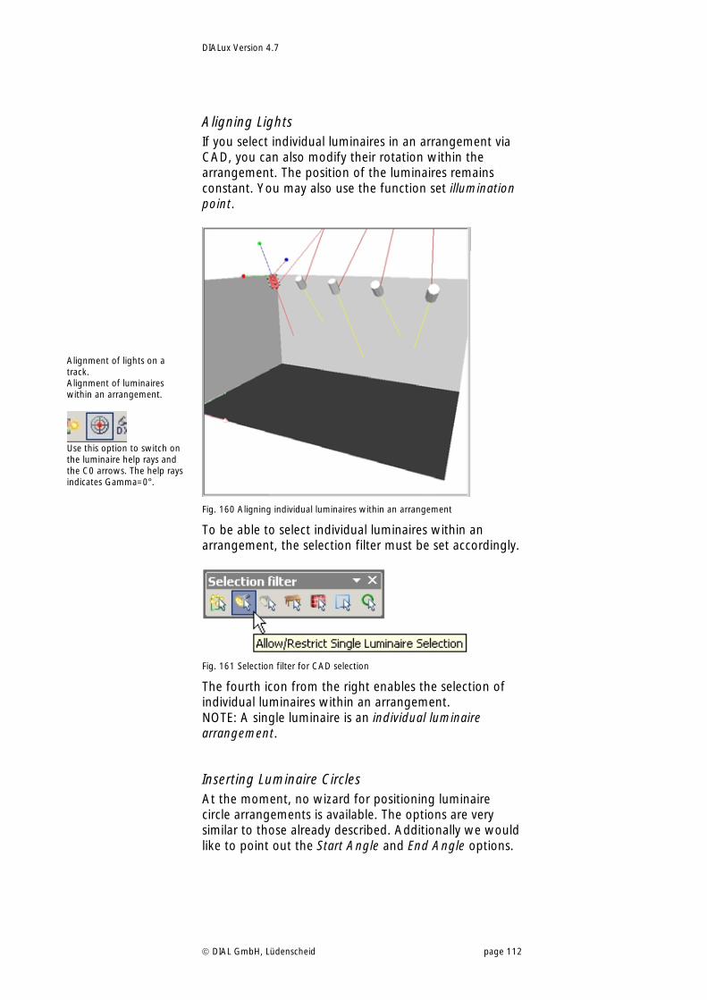
DIALux Version 4.7
DIAL GmbH, Lüdenscheid page 112
Aligning Lights If you select individual luminaires in an arrangement via CAD, you can also modify their rotation within the arrangement. The position of the luminaires remains constant. You may also use the function set illumination point.
Fig. 160 Aligning individual luminaires within an arrangement
To be able to select individual luminaires within an arrangement, the selection filter must be set accordingly.
Fig. 161 Selection filter for CAD selection
The fourth icon from the right enables the selection of individual luminaires within an arrangement. NOTE: A single luminaire is an individual luminaire arrangement.
Inserting Luminaire Circles At the moment, no wizard for positioning luminaire circle arrangements is available. The options are very similar to those already described. Additionally we would like to point out the Start Angle and End Angle options.
Alignment of lights on a track. Alignment of luminaires within an arrangement.
Use this option to switch on the luminaire help rays and the C0 arrows. The help rays indicates Gamma=0°.
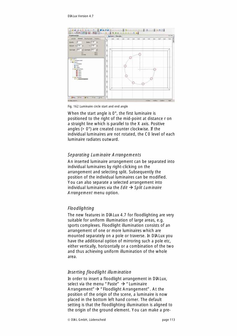
DIALux Version 4.7
DIAL GmbH, Lüdenscheid page 113
Fig. 162 Luminaire circle start and end angle
When the start angle is 0°, the first luminaire is positioned to the right of the mid-point at distance r on a straight line which is parallel to the X axis. Positive angles (> 0°) are created counter clockwise. If the individual luminaires are not rotated, the C0 level of each luminaire radiates outward.
Separating Luminaire Arrangements An inserted luminaire arrangement can be separated into individual luminaires by right-clicking on the arrangement and selecting split. Subsequently the position of the individual luminaires can be modified. You can also separate a selected arrangement into individual luminaires via the Edit Split Luminaire Arrangement menu option.
Floodlighting The new features in DIALux 4.7 for floodlighting are very suitable for uniform illumination of large areas, e.g. sports complexes. Floodlight illumination consists of an arrangement of one or more luminaires which are mounted separately on a pole or traverse. In DIALux you have the additional option of mirroring such a pole etc, either vertically, horizontally or a combination of the two and thus achieving uniform illumination of the whole area.
Inserting floodlight illumination In order to insert a floodlight arrangement in DIALux, select via the menu “Paste” “Luminaire Arrangement” “Floodlight Arrangement”. At the position of the origin of the scene, a luminaire is now placed in the bottom left hand corner. The default setting is that the floodlighting illumination is aligned to the origin of the ground element. You can make a pre-
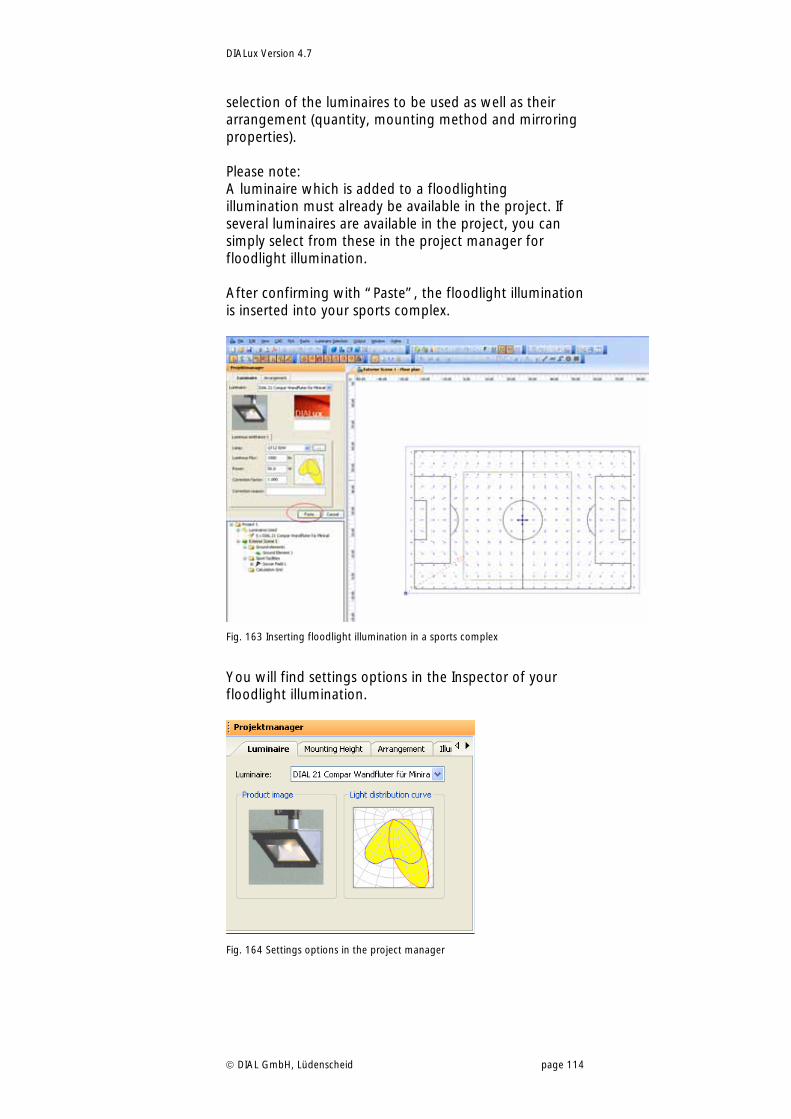
DIALux Version 4.7
DIAL GmbH, Lüdenscheid page 114
selection of the luminaires to be used as well as their arrangement (quantity, mounting method and mirroring properties). Please note: A luminaire which is added to a floodlighting illumination must already be available in the project. If several luminaires are available in the project, you can simply select from these in the project manager for floodlight illumination. After confirming with “Paste”, the floodlight illumination is inserted into your sports complex.
Fig. 163 Inserting floodlight illumination in a sports complex
You will find settings options in the Inspector of your floodlight illumination.
Fig. 164 Settings options in the project manager
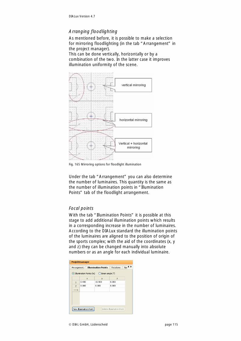
DIALux Version 4.7
DIAL GmbH, Lüdenscheid page 115
Arranging floodlighting As mentioned before, it is possible to make a selection for mirroring floodlighting (in the tab “Arrangement” in the project manager). This can be done vertically, horizontally or by a combination of the two. In the latter case it improves illumination uniformity of the scene.
Fig. 165 Mirroring options for floodlight illumination
Under the tab “Arrangement” you can also determine the number of luminaires. This quantity is the same as the number of illumination points in “Illumination Points” tab of the floodlight arrangement.
Focal points With the tab “Illumination Points” it is possible at this stage to add additional illumination points which results in a corresponding increase in the number of luminaires. According to the DIALux standard the illumination points of the luminaires are aligned to the position of origin of the sports complex; with the aid of the coordinates (x, y and z) they can be changed manually into absolute numbers or as an angle for each individual luminaire.
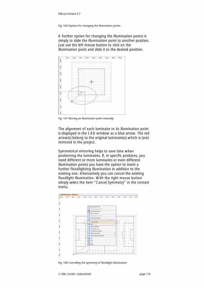
DIALux Version 4.7
DIAL GmbH, Lüdenscheid page 116
Fig. 166 Options for changing the illumination points
A further option for changing the illumination points is simply to slide the illumination point to another position. Just use the left mouse button to click on the illumination point and slide it to the desired position.
Fig. 167 Moving an illumination point manually
The alignment of each luminaire to its illumination point is displayed in the CAD window as a blue arrow. The red arrow(s) belong to the original luminaire(s) which is (are) mirrored in the project. Symmetrical mirroring helps to save time when positioning the luminaires. If, in specific positions, you need different or more luminaires or even different illumination points you have the option to insert a further floodlighting illumination in addition to the existing one. Alternatively you can cancel the existing floodlight illumination. With the right mouse button simply select the item “Cancel Symmetry” in the context menu.
Fig. 168 Cancelling the symmetry of floodlight illumination
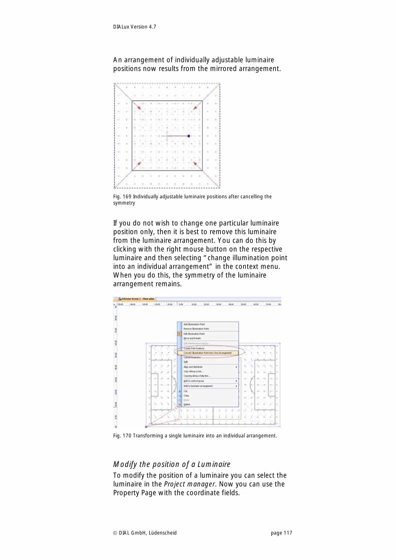
DIALux Version 4.7
DIAL GmbH, Lüdenscheid page 117
An arrangement of individually adjustable luminaire positions now results from the mirrored arrangement.
Fig. 169 Individually adjustable luminaire positions after cancelling the symmetry
If you do not wish to change one particular luminaire position only, then it is best to remove this luminaire from the luminaire arrangement. You can do this by clicking with the right mouse button on the respective luminaire and then selecting “change illumination point into an individual arrangement” in the context menu. When you do this, the symmetry of the luminaire arrangement remains.
Fig. 170 Transforming a single luminaire into an individual arrangement.
Modify the position of a Luminaire To modify the position of a luminaire you can select the luminaire in the Project manager. Now you can use the Property Page with the coordinate fields.
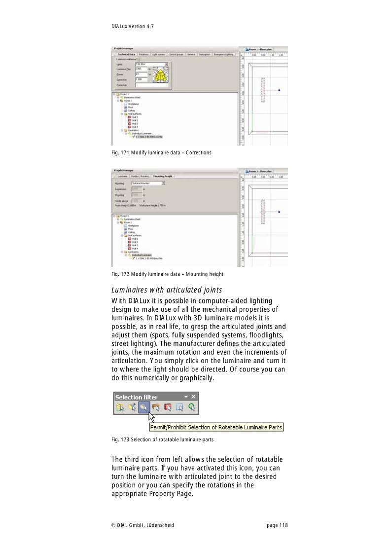
DIALux Version 4.7
DIAL GmbH, Lüdenscheid page 118
Fig. 171 Modify luminaire data – Corrections
Fig. 172 Modify luminaire data – Mounting height
Luminaires with articulated joints With DIALux it is possible in computer-aided lighting design to make use of all the mechanical properties of luminaires. In DIALux with 3D luminaire models it is possible, as in real life, to grasp the articulated joints and adjust them (spots, fully suspended systems, floodlights, street lighting). The manufacturer defines the articulated joints, the maximum rotation and even the increments of articulation. You simply click on the luminaire and turn it to where the light should be directed. Of course you can do this numerically or graphically.
Fig. 173 Selection of rotatable luminaire parts
The third icon from left allows the selection of rotatable luminaire parts. If you have activated this icon, you can turn the luminaire with articulated joint to the desired position or you can specify the rotations in the appropriate Property Page.
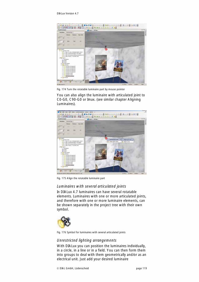
DIALux Version 4.7
DIAL GmbH, Lüdenscheid page 119
Fig. 174 Turn the rotatable luminaire part by mouse pointer
You can also align the luminaire with articulated joint to C0-G0, C90-G0 or Imax. (see similar chapter Aligning Luminaires).
Fig. 175 Align the rotatable luminaire part
Luminaires with several articulated joints In DIALux 4.7 luminaires can have several rotatable elements. Luminaires with one or more articulated joints, and therefore with one or more luminaire elements, can be shown separately in the project tree with their own symbol.
Fig. 176 Symbol for luminaires with several articulated joints
Unrestricted lighting arrangements With DIALux you can position the luminaires individually, in a circle, in a line or in a field. You can then form them into groups to deal with them geometrically and/or as an electrical unit. Just add your desired luminaire
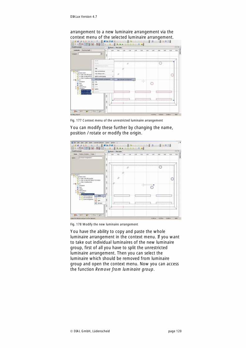
DIALux Version 4.7
DIAL GmbH, Lüdenscheid page 120
arrangement to a new luminaire arrangement via the context menu of the selected luminaire arrangement.
Fig. 177 Context menu of the unrestricted luminaire arrangement
You can modify these further by changing the name, position / rotate or modify the origin.
Fig. 178 Modify the new luminaire arrangement
You have the ability to copy and paste the whole luminaire arrangement in the context menu. If you want to take out individual luminaires of the new luminaire group, first of all you have to split the unrestricted luminaire arrangement. Then you can select the luminaire which should be removed from luminaire group and open the context menu. Now you can access the function Remove from luminaire group.
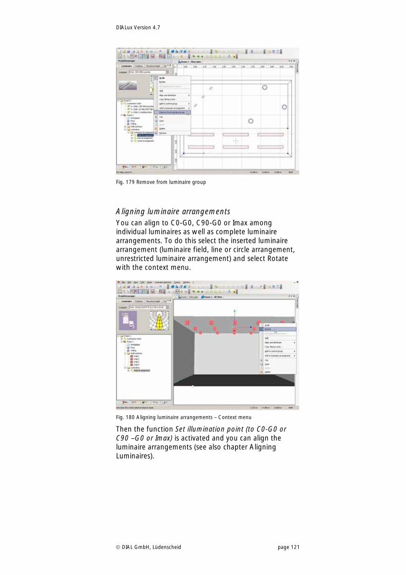
DIALux Version 4.7
DIAL GmbH, Lüdenscheid page 121
Fig. 179 Remove from luminaire group
Aligning luminaire arrangements You can align to C0-G0, C90-G0 or Imax among individual luminaires as well as complete luminaire arrangements. To do this select the inserted luminaire arrangement (luminaire field, line or circle arrangement, unrestricted luminaire arrangement) and select Rotate with the context menu.
Fig. 180 Aligning luminaire arrangements – Context menu
Then the function Set illumination point (to C0-G0 or C90 –G0 or Imax) is activated and you can align the luminaire arrangements (see also chapter Aligning Luminaires).
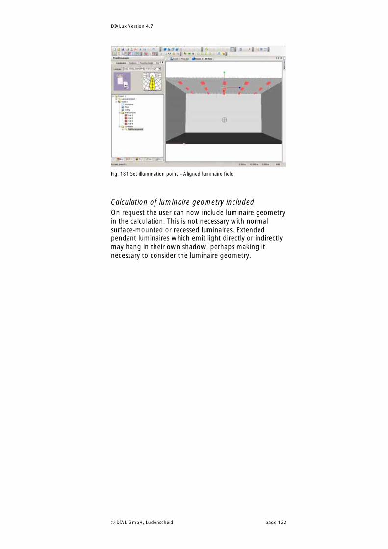
DIALux Version 4.7
DIAL GmbH, Lüdenscheid page 122
Fig. 181 Set illumination point – Aligned luminaire field
Calculation of luminaire geometry included On request the user can now include luminaire geometry in the calculation. This is not necessary with normal surface-mounted or recessed luminaires. Extended pendant luminaires which emit light directly or indirectly may hang in their own shadow, perhaps making it necessary to consider the luminaire geometry.
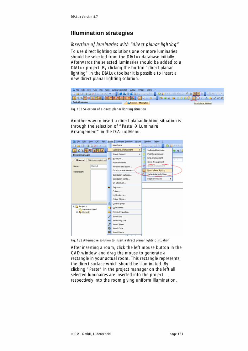
DIALux Version 4.7
DIAL GmbH, Lüdenscheid page 123
Illumination strategies
Insertion of luminaries with “direct planar lighting” To use direct lighting solutions one or more luminaries should be selected from the DIALux database initially. Afterwards the selected luminaries should be added to a DIALux project. By clicking the button “direct planar lighting” in the DIALux toolbar it is possible to insert a new direct planar lighting solution.
Fig. 182 Selection of a direct planar lighting situation
Another way to insert a direct planar lighting situation is through the selection of “Paste Luminaire Arrangement” in the DIALux Menu.
Fig. 183 Alternative solution to insert a direct planar lighting situation
After inserting a room, click the left mouse button in the CAD window and drag the mouse to generate a rectangle in your actual room. This rectangle represents the direct surface which should be illuminated. By clicking “Paste” in the project manager on the left all selected luminaires are inserted into the project respectively into the room giving uniform illumination.
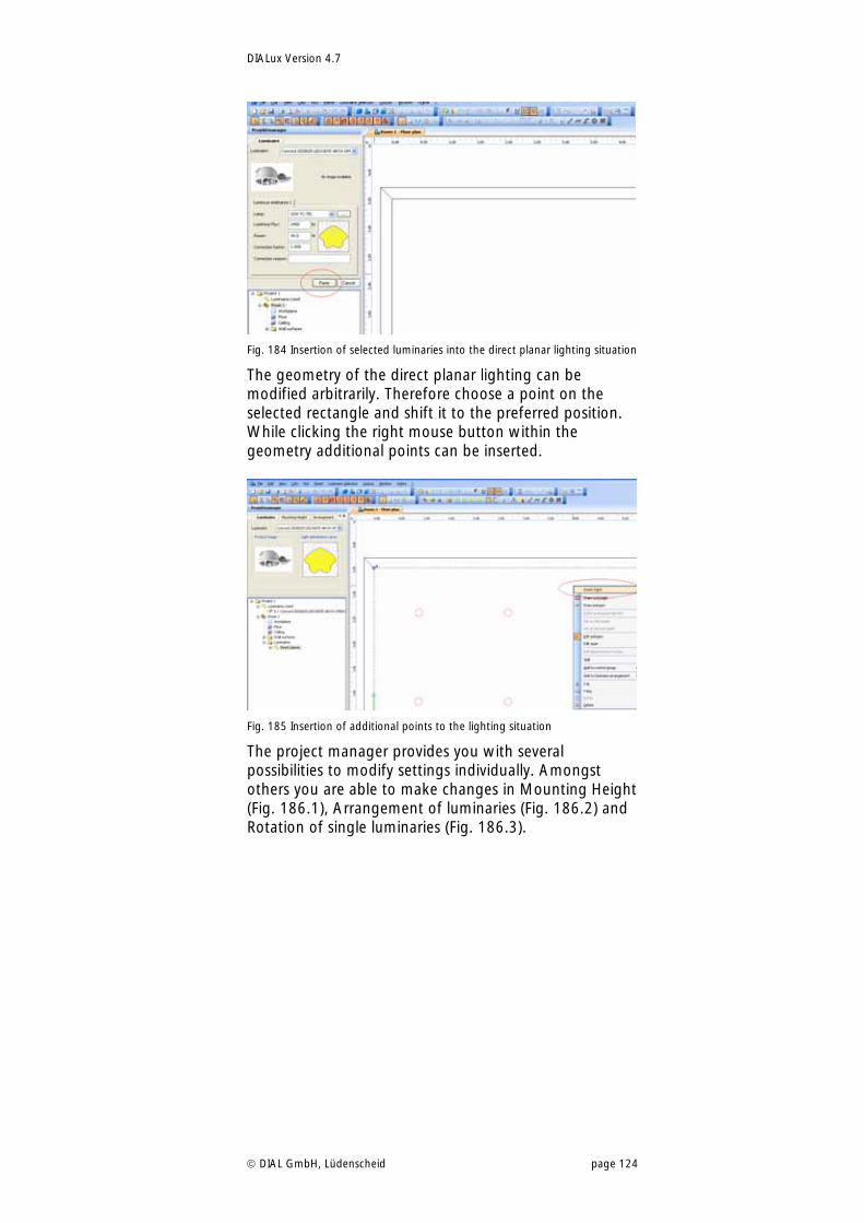
DIALux Version 4.7
DIAL GmbH, Lüdenscheid page 124
Fig. 184 Insertion of selected luminaries into the direct planar lighting situation
The geometry of the direct planar lighting can be modified arbitrarily. Therefore choose a point on the selected rectangle and shift it to the preferred position. While clicking the right mouse button within the geometry additional points can be inserted.
Fig. 185 Insertion of additional points to the lighting situation
The project manager provides you with several possibilities to modify settings individually. Amongst others you are able to make changes in Mounting Height (Fig. 186.1), Arrangement of luminaries (Fig. 186.2) and Rotation of single luminaries (Fig. 186.3).
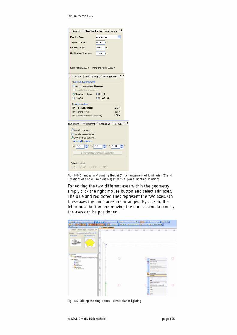
DIALux Version 4.7
DIAL GmbH, Lüdenscheid page 125
Fig. 186 Changes in Mounting Height (1), Arrangement of luminaries (2) and Rotations of single luminaries (3) at vertical planar lighting solutions
For editing the two different axes within the geometry simply click the right mouse button and select Edit axes. The blue and red doted lines represent the two axes. On these axes the luminaries are arranged. By clicking the left mouse button and moving the mouse simultaneously the axes can be positioned.
Fig. 187 Editing the single axes – direct planar lighting
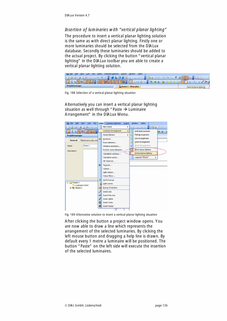
DIALux Version 4.7
DIAL GmbH, Lüdenscheid page 126
Insertion of luminaries with “vertical planar lighting” The procedure to insert a vertical planar lighting solution is the same as with direct planar lighting. Firstly one or more luminaries should be selected from the DIALux database. Secondly these luminaries should be added to the actual project. By clicking the button “vertical planar lighting” in the DIALux toolbar you are able to create a vertical planar lighting solution.
Fig. 188 Selection of a vertical planar lighting situation
Alternatively you can insert a vertical planar lighting situation as well through “Paste Luminaire Arrangement” in the DIALux Menu.
Fig. 189 Alternative solution to insert a vertical planar lighting situation
After clicking the button a project window opens. You are now able to draw a line which represents the arrangement of the selected luminaries. By clicking the left mouse button and dragging a help line is drawn. By default every 1 metre a luminaire will be positioned. The button “Paste” on the left side will execute the insertion of the selected luminaires.
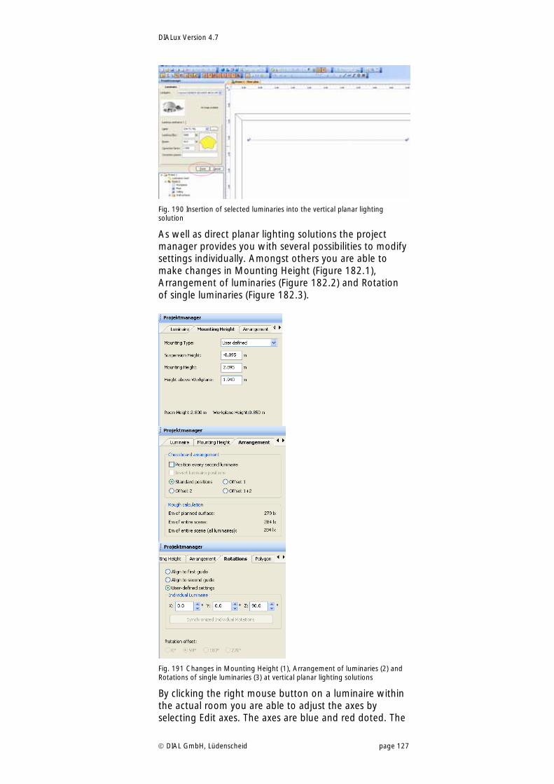
DIALux Version 4.7
DIAL GmbH, Lüdenscheid page 127
Fig. 190 Insertion of selected luminaries into the vertical planar lighting solution
As well as direct planar lighting solutions the project manager provides you with several possibilities to modify settings individually. Amongst others you are able to make changes in Mounting Height (Figure 182.1), Arrangement of luminaries (Figure 182.2) and Rotation of single luminaries (Figure 182.3).
Fig. 191 Changes in Mounting Height (1), Arrangement of luminaries (2) and Rotations of single luminaries (3) at vertical planar lighting solutions
By clicking the right mouse button on a luminaire within the actual room you are able to adjust the axes by selecting Edit axes. The axes are blue and red doted. The
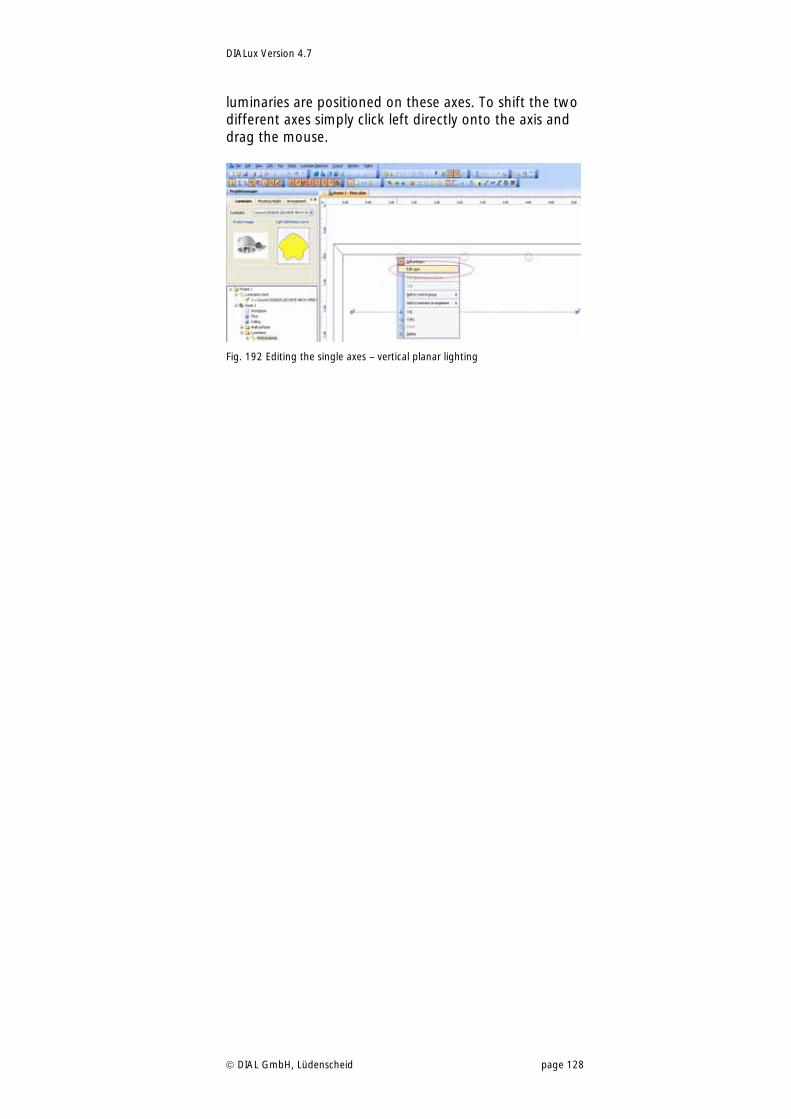
DIALux Version 4.7
DIAL GmbH, Lüdenscheid page 128
luminaries are positioned on these axes. To shift the two different axes simply click left directly onto the axis and drag the mouse.
Fig. 192 Editing the single axes – vertical planar lighting
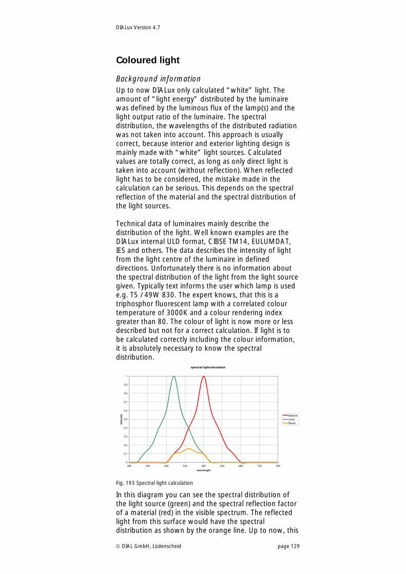
DIALux Version 4.7
DIAL GmbH, Lüdenscheid page 129
Coloured light
Background information Up to now DIALux only calculated “white” light. The amount of “light energy” distributed by the luminaire was defined by the luminous flux of the lamp(s) and the light output ratio of the luminaire. The spectral distribution, the wavelengths of the distributed radiation was not taken into account. This approach is usually correct, because interior and exterior lighting design is mainly made with “white” light sources. Calculated values are totally correct, as long as only direct light is taken into account (without reflection). When reflected light has to be considered, the mistake made in the calculation can be serious. This depends on the spectral reflection of the material and the spectral distribution of the light sources. Technical data of luminaires mainly describe the distribution of the light. Well known examples are the DIALux internal ULD format, CIBSE TM14, EULUMDAT, IES and others. The data describes the intensity of light from the light centre of the luminaire in defined directions. Unfortunately there is no information about the spectral distribution of the light from the light source given. Typically text informs the user which lamp is used e.g. T5 / 49W 830. The expert knows, that this is a triphosphor fluorescent lamp with a correlated colour temperature of 3000K and a colour rendering index greater than 80. The colour of light is now more or less described but not for a correct calculation. If light is to be calculated correctly including the colour information, it is absolutely necessary to know the spectral distribution.
spectral lightcalculation
0
0,1
0,2
0,3
0,4
0,5
0,6
0,7
0,8
0,9
1
380 430 480 530 580 630 680 730 780
wavelength
inte
nsi
ty Material
Lamp
Result
Fig. 193 Spectral light calculation
In this diagram you can see the spectral distribution of the light source (green) and the spectral reflection factor of a material (red) in the visible spectrum. The reflected light from this surface would have the spectral distribution as shown by the orange line. Up to now, this
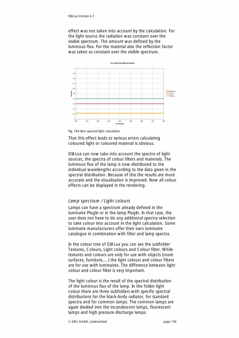
DIALux Version 4.7
DIAL GmbH, Lüdenscheid page 130
effect was not taken into account by the calculation. For the light source the radiation was constant over the visible spectrum. The amount was defined by the luminous flux. For the material also the reflection factor was taken as constant over the visible spectrum.
non spectral lightcalculation
0
0,1
0,2
0,3
0,4
0,5
0,6
0,7
0,8
0,9
1
380 430 480 530 580 630 680 730 780
wavelength
inte
nsi
ty Material
Lamp
Result
Fig. 194 Non spectral light calculation
That this effect leads to serious errors calculating coloured light or coloured material is obvious. DIALux can now take into account the spectra of light sources, the spectra of colour filters and materials. The luminous flux of the lamp is now distributed to the individual wavelengths according to the data given in the spectral distribution. Because of this the results are more accurate and the visualisation is improved. Now all colour effects can be displayed in the rendering.
Lamp spectrum / Light colours Lamps can have a spectrum already defined in the luminaire PlugIn or in the lamp PlugIn. In that case, the user does not have to do any additional spectra selection to take colour into account in the light calculation. Some luminaire manufacturers offer their own luminaire catalogue in combination with filter and lamp spectra. In the colour tree of DIALux you can see the subfolder Textures, Colours, Light colours and Colour filter. While textures and colours are only for use with objects (room surfaces, furniture,…) the light colours and colour filters are for use with luminaires. The difference between light colour and colour filter is very important. The light colour is the result of the spectral distribution of the luminous flux of the lamp. In the folder light colour there are three subfolders with specific spectral distributions for the black-body radiator, for standard spectra and for common lamps. The common lamps are again divided into the incandescent lamps, fluorescent lamps and high pressure discharge lamps.
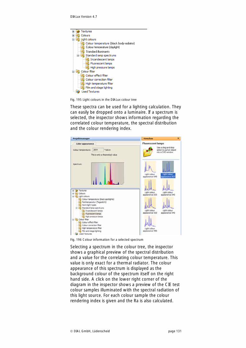
DIALux Version 4.7
DIAL GmbH, Lüdenscheid page 131
Fig. 195 Light colours in the DIALux colour tree
These spectra can be used for a lighting calculation. They can easily be dropped onto a luminaire. If a spectrum is selected, the inspector shows information regarding the correlated colour temperature, the spectral distribution and the colour rendering index.
Fig. 196 Colour information for a selected spectrum
Selecting a spectrum in the colour tree, the inspector shows a graphical preview of the spectral distribution and a value for the correlating colour temperature. This value is only exact for a thermal radiator. The colour appearance of this spectrum is displayed as the background colour of the spectrum itself on the right hand side. A click on the lower right corner of the diagram in the inspector shows a preview of the CIE test colour samples illuminated with the spectral radiation of this light source. For each colour sample the colour rendering index is given and the Ra is also calculated.
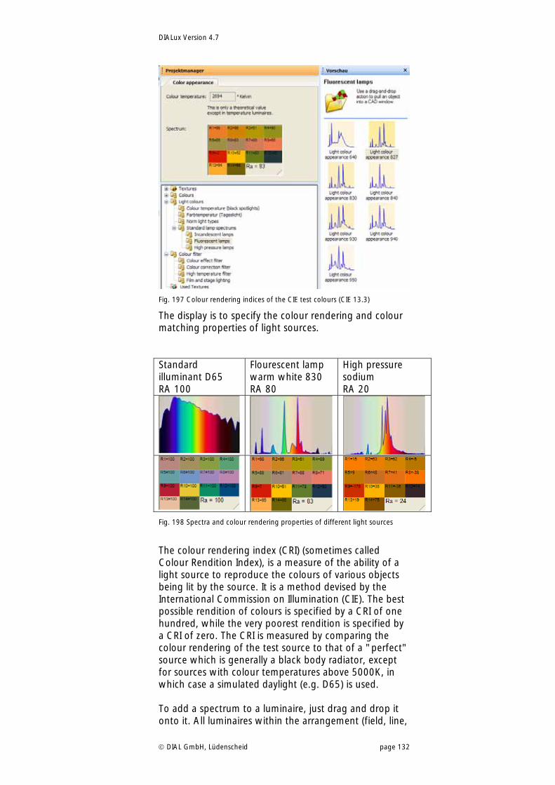
DIALux Version 4.7
DIAL GmbH, Lüdenscheid page 132
Fig. 197 Colour rendering indices of the CIE test colours (CIE 13.3)
The display is to specify the colour rendering and colour matching properties of light sources. Standard illuminant D65 RA 100
Flourescent lamp warm white 830 RA 80
High pressure sodium RA 20
Fig. 198 Spectra and colour rendering properties of different light sources
The colour rendering index (CRI) (sometimes called Colour Rendition Index), is a measure of the ability of a light source to reproduce the colours of various objects being lit by the source. It is a method devised by the International Commission on Illumination (CIE). The best possible rendition of colours is specified by a CRI of one hundred, while the very poorest rendition is specified by a CRI of zero. The CRI is measured by comparing the colour rendering of the test source to that of a "perfect" source which is generally a black body radiator, except for sources with colour temperatures above 5000K, in which case a simulated daylight (e.g. D65) is used. To add a spectrum to a luminaire, just drag and drop it onto it. All luminaires within the arrangement (field, line,
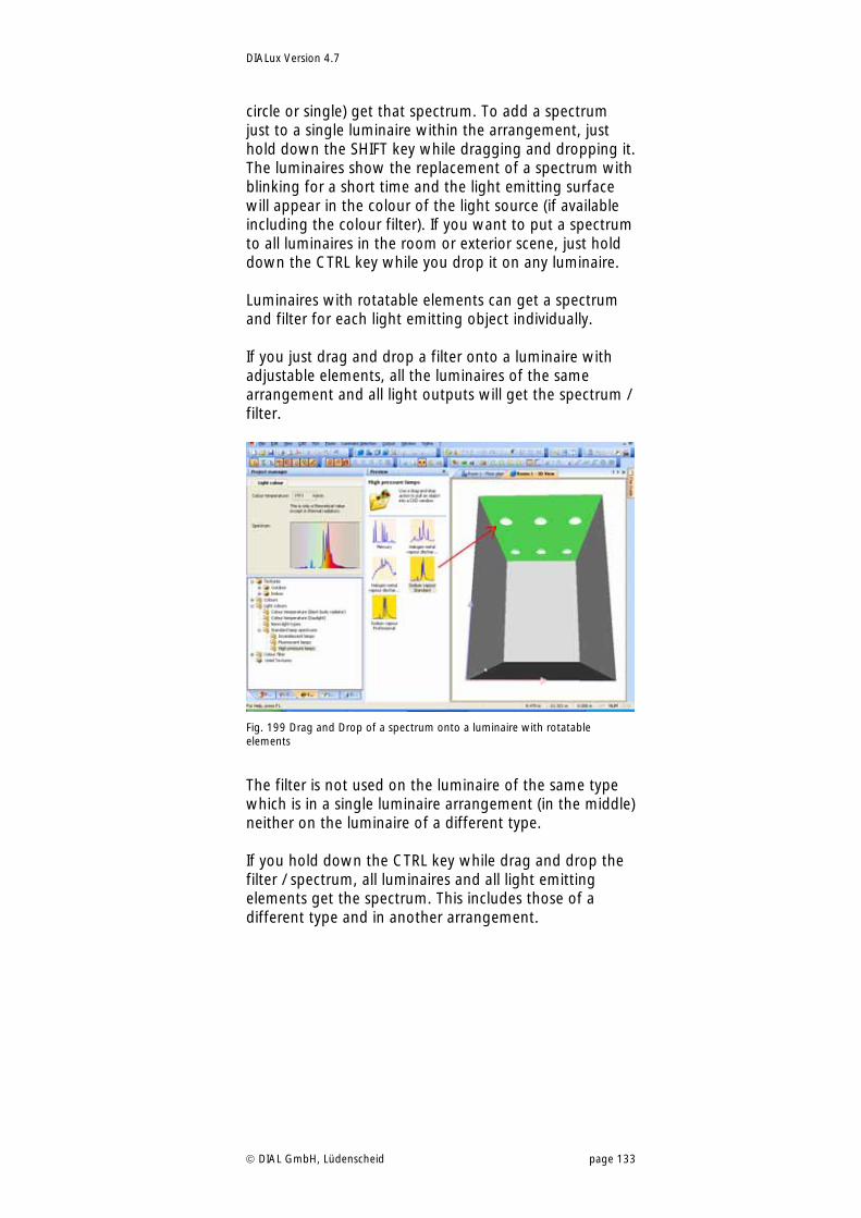
DIALux Version 4.7
DIAL GmbH, Lüdenscheid page 133
circle or single) get that spectrum. To add a spectrum just to a single luminaire within the arrangement, just hold down the SHIFT key while dragging and dropping it. The luminaires show the replacement of a spectrum with blinking for a short time and the light emitting surface will appear in the colour of the light source (if available including the colour filter). If you want to put a spectrum to all luminaires in the room or exterior scene, just hold down the CTRL key while you drop it on any luminaire. Luminaires with rotatable elements can get a spectrum and filter for each light emitting object individually. If you just drag and drop a filter onto a luminaire with adjustable elements, all the luminaires of the same arrangement and all light outputs will get the spectrum / filter.
Fig. 199 Drag and Drop of a spectrum onto a luminaire with rotatable elements
The filter is not used on the luminaire of the same type which is in a single luminaire arrangement (in the middle) neither on the luminaire of a different type. If you hold down the CTRL key while drag and drop the filter / spectrum, all luminaires and all light emitting elements get the spectrum. This includes those of a different type and in another arrangement.
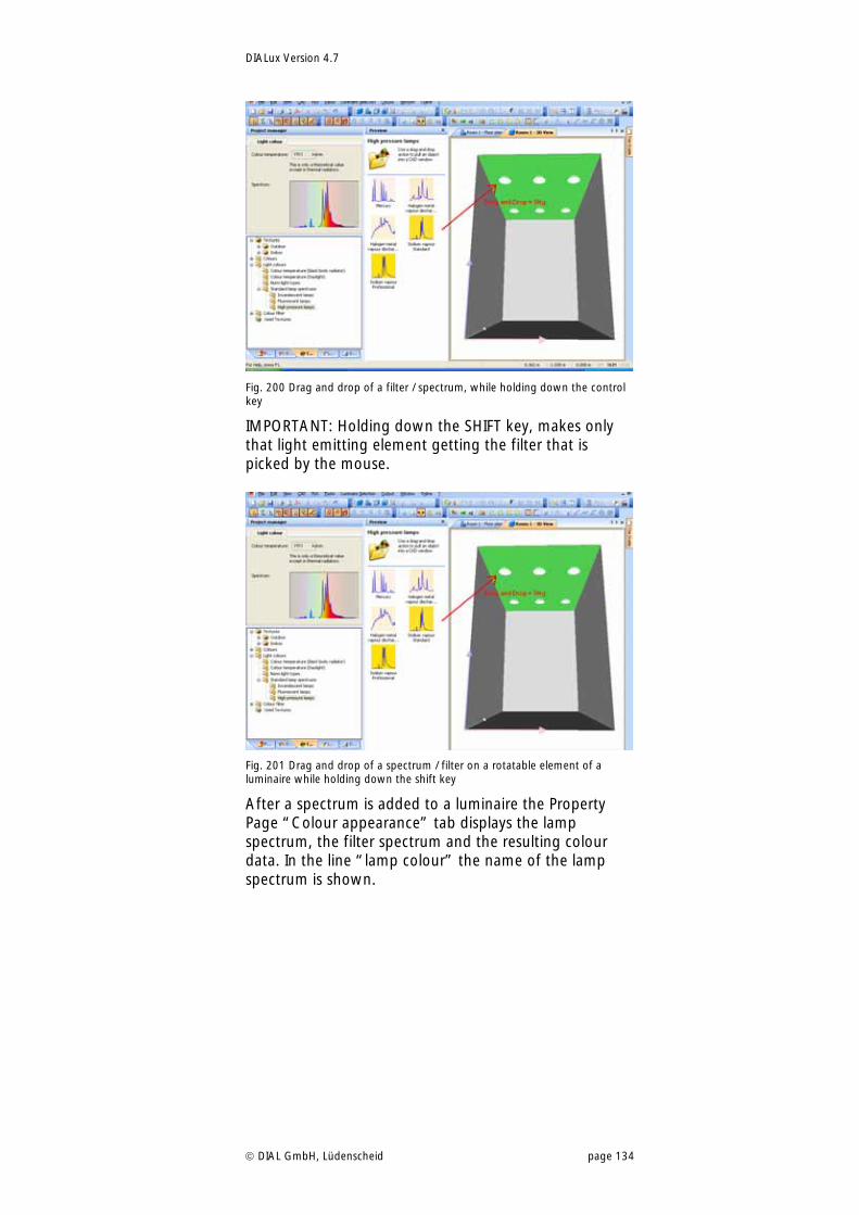
DIALux Version 4.7
DIAL GmbH, Lüdenscheid page 134
Fig. 200 Drag and drop of a filter / spectrum, while holding down the control key
IMPORTANT: Holding down the SHIFT key, makes only that light emitting element getting the filter that is picked by the mouse.
Fig. 201 Drag and drop of a spectrum / filter on a rotatable element of a luminaire while holding down the shift key
After a spectrum is added to a luminaire the Property Page “Colour appearance” tab displays the lamp spectrum, the filter spectrum and the resulting colour data. In the line “lamp colour” the name of the lamp spectrum is shown.
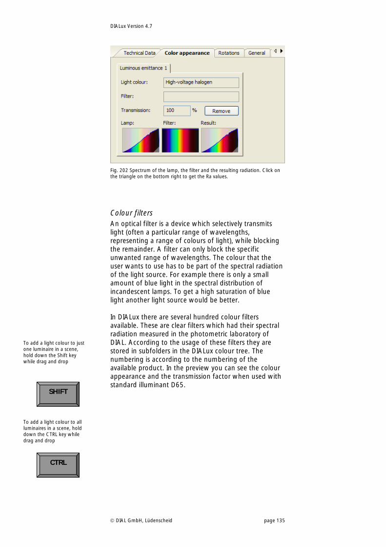
DIALux Version 4.7
DIAL GmbH, Lüdenscheid page 135
Fig. 202 Spectrum of the lamp, the filter and the resulting radiation. Click on the triangle on the bottom right to get the Ra values.
Colour filters An optical filter is a device which selectively transmits light (often a particular range of wavelengths, representing a range of colours of light), while blocking the remainder. A filter can only block the specific unwanted range of wavelengths. The colour that the user wants to use has to be part of the spectral radiation of the light source. For example there is only a small amount of blue light in the spectral distribution of incandescent lamps. To get a high saturation of blue light another light source would be better. In DIALux there are several hundred colour filters available. These are clear filters which had their spectral radiation measured in the photometric laboratory of DIAL. According to the usage of these filters they are stored in subfolders in the DIALux colour tree. The numbering is according to the numbering of the available product. In the preview you can see the colour appearance and the transmission factor when used with standard illuminant D65.
To add a light colour to just one luminaire in a scene, hold down the Shift key while drag and drop
To add a light colour to all luminaires in a scene, hold down the CTRL key while drag and drop CTRL
SHIFT
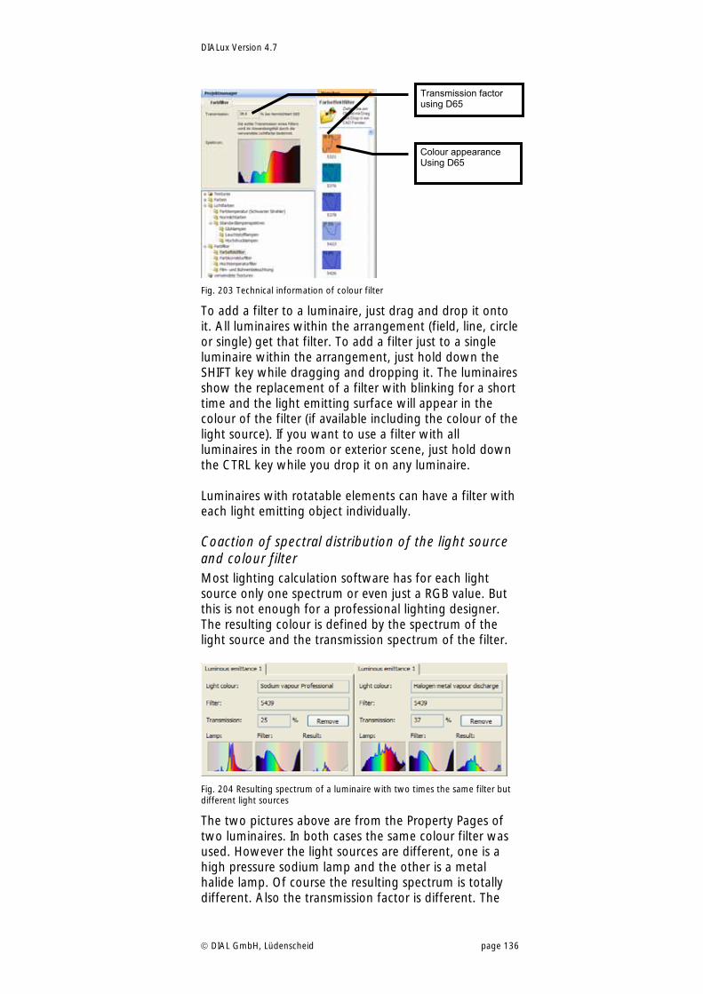
DIALux Version 4.7
DIAL GmbH, Lüdenscheid page 136
Fig. 203 Technical information of colour filter
To add a filter to a luminaire, just drag and drop it onto it. All luminaires within the arrangement (field, line, circle or single) get that filter. To add a filter just to a single luminaire within the arrangement, just hold down the SHIFT key while dragging and dropping it. The luminaires show the replacement of a filter with blinking for a short time and the light emitting surface will appear in the colour of the filter (if available including the colour of the light source). If you want to use a filter with all luminaires in the room or exterior scene, just hold down the CTRL key while you drop it on any luminaire. Luminaires with rotatable elements can have a filter with each light emitting object individually.
Coaction of spectral distribution of the light source and colour filter Most lighting calculation software has for each light source only one spectrum or even just a RGB value. But this is not enough for a professional lighting designer. The resulting colour is defined by the spectrum of the light source and the transmission spectrum of the filter.
Fig. 204 Resulting spectrum of a luminaire with two times the same filter but different light sources
The two pictures above are from the Property Pages of two luminaires. In both cases the same colour filter was used. However the light sources are different, one is a high pressure sodium lamp and the other is a metal halide lamp. Of course the resulting spectrum is totally different. Also the transmission factor is different. The
Colour appearance Using D65
Transmission factor using D65
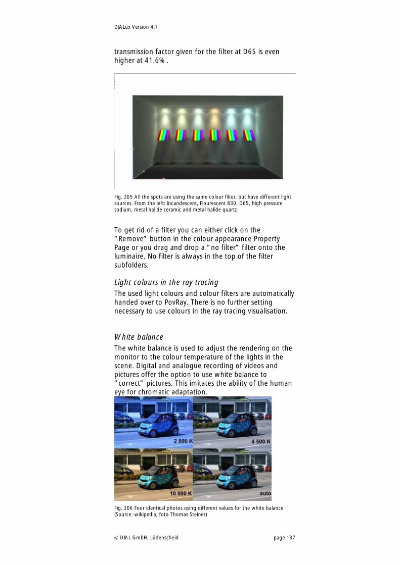
DIALux Version 4.7
DIAL GmbH, Lüdenscheid page 137
transmission factor given for the filter at D65 is even higher at 41.6%.
Fig. 205 All the spots are using the same colour filter, but have different light sources. From the left: Incandescent, Flourescent 830, D65, high pressure sodium, metal halide ceramic and metal halide quartz
To get rid of a filter you can either click on the “Remove” button in the colour appearance Property Page or you drag and drop a “no filter” filter onto the luminaire. No filter is always in the top of the filter subfolders.
Light colours in the ray tracing The used light colours and colour filters are automatically handed over to PovRay. There is no further setting necessary to use colours in the ray tracing visualisation.
White balance The white balance is used to adjust the rendering on the monitor to the colour temperature of the lights in the scene. Digital and analogue recording of videos and pictures offer the option to use white balance to “correct” pictures. This imitates the ability of the human eye for chromatic adaptation.
Fig. 206 Four identical photos using different values for the white balance (Source: wikipedia, foto Thomas Steiner)
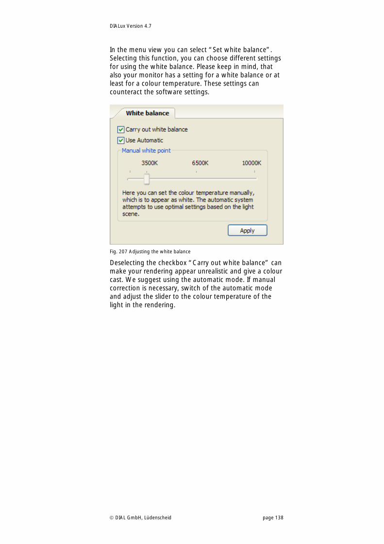
DIALux Version 4.7
DIAL GmbH, Lüdenscheid page 138
In the menu view you can select “Set white balance”. Selecting this function, you can choose different settings for using the white balance. Please keep in mind, that also your monitor has a setting for a white balance or at least for a colour temperature. These settings can counteract the software settings.
Fig. 207 Adjusting the white balance
Deselecting the checkbox “Carry out white balance” can make your rendering appear unrealistic and give a colour cast. We suggest using the automatic mode. If manual correction is necessary, switch of the automatic mode and adjust the slider to the colour temperature of the light in the rendering.
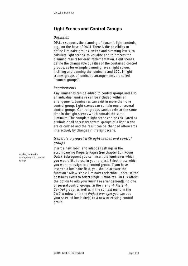
DIALux Version 4.7
DIAL GmbH, Lüdenscheid page 139
Light Scenes and Control Groups
Definition DIALux supports the planning of dynamic light controls, e.g., on the base of DALI. There is the possibility to define luminaire groups, switch and dimming levels, to calculate light scenes, to visualize and to process the planning results for easy implementation. Light scenes define the changeable qualities of the contained control groups, as for example dimming levels, light colour, inclining and panning the luminaire and LDC. In light scenes groups of luminaire arrangements are called "control groups".
Requirements Any luminaries can be added to control groups and also an individual luminaire can be included within an arrangement. Luminaires can exist in more than one control group. Light scenes can contain one or several control groups. Control groups cannot exist at the same time in the light scenes which contain the same luminaire. The complete light scene can be calculated as a whole or all necessary control groups of a light scene are calculated and the result can be changed afterwards interactively by changes in the light scene.
Generate a project with light scenes and control groups Insert a new room and adapt all settings in the accompanying Property Pages (see chapter Edit Room Data). Subsequent you can insert the luminaires which you would like to use in your project. Select those which you want to assign to a control group. If you have inserted a luminaire field, you should activate the function "Allow single luminaires selection", because the possibility exists to select single luminaires. DIALux offers the option to add your luminaire arrangement(s) to one or several control groups. In the menu Paste Control group, as well as in the context menu in the CAD window or in the Project manager you can add your selected luminaire(s) to a new or existing control group.
Adding luminaire arrangement to control group
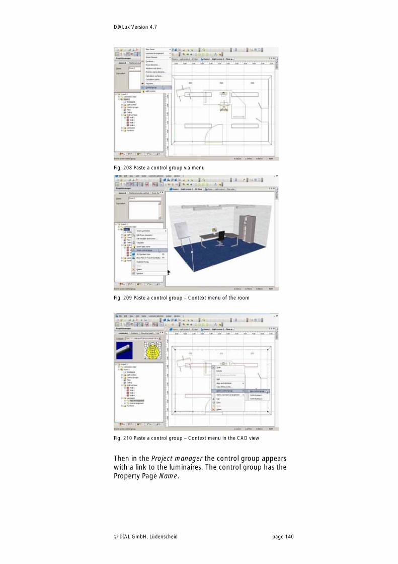
DIALux Version 4.7
DIAL GmbH, Lüdenscheid page 140
Fig. 208 Paste a control group via menu
Fig. 209 Paste a control group – Context menu of the room
Fig. 210 Paste a control group – Context menu in the CAD view
Then in the Project manager the control group appears with a link to the luminaires. The control group has the Property Page Name.
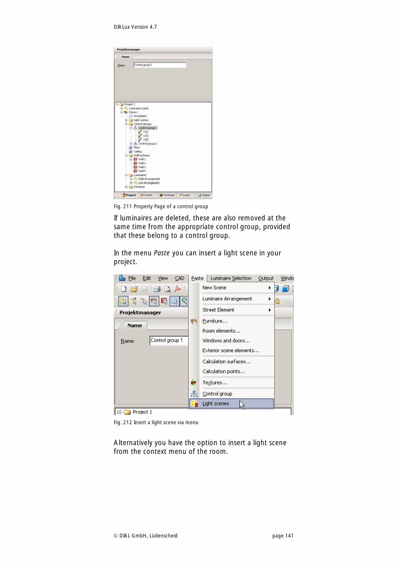
DIALux Version 4.7
DIAL GmbH, Lüdenscheid page 141
Fig. 211 Property Page of a control group
If luminaires are deleted, these are also removed at the same time from the appropriate control group, provided that these belong to a control group. In the menu Paste you can insert a light scene in your project.
Fig. 212 Insert a light scene via menu
Alternatively you have the option to insert a light scene from the context menu of the room.
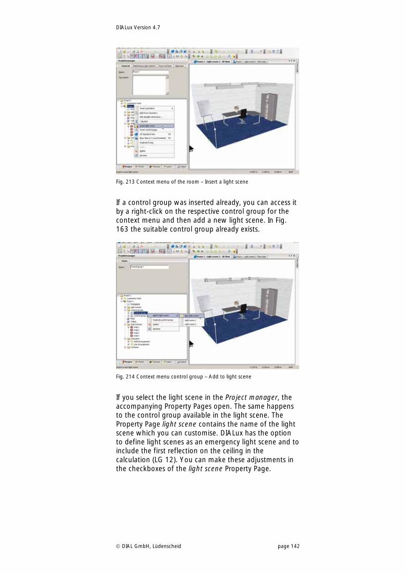
DIALux Version 4.7
DIAL GmbH, Lüdenscheid page 142
Fig. 213 Context menu of the room – Insert a light scene
If a control group was inserted already, you can access it by a right-click on the respective control group for the context menu and then add a new light scene. In Fig. 163 the suitable control group already exists.
Fig. 214 Context menu control group – Add to light scene
If you select the light scene in the Project manager, the accompanying Property Pages open. The same happens to the control group available in the light scene. The Property Page light scene contains the name of the light scene which you can customise. DIALux has the option to define light scenes as an emergency light scene and to include the first reflection on the ceiling in the calculation (LG 12). You can make these adjustments in the checkboxes of the light scene Property Page.
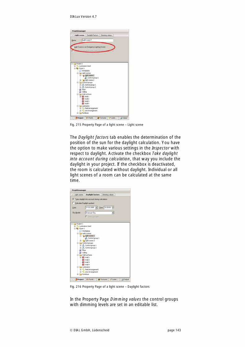
DIALux Version 4.7
DIAL GmbH, Lüdenscheid page 143
Fig. 215 Property Page of a light scene – Light scene
The Daylight factors tab enables the determination of the position of the sun for the daylight calculation. You have the option to make various settings in the Inspector with respect to daylight. Activate the checkbox Take daylight into account during calculation, that way you include the daylight in your project. If the checkbox is deactivated, the room is calculated without daylight. Individual or all light scenes of a room can be calculated at the same time.
Fig. 216 Property Page of a light scene – Daylight factors
In the Property Page Dimming values the control groups with dimming levels are set in an editable list.
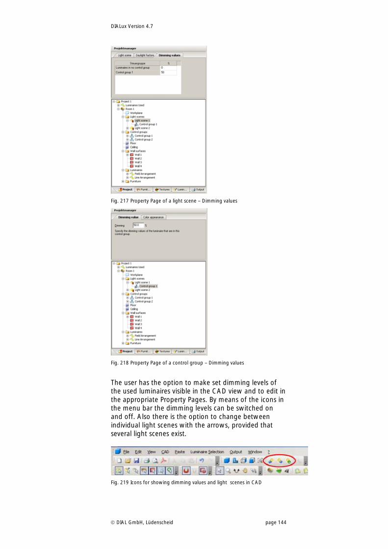
DIALux Version 4.7
DIAL GmbH, Lüdenscheid page 144
Fig. 217 Property Page of a light scene – Dimming values
Fig. 218 Property Page of a control group – Dimming values
The user has the option to make set dimming levels of the used luminaires visible in the CAD view and to edit in the appropriate Property Pages. By means of the icons in the menu bar the dimming levels can be switched on and off. Also there is the option to change between individual light scenes with the arrows, provided that several light scenes exist.
Fig. 219 Icons for showing dimming values and light scenes in CAD
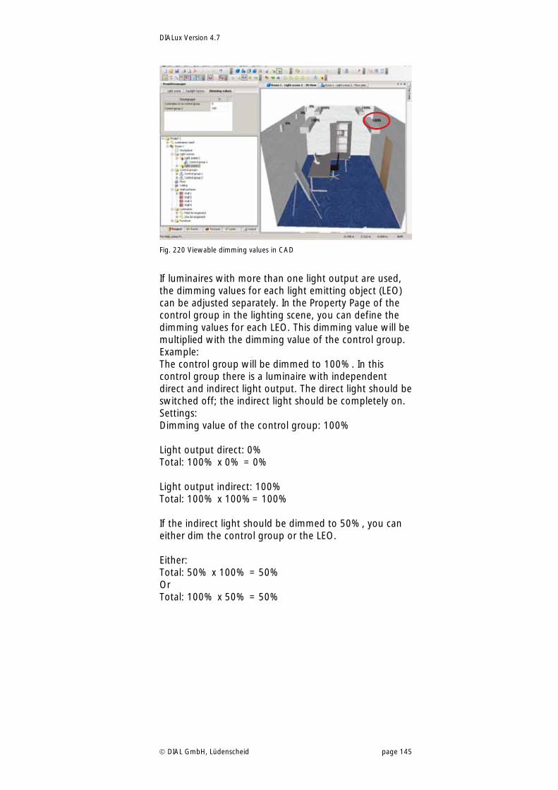
DIALux Version 4.7
DIAL GmbH, Lüdenscheid page 145
Fig. 220 Viewable dimming values in CAD
If luminaires with more than one light output are used, the dimming values for each light emitting object (LEO) can be adjusted separately. In the Property Page of the control group in the lighting scene, you can define the dimming values for each LEO. This dimming value will be multiplied with the dimming value of the control group. Example: The control group will be dimmed to 100%. In this control group there is a luminaire with independent direct and indirect light output. The direct light should be switched off; the indirect light should be completely on. Settings: Dimming value of the control group: 100% Light output direct: 0% Total: 100% x 0% = 0% Light output indirect: 100% Total: 100% x 100%= 100% If the indirect light should be dimmed to 50%, you can either dim the control group or the LEO. Either: Total: 50% x 100% = 50% Or Total: 100% x 50% = 50%
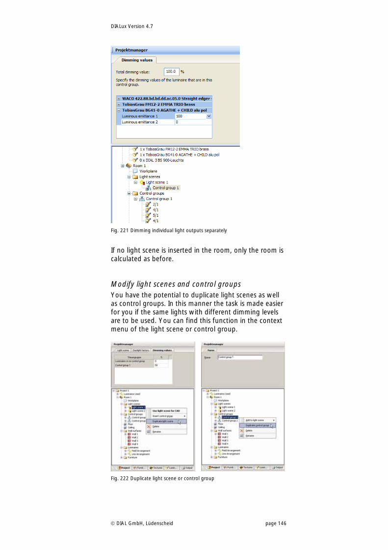
DIALux Version 4.7
DIAL GmbH, Lüdenscheid page 146
Fig. 221 Dimming individual light outputs separately
If no light scene is inserted in the room, only the room is calculated as before.
Modify light scenes and control groups You have the potential to duplicate light scenes as well as control groups. In this manner the task is made easier for you if the same lights with different dimming levels are to be used. You can find this function in the context menu of the light scene or control group.
Fig. 222 Duplicate light scene or control group
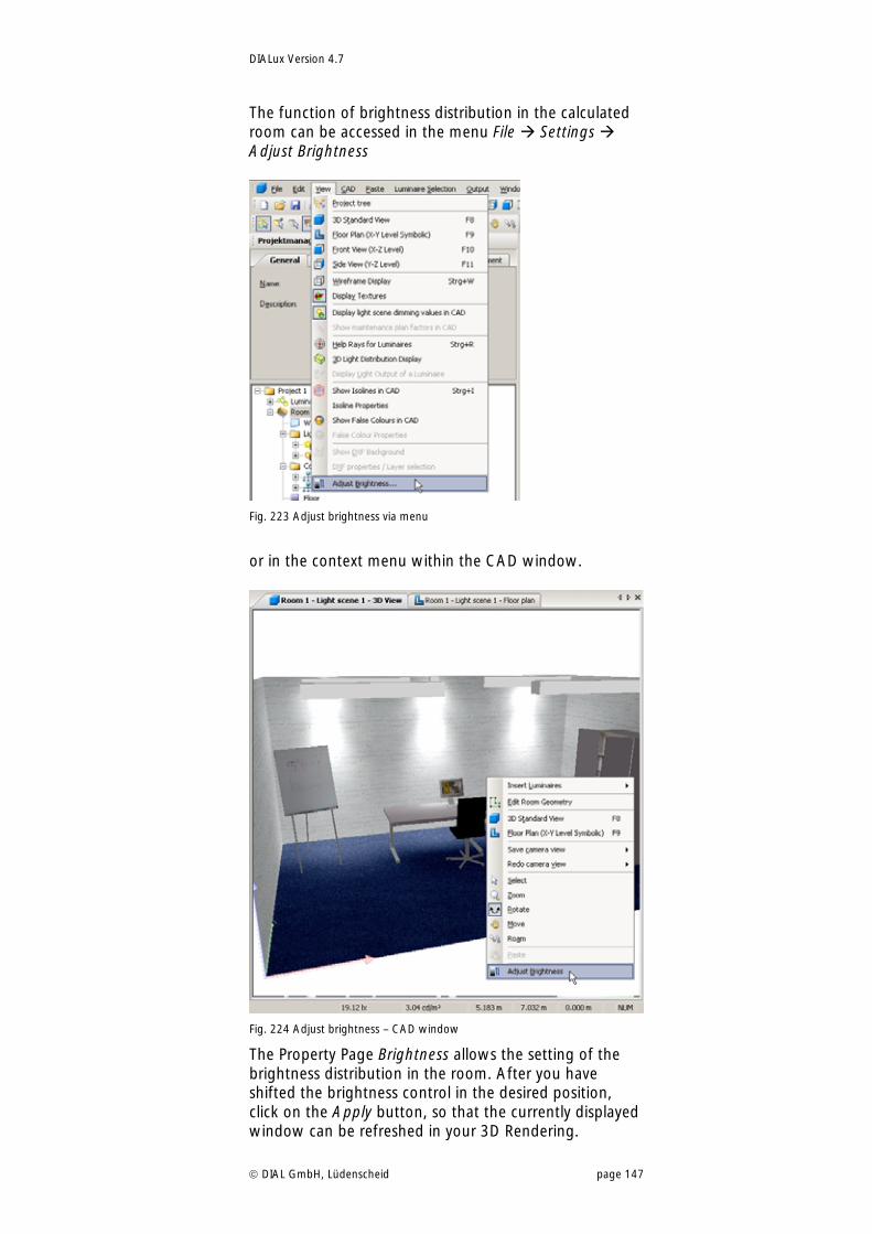
DIALux Version 4.7
DIAL GmbH, Lüdenscheid page 147
The function of brightness distribution in the calculated room can be accessed in the menu File Settings Adjust Brightness
Fig. 223 Adjust brightness via menu
or in the context menu within the CAD window.
Fig. 224 Adjust brightness – CAD window
The Property Page Brightness allows the setting of the brightness distribution in the room. After you have shifted the brightness control in the desired position, click on the Apply button, so that the currently displayed window can be refreshed in your 3D Rendering.
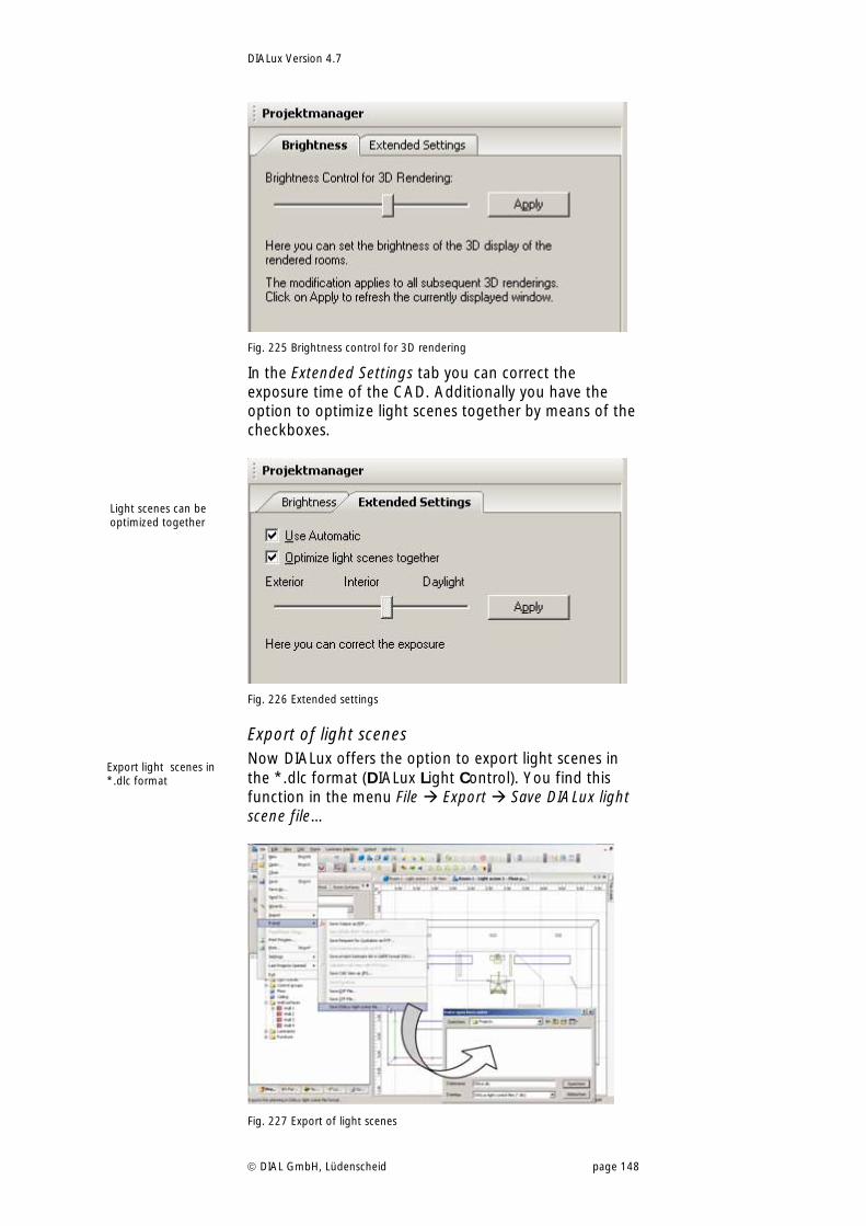
DIALux Version 4.7
DIAL GmbH, Lüdenscheid page 148
Fig. 225 Brightness control for 3D rendering
In the Extended Settings tab you can correct the exposure time of the CAD. Additionally you have the option to optimize light scenes together by means of the checkboxes.
Fig. 226 Extended settings
Export of light scenes Now DIALux offers the option to export light scenes in the *.dlc format (DIALux Light Control). You find this function in the menu File Export Save DIALux light scene file…
Fig. 227 Export of light scenes
Light scenes can be optimized together
Export light scenes in *.dlc format
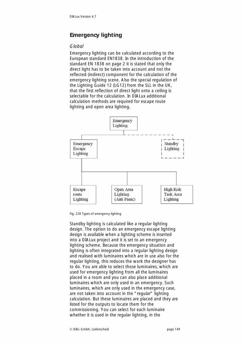
DIALux Version 4.7
DIAL GmbH, Lüdenscheid page 149
Emergency lighting
Global Emergency lighting can be calculated according to the European standard EN1838. In the introduction of the standard EN 1838 on page 2 it is stated that only the direct light has to be taken into account and not the reflected (indirect) component for the calculation of the emergency lighting scene. Also the special regulation of the Lighting Guide 12 (LG12) from the SLL in the UK, that the first reflection of direct light onto a ceiling is selectable for the calculation. In DIALux additional calculation methods are required for escape route lighting and open area lighting.
Fig. 228 Types of emergency lighting
Standby lighting is calculated like a regular lighting design. The option to do an emergency escape lighting design is available when a lighting scheme is inserted into a DIALux project and it is set to an emergency lighting scheme. Because the emergency situation and lighting is often integrated into a regular lighting design and realised with luminaires which are in use also for the regular lighting, this reduces the work the designer has to do. You are able to select those luminaires, which are used for emergency lighting from all the luminaires placed in a room and you can also place additional luminaires which are only used in an emergency. Such luminaires, which are only used in the emergency case, are not taken into account in the “regular” lighting calculation. But these luminaires are placed and they are listed for the outputs to locate them for the commissioning. You can select for each luminaire whether it is used in the regular lighting, in the
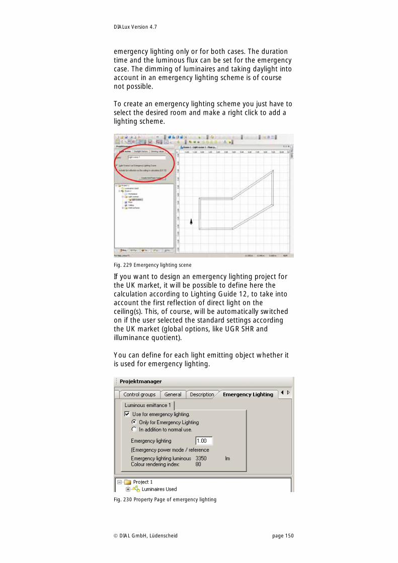
DIALux Version 4.7
DIAL GmbH, Lüdenscheid page 150
emergency lighting only or for both cases. The duration time and the luminous flux can be set for the emergency case. The dimming of luminaires and taking daylight into account in an emergency lighting scheme is of course not possible. To create an emergency lighting scheme you just have to select the desired room and make a right click to add a lighting scheme.
Fig. 229 Emergency lighting scene
If you want to design an emergency lighting project for the UK market, it will be possible to define here the calculation according to Lighting Guide 12, to take into account the first reflection of direct light on the ceiling(s). This, of course, will be automatically switched on if the user selected the standard settings according the UK market (global options, like UGR SHR and illuminance quotient). You can define for each light emitting object whether it is used for emergency lighting.
Fig. 230 Property Page of emergency lighting
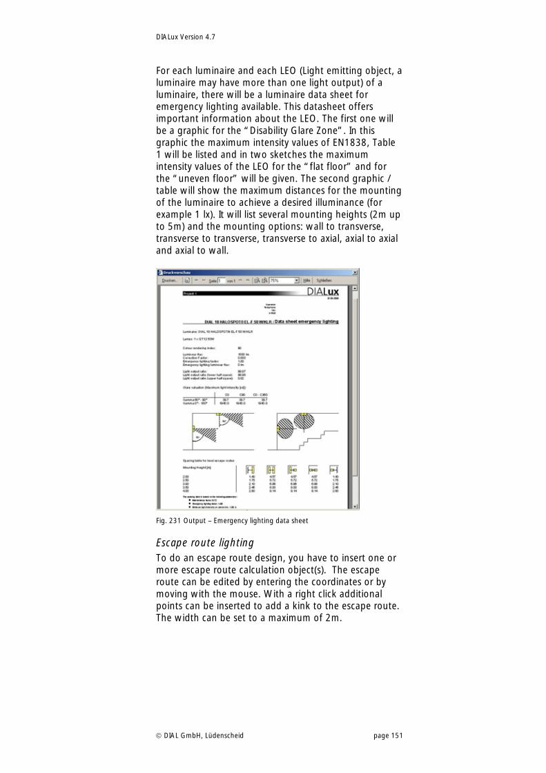
DIALux Version 4.7
DIAL GmbH, Lüdenscheid page 151
For each luminaire and each LEO (Light emitting object, a luminaire may have more than one light output) of a luminaire, there will be a luminaire data sheet for emergency lighting available. This datasheet offers important information about the LEO. The first one will be a graphic for the “Disability Glare Zone”. In this graphic the maximum intensity values of EN1838, Table 1 will be listed and in two sketches the maximum intensity values of the LEO for the “flat floor” and for the “uneven floor” will be given. The second graphic / table will show the maximum distances for the mounting of the luminaire to achieve a desired illuminance (for example 1 lx). It will list several mounting heights (2m up to 5m) and the mounting options: wall to transverse, transverse to transverse, transverse to axial, axial to axial and axial to wall.
Fig. 231 Output – Emergency lighting data sheet
Escape route lighting To do an escape route design, you have to insert one or more escape route calculation object(s). The escape route can be edited by entering the coordinates or by moving with the mouse. With a right click additional points can be inserted to add a kink to the escape route. The width can be set to a maximum of 2m.
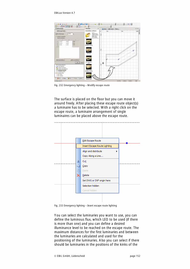
DIALux Version 4.7
DIAL GmbH, Lüdenscheid page 152
Fig. 232 Emergency lighting – Modify escape route
The surface is placed on the floor but you can move it around freely. After placing these escape route object(s) a luminaire has to be selected. With a right click on the escape route, a luminaire arrangement of single luminaires can be placed above the escape route.
Fig. 233 Emergency lighting – Insert escape route lighting
You can select the luminaries you want to use, you can define the luminous flux, which LEO to be used (if there is more than one) and you can define a desired illuminance level to be reached on the escape route. The maximum distances for the first luminaries and between the luminaries are calculated and used for the positioning of the luminaries. Also you can select if there should be luminaries in the positions of the kinks of the
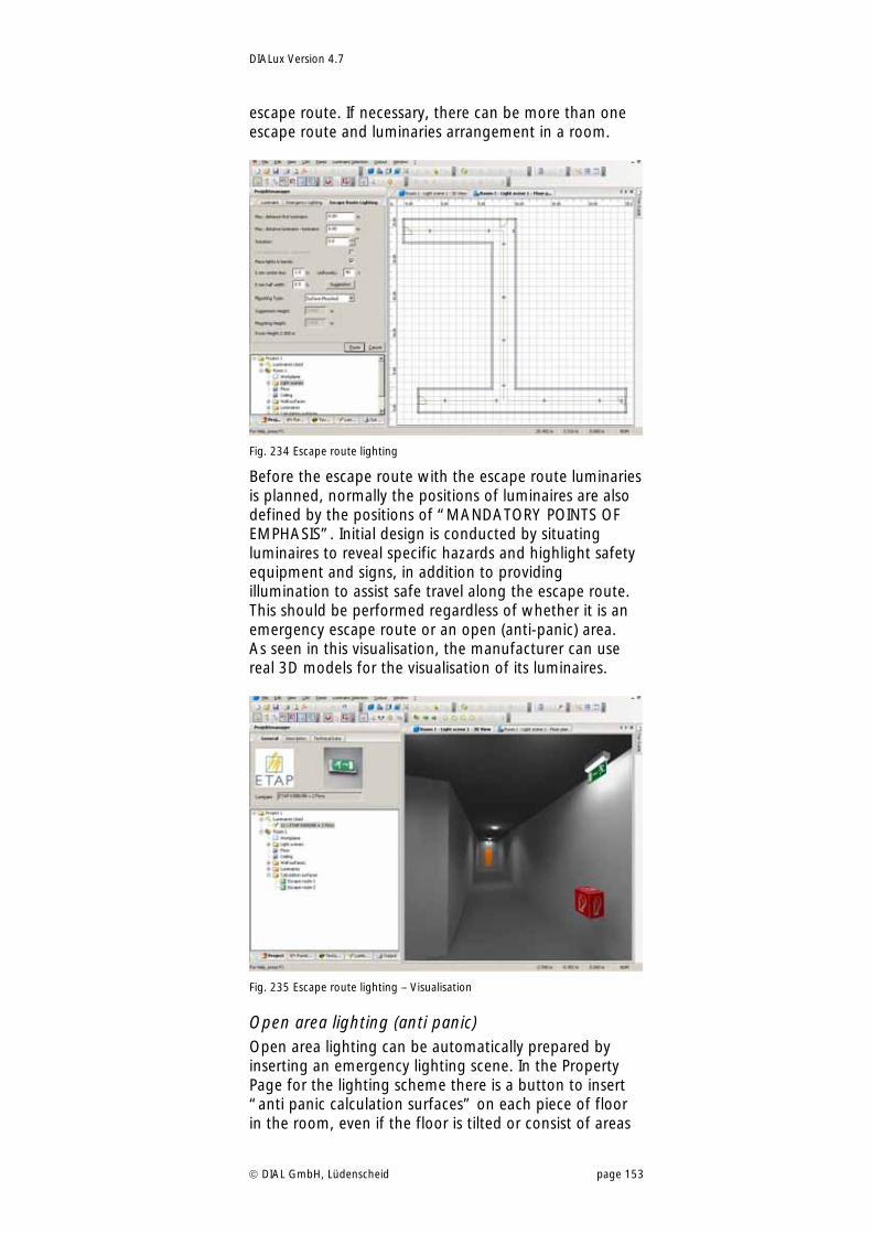
DIALux Version 4.7
DIAL GmbH, Lüdenscheid page 153
escape route. If necessary, there can be more than one escape route and luminaries arrangement in a room.
Fig. 234 Escape route lighting
Before the escape route with the escape route luminaries is planned, normally the positions of luminaires are also defined by the positions of “MANDATORY POINTS OF EMPHASIS”. Initial design is conducted by situating luminaires to reveal specific hazards and highlight safety equipment and signs, in addition to providing illumination to assist safe travel along the escape route. This should be performed regardless of whether it is an emergency escape route or an open (anti-panic) area. As seen in this visualisation, the manufacturer can use real 3D models for the visualisation of its luminaires.
Fig. 235 Escape route lighting – Visualisation
Open area lighting (anti panic) Open area lighting can be automatically prepared by inserting an emergency lighting scene. In the Property Page for the lighting scheme there is a button to insert “anti panic calculation surfaces” on each piece of floor in the room, even if the floor is tilted or consist of areas
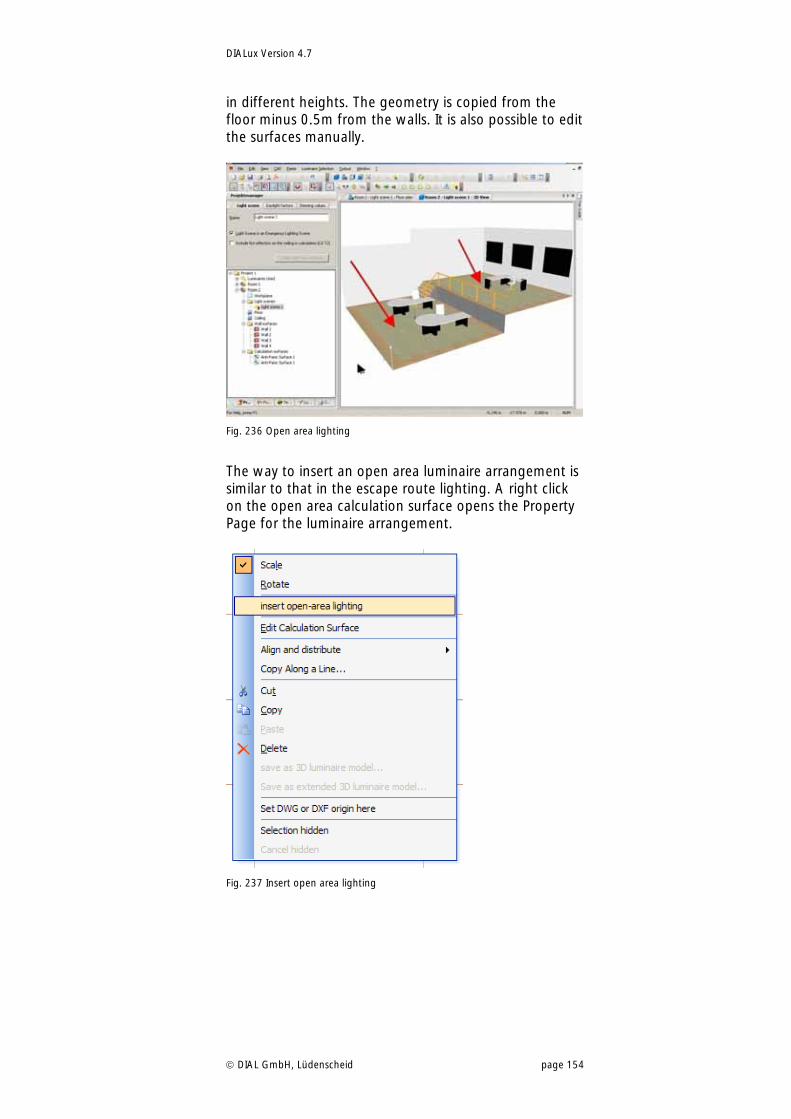
DIALux Version 4.7
DIAL GmbH, Lüdenscheid page 154
in different heights. The geometry is copied from the floor minus 0.5m from the walls. It is also possible to edit the surfaces manually.
Fig. 236 Open area lighting
The way to insert an open area luminaire arrangement is similar to that in the escape route lighting. A right click on the open area calculation surface opens the Property Page for the luminaire arrangement.
Fig. 237 Insert open area lighting
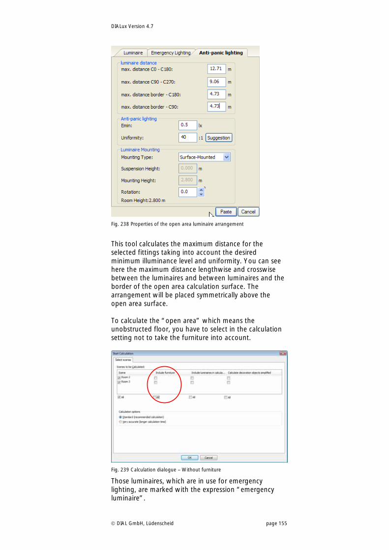
DIALux Version 4.7
DIAL GmbH, Lüdenscheid page 155
Fig. 238 Properties of the open area luminaire arrangement
This tool calculates the maximum distance for the selected fittings taking into account the desired minimum illuminance level and uniformity. You can see here the maximum distance lengthwise and crosswise between the luminaires and between luminaires and the border of the open area calculation surface. The arrangement will be placed symmetrically above the open area surface. To calculate the “open area” which means the unobstructed floor, you have to select in the calculation setting not to take the furniture into account.
Fig. 239 Calculation dialogue – Without furniture
Those luminaires, which are in use for emergency lighting, are marked with the expression “emergency luminaire”.
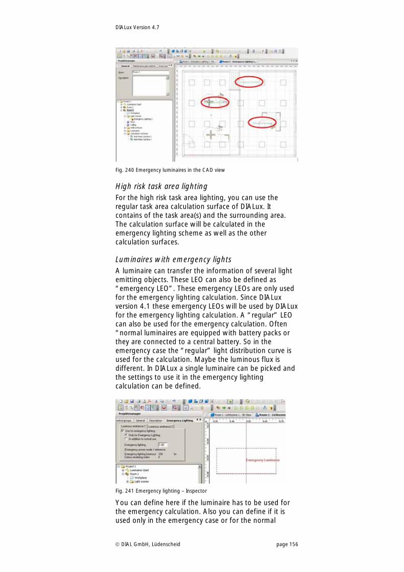
DIALux Version 4.7
DIAL GmbH, Lüdenscheid page 156
Fig. 240 Emergency luminaires in the CAD view
High risk task area lighting For the high risk task area lighting, you can use the regular task area calculation surface of DIALux. It contains of the task area(s) and the surrounding area. The calculation surface will be calculated in the emergency lighting scheme as well as the other calculation surfaces.
Luminaires with emergency lights A luminaire can transfer the information of several light emitting objects. These LEO can also be defined as “emergency LEO”. These emergency LEOs are only used for the emergency lighting calculation. Since DIALux version 4.1 these emergency LEOs will be used by DIALux for the emergency lighting calculation. A “regular” LEO can also be used for the emergency calculation. Often “normal luminaires are equipped with battery packs or they are connected to a central battery. So in the emergency case the “regular” light distribution curve is used for the calculation. Maybe the luminous flux is different. In DIALux a single luminaire can be picked and the settings to use it in the emergency lighting calculation can be defined.
Fig. 241 Emergency lighting – Inspector
You can define here if the luminaire has to be used for the emergency calculation. Also you can define if it is used only in the emergency case or for the normal
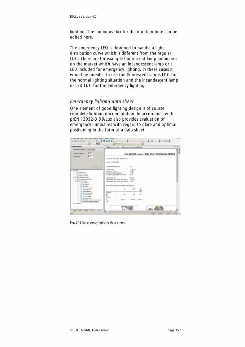
DIALux Version 4.7
DIAL GmbH, Lüdenscheid page 157
lighting. The luminous flux for the duration time can be edited here. The emergency LEO is designed to handle a light distribution curve which is different from the regular LDC. There are for example fluorescent lamp luminaires on the market which have an incandescent lamp or a LED included for emergency lighting. In these cases it would be possible to use the fluorescent lamps LDC for the normal lighting situation and the incandescent lamp or LED LDC for the emergency lighting.
Emergency lighting data sheet One element of good lighting design is of course complete lighting documentation. In accordance with prEN 13032-3 DIALux also provides evaluation of emergency luminaires with regard to glare and optimal positioning in the form of a data sheet.
Fig. 242 Emergency lighting data sheet
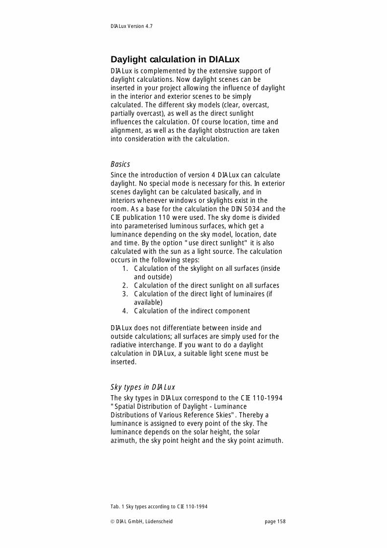
DIALux Version 4.7
DIAL GmbH, Lüdenscheid page 158
Daylight calculation in DIALux DIALux is complemented by the extensive support of daylight calculations. Now daylight scenes can be inserted in your project allowing the influence of daylight in the interior and exterior scenes to be simply calculated. The different sky models (clear, overcast, partially overcast), as well as the direct sunlight influences the calculation. Of course location, time and alignment, as well as the daylight obstruction are taken into consideration with the calculation.
Basics Since the introduction of version 4 DIALux can calculate daylight. No special mode is necessary for this. In exterior scenes daylight can be calculated basically, and in interiors whenever windows or skylights exist in the room. As a base for the calculation the DIN 5034 and the CIE publication 110 were used. The sky dome is divided into parameterised luminous surfaces, which get a luminance depending on the sky model, location, date and time. By the option "use direct sunlight" it is also calculated with the sun as a light source. The calculation occurs in the following steps:
1. Calculation of the skylight on all surfaces (inside and outside)
2. Calculation of the direct sunlight on all surfaces 3. Calculation of the direct light of luminaires (if
available) 4. Calculation of the indirect component
DIALux does not differentiate between inside and outside calculations; all surfaces are simply used for the radiative interchange. If you want to do a daylight calculation in DIALux, a suitable light scene must be inserted.
Sky types in DIALux The sky types in DIALux correspond to the CIE 110-1994 "Spatial Distribution of Daylight - Luminance Distributions of Various Reference Skies". Thereby a luminance is assigned to every point of the sky. The luminance depends on the solar height, the solar azimuth, the sky point height and the sky point azimuth.
Tab. 1 Sky types according to CIE 110-1994
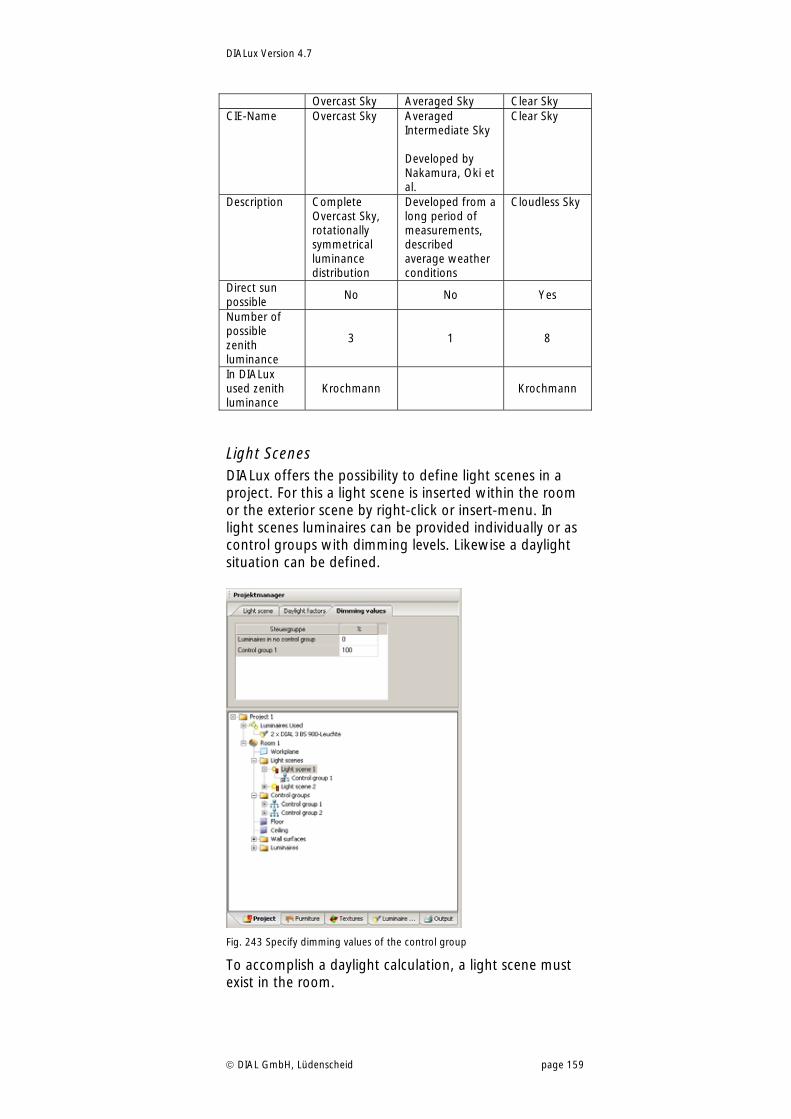
DIALux Version 4.7
DIAL GmbH, Lüdenscheid page 159
Overcast Sky Averaged Sky Clear Sky CIE-Name Overcast Sky Averaged
Intermediate Sky Developed by Nakamura, Oki et al.
Clear Sky
Description Complete Overcast Sky, rotationally symmetrical luminance distribution
Developed from a long period of measurements, described average weather conditions
Cloudless Sky
Direct sun possible
No No Yes
Number of possible zenith luminance
3 1 8
In DIALux used zenith luminance
Krochmann Krochmann
Light Scenes DIALux offers the possibility to define light scenes in a project. For this a light scene is inserted within the room or the exterior scene by right-click or insert-menu. In light scenes luminaires can be provided individually or as control groups with dimming levels. Likewise a daylight situation can be defined.
Fig. 243 Specify dimming values of the control group
To accomplish a daylight calculation, a light scene must exist in the room.
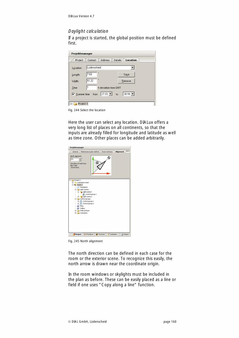
DIALux Version 4.7
DIAL GmbH, Lüdenscheid page 160
Daylight calculation If a project is started, the global position must be defined first.
Fig. 244 Select the location
Here the user can select any location. DIALux offers a very long list of places on all continents, so that the inputs are already filled for longitude and latitude as well as time zone. Other places can be added arbitrarily.
Fig. 245 North alignment
The north direction can be defined in each case for the room or the exterior scene. To recognize this easily, the north arrow is drawn near the coordinate origin. In the room windows or skylights must be included in the plan as before. These can be easily placed as a line or field if one uses "Copy along a line" function.
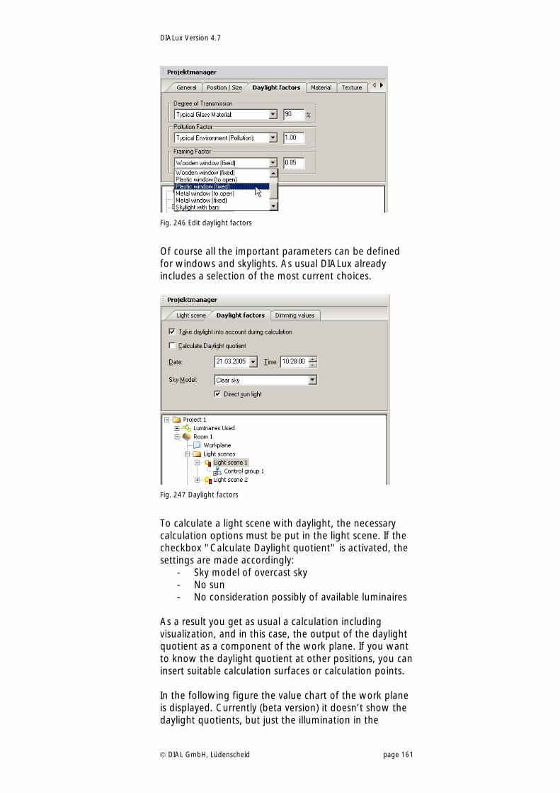
DIALux Version 4.7
DIAL GmbH, Lüdenscheid page 161
Fig. 246 Edit daylight factors
Of course all the important parameters can be defined for windows and skylights. As usual DIALux already includes a selection of the most current choices.
Fig. 247 Daylight factors
To calculate a light scene with daylight, the necessary calculation options must be put in the light scene. If the checkbox "Calculate Daylight quotient" is activated, the settings are made accordingly:
- Sky model of overcast sky - No sun - No consideration possibly of available luminaires
As a result you get as usual a calculation including visualization, and in this case, the output of the daylight quotient as a component of the work plane. If you want to know the daylight quotient at other positions, you can insert suitable calculation surfaces or calculation points. In the following figure the value chart of the work plane is displayed. Currently (beta version) it doesn’t show the daylight quotients, but just the illumination in the
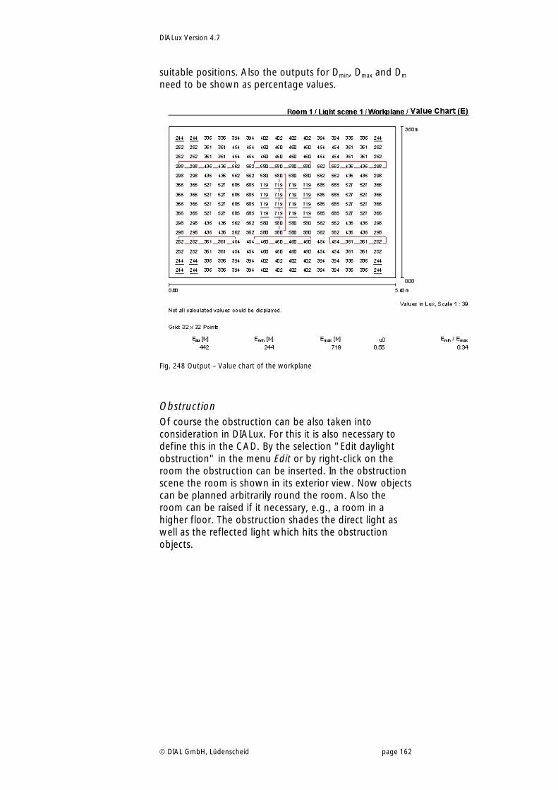
DIALux Version 4.7
DIAL GmbH, Lüdenscheid page 162
suitable positions. Also the outputs for Dmin, Dmax and Dm need to be shown as percentage values.
Fig. 248 Output – Value chart of the workplane
Obstruction Of course the obstruction can be also taken into consideration in DIALux. For this it is also necessary to define this in the CAD. By the selection "Edit daylight obstruction" in the menu Edit or by right-click on the room the obstruction can be inserted. In the obstruction scene the room is shown in its exterior view. Now objects can be planned arbitrarily round the room. Also the room can be raised if it necessary, e.g., a room in a higher floor. The obstruction shades the direct light as well as the reflected light which hits the obstruction objects.
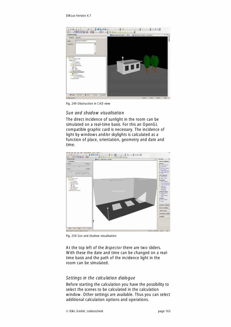
DIALux Version 4.7
DIAL GmbH, Lüdenscheid page 163
Fig. 249 Obstruction in CAD view
Sun and shadow visualisation The direct incidence of sunlight in the room can be simulated on a real-time basis. For this an OpenGL compatible graphic card is necessary. The incidence of light by windows and/or skylights is calculated as a function of place, orientation, geometry and date and time.
Fig. 250 Sun and shadow visualisation
At the top left of the Inspector there are two sliders. With these the date and time can be changed on a real-time basis and the path of the incidence light in the room can be simulated.
Settings in the calculation dialogue Before starting the calculation you have the possibility to select the scenes to be calculated in the calculation window. Other settings are available. Thus you can select additional calculation options and operations.
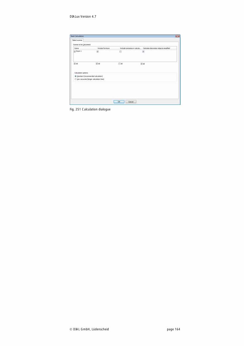
DIALux Version 4.7
DIAL GmbH, Lüdenscheid page 164
Fig. 251 Calculation dialogue
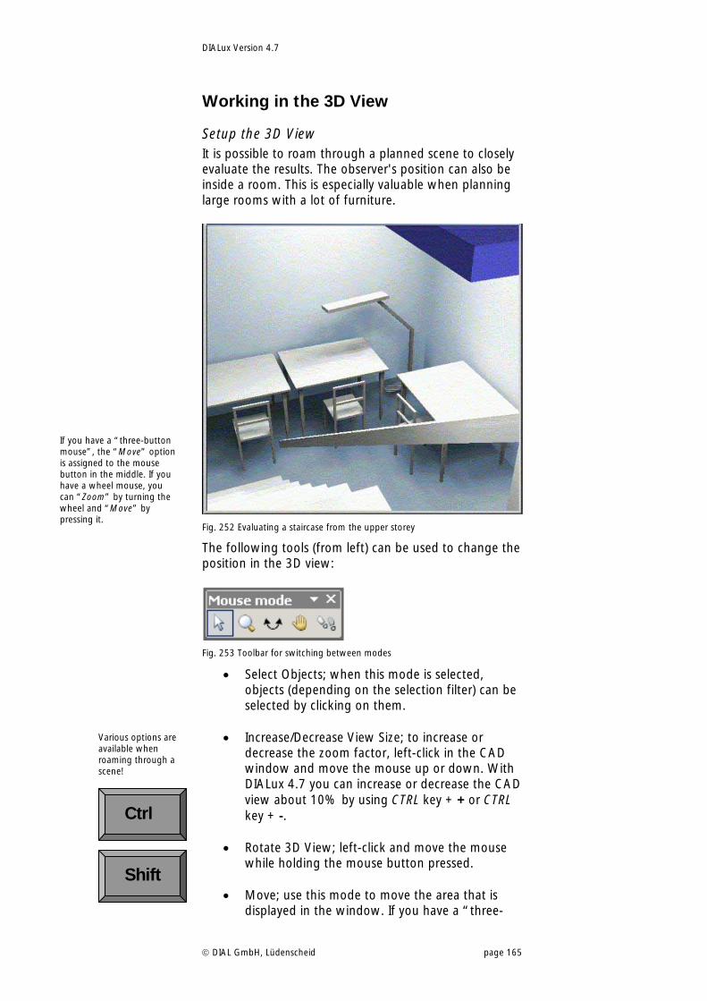
DIALux Version 4.7
DIAL GmbH, Lüdenscheid page 165
Working in the 3D View
Setup the 3D View It is possible to roam through a planned scene to closely evaluate the results. The observer's position can also be inside a room. This is especially valuable when planning large rooms with a lot of furniture.
Fig. 252 Evaluating a staircase from the upper storey
The following tools (from left) can be used to change the position in the 3D view:
Fig. 253 Toolbar for switching between modes
Select Objects; when this mode is selected, objects (depending on the selection filter) can be selected by clicking on them.
Increase/Decrease View Size; to increase or decrease the zoom factor, left-click in the CAD window and move the mouse up or down. With DIALux 4.7 you can increase or decrease the CAD view about 10% by using CTRL key + + or CTRL key + -.
Rotate 3D View; left-click and move the mouse while holding the mouse button pressed.
Move; use this mode to move the area that is displayed in the window. If you have a “three-
If you have a “three-button mouse”, the “Move” option is assigned to the mouse button in the middle. If you have a wheel mouse, you can “Zoom” by turning the wheel and “Move” by pressing it.
Various options are available when roaming through a scene!
Shift
Ctrl
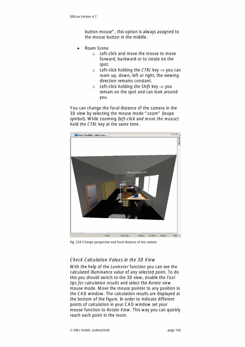
DIALux Version 4.7
DIAL GmbH, Lüdenscheid page 166
button mouse”, this option is always assigned to the mouse button in the middle.
Roam Scene o Left-click and move the mouse to move
forward, backward or to rotate on the spot.
o Left-click holding the CTRL key you can roam up, down, left or right, the viewing direction remains constant.
o Left-click holding the Shift key you remain on the spot and can look around you.
You can change the focal distance of the camera in the 3D view by selecting the mouse mode “zoom” (loupe symbol). While zooming (left-click and move the mouse) hold the CTRL key at the same time.
Fig. 254 Change perspective and focal distance of the camera
Check Calculation Values in the 3D View With the help of the Luxmeter function you can see the calculated illuminance value of any selected point. To do this you should switch to the 3D view, enable the Tool tips for calculation results and select the Rotate view mouse mode. Move the mouse pointer to any position in the CAD window. The calculation results are displayed at the bottom of the figure. In order to indicate different points of calculation in your CAD window set your mouse function to Rotate View. This way you can quickly reach each point in the room.
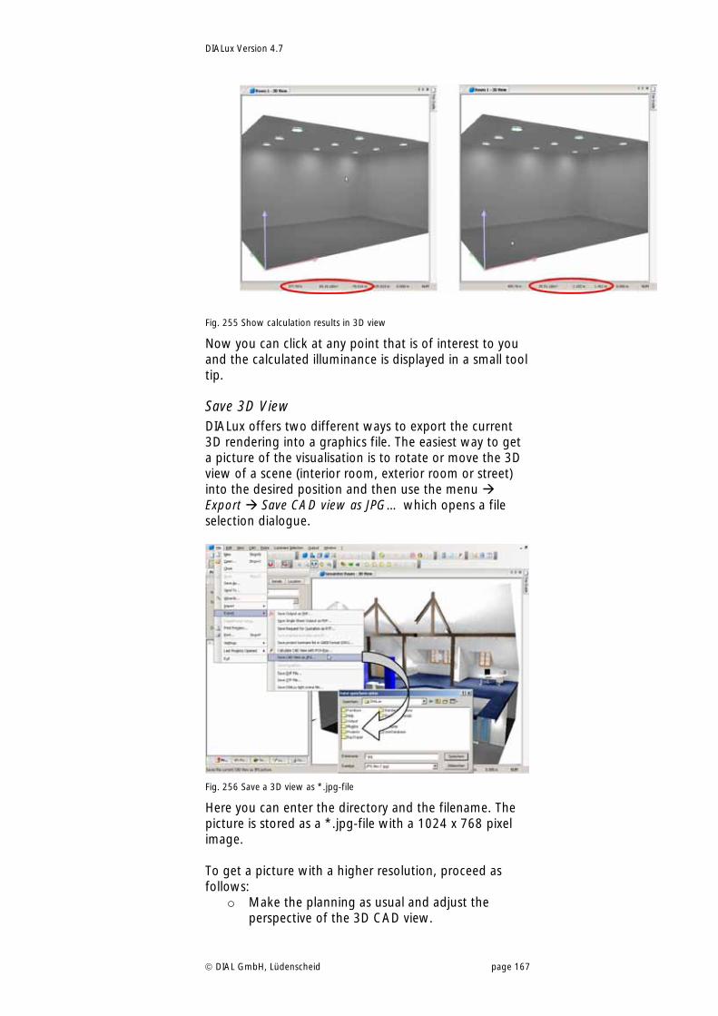
DIALux Version 4.7
DIAL GmbH, Lüdenscheid page 167
Fig. 255 Show calculation results in 3D view
Now you can click at any point that is of interest to you and the calculated illuminance is displayed in a small tool tip.
Save 3D View DIALux offers two different ways to export the current 3D rendering into a graphics file. The easiest way to get a picture of the visualisation is to rotate or move the 3D view of a scene (interior room, exterior room or street) into the desired position and then use the menu Export Save CAD view as JPG… which opens a file selection dialogue.
Fig. 256 Save a 3D view as *.jpg-file
Here you can enter the directory and the filename. The picture is stored as a *.jpg-file with a 1024 x 768 pixel image. To get a picture with a higher resolution, proceed as follows:
o Make the planning as usual and adjust the perspective of the 3D CAD view.
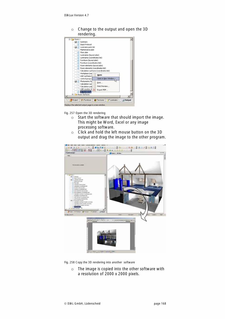
DIALux Version 4.7
DIAL GmbH, Lüdenscheid page 168
o Change to the output and open the 3D rendering.
Fig. 257 Open the 3D rendering
o Start the software that should import the image. This might be Word, Excel or any image processing software.
o Click and hold the left mouse button on the 3D output and drag the image to the other program.
Fig. 258 Copy the 3D rendering into another software
o The image is copied into the other software with a resolution of 2000 x 2000 pixels.
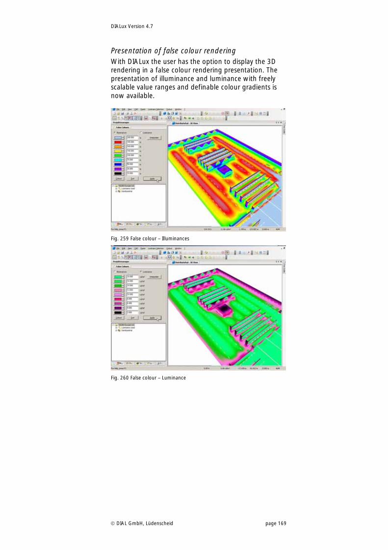
DIALux Version 4.7
DIAL GmbH, Lüdenscheid page 169
Presentation of false colour rendering With DIALux the user has the option to display the 3D rendering in a false colour rendering presentation. The presentation of illuminance and luminance with freely scalable value ranges and definable colour gradients is now available.
Fig. 259 False colour – Illuminances
Fig. 260 False colour – Luminance
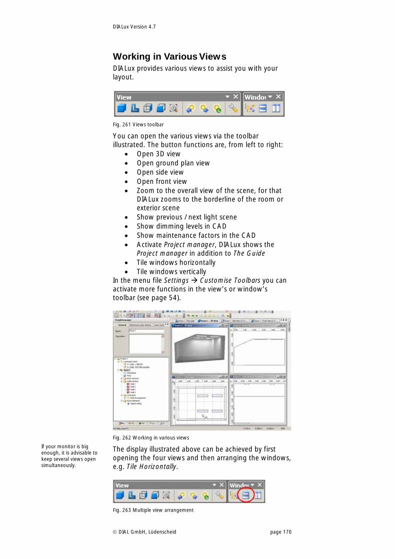
DIALux Version 4.7
DIAL GmbH, Lüdenscheid page 170
Working in Various Views DIALux provides various views to assist you with your layout.
Fig. 261 Views toolbar
You can open the various views via the toolbar illustrated. The button functions are, from left to right:
Open 3D view Open ground plan view Open side view Open front view Zoom to the overall view of the scene, for that
DIALux zooms to the borderline of the room or exterior scene
Show previous / next light scene Show dimming levels in CAD Show maintenance factors in the CAD Activate Project manager, DIALux shows the
Project manager in addition to The Guide Tile windows horizontally Tile windows vertically
In the menu file Settings Customise Toolbars you can activate more functions in the view’s or window’s toolbar (see page 54).
Fig. 262 Working in various views
The display illustrated above can be achieved by first opening the four views and then arranging the windows, e.g. Tile Horizontally.
Fig. 263 Multiple view arrangement
If your monitor is big enough, it is advisable to keep several views open simultaneously.
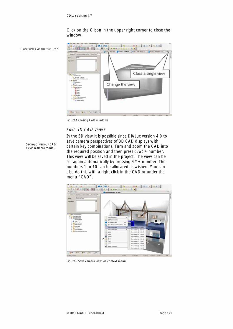
DIALux Version 4.7
DIAL GmbH, Lüdenscheid page 171
Click on the X icon in the upper right corner to close the window.
Fig. 264 Closing CAD windows
Save 3D CAD views In the 3D view it is possible since DIALux version 4.0 to save camera perspectives of 3D CAD displays with certain key combinations. Turn and zoom the CAD into the required position and then press CTRL + number. This view will be saved in the project. The view can be set again automatically by pressing Alt + number. The numbers 1 to 10 can be allocated as wished. You can also do this with a right click in the CAD or under the menu “CAD”.
Fig. 265 Save camera view via context menu
Close views via the “X” icon
Saving of various CAD views (camera mode).
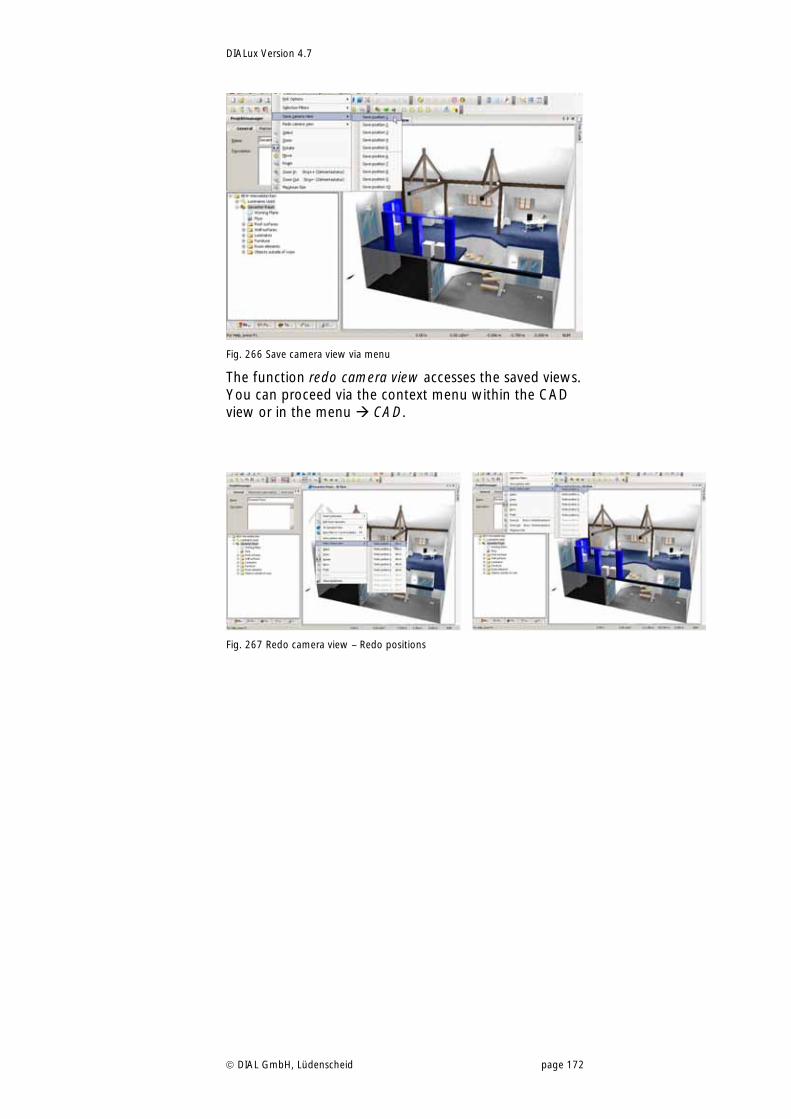
DIALux Version 4.7
DIAL GmbH, Lüdenscheid page 172
Fig. 266 Save camera view via menu
The function redo camera view accesses the saved views. You can proceed via the context menu within the CAD view or in the menu CAD.
Fig. 267 Redo camera view – Redo positions
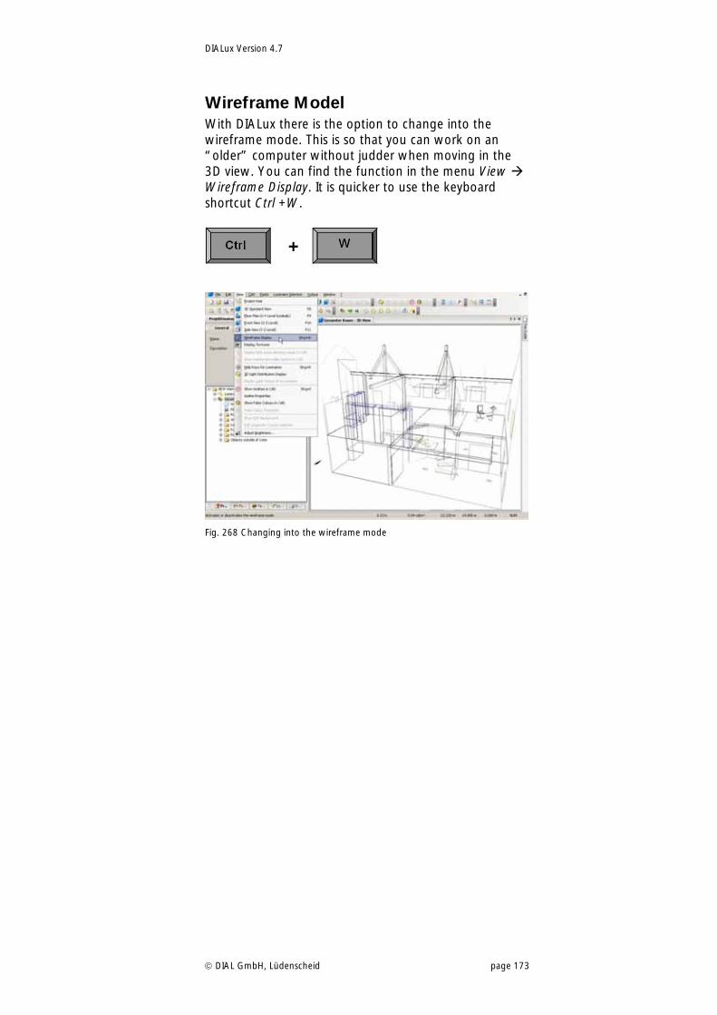
DIALux Version 4.7
DIAL GmbH, Lüdenscheid page 173
Wireframe Model With DIALux there is the option to change into the wireframe mode. This is so that you can work on an “older” computer without judder when moving in the 3D view. You can find the function in the menu View Wireframe Display. It is quicker to use the keyboard shortcut Ctrl +W.
Fig. 268 Changing into the wireframe mode
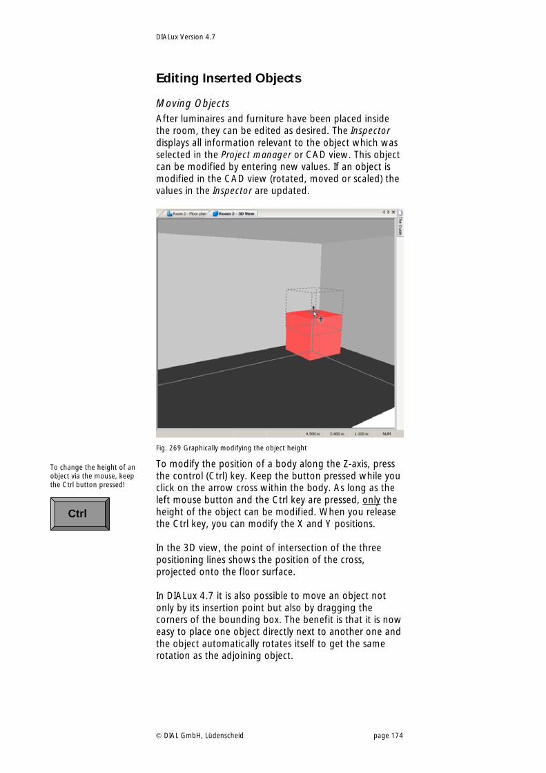
DIALux Version 4.7
DIAL GmbH, Lüdenscheid page 174
Editing Inserted Objects
Moving Objects After luminaires and furniture have been placed inside the room, they can be edited as desired. The Inspector displays all information relevant to the object which was selected in the Project manager or CAD view. This object can be modified by entering new values. If an object is modified in the CAD view (rotated, moved or scaled) the values in the Inspector are updated.
Fig. 269 Graphically modifying the object height
To modify the position of a body along the Z-axis, press the control (Ctrl) key. Keep the button pressed while you click on the arrow cross within the body. As long as the left mouse button and the Ctrl key are pressed, only the height of the object can be modified. When you release the Ctrl key, you can modify the X and Y positions. In the 3D view, the point of intersection of the three positioning lines shows the position of the cross, projected onto the floor surface. In DIALux 4.7 it is also possible to move an object not only by its insertion point but also by dragging the corners of the bounding box. The benefit is that it is now easy to place one object directly next to another one and the object automatically rotates itself to get the same rotation as the adjoining object.
To change the height of an object via the mouse, keep the Ctrl button pressed!
Ctrl
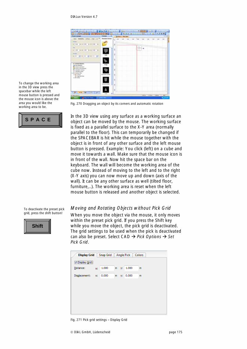
DIALux Version 4.7
DIAL GmbH, Lüdenscheid page 175
Fig. 270 Dragging an object by its corners and automatic rotation
In the 3D view using any surface as a working surface an object can be moved by the mouse. The working surface is fixed as a parallel surface to the X-Y area (normally parallel to the floor). This can temporarily be changed if the SPACEBAR is hit while the mouse together with the object is in front of any other surface and the left mouse button is pressed. Example: You click (left) on a cube and move it towards a wall. Make sure that the mouse icon is in front of the wall. Now hit the space bar on the keyboard. The wall will become the working area of the cube now. Instead of moving to the left and to the right (X-Y axis) you can now move up and down (axis of the wall). It can be any other surface as well (tilted floor, furniture,..). The working area is reset when the left mouse button is released and another object is selected.
Moving and Rotating Objects without Pick Grid When you move the object via the mouse, it only moves within the preset pick grid. If you press the Shift key while you move the object, the pick grid is deactivated. The grid settings to be used when the pick is deactivated can also be preset. Select CAD Pick Options Set Pick Grid.
Fig. 271 Pick grid settings – Display Grid
To deactivate the preset pick grid, press the shift button!
Shift
To change the working area in the 3D view press the spacebar while the left mouse button is pressed and the mouse icon is above the area you would like the working area to be.
S P A C E
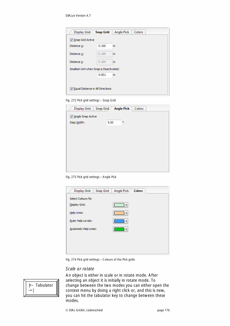
DIALux Version 4.7
DIAL GmbH, Lüdenscheid page 176
Fig. 272 Pick grid settings – Snap Grid
Fig. 273 Pick grid settings – Angle Pick
Fig. 274 Pick grid settings – Colours of the Pick grids
Scale or rotate An object is either in scale or in rotate mode. After selecting an object it is initially in rotate mode. To change between the two modes you can either open the context menu by doing a right click or, and this is new, you can hit the tabulator key to change between these modes.
|<- Tabulator ->|
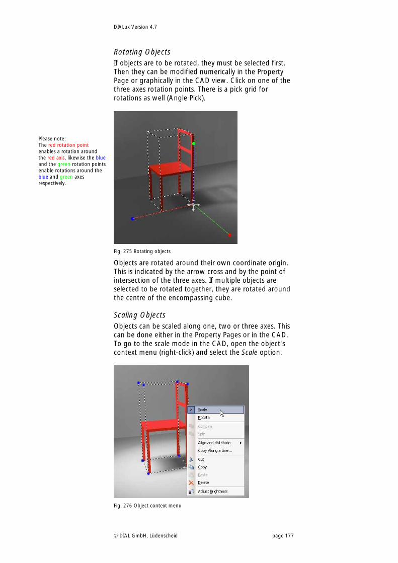
DIALux Version 4.7
DIAL GmbH, Lüdenscheid page 177
Rotating Objects If objects are to be rotated, they must be selected first. Then they can be modified numerically in the Property Page or graphically in the CAD view. Click on one of the three axes rotation points. There is a pick grid for rotations as well (Angle Pick).
Fig. 275 Rotating objects
Objects are rotated around their own coordinate origin. This is indicated by the arrow cross and by the point of intersection of the three axes. If multiple objects are selected to be rotated together, they are rotated around the centre of the encompassing cube.
Scaling Objects Objects can be scaled along one, two or three axes. This can be done either in the Property Pages or in the CAD. To go to the scale mode in the CAD, open the object's context menu (right-click) and select the Scale option.
Fig. 276 Object context menu
Please note: The red rotation point enables a rotation around the red axis, likewise the blue and the green rotation points enable rotations around the blue and green axes respectively.
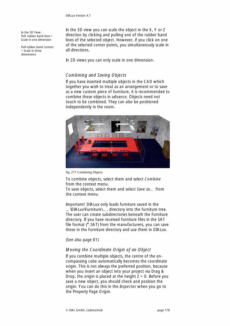
DIALux Version 4.7
DIAL GmbH, Lüdenscheid page 178
In the 3D view you can scale the object in the X, Y or Z direction by clicking and pulling one of the rubber band lines of the selected object. However, if you click on one of the selected corner points, you simultaneously scale in all directions. In 2D views you can only scale in one dimension.
Combining and Saving Objects If you have inserted multiple objects in the CAD which together you wish to treat as an arrangement or to save as a new custom piece of furniture, it is recommended to combine these objects in advance. Objects need not touch to be combined. They can also be positioned independently in the room.
Fig. 277 Combining Objects
To combine objects, select them and select Combine from the context menu. To save objects, select them and select Save as… from the context menu. Important! DIALux only loads furniture saved in the …\DIALux\Furniture\…. directory into the furniture tree. The user can create subdirectories beneath the Furniture directory. If you have received furniture files in the SAT file format (*.SAT) from the manufacturers, you can save these in the Furniture directory and use them in DIALux. (See also page 81)
Moving the Coordinate Origin of an Object If you combine multiple objects, the centre of the en-compassing cube automatically becomes the coordinate origin. This is not always the preferred position, because when you insert an object into your project via Drag & Drop, the origin is placed at the height Z = 0. Before you save a new object, you should check and position the origin. You can do this in the Inspector when you go to the Property Page Origin.
In the 3D View: Pull rubber band lines = Scale in one dimension Pull rubber band corners = Scale in three dimensions
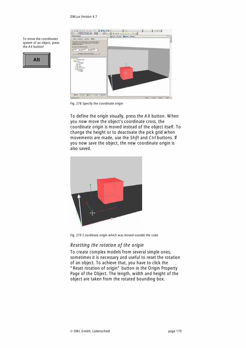
DIALux Version 4.7
DIAL GmbH, Lüdenscheid page 179
Fig. 278 Specify the coordinate origin
To define the origin visually, press the Alt button. When you now move the object's coordinate cross, the coordinate origin is moved instead of the object itself. To change the height or to deactivate the pick grid when movements are made, use the Shift and Ctrl buttons. If you now save the object, the new coordinate origin is also saved.
Fig. 279 Coordinate origin which was moved outside the cube
Resetting the rotation of the origin To create complex models from several simple ones, sometimes it is necessary and useful to reset the rotation of an object. To achieve that, you have to click the “Reset rotation of origin” button in the Origin Property Page of the Object. The length, width and height of the object are taken from the rotated bounding box.
To move the coordinates system of an object, press the Alt button!
Alt
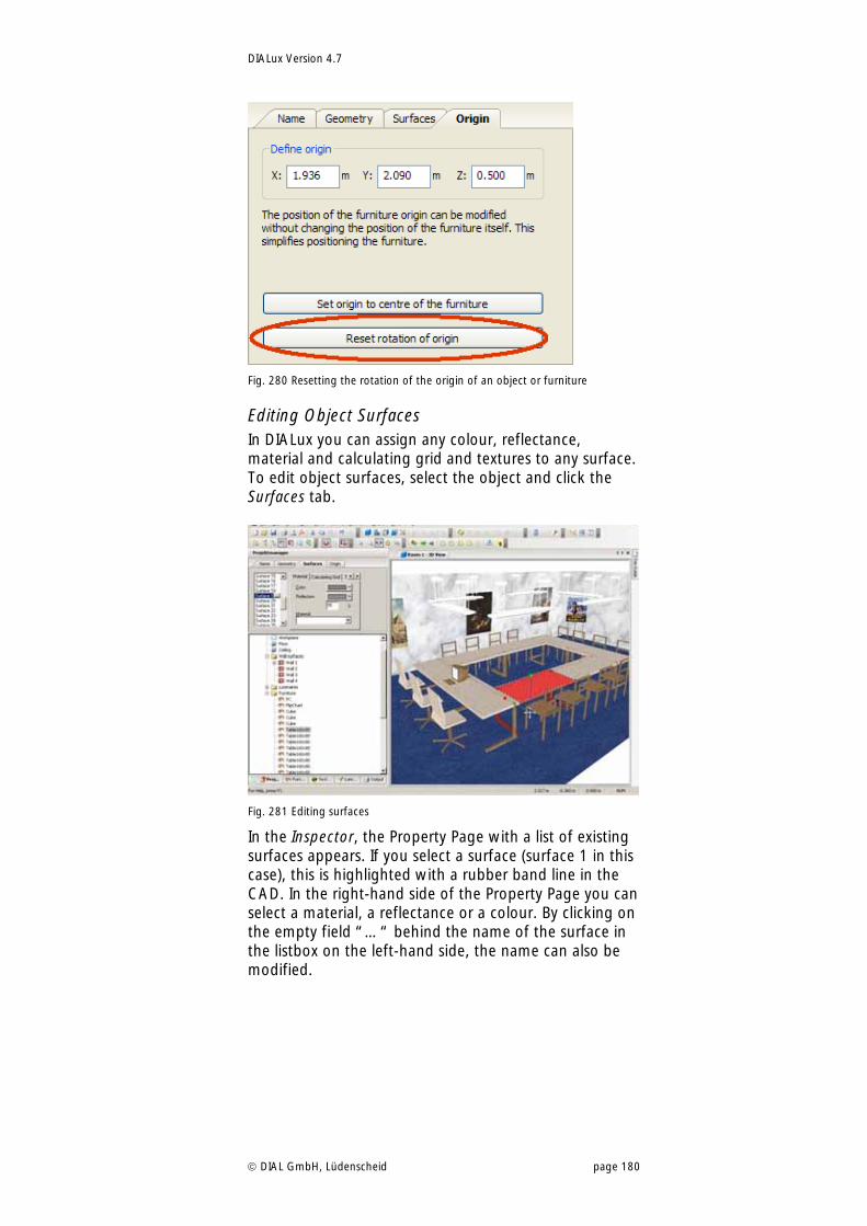
DIALux Version 4.7
DIAL GmbH, Lüdenscheid page 180
Fig. 280 Resetting the rotation of the origin of an object or furniture
Editing Object Surfaces In DIALux you can assign any colour, reflectance, material and calculating grid and textures to any surface. To edit object surfaces, select the object and click the Surfaces tab.
Fig. 281 Editing surfaces
In the Inspector, the Property Page with a list of existing surfaces appears. If you select a surface (surface 1 in this case), this is highlighted with a rubber band line in the CAD. In the right-hand side of the Property Page you can select a material, a reflectance or a colour. By clicking on the empty field “…“ behind the name of the surface in the listbox on the left-hand side, the name can also be modified.
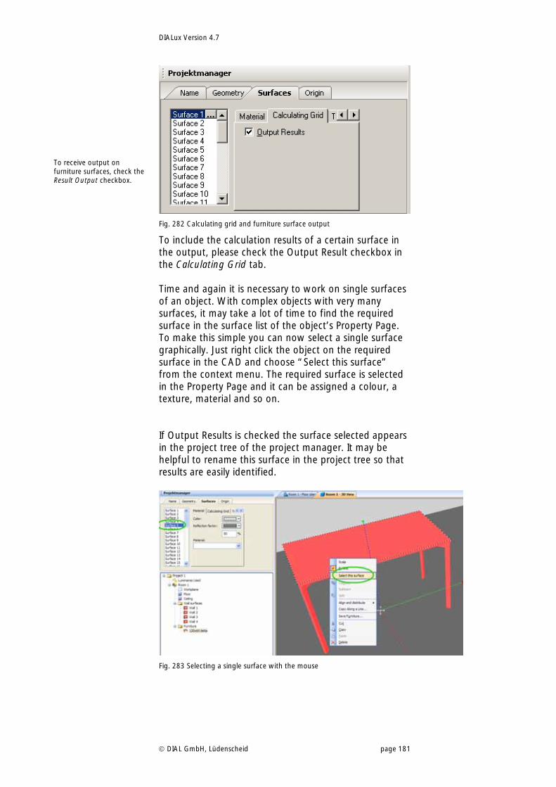
DIALux Version 4.7
DIAL GmbH, Lüdenscheid page 181
Fig. 282 Calculating grid and furniture surface output
To include the calculation results of a certain surface in the output, please check the Output Result checkbox in the Calculating Grid tab. Time and again it is necessary to work on single surfaces of an object. With complex objects with very many surfaces, it may take a lot of time to find the required surface in the surface list of the object’s Property Page. To make this simple you can now select a single surface graphically. Just right click the object on the required surface in the CAD and choose “Select this surface” from the context menu. The required surface is selected in the Property Page and it can be assigned a colour, a texture, material and so on. If Output Results is checked the surface selected appears in the project tree of the project manager. It may be helpful to rename this surface in the project tree so that results are easily identified.
Fig. 283 Selecting a single surface with the mouse
To receive output on furniture surfaces, check the Result Output checkbox.
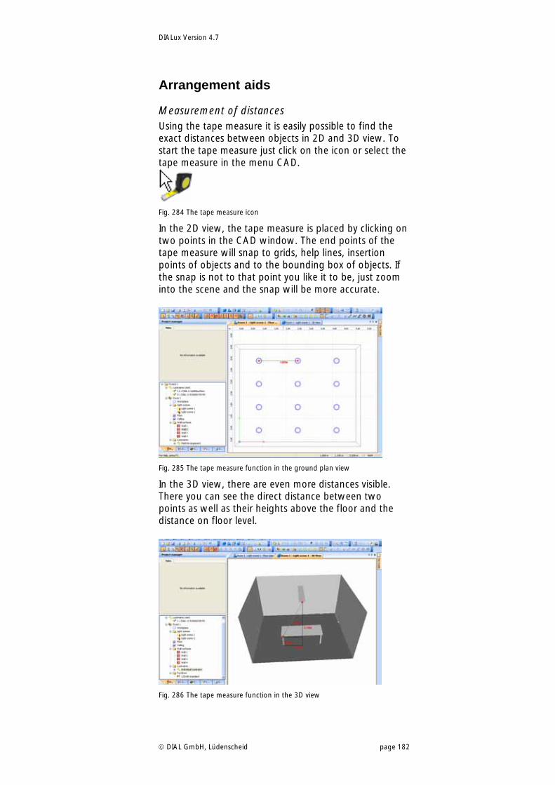
DIALux Version 4.7
DIAL GmbH, Lüdenscheid page 182
Arrangement aids
Measurement of distances Using the tape measure it is easily possible to find the exact distances between objects in 2D and 3D view. To start the tape measure just click on the icon or select the tape measure in the menu CAD.
Fig. 284 The tape measure icon
In the 2D view, the tape measure is placed by clicking on two points in the CAD window. The end points of the tape measure will snap to grids, help lines, insertion points of objects and to the bounding box of objects. If the snap is not to that point you like it to be, just zoom into the scene and the snap will be more accurate.
Fig. 285 The tape measure function in the ground plan view
In the 3D view, there are even more distances visible. There you can see the direct distance between two points as well as their heights above the floor and the distance on floor level.
Fig. 286 The tape measure function in the 3D view
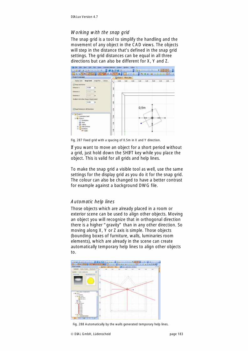
DIALux Version 4.7
DIAL GmbH, Lüdenscheid page 183
Working with the snap grid The snap grid is a tool to simplify the handling and the movement of any object in the CAD views. The objects will step in the distance that’s defined in the snap grid settings. The grid distances can be equal in all three directions but can also be different for X, Y and Z.
Fig. 287 Fixed grid with a spacing of 0.5m in X and Y direction.
If you want to move an object for a short period without a grid, just hold down the SHIFT key while you place the object. This is valid for all grids and help lines. To make the snap grid a visible tool as well, use the same settings for the display grid as you do it for the snap grid. The colour can also be changed to have a better contrast for example against a background DWG file.
Automatic help lines Those objects which are already placed in a room or exterior scene can be used to align other objects. Moving an object you will recognize that in orthogonal direction there is a higher “gravity” than in any other direction. So moving along X, Y or Z axis is simple. Those objects (bounding boxes of furniture, walls, luminaries room elements), which are already in the scene can create automatically temporary help lines to align other objects to.
Fig. 288 Automatically by the walls generated temporary help lines.
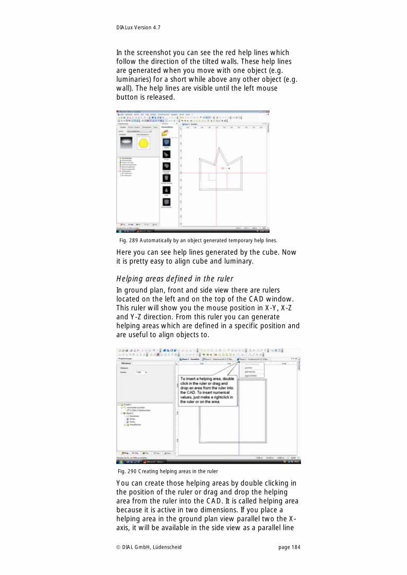
DIALux Version 4.7
DIAL GmbH, Lüdenscheid page 184
In the screenshot you can see the red help lines which follow the direction of the tilted walls. These help lines are generated when you move with one object (e.g. luminaries) for a short while above any other object (e.g. wall). The help lines are visible until the left mouse button is released.
Fig. 289 Automatically by an object generated temporary help lines.
Here you can see help lines generated by the cube. Now it is pretty easy to align cube and luminary.
Helping areas defined in the ruler In ground plan, front and side view there are rulers located on the left and on the top of the CAD window. This ruler will show you the mouse position in X-Y, X-Z and Y-Z direction. From this ruler you can generate helping areas which are defined in a specific position and are useful to align objects to.
Fig. 290 Creating helping areas in the ruler
You can create those helping areas by double clicking in the position of the ruler or drag and drop the helping area from the ruler into the CAD. It is called helping area because it is active in two dimensions. If you place a helping area in the ground plan view parallel two the X-axis, it will be available in the side view as a parallel line
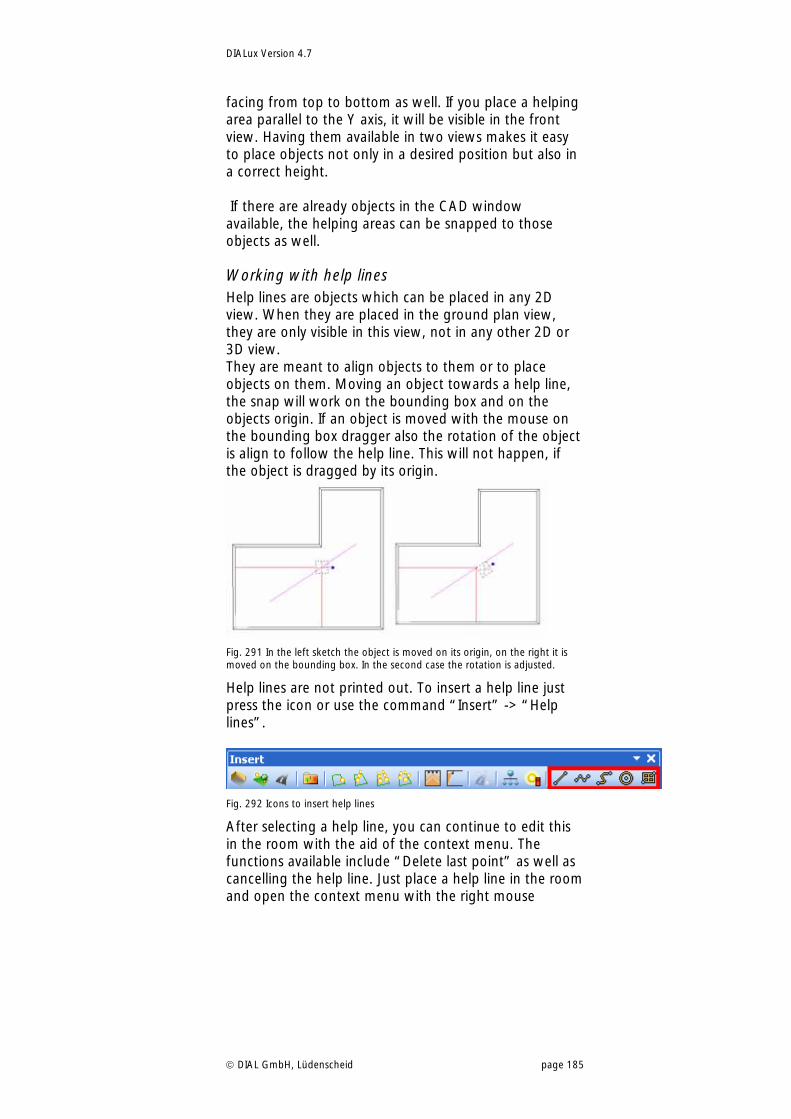
DIALux Version 4.7
DIAL GmbH, Lüdenscheid page 185
facing from top to bottom as well. If you place a helping area parallel to the Y axis, it will be visible in the front view. Having them available in two views makes it easy to place objects not only in a desired position but also in a correct height. If there are already objects in the CAD window available, the helping areas can be snapped to those objects as well.
Working with help lines Help lines are objects which can be placed in any 2D view. When they are placed in the ground plan view, they are only visible in this view, not in any other 2D or 3D view. They are meant to align objects to them or to place objects on them. Moving an object towards a help line, the snap will work on the bounding box and on the objects origin. If an object is moved with the mouse on the bounding box dragger also the rotation of the object is align to follow the help line. This will not happen, if the object is dragged by its origin.
Fig. 291 In the left sketch the object is moved on its origin, on the right it is moved on the bounding box. In the second case the rotation is adjusted.
Help lines are not printed out. To insert a help line just press the icon or use the command “Insert” -> “Help lines”.
Fig. 292 Icons to insert help lines
After selecting a help line, you can continue to edit this in the room with the aid of the context menu. The functions available include “Delete last point” as well as cancelling the help line. Just place a help line in the room and open the context menu with the right mouse
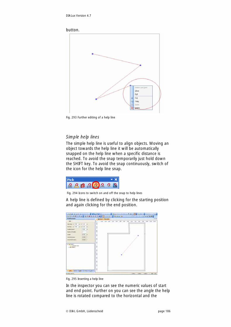
DIALux Version 4.7
DIAL GmbH, Lüdenscheid page 186
button.
Fig. 293 Further editing of a help line
Simple help lines The simple help line is useful to align objects. Moving an object towards the help line it will be automatically snapped on the help line when a specific distance is reached. To avoid the snap temporarily just hold down the SHIFT key. To avoid the snap continuously, switch of the icon for the help line snap.
Fig. 294 Icons to switch on and off the snap to help lines
A help line is defined by clicking for the starting position and again clicking for the end position.
Fig. 295 Inserting a help line
In the inspector you can see the numeric values of start and end point. Further on you can see the angle the help line is rotated compared to the horizontal and the
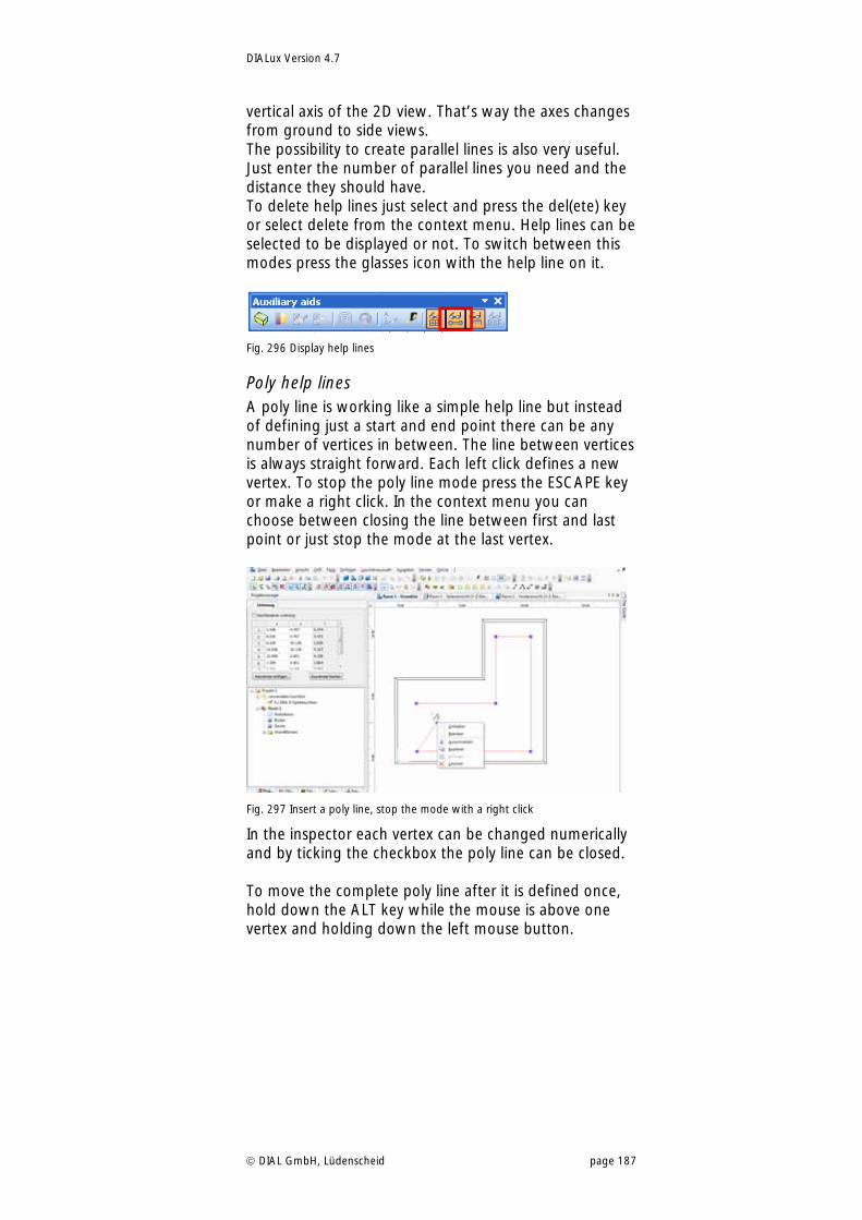
DIALux Version 4.7
DIAL GmbH, Lüdenscheid page 187
vertical axis of the 2D view. That’s way the axes changes from ground to side views. The possibility to create parallel lines is also very useful. Just enter the number of parallel lines you need and the distance they should have. To delete help lines just select and press the del(ete) key or select delete from the context menu. Help lines can be selected to be displayed or not. To switch between this modes press the glasses icon with the help line on it.
Fig. 296 Display help lines
Poly help lines A poly line is working like a simple help line but instead of defining just a start and end point there can be any number of vertices in between. The line between vertices is always straight forward. Each left click defines a new vertex. To stop the poly line mode press the ESCAPE key or make a right click. In the context menu you can choose between closing the line between first and last point or just stop the mode at the last vertex.
Fig. 297 Insert a poly line, stop the mode with a right click
In the inspector each vertex can be changed numerically and by ticking the checkbox the poly line can be closed. To move the complete poly line after it is defined once, hold down the ALT key while the mouse is above one vertex and holding down the left mouse button.
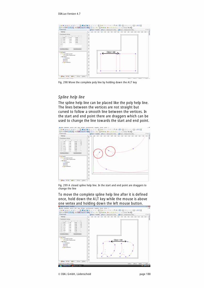
DIALux Version 4.7
DIAL GmbH, Lüdenscheid page 188
Fig. 298 Move the complete poly line by holding down the ALT key
Spline help line The spline help line can be placed like the poly help line. The lines between the vertices are not straight but curved to follow a smooth line between the vertices. In the start and end point there are draggers which can be used to change the line towards the start and end point.
Fig. 299 A closed spline help line. In the start and end point are draggers to change the line
To move the complete spline help line after it is defined once, hold down the ALT key while the mouse is above one vertex and holding down the left mouse button.
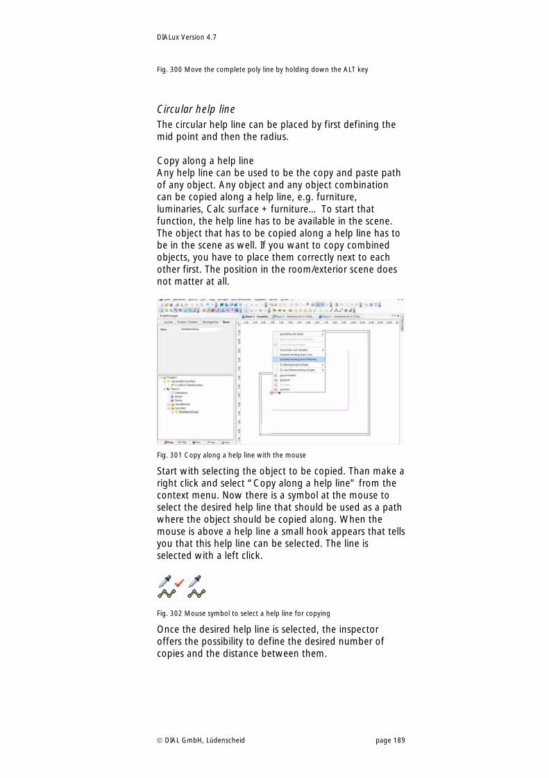
DIALux Version 4.7
DIAL GmbH, Lüdenscheid page 189
Fig. 300 Move the complete poly line by holding down the ALT key
Circular help line The circular help line can be placed by first defining the mid point and then the radius. Copy along a help line Any help line can be used to be the copy and paste path of any object. Any object and any object combination can be copied along a help line, e.g. furniture, luminaries, Calc surface + furniture… To start that function, the help line has to be available in the scene. The object that has to be copied along a help line has to be in the scene as well. If you want to copy combined objects, you have to place them correctly next to each other first. The position in the room/exterior scene does not matter at all.
Fig. 301 Copy along a help line with the mouse
Start with selecting the object to be copied. Than make a right click and select “Copy along a help line” from the context menu. Now there is a symbol at the mouse to select the desired help line that should be used as a path where the object should be copied along. When the mouse is above a help line a small hook appears that tells you that this help line can be selected. The line is selected with a left click.
Fig. 302 Mouse symbol to select a help line for copying
Once the desired help line is selected, the inspector offers the possibility to define the desired number of copies and the distance between them.
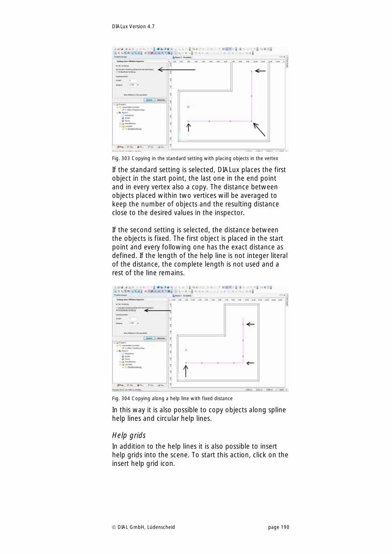
DIALux Version 4.7
DIAL GmbH, Lüdenscheid page 190
Fig. 303 Copying in the standard setting with placing objects in the vertex
If the standard setting is selected, DIALux places the first object in the start point, the last one in the end point and in every vertex also a copy. The distance between objects placed within two vertices will be averaged to keep the number of objects and the resulting distance close to the desired values in the inspector. If the second setting is selected, the distance between the objects is fixed. The first object is placed in the start point and every following one has the exact distance as defined. If the length of the help line is not integer literal of the distance, the complete length is not used and a rest of the line remains.
Fig. 304 Copying along a help line with fixed distance
In this way it is also possible to copy objects along spline help lines and circular help lines.
Help grids In addition to the help lines it is also possible to insert help grids into the scene. To start this action, click on the insert help grid icon.
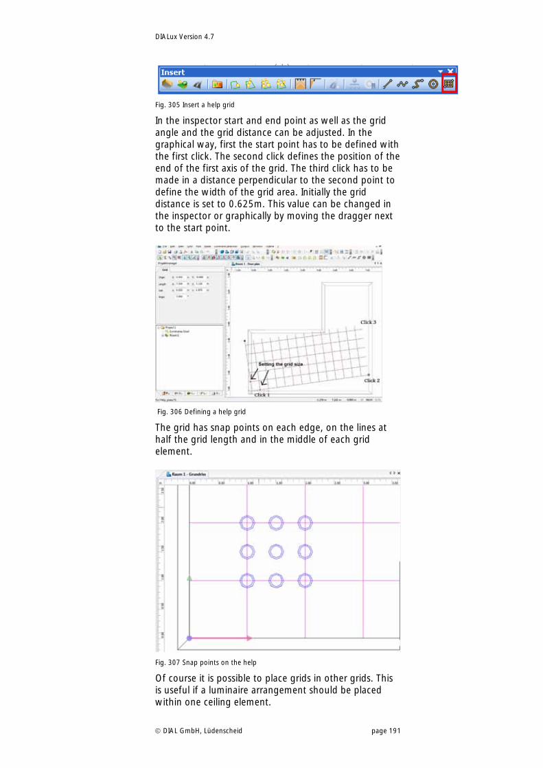
DIALux Version 4.7
DIAL GmbH, Lüdenscheid page 191
Fig. 305 Insert a help grid
In the inspector start and end point as well as the grid angle and the grid distance can be adjusted. In the graphical way, first the start point has to be defined with the first click. The second click defines the position of the end of the first axis of the grid. The third click has to be made in a distance perpendicular to the second point to define the width of the grid area. Initially the grid distance is set to 0.625m. This value can be changed in the inspector or graphically by moving the dragger next to the start point.
Fig. 306 Defining a help grid
The grid has snap points on each edge, on the lines at half the grid length and in the middle of each grid element.
Fig. 307 Snap points on the help
Of course it is possible to place grids in other grids. This is useful if a luminaire arrangement should be placed within one ceiling element.
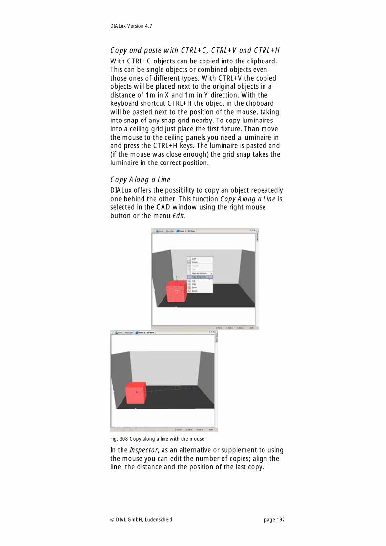
DIALux Version 4.7
DIAL GmbH, Lüdenscheid page 192
Copy and paste with CTRL+C, CTRL+V and CTRL+H With CTRL+C objects can be copied into the clipboard. This can be single objects or combined objects even those ones of different types. With CTRL+V the copied objects will be placed next to the original objects in a distance of 1m in X and 1m in Y direction. With the keyboard shortcut CTRL+H the object in the clipboard will be pasted next to the position of the mouse, taking into snap of any snap grid nearby. To copy luminaires into a ceiling grid just place the first fixture. Than move the mouse to the ceiling panels you need a luminaire in and press the CTRL+H keys. The luminaire is pasted and (if the mouse was close enough) the grid snap takes the luminaire in the correct position.
Copy Along a Line DIALux offers the possibility to copy an object repeatedly one behind the other. This function Copy Along a Line is selected in the CAD window using the right mouse button or the menu Edit.
Fig. 308 Copy along a line with the mouse
In the Inspector, as an alternative or supplement to using the mouse you can edit the number of copies; align the line, the distance and the position of the last copy.
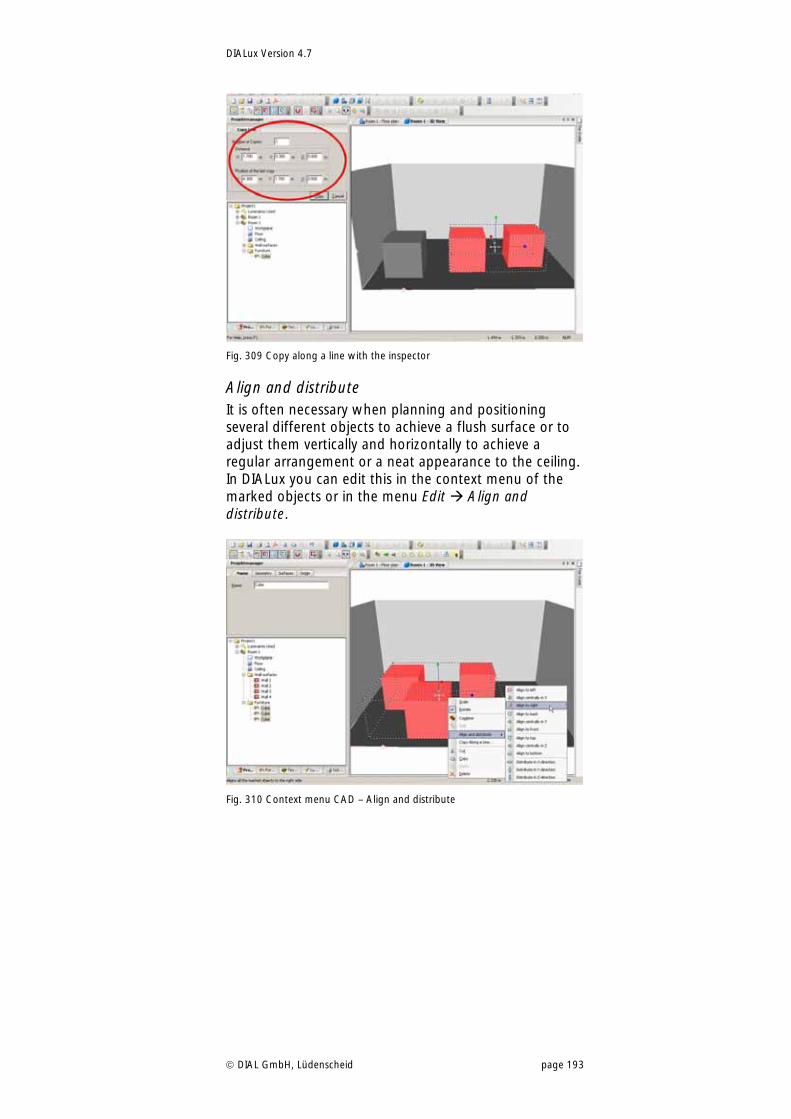
DIALux Version 4.7
DIAL GmbH, Lüdenscheid page 193
Fig. 309 Copy along a line with the inspector
Align and distribute It is often necessary when planning and positioning several different objects to achieve a flush surface or to adjust them vertically and horizontally to achieve a regular arrangement or a neat appearance to the ceiling. In DIALux you can edit this in the context menu of the marked objects or in the menu Edit Align and distribute.
Fig. 310 Context menu CAD – Align and distribute
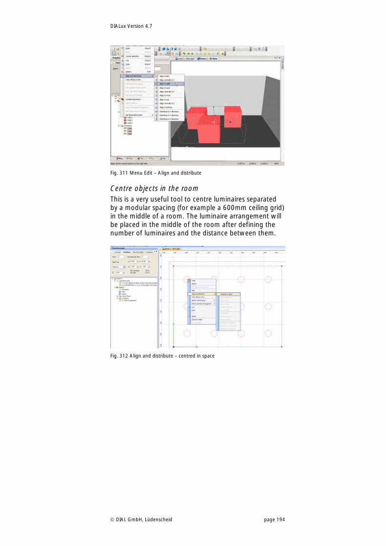
DIALux Version 4.7
DIAL GmbH, Lüdenscheid page 194
Fig. 311 Menu Edit – Align and distribute
Centre objects in the room This is a very useful tool to centre luminaires separated by a modular spacing (for example a 600mm ceiling grid) in the middle of a room. The luminaire arrangement will be placed in the middle of the room after defining the number of luminaires and the distance between them.
Fig. 312 Align and distribute – centred in space
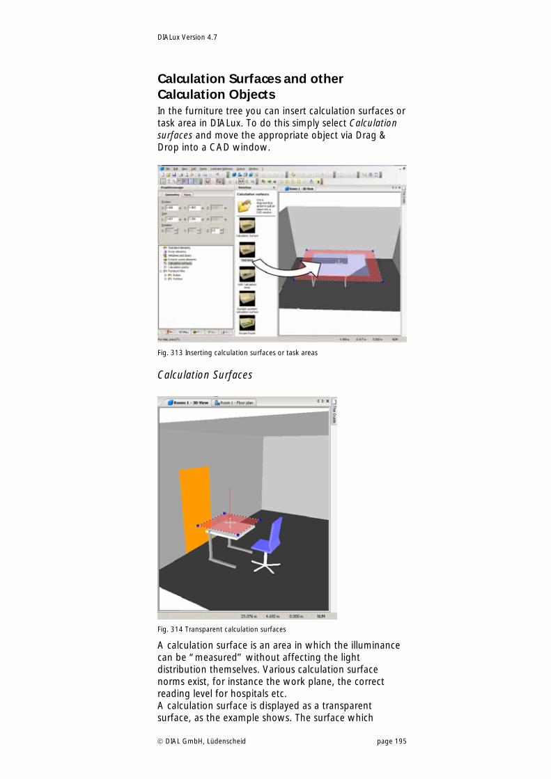
DIALux Version 4.7
DIAL GmbH, Lüdenscheid page 195
Calculation Surfaces and other Calculation Objects In the furniture tree you can insert calculation surfaces or task area in DIALux. To do this simply select Calculation surfaces and move the appropriate object via Drag & Drop into a CAD window.
Fig. 313 Inserting calculation surfaces or task areas
Calculation Surfaces
Fig. 314 Transparent calculation surfaces
A calculation surface is an area in which the illuminance can be “measured” without affecting the light distribution themselves. Various calculation surface norms exist, for instance the work plane, the correct reading level for hospitals etc. A calculation surface is displayed as a transparent surface, as the example shows. The surface which

DIALux Version 4.7
DIAL GmbH, Lüdenscheid page 196
appears transparent is the surface which provides the calculation results. The surface is invisible when viewed from the other side. No results are calculated for the invisible side. These objects can be scaled and rotated like all other furniture. Exception: windows and doors are always plane-parallel to the respective wall.
Calculation surfaces for different types of illuminance The calculation surfaces in DIALux can now calculate different types of illuminance. As well as calculating the normal, namely the planar illuminance, perpendicular to the receiving plane, it is now possible to explicitly calculate vertical planar, horizontal planar and camera directed planar illuminance and also semi-cylindrical and cylindrical illuminance.
Fig. 315 Different types of illuminance
Fig. 316 Property Page of calculation surface – Selection of the types of illuminance
Penetration If calculation areas are penetrated by furniture (e.g. cupboard and working surface) these are now
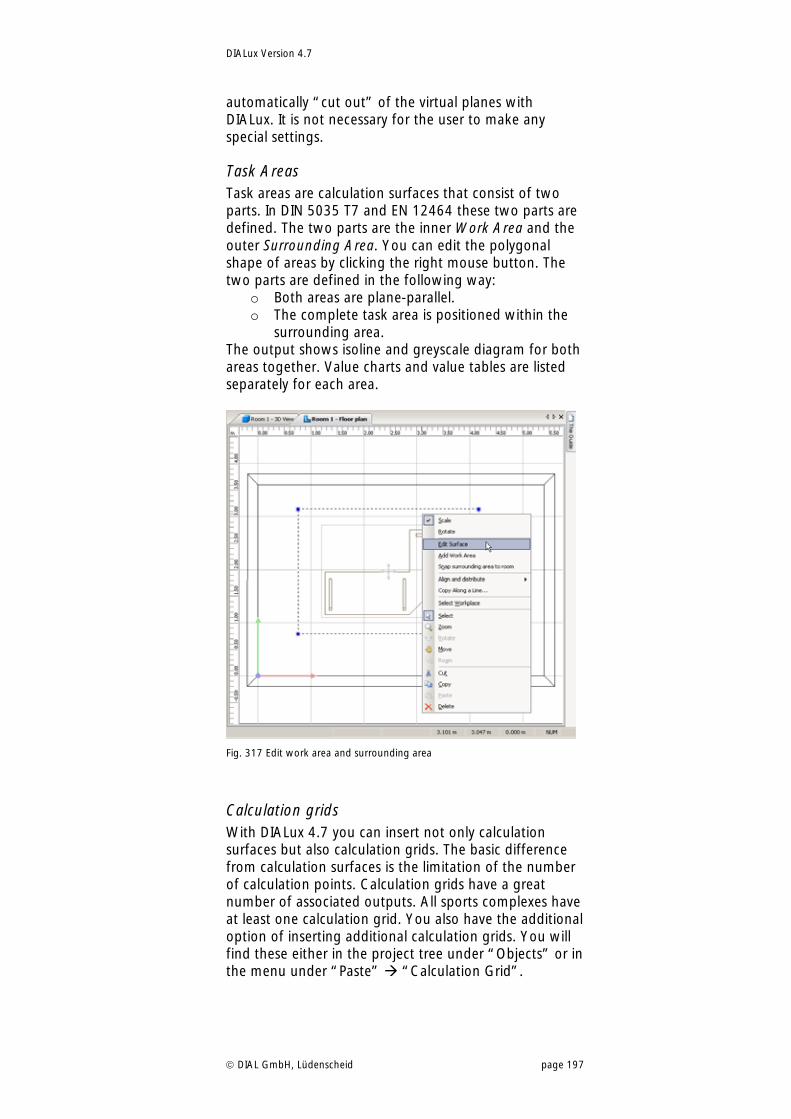
DIALux Version 4.7
DIAL GmbH, Lüdenscheid page 197
automatically “cut out” of the virtual planes with DIALux. It is not necessary for the user to make any special settings.
Task Areas Task areas are calculation surfaces that consist of two parts. In DIN 5035 T7 and EN 12464 these two parts are defined. The two parts are the inner Work Area and the outer Surrounding Area. You can edit the polygonal shape of areas by clicking the right mouse button. The two parts are defined in the following way:
o Both areas are plane-parallel. o The complete task area is positioned within the
surrounding area. The output shows isoline and greyscale diagram for both areas together. Value charts and value tables are listed separately for each area.
Fig. 317 Edit work area and surrounding area
Calculation grids With DIALux 4.7 you can insert not only calculation surfaces but also calculation grids. The basic difference from calculation surfaces is the limitation of the number of calculation points. Calculation grids have a great number of associated outputs. All sports complexes have at least one calculation grid. You also have the additional option of inserting additional calculation grids. You will find these either in the project tree under “Objects” or in the menu under “Paste” “Calculation Grid”.
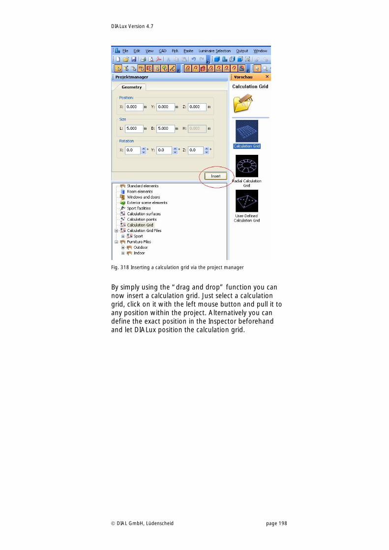
DIALux Version 4.7
DIAL GmbH, Lüdenscheid page 198
Fig. 318 Inserting a calculation grid via the project manager
By simply using the “drag and drop” function you can now insert a calculation grid. Just select a calculation grid, click on it with the left mouse button and pull it to any position within the project. Alternatively you can define the exact position in the Inspector beforehand and let DIALux position the calculation grid.
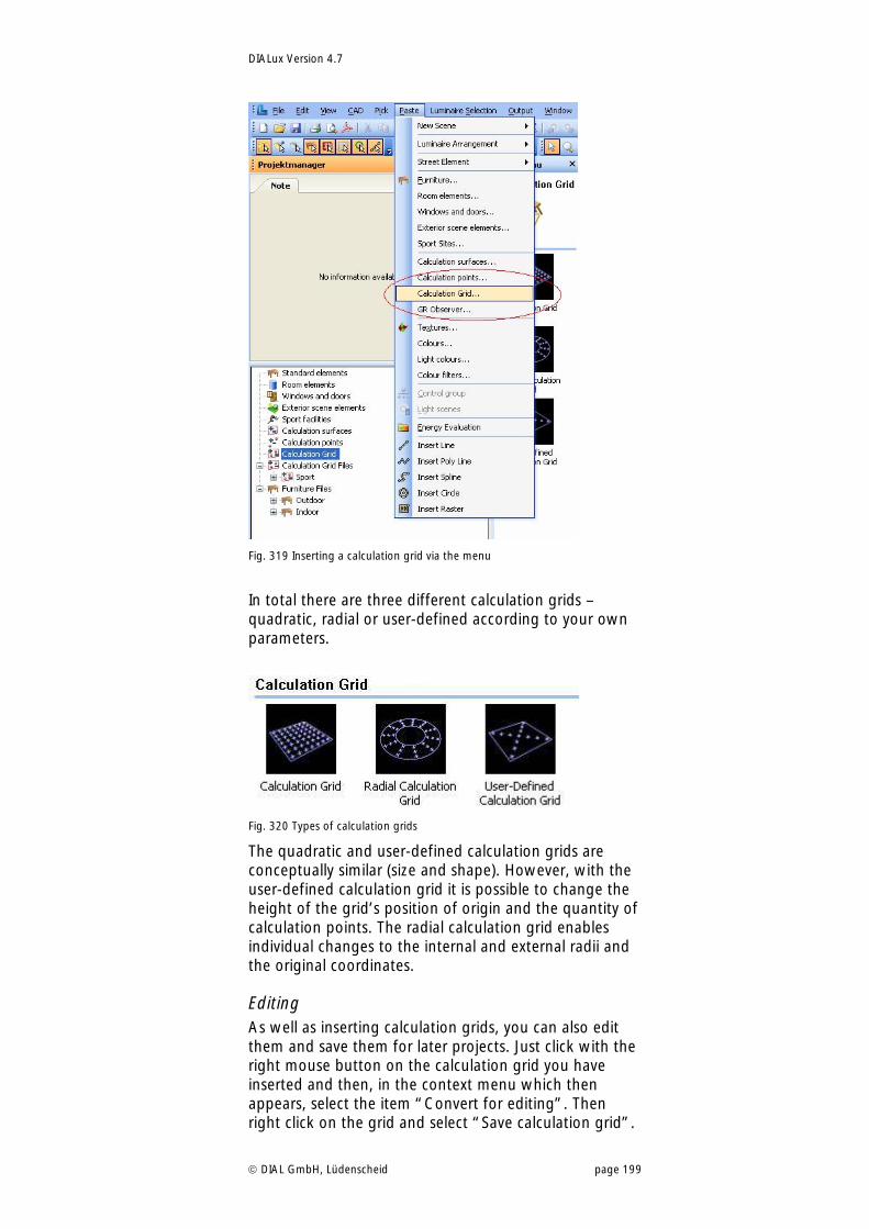
DIALux Version 4.7
DIAL GmbH, Lüdenscheid page 199
Fig. 319 Inserting a calculation grid via the menu
In total there are three different calculation grids – quadratic, radial or user-defined according to your own parameters.
Fig. 320 Types of calculation grids
The quadratic and user-defined calculation grids are conceptually similar (size and shape). However, with the user-defined calculation grid it is possible to change the height of the grid’s position of origin and the quantity of calculation points. The radial calculation grid enables individual changes to the internal and external radii and the original coordinates.
Editing As well as inserting calculation grids, you can also edit them and save them for later projects. Just click with the right mouse button on the calculation grid you have inserted and then, in the context menu which then appears, select the item “Convert for editing”. Then right click on the grid and select “Save calculation grid”.
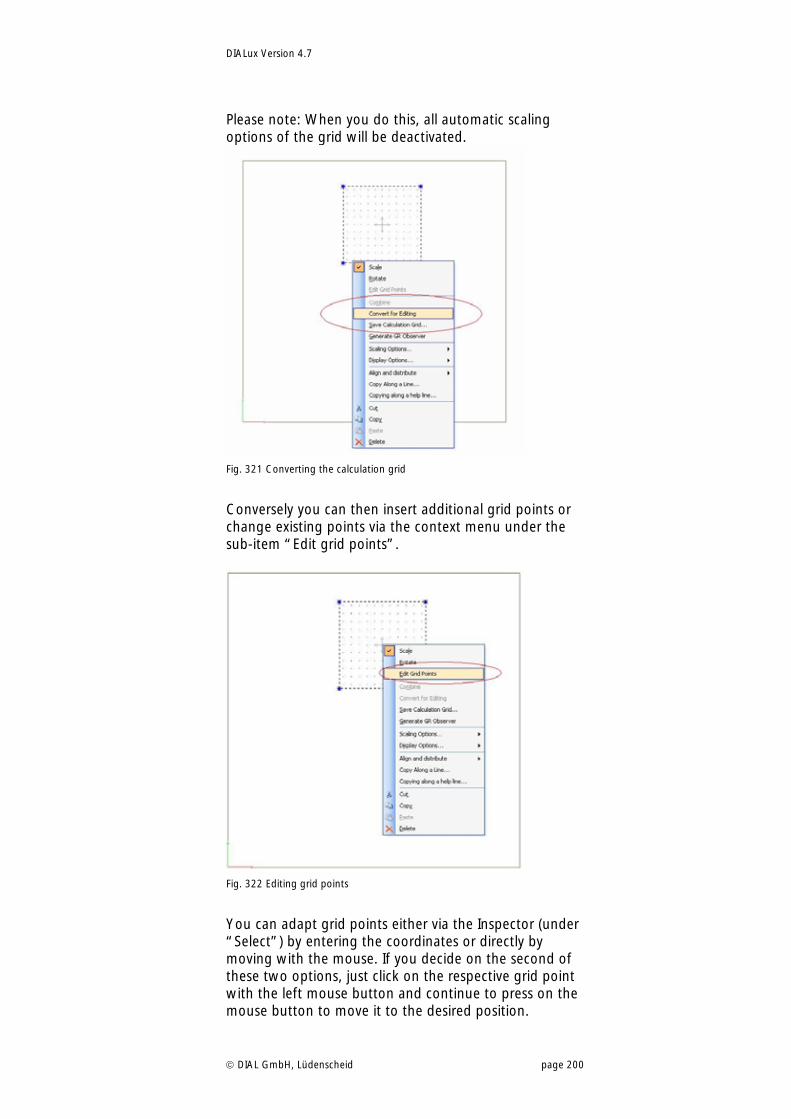
DIALux Version 4.7
DIAL GmbH, Lüdenscheid page 200
Please note: When you do this, all automatic scaling options of the grid will be deactivated.
Fig. 321 Converting the calculation grid
Conversely you can then insert additional grid points or change existing points via the context menu under the sub-item “Edit grid points”.
Fig. 322 Editing grid points
You can adapt grid points either via the Inspector (under “Select”) by entering the coordinates or directly by moving with the mouse. If you decide on the second of these two options, just click on the respective grid point with the left mouse button and continue to press on the mouse button to move it to the desired position.
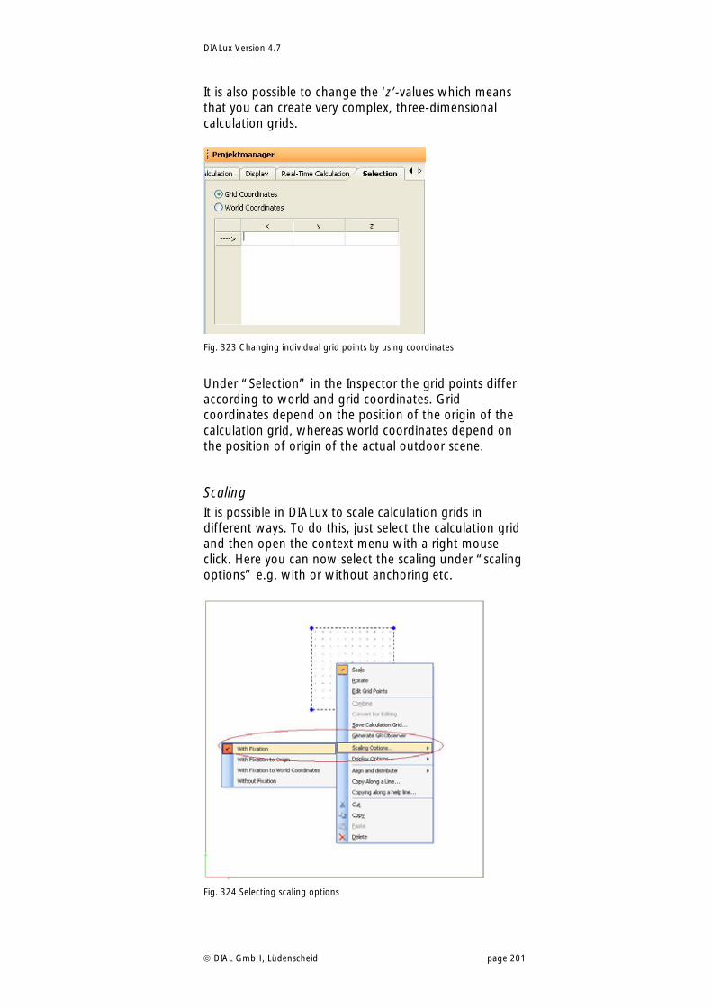
DIALux Version 4.7
DIAL GmbH, Lüdenscheid page 201
It is also possible to change the ‘z’-values which means that you can create very complex, three-dimensional calculation grids.
Fig. 323 Changing individual grid points by using coordinates
Under “Selection” in the Inspector the grid points differ according to world and grid coordinates. Grid coordinates depend on the position of the origin of the calculation grid, whereas world coordinates depend on the position of origin of the actual outdoor scene.
Scaling It is possible in DIALux to scale calculation grids in different ways. To do this, just select the calculation grid and then open the context menu with a right mouse click. Here you can now select the scaling under “scaling options” e.g. with or without anchoring etc.
Fig. 324 Selecting scaling options
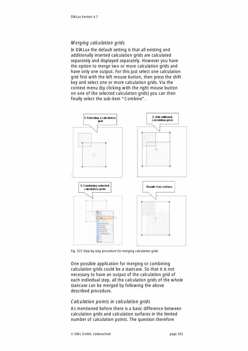
DIALux Version 4.7
DIAL GmbH, Lüdenscheid page 202
Merging calculation grids In DIALux the default setting is that all existing and additionally inserted calculation grids are calculated separately and displayed separately. However you have the option to merge two or more calculation grids and have only one output. For this just select one calculation grid first with the left mouse button, then press the shift key and select one or more calculation grids. Via the context menu (by clicking with the right mouse button on one of the selected calculation grids) you can then finally select the sub-item “Combine”.
Fig. 325 Step-by-step procedure for merging calculation grids
One possible application for merging or combining calculation grids could be a staircase. So that it is not necessary to have an output of the calculation grid of each individual step, all the calculation grids of the whole staircase can be merged by following the above described procedure.
Calculation points in calculation grids As mentioned before there is a basic difference between calculation grids and calculation surfaces in the limited number of calculation points. The question therefore
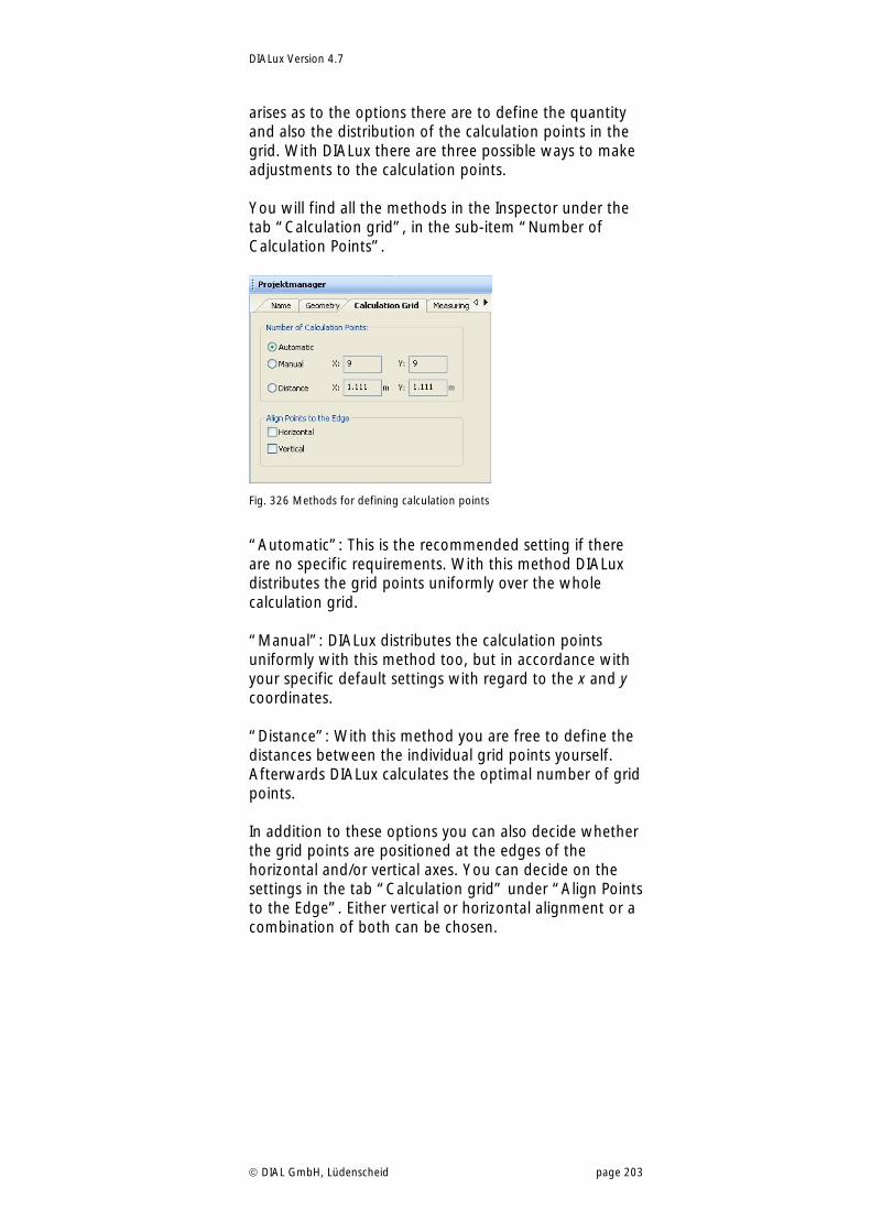
DIALux Version 4.7
DIAL GmbH, Lüdenscheid page 203
arises as to the options there are to define the quantity and also the distribution of the calculation points in the grid. With DIALux there are three possible ways to make adjustments to the calculation points. You will find all the methods in the Inspector under the tab “Calculation grid”, in the sub-item “Number of Calculation Points”.
Fig. 326 Methods for defining calculation points
“Automatic”: This is the recommended setting if there are no specific requirements. With this method DIALux distributes the grid points uniformly over the whole calculation grid. “Manual”: DIALux distributes the calculation points uniformly with this method too, but in accordance with your specific default settings with regard to the x and y coordinates. “Distance”: With this method you are free to define the distances between the individual grid points yourself. Afterwards DIALux calculates the optimal number of grid points. In addition to these options you can also decide whether the grid points are positioned at the edges of the horizontal and/or vertical axes. You can decide on the settings in the tab “Calculation grid” under “Align Points to the Edge”. Either vertical or horizontal alignment or a combination of both can be chosen.
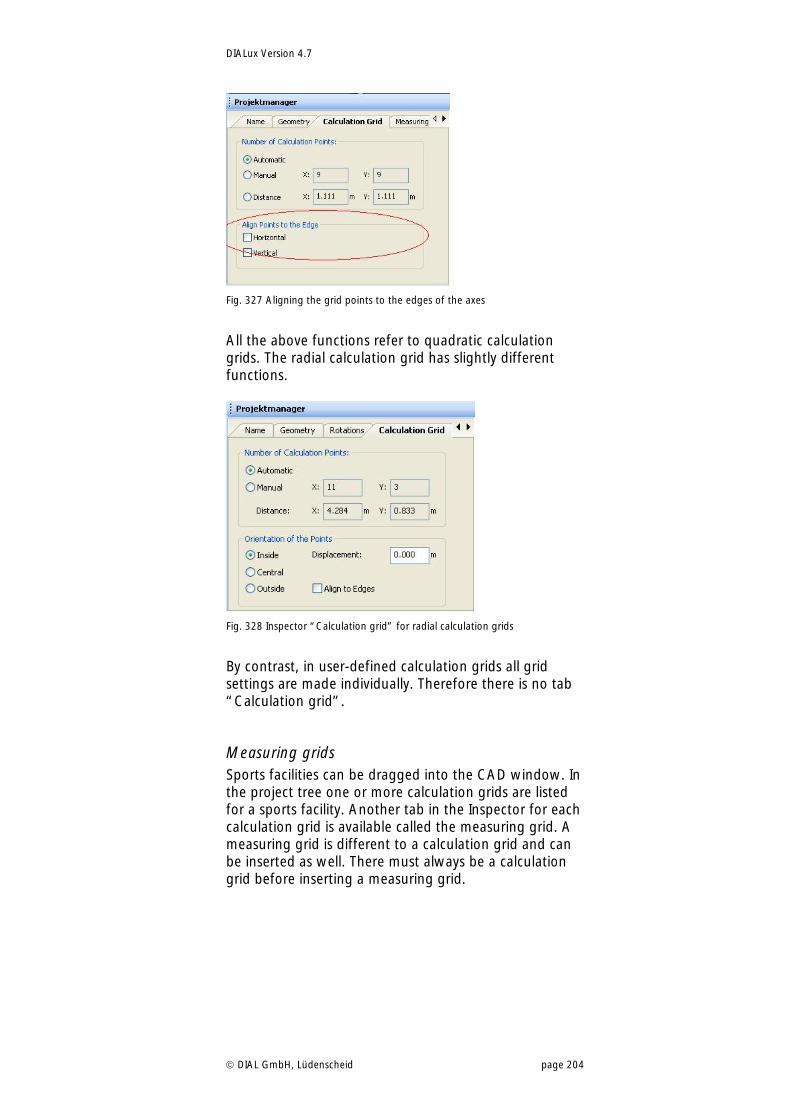
DIALux Version 4.7
DIAL GmbH, Lüdenscheid page 204
Fig. 327 Aligning the grid points to the edges of the axes
All the above functions refer to quadratic calculation grids. The radial calculation grid has slightly different functions.
Fig. 328 Inspector “Calculation grid” for radial calculation grids
By contrast, in user-defined calculation grids all grid settings are made individually. Therefore there is no tab “Calculation grid”.
Measuring grids Sports facilities can be dragged into the CAD window. In the project tree one or more calculation grids are listed for a sports facility. Another tab in the Inspector for each calculation grid is available called the measuring grid. A measuring grid is different to a calculation grid and can be inserted as well. There must always be a calculation grid before inserting a measuring grid.
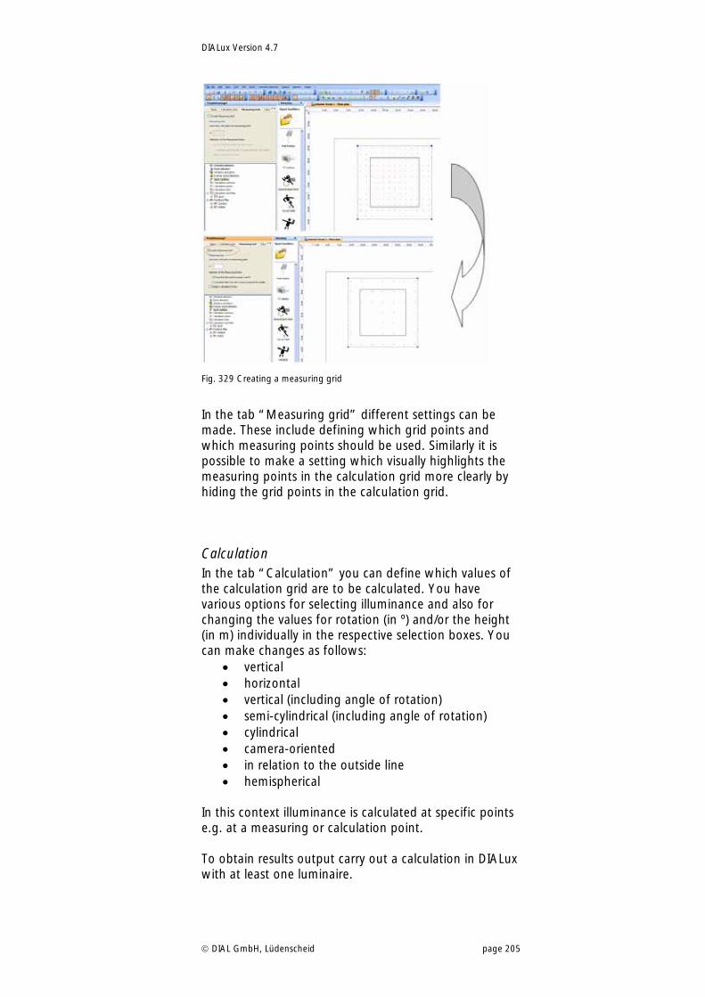
DIALux Version 4.7
DIAL GmbH, Lüdenscheid page 205
Fig. 329 Creating a measuring grid
In the tab “Measuring grid” different settings can be made. These include defining which grid points and which measuring points should be used. Similarly it is possible to make a setting which visually highlights the measuring points in the calculation grid more clearly by hiding the grid points in the calculation grid.
Calculation In the tab “Calculation” you can define which values of the calculation grid are to be calculated. You have various options for selecting illuminance and also for changing the values for rotation (in º) and/or the height (in m) individually in the respective selection boxes. You can make changes as follows:
vertical horizontal vertical (including angle of rotation) semi-cylindrical (including angle of rotation) cylindrical camera-oriented in relation to the outside line hemispherical
In this context illuminance is calculated at specific points e.g. at a measuring or calculation point. To obtain results output carry out a calculation in DIALux with at least one luminaire.
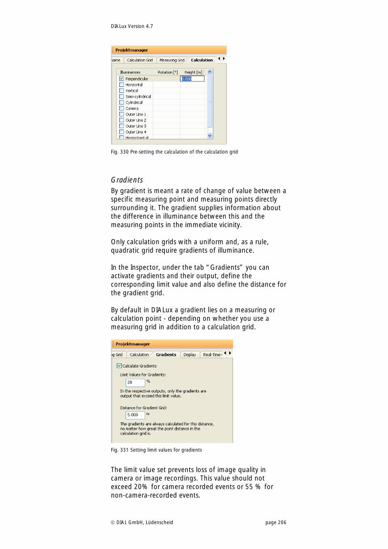
DIALux Version 4.7
DIAL GmbH, Lüdenscheid page 206
Fig. 330 Pre-setting the calculation of the calculation grid
Gradients By gradient is meant a rate of change of value between a specific measuring point and measuring points directly surrounding it. The gradient supplies information about the difference in illuminance between this and the measuring points in the immediate vicinity. Only calculation grids with a uniform and, as a rule, quadratic grid require gradients of illuminance. In the Inspector, under the tab “Gradients” you can activate gradients and their output, define the corresponding limit value and also define the distance for the gradient grid. By default in DIALux a gradient lies on a measuring or calculation point - depending on whether you use a measuring grid in addition to a calculation grid.
Fig. 331 Setting limit values for gradients
The limit value set prevents loss of image quality in camera or image recordings. This value should not exceed 20% for camera recorded events or 55 % for non-camera-recorded events.
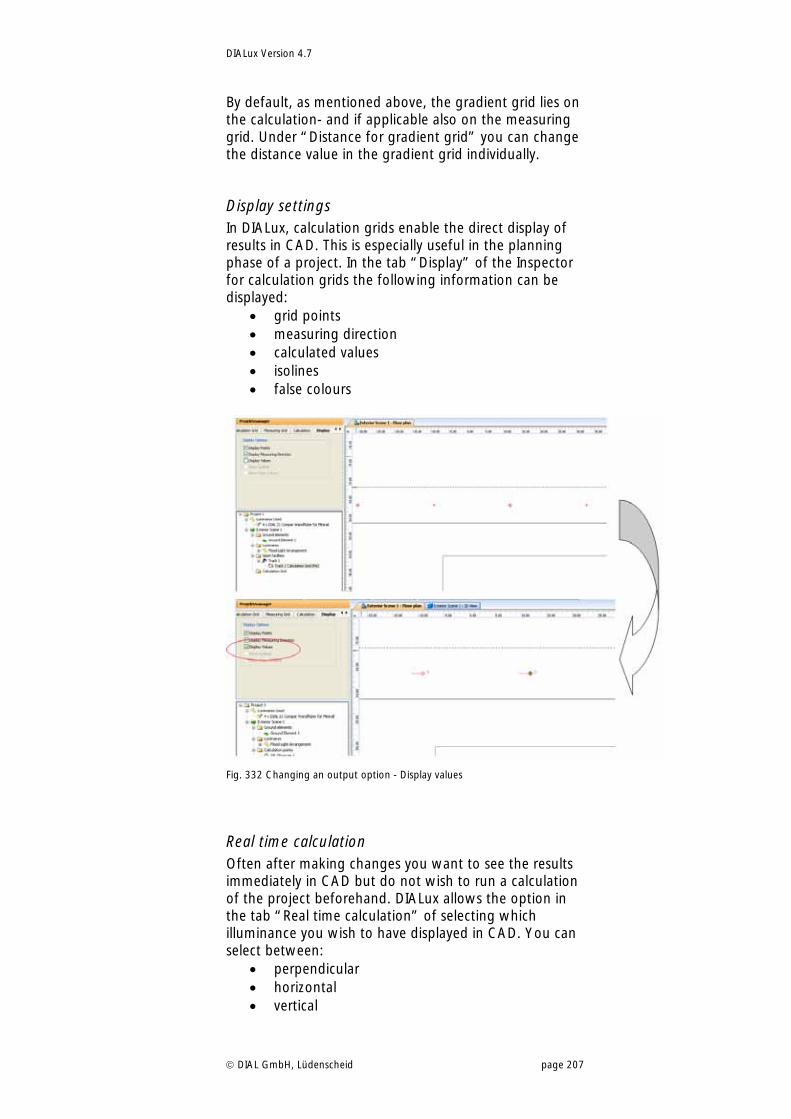
DIALux Version 4.7
DIAL GmbH, Lüdenscheid page 207
By default, as mentioned above, the gradient grid lies on the calculation- and if applicable also on the measuring grid. Under “Distance for gradient grid” you can change the distance value in the gradient grid individually.
Display settings In DIALux, calculation grids enable the direct display of results in CAD. This is especially useful in the planning phase of a project. In the tab “Display” of the Inspector for calculation grids the following information can be displayed:
grid points measuring direction calculated values isolines false colours
Fig. 332 Changing an output option - Display values
Real time calculation Often after making changes you want to see the results immediately in CAD but do not wish to run a calculation of the project beforehand. DIALux allows the option in the tab “Real time calculation” of selecting which illuminance you wish to have displayed in CAD. You can select between:
perpendicular horizontal vertical
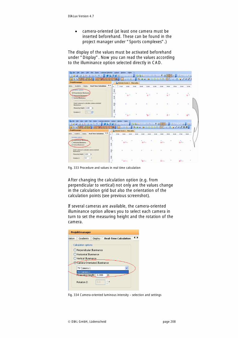
DIALux Version 4.7
DIAL GmbH, Lüdenscheid page 208
camera-oriented (at least one camera must be inserted beforehand. These can be found in the project manager under “Sports complexes”.)
The display of the values must be activated beforehand under “Display”. Now you can read the values according to the illuminance option selected directly in CAD.
Fig. 333 Procedure and values in real time calculation
After changing the calculation option (e.g. from perpendicular to vertical) not only are the values change in the calculation grid but also the orientation of the calculation points (see previous screenshot). If several cameras are available, the camera-oriented illuminance option allows you to select each camera in turn to set the measuring height and the rotation of the camera.
Fig. 334 Camera-oriented luminous intensity – selection and settings
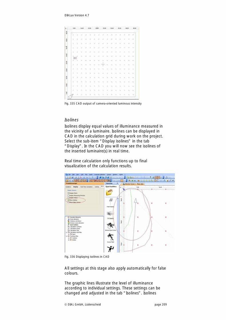
DIALux Version 4.7
DIAL GmbH, Lüdenscheid page 209
Fig. 335 CAD output of camera-oriented luminous intensity
Isolines Isolines display equal values of illuminance measured in the vicinity of a luminaire. Isolines can be displayed in CAD in the calculation grid during work on the project. Select the sub-item “Display isolines” in the tab “Display”. In the CAD you will now see the isolines of the inserted luminaire(s) in real time. Real time calculation only functions up to final visualization of the calculation results.
Fig. 336 Displaying isolines in CAD
All settings at this stage also apply automatically for false colours. The graphic lines illustrate the level of illuminance according to individual settings. These settings can be changed and adjusted in the tab “Isolines”. Isolines
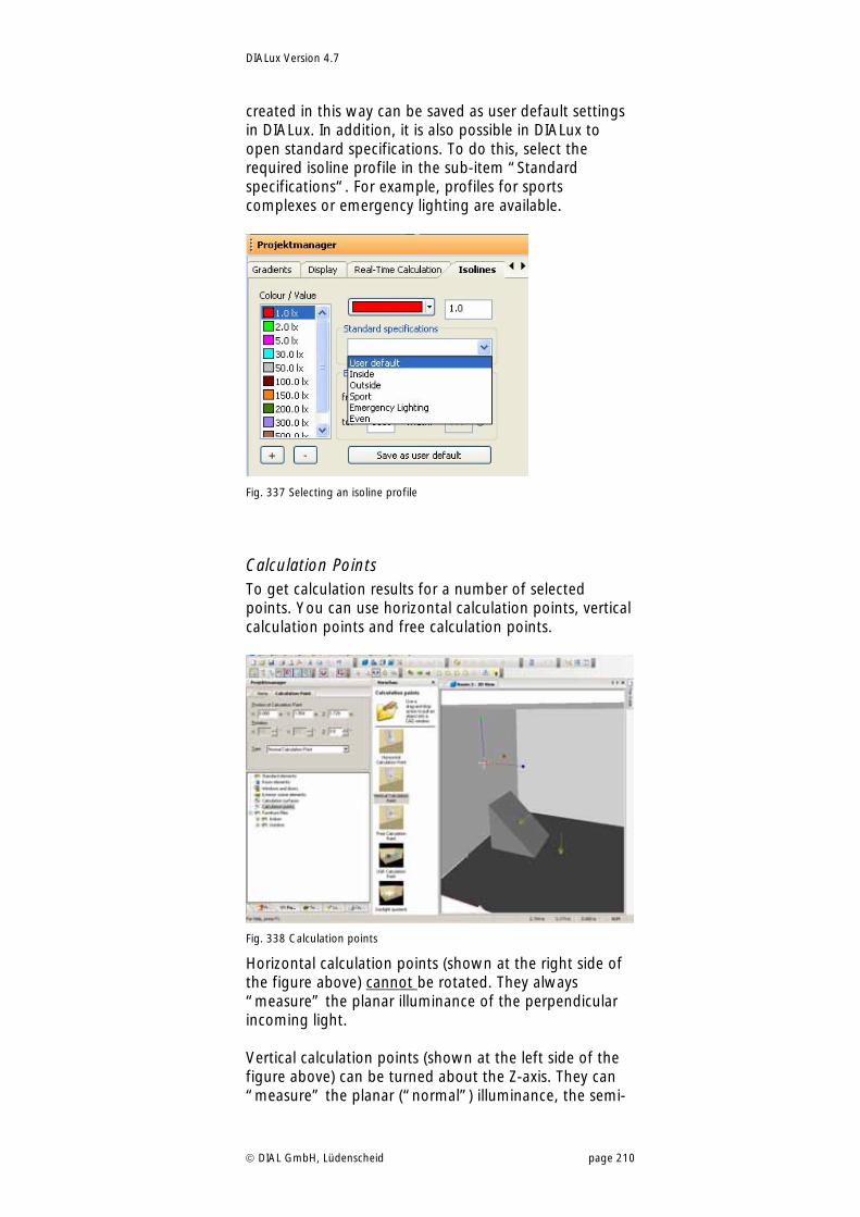
DIALux Version 4.7
DIAL GmbH, Lüdenscheid page 210
created in this way can be saved as user default settings in DIALux. In addition, it is also possible in DIALux to open standard specifications. To do this, select the required isoline profile in the sub-item “Standard specifications“. For example, profiles for sports complexes or emergency lighting are available.
Fig. 337 Selecting an isoline profile
Calculation Points To get calculation results for a number of selected points. You can use horizontal calculation points, vertical calculation points and free calculation points.
Fig. 338 Calculation points
Horizontal calculation points (shown at the right side of the figure above) cannot be rotated. They always “measure” the planar illuminance of the perpendicular incoming light. Vertical calculation points (shown at the left side of the figure above) can be turned about the Z-axis. They can “measure” the planar (“normal”) illuminance, the semi-
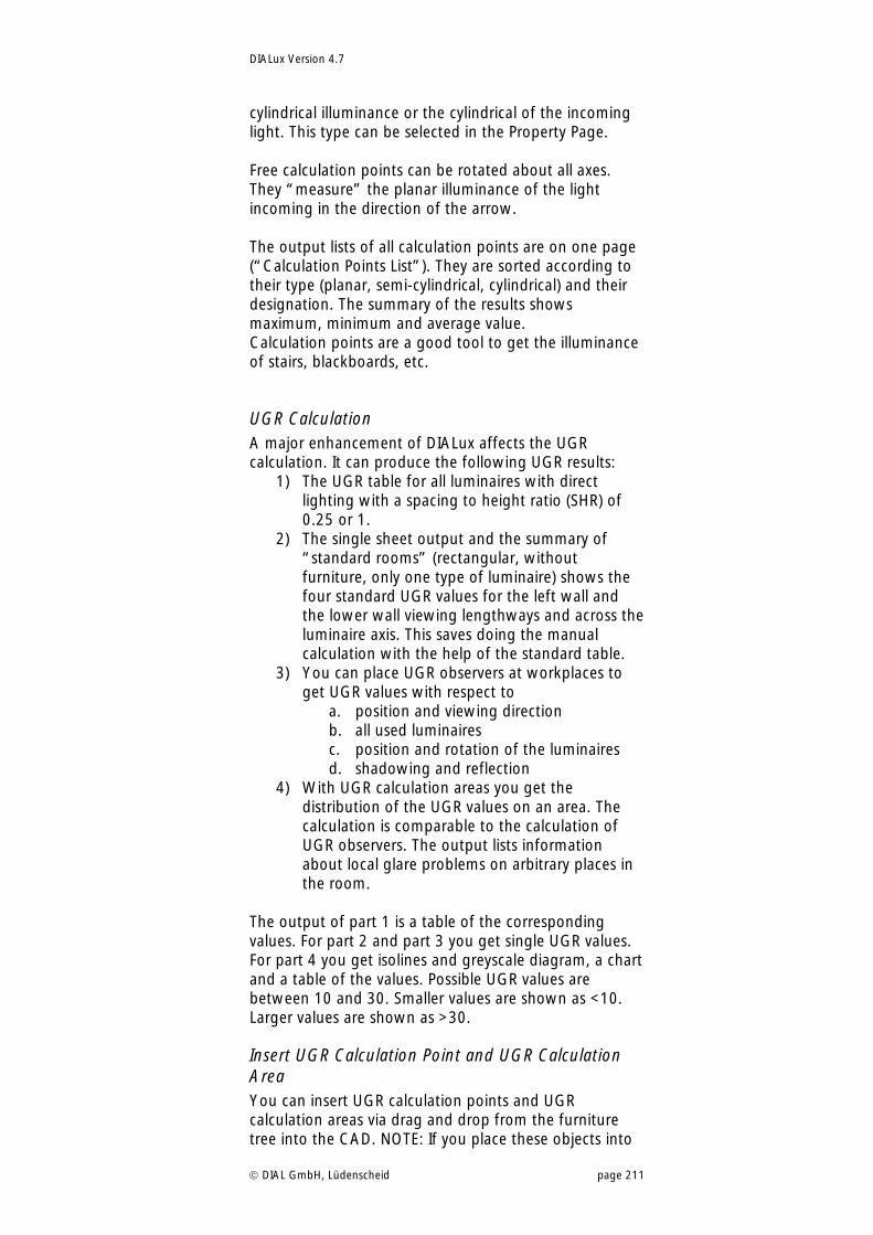
DIALux Version 4.7
DIAL GmbH, Lüdenscheid page 211
cylindrical illuminance or the cylindrical of the incoming light. This type can be selected in the Property Page. Free calculation points can be rotated about all axes. They “measure” the planar illuminance of the light incoming in the direction of the arrow. The output lists of all calculation points are on one page (“Calculation Points List”). They are sorted according to their type (planar, semi-cylindrical, cylindrical) and their designation. The summary of the results shows maximum, minimum and average value. Calculation points are a good tool to get the illuminance of stairs, blackboards, etc.
UGR Calculation A major enhancement of DIALux affects the UGR calculation. It can produce the following UGR results:
1) The UGR table for all luminaires with direct lighting with a spacing to height ratio (SHR) of 0.25 or 1.
2) The single sheet output and the summary of “standard rooms” (rectangular, without furniture, only one type of luminaire) shows the four standard UGR values for the left wall and the lower wall viewing lengthways and across the luminaire axis. This saves doing the manual calculation with the help of the standard table.
3) You can place UGR observers at workplaces to get UGR values with respect to
a. position and viewing direction b. all used luminaires c. position and rotation of the luminaires d. shadowing and reflection
4) With UGR calculation areas you get the distribution of the UGR values on an area. The calculation is comparable to the calculation of UGR observers. The output lists information about local glare problems on arbitrary places in the room.
The output of part 1 is a table of the corresponding values. For part 2 and part 3 you get single UGR values. For part 4 you get isolines and greyscale diagram, a chart and a table of the values. Possible UGR values are between 10 and 30. Smaller values are shown as <10. Larger values are shown as >30.
Insert UGR Calculation Point and UGR Calculation Area You can insert UGR calculation points and UGR calculation areas via drag and drop from the furniture tree into the CAD. NOTE: If you place these objects into
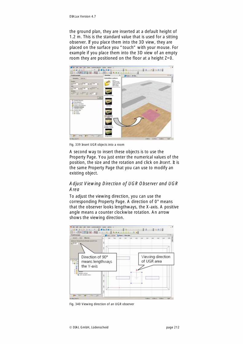
DIALux Version 4.7
DIAL GmbH, Lüdenscheid page 212
the ground plan, they are inserted at a default height of 1.2 m. This is the standard value that is used for a sitting observer. If you place them into the 3D view, they are placed on the surface you “touch” with your mouse. For example if you place them into the 3D view of an empty room they are positioned on the floor at a height Z=0.
Fig. 339 Insert UGR objects into a room
A second way to insert these objects is to use the Property Page. You just enter the numerical values of the position, the size and the rotation and click on Insert. It is the same Property Page that you can use to modify an existing object.
Adjust Viewing Direction of UGR Observer and UGR Area To adjust the viewing direction, you can use the corresponding Property Page. A direction of 0° means that the observer looks lengthways, the X-axis. A positive angle means a counter clockwise rotation. An arrow shows the viewing direction.
Fig. 340 Viewing direction of an UGR observer
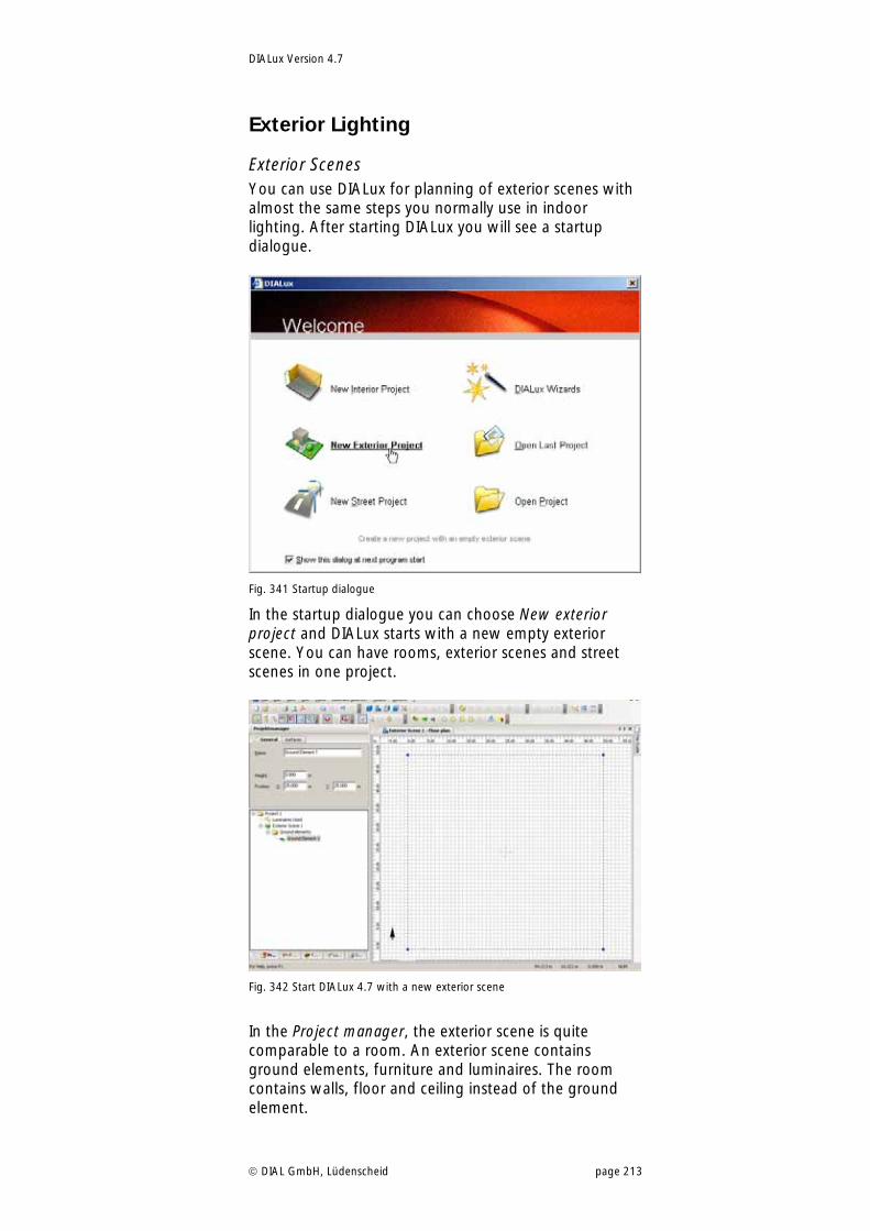
DIALux Version 4.7
DIAL GmbH, Lüdenscheid page 213
Exterior Lighting
Exterior Scenes You can use DIALux for planning of exterior scenes with almost the same steps you normally use in indoor lighting. After starting DIALux you will see a startup dialogue.
Fig. 341 Startup dialogue
In the startup dialogue you can choose New exterior project and DIALux starts with a new empty exterior scene. You can have rooms, exterior scenes and street scenes in one project.
Fig. 342 Start DIALux 4.7 with a new exterior scene
In the Project manager, the exterior scene is quite comparable to a room. An exterior scene contains ground elements, furniture and luminaires. The room contains walls, floor and ceiling instead of the ground element.
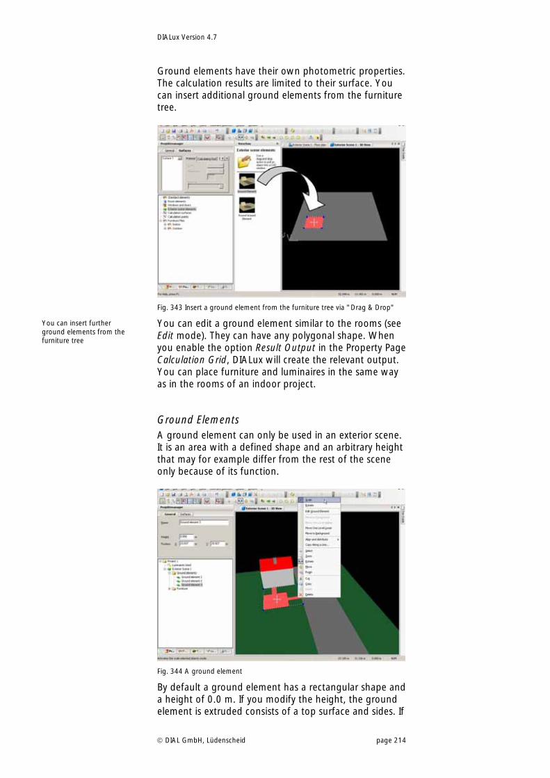
DIALux Version 4.7
DIAL GmbH, Lüdenscheid page 214
Ground elements have their own photometric properties. The calculation results are limited to their surface. You can insert additional ground elements from the furniture tree.
Fig. 343 Insert a ground element from the furniture tree via "Drag & Drop"
You can edit a ground element similar to the rooms (see Edit mode). They can have any polygonal shape. When you enable the option Result Output in the Property Page Calculation Grid, DIALux will create the relevant output. You can place furniture and luminaires in the same way as in the rooms of an indoor project.
Ground Elements A ground element can only be used in an exterior scene. It is an area with a defined shape and an arbitrary height that may for example differ from the rest of the scene only because of its function.
Fig. 344 A ground element
By default a ground element has a rectangular shape and a height of 0.0 m. If you modify the height, the ground element is extruded consists of a top surface and sides. If
You can insert further ground elements from the furniture tree
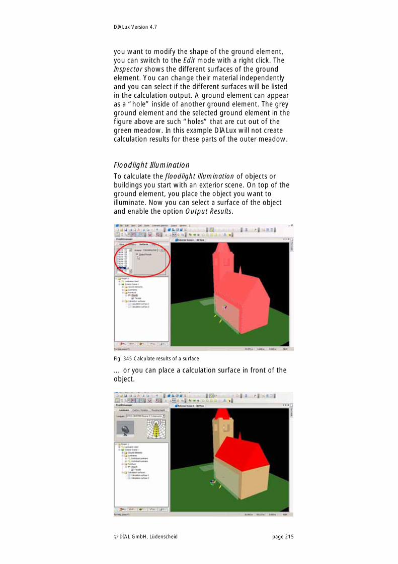
DIALux Version 4.7
DIAL GmbH, Lüdenscheid page 215
you want to modify the shape of the ground element, you can switch to the Edit mode with a right click. The Inspector shows the different surfaces of the ground element. You can change their material independently and you can select if the different surfaces will be listed in the calculation output. A ground element can appear as a “hole” inside of another ground element. The grey ground element and the selected ground element in the figure above are such “holes” that are cut out of the green meadow. In this example DIALux will not create calculation results for these parts of the outer meadow.
Floodlight Illumination To calculate the floodlight illumination of objects or buildings you start with an exterior scene. On top of the ground element, you place the object you want to illuminate. Now you can select a surface of the object and enable the option Output Results.
Fig. 345 Calculate results of a surface
… or you can place a calculation surface in front of the object.
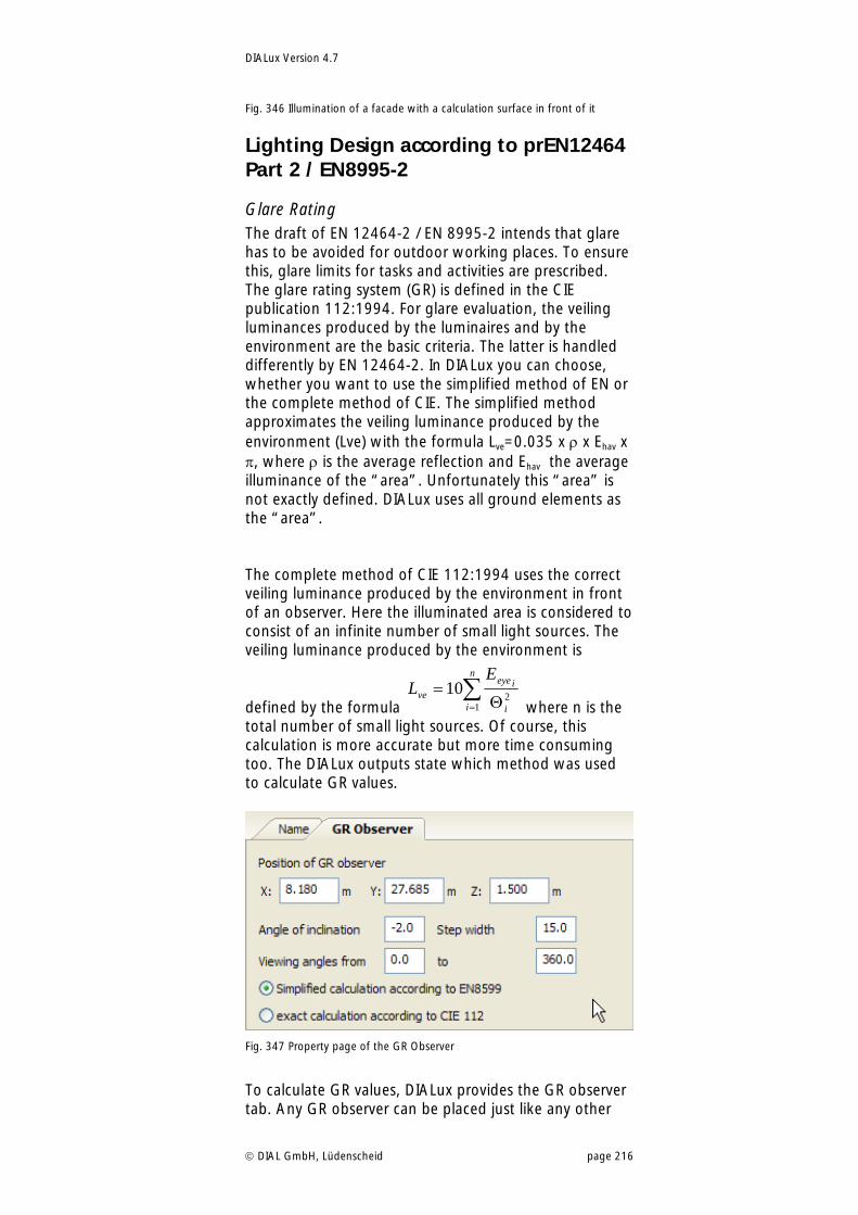
DIALux Version 4.7
DIAL GmbH, Lüdenscheid page 216
Fig. 346 Illumination of a facade with a calculation surface in front of it
Lighting Design according to prEN12464 Part 2 / EN8995-2
Glare Rating The draft of EN 12464-2 / EN 8995-2 intends that glare has to be avoided for outdoor working places. To ensure this, glare limits for tasks and activities are prescribed. The glare rating system (GR) is defined in the CIE publication 112:1994. For glare evaluation, the veiling luminances produced by the luminaires and by the environment are the basic criteria. The latter is handled differently by EN 12464-2. In DIALux you can choose, whether you want to use the simplified method of EN or the complete method of CIE. The simplified method approximates the veiling luminance produced by the environment (Lve) with the formula Lve=0.035 x x Ehav x , where is the average reflection and Ehav the average illuminance of the “area”. Unfortunately this “area” is not exactly defined. DIALux uses all ground elements as the “area”. The complete method of CIE 112:1994 uses the correct veiling luminance produced by the environment in front of an observer. Here the illuminated area is considered to consist of an infinite number of small light sources. The veiling luminance produced by the environment is
defined by the formula
n
i i
ieye
ve
EL
12
10 where n is the
total number of small light sources. Of course, this calculation is more accurate but more time consuming too. The DIALux outputs state which method was used to calculate GR values.
Fig. 347 Property page of the GR Observer
To calculate GR values, DIALux provides the GR observer tab. Any GR observer can be placed just like any other
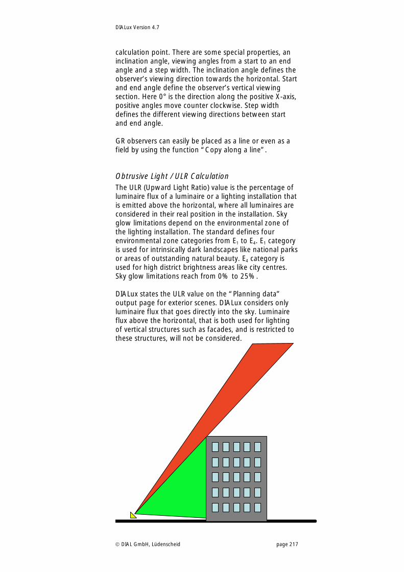
DIALux Version 4.7
DIAL GmbH, Lüdenscheid page 217
calculation point. There are some special properties, an inclination angle, viewing angles from a start to an end angle and a step width. The inclination angle defines the observer’s viewing direction towards the horizontal. Start and end angle define the observer’s vertical viewing section. Here 0° is the direction along the positive X-axis, positive angles move counter clockwise. Step width defines the different viewing directions between start and end angle. GR observers can easily be placed as a line or even as a field by using the function “Copy along a line”.
Obtrusive Light / ULR Calculation The ULR (Upward Light Ratio) value is the percentage of luminaire flux of a luminaire or a lighting installation that is emitted above the horizontal, where all luminaires are considered in their real position in the installation. Sky glow limitations depend on the environmental zone of the lighting installation. The standard defines four environmental zone categories from E1 to E4. E1 category is used for intrinsically dark landscapes like national parks or areas of outstanding natural beauty. E4 category is used for high district brightness areas like city centres. Sky glow limitations reach from 0% to 25%. DIALux states the ULR value on the “Planning data” output page for exterior scenes. DIALux considers only luminaire flux that goes directly into the sky. Luminaire flux above the horizontal, that is both used for lighting of vertical structures such as facades, and is restricted to these structures, will not be considered.
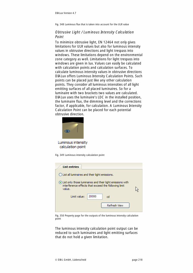
DIALux Version 4.7
DIAL GmbH, Lüdenscheid page 218
Fig. 348 Luminous flux that is taken into account for the ULR value
Obtrusive Light / Luminous Intensity Calculation Point To minimize obtrusive light, EN 12464 not only gives limitations for ULR values but also for luminous intensity values in obtrusive directions and light trespass into windows. These limitations depend on the environmental zone category as well. Limitations for light trespass into windows are given in lux. Values can easily be calculated with calculation points and calculation surfaces. To calculate luminous intensity values in obtrusive directions DIALux offers Luminous Intensity Calculation Points. Such points can be placed just like any other calculation points. They consider all luminous intensities of all light emitting surfaces of all placed luminaires. So for a luminaire with two brackets two values are calculated. DIALux uses the luminaire’s LDC in the installed position, the luminaire flux, the dimming level and the corrections factor, if applicable, for calculation. A Luminous Intensity Calculation Point can be placed for each potential obtrusive direction.
Fig. 349 Luminous intensity calculation point
Fig. 350 Property page for the outputs of the luminous intensity calculation point
The luminous intensity calculation point output can be reduced to such luminaires and light emitting surfaces that do not hold a given limitation.
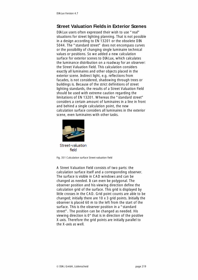
DIALux Version 4.7
DIAL GmbH, Lüdenscheid page 219
Street Valuation Fields in Exterior Scenes DIALux users often expressed their wish to use “real” situations for street lighting planning. That is not possible in a design according to EN 13201 or the obsolete DIN 5044. The “standard street” does not encompass curves or the possibility of changing single luminaire technical values or positions. So we added a new calculation surface for exterior scenes to DIALux, which calculates the luminance distribution on a roadway for an observer: the Street Valuation Field. This calculation considers exactly all luminaires and other objects placed in the exterior scene. Indirect light, e.g. reflections from facades, is not considered, shadowing through trees or buildings is. Because of the strict definitions of street lighting standards, the results of a Street Valuation Field should be used with extreme caution regarding the limitations of EN 13201. Whereas the “standard street” considers a certain amount of luminaires in a line in front and behind a single calculation point, the new calculation surface considers all luminaires in the exterior scene, even luminaires with other tasks.
Fig. 351 Calculation surface Street-valuation field
A Street Valuation Field consists of two parts: the calculation surface itself and a corresponding observer. The surface is visible in CAD windows and can be changed as needed. It can even be polygonal. The observer position and his viewing direction define the calculation grid of the surface. This grid is displayed by little crosses in the CAD. Grid point counts are able to be changed; initially there are 10 x 3 grid points. Initially the observer is placed 60 m to the left from the start of the surface. This is the observer position in a “standard street”. The position can be changed as needed. His viewing direction is 0° that is in direction of the positive X-axis. Therefore the grid points are initially parallel to the X-axis as well.
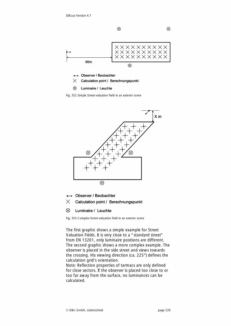
DIALux Version 4.7
DIAL GmbH, Lüdenscheid page 220
60m
Observer / Beobachter
Calculation point / Berechnungspunkt
Luminaire / Leuchte
60m
Observer / Beobachter
Calculation point / Berechnungspunkt
Luminaire / Leuchte Fig. 352 Simple Street-valuation field in an exterior scene
X m
Observer / Beobachter
Calculation point / Berechnungspunkt
Luminaire / Leuchte
X m
Observer / Beobachter
Calculation point / Berechnungspunkt
Luminaire / Leuchte Fig. 353 Complex Street-valuation field in an exterior scene
The first graphic shows a simple example for Street Valuation Fields. It is very close to a “standard street” from EN 13201, only luminaire positions are different. The second graphic shows a more complex example. The observer is placed in the side street and views towards the crossing. His viewing direction (ca. 225°) defines the calculation grid’s orientation. Note: Reflection properties of tarmacs are only defined for close sectors. If the observer is placed too close to or too far away from the surface, no luminances can be calculated.
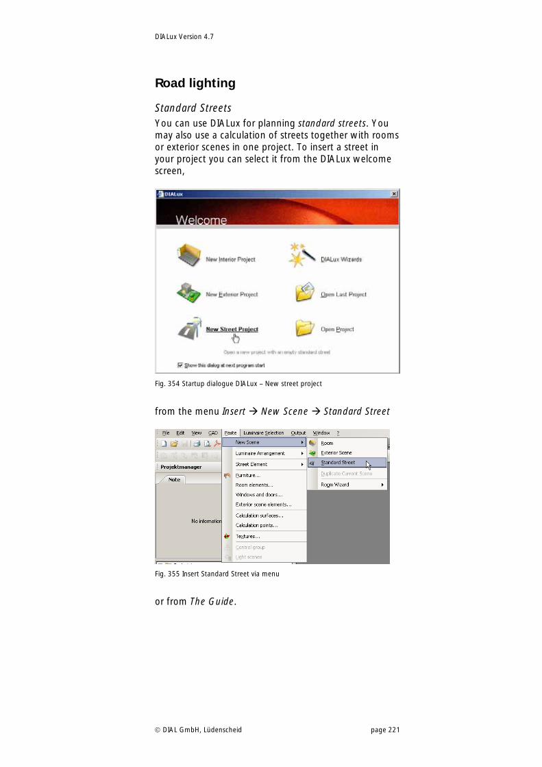
DIALux Version 4.7
DIAL GmbH, Lüdenscheid page 221
Road lighting
Standard Streets You can use DIALux for planning standard streets. You may also use a calculation of streets together with rooms or exterior scenes in one project. To insert a street in your project you can select it from the DIALux welcome screen,
Fig. 354 Startup dialogue DIALux – New street project
from the menu Insert New Scene Standard Street
Fig. 355 Insert Standard Street via menu
or from The Guide.
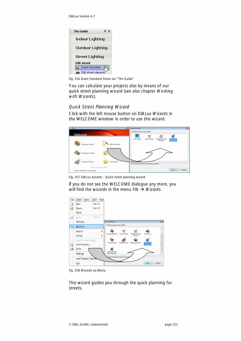
DIALux Version 4.7
DIAL GmbH, Lüdenscheid page 222
Fig. 356 Insert Standard Street via “The Guide”
You can calculate your projects also by means of our quick street planning wizard (see also chapter Working with Wizards).
Quick Street Planning Wizard Click with the left mouse button on DIALux Wizards in the WELCOME window in order to use this wizard.
Fig. 357 DIALux wizards – Quick street-planning wizard
If you do not see the WELCOME dialogue any more, you will find the wizards in the menu File Wizards.
Fig. 358 Wizards via Menu
This wizard guides you through the quick planning for streets.
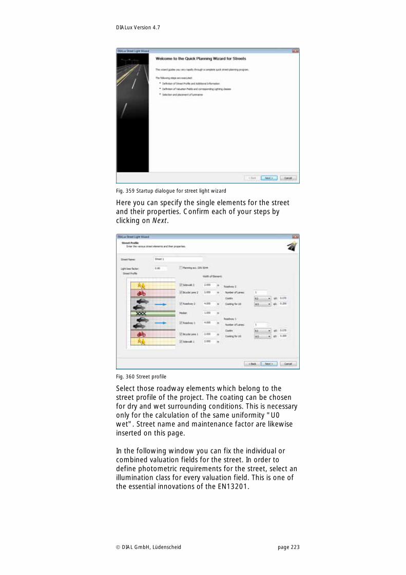
DIALux Version 4.7
DIAL GmbH, Lüdenscheid page 223
Fig. 359 Startup dialogue for street light wizard
Here you can specify the single elements for the street and their properties. Confirm each of your steps by clicking on Next.
Fig. 360 Street profile
Select those roadway elements which belong to the street profile of the project. The coating can be chosen for dry and wet surrounding conditions. This is necessary only for the calculation of the same uniformity "U0 wet". Street name and maintenance factor are likewise inserted on this page. In the following window you can fix the individual or combined valuation fields for the street. In order to define photometric requirements for the street, select an illumination class for every valuation field. This is one of the essential innovations of the EN13201.
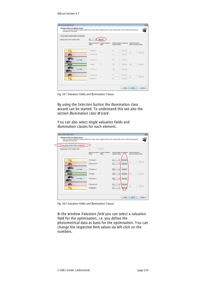
DIALux Version 4.7
DIAL GmbH, Lüdenscheid page 224
Fig. 361 Valuation Fields and Illumination Classes
By using the Selection button the illumination class wizard can be started. To understand this see also the section Illumination class Wizard. You can also select single valuation fields and illumination classes for each element.
Fig. 362 Valuation Fields and Illumination Classes
In the window Valuation field you can select a valuation field for the optimisation, i.e. you define the photometrical data as basis for the optimisation. You can change the respective limit values via left-click on the numbers.
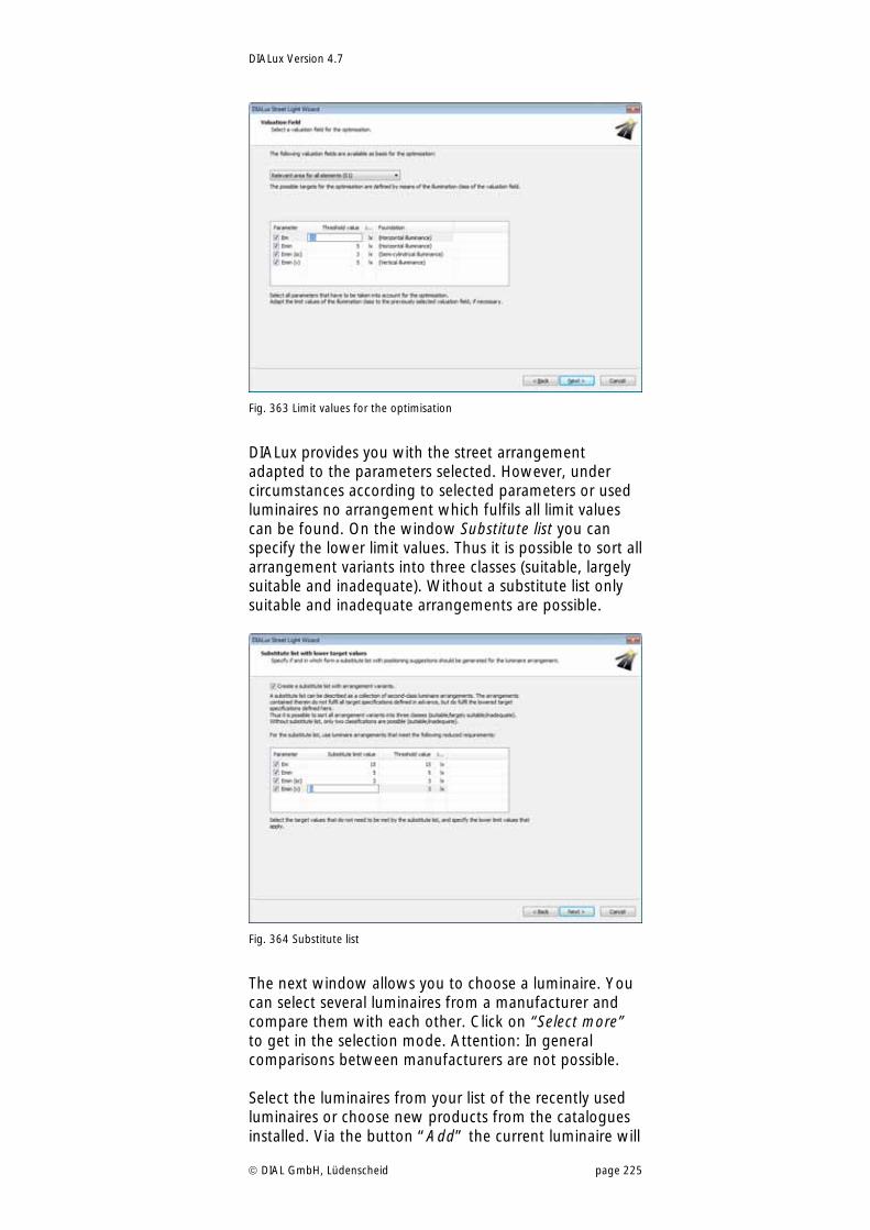
DIALux Version 4.7
DIAL GmbH, Lüdenscheid page 225
Fig. 363 Limit values for the optimisation
DIALux provides you with the street arrangement adapted to the parameters selected. However, under circumstances according to selected parameters or used luminaires no arrangement which fulfils all limit values can be found. On the window Substitute list you can specify the lower limit values. Thus it is possible to sort all arrangement variants into three classes (suitable, largely suitable and inadequate). Without a substitute list only suitable and inadequate arrangements are possible.
Fig. 364 Substitute list
The next window allows you to choose a luminaire. You can select several luminaires from a manufacturer and compare them with each other. Click on “Select more” to get in the selection mode. Attention: In general comparisons between manufacturers are not possible. Select the luminaires from your list of the recently used luminaires or choose new products from the catalogues installed. Via the button “Add” the current luminaire will
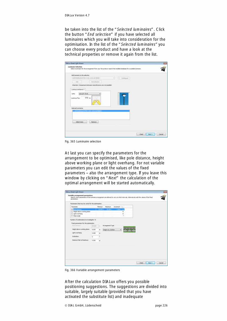
DIALux Version 4.7
DIAL GmbH, Lüdenscheid page 226
be taken into the list of the “Selected luminaires”. Click the button “End selection” if you have selected all luminaires which you will take into consideration for the optimisation. In the list of the “Selected luminaires” you can choose every product and have a look at the technical properties or remove it again from the list.
Fig. 365 Luminaire selection
At last you can specify the parameters for the arrangement to be optimised, like pole distance, height above working plane or light overhang. For not variable parameters you can edit the values of the fixed parameters – also the arrangement type. If you leave this window by clicking on “Next” the calculation of the optimal arrangement will be started automatically.
Fig. 366 Variable arrangement parameters
After the calculation DIALux offers you possible positioning suggestions. The suggestions are divided into suitable, largely suitable (provided that you have activated the substitute list) and inadequate
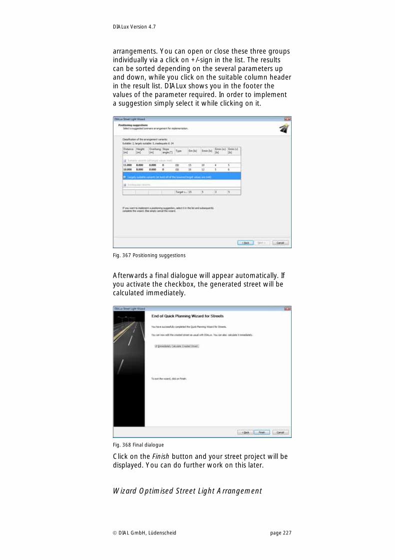
DIALux Version 4.7
DIAL GmbH, Lüdenscheid page 227
arrangements. You can open or close these three groups individually via a click on +/-sign in the list. The results can be sorted depending on the several parameters up and down, while you click on the suitable column header in the result list. DIALux shows you in the footer the values of the parameter required. In order to implement a suggestion simply select it while clicking on it.
Fig. 367 Positioning suggestions
Afterwards a final dialogue will appear automatically. If you activate the checkbox, the generated street will be calculated immediately.
Fig. 368 Final dialogue
Click on the Finish button and your street project will be displayed. You can do further work on this later.
Wizard Optimised Street Light Arrangement
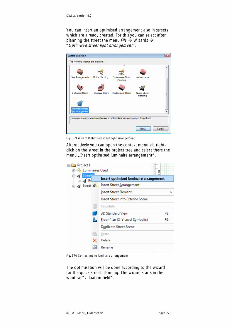
DIALux Version 4.7
DIAL GmbH, Lüdenscheid page 228
You can insert an optimised arrangement also in streets which are already created. For this you can select after planning the street the menu File Wizards “Optimised street light arrangement”.
Fig. 369 Wizard Optimised street light arrangement
Alternatively you can open the context menu via right-click on the street in the project tree and select there the menu „Insert optimised luminaire arrangement“.
Fig. 370 Context menu luminaire arrangement
The optimisation will be done according to the wizard for the quick street planning. The wizard starts in the window “valuation field”.
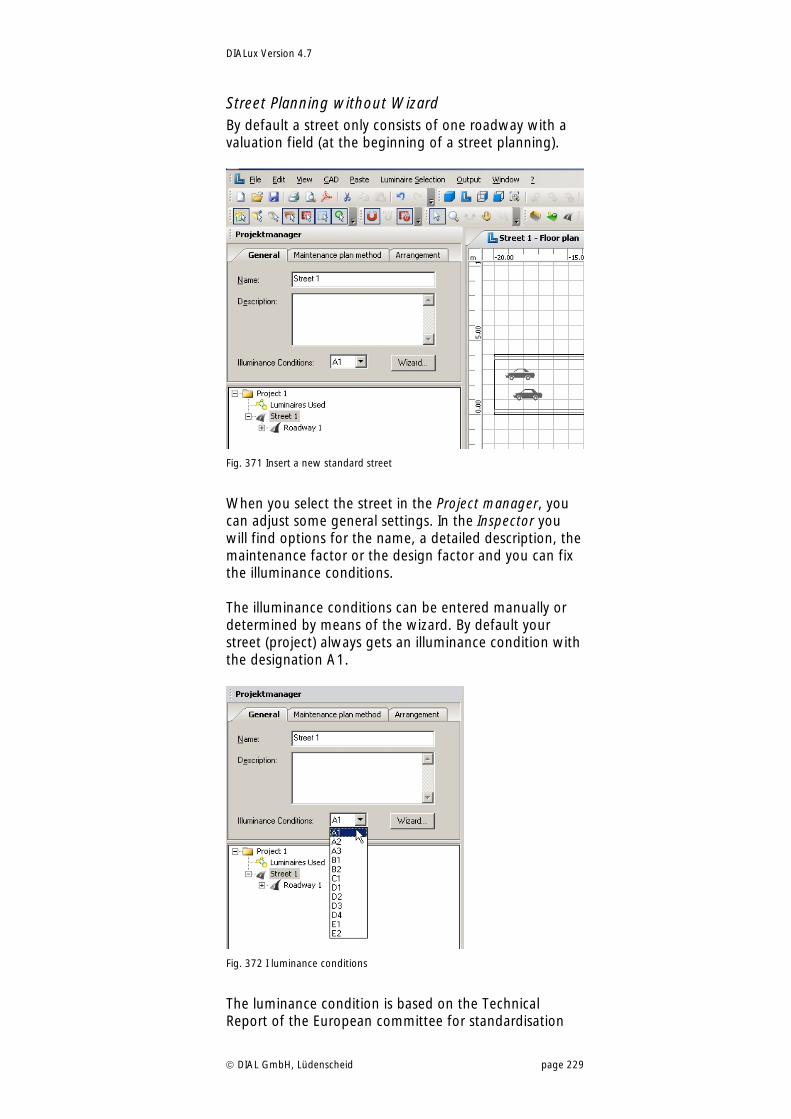
DIALux Version 4.7
DIAL GmbH, Lüdenscheid page 229
Street Planning without Wizard By default a street only consists of one roadway with a valuation field (at the beginning of a street planning).
Fig. 371 Insert a new standard street
When you select the street in the Project manager, you can adjust some general settings. In the Inspector you will find options for the name, a detailed description, the maintenance factor or the design factor and you can fix the illuminance conditions. The illuminance conditions can be entered manually or determined by means of the wizard. By default your street (project) always gets an illuminance condition with the designation A1.
Fig. 372 I luminance conditions
The luminance condition is based on the Technical Report of the European committee for standardisation
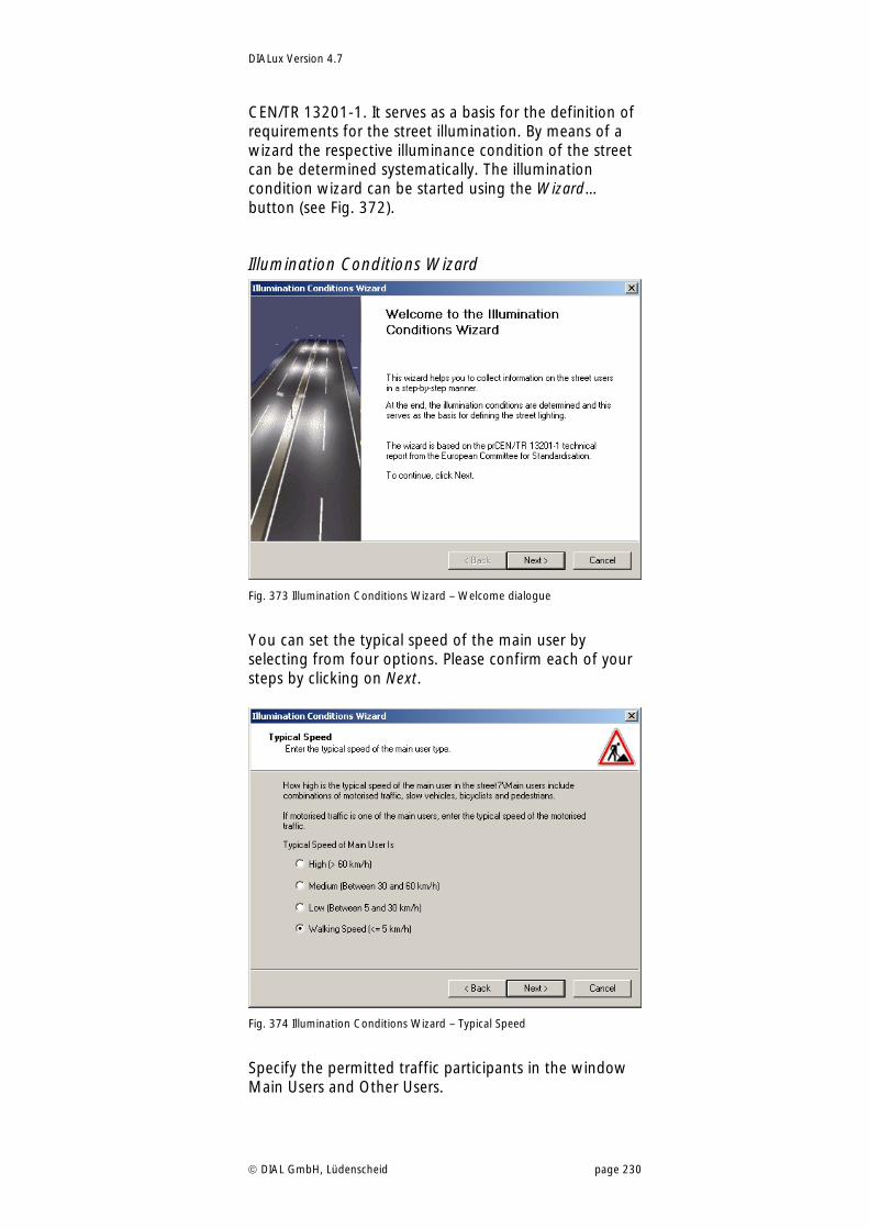
DIALux Version 4.7
DIAL GmbH, Lüdenscheid page 230
CEN/TR 13201-1. It serves as a basis for the definition of requirements for the street illumination. By means of a wizard the respective illuminance condition of the street can be determined systematically. The illumination condition wizard can be started using the Wizard… button (see Fig. 372).
Illumination Conditions Wizard
Fig. 373 Illumination Conditions Wizard – Welcome dialogue
You can set the typical speed of the main user by selecting from four options. Please confirm each of your steps by clicking on Next.
Fig. 374 Illumination Conditions Wizard – Typical Speed
Specify the permitted traffic participants in the window Main Users and Other Users.
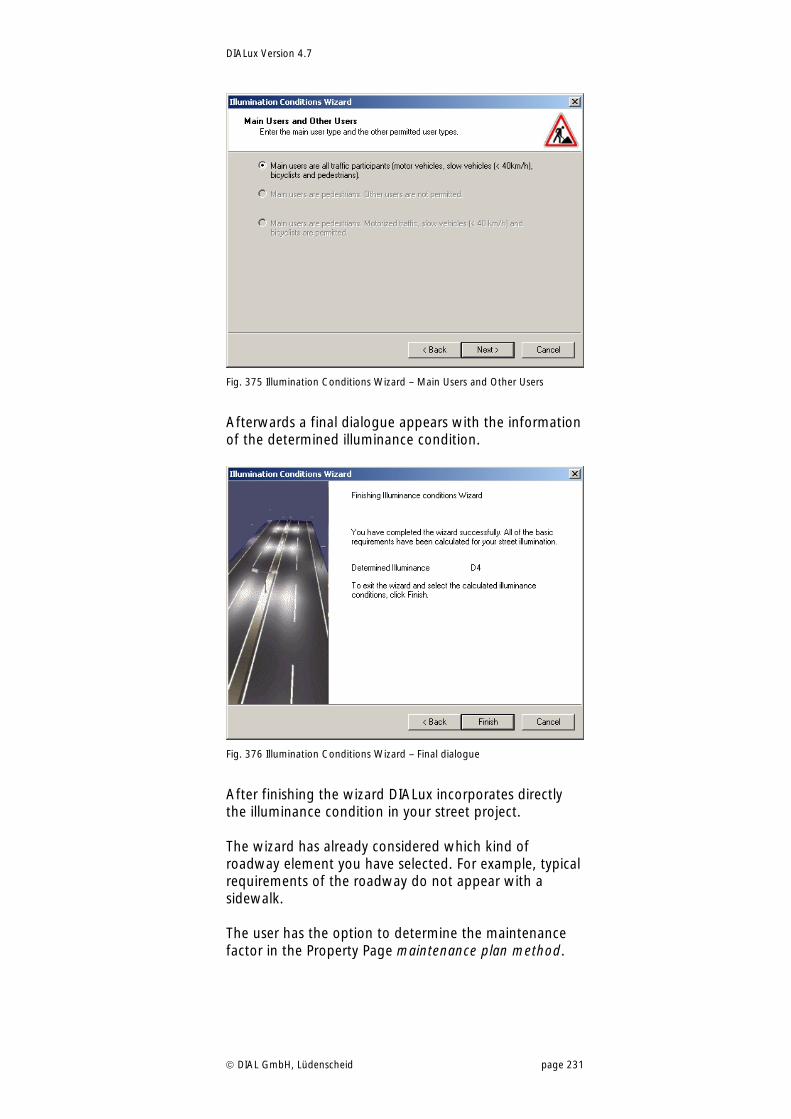
DIALux Version 4.7
DIAL GmbH, Lüdenscheid page 231
Fig. 375 Illumination Conditions Wizard – Main Users and Other Users
Afterwards a final dialogue appears with the information of the determined illuminance condition.
Fig. 376 Illumination Conditions Wizard – Final dialogue
After finishing the wizard DIALux incorporates directly the illuminance condition in your street project. The wizard has already considered which kind of roadway element you have selected. For example, typical requirements of the roadway do not appear with a sidewalk. The user has the option to determine the maintenance factor in the Property Page maintenance plan method.
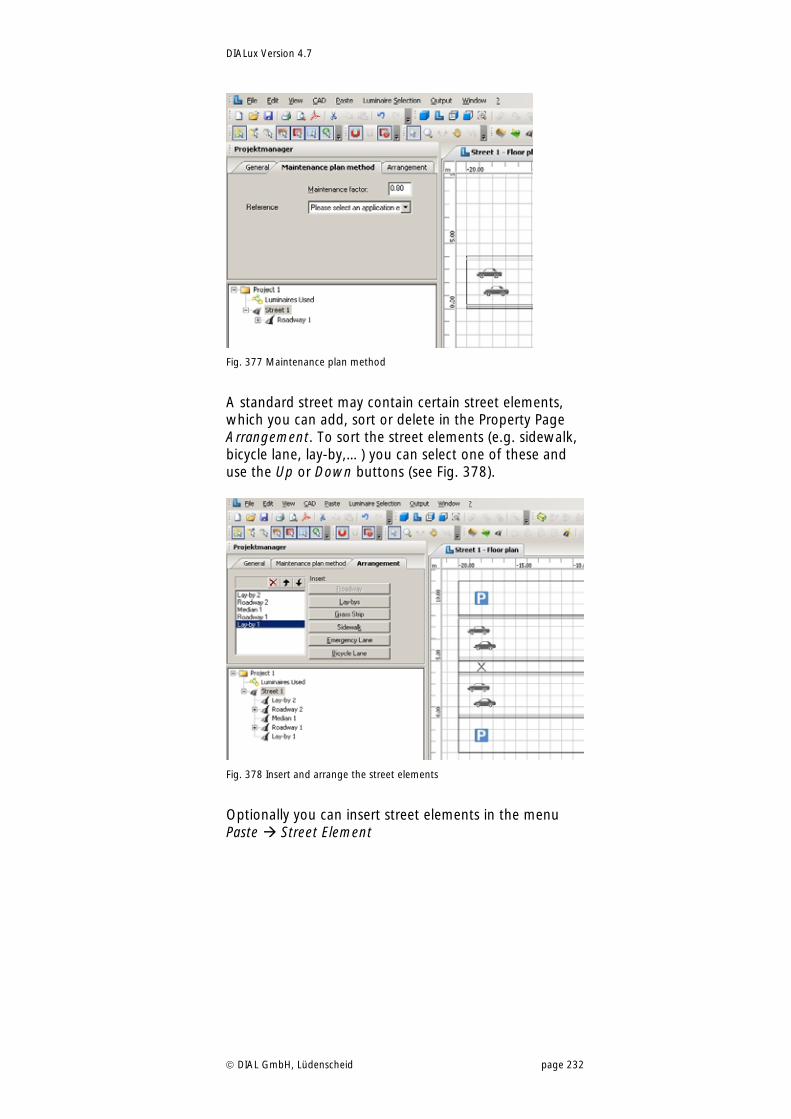
DIALux Version 4.7
DIAL GmbH, Lüdenscheid page 232
Fig. 377 Maintenance plan method
A standard street may contain certain street elements, which you can add, sort or delete in the Property Page Arrangement. To sort the street elements (e.g. sidewalk, bicycle lane, lay-by,…) you can select one of these and use the Up or Down buttons (see Fig. 378).
Fig. 378 Insert and arrange the street elements
Optionally you can insert street elements in the menu Paste Street Element
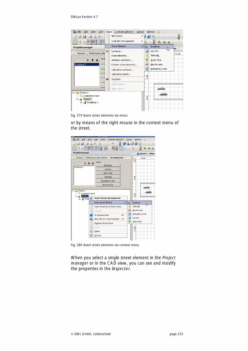
DIALux Version 4.7
DIAL GmbH, Lüdenscheid page 233
Fig. 379 Insert street elements via menu
or by means of the right mouse in the context menu of the street.
Fig. 380 Insert street elements via context menu
When you select a single street element in the Project manager or in the CAD view, you can see and modify the properties in the Inspector.
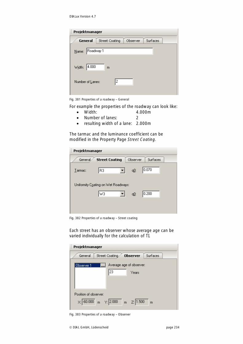
DIALux Version 4.7
DIAL GmbH, Lüdenscheid page 234
Fig. 381 Properties of a roadway – General
For example the properties of the roadway can look like: Width: 4.000m Number of lanes: 2 resulting width of a lane: 2.000m
The tarmac and the luminance coefficient can be modified in the Property Page Street Coating.
Fig. 382 Properties of a roadway – Street coating
Each street has an observer whose average age can be varied individually for the calculation of TI.
Fig. 383 Properties of a roadway – Observer
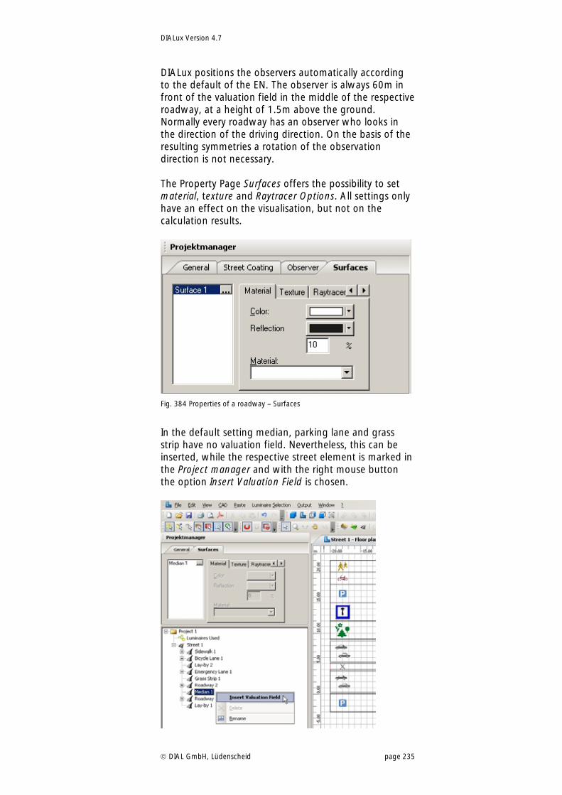
DIALux Version 4.7
DIAL GmbH, Lüdenscheid page 235
DIALux positions the observers automatically according to the default of the EN. The observer is always 60m in front of the valuation field in the middle of the respective roadway, at a height of 1.5m above the ground. Normally every roadway has an observer who looks in the direction of the driving direction. On the basis of the resulting symmetries a rotation of the observation direction is not necessary. The Property Page Surfaces offers the possibility to set material, texture and Raytracer Options. All settings only have an effect on the visualisation, but not on the calculation results.
Fig. 384 Properties of a roadway – Surfaces
In the default setting median, parking lane and grass strip have no valuation field. Nevertheless, this can be inserted, while the respective street element is marked in the Project manager and with the right mouse button the option Insert Valuation Field is chosen.
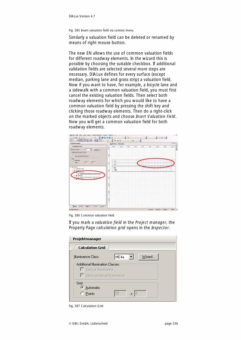
DIALux Version 4.7
DIAL GmbH, Lüdenscheid page 236
Fig. 385 Insert valuation field via context menu
Similarly a valuation field can be deleted or renamed by means of right mouse button. The new EN allows the use of common valuation fields for different roadway elements. In the wizard this is possible by choosing the suitable checkbox. If additional validation fields are selected several more steps are necessary. DIALux defines for every surface (except median, parking lane and grass strip) a valuation field. Now if you want to have, for example, a bicycle lane and a sidewalk with a common valuation field, you must first cancel the existing valuation fields. Then select both roadway elements for which you would like to have a common valuation field by pressing the shift key and clicking those roadway elements. Then do a right-click on the marked objects and choose Insert Valuation Field. Now you will get a common valuation field for both roadway elements.
Fig. 386 Common valuation field
If you mark a valuation field in the Project manager, the Property Page calculation grid opens in the Inspector.
Fig. 387 Calculation Grid
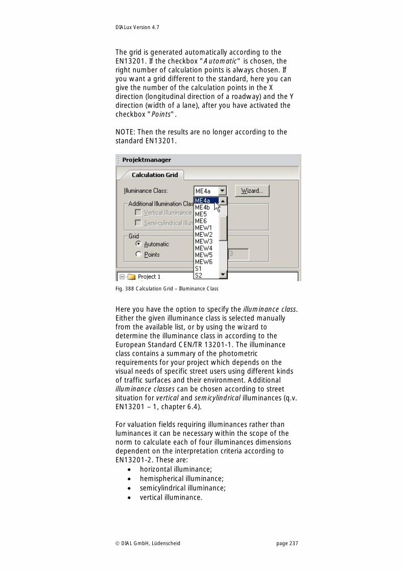
DIALux Version 4.7
DIAL GmbH, Lüdenscheid page 237
The grid is generated automatically according to the EN13201. If the checkbox "Automatic" is chosen, the right number of calculation points is always chosen. If you want a grid different to the standard, here you can give the number of the calculation points in the X direction (longitudinal direction of a roadway) and the Y direction (width of a lane), after you have activated the checkbox "Points". NOTE: Then the results are no longer according to the standard EN13201.
Fig. 388 Calculation Grid – Illuminance Class
Here you have the option to specify the illuminance class. Either the given illuminance class is selected manually from the available list, or by using the wizard to determine the illuminance class in according to the European Standard CEN/TR 13201-1. The illuminance class contains a summary of the photometric requirements for your project which depends on the visual needs of specific street users using different kinds of traffic surfaces and their environment. Additional illuminance classes can be chosen according to street situation for vertical and semicylindrical illuminances (q.v. EN13201 – 1, chapter 6.4). For valuation fields requiring illuminances rather than luminances it can be necessary within the scope of the norm to calculate each of four illuminances dimensions dependent on the interpretation criteria according to EN13201-2. These are:
horizontal illuminance; hemispherical illuminance; semicylindrical illuminance; vertical illuminance.
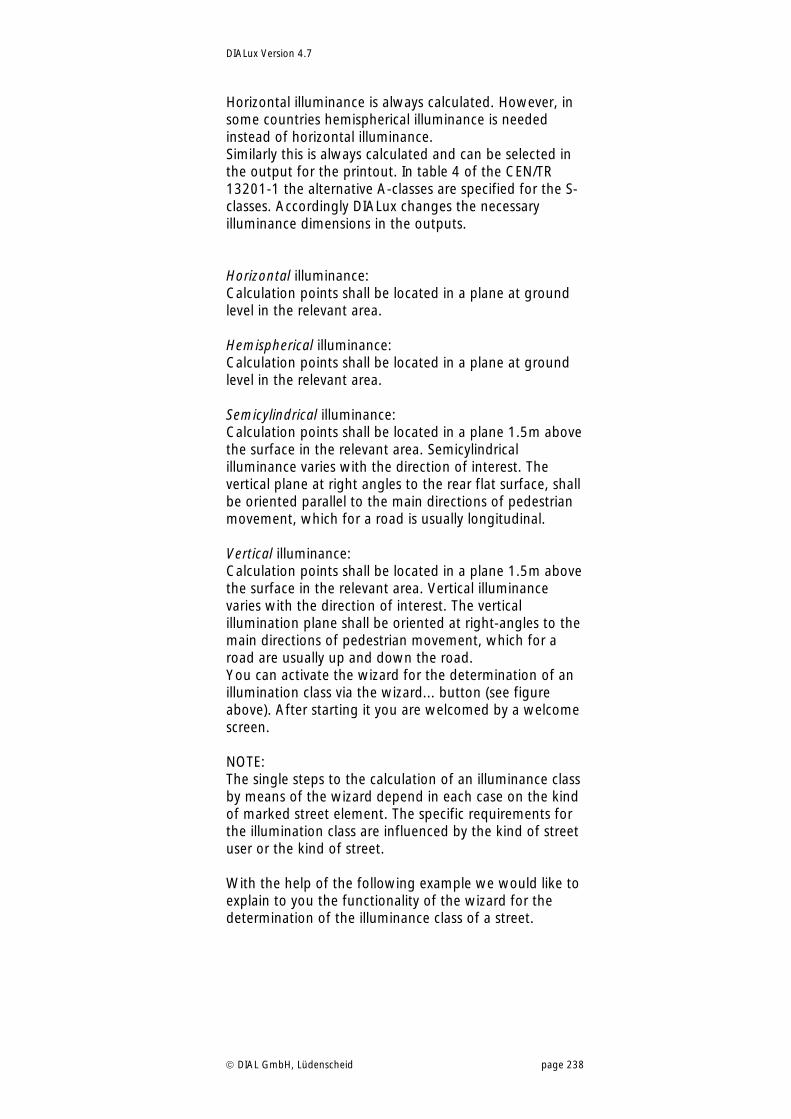
DIALux Version 4.7
DIAL GmbH, Lüdenscheid page 238
Horizontal illuminance is always calculated. However, in some countries hemispherical illuminance is needed instead of horizontal illuminance. Similarly this is always calculated and can be selected in the output for the printout. In table 4 of the CEN/TR 13201-1 the alternative A-classes are specified for the S-classes. Accordingly DIALux changes the necessary illuminance dimensions in the outputs. Horizontal illuminance: Calculation points shall be located in a plane at ground level in the relevant area. Hemispherical illuminance: Calculation points shall be located in a plane at ground level in the relevant area. Semicylindrical illuminance: Calculation points shall be located in a plane 1.5m above the surface in the relevant area. Semicylindrical illuminance varies with the direction of interest. The vertical plane at right angles to the rear flat surface, shall be oriented parallel to the main directions of pedestrian movement, which for a road is usually longitudinal. Vertical illuminance: Calculation points shall be located in a plane 1.5m above the surface in the relevant area. Vertical illuminance varies with the direction of interest. The vertical illumination plane shall be oriented at right-angles to the main directions of pedestrian movement, which for a road are usually up and down the road. You can activate the wizard for the determination of an illumination class via the wizard... button (see figure above). After starting it you are welcomed by a welcome screen. NOTE: The single steps to the calculation of an illuminance class by means of the wizard depend in each case on the kind of marked street element. The specific requirements for the illumination class are influenced by the kind of street user or the kind of street. With the help of the following example we would like to explain to you the functionality of the wizard for the determination of the illuminance class of a street.
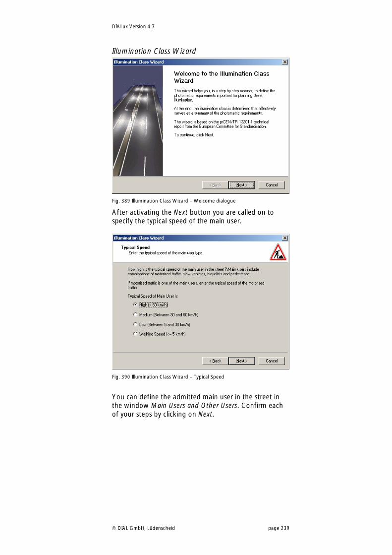
DIALux Version 4.7
DIAL GmbH, Lüdenscheid page 239
Illumination Class Wizard
Fig. 389 Illumination Class Wizard – Welcome dialogue
After activating the Next button you are called on to specify the typical speed of the main user.
Fig. 390 Illumination Class Wizard – Typical Speed
You can define the admitted main user in the street in the window Main Users and Other Users. Confirm each of your steps by clicking on Next.
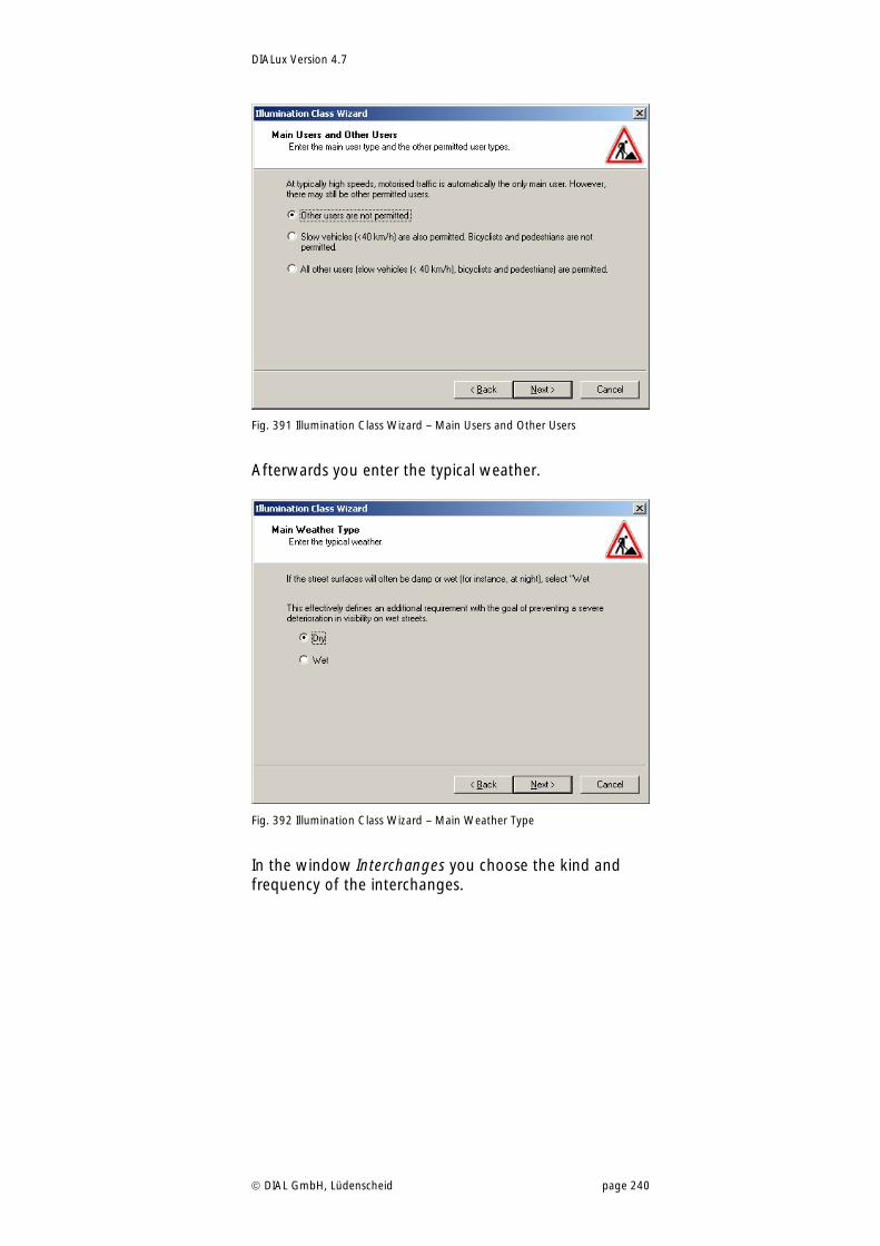
DIALux Version 4.7
DIAL GmbH, Lüdenscheid page 240
Fig. 391 Illumination Class Wizard – Main Users and Other Users
Afterwards you enter the typical weather.
Fig. 392 Illumination Class Wizard – Main Weather Type
In the window Interchanges you choose the kind and frequency of the interchanges.
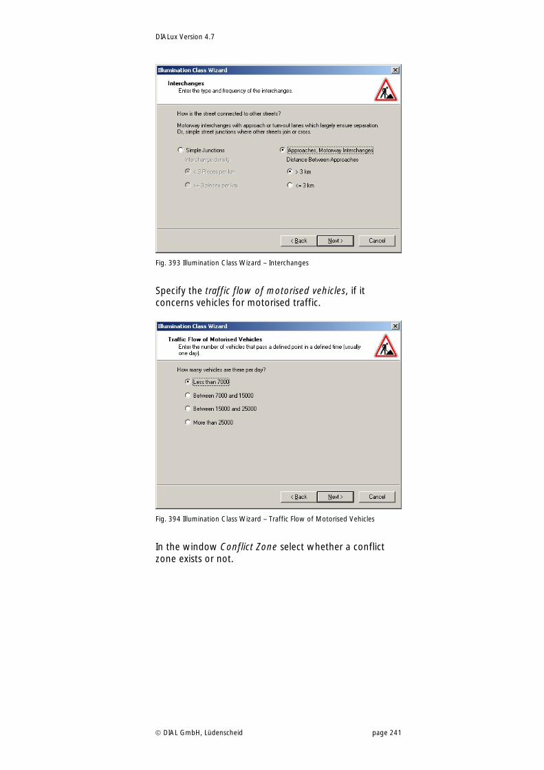
DIALux Version 4.7
DIAL GmbH, Lüdenscheid page 241
Fig. 393 Illumination Class Wizard – Interchanges
Specify the traffic flow of motorised vehicles, if it concerns vehicles for motorised traffic.
Fig. 394 Illumination Class Wizard – Traffic Flow of Motorised Vehicles
In the window Conflict Zone select whether a conflict zone exists or not.
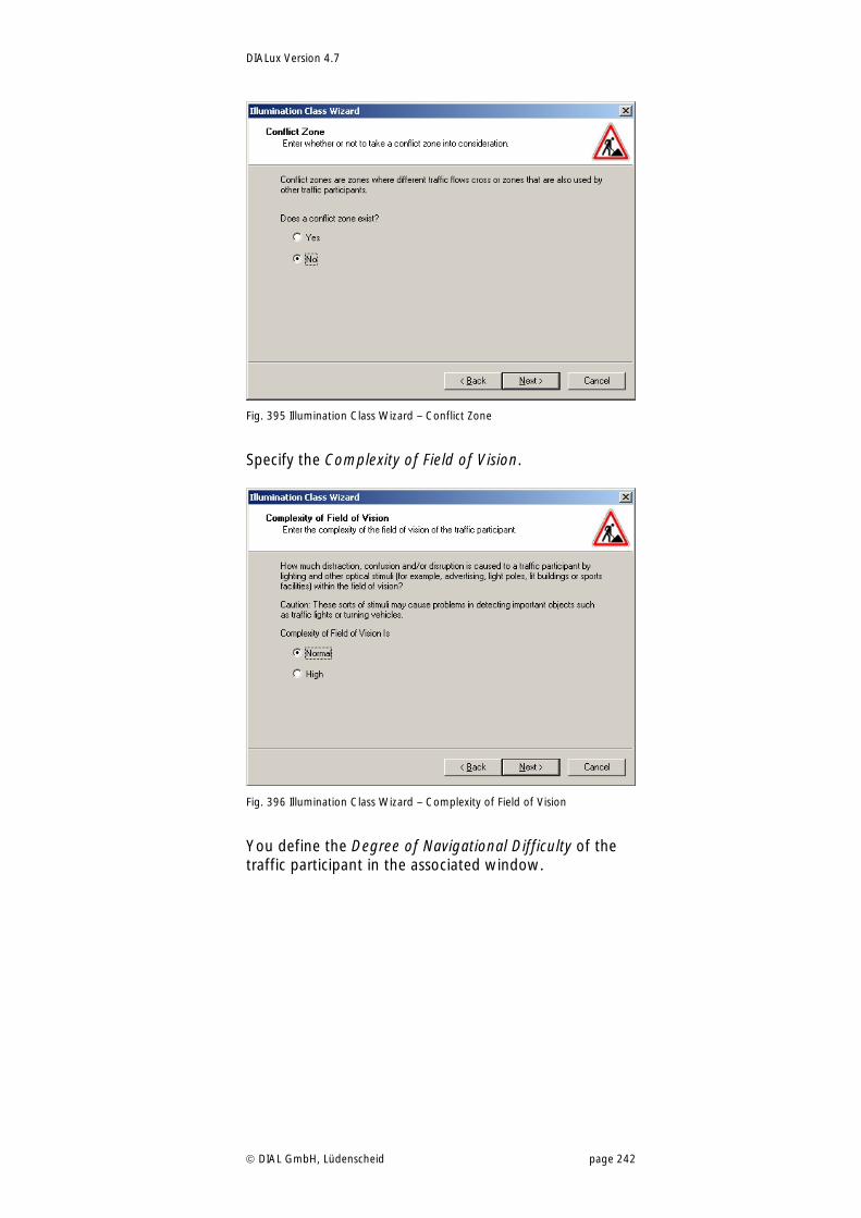
DIALux Version 4.7
DIAL GmbH, Lüdenscheid page 242
Fig. 395 Illumination Class Wizard – Conflict Zone
Specify the Complexity of Field of Vision.
Fig. 396 Illumination Class Wizard – Complexity of Field of Vision
You define the Degree of Navigational Difficulty of the traffic participant in the associated window.
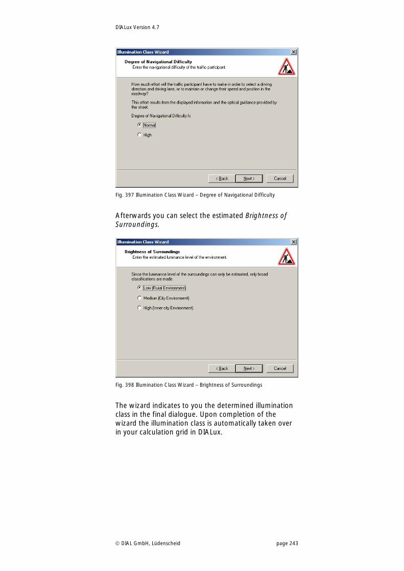
DIALux Version 4.7
DIAL GmbH, Lüdenscheid page 243
Fig. 397 Illumination Class Wizard – Degree of Navigational Difficulty
Afterwards you can select the estimated Brightness of Surroundings.
Fig. 398 Illumination Class Wizard – Brightness of Surroundings
The wizard indicates to you the determined illumination class in the final dialogue. Upon completion of the wizard the illumination class is automatically taken over in your calculation grid in DIALux.
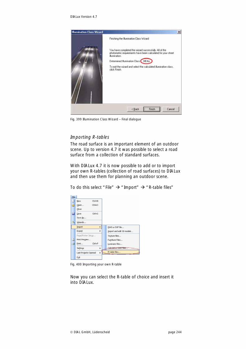
DIALux Version 4.7
DIAL GmbH, Lüdenscheid page 244
Fig. 399 Illumination Class Wizard – Final dialogue
Importing R-tables The road surface is an important element of an outdoor scene. Up to version 4.7 it was possible to select a road surface from a collection of standard surfaces. With DIALux 4.7 it is now possible to add or to import your own R-tables (collection of road surfaces) to DIALux and then use them for planning an outdoor scene. To do this select “File” “Import” “R-table files”
Fig. 400 Importing your own R-table
Now you can select the R-table of choice and insert it into DIALux.
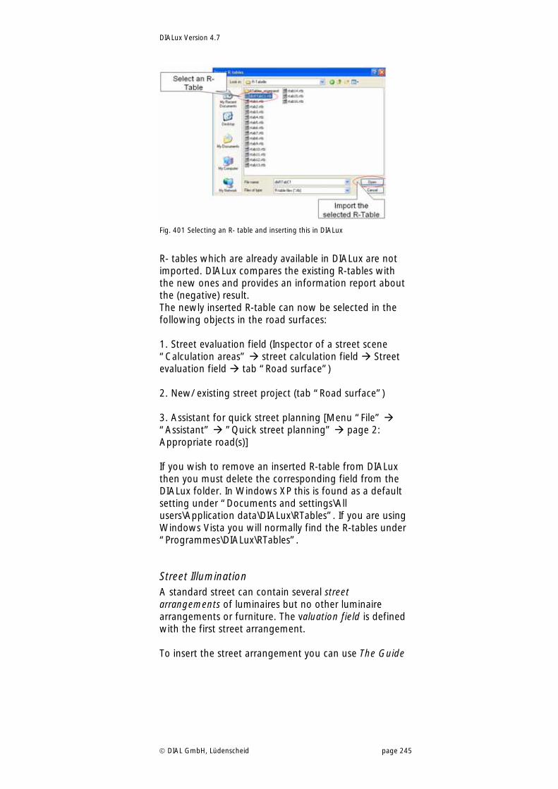
DIALux Version 4.7
DIAL GmbH, Lüdenscheid page 245
Fig. 401 Selecting an R- table and inserting this in DIALux
R- tables which are already available in DIALux are not imported. DIALux compares the existing R-tables with the new ones and provides an information report about the (negative) result. The newly inserted R-table can now be selected in the following objects in the road surfaces: 1. Street evaluation field (Inspector of a street scene “Calculation areas” street calculation field Street evaluation field tab “Road surface”) 2. New/ existing street project (tab “Road surface”) 3. Assistant for quick street planning [Menu “File” “Assistant” ”Quick street planning” page 2: Appropriate road(s)] If you wish to remove an inserted R-table from DIALux then you must delete the corresponding field from the DIALux folder. In Windows XP this is found as a default setting under “Documents and settings\All users\Application data\DIALux\RTables”. If you are using Windows Vista you will normally find the R-tables under “Programmes\DIALux\RTables”.
Street Illumination A standard street can contain several street arrangements of luminaires but no other luminaire arrangements or furniture. The valuation field is defined with the first street arrangement. To insert the street arrangement you can use The Guide
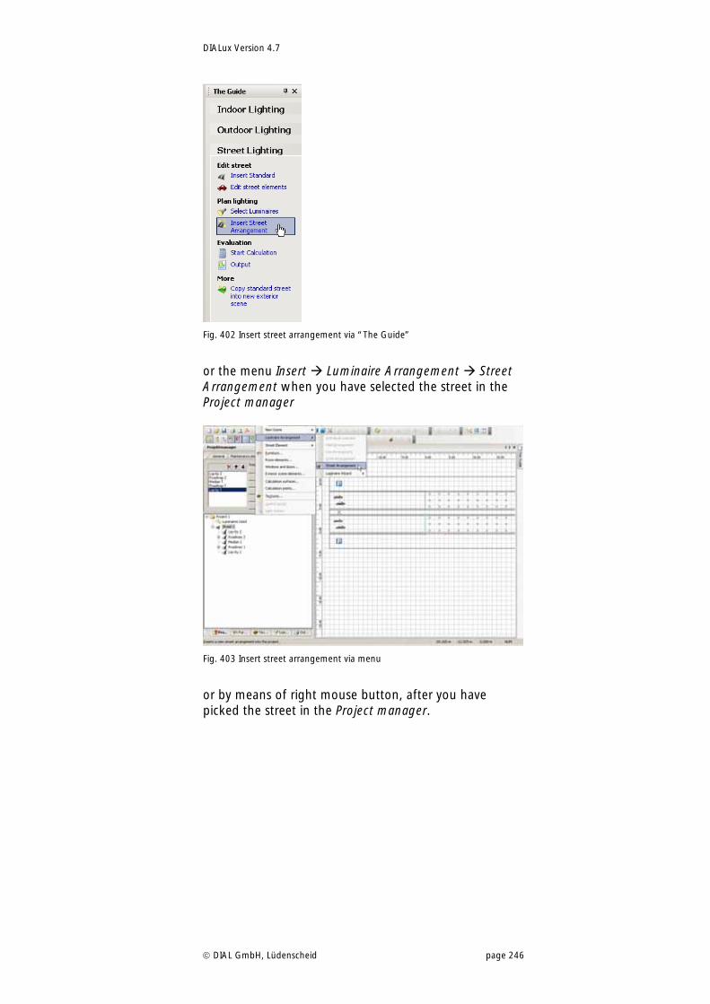
DIALux Version 4.7
DIAL GmbH, Lüdenscheid page 246
Fig. 402 Insert street arrangement via “The Guide”
or the menu Insert Luminaire Arrangement Street Arrangement when you have selected the street in the Project manager
Fig. 403 Insert street arrangement via menu
or by means of right mouse button, after you have picked the street in the Project manager.
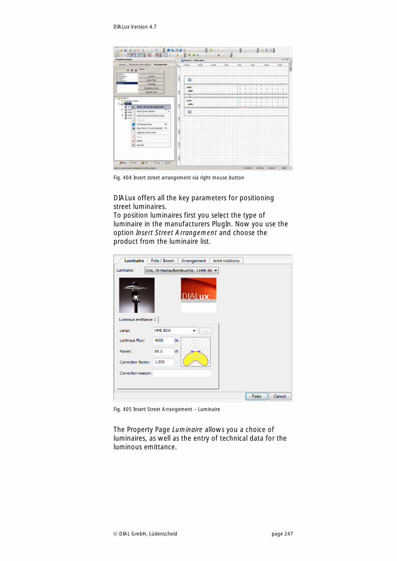
DIALux Version 4.7
DIAL GmbH, Lüdenscheid page 247
Fig. 404 Insert street arrangement via right mouse button
DIALux offers all the key parameters for positioning street luminaires. To position luminaires first you select the type of luminaire in the manufacturers PlugIn. Now you use the option Insert Street Arrangement and choose the product from the luminaire list.
Fig. 405 Insert Street Arrangement – Luminaire
The Property Page Luminaire allows you a choice of luminaires, as well as the entry of technical data for the luminous emittance.
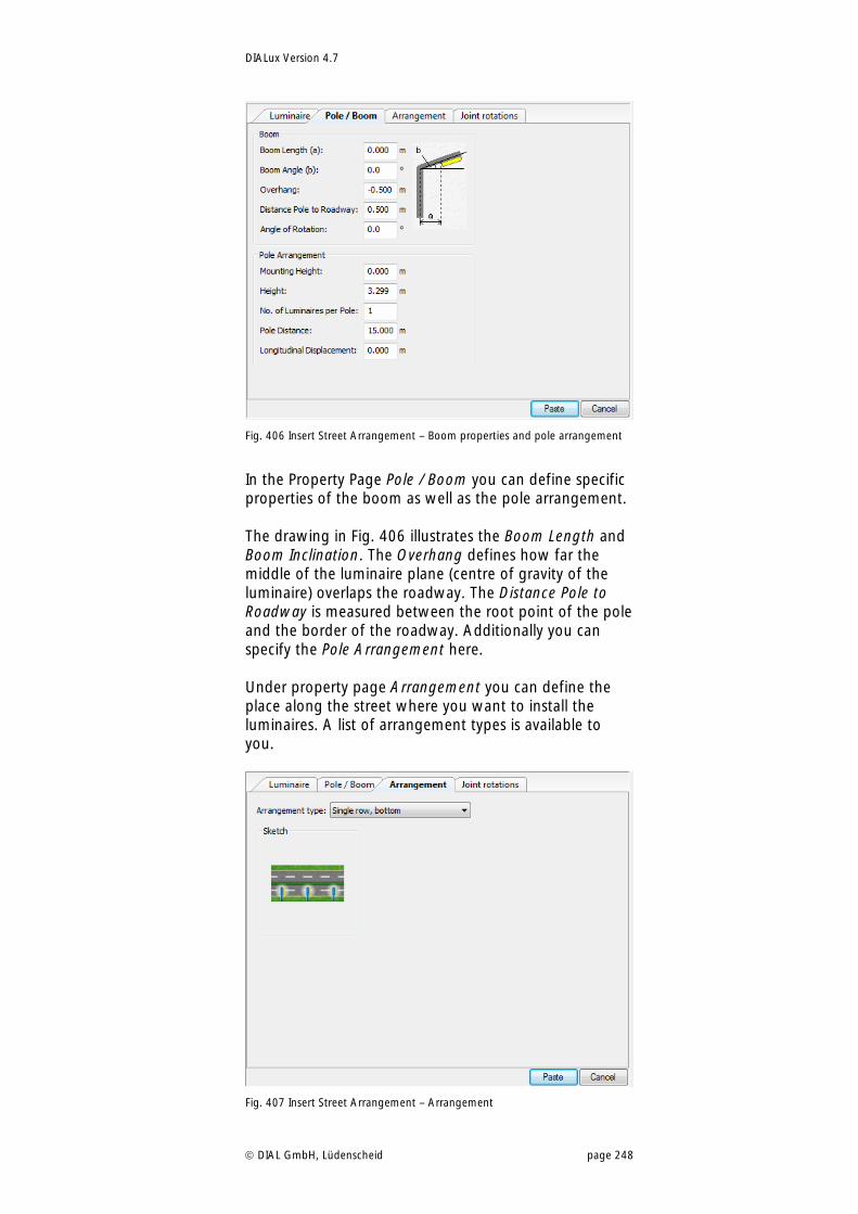
DIALux Version 4.7
DIAL GmbH, Lüdenscheid page 248
Fig. 406 Insert Street Arrangement – Boom properties and pole arrangement
In the Property Page Pole / Boom you can define specific properties of the boom as well as the pole arrangement. The drawing in Fig. 406 illustrates the Boom Length and Boom Inclination. The Overhang defines how far the middle of the luminaire plane (centre of gravity of the luminaire) overlaps the roadway. The Distance Pole to Roadway is measured between the root point of the pole and the border of the roadway. Additionally you can specify the Pole Arrangement here. Under property page Arrangement you can define the place along the street where you want to install the luminaires. A list of arrangement types is available to you.
Fig. 407 Insert Street Arrangement – Arrangement
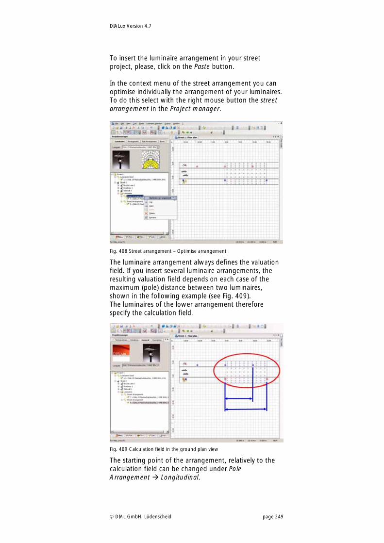
DIALux Version 4.7
DIAL GmbH, Lüdenscheid page 249
To insert the luminaire arrangement in your street project, please, click on the Paste button. In the context menu of the street arrangement you can optimise individually the arrangement of your luminaires. To do this select with the right mouse button the street arrangement in the Project manager.
Fig. 408 Street arrangement – Optimise arrangement
The luminaire arrangement always defines the valuation field. If you insert several luminaire arrangements, the resulting valuation field depends on each case of the maximum (pole) distance between two luminaires, shown in the following example (see Fig. 409). The luminaires of the lower arrangement therefore specify the calculation field.
Fig. 409 Calculation field in the ground plan view
The starting point of the arrangement, relatively to the calculation field can be changed under Pole Arrangement Longitudinal.
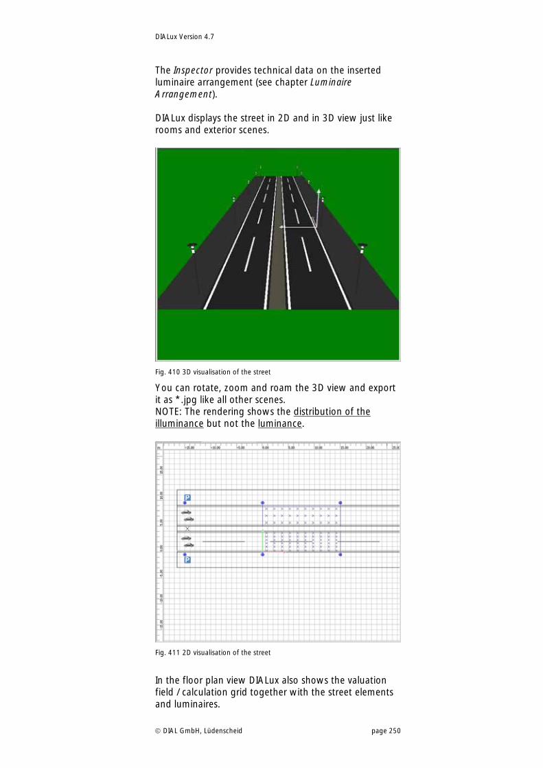
DIALux Version 4.7
DIAL GmbH, Lüdenscheid page 250
The Inspector provides technical data on the inserted luminaire arrangement (see chapter Luminaire Arrangement). DIALux displays the street in 2D and in 3D view just like rooms and exterior scenes.
Fig. 410 3D visualisation of the street
You can rotate, zoom and roam the 3D view and export it as *.jpg like all other scenes. NOTE: The rendering shows the distribution of the illuminance but not the luminance.
Fig. 411 2D visualisation of the street
In the floor plan view DIALux also shows the valuation field / calculation grid together with the street elements and luminaires.
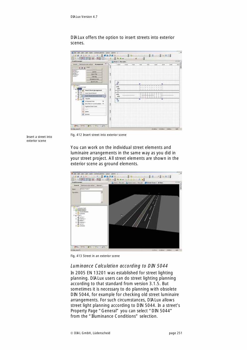
DIALux Version 4.7
DIAL GmbH, Lüdenscheid page 251
DIALux offers the option to insert streets into exterior scenes.
Fig. 412 Insert street into exterior scene
You can work on the individual street elements and luminaire arrangements in the same way as you did in your street project. All street elements are shown in the exterior scene as ground elements.
Fig. 413 Street in an exterior scene
Luminance Calculation according to DIN 5044 In 2005 EN 13201 was established for street lighting planning. DIALux users can do street lighting planning according to that standard from version 3.1.5. But sometimes it is necessary to do planning with obsolete DIN 5044, for example for checking old street luminaire arrangements. For such circumstances, DIALux allows street light planning according to DIN 5044. In a street’s Property Page “General” you can select “DIN 5044” from the “Illuminance Conditions” selection.
Insert a street into exterior scene
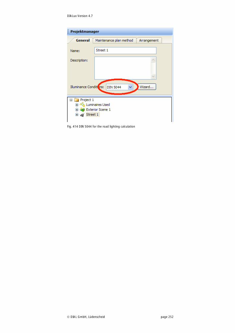
DIALux Version 4.7
DIAL GmbH, Lüdenscheid page 252
Fig. 414 DIN 5044 for the road lighting calculation
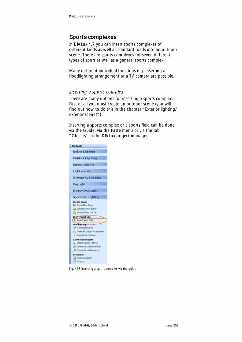
DIALux Version 4.7
DIAL GmbH, Lüdenscheid page 253
Sports complexes In DIALux 4.7 you can insert sports complexes of different kinds as well as standard roads into an outdoor scene. There are sports complexes for seven different types of sport as well as a general sports complex. Many different individual functions e.g. inserting a floodlighting arrangement or a TV camera are possible.
Inserting a sports complex There are many options for inserting a sports complex. First of all you must create an outdoor scene (you will find out how to do this in the chapter “Exterior lighting/ exterior scenes”) Inserting a sports complex or a sports field can be done via the Guide, via the Paste menu or via the tab “Objects” in the DIALux project manager.
Fig. 415 Inserting a sports complex via the guide
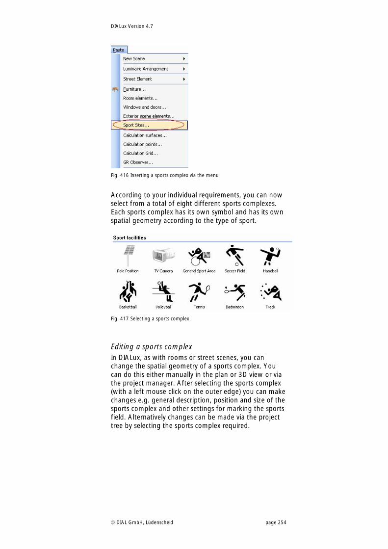
DIALux Version 4.7
DIAL GmbH, Lüdenscheid page 254
Fig. 416 Inserting a sports complex via the menu
According to your individual requirements, you can now select from a total of eight different sports complexes. Each sports complex has its own symbol and has its own spatial geometry according to the type of sport.
Fig. 417 Selecting a sports complex
Editing a sports complex In DIALux, as with rooms or street scenes, you can change the spatial geometry of a sports complex. You can do this either manually in the plan or 3D view or via the project manager. After selecting the sports complex (with a left mouse click on the outer edge) you can make changes e.g. general description, position and size of the sports complex and other settings for marking the sports field. Alternatively changes can be made via the project tree by selecting the sports complex required.
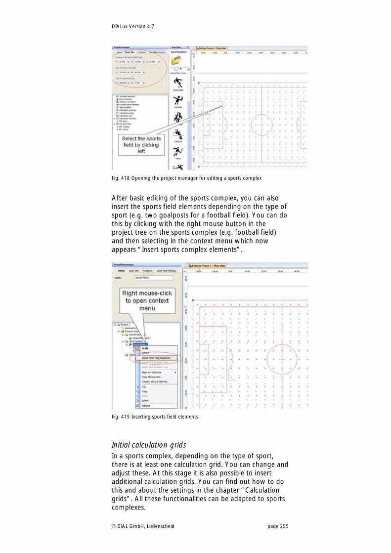
DIALux Version 4.7
DIAL GmbH, Lüdenscheid page 255
Fig. 418 Opening the project manager for editing a sports complex
After basic editing of the sports complex, you can also insert the sports field elements depending on the type of sport (e.g. two goalposts for a football field). You can do this by clicking with the right mouse button in the project tree on the sports complex (e.g. football field) and then selecting in the context menu which now appears “Insert sports complex elements”.
Fig. 419 Inserting sports field elements
Initial calculation grids In a sports complex, depending on the type of sport, there is at least one calculation grid. You can change and adjust these. At this stage it is also possible to insert additional calculation grids. You can find out how to do this and about the settings in the chapter “Calculation grids”. All these functionalities can be adapted to sports complexes.
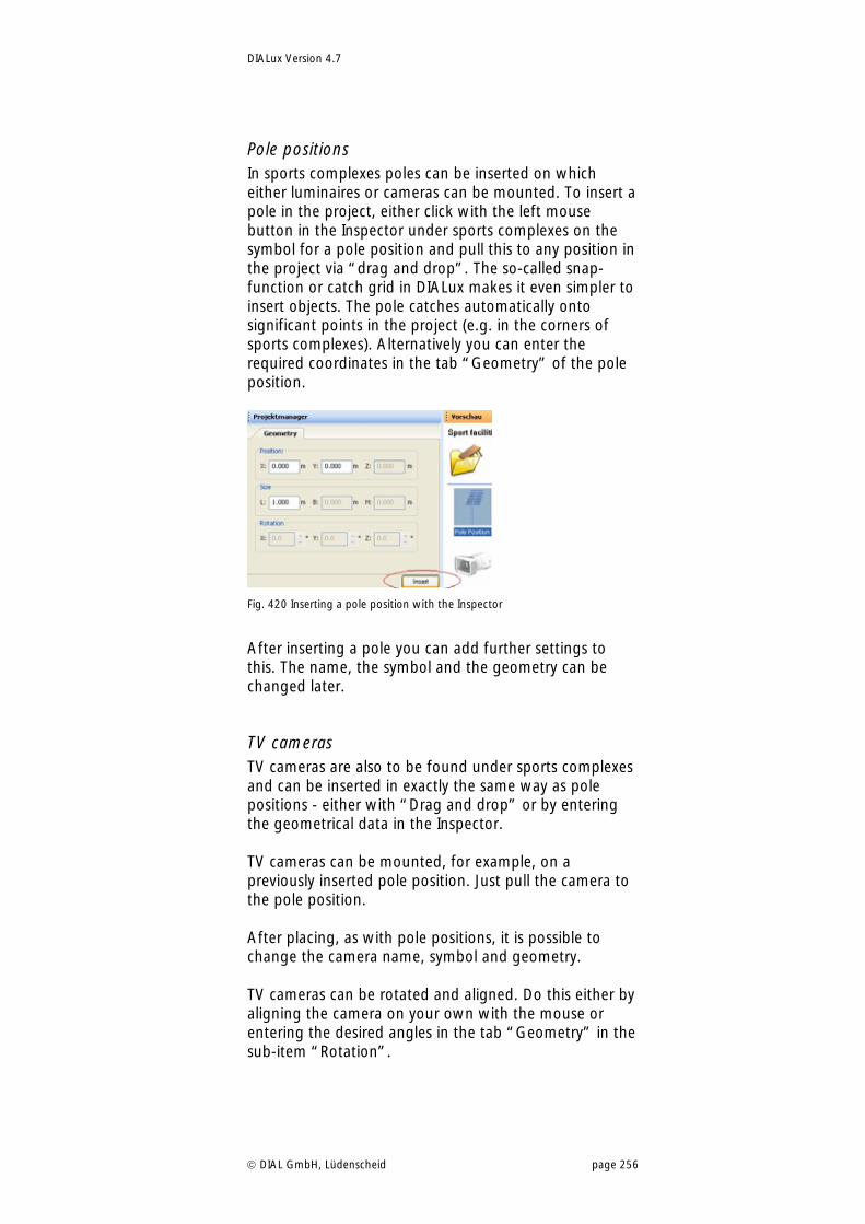
DIALux Version 4.7
DIAL GmbH, Lüdenscheid page 256
Pole positions In sports complexes poles can be inserted on which either luminaires or cameras can be mounted. To insert a pole in the project, either click with the left mouse button in the Inspector under sports complexes on the symbol for a pole position and pull this to any position in the project via “drag and drop”. The so-called snap-function or catch grid in DIALux makes it even simpler to insert objects. The pole catches automatically onto significant points in the project (e.g. in the corners of sports complexes). Alternatively you can enter the required coordinates in the tab “Geometry” of the pole position.
Fig. 420 Inserting a pole position with the Inspector
After inserting a pole you can add further settings to this. The name, the symbol and the geometry can be changed later.
TV cameras TV cameras are also to be found under sports complexes and can be inserted in exactly the same way as pole positions - either with “Drag and drop” or by entering the geometrical data in the Inspector. TV cameras can be mounted, for example, on a previously inserted pole position. Just pull the camera to the pole position. After placing, as with pole positions, it is possible to change the camera name, symbol and geometry. TV cameras can be rotated and aligned. Do this either by aligning the camera on your own with the mouse or entering the desired angles in the tab “Geometry” in the sub-item “Rotation”.
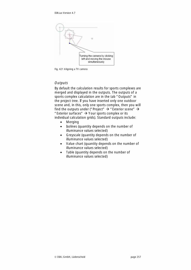
DIALux Version 4.7
DIAL GmbH, Lüdenscheid page 257
Fig. 421 Aligning a TV camera
Outputs By default the calculation results for sports complexes are merged and displayed in the outputs. The outputs of a sports complex calculation are in the tab “Outputs” in the project tree. If you have inserted only one outdoor scene and, in this, only one sports complex, then you will find the outputs under (“Project” “Exterior scene” “Exterior surfaces” Your sports complex or its individual calculation grids). Standard outputs include:
Merging Isolines (quantity depends on the number of
illuminance values selected) Greyscale (quantity depends on the number of
illuminance values selected) Value chart (quantity depends on the number of
illuminance values selected) Table (quantity depends on the number of
illuminance values selected)
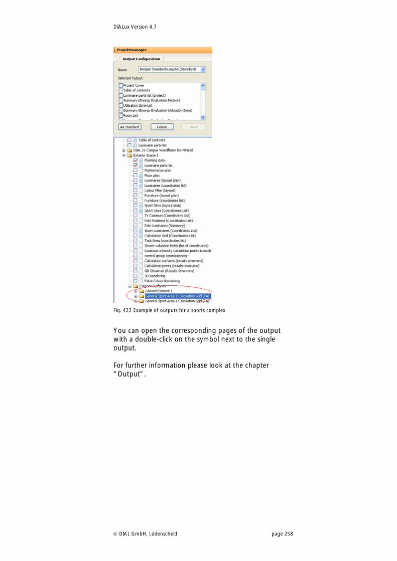
DIALux Version 4.7
DIAL GmbH, Lüdenscheid page 258
Fig. 422 Example of outputs for a sports complex
You can open the corresponding pages of the output with a double-click on the symbol next to the single output. For further information please look at the chapter “Output”.
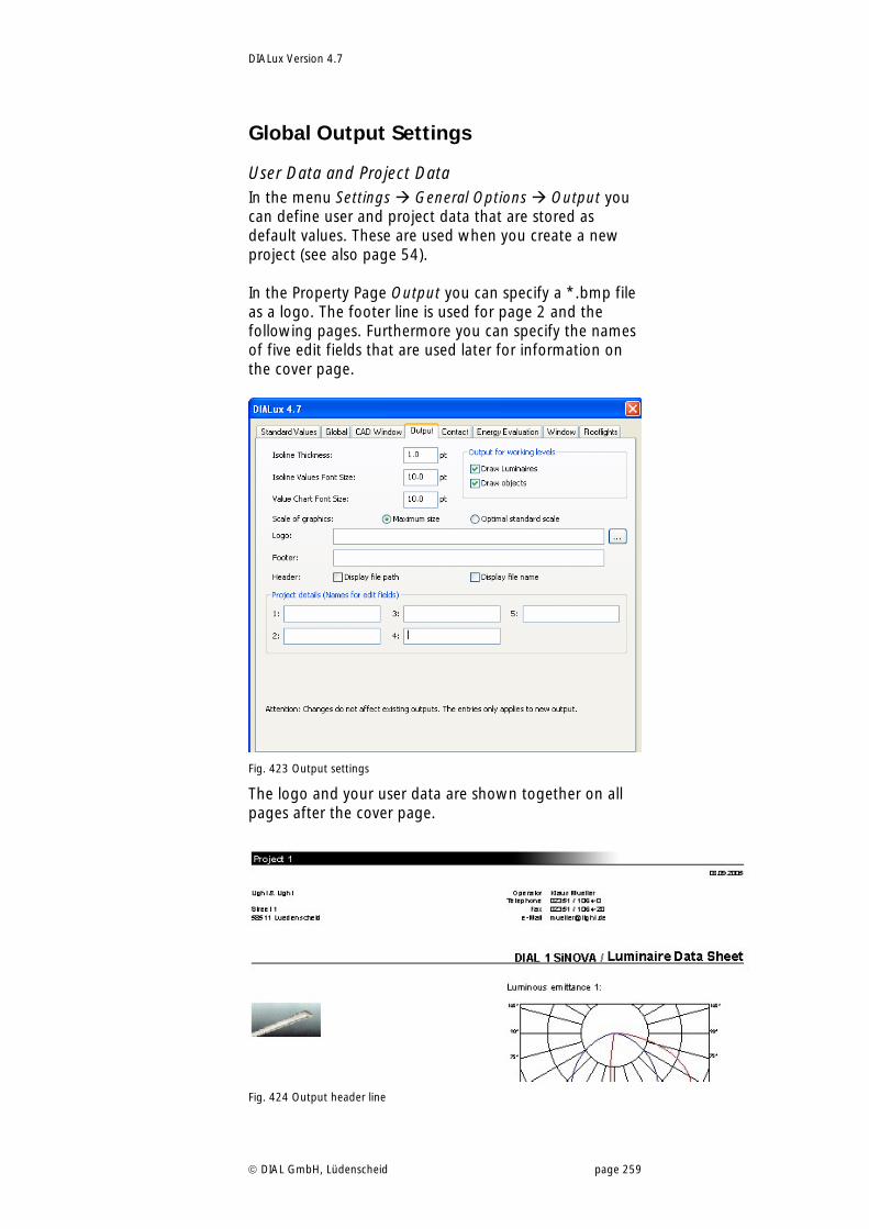
DIALux Version 4.7
DIAL GmbH, Lüdenscheid page 259
Global Output Settings
User Data and Project Data In the menu Settings General Options Output you can define user and project data that are stored as default values. These are used when you create a new project (see also page 54). In the Property Page Output you can specify a *.bmp file as a logo. The footer line is used for page 2 and the following pages. Furthermore you can specify the names of five edit fields that are used later for information on the cover page.
Fig. 423 Output settings
The logo and your user data are shown together on all pages after the cover page.
Fig. 424 Output header line
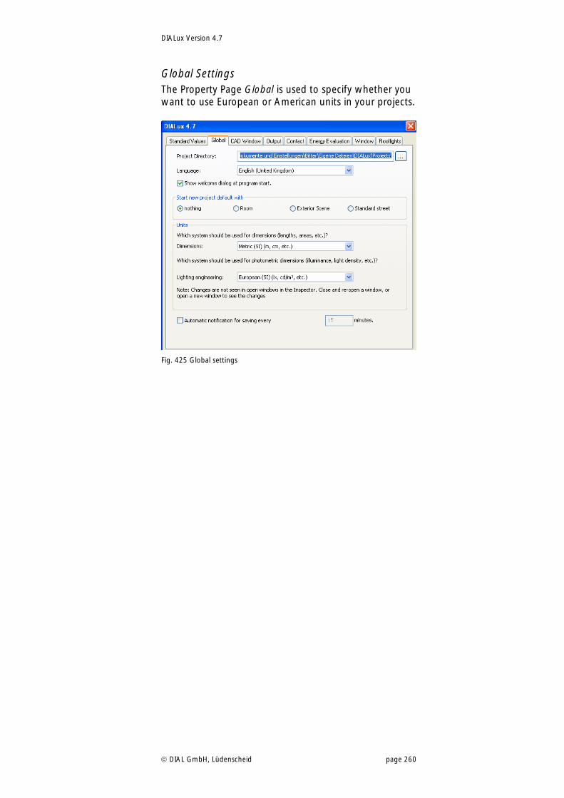
DIALux Version 4.7
DIAL GmbH, Lüdenscheid page 260
Global Settings The Property Page Global is used to specify whether you want to use European or American units in your projects.
Fig. 425 Global settings
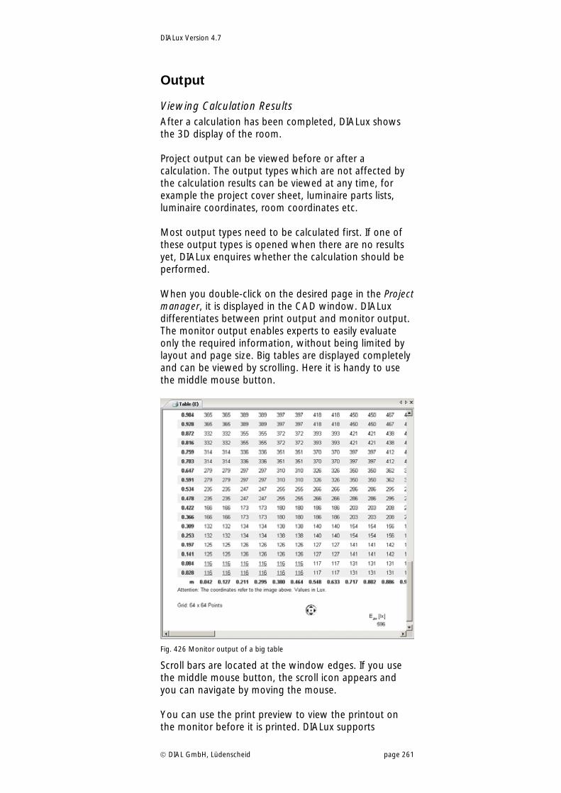
DIALux Version 4.7
DIAL GmbH, Lüdenscheid page 261
Output
Viewing Calculation Results After a calculation has been completed, DIALux shows the 3D display of the room. Project output can be viewed before or after a calculation. The output types which are not affected by the calculation results can be viewed at any time, for example the project cover sheet, luminaire parts lists, luminaire coordinates, room coordinates etc. Most output types need to be calculated first. If one of these output types is opened when there are no results yet, DIALux enquires whether the calculation should be performed. When you double-click on the desired page in the Project manager, it is displayed in the CAD window. DIALux differentiates between print output and monitor output. The monitor output enables experts to easily evaluate only the required information, without being limited by layout and page size. Big tables are displayed completely and can be viewed by scrolling. Here it is handy to use the middle mouse button.
Fig. 426 Monitor output of a big table
Scroll bars are located at the window edges. If you use the middle mouse button, the scroll icon appears and you can navigate by moving the mouse. You can use the print preview to view the printout on the monitor before it is printed. DIALux supports
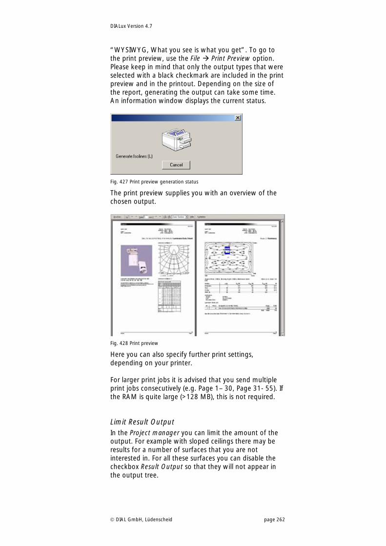
DIALux Version 4.7
DIAL GmbH, Lüdenscheid page 262
“WYSIWYG, What you see is what you get”. To go to the print preview, use the File Print Preview option. Please keep in mind that only the output types that were selected with a black checkmark are included in the print preview and in the printout. Depending on the size of the report, generating the output can take some time. An information window displays the current status.
Fig. 427 Print preview generation status
The print preview supplies you with an overview of the chosen output.
Fig. 428 Print preview
Here you can also specify further print settings, depending on your printer. For larger print jobs it is advised that you send multiple print jobs consecutively (e.g. Page 1– 30, Page 31- 55). If the RAM is quite large (>128 MB), this is not required.
Limit Result Output In the Project manager you can limit the amount of the output. For example with sloped ceilings there may be results for a number of surfaces that you are not interested in. For all these surfaces you can disable the checkbox Result Output so that they will not appear in the output tree.
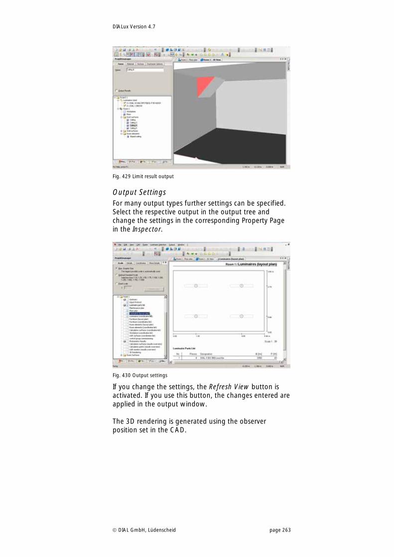
DIALux Version 4.7
DIAL GmbH, Lüdenscheid page 263
Fig. 429 Limit result output
Output Settings For many output types further settings can be specified. Select the respective output in the output tree and change the settings in the corresponding Property Page in the Inspector.
Fig. 430 Output settings
If you change the settings, the Refresh View button is activated. If you use this button, the changes entered are applied in the output window. The 3D rendering is generated using the observer position set in the CAD.
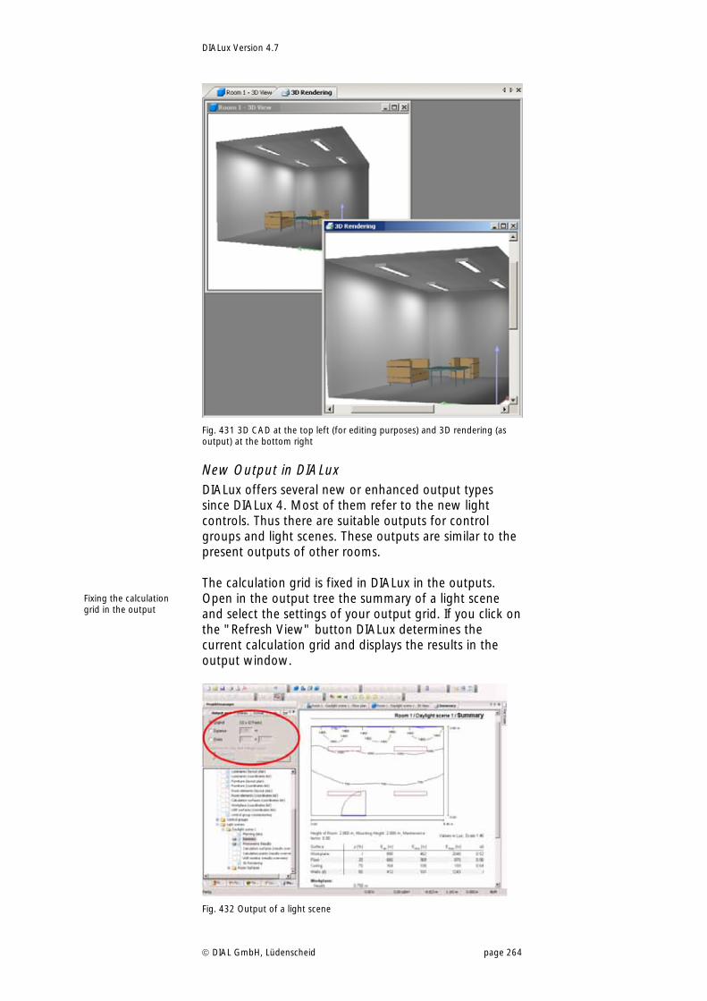
DIALux Version 4.7
DIAL GmbH, Lüdenscheid page 264
Fig. 431 3D CAD at the top left (for editing purposes) and 3D rendering (as output) at the bottom right
New Output in DIALux DIALux offers several new or enhanced output types since DIALux 4. Most of them refer to the new light controls. Thus there are suitable outputs for control groups and light scenes. These outputs are similar to the present outputs of other rooms. The calculation grid is fixed in DIALux in the outputs. Open in the output tree the summary of a light scene and select the settings of your output grid. If you click on the "Refresh View" button DIALux determines the current calculation grid and displays the results in the output window.
Fig. 432 Output of a light scene
Fixing the calculation grid in the output
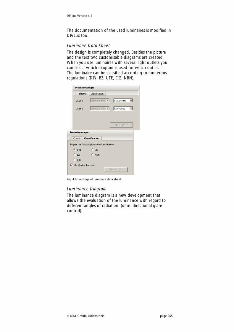
DIALux Version 4.7
DIAL GmbH, Lüdenscheid page 265
The documentation of the used luminaires is modified in DIALux too.
Luminaire Data Sheet The design is completely changed. Besides the picture and the text two customisable diagrams are created. When you use luminaires with several light outlets you can select which diagram is used for which outlet. The luminaire can be classified according to numerous regulations (DIN, BZ, UTE, CIE, NBN).
Fig. 433 Settings of luminaire data sheet
Luminance Diagram The luminance diagram is a new development that allows the evaluation of the luminance with regard to different angles of radiation (omni directional glare control).
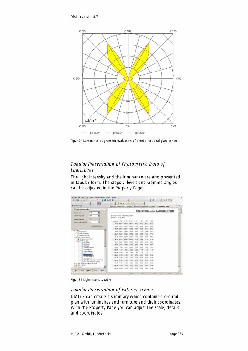
DIALux Version 4.7
DIAL GmbH, Lüdenscheid page 266
Fig. 434 Luminance diagram for evaluation of omni directional glare control
Tabular Presentation of Photometric Data of Luminaires The light intensity and the luminance are also presented in tabular form. The steps C-levels and Gamma angles can be adjusted in the Property Page.
Fig. 435 Light intensity table
Tabular Presentation of Exterior Scenes DIALux can create a summary which contains a ground plan with luminaires and furniture and their coordinates. With the Property Page you can adjust the scale, details and coordinates.
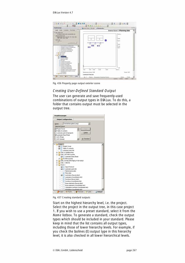
DIALux Version 4.7
DIAL GmbH, Lüdenscheid page 267
Fig. 436 Property page output exterior scene
Creating User-Defined Standard Output The user can generate and save frequently-used combinations of output types in DIALux. To do this, a folder that contains output must be selected in the output tree.
Fig. 437 Creating standard outputs
Start on the highest hierarchy level, i.e. the project. Select the project in the output tree, in this case project 1. If you wish to use a preset standard, select it from the Name listbox. To generate a standard, check the output types which should be included in your standard. Please keep in mind that the list contains all output types, including those of lower hierarchy levels. For example, if you check the Isolines (E) output type in this hierarchy level, it is also checked in all lower hierarchical levels.
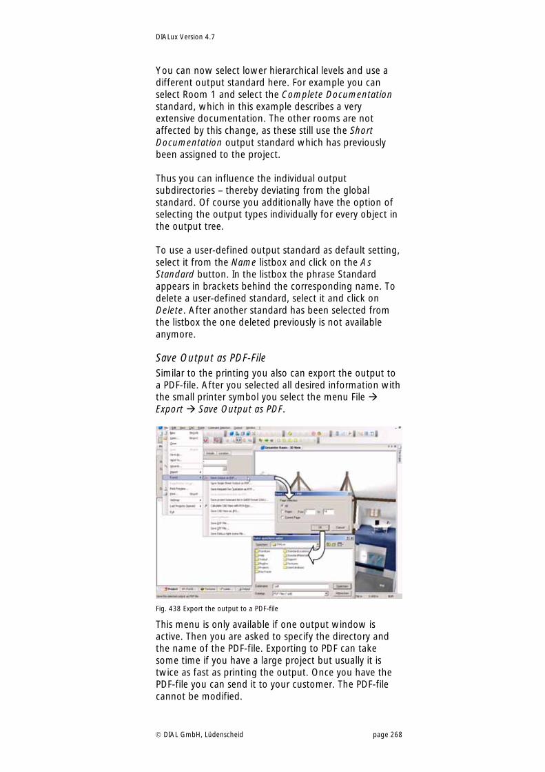
DIALux Version 4.7
DIAL GmbH, Lüdenscheid page 268
You can now select lower hierarchical levels and use a different output standard here. For example you can select Room 1 and select the Complete Documentation standard, which in this example describes a very extensive documentation. The other rooms are not affected by this change, as these still use the Short Documentation output standard which has previously been assigned to the project. Thus you can influence the individual output subdirectories – thereby deviating from the global standard. Of course you additionally have the option of selecting the output types individually for every object in the output tree. To use a user-defined output standard as default setting, select it from the Name listbox and click on the As Standard button. In the listbox the phrase Standard appears in brackets behind the corresponding name. To delete a user-defined standard, select it and click on Delete. After another standard has been selected from the listbox the one deleted previously is not available anymore.
Save Output as PDF-File Similar to the printing you also can export the output to a PDF-file. After you selected all desired information with the small printer symbol you select the menu File Export Save Output as PDF.
Fig. 438 Export the output to a PDF-file
This menu is only available if one output window is active. Then you are asked to specify the directory and the name of the PDF-file. Exporting to PDF can take some time if you have a large project but usually it is twice as fast as printing the output. Once you have the PDF-file you can send it to your customer. The PDF-file cannot be modified.
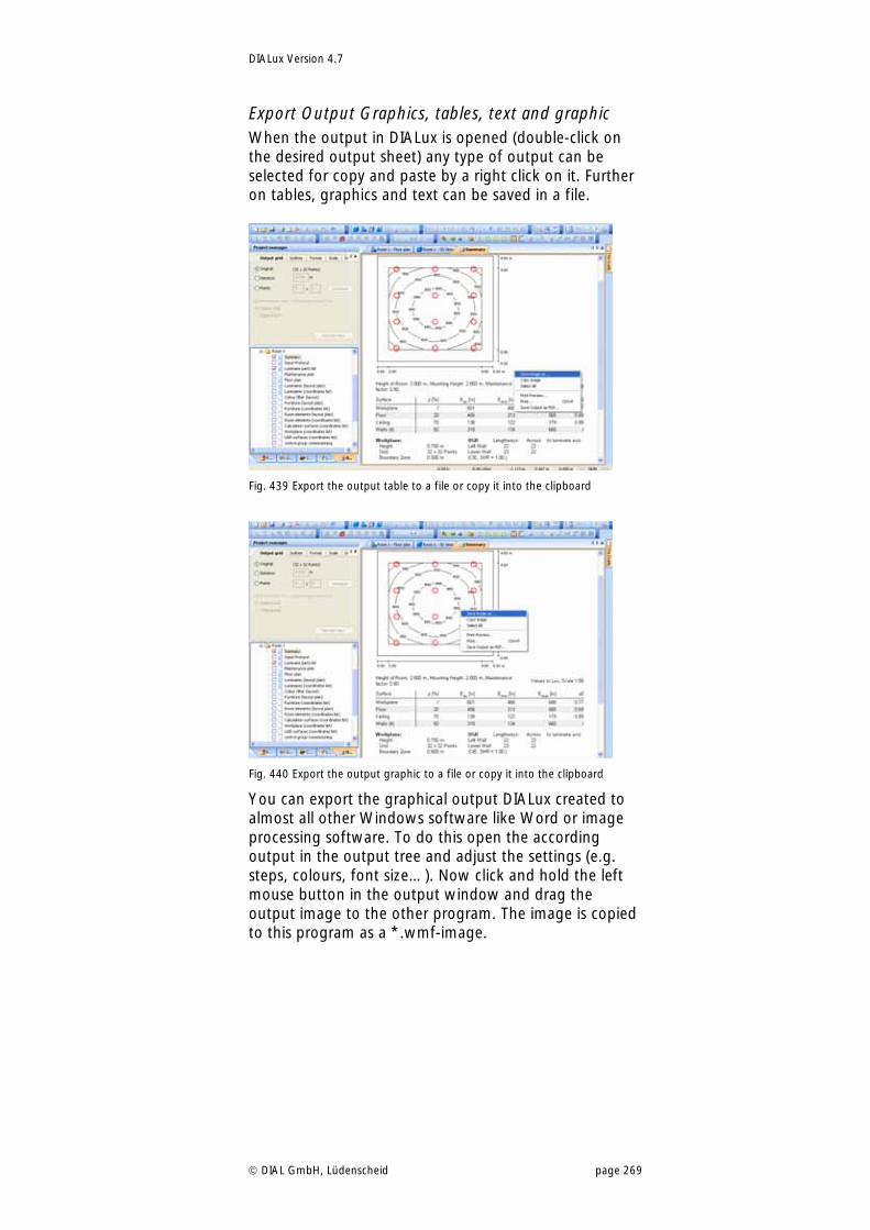
DIALux Version 4.7
DIAL GmbH, Lüdenscheid page 269
Export Output Graphics, tables, text and graphic When the output in DIALux is opened (double-click on the desired output sheet) any type of output can be selected for copy and paste by a right click on it. Further on tables, graphics and text can be saved in a file.
Fig. 439 Export the output table to a file or copy it into the clipboard
Fig. 440 Export the output graphic to a file or copy it into the clipboard
You can export the graphical output DIALux created to almost all other Windows software like Word or image processing software. To do this open the according output in the output tree and adjust the settings (e.g. steps, colours, font size…). Now click and hold the left mouse button in the output window and drag the output image to the other program. The image is copied to this program as a *.wmf-image.
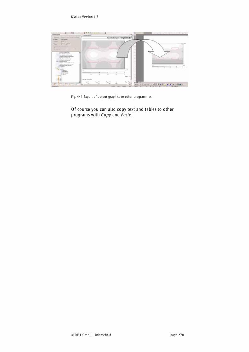
DIALux Version 4.7
DIAL GmbH, Lüdenscheid page 270
Fig. 441 Export of output graphics to other programmes
Of course you can also copy text and tables to other programs with Copy and Paste.
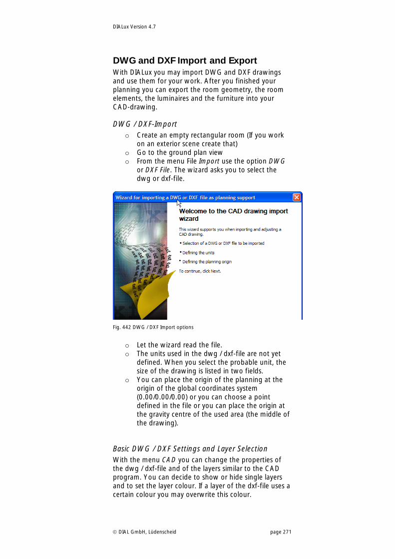
DIALux Version 4.7
DIAL GmbH, Lüdenscheid page 271
DWG and DXF Import and Export With DIALux you may import DWG and DXF drawings and use them for your work. After you finished your planning you can export the room geometry, the room elements, the luminaires and the furniture into your CAD-drawing.
DWG / DXF-Import o Create an empty rectangular room (If you work
on an exterior scene create that) o Go to the ground plan view o From the menu File Import use the option DWG
or DXF File. The wizard asks you to select the dwg or dxf-file.
Fig. 442 DWG / DXF Import options
o Let the wizard read the file. o The units used in the dwg / dxf-file are not yet
defined. When you select the probable unit, the size of the drawing is listed in two fields.
o You can place the origin of the planning at the origin of the global coordinates system (0.00/0.00/0.00) or you can choose a point defined in the file or you can place the origin at the gravity centre of the used area (the middle of the drawing).
Basic DWG / DXF Settings and Layer Selection With the menu CAD you can change the properties of the dwg / dxf-file and of the layers similar to the CAD program. You can decide to show or hide single layers and to set the layer colour. If a layer of the dxf-file uses a certain colour you may overwrite this colour.
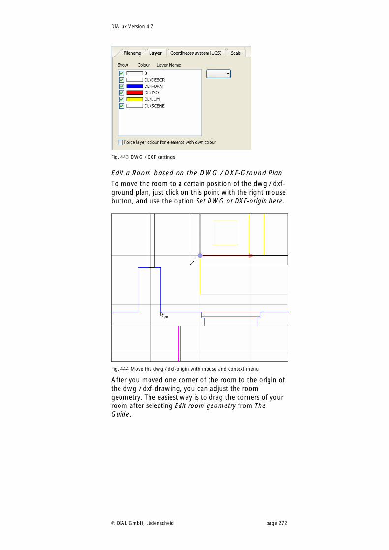
DIALux Version 4.7
DIAL GmbH, Lüdenscheid page 272
Fig. 443 DWG / DXF settings
Edit a Room based on the DWG / DXF-Ground Plan To move the room to a certain position of the dwg / dxf-ground plan, just click on this point with the right mouse button, and use the option Set DWG or DXF-origin here.
Fig. 444 Move the dwg / dxf-origin with mouse and context menu
After you moved one corner of the room to the origin of the dwg / dxf-drawing, you can adjust the room geometry. The easiest way is to drag the corners of your room after selecting Edit room geometry from The Guide.
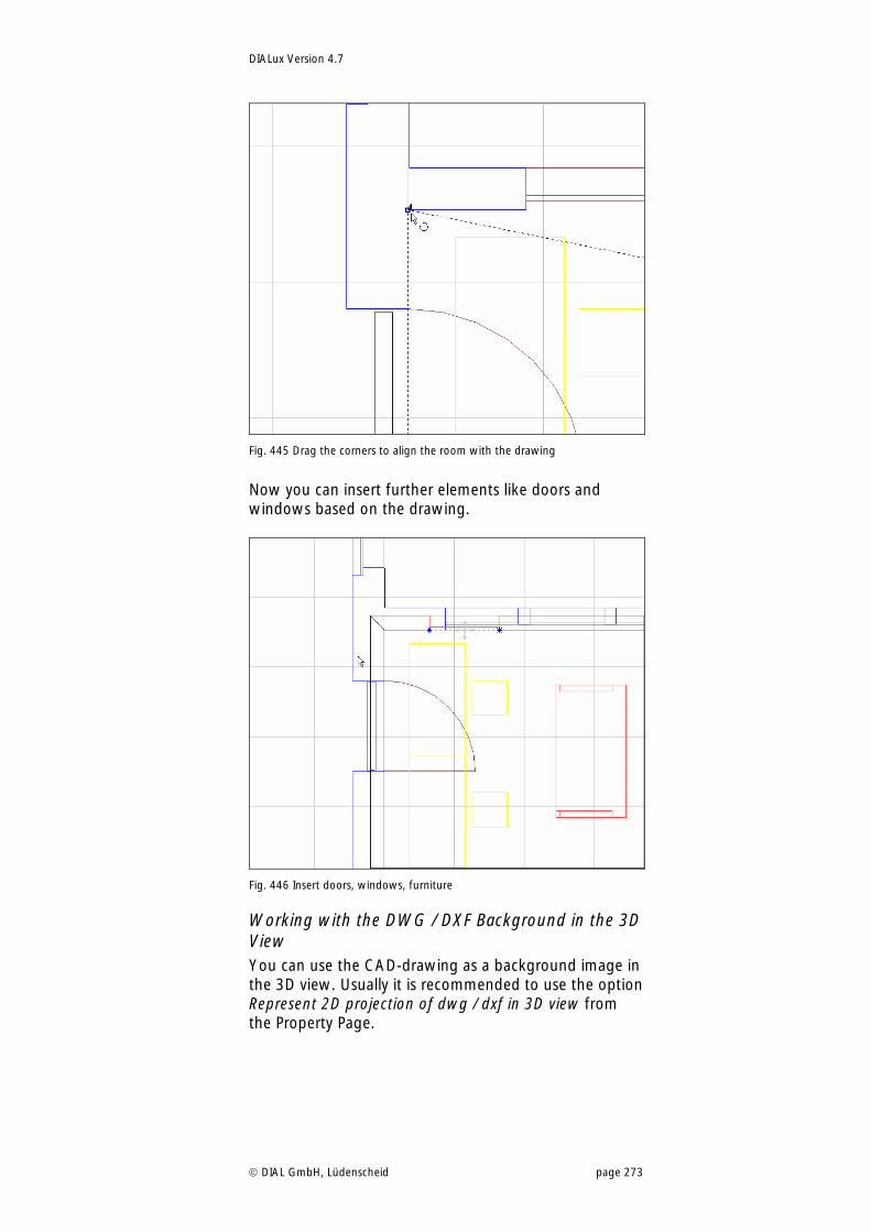
DIALux Version 4.7
DIAL GmbH, Lüdenscheid page 273
Fig. 445 Drag the corners to align the room with the drawing
Now you can insert further elements like doors and windows based on the drawing.
Fig. 446 Insert doors, windows, furniture
Working with the DWG / DXF Background in the 3D View You can use the CAD-drawing as a background image in the 3D view. Usually it is recommended to use the option Represent 2D projection of dwg / dxf in 3D view from the Property Page.
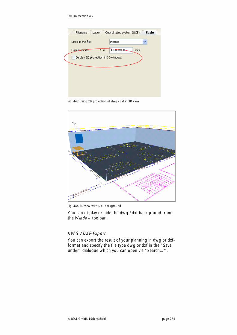
DIALux Version 4.7
DIAL GmbH, Lüdenscheid page 274
Fig. 447 Using 2D projection of dwg / dxf in 3D view
Fig. 448 3D view with DXF background
You can display or hide the dwg / dxf background from the Window toolbar.
DWG / DXF-Export You can export the result of your planning in dwg or dxf-format and specify the file type dwg or dxf in the “Save under“ dialogue which you can open via “Search…”.
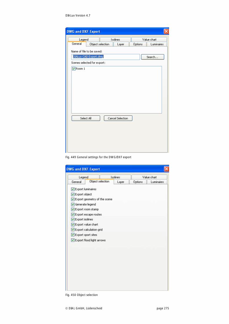
DIALux Version 4.7
DIAL GmbH, Lüdenscheid page 275
Fig. 449 General settings for the DWG/DXF export
Fig. 450 Object selection
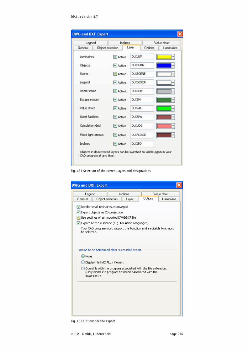
DIALux Version 4.7
DIAL GmbH, Lüdenscheid page 276
Fig. 451 Selection of the current layers and designations
Fig. 452 Options for the export
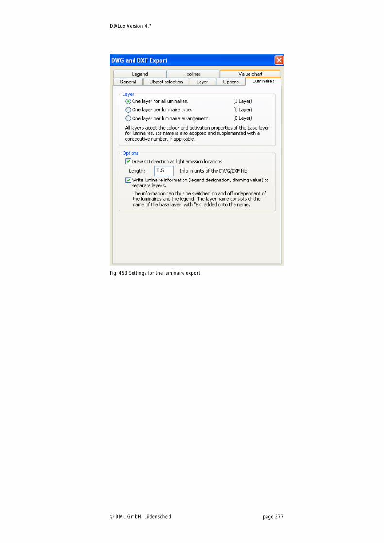
DIALux Version 4.7
DIAL GmbH, Lüdenscheid page 277
Fig. 453 Settings for the luminaire export
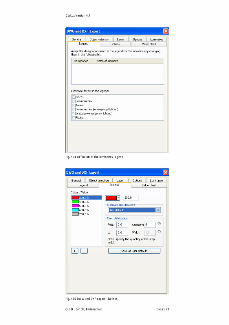
DIALux Version 4.7
DIAL GmbH, Lüdenscheid page 278
Fig. 454 Definition of the luminaires’ legend
Fig. 455 DWG and DXF export - Isolines

DIALux Version 4.7
DIAL GmbH, Lüdenscheid page 279
Fig. 456 Export of the value chart in dxf and dwg
You can specify the scope of the contents to be exported. The use of the settings of the original DWG or DXF file makes sense if you would like to integrate the DIALux planning there again.
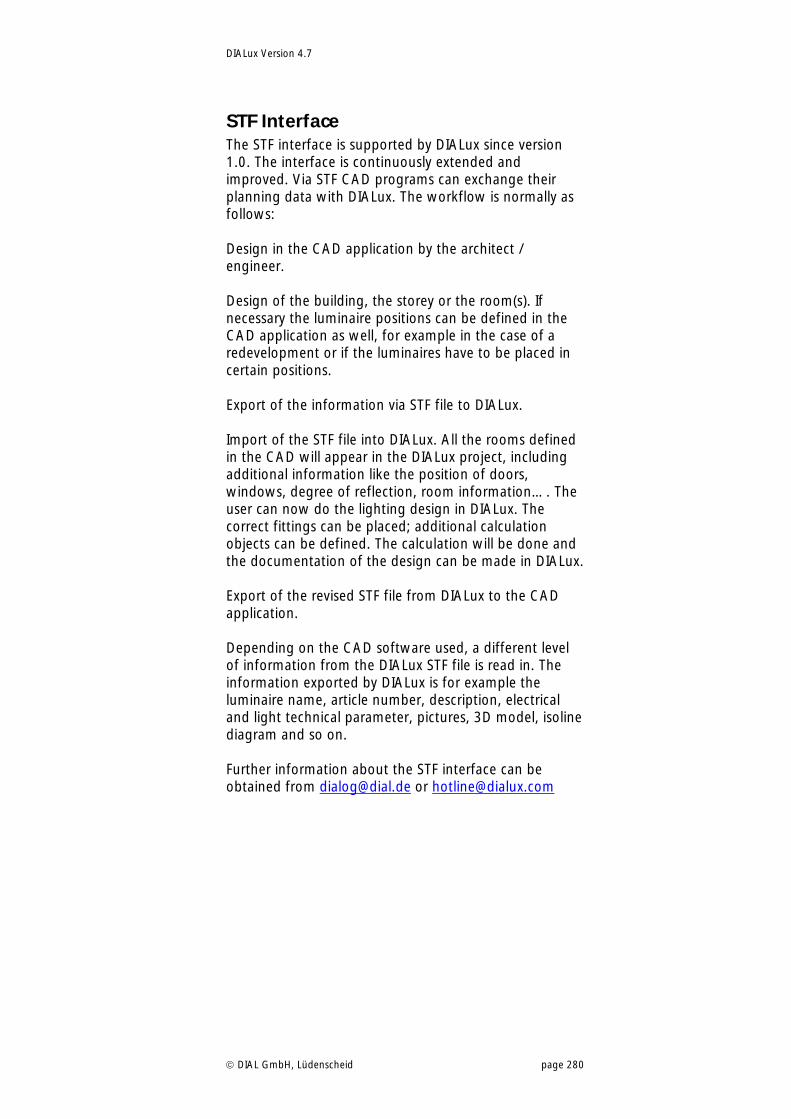
DIALux Version 4.7
DIAL GmbH, Lüdenscheid page 280
STF Interface The STF interface is supported by DIALux since version 1.0. The interface is continuously extended and improved. Via STF CAD programs can exchange their planning data with DIALux. The workflow is normally as follows: Design in the CAD application by the architect / engineer. Design of the building, the storey or the room(s). If necessary the luminaire positions can be defined in the CAD application as well, for example in the case of a redevelopment or if the luminaires have to be placed in certain positions. Export of the information via STF file to DIALux. Import of the STF file into DIALux. All the rooms defined in the CAD will appear in the DIALux project, including additional information like the position of doors, windows, degree of reflection, room information…. The user can now do the lighting design in DIALux. The correct fittings can be placed; additional calculation objects can be defined. The calculation will be done and the documentation of the design can be made in DIALux. Export of the revised STF file from DIALux to the CAD application. Depending on the CAD software used, a different level of information from the DIALux STF file is read in. The information exported by DIALux is for example the luminaire name, article number, description, electrical and light technical parameter, pictures, 3D model, isoline diagram and so on. Further information about the STF interface can be obtained from [email protected] or [email protected]
DIALux Version 4.7
DIAL GmbH, Lüdenscheid page 281
Energy Performance of Buildings
Background information Under the Kyoto protocol, Europe is committed seriously to reduce CO2 emissions. One instrument to achieve this is the directive 2002/91/EC “Energy Performance of Buildings Directive“of the European Parliament and Council. The directive’s requirements hold for both new and to be renovated buildings and for both residential and non-residential buildings. Member states of the EU were committed to implement this directive into national right. As a guideline the EU created a general framework for the calculation of energy performances of buildings, which stated which aspects the calculation methodology must at least include. These aspects are heating, ventilation, air-conditioning, hot water supply and lighting. To support the implementation of the directive in the EU member states, the European committee for standardization CEN created a set of CEN standards. This set consists of more than 30 parts, includes more than 40 standards and drafts and covers 5 CEN technical committees. A good overview can be found in http://www.buildingsplatform.eu/epbd_publication/doc/P02_EPBD_CEN_Standards_p2370.pdf. The part concerning lighting is EN 15193: “Energy performance of buildings – Energy requirements for lighting“. Besides the European implementation there are national implementations, for example in Germany the DIN 18599: “Energy efficiency of buildings”. This standard uses an integral approach for the calculation of the energy balance. That is a joint evaluation of energy demands for all parts of the building (heating, ventilation, air conditioning, cooling, humidification, domestic hot water and lighting), taking into account interactions between them and impacts on others. For example, the energy consumption for lighting is not only part of the energy balance for lighting, but also an inner heating source and so an important part of heating and cooling. For more information about the directive please visit site www.buildingsplatform.eu. This site really covers everything about the directive that is worth knowing.
Why energy evaluation in DIALux? In the medium term, the energy performance for buildings directive means more work for lighting designers. Besides the well known lighting data
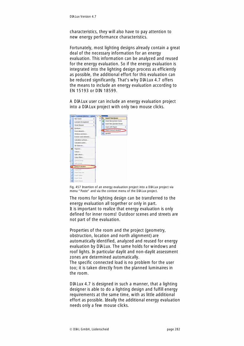
DIALux Version 4.7
DIAL GmbH, Lüdenscheid page 282
characteristics, they will also have to pay attention to new energy performance characteristics. Fortunately, most lighting designs already contain a great deal of the necessary information for an energy evaluation. This information can be analyzed and reused for the energy evaluation. So if the energy evaluation is integrated into the lighting design process as efficiently as possible, the additional effort for this evaluation can be reduced significantly. That’s why DIALux 4.7 offers the means to include an energy evaluation according to EN 15193 or DIN 18599. A DIALux user can include an energy evaluation project into a DIALux project with only two mouse clicks.
Fig. 457 Insertion of an energy evaluation project into a DIALux project via menu “Paste“ and via the context menu of the DIALux project.
The rooms for lighting design can be transferred to the energy evaluation all together or only in part. It is important to realize that energy evaluation is only defined for inner rooms! Outdoor scenes and streets are not part of the evaluation. Properties of the room and the project (geometry, obstruction, location and north alignment) are automatically identified, analyzed and reused for energy evaluation by DIALux. The same holds for windows and roof lights. In particular daylit and non-daylit assessment zones are determined automatically. The specific connected load is no problem for the user too; it is taken directly from the planned luminaires in the room. DIALux 4.7 is designed in such a manner, that a lighting designer is able to do a lighting design and fulfill energy requirements at the same time, with as little additional effort as possible. Ideally the additional energy evaluation needs only a few mouse clicks.
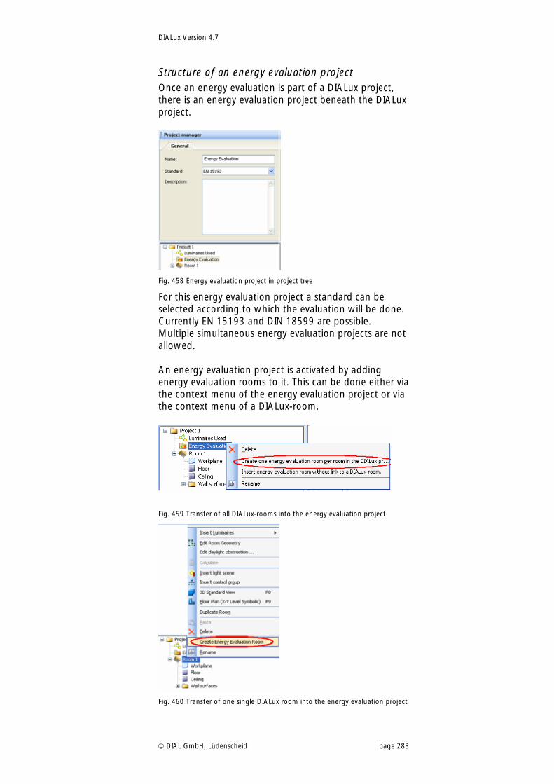
DIALux Version 4.7
DIAL GmbH, Lüdenscheid page 283
Structure of an energy evaluation project Once an energy evaluation is part of a DIALux project, there is an energy evaluation project beneath the DIALux project.
Fig. 458 Energy evaluation project in project tree
For this energy evaluation project a standard can be selected according to which the evaluation will be done. Currently EN 15193 and DIN 18599 are possible. Multiple simultaneous energy evaluation projects are not allowed. An energy evaluation project is activated by adding energy evaluation rooms to it. This can be done either via the context menu of the energy evaluation project or via the context menu of a DIALux-room.
Fig. 459 Transfer of all DIALux-rooms into the energy evaluation project
Fig. 460 Transfer of one single DIALux room into the energy evaluation project
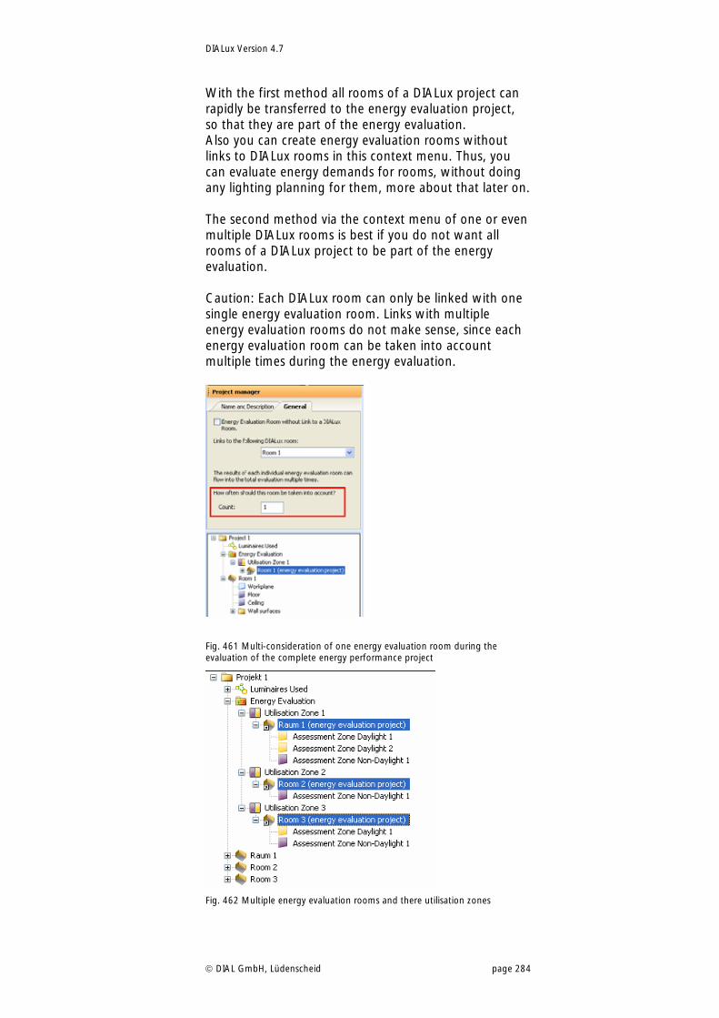
DIALux Version 4.7
DIAL GmbH, Lüdenscheid page 284
With the first method all rooms of a DIALux project can rapidly be transferred to the energy evaluation project, so that they are part of the energy evaluation. Also you can create energy evaluation rooms without links to DIALux rooms in this context menu. Thus, you can evaluate energy demands for rooms, without doing any lighting planning for them, more about that later on. The second method via the context menu of one or even multiple DIALux rooms is best if you do not want all rooms of a DIALux project to be part of the energy evaluation. Caution: Each DIALux room can only be linked with one single energy evaluation room. Links with multiple energy evaluation rooms do not make sense, since each energy evaluation room can be taken into account multiple times during the energy evaluation.
Fig. 461 Multi-consideration of one energy evaluation room during the evaluation of the complete energy performance project
Fig. 462 Multiple energy evaluation rooms and there utilisation zones
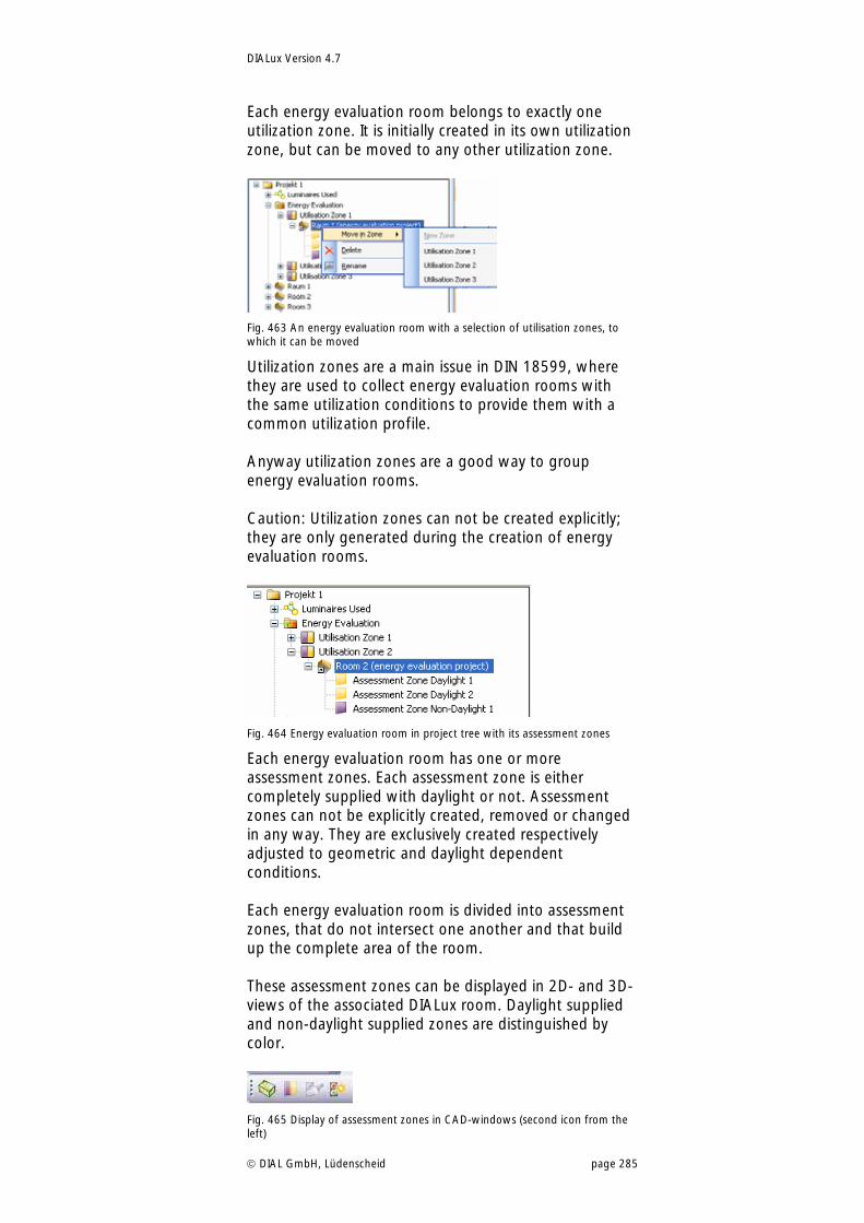
DIALux Version 4.7
DIAL GmbH, Lüdenscheid page 285
Each energy evaluation room belongs to exactly one utilization zone. It is initially created in its own utilization zone, but can be moved to any other utilization zone.
Fig. 463 An energy evaluation room with a selection of utilisation zones, to which it can be moved
Utilization zones are a main issue in DIN 18599, where they are used to collect energy evaluation rooms with the same utilization conditions to provide them with a common utilization profile. Anyway utilization zones are a good way to group energy evaluation rooms. Caution: Utilization zones can not be created explicitly; they are only generated during the creation of energy evaluation rooms.
Fig. 464 Energy evaluation room in project tree with its assessment zones
Each energy evaluation room has one or more assessment zones. Each assessment zone is either completely supplied with daylight or not. Assessment zones can not be explicitly created, removed or changed in any way. They are exclusively created respectively adjusted to geometric and daylight dependent conditions. Each energy evaluation room is divided into assessment zones, that do not intersect one another and that build up the complete area of the room. These assessment zones can be displayed in 2D- and 3D-views of the associated DIALux room. Daylight supplied and non-daylight supplied zones are distinguished by color.
Fig. 465 Display of assessment zones in CAD-windows (second icon from the left)
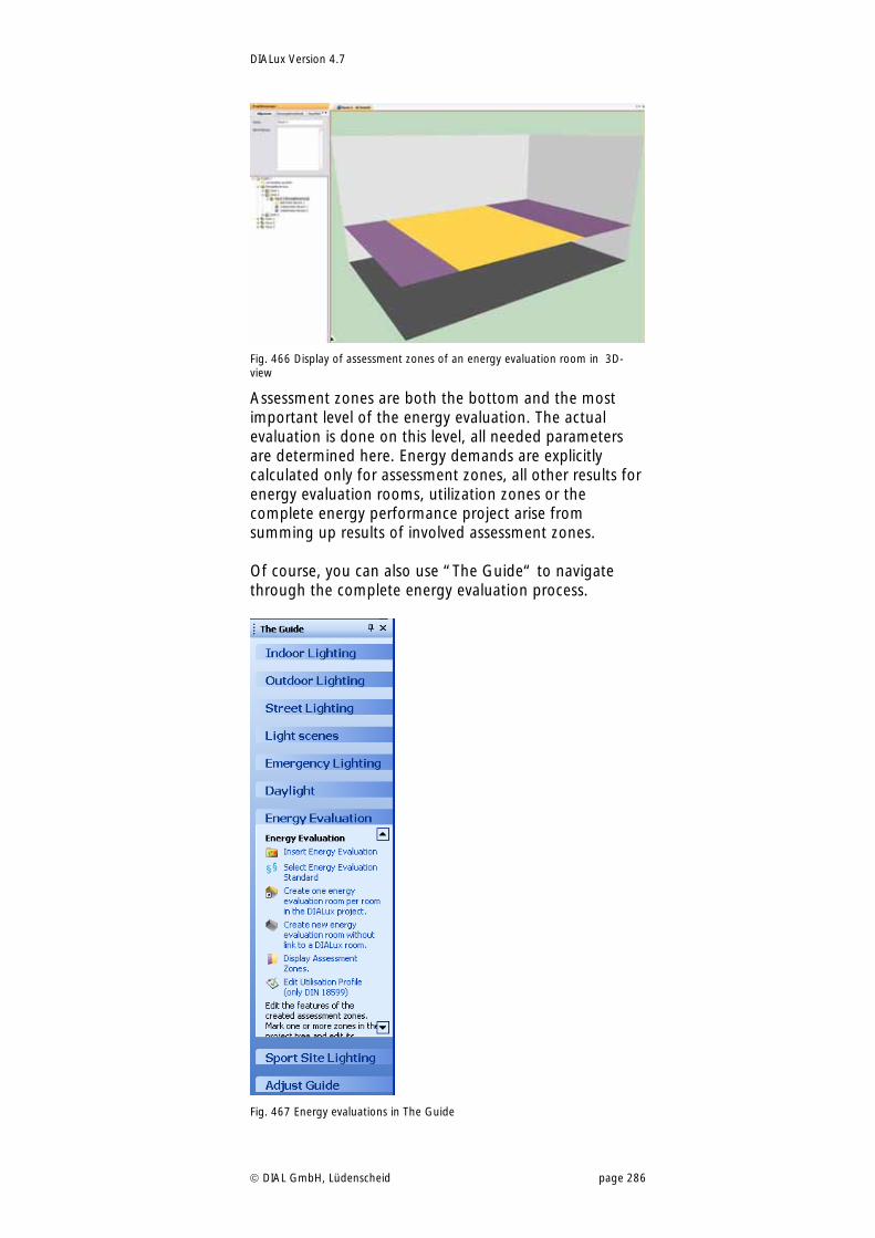
DIALux Version 4.7
DIAL GmbH, Lüdenscheid page 286
Fig. 466 Display of assessment zones of an energy evaluation room in 3D-view
Assessment zones are both the bottom and the most important level of the energy evaluation. The actual evaluation is done on this level, all needed parameters are determined here. Energy demands are explicitly calculated only for assessment zones, all other results for energy evaluation rooms, utilization zones or the complete energy performance project arise from summing up results of involved assessment zones. Of course, you can also use “The Guide“ to navigate through the complete energy evaluation process.
Fig. 467 Energy evaluations in The Guide
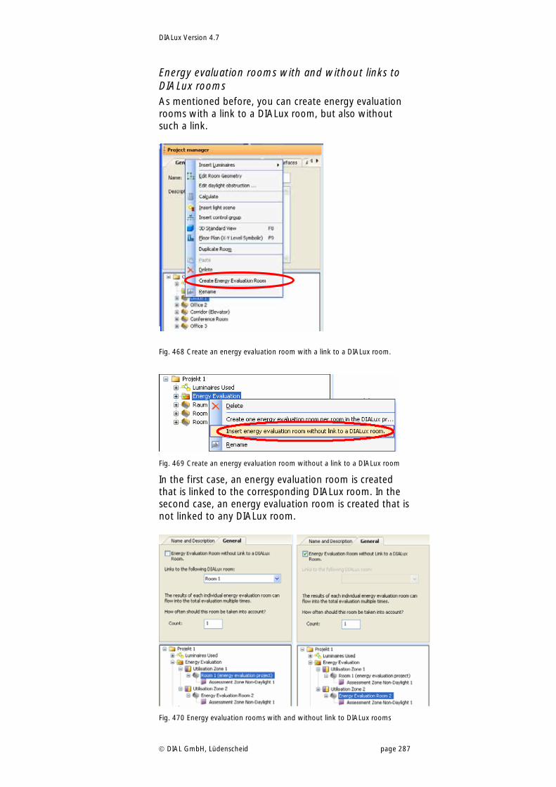
DIALux Version 4.7
DIAL GmbH, Lüdenscheid page 287
Energy evaluation rooms with and without links to DIALux rooms As mentioned before, you can create energy evaluation rooms with a link to a DIALux room, but also without such a link.
Fig. 468 Create an energy evaluation room with a link to a DIALux room.
Fig. 469 Create an energy evaluation room without a link to a DIALux room
In the first case, an energy evaluation room is created that is linked to the corresponding DIALux room. In the second case, an energy evaluation room is created that is not linked to any DIALux room.
Fig. 470 Energy evaluation rooms with and without link to DIALux rooms

DIALux Version 4.7
DIAL GmbH, Lüdenscheid page 288
The linking of energy evaluation rooms and DIALux rooms has many advantages. Many aspects of the started or completed light planning can be automatically transferred to the energy evaluation with such links. The complete geometry of the DIALux room is analyzed for the energy evaluation, and this does not only mean the ground area and height, but even the daylight relevant information like position and properties of windows and roof lights, the orientation (north alignment) and obstruction, etc. One of the most important steps during energy evaluation, the determination of daylight supplied assessment zones, happens completely automatically. All technical information about luminaries and lamps are transferred as well. You do not need to think about mapping of total power values of luminaires and associated parasitic power values to assessment zones or even use some table or rough calculation methods to get such power values. All lighting data is determined from the light planning and assigned to the energy evaluation. And the advantages are not limited to the creation of energy evaluation rooms and their assessment zones. A comprehensive update mechanism makes sure that changes to all relevant data of the light planning will be passed on to the energy evaluation as well. So the energy evaluation is always up to date and simultaneous planning is possible. Nevertheless, for a lot of details it makes sense, to have them well designed before a link is created. That’s because DIALux tries to initialise all of the parameters of the energy evaluation room and its assessment zones as well as possible, so that the user has to do as little adjustments as possible. And the better the starting position the better the initialisations. There is another important reason to do as much preliminary work as possible. As said before there is an update mechanism between light planning and energy evaluation, that reacts on subsequent changes. This update mechanism not only changes properties of assessment zones, it also may create new assessment zones and delete old ones. The new zones are once again initialised as well as possible by DIALux, but must again be checked and adjusted where applicable by the user. The old zones are deleted making the time spent checking and adjusting their properties is wasted.
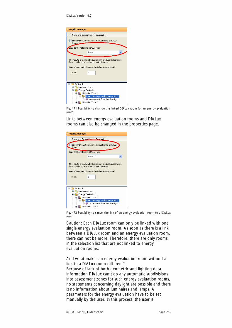
DIALux Version 4.7
DIAL GmbH, Lüdenscheid page 289
Fig. 471 Possibility to change the linked DIALux room for an energy evaluation room
Links between energy evaluation rooms and DIALux rooms can also be changed in the properties page.
Fig. 472 Possibility to cancel the link of an energy evaluation room to a DIALux room
Caution: Each DIALux room can only be linked with one single energy evaluation room. As soon as there is a link between a DIALux room and an energy evaluation room, there can not be more. Therefore, there are only rooms in the selection list that are not linked to energy evaluation rooms. And what makes an energy evaluation room without a link to a DIALux room different? Because of lack of both geometric and lighting data information DIALux can’t do any automatic subdivisions into assessment zones for such energy evaluation rooms, no statements concerning daylight are possible and there is no information about luminaires and lamps. All parameters for the energy evaluation have to be set manually by the user. In this process, the user is
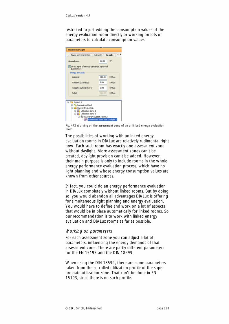
DIALux Version 4.7
DIAL GmbH, Lüdenscheid page 290
restricted to just editing the consumption values of the energy evaluation room directly or working on lots of parameters to calculate consumption values.
Fig. 473 Working on the assessment zone of an unlinked energy evaluation room
The possibilities of working with unlinked energy evaluation rooms in DIALux are relatively rudimental right now. Each such room has exactly one assessment zone without daylight. More assessment zones can’t be created, daylight provision can’t be added. However, their main purpose is only to include rooms in the whole energy performance evaluation process, which have no light planning and whose energy consumption values are known from other sources. In fact, you could do an energy performance evaluation in DIALux completely without linked rooms. But by doing so, you would abandon all advantages DIALux is offering for simultaneous light planning and energy evaluation. You would have to define and work on a lot of aspects that would be in place automatically for linked rooms. So our recommendation is to work with linked energy evaluation and DIALux rooms as far as possible.
Working on parameters For each assessment zone you can adjust a lot of parameters, influencing the energy demands of that assessment zone. There are partly different parameters for the EN 15193 and the DIN 18599. When using the DIN 18599, there are some parameters taken from the so called utilization profile of the super ordinate utilization zone. That can’t be done in EN 15193, since there is no such profile.
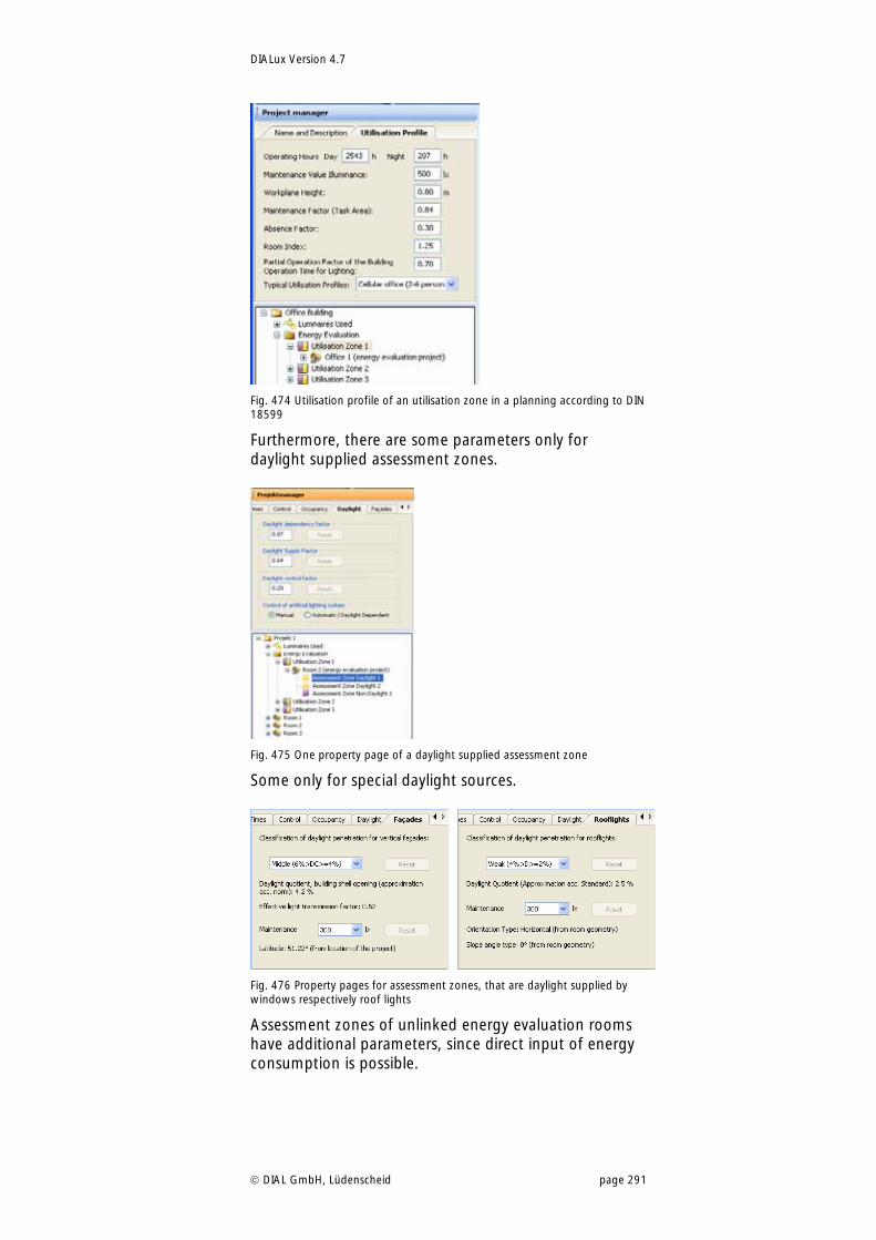
DIALux Version 4.7
DIAL GmbH, Lüdenscheid page 291
Fig. 474 Utilisation profile of an utilisation zone in a planning according to DIN 18599
Furthermore, there are some parameters only for daylight supplied assessment zones.
Fig. 475 One property page of a daylight supplied assessment zone
Some only for special daylight sources.
Fig. 476 Property pages for assessment zones, that are daylight supplied by windows respectively roof lights
Assessment zones of unlinked energy evaluation rooms have additional parameters, since direct input of energy consumption is possible.
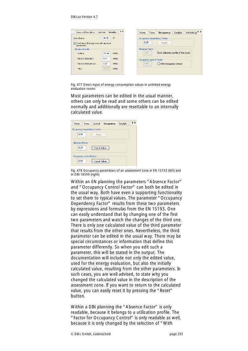
DIALux Version 4.7
DIAL GmbH, Lüdenscheid page 292
Fig. 477 Direct input of energy consumption values in unlinked energy evaluation rooms
Most parameters can be edited in the usual manner, others can only be read and some others can be edited normally and additionally are resettable to an internally calculated value.
Fig. 478 Occupancy parameters of an assessment zone in EN 15193 (left) and in DIN 18599 (right)
Within an EN planning the parameters “Absence Factor” and “Occupancy Control Factor” can both be edited in the usual way. Both have even a supporting functionality to set them to typical values. The parameter “Occupancy Dependency Factor” results from these two parameters by expressions and formulas from the EN 15193. One can easily understand that by changing one of the first two parameters and watch the changes of the third one. There is only one calculated value of the third parameter that results from the other ones. Nevertheless, the third parameter can be edited in the usual way. There may be special circumstances or information that define this parameter differently. So when you edit such a parameter, this will be stated in the output. The documentation will include not only the edited value, used for the energy evaluation, but also the initially calculated value, resulting from the other parameters. In such cases, you are well advised, to state why you changed the calculated value in the description of the assessment zone. If you want to return to the calculated value, you can easily reset it by pressing the “Reset” button. Within a DIN planning the “Absence Factor” is only readable, because it belongs to a utilization profile. The “Factor for Occupancy Control” is only readable as well, because it is only changed by the selection of “With
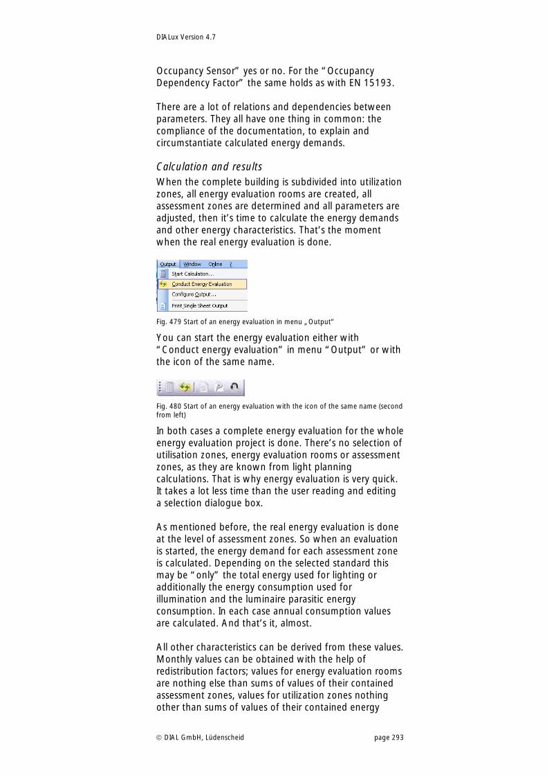
DIALux Version 4.7
DIAL GmbH, Lüdenscheid page 293
Occupancy Sensor” yes or no. For the “Occupancy Dependency Factor” the same holds as with EN 15193. There are a lot of relations and dependencies between parameters. They all have one thing in common: the compliance of the documentation, to explain and circumstantiate calculated energy demands.
Calculation and results When the complete building is subdivided into utilization zones, all energy evaluation rooms are created, all assessment zones are determined and all parameters are adjusted, then it’s time to calculate the energy demands and other energy characteristics. That’s the moment when the real energy evaluation is done.
Fig. 479 Start of an energy evaluation in menu „Output“
You can start the energy evaluation either with “Conduct energy evaluation” in menu “Output” or with the icon of the same name.
Fig. 480 Start of an energy evaluation with the icon of the same name (second from left)
In both cases a complete energy evaluation for the whole energy evaluation project is done. There’s no selection of utilisation zones, energy evaluation rooms or assessment zones, as they are known from light planning calculations. That is why energy evaluation is very quick. It takes a lot less time than the user reading and editing a selection dialogue box. As mentioned before, the real energy evaluation is done at the level of assessment zones. So when an evaluation is started, the energy demand for each assessment zone is calculated. Depending on the selected standard this may be “only” the total energy used for lighting or additionally the energy consumption used for illumination and the luminaire parasitic energy consumption. In each case annual consumption values are calculated. And that’s it, almost. All other characteristics can be derived from these values. Monthly values can be obtained with the help of redistribution factors; values for energy evaluation rooms are nothing else than sums of values of their contained assessment zones, values for utilization zones nothing other than sums of values of their contained energy
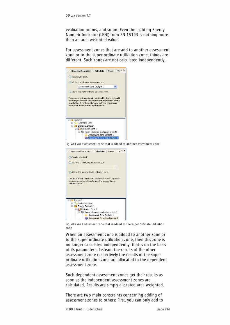
DIALux Version 4.7
DIAL GmbH, Lüdenscheid page 294
evaluation rooms, and so on. Even the Lighting Energy Numeric Indicator (LENI) from EN 15193 is nothing more than an area weighted value. For assessment zones that are add to another assessment zone or to the super ordinate utilization zone, things are different. Such zones are not calculated independently.
Fig. 481 An assessment zone that is added to another assessment zone
Fig. 482 An assessment zone that is added to the super ordinate utilisation zone
When an assessment zone is added to another zone or to the super ordinate utilization zone, then this zone is no longer calculated independently, that is on the basis of its parameters. Instead, the results of the other assessment zone respectively the results of the super ordinate utilization zone are allocated to the dependent assessment zone. Such dependent assessment zones get their results as soon as the independent assessment zones are calculated. Results are simply allocated area weighted. There are two main constraints concerning adding of assessment zones to others: First, you can only add to
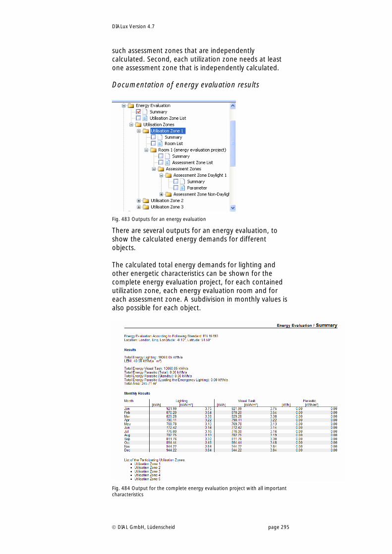
DIALux Version 4.7
DIAL GmbH, Lüdenscheid page 295
such assessment zones that are independently calculated. Second, each utilization zone needs at least one assessment zone that is independently calculated.
Documentation of energy evaluation results
Fig. 483 Outputs for an energy evaluation
There are several outputs for an energy evaluation, to show the calculated energy demands for different objects. The calculated total energy demands for lighting and other energetic characteristics can be shown for the complete energy evaluation project, for each contained utilization zone, each energy evaluation room and for each assessment zone. A subdivision in monthly values is also possible for each object.
Fig. 484 Output for the complete energy evaluation project with all important characteristics
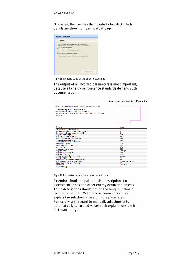
DIALux Version 4.7
DIAL GmbH, Lüdenscheid page 296
Of course, the user has the possibility to select which details are shown on each output page.
Fig. 485 Property page of the above output page
The output of all involved parameters is most important, because all energy performance standards demand such documentations.
Fig. 486 Parameter output for an assessment zone
Attention should be paid to using descriptions for assessment zones and other energy evaluation objects. These descriptions should not be too long, but should frequently be used. With precise comments you can explain the selection of one or more parameters. Particularly with regard to manually adjustments to automatically calculated values such explanations are in fact mandatory.
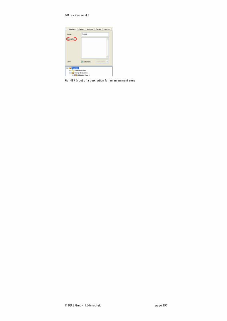
DIALux Version 4.7
DIAL GmbH, Lüdenscheid page 297
Fig. 487 Input of a description for an assessment zone
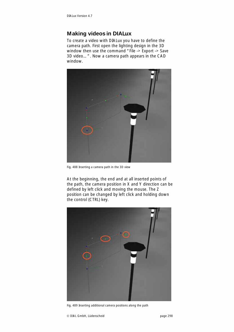
DIALux Version 4.7
DIAL GmbH, Lüdenscheid page 298
Making videos in DIALux To create a video with DIALux you have to define the camera path. First open the lighting design in the 3D window then use the command “File -> Export -> Save 3D video…”. Now a camera path appears in the CAD window.
Fig. 488 Inserting a camera path in the 3D view
At the beginning, the end and at all inserted points of the path, the camera position in X and Y direction can be defined by left click and moving the mouse. The Z position can be changed by left click and holding down the control (CTRL) key.
Fig. 489 Inserting additional camera positions along the path
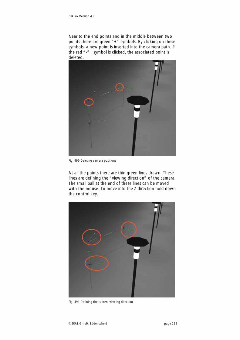
DIALux Version 4.7
DIAL GmbH, Lüdenscheid page 299
Near to the end points and in the middle between two points there are green “+” symbols. By clicking on these symbols, a new point is inserted into the camera path. If the red “-” symbol is clicked, the associated point is deleted.
Fig. 490 Deleting camera positions
At all the points there are thin green lines drawn. These lines are defining the “viewing direction” of the camera. The small ball at the end of these lines can be moved with the mouse. To move into the Z direction hold down the control key.
Fig. 491 Defining the camera viewing direction
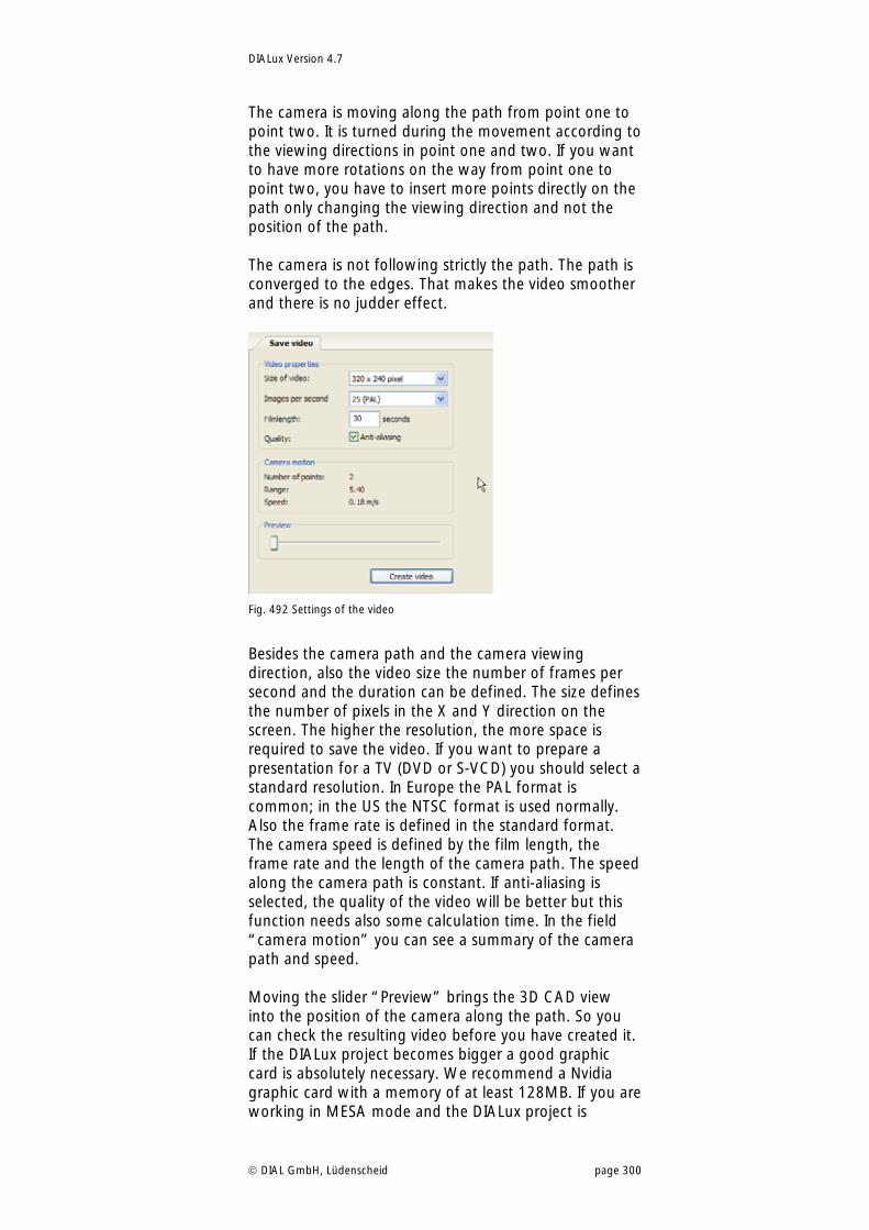
DIALux Version 4.7
DIAL GmbH, Lüdenscheid page 300
The camera is moving along the path from point one to point two. It is turned during the movement according to the viewing directions in point one and two. If you want to have more rotations on the way from point one to point two, you have to insert more points directly on the path only changing the viewing direction and not the position of the path. The camera is not following strictly the path. The path is converged to the edges. That makes the video smoother and there is no judder effect.
Fig. 492 Settings of the video
Besides the camera path and the camera viewing direction, also the video size the number of frames per second and the duration can be defined. The size defines the number of pixels in the X and Y direction on the screen. The higher the resolution, the more space is required to save the video. If you want to prepare a presentation for a TV (DVD or S-VCD) you should select a standard resolution. In Europe the PAL format is common; in the US the NTSC format is used normally. Also the frame rate is defined in the standard format. The camera speed is defined by the film length, the frame rate and the length of the camera path. The speed along the camera path is constant. If anti-aliasing is selected, the quality of the video will be better but this function needs also some calculation time. In the field “camera motion” you can see a summary of the camera path and speed. Moving the slider “Preview” brings the 3D CAD view into the position of the camera along the path. So you can check the resulting video before you have created it. If the DIALux project becomes bigger a good graphic card is absolutely necessary. We recommend a Nvidia graphic card with a memory of at least 128MB. If you are working in MESA mode and the DIALux project is
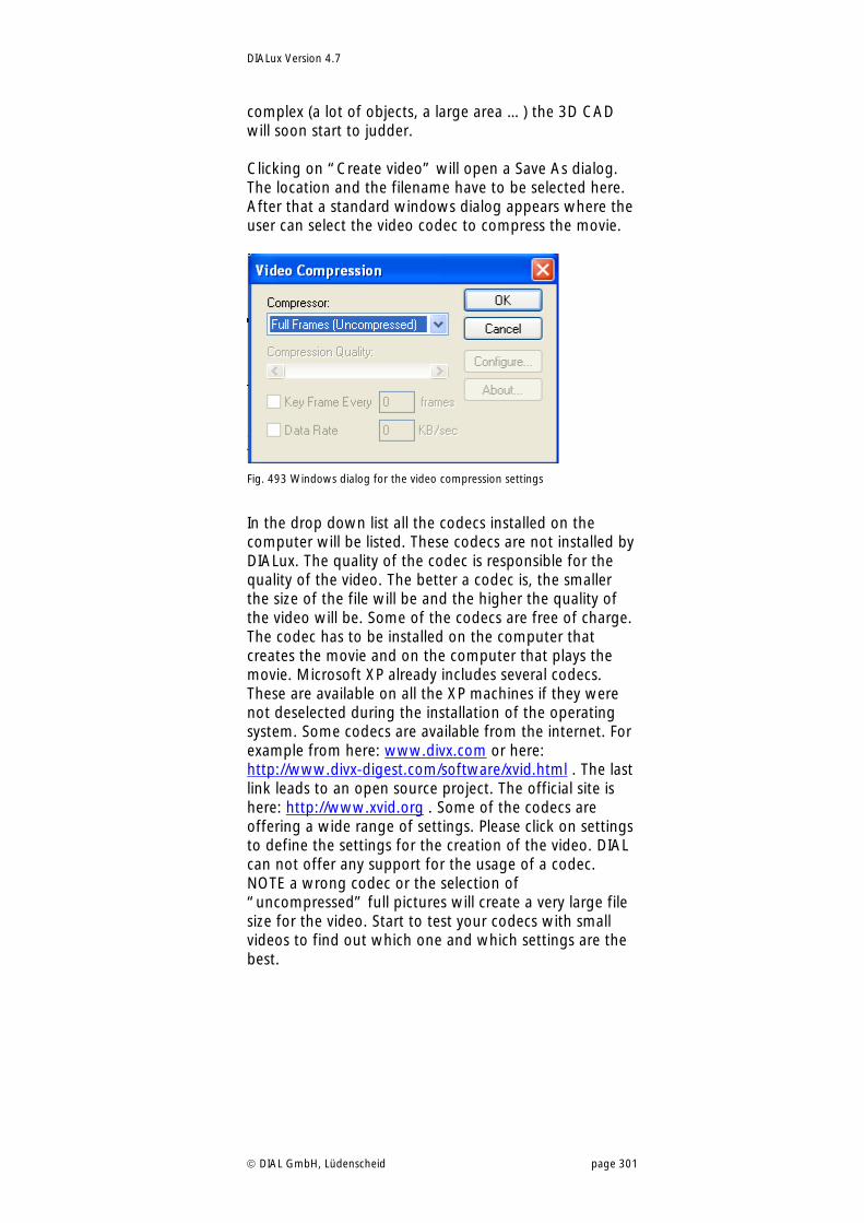
DIALux Version 4.7
DIAL GmbH, Lüdenscheid page 301
complex (a lot of objects, a large area …) the 3D CAD will soon start to judder. Clicking on “Create video” will open a Save As dialog. The location and the filename have to be selected here. After that a standard windows dialog appears where the user can select the video codec to compress the movie.
Fig. 493 Windows dialog for the video compression settings
In the drop down list all the codecs installed on the computer will be listed. These codecs are not installed by DIALux. The quality of the codec is responsible for the quality of the video. The better a codec is, the smaller the size of the file will be and the higher the quality of the video will be. Some of the codecs are free of charge. The codec has to be installed on the computer that creates the movie and on the computer that plays the movie. Microsoft XP already includes several codecs. These are available on all the XP machines if they were not deselected during the installation of the operating system. Some codecs are available from the internet. For example from here: www.divx.com or here: http://www.divx-digest.com/software/xvid.html . The last link leads to an open source project. The official site is here: http://www.xvid.org . Some of the codecs are offering a wide range of settings. Please click on settings to define the settings for the creation of the video. DIAL can not offer any support for the usage of a codec. NOTE a wrong codec or the selection of “uncompressed” full pictures will create a very large file size for the video. Start to test your codecs with small videos to find out which one and which settings are the best.
DIALux Version 4.7
DIAL GmbH, Lüdenscheid page 302
Raytracer For raytracing DIALux uses the external programme POV-Ray. If you want to have more detailed information about POV-Ray and the possible settings you can use the “F1”-key to open the POV-Ray help.
Background DIALux automatically copies POV-Ray onto the PC. The software will be installed when the user for the first time starts to calculate a photorealistic image. The setup installs the standard version of POV-Ray 3.6. This software is freeware and available at www.povray.org. Additionally DIALux installs an adapted version of the povengine.exe into the DIALux directory. The major difference between the DIALux version and the original version of POV-Ray is that the DIALux version can handle real photometry of luminaires. The measured light distribution of a luminaire is used to define the distribution of light. The original version can only handle ideal light sources like spot and ambient light. Whenever the DIALux user wants to edit the POV-Ray files, it is important to use the pvengine.exe in the DIALux directory e.g. “C:\Program Files\DIALux\pvengine.exe”. Otherwise the *.pov file can not be interpreted. You can continue to work with POV-Ray to edit the scene generated with DIALux. All functions of POV-Ray are available. For further editing you must use the program “pvengine.exe” that is stored in the directory “C:\Programs Files\DIALux\”. You cannot use the original POV-Ray software.
POV-Ray Settings within DIALux The most important settings for the raytracing with POV-Ray can be made in DIALux. For the standard use of the photorealistic visualisation these settings are adequate. Expert users can use all the features of POV-Ray by loading the *.pov file made with DIALux into the editor of POV-Ray.
Photo Realistic Images with Raytracing Raytracing means that the light beams from your own point of view with respect to mirroring, transparency and roughness of surfaces are followed.
Basic Settings The newest version of the Raytracer POV-Ray (3.6) is integrated in DIALux. This is substantially quicker and can choose the right brightness settings independently. For the visualizations with POV-Ray the spectral distributions of the lamps and the colour filter as well as the dimming level for the control groups are handed over
Important: You can open the separate POV-Ray help with “F1” while POV-Ray is running.
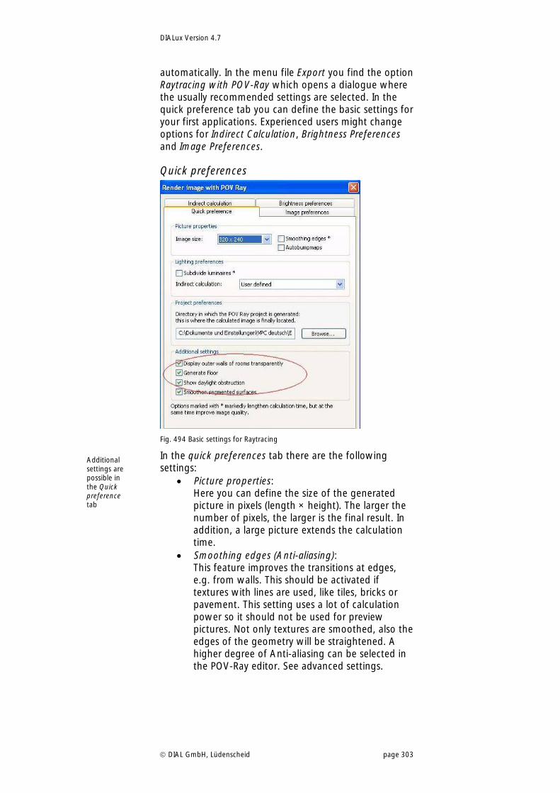
DIALux Version 4.7
DIAL GmbH, Lüdenscheid page 303
automatically. In the menu file Export you find the option Raytracing with POV-Ray which opens a dialogue where the usually recommended settings are selected. In the quick preference tab you can define the basic settings for your first applications. Experienced users might change options for Indirect Calculation, Brightness Preferences and Image Preferences.
Quick preferences
Fig. 494 Basic settings for Raytracing
In the quick preferences tab there are the following settings:
Picture properties: Here you can define the size of the generated picture in pixels (length × height). The larger the number of pixels, the larger is the final result. In addition, a large picture extends the calculation time.
Smoothing edges (Anti-aliasing): This feature improves the transitions at edges, e.g. from walls. This should be activated if textures with lines are used, like tiles, bricks or pavement. This setting uses a lot of calculation power so it should not be used for preview pictures. Not only textures are smoothed, also the edges of the geometry will be straightened. A higher degree of Anti-aliasing can be selected in the POV-Ray editor. See advanced settings.
Additional settings are possible in the Quick preference tab
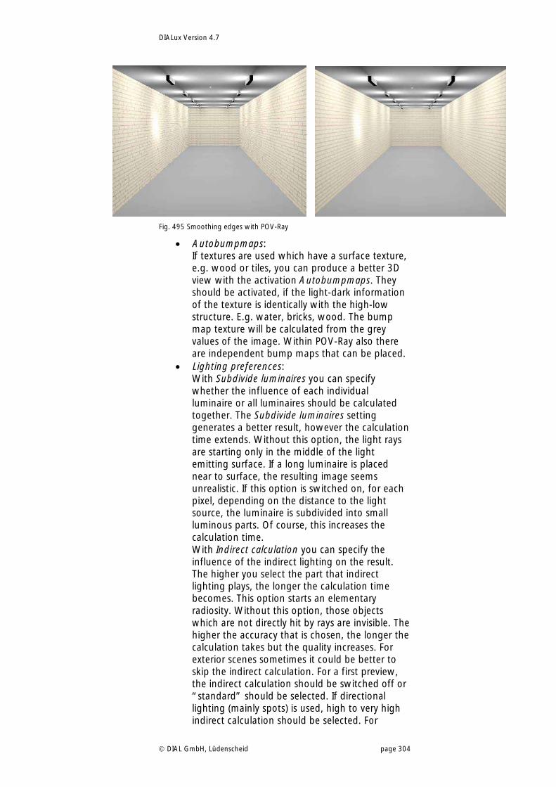
DIALux Version 4.7
DIAL GmbH, Lüdenscheid page 304
Fig. 495 Smoothing edges with POV-Ray
Autobumpmaps: If textures are used which have a surface texture, e.g. wood or tiles, you can produce a better 3D view with the activation Autobumpmaps. They should be activated, if the light-dark information of the texture is identically with the high-low structure. E.g. water, bricks, wood. The bump map texture will be calculated from the grey values of the image. Within POV-Ray also there are independent bump maps that can be placed.
Lighting preferences: With Subdivide luminaires you can specify whether the influence of each individual luminaire or all luminaires should be calculated together. The Subdivide luminaires setting generates a better result, however the calculation time extends. Without this option, the light rays are starting only in the middle of the light emitting surface. If a long luminaire is placed near to surface, the resulting image seems unrealistic. If this option is switched on, for each pixel, depending on the distance to the light source, the luminaire is subdivided into small luminous parts. Of course, this increases the calculation time. With Indirect calculation you can specify the influence of the indirect lighting on the result. The higher you select the part that indirect lighting plays, the longer the calculation time becomes. This option starts an elementary radiosity. Without this option, those objects which are not directly hit by rays are invisible. The higher the accuracy that is chosen, the longer the calculation takes but the quality increases. For exterior scenes sometimes it could be better to skip the indirect calculation. For a first preview, the indirect calculation should be switched off or “standard” should be selected. If directional lighting (mainly spots) is used, high to very high indirect calculation should be selected. For
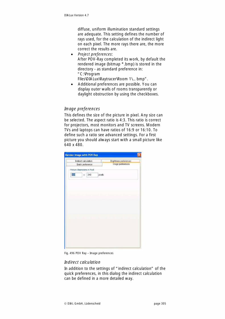
DIALux Version 4.7
DIAL GmbH, Lüdenscheid page 305
diffuse, uniform illumination standard settings are adequate. This setting defines the number of rays used, for the calculation of the indirect light on each pixel. The more rays there are, the more correct the results are.
Project preferences: After POV-Ray completed its work, by default the rendered image (bitmap *.bmp) is stored in the directory - as standard preference in: “C:\Program Files\DIALux\Raytracer\Room 1\…bmp”.
Additional preferences are possible. You can display outer walls of rooms transparently or daylight obstruction by using the checkboxes.
Image preferences This defines the size of the picture in pixel. Any size can be selected. The aspect ratio is 4:3. This ratio is correct for projectors, most monitors and TV screens. Modern TVs and laptops can have ratios of 16:9 or 16:10. To define such a ratio see advanced settings. For a first picture you should always start with a small picture like 640 x 480.
Fig. 496 POV Ray – Image preferences
Indirect calculation In addition to the settings of “indirect calculation” of the quick preferences, in this dialog the indirect calculation can be defined in a more detailed way.
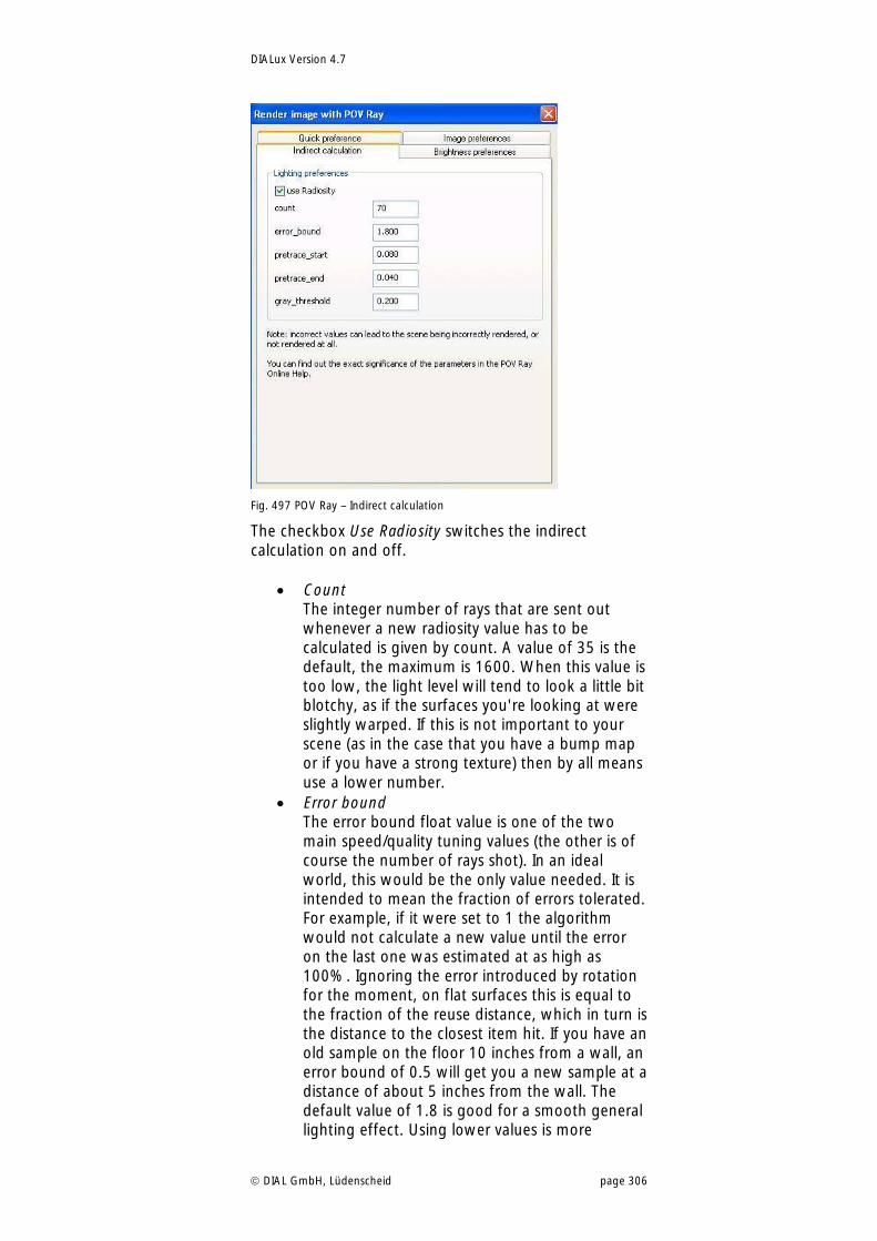
DIALux Version 4.7
DIAL GmbH, Lüdenscheid page 306
Fig. 497 POV Ray – Indirect calculation
The checkbox Use Radiosity switches the indirect calculation on and off.
Count The integer number of rays that are sent out whenever a new radiosity value has to be calculated is given by count. A value of 35 is the default, the maximum is 1600. When this value is too low, the light level will tend to look a little bit blotchy, as if the surfaces you're looking at were slightly warped. If this is not important to your scene (as in the case that you have a bump map or if you have a strong texture) then by all means use a lower number.
Error bound The error bound float value is one of the two main speed/quality tuning values (the other is of course the number of rays shot). In an ideal world, this would be the only value needed. It is intended to mean the fraction of errors tolerated. For example, if it were set to 1 the algorithm would not calculate a new value until the error on the last one was estimated at as high as 100%. Ignoring the error introduced by rotation for the moment, on flat surfaces this is equal to the fraction of the reuse distance, which in turn is the distance to the closest item hit. If you have an old sample on the floor 10 inches from a wall, an error bound of 0.5 will get you a new sample at a distance of about 5 inches from the wall. The default value of 1.8 is good for a smooth general lighting effect. Using lower values is more
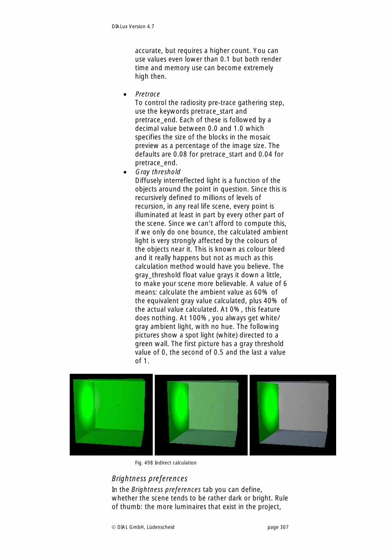
DIALux Version 4.7
DIAL GmbH, Lüdenscheid page 307
accurate, but requires a higher count. You can use values even lower than 0.1 but both render time and memory use can become extremely high then.
Pretrace To control the radiosity pre-trace gathering step, use the keywords pretrace_start and pretrace_end. Each of these is followed by a decimal value between 0.0 and 1.0 which specifies the size of the blocks in the mosaic preview as a percentage of the image size. The defaults are 0.08 for pretrace_start and 0.04 for pretrace_end.
Gray threshold Diffusely interreflected light is a function of the objects around the point in question. Since this is recursively defined to millions of levels of recursion, in any real life scene, every point is illuminated at least in part by every other part of the scene. Since we can't afford to compute this, if we only do one bounce, the calculated ambient light is very strongly affected by the colours of the objects near it. This is known as colour bleed and it really happens but not as much as this calculation method would have you believe. The gray_threshold float value grays it down a little, to make your scene more believable. A value of 6 means: calculate the ambient value as 60% of the equivalent gray value calculated, plus 40% of the actual value calculated. At 0%, this feature does nothing. At 100%, you always get white/ gray ambient light, with no hue. The following pictures show a spot light (white) directed to a green wall. The first picture has a gray threshold value of 0, the second of 0.5 and the last a value of 1.
Fig. 498 Indirect calculation
Brightness preferences In the Brightness preferences tab you can define, whether the scene tends to be rather dark or bright. Rule of thumb: the more luminaires that exist in the project,
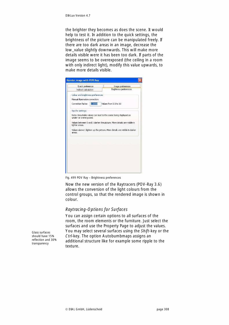
DIALux Version 4.7
DIAL GmbH, Lüdenscheid page 308
the brighter they becomes as does the scene. It would help to test it. In addition to the quick settings, the brightness of the picture can be manipulated freely. If there are too dark areas in an image, decrease the low_value slightly downwards. This will make more details visible were it has been too dark. If parts of the image seems to be overexposed (the ceiling in a room with only indirect light), modify this value upwards, to make more details visible.
Fig. 499 POV Ray – Brightness preferences
Now the new version of the Raytracers (POV-Ray 3.6) allows the conversion of the light colours from the control groups, so that the rendered image is shown in colour.
Raytracing-Options for Surfaces You can assign certain options to all surfaces of the room, the room elements or the furniture. Just select the surfaces and use the Property Page to adjust the values. You may select several surfaces using the Shift-key or the Ctrl-key. The option Autobumbmaps assigns an additional structure like for example some ripple to the texture.
Glass surfaces should have 15% reflection and 30% transparency
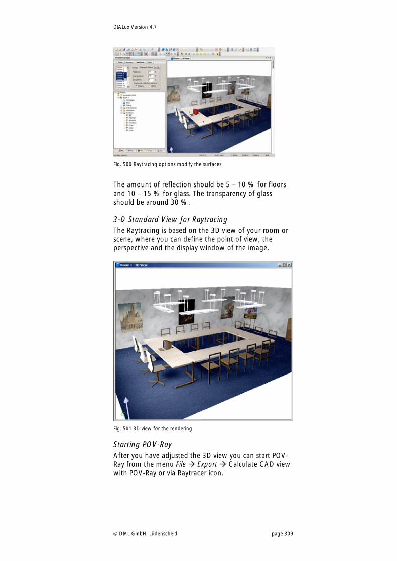
DIALux Version 4.7
DIAL GmbH, Lüdenscheid page 309
Fig. 500 Raytracing options modify the surfaces
The amount of reflection should be 5 – 10 % for floors and 10 – 15 % for glass. The transparency of glass should be around 30 %.
3-D Standard View for Raytracing The Raytracing is based on the 3D view of your room or scene, where you can define the point of view, the perspective and the display window of the image.
Fig. 501 3D view for the rendering
Starting POV-Ray After you have adjusted the 3D view you can start POV-Ray from the menu File Export Calculate CAD view with POV-Ray or via Raytracer icon.
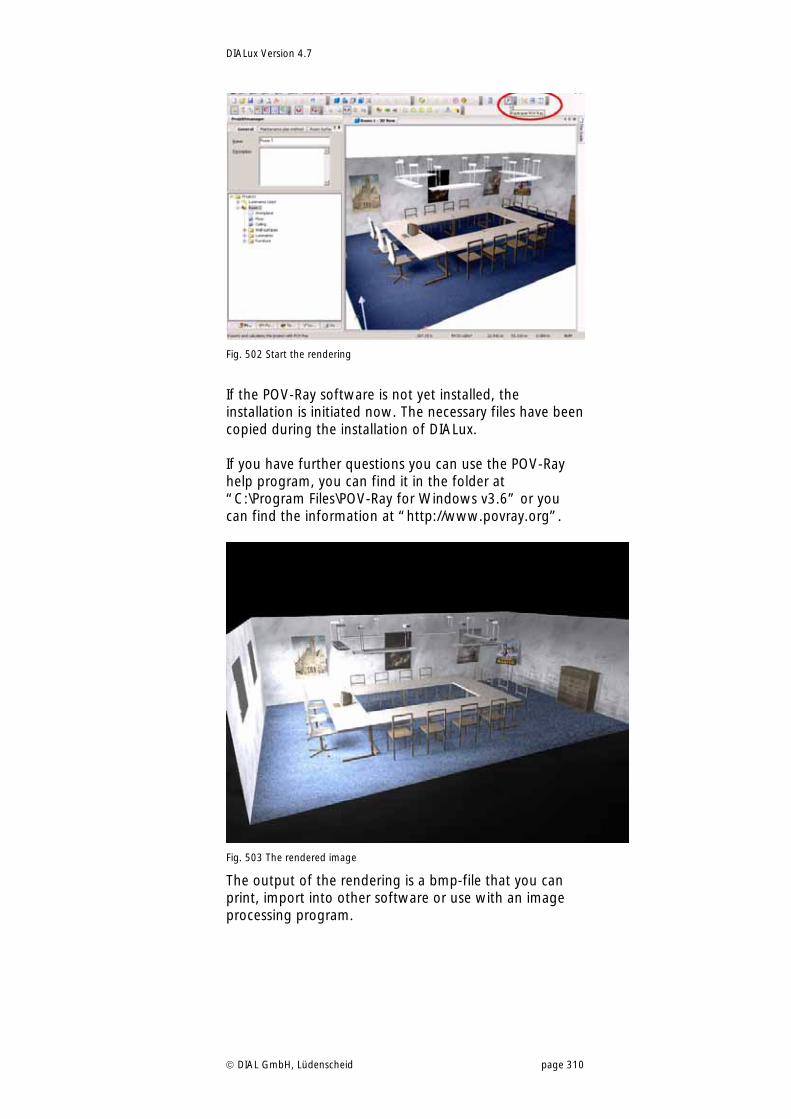
DIALux Version 4.7
DIAL GmbH, Lüdenscheid page 310
Fig. 502 Start the rendering
If the POV-Ray software is not yet installed, the installation is initiated now. The necessary files have been copied during the installation of DIALux. If you have further questions you can use the POV-Ray help program, you can find it in the folder at “C:\Program Files\POV-Ray for Windows v3.6” or you can find the information at “http://www.povray.org”.
Fig. 503 The rendered image
The output of the rendering is a bmp-file that you can print, import into other software or use with an image processing program.
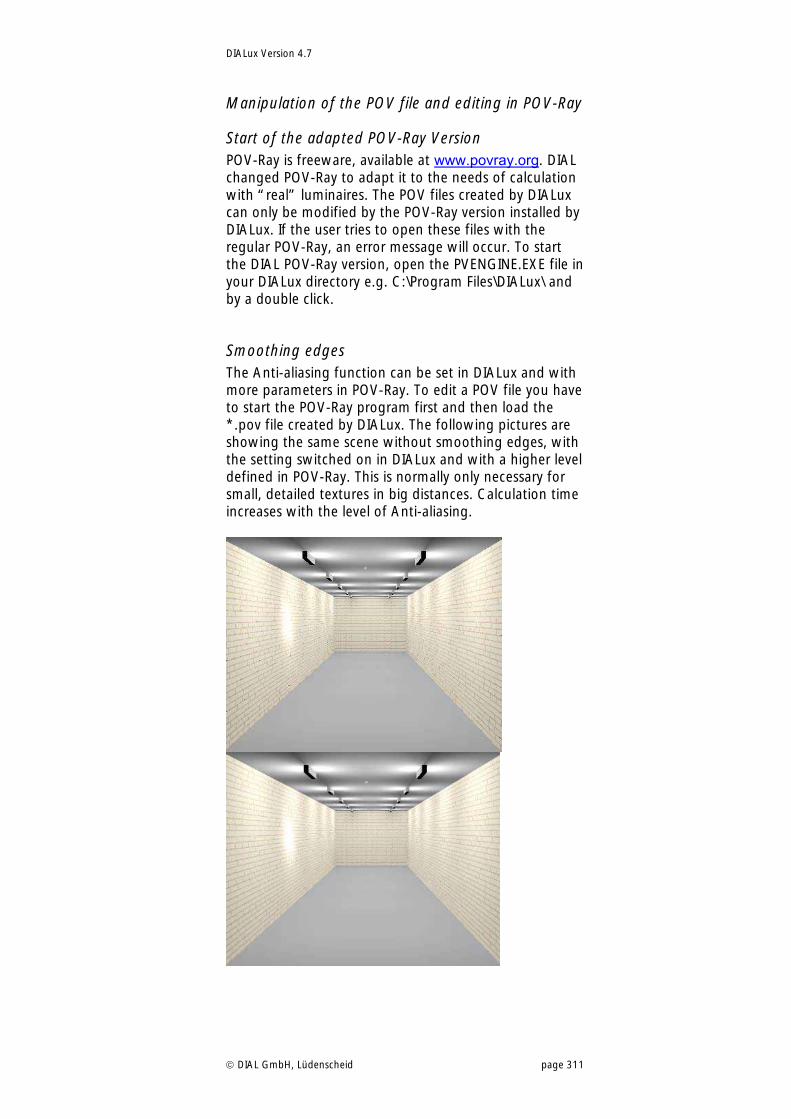
DIALux Version 4.7
DIAL GmbH, Lüdenscheid page 311
Manipulation of the POV file and editing in POV-Ray
Start of the adapted POV-Ray Version POV-Ray is freeware, available at www.povray.org. DIAL changed POV-Ray to adapt it to the needs of calculation with “real” luminaires. The POV files created by DIALux can only be modified by the POV-Ray version installed by DIALux. If the user tries to open these files with the regular POV-Ray, an error message will occur. To start the DIAL POV-Ray version, open the PVENGINE.EXE file in your DIALux directory e.g. C:\Program Files\DIALux\ and by a double click.
Smoothing edges The Anti-aliasing function can be set in DIALux and with more parameters in POV-Ray. To edit a POV file you have to start the POV-Ray program first and then load the *.pov file created by DIALux. The following pictures are showing the same scene without smoothing edges, with the setting switched on in DIALux and with a higher level defined in POV-Ray. This is normally only necessary for small, detailed textures in big distances. Calculation time increases with the level of Anti-aliasing.
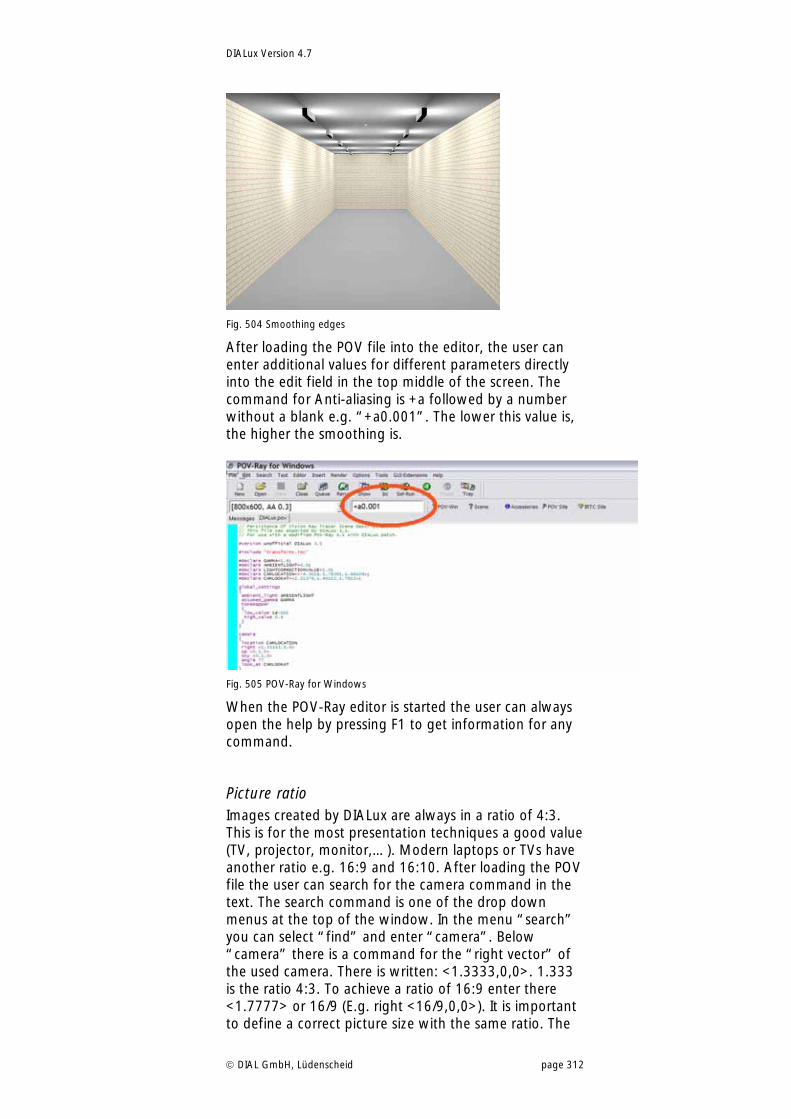
DIALux Version 4.7
DIAL GmbH, Lüdenscheid page 312
Fig. 504 Smoothing edges
After loading the POV file into the editor, the user can enter additional values for different parameters directly into the edit field in the top middle of the screen. The command for Anti-aliasing is +a followed by a number without a blank e.g. “+a0.001”. The lower this value is, the higher the smoothing is.
Fig. 505 POV-Ray for Windows
When the POV-Ray editor is started the user can always open the help by pressing F1 to get information for any command.
Picture ratio Images created by DIALux are always in a ratio of 4:3. This is for the most presentation techniques a good value (TV, projector, monitor,…). Modern laptops or TVs have another ratio e.g. 16:9 and 16:10. After loading the POV file the user can search for the camera command in the text. The search command is one of the drop down menus at the top of the window. In the menu “search” you can select “find” and enter “camera”. Below “camera” there is a command for the “right vector” of the used camera. There is written: <1.3333,0,0>. 1.333 is the ratio 4:3. To achieve a ratio of 16:9 enter there <1.7777> or 16/9 (E.g. right <16/9,0,0>). It is important to define a correct picture size with the same ratio. The
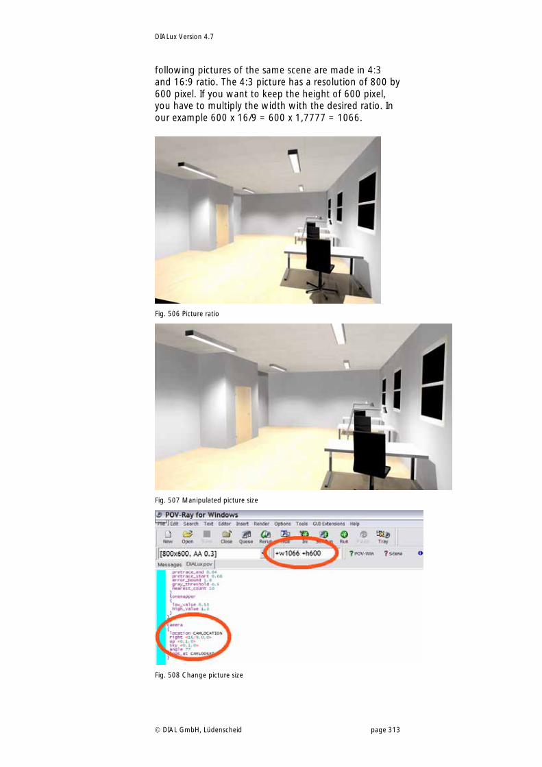
DIALux Version 4.7
DIAL GmbH, Lüdenscheid page 313
following pictures of the same scene are made in 4:3 and 16:9 ratio. The 4:3 picture has a resolution of 800 by 600 pixel. If you want to keep the height of 600 pixel, you have to multiply the width with the desired ratio. In our example 600 x 16/9 = 600 x 1,7777 = 1066.
Fig. 506 Picture ratio
Fig. 507 Manipulated picture size
Fig. 508 Change picture size
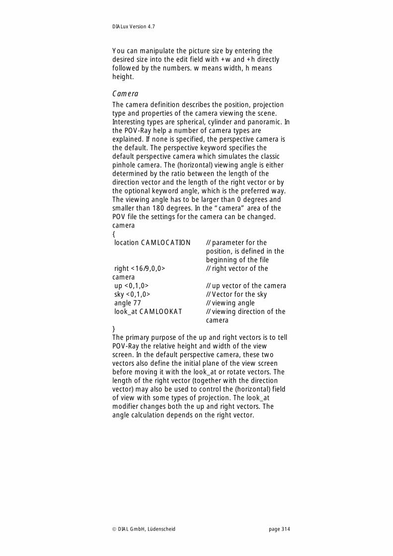
DIALux Version 4.7
DIAL GmbH, Lüdenscheid page 314
You can manipulate the picture size by entering the desired size into the edit field with +w and +h directly followed by the numbers. w means width, h means height.
Camera The camera definition describes the position, projection type and properties of the camera viewing the scene. Interesting types are spherical, cylinder and panoramic. In the POV-Ray help a number of camera types are explained. If none is specified, the perspective camera is the default. The perspective keyword specifies the default perspective camera which simulates the classic pinhole camera. The (horizontal) viewing angle is either determined by the ratio between the length of the direction vector and the length of the right vector or by the optional keyword angle, which is the preferred way. The viewing angle has to be larger than 0 degrees and smaller than 180 degrees. In the “camera” area of the POV file the settings for the camera can be changed. camera { location CAMLOCATION // parameter for the
position, is defined in the beginning of the file
right <16/9,0,0> // right vector of the camera up <0,1,0> // up vector of the camera sky <0,1,0> // Vector for the sky angle 77 // viewing angle look_at CAMLOOKAT // viewing direction of the
camera } The primary purpose of the up and right vectors is to tell POV-Ray the relative height and width of the view screen. In the default perspective camera, these two vectors also define the initial plane of the view screen before moving it with the look_at or rotate vectors. The length of the right vector (together with the direction vector) may also be used to control the (horizontal) field of view with some types of projection. The look_at modifier changes both the up and right vectors. The angle calculation depends on the right vector.
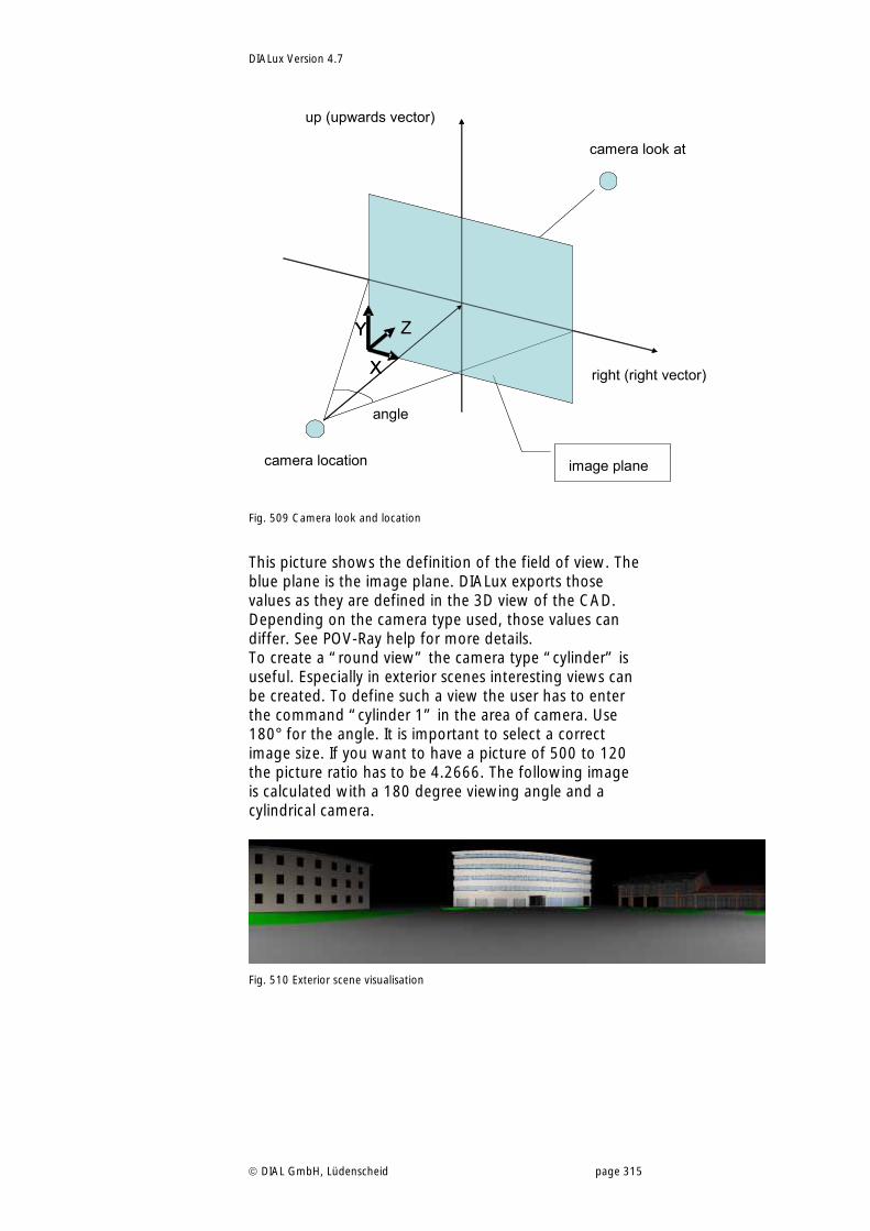
DIALux Version 4.7
DIAL GmbH, Lüdenscheid page 315
right (right vector)
up (upwards vector)
Y
X
Z
image plane
angle
camera location
camera look at
Y
X
Z
Fig. 509 Camera look and location
This picture shows the definition of the field of view. The blue plane is the image plane. DIALux exports those values as they are defined in the 3D view of the CAD. Depending on the camera type used, those values can differ. See POV-Ray help for more details. To create a “round view” the camera type “cylinder” is useful. Especially in exterior scenes interesting views can be created. To define such a view the user has to enter the command “cylinder 1” in the area of camera. Use 180° for the angle. It is important to select a correct image size. If you want to have a picture of 500 to 120 the picture ratio has to be 4.2666. The following image is calculated with a 180 degree viewing angle and a cylindrical camera.
Fig. 510 Exterior scene visualisation
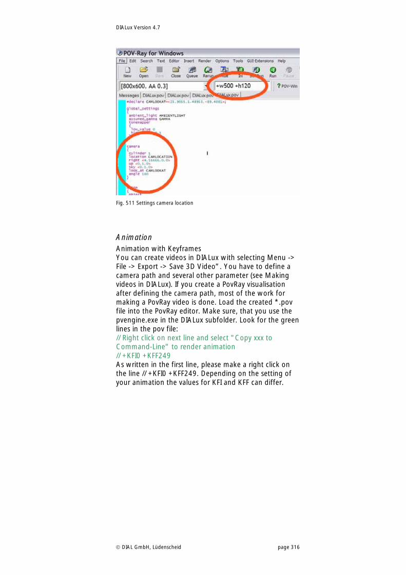
DIALux Version 4.7
DIAL GmbH, Lüdenscheid page 316
Fig. 511 Settings camera location
Animation Animation with Keyframes You can create videos in DIALux with selecting Menu -> File -> Export -> Save 3D Video”. You have to define a camera path and several other parameter (see Making videos in DIALux). If you create a PovRay visualisation after defining the camera path, most of the work for making a PovRay video is done. Load the created *.pov file into the PovRay editor. Make sure, that you use the pvengine.exe in the DIALux subfolder. Look for the green lines in the pov file: // Right click on next line and select "Copy xxx to Command-Line" to render animation // +KFI0 +KFF249 As written in the first line, please make a right click on the line // +KFI0 +KFF249. Depending on the setting of your animation the values for KFI and KFF can differ.
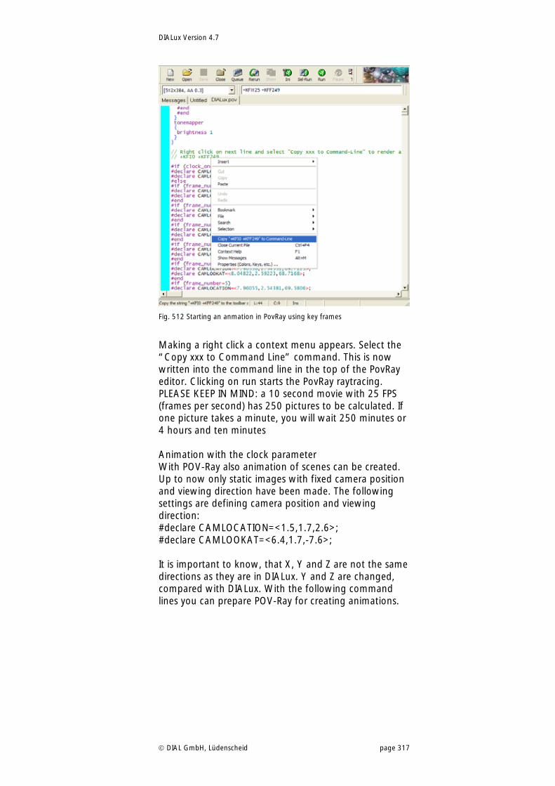
DIALux Version 4.7
DIAL GmbH, Lüdenscheid page 317
Fig. 512 Starting an anmation in PovRay using key frames
Making a right click a context menu appears. Select the “Copy xxx to Command Line” command. This is now written into the command line in the top of the PovRay editor. Clicking on run starts the PovRay raytracing. PLEASE KEEP IN MIND: a 10 second movie with 25 FPS (frames per second) has 250 pictures to be calculated. If one picture takes a minute, you will wait 250 minutes or 4 hours and ten minutes Animation with the clock parameter With POV-Ray also animation of scenes can be created. Up to now only static images with fixed camera position and viewing direction have been made. The following settings are defining camera position and viewing direction: #declare CAMLOCATION=<1.5,1.7,2.6>; #declare CAMLOOKAT=<6.4,1.7,-7.6>; It is important to know, that X, Y and Z are not the same directions as they are in DIALux. Y and Z are changed, compared with DIALux. With the following command lines you can prepare POV-Ray for creating animations.
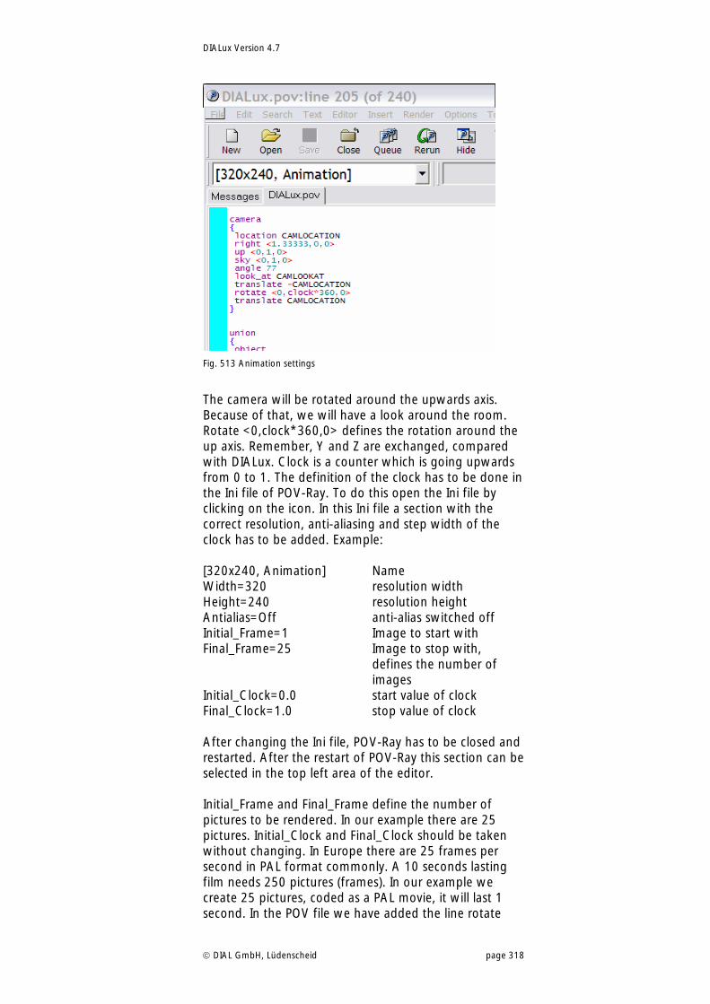
DIALux Version 4.7
DIAL GmbH, Lüdenscheid page 318
Fig. 513 Animation settings
The camera will be rotated around the upwards axis. Because of that, we will have a look around the room. Rotate <0,clock*360,0> defines the rotation around the up axis. Remember, Y and Z are exchanged, compared with DIALux. Clock is a counter which is going upwards from 0 to 1. The definition of the clock has to be done in the Ini file of POV-Ray. To do this open the Ini file by clicking on the icon. In this Ini file a section with the correct resolution, anti-aliasing and step width of the clock has to be added. Example: [320x240, Animation] Name Width=320 resolution width Height=240 resolution height Antialias=Off anti-alias switched off Initial_Frame=1 Image to start with Final_Frame=25 Image to stop with,
defines the number of images
Initial_Clock=0.0 start value of clock Final_Clock=1.0 stop value of clock After changing the Ini file, POV-Ray has to be closed and restarted. After the restart of POV-Ray this section can be selected in the top left area of the editor. Initial_Frame and Final_Frame define the number of pictures to be rendered. In our example there are 25 pictures. Initial_Clock and Final_Clock should be taken without changing. In Europe there are 25 frames per second in PAL format commonly. A 10 seconds lasting film needs 250 pictures (frames). In our example we create 25 pictures, coded as a PAL movie, it will last 1 second. In the POV file we have added the line rotate
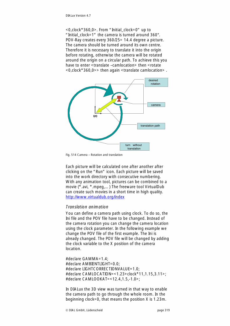
DIALux Version 4.7
DIAL GmbH, Lüdenscheid page 319
<0,clock*360,0>. From “Initial_clock=0” up to “Initial_clock=1” the camera is turned around 360°. POV-Ray creates every 360/25= 14.4 degree a picture. The camera should be turned around its own centre. Therefore it is necessary to translate it into the origin before rotating, otherwise the camera will be rotated around the origin on a circular path. To achieve this you have to enter <translate –camlocation> then <rotate <0,clock*360,0>> then again <translate camlocation> .
0/0
Kamera
gewünschte Drehung
Drehung ohneTranslation
Translationsweg
0/0
camera
desiredrotation
turn withouttranslation
translation path
Fig. 514 Camera – Rotation and translation
Each picture will be calculated one after another after clicking on the “Run” icon. Each picture will be saved into the work directory with consecutive numbering. With any animation tool, pictures can be combined to a movie (*.avi, *.mpeg,…) The freeware tool VirtualDub can create such movies in a short time in high quality. http://www.virtualdub.org/index
Translation animation You can define a camera path using clock. To do so, the Ini file and the POV file have to be changed. Instead of the camera rotation you can change the camera location using the clock parameter. In the following example we change the POV file of the first example. The Ini is already changed. The POV file will be changed by adding the clock variable to the X position of the camera location. #declare GAMMA=1.4; #declare AMBIENTLIGHT=0.0; #declare LIGHTCORRECTIONVALUE=1.0; #declare CAMLOCATION=<1.23+clock*11,1.15,3.11>; #declare CAMLOOKAT=<12.4,1.5,-1.0>; In DIALux the 3D view was turned in that way to enable the camera path to go through the whole room. In the beginning clock=0, that means the position X is 1.23m.
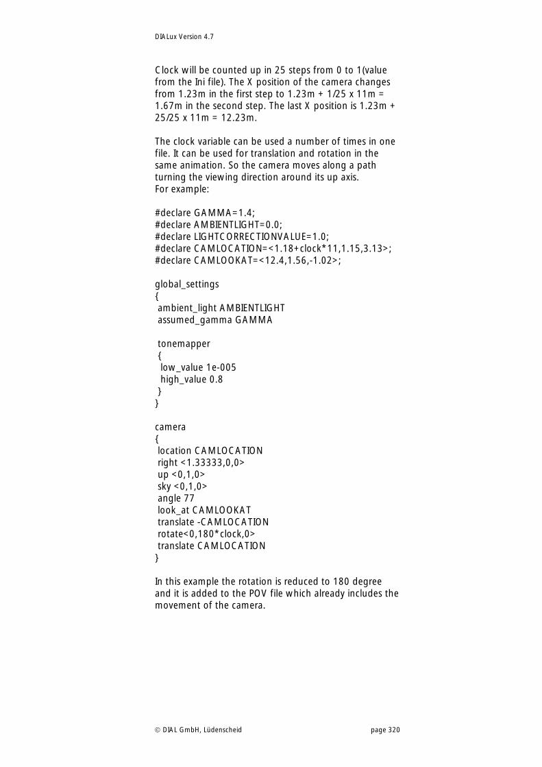
DIALux Version 4.7
DIAL GmbH, Lüdenscheid page 320
Clock will be counted up in 25 steps from 0 to 1(value from the Ini file). The X position of the camera changes from 1.23m in the first step to 1.23m + 1/25 x 11m = 1.67m in the second step. The last X position is 1.23m + 25/25 x 11m = 12.23m. The clock variable can be used a number of times in one file. It can be used for translation and rotation in the same animation. So the camera moves along a path turning the viewing direction around its up axis. For example: #declare GAMMA=1.4; #declare AMBIENTLIGHT=0.0; #declare LIGHTCORRECTIONVALUE=1.0; #declare CAMLOCATION=<1.18+clock*11,1.15,3.13>; #declare CAMLOOKAT=<12.4,1.56,-1.02>; global_settings { ambient_light AMBIENTLIGHT assumed_gamma GAMMA tonemapper { low_value 1e-005 high_value 0.8 } } camera { location CAMLOCATION right <1.33333,0,0> up <0,1,0> sky <0,1,0> angle 77 look_at CAMLOOKAT translate -CAMLOCATION rotate<0,180*clock,0> translate CAMLOCATION } In this example the rotation is reduced to 180 degree and it is added to the POV file which already includes the movement of the camera.
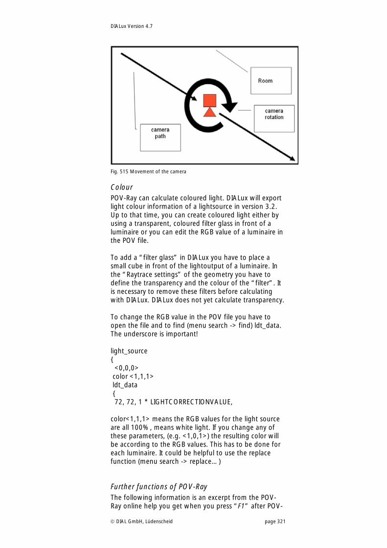
DIALux Version 4.7
DIAL GmbH, Lüdenscheid page 321
Fig. 515 Movement of the camera
Colour POV-Ray can calculate coloured light. DIALux will export light colour information of a lightsource in version 3.2. Up to that time, you can create coloured light either by using a transparent, coloured filter glass in front of a luminaire or you can edit the RGB value of a luminaire in the POV file. To add a “filter glass” in DIALux you have to place a small cube in front of the lightoutput of a luminaire. In the “Raytrace settings” of the geometry you have to define the transparency and the colour of the “filter”. It is necessary to remove these filters before calculating with DIALux. DIALux does not yet calculate transparency. To change the RGB value in the POV file you have to open the file and to find (menu search -> find) ldt_data. The underscore is important! light_source { <0,0,0> color <1,1,1> ldt_data { 72, 72, 1 * LIGHTCORRECTIONVALUE, color<1,1,1> means the RGB values for the light source are all 100%, means white light. If you change any of these parameters, (e.g. <1,0,1>) the resulting color will be according to the RGB values. This has to be done for each luminaire. It could be helpful to use the replace function (menu search -> replace…)
Further functions of POV-Ray The following information is an excerpt from the POV-Ray online help you get when you press “F1” after POV-
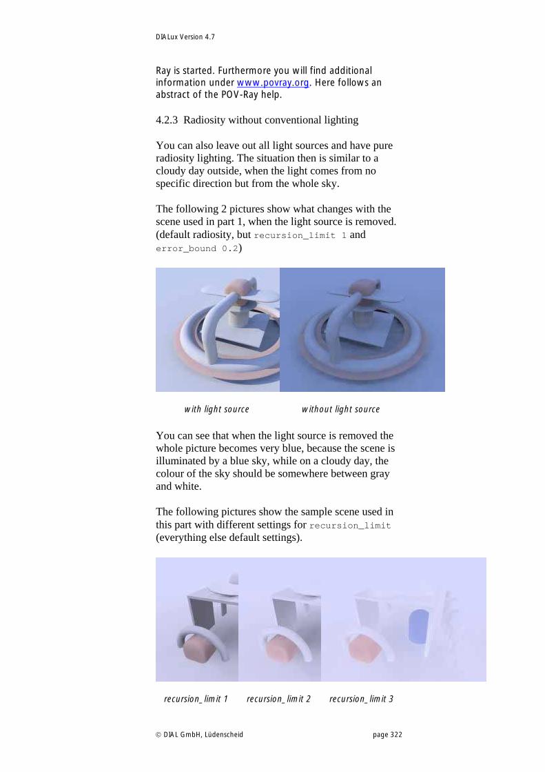
DIALux Version 4.7
DIAL GmbH, Lüdenscheid page 322
Ray is started. Furthermore you will find additional information under www.povray.org. Here follows an abstract of the POV-Ray help.
4.2.3 Radiosity without conventional lighting
You can also leave out all light sources and have pure radiosity lighting. The situation then is similar to a cloudy day outside, when the light comes from no specific direction but from the whole sky.
The following 2 pictures show what changes with the scene used in part 1, when the light source is removed. (default radiosity, but recursion_limit 1 and error_bound 0.2)
with light source
without light source
You can see that when the light source is removed the whole picture becomes very blue, because the scene is illuminated by a blue sky, while on a cloudy day, the colour of the sky should be somewhere between gray and white.
The following pictures show the sample scene used in this part with different settings for recursion_limit (everything else default settings).
recursion_limit 1
recursion_limit 2
recursion_limit 3
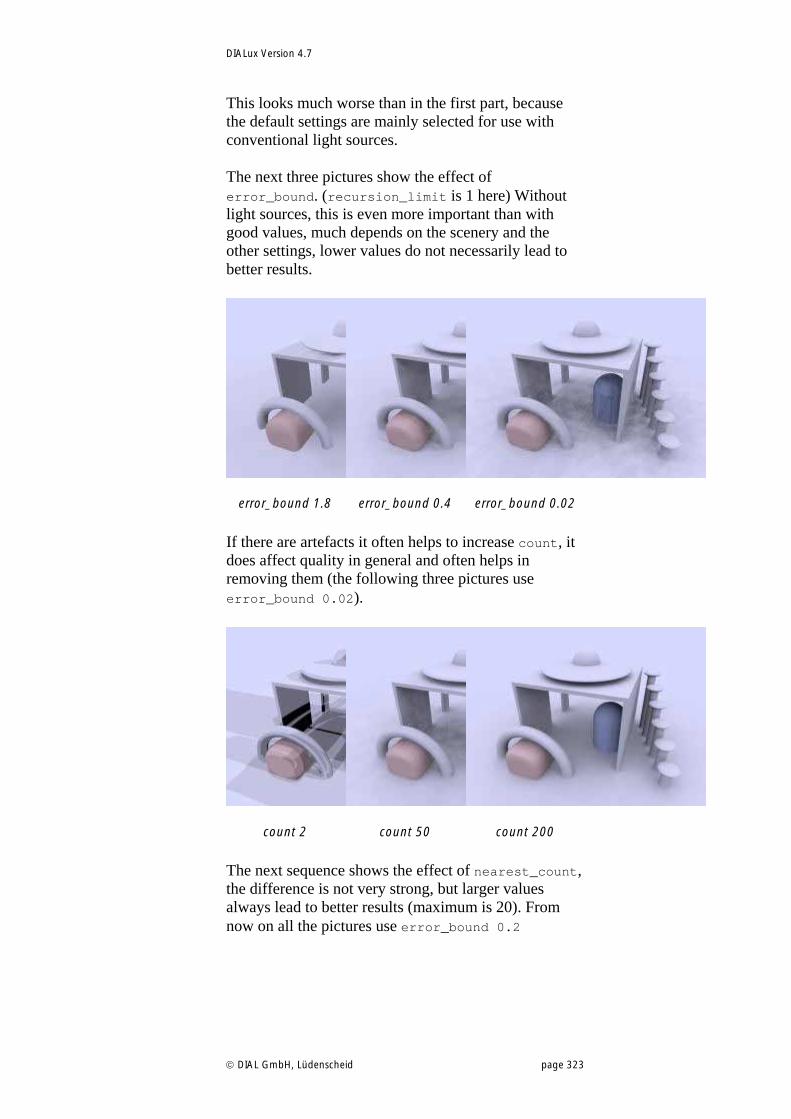
DIALux Version 4.7
DIAL GmbH, Lüdenscheid page 323
This looks much worse than in the first part, because the default settings are mainly selected for use with conventional light sources.
The next three pictures show the effect of error_bound. (recursion_limit is 1 here) Without light sources, this is even more important than with good values, much depends on the scenery and the other settings, lower values do not necessarily lead to better results.
error_bound 1.8
error_bound 0.4
error_bound 0.02
If there are artefacts it often helps to increase count, it does affect quality in general and often helps in removing them (the following three pictures use error_bound 0.02).
count 2
count 50
count 200
The next sequence shows the effect of nearest_count, the difference is not very strong, but larger values always lead to better results (maximum is 20). From now on all the pictures use error_bound 0.2
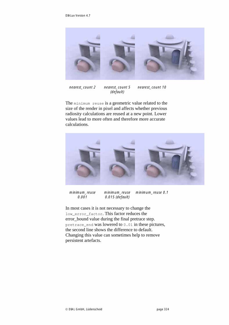
DIALux Version 4.7
DIAL GmbH, Lüdenscheid page 324
nearest_count 2
nearest_count 5
(default)
nearest_count 10
The minimum reuse is a geometric value related to the size of the render in pixel and affects whether previous radiosity calculations are reused at a new point. Lower values lead to more often and therefore more accurate calculations.
minimum_reuse
0.001
minimum_reuse 0.015 (default)
minimum_reuse 0.1
In most cases it is not necessary to change the low_error_factor. This factor reduces the error_bound value during the final pretrace step. pretrace_end was lowered to 0.01 in these pictures, the second line shows the difference to default. Changing this value can sometimes help to remove persistent artefacts.
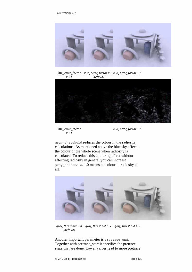
DIALux Version 4.7
DIAL GmbH, Lüdenscheid page 325
low_error_factor
0.01
low_error_factor 0.5
(default)
low_error_factor 1.0
low_error_factor
0.01
low_error_factor 1.0
gray_threshold reduces the colour in the radiosity calculations. As mentioned above the blue sky affects the colour of the whole scene when radiosity is calculated. To reduce this colouring effect without affecting radiosity in general you can increase gray_threshold. 1.0 means no colour in radiosity at all.
gray_threshold 0.0
(default)
gray_threshold 0.5
gray_threshold 1.0
Another important parameter is pretrace_end. Together with pretrace_start it specifies the pretrace steps that are done. Lower values lead to more pretrace
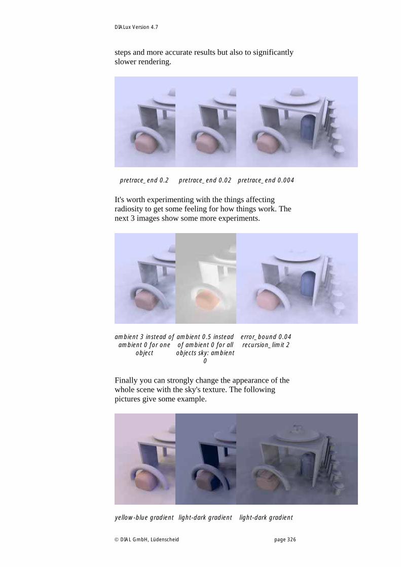
DIALux Version 4.7
DIAL GmbH, Lüdenscheid page 326
steps and more accurate results but also to significantly slower rendering.
pretrace_end 0.2
pretrace_end 0.02
pretrace_end 0.004
It's worth experimenting with the things affecting radiosity to get some feeling for how things work. The next 3 images show some more experiments.
ambient 3 instead of
ambient 0 for one object
ambient 0.5 instead of ambient 0 for all objects sky: ambient
0
error_bound 0.04 recursion_limit 2
Finally you can strongly change the appearance of the whole scene with the sky's texture. The following pictures give some example.
yellow-blue gradient
light-dark gradient
light-dark gradient
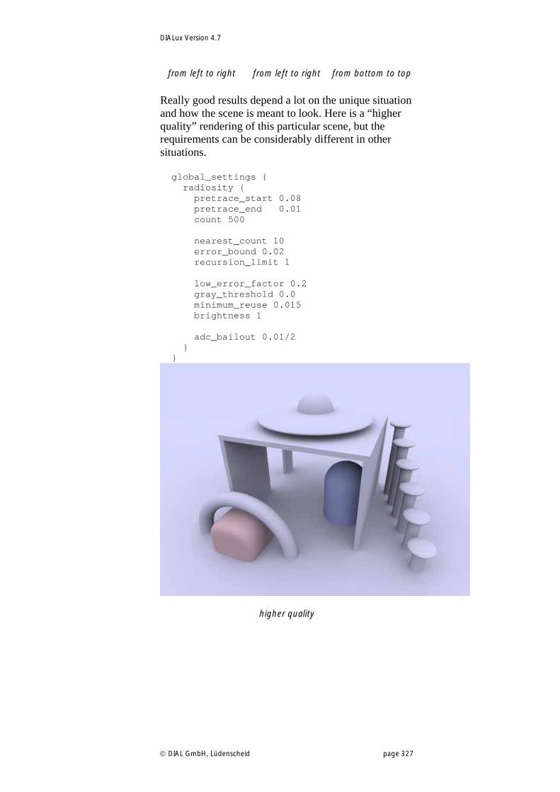
DIALux Version 4.7
DIAL GmbH, Lüdenscheid page 327
from left to right from left to right from bottom to top
Really good results depend a lot on the unique situation and how the scene is meant to look. Here is a “higher quality” rendering of this particular scene, but the requirements can be considerably different in other situations.
global_settings { radiosity { pretrace_start 0.08 pretrace_end 0.01 count 500 nearest_count 10 error_bound 0.02 recursion_limit 1 low_error_factor 0.2 gray_threshold 0.0 minimum_reuse 0.015 brightness 1 adc_bailout 0.01/2 } }
higher quality
DIALux Version 4.7
DIAL GmbH, Lüdenscheid page 328
List of figures Fig. 1 DIALux Setup.............................................................. 12 Fig. 2 Selection of the components to be installed ............... 13 Fig. 3 DIALux CD browser .................................................... 13 Fig. 4 DIALux online menu ................................................... 14 Fig. 5 Online update of luminaire catalogues ....................... 16 Fig. 6 DIALux Light Wizard – DIALux Light icon .................... 19 Fig. 7 DIALux Light Wizard – Start ........................................ 19 Fig. 8 DIALux Light Wizard – Project information.................. 20 Fig. 9 DIALux Light Wizard – Data Input............................... 20 Fig. 10 DIALux Light Wizard – Launch a PlugIn..................... 21 Fig. 11 DIALux Light Wizard – User Database ....................... 21 Fig. 12 DIALux Light Wizard – Calculation............................ 22 Fig. 13 DIALux Light Wizard – Calculated Result................... 22 Fig. 14 DIALux Light Wizard – Result Output........................ 23 Fig. 15 DIALux Light Wizard – Output .................................. 23 Fig. 16 DIALux Light Wizard – End ....................................... 24 Fig. 17 DIALux Startup Dialogue........................................... 25 Fig. 18 Launch DIALux Wizard.............................................. 25 Fig. 19 Working with Wizards – Start ................................... 26 Fig. 20 Working with Wizards – Room Name, Room Form,
Room Alignment ........................................... 27 Fig. 21 Working with Wizards – Room Dimensions .............. 27 Fig. 22 Working with Wizards – Reflection, Work plane,
Maintenance Factor....................................... 28 Fig. 23 Working with Wizards – Luminaire Manufacturer
Selection ....................................................... 29 Fig. 24 Working with Wizards – PlugIn / User Database........ 29 Fig. 25 Working with Wizards – Luminaire Selection ............ 30 Fig. 26 Working with Wizards – Mounting height ................ 30 Fig. 27 Working with Wizards – Calculate the number of
luminaires...................................................... 31 Fig. 28 Working with Wizards – Alignment of the luminaires31 Fig. 29 Working with Wizards – Calculate result .................. 32 Fig. 30 Working with Wizards – Visually represented result .. 32 Fig. 31 Working with Wizards – Single Sheet Output ........... 33 Fig. 32 DIALux user interface................................................ 34 Fig. 33 3D view of a room.................................................... 35 Fig. 34 Ground plan view of a room..................................... 35 Fig. 35 Right mouse button.................................................. 36 Fig. 36 3D CAD window context menu................................ 36 Fig. 37 Ground plan view context menu .............................. 36 Fig. 38 Context menu of a selected object ........................... 37 Fig. 39 Project manager ....................................................... 38 Fig. 40 PlugIn-Tree – Luminaire selection.............................. 39 Fig. 41 The User Database.................................................... 40 Fig. 42 Explorer context menu whilst DIALux 4.7 is running . 41 Fig. 43 Starting a lamp PlugIn in DIALux............................... 42 Fig. 44 DIALux lamp demo database .................................... 42 Fig. 45 The Furniture tree..................................................... 44 Fig. 46 The Colour tree ........................................................ 45 Fig. 47 Output Tab............................................................... 46 Fig. 48 Output tree .............................................................. 46 Fig. 49 Save a 3D rendering as .jpg file............................... 47 Fig. 50 The Guide ................................................................ 47 Fig. 51 Display guide window .............................................. 48 Fig. 52 Property Page of the selected room in the Inspector . 49
DIALux Version 4.7
DIAL GmbH, Lüdenscheid page 329
Fig. 53 Luminaire arrangement and its luminaires in the project manager........................................................ 49
Fig. 54 Property Page “Position” of the selected luminaire arrangement ................................................. 49
Fig. 55 Property Page of the luminaires within the selection. 50 Fig. 56 Room context menu (right-click on room)................. 51 Fig. 57 Room edit mode....................................................... 51 Fig. 58 Insert a new corner................................................... 52 Fig. 59 Edit a ground element .............................................. 52 Fig. 60 Create a polygonal "Task Area" above a desk .......... 53 Fig. 61 Taking over the shape of a helpline for the room
geometry....................................................... 53 Fig. 62 Menu Settings .......................................................... 54 Fig. 63 General Options – Standard Values .......................... 55 Fig. 64 General Options – Global ......................................... 55 Fig. 65 Automatic reminder to save data.............................. 56 Fig. 66 Start options............................................................. 56 Fig. 67 Graphic mode .......................................................... 57 Fig. 68 General Options – Output ........................................ 58 Fig. 69 General Options – Contact ....................................... 58 Fig. 70 Menu Customise ...................................................... 59 Fig. 71 Reset user interface .................................................. 59 Fig. 72 Create a new project ................................................ 60 Fig. 73 Insert project details ................................................. 60 Fig. 74 Insert Project data – Location.................................... 61 Fig. 75 Open a project in the startup dialogue ..................... 61 Fig. 76 Open a project in the menu...................................... 61 Fig. 77 Project preview......................................................... 62 Fig. 78 Edit Rooms – Generate a new room ......................... 63 Fig. 79 Edit Rooms – Insert room coordinates....................... 63 Fig. 80 Edit Rooms – Zoom to the overall view of the scene . 63 Fig. 81 Edit Rooms – 3D view............................................... 64 Fig. 82 Edit room data – General.......................................... 64 Fig. 83 Edit room data – Maintenance plan method............. 65 Fig. 84 Edit room data – Selection of a reference value for the
maintenance factor ....................................... 65 Fig. 85 Technical data of the placed luminaire...................... 66 Fig. 86 Determination of the luminaire number of pieces ..... 66 Fig. 87 Output – Maintenance plan...................................... 67 Fig. 88 Selection of the determination of the enlarged
maintenance factor ....................................... 68 Fig. 89 Technical settings of luminaires with different luminous
emittances..................................................... 68 Fig. 90 Determination of the number of required luminaires 69 Fig. 91 Property Page Maintenance factor............................ 70 Fig. 92 User-defined maintenance factors ............................ 71 Fig. 93 Insert another arrangement in the same room.......... 72 Fig. 94 Show maintenance factors in the CAD via menu ...... 72 Fig. 95 Icon “Show maintenance factors in the CAD”.......... 73 Fig. 96 Menu Edit – Edit Maintenance Factors...................... 73 Fig. 97 Context menu of the luminaire arrangement - Edit
Maintenance Factors ..................................... 73 Fig. 98 View of the maintenance factors of individual
luminaires in the CAD ................................... 74 Fig. 99 Export of the maintenance plan................................ 74 Fig. 100 Edit room data – Room surfaces ............................. 75 Fig. 101 Edit room data - Alignment .................................... 75 Fig. 102 Properties of a wall – Name.................................... 76 Fig. 103 Properties of a wall – Material ................................ 76 Fig. 104 Inserting a standard element .................................. 77
DIALux Version 4.7
DIAL GmbH, Lüdenscheid page 330
Fig. 105 Edit rooms – Insert room element........................... 78 Fig. 106 Edit rooms – Edit room element ............................. 79 Fig. 107 Edit rooms – DIALux room elements ....................... 79 Fig. 108 DIALux room elements – Vault ............................... 79 Fig. 109 DIALux room elements – Dome and half dome....... 80 Fig. 110 Edit rooms – Insert room elements via Property Page
..................................................................... 80 Fig. 111 Drag and Drop of furniture..................................... 81 Fig. 112 Create furniture – Standard bodies......................... 81 Fig. 113 Create furniture – Modify the dimensions............... 82 Fig. 114 Create furniture – Copy.......................................... 82 Fig. 115 Create furniture – Combine.................................... 83 Fig. 116 Create furniture – Export furniture ......................... 83 Fig. 117 Create furniture – Saved furniture .......................... 84 Fig. 118 Import furniture files............................................... 84 Fig. 119 Importing 3D wizard............................................... 85 Fig. 120 Creating an extrusion volume................................. 86 Fig. 121 Mask and unmask glass objects.............................. 86 Fig. 122 Examples for objects of glass (before and after using
the Ray-Trace preview) .................................. 87 Fig. 123 Subtractions from a volume.................................... 88 Fig. 124 Resulting volume .................................................... 88 Fig. 125 Selecting specific surfaces from a volume ............... 89 Fig. 126 Drag & drop for windows and doors ...................... 89 Fig. 127 Context menu – decoration object ......................... 90 Fig. 128 Decoration object in the project tree ...................... 91 Fig. 129 Calculation dialogue............................................... 91 Fig. 130 Insert textures via Drag & Drop............................... 92 Fig. 131 Edit textures on an object ....................................... 93 Fig. 132 Delete textures ....................................................... 93 Fig. 133 Import textures into DIALux.................................... 94 Fig. 134 Opening the material dialogue of a surface ............ 95 Fig. 135 Selection of the Raytrace preview ........................... 97 Fig. 136 Raytrace preview parameters .................................. 97 Fig. 137 Output of the Raytrace preview.............................. 98 Fig. 138 Duplicate rooms ..................................................... 99 Fig. 139 Launch luminaire tree ........................................... 100 Fig. 140 Launch online catalogues ..................................... 101 Fig. 141 Insert individual luminaires.................................... 102 Fig. 142 Luminaire selection dropdown list ........................ 102 Fig. 143 Mounting tab ....................................................... 103 Fig. 144 Modifying the technical data of luminaires ........... 103 Fig. 145 Help rays for luminaires ........................................ 104 Fig. 146 Luminaries with 3D LDC ....................................... 104 Fig. 147 Mouse mode to define illumination point ............. 105 Fig. 148 Selection of individual luminaires.......................... 105 Fig. 149 Align a spotlight to a picture ................................ 106 Fig. 150 Insert luminaire fields without wizard ................... 106 Fig. 151 Manipulating a luminaire within an arrangement . 107 Fig. 152 Selecting the arrangement type of a luminaire field
................................................................... 108 Fig. 153 Effect of arrangement type and dimensioning type on
the luminaire field dimensions ..................... 108 Fig. 154 Luminaire field insert frames depending on the
arrangement type........................................ 109 Fig. 155 Luminaires used in the arrangement..................... 109 Fig. 156 Rotating the arrangement and the luminaires....... 110 Fig. 157 Luminaire field position ........................................ 110 Fig. 158 Scale a luminaire line ............................................ 111 Fig. 159 Edit a luminaire line .............................................. 111
DIALux Version 4.7
DIAL GmbH, Lüdenscheid page 331
Fig. 160 Aligning individual luminaires within an arrangement................................................................... 112
Fig. 161 Selection filter for CAD selection .......................... 112 Fig. 162 Luminaire circle start and end angle ..................... 113 Fig. 163 Inserting floodlight illumination in a sports complex
................................................................... 114 Fig. 164 Settings options in the project manager ............... 114 Fig. 165 Mirroring options for floodlight illumination ......... 115 Fig. 166 Options for changing the illumination points ........ 116 Fig. 167 Moving an illumination point manually................. 116 Fig. 168 Cancelling the symmetry of floodlight illumination 116 Fig. 169 Individually adjustable luminaire positions after
cancelling the symmetry .............................. 117 Fig. 170 Transforming a single luminaire into an individual
arrangement. .............................................. 117 Fig. 171 Modify luminaire data – Corrections..................... 118 Fig. 172 Modify luminaire data – Mounting height ............ 118 Fig. 173 Selection of rotatable luminaire parts ................... 118 Fig. 174 Turn the rotatable luminaire part by mouse pointer
................................................................... 119 Fig. 175 Align the rotatable luminaire part......................... 119 Fig. 176 Symbol for luminaires with several articulated joints
................................................................... 119 Fig. 177 Context menu of the unrestricted luminaire
arrangement ............................................... 120 Fig. 178 Modify the new luminaire arrangement................ 120 Fig. 179 Remove from luminaire group .............................. 121 Fig. 180 Aligning luminaire arrangements – Context menu 121 Fig. 181 Set illumination point – Aligned luminaire field..... 122 Fig. 182 Selection of a direct planar lighting situation ........ 123 Fig. 183 Alternative solution to insert a direct planar lighting
situation ...................................................... 123 Fig. 184 Insertion of selected luminaries into the direct planar
lighting situation ......................................... 124 Fig. 185 Insertion of additional points to the lighting situation
................................................................... 124 Fig. 186 Changes in Mounting Height (1), Arrangement of
luminaries (2) and Rotations of single luminaries (3) at vertical planar lighting solutions ......... 125
Fig. 187 Editing the single axes – direct planar lighting ...... 125 Fig. 188 Selection of a vertical planar lighting situation...... 126 Fig. 189 Alternative solution to insert a vertical planar lighting
situation ...................................................... 126 Fig. 190 Insertion of selected luminaries into the vertical planar
lighting solution .......................................... 127 Fig. 191 Changes in Mounting Height (1), Arrangement of
luminaries (2) and Rotations of single luminaries (3) at vertical planar lighting solutions ......... 127
Fig. 192 Editing the single axes – vertical planar lighting .... 128 Fig. 193 Spectral light calculation....................................... 129 Fig. 194 Non spectral light calculation................................ 130 Fig. 195 Light colours in the DIALux colour tree ................. 131 Fig. 196 Colour information for a selected spectrum.......... 131 Fig. 197 Colour rendering indices of the CIE test colours (CIE
13.3) ........................................................... 132 Fig. 198 Spectra and colour rendering properties of different
light sources ................................................ 132 Fig. 199 Drag and Drop of a spectrum onto a luminaire with
rotatable elements....................................... 133
DIALux Version 4.7
DIAL GmbH, Lüdenscheid page 332
Fig. 200 Drag and drop of a filter / spectrum, while holding down the control key .................................. 134
Fig. 201 Drag and drop of a spectrum / filter on a rotatable element of a luminaire while holding down the shift key ...................................................... 134
Fig. 202 Spectrum of the lamp, the filter and the resulting radiation. Click on the triangle on the bottom right to get the Ra values. ........................... 135
Fig. 203 Technical information of colour filter .................... 136 Fig. 204 Resulting spectrum of a luminaire with two times the
same filter but different light sources .......... 136 Fig. 205 All the spots are using the same colour filter, but have
different light sources. From the left: Incandescent, Flourescent 830, D65, high pressure sodium, metal halide ceramic and metal halide quartz...................................... 137
Fig. 206 Four identical photos using different values for the white balance (Source: wikipedia, foto Thomas Steiner)........................................................ 137
Fig. 207 Adjusting the white balance ................................. 138 Fig. 208 Paste a control group via menu ............................ 140 Fig. 209 Paste a control group – Context menu of the room
................................................................... 140 Fig. 210 Paste a control group – Context menu in the CAD
view ............................................................ 140 Fig. 211 Property Page of a control group.......................... 141 Fig. 212 Insert a light scene via menu................................. 141 Fig. 213 Context menu of the room – Insert a light scene .. 142 Fig. 214 Context menu control group – Add to light scene 142 Fig. 215 Property Page of a light scene – Light scene ......... 143 Fig. 216 Property Page of a light scene – Daylight factors... 143 Fig. 217 Property Page of a light scene – Dimming values .. 144 Fig. 218 Property Page of a control group – Dimming values
................................................................... 144 Fig. 219 Icons for showing dimming values and light scenes in
CAD ............................................................ 144 Fig. 220 Viewable dimming values in CAD ......................... 145 Fig. 221 Dimming individual light outputs separately ......... 146 Fig. 222 Duplicate light scene or control group .................. 146 Fig. 223 Adjust brightness via menu................................... 147 Fig. 224 Adjust brightness – CAD window ......................... 147 Fig. 225 Brightness control for 3D rendering...................... 148 Fig. 226 Extended settings ................................................. 148 Fig. 227 Export of light scenes ........................................... 148 Fig. 228 Types of emergency lighting................................. 149 Fig. 229 Emergency lighting scene ..................................... 150 Fig. 230 Property Page of emergency lighting .................... 150 Fig. 231 Output – Emergency lighting data sheet............... 151 Fig. 232 Emergency lighting – Modify escape route ........... 152 Fig. 233 Emergency lighting – Insert escape route lighting . 152 Fig. 234 Escape route lighting ............................................ 153 Fig. 235 Escape route lighting – Visualisation ..................... 153 Fig. 236 Open area lighting................................................ 154 Fig. 237 Insert open area lighting....................................... 154 Fig. 238 Properties of the open area luminaire arrangement
................................................................... 155 Fig. 239 Calculation dialogue – Without furniture.............. 155 Fig. 240 Emergency luminaires in the CAD view................. 156 Fig. 241 Emergency lighting – Inspector............................. 156 Fig. 242 Emergency lighting data sheet.............................. 157
DIALux Version 4.7
DIAL GmbH, Lüdenscheid page 333
Fig. 243 Specify dimming values of the control group........ 159 Fig. 244 Select the location ................................................ 160 Fig. 245 North alignment ................................................... 160 Fig. 246 Edit daylight factors.............................................. 161 Fig. 247 Daylight factors .................................................... 161 Fig. 248 Output – Value chart of the workplane ................ 162 Fig. 249 Obstruction in CAD view ...................................... 163 Fig. 250 Sun and shadow visualisation ............................... 163 Fig. 251 Calculation dialogue............................................. 164 Fig. 252 Evaluating a staircase from the upper storey......... 165 Fig. 253 Toolbar for switching between modes.................. 165 Fig. 254 Change perspective and focal distance of the camera
................................................................... 166 Fig. 255 Show calculation results in 3D view ...................... 167 Fig. 256 Save a 3D view as *.jpg-file .................................. 167 Fig. 257 Open the 3D rendering......................................... 168 Fig. 258 Copy the 3D rendering into another software ..... 168 Fig. 259 False colour – Illuminances.................................... 169 Fig. 260 False colour – Luminance...................................... 169 Fig. 261 Views toolbar ....................................................... 170 Fig. 262 Working in various views...................................... 170 Fig. 263 Multiple view arrangement................................... 170 Fig. 264 Closing CAD windows.......................................... 171 Fig. 265 Save camera view via context menu ..................... 171 Fig. 266 Save camera view via menu.................................. 172 Fig. 267 Redo camera view – Redo positions...................... 172 Fig. 268 Changing into the wireframe mode...................... 173 Fig. 269 Graphically modifying the object height ............... 174 Fig. 270 Dragging an object by its corners and automatic
rotation ....................................................... 175 Fig. 271 Pick grid settings – Display Grid ............................ 175 Fig. 272 Pick grid settings – Snap Grid ............................... 176 Fig. 273 Pick grid settings – Angle Pick .............................. 176 Fig. 274 Pick grid settings – Colours of the Pick grids ......... 176 Fig. 275 Rotating objects ................................................... 177 Fig. 276 Object context menu ............................................ 177 Fig. 277 Combining Objects............................................... 178 Fig. 278 Specify the coordinate origin ................................ 179 Fig. 279 Coordinate origin which was moved outside the cube
................................................................... 179 Fig. 280 Resetting the rotation of the origin of an object or
furniture...................................................... 180 Fig. 281 Editing surfaces .................................................... 180 Fig. 282 Calculating grid and furniture surface output ....... 181 Fig. 283 Selecting a single surface with the mouse............. 181 Fig. 284 The tape measure icon ......................................... 182 Fig. 285 The tape measure function in the ground plan view
................................................................... 182 Fig. 286 The tape measure function in the 3D view............ 182 Fig. 287 Fixed grid with a spacing of 0.5m in X and Y
direction...................................................... 183 Fig. 288 Automatically by the walls generated temporary help
lines. ........................................................... 183 Fig. 289 Automatically by an object generated temporary help
lines. ........................................................... 184 Fig. 290 Creating helping areas in the ruler........................ 184 Fig. 291 In the left sketch the object is moved on its origin, on
the right it is moved on the bounding box. In the second case the rotation is adjusted. ..... 185
Fig. 292 Icons to insert help lines ....................................... 185
DIALux Version 4.7
DIAL GmbH, Lüdenscheid page 334
Fig. 293 Further editing of a help line................................. 186 Fig. 294 Icons to switch on and off the snap to help lines .. 186 Fig. 295 Inserting a help line .............................................. 186 Fig. 296 Display help lines .................................................. 187 Fig. 297 Insert a poly line, stop the mode with a right click 187 Fig. 298 Move the complete poly line by holding down the ALT
key .............................................................. 188 Fig. 299 A closed spline help line. In the start and end point
are draggers to change the line ................... 188 Fig. 300 Move the complete poly line by holding down the ALT
key .............................................................. 189 Fig. 301 Copy along a help line with the mouse................. 189 Fig. 302 Mouse symbol to select a help line for copying..... 189 Fig. 303 Copying in the standard setting with placing objects
in the vertex ................................................ 190 Fig. 304 Copying along a help line with fixed distance....... 190 Fig. 305 Insert a help grid .................................................. 191 Fig. 306 Defining a help grid.............................................. 191 Fig. 307 Snap points on the help........................................ 191 Fig. 308 Copy along a line with the mouse ........................ 192 Fig. 309 Copy along a line with the inspector .................... 193 Fig. 310 Context menu CAD – Align and distribute............ 193 Fig. 311 Menu Edit – Align and distribute .......................... 194 Fig. 312 Align and distribute – centred in space ................. 194 Fig. 313 Inserting calculation surfaces or task areas............ 195 Fig. 314 Transparent calculation surfaces ........................... 195 Fig. 315 Different types of illuminance............................... 196 Fig. 316 Property Page of calculation surface – Selection of the
types of illuminance .................................... 196 Fig. 317 Edit work area and surrounding area.................... 197 Fig. 318 Inserting a calculation grid via the project manager
................................................................... 198 Fig. 319 Inserting a calculation grid via the menu............... 199 Fig. 320 Types of calculation grids...................................... 199 Fig. 321 Converting the calculation grid............................. 200 Fig. 322 Editing grid points ................................................ 200 Fig. 323 Changing individual grid points by using coordinates
................................................................... 201 Fig. 324 Selecting scaling options....................................... 201 Fig. 325 Step-by-step procedure for merging calculation grids
................................................................... 202 Fig. 326 Methods for defining calculation points................ 203 Fig. 327 Aligning the grid points to the edges of the axes.. 204 Fig. 328 Inspector “Calculation grid” for radial calculation
grids............................................................ 204 Fig. 329 Creating a measuring grid .................................... 205 Fig. 330 Pre-setting the calculation of the calculation grid.. 206 Fig. 331 Setting limit values for gradients........................... 206 Fig. 332 Changing an output option - Display values ......... 207 Fig. 333 Procedure and values in real time calculation........ 208 Fig. 334 Camera-oriented luminous intensity – selection and
settings ....................................................... 208 Fig. 335 CAD output of camera-oriented luminous intensity
................................................................... 209 Fig. 336 Displaying isolines in CAD..................................... 209 Fig. 337 Selecting an isoline profile .................................... 210 Fig. 338 Calculation points................................................. 210 Fig. 339 Insert UGR objects into a room............................. 212 Fig. 340 Viewing direction of an UGR observer .................. 212 Fig. 341 Startup dialogue................................................... 213
DIALux Version 4.7
DIAL GmbH, Lüdenscheid page 335
Fig. 342 Start DIALux 4.7 with a new exterior scene........... 213 Fig. 343 Insert a ground element from the furniture tree via
"Drag & Drop"............................................ 214 Fig. 344 A ground element ................................................ 214 Fig. 345 Calculate results of a surface ................................ 215 Fig. 346 Illumination of a facade with a calculation surface in
front of it .................................................... 216 Fig. 347 Property page of the GR Observer ........................ 216 Fig. 348 Luminous flux that is taken into account for the ULR
value ........................................................... 218 Fig. 349 Luminous intensity calculation point ..................... 218 Fig. 350 Property page for the outputs of the luminous
intensity calculation point............................ 218 Fig. 351 Calculation surface Street-valuation field .............. 219 Fig. 352 Simple Street-valuation field in an exterior scene .. 220 Fig. 353 Complex Street-valuation field in an exterior scene220 Fig. 354 Startup dialogue DIALux – New street project....... 221 Fig. 355 Insert Standard Street via menu............................ 221 Fig. 356 Insert Standard Street via “The Guide”................. 222 Fig. 357 DIALux wizards – Quick street-planning wizard..... 222 Fig. 358 Wizards via Menu................................................. 222 Fig. 359 Startup dialogue for street light wizard................. 223 Fig. 360 Street profile ........................................................ 223 Fig. 361 Valuation Fields and Illumination Classes .............. 224 Fig. 362 Valuation Fields and Illumination Classes .............. 224 Fig. 363 Limit values for the optimisation........................... 225 Fig. 364 Substitute list........................................................ 225 Fig. 365 Luminaire selection............................................... 226 Fig. 366 Variable arrangement parameters......................... 226 Fig. 367 Positioning suggestions ........................................ 227 Fig. 368 Final dialogue ....................................................... 227 Fig. 369 Wizard Optimised street light arrangement .......... 228 Fig. 370 Context menu luminaire arrangement .................. 228 Fig. 371 Insert a new standard street ................................. 229 Fig. 372 I luminance conditions.......................................... 229 Fig. 373 Illumination Conditions Wizard – Welcome dialogue
................................................................... 230 Fig. 374 Illumination Conditions Wizard – Typical Speed.... 230 Fig. 375 Illumination Conditions Wizard – Main Users and
Other Users ................................................. 231 Fig. 376 Illumination Conditions Wizard – Final dialogue.... 231 Fig. 377 Maintenance plan method.................................... 232 Fig. 378 Insert and arrange the street elements.................. 232 Fig. 379 Insert street elements via menu ............................ 233 Fig. 380 Insert street elements via context menu................ 233 Fig. 381 Properties of a roadway – General........................ 234 Fig. 382 Properties of a roadway – Street coating .............. 234 Fig. 383 Properties of a roadway – Observer ...................... 234 Fig. 384 Properties of a roadway – Surfaces ....................... 235 Fig. 385 Insert valuation field via context menu.................. 236 Fig. 386 Common valuation field ....................................... 236 Fig. 387 Calculation Grid ................................................... 236 Fig. 388 Calculation Grid – Illuminance Class ..................... 237 Fig. 389 Illumination Class Wizard – Welcome dialogue..... 239 Fig. 390 Illumination Class Wizard – Typical Speed............. 239 Fig. 391 Illumination Class Wizard – Main Users and Other
Users ........................................................... 240 Fig. 392 Illumination Class Wizard – Main Weather Type ... 240 Fig. 393 Illumination Class Wizard – Interchanges .............. 241
DIALux Version 4.7
DIAL GmbH, Lüdenscheid page 336
Fig. 394 Illumination Class Wizard – Traffic Flow of Motorised Vehicles....................................................... 241
Fig. 395 Illumination Class Wizard – Conflict Zone ............. 242 Fig. 396 Illumination Class Wizard – Complexity of Field of
Vision .......................................................... 242 Fig. 397 Illumination Class Wizard – Degree of Navigational
Difficulty...................................................... 243 Fig. 398 Illumination Class Wizard – Brightness of
Surroundings............................................... 243 Fig. 399 Illumination Class Wizard – Final dialogue ............ 244 Fig. 400 Importing your own R-table.................................. 244 Fig. 401 Selecting an R- table and inserting this in DIALux . 245 Fig. 402 Insert street arrangement via “The Guide” ........... 246 Fig. 403 Insert street arrangement via menu ...................... 246 Fig. 404 Insert street arrangement via right mouse button . 247 Fig. 405 Insert Street Arrangement – Luminaire ................. 247 Fig. 406 Insert Street Arrangement – Boom properties and pole
arrangement ............................................... 248 Fig. 407 Insert Street Arrangement – Arrangement ............ 248 Fig. 408 Street arrangement – Optimise arrangement ........ 249 Fig. 409 Calculation field in the ground plan view.............. 249 Fig. 410 3D visualisation of the street ................................ 250 Fig. 411 2D visualisation of the street ................................ 250 Fig. 412 Insert street into exterior scene............................. 251 Fig. 413 Street in an exterior scene .................................... 251 Fig. 414 DIN 5044 for the road lighting calculation ............ 252 Fig. 415 Inserting a sports complex via the guide ............... 253 Fig. 416 Inserting a sports complex via the menu ............... 254 Fig. 417 Selecting a sports complex.................................... 254 Fig. 418 Opening the project manager for editing a sports
complex ...................................................... 255 Fig. 419 Inserting sports field elements .............................. 255 Fig. 420 Inserting a pole position with the Inspector .......... 256 Fig. 421 Aligning a TV camera ........................................... 257 Fig. 422 Example of outputs for a sports complex .............. 258 Fig. 423 Output settings .................................................... 259 Fig. 424 Output header line ............................................... 259 Fig. 425 Global settings ..................................................... 260 Fig. 426 Monitor output of a big table............................... 261 Fig. 427 Print preview generation status ............................ 262 Fig. 428 Print preview ........................................................ 262 Fig. 429 Limit result output ................................................ 263 Fig. 430 Output settings .................................................... 263 Fig. 431 3D CAD at the top left (for editing purposes) and 3D
rendering (as output) at the bottom right.... 264 Fig. 432 Output of a light scene......................................... 264 Fig. 433 Settings of luminaire data sheet ........................... 265 Fig. 434 Luminance diagram for evaluation of omni directional
glare control................................................ 266 Fig. 435 Light intensity table .............................................. 266 Fig. 436 Property page output exterior scene ..................... 267 Fig. 437 Creating standard outputs.................................... 267 Fig. 438 Export the output to a PDF-file ............................. 268 Fig. 439 Export the output table to a file or copy it into the
clipboard ..................................................... 269 Fig. 440 Export the output graphic to a file or copy it into the
clipboard ..................................................... 269 Fig. 441 Export of output graphics to other programmes... 270 Fig. 442 DWG / DXF Import options................................... 271 Fig. 443 DWG / DXF settings.............................................. 272
DIALux Version 4.7
DIAL GmbH, Lüdenscheid page 337
Fig. 444 Move the dwg / dxf-origin with mouse and context menu .......................................................... 272
Fig. 445 Drag the corners to align the room with the drawing................................................................... 273
Fig. 446 Insert doors, windows, furniture........................... 273 Fig. 447 Using 2D projection of dwg / dxf in 3D view......... 274 Fig. 448 3D view with DXF background ............................. 274 Fig. 449 General settings for the DWG/DXF export ............ 275 Fig. 450 Object selection.................................................... 275 Fig. 451 Selection of the current layers and designations ... 276 Fig. 452 Options for the export .......................................... 276 Fig. 453 Settings for the luminaire export .......................... 277 Fig. 454 Definition of the luminaires’ legend...................... 278 Fig. 455 DWG and DXF export - Isolines............................. 278 Fig. 456 Export of the value chart in dxf and dwg.............. 279 Fig. 457 Insertion of an energy evaluation project into a
DIALux project via menu “Paste“ and via the context menu of the DIALux project. ........... 282
Fig. 458 Energy evaluation project in project tree............... 283 Fig. 459 Transfer of all DIALux-rooms into the energy
evaluation project........................................ 283 Fig. 460 Transfer of one single DIALux room into the energy
evaluation project........................................ 283 Fig. 461 Multi-consideration of one energy evaluation room
during the evaluation of the complete energy performance project.................................... 284
Fig. 462 Multiple energy evaluation rooms and there utilisation zones .......................................................... 284
Fig. 463 An energy evaluation room with a selection of utilisation zones, to which it can be moved . 285
Fig. 464 Energy evaluation room in project tree with its assessment zones ........................................ 285
Fig. 465 Display of assessment zones in CAD-windows (second icon from the left) ....................................... 285
Fig. 466 Display of assessment zones of an energy evaluation room in 3D-view......................................... 286
Fig. 467 Energy evaluations in The Guide........................... 286 Fig. 468 Create an energy evaluation room with a link to a
DIALux room. .............................................. 287 Fig. 469 Create an energy evaluation room without a link to a
DIALux room ............................................... 287 Fig. 470 Energy evaluation rooms with and without link to
DIALux rooms.............................................. 287 Fig. 471 Possibility to change the linked DIALux room for an
energy evaluation room............................... 289 Fig. 472 Possibility to cancel the link of an energy evaluation
room to a DIALux room............................... 289 Fig. 473 Working on the assessment zone of an unlinked
energy evaluation room............................... 290 Fig. 474 Utilisation profile of an utilisation zone in a planning
according to DIN 18599 .............................. 291 Fig. 475 One property page of a daylight supplied assessment
zone............................................................ 291 Fig. 476 Property pages for assessment zones, that are daylight
supplied by windows respectively roof lights 291 Fig. 477 Direct input of energy consumption values in unlinked
energy evaluation rooms ............................. 292 Fig. 478 Occupancy parameters of an assessment zone in EN
15193 (left) and in DIN 18599 (right)........... 292 Fig. 479 Start of an energy evaluation in menu „Output“.. 293
DIALux Version 4.7
DIAL GmbH, Lüdenscheid page 338
Fig. 480 Start of an energy evaluation with the icon of the same name (second from left) ..................... 293
Fig. 481 An assessment zone that is added to another assessment zone.......................................... 294
Fig. 482 An assessment zone that is added to the super ordinate utilisation zone .............................. 294
Fig. 483 Outputs for an energy evaluation ......................... 295 Fig. 484 Output for the complete energy evaluation project
with all important characteristics ................. 295 Fig. 485 Property page of the above output page .............. 296 Fig. 486 Parameter output for an assessment zone ............ 296 Fig. 487 Input of a description for an assessment zone ...... 297 Fig. 488 Inserting a camera path in the 3D view................. 298 Fig. 489 Inserting additional camera positions along the path
................................................................... 298 Fig. 490 Deleting camera positions..................................... 299 Fig. 491 Defining the camera viewing direction.................. 299 Fig. 492 Settings of the video............................................. 300 Fig. 493 Windows dialog for the video compression settings
................................................................... 301 Fig. 494 Basic settings for Raytracing ................................. 303 Fig. 495 Smoothing edges with POV-Ray ........................... 304 Fig. 496 POV Ray – Image preferences ............................... 305 Fig. 497 POV Ray – Indirect calculation............................... 306 Fig. 498 Indirect calculation ............................................... 307 Fig. 499 POV Ray – Brightness preferences......................... 308 Fig. 500 Raytracing options modify the surfaces................. 309 Fig. 501 3D view for the rendering..................................... 309 Fig. 502 Start the rendering ............................................... 310 Fig. 503 The rendered image ............................................. 310 Fig. 504 Smoothing edges ................................................. 312 Fig. 505 POV-Ray for Windows .......................................... 312 Fig. 506 Picture ratio.......................................................... 313 Fig. 507 Manipulated picture size....................................... 313 Fig. 508 Change picture size .............................................. 313 Fig. 509 Camera look and location..................................... 315 Fig. 510 Exterior scene visualisation.................................... 315 Fig. 511 Settings camera location....................................... 316 Fig. 512 Starting an anmation in PovRay using key frames . 317 Fig. 513 Animation settings ............................................... 318 Fig. 514 Camera – Rotation and translation ....................... 319 Fig. 515 Movement of the camera ..................................... 321
DIALux Version 4.7
DIAL GmbH, Lüdenscheid page 339
Index *.jpg .................................................................................. 167 3D rendering........................................................................ 46
save as picture ................................................................. 46 alignment .......................................................................... 158 alignment of luminaires ..................................................... 105 angle of radiation .............................................................. 265 Angle Pick.......................................................................... 177 arrangement ...................................................................... 109 bicycle lane ........................................................................ 232 Boom................................................................................. 248 brightness .......................................................................... 147 C0 plane ............................................................................ 104 calculating grid .................................................................. 180 calculation ........................................................................... 46 calculation grid .................................................. 243, 250, 264 calculation results............................................................... 181 calculation surface
Surrounding area ........................................................... 197 Calculation surface
work area ...................................................................... 197 CIBSE TM14......................................................................... 41 context menu....................................................................... 36 Control Groups.................................................................. 139 coordinate arrows................................................................ 57 coordinate origin................................................................ 177 daylight.............................................................................. 143 daylight calculation ...................................................... 60, 159 Daylight factors.................................................................. 143 daylight obstruction ........................................................... 158 Delete Coordinates .............................................................. 52 DIALux Light Control ......................................................... 148 dimming values.................................................................. 139 DVD or S-VCD.................................................................... 300 DWG and DXF
DWG or DXF Import....................................................... 271 DXF.................................................................................... 271 Edit Calculation Surface ....................................................... 50 Edit Ground Element............................................................ 50 Edit Room Geometry............................................................ 50 End Angle .......................................................................... 112 Eulumdat ....................................................................... 40, 41 export
output graphics.............................................................. 269 furniture
save furniture................................................................. 178 furniture tree ................................................................. 44, 52 gamma = 0°....................................................................... 104 grass strip .......................................................................... 235 ground element ................................................... 52, 213, 214 hemispherical illuminance .................................................. 237 horizontal illuminance........................................................ 237 IES ....................................................................................... 41 illuminance conditions ....................................................... 229 illumination class................................................................ 223 illumination class wizard .................................................... 224 illumination point............................................................... 105
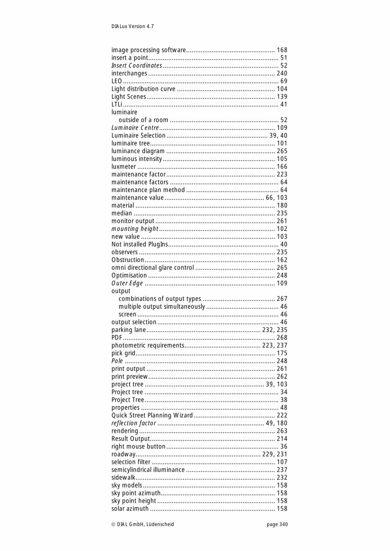
DIALux Version 4.7
DIAL GmbH, Lüdenscheid page 340
image processing software................................................. 168 insert a point........................................................................ 51 Insert Coordinates ................................................................ 52 interchanges ...................................................................... 240 LEO...................................................................................... 69 Light distribution curve ...................................................... 104 Light Scenes....................................................................... 139 LTLi ...................................................................................... 41 luminaire
outside of a room ............................................................ 52 Luminaire Centre................................................................ 109 Luminaire Selection........................................................ 39, 40 luminaire tree..................................................................... 101 luminance diagram ............................................................ 265 luminous intensity .............................................................. 105 luxmeter ............................................................................ 166 maintenance factor ............................................................ 223 maintenance factors ............................................................ 64 maintenance plan method ................................................... 64 maintenance value....................................................... 66, 103 material ............................................................................. 180 median .............................................................................. 235 monitor output .................................................................. 261 mounting height ................................................................ 102 new value .......................................................................... 103 Not installed PlugIns............................................................. 40 observers ........................................................................... 235 Obstruction........................................................................ 162 omni directional glare control ............................................ 265 Optimisation ...................................................................... 248 Outer Edge ........................................................................ 109 output
combinations of output types ........................................ 267 multiple output simultaneously ........................................ 46 screen .............................................................................. 46
output selection................................................................... 46 parking lane............................................................... 232, 235 PDF .................................................................................... 268 photometric requirements.......................................... 223, 237 pick grid............................................................................. 175 Pole ................................................................................... 248 print output ....................................................................... 261 print preview...................................................................... 262 project tree .................................................................. 39, 103 Project tree .......................................................................... 34 Project Tree.......................................................................... 38 properties ............................................................................ 48 Quick Street Planning Wizard............................................. 222 reflection factor ........................................................... 49, 180 rendering ........................................................................... 263 Result Output..................................................................... 214 right mouse button.............................................................. 36 roadway..................................................................... 229, 231 selection filter .................................................................... 107 semicylindrical illuminance ................................................. 237 sidewalk............................................................................. 232 sky models ......................................................................... 158 sky point azimuth............................................................... 158 sky point height ................................................................. 158 solar azimuth ..................................................................... 158
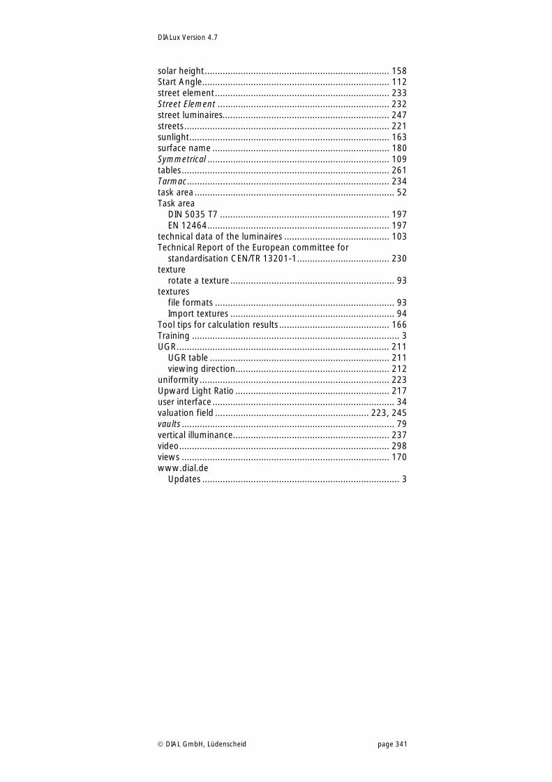
DIALux Version 4.7
DIAL GmbH, Lüdenscheid page 341
solar height........................................................................ 158 Start Angle......................................................................... 112 street element.................................................................... 233 Street Element ................................................................... 232 street luminaires................................................................. 247 streets................................................................................ 221 sunlight.............................................................................. 163 surface name ..................................................................... 180 Symmetrical ....................................................................... 109 tables................................................................................. 261 Tarmac............................................................................... 234 task area .............................................................................. 52 Task area
DIN 5035 T7 .................................................................. 197 EN 12464....................................................................... 197
technical data of the luminaires ......................................... 103 Technical Report of the European committee for
standardisation CEN/TR 13201-1.................................... 230 texture
rotate a texture ................................................................ 93 textures
file formats ...................................................................... 93 Import textures ................................................................ 94
Tool tips for calculation results ........................................... 166 Training ................................................................................. 3 UGR................................................................................... 211
UGR table ...................................................................... 211 viewing direction............................................................ 212
uniformity .......................................................................... 223 Upward Light Ratio ............................................................ 217 user interface ....................................................................... 34 valuation field ............................................................ 223, 245 vaults ................................................................................... 79 vertical illuminance............................................................. 237 video.................................................................................. 298 views ................................................................................. 170 www.dial.de
Updates ............................................................................. 3
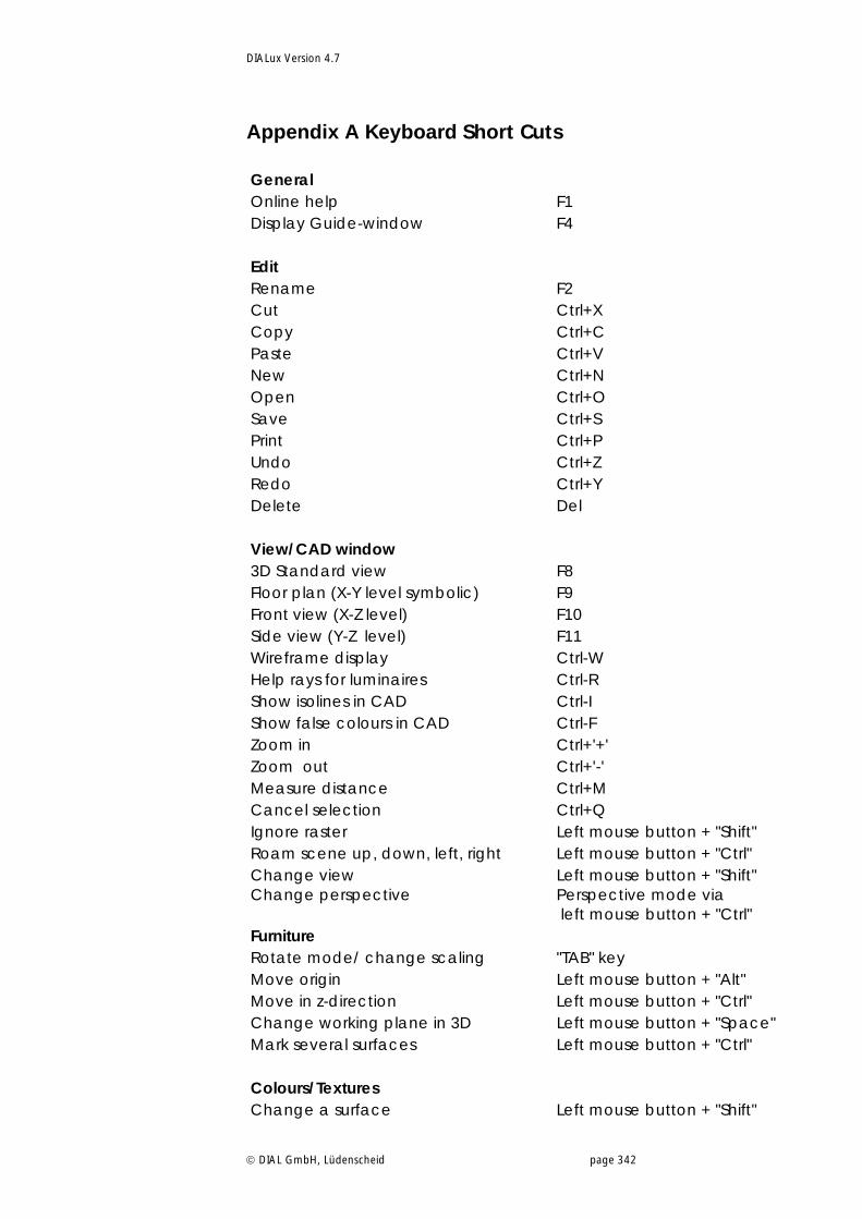
DIALux Version 4.7
DIAL GmbH, Lüdenscheid page 342
Appendix A Keyboard Short Cuts General Online help F1 Display Guide-window F4 Edit Rename F2 Cut Ctrl+X Copy Ctrl+C Paste Ctrl+V New Ctrl+N Open Ctrl+O Save Ctrl+S Print Ctrl+P Undo Ctrl+Z Redo Ctrl+Y Delete Del View/CAD window 3D Standard view F8 Floor plan (X-Y level symbolic) F9 Front view (X-Z level) F10 Side view (Y-Z level) F11 Wireframe display Ctrl-W Help rays for luminaires Ctrl-R Show isolines in CAD Ctrl-I Show false colours in CAD Ctrl-F Zoom in Ctrl+'+' Zoom out Ctrl+'-' Measure distance Ctrl+M Cancel selection Ctrl+Q Ignore raster Left mouse button + "Shift" Roam scene up, down, left, right Left mouse button + "Ctrl" Change view Left mouse button + "Shift" Change perspective Perspective mode via
left mouse button + "Ctrl" Furniture Rotate mode/ change scaling "TAB" key Move origin Left mouse button + "Alt" Move in z-direction Left mouse button + "Ctrl" Change working plane in 3D Left mouse button + "Space" Mark several surfaces Left mouse button + "Ctrl" Colours/Textures Change a surface Left mouse button + "Shift"
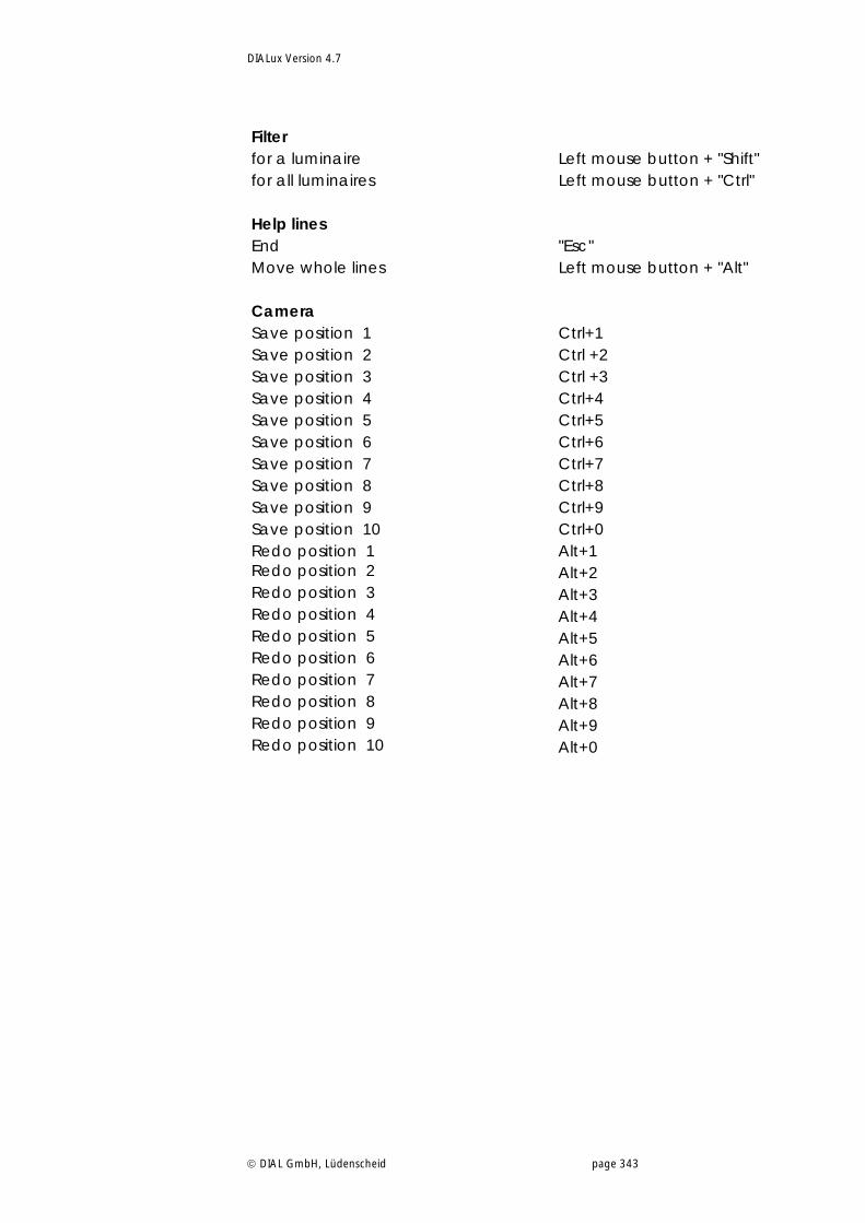
DIALux Version 4.7
DIAL GmbH, Lüdenscheid page 343
Filter for a luminaire Left mouse button + "Shift" for all luminaires Left mouse button + "Ctrl" Help lines End "Esc" Move whole lines Left mouse button + "Alt" Camera Save position 1 Ctrl+1 Save position 2 Ctrl +2 Save position 3 Ctrl +3 Save position 4 Ctrl+4 Save position 5 Ctrl+5 Save position 6 Ctrl+6 Save position 7 Ctrl+7 Save position 8 Ctrl+8 Save position 9 Ctrl+9 Save position 10 Ctrl+0 Redo position 1 Alt+1 Redo position 2 Alt+2 Redo position 3 Alt+3 Redo position 4 Alt+4 Redo position 5 Alt+5 Redo position 6 Alt+6 Redo position 7 Alt+7 Redo position 8 Alt+8 Redo position 9 Alt+9 Redo position 10 Alt+0


