Download - Installation Tips & Techniques

Installation Tips & Techniques

Installation Tips & Techniques
www.royalbuildingproducts.com
Tools • Safety glasses and power miter saw: carbide saw blade with 80
teeth or more recommended.• Miter box and hand saw: Limited angle adjustment (not
recommended for crown).• Coping saw: Only needed if you choose the coping technique to
install the moulding.• Angle gage: To create the correct miter, you must determine the
wall corner angle.• Glue: To adhere the miter joints, Royal Building Products strongly
recommends gluing all joints with PVC cement or using the OSI® TRIMTeQ™ System.
• Hammer & nails or a pneumatic nail gun.
Other tools may include a tape measure, pencil, C-clamp, putty and caulk.
CuttingUse standard woodworking equipment for cutting. If using a power miter saw, a carbide toothed blade is recommended. Use any brand of spray furniture polish on saw blade as a lubricant for easier cutting.
Wall AnglesIt will also benefit you to measure the wall angles on each corner. This will help you calculate the correct miter angle. NOTE: It is not uncommon for corner angles in most homes to be off as much as 3°. If you were installing 5” crown moulding the 3° difference would result in a 3/8” gap in the miter joint. To help you calculate the proper angle Royal has an angle calculator listed on their web site, www.royalbuildingproducts.com.
• Left and Right hand positioning: the side of the trim you are cut-ting is as important as its position on the saw table. The positions are illustrated above.
Vertical Miters Use this technique for cutting baseboard, chair rail, quarter round, and splice miters. Align trim back against fence.
Inside corners: A left hand inside corner is shown in the photo.• Step 1: Place the trim on the saw table in
the left hand vertical position and rotate the angle gage “clock wise” to 45°, or the desired angle setting, and make the cut.
• Step 2: To cut the mating piece, simply rotate the table angle gage to the opposite 45° or desired angle, and place the next piece of trim on the saw table in the right hand vertical position. Cut the trim.
Outside Corners: A right hand outside corner is shown in the photo.• Step 1: To complete this, place the trim on the saw table in the
right hand vertical position and rotate the angle gage “clock wise” to 45°, or preferred angle setting, and make the cut.
• Step 2: To cut the mating piece simply rotate the table angle gage to the opposite 45° or desired angle, and place the next piece of trim on the saw table in the left hand verti-cal position.
Horizontal Miters Use this technique for cutting window and door casings. Align trim back on saw table.
• Step 1: A left hand miter is shown in the photo to the right. To get the setup in the photo, adjust the saw table angle to the “clock wise” 45° or predetermined angle. Then lay the trim on the table in the left hand horizontal position and proceed to cut. • Step 2: To cut the mating piece simply rotate
the table angle to the opposite 45° or preferred angle, and place the next piece of trim on the saw table in the right hand horizontal position. After the cut is made the miter joints are ready for assembling.
Compound Position Miters Use this technique for cutting Crown moulding. This is the most complicated of all the mitering cuts. Note: When cutting Crown Mouldings in the compound position, remember “upside down & backwards”. This term is used because the “TOP” of the trim that is positioned against the ceiling after installation rests on the saw table during the mitering process, and the “BACK” of the trim that is placed against the wall, after instal-lation, is set against the fence dur-ing the cutting procedure.
Compound Inside Corner Miters Left hand inside corner miter shown in photo.
Step 1: Place the top of the profile against the saw table and the back of the profile against the fence in a left hand compound position. Then adjust the table angle gage “clock wise” to 45° or
calculated angle, and cut.Step 2: Place the top of the profile against the saw table and the back of the profile against the fence in a right hand com-pound position. Then move the table angle gage the opposite calculated angle, and cut.

800-368-3117
Installation Tips & Techniques
Compound Outside Corner Miters Left hand outside corner miter shown in photo.
• Step 1: The trim should lie on the saw table in a left hand compound position. The saw is to be adjusted “counter clock-wise” to the calculated angle before cutting.
• Step 2: Put the mating piece of trim on the saw in the right hand compound position. Then move the table angle gage to the opposite cal-culated angle and cut. The miter joint is ready to be put together.
Splice Miters This technique is used to join mouldings together in a linear run or when a wall is longer than the trim you are installing.
Most splice cuts are made in the ver-tical position. In the photo below of a splice miter, note the only change made in producing the joint is the right hand & left hand positions. The saw angle should remain at the same 45° setting.
Return Miters This technique is utilized when moulding ends with an exposed, unfinished end that would require finishing “paint, stain, etc.” This miter joint will create a finished edge.
• Step 1: To produce this miter, cut the trim as though you were turning an outside corner (45° saw setting).
• Step 2: Rotate the saw to the opposite 45° and cut a short piece to mate to the first cut. Glue miter joint together before attach-ing trim to wall. See photo below.
Coping Joints Coping is simply transferring the con-tour “profile” of one piece of trim to the end of another piece of trim, then cutting the profile line so that, when fin-ished, the second piece of trim will mate with the first with a nice joint.
• Step 1: Cut the first piece of trim to length and position it on the wall. Use straight cuts, no angles.
• Step 2: To create the profile line, cut the second piece of mould-ing at a 45° as though you were cutting an inside corner.
• Step 3: Following the profile line as a guide cut the trim with a coping saw.
• Step 4: The moulding should be ready for installation.
NailingInstall never rot mouldings and trim using 6d and 8d galvanized nails and/or recommended adhesives (see chart in the gluing section). Place nails 12” on center. Nails should be approxi-mately 3⁄4” from each edge. If nailing product at 40˚F or below, pre-drilling is required. Pneumatic nailing is also recommended.
Fastening Trim BoardUse fasteners designed for wood trim and wood siding (thinner shank, blunt head, full round head) with trim board. Use only fasteners intended for exterior use such as stainless steel or hot-dipped galvanized.
DO NOT USE staples, small brads and wire nails. The fasteners should be long enough to penetrate the solid wood substrate a minimum of 1-1/2”.
Use two fasteners per every framing member for trim board applications. Trim boards 12” or wider as well as sheets will require additional fasteners. Fasteners must be installed no more than 2” from the end of each board.
Trim boards should be fastened into a flat, solid substrate. Fastening trim boards into hollow or uneven areas must be avoided. Unless product is installed in lower temperatures (< 40°F) pre-drilling is typically not required. Thinner trim products (3/8” and 1/2”) are not intended to be ripped into trim pieces. They are to be glued to a substrate and mechanically fastened.
Using TRIMTeQ to Fasten Trim BoardThe OSI® TRIMTeQ™ System is specifically designed for exte-rior PVC trim installs.
It features innovative fastening and sealing products along with a comprehensive training program designed specifically for cel-lular PVC trim installation. It is formulated to maintain long last-ing durability and aesthetics that home owners expect.
PVC Trim products will expand and contract with changes in temperatures. A proper installation utilizing the TRIMTeQ™ system will minimize the movement that occurs due to changes in temperatures and help maintain a long lasting quality instal-lation.
What products are part of the OSI® TRIMTeQ™ system?• OSI® TRIMTeQ™ TeQ Mount™ – Fast Grab Polyurethane
Mounting Adhesive• OSI® TRIMTeQ™ TeQ Bond™ – Miter & Scarf Joint Adhesive• OSI® TRIMTeQ™ TeQ Fasteners™ – PVC Trim Screws & Plugs
featuring the Cortex® hidden fastener system• OSI® QUAD® Advanced Formula Sealant – Finishing Sealant• OSI® EP-1000 – Control / Expansion Joint Sealant
Next we will demonstrate how to properly install Cellular PVC trim to the exterior of a home with the OSI® TRIMTeQ™ system.
1. First mount PVC Trim to the House using OSI® TRIMTeQ™ TeQ Mount™a. OSI® TeQ Mount™ is a mounting adhesive specifically
designed to fasten cellular PVC trim board to the exte-rior of a home.
b. It features an innovative fast grab formula with durable polyurethane strength. TeQ Mounts premium formula is water and weatherproof and will last as long as the surfaces it joins together.
c. Make sure all surfaces are dry and fee of dust, dirt, oil and other foreign materials.
d. Standing surface water or ice will interfere with bond-ing.
e. Cut spout to desired bead size (1/4” recommended) and pierce inner seal.
f. Apply adhesive to the back of the PVC trim board.g. Some manufacturers require a stop, start diagonal line
pattern with a bead size of 1/4”– 3/8” diameter on to the substrate area (Figure 1).

Installation Tips & Techniques
www.royalbuildingproducts.com
h. The stop, start diagonal line pattern is designed to chan-nel water down away from the home.
i. Press the PVC trim board to the exterior of the home firmly. OSI® TeQ Mount™ will bridge 3/8” gap and helps minimize the boards thermal movement (Figure 2).
j. OSI® TeQ Mount™ meets APA AFG-01, ASTM C-557, ASTM D-3498 and conforms to HUD UM 60a.
2. Next mechanically Fasten the PVC Trim board to the housea. Use OSI® TRIMTeQ™ TeQ Fasteners™ concealed fasten-
ing system.b. TeQ Fasteners™ are specifically designed to fasten
cellular PVC trim to the home. It features the Cortex™ concealed fastening system that is virtually invisible pro-viding the professional finish that homeowners expect.
c. TeQ Screws offer the highest level of connection strength while also creating a consistently cored hole for the PVC plug connection. Each TeQ Screw is coated using a pro-prietary coating process.
d. The setting tool is engineered to ensure that the fasten-ers are set to the correct depth every time (Figure 3).
e. Each PVC plug has been engineered to ensure ultimate long term performance against outdoor elements.
f. Use a high voltage impact drill with the setting tool, drive the fastener to the preset level below the trim surface.
g. The fastener must be driven perpendicular to the surface (Figure 4).
TIP: In general, use two fasteners at every framing member at 16” on center or less. Use three fasteners if the board is wider than 8” (Figures 5 & 6).
3. Setting the TeQ PVC pluga. To ensure a strong bond, the cored hole must be free of
dirt or rain water.b. Place the plug into the hole with the trim surface side up
and gently tap until flush with the trim (Figures 7 & 8).
TIP: Be careful to ensure that the head of the hammer is flat with the trim surface to eliminate potential marring (Figs. 9 & 10).
c. Under some conditions, you may see a subtle indication that there is a doweled plug in the trim. It is recommend-ed that you test the system on a few boards to ensure you approve the final look.
TIP: To remove a fastener set below the trim surface, replace the setting tool in your impact driver with a #1 square drive bit, allow-ing full access to the seated fastener.
4. Gluing a Miter or Scarf Jointa. To achieve an optimum bond at the miter and scarf joint
apply OSI® TRIMTeQ™ TeQ Bond™ PVC Adhesive.b. TeQ Bond™ is specifically designed to adhere PVC miter
and scarf joints. Its premium formula provides a perma-nent durable bond that prevents joint separation. The innovative formula provides UV resistance and is water and weatherproof.
c. Make sure all surfaces are dry and free of dust, dirt, oil and other foreign materials. Apply a small bead to one side of the joint and apply moderate pressure (Figures 11 & 12 miter joint, Figures 13 & 14 scarf joint).
Figure 1 Figure 2
Figure 3
Figure 4
Figure 5 Figure 6
Figure 7 Figure 8
Figure 9 Figure 10

Installation Tips & Techniques
800-368-3117
d. The glue joint should be secured with a fastener and / or fastened to the home on each side of the joint to allow for proper contact of the boards being glued together and adequate bonding time (Figure 15).
e. OSI® TeQ Bond has a working time of 5 minutes and will be fully cured in 24 hours.
f. Apply OSI TeQ Mount to the back of the trim board and press firmly to the exterior of the home (follow instruc-tions from earlier).
g. Next, install the OSI TeQ Fasteners (follow instructions from earlier).
5. Finishing Sealant Instructionsa. OSI® QUAD® Advanced
Formula Sealant is recom-mended for all finishing applications.
b. OSI® QUAD® is a premium all weather sealant and pro-vides a superior long lasting durable seal.
c. It is recommended that OSI® QUAD® be applied to the void where the trim meets the siding.
d. Applying the right amount of sealant is the most impor-tant step when sealing gaps.
e. To achieve the right amount cut the tip at a 70° angle.f. With Quad’s break-away seal all you need to do is load
the gun, apply pressure to the trigger and you are ready to seal.
g. It is important that a 1/8” gap be left between the siding & trim. This allows for expansion and contraction and allows for enough room for the siding to move as the building settles.
h. It is important to caulk with a 1/4”–3/8” rounded bead.i. Use a thick rounded bead to maintain the proper amount
of sealant once it fully cures; because Quad naturally shrinks, tooling is neither needed or recommended (Figure 16).
j. Seal all end joints; end joints are where the siding meets a piece of trim around windows, doors and corners of the house.
k. The resulting seal will accommodate joint movement and provide superior UV resistance.
BEST PRACTICE TIP: Make sure to seal all gaps around exterior penetrations such as dryer vents, exterior lights, pips, electrical wires and water spigots.
GluingGluing Miter Joints Royal Building Products strongly recommends gluing all miter joints on PVC mouldings using a quality instant glue, PVC cement or OSI TeQ Bond. It may seem unconventional, but the benefits out weigh the inconvenience. When assembling splice and return miters try gluing the mouldings together before installation. This will allow you to fit the joints uninhibited, and fasten the trim to the wall as one unit. Fitting these joints on the wall can be difficult and possibly jeopardize the integrity of the miter joint.
Fastening Moulding and Trim to the Wall PVC trim can be nailed with finishing nails and/or glued. Our rec-ommendations for the nails are paneling, finishing, or pneumatic finish nails. For the glue, recommended products are PL Glues/PC —200, 300, 400/LIQUID NAILS applied according to manufac-turer’s directions. Glue alone is not advised for crown mouldings.
Adhesive Selection for Cellular PVCThe following brands have been laboratory tested and approved for use with Royal cellular PVC; however, individual conditions may vary and these adhesives may not perform under every circumstance. Other brands may also be suitable, but always test before using.
G: Good Bond F: Fair Bond P: Poor BondInt/Ext Adhesive Wood Masonry Steel OSI® TeQ Mount™ G G F Better Than Nails® G G F Liquid Nails LN-901 G G – Heavy Duty®Dow 100% Silicone® F – F Dap 230 Latex® F – P Contech PL-400® F – F
Expansion and Contraction: Royal Building Products exterior PVC products, as manufactured, may expand and contract due to temperature variations. To reduce or eliminate open joints, the preferred method is the use of PVC cement (also called pipe glue) or OSI TeQ Bond. When bonded correctly with one of these adhe-sives, the joint becomes an integral part of the system to which it is being applied.
Figure 11 Figure 12
Figure 14
Figure 13
Figure 15
Figure 16
Installation Tips & Techniques
www.royalbuildingproducts.com
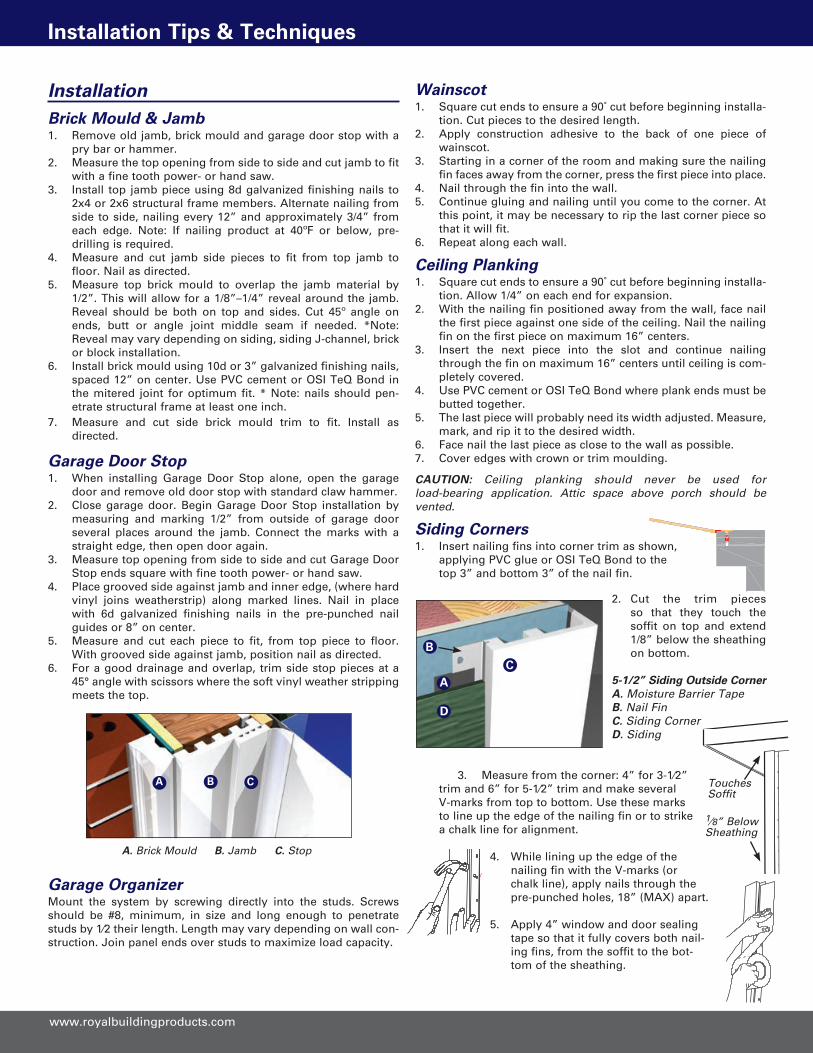
InstallationBrick Mould & Jamb1. Remove old jamb, brick mould and garage door stop with a
pry bar or hammer.2. Measure the top opening from side to side and cut jamb to fit
with a fine tooth power- or hand saw.3. Install top jamb piece using 8d galvanized finishing nails to
2x4 or 2x6 structural frame members. Alternate nailing from side to side, nailing every 12” and approximately 3/4” from each edge. Note: If nailing product at 40ºF or below, pre-drilling is required.
4. Measure and cut jamb side pieces to fit from top jamb to floor. Nail as directed.
5. Measure top brick mould to overlap the jamb material by 1/2”. This will allow for a 1/8”–1/4” reveal around the jamb. Reveal should be both on top and sides. Cut 45º angle on ends, butt or angle joint middle seam if needed. *Note: Reveal may vary depending on siding, siding J-channel, brick or block installation.
6. Install brick mould using 10d or 3” galvanized finishing nails, spaced 12” on center. Use PVC cement or OSI TeQ Bond in the mitered joint for optimum fit. * Note: nails should pen-etrate structural frame at least one inch.
7. Measure and cut side brick mould trim to fit. Install as directed.
Garage Door Stop1. When installing Garage Door Stop alone, open the garage
door and remove old door stop with standard claw hammer.2. Close garage door. Begin Garage Door Stop installation by
measuring and marking 1/2” from outside of garage door several places around the jamb. Connect the marks with a straight edge, then open door again.
3. Measure top opening from side to side and cut Garage Door Stop ends square with fine tooth power- or hand saw.
4. Place grooved side against jamb and inner edge, (where hard vinyl joins weatherstrip) along marked lines. Nail in place with 6d galvanized finishing nails in the pre-punched nail guides or 8” on center.
5. Measure and cut each piece to fit, from top piece to floor. With grooved side against jamb, position nail as directed.
6. For a good drainage and overlap, trim side stop pieces at a 45° angle with scissors where the soft vinyl weather stripping meets the top.
Garage OrganizerMount the system by screwing directly into the studs. Screws should be #8, minimum, in size and long enough to penetrate studs by 1⁄2 their length. Length may vary depending on wall con-struction. Join panel ends over studs to maximize load capacity.
Wainscot1. Square cut ends to ensure a 90˚ cut before beginning installa-
tion. Cut pieces to the desired length.2. Apply construction adhesive to the back of one piece of
wainscot.3. Starting in a corner of the room and making sure the nailing
fin faces away from the corner, press the first piece into place.4. Nail through the fin into the wall.5. Continue gluing and nailing until you come to the corner. At
this point, it may be necessary to rip the last corner piece so that it will fit.
6. Repeat along each wall.
Ceiling Planking1. Square cut ends to ensure a 90˚ cut before beginning installa-
tion. Allow 1/4” on each end for expansion.2. With the nailing fin positioned away from the wall, face nail
the first piece against one side of the ceiling. Nail the nailing fin on the first piece on maximum 16” centers.
3. Insert the next piece into the slot and continue nailing through the fin on maximum 16” centers until ceiling is com-pletely covered.
4. Use PVC cement or OSI TeQ Bond where plank ends must be butted together.
5. The last piece will probably need its width adjusted. Measure, mark, and rip it to the desired width.
6. Face nail the last piece as close to the wall as possible.7. Cover edges with crown or trim moulding.
CAUTION: Ceiling planking should never be used for load-bearing application. Attic space above porch should be vented.
Siding Corners1. Insert nailing fins into corner trim as shown,
applying PVC glue or OSI TeQ Bond to the top 3” and bottom 3” of the nail fin.
2. Cut the trim pieces so that they touch the soffit on top and extend 1/8” below the sheathing on bottom.
5-1/2” Siding Outside CornerA. Moisture Barrier TapeB. Nail Fin C. Siding Corner D. Siding
3. Measure from the corner: 4” for 3-1⁄2” trim and 6” for 5-1⁄2” trim and make several V-marks from top to bottom. Use these marks to line up the edge of the nailing fin or to strike a chalk line for alignment.
4. While lining up the edge of the nailing fin with the V-marks (or chalk line), apply nails through the pre-punched holes, 18” (MAX) apart.
5. Apply 4” window and door sealing tape so that it fully covers both nail-ing fins, from the soffit to the bot-tom of the sheathing.
A. Brick Mould B. Jamb C. Stop
A B C Touches Soffit
1⁄8” Below Sheathing
A
B
D
C

800-368-3117
Installation Tips & Techniques
PaintingPainting Cellular PVCRoyal’s factory applied finish requires no painting for protection. Desired custom finishes can be achieved using acrylic latex paints. To main-tain warranty for custom colors in darker shades, use of paints with VinylSafe™ Technology from Sherwin Williams is recommended. (Dark colors are considered any color that falls within the lightness (L) value of 56 to 0 noting that 100 is white and 0 is black.)
Trim board requires no painting for protection but can be painted with 100% acrylic latex paint to achieve custom colors. Scuff sanding will optimize paint adhesion but is not required. Apply a second coat (if required to achieve desired color).
Touch-Up for Exterior Mouldings• Dap® “All Purpose” Painter’s Putty® • Minwax High Performance Wood Filler® • Elmer’s Fill-N-Finish Light Wood Filler® • Sherwin Williams Shrink Free Spackling® After installation is complete, caulk and/or putty all gaps and nail holes.
StainingInstructions are intended to give general overview of various methods & techniques for stainable products. Work with sample profile to test stain and develop proper color before starting project. Tools for staining: • Stain or Glaze – Heavy body or high pigment EXTERIOR gel stains perform best. • Top Coat –Select topcoat that corresponds with application as well as stain type (oil, water base, etc.) • Foam Brush – to apply initial coat of stain or glaze • Soft Badger Hair Brush – used to blend or soften a finish. • Rags – Soft cotton is recommended • Safety products – safety glasses, gloves, and garment protection. Step 1: Follow manufacturer’s recommendations for Stain or glaze. Using foam brush, saturate product surface with stain or glaze and allow coating to “rest or soak” for five minutes.
Step 2: Start wiping stain or glaze with cloth. The amount wiped will determine end color. Start with light touch in one direc-tion only. Vary amount wiped to create natural color vari-ation found in real wood. Allow some coating to remain in embossed areas to achieve graining effect.
Step 3: Use Soft Badger Hair brush to blend and soften the coating. Additional coats may be added to darken an area, but use small amounts and dry brush periodically. A few points to remember: • Use soft brush and long strokes. Soft badger bristles and light pressure will achieve the desired coating. • A cross-hatching motion will blend color and soften appearance. • Stippling “Pouncing action” will add color back to the product. • Intentionally leave dark and light areas to achieve more natural wood effect. Step 4: Always apply topcoat for protection. Type of topcoat must be compatible with exterior gel stain used.
Finishing clearwood profilesPrepare1. DO NOT SAND.2. If cleaning is necessary, wipe with mineral spirits, naphtha or
ammonia.3. For best results use a water based putty or filler after staining to
fill nail holes, seams and miters. 4. For best results, test your stain before starting your project.
Always use new or reasonably new finishing materials that have not been stored outside in extreme cold or heat. Follow instruc-tions on can.
PaintClearwood profiles are easily painted, usually with one coat. Apply any oil or latex paint with a brush, roller or sprayer.
Stain1. Use a penetrating oil base stain. Shake well. Stir often. 2. Apply stain with lint-free cloth or brush. When using a brush,
remove the excess liquid from the bristles before applying stain.3. Allow stain to dry, usually 5-15 minutes. (Follow stain can instruc-
tions.)4. Buff w/ lint-free rag to bring out the grain.5. If darker color is desired, apply a second coat after 4-6 hours. The
stain will continue to be absorbed after Clearwood PS appears to be dry.
6. When the second coat looks dry, buff to bring out the grain.
TopcoatAfter stain has dried thoroughly, apply a clear polyurethane topcoat with a brush or spray. Lacquers & acrylics must be sprayed, not brushed.
CleaningExterior Mouldings and TrimCleaning Royal Building Products is easy and fast with most major household cleaners. There are many cleaners on the market and the glass cleaners seem to be the best candidate for keeping the finish intact. The cleaning solution should be applied and immediately wiped dry. With any cleaning material, the cleaning solution should not be left to stand on the components for an extended period of time. Royal Building Products recommends the following cleaners:
Windex® 409 Glass and Surface Cleaner® Spic & Span Cinch® Fantastik All-Purpose® Fantastik Orange Action® Regency® (Glass and Surface) Clorox Clean-Up® Glass Plus® Fantastik Oxy Power Multi-Purpose Cleaner®
What to AvoidHarsh cleaners with glycol ethers or ethanol type solvents and/or isopropyl alcohol soften the coating if left on for several minutes and are not recommended. Examples of these harmful cleaners are Goof Off®, Wal-Mart “Great Value All Purpose Cleaner®” (glycol ether), 409 General Purpose® (2-Butoxyethanol) and Greased Lightning® (glycol ether), citrus cleaners, abrasive cleaners, and solvents such as acetone, paint remover and lacquer.
Cleaning Interior MouldingsTo clean finished clearwood mouldings gently wipe with damp rag.
Storage & HandlingRoyal trim materials should be stored on a flat and level surface on a full shipping pallet. Handle materials to prevent damage to product edges and corners. Store trim under protective covering to prevent jobsite dirt and residue from collecting on trim.

800-368-3117 RBP111811
Installatio
n T
ips &
Tech
niq
ues
800.368.3117 ww
w.ro
yalbu
ildin
gp
rod
ucts.co
m
Toll Free Ordering & Information ...... 800-368-3117Local & International ......................... (276) 783-8161
Fax....................................................... (276) 782-3292
Website ............... www.royalbuildingproducts.com
Hours ...................................................8am-5pm EST
Royal Building Products135 Bear Creek Rd • P.O. Box 610
Marion VA 24354
Distributed by:


