PAS 1192-2:2013Incorporating Corrigendum No. 1
Specifi cation for information management for the capital/delivery phase of construction projects using building information modelling
Publishing and copyright informationThe BSI copyright notice displayed in this document indicates when the document was last issued.
© The British Standards Institution 2013. Published by BSI Standards Limited 2013.
ISBN 978 0 580 82666 5
ICS 91.010.01
No copying without BSI permission except as permitted by copyright law.
Publication history
First published February 2013
Amendments issued since publication
Date Text affected
28 March 2013 Corrigendum No. 1 to correct Figures 2, 7, 14, 20 and 21
i
PAS 1192-2:2013
© The British Standards Institution 2013
Contents
Foreword .................................................................................................... iii
Introduction ................................................................................................ v
1 Scope ........................................................................................................ 1
2 Normative references ............................................................................. 2
3 Terms and defi nitions ............................................................................. 3
4 Overview of documents referenced from this specifi cation ............... 7
5 Information delivery – Assessment and need ...................................... 95.1 General ................................................................................................. 95.2 Origin of the employer’s information requirements (EIR) ................. 105.3 Contents of the employer’s information requirements (EIR) ............ 10
6 Information delivery – Procurement ..................................................... 126.1 General ................................................................................................. 126.2 Production of the pre-contract BIM execution plan (BEP) ................ 146.3 Project implementation plan (PIP) ...................................................... 146.4 Supplier BIM assessment form ........................................................... 146.5 Supplier information technology (IT) assessment form .................... 156.6 Supplier resource assessment form .................................................... 156.7 Supply chain capability summary form ............................................... 15
7 Information delivery – Post contract-award ......................................... 167.1 General ................................................................................................ 167.2 Production of the post contract-award BIM execution plan (BEP) .. 167.3 Production of the master information delivery plan (MIDP) ........... 177.4 Task information delivery plan (TIDP) ................................................ 177.5 Project delivery team roles, responsibilities and authority .............. 177.6 Volumes ............................................................................................... 20
8 Information delivery – Mobilization ...................................................... 23
9 Information delivery – Production ......................................................... 249.1 General ................................................................................................. 249.2 Common data environment (CDE) ...................................................... 259.3 File and layer naming conventions ..................................................... 299.4 Spatial co-ordination ........................................................................... 299.5 Publication of information .................................................................. 329.6 Design for bespoke manufacture ........................................................ 329.7 Using assemblies and library information ......................................... 329.8 Levels of model defi nition ................................................................... 339.9 Levels of model detail and model information .................................. 339.10 Classifi cation ....................................................................................... 41
ii
PAS 1192-2:2013
© The British Standards Institution 2013
10 Information delivery – Asset information model (AIM) maintenance .... 4210.1 General – information delivery – Asset information model (AIM) maintenance ............................................................................................... 4210.2 Handover process between CAPEX and OPEX ................................. 43
AnnexesAnnex A (informative) Terms, defi nitions and abbreviations for BIM documentation ........................................................................................... 44
Bibliography ............................................................................................... 53
List of fi guresFigure 1 – BIM maturity levels ................................................................... viiFigure 2 – The information delivery cycle ................................................. viiiFigure 3 – The relationships between the contract and the associated documents .................................................................................................. 7Figure 4 – Relationship between documents used for information management .............................................................................................. 8Figure 5 – Information delivery – Assessment and need ......................... 9Figure 6 – Information delivery – Procurement ....................................... 12Figure 7 – The whole supply chain contributes information to answer the Plain Language questions ................................................................... 13Figure 8 – Relationship between documents used for information management .............................................................................................. 14Figure 9 – Information delivery – Post contract-award ........................... 16Figure 10 – Roles, responsibilities and authority ...................................... 18Figure 11 – Volumes within a tunnel design for spatial co-ordination .. 21Figure 12 – Volumes within a building for spatial co-ordination ........... 22Figure 13 – Information delivery – Mobilization ...................................... 23Figure 14 – Information delivery – Production ......................................... 24Figure 15 – Extending the common data environment (CDE) ................. 26Figure 16 – Architect’s issue to SHARED ................................................... 31Figure 17 – Structural engineer’s issue to SHARED .................................. 31Figure 18 – MEP engineer’s issue to SHARED ........................................... 31Figure 19 – Design review of models in SHARED ..................................... 32Figure 20 – Levels of model defi nition for building and infrastructure projects ....................................................................................................... 35Figure 21 – Information delivery – AIM maintenance ............................. 42
List of tablesTable 1 – Information modelling maturity Level 2 ................................... xTable 2 – Information exchange activities ................................................ 19Table 3 – Status codes in the CDE .............................................................. 28Table 4 – Application of different classifi cation systems ......................... 41
iii
PAS 1192-2:2013
© The British Standards Institution 2013
Foreword
This PAS was sponsored by the Construction Industry Council (CIC). Its development was facilitated by BSI Standards Limited and published under licence from The British Standards Institution. It came into effect on 28 February 2013.
Acknowledgement is given to the following organizations that were involved in the development of this specifi cation as members of the Steering Group:
• AEC3
• Atkins Limited
• Autodesk
• Bentley
• BIM4IUK
• Building SMART
• Cabinet Offi ce
• Construction Project Information Committee
• Construction Industry Council (CIC)
• Department of Business, Innovation and Skills (BIS)
• EC Strategies
• Evolve
• Hitherwood Consulting
• HM Treasury
• Kier
• Ministry of Justice
• MR1 Consulting Ltd
• OakleyCAD
• Operam Ltd
• Parsons Brinckerhoff
• Skanska
• TfL
• URS Scott Wilson
• West One Management Consulting
The British Standards Institution retains ownership and copyright of this PAS. BSI Standards Limited as the publisher of the PAS reserves the right to withdraw or amend this PAS on receipt of authoritative advice that it is appropriate to do so. This PAS will be reviewed at intervals not exceeding two years, and any amendments arising from the review will be published as an amended PAS and publicized in Update Standards.
This PAS is not to be regarded as a British Standard. It will be withdrawn upon publication of its content in, or as, a British Standard.
The PAS process enables a specifi cation to be rapidly developed in order to fulfi l an immediate need in industry. A PAS may be considered for further development as a British Standard, or constitute part of the UK input into the development of a European or International Standard.
Relationship with other publicationsThis PAS builds on the existing code of practice for the collaborative production of architectural, engineering and construction information, defi ned within BS 1192:2007.
A forthcoming document, PAS 1192-3, will offer guidance on the use and maintenance of the asset information model (AIM) to support the planned preventative maintenance programme and the portfolio management activity for the life of the asset.
Information about this documentThe start and fi nish of text introduced by Corrigendum No. 1 is indicated in the text by tags and.
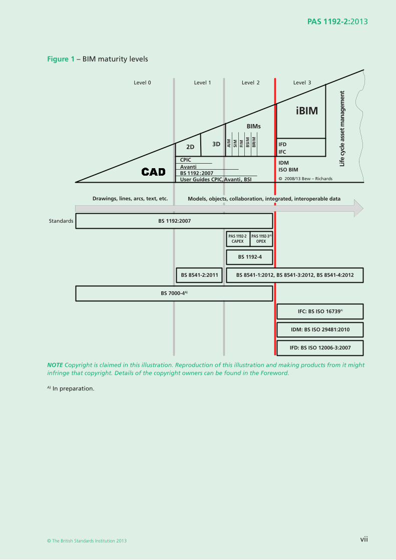
Copyright is claimed on Figure 1. Copyright holders are Mark Bew and Mervyn Richards.
Copyright is claimed on Figures 2, 3, 4, 5, 6, 7, 8, 9, 10, 11, 12, 13, 14, 15, 16, 17, 18, 19, 20. Copyright holder is Mervyn Richards.
Use of this documentIt has been assumed in the preparation of this PAS that the execution of its provisions will be entrusted to appropriately qualifi ed and experienced people, for whose use it has been produced.
iv
PAS 1192-2:2013
© The British Standards Institution 2013
Presentational conventionsThe provisions of this PAS are presented in roman (i.e. upright) type. Its requirements are expressed in sentences in which the principal auxiliary verb is “shall”. Its recommendations are expressed in sentences in which the principal auxiliary verb is “should”. The use of the auxiliary verb “can” indicates that something is technically possible and the auxiliary verb “may” indicates permission.
Commentary, explanation and general informative material is presented in smaller italic type, and does not constitute a normative element.
Spelling conforms to The Shorter Oxford English Dictionary. If a word has more than one spelling, the fi rst spelling is used.
Contractual and legal considerationsThis publication does not purport to include all the necessary provisions of a contract. Users are responsible for its correct application.
Compliance with a PAS cannot confer immunity from legal obligations.
v
PAS 1192-2:2013
© The British Standards Institution 2013
Introduction
General informationThe production of co-ordinated design and construction information is a task- and time-based process, independent of which procurement route or form of contract is used. Each task needs to be carried out in a particular order for the mutual benefi t of all those involved, otherwise known as ”collaborative working”. In a collaborative working environment, teams are asked to produce information using standardized processes and agreed standards and methods, to ensure the same form and quality, enabling information to be used and reused without change or interpretation. If an individual, offi ce or team changes the process without agreement, it will hinder collaboration – a participant insisting on “my standard” is not acceptable in a collaborative working environment.
This approach does not require more work, as this information has always been required to be produced. However, true collaborative working requires mutual understanding and trust within the team and a deeper level of standardized process than has previously been experienced, if the information is to be produced and delivered in a consistent timely manner. The benefi ts of working in this way can include fewer delays and disputes within the team, better management of project risk and better understanding of where costs are being incurred.
Wherever possible, the principles of lean should also be applied to reduce the expenditure of resources for any goal other than the creation of value for the employer. For example, BS 1192:2007 promotes the avoidance of wasteful activities such as:
• waiting and searching for information;
• over-production of information with no defi ned use;
• over-processing information, simply because the technology can; and
• defects, caused by poor co-ordination across the graphical and non-graphical data set which require rework.
However, for the production of information to be truly lean, it is critical to understand its future use. This is achieved by “beginning with the end in mind” and identifying the downstream uses of information, to ensure information can be used and re-used throughout the project and life of the asset. It is to this end that PAS 1192-2 has been produced.
It is anticipated that this document is of equal value to small practices as well as large multi-nationals. The impact of poor information management and waste is potentially equal on all projects. Where appropriate we have offered some advice as to how the process and methods described here can be implemented in a scalable fashion to suit all organizations.
Background and context of PAS 1192-2In May 2011, the UK Government published the Construction Strategy aimed at reducing the cost of public sector assets by up to 20% by 2016. The strategy calls “for a profound change in the relationship between public authorities and the construction industry to ensure the Government consistently gets a good deal and the country gets the social and economic infrastructure it needs for the long-term”.
Basic problems exist with procuring public assets, which have been known for over 100 years, but little as yet has been achieved in resolving them. The Construction Strategy defi nes a number of strategic objectives, which collectively will overcome these problems. In particular, a strategic objective has been set to achieve maturity Level 2 building information modelling (BIM) on all public sector asset procurement, with equal applicability to private sector building, infrastructure, refurbishment and new-build projects. This will address the problem of information that is inaccurate, incomplete and ambiguous and results in unnecessary additional capital delivery costs amounting to 20-25% – see Avanti case studies at http://www.cpic.org.uk/en/publications/avanti.
It was envisaged that the advent of Computer Aided Design solutions had the potential to improve the consistency of information, but at best it has only served to perpetuate the problem.
vi
PAS 1192-2:2013
© The British Standards Institution 2013
This additional 20-25% is considered waste and can be reduced if the standards, processes and procedures outlined in BS 1192:2007 and this document are implemented.
This PAS is one of a number of documents published on the BIM Task Group website (http://www.bimtaskgroup.org) in support of these strategic objectives. These are as follows:
• CIC Scope of Services, First Edition, 2007;
• Outline Scope of Services for the Role of Information Management, First Edition, 2013;
• COBie-UK-2012, the fi rst edition of the UK edition of the schema for Construction Operations Building Information Exchange;
• CIC BIM Protocol, First Edition, 2013;
• Employer’s Information Requirements.
Additional information can also be found on the BIM Task Group website http://www.bimtaskgroup.org.
The BIM maturity model setting out the progression from CAD ultimately to Level 3 BIM is shown in Figure 1. More detail regarding Level 2 is given under the heading “Fundamental principles for Level 2 information modelling”, below.
The process of BIM generates information models and their associated information that are used throughout the lifecycle of building/infrastructure facilities or assets. The information delivery and project management cycle in Figure 2 shows in BLUE the generic process of identifying a project need (which may be for design services, for construction or for supply of goods), procuring and awarding a contract, mobilizing a supplier and generating production information and asset information relevant to the need. This cycle is followed for every aspect of a project, including the refi nement of design information through the seven project stages shown in GREEN.
The GREEN elements of the diagrams represent the information delivery process known as the common data environment (CDE).
A forthcoming document, PAS 1192-3, to be developed, will offer guidance on the use and maintenance of the asset information model (AIM) to support the planned preventative maintenance programme and the portfolio management activity for the life of the asset.
This document provides a framework, from which a number of supplementary documents will provide detailed guidance. Collectively, these documents will be developed further, from the learning taken from the Government’s ”early adopter” projects, and may be considered for further development as a British Standard.
PAS 1192-2 provides specifi c guidance for the information management requirements associated with projects delivered using BIM. Not all information on a project will be originated, exchanged or managed in a BIM format. This information will also need to be managed in a consistent and structured way to enable effi cient and accurate information exchange. BS 1192:2007 provides details of the standards and processes that should be adopted to deliver these outcomes. Only information exchanges specifi c to BIM are described in this PAS. It is assumed for the purposes of this standard that non-BIM information exchanges between a principal supplier and employer and within the supply chain will be managed using equivalent information management standards. Furthermore, and for the avoidance of doubt, all project information, whether in BIM environments or in conventional data formats should be shared using a single collaborative data environment (CDE).
vii
PAS 1192-2:2013
© The British Standards Institution 2013
Figure 1 – BIM maturity levels
2D 3D
BIMs
iBIM
AIM
BSI
MFI
MSI
M
BRI
M
CPICAvantiBS 1192:2007
ISO BIMIDM
Drawings, lines, arcs, text, etc.
IFCIFD
Life
cyc
le a
sset
man
agem
ent
© 2008/13 Bew – Richards
Level 0 Level 1 Level 2 Level 3
User Guides CPIC, Avanti, BSI
Models, objects, collaboration, integrated, interoperable data
BS 1192:2007Standards
PAS 1192-2CAPEX
PAS 1192-3A)
OPEX
BS 1192-4
BS 8541-2:2011
BS 7000-4A)
IFC: BS ISO 16739A)
IDM: BS ISO 29481:2010
IFD: BS ISO 12006-3:2007
BS 8541-1:2012, BS 8541-3:2012, BS 8541-4:2012
NOTE Copyright is claimed in this illustration. Reproduction of this illustration and making products from it might infringe that copyright. Details of the copyright owners can be found in the Foreword.
A) In preparation.
��
��
viii
PAS 1192-2:2013
© The British Standards Institution 2013
Figure 2 – The information delivery cycle
NEED
Employer’s InformationRequirements
(EIR)
1
2 3 4 5 6 71
2 3 6 7
1 2 3 4 5 6 7 n
DELIVERY
CONTRACT AWARD
Legend
PROCUREMENT
ASS
ESSM
ENT
MO
BIL
IZA
TIO
N
Mai
nta
in, R
efu
rbis
h, E
nd
of
Life
or
Bu
ild
MAINTENANCE and USE (PAS 1192-3)
STRATEGY
Opexstart
Capexstart
Master InformationDelivery Plan
(MIDP)
SUPPLIER’SINFORMATION
EXCHANGE
EMPLOYER’SDECISION POINT
Green Blue
EXECUTION
BIM Execution Plan(BEP)
For details on supplier’sinformation exchangesand employer’s decision
points seeCIC Scope of Services
Informationprocess
Managementprocess
Project Information Model (PIM)
HANDOVER &CLOSEOUT
BUILD &COMMISSION
OPERATION
COMMON DATA ENVIRONMENT (CDE)
IN USEDESIGNBRIEF CONCEPT DEFINITION
Asset Information Model (AIM)
Non-Graphical Data
Documentation
Info
rmat
ion
Mo
del
HA
ND
OV
ER
Graphical Model
NOTE 1 The information delivery cycle as shown in Figure 2 has two distinct points of entry. For stand-alone new-build projects, start at the top right box “Need”, but for projects that are part of a larger portfolio or estate, or for projects working on existing buildings and structures, then start at the right-hand arrow “Assessment” which draws on the information in the existing AIM. These points of entry are also referenced in the CDE – see 8.2. It is assumed that use will be made at both start points of portfolio information to inform decisions.
NOTE 2 The information delivery cycle shows in BLUE the generic process of identifying a project need (which may be for design services, for construction or for supply of goods), procuring and awarding a contract, mobilizing a supplier and generating production information and asset information relevant to the need. This cycle is followed for every aspect of a project, including the refi nement of design information through the seven project stages shown in GREEN.
NOTE 3 The GREEN numbered ovals and annotated lozenges refer to the CIC Scope of Services stages. The GREEN image represents the CDE that will collect, manage, disseminate, exchange and retrieve information through the lifecycle.
NOTE 4 Information exchanges between project team members are indicated by small GREEN balloons.
NOTE 5 Information exchanges between the project team and the employer are indicated by larger red balloons to answer the Plain Language questions posed by the employer defi ned in the employer’s information requirements (EIR) and referred to in Figure 7 (see 4.1.5).
NOTE 6 Copyright is claimed in this illustration. Reproduction of this illustration and making products from it might infringe that copyright. Details of the copyright owners can be found in the Foreword.
ix
PAS 1192-2:2013
© The British Standards Institution 2013
Fundamental principles for Level 2 information modellingThe fundamental principles of Level 2 information modelling are:
a) originators produce defi nition information in models which they control, sourcing information from other models where required by way of reference, federation or direct information exchange;
b) provision of a clear defi nition of the employer’s information requirements (EIR) and key decision points (to form part of the contract possibly through adoption of the CIC BIM Protocol) – see Clause 5;
c) evaluation of the proposed approach, capability and capacity of each supplier, and their supply chain, to deliver the required information, prior to contract award – see Clause 6;
d) a BIM execution plan (BEP) shall be developed by the supplier containing:
1) assigned roles, responsibilities and authorities;
2) standards, methods and procedures; and
3) a resourced master information delivery index, aligned with the project programme;
– see Clauses 6, 7 and 8;
e) provision of a single environment to store shared asset data and information, accessible to all individuals who are required to produce, use and maintain it – see Clause 9;
NOTE The single environment can look very different on small and large projects, which can use free web-based fi le sharing applications or sophisticated enterprise bridge software.
f) application of the processes and procedures outlined in the documents and standards indicated in Table 1; and
g) information models to be developed using one of the following combinations of enabling tools:
1) discipline-based software, with individual proprietary databases, that have limited interoperability between them or with associated design analysis software;
2) discipline-based software, with individual proprietary databases, that are fully interoperable, but with limited interoperability with associated design analysis software;
3) discipline-based software, with individual proprietary databases, and associated design analysis software that are fully interoperable; or
4) single source platform software, with a single external relational database, and associated design analysis software that are fully interoperable.
This list of combinations of enabling tools is not exhaustive.
NOTE 1 The above principles involve the delivery of a co-ordinated project information model to the employer containing graphical and non-graphical information through a single point of responsibility, likely to be the lead designer or the contractor.
NOTE 2 One of the key Level 2 requirements is the exchange standard of COBie and PDF, as well as copies of the native fi les.
NOTE 3 The defi nition of BIM maturity Level 2 was originally developed as part of the UK Government BIM strategy in 2011. The terminology has been adopted widely. Level 2 is defi ned in this PAS with reference to best practice and the adoption of tools and standards. Given the early stage of adoption of managed methods of working in BIM at the time when this PAS was drafted, it can be expected that Level 2 practice will continue to evolve and that the scope of information sharing and exchange will vary from project to project. For this reason, it can be anticipated that the defi nition of Level 2 BIM will continue to evolve around the core principle of the shared use of individually authored models in a common data environment.
x
PAS 1192-2:2013
© The British Standards Institution 2013
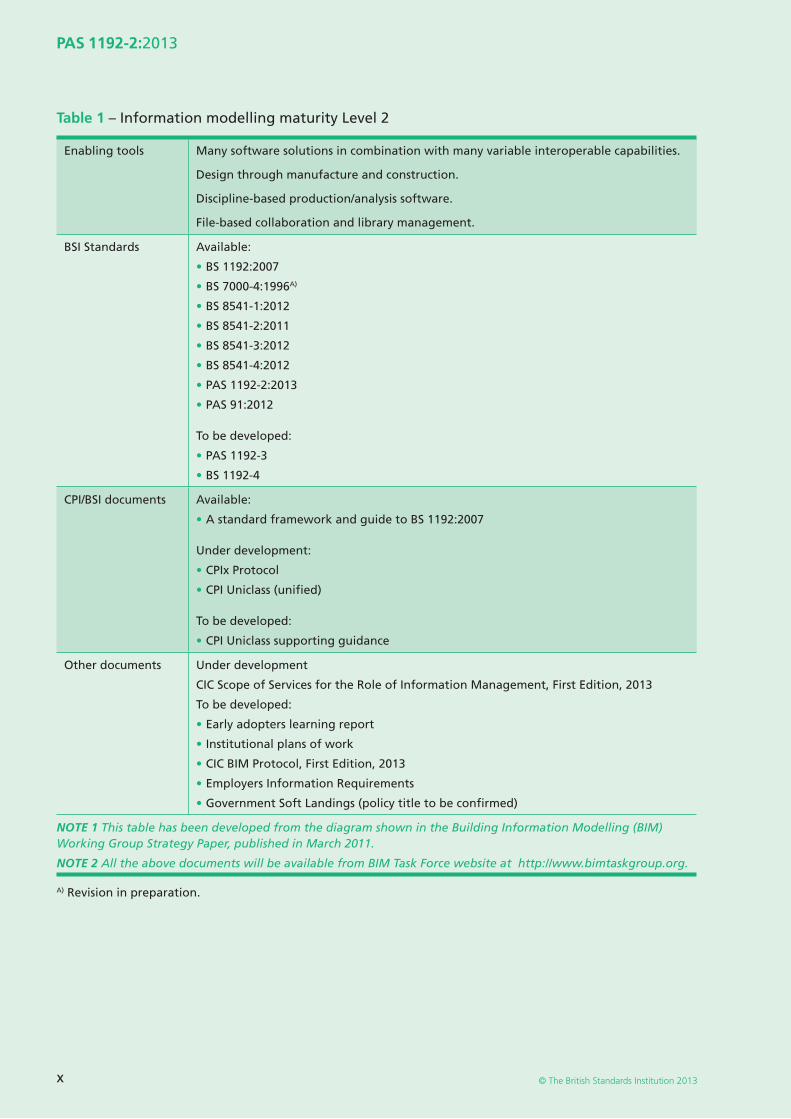
Table 1 – Information modelling maturity Level 2
Enabling tools Many software solutions in combination with many variable interoperable capabilities.
Design through manufacture and construction.
Discipline-based production/analysis software.
File-based collaboration and library management.
BSI Standards Available:
• BS 1192:2007
• BS 7000-4:1996A)
• BS 8541-1:2012
• BS 8541-2:2011
• BS 8541-3:2012
• BS 8541-4:2012
• PAS 1192-2:2013
• PAS 91:2012
To be developed:
• PAS 1192-3
• BS 1192-4
CPI/BSI documents Available:
• A standard framework and guide to BS 1192:2007
Under development:
• CPIx Protocol
• CPI Uniclass (unifi ed)
To be developed:
• CPI Uniclass supporting guidance
Other documents Under development
CIC Scope of Services for the Role of Information Management, First Edition, 2013
To be developed:
• Early adopters learning report
• Institutional plans of work
• CIC BIM Protocol, First Edition, 2013
• Employers Information Requirements
• Government Soft Landings (policy title to be confi rmed)
NOTE 1 This table has been developed from the diagram shown in the Building Information Modelling (BIM) Working Group Strategy Paper, published in March 2011.
NOTE 2 All the above documents will be available from BIM Task Force website at http://www.bimtaskgroup.org.
A) Revision in preparation.
1
PAS 1192-2:2013
© The British Standards Institution 2013
1 Scope
This Publically Available Specifi cation (PAS) specifi es requirements for achieving building information modelling (BIM) Level 2 – see Figure 1 and Table 1. The requirements within this PAS build on the existing code of practice for the collaborative production of architectural, engineering and construction information, defi ned within BS 1192:2007. PAS 1192-2 focuses specifi cally on project delivery, where the majority of graphical data, non-graphical data and documents, known collectively as the project information model (PIM), are accumulated from design and construction activities.
The intended audience for this PAS includes organizations and individuals responsible for the procurement, design, construction, delivery, operation and maintenance of buildings and infrastructure assets. Where possible, generic language has been used, but where necessary, specifi c defi nitions are in Clause 3.
Commencing at the point of assessment (for existing assets) or statement of need (for new assets) and progressively working through the various stages of the information delivery cycle, the requirements within this PAS culminate with the delivery of the as-constructed asset information model (AIM). This is handed over to the employer by the supplier once the PIM has been verifi ed against what has been constructed.
2
PAS 1192-2:2013
© The British Standards Institution 2013
2 Normative references
The following referenced documents are indispensable for the application of this document. For dated references, only the edition cited applies. For undated references, the latest edition of the referenced document (including any amendments) applies.
BS 1192:2007, Collaborative production of architectural, engineering and construction information – Code of practice
CIC BIM Protocol, First Edition, 2013 http://www.bimtaskgroup.org
RICHARDS, M. Building Information Management – A Standard Framework and Guide to BS 1192. London, UK: BSI, 2010
Uniclass documents, http://www.bimtaskgroup.org
3
PAS 1192-2:2013
© The British Standards Institution 2013
3 Terms and defi nitions
For the purposes of this PAS the following terms and defi nitions apply.
3.1 archivecomponent of the common data environment (CDE)
NOTE The archive section of the CDE is for inactive or superseded information. Such information will provide a history of the project information transfers, sharing, change orders and knowledge retention, and can be used for other contractual purposes or “discovery’”.
3.2 as-built
as-constructed
component of the common data environment (CDE)
3.3 asset information model (AIM)maintained information model used to manage, maintain and operate the asset
3.4 attributepiece of data forming a partial description of an object or entity
3.5 authororiginator of model fi l es, drawings or documents
3.6 building information modelling execution plan (BEP)plan prepared by the suppliers to explain how the information modelling aspects of a project will be carried out
3.7 building information modelling (BIM)process of designing, constructing or operating a building or infrastructure asset using electronic object-oriented information
3.8 CIC Scope of Servicesmulti-disciplinary scope of services published by the Construction Industry Council (CIC) for use by members of the project team on major projects
3.9 clash renditionrendition of the native format model fi le to be used specifi cally for spatial coordination processes
NOTE Used to achieve clash avoidance or to be used for clash detection.
3.10 classifi cationsystematic arrangement of headings and sub-headings for aspects of construction work including the nature of assets, construction elements, systems and products
3.11 clientindividual or organization commissioning a built asset
NOTE The client may be different from the employer.
3.12 COBie (Construction Operation Building information exchange)structured facility information for the commissioning, operation and maintenance of a project often in a neutral spreadsheet format that will be used to supply data to the employer or operator to populate decision-making tools, facilities management and asset management systems
NOTE Templates for the preparation of COBie-UK-2012 information exchange fi les (the schema developed for UK projects) can be downloaded from the website: http://www.bimtaskgroup.org/cobie-uk-2012.
3.13 common data environment (CDE)single source of information for any given project, used to collect, manage and disseminate all relevant approved project documents for multi-disciplinary teams in a managed process
NOTE A CDE may use a project server, an extranet, a fi le-based retrieval system or other suitable toolset.
4
PAS 1192-2:2013
© The British Standards Institution 2013
3.14 confi guration managementco-ordinated activities to direct and control confi guration
[BS ISO 10007:2003]
3.15 datainformation stored but not yet interpreted or analyzed
3.16 design intent modelinitial version of the project information model (PIM) developed by the design suppliers
3.17 documentinformation for use in the briefi ng, design, construction, operation, maintenance or decommissioning of a construction project, including but not limited to correspondence, drawings, schedules, specifi cations, calculations, spreadsheets
NOTE Documents must either be immutable or incorporate a means of controlling changes.
3.18 drawingstatic, printed, graphical representation of part or all of a project or asset
3.19 electronic document management system (EDMS)system for storing, retrieving, sharing and otherwise managing electronic documents
3.20 employerindividual or organization named in an appointment or building contract as the employer
3.21 employer’s information requirements (EIR)pre-tender document setting out the information to be delivered, and the standards and processes to be adopted by the supplier as part of the project delivery process
3.22 gate
stage
division of a standardised process map for the acquisition of a facility, at some of which the requirements can be delivered
NOTE The stages at which information exchanges are required should be specifi ed in the EIR by reference to the agreed stage and gate names. See the CIC Scope of Services.
3.23 graphical datadata conveyed using shape and arrangement in space
3.24 informationrepresentation of data in a formal manner suitable for communication, interpretation or processing by human beings or computer applications
3.25 information exchangestructured collection of information at one of a number of pre-defi ned stages of a project with defi ned format and fi delity
3.26 information managementtasks and procedures applied to inputting, processing and generation activities to ensure accuracy and integrity of information
3.27 information modelmodel comprising: documentation, non-graphical information and graphical information
NOTE The model is conveyed using PDF, COBie and native model fi les.
3.28 information modellinguse of data to provide information through better understanding, by applying logic or mathematical functions to derive new data
3.29 leanproduction focused on delivering value for the employer or client and eliminating all non-value-adding activities using an effi cient workfl ow
5
PAS 1192-2:2013
© The British Standards Institution 2013
3.30 level of defi nitioncollective term used for and including “level of model detail” and the “level of information detail”
NOTE The “level of model detail” is the description of graphical content of models at each of the stages defi ned for example in the CIC Scope of Services. The “level of model information” is the description of non-graphical content of models at each of the stages defi ned, for example, in the CIC Scope of Services
3.31 master information delivery plan (MIDP)primary plan for when project information is to be prepared, by whom and using what protocols and procedures, incorporating all relevant task information delivery plans
3.32 non-graphical datadata conveyed using alphanumeric characters
3.33 project delivery teamgroup of organizations or individuals contracted either directly or indirectly to deliver services or products to the project
3.34 project implementation plan (PIP)statement relating to the suppliers’ IT and human resources capability to deliver the EIR
NOTE In this PAS a PIP relates solely to information capabilities and should not be confused with any more generic project management plan.
3.35 project information model (PIM)information model developed during the design and construction phase of a project
NOTE The PIM is developed fi rstly as a design intent model, showing the architectural and engineering intentions of the design suppliers. Then, when ownership has been transferred to the construction suppliers, the PIM is developed into a virtual construction model containing all the objects to be manufactured, installed or constructed.
3.36 RACI indicatorabbreviation used to identify which of a group of participants or stakeholders are responsible for (“R”), authorize (“A”), contribute to (“C”) or are to be kept informed about (“I”) a project activity
3.37 soft landingsgraduated handover of a built asset from the design and construction team to the operation and maintenance team to allow structured familiarization of systems and components and fi ne tuning of controls and other building management systems
3.38 standard method and procedure (SMP)set of standard methods and procedures covering the way information is named, expressed and referenced
3.39 supplierprovider of services or goods either directly to the employer or to another supplier in a supply chain
3.40 supplier information modelling assessment formform conveying the capability and experience of a supplier to carry out information modelling in a collaborative environment
3.41 supplier information technology assessment formform conveying the capability and IT resources of a supplier for exchanging information in a collaborative environment
3.42 supply chain capability assessment formform summarizing the human resource and IT capability of each organization in a supply chain
6
PAS 1192-2:2013
© The British Standards Institution 2013
3.43 task information delivery plan (TIDP)federated lists of information deliverables by each task, including format, date and responsibilities
3.44 third party capability assessment formform conveying the information management and IT capabilities of non-design, non-construction organizations in a supply chain
3.45 userindividual using a built asset for its designed purpose
3.46 virtual construction modelsubsequent version of the project information model developed from the design intent model by the construction supplier and their supply chain
3.47 volumemanageable spatial subdivision of a project, defi ned by the project team as a subdivision of the overall project that allows more than one person to work on the project models simultaneously and consistent with the analysis and design process
NOTE 1 Analogous to the volume strategy defi ned by the lead designer to allocate volumes within the project to different disciplines into which they carry out their system models (walls, structure, pipework, ductwork, electrical, etc).
Also achieves spatial co-ordination prior to detail design.
Each volume or subdivision is a reference fi le. When one or more referenced fi les is viewed, the full fl oor plan or site plan can be represented. This subdivision also becomes important when using extranets, as it allows the fi les to be kept to a manageable fi le size.
NOTE 2 This term is defi ned as “zone” in BS 1192:2007.
7
PAS 1192-2:2013
© The British Standards Institution 2013
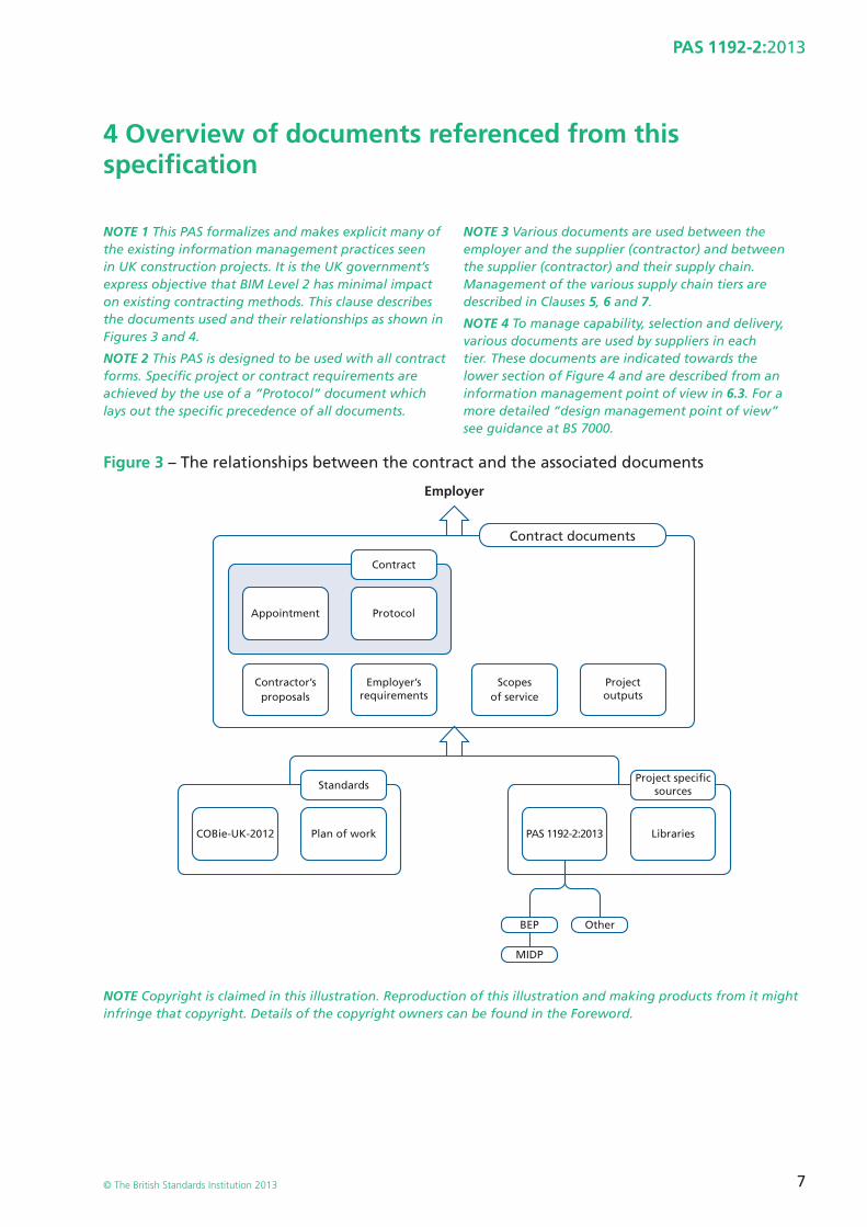
4 Overview of documents referenced from this specifi cation
NOTE 1 This PAS formalizes and makes explicit many of the existing information management practices seen in UK construction projects. It is the UK government’s express objective that BIM Level 2 has minimal impact on existing contracting methods. This clause describes the documents used and their relationships as shown in Figures 3 and 4.
NOTE 2 This PAS is designed to be used with all contract forms. Specifi c project or contract requirements are achieved by the use of a “Protocol” document which lays out the specifi c precedence of all documents.
NOTE 3 Various documents are used between the employer and the supplier (contractor) and between the supplier (contractor) and their supply chain. Management of the various supply chain tiers are described in Clauses 5, 6 and 7.
NOTE 4 To manage capability, selection and delivery, various documents are used by suppliers in each tier. These documents are indicated towards the lower section of Figure 4 and are described from an information management point of view in 6.3. For a more detailed “design management point of view” see guidance at BS 7000.
Figure 3 – The relationships between the contract and the associated documents
Employer
Plan of work PAS 1192-2:2013 LibrariesCOBie-UK-2012
StandardsProject specific
sources
BEP
MIDP
Other
Contract
Appointment
Employer’srequirements
Contractor’sproposals
Projectoutputs
Scopesof service
Protocol
Contract documents
NOTE Copyright is claimed in this illustration. Reproduction of this illustration and making products from it might infringe that copyright. Details of the copyright owners can be found in the Foreword.
8
PAS 1192-2:2013
© The British Standards Institution 2013
Figure 4 – Relationship between documents used for information management
ConstructionProgramme
MasterInformation
Delivery Plan(MIDP)
Task TeamInformation
Delivery Plan(TIDP)
Task TeamInformation
Delivery Plan(TIDP)
ResponsibilityMatrix (RM)
ProjectImplementation
Plan (PIP)
AgreedProject IT
Solutions andtools andresource
Supply ChainCapabilitySummary
(SCCS)
SupplierResource
AssessmentForm
Supplier ITAssessment
CPIx
Supplier BIMResource
AssessmentsCPIx
Supplier ITAssessment
Supplier BIMResource
Assessments
SupplierResource
AssessmentForm
Standards Methodsand Protocol (SMP)
BIMExecutionPlan (BEP)
Project Plan
NOTE Copyright is claimed in this illustration. Reproduction of this illustration and making products from it might infringe that copyright. Details of the copyright owners can be found in the Foreword.
Documents for information management shall be prepared by CPI and referred to as the Construction Project Information Xchange (CPIx):
a) the Project Implementation Plan (PIP) which is submitted pre-contract-award to convey each potential supplier’s capability related to information management;
b) the Task Information Delivery Plan (TIDP) which is submitted by each task team working on the project to set out each team’s responsibility for delivering information;
c) the Responsibility Matrix which sets out the relationship between disciplines and production of information or models;
d) the Master Information Delivery Plan (MIDP) which collates all the TIDPs against the construction programme; and
e) the BIM Execution Plan (BEP) which is submitted fi rstly pre-contract to address the issues raised in the EIR and then with more detail post-contract-award to explain the supplier’s methodology for delivering the project using BIM.
9
PAS 1192-2:2013
© The British Standards Institution 2013
5 Information delivery – Assessment and need
Figure 5 – The information delivery – Assessment and need
NEED
Employer’s InformationRequirements
(EIR)
DELIVERY
CONTRACT AWARD
Legend
PROCUREMENT
ASS
ESSM
ENT
MO
BIL
IZA
TIO
N
Mai
nta
in, R
efu
rbis
h, E
nd
of
Life
or
Bu
ild
MAINTENANCE and USE (PAS 1192-3)
STRATEGY
Opexstart
Capexstart
Master InformationDelivery Plan
(MIDP)
Green Blue
EXECUTION
BIM Execution Plan(BEP)
Informationprocess
Managementprocess
Project Information Model (PIM)
COMMON DATA ENVIRONMENT (CDE)
Asset Information Model (AIM)
Non-Graphical Data
Documentation
Info
rmat
ion
Mo
del
HA
ND
OV
ER
Graphical Model
DELIVERY
CONTRACT AWARD PROCUREMENT
MO
BIL
IZA
TIO
N
MAINTENANCE and USE (PAS 1192-3)Opexstart
Master InformationDelivery Plan
(MIDP)
EXECUTION
BIM Execution Plan(BEP)
Project Information Model (PIM)
COMMON DATA ENVIRONMENT (CDE)
Asset Information Model (AIM)
Non-Graphical Data
Documentation
Info
rmat
ion
Mo
del
HA
ND
OV
ER
Graphical Model
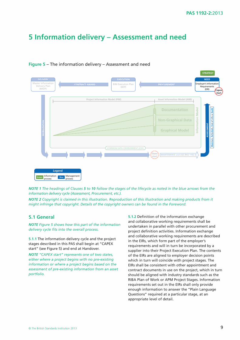
NOTE 1 The headings of Clauses 5 to 10 follow the stages of the lifecycle as noted in the blue arrows from the information delivery cycle (Assessment, Procurement, etc.).
NOTE 2 Copyright is claimed in this illustration. Reproduction of this illustration and making products from it might infringe that copyright. Details of the copyright owners can be found in the Foreword.
5.1 GeneralNOTE Figure 5 shows how this part of the information delivery cycle fi ts into the overall process.
5.1.1 The information delivery cycle and the project stages described in this PAS shall begin at “CAPEX start” (see Figure 5) and end at Handover.
NOTE “CAPEX start” represents one of two states, either where a project begins with no pre-existing information or where a project begins based on the assessment of pre-existing information from an asset portfolio.
5.1.2 Defi nition of the information exchange and collaborative working requirements shall be undertaken in parallel with other procurement and project defi nition activities. Information exchange and collaborative working requirements are described in the EIRs, which form part of the employer’s requirements and will in turn be incorporated by a supplier into their Project Execution Plan. The contents of the EIRs are aligned to employer decision points which in turn will coincide with project stages. The EIRs shall be consistent with other appointment and contract documents in use on the project, which in turn should be aligned with industry standards such as the RIBA Plan of Work or APM Project Stages. Information requirements set out in the EIRs shall only provide enough information to answer the ”Plain Language Questions” required at a particular stage, at an appropriate level of detail.
10
PAS 1192-2:2013
© The British Standards Institution 2013
NOTE 1 Where possible these will be based on standards such as the CIC Scope of Services and the various Plans of Work. Specifi c requirements of delivery and operation should be established with the employer’s advisors with a view to minimizing data to that which is needed at each stage.
NOTE 2 This document describes the generic methods for contract management, and design information production management. The detailed methods of design management and the specifi cs of the procurement strategy and documentation will need to be referenced in detail for actual delivery. These will be described in the project implementation plan (PIP) and contract documents.
NOTE 3 Responsibility for the delivery of information in principle rests with the employer who discharges accountability to the design or construction team as appropriate. Allocation of these responsibilities shall be project specifi c and documented in the contract. For further information on generic roles, refer to the various Scopes of Services such as those published by CIC.
NOTE 4 Any use of data provided in library form shall be documented in the EIR.
5.1.3 Information requirements shall be specifi c, measureable, achievable, realistic and time-bound against, for defi ned project stages and information exchanges.
NOTE These are set out in various Plans of Work including the CIC Scope of Services, to enable suppliers to determine the most effective and effi cient method of delivery.
5.1.4 The EIR shall be incorporated into the tender documentation, to enable suppliers to produce their initial BIM execution plan (BEP) – see Clause 6 – upon which their proposed approach, capability and capacity can be evaluated.
5.1.5 The employer, or the employer’s representative, shall be responsible for ensuring that information requirements are included in project contracts in such a way as to avoid duplication of responsibilities.
NOTE 1 For more information on producing the EIR see 5.3.
NOTE 2 Employers are strongly advised to assign the role of project delivery manager to one or more individuals as early as possible to develop these requirements. Under the CIC BIM Protocol (2013) the employer is obliged to appoint a party to undertake the role of Information Manager.
5.2 Origin of the employer’s information requirements (EIR)5.2.1 EIRs are produced as part of a wider set of documentation for use during project procurement and shall typically be issued as part of the employer’s requirements or tender documentation. The development of the EIR shall start either with the assessment of an existing asset, leading to the development of the employer’s need, or directly with the employer’s need if no existing asset or asset information model is to be considered.
5.2.2 Irrespective of which starting point is used in the information delivery cycle, the steps in the cycle shall be applied separately to the procurement and engagement of each tier 1 supplier required for the project as a whole.
NOTE A tier 1 supplier can provide services to the project (for example, development of the project brief, architectural services, engineering services, construction management services), or can provide goods to the project (for example, constructed assets).
5.3 Contents of the employer’s information requirements (EIR)The EIR shall include the following contents, as a minimum:
a) information management:
1) levels of detail – e.g. requirements for information submissions at defi ned project stages. This is needed to populate the Model Production and Delivery Table required under the Protocol;
2) training requirements – not likely to be mandatory;
3) planning of work and data segregation – requirements for bidders’ proposals for the management of the modelling process (e.g. model management, naming conventions, etc.);
4) co-ordination and clash detection – requirements for bidders’ proposals for the management of the co-ordination process;
5) collaboration process – requirements for bidders’ proposals for the management of the collaboration process;
6) HSE/CDM – requirements for bidders’ proposals for BIM/CDE-supported H&S/CDM management;
11
PAS 1192-2:2013
© The British Standards Institution 2013
7) a schedule of any security and integrity requirements for the project;
8) a schedule of any specifi c information to be either excluded or included from information models;
9) a schedule of any particular constraints set by the employer on the size of model fi les, the size of extranet uploads or emails, or the fi le formats that can defi ne the size of a volume;
NOTE In addition to the generic contents listed above, the EIR may also include project specifi c items such as pre-construction surveys or a requirement for the employer to receive information models describing newly-generated products and assemblies.
10) compliance plan – requirements for bidders’ proposals for the management of the co-ordination process;
11) a defi nition of any co-ordinate origin/system (3 dimensions) that the employer requires to be used to place graphical models, for example Ordnance Survey locators, geospatial and location with respect to an agreed origin;
12) a schedule of any software formats, including version numbers, that shall be used by the supply chain to deliver the project;
NOTE Public sector employers may not wish to or be able or specify software packages to be used by their suppliers, but may instead specify the formats of any outputs. Private sector employers may choose to specify software packages and/or output formats.
b) commercial management:
1) exchange of information – alignment of information exchanges, work stages, purpose and required formats;
2) client’s strategic purposes – details of the expected purposes for information provided in models (See Figure 7 at 6.1.5);
3) a schedule of any software formats, including version numbers, that shall be used by the supply chain to deliver the project;
NOTE Public sector employers may not wish to or be able or specify software packages to be used by their suppliers, but may instead specify the formats of any outputs. Private sector employers may choose to specify software packages and/or output formats.
4) an initial responsibility matrix setting out any discipline responsibilities for model or information production in line with the defi ned project stages;
5) a schedule of the standards and guidance documents used to defi ne the BIM processes and protocols to be used on the project;
6) a schedule of any changes to the standard roles, responsibilities, authorities and competences set out in the contract;
c) competence assessment:
1) details of the competence assessment which bidders must respond to;
2) changes to associated tender documentation (e.g. PQQ, PEP, tender questionnaire, tender evaluation plan);
3) BIM tender assessment details.
12
PAS 1192-2:2013
© The British Standards Institution 2013
6 Information delivery – Procurement
Figure 6 – Information delivery – Procurement
NEED
Employer’s InformationRequirements
(EIR)
DELIVERY
CONTRACT AWARD
Legend
PROCUREMENT
ASS
ESSM
ENT
MO
BIL
IZA
TIO
N
Mai
nta
in, R
efu
rbis
h, E
nd
of
Life
or
Bu
ild
MAINTENANCE and USE (PAS 1192-3)
STRATEGY
Opexstart
Capexstart
Master InformationDelivery Plan
(MIDP)
Green Blue
EXECUTION
BIM Execution Plan(BEP)
Informationprocess
Managementprocess
Project Information Model (PIM)
COMMON DATA ENVIRONMENT (CDE)
Asset Information Model (AIM)
Non-Graphical Data
Documentation
Info
rmat
ion
Mo
del
HA
ND
OV
ER
Graphical Model
NEED
Employer’s InformationRequirements
(EIR)
DELIVERY
CONTRACT AWARD
ASS
ESSM
ENT
MO
BIL
IZA
TIO
N
Mai
nta
in, R
efu
rbis
h, E
nd
of
Life
or
Bu
ild
MAINTENANCE and USE (PAS 1192-3)
STRATEGY
Opexstart
CapexCstart
Master InformationDelivery Plan
(MIDP)
Project Information Model (PIM)
COMMON DATA ENVIRONMENT (CDE)
Asset Information Model (AIM)
Non-Graphical Data
Documentation
Info
rmat
ion
Mo
del
HA
ND
OV
ER
Graphical Model
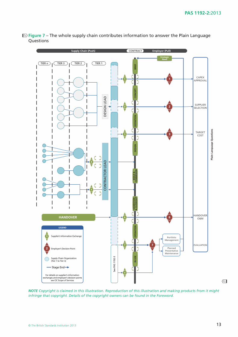
6.1 General NOTE 1 Figure 6 shows how this part of the information delivery cycle fi ts into the overall process.
NOTE 2 Copyright is claimed in this illustration. Reproduction of this illustration and making products from it might infringe that copyright. Details of the copyright owners can be found in the Foreword.
6.1.1 As part of the main contract selection process, the employer shall request in the EIRs that bidders shall submit details of their approach to project information management, suffi cient to demonstrate the supplier’s proposed approach, capability, capacity and competence to meet the EIR.
NOTE 1 The purpose of the pre-contract BEP is to demonstrate the supplier’s proposed approach, capability, capacity and competence to meet the EIR – see 6.2.1.
NOTE 2 It is likely that the BEP will be developed in two phases, pre- and post-contract award.
6.1.2 The BEP shall enable the employer to determine if the requirements within the EIR are achievable, allowing for adjustment or negotiation of the supply chain’s capabilities if necessary.
6.1.3 Post contract award, the BEP shall be re-submitted by the supplier to the employer confi rming the supply chain’s capabilities and the master information delivery plan (MIDP) – see 6.2.2 and Figure 7 (6.1.5) – and that all relevant parties have agreed and committed to the BEP.
6.1.4 This BEP shall be submitted by the supplier to the employer on behalf of the whole supply chain and shall include a summary of their capabilities and responsibilities.
6.1.5 Suppliers shall be responsible for the cascade of information through their supply chain.
NOTE 1 This is a critical activity and the employer should take steps through the bid process that details of the supplier’s information cascade process are suitable, well documented and capable of verifi cation.
NOTE 2 The rationale for employing the supply chain to provide information is to support key employer questions (the Plain Language Questions in Figure 7 (6.1.5). The relationship between these questions, the contract and the subsequent engagement of the supply chain is illustrated in Figure 7 (6.1.5).
NOTE 3 The approach that a tier 1 supplier may take to this offers much opportunity to remove waste and improve effi ciency. However, appropriate steps should be used for each supply chain tier. Guidance is available in BS 11000-1:2010.
��
��
13
PAS 1192-2:2013
© The British Standards Institution 2013
Figure 7 – The whole supply chain contributes information to answer the Plain Language Questions
1
2
1
2
6
4
6
33
5
2
5
77
n
Supply Chain (Push) Employer (Pull)
StrategicNeed
CONTRACT
Plai
n L
ang
uag
e Q
ues
tio
ns
DES
IGN
LEA
DC
ON
TRA
CTO
R L
EAD
HANDOVER
For details on supplier’s informationexchanges and employer’s decision points
see CIC Scope of Services
Employer’s Decision Point
Supplier’s Information Exchange
See
PAS
1192
-3
IN U
SEO
PER
ATI
ON
DES
IGN
DEF
INIT
ION
CO
NC
EPT
BR
IEF
HA
ND
OV
ER&
CLO
SEO
UT
BU
ILD
&C
OM
MIS
ION
LEGEND
Supply Chain Organization(Tier 1 to Tier n)
Stage End
TIER n TIER 3 TIER 2 TIER 1
CAPEXAPPROVAL
SUPPLIERSELECTION
TARGETCOST
HANDOVERO&M
EVALUATION
PortfolioManagement
PlannedPreventativeMaintenance
NOTE Copyright is claimed in this illustration. Reproduction of this illustration and making products from it might infringe that copyright. Details of the copyright owners can be found in the Foreword.
14
PAS 1192-2:2013
© The British Standards Institution 2013
6.2 Production of the pre-contract BIM execution plan (BEP)The contents of the pre-contract BEP shall consist of everything requested in the EIR plus the following information:
a) the project implementation plan (PIP) – see 6.3;
b) project goals for collaboration and information modelling;
c) major project milestones consistent with the project programme; and
d) project information model (PIM) deliverable strategy (for example the CIC Schedule).
NOTE 1 An example partial template for the preparation of the BEP is shown at http://www.cpic.org.uk.
NOTE 2 The contents of the post contract-award BEP are given at 7.2.
6.3 Project implementation plan (PIP)6.3.1 The PIP shall be submitted, as part of the initial BEP, by each organization bidding for a project.
NOTE The PIP is one of the documents used by an employer to assess the capability, competence and experience of potential suppliers bidding for a project, along with quality documentation.
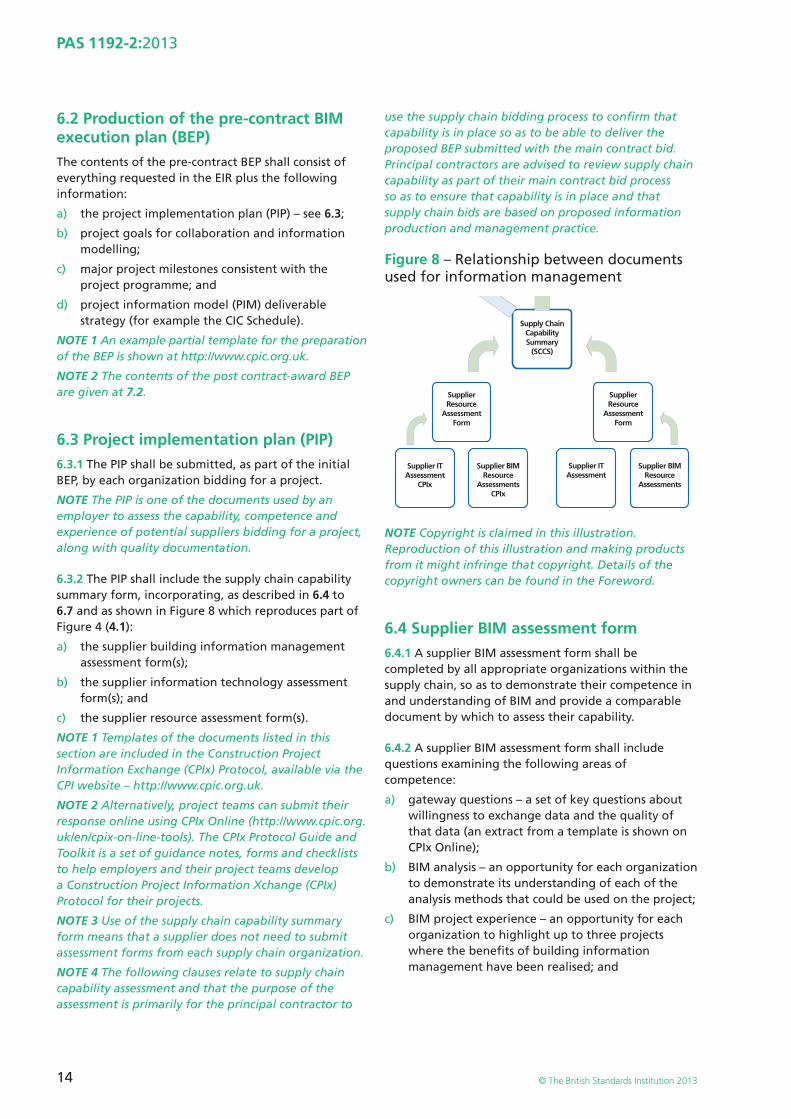
6.3.2 The PIP shall include the supply chain capability summary form, incorporating, as described in 6.4 to 6.7 and as shown in Figure 8 which reproduces part of Figure 4 (4.1):
a) the supplier building information management assessment form(s);
b) the supplier information technology assessment form(s); and
c) the supplier resource assessment form(s).
NOTE 1 Templates of the documents listed in this section are included in the Construction Project Information Exchange (CPIx) Protocol, available via the CPI website – http://www.cpic.org.uk.
NOTE 2 Alternatively, project teams can submit their response online using CPIx Online (http://www.cpic.org.uk/en/cpix-on-line-tools). The CPIx Protocol Guide and Toolkit is a set of guidance notes, forms and checklists to help employers and their project teams develop a Construction Project Information Xchange (CPIx) Protocol for their projects.
NOTE 3 Use of the supply chain capability summary form means that a supplier does not need to submit assessment forms from each supply chain organization.
NOTE 4 The following clauses relate to supply chain capability assessment and that the purpose of the assessment is primarily for the principal contractor to
use the supply chain bidding process to confi rm that capability is in place so as to be able to deliver the proposed BEP submitted with the main contract bid. Principal contractors are advised to review supply chain capability as part of their main contract bid process so as to ensure that capability is in place and that supply chain bids are based on proposed information production and management practice.
Figure 8 – Relationship between documents used for information management
Supply ChainCapabilitySummary
(SCCS)
SupplierResource
AssessmentForm
Supplier ITAssessment
CPIx
Supplier BIMResource
AssessmentsCPIx
Supplier ITAssessment
Supplier BIMResource
Assessments
SupplierResource
AssessmentForm
NOTE Copyright is claimed in this illustration. Reproduction of this illustration and making products from it might infringe that copyright. Details of the copyright owners can be found in the Foreword.
6.4 Supplier BIM assessment form6.4.1 A supplier BIM assessment form shall be completed by all appropriate organizations within the supply chain, so as to demonstrate their competence in and understanding of BIM and provide a comparable document by which to assess their capability.
6.4.2 A supplier BIM assessment form shall include questions examining the following areas of competence:
a) gateway questions – a set of key questions about willingness to exchange data and the quality of that data (an extract from a template is shown on CPIx Online);
b) BIM analysis – an opportunity for each organization to demonstrate its understanding of each of the analysis methods that could be used on the project;
c) BIM project experience – an opportunity for each organization to highlight up to three projects where the benefi ts of building information management have been realised; and
15
PAS 1192-2:2013
© The British Standards Institution 2013
d) BIM capability questionnaire – a set of questions to help the project team to identify training, coaching and support requirements.
6.5 Supplier information technology (IT) assessment form6.5.1 Completed by all appropriate organizations within the supply chain, usually in conjunction with the organization’s IT department, the supplier IT assessment form shall enable organizations to demonstrate their information exchange capability and IT maturity, and provide a meaningful method of assessing differences and similarities with the project IT systems.
6.5.2 The supplier IT assessment form shall include questions examining the following areas of capability and competence:
a) general information and company policies on information exchange – intended to show what electronic data and information the company is willing to exchange (an extract from a template is shown on CPIx Online at http://www.cpic.org.uk/en/cpix-on-line-tools); and
b) technical information on software and systems – intended to enable the company to give the project team confi dence that IT Systems and procedures are mature and robust.
6.5.3 Based on responses from the supply chain, methods of information sharing shall be reviewed and resolved by the principal supplier. Agreed solutions shall be documented by the fi nal BEP submitted to the employer.
NOTE 1 If models from one task team cannot be exchanged or read in conjunction with the models from other task teams then drawing production may be diffi cult to achieve.
NOTE 2 Problems of model, document exchange or interoperability need to be resolved as early as possible, ideally before design is started.
6.6 Supplier resource assessment formThe supplier resource assessment form shall be used to assess an organization’s current resource capability and capacity. The form shall be completed by all appropriate organizations within the delivery team as part of the sub-contract procurement process.
6.7 Supply chain capability summary formThe supply chain capability summary form shall be used to facilitate rapid comparison of the information within the team IT and resource assessment forms provided by each organization (an extract from a template is shown in CPIx Online). The form shall be completed by all appropriate organizations within the Delivery Team as part of the sub-contract procurement process.
NOTE This section is for the principal supplier to obtain enough information concerning the capability, capacity and intent of supply chain members to be assure that it has secured appropriate capability to meet the requirements of the contract and the EIRs in a timely and effi cient manner.
16
PAS 1192-2:2013
© The British Standards Institution 2013
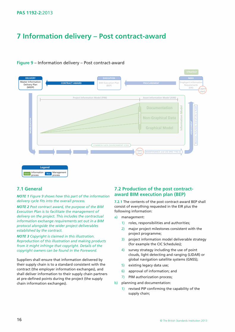
7 Information delivery – Post contract-award
Figure 9 – Information delivery – Post contract-award
NEED
Employer’s InformationRequirements
(EIR)
DELIVERY
CONTRACT AWARD
Legend
PROCUREMENT
ASS
ESSM
ENT
MO
BIL
IZA
TIO
N
Mai
nta
in, R
efu
rbis
h, E
nd
of
Life
or
Bu
ild
MAINTENANCE and USE (PAS 1192-3)
STRATEGY
Opexstart
Capexstart
Master InformationDelivery Plan
(MIDP)
Green Blue
EXECUTION
BIM Execution Plan(BEP)
Informationprocess
Managementprocess
Project Information Model (PIM)
COMMON DATA ENVIRONMENT (CDE)
Asset Information Model (AIM)
Non-Graphical Data
Documentation
Info
rmat
ion
Mo
del
HA
ND
OV
ER
Graphical Model
NEED
Employer’s InformationRequirements
(EIR)
PROCUREMENT
ASS
ESSM
ENT
MO
BIL
IZA
TIO
N
Mai
nta
in, R
efu
rbis
h, E
nd
of
Life
or
Bu
ild
MAINTENANCE and USE (PAS 1192-3)
STRATEGY
Opexstart
CapexCstart
EXECUTION
BIM Execution Plan(BEP)
Project Information Model (PIM)
COMMON DATA ENVIRONMENT (CDE)
Asset Information Model (AIM)
Non-Graphical Data
Documentation
Info
rmat
ion
Mo
del
HA
ND
OV
ER
Graphical Model
7.1 GeneralNOTE 1 Figure 9 shows how this part of the information delivery cycle fi ts into the overall process.
NOTE 2 Post contract award, the purpose of the BIM Execution Plan is to facilitate the management of delivery on the project. This includes the contractual information exchange requirements set out in a BIM protocol alongside the wider project deliverables established by the contract.
NOTE 3 Copyright is claimed in this illustration. Reproduction of this illustration and making products from it might infringe that copyright. Details of the copyright owners can be found in the Foreword.
Suppliers shall ensure that information delivered by their supply chain is to a standard consistent with the contract (the employer information exchanges), and shall deliver information to their supply chain partners at pre-defi ned points during the project (the supply chain information exchanges).
7.2 Production of the post contract-award BIM execution plan (BEP)7.2.1 The contents of the post contract-award BEP shall consist of everything requested in the EIR plus the following information:
a) management:
1) roles, responsibilities and authorities;
2) major project milestones consistent with the project programme;
3) project information model deliverable strategy (for example the CIC Schedules);
4) survey strategy including the use of point clouds, light detecting and ranging (LIDAR) or global navigation satellite systems (GNSS);
5) existing legacy data use;
6) approval of information; and
7) PIM authorization process;
b) planning and documentation:
1) revised PIP confi rming the capability of the supply chain;
17
PAS 1192-2:2013
© The British Standards Institution 2013
2) agreed project processes for collaboration and information modelling;
3) agreed matrix of responsibilities across the supply chain;
4) TIDP; and
5) MIDP;
c) the standard method and procedure:
1) the volume strategy;
2) PIM origin and orientation (which may also be geo-references to the earth’s surface using a specifi ed projection);
3) fi le naming convention;
4) layer naming convention, where used;
5) agreed construction tolerances for all disciplines;
6) drawing sheet templates;
7) annotation, dimensions, abbreviations and symbols; and
8) attribute data;
d) the IT solutions:
1) software versions;
2) exchange formats; and
3) process and data management systems.
7.3 Production of the master information delivery plan (MIDP)7.3.1 Following contract award, the project delivery manager (PDM) (see 7.5) shall initiate a project induction meeting to:
• confi rm resource availability and capability in relation to the responsibility matrix issued as part of the EIR;
• identify training and education needs, and;
• collaborate to develop the MIDP with reference to the team members’ TIDPs.
7.3.2 The MIDP shall be used by the PDM to manage the delivery of information during the project.
7.3.3 The MIDP shall list the information deliverables for the project, including but not limited to models, drawings or renditions, specifi cations, equipment schedules, room data sheets, and shall be managed via change control.
7.4 Task information delivery plan (TIDP)7.4.1 Each task team manager shall compile their own TIDP, with its milestones. These shall be used to convey the responsibility for delivery of each supplier’s information.
7.4.2 Milestones within each TIDP shall be aligned with the design and construction programmes to produce the MIDP (see 7.3).
7.4.3 For each deliverable, the TIDPs shall be used to indicate the team member responsible or to note that such responsibility has yet to be allocated.
7.4.4 The TIDPs shall be used to show how responsibility for the preparation of project documents transfers from one team member to another.
7.4.5 The TIDPs shall be used to take account of the required sequence of model preparation for any work packages used in the project.
NOTE The TIDP is part of the BEP.
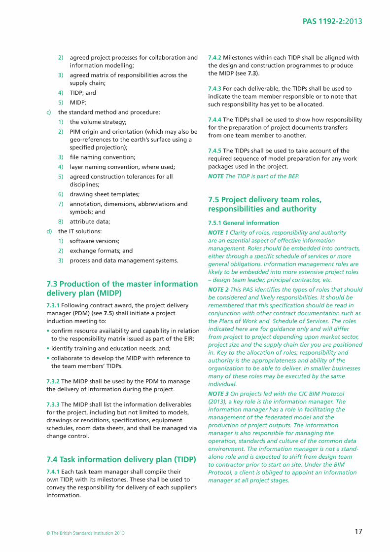
7.5 Project delivery team roles, responsibilities and authority
7.5.1 General information
NOTE 1 Clarity of roles, responsibility and authority are an essential aspect of effective information management. Roles should be embedded into contracts, either through a specifi c schedule of services or more general obligations. Information management roles are likely to be embedded into more extensive project roles – design team leader, principal contractor, etc.
NOTE 2 This PAS identifi es the types of roles that should be considered and likely responsibilities. It should be remembered that this specifi cation should be read in conjunction with other contract documentation such as the Plans of Work and Schedule of Services. The roles indicated here are for guidance only and will differ from project to project depending upon market sector, project size and the supply chain tier you are positioned in. Key to the allocation of roles, responsibility and authority is the appropriateness and ability of the organization to be able to deliver. In smaller businesses many of these roles may be executed by the same individual.
NOTE 3 On projects led with the CIC BIM Protocol (2013), a key role is the information manager. The information manager has a role in facilitating the management of the federated model and the production of project outputs. The information manager is also responsible for managing the operation, standards and culture of the common data environment. The information manager is not a stand-alone role and is expected to shift from design team to contractor prior to start on site. Under the BIM Protocol, a client is obliged to appoint an information manager at all project stages.
18
PAS 1192-2:2013
© The British Standards Institution 2013
7.5.1.1 At the induction meeting as many of the information management roles shall be identifi ed and confi rmed as possible.
NOTE This may be done through a stage-based deliverables matrix and this should be revisited during successive project stages as specialists and supply chain members join the delivery team.
7.5.1.2 The roles and responsibilities of individual team members shall be defi ned, as shall the schedule of responsibilities for deliverables of the overall team, bearing in mind that one person may deliver multiple roles.
7.5.1.3 The roles shall not be confused with the titles of the managers, which can differ from organization to organization, but the important factors are the ownership, responsibility and authority.
NOTE 1 The factors in 7.5.1.1 to 7.5.1.3 can be conveyed using the “RACI” indicators (to identify “R” the responsible party, “A” the authorizing party, “C” the contributing parties and “I” the parties to be kept informed).
NOTE 2 Information management is part of everyone’s job.
7.5.1.4 At the start of a project, roles shall be assigned and recorded and all contact information shall be listed against each role.
7.5.1.5 Roles are either per-project or per-task team and shall be responsible to one another as shown in Figure 10.
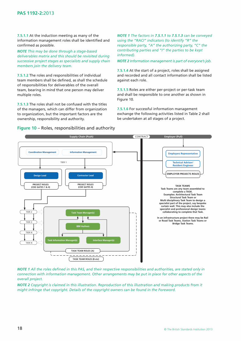
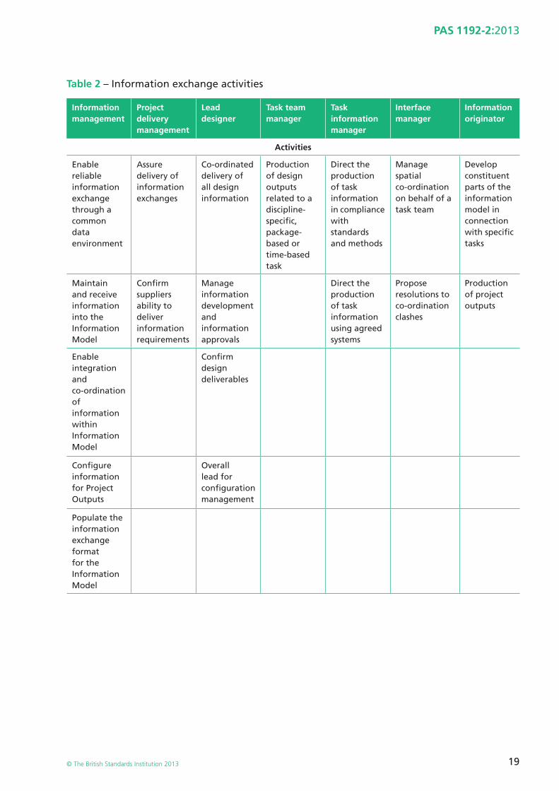
7.5.1.6 For successful information management exchange the following activities listed in Table 2 shall be undertaken at all stages of a project.
Figure 10 – Roles, responsibilities and authority
Supply Chain (Push) Employer (Pull)CONTRACT
TASK TEAMS Task Teams are any team assembled to
complete a TASK. Examples: Architectural Task Team
Structural Task Team orMulti disciplinary Task Team to design a
specialist part of the project, say bespoke curtain wall. This may also include the
specialist and professional design teams collaborating to complete that Task.
In an infrastructure project there may be Rail or Road Task Teams, Station Task Teams or
Bridge Task Teams.
Employers RepresentativeCoordination Management Information Management
Design Lead
PROJECT ROLES(CDE GATES 1 & 4)
PROJECT ROLES(CDE GATES 4)
Task Team Manager(s)
BIM Authors
Task Information Manager(s) Interface Manager(s)
TASK TEAM ROLES (B etc)
TASK TEAM ROLES (A)
Contractor Lead
TIER 1
TIER 2
TIER 3
TIER N
TIER N
EMPLOYER PROJECTS ROLES
Technical Advisor/Resident Engineer
NOTE 1 All the roles defi ned in this PAS, and their respective responsibilities and authorities, are stated only in connection with information management. Other arrangements may be put in place for other aspects of the overall project.
NOTE 2 Copyright is claimed in this illustration. Reproduction of this illustration and making products from it might infringe that copyright. Details of the copyright owners can be found in the Foreword.
19
PAS 1192-2:2013
© The British Standards Institution 2013
Table 2 – Information exchange activities
Information management
Project delivery management
Lead designer
Task team manager
Task information manager
Interface manager
Information originator
Activities
Enable reliable information exchange through a common data environment
Assure delivery of information exchanges
Co-ordinated delivery of all design information
Production of design outputs related to a discipline-specifi c, package-based or time-based task
Direct the production of task information in compliance with standards and methods
Manage spatial co-ordination on behalf of a task team
Develop constituent parts of the information model in connection with specifi c tasks
Maintain and receive information into the Information Model
Confi rm suppliers ability to deliver information requirements
Manage information development and information approvals
Direct the production of task information using agreed systems
Propose resolutions to co-ordination clashes
Production of project outputs
Enable integration and co-ordination of information within Information Model
Confi rm design deliverables
Confi gure information for Project Outputs
Overall lead for confi guration management
Populate the information exchange format for the Information Model
20
PAS 1192-2:2013
© The British Standards Institution 2013
Table 2 – Information exchange activities (continued)
Information management
Project delivery management
Lead designer
Task team manager
Task information manager
Interface manager
Information originator
Authorities
Accept reject information exchanges within the common data environment
Accept reject information exchanges within the common data environment
Confi rm status and approve information for issue within the common data environment
Issue approved information within the common data environment
Confi rm that information is suitable for issue within a common data environment
Propose resolutions to clashes
Ownership of model information
No design responsibility or right to issue instructions
Approve design changes proposed to resolve clashes
7.6 Volumes7.6.1 Where necessitated by technical limitations, the project shall be broken into a number of volumes.
NOTE 1 The selection of volumes and their allocation to project team members should be considered very carefully.
NOTE 2 The volume strategy should be owned and managed at the highest level of the project management team.
NOTE 3 Use of volumes enables concurrent work on models, information security, fi le size and other key information activities tasks to be managed effectively.
7.6.2 All members of the design team shall agree volumes as fully as possible at the start of a project and publish them as a shared document. This document shall be reviewed at successive project stages and amended and re-published as necessary.
NOTE 1 A volume may be based on important aspects of design, such as structure or cores, on specialized functions such as HVAC (heating, ventilating and air conditioning) systems or on strategic elements such as cladding.
NOTE 2 Individual design team members may require differing arrangements of volumes for their individual needs. Different sets of volumes do not have to relate to the same sub-divisions of the project. See Figure 11 (7.6.3) for a tunnel design example.
NOTE 3 Volumes are not drawing areas, and do not relate to the amount of the project shown on any given drawing.
NOTE 4 Volumes may overlap in 2-dimensional space (plan view) but they cannot overlap in their 3-dimensional space such that clash avoidance is achieved.
NOTE 5 Volumes are the responsibility of the designers.
7.6.3 If a project is divided into a number of volumes for modelling purposes, then COBie-UK-2012 fi les shall be issued from each discipline volume-specifi c model fi le at each employer information exchange and shall be combined into a single co-ordinated COBie-UK-2012 deliverable for the whole project, unless specifi ed in the EIR.
NOTE See Figure 12 for a building spatial co-ordination example.
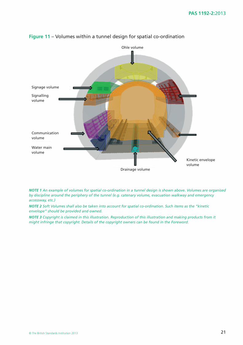
21
PAS 1192-2:2013
© The British Standards Institution 2013
Figure 11 – Volumes within a tunnel design for spatial co-ordination
NOTE 1 An example of volumes for spatial co-ordination in a tunnel design is shown above. Volumes are organised by discipline around the periphery of the tunnel (e.g. catenary volume, evacuation walkway and emergency accessway, etc.)
NOTE 2 Soft Volumes shall also be taken into account for spatial co-ordination. Such items as the “kinetic envelope” should be provided and owned.
NOTE 3 Copyright is claimed in this illustration. Reproduction of this illustration and making products from it might infringe that copyright. Details of the copyright owners can be found in the Foreword.
Ohle volume
Drainage volume
Kinetic envelope volume
Water main volume
Communication volume
Signalling volume
Signage volume
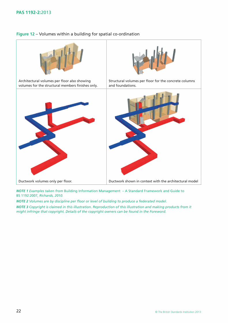
22
PAS 1192-2:2013
© The British Standards Institution 2013
Figure 12 – Volumes within a building for spatial co-ordination
Architectural volumes per fl oor also showing volumes for the structural members fi nishes only.
Structural volumes per fl oor for the concrete columns and foundations.
Ductwork volumes only per fl oor. Ductwork shown in context with the architectural model
NOTE 1 Examples taken from Building Information Management – A Standard Framework and Guide to BS 1192:2007, Richards, 2010.
NOTE 2 Volumes are by discipline per fl oor or level of building to produce a federated model.
NOTE 3 Copyright is claimed in this illustration. Reproduction of this illustration and making products from it might infringe that copyright. Details of the copyright owners can be found in the Foreword.
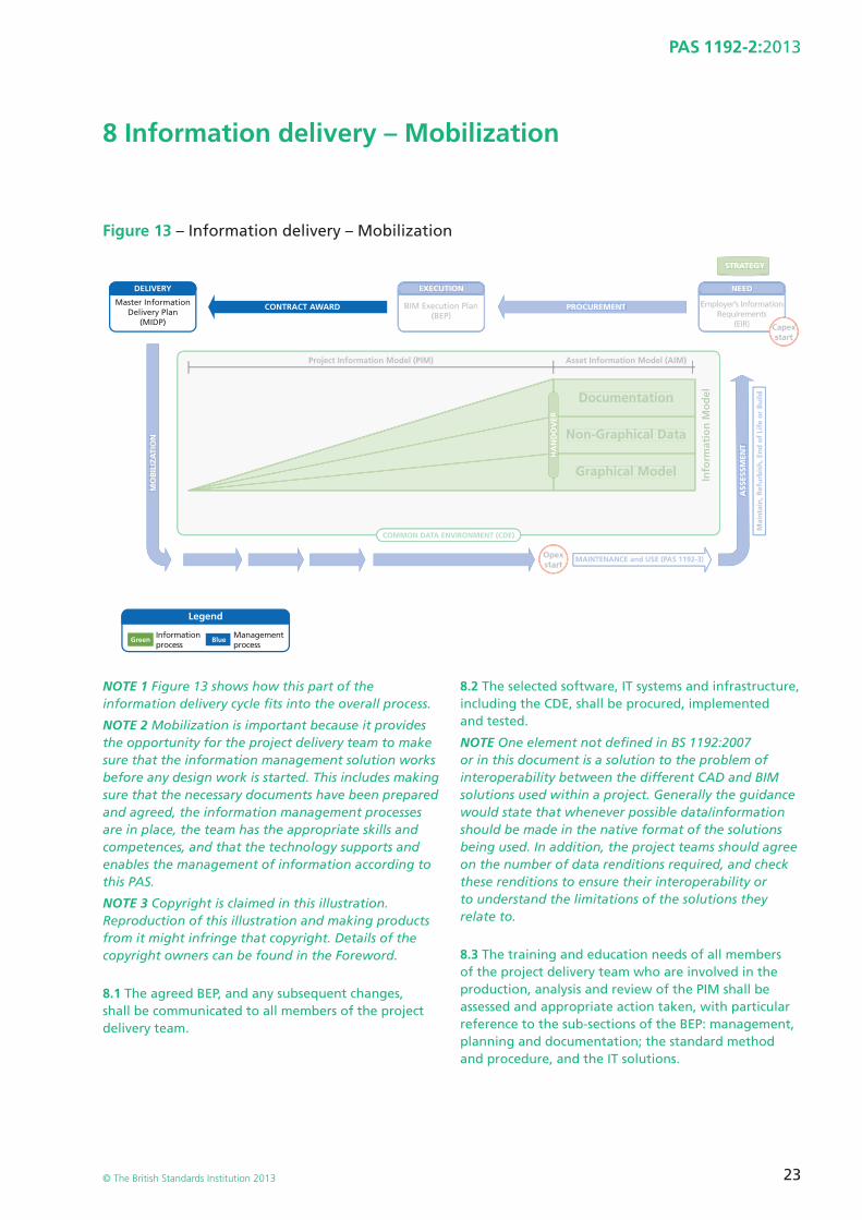
23
PAS 1192-2:2013
© The British Standards Institution 2013
8 Information delivery – Mobilization
Figure 13 – Information delivery – Mobilization
NEED
Employer’s InformationRequirements
(EIR)
DELIVERY
CONTRACT AWARD
Legend
PROCUREMENT
ASS
ESSM
ENT
MO
BIL
IZA
TIO
N
Mai
nta
in, R
efu
rbis
h, E
nd
of
Life
or
Bu
ild
MAINTENANCE and USE (PAS 1192-3)
STRATEGY
Opexstart
Capexstart
Master InformationDelivery Plan
(MIDP)
Green Blue
EXECUTION
BIM Execution Plan(BEP)
Informationprocess
Managementprocess
Project Information Model (PIM)
COMMON DATA ENVIRONMENT (CDE)
Asset Information Model (AIM)
Non-Graphical Data
Documentation
Info
rmat
ion
Mo
del
HA
ND
OV
ER
Graphical Model
NEED
Employer’s InformationRequirements
(EIR)
PROCUREMENT
ASS
ESSM
ENT
MO
BIL
IZA
TIO
N
Mai
nta
in, R
efu
rbis
h, E
nd
of
Life
or
Bu
ild
MAINTENANCE and USE (PAS 1192-3)
STRATEGY
Opexstart
CapexCstart
EXECUTION
BIM Execution Plan(BEP)
Project Information Model (PIM)
COMMON DATA ENVIRONMENT (CDE)
Asset Information Model (AIM)
Non-Graphical Data
Documentation
Info
rmat
ion
Mo
del
HA
ND
OV
ER
Graphical Model
NOTE 1 Figure 13 shows how this part of the information delivery cycle fi ts into the overall process.
NOTE 2 Mobilization is important because it provides the opportunity for the project delivery team to make sure that the information management solution works before any design work is started. This includes making sure that the necessary documents have been prepared and agreed, the information management processes are in place, the team has the appropriate skills and competences, and that the technology supports and enables the management of information according to this PAS.
NOTE 3 Copyright is claimed in this illustration. Reproduction of this illustration and making products from it might infringe that copyright. Details of the copyright owners can be found in the Foreword.
8.1 The agreed BEP, and any subsequent changes, shall be communicated to all members of the project delivery team.
8.2 The selected software, IT systems and infrastructure, including the CDE, shall be procured, implemented and tested.
NOTE One element not defi ned in BS 1192:2007 or in this document is a solution to the problem of interoperability between the different CAD and BIM solutions used within a project. Generally the guidance would state that whenever possible data/information should be made in the native format of the solutions being used. In addition, the project teams should agree on the number of data renditions required, and check these renditions to ensure their interoperability or to understand the limitations of the solutions they relate to.
8.3 The training and education needs of all members of the project delivery team who are involved in the production, analysis and review of the PIM shall be assessed and appropriate action taken, with particular reference to the sub-sections of the BEP: management, planning and documentation; the standard method and procedure, and the IT solutions.
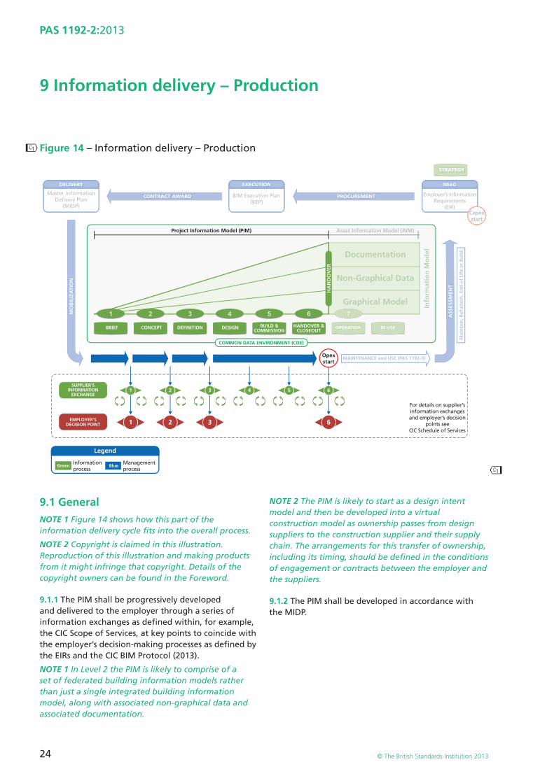
��
��
24
PAS 1192-2:2013
© The British Standards Institution 2013
9 Information delivery – Production
Figure 14 – Information delivery – Production
NEED
Employer’s InformationRequirements
(EIR)
1
7
2 3 6
1 2 3 4 5 6
DELIVERY
CONTRACT AWARD
Legend
PROCUREMENT
ASS
ESSM
ENT
MO
BIL
IZA
TIO
N
Mai
nta
in, R
efu
rbis
h, E
nd
of
Life
or
Bu
ild
MAINTENANCE and USE (PAS 1192-3)
STRATEGY
Opexstart
Capexstart
Master InformationDelivery Plan
(MIDP)
SUPPLIER’SINFORMATION
EXCHANGE
EMPLOYER’SDECISION POINT
Green Blue
EXECUTION
BIM Execution Plan(BEP)
For details on supplier’sinformation exchangesand employer’s decision
points seeCIC Schedule of Services
Informationprocess
Managementprocess
OPERATION IN USE
Asset Information Model (AIM)
Non-Graphical Data
Documentation
Info
rmat
ion
Mo
del
Graphical Model
NEED
Employer’s InformationRequirements
(EIR)
7
DELIVERY
CONTRACT AWARD PROCUREMENT
ASS
ESSM
ENT
MO
BIL
IZA
TIO
N
Mai
nta
in, R
efu
rbis
h, E
nd
of
Life
or
Bu
ild
MAINTENANCE and USE (PAS 1192-3)
STRATEGY
CapexCstart
Master InformationDelivery Plan
(MIDP)
EXECUTION
BIM Execution Plan(BEP)
OPERATION IN USE
Asset Information Model (AIM)
Non-Graphical Data
Documentation
Info
rmat
ion
Mo
del
Graphical Model
Project Information Model (PIM)
2 3 4 5 61HANDOVER &
CLOSEOUTBUILD &
COMMISSIONDESIGNBRIEF CONCEPT DEFINITION
COMMON DATA ENVIRONMENT (CDE)
HA
ND
OV
ER
9.1 GeneralNOTE 1 Figure 14 shows how this part of the information delivery cycle fi ts into the overall process.
NOTE 2 Copyright is claimed in this illustration. Reproduction of this illustration and making products from it might infringe that copyright. Details of the copyright owners can be found in the Foreword.
9.1.1 The PIM shall be progressively developed and delivered to the employer through a series of information exchanges as defi ned within, for example, the CIC Scope of Services, at key points to coincide with the employer’s decision-making processes as defi ned by the EIRs and the CIC BIM Protocol (2013).
NOTE 1 In Level 2 the PIM is likely to comprise of a set of federated building information models rather than just a single integrated building information model, along with associated non-graphical data and associated documentation.
NOTE 2 The PIM is likely to start as a design intent model and then be developed into a virtual construction model as ownership passes from design suppliers to the construction supplier and their supply chain. The arrangements for this transfer of ownership, including its timing, should be defi ned in the conditions of engagement or contracts between the employer and the suppliers.
9.1.2 The PIM shall be developed in accordance with the MIDP.
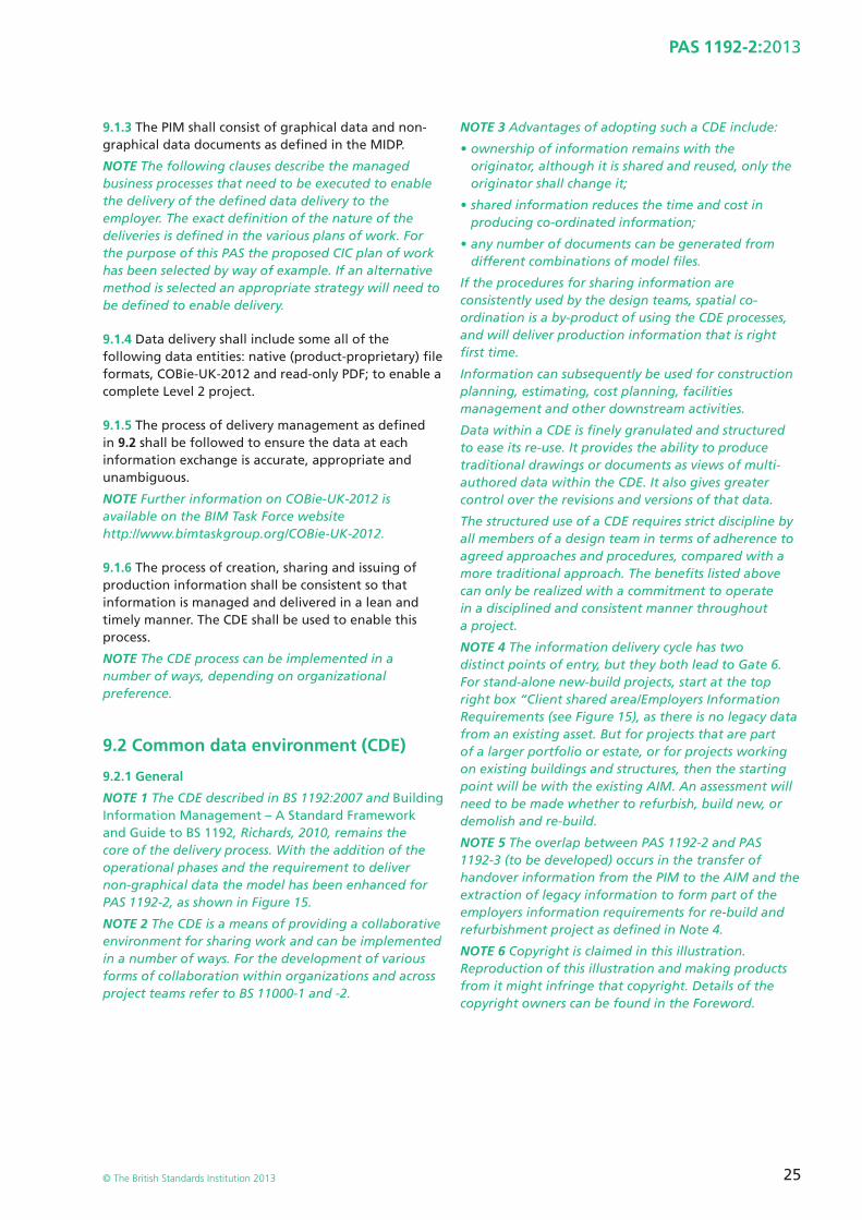
25
PAS 1192-2:2013
© The British Standards Institution 2013
9.1.3 The PIM shall consist of graphical data and non-graphical data documents as defi ned in the MIDP.
NOTE The following clauses describe the managed business processes that need to be executed to enable the delivery of the defi ned data delivery to the employer. The exact defi nition of the nature of the deliveries is defi ned in the various plans of work. For the purpose of this PAS the proposed CIC plan of work has been selected by way of example. If an alternative method is selected an appropriate strategy will need to be defi ned to enable delivery.
9.1.4 Data delivery shall include some all of the following data entities: native (product-proprietary) fi le formats, COBie-UK-2012 and read-only PDF; to enable a complete Level 2 project.
9.1.5 The process of delivery management as defi ned in 9.2 shall be followed to ensure the data at each information exchange is accurate, appropriate and unambiguous.
NOTE Further information on COBie-UK-2012 is available on the BIM Task Force website http://www.bimtaskgroup.org/COBie-UK-2012.
9.1.6 The process of creation, sharing and issuing of production information shall be consistent so that information is managed and delivered in a lean and timely manner. The CDE shall be used to enable this process.
NOTE The CDE process can be implemented in a number of ways, depending on organizational preference.
9.2 Common data environment (CDE)
9.2.1 General
NOTE 1 The CDE described in BS 1192:2007 and Building Information Management – A Standard Framework and Guide to BS 1192, Richards, 2010, remains the core of the delivery process. With the addition of the operational phases and the requirement to deliver non-graphical data the model has been enhanced for PAS 1192-2, as shown in Figure 15.
NOTE 2 The CDE is a means of providing a collaborative environment for sharing work and can be implemented in a number of ways. For the development of various forms of collaboration within organizations and across project teams refer to BS 11000-1 and -2.
NOTE 3 Advantages of adopting such a CDE include:
• ownership of information remains with the originator, although it is shared and reused, only the originator shall change it;
• shared information reduces the time and cost in producing co-ordinated information;
• any number of documents can be generated from different combinations of model fi les.
If the procedures for sharing information are consistently used by the design teams, spatial co-ordination is a by-product of using the CDE processes, and will deliver production information that is right fi rst time.
Information can subsequently be used for construction planning, estimating, cost planning, facilities management and other downstream activities.
Data within a CDE is fi nely granulated and structured to ease its re-use. It provides the ability to produce traditional drawings or documents as views of multi-authored data within the CDE. It also gives greater control over the revisions and versions of that data.
The structured use of a CDE requires strict discipline by all members of a design team in terms of adherence to agreed approaches and procedures, compared with a more traditional approach. The benefi ts listed above can only be realized with a commitment to operate in a disciplined and consistent manner throughout a project.
NOTE 4 The information delivery cycle has two distinct points of entry, but they both lead to Gate 6. For stand-alone new-build projects, start at the top right box “Client shared area/Employers Information Requirements (see Figure 15), as there is no legacy data from an existing asset. But for projects that are part of a larger portfolio or estate, or for projects working on existing buildings and structures, then the starting point will be with the existing AIM. An assessment will need to be made whether to refurbish, build new, or demolish and re-build.
NOTE 5 The overlap between PAS 1192-2 and PAS 1192-3 (to be developed) occurs in the transfer of handover information from the PIM to the AIM and the extraction of legacy information to form part of the employers information requirements for re-build and refurbishment project as defi ned in Note 4.
NOTE 6 Copyright is claimed in this illustration. Reproduction of this illustration and making products from it might infringe that copyright. Details of the copyright owners can be found in the Foreword.
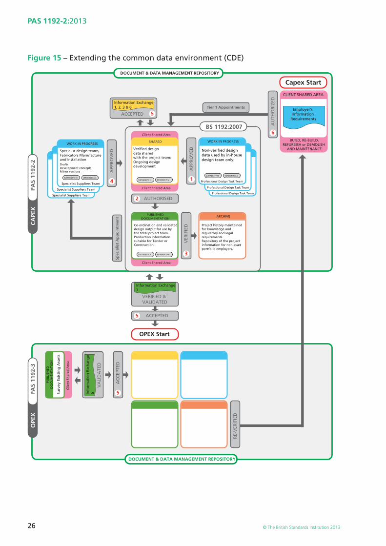
26
PAS 1192-2:2013
© The British Standards Institution 2013
Figure 15 – Extending the common data environment (CDE)
OPE
XPA
S 11
92-3
Client Shared Area
WORK IN PROGRESS
WORK IN PROGRESSWORK IN PROGRESS
WORK IN PROGRESSWORK IN PROGRESS
Client Shared Area
Client Shared Area
Client Shared Area
SHARED
Non-verified design data used by in-house design team only:
PUBLISHEDDOCUMENTATION
Co-ordination and validated design output for use by the total project team.Production information suitable for Tender or Construction :
ARCHIVE
Project history maintained for knowledge and regulatory and legal requirements. Repository of the project information for non asset portfolio employers.
WORK IN PROGRESSWORK IN PROGRESS
Specialist design teams, Fabricators Manufacture and Installation
Verified design data shared with the project team:Ongoing design developmentDrafts
Development conceptsMinor versions
Specialist Suppliers Team
Specialist Suppliers Team
Specialist Suppliers Team
SUITABILITY S0
SUITABILITY A
VERSION Pnn.nSUITABILITY S0 VERSION Pnn.n
SUITABILITY S1 REVISION Pnn
REVISION Cnn
CA
PEX
PAS
1192
-2
BS 1192:2007
ACCEPTED
AUTHORISED2
VER
IFIE
D
AU
THO
RIZ
ED
DOCUMENT & DATA MANAGEMENT REPOSITORY
APP
RO
VED
APP
RO
VED
4 1
3
6
ACCEPTED5
VERIFIED &VALIDATED
AC
CEP
TED
5
VA
LID
ATE
D
PUB
LISH
EDD
OC
UM
ENTA
TIO
N
Surv
ey E
xist
ing
Ass
ets
Clie
nt
Shar
ed A
rea
Spec
ialis
t A
pp
oin
tmen
t5
RE-
VER
IFIE
D
Information Exchange1, 2, 3 & 6
Information Exchange7
Info
rmat
ion
Exch
ange
6
Tier 1 Appointments
OPEX Start
DOCUMENT & DATA MANAGEMENT REPOSITORY
Capex Start
CLIENT SHARED AREA
Employer’s Information Requirements
BUILD, RE-BUILD,REFURBISH or DEMOLISH
AND MAINTENANCE
Professional Design Task Team
Professional Design Task Team
Professional Design Task Team
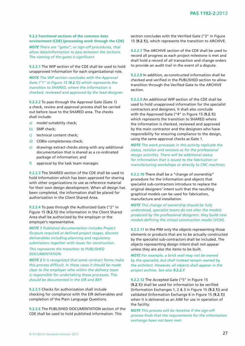
27
PAS 1192-2:2013
© The British Standards Institution 2013
9.2.2 Functional sections of the common data environment (CDE) (processing work through the CDE)
NOTE There are “gates”, or sign-off procedures, that allow data/information to pass between the sections. The naming of the gates is signifi cant.
9.2.2.1 The WIP section of the CDE shall be used to hold unapproved information for each organizational role.
NOTE The WIP section concludes with the Approval Gate (“1” in Figure 15 (9.2.1)) which represents the transition to SHARED, where the information is checked, reviewed and approved by the lead designer.
9.2.2.2 To pass through the Approval Gate (Gate 1) a check, review and approval process shall be carried out before issue to the SHARED area. The checks shall include:
a) model suitability check;
b) SMP check;
c) technical content check;
d) COBie completeness check;
e) drawings extract checks along with any additional documentation that is shared as a co-ordinated package of information; and
f) approval by the task team manager.
9.2.2.3 The SHARED section of the CDE shall be used to hold Information which has been approved for sharing with other organizations to use as reference material for their own design development. When all design has been completed, the information shall be placed for authorization in the Client Shared Area.
9.2.2.4 To pass through the Authorized Gate (“2” in Figure 15 (9.2.1)) the information in the Client Shared Area shall be authorized by the employer or the employer’s representative.
NOTE 1 Published documentation includes Project Outputs required at defi ned project stages, discrete deliverables including planning and regulatory submissions together with issues for construction.
This represents the transition to PUBLISHED DOCUMENTATION.
NOTE 2 It is recognized that some contract forms make this process diffi cult. In these cases it should be made clear to the employer who within the delivery team is responsible for undertaking these processes. This should be documented in the EIR and BEP.
9.2.2.5 Checks for authorization shall include checking for compliance with the EIR deliverables and completion of the Plain Language Questions.
9.2.2.6 The PUBLISHED DOCUMENTATION section of the CDE shall be used to hold published information. This
section concludes with the Verifi ed Gate (“3” in Figure 15 (9.2.1)), which represents the transition to ARCHIVE.
9.2.2.7 The ARCHIVE section of the CDE shall be used to record all progress as each project milestone is met and shall hold a record of all transaction and change orders to provide an audit trail in the event of a dispute.
9.2.2.8 In addition, as-constructed information shall be checked and verifi ed in the PUBLISHED section to allow transition through the Verifi ed Gate to the ARCHIVE section.
9.2.2.9 An additional WIP section of the CDE shall be used to hold unapproved information for the specialist contractors and designers. It shall also conclude with the Approved Gate (“4” in Figure 15 (9.2.1)) which represents the transition to SHARED where the information is checked, reviewed and approved by the main contractor and the designers who have responsibility for ensuring compliance to the design, using the same approval checks as Gate 1.
NOTE The work processes in this activity replicate the status, revision and versions as for the professional design activities. There will be additional status for information that is issued to the fabrication or manufacturing workshops or directly to CNC machines.
9.2.2.10 There shall be a “change of ownership” procedure for the information and objects that specialist sub-contractors introduce to replace the original designers’ intent such that the resulting graphical models can be used for fabrication, manufacture and installation.
NOTE This change of ownership should be fully understood, specialist teams do not alter the models produced by the professional designers: they build new models defi ning the virtual construction model (VCM).
9.2.2.11 In the PIM only the objects representing those elements or products that are to be actually constructed by the specialist sub-contractors shall be included. The objects representing design intent shall not appear unless they are also the items to be built.
NOTE For example, a brick wall may not be owned by the specialist, but shall instead remain owned by the architect. However, all objects shall appear in the project archive. See also 9.2.2.7.
9.2.2.12 The Accepted Gate (“5” in Figure 15 (9.2.1)) shall be used for information to be verifi ed (Information Exchanges 1, 2 & 3 in Figure 15 (9.2.1)) and validated (Information Exchange 6 in Figure 15 (9.2.1)) when it is delivered as an AIM for use in operation of the facility.
NOTE This process will be iterative if the sign-off process fi nds that the requirements for the information exchange have not been met.
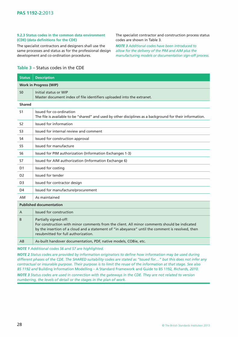
28
PAS 1192-2:2013
© The British Standards Institution 2013
9.2.3 Status codes in the common data environment (CDE) (data defi nitions for the CDE)
The specialist contractors and designers shall use the same processes and status as for the professional design development and co-ordination procedures.
The specialist contractor and construction process status codes are shown in Table 3.
NOTE 3 Additional codes have been introduced to allow for the delivery of the PIM and AIM plus the manufacturing models or documentation sign-off process.
Table 3 – Status codes in the CDE
Status Description
Work in Progress (WIP)
S0 Initial status or WIPMaster document index of fi le identifi ers uploaded into the extranet.
Shared
S1 Issued for co-ordinationThe fi le is available to be “shared” and used by other disciplines as a background for their information.
S2 Issued for information
S3 Issued for internal review and comment
S4 Issued for construction approval
S5 Issued for manufacture
S6 Issued for PIM authorization (Information Exchanges 1-3)
S7 Issued for AIM authorization (Information Exchange 6)
D1 Issued for costing
D2 Issued for tender
D3 Issued for contractor design
D4 Issued for manufacture/procurement
AM As maintained
Published documentation
A Issued for construction
B Partially signed-off: For construction with minor comments from the client. All minor comments should be indicated by the insertion of a cloud and a statement of “in abeyance” until the comment is resolved, then resubmitted for full authorization.
AB As-built handover documentation, PDF, native models, COBie, etc.
NOTE 1 Additional codes S6 and S7 are highlighted.
NOTE 2 Status codes are provided by information originators to defi ne how information may be used during different phases of the CDE. The SHARED suitability codes are stated as “Issued for…” but this does not infer any contractual or insurable purpose. Their purpose is to limit the reuse of the information at that stage. See also BS 1192 and Building Information Modelling – A Standard Framework and Guide to BS 1192, Richards, 2010.
NOTE 3 Status codes are used in connection with the gateways in the CDE. They are not related to version numbering, the levels of detail or the stages in the plan of work.
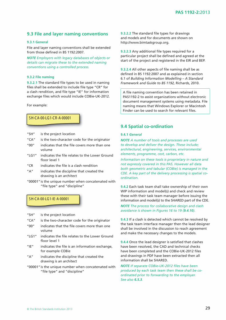
29
PAS 1192-2:2013
© The British Standards Institution 2013
9.3 File and layer naming conventions
9.3.1 General
File and layer naming conventions shall be extended from those defi ned in BS 1192:2007.
NOTE Employers with legacy databases of objects or details can migrate these to the extended naming conventions using a controlled process.
9.3.2 File naming
9.3.2.1 The standard fi le types to be used in naming fi les shall be extended to include fi le type “CR” for a clash rendition, and fi le type “IE” for information exchange fi les which would include COBie-UK-2012.
For example:
S H-C A-00-LG 1-C R -A-00001
“S H” is the project location
“CA” is the two-character code for the originator
“00” indicates that the fi le covers more than one volume
“LG1” indicates the fi le relates to the Lower Ground fl oor level 1
“CR indicates the fi le is a clash rendition
“A” indicates the discipline that created the drawing is an architect
“00001” is the unique number when concatenated with “fi le type” and “discipline”
S H-C A-00-LG 1-IE -A-00001
“SH ” is the project location
“CA” is the two-character code for the originator
“00” indicates that the fi le covers more than one volume
“LG1” indicates the fi le relates to the Lower Ground fl oor level 1
“IE” indicates the fi le is an information exchange, for example COBie
“A” indicates the discipline that created the drawing is an architect
“00001” is the unique number when concatenated with “fi le type” and “discipline”
9.3.2.2 The standard fi le types for drawings and models and for documents are shown on http://www.bimtaskgroup.org.
9.3.2.3 Any additional fi le types required for a particular project shall be defi ned and agreed at the start of the project and registered in the EIR and BEP.
9.3.2.4 All other aspects of fi le naming shall be as defi ned in BS 1192:2007 and as explained in section 6.1 of Building Information Modelling – A Standard Framework and Guide to BS 1192, Richards, 2010.
A fi le naming convention has been retained in PAS1192-2 to assist organizations without electronic document management systems using metadata. File naming means that Windows Explorer or Macintosh Finder can be used to search for relevant fi les.
9.4 Spatial co-ordination
9.4.1 General
NOTE A number of tools and processes are used to develop and deliver the design. These include; architectural, engineering, services, environmental elements, programme, cost, carbon, etc.
Information on these tools is proprietary in nature and not expressly covered in this PAS. However all data both geometric and tabular (COBie) is managed in the CDE. A key part of the delivery processing is spatial co-ordination.
9.4.2 Each task team shall take ownership of their own WIP information and model(s) and check and review these with their task team manager before issuing the information and model(s) to the SHARED part of the CDE.
NOTE The process for collaborative design and clash avoidance is shown in Figures 16 to 19 (9.4.10).
9.4.3 If a clash is detected which cannot be resolved by the task team interface manager then the lead designer shall be involved in the discussion to reach agreement and make the necessary changes to the models.
9.4.4 Once the lead designer is satisfi ed that clashes have been resolved, the CAD and technical checks have been completed and the COBie-UK-2012 fi les and drawings in PDF have been extracted then all information shall be SHARED.
NOTE If separate COBie-UK-2012 fi les have been produced by each task team then these shall be co-ordinated prior to forwarding to the employer. See also 6.5.3.
30
PAS 1192-2:2013
© The British Standards Institution 2013
9.4.5 Revision numbering and version control shall be kept in step between any model and its related information, whenever either the model or the information is changed.
This is explained in BS1192:2007 and Building Information Modelling – A Standard Framework and Guide to BS 1192, Richards, 2010.
Revision numbers in WIP are P1.1, P1.2 … P1.n, P2.1, P2.2 … P2.n, etc. The relevant status code is S0. Revision numbers in SHARED are P1, P2, P3, etc. The relevant status codes are S1-S7, D1-D4 and AM. Revision numbers in PUBLISHED are C1, C2, C3 etc. The relevant status codes are A, B and AB.
Version numbers are subdivisions of a revision.
9.4.6 Specialist design, manufacturing and fabrication models shall be reviewed for clashes in the same way as described in Figures 16 to 19 (9.4.10).
Clash checking shall be carried out during design, with particular focus on hard clashes and construction tolerances.
9.4.7 Clash avoidance/checking shall be carried out during specialist design and development of the virtual construction model, with particular focus on soft clashes (for example, positioning of insulation around ductwork and pipework) and proximity checks (for example, the placement of oxygen and other gases or fl ammable substances in hospitals).
NOTE Checks can also be made for health and safety issues (for example trip hazards from low-level pipework and reach hazards relating to positioning of equipment such as valves).
9.4.8 Clash avoidance/checking shall continue during the construction process as the models are updated with as-constructed information and checked against the construction tolerances specifi ed in the contract.
9.4.9 Construction or manufacturing defects or deviation out of tolerance shall be measured and the models updated within a time agreed across the project (e.g. 24 or 48 hours) so that impact on following trades can be checked and appropriate decisions can be taken. Responsibility for this activity should be defi ned in the PEP.
NOTE 1 For example, if foundations have been cast too high or too low then changes may be required to the structural steel frame before frame elements are fabricated to avoid site re-work and delays.
NOTE 2 If the actual construction is within tolerance then no report needs to be made to update the model.
NOTE 3 This clause does not mean that the whole project has to be continually resurveyed but the check is to see if the constructed items are as defi ned, in terms of size and position, that would normally be carried out during construction.
9.4.10 To achieve spatial co-ordination when the software solutions of the individual teams are incapable of a reasonable level of interoperability then clash renditions shall be used. The clash renditions shall be made in the format of the viewing tool that has been chosen for the project. The clash rendition for each model for each discipline shall be issued to the SHARED area along with all other deliverables.
NOTE 1 The individual SHARED models may be combined for design review by the lead designer. Design decisions or clashes that cannot be resolved by the interface managers can then be reviewed and resolved.
NOTE 2 Clash avoidance and detection is continuous throughout project delivery.
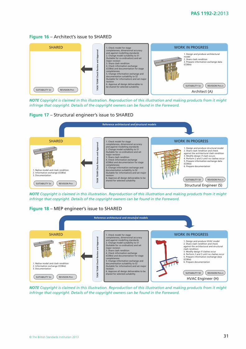
31
PAS 1192-2:2013
© The British Standards Institution 2013
Figure 16 – Architect’s issue to SHARED
SHARED
SUITABILITY Sn REVISION Pnn
SUITABILITY Sn REVISION Pnn.n
1. Check model for stagecompleteness, dimensional accuracyand against modelling standards2. Change model suitability to S1(Suitable for co-ordination) and setmajor revision3. Share clash rendition4. Check information exchange(COBie) and documentation for stagecompleteness5. Change information exchange anddocumentation suitability to S2(Suitable for information) and set majorrevision6. Approve all design deliverables tobe shared for selected suitability
Architect (A)
WORK IN PROGRESS
1. Design and produce architecturalmodel2. Share clash rendition3. Prepare information exchange data(COBie)
TASK
TEA
M C
hec
k R
evie
w a
nd
Ap
pro
val
NOTE Copyright is claimed in this illustration. Reproduction of this illustration and making products from it might infringe that copyright. Details of the copyright owners can be found in the Foreword.
Figure 17 – Structural engineer’s issue to SHARED
1. Native model and clash rendition2. Information exchange (COBie)3. Documentation
SHARED 1. Check model for stagecompleteness, dimensional accuracyand against modelling standards2. Change model suitability to S1(Suitable for co-ordination) and setmajor revision3. Share clash rendition4. Check information exchange(COBie) and documentation for stagecompleteness5. Change information exchange anddocumentation suitability to S2(Suitable for information) and set majorrevision6. Approve all design deliverables to beshared for selected suitability
Reference architectural and structural models
Structural Engineer (S)
1. Design and produce structural model2. Share clash rendition and checkagainst the architectural clash rendition3. Modify design if clash occurs4. Perform 2 and 3 until no clashes occur5. Prepare information exchange data(COBie)6. Prepare documentation
SUITABILITY Sn REVISION Pnn
SUITABILITY S0 REVISION Pnn.n
WORK IN PROGRESS
TASK
TEA
M C
hec
k R
evie
w a
nd
Ap
pro
val
NOTE Copyright is claimed in this illustration. Reproduction of this illustration and making products from it might infringe that copyright. Details of the copyright owners can be found in the Foreword.
Figure 18 – MEP engineer’s issue to SHARED
SUITABILITY Sn REVISION Pnn
1. Native model and clash rendition2. Information exchange (COBie)3. Documentation
SHARED 1. Check model for stagecompleteness, dimensional accuracyand against modelling standards2. Change model suitability to S1(Suitable for co-ordination) and setmajor revision3. Share clash rendition4. Check information exchange(COBie) and documentation for stagecompleteness5. Change information exchange anddocumentation suitability to S2(Suitable for information) and set majorrevision6. Approve all design deliverables to beshared for selected suitability
Reference architectural and structural models
HVAC Engineer (H)
WORK IN PROGRESS
1. Design and produce HVAC model2. Share clash rendition and checkagainst the architectural and structuralclash rendition3. Modify design if clashes occur4. Perform 2 and 3 until no clashes occur5. Prepare information exchange data(COBie)6. Prepare documentation
TASK
TEA
M C
hec
k R
evie
w a
nd
Ap
pro
val
SUITABILITY S0 REVISION Pnn.n
NOTE Copyright is claimed in this illustration. Reproduction of this illustration and making products from it might infringe that copyright. Details of the copyright owners can be found in the Foreword.
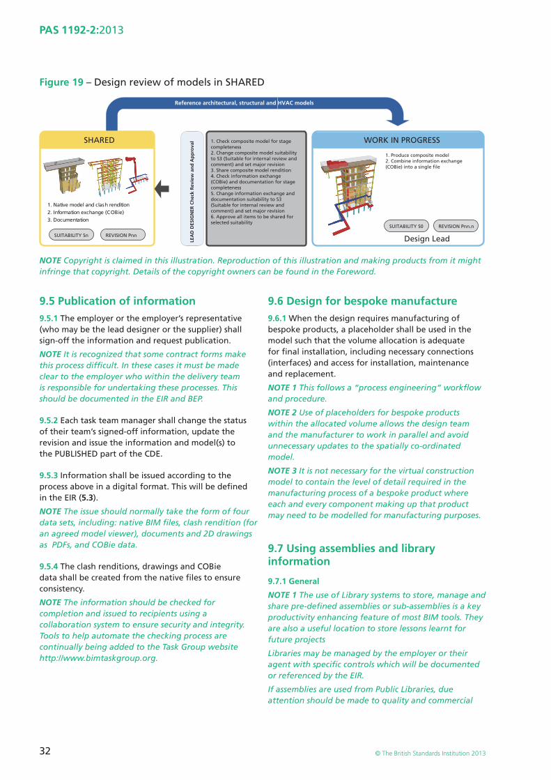
32
PAS 1192-2:2013
© The British Standards Institution 2013
Figure 19 – Design review of models in SHARED
SUITABILITY Sn REVISION Pnn
SUITABILITY S0 REVISION Pnn.n
1. Native model and clash rendition2. Information exchange (COBie)3. Documentation
SHARED 1. Check composite model for stagecompleteness2. Change composite model suitabilityto S3 (Suitable for internal review andcomment) and set major revision3. Share composite model rendition4. Check information exchange(COBie) and documentation for stagecompleteness5. Change information exchange anddocumentation suitability to S3(Suitable for internal review andcomment) and set major revision6. Approve all items to be shared for selected suitability
Reference architectural, structural and HVAC models
Design Lead
WORK IN PROGRESS
1. Produce composite model2. Combine information exchange(COBie) into a single file
LEA
D D
ESIG
NER
Ch
eck
Rev
iew
an
d A
pp
rova
l
NOTE Copyright is claimed in this illustration. Reproduction of this illustration and making products from it might infringe that copyright. Details of the copyright owners can be found in the Foreword.
9.5 Publication of information9.5.1 The employer or the employer’s representative (who may be the lead designer or the supplier) shall sign-off the information and request publication.
NOTE It is recognized that some contract forms make this process diffi cult. In these cases it must be made clear to the employer who within the delivery team is responsible for undertaking these processes. This should be documented in the EIR and BEP.
9.5.2 Each task team manager shall change the status of their team’s signed-off information, update the revision and issue the information and model(s) to the PUBLISHED part of the CDE.
9.5.3 Information shall be issued according to the process above in a digital format. This will be defi ned in the EIR (5.3).
NOTE The issue should normally take the form of four data sets, including: native BIM fi les, clash rendition (for an agreed model viewer), documents and 2D drawings as PDFs, and COBie data.
9.5.4 The clash renditions, drawings and COBie data shall be created from the native fi les to ensure consistency.
NOTE The information should be checked for completion and issued to recipients using a collaboration system to ensure security and integrity. Tools to help automate the checking process are continually being added to the Task Group website http://www.bimtaskgroup.org.
9.6 Design for bespoke manufacture9.6.1 When the design requires manufacturing of bespoke products, a placeholder shall be used in the model such that the volume allocation is adequate for fi nal installation, including necessary connections (interfaces) and access for installation, maintenance and replacement.
NOTE 1 This follows a “process engineering” workfl ow and procedure.
NOTE 2 Use of placeholders for bespoke products within the allocated volume allows the design team and the manufacturer to work in parallel and avoid unnecessary updates to the spatially co-ordinated model.
NOTE 3 It is not necessary for the virtual construction model to contain the level of detail required in the manufacturing process of a bespoke product where each and every component making up that product may need to be modelled for manufacturing purposes.
9.7 Using assemblies and library information
9.7.1 General
NOTE 1 The use of Library systems to store, manage and share pre-defi ned assemblies or sub-assemblies is a key productivity enhancing feature of most BIM tools. They are also a useful location to store lessons learnt for future projects
Libraries may be managed by the employer or their agent with specifi c controls which will be documented or referenced by the EIR.
If assemblies are used from Public Libraries, due attention should be made to quality and commercial
33
PAS 1192-2:2013
© The British Standards Institution 2013
checks especially licences to use and reuse information. Under the CIC BIM Protocol (2013), originators provide assurance that all assemblies within a model are licensed for use in connection with the project
NOTE 2 The use of library systems to store, manage and share pre-defi ned assemblies or sub-assemblies is a key productivity enhancing feature of most BIM tools. They are also a useful location to store lessons learnt for future projects.
Libraries may be managed by the employer or their representative with specifi c controls which will be documented or referenced by the EIR.
NOTE 3 The creation and management of assemblies, components and materials are documented elsewhere, including at http://www.bimtaskgroup.org.
9.8 Levels of model defi nition9.8.1 The minimum level of detail needed by the team or the employer for each model’s purpose shall be defi ned.
NOTE 1 Key to the success of information management is clear defi nition of requirements as defi ned by the information exchanges and including COBie and geometry.
NOTE 2 It is wasteful for the supply chain to deliver a greater level of detail than is needed which may also overload the IT systems and networks available.
9.8.2 The level of model defi nition required in a model at an information exchange shall be defi ned in the EIR and the CIC BIM Protocol (2013). The level of graphical information and data to be delivered at each information exchange will be defi ned with reference to industry standards.
9.8.3 The levels of model defi nition shall be articulated in the BEP and need to be fully understood by all relevant members of the project team.
9.8.4 Levels of model defi nition shall conform to:
a) the EIR;
b) the scope of work set out by the CIC Scope of Services, for example, related to the project stages; and
c) the Uniclass classifi cation tables regarding the relationship of systems, products and elements with the specifi cation and the cost plan.
NOTE The Uniclass classifi cation tables shall defi ne the progressive maturity of the model from outline, spaces and volumes, to design elements and fi nally to products. See Table 3 (9.2.3) for cross-reference of CIC stages and Uniclass classifi cation tables.
9.9 Levels of model detail and model informationNOTE The levels of model detail and model information shown in Figure 20 (9.9.7) are derived from the BIM Task Group website: http://www.bimtaskgroup.org.
9.9.1 Brief
NOTE At briefi ng stage, the graphical model will either not exist or will inherit information from the AIM (for work on existing buildings and structures).
9.9.2 Concept
NOTE At concept design stage the graphical design may only show a massing diagram or specify a symbol in 2D to represent a generic element. See BS 8541-2.
9.9.3 Design
At design stage the objects shall be represented in 3D with the specifi cation attached.
NOTE 1 See BS 8541-1, BS 8541-3 and BS 8541-4.
NOTE 2 The level of detail should as a minimum represent the space allocation for the product’s access space for maintenance, installation and replacement space in addition to its operational space. For example, the space required to turn on or turn off valves.
9.9.4 Defi nition
At defi nition stage the object shall be based on a generic representation of the element.
NOTE The specifi cation properties and attributes from design allow selection of a manufacturer’s product, unless the product is nominated, free issue or already selected.
9.9.5 Build and commission
At build and commission stage any generic object shall be replaced with the object procured from the manufacturer. Any essential information to be retained shall be reattached or relinked to the replacement object.
NOTE 1 Inheritance of information is a complex issue and should be well understood and the solution tested at mobilization.
NOTE 2 The selection of the product should give further detail about fl anges and connections so that fi nal positioning of pipework and ductwork can be defi ned.
NOTE 3 Although minimum levels of graphical detail can be specifi ed at each design stage, care should be taken that adequate detail is provided to convey design intent and installation requirements. See Design Framework for Building Services, Churcher, 2012,
34
PAS 1192-2:2013
© The British Standards Institution 2013
NOTE 4 for an example of the full process relating to building services.
9.9.6 Handover and close-out
At the handover and close-out stage all necessary information about the product shall be included in the handover document and attached to the commissioning and handover documentation. The as-constructed model shall represent the as-constructed project in content and dimensional accuracy.
NOTE In addition is all the manufacturer’s maintenance and operation documentation, commissioning records, health and safety requirements, the fi nal COBie information exchange, as-built models in native format and all relevant documentation.
9.9.7 Operation and in-use
At the operation stage, the performance of the project shall be verifi ed against the EIR and the brief. If the specifi cation is not met and changes are necessary then objects that have been changed or replaced with different equipment shall be updated accordingly.
At the in-use stage, the object’s information shall be updated with any supplementary information such as maintenance records or replacement dates, and objects that have been changed or replaced with different equipment shall be updated accordingly.
��
35
PAS 1192-2:2013
© The British Standards Institution 2013
Fig
ure
20
– Le
vels
of
mo
del
defi
nit
ion
fo
r b
uild
ing
an
d in
fras
tru
ctu
re p
roje
cts
Stag
e n
um
ber
Mo
del
nam
e
1 Bri
ef
2 Co
nce
pt
3 Defi
nit
ion
4 Des
ign
5 Bu
ild a
nd
co
mm
issi
on
6 Han
do
ver
and
cl
ose
ou
t
7 Op
erat
ion
Syst
ems
to b
e co
ver e
dN
/AA
llA
llA
llA
llA
llA
ll
Gra
ph
ical
ill
ust
rati
on
(b
uild
ing
p
roje
ct)
Gra
ph
ical
ill
ust
rati
on
(i
nfr
astr
uct
ure
p
roje
ct)
Wh
at t
he
mo
del
can
be
relie
d u
po
n f
or
Mo
del
in
form
atio
n
com
mu
nic
atin
g
the
bri
ef,
per
form
ance
re
qu
irem
ents
, p
erfo
rman
ce
ben
chm
arks
an
d
site
co
nst
rain
ts
Mo
del
s w
hic
h
com
mu
nic
ate
the
init
ial r
esp
on
se
to t
he
bri
ef,
aest
het
ic in
ten
t an
d o
utl
ine
per
form
ance
re
qu
irem
ents
. Th
e m
od
el c
an
be
use
d f
or
earl
y d
esig
n
dev
elo
pm
ent,
an
alys
is a
nd
co
-ord
inat
ion
. M
od
el c
on
ten
t is
no
t fi
xed
an
d
may
be
sub
ject
to
fu
rth
er d
esig
n
dev
elo
pm
ent.
Th
e m
od
el c
an
be
use
d f
or
co-o
rdin
atio
n,
seq
uen
cin
g
and
est
imat
ing
p
urp
ose
s
A d
imen
sio
nal
ly
corr
ect
and
co
-ord
inat
ed m
od
el
wh
ich
co
mm
un
icat
es
the
resp
on
se t
o
the
bri
ef, a
esth
etic
in
ten
t an
d s
om
e p
erfo
rman
ce
info
rmat
ion
th
at
can
be
use
d f
or
anal
ysis
, des
ign
d
evel
op
men
t an
d
earl
y co
ntr
acto
r en
gag
emen
t. T
he
mo
del
can
be
use
d
for
co-o
rdin
atio
n,
seq
uen
cin
g a
nd
es
tim
atin
g p
urp
ose
s in
clu
din
g t
he
agre
emen
t o
f a
fi rs
t st
age
targ
et p
rice
A d
imen
sio
nal
ly
corr
ect
and
co
-o
rdin
ated
mo
del
th
at c
an b
e u
sed
to
ve
rify
co
mp
lian
ce
wit
h r
egu
lato
ry
req
uir
emen
ts.
The
mo
del
can
b
e u
sed
as
the
star
t p
oin
t fo
r th
e in
corp
ora
tio
n o
f sp
ecia
list
con
trac
tor
des
ign
mo
del
s an
d c
an in
clu
de
info
rmat
ion
th
at c
an b
e u
sed
fo
r fa
bri
cati
on
, co
-ord
inat
ion
, se
qu
enci
ng
an
d e
stim
atin
g
pu
rpo
ses,
incl
ud
ing
th
e ag
reem
ent
of
a ta
rget
pri
ce/
gu
aran
teed
m
axim
um
pri
ce
An
acc
ura
te m
od
el o
f th
e as
set
bef
ore
an
d
du
rin
g c
on
stru
ctio
n
inco
rpo
rati
ng
co
-ord
inat
ed
spec
ialis
t su
b-
con
trac
t d
esig
n
mo
del
s an
d
asso
ciat
ed m
od
el
attr
ibu
tes.
Th
e m
od
el c
an b
e u
sed
fo
r se
qu
enci
ng
of
inst
alla
tio
n a
nd
ca
ptu
re o
f as
-in
stal
led
info
rmat
ion
An
acc
ura
te
reco
rd o
f th
e as
set
as a
co
nst
ruct
ed
at h
and
ove
r, in
clu
din
g a
ll in
form
atio
n
req
uir
ed f
or
op
erat
ion
an
d
mai
nte
nan
ce
An
up
dat
ed r
eco
rd
of
the
asse
t at
a
fi xe
d p
oin
t in
tim
e in
corp
ora
tin
g a
ny
maj
or
chan
ges
m
ade
sin
ce
han
do
ver,
incl
ud
ing
p
erfo
rman
ce a
nd
co
nd
itio
n d
ata
and
al
l in
form
atio
n
req
uir
ed f
or
op
erat
ion
an
d
mai
nte
nan
ce
The
full
con
ten
t w
ill
be
avai
lab
le in
th
e ye
t to
be
pu
blis
hed
PA
S 11
92-3
36
PAS 1192-2:2013
© The British Standards Institution 2013
Fig
ure
20
– Le
vels
of
mo
del
defi
nit
ion
fo
r b
uild
ing
an
d in
fras
tru
ctu
re p
roje
cts
(co
nti
nu
ed)
Stag
e n
um
ber
Mo
del
nam
e
1 Bri
ef
2 Co
nce
pt
3 Defi
nit
ion
4 Des
ign
5 Bu
ild a
nd
co
mm
issi
on
6 Han
do
ver
and
cl
ose
ou
t
7 Op
erat
ion
Ou
tpu
tPr
oje
ct b
rief
an
d
pro
cure
men
t st
rate
gy
Refi
ned
pro
ject
b
rief
an
d c
on
cep
t ap
pro
val
Ap
pro
val o
f co
-ord
inat
ed
dev
elo
ped
des
ign
Inte
gra
ted
p
rod
uct
ion
in
form
atio
n
Inte
gra
ted
p
rod
uct
ion
in
form
atio
n.
Co
mp
lete
fa
bri
cati
on
an
d
man
ufa
ctu
rin
g
det
ails
, sy
stem
an
d
elem
ent
veri
fi ca
tio
n,
op
erat
ion
an
d
mai
nte
nan
ce
info
rmat
ion
Mo
dif
y to
re
pre
sen
t as
in
stal
led
mo
del
wit
h a
ll as
soci
ated
d
ata
refe
ren
ces
As
con
stru
cted
sy
stem
s,
op
erat
ion
an
d
mai
nte
nan
ce
info
rmat
ion
Ag
reed
Fin
al
Acc
ou
nt
Bu
ildin
g L
og
B
oo
k
Info
rmat
ion
g
ath
ered
as
key
elem
ents
ar
e co
mp
lete
d
to f
eed
in
stal
lati
on
in
form
atio
n
for
the
late
r p
acka
ges
Ag
reed
fi n
al a
cco
un
t
In u
se p
erfo
rman
ce
com
par
ed a
gai
nst
Pr
oje
ct B
rief
Pro
ject
pro
cess
fe
edb
ack:
ris
k,
pro
cure
men
t,
info
rmat
ion
m
anag
emen
t, S
oft
La
nd
ing
s
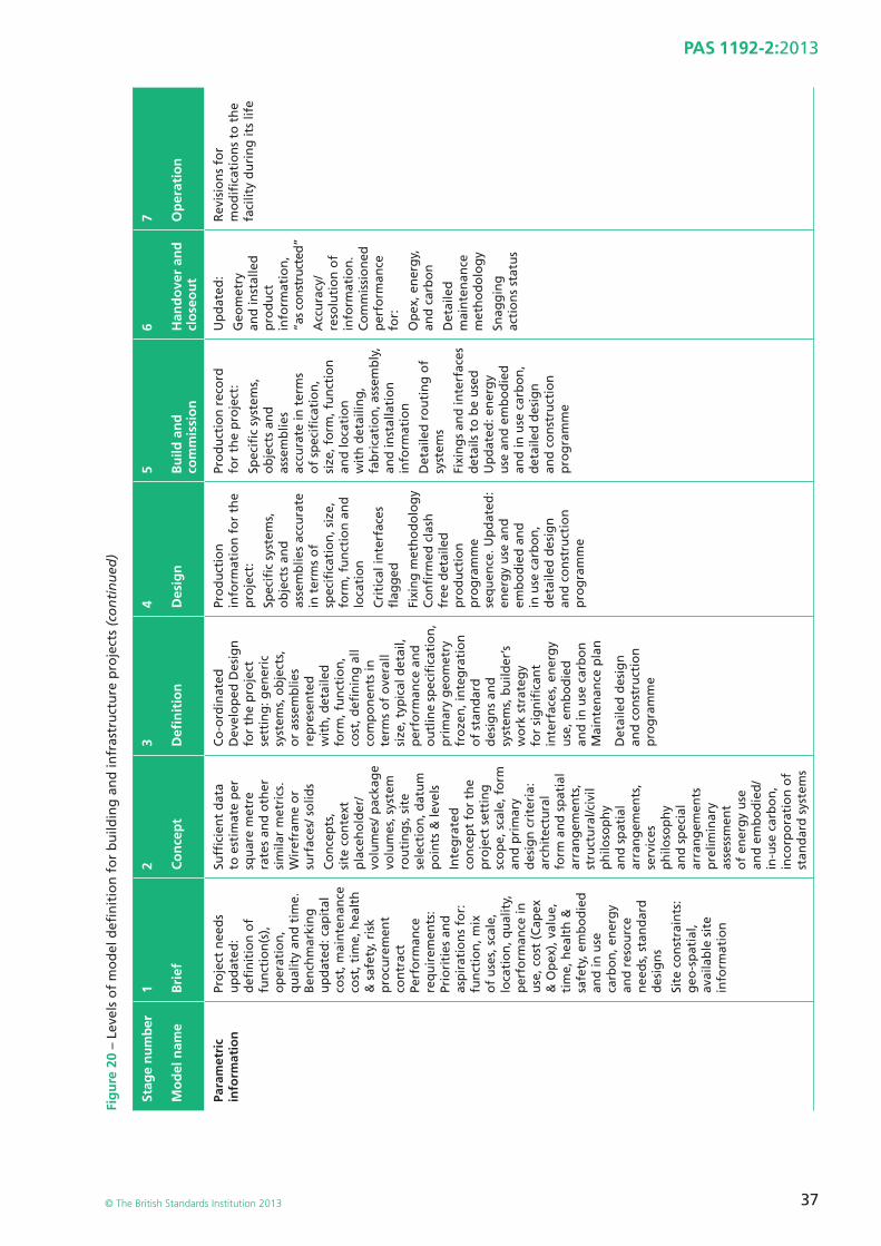
37
PAS 1192-2:2013
© The British Standards Institution 2013
Fig
ure
20
– Le
vels
of
mo
del
defi
nit
ion
fo
r b
uild
ing
an
d in
fras
tru
ctu
re p
roje
cts
(co
nti
nu
ed)
Stag
e n
um
ber
Mo
del
nam
e
1 Bri
ef
2 Co
nce
pt
3 Defi
nit
ion
4 Des
ign
5 Bu
ild a
nd
co
mm
issi
on
6 Han
do
ver
and
cl
ose
ou
t
7 Op
erat
ion
Para
met
ric
info
rmat
ion
Pro
ject
nee
ds
up
dat
ed:
defi
nit
ion
of
fun
ctio
n(s
),
op
erat
ion
, q
ual
ity
and
tim
e.
Ben
chm
arki
ng
u
pd
ated
: cap
ital
co
st, m
ain
ten
ance
co
st, t
ime,
hea
lth
&
saf
ety,
ris
k p
rocu
rem
ent
con
trac
t Pe
rfo
rman
ce
req
uir
emen
ts:
Prio
riti
es a
nd
as
pir
atio
ns
for:
fu
nct
ion
, mix
o
f u
ses,
sca
le,
loca
tio
n, q
ual
ity,
p
erfo
rman
ce in
u
se, c
ost
(C
apex
&
Op
ex),
val
ue,
ti
me,
hea
lth
&
safe
ty, e
mb
od
ied
an
d in
use
ca
rbo
n, e
ner
gy
and
res
ou
rce
nee
ds,
sta
nd
ard
d
esig
ns
Site
co
nst
rain
ts:
geo
-sp
atia
l, av
aila
ble
sit
e in
form
atio
n
Suffi
cie
nt
dat
a to
est
imat
e p
er
squ
are
met
re
rate
s an
d o
ther
si
mila
r m
etri
cs.
Wir
efra
me
or
surf
aces
/ so
lids
Co
nce
pts
, si
te c
on
text
p
lace
ho
lder
/vo
lum
es/ p
acka
ge
volu
mes
, sys
tem
ro
uti
ng
s, s
ite
sele
ctio
n, d
atu
m
po
ints
& le
vels
Inte
gra
ted
co
nce
pt
for
the
pro
ject
set
tin
g
sco
pe,
sca
le, f
orm
an
d p
rim
ary
des
ign
cri
teri
a:
arch
itec
tura
l fo
rm a
nd
sp
atia
l ar
ran
gem
ents
, st
ruct
ura
l/civ
il p
hilo
sop
hy
and
sp
atia
l ar
ran
gem
ents
, se
rvic
es
ph
iloso
ph
y an
d s
pec
ial
arra
ng
emen
ts
pre
limin
ary
asse
ssm
ent
of
ener
gy
use
an
d e
mb
od
ied
/ in
-use
car
bo
n,
inco
rpo
rati
on
of
stan
dar
d s
yste
ms
Co
-ord
inat
ed
Dev
elo
ped
Des
ign
fo
r th
e p
roje
ct
sett
ing
: gen
eric
sy
stem
s, o
bje
cts,
o
r as
sem
blie
s re
pre
sen
ted
w
ith
, det
aile
d
form
, fu
nct
ion
, co
st, d
efi n
ing
all
com
po
nen
ts in
te
rms
of
ove
rall
size
, typ
ical
det
ail,
per
form
ance
an
d
ou
tlin
e sp
ecifi
cat
ion
, p
rim
ary
geo
met
ry
fro
zen
, in
teg
rati
on
o
f st
and
ard
d
esig
ns
and
sy
stem
s, b
uild
er’s
w
ork
str
ateg
y fo
r si
gn
ifi c
ant
inte
rfac
es, e
ner
gy
use
, em
bo
die
d
and
in u
se c
arb
on
M
ain
ten
ance
pla
n
Det
aile
d d
esig
n
and
co
nst
ruct
ion
p
rog
ram
me
Pro
du
ctio
n
info
rmat
ion
fo
r th
e p
roje
ct:
Spec
ifi c
sys
tem
s,
ob
ject
s an
d
asse
mb
lies
accu
rate
in
ter
ms
of
spec
ifi c
atio
n, s
ize,
fo
rm, f
un
ctio
n a
nd
lo
cati
on
Cri
tica
l in
terf
aces
fl
agg
ed
Fixi
ng
met
ho
do
log
y C
on
fi rm
ed c
lash
fr
ee d
etai
led
p
rod
uct
ion
p
rog
ram
me
seq
uen
ce. U
pd
ated
: en
erg
y u
se a
nd
em
bo
die
d a
nd
in
use
car
bo
n,
det
aile
d d
esig
n
and
co
nst
ruct
ion
p
rog
ram
me
Pro
du
ctio
n r
eco
rd
for
the
pro
ject
:
Spec
ifi c
sys
tem
s,
ob
ject
s an
d
asse
mb
lies
accu
rate
in t
erm
s o
f sp
ecifi
cat
ion
, si
ze, f
orm
, fu
nct
ion
an
d lo
cati
on
w
ith
det
ailin
g,
fab
rica
tio
n, a
ssem
bly
, an
d in
stal
lati
on
in
form
atio
n
Det
aile
d r
ou
tin
g o
f sy
stem
s
Fixi
ng
s an
d in
terf
aces
d
etai
ls t
o b
e u
sed
U
pd
ated
: en
erg
y u
se a
nd
em
bo
die
d
and
in u
se c
arb
on
, d
etai
led
des
ign
an
d c
on
stru
ctio
n
pro
gra
mm
e
Up
dat
ed:
Geo
met
ry
and
inst
alle
d
pro
du
ct
info
rmat
ion
, “a
s co
nstr
ucte
d”
Acc
ura
cy/
reso
luti
on
of
info
rmat
ion
. C
om
mis
sio
ned
p
erfo
rman
ce
for:
Op
ex, e
ner
gy,
an
d c
arb
on
Det
aile
d
mai
nte
nan
ce
met
ho
do
log
y
Snag
gin
g
acti
on
s st
atu
s
Rev
isio
ns
for
mo
difi
cat
ion
s to
th
e fa
cilit
y d
uri
ng
its
life
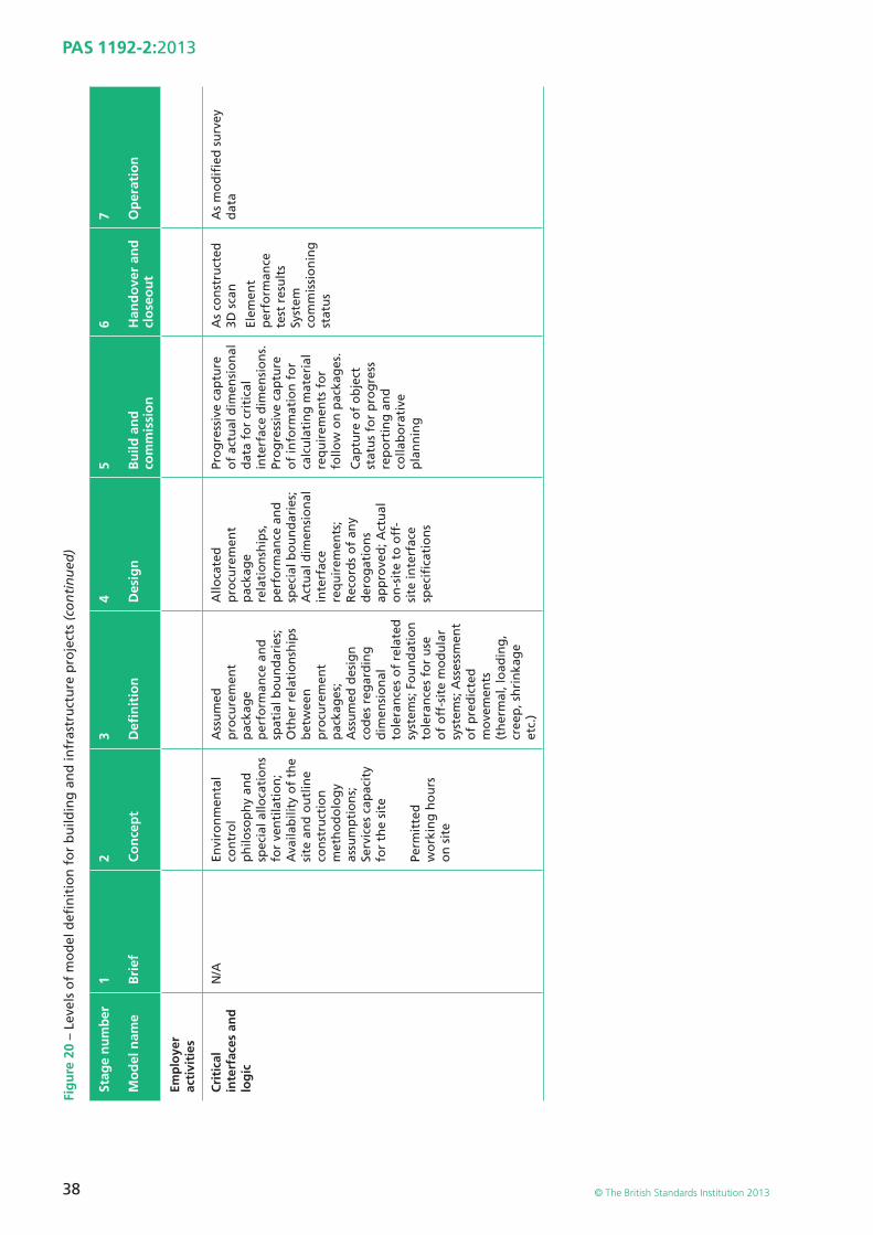
38
PAS 1192-2:2013
© The British Standards Institution 2013
Fig
ure
20
– Le
vels
of
mo
del
defi
nit
ion
fo
r b
uild
ing
an
d in
fras
tru
ctu
re p
roje
cts
(co
nti
nu
ed)
Stag
e n
um
ber
Mo
del
nam
e
1 Bri
ef
2 Co
nce
pt
3 Defi
nit
ion
4 Des
ign
5 Bu
ild a
nd
co
mm
issi
on
6 Han
do
ver
and
cl
ose
ou
t
7 Op
erat
ion
Emp
loye
r ac
tivi
ties
Cri
tica
l in
terf
aces
an
d
log
ic
N/A
Envi
ron
men
tal
con
tro
l p
hilo
sop
hy
and
sp
ecia
l allo
cati
on
s fo
r ve
nti
lati
on
; A
vaila
bili
ty o
f th
e si
te a
nd
ou
tlin
e co
nst
ruct
ion
m
eth
od
olo
gy
assu
mp
tio
ns;
Se
rvic
es c
apac
ity
for
the
site
Perm
itte
d
wo
rkin
g h
ou
rs
on
sit
e
Ass
um
ed
pro
cure
men
t p
acka
ge
per
form
ance
an
d
spat
ial b
ou
nd
arie
s;
Oth
er r
elat
ion
ship
s b
etw
een
p
rocu
rem
ent
pac
kag
es;
Ass
um
ed d
esig
n
cod
es r
egar
din
g
dim
ensi
on
al
tole
ran
ces
of
rela
ted
sy
stem
s; F
ou
nd
atio
n
tole
ran
ces
for
use
o
f o
ff-s
ite
mo
du
lar
syst
ems;
Ass
essm
ent
of
pre
dic
ted
m
ove
men
ts
(th
erm
al, l
oad
ing
, cr
eep
, sh
rin
kag
e et
c.)
Allo
cate
d
pro
cure
men
t p
acka
ge
rela
tio
nsh
ips,
p
erfo
rman
ce a
nd
sp
ecia
l bo
un
dar
ies;
A
ctu
al d
imen
sio
nal
in
terf
ace
req
uir
emen
ts;
Rec
ord
s o
f an
y d
ero
gat
ion
s ap
pro
ved
; Act
ual
o
n-s
ite
to o
ff-
site
inte
rfac
e sp
ecifi
cat
ion
s
Pro
gre
ssiv
e ca
ptu
re
of
actu
al d
imen
sio
nal
d
ata
for
crit
ical
in
terf
ace
dim
ensi
on
s.
Pro
gre
ssiv
e ca
ptu
re
of
info
rmat
ion
fo
r ca
lcu
lati
ng
mat
eria
l re
qu
irem
ents
fo
r fo
llow
on
pac
kag
es.
Cap
ture
of
ob
ject
st
atu
s fo
r p
rog
ress
re
po
rtin
g a
nd
co
llab
ora
tive
p
lan
nin
g
As
con
stru
cted
3D
sca
n
Elem
ent
per
form
ance
te
st r
esu
lts
Syst
em
com
mis
sio
nin
g
stat
us
As
mo
difi
ed
su
rvey
d
ata
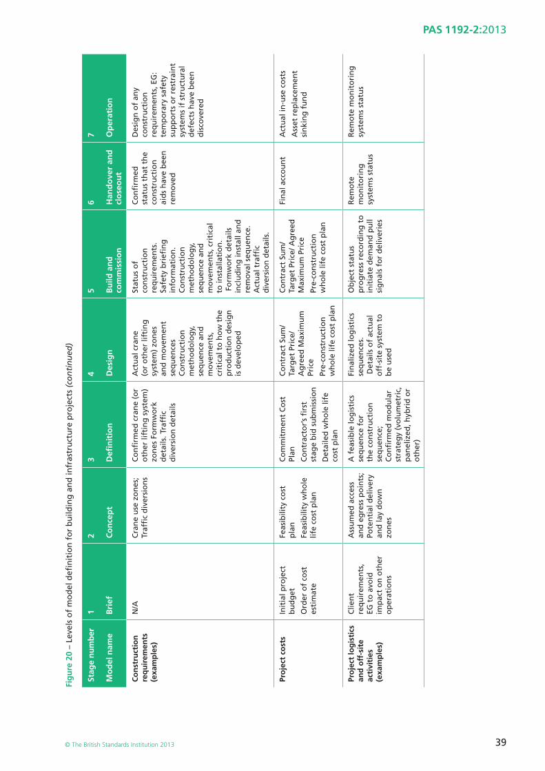
39
PAS 1192-2:2013
© The British Standards Institution 2013
Fig
ure
20
– Le
vels
of
mo
del
defi
nit
ion
fo
r b
uild
ing
an
d in
fras
tru
ctu
re p
roje
cts
(co
nti
nu
ed)
Stag
e n
um
ber
Mo
del
nam
e
1 Bri
ef
2 Co
nce
pt
3 Defi
nit
ion
4 Des
ign
5 Bu
ild a
nd
co
mm
issi
on
6 Han
do
ver
and
cl
ose
ou
t
7 Op
erat
ion
Co
nst
ruct
ion
re
qu
irem
ents
(e
xam
ple
s)
N/A
Cra
ne
use
zo
nes
; Tr
affi
c d
iver
sio
ns
Co
nfi
rmed
cra
ne
(or
oth
er li
ftin
g s
yste
m)
zon
es F
orm
wo
rk
det
ails
. Tra
ffi c
d
iver
sio
n d
etai
ls
Act
ual
cra
ne
(or
oth
er li
ftin
g
syst
em)
zon
es
and
mo
vem
ent
seq
uen
ces
Co
nst
ruct
ion
m
eth
od
olo
gy,
se
qu
ence
an
d
mo
vem
ents
, cr
itic
al t
o h
ow
th
e p
rod
uct
ion
des
ign
is
dev
elo
ped
Stat
us
of
con
stru
ctio
n
req
uir
emen
ts.
Safe
ty b
riefi
ng
in
form
atio
n.
Co
nst
ruct
ion
m
eth
od
olo
gy,
se
qu
ence
an
d
mo
vem
ents
, cri
tica
l to
inst
alla
tio
n.
Fo
rmw
ork
det
ails
in
clu
din
g in
stal
l an
d
rem
ova
l seq
uen
ce.
Act
ual
tra
ffi c
d
iver
sio
n d
etai
ls.
Co
nfi
rmed
st
atu
s th
at t
he
con
stru
ctio
n
aid
s h
ave
bee
n
rem
ove
d
Des
ign
of
any
con
stru
ctio
n
req
uir
emen
ts, E
G:
tem
po
rary
saf
ety
sup
po
rts
or
rest
rain
t sy
stem
s if
str
uct
ura
l d
efec
ts h
ave
bee
n
dis
cove
red
Pro
ject
co
sts
Init
ial p
roje
ct
bu
dg
et
Ord
er o
f co
st
esti
mat
e
Feas
ibili
ty c
ost
p
lan
Feas
ibili
ty w
ho
le
life
cost
pla
n
Co
mm
itm
ent
Co
st
Plan
Co
ntr
acto
r’s
fi rs
t st
age
bid
su
bm
issi
on
Det
aile
d w
ho
le li
fe
cost
pla
n
Co
ntr
act
Sum
/Ta
rget
Pri
ce/
Ag
reed
Max
imu
m
Pric
e
Pre-
con
stru
ctio
n
wh
ole
life
co
st p
lan
Co
ntr
act
Sum
/Ta
rget
Pri
ce/ A
gre
ed
Max
imu
m P
rice
Pre-
con
stru
ctio
n
wh
ole
life
co
st p
lan
Fin
al a
cco
un
tA
ctu
al in
-use
co
sts
Ass
et r
epla
cem
ent
sin
kin
g f
un
d
Pro
ject
log
isti
cs
and
off
-sit
e ac
tivi
ties
(e
xam
ple
s)
Clie
nt
req
uir
emen
ts,
EG t
o a
void
im
pac
t o
n o
ther
o
per
atio
ns
Ass
um
ed a
cces
s an
d e
gre
ss p
oin
ts;
Pote
nti
al d
eliv
ery
and
lay
do
wn
zo
nes
A f
easi
ble
log
isti
cs
seq
uen
ce f
or
the
con
stru
ctio
n
seq
uen
ce;
Co
nfi
rmed
mo
du
lar
stra
teg
y (v
olu
met
ric,
p
anel
ized
, hyb
rid
or
oth
er)
Fin
aliz
ed lo
gis
tics
se
qu
ence
s. D
etai
ls o
f ac
tual
o
ff-s
ite
syst
em t
o
be
use
d
Ob
ject
sta
tus
pro
gre
ss r
eco
rdin
g t
o
init
iate
dem
and
pu
ll si
gn
als
for
del
iver
ies
Rem
ote
m
on
ito
rin
g
syst
ems
stat
us
Rem
ote
mo
nit
ori
ng
sy
stem
s st
atu
s
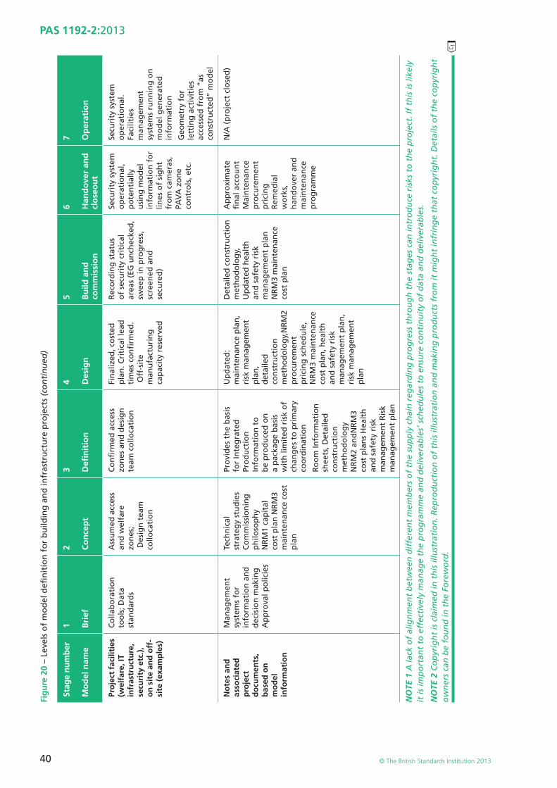
��
40
PAS 1192-2:2013
© The British Standards Institution 2013
Fig
ure
20
– Le
vels
of
mo
del
defi
nit
ion
fo
r b
uild
ing
an
d in
fras
tru
ctu
re p
roje
cts
(co
nti
nu
ed)
Stag
e n
um
ber
Mo
del
nam
e
1 Bri
ef
2 Co
nce
pt
3 Defi
nit
ion
4 Des
ign
5 Bu
ild a
nd
co
mm
issi
on
6 Han
do
ver
and
cl
ose
ou
t
7 Op
erat
ion
Pro
ject
fac
iliti
es
(wel
fare
, IT
infr
astr
uct
ure
, se
curi
ty e
tc.)
, o
n s
ite
and
off
-si
te (
exam
ple
s)
Co
llab
ora
tio
n
too
ls; D
ata
stan
dar
ds
Ass
um
ed a
cces
s an
d w
elfa
re
zon
es;
Des
ign
tea
m
collo
cati
on
Co
nfi
rmed
acc
ess
zon
es a
nd
des
ign
te
am c
ollo
cati
on
Fin
aliz
ed, c
ost
ed
pla
n. C
riti
cal l
ead
ti
mes
co
nfi
rmed
. O
ff-s
ite
man
ufa
ctu
rin
g
cap
acit
y re
serv
ed
Rec
ord
ing
sta
tus
of
secu
rity
cri
tica
l ar
eas
(EG
un
chec
ked
, sw
eep
in p
rog
ress
, sc
reen
ed a
nd
se
cure
d)
Secu
rity
sys
tem
o
per
atio
nal
, p
ote
nti
ally
u
sin
g m
od
el
info
rmat
ion
fo
r lin
es o
f si
gh
t fr
om
cam
eras
, PA
VA
zo
ne
con
tro
ls, e
tc.
Secu
rity
sys
tem
o
per
atio
nal
.Fa
cilit
ies
man
agem
ent
syst
ems
run
nin
g o
n
mo
del
gen
erat
ed
info
rmat
ion
Geo
met
ry f
or
lett
ing
act
ivit
ies
acce
ssed
fro
m “
as
con
stru
cted
” m
od
el
No
tes
and
as
soci
ated
p
roje
ct
do
cum
ents
, b
ased
on
m
od
el
info
rmat
ion
Man
agem
ent
syst
ems
for
info
rmat
ion
an
d
dec
isio
n m
akin
gA
pp
rova
l po
licie
s
Tech
nic
al
stra
teg
y st
ud
ies
Co
mm
issi
on
ing
p
hilo
sop
hy
NR
M1
cap
ital
co
st p
lan
NR
M3
mai
nte
nan
ce c
ost
p
lan
Pro
vid
es t
he
bas
is
for
Inte
gra
ted
Pr
od
uct
ion
In
form
atio
n t
o
be
pro
du
ced
on
a
pac
kag
e b
asis
w
ith
lim
ited
ris
k o
f ch
ang
es t
o p
rim
ary
coo
rdin
atio
n
Ro
om
Info
rmat
ion
sh
eets
, Det
aile
d
con
stru
ctio
n
met
ho
do
log
yN
RM
2 an
dN
RM
3 co
st p
lan
s H
ealt
h
and
saf
ety
risk
m
anag
emen
t R
isk
man
agem
ent
pla
n
Up
dat
ed:
mai
nte
nan
ce p
lan
, ri
sk m
anag
emen
t p
lan
, d
etai
led
co
nst
ruct
ion
m
eth
od
olo
gy,
NR
M2
pro
cure
men
t p
rici
ng
sch
edu
le,
NR
M3
mai
nte
nan
ce
cost
pla
n, h
ealt
h
and
saf
ety
risk
m
anag
emen
t p
lan
,ri
sk m
anag
emen
t p
lan
Det
aile
d c
on
stru
ctio
n
met
ho
do
log
y,
Up
dat
ed h
ealt
h
and
saf
ety
risk
m
anag
emen
t p
lan
N
RM
3 m
ain
ten
ance
co
st p
lan
Ap
pro
xim
ate
fi n
al a
cco
un
t M
ain
ten
ance
p
rocu
rem
ent
pri
cin
g
Rem
edia
l w
ork
s,
han
do
ver
and
m
ain
ten
ance
p
rog
ram
me
N/A
(p
roje
ct c
lose
d)
NO
TE 1
A la
ck o
f al
ign
men
t b
etw
een
dif
fere
nt
mem
ber
s o
f th
e su
pp
ly c
hai
n r
egar
din
g p
rog
ress
th
rou
gh
th
e st
ages
can
intr
od
uce
ris
ks t
o t
he
pro
ject
. If
this
is li
kely
it
is im
po
rtan
t to
eff
ecti
vely
man
age
the
pro
gra
mm
e an
d d
eliv
erab
les’
sch
edu
les
to e
nsu
re c
on
tin
uit
y o
f d
ata
and
del
iver
able
s.
NO
TE 2
Co
pyr
igh
t is
cla
imed
in t
his
illu
stra
tio
n. R
epro
du
ctio
n o
f th
is il
lust
rati
on
an
d m
akin
g p
rod
uct
s fr
om
it m
igh
t in
frin
ge
that
co
pyr
igh
t. D
etai
ls o
f th
e co
pyr
igh
t o
wn
ers
can
be
fou
nd
in t
he
Fore
wo
rd.
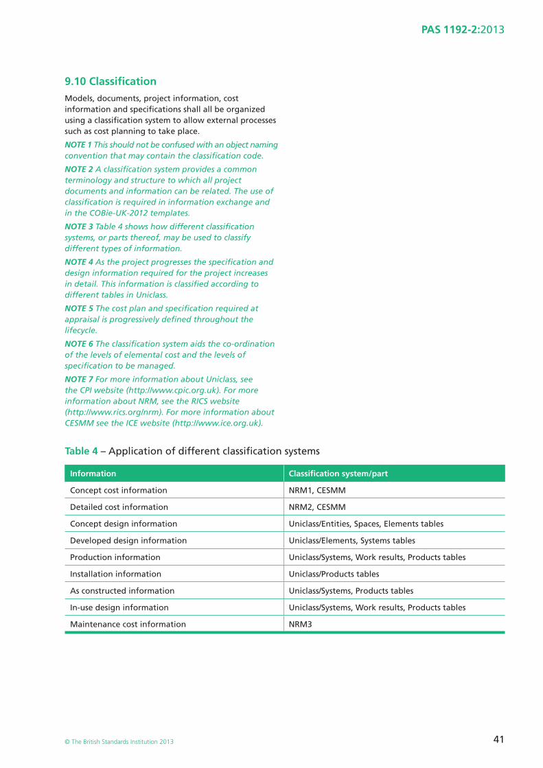
41
PAS 1192-2:2013
© The British Standards Institution 2013
9.10 Classifi cationModels, documents, project information, cost information and specifi cations shall all be organized using a classifi cation system to allow external processes such as cost planning to take place.
NOTE 1 This should not be confused with an object naming convention that may contain the classifi cation code.
NOTE 2 A classifi cation system provides a common terminology and structure to which all project documents and information can be related. The use of classifi cation is required in information exchange and in the COBie-UK-2012 templates.
NOTE 3 Table 4 shows how different classifi cation systems, or parts thereof, may be used to classify different types of information.
NOTE 4 As the project progresses the specifi cation and design information required for the project increases in detail. This information is classifi ed according to different tables in Uniclass.
NOTE 5 The cost plan and specifi cation required at appraisal is progressively defi ned throughout the lifecycle.
NOTE 6 The classifi cation system aids the co-ordination of the levels of elemental cost and the levels of specifi cation to be managed.
NOTE 7 For more information about Uniclass, see the CPI website (http://www.cpic.org.uk). For more information about NRM, see the RICS website (http://www.rics.org/nrm). For more information about CESMM see the ICE website (http://www.ice.org.uk).
Table 4 – Application of different classifi cation systems
Information Classifi cation system/part
Concept cost information NRM1, CESMM
Detailed cost information NRM2, CESMM
Concept design information Uniclass/Entities, Spaces, Elements tables
Developed design information Uniclass/Elements, Systems tables
Production information Uniclass/Systems, Work results, Products tables
Installation information Uniclass/Products tables
As constructed information Uniclass/Systems, Products tables
In-use design information Uniclass/Systems, Work results, Products tables
Maintenance cost information NRM3
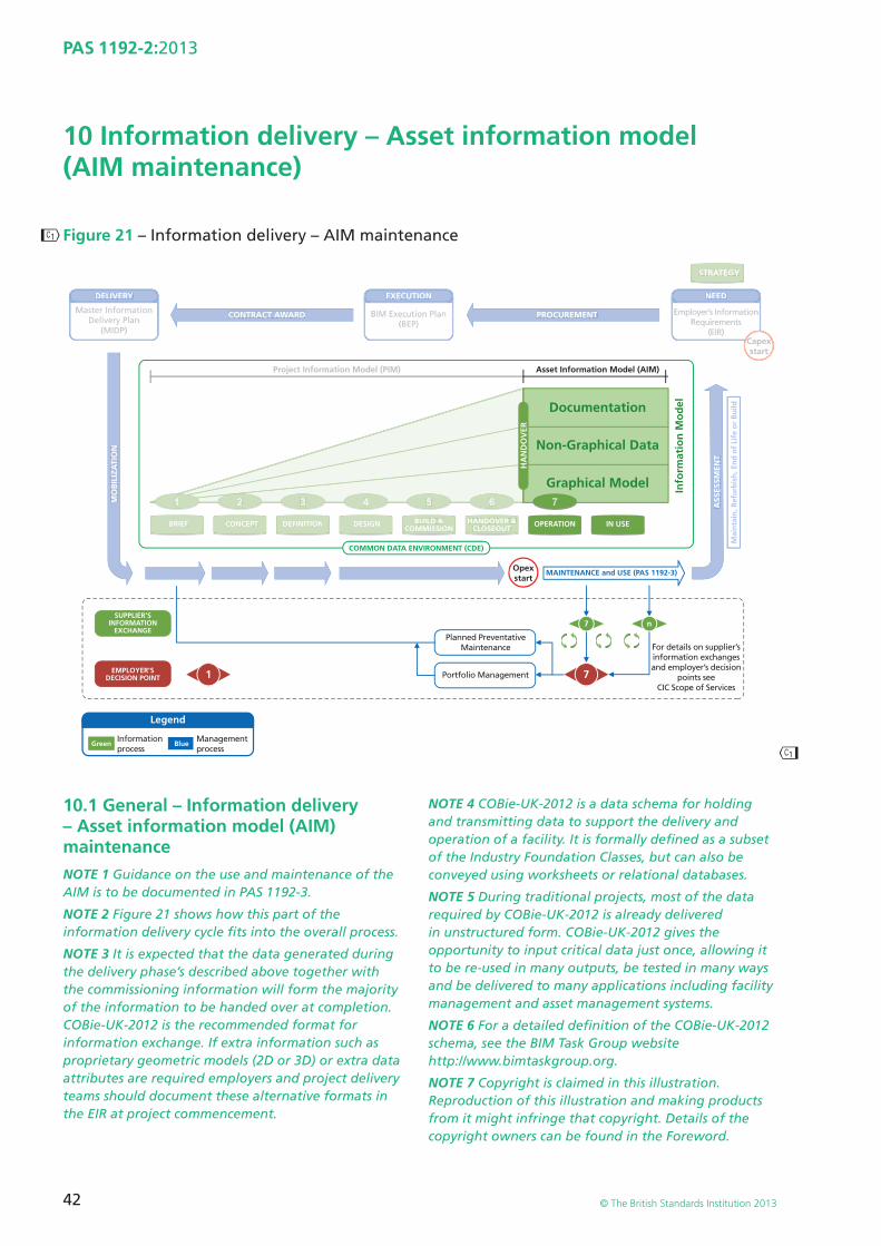
��
��
42
PAS 1192-2:2013
© The British Standards Institution 2013
10 Information delivery – Asset information model (AIM maintenance)
Figure 21 – Information delivery – AIM maintenance
NEED
Employer’s InformationRequirements
(EIR)
1
2 3 4 5 61
7
7 n
DELIVERY
CONTRACT AWARD
Legend
PROCUREMENT
ASS
ESSM
ENT
MO
BIL
IZA
TIO
N
Mai
nta
in, R
efu
rbis
h, E
nd
of
Life
or
Bu
ild
MAINTENANCE and USE (PAS 1192-3)
STRATEGY
Opexstart
Capexstart
Master InformationDelivery Plan
(MIDP)
SUPPLIER’SINFORMATION
EXCHANGE
EMPLOYER’SDECISION POINT
Green Blue
EXECUTION
BIM Execution Plan(BEP)
For details on supplier’sinformation exchangesand employer’s decision
points seeCIC Scope of Services
Informationprocess
Managementprocess
Project Information Model (PIM)
HANDOVER &CLOSEOUT
BUILD &COMMISSION
DESIGNBRIEF CONCEPT DEFINITION
NEED
Employer’s InformationRequirements
(EIR)
2 3 4 5 61
DELIVERY
CONTRACT AWARD PROCUREMENT
ASS
ESSM
ENT
MO
BIL
IZA
TIO
N
Mai
nta
in, R
efu
rbis
h, E
nd
of
Life
or
Bu
ild
STRATEGY
CapexCstart
Master InformationDelivery Plan
(MIDP)
EXECUTION
BIM Execution Plan(BEP)
Project Information Model (PIM)
HANDOVER &CLOSEOUT
BUILD &COMMISSION
DESIGNBRIEF CONCEPT DEFINITION
Portfolio Management
Planned PreventativeMaintenance
7
OPERATION IN USE
Non-Graphical Data
Documentation
HA
ND
OV
ER
Graphical Model
Asset Information Model (AIM)
Info
rmat
ion
Mo
del
COMMON DATA ENVIRONMENT (CDE)
10.1 General – Information delivery – Asset information model (AIM) maintenanceNOTE 1 Guidance on the use and maintenance of the AIM is to be documented in PAS 1192-3.
NOTE 2 Figure 21 shows how this part of the information delivery cycle fi ts into the overall process.
NOTE 3 It is expected that the data generated during the delivery phase’s described above together with the commissioning information will form the majority of the information to be handed over at completion. COBie-UK-2012 is the recommended format for information exchange. If extra information such as proprietary geometric models (2D or 3D) or extra data attributes are required employers and project delivery teams should document these alternative formats in the EIR at project commencement.
NOTE 4 COBie-UK-2012 is a data schema for holding and transmitting data to support the delivery and operation of a facility. It is formally defi ned as a subset of the Industry Foundation Classes, but can also be conveyed using worksheets or relational databases.
NOTE 5 During traditional projects, most of the data required by COBie-UK-2012 is already delivered in unstructured form. COBie-UK-2012 gives the opportunity to input critical data just once, allowing it to be re-used in many outputs, be tested in many ways and be delivered to many applications including facility management and asset management systems.
NOTE 6 For a detailed defi nition of the COBie-UK-2012 schema, see the BIM Task Group website http://www.bimtaskgroup.org.
NOTE 7 Copyright is claimed in this illustration. Reproduction of this illustration and making products from it might infringe that copyright. Details of the copyright owners can be found in the Foreword.
43
PAS 1192-2:2013
© The British Standards Institution 2013
10.2 Handover process between CAPEX and OPEX10.2.1 The effective transfer of structured information between the asset lifecycle stages delivers signifi cant value. To effectively enable this, formal handover processes shall be documented in the EIR. The document shall defi ne the structure, process and content of information to be exchanged. This document shall form the basis for the operational contract documentation.
In addition, appropriate surveys such as point cloud or LiDAR shall be provided to verify the completeness of the as-constructed model.
NOTE 1 A number of formal processes exist such as Soft Landings (see http://www.bsria.co.uk/services/design/soft-landings) or in the case of the public sector “Government Soft Landings” (GSL) (see http://www.bimtaskgroup.org/gsl).
NOTE 2 The handover process and detailed operational processes are documented in PAS 55; the data requirements for these and associated activities are to be documented in PAS 1192-3.
NOTE 3 Evaluation of the operational performance of the asset is to be documented in PAS 1192-3.
44
PAS 1192-2:2013
© The British Standards Institution 2013
Annex A (informative) Terms, defi nitions and abbreviations for BIM documentation
A.1 2DTwo-dimensional.
A.2 2D drawingA 2D drawing contains a view of a model that is referenced into a “drawing sheet template” (blank drawing and title block). Such drawings must always be considered to be static documents, as they are drawing renditions or snapshots of the design’s model fi les. Such renditions are generated each time the drawing is prepared for “sharing” at regular milestones.
A.3 2D modelA model with entities having two-dimensional properties. Such models are always to be considered to be dynamic, as they will be made up of “model fi les” that are “x-ref” or “reference” fi les.
A.4 3DThree-dimensional.
A.5 3D modelA model with objects having three-dimensional properties. Such models are always to be considered to be dynamic, as they will be made up of “model fi les” that are “x-ref” or “reference” fi les.
A.6 3D visualization3D images from the 3D CAD model, or a virtual representation of the building or facility to be constructed; used for visualizing the project.
A.7 archiveComponent of the common data environment (CDE).
NOTE The archive section of the CDE is for inactive or superseded information. Such information will provide a history of the project information transfers, sharing, change orders and knowledge retention, and can be used for other contractual purposes or “discovery”.
A.8 as-built or as-constructedA model consisting of documentation, non- graphical information and graphical information defi ning the delivered project.
“As-built” is defi ned as the record drawings and documentation defi ning deviation to the designed information occurring during construction at the end of the project.
“As-constructed” defi nes the defect and deviation to the designed model occurring during construction. The “as-constructed” model and its appended documentation are continually updated through re-measurement as construction progresses. This allows for deviation to be reviewed with respect to the following packages and making knowledgeable assessment of impact and resolution.
A.9 assemblyGroup of components or types to enable the reuse of standardized design or specifi cation elements improving productivity of design and delivery as well as providing a location to hold specifi cations and lessons learnt in a simple and useable way. They may hold benchmark data for cost and carbon impacts.
The contents of assemblies may themselves have attributes and classifi cations. These properties may include key data which is attached (to the object) for use once it is placed into a model and may include cost, CO2, programme, maintenance and other key information.
A.10 attributePiece of data forming a partial description of an object or entity.
A.11 authorOriginator of model fi les, drawings or documents.
45
PAS 1192-2:2013
© The British Standards Institution 2013
A.12 AIM/Asset Information ModelMaintained information model used to manage, maintain and operate the asset.
A.13 BEP/BIM Execution PlanPlan prepared by the suppliers to explain how the information modelling aspects of a project will be carried out.
A.14 BIMBuilding information modelling.
A.15 BIM(M) Sometimes Building Information Management but as BIM(M) Building Information and Management.
A.16 BIM Viewer Software used to view 3D rendition without requiring the user to have the software that produced the model (Navisworks, Navigator, Solibris, etc.; also eDrawing to view both 2D and 3D rendition).
A.17 CADComputer aided design.
A.18 CAD standardStandard used to produce CAD models that will include origins, units, layering conventions, line specifi cations, fi le-naming conventions, drawing numbering, etc.
A.19 CAD viewerSoftware used to view rendition print fi les without requiring the user to have the software that produced the model. (Adobe PDF, DWF, etc.)
A.20 CADDComputer aided design and draughting.
NOTE A computer-aided design software application with additional features such as the ability to output drawings from the software.
A.21 CAWSCommon Arrangement of Work Sections, published by CPIC for use in specifi cations and bills of quantities.
A.22 CDMConstruction (Design and Management) regulations.
A.23 CIATChartered Institute of Architectural Technologists.
A.24 CIBSEChartered Institution of Building Services Engineers.
A.25 CIC Scope of ServicesMulti-disciplinary scope of services published by the Construction Industry Council (CIC) for use by members of the project team on major projects.
A.26 CI/SfBThe UK version of the Construction Indexing Classifi cation System for Construction products and elements – a version of the SfB classifi cation system originating from Sweden.
A.27 clash rendition (CR)Rendition of the native format model fi le to be used specifi cally for spatial coordination processes. To achieve clash avoidance or to be used for clash detection.
A.28 classifi cationSystematic arrangement of headings and sub-headings for aspects of construction work including the nature of assets, construction elements, systems and products.
A.29 clientIndividual or organization commissioning a built asset.
NOTE The client may be different from the employer.
46
PAS 1192-2:2013
© The British Standards Institution 2013
A.30 common data environment (CDE)Single source of information for any given project, used to collect, manage and disseminate all relevant approved project documents for multi-disciplinary teams in a managed process.
NOTE 1 A CDE may use a project server, an extranet, a fi le-based retrieval system or other suitable toolset.
NOTE 2 Note CDE as defi ned in the BS 1192:2007.
NOTE 3 The fundamental requirement for producing information through a collaborative activity is to share information early, and to trust the information that is being shared as well as the originator of that information. What is needed is a disciplined auditable process that is transparent and controllable.
The method for managing a project through a common data environment (CDE) is applicable to all sizes of practice, and in particular it prepares that offi ce to be able to work collaboratively. As a standard that is adopted by all, it will help to remove the problem of having to constantly retrain on each and every project when client standards are to be applied. If the clients accept the procedures and make them contractual, then these problems disappear.
The CDE is a means of allowing information to be shared effi ciently and accurately between all members of the project team – whether that information is in 2D or 3D, or indeed textual or numeric. The CDE enables multi-disciplinary design teams to collaborate in a managed environment, where the build-up and development of information follows the design, manufacturing and construction sequence. See BS 1192:2007 or Building Information Modelling – A Standard Framework and Guide to BS 1192, Richards, 2010.
The CDE process also ensures that information is only generated once and is then reused as necessary by all members of the supply chain. It also ensures that the information is constantly updated and enriched for fi nal delivery as part of the Facilities Management (FM) document.
A.31 componentSynonym for “occurrence”.
A.32 concessionPermission to use or release a product that does not conform to specifi c requirements
[BS ISO 10007:2003]
or a concession against a contractrequirement (gain permission for non-conformance).
A.33 concurrent engineeringSystematic approach to the integrated, concurrent design of products and their related processes, including manufacture and support (based on IDA defi nition). In a construction context it incorporates both early contractor and owner/operator involvement.
A.34 confi gurationInterrelated functional and physical characteristics of a product defi ned in product confi guration information.
[BS ISO 10007:2003]
A.35 confi guration itemEntity within a confi guration that satisfi es an end use function.
[BS ISO 10007:2003]
A.36 confi guration managementCo-ordinated activities to direct and control confi guration.
[BS ISO 10007:2003]
A.37 confi guration status accountingFormalized recording and reporting of product confi guration information, the status of proposed changes and the status of the implementation of approved changes.
[BS ISO 10007:2003]
A.38 CPIConstruction project information.
A.39 CPIcConstruction Project Information Committee.
A.40 CPIxConstruction Project Information Xchange.
47
PAS 1192-2:2013
© The British Standards Institution 2013
A.41 CSGConstructive solid geometry representation. A CSG object is composed from standard primitives using regularised Boolean operations and rigid motions.
A.42 COBie-UK-2012Structured facility information for the commissioning, operation and maintenance of a project often in a neutral spreadsheet format that will be used to supply data to the employer or operator to populate decision-making tools, FM and asset management systems.
NOTE Templates for the preparation of COBie information exchange fi les can be downloaded from the BIM Task Group website: http://www.bimtaskgroup.org.
A.43 dataInformation stored but not yet interpreted or analyzed.
A.44 design intent modelInitial version of the Project Information Model developed by the design suppliers.
A.45 DGNFile extension for Bentley Systems’ MicroStation and Intergraph’s Interactive Graphics Design System CAD programs.
A.46 dispositioning authorityPerson or a group of persons assigned responsibility and authority to make decisions on the confi guration.
[BS ISO 10007:2003]
A.47 DMSDocument management system.
A.48 documentInformation for use in the briefi ng, design, construction, operation, maintenance or decommissioning of a construction project, including but not limited to correspondence, drawings, schedules, specifi cations, calculations, spreadsheets.
NOTE Documents must either be immutable or incorporate a means of controlling changes.
A.49 document repositoryEntity including an electronic data management (EDM) system, project extranet or folder hierarchy on a Windows fi le server.
A.50 drawingStatic, printed, graphical representation of part or all of a project or asset.
A.51 drawing title blockFramework – often containing the project team’s logos – to show the drawing title, number, purpose of issue, status and revision information.
A.52 DWF Design web format. An open, secure fi le format developed by Autodesk for the distribution and communication of design data to view, review, or print design fi les.
A.53 DWGProprietary AutoCAD fi le format.
NOTE DWG (drawing) is a binary fi le format used for storing two and three dimensional design data and metadata. It is the native format for several CAD packages including AutoCAD and is supported by many other CAD applications.
A.54 DXFFile format used mainly for importing and exporting CAD data between AutoCAD and other CAD-related programs.
A.55 earned value analysis (EVA) A method of project performance measurement that integrates cost, time and scope.
48
PAS 1192-2:2013
© The British Standards Institution 2013
A.56 electronic document management system (EDMS)System for storing, retrieving, sharing and otherwise managing electronic documents.
NOTE An EDMS provides more control and better management of computer-generated fi les. It adds enhanced fi le security, revision control, fi le descriptions, extended fi le names and user access privileges to the basic fi le directory management features of the computer operating system.
A.57 employerIndividual or organization for whom the contract is executed and delivered.
A.58 employer’s Information Requirements (EIR)Document setting out the information to be delivered by the supplier as part of the project delivery process to the employer.
A.59 entitySynonym for “object”.
A.60 FMFacilities management.
A.61 gate/stageDivision of a standardized process map for the acquisition of a facility, at some of which the requirements can be delivered.
NOTE The stages at which information exchanges are required should be specifi ed in the EIR by reference to the agreed stage and gate names. See the CIC Scope of Services.
A.62 graphical dataData conveyed using shape and arrangement in space.
A.63 graphic fi leFile format designed specifi cally for representing graphical images.
A.64 IAIInternational Alliance for Interoperability. Now known as Building Smart.
A.65 iBIMIntegrated Building Information Model.
A.66 ICEInstitution of Civil Engineers.
A.67 ICTInformation and communications technology.
A.68 IFC2xIndustry Foundation Class version 2x.
A.69 informationRepresentation of data in a formal manner suitable for communication, interpretation or processing by human beings or computer applications.
A.70 information exchangeStructured collection of information at one of a number of pre-defi ned stages of a project with defi ned format and fi delity.
A.71 Information managementTasks and procedures applied to inputting, processing and generation activities to ensure accuracy and integrity of information.
A.72 information modelThe information model comprises three constituent parts: documentation, non-graphical information and graphical information.
NOTE The model is conveyed using PDF, COBie and native model fi les.
49
PAS 1192-2:2013
© The British Standards Institution 2013
A.73 information modellingUse of data to provide information through better understanding, by applying logic or mathematical functions to derive new data.
A.74 layerAttribute given to entities within CAD fi les enabling their visibility to be controlled. Further values may be assigned to the attribute to enable control whether it can be edited or deleted.
A.75 leanProduction focused on delivering value for the employer and eliminating all non-value-adding activities using an effi cient workfl ow.
A.76 lean principlesUnderstanding value from a client’s perspective, identifying the value stream, establish a balanced fl ow of work, in which the demand for product is pulled from the next customer, with a constant drive for continuous improvement and perfection (Based on “Lean Thinking”, Womack & Jones, 2003 edition).
A.77 levels of model detail (LOD)Description of graphical content of models at each of the stages defi ned for example in the CIC Scope of Services.
A.78 levels of model information (LOI)Description of non-graphical content of models at each of the stages defi ned for example in the CIC Scope of Services.
A.79 master information document index (MIDI)Index specifying a detailed list of the deliverables for a project; for model, sub models, documents and data also allocating responsibility to deliver and the programme for delivery of a project supply chain.
A.80 manageable assetsThose aspects of the facility that may be managed during the facility life-cycle include both physical and spatial objects, and their functional groupings.
NOTE 1 An asset is a uniquely identifi able element which has a fi nancial value and against which maintenance actions are recorded.
NOTE 2 Some aspects, such as the structural frame, or individual pipe and duct segments, fi xings and secondary elements may be excluded from scope by the employer.
A.81 marked-up drawingPaper or electronic drawing that has been marked up with comments from other disciplines or the client.
A.82 master information delivery plan (MIDP)Primary plan for when project information is to be prepared, by whom and using what protocols and procedures, incorporating all relevant TIDPs.
A.83 metricsThe acceptability of the deliverable may be assessed against the requirements shown in the examples and/or against indicative ratios and counts based on the information provided.
A.84 model fi leNative, proprietary format, CAD fi le that can be a 2D or 3D model.
A.85 non-graphical dataData conveyed using alphanumeric characters.
A.86 NRMRICS New Rules of Measurement (NRM) for Building Works: a suite of documents issued by the RICS Quantity Surveying and Construction Professional Group.
A.87 NRM1Order of Cost Estimating and Cost Planning for Capital Building Works.
50
PAS 1192-2:2013
© The British Standards Institution 2013
A.88 NRM2Detailed measurement for building works, provides detailed rules for the measurement and description of building works for the purpose of obtaining tender prices.
A.89 NRM3Order of cost estimating and cost planning for building maintenance works is currently in development and is expected to launch in 2013.
A.90 objectItem having state, behaviour and unique identity – for example, a wall object.
NOTE Wiki: object as anything that we can think or talk about. In a general sense it is any entity.
A.91 originAs the setting out point for a project or programme using co-ordinate geometry or related to the OS or geospatial reference.
A.92 originatorAuthor of models, drawings and documents.
A.93 OSOrdnance Survey.
A.94 PDFPortable Document Format. A standard document format from Adobe Systems for transfer between different computer systems.
A.95 placeholderSimplifi ed or generic representation of a 3D object.
A.96 project delivery teamGroup of organizations or individuals contracted either directly or indirectly to deliver services or products to the project.
A.97 project information model (PIM)Information model developed during the design and production and construction phase of a project, consisting of documentation, non- graphical information and graphical information defi ning the delivered project.
NOTE The PIM is developed fi rstly as a design intent model, showing the architectural and engineering intentions of the design suppliers. Then the PIM is developed into a virtual construction model containing all the objects to be manufactured, installed or constructed. It becomes the basis of the Asset Information Model once handed over.
A.98 project implementation plan (PIP)Statement relating to the suppliers’ IT and human resources capability to deliver the EIR.
NOTE Also contains standard method and procedure.
A.99 published/documentationComponent of the CDE for drawing renditions that have been approved as suitable for a specifi c purpose – for example, suitable for construction.
NOTE The published documentation section of the CDE contains drawings – and, if agreed by the project teams, the native model fi les and renditioned– which are snapshots of the shared information taken at a specifi c time. They are compiled by referencing the relevant approved model fi les into a coordinated model fi le and cutting the views and sections from the models.
A.100 purpose of issueStates the purpose for issuing the document.
A.101 purposesThose aspects of the Facility that are intended to be managed by the facility owner.
NOTE Some purposes, such as supporting the business case, may be common with the briefi ng and design processes.
A.102 RACI indicatorAbbreviation used to identify which of a group of participants or stakeholders are responsible for (“R”), authorize (“A”), contribute to (“C”) or are to be kept informed about (“I”) a project activity
51
PAS 1192-2:2013
© The British Standards Institution 2013
A.103 reference fi leCAD model fi le associated or linked with another CAD model fi le. Also referred to as an “X-ref”.
A.104 renditionDocumentation in a form enabling the information to be viewed, printed and marked up. For example, PDF and DWF fi les are documentation consisting of snapshots of
A.105 requirementsRequirements are the documented expectations of facility owners/commissioners for sharable structured information. These are also referred to as the Employers Information Requirements (EIR) (alternatively, the Clients Information Requirements).
NOTE Detailed requirements are scheduled in the examples.
A.106 revisionUsed to identify revisions of documents, drawing and model fi les.
A.107 RIBARoyal Institute of British Architects.
A.108 RICSRoyal Institution of Chartered Surveyors.
A.109 sharedComponent of the CDE. The shared section of the CDE is where information can be made available to others in a “safe” environment. The early release of information assists in the rapid development of the design solution. To allow this to be achieved, the concept of information “status/suitability” has been adopted.
A.110 SI systemLe Système International d’Unités. International system of units.
A.111 SMPStandard Method and Procedure. Set of standard methods and procedures covering the way information is named, expressed and referenced.
A.112 soft landingsGraduated handover of a built asset from the design and construction team to the operation and maintenance team to allow structured familiarisation of systems and components and fi ne tuning of controls and other building management systems.
A.113 standard fontAgreed set of font types and sizes to be used for the project.
A.114 standard layering conventionSingle layering convention used by the project team.
[BS 1192:2007]
A.115 statusDefi nes the “suitability” of information in a model, drawing or document. Not to be confused with the status in architectural documentation as “new build’, “retain” or “demolish”.
A.116 supplierProvider of services or goods either directly to the employer or to another supplier in a supply chain.
A.117 supplier information modelling assessment formThe form conveying the capability and experience of a supplier to carry out information modelling in a collaborative environment.
A.118 supplier information technology assessment formThe form conveying the capability and IT resources of a supplier for exchanging information in a collaborative environment.
52
PAS 1192-2:2013
© The British Standards Institution 2013
A.119 supply chain capability assessment formForm summarizing the human resource and IT capability of each organization in a supply chain.
A.120 systemGroup of components that work together to provide a specifi c building service such as envelope, ventilation or fi re protection.
A.121 system (IFC)Organized combination of related parts, composed for a common purpose or function or to provide a service. System is essentially a functionally related aggregation of products.
A.122 systems engineeringInterdisciplinary approach enabling the realization of successful systems.
[SOURCE: International Council on Systems Engineering]
A.123 task information delivery plan (TIDP)Federated lists of information deliverables by each task, including format, date and responsibilities.
A.124 TBMTunnel boring machine.
A.125 third party capability assessment formform conveying the information management and IT capabilities of non-design, non-construction organizations in a supply chain.
A.126 UniclassUnifi ed classifi cations for the construction industry sponsored by CC, RICS, RIBA and CIBSE. The classifi cation system is based on CI/SfB, CAWS and other relevant documents. Complying with BS ISO 12006-2.
A.127 userIndividual occupying or using a built asset for its designed purpose.
A.128 virtual construction modelSubsequent version of the Project Information Model developed from the design intent model by the construction supplier and their supply chain.
A.129 volume Manageable spatial subdivision of a project, defi ned by the “project team” as a subdivision of the overall project that allows more than one person to work on the project models simultaneously and consistent with the analysis and design process.
NOTE 1 Analogous to the volume strategy defi ned by the lead designer to allocate volumes within the project to different disciplines into which they carry out their system models (walls, structure, pipework, ductwork, electrical, etc).
Also achieves spatial co-ordination prior to detail design.
Each volume or subdivision is a reference fi le. When one or more referenced fi les is viewed, the full or partial project may be represented.
This subdivision also becomes important when using extranets, as it allows the fi les to be kept to a manageable fi le size.
NOTE 2 This term is defi ned as “zone” in BS 1192:2007.
A.130 versionSub-indexing to revision as used in the common data environment to show the development of information and information models, e.g. if a version is named P1.1, P1 is the revision number and .1 is the version to that revision.
A.131 VPNVirtual private network.
A.132 work in progress (WIP)Component of the CDE.
A.133 x-refCAD model fi le associated or linked with another CAD model fi le. Also referred to as a “reference fi le”.
53
PAS 1192-2:2013
© The British Standards Institution 2013
Bibliography
Standards publicationsFor dated references, only the edition cited applied. For undated references, the latest edition of the referenced document (including any amendments) applies.
BS 7000-4:1996, Design management systems – Part 4: Guide to managing design in construction (currently under review)
BS 8541-1:2011, Library objects for architecture, engineering and construction – Part 1: Identifi cation and classifi cation – Code of practice
BS 8541-2:2011, Library objects for architecture, engineering and construction – Part 2: Recommended 2D symbols of building elements for use in building information modelling
BS 8541-3:2012, Library objects for architecture, engineering and construction – Part 3: Shape and measurement – Code of practice
BS 8541-4:2012, Library objects for architecture, engineering and construction – Part 4: Attributes for specifi cation and assessment – Code of practice
BS 11000-1:2010, Collaborative business relationships – Part 1: A framework specifi cation
BS 11000-2:2010, Collaborative business relationships – Part 2: Guide to implementing BS 11000-1
PAS 55:2008 (all parts), Asset management – Specifi cation for the optimized management of physical assets
PAS 91:2010, Construction related procurement – Prequalifi cation questionnaires
Other publicationsBuilding Information Modelling (BIM) Working Group Strategy Paper (March 2011)
Construction Industry Council (CIC) Scope of Services (revised consultation draft) (2012)
CPIx Protocol. Construction Project Information Committee (CPIC), 2012
CHURCHER, D. Design Framework for Building Services. Third Edition. Bracknell, UK: BSRIA, 2012
Government Construction Strategy (May 2011)
WebsitesBuilding Information Modelling (BIM) Task Group http://www.bimtaskgroup.org
COBie-UK-2012, Reference documentationhttp://www.bimtaskgroup.org/COBie-UK-2012
Construction Industry Council (CIC) http://www.cic.org.uk
Construction Project Information Committee (CPIC) http://www.cpic.org.uk
Further readingBS 8534:2011, Construction procurement policies, strategies and procedures – Code of practice
BS EN ISO 9001:2008, Quality management systems – Requirements
BS ISO 10007:2003, Quality management systems – Guidelines for confi guration management
BS ISO/IEC 27001:2005, Information technology – Security techniques – Information security management systems – Requirements
54
PAS 1192-2:2013
© The British Standards Institution 2013
British Standards Institution (BSI)
BSI is the independent national body responsible for preparing British Standards and other standards-related publications, information and services. It presents the UK view on standards in Europe and at the international level.
BSI is incorporated by Royal Charter. British Standards and other standardization products are published by BSI Standards Limited.
RevisionsBritish Standards and PASs are periodically updated by amendment or revision. Users of British Standards and PASs should make sure that they possess the latest amendments or editions.
It is the constant aim of BSI to improve the quality of our products and services. We would be grateful if anyone fi nding an inaccuracy or ambiguity while using British Standards would inform the Secretary of the technical committee responsible, the identity of which can be found on the inside front cover. Similarly for PASs, please notify BSI Customer Services.
Tel: +44 (0)20 8996 9001 Fax: +44 (0)20 8996 7001
BSI offers BSI Subscribing Members an individual updating service called PLUS which ensures that subscribers automatically receive the latest editions of British Standards and PASs.
Tel: +44 (0)20 8996 7669 Fax: +44 (0)20 8996 7001Email: [email protected]
Buying standardsYou may buy PDF and hard copy versions of standards directly using a credit card from the BSI Shop on the website www.bsigroup.com/shop. In addition all orders for BSI, international and foreign standards publications can be addressed to BSI Customer Services.
Tel: +44 (0)20 8996 9001 Fax: +44 (0)20 8996 7001Email: [email protected]
In response to orders for international standards, BSI will supply the British Standard implementation of the relevant international standard, unless otherwise requested.
Information on standardsBSI provides a wide range of information on national, European and international standards through its Knowledge Centre.
Tel: +44 (0)20 8996 7004 Fax: +44 (0)20 8996 7005Email: [email protected]
BSI Subscribing Members are kept up to date with standards developments and receive substantial discounts on the purchase price of standards. For details of these and other benefi ts contact Membership Administration.
Tel: +44 (0)20 8996 7002 Fax: +44 (0)20 8996 7001Email: [email protected]
Information regarding online access to British Standards and PASs via British Standards Online can be found at http://shop.bsigroup.com/bsol
Further information about British Standards is available on the BSI website at www.bsigroup.com/standards
CopyrightAll the data, software and documentation set out in all British Standards and other BSI publications are the property of and copyrighted by BSI, or some person or entity that owns copyright in the information used (such as the international standardization bodies) has formally licensed such information to BSI for commercial publication and use. Except as permitted under the Copyright, Designs and Patents Act 1988 no extract may be reproduced, stored in a retrieval system or transmitted in any form or by any means – electronic, photocopying, recording or otherwise – without prior written permission from BSI. This does not preclude the free use, in the course of implementing the standard, of necessary details such as symbols, and size, type or grade designations. If these details are to be used for any other purpose than implementation then the prior written permission of BSI must be obtained. Details and advice can be obtained from the Copyright & Licensing Department.
Tel: +44 (0)20 8996 7070Email: [email protected]


BSI, 389 Chiswick High RoadLondon W4 4ALUnited Kingdom
www.bsigroup.com www.bimtaskgroup.org
Peter HansfordChief Construction Advisor
The HM Government’s Building Information Modelling (BIM) Programme – which has a target to
have all centrally-procured Government projects adopt BIM Level 2 by 2016 – has been called one of the most ambitious and advanced policy-driven programmes in the world. It is one in which the UK can take on a global leadership role in BIM exploitation.
The BIM Programme is also an integral part of the Government Construction Strategy, an enabler of our ambition to achieve signifi cant improvements in cost, value and carbon performance. By working in a collaborative, digitally-enabled environment, we can remove waste and help achieve better asset outcomes throughout all stages of the asset life-cycle.
It is therefore essential that this programme is underpinned with a proven process that supports our Level 2 BIM needs, and brings together the basic requirements to create a collaborative project. This PAS builds on the collaborative processes of BS 1192:2007 which is the only BIM modelling and management process and procedure that has been published anywhere in the world. Along with our common data set (COBie-UK) and the CIC BIM Protocol, we are creating the tool-sets to ensure that Level 2 BIM can be adopted successfully.
I believe that collaborative BIM working processes and the data rich technologies that support it, are fundamental for economic growth in both our domestic and international construction markets. It is therefore essential that we are adequately equipped to ensure the UK is at the frontline of this global shift in how we create and maintain our built environment.
Mark Bew MBEChair of the HM Government BIM Task Group
Standards play an important role in ensuring the wider adoption of BIM technologies, processes and
collaboration by ensuring that the same accurate data can be accessed throughout the supply chain. The standardization of Level 2 BIM will help HM Government and industry alike save signifi cant sums and enable signifi cant future industry growth.
PAS 1192-2:2013 plays an integral role in the adoption of digital techniques in the construction industry, but needs to be used in conjunction with your Plan of Works, Scope of Services and normal contract documentation. For updates to all of these documents be sure to regularly visit http://www.bimtaskgroup.org.


![Update on MBSE & BIMSEV [Package] Building Information Modeling (BIM) [BIM Source Element View] «source element» PAS 1192-2:2013. Incorporating Corrigendum No.1: Specification for](https://cdn.vdocuments.site/doc/165x107/5ecdca0869106a0e3c7e9739/update-on-mbse-sev-package-building-information-modeling-bim-bim-source.jpg)
