Final Release Version, 1/23/2012
Improved Bonding and Grounding Methods for Electrical / Electronic Equipment
NSRP Electrical Technologies Panel Project Report
23 January 2012
Prepared by: John Layman, Huntington Ingalls Industries
DISTRIBUTION STATEMENT A. Approved for public release; distribution is unlimited.
Final Release Version, 1/23/2012
DISTRIBUTION STATEMENT A. Approved for public release; distribution is unlimited.
i
Executive Summary
Bonding and Grounding in accordance with MIL STD 1310, Shipboard Bonding and Grounding
Methods for EMC and Safety, is time consuming and costly as currently applied. During new
ship construction, going to “bright metal” requires removing paint or oxidation from new
equipment and foundations. Existing methods are successful in that bonding and grounding are
being accomplished with rare and isolated failures.
This project was conceived under the belief that less expensive methods for bonding and
grounding may exist in either private industry or government shipbuilding. The goal of the
project has been to investigate methods and provide the Technical Warrant Holder with
recommendations on how those methods could be adopted throughout Navy shipbuilding.
A scientific approach was used to discover and review potential new methods. The most
promising were explored further to determine their potential application to Naval shipbuilding.
The primary results are:
It is recommended that the use of grounding washers in place of cleaning to “Bright
Metal” be allowed in selected applications and under selected controls.
For future ship designs, adding a separate grounding conductor, for individual electrical
components should be evaluated for its overall cost benefits.
It is recommended that each shipyard explore pre-masking grounding surfaces on
electrical foundations and electrical equipment. No blanket statement was possible, but
a cost savings may be achieved under certain circumstances.
Proposed changes to MIL-STD 1310H to accommodate these changes were developed and are
presented in Attachment 4.
Final Release Version, 1/23/2012
DISTRIBUTION STATEMENT A. Approved for public release; distribution is unlimited.
ii
Table of Contents
Executive Summary .......................................................................................................................... i
Background ..................................................................................................................................... 1
Project Goals and Objectives ...................................................................................................... 2
Study Participants ....................................................................................................................... 2
Study Process .................................................................................................................................. 3
Methods and Procedures ............................................................................................................ 3
Vendor Survey ............................................................................................................................. 4
Review of Potential Improvements ............................................................................................. 5
Grounding Washer Effectiveness and Corrosion Study .............................................................. 6
Conductive Sealant Study............................................................................................................ 7
Study Findings ................................................................................................................................. 7
Grounding Washer Effectiveness and Corrosion Study .............................................................. 7
Conductive Sealant Study............................................................................................................ 8
Pre-Masking Recommendation ................................................................................................... 8
Torque Study ............................................................................................................................... 9
Conclusions and Recommendations ............................................................................................. 11
Attachment 1: Team Member Contact Information ..................................................................... 1
Attachment 2: MIL STD 1310 Version G and H Comparison.......................................................... 1
Attachment 3: Review of Conductive Sealants .............................................................................. 1
Sealants and Adhesives Reviewed Against The Above Standards .............................................. 6
Attachment 4: Proposed Change to MIL STD 1310 for Bonding and Grounding .......................... 1
Attachment 5: Commercial Contacts ............................................................................................. 1
Attachment 6 Torque Study ........................................................................................................... 1
Attachment 7: Washers Selected For Testing ................................................................................ 1
Lock Washer, Ext, 10.5mm ID, PK 50 - Granger ......................................................................... 1
Final Release Version, 1/23/2012
DISTRIBUTION STATEMENT A. Approved for public release; distribution is unlimited.
iii
Fastener Dimensions, Inc. ........................................................................................................... 2
The Panduit Internal Tooth “B” Twist Washer. ........................................................................... 2
ASKEW Industrial Corporation .................................................................................................... 3
Lock Washer, Internal/External Tooth, 0.398 ID, PK100 - Granger ........................................... 3
Attachment 8: Preparation of Lab Specimens ............................................................................... 1
Cutting and Drilling of Test Specimens ....................................................................................... 1
Blast and Paint Test Specimens ................................................................................................... 1
Attachment 9: Test Plan for Bonding and Grounding.................................................................... 1
Attachment 10: Vendor Lab Report Findings (excerpts only) ....................................................... 1
Attachment 11: Test Sample Bonding Resistance and Notes and Observations from Samples
after Testing .................................................................................................................................... 1
List of Tables
Table 1 Washer Samples Being Tested in Torque Study ................................................................ 9
Table 2 Test Results Showing Electrical Resistance at Various Torques ........................................ 9
Table 3 Washer Samples Being Tested in Torque Study ................................................................ 1
Table 4 Test Results Showing Electrical Resistance at Various Torques ........................................ 2
Table 5 Profile of Participants ........................................................................................................ 3
Table 6 Minimum Required Torque Produced by Participants ..................................................... 4
Table 7 Selected Test Items ........................................................................................................... 2
Final Release Version, 1/23/2012
DISTRIBUTION STATEMENT A. Approved for public release; distribution is unlimited.
1
Background
Bonding and grounding of electrical equipment installed
aboard U. S. Navy Ships must be accomplished to the
requirements of MIL-STD-1310, Standard Practice for
Shipboard Bonding, Grounding, and Other Techniques
for Electromagnetic Compatibility and Safety. These
requirements are well established as an effective quality
and workmanship standard. However, compliance is
time and labor intensive. Because of the large number
of bonding and grounding events on each ship, in the
tens of thousands, bonding and grounding contributes
significantly to overall ship construction costs.
The objective of this project was to examine the
effectiveness and cost efficiency of alternate materials
and installation methods.
The Class A bond was considered to offer limited
opportunities for process improvement. Class B and C
bonds are used in the majority of shipboard bonding
applications and, were considered to offer the best
opportunities to obtain cost savings through process
changes. This study focuses on Class B and C bonds.
During new ship construction, going to “bright metal” requires removing paint or oxidation
from new equipment and foundations. This is the most time consuming activity in bonding
electrical equipment to its foundation. The goal of the project has been to investigate methods
to reduce bonding and grounding costs while maintaining the functional requirements of MIL-
STD 1310.
The process of a Class B Bond is summarized as follows:
At least one mounting bolt hole/mounting foot shall be prepared for electrical safety. All
mounting feet/mating surfaces shall be prepared for C5ISR equipment operation and EMI/EMP
mitigation bonding.
Definitions
Bonding - An electrical bond is a
conductive path between two
metallic surfaces established by
welding, bolting/clamping, or
addition of a bond strap. Bonding
is the act of creating the bond.
Grounding - The process of
bonding to ground potential.
Bond Classifications
Class A - Metallic surfaces bonded
by welding or brazing.
Class B - Metallic surfaces bonded
by bolting or clamping.
Class C - Metallic surfaces bonded
by bridging them with a metallic
(conductive) bond strap.
MIL-STD-1310 Section 3.
Final Release Version, 1/23/2012
DISTRIBUTION STATEMENT A. Approved for public release; distribution is unlimited.
2
(1) Clean mating surfaces (e.g., sand, file, grind, brush, scrape, etc.) down to smooth, bright
metal of item to be mounted. Clean the contact surface(s) on the mounting area (ground
plane) ….
(2) Wipe down all surfaces to be mated.
(3) Apply a thin film of Antiseize zinc dust - Petrolatum (A-A-59313) to the cleaned areas of the
mating surfaces and to the threads of all hardware (bolts and nuts) to be used.
(4) Bolt item to the mating surface and torque all bolts as specified/required.
(5) Seal and preserve the junction for installations located topside or in wet spaces.
(a) Apply Permatex Form-A-Gasket #2 (CAGE 01232; NSN 8030-00-849-0071) or
equivalent around the perimeter of the mating surfaces and mounting hardware.
(b) Use finger or orangewood stick to contour and mold sealing compound to the edges
of the material around the mating surfaces.
(c) Paint/repaint scraped and brushed areas.
Ref: MIL STD 1310 Rev H, September 17, 2009
This project focused on steps 1, 3, & 5 as areas where improvement could be achieved.
Project Goals and Objectives
1. Complete a survey of technology advances for bonding and grounding. 2. Each technology, tool or material will be examined against the MIL-STD 1310
requirements. 3. Recommend a set of technologies, tools and / or materials to be tested based on
evaluation of their potential to achieve effective bonding and grounding at a lower cost. 4. Perform testing to determine which tools and / or materials meet the functional
requirements in MIL STD 1310 for bonding and grounding. 5. Document findings in a combined test report. 6. Develop a recommended revision for MIL STD 1310, if necessary.
Study Participants
This study was conducted with the participation of team members from Huntington Ingalls
Industries – Ingalls and Newport News, General Dynamics - Bath Iron Works, AVO Training
Institute, Inc., and Panduit Corporation. A team member list with contact information is
provided in Attachment 1.
Final Release Version, 1/23/2012
DISTRIBUTION STATEMENT A. Approved for public release; distribution is unlimited.
3
Study Process
A disciplined project management approach has been applied. The project followed a detailed
schedule and closely tracked budget throughout the execution.
Methods and Procedures
During the process of accomplishing the project goals and objectives, the following steps and
methods were used:
The scheduled activities “Identify Testing Controls, Conditions and Requirements” and “Identify and Approve the Testing Location” were completed prior to project start at no cost to the project. This was necessary for project estimating prior to project award. Testing locations that met MIL-STD-810 standards were identified and a down select was conducted.
Interviews with private sector manufacturers of electrical equipment were conducted.
Team members were briefed on MIL-STD 1310 as it relates to bonding and grounding. This gave each team member a common understanding of the requirements for bonding and grounding. The understanding of the dynamic nature of this standard and how its changes impacted shipbuilding was key to developing recommendations for new methods, technologies and tools. That briefing is provided in Attachment 2.
A technology search was conducted.
Potential methods, technologies, and tools to meet the requirements for bonding and grounding were collected and reviewed.
A down select was conducted based on potential to provide a reliable bonding under a wide variety of conditions at a lower cost than today’s methods.
a. The primary method selected for testing was the use of grounding washers in place of cleaning to “Bright Metal”. This method is being used by one shipbuilder of Navy non-combatant ships with the approval of the Navy. This technique was thought to have the greatest potential to reduce costs while still offering a high quality ground.
b. A second method was researched which involved conductive sealants that would take the place of the existing sealants and the anti-seize zinc dust - petrolatum which serves as a conductive, anti-corrosive material. By having a material that met the substantive requirements of both products, it was believed it would be possible to eliminate a step in the process. A number of sealants were evaluated. This method did not result in finding a conductive sealant for this purpose. The evaluation is discussed in Attachment 3.
Physical testing of grounding washers under a high corrosion environment was conducted at an external laboratory. After these results were received, physical testing of the amount of torque needed to achieve a ground with different kinds of washers was also completed. The process and results are discussed in the following sections.
Final Release Version, 1/23/2012
DISTRIBUTION STATEMENT A. Approved for public release; distribution is unlimited.
4
A final down-select determined which methods, technologies and tools are presented herein.
Proposed changes to MIL-STD 1310 for bonding and grounding were developed and are presented in Attachment 4.
The results of this research project will be presented and distributed to the participants of the NSRP Electrical Technologies Panel and will be made available through the NSRP web site.
Early in the project, it was concluded that electromagnetic interference (EMI) should be
included in this study. The DC Resistance requirement was for EMI considerations in electronic
equipment, which must be less than 2.5 mohms per MIL STD 461, DOD Interface Standard;
Requirements for the Control of Electromagnetic Interference Characteristics of Subsystems
and Equipment.
It was also decided that it will be necessary to preserve the junction to avoid corrosion after
adequate bonding is established. A good bond could fail later if not preserved. The current
processes uses anti-seize thread compound zinc dust (A-A-59313) at the connection point and
then seals the junction after the connection is made.
Vendor Survey
A survey of electrical vendors was conducted. The vendors contacted are shown in Attachment
5. After follow-up discussions, the following key points were determined:
1. Grounding is done with direct contact (bolted and welded), grounding cable, and an independent wire. No other methods for bonding and grounding are being used.
2. Several vendors suggested that a separate grounding conductor in the power supply wire is a low cost alternative.
3. One vendor suggested a Euflex internal tooth washer and provided a sample for testing. This was the genesis of our discussions of grounding washers. Afterwards, other venders suggested washers for grounding and a search found additional available washers that might serve this purpose.
No new grounding breakthroughs were discovered with the vendor survey.
Final Release Version, 1/23/2012
DISTRIBUTION STATEMENT A. Approved for public release; distribution is unlimited.
5
Review of Potential Improvements
Bonding and grounding methods were review for
potential improvements in the following three general
categories:
• Direct Contact, welded or bolted
• Bonding Straps
• Separate Grounding Conductor
During this review, adding a separate grounding conductor was discussed but later discounted
because of the added costs for modifying the existing designs of ships. New designs could
include a separate grounding conductor, but the design and material costs and weight
considerations may offset the benefits in grounding costs. However, a separate ground
conductor is beneficial to “Plug-And-Play” electrical component connection that is being
addressed in another NSRP project. A separate ground conductor for equipment isn’t
permitted by MIL-STD-1310 except that “A separate ground conductor in a power supply cable
may be used in lieu of a separate ground wire connecting electrical or electronic equipment to
associated connection boxes and switch boxes” is permitted for non-metallic hull ships.
Masking ground spots in advance of painting was suggested. This is an attractive alternative
because it has the potential to reduce the amount of time for performing Class B and C bonds
by reducing the amount of paint that needs to be removed. Concerning this idea, the shipyard
may not know the location of the grounding before the item is sent to paint. Masking ahead of
time is common to the telecommunications industry and may be of value for shipbuilding. It
would be possible to pass masking the grounding area onto the vendors. The shipyards could
require that the vendors supply an area near each bolting surface to be protected from
corrosion but unpainted.
Bonding and grounding using washers to cut through paint instead of removing the paint to
bare metal was proposed. There was concern that grounding washers provide a low cross
section for current transfer. With the lower cross section, the ability to transmit current is
reduced. This was considered before making the recommendations herein.
Using different types of “doping”, the material used to maintain electrical contact and prevent
corrosion, was proposed. This evolved into the study of conductive sealants.
On metallic hull ships, the metal
hull, when in contact with the
water, shall establish and be
designated as ground potential.
MIL-STD-1310 Section 5.1.1.1
Final Release Version, 1/23/2012
DISTRIBUTION STATEMENT A. Approved for public release; distribution is unlimited.
6
A stud which would cut into the box by having teeth near the base was suggested. This type of
stud doesn’t exist in this form but could be specified. No further work on this concept was
performed.
Because of limited time and resources, the grounding washer idea and the conductive sealant
idea were selected for further study.
Grounding Washer Effectiveness and Corrosion Study
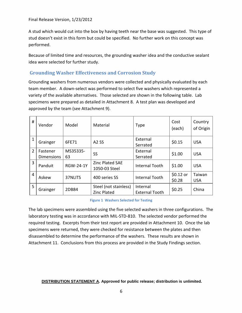
Grounding washers from numerous vendors were collected and physically evaluated by each
team member. A down-select was performed to select five washers which represented a
variety of the available alternatives. Those selected are shown in the following table. Lab
specimens were prepared as detailed in Attachment 8. A test plan was developed and
approved by the team (see Attachment 9).
# Vendor Model Material Type
Cost
(each)
Country
of Origin
1 Grainger 6FE71 A2 SS
External Serrated
$0.15 USA
2 Fastener Dimensions
MS35335-63
SS External Serrated
$1.00 USA
3 Panduit RGW-24-1Y
Zinc Plated SAE 1050-03 Steel
Internal Tooth $1.00 USA
4 Askew 37NLITS 400 series SS Internal Tooth
$0.12 or $0.28
Taiwan USA
5 Grainger 2DB84
Steel (not stainless) Zinc Plated
Internal External Tooth
$0.25 China
Figure 1 Washers Selected for Testing
The lab specimens were assembled using the five selected washers in three configurations. The
laboratory testing was in accordance with MIL-STD-810. The selected vendor performed the
required testing. Excerpts from their test report are provided in Attachment 10. Once the lab
specimens were returned, they were checked for resistance between the plates and then
disassembled to determine the performance of the washers. These results are shown in
Attachment 11. Conclusions from this process are provided in the Study Findings section.
Final Release Version, 1/23/2012
DISTRIBUTION STATEMENT A. Approved for public release; distribution is unlimited.
7
Conductive Sealant Study
Currently, conductive materials are used as a primary mechanism for bonding equipment
frames to the hull structure for Navy programs. The equipment and structure must be properly
prepared by removing any paint and corrosion along the interface. This is usually done by
grinding and sanding just before the equipment is to be permanently installed to prevent
corrosion during the time the equipment is in storage. Attachment 3 identifies multiple
requirements listed in standards that characterize key performance criteria for sealants. Each
standard calls for various characteristics of the sealant. Various conductive sealants were
compared against the requirements of the relevant standards. The conclusions are provided in
the Study Findings section below.
MIL-STD 1310G provides: “A.5.1.3 Enhance conductivity, expel contaminants, retard corrosion. Apply a thin film of MIL-T-22361 antiseize compound to the cleaned areas of the mating surfaces and to the threads of all hardware (bolts and nuts) to be used.
NOTE: Various conductive compounds and paints may be found to serve the same or similar purpose as MIL-T-22361 in this application. Some materials used, including conductive faying material (see A.5.2), might eliminate the need for sealant in accordance with A.5.1.4 and A.5.1.5. Nothing in this MIL-STD should be interpreted as preventing implementation of advancing technology or use of state-of-the-art materials for EMI and corrosion control, enhanced system operation and maintainability and personnel safety.”
This note would allow for the use of other compounds. This note no longer appears in MIL-STD
1310H. Should a new sealant be identified, a change to MIL-STD 1310H would be required.
Study Findings
Grounding Washer Effectiveness and Corrosion Study
Grounding washers, under the conditions of this study, provide a high assurance of an
acceptable ground for safety and EMI concerns. This study was limited to 3/8” bolts, the most
common bolt used for mounting small electrical equipment, but could easily be extended to a
wide variety of small bolt sizes, with low cost additional field testing (demonstration at each
shipyard for additional sizes).
Final Release Version, 1/23/2012
DISTRIBUTION STATEMENT A. Approved for public release; distribution is unlimited.
8
A variety of grounding washers were successful, however stainless steel is recommended for
corrosion prevention. A carbon steel washer would be acceptable in a dry environment. It is
not recommended that specific washers be identified; instead the characteristics of a successful
washer should be specified with examples provided.
Attachment 13 provides a rough order of magnitude (ROM) cost estimate for the potential
savings of using grounding washers in place of the class B bonds. The savings in hours varied
between several thousand hours to more than 18 thousand hours per ship, depending on the
number of grounds converted to the alternative method.
Conductive Sealant Study
Several different sealants were found to have acceptable properties for various applications.
The sealants that were reviewed for applicability are shown. More in depth investigation is
warranted to explore how the sealants perform, ease of application, and wear resistance.
Much of the product information was not available because it is considered proprietary to the
manufacturer. At this time, no change to currently accepted practices and sealants are
recommended.
Pre-Masking Recommendation
Much of the time expended in bonding and ground is in cleaning the surfaces to “bright metal”.
Removal of paint is time consuming, difficult work. Several of the team member suggested
masking of the grounding spots prior to painting. This would work for a Class B (direct contact)
or Class C (grounding strap) bond.
There are several practical considerations that make this recommendation less easy to
implement than it would initially appear. The masking will need to be installed after surface
preparation for paint. Surface preparation of foundations and electrical boxes is either through
blasting or dipping in a corrosive substance. If the masking were installed prior to surface
preparation, much of the masking would be lost. Providing specific directions to the paint
craftsman to install the masking may be difficult. To have an Electrician install the masking
after the surface preparation involves coordination.
During the removal of the masking, after paint, there is a concern that the masking tape will
leave residue. There are many good products that can be used to overcome this concern.
Pre-masking of mating surfaces is recommended to reduce costs for bonding and grounding.
Once the difficulties identified are overcome, a cost savings should result.
Final Release Version, 1/23/2012
DISTRIBUTION STATEMENT A. Approved for public release; distribution is unlimited.
9
Torque Study
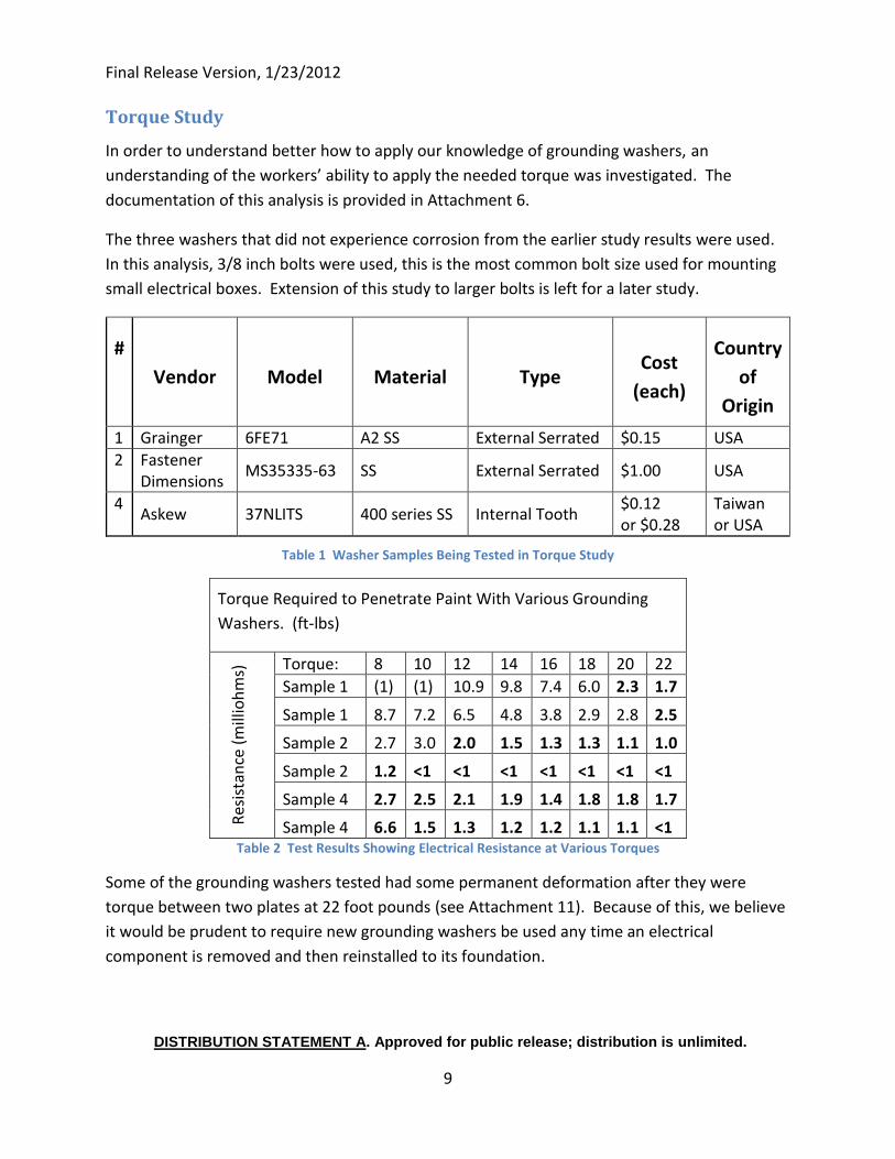
In order to understand better how to apply our knowledge of grounding washers, an
understanding of the workers’ ability to apply the needed torque was investigated. The
documentation of this analysis is provided in Attachment 6.
The three washers that did not experience corrosion from the earlier study results were used.
In this analysis, 3/8 inch bolts were used, this is the most common bolt size used for mounting
small electrical boxes. Extension of this study to larger bolts is left for a later study.
#
Vendor Model Material Type Cost
(each)
Country
of
Origin
1 Grainger 6FE71 A2 SS External Serrated $0.15 USA
2 Fastener Dimensions
MS35335-63 SS External Serrated $1.00 USA
4 Askew 37NLITS 400 series SS Internal Tooth
$0.12 or $0.28
Taiwan or USA
Table 1 Washer Samples Being Tested in Torque Study
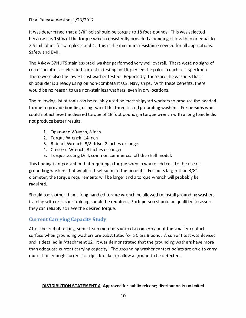
Torque Required to Penetrate Paint With Various Grounding
Washers. (ft-lbs)
Res
ista
nce
(m
illio
hm
s) Torque: 8 10 12 14 16 18 20 22
Sample 1 (1) (1) 10.9 9.8 7.4 6.0 2.3 1.7
Sample 1 8.7 7.2 6.5 4.8 3.8 2.9 2.8 2.5
Sample 2 2.7 3.0 2.0 1.5 1.3 1.3 1.1 1.0
Sample 2 1.2 <1 <1 <1 <1 <1 <1 <1
Sample 4 2.7 2.5 2.1 1.9 1.4 1.8 1.8 1.7
Sample 4 6.6 1.5 1.3 1.2 1.2 1.1 1.1 <1 Table 2 Test Results Showing Electrical Resistance at Various Torques
Some of the grounding washers tested had some permanent deformation after they were
torque between two plates at 22 foot pounds (see Attachment 11). Because of this, we believe
it would be prudent to require new grounding washers be used any time an electrical
component is removed and then reinstalled to its foundation.
Final Release Version, 1/23/2012
DISTRIBUTION STATEMENT A. Approved for public release; distribution is unlimited.
10
It was determined that a 3/8” bolt should be torque to 18 foot-pounds. This was selected
because it is 150% of the torque which consistently provided a bonding of less than or equal to
2.5 milliohms for samples 2 and 4. This is the minimum resistance needed for all applications,
Safety and EMI.
The Askew 37NLITS stainless steel washer performed very well overall. There were no signs of
corrosion after accelerated corrosion testing and it pierced the paint in each test specimen.
These were also the lowest cost washer tested. Reportedly, these are the washers that a
shipbuilder is already using on non-combatant U.S. Navy ships. With these benefits, there
would be no reason to use non-stainless washers, even in dry locations.
The following list of tools can be reliably used by most shipyard workers to produce the needed
torque to provide bonding using two of the three tested grounding washers. For persons who
could not achieve the desired torque of 18 foot pounds, a torque wrench with a long handle did
not produce better results.
1. Open-end Wrench, 8 inch 2. Torque Wrench, 14 inch 3. Ratchet Wrench, 3/8 drive, 8 inches or longer 4. Crescent Wrench, 8 inches or longer 5. Torque-setting Drill, common commercial off the shelf model.
This finding is important in that requiring a torque wrench would add cost to the use of
grounding washers that would off-set some of the benefits. For bolts larger than 3/8”
diameter, the torque requirements will be larger and a torque wrench will probably be
required.
Should tools other than a long handled torque wrench be allowed to install grounding washers,
training with refresher training should be required. Each person should be qualified to assure
they can reliably achieve the desired torque.
Current Carrying Capacity Study
After the end of testing, some team members voiced a concern about the smaller contact
surface when grounding washers are substituted for a Class B bond. A current test was devised
and is detailed in Attachment 12. It was demonstrated that the grounding washers have more
than adequate current carrying capacity. The grounding washer contact points are able to carry
more than enough current to trip a breaker or allow a ground to be detected.
Final Release Version, 1/23/2012
DISTRIBUTION STATEMENT A. Approved for public release; distribution is unlimited.
11
Conclusions and Recommendations
It is recommended that the use of grounding washers in place of cleaning to “Bright Metal” be
allowed in selected applications and under selected controls. Those limits include:
Grounding washers must be 316 grade stainless steel unless another grade of stainless steel is approved in the ship specification.
For 3/8” fasteners, a torque of at least 18 foot pounds is recommended to assure grounding washer piercing of paint/coatings. Each new application of fasteners and washer grounding design must be field tested under the conditions it will be applied using a torque wrench to determine the minimum torque and a micro-ohm meter to verify that the minimum desired ground has been achieved. Once the application is proven to provide a reliable ground, the use of the selected washer and methods can be continued.
The use of anti-seize thread compound zinc dust (A-A-59313) or equivalent is still required on all contact points, which now includes where the grounding washer will pierce the paint/coatings.
If tools other than a calibrated torque wrench are allowed, each worker using alternate tools will require annual training to assure they are achieving the desired torque for that application. Common hand tools were found to develop the required torque for a 3/8” fasteners for a wide variety of shipyard workers.
When a bonded electrical component is removed, new grounding washers are required for re-installation.
Allowing the use of grounding washers as an alternative method for grounding will require a
change to MIL-STD 1310.
Adding a separate grounding conductor, for individual electrical components should be
considered in substitution for other grounding methods. The benefit is reduced time for
grounding and a better opportunity for using plugs for connecting electrical components. The
potential negative impacts are added costs and weight for the cables because of the additional
conductor. Allowing for using a separate grounding conductor will require changes to MIL-STD
1310.
It is recommended that each shipyard explore pre-masking grounding surfaces on electrical
foundations and electrical equipment. Although there are potential cost benefits, the
complications discussed herein make this a complex decision. This recommendation requires
no change to MIL-STD 1310.
Final Release Version, 1/23/2012
DISTRIBUTION STATEMENT A. Approved for public release; distribution is unlimited.
12
No change to existing requirements for conductive sealants is recommended. Additional study
using the criteria discussed in Attachment 3 could result in new products, however none were
discovered during this limited study.
Proposed changes to MIL-STD 1310 for bonding and grounding were developed and are
presented in Attachment 4.
Final Release Version, 1/23/2012
DISTRIBUTION STATEMENT A. Approved for public release; distribution is unlimited.
1
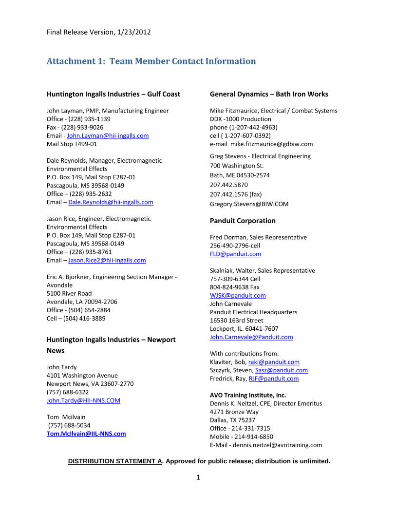
Attachment 1: Team Member Contact Information
Huntington Ingalls Industries – Gulf Coast
John Layman, PMP, Manufacturing Engineer Office - (228) 935-1139 Fax - (228) 933-9026 Email - [email protected] Mail Stop T499-01 Dale Reynolds, Manager, Electromagnetic Environmental Effects P.O. Box 149, Mail Stop E287-01 Pascagoula, MS 39568-0149 Office – (228) 935-2632 Email – [email protected] Jason Rice, Engineer, Electromagnetic Environmental Effects P.O. Box 149, Mail Stop E287-01 Pascagoula, MS 39568-0149 Office – (228) 935-8761 Email – [email protected] Eric A. Bjorkner, Engineering Section Manager - Avondale 5100 River Road Avondale, LA 70094-2706 Office - (504) 654-2884 Cell – (504) 416-3889
Huntington Ingalls Industries – Newport
News
John Tardy 4101 Washington Avenue Newport News, VA 23607-2770 (757) 688-6322 [email protected] Tom Mcilvain (757) 688-5034 [email protected]
General Dynamics – Bath Iron Works
Mike Fitzmaurice, Electrical / Combat Systems DDX -1000 Production phone (1-207-442-4963) cell ( 1-207-607-0392) e-mail [email protected]
Greg Stevens - Electrical Engineering
700 Washington St.
Bath, ME 04530-2574
207.442.5870
207.442.1576 (fax)
Panduit Corporation
Fred Dorman, Sales Representative 256-490-2796-cell [email protected] Skalniak, Walter, Sales Representative 757-309-6344 Cell 804-824-9638 Fax [email protected] John Carnevale Panduit Electrical Headquarters 16530 163rd Street Lockport, IL. 60441-7607 [email protected] With contributions from: Klaviter, Bob, [email protected] Szczyrk, Steven, [email protected] Fredrick, Ray, [email protected] AVO Training Institute, Inc. Dennis K. Neitzel, CPE, Director Emeritus 4271 Bronze Way Dallas, TX 75237 Office - 214-331-7315 Mobile - 214-914-6850 E-Mail - [email protected]
Final Release Version, 1/23/2012
DISTRIBUTION STATEMENT A. Approved for public release; distribution is unlimited.
1
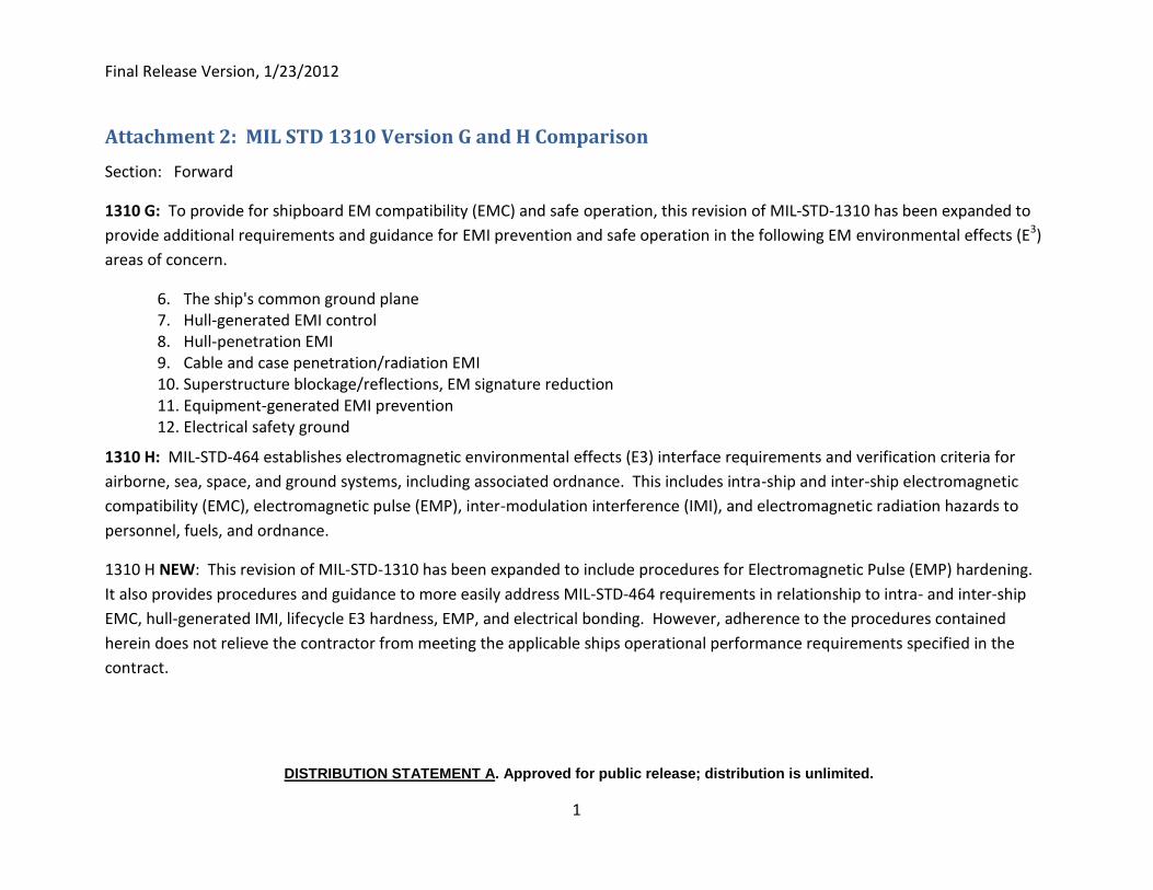
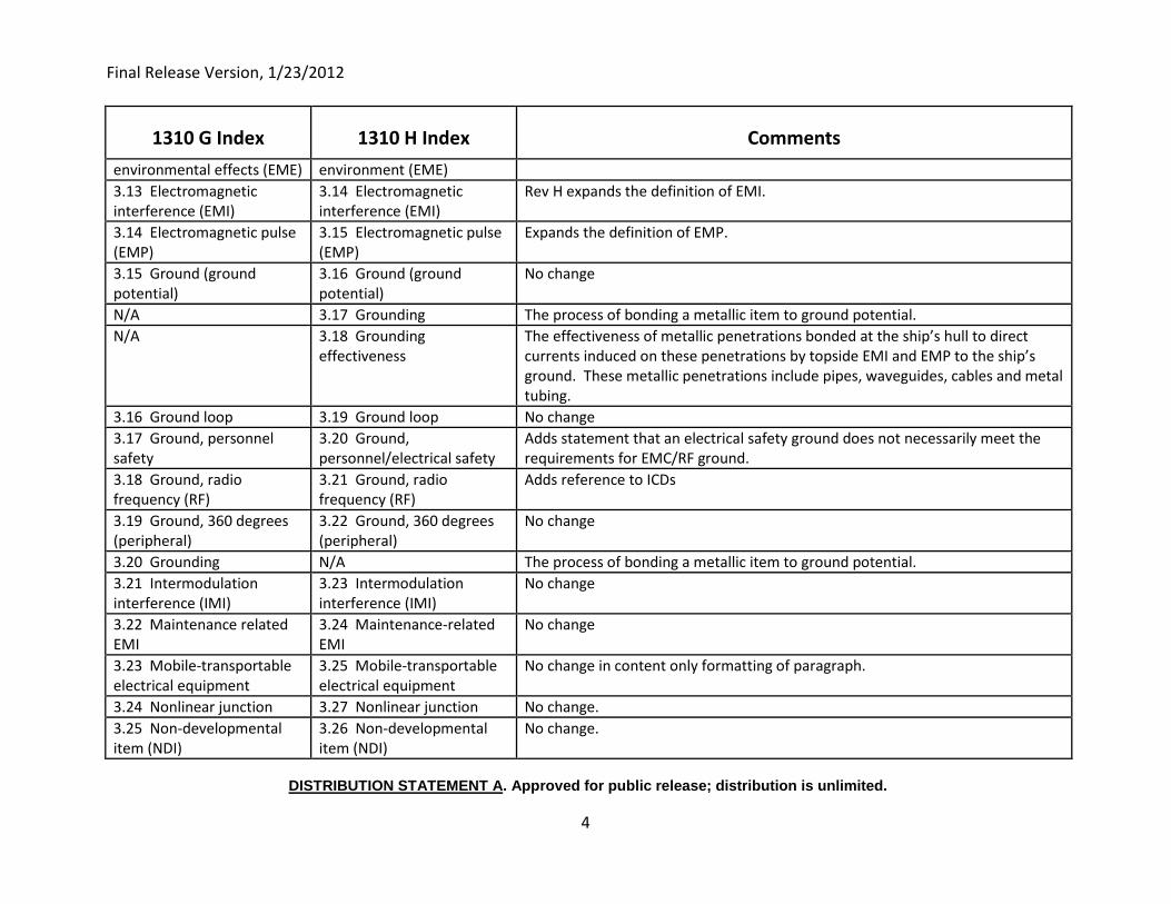
Attachment 2: MIL STD 1310 Version G and H Comparison
Section: Forward
1310 G: To provide for shipboard EM compatibility (EMC) and safe operation, this revision of MIL-STD-1310 has been expanded to
provide additional requirements and guidance for EMI prevention and safe operation in the following EM environmental effects (E3)
areas of concern.
6. The ship's common ground plane 7. Hull-generated EMI control 8. Hull-penetration EMI 9. Cable and case penetration/radiation EMI 10. Superstructure blockage/reflections, EM signature reduction 11. Equipment-generated EMI prevention 12. Electrical safety ground
1310 H: MIL-STD-464 establishes electromagnetic environmental effects (E3) interface requirements and verification criteria for
airborne, sea, space, and ground systems, including associated ordnance. This includes intra-ship and inter-ship electromagnetic
compatibility (EMC), electromagnetic pulse (EMP), inter-modulation interference (IMI), and electromagnetic radiation hazards to
personnel, fuels, and ordnance.
1310 H NEW: This revision of MIL-STD-1310 has been expanded to include procedures for Electromagnetic Pulse (EMP) hardening.
It also provides procedures and guidance to more easily address MIL-STD-464 requirements in relationship to intra- and inter-ship
EMC, hull-generated IMI, lifecycle E3 hardness, EMP, and electrical bonding. However, adherence to the procedures contained
herein does not relieve the contractor from meeting the applicable ships operational performance requirements specified in the
contract.
Final Release Version, 1/23/2012
DISTRIBUTION STATEMENT A. Approved for public release; distribution is unlimited.
2
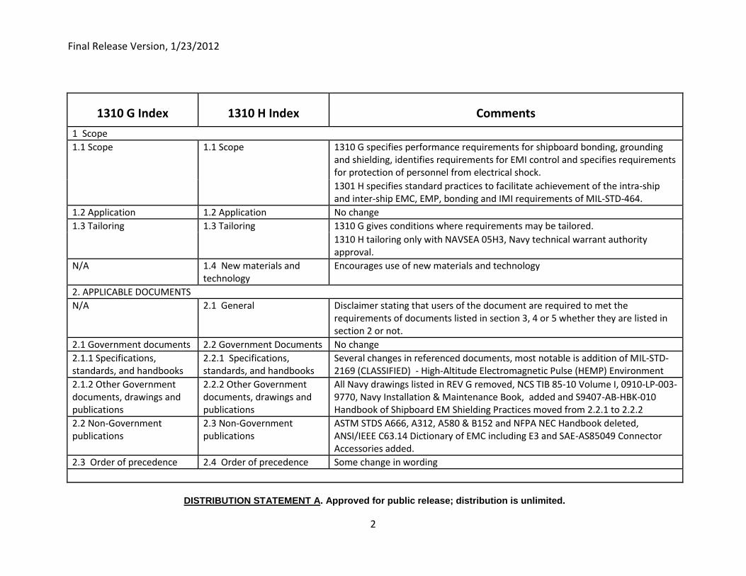
1310 G Index 1310 H Index Comments
1 Scope
1.1 Scope 1.1 Scope 1310 G specifies performance requirements for shipboard bonding, grounding and shielding, identifies requirements for EMI control and specifies requirements for protection of personnel from electrical shock.
1301 H specifies standard practices to facilitate achievement of the intra-ship and inter-ship EMC, EMP, bonding and IMI requirements of MIL-STD-464.
1.2 Application 1.2 Application No change
1.3 Tailoring 1.3 Tailoring 1310 G gives conditions where requirements may be tailored.
1310 H tailoring only with NAVSEA 05H3, Navy technical warrant authority approval.
N/A 1.4 New materials and technology
Encourages use of new materials and technology
2. APPLICABLE DOCUMENTS
N/A 2.1 General Disclaimer stating that users of the document are required to met the requirements of documents listed in section 3, 4 or 5 whether they are listed in section 2 or not.
2.1 Government documents 2.2 Government Documents No change
2.1.1 Specifications, standards, and handbooks
2.2.1 Specifications, standards, and handbooks
Several changes in referenced documents, most notable is addition of MIL-STD-2169 (CLASSIFIED) - High-Altitude Electromagnetic Pulse (HEMP) Environment
2.1.2 Other Government documents, drawings and publications
2.2.2 Other Government documents, drawings and publications
All Navy drawings listed in REV G removed, NCS TIB 85-10 Volume I, 0910-LP-003-9770, Navy Installation & Maintenance Book, added and S9407-AB-HBK-010 Handbook of Shipboard EM Shielding Practices moved from 2.2.1 to 2.2.2
2.2 Non-Government publications
2.3 Non-Government publications
ASTM STDS A666, A312, A580 & B152 and NFPA NEC Handbook deleted, ANSI/IEEE C63.14 Dictionary of EMC including E3 and SAE-AS85049 Connector Accessories added.
2.3 Order of precedence 2.4 Order of precedence Some change in wording
Final Release Version, 1/23/2012
DISTRIBUTION STATEMENT A. Approved for public release; distribution is unlimited.
3
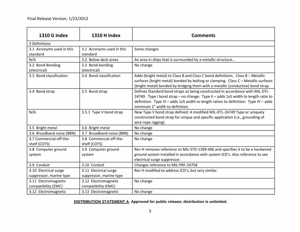
1310 G Index 1310 H Index Comments
3 Definitions
3.1 Acronyms used in this standard
3.1 Acronyms used in this standard
Some changes
N/A 3.2 Below deck areas An area in ships that is surrounded by a metallic structure…
3.2 Bond-Bonding (electrical)
3.3 Bond-bonding (electrical)
No change
3.3 Bond classification 3.4 Bond classification Adds (bright metal) to Class B and Class C bond definitions. Class B – Metallic surfaces (bright metal) bonded by bolting or clamping. Class C – Metallic surfaces (bright metal) bonded by bridging them with a metallic (conductive) bond strap.
3.4 Bond strap 3.5 Bond strap Defines Standard bond straps as being constructed in accordance with MIL-DTL-24749. Type I bond strap – no change: Type II – adds 1x5 width to length ratio to definition: Type III – adds 1x5 width to length ration to definition: Type IV – adds minimum 1” width to definition.
N/A 3.5.1 Type V bond strap New Type V bond strap defined: A modified MIL-DTL-24749 Type or uniquely constructed bond strap for unique and specific application (i.e., grounding of wire rope rigging).
3.5 Bright metal 3.6 Bright metal No change
3.6 Broadband noise (BBN) 3.7 Broadband noise (BBN) No change
3.7 Commercial-off-the-shelf (COTS)
3.8 Commercial-off-the-shelf (COTS)
No change
3.8 Computer ground system
3.9 Computer ground system
Rev H removes reference to MIL-STD-1399-406 and specifies it to be a hardwired ground system installed in accordance with system ICD’s. Also reference to see electrical surge suppressor.
3.9 Conduit 3.10 Conduit Changes reference to MIL-PRF-24758
3.10 Electrical surge suppressor, marine type
3.11 Electrical surge suppressor, marine type
Rev H modified to address ICD’s, but very similar.
3.11 Electromagnetic compatibility (EMC)
3.12 Electromagnetic compatibility (EMC)
No change
3.12 Electromagnetic 3.13 Electromagnetic No change
Final Release Version, 1/23/2012
DISTRIBUTION STATEMENT A. Approved for public release; distribution is unlimited.
4
1310 G Index 1310 H Index Comments
environmental effects (EME) environment (EME)
3.13 Electromagnetic interference (EMI)
3.14 Electromagnetic interference (EMI)
Rev H expands the definition of EMI.
3.14 Electromagnetic pulse (EMP)
3.15 Electromagnetic pulse (EMP)
Expands the definition of EMP.
3.15 Ground (ground potential)
3.16 Ground (ground potential)
No change
N/A 3.17 Grounding The process of bonding a metallic item to ground potential.
N/A 3.18 Grounding effectiveness
The effectiveness of metallic penetrations bonded at the ship’s hull to direct currents induced on these penetrations by topside EMI and EMP to the ship’s ground. These metallic penetrations include pipes, waveguides, cables and metal tubing.
3.16 Ground loop 3.19 Ground loop No change
3.17 Ground, personnel safety
3.20 Ground, personnel/electrical safety
Adds statement that an electrical safety ground does not necessarily meet the requirements for EMC/RF ground.
3.18 Ground, radio frequency (RF)
3.21 Ground, radio frequency (RF)
Adds reference to ICDs
3.19 Ground, 360 degrees (peripheral)
3.22 Ground, 360 degrees (peripheral)
No change
3.20 Grounding N/A The process of bonding a metallic item to ground potential.
3.21 Intermodulation interference (IMI)
3.23 Intermodulation interference (IMI)
No change
3.22 Maintenance related EMI
3.24 Maintenance-related EMI
No change
3.23 Mobile-transportable electrical equipment
3.25 Mobile-transportable electrical equipment
No change in content only formatting of paragraph.
3.24 Nonlinear junction 3.27 Nonlinear junction No change.
3.25 Non-developmental item (NDI)
3.26 Non-developmental item (NDI)
No change.
Final Release Version, 1/23/2012
DISTRIBUTION STATEMENT A. Approved for public release; distribution is unlimited.
5
1310 G Index 1310 H Index Comments
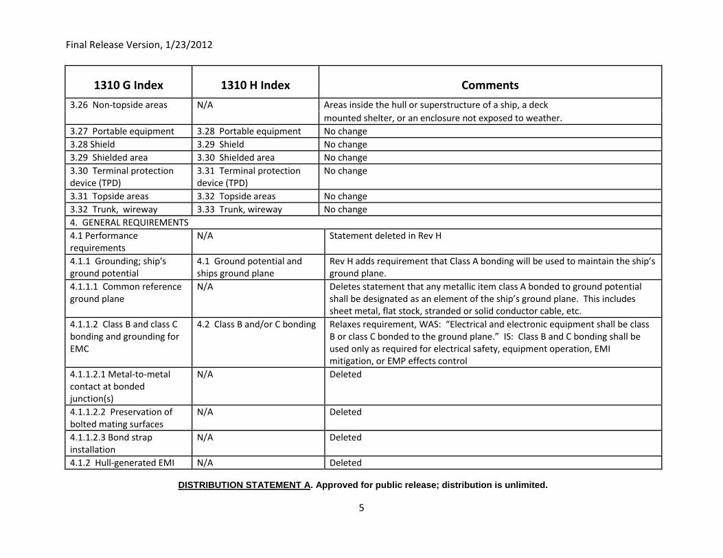
3.26 Non-topside areas N/A Areas inside the hull or superstructure of a ship, a deck
mounted shelter, or an enclosure not exposed to weather.
3.27 Portable equipment 3.28 Portable equipment No change
3.28 Shield 3.29 Shield No change
3.29 Shielded area 3.30 Shielded area No change
3.30 Terminal protection device (TPD)
3.31 Terminal protection device (TPD)
No change
3.31 Topside areas 3.32 Topside areas No change
3.32 Trunk, wireway 3.33 Trunk, wireway No change
4. GENERAL REQUIREMENTS
4.1 Performance requirements
N/A Statement deleted in Rev H
4.1.1 Grounding; ship's ground potential
4.1 Ground potential and ships ground plane
Rev H adds requirement that Class A bonding will be used to maintain the ship’s ground plane.
4.1.1.1 Common reference ground plane
N/A Deletes statement that any metallic item class A bonded to ground potential shall be designated as an element of the ship’s ground plane. This includes sheet metal, flat stock, stranded or solid conductor cable, etc.
4.1.1.2 Class B and class C bonding and grounding for EMC
4.2 Class B and/or C bonding Relaxes requirement, WAS: “Electrical and electronic equipment shall be class B or class C bonded to the ground plane.” IS: Class B and C bonding shall be used only as required for electrical safety, equipment operation, EMI mitigation, or EMP effects control
4.1.1.2.1 Metal-to-metal contact at bonded junction(s)
N/A Deleted
4.1.1.2.2 Preservation of bolted mating surfaces
N/A Deleted
4.1.1.2.3 Bond strap installation
N/A Deleted
4.1.2 Hull-generated EMI N/A Deleted
Final Release Version, 1/23/2012
DISTRIBUTION STATEMENT A. Approved for public release; distribution is unlimited.
6
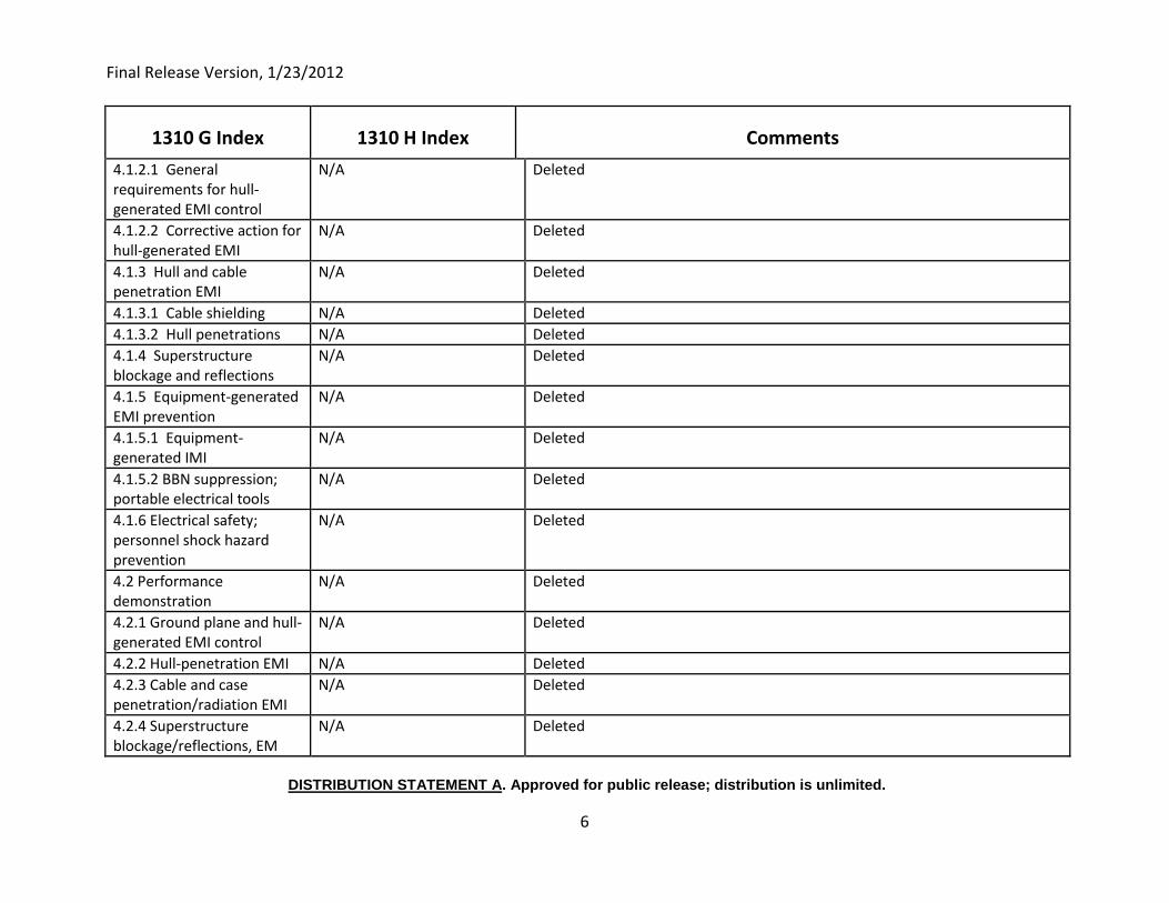
1310 G Index 1310 H Index Comments
4.1.2.1 General requirements for hull-generated EMI control
N/A Deleted
4.1.2.2 Corrective action for hull-generated EMI
N/A Deleted
4.1.3 Hull and cable penetration EMI
N/A Deleted
4.1.3.1 Cable shielding N/A Deleted
4.1.3.2 Hull penetrations N/A Deleted
4.1.4 Superstructure blockage and reflections
N/A Deleted
4.1.5 Equipment-generated EMI prevention
N/A Deleted
4.1.5.1 Equipment-generated IMI
N/A Deleted
4.1.5.2 BBN suppression; portable electrical tools
N/A Deleted
4.1.6 Electrical safety; personnel shock hazard prevention
N/A Deleted
4.2 Performance demonstration
N/A Deleted
4.2.1 Ground plane and hull-generated EMI control
N/A Deleted
4.2.2 Hull-penetration EMI N/A Deleted
4.2.3 Cable and case penetration/radiation EMI
N/A Deleted
4.2.4 Superstructure blockage/reflections, EM
N/A Deleted
Final Release Version, 1/23/2012
DISTRIBUTION STATEMENT A. Approved for public release; distribution is unlimited.
7
1310 G Index 1310 H Index Comments
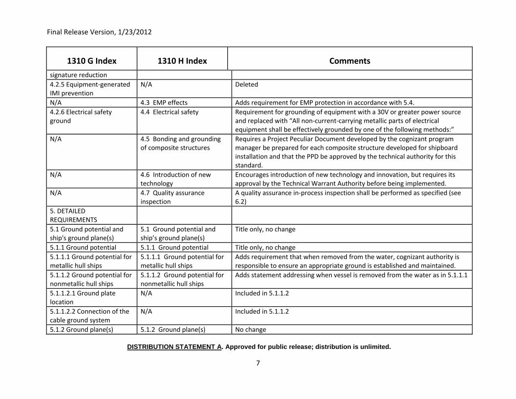
signature reduction
4.2.5 Equipment-generated IMI prevention
N/A Deleted
N/A 4.3 EMP effects Adds requirement for EMP protection in accordance with 5.4.
4.2.6 Electrical safety ground
4.4 Electrical safety Requirement for grounding of equipment with a 30V or greater power source and replaced with “All non-current-carrying metallic parts of electrical equipment shall be effectively grounded by one of the following methods:”
N/A 4.5 Bonding and grounding of composite structures
Requires a Project Peculiar Document developed by the cognizant program manager be prepared for each composite structure developed for shipboard installation and that the PPD be approved by the technical authority for this standard.
N/A 4.6 Introduction of new technology
Encourages introduction of new technology and innovation, but requires its approval by the Technical Warrant Authority before being implemented.
N/A 4.7 Quality assurance inspection
A quality assurance in-process inspection shall be performed as specified (see 6.2)
5. DETAILED REQUIREMENTS
5.1 Ground potential and ship's ground plane(s)
5.1 Ground potential and ship’s ground plane(s)
Title only, no change
5.1.1 Ground potential 5.1.1 Ground potential Title only, no change
5.1.1.1 Ground potential for metallic hull ships
5.1.1.1 Ground potential for metallic hull ships
Adds requirement that when removed from the water, cognizant authority is responsible to ensure an appropriate ground is established and maintained.
5.1.1.2 Ground potential for nonmetallic hull ships
5.1.1.2 Ground potential for nonmetallic hull ships
Adds statement addressing when vessel is removed from the water as in 5.1.1.1
5.1.1.2.1 Ground plate location
N/A Included in 5.1.1.2
5.1.1.2.2 Connection of the cable ground system
N/A Included in 5.1.1.2
5.1.2 Ground plane(s) 5.1.2 Ground plane(s) No change
Final Release Version, 1/23/2012
DISTRIBUTION STATEMENT A. Approved for public release; distribution is unlimited.
8
1310 G Index 1310 H Index Comments
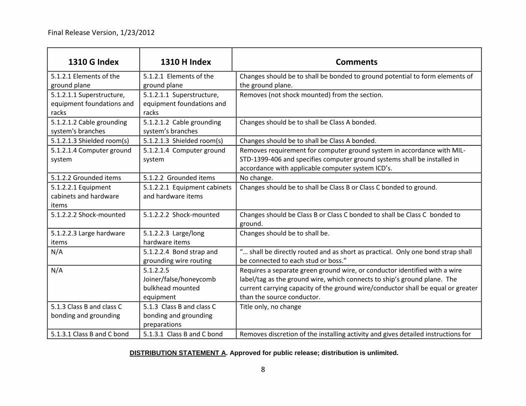
5.1.2.1 Elements of the ground plane
5.1.2.1 Elements of the ground plane
Changes should be to shall be bonded to ground potential to form elements of the ground plane.
5.1.2.1.1 Superstructure, equipment foundations and racks
5.1.2.1.1 Superstructure, equipment foundations and racks
Removes (not shock mounted) from the section.
5.1.2.1.2 Cable grounding system's branches
5.1.2.1.2 Cable grounding system’s branches
Changes should be to shall be Class A bonded.
5.1.2.1.3 Shielded room(s) 5.1.2.1.3 Shielded room(s) Changes should be to shall be Class A bonded.
5.1.2.1.4 Computer ground system
5.1.2.1.4 Computer ground system
Removes requirement for computer ground system in accordance with MIL-STD-1399-406 and specifies computer ground systems shall be installed in accordance with applicable computer system ICD’s.
5.1.2.2 Grounded items 5.1.2.2 Grounded items No change.
5.1.2.2.1 Equipment cabinets and hardware items
5.1.2.2.1 Equipment cabinets and hardware items
Changes should be to shall be Class B or Class C bonded to ground.
5.1.2.2.2 Shock-mounted 5.1.2.2.2 Shock-mounted Changes should be Class B or Class C bonded to shall be Class C bonded to ground.
5.1.2.2.3 Large hardware items
5.1.2.2.3 Large/long hardware items
Changes should be to shall be.
N/A 5.1.2.2.4 Bond strap and grounding wire routing
“… shall be directly routed and as short as practical. Only one bond strap shall be connected to each stud or boss.”
N/A 5.1.2.2.5 Joiner/false/honeycomb bulkhead mounted equipment
Requires a separate green ground wire, or conductor identified with a wire label/tag as the ground wire, which connects to ship’s ground plane. The current carrying capacity of the ground wire/conductor shall be equal or greater than the source conductor.
5.1.3 Class B and class C bonding and grounding
5.1.3 Class B and class C bonding and grounding preparations
Title only, no change
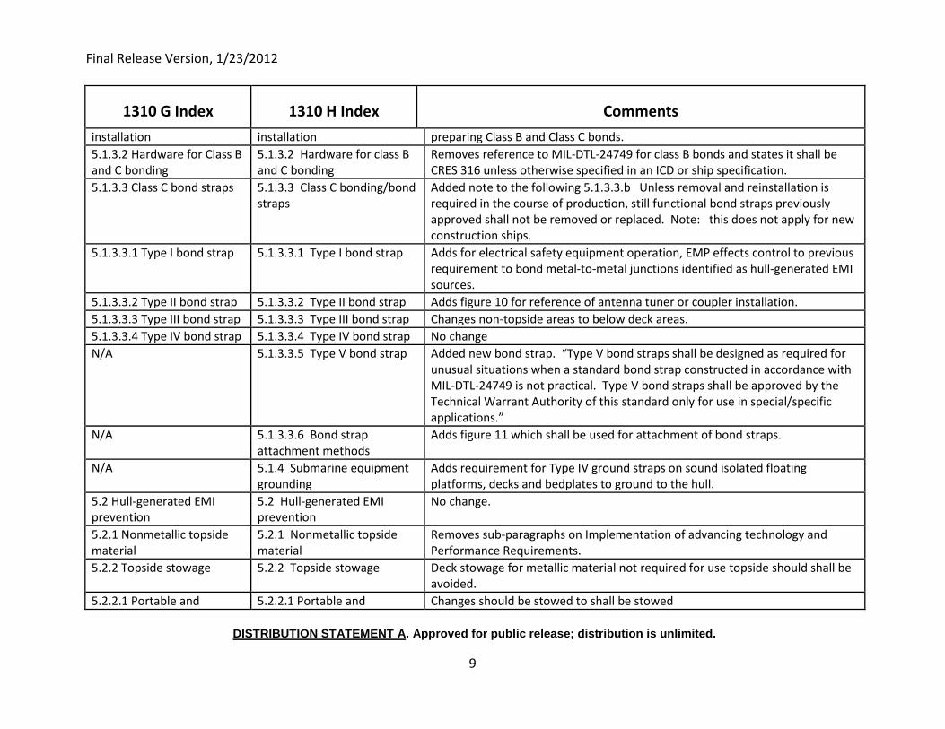
5.1.3.1 Class B and C bond 5.1.3.1 Class B and C bond Removes discretion of the installing activity and gives detailed instructions for
Final Release Version, 1/23/2012
DISTRIBUTION STATEMENT A. Approved for public release; distribution is unlimited.
9
1310 G Index 1310 H Index Comments
installation installation preparing Class B and Class C bonds.
5.1.3.2 Hardware for Class B and C bonding
5.1.3.2 Hardware for class B and C bonding
Removes reference to MIL-DTL-24749 for class B bonds and states it shall be CRES 316 unless otherwise specified in an ICD or ship specification.
5.1.3.3 Class C bond straps 5.1.3.3 Class C bonding/bond straps
Added note to the following 5.1.3.3.b Unless removal and reinstallation is required in the course of production, still functional bond straps previously approved shall not be removed or replaced. Note: this does not apply for new construction ships.
5.1.3.3.1 Type I bond strap 5.1.3.3.1 Type I bond strap Adds for electrical safety equipment operation, EMP effects control to previous requirement to bond metal-to-metal junctions identified as hull-generated EMI sources.
5.1.3.3.2 Type II bond strap 5.1.3.3.2 Type II bond strap Adds figure 10 for reference of antenna tuner or coupler installation.
5.1.3.3.3 Type III bond strap 5.1.3.3.3 Type III bond strap Changes non-topside areas to below deck areas.
5.1.3.3.4 Type IV bond strap 5.1.3.3.4 Type IV bond strap No change
N/A 5.1.3.3.5 Type V bond strap Added new bond strap. “Type V bond straps shall be designed as required for unusual situations when a standard bond strap constructed in accordance with MIL-DTL-24749 is not practical. Type V bond straps shall be approved by the Technical Warrant Authority of this standard only for use in special/specific applications.”
N/A 5.1.3.3.6 Bond strap attachment methods
Adds figure 11 which shall be used for attachment of bond straps.
N/A 5.1.4 Submarine equipment grounding
Adds requirement for Type IV ground straps on sound isolated floating platforms, decks and bedplates to ground to the hull.
5.2 Hull-generated EMI prevention
5.2 Hull-generated EMI prevention
No change.
5.2.1 Nonmetallic topside material
5.2.1 Nonmetallic topside material
Removes sub-paragraphs on Implementation of advancing technology and Performance Requirements.
5.2.2 Topside stowage 5.2.2 Topside stowage Deck stowage for metallic material not required for use topside should shall be avoided.
5.2.2.1 Portable and 5.2.2.1 Portable and Changes should be stowed to shall be stowed
Final Release Version, 1/23/2012
DISTRIBUTION STATEMENT A. Approved for public release; distribution is unlimited.
10
1310 G Index 1310 H Index Comments
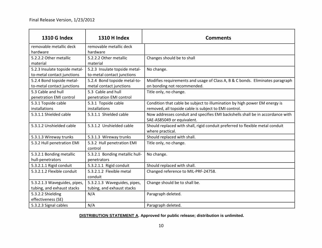
removable metallic deck hardware
removable metallic deck hardware
5.2.2.2 Other metallic material
5.2.2.2 Other metallic material
Changes should be to shall
5.2.3 Insulate topside metal-to-metal contact junctions
5.2.3 Insulate topside metal-to-metal contact junctions
No change.
5.2.4 Bond topside metal-to-metal contact junctions
5.2.4 Bond topside metal-to-metal contact junctions
Modifies requirements and usage of Class A, B & C bonds. Eliminates paragraph on bonding not recommended.
5.3 Cable and hull penetration EMI control
5.3 Cable and hull penetration EMI control
Title only, no change.
5.3.1 Topside cable installations
5.3.1 Topside cable installations
Condition that cable be subject to illumination by high power EM energy is removed, all topside cable is subject to EMI control.
5.3.1.1 Shielded cable 5.3.1.1 Shielded cable Now addresses conduit and specifies EMI backshells shall be in accordance with SAE-AS85049 or equivalent.
5.3.1.2 Unshielded cable 5.3.1.2 Unshielded cable Should replaced with shall, rigid conduit preferred to flexible metal conduit where practical.
5.3.1.3 Wireway trunks 5.3.1.3 Wireway trunks Should replaced with shall.
5.3.2 Hull penetration EMI 5.3.2 Hull penetration EMI control
Title only, no change.
5.3.2.1 Bonding metallic hull-penetrators
5.3.2.1 Bonding metallic hull-penetrators
No change.
5.3.2.1.1 Rigid conduit 5.3.2.1.1 Rigid conduit Should replaced with shall.
5.3.2.1.2 Flexible conduit 5.3.2.1.2 Flexible metal conduit
Changed reference to MIL-PRF-24758.
5.3.2.1.3 Waveguides, pipes, tubing, and exhaust stacks
5.3.2.1.3 Waveguides, pipes, tubing, and exhaust stacks
Change should be to shall be.
5.3.2.2 Shielding effectiveness (SE)
N/A Paragraph deleted.
5.3.2.3 Signal cables N/A Paragraph deleted.
Final Release Version, 1/23/2012
DISTRIBUTION STATEMENT A. Approved for public release; distribution is unlimited.
11
1310 G Index 1310 H Index Comments
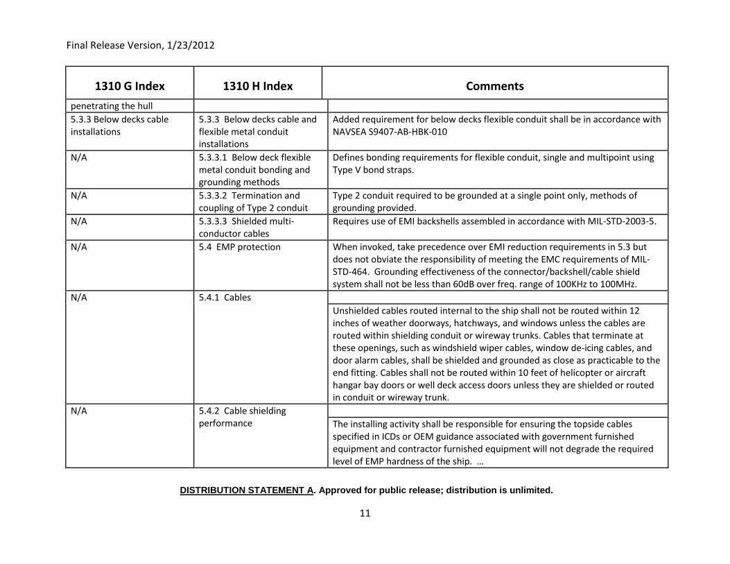
penetrating the hull
5.3.3 Below decks cable installations
5.3.3 Below decks cable and flexible metal conduit installations
Added requirement for below decks flexible conduit shall be in accordance with NAVSEA S9407-AB-HBK-010
N/A 5.3.3.1 Below deck flexible metal conduit bonding and grounding methods
Defines bonding requirements for flexible conduit, single and multipoint using Type V bond straps.
N/A 5.3.3.2 Termination and coupling of Type 2 conduit
Type 2 conduit required to be grounded at a single point only, methods of grounding provided.
N/A 5.3.3.3 Shielded multi-conductor cables
Requires use of EMI backshells assembled in accordance with MIL-STD-2003-5.
N/A 5.4 EMP protection When invoked, take precedence over EMI reduction requirements in 5.3 but does not obviate the responsibility of meeting the EMC requirements of MIL-STD-464. Grounding effectiveness of the connector/backshell/cable shield system shall not be less than 60dB over freq. range of 100KHz to 100MHz.
N/A 5.4.1 Cables
Unshielded cables routed internal to the ship shall not be routed within 12 inches of weather doorways, hatchways, and windows unless the cables are routed within shielding conduit or wireway trunks. Cables that terminate at these openings, such as windshield wiper cables, window de-icing cables, and door alarm cables, shall be shielded and grounded as close as practicable to the end fitting. Cables shall not be routed within 10 feet of helicopter or aircraft hangar bay doors or well deck access doors unless they are shielded or routed in conduit or wireway trunk.
N/A 5.4.2 Cable shielding performance
The installing activity shall be responsible for ensuring the topside cables specified in ICDs or OEM guidance associated with government furnished equipment and contractor furnished equipment will not degrade the required level of EMP hardness of the ship. …
Final Release Version, 1/23/2012
DISTRIBUTION STATEMENT A. Approved for public release; distribution is unlimited.
12
1310 G Index 1310 H Index Comments
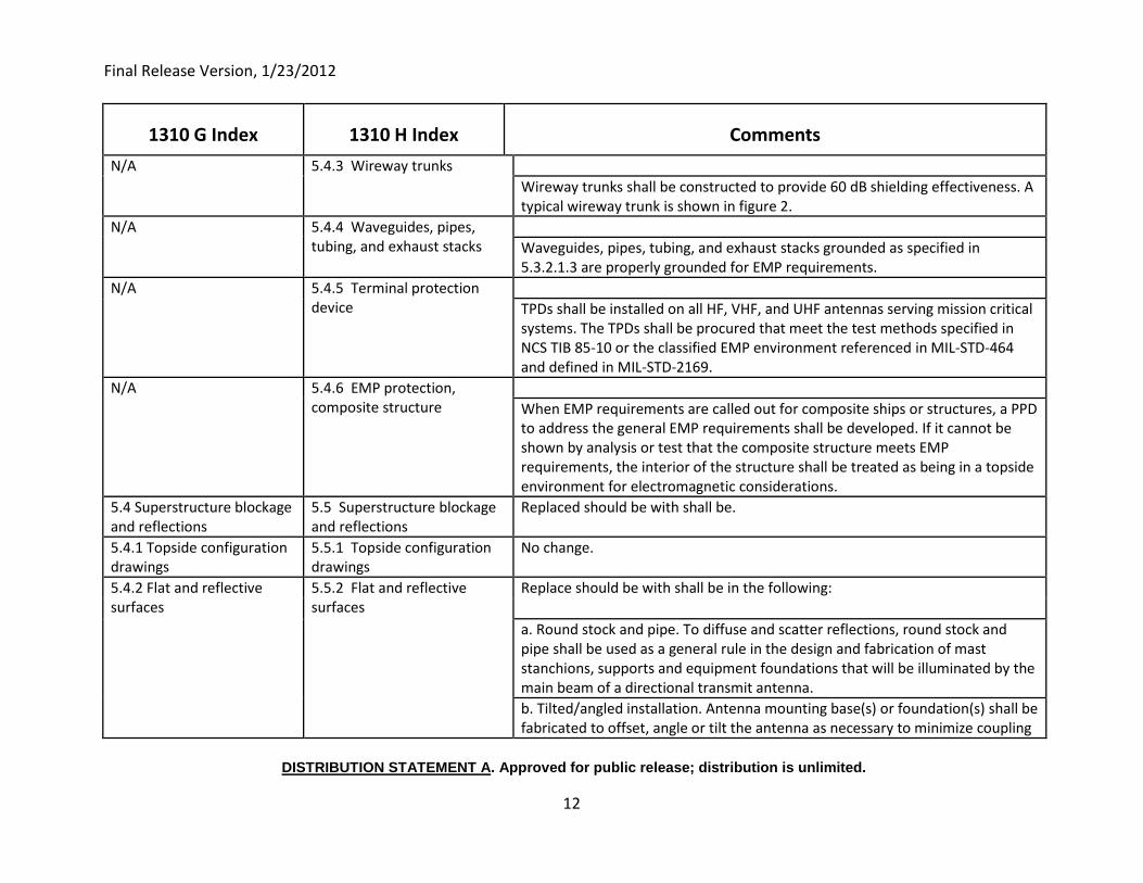
N/A 5.4.3 Wireway trunks
Wireway trunks shall be constructed to provide 60 dB shielding effectiveness. A typical wireway trunk is shown in figure 2.
N/A 5.4.4 Waveguides, pipes, tubing, and exhaust stacks
Waveguides, pipes, tubing, and exhaust stacks grounded as specified in 5.3.2.1.3 are properly grounded for EMP requirements.
N/A 5.4.5 Terminal protection device
TPDs shall be installed on all HF, VHF, and UHF antennas serving mission critical systems. The TPDs shall be procured that meet the test methods specified in NCS TIB 85-10 or the classified EMP environment referenced in MIL-STD-464 and defined in MIL-STD-2169.
N/A 5.4.6 EMP protection, composite structure
When EMP requirements are called out for composite ships or structures, a PPD to address the general EMP requirements shall be developed. If it cannot be shown by analysis or test that the composite structure meets EMP requirements, the interior of the structure shall be treated as being in a topside environment for electromagnetic considerations.
5.4 Superstructure blockage and reflections
5.5 Superstructure blockage and reflections
Replaced should be with shall be.
5.4.1 Topside configuration drawings
5.5.1 Topside configuration drawings
No change.
5.4.2 Flat and reflective surfaces
5.5.2 Flat and reflective surfaces
Replace should be with shall be in the following:
a. Round stock and pipe. To diffuse and scatter reflections, round stock and pipe shall be used as a general rule in the design and fabrication of mast stanchions, supports and equipment foundations that will be illuminated by the main beam of a directional transmit antenna.
b. Tilted/angled installation. Antenna mounting base(s) or foundation(s) shall be fabricated to offset, angle or tilt the antenna as necessary to minimize coupling
Final Release Version, 1/23/2012
DISTRIBUTION STATEMENT A. Approved for public release; distribution is unlimited.
13
1310 G Index 1310 H Index Comments
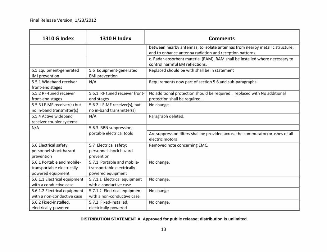
between nearby antennas; to isolate antennas from nearby metallic structure; and to enhance antenna radiation and reception patterns.
c. Radar-absorbent material (RAM). RAM shall be installed where necessary to control harmful EM reflections.
5.5 Equipment-generated IMI prevention
5.6 Equipment-generated EMI prevention
Replaced should be with shall be in statement
5.5.1 Wideband receiver front-end stages
N/A Requirements now part of section 5.6 and sub-paragraphs.
5.5.2 RF-tuned receiver front-end stages
5.6.1 RF tuned receiver front-end stages
No additional protection should be required… replaced with No additional protection shall be required…
5.5.3 LF-MF receiver(s) but no in-band transmitter(s)
5.6.2 LF-MF receiver(s), but no in-band transmitter(s)
No change.
5.5.4 Active wideband receiver coupler systems
N/A Paragraph deleted.
N/A 5.6.3 BBN suppression; portable electrical tools
Arc suppression filters shall be provided across the commutator/brushes of all electric motors
5.6 Electrical safety; personnel shock hazard prevention
5.7 Electrical safety; personnel shock hazard prevention
Removed note concerning EMC.
5.6.1 Portable and mobile-transportable electrically-powered equipment
5.7.1 Portable and mobile-transportable electrically-powered equipment
No change.
5.6.1.1 Electrical equipment with a conductive case
5.7.1.1 Electrical equipment with a conductive case
No change.
5.6.1.2 Electrical equipment with a non-conductive case
5.7.1.2 Electrical equipment with a non-conductive case
No change
5.6.2 Fixed-installed, electrically-powered
5.7.2 Fixed-installed, electrically-powered
No change.
Final Release Version, 1/23/2012
DISTRIBUTION STATEMENT A. Approved for public release; distribution is unlimited.
14
1310 G Index 1310 H Index Comments
equipment equipment
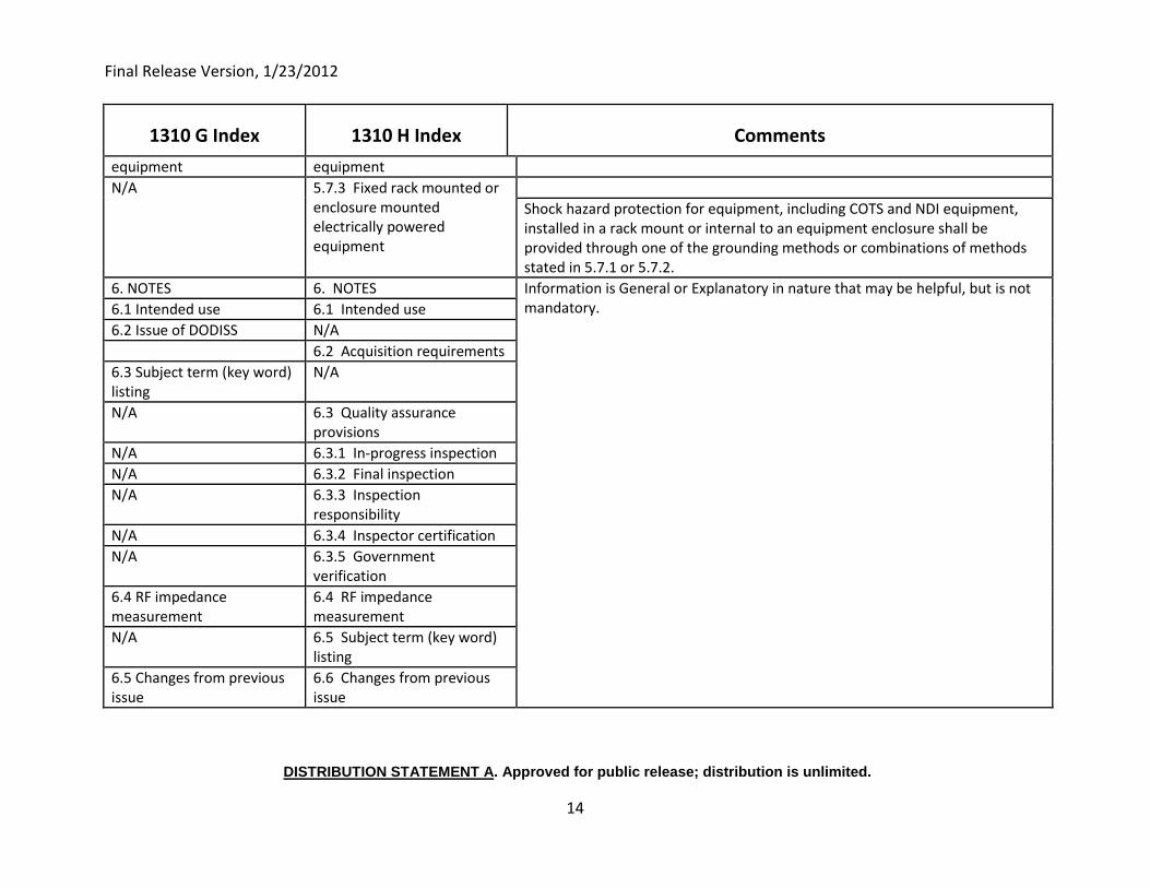
N/A 5.7.3 Fixed rack mounted or enclosure mounted electrically powered equipment
Shock hazard protection for equipment, including COTS and NDI equipment, installed in a rack mount or internal to an equipment enclosure shall be provided through one of the grounding methods or combinations of methods stated in 5.7.1 or 5.7.2.
6. NOTES 6. NOTES Information is General or Explanatory in nature that may be helpful, but is not mandatory. 6.1 Intended use 6.1 Intended use
6.2 Issue of DODISS N/A
6.2 Acquisition requirements
6.3 Subject term (key word) listing
N/A
N/A 6.3 Quality assurance provisions
N/A 6.3.1 In-progress inspection
N/A 6.3.2 Final inspection
N/A 6.3.3 Inspection responsibility
N/A 6.3.4 Inspector certification
N/A 6.3.5 Government verification
6.4 RF impedance measurement
6.4 RF impedance measurement
N/A 6.5 Subject term (key word) listing
6.5 Changes from previous issue
6.6 Changes from previous issue
Final Release Version, 1/23/2012
DISTRIBUTION STATEMENT A. Approved for public release; distribution is unlimited.
1
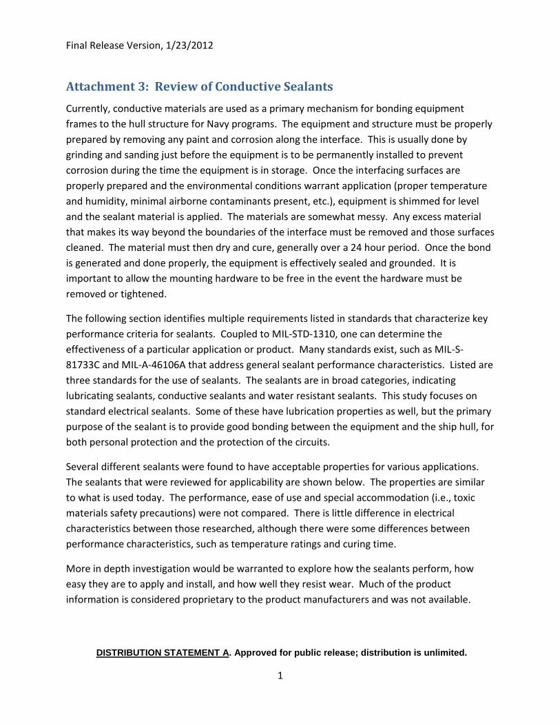
Attachment 3: Review of Conductive Sealants
Currently, conductive materials are used as a primary mechanism for bonding equipment
frames to the hull structure for Navy programs. The equipment and structure must be properly
prepared by removing any paint and corrosion along the interface. This is usually done by
grinding and sanding just before the equipment is to be permanently installed to prevent
corrosion during the time the equipment is in storage. Once the interfacing surfaces are
properly prepared and the environmental conditions warrant application (proper temperature
and humidity, minimal airborne contaminants present, etc.), equipment is shimmed for level
and the sealant material is applied. The materials are somewhat messy. Any excess material
that makes its way beyond the boundaries of the interface must be removed and those surfaces
cleaned. The material must then dry and cure, generally over a 24 hour period. Once the bond
is generated and done properly, the equipment is effectively sealed and grounded. It is
important to allow the mounting hardware to be free in the event the hardware must be
removed or tightened.
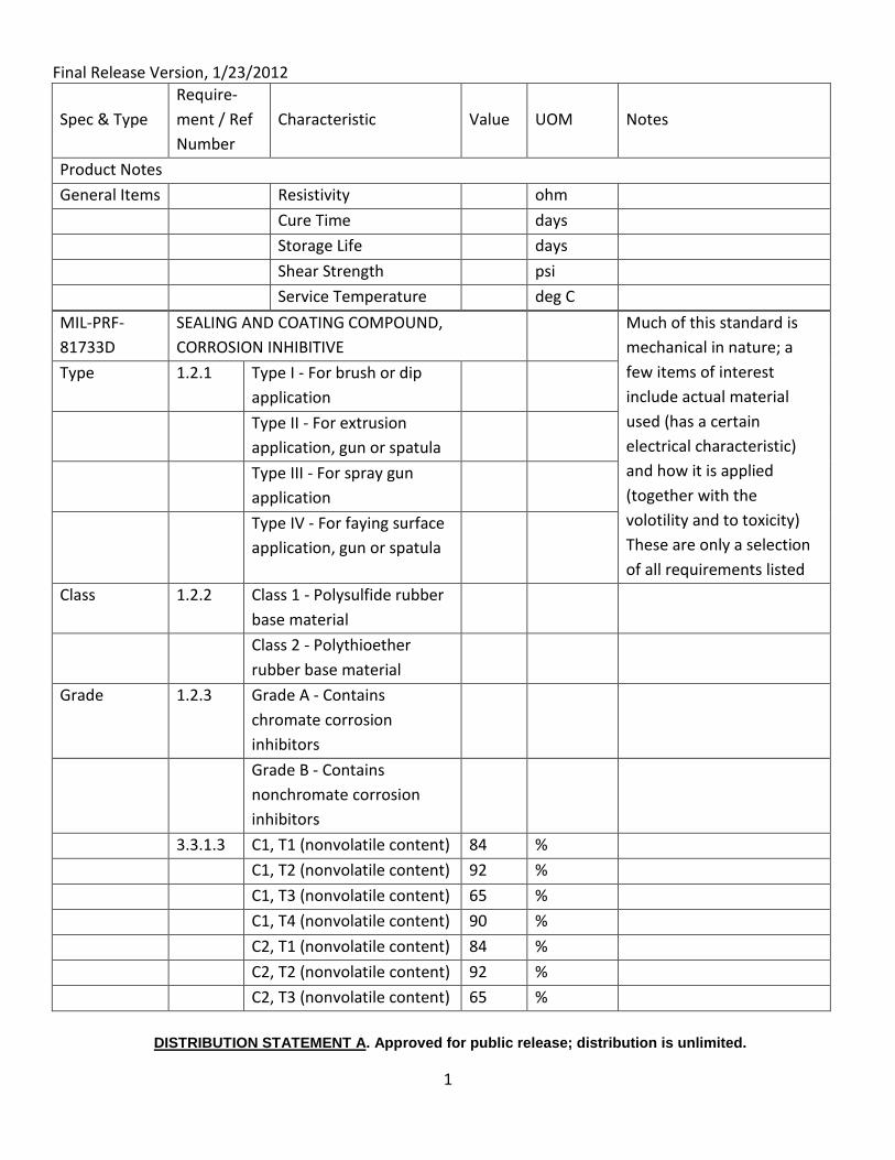
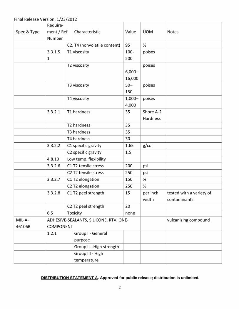
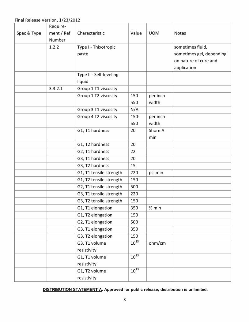
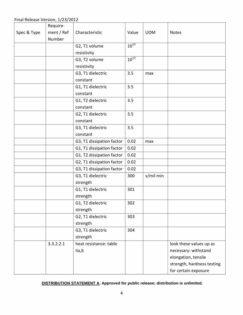
The following section identifies multiple requirements listed in standards that characterize key
performance criteria for sealants. Coupled to MIL-STD-1310, one can determine the
effectiveness of a particular application or product. Many standards exist, such as MIL-S-
81733C and MIL-A-46106A that address general sealant performance characteristics. Listed are
three standards for the use of sealants. The sealants are in broad categories, indicating
lubricating sealants, conductive sealants and water resistant sealants. This study focuses on
standard electrical sealants. Some of these have lubrication properties as well, but the primary
purpose of the sealant is to provide good bonding between the equipment and the ship hull, for
both personal protection and the protection of the circuits.
Several different sealants were found to have acceptable properties for various applications.
The sealants that were reviewed for applicability are shown below. The properties are similar
to what is used today. The performance, ease of use and special accommodation (i.e., toxic
materials safety precautions) were not compared. There is little difference in electrical
characteristics between those researched, although there were some differences between
performance characteristics, such as temperature ratings and curing time.
More in depth investigation would be warranted to explore how the sealants perform, how
easy they are to apply and install, and how well they resist wear. Much of the product
information is considered proprietary to the product manufacturers and was not available.
Final Release Version, 1/23/2012
DISTRIBUTION STATEMENT A. Approved for public release; distribution is unlimited.
1
Spec & Type
Require-
ment / Ref
Number
Characteristic Value UOM Notes
Product Notes
General Items Resistivity ohm
Cure Time days
Storage Life days
Shear Strength psi
Service Temperature deg C
MIL-PRF-
81733D
SEALING AND COATING COMPOUND,
CORROSION INHIBITIVE
Much of this standard is
mechanical in nature; a
few items of interest
include actual material
used (has a certain
electrical characteristic)
and how it is applied
(together with the
volotility and to toxicity)
These are only a selection
of all requirements listed
Type 1.2.1 Type I - For brush or dip
application
Type II - For extrusion
application, gun or spatula
Type III - For spray gun
application
Type IV - For faying surface
application, gun or spatula
Class 1.2.2 Class 1 - Polysulfide rubber
base material
Class 2 - Polythioether
rubber base material
Grade 1.2.3 Grade A - Contains
chromate corrosion
inhibitors
Grade B - Contains
nonchromate corrosion
inhibitors
3.3.1.3 C1, T1 (nonvolatile content) 84 %
C1, T2 (nonvolatile content) 92 %
C1, T3 (nonvolatile content) 65 %
C1, T4 (nonvolatile content) 90 %
C2, T1 (nonvolatile content) 84 %
C2, T2 (nonvolatile content) 92 %
C2, T3 (nonvolatile content) 65 %
Final Release Version, 1/23/2012
DISTRIBUTION STATEMENT A. Approved for public release; distribution is unlimited.
2
Spec & Type
Require-
ment / Ref
Number
Characteristic Value UOM Notes
C2, T4 (nonvolatile content) 95 %
3.3.1.5.
1
T1 viscosity 100-
500
poises
T2 viscosity
6,000–
16,000
poises
T3 viscosity 50–
150
poises
T4 viscosity 1,000–
4,000
poises
3.3.2.1 T1 hardness 35 Shore A-2
Hardness
T2 hardness 35
T3 hardness 35
T4 hardness 30
3.3.2.2 C1 specific gravity 1.65 g/cc
C2 specific gravity 1.5
4.8.10 Low temp. flexibility
3.3.2.6 C1 T2 tensile stress 200 psi
C2 T2 tensile stress 250 psi
3.3.2.7 C1 T2 elongation 150 %
C2 T2 elongation 250 %
3.3.2.8 C1 T2 peel strength 15 per inch
width
tested with a variety of
contaminants
C2 T2 peel strength 20
6.5 Toxicity none
MIL-A-
46106B
ADHESIVE-SEALANTS, SILICONE, RTV, ONE-
COMPONENT
vulcanizing compound
1.2.1 Group I - General
purpose
Group II - High strength
Group III - High
temperature
Final Release Version, 1/23/2012
DISTRIBUTION STATEMENT A. Approved for public release; distribution is unlimited.
3
Spec & Type
Require-
ment / Ref
Number
Characteristic Value UOM Notes
1.2.2 Type I - Thixotropic
paste
sometimes fluid,
sometimes gel, depending
on nature of cure and
application
Type II - Self-leveling
liquid
3.3.2.1 Group 1 T1 viscosity
Group 1 T2 viscosity 150-
550
per inch
width
Group 3 T1 viscosity N/A
Group 4 T2 viscosity 150-
550
per inch
width
G1, T1 hardness 20 Shore A
min
G1, T2 hardness 20
G2, T1 hardness 22
G3, T1 hardness 20
G3, T2 hardness 15
G1, T1 tensile strength 220 psi min
G1, T2 tensile strength 150
G2, T1 tensile strength 500
G3, T1 tensile strength 220
G3, T2 tensile strength 150
G1, T1 elongation 350 % min
G1, T2 elongation 150
G2, T1 elongation 500
G3, T1 elongation 350
G3, T2 elongation 150
G3, T1 volume
resistivity
1013 ohm/cm
G1, T1 volume
resistivity
1013
G1, T2 volume
resistivity
1013
Final Release Version, 1/23/2012
DISTRIBUTION STATEMENT A. Approved for public release; distribution is unlimited.
4
Spec & Type
Require-
ment / Ref
Number
Characteristic Value UOM Notes
G2, T1 volume
resistivity
1013
G3, T2 volume
resistivity
1013
G3, T1 dielectric
constant
3.5 max
G1, T1 dielectric
constant
3.5
G1, T2 dielectric
constant
3.5
G2, T1 dielectric
constant
3.5
G3, T1 dielectric
constant
3.5
G3, T1 dissipation factor 0.02 max
G1, T1 dissipation factor 0.02
G1, T2 dissipation factor 0.02
G2, T1 dissipation factor 0.02
G3, T1 dissipation factor 0.02
G3, T1 dielectric
strength
300 v/mil min
G1, T1 dielectric
strength
301
G1, T2 dielectric
strength
302
G2, T1 dielectric
strength
303
G3, T1 dielectric
strength
304
3.3.2.2.1 heat resistance: table
Iia,b
look these values up as
necessary: withstand
elongation, tensile
strength, hardness testing
for certain exposure
Final Release Version, 1/23/2012
DISTRIBUTION STATEMENT A. Approved for public release; distribution is unlimited.
5
Spec & Type
Require-
ment / Ref
Number
Characteristic Value UOM Notes
3.5 Toxicity none
A-A-59313 Thread Compound, Anti Seize
Compound
The fundamental use for
this type of compound is
for antiseize, not bonding;
however, the properties
augment bonding
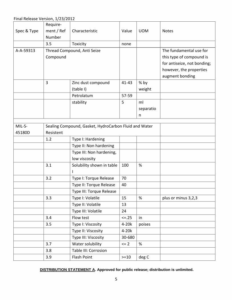
3 Zinc dust compound
(table I)
41-43 % by
weight
Petrolatum 57-59
stability 5 ml
separatio
n
MIL-S-
45180D
Sealing Compound, Gasket, HydroCarbon Fluid and Water
Resistent
1.2 Type I: Hardening
Type II: Non hardening
Type III: Non hardening,
low viscosity
3.1 Solubility shown in table
I
100 %
3.2 Type I: Torque Release 70
Type II: Torque Release 40
Type III: Torque Release
3.3 Type I: Volatile 15 % plus or minus 3,2,3
Type II: Volatile 13
Type III: Volatile 24
3.4 Flow test <=.25 in
3.5 Type I: Viscosity 4-20k poises
Type II: Viscosity 4-20k
Type III: Viscosity 30-680
3.7 Water solubility <= 2 %
3.8 Table III: Corrosion
3.9 Flash Point >=10 deg C
Final Release Version, 1/23/2012
DISTRIBUTION STATEMENT A. Approved for public release; distribution is unlimited.
6
Spec & Type
Require-
ment / Ref
Number
Characteristic Value UOM Notes
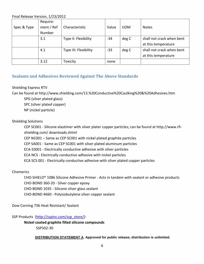
3.1 Type II: Flexibility -34 deg C shall not crack when bent
at this temperature
4.1 Type III: Flexibility -33 deg C shall not crack when bent
at this temperature
3.12 Toxicity none
Sealants and Adhesives Reviewed Against The Above Standards
Shielding Express RTV
Can be found at http://www.shielding.com/13.%20Conductive%20Caulking%20&%20Adhesives.htm
SPG (silver plated glass)
SPC (silver plated copper)
NP (nickel particle)
Shielding Solutions
CEP SC001 - Silicone elastimer with silver plater copper particles; can be found at http://www.rfi-
shielding.com/ downloads.shtml
CEP NC001 – Same as CEP SC001 with nickel plated graphite particles
CEP SA001 - Same as CEP SC001 with silver plated aluminum particles
ECA-SS001 - Electrically conductive adhesive with silver particles
ECA NCS - Electrically conductive adhesive with nickel particles
ECA SCS 001 - Electrically conductive adhesive with silver plated copper particles
Chomerics
CHO-SHIELD® 1086 Silicone Adhesive Primer - Acts in tandem with sealant or adhesive products
CHO-BOND 360-20 - Silver copper epoxy
CHO-BOND 1035 - Silicone silver glass sealant
CHO-BOND 4660 - Polyisobutylene silver copper sealant
Dow Corning 736 Heat Resistant/ Sealant
SSP Products (http://sspinc.com/ssp_store/):
Nickel coated graphite filled silicone compounds
SSP502-30
Final Release Version, 1/23/2012
DISTRIBUTION STATEMENT A. Approved for public release; distribution is unlimited.
7
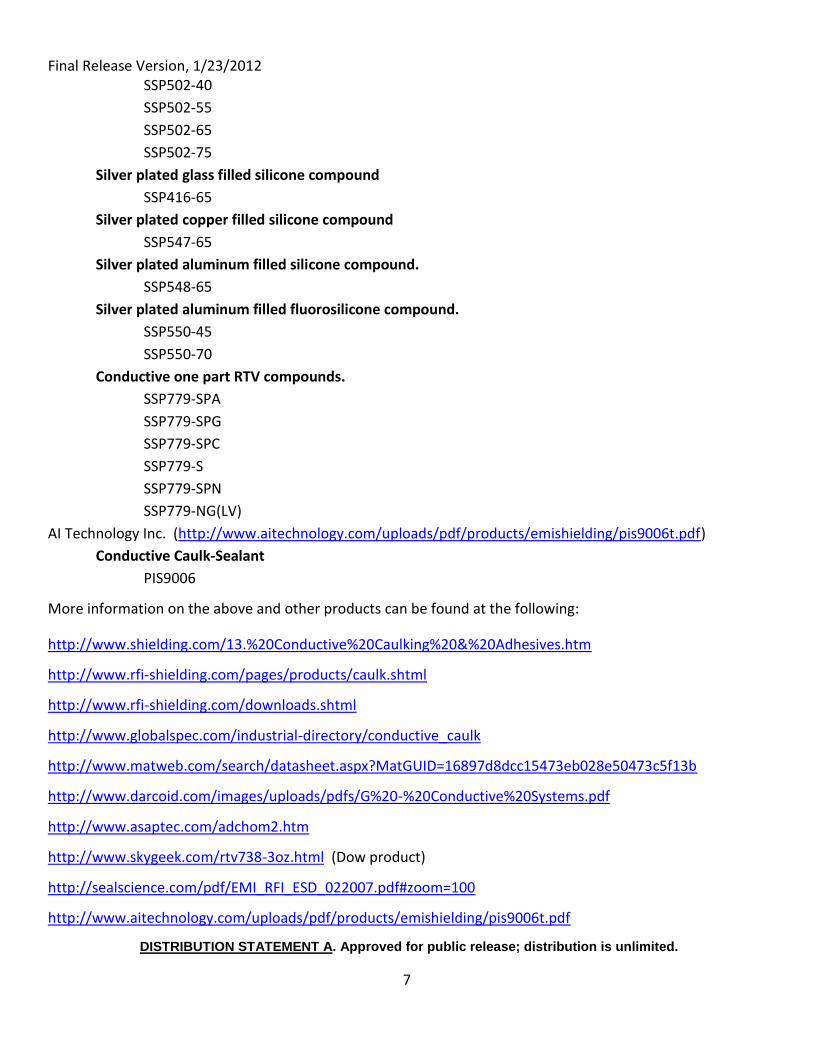
SSP502-40
SSP502-55
SSP502-65
SSP502-75
Silver plated glass filled silicone compound
SSP416-65
Silver plated copper filled silicone compound
SSP547-65
Silver plated aluminum filled silicone compound.
SSP548-65
Silver plated aluminum filled fluorosilicone compound.
SSP550-45
SSP550-70
Conductive one part RTV compounds.
SSP779-SPA
SSP779-SPG
SSP779-SPC
SSP779-S
SSP779-SPN
SSP779-NG(LV)
AI Technology Inc. (http://www.aitechnology.com/uploads/pdf/products/emishielding/pis9006t.pdf)
Conductive Caulk-Sealant
PIS9006
More information on the above and other products can be found at the following:
http://www.shielding.com/13.%20Conductive%20Caulking%20&%20Adhesives.htm
http://www.rfi-shielding.com/pages/products/caulk.shtml
http://www.rfi-shielding.com/downloads.shtml
http://www.globalspec.com/industrial-directory/conductive_caulk
http://www.matweb.com/search/datasheet.aspx?MatGUID=16897d8dcc15473eb028e50473c5f13b
http://www.darcoid.com/images/uploads/pdfs/G%20-%20Conductive%20Systems.pdf
http://www.asaptec.com/adchom2.htm
http://www.skygeek.com/rtv738-3oz.html (Dow product)
http://sealscience.com/pdf/EMI_RFI_ESD_022007.pdf#zoom=100
http://www.aitechnology.com/uploads/pdf/products/emishielding/pis9006t.pdf
Final Release Version, 1/23/2012
DISTRIBUTION STATEMENT A. Approved for public release; distribution is unlimited.
8
http://www.teckniteurope.com/pages/caulk.html
http://www.sspinc.com/products_and_services/EMI_Conductive_Silicone_Compounds
Final Release Version, 1/23/2012
DISTRIBUTION STATEMENT A. Approved for public release; distribution is unlimited.
1
Attachment 4: Proposed Change to MIL STD 1310H
To allow for the use of grounding washers in Class B bonds, after the following quote:
“5.1.3.1 Class B and C bond installation
b. Class B bonding procedure. At least one mounting bolt hole/mounting foot shall be prepared for electrical
safety. All mounting feet/mating surfaces shall be prepared for C5ISR equipment operation and EMI/EMP
mitigation bonding (see 4.2).
(1) Clean mating surfaces (e.g., sand, file, grind, brush, scrape, etc.) down to smooth, bright metal of item
to be mounted. Use care not to gouge deep pits or grooves in the mating surfaces. Clean the contact surface(s) on the
mounting area (ground plane) approximately ¼ inch larger than the mounting foot such that complete bright-metal
contact is achieved when they are mated.”
Insert the following text:
As an alternative to cleaning mating surfaces down to smooth, bright metal, a grounding
washer may be placed between the item to be mounted and its foundation on every mounting
fastener. If grounding washers are used, the following requirements are added:
1. Grounding washers must be 316 grade stainless steel unless another grade of is approved in the ship specification
2. A torque as specified on NavSea Drawing OD32382 Table 1 shall be applied to each mounting fastener.
3. Each new application of fastener size and grounding washer design must be tested under the conditions it will be applied using a micro-ohm meter to verify that the minimum desired ground has been achieved. Once the application is proven to provide a reliable ground, the use of the selected washer and methods can be continued.
4. If tools other than a calibrated torque wrench will be used to apply the specified torque, each worker using alternate tools will undergo annual training to assure they are achieving the desired torque with the tool used for that application.
5. New grounding washers will be applied each time an electrical component is removed and re-installed.
Final Release Version, 1/23/2012
DISTRIBUTION STATEMENT A. Approved for public release; distribution is unlimited.
2
To allow for the use of grounding washers in Class C bonds, after the following quote:
“5.1.3.1 Class B and C bond installation
c. Class C bonding procedure.
(1) Clean (e.g., sand, file, grind, brush, scrape, etc. down to smooth, bright metal) the
surfaces/areas where the bond strap is to be mounted approximately ¼ inch larger than the
bond strap end lug, or boss if installing a Type I bond strap topside. Use care not to gouge deep
pits or grooves in the mating surfaces. The distance between the mounting points shall be as
short as practical to minimize impedance of the strap. Weld bosses in place for Type I bond
strap installations topside. Repaint areas disturbed by welding (see 5.1.3.3.d and figure 11).”
Insert the following text:
As an alternative to cleaning surfaces/areas down to smooth, bright metal where the bond
strap is to be mounted, a grounding washer may be placed between the ground strap and the
surface/areas on the foundation. If grounding washers are used, the following requirements
are added:
1. Grounding washers must be 316 grade stainless steel unless another grade of stainless steel is approved in the ship specification.
2. A torque as specified on NavSea Drawing OD32382 Table 1 shall be applied to each mounting bolt.
3. Each new application of fastener size and grounding washer design must be tested under the conditions it will be applied using a micro-ohm meter to verify that the minimum desired ground has been achieved. Once the application is proven to provide a reliable ground, the use of the selected washer and methods can be continued.
4. If tools other than a calibrated torque wrench will be used to apply the specified torque, each worker using alternate tools will undergo annual training to assure they are achieving the desired torque with the tool used for that application.
5. New grounding washers will be applied each time a grounding strap is removed and re-installed.
Final Release Version, 1/23/2012
DISTRIBUTION STATEMENT A. Approved for public release; distribution is unlimited.
3
In order to allow for the use of a separate grounding conductor in place of a Class B or Class C
bond, insert or modify the following text as indicated:
Modify “4.2 Class B and/or C bonding. Class B and C bonding shall be used only as required for
electrical safety, equipment operation, EMI mitigation, or EMP effects control.”
To read: 4.2 Class B, Class C, and/or Class D bonding. Class B, Class C or Class D bonding shall be
used only as required for electrical safety, equipment operation, EMI mitigation, or EMP effects
control.
Modify “5.1.3 Class B and class C bonding and grounding preparations.
5.1.3.1 Class B and C bond installation. The following procedures shall be used to ensure
effective Class B and Class C bonds.”
To Read: “5.1.3 Class B, Class C, and Class D bonding and grounding preparations.
5.1.3.1 Class B, Class C, and Class D bond installation. The following procedures shall be used to
ensure effective Class B and Class C bonds.”
Add section 5.1.3.1.d as follows:
d. Class D bonding procedure. A separate ground wire / conductor which connects to ship’s
ground plane. The current carrying capacity of the ground wire/conductor shall be equal or
greater than the source conductor. The ground wire may be separate or included inside of the
power supply cable. In either case, it shall have a green colored insulation, if practical.
(1) Clean (e.g., sand, file, grind, brush, scrape, etc. down to smooth, bright metal) the
surface/area where the ground wire / conductor is to be mounted. This surface / area may be
either inside or outside the item being grounded.
(2) Assure the ground wire / conductor is long enough to assure it will not be placed under
strain at any time.
(3) Wipe down the surface / area where the ground wire / conductor is to be mounted with
MIL-C-81302 non-residue type cleaning solvent to ensure they are clean and free of paint chips,
metal filings and other residue.
(4) Apply a thin film of Antiseize zinc dust - Petrolatum (A-A-59313) or equivalent to the cleaned
surface / area and to the threads of all hardware (bolt and/or nut) to be used.
Final Release Version, 1/23/2012
DISTRIBUTION STATEMENT A. Approved for public release; distribution is unlimited.
4
(5) Bolt ground wire / conductor in place and torque bolt to 25 foot-pounds. (5) Seal and
preserve the junction for ground wire / conductors installed topside or in wet spaces.
(6) Seal and preserve the junction for ground wire / conductors installed topside or in wet
spaces. This is only required for junctions that may be exposed to wet conditions and is not
required for connections inside of sealed components.
(a) Apply Permatex Form-A-Gasket #2 (CAGE 01232; NSN 8030-00-849-0071) or
equivalent non-acidic sealing compound around the perimeter of the mating surfaces
and mounting hardware.
(b) Use finger or orangewood stick to contour and mold sealing compound to the edges
of the material around the mating surfaces.
(c) Paint/repaint scraped and brushed areas.”
Note: A connector may be used to provide power and ground to equipment only under the
condition that, should there be more than one power supply, each power supply will include a
ground wire/conductor meeting the above requirements. The ground connection shall be
made prior to any other connection.
Modify “5.1.3.2 Hardware for class B and C bonding. All hardware (e.g., straps, bosses, bolts,
nuts, and washers) used for new or replacement shipboard Class C bonding shall conform to
MIL-DTL-24749 requirements. Unless otherwise specified in an installation control drawing
(ICD) or ship specification, hardware for equipment and metallic items requiring Class B
bonding shall be CRES 316.”
To Read “5.1.3.2 Hardware for class B, class C, and class D bonding. All hardware (e.g., straps,
bosses, bolts, nuts, and washers) used for new or replacement shipboard Class C bonding shall
conform to MIL-DTL-24749 requirements. Unless otherwise specified in an installation control
drawing (ICD) or ship specification, hardware for equipment and metallic items requiring Class B
or Class D bonding shall be CRES 316 unless another grade of is approved in the ship
specification.”
Final Release Version, 1/23/2012
DISTRIBUTION STATEMENT A. Approved for public release; distribution is unlimited.
1
Attachment 5: Commercial Contacts
Each of these electrical equipment manufacturers was contacted at the 2010 International
Workboat Show in New Orleans, LA to discuss the potential for improved bonding and
grounding. Although many more vendors were contacted, these were the contacts who
indicated interest in and/or knowledge of bonding and grounding.
Crawford Electric Derek Robetson, (504) 731-0480
Address: 200 L & A RDMetairie LA 70001 United States www.cescoltd.com
WAGO Corporation
Sunny Goomber, Senior Sales and Applications Engineer for South Central US (832) 886-0146. Tim Williams, Regional Sales Manager, (985) 893-3093. Address: N120 W19129 Freistadt Road, Germantown WI 53022 United States www.wago.us
Key Electronic Solutions
Gary Lyvers, (504) 734 0641 Address: 623 Distributors Row Suite D New Orleans LA 70123 United States www.keyelectronics.net
Summit Electric Supply, Marine Division
Ed Dowey, Marine Division Director, (504) 535 2600 Address: 621 Time Saver Ave. New Orleans LA 70123 United States www.summit.com/marine
Final Release Version, 1/23/2012
DISTRIBUTION STATEMENT A. Approved for public release; distribution is unlimited.
2
Seacoast Electric Company, Inc.
Tom Artinian, Director of Marine, Oil, and Gas (281) 265 0036 Address: 4000 Greenbriar Drive, Suite 150Stafford TX 77477 United States www.seacoastusa.com
PYI, Inc.
Daniel Schalk (425) 355-3669 Address: 12532 Beverly Park Road Lynnwood WA 98020 United States www.pyiinc.com
Newmar
Jim “Kap” Kaplan, Applications and Sales Manager (310) 266-0561 Address: 2911 West Garry Avenue PO Box 1306 Santa Ana CA 92704 United States www.newmarpower.com
Integrated Power & Controls
Keith Hubble, Department Manager, (757) 312-0574 Address: 912 Ventures Way Chesapeake VA 23320 United States www.earl-ind.com
Baton Rouge Marine Electrical Service, Inc.
Dick Brown, President (225) 642-3328 Address: 865 Highway 30Saint Gabriel LA 70776-5014 United States www.brmes.com
Industrial Power Systems, Inc.
Glenn Beaupre (904) 731-8844 ext 15. Address: 3010 Powers Avenue Building 16 Jacksonville FL 32207-8038 United States www.ipsswitchgear.com
Final Release Version, 1/23/2012
DISTRIBUTION STATEMENT A. Approved for public release; distribution is unlimited.
3
L-3 Communications
Aurelie (Possum) Ponvillian, Field Service Engineer. Michael Portier – [email protected] Address: 901 E. Ball RoadAnaheim CA 92805 United States www.L-3com.com/MPS
Eutex International (Sub divisions) Eutex Singapore, Calgary
Wayne Mayo (713) 862-0088 Address: 3409 BrinkmanHouston TX 77018 United States www.eutexinternational.com
Walther Electric, Inc.
Walter Pecherek Jr., National Sales Manager (800) 925-8437, [email protected] Address: 12 World's Fair Drive Unit F Somerset NJ 08873 United States www.waltherelectric.com
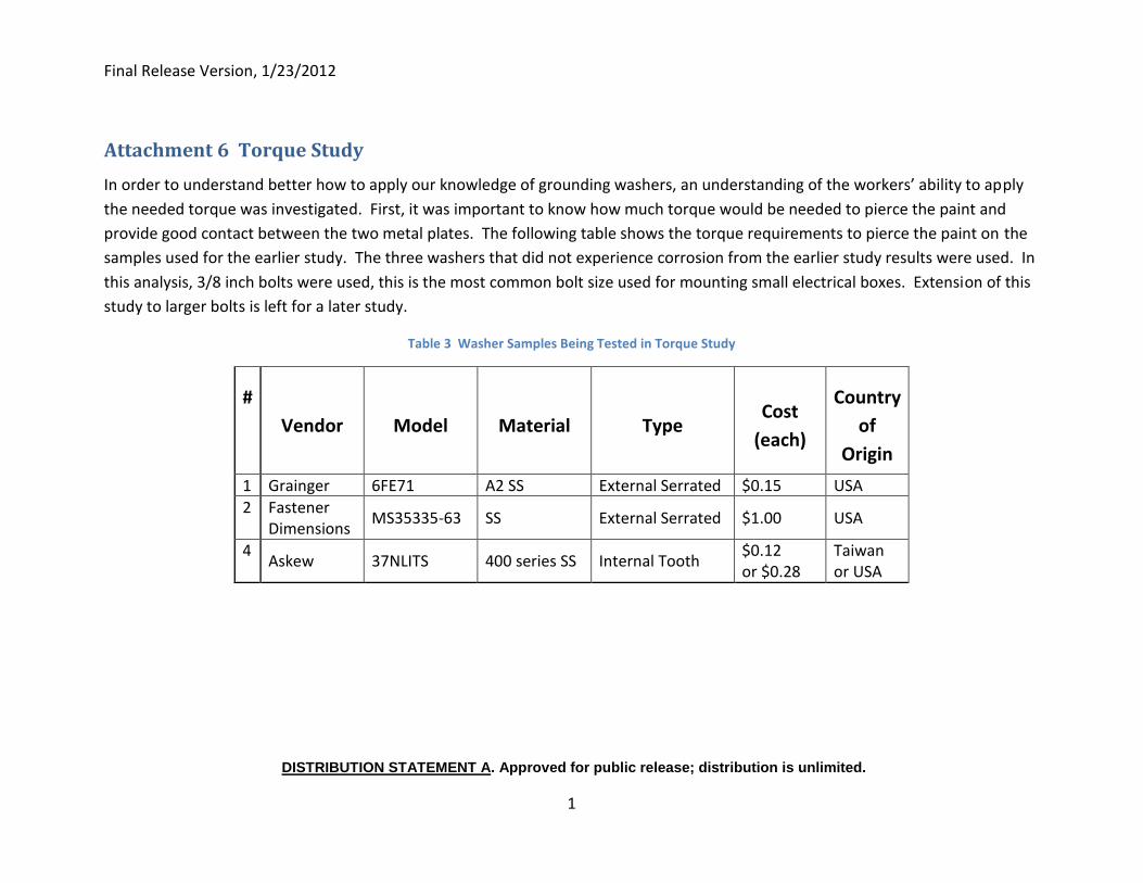
Final Release Version, 1/23/2012
DISTRIBUTION STATEMENT A. Approved for public release; distribution is unlimited.
1
Attachment 6 Torque Study
In order to understand better how to apply our knowledge of grounding washers, an understanding of the workers’ ability to apply
the needed torque was investigated. First, it was important to know how much torque would be needed to pierce the paint and
provide good contact between the two metal plates. The following table shows the torque requirements to pierce the paint on the
samples used for the earlier study. The three washers that did not experience corrosion from the earlier study results were used. In
this analysis, 3/8 inch bolts were used, this is the most common bolt size used for mounting small electrical boxes. Extension of this
study to larger bolts is left for a later study.
Table 3 Washer Samples Being Tested in Torque Study
#
Vendor Model Material Type Cost
(each)
Country
of
Origin
1 Grainger 6FE71 A2 SS External Serrated $0.15 USA
2 Fastener Dimensions
MS35335-63 SS External Serrated $1.00 USA
4 Askew 37NLITS 400 series SS Internal Tooth
$0.12 or $0.28
Taiwan or USA
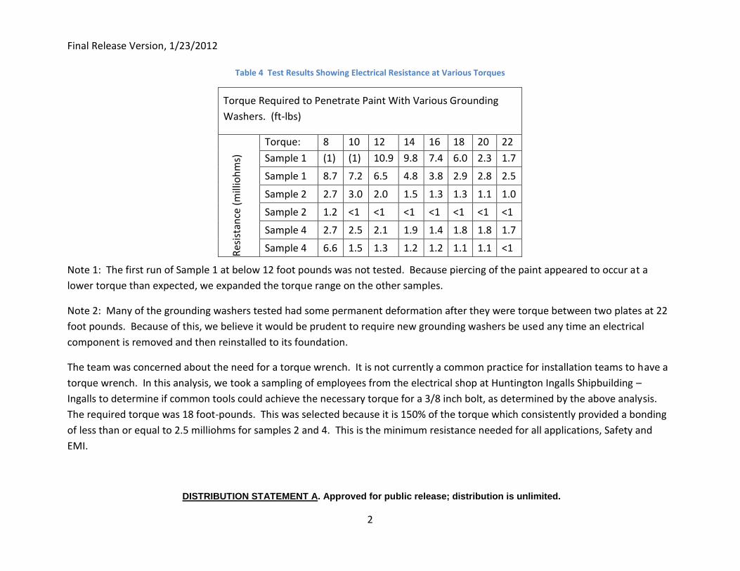
Final Release Version, 1/23/2012
DISTRIBUTION STATEMENT A. Approved for public release; distribution is unlimited.
2
Table 4 Test Results Showing Electrical Resistance at Various Torques
Torque Required to Penetrate Paint With Various Grounding
Washers. (ft-lbs)
Res
ista
nce
(m
illio
hm
s)
Torque: 8 10 12 14 16 18 20 22
Sample 1 (1) (1) 10.9 9.8 7.4 6.0 2.3 1.7
Sample 1 8.7 7.2 6.5 4.8 3.8 2.9 2.8 2.5
Sample 2 2.7 3.0 2.0 1.5 1.3 1.3 1.1 1.0
Sample 2 1.2 <1 <1 <1 <1 <1 <1 <1
Sample 4 2.7 2.5 2.1 1.9 1.4 1.8 1.8 1.7
Sample 4 6.6 1.5 1.3 1.2 1.2 1.1 1.1 <1
Note 1: The first run of Sample 1 at below 12 foot pounds was not tested. Because piercing of the paint appeared to occur at a
lower torque than expected, we expanded the torque range on the other samples.
Note 2: Many of the grounding washers tested had some permanent deformation after they were torque between two plates at 22
foot pounds. Because of this, we believe it would be prudent to require new grounding washers be used any time an electrical
component is removed and then reinstalled to its foundation.
The team was concerned about the need for a torque wrench. It is not currently a common practice for installation teams to have a
torque wrench. In this analysis, we took a sampling of employees from the electrical shop at Huntington Ingalls Shipbuilding –
Ingalls to determine if common tools could achieve the necessary torque for a 3/8 inch bolt, as determined by the above analysis.
The required torque was 18 foot-pounds. This was selected because it is 150% of the torque which consistently provided a bonding
of less than or equal to 2.5 milliohms for samples 2 and 4. This is the minimum resistance needed for all applications, Safety and
EMI.
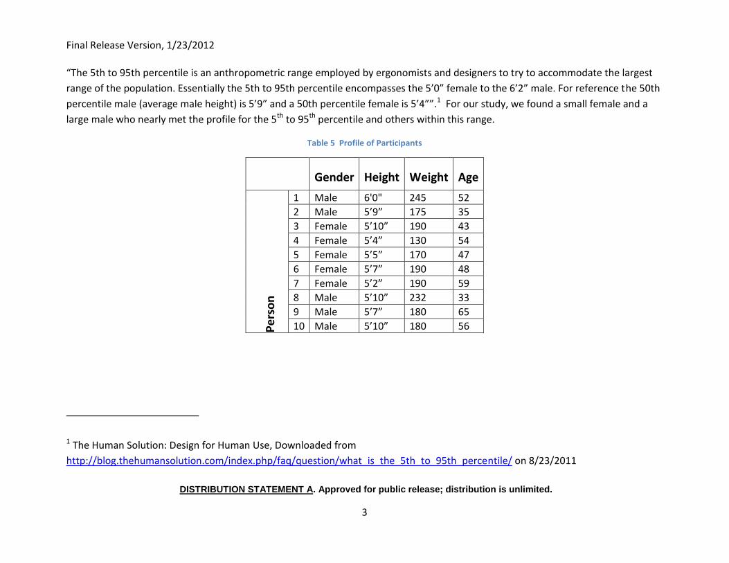
Final Release Version, 1/23/2012
DISTRIBUTION STATEMENT A. Approved for public release; distribution is unlimited.
3
“The 5th to 95th percentile is an anthropometric range employed by ergonomists and designers to try to accommodate the largest
range of the population. Essentially the 5th to 95th percentile encompasses the 5’0” female to the 6’2” male. For reference the 50th
percentile male (average male height) is 5’9” and a 50th percentile female is 5’4””.1 For our study, we found a small female and a
large male who nearly met the profile for the 5th to 95th percentile and others within this range.
Table 5 Profile of Participants
Gender Height Weight Age
Pe
rso
n
1 Male 6'0" 245 52
2 Male 5’9” 175 35
3 Female 5’10” 190 43
4 Female 5’4” 130 54
5 Female 5’5” 170 47
6 Female 5’7” 190 48
7 Female 5’2” 190 59
8 Male 5’10” 232 33
9 Male 5’7” 180 65
10 Male 5’10” 180 56
1 The Human Solution: Design for Human Use, Downloaded from
http://blog.thehumansolution.com/index.php/faq/question/what_is_the_5th_to_95th_percentile/ on 8/23/2011
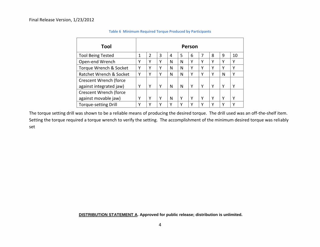
Final Release Version, 1/23/2012
DISTRIBUTION STATEMENT A. Approved for public release; distribution is unlimited.
4
Table 6 Minimum Required Torque Produced by Participants
Tool Person
Tool Being Tested 1 2 3 4 5 6 7 8 9 10
Open-end Wrench Y Y Y N N Y Y Y Y Y
Torque Wrench & Socket Y Y Y N N Y Y Y Y Y
Ratchet Wrench & Socket Y Y Y N N Y Y Y N Y
Crescent Wrench (force against integrated jaw) Y Y Y N N Y Y Y Y Y
Crescent Wrench (force against movable jaw) Y Y Y N Y Y Y Y Y Y
Torque-setting Drill Y Y Y Y Y Y Y Y Y Y
The torque setting drill was shown to be a reliable means of producing the desired torque. The drill used was an off-the-shelf item.
Setting the torque required a torque wrench to verify the setting. The accomplishment of the minimum desired torque was reliably
set
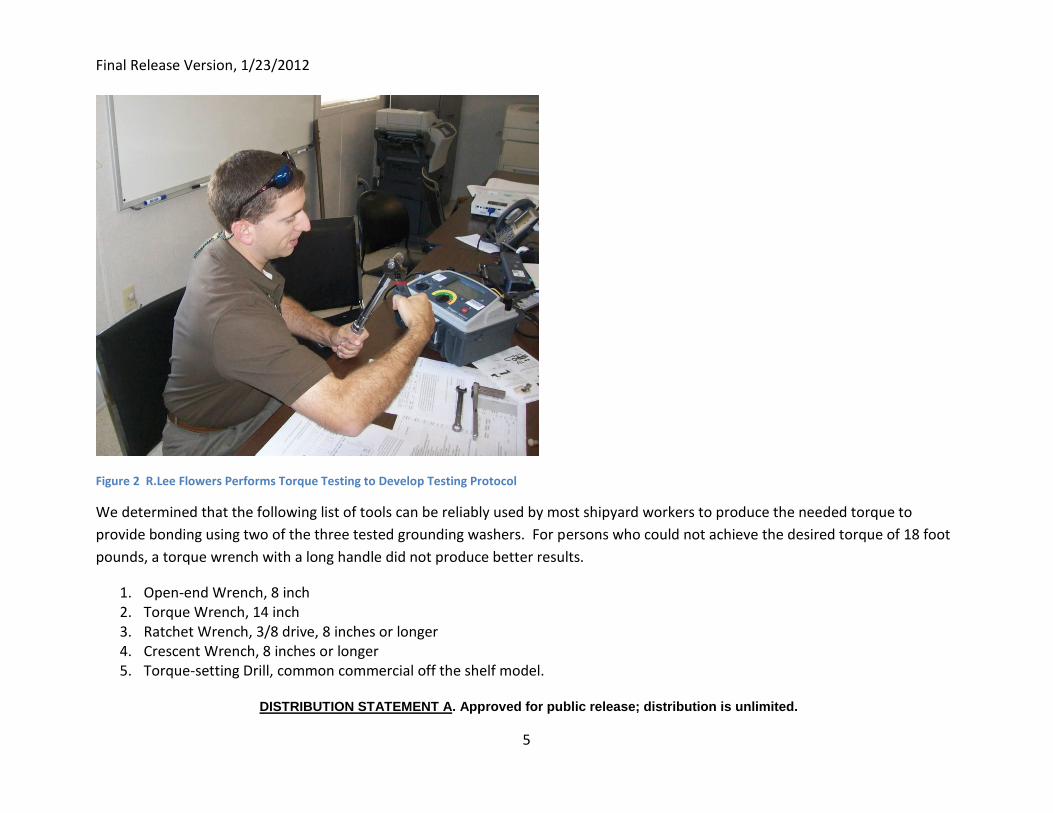
Final Release Version, 1/23/2012
DISTRIBUTION STATEMENT A. Approved for public release; distribution is unlimited.
5
Figure 2 R.Lee Flowers Performs Torque Testing to Develop Testing Protocol
We determined that the following list of tools can be reliably used by most shipyard workers to produce the needed torque to
provide bonding using two of the three tested grounding washers. For persons who could not achieve the desired torque of 18 foot
pounds, a torque wrench with a long handle did not produce better results.
1. Open-end Wrench, 8 inch 2. Torque Wrench, 14 inch 3. Ratchet Wrench, 3/8 drive, 8 inches or longer 4. Crescent Wrench, 8 inches or longer 5. Torque-setting Drill, common commercial off the shelf model.
Final Release Version, 1/23/2012
DISTRIBUTION STATEMENT A. Approved for public release; distribution is unlimited.
6
This finding is important in that requiring a torque wrench would add cost to the use of grounding washers that would off-set some
of the benefits. For bolts larger than 3/8” diameter, the torque requirements will be larger and a torque wrench will probably be
required.
However, 18 foot pounds required a significant effort with all of the tools except the long torque wrench and the torque setting drill.
Should other tools be allowed to install grounding washers, training with refresher training will be required. Each person should be
qualified to assure they can reliably achieve the desired torque.
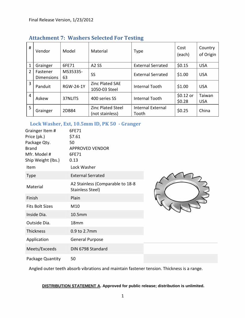
Final Release Version, 1/23/2012
DISTRIBUTION STATEMENT A. Approved for public release; distribution is unlimited.
1
Attachment 7: Washers Selected For Testing
# Vendor Model Material Type
Cost
(each)
Country
of Origin
1 Grainger 6FE71 A2 SS External Serrated $0.15 USA
2 Fastener Dimensions
MS35335-63
SS External Serrated $1.00 USA
3 Panduit RGW-24-1Y
Zinc Plated SAE 1050-03 Steel
Internal Tooth $1.00 USA
4 Askew 37NLITS 400 series SS Internal Tooth
$0.12 or $0.28
Taiwan USA
5 Grainger 2DB84
Zinc Plated Steel (not stainless)
Internal External Tooth
$0.25 China
Lock Washer, Ext, 10.5mm ID, PK 50 - Granger
Grainger Item # 6FE71 Price (pk.) $7.61
Package Qty. 50 Brand APPROVED VENDOR Mfr. Model # 6FE71 Ship Weight (lbs.) 0.13
Item
Lock Washer
Type
External Serrated
Material
A2 Stainless (Comparable to 18-8 Stainless Steel)
Finish
Plain
Fits Bolt Sizes
M10
Inside Dia.
10.5mm
Outside Dia.
18mm
Thickness
0.9 to 2.7mm
Application
General Purpose
Meets/Exceeds
DIN 6798 Standard
Package Quantity
50
Angled outer teeth absorb vibrations and maintain fastener tension. Thickness is a range.
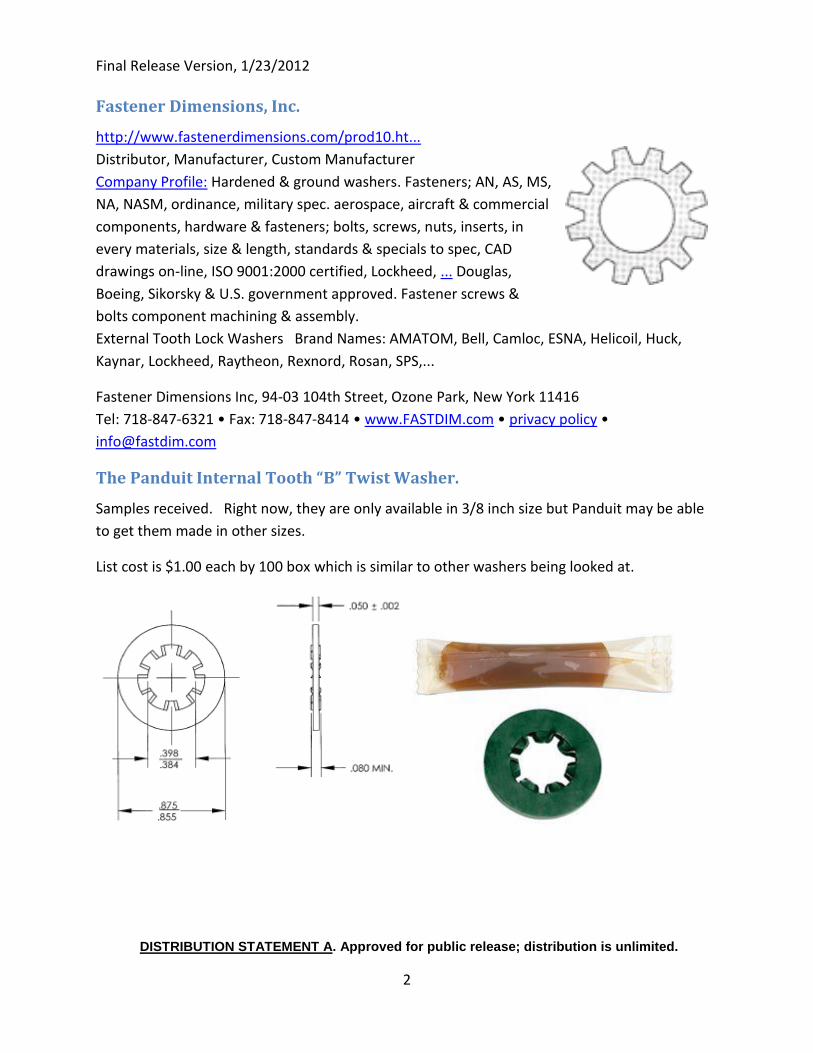
Final Release Version, 1/23/2012
DISTRIBUTION STATEMENT A. Approved for public release; distribution is unlimited.
2
Fastener Dimensions, Inc.
http://www.fastenerdimensions.com/prod10.ht...
Distributor, Manufacturer, Custom Manufacturer
Company Profile: Hardened & ground washers. Fasteners; AN, AS, MS,
NA, NASM, ordinance, military spec. aerospace, aircraft & commercial
components, hardware & fasteners; bolts, screws, nuts, inserts, in
every materials, size & length, standards & specials to spec, CAD
drawings on-line, ISO 9001:2000 certified, Lockheed, ... Douglas,
Boeing, Sikorsky & U.S. government approved. Fastener screws &
bolts component machining & assembly.
External Tooth Lock Washers Brand Names: AMATOM, Bell, Camloc, ESNA, Helicoil, Huck,
Kaynar, Lockheed, Raytheon, Rexnord, Rosan, SPS,...
Fastener Dimensions Inc, 94-03 104th Street, Ozone Park, New York 11416
Tel: 718-847-6321 • Fax: 718-847-8414 • www.FASTDIM.com • privacy policy •
The Panduit Internal Tooth “B” Twist Washer.
Samples received. Right now, they are only available in 3/8 inch size but Panduit may be able
to get them made in other sizes.
List cost is $1.00 each by 100 box which is similar to other washers being looked at.
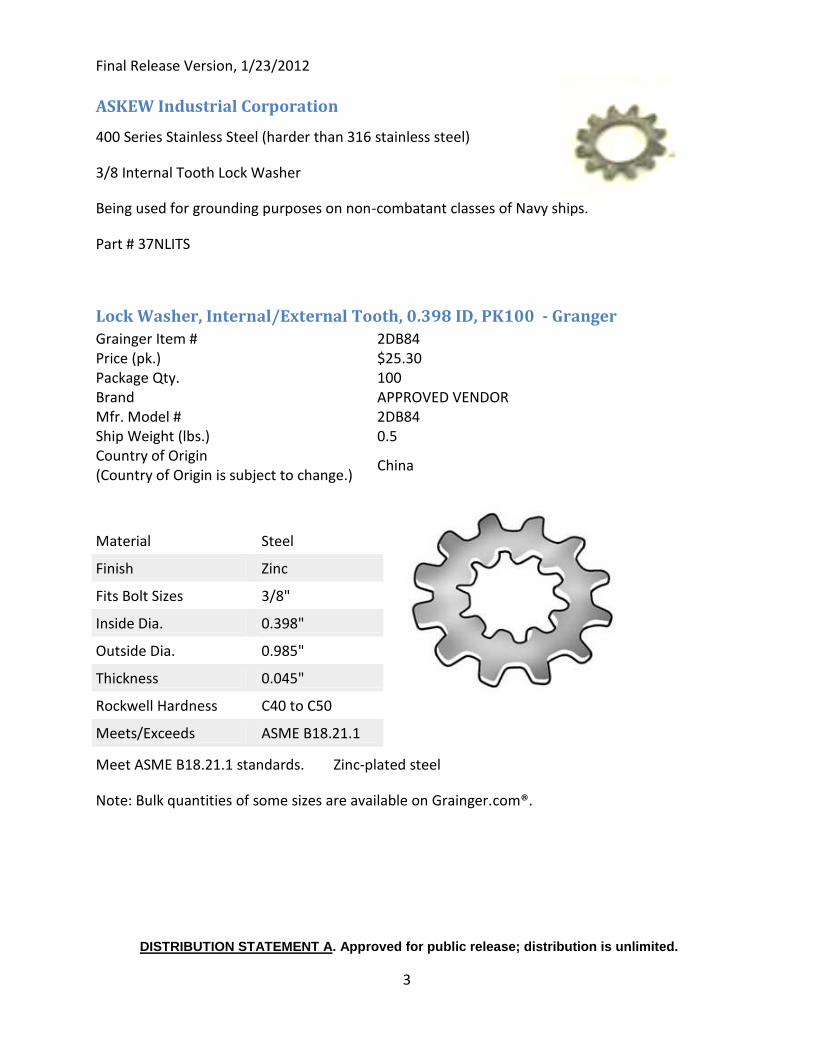
Final Release Version, 1/23/2012
DISTRIBUTION STATEMENT A. Approved for public release; distribution is unlimited.
3
ASKEW Industrial Corporation
400 Series Stainless Steel (harder than 316 stainless steel)
3/8 Internal Tooth Lock Washer
Being used for grounding purposes on non-combatant classes of Navy ships.
Part # 37NLITS
Lock Washer, Internal/External Tooth, 0.398 ID, PK100 - Granger
Grainger Item # 2DB84 Price (pk.) $25.30
Package Qty. 100 Brand APPROVED VENDOR Mfr. Model # 2DB84 Ship Weight (lbs.) 0.5 Country of Origin (Country of Origin is subject to change.)
China
Material
Steel
Finish
Zinc
Fits Bolt Sizes
3/8"
Inside Dia.
0.398"
Outside Dia.
0.985"
Thickness
0.045"
Rockwell Hardness
C40 to C50
Meets/Exceeds
ASME B18.21.1
Meet ASME B18.21.1 standards. Zinc-plated steel
Note: Bulk quantities of some sizes are available on Grainger.com®.
Final Release Version, 1/23/2012
DISTRIBUTION STATEMENT A. Approved for public release; distribution is unlimited.
1
Attachment 8: Preparation of Lab Specimens
Cutting and Drilling of Test Specimens
The test specimens were made of materials commonly available in the shipyard. The steel and
brass bars were 1” x 4”. The steel bar was 3/8” thick and the brass bar was 1/8” thick. Each bar
was drilled with three each 3/8” holes spaced 1” apart.
Blast and Paint Test Specimens
Twenty each small (1” x 4”) steel and brass plates shall be blasted and painted.
Brass Bars:
A light blasting on both faces
Clean with solvent
Paint with 1 coat of 150 green primer
Paint on all surfaces with 1 coat of 111 dove gray. This is the paint schedule for small electrical
cabinets.
Steel Bars:
Blast to remove rust and contaminants
Clean with a solvent to remove blast dust
Paint with 1 coat of 150 green primer
Paint with 1 coat of 156 red paint
This is the same paint schedule used on a machinery foundation in the bilge on a Navy ship.
The Coatings Department at Huntington Ingalls Industries – Ingalls painted the steel bars with
the same paint and thicknesses as they would a steel foundation for an electrical panel. They
painted the brass bars with the same paint and thicknesses as they would a small electrical
panel.
Final Release Version, 1/23/2012
DISTRIBUTION STATEMENT A. Approved for public release; distribution is unlimited.
1
Attachment 9: Test Plan for Bonding and Grounding
Revision 2, 5/25/2011
The 20 each specimens to be tested will be of a common steel bar approximately 4” long x 1” x
3/8” bolted to a brass or brass plate 4” long x 1” x 1/8”. The bolts will be stainless steel and 3/8
diameter. There will be 3 bolts 1½ to 2 inches long. Where the paint is not intact, the stainless
steel bolt may be replaced with a non-conductive nylon bolt.
All stainless bolts will be torque to 22 foot pounds (per NavSea Drawing OD32382 Table 1) and
the nylon bolts will be tightened to hand tight. During assembly, all test items will be coated
with zinc compound at the junction where paint may be removed or pierced. No sealant will be
used on any sample to amplify the effects of the corrosion testing. The 20 specimens will be
numbered and consist of the following items:
1&2 Assembled as per MIL-STD-1310G Class 2 Ground. (Current Practice) The bolting order
will be Bolt Head, Flat Washer, Steel Bar, (removed paint), zinc compound, (removed paint),
Brass Bar, Flat Washer, Lock Washer, Nut.
3&4 Test Item 1, The bolting order will be Bolt Head, Flat Washer, Steel Bar, zinc compound,
Test Item 1, zinc compound, Brass Bar, Flat Washer, Lock Washer, Nut.
5&6 Test Item 2, The bolting order will be Bolt Head, Flat Washer, Steel Bar, zinc compound,
Test Item 2, zinc compound Brass Bar, Flat Washer, Lock Washer, Nut.
7&8 Test Item 3, The bolting order will be Bolt Head, Flat Washer, Steel Bar, zinc compound,
Test Item 3, zinc compound, Brass Bar, Flat Washer, Lock Washer, Nut.
9&10 Test Item 4, The bolting order will be Bolt Head, Flat Washer, Steel Bar, zinc compound,
Test Item 4, zinc compound, Brass Bar, Flat Washer, Lock Washer, Nut.
11&12 Test Item 5, The bolting order will be Bolt Head, Flat Washer, Steel Bar, zinc compound,
Test Item 5, zinc compound, Brass Bar, Flat Washer, Lock Washer, Nut.
The remaining tests are identical to the first ones except that two lock washers are used per
connection instead of one. The lock washers and flat washers are placed as indicated below.
13 Test Item 1, The bolting order will be Bolt Head, Test Item 1, zinc compound, Steel Bar,
Brass Bar, zinc compound, Test Item 1, Nut.
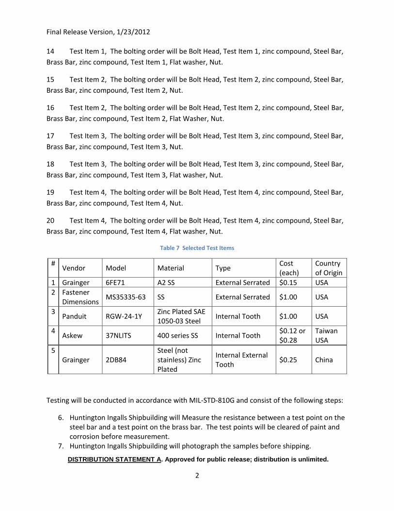
Final Release Version, 1/23/2012
DISTRIBUTION STATEMENT A. Approved for public release; distribution is unlimited.
2
14 Test Item 1, The bolting order will be Bolt Head, Test Item 1, zinc compound, Steel Bar,
Brass Bar, zinc compound, Test Item 1, Flat washer, Nut.
15 Test Item 2, The bolting order will be Bolt Head, Test Item 2, zinc compound, Steel Bar,
Brass Bar, zinc compound, Test Item 2, Nut.
16 Test Item 2, The bolting order will be Bolt Head, Test Item 2, zinc compound, Steel Bar,
Brass Bar, zinc compound, Test Item 2, Flat Washer, Nut.
17 Test Item 3, The bolting order will be Bolt Head, Test Item 3, zinc compound, Steel Bar,
Brass Bar, zinc compound, Test Item 3, Nut.
18 Test Item 3, The bolting order will be Bolt Head, Test Item 3, zinc compound, Steel Bar,
Brass Bar, zinc compound, Test Item 3, Flat washer, Nut.
19 Test Item 4, The bolting order will be Bolt Head, Test Item 4, zinc compound, Steel Bar,
Brass Bar, zinc compound, Test Item 4, Nut.
20 Test Item 4, The bolting order will be Bolt Head, Test Item 4, zinc compound, Steel Bar,
Brass Bar, zinc compound, Test Item 4, Flat washer, Nut.
Table 7 Selected Test Items
# Vendor Model Material Type
Cost (each)
Country of Origin
1 Grainger 6FE71 A2 SS External Serrated $0.15 USA
2 Fastener Dimensions
MS35335-63 SS External Serrated $1.00 USA
3 Panduit RGW-24-1Y
Zinc Plated SAE 1050-03 Steel
Internal Tooth $1.00 USA
4 Askew 37NLITS 400 series SS Internal Tooth
$0.12 or $0.28
Taiwan USA
5 Grainger 2DB84
Steel (not stainless) Zinc Plated
Internal External Tooth
$0.25 China
Testing will be conducted in accordance with MIL-STD-810G and consist of the following steps:
6. Huntington Ingalls Shipbuilding will Measure the resistance between a test point on the steel bar and a test point on the brass bar. The test points will be cleared of paint and corrosion before measurement.
7. Huntington Ingalls Shipbuilding will photograph the samples before shipping.
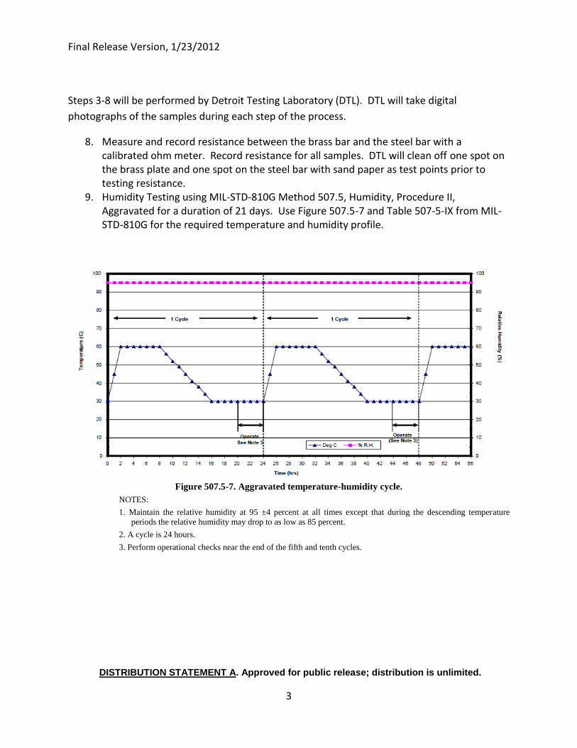
Final Release Version, 1/23/2012
DISTRIBUTION STATEMENT A. Approved for public release; distribution is unlimited.
3
Steps 3-8 will be performed by Detroit Testing Laboratory (DTL). DTL will take digital
photographs of the samples during each step of the process.
8. Measure and record resistance between the brass bar and the steel bar with a calibrated ohm meter. Record resistance for all samples. DTL will clean off one spot on the brass plate and one spot on the steel bar with sand paper as test points prior to testing resistance.
9. Humidity Testing using MIL-STD-810G Method 507.5, Humidity, Procedure II, Aggravated for a duration of 21 days. Use Figure 507.5-7 and Table 507-5-IX from MIL-STD-810G for the required temperature and humidity profile.
Figure 507.5-7. Aggravated temperature-humidity cycle.
NOTES:
1. Maintain the relative humidity at 95 ±4 percent at all times except that during the descending temperature
periods the relative humidity may drop to as low as 85 percent.
2. A cycle is 24 hours.
3. Perform operational checks near the end of the fifth and tenth cycles.
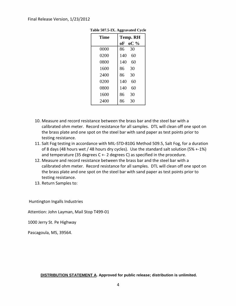
Final Release Version, 1/23/2012
DISTRIBUTION STATEMENT A. Approved for public release; distribution is unlimited.
4
Table 507.5-IX. Aggravated Cycle
Time Temp. RH
oF oC %
0000
0200
0800
1600
2400
0200
0800
1600
2400
86 30
140 60
140 60
86 30
86 30
140 60
140 60
86 30
86 30
10. Measure and record resistance between the brass bar and the steel bar with a calibrated ohm meter. Record resistance for all samples. DTL will clean off one spot on the brass plate and one spot on the steel bar with sand paper as test points prior to testing resistance.
11. Salt Fog testing in accordance with MIL-STD-810G Method 509.5, Salt Fog, for a duration of 8 days (48 hours wet / 48 hours dry cycles). Use the standard salt solution (5% +-1%) and temperature (35 degrees C +- 2 degrees C) as specified in the procedure.
12. Measure and record resistance between the brass bar and the steel bar with a calibrated ohm meter. Record resistance for all samples. DTL will clean off one spot on the brass plate and one spot on the steel bar with sand paper as test points prior to testing resistance.
13. Return Samples to:
Huntington Ingalls Industries
Attention: John Layman, Mail Stop T499-01
1000 Jerry St. Pe Highway
Pascagoula, MS, 39564.

Final Release Version, 1/23/2012
DISTRIBUTION STATEMENT A. Approved for public release; distribution is unlimited.
5
14. Assure Package is insured and has a tracking number. Send test report and digital photos to [email protected]. Include paper copies of test report with samples being returned.
15.
Once the samples are returned to
Huntington Ingalls, we will photograph the
samples and take a resistance check on
them.
At Huntington Ingalls, we will use Megger
model DLR010HD Low Resistance (micro-
ohm) Ohmmeter for resistance checks.
The serial number and calibration
information are recorded below.
The following tables will be used to record
resistance readings:
(This table has been completed with the
resistance readings recorded before the
samples were sent to the testing
laboratory.)
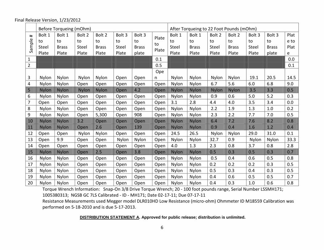
Final Release Version, 1/23/2012
DISTRIBUTION STATEMENT A. Approved for public release; distribution is unlimited.
6
Before Torqueing (mOhm) After Torqueing to 22 Foot Pounds (mOhm)
Sam
ple
# Bolt 1
to Steel Plate
Bolt 1 to Brass Plate
Bolt 2 to Steel Plate
Bolt 2 to Brass Plate
Bolt 3 to Steel Plate
Bolt 3 to Brass plate
Plate to Plate
Bolt 1 to Steel Plate
Bolt 1 to Brass Plate
Bolt 2 to Steel Plate
Bolt 2 to Brass Plate
Bolt 3 to Steel Plate
Bolt 3 to Brass plate
Plate to Plate
1 0.1 0.0
2 0.5 0.1
3 Nylon Nylon Nylon Nylon Open Open Open Nylon Nylon Nylon Nylon 19.1 20.5 14.5
4 Nylon Nylon Open Open Open Open Open Nylon Nylon 6.7 5.6 6.0 6.8 9.0
5 Nylon Nylon Nylon Nylon Open 4.2 Open Nylon Nylon Nylon Nylon 3.5 3.3 0.5
6 Nylon Nylon Open Open Open Open Open Nylon Nylon 0.9 0.6 5.0 5.2 0.3
7 Open Open Open Open Open Open Open 3.1 2.8 4.4 4.0 3.5 3.4 0.0
8 Nylon Nylon Open Open Open Open Open Nylon Nylon 2.2 1.9 1.3 1.0 0.2
9 Nylon Nylon Open 5,300 Open 908 Open Nylon Nylon 2.3 2.2 7.7 7.0 0.5
10 Nylon Nylon 3.2 Open Open Open Open Nylon Nylon 6.4 7.2 7.6 8.2 0.8
11 Nylon Nylon Open 2.6 Open 139 Open Nylon Nylon 0.9 0.4 1.6 1.2 0.4
12 Open Open Nylon Nylon Open Open Open 24.5 26.5 Nylon Nylon 29.0 31.0 0.1
13 Open 9.9 Open Open Nylon Nylon Open Nylon Nylon 32.7 0.9 Nylon Nylon 33.3
14 Open Open Open Open Open Open Open 4.0 1.3 2.3 0.8 3.7 0.8 2.8
15 Nylon Nylon Open 2.5 Open 3.8 Open Nylon Nylon 0.5 0.3 0.5 0.3 0.7
16 Nylon Nylon Open Open Open Open Open Nylon Nylon 0.5 0.4 0.6 0.5 0.8
17 Nylon Nylon Open Open Open Open Open Nylon Nylon 0.2 0.2 0.2 0.3 0.5
18 Nylon Nylon Open Open Open Open Open Nylon Nylon 0.5 0.3 0.4 0.3 0.5
19 Nylon Nylon Open Open Open Open Open Nylon Nylon 0.4 0.6 0.5 0.5 0.7
20 Nylon Nylon Open Open Open Open Open Nylon Nylon 0.4 0.3 1.0 0.6 0.8
Torque Wrench Information: Snap-On 3/8 Drive Torque Wrench; 20 - 100 foot pounds range, Serial Number LSSMH171; 1005380313; NGSB GC 7LS Calibrated - ID - MH171; Date 02-17-11; Due 07-17-11 Resistance Measurements used Megger model DLR010HD Low Resistance (micro-ohm) Ohmmeter ID M18559 Calibration was performed on 5-18-2010 and is due 5-17-2013.
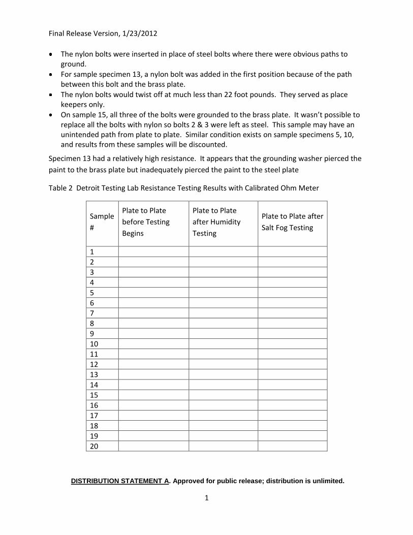
Final Release Version, 1/23/2012
DISTRIBUTION STATEMENT A. Approved for public release; distribution is unlimited.
1
The nylon bolts were inserted in place of steel bolts where there were obvious paths to ground.
For sample specimen 13, a nylon bolt was added in the first position because of the path between this bolt and the brass plate.
The nylon bolts would twist off at much less than 22 foot pounds. They served as place keepers only.
On sample 15, all three of the bolts were grounded to the brass plate. It wasn’t possible to replace all the bolts with nylon so bolts 2 & 3 were left as steel. This sample may have an unintended path from plate to plate. Similar condition exists on sample specimens 5, 10, and results from these samples will be discounted.
Specimen 13 had a relatively high resistance. It appears that the grounding washer pierced the
paint to the brass plate but inadequately pierced the paint to the steel plate
Table 2 Detroit Testing Lab Resistance Testing Results with Calibrated Ohm Meter
Sample
#
Plate to Plate
before Testing
Begins
Plate to Plate
after Humidity
Testing
Plate to Plate after
Salt Fog Testing
1 2 3 4 5 6 7 8 9 10 11 12 13 14 15 16 17 18 19 20
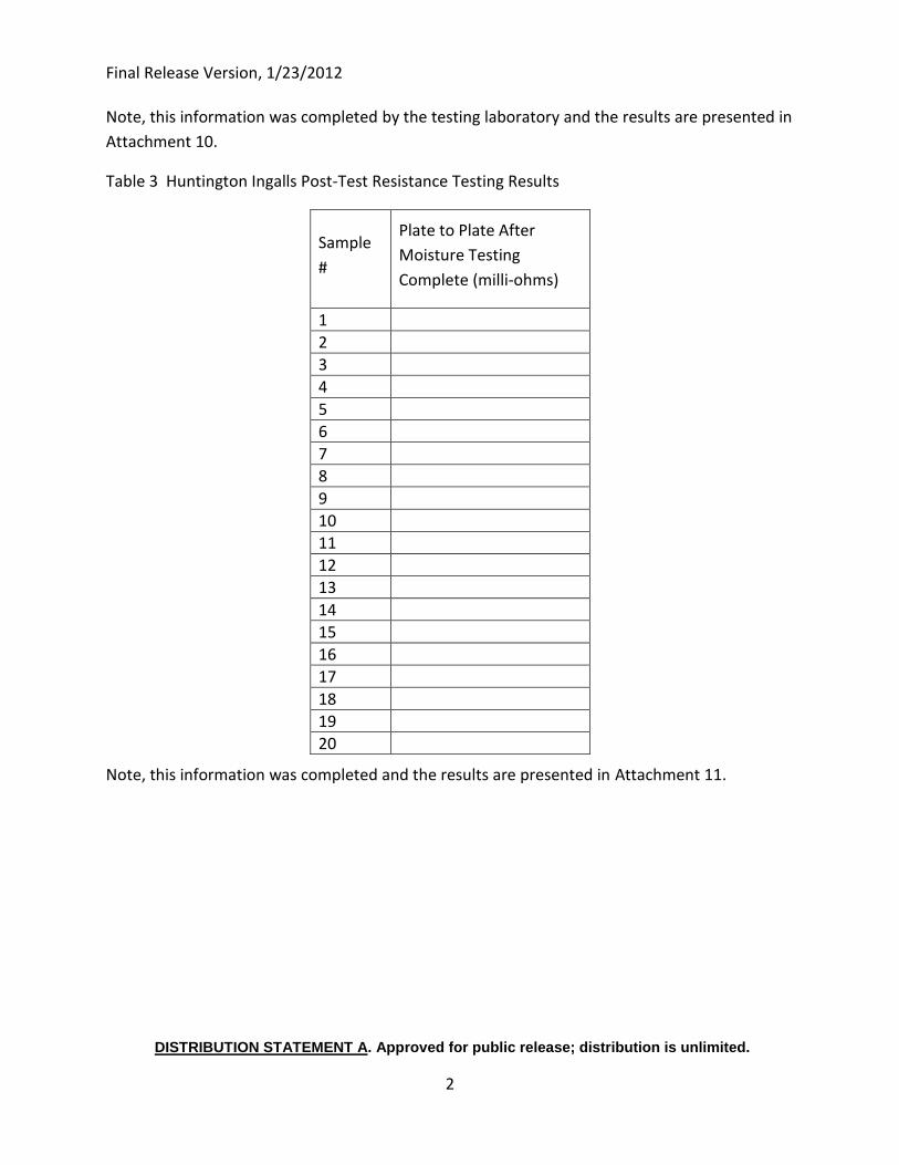
Final Release Version, 1/23/2012
DISTRIBUTION STATEMENT A. Approved for public release; distribution is unlimited.
2
Note, this information was completed by the testing laboratory and the results are presented in
Attachment 10.
Table 3 Huntington Ingalls Post-Test Resistance Testing Results
Sample
#
Plate to Plate After
Moisture Testing
Complete (milli-ohms)
1 2 3 4 5 6 7 8 9 10 11 12 13 14 15 16 17 18 19 20
Note, this information was completed and the results are presented in Attachment 11.
Final Release Version, 1/23/2012
DISTRIBUTION STATEMENT A. Approved for public release; distribution is unlimited.
1
Attachment 10: Vendor Lab Report Findings (excerpts only)
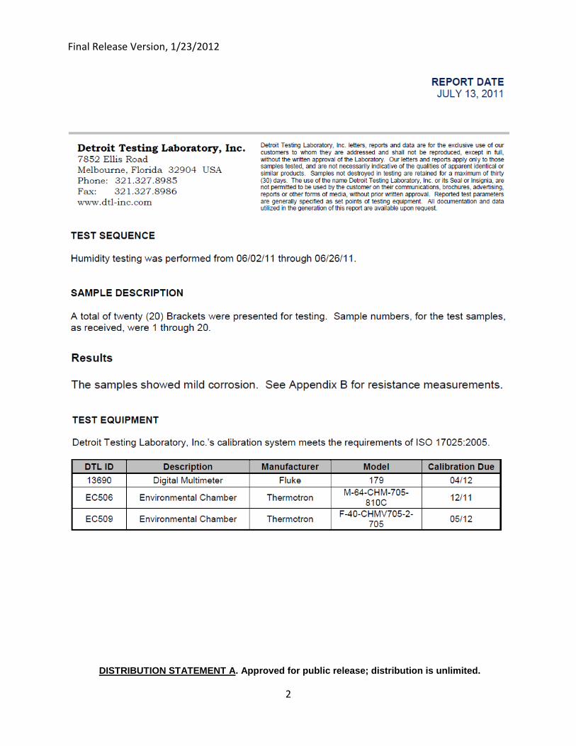
Final Release Version, 1/23/2012
DISTRIBUTION STATEMENT A. Approved for public release; distribution is unlimited.
2
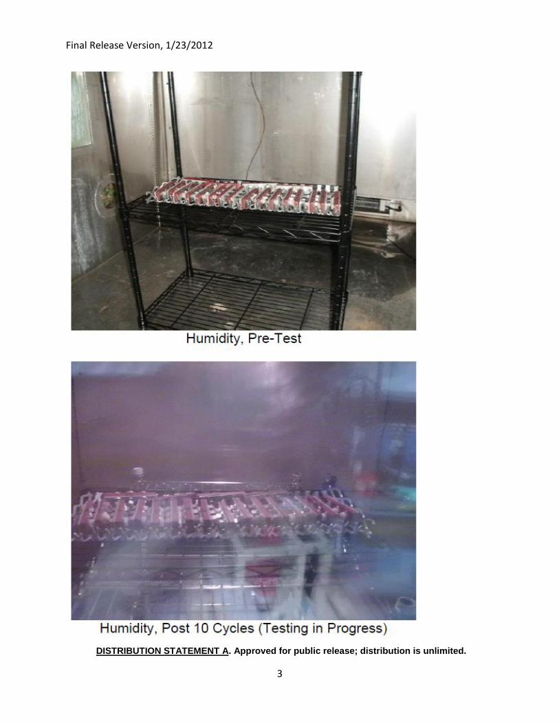
Final Release Version, 1/23/2012
DISTRIBUTION STATEMENT A. Approved for public release; distribution is unlimited.
3
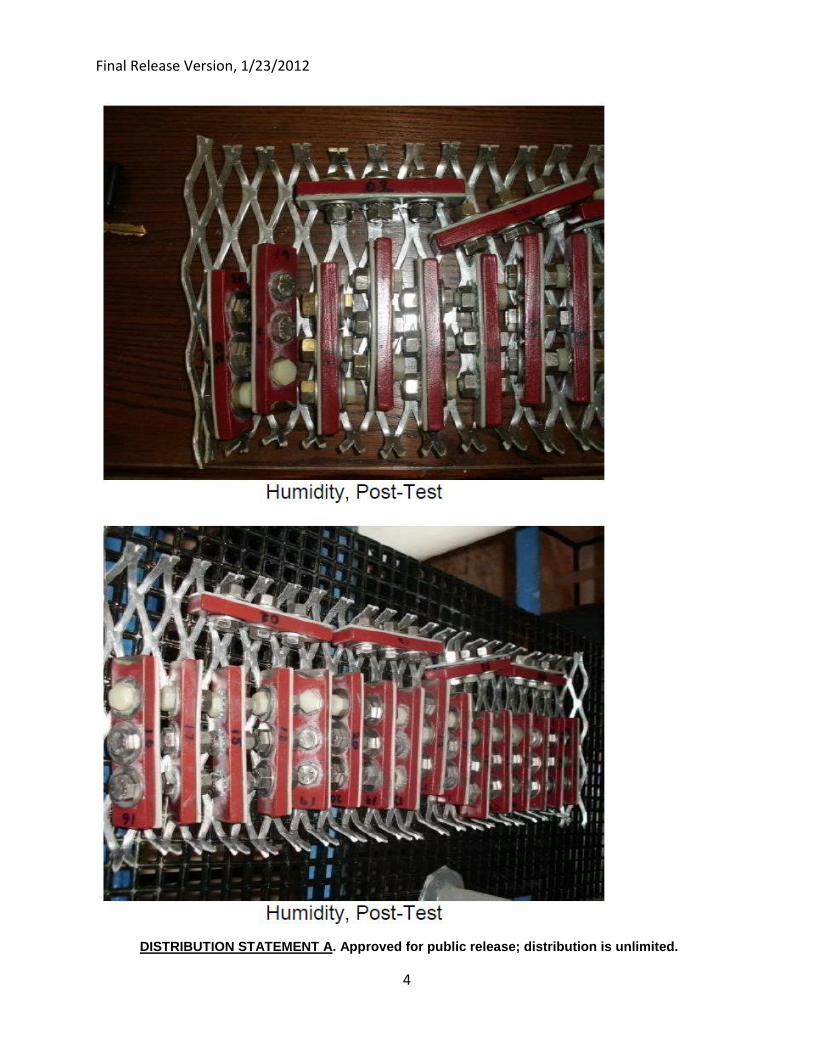
Final Release Version, 1/23/2012
DISTRIBUTION STATEMENT A. Approved for public release; distribution is unlimited.
4
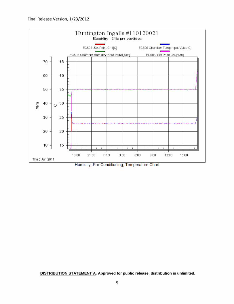
Final Release Version, 1/23/2012
DISTRIBUTION STATEMENT A. Approved for public release; distribution is unlimited.
5
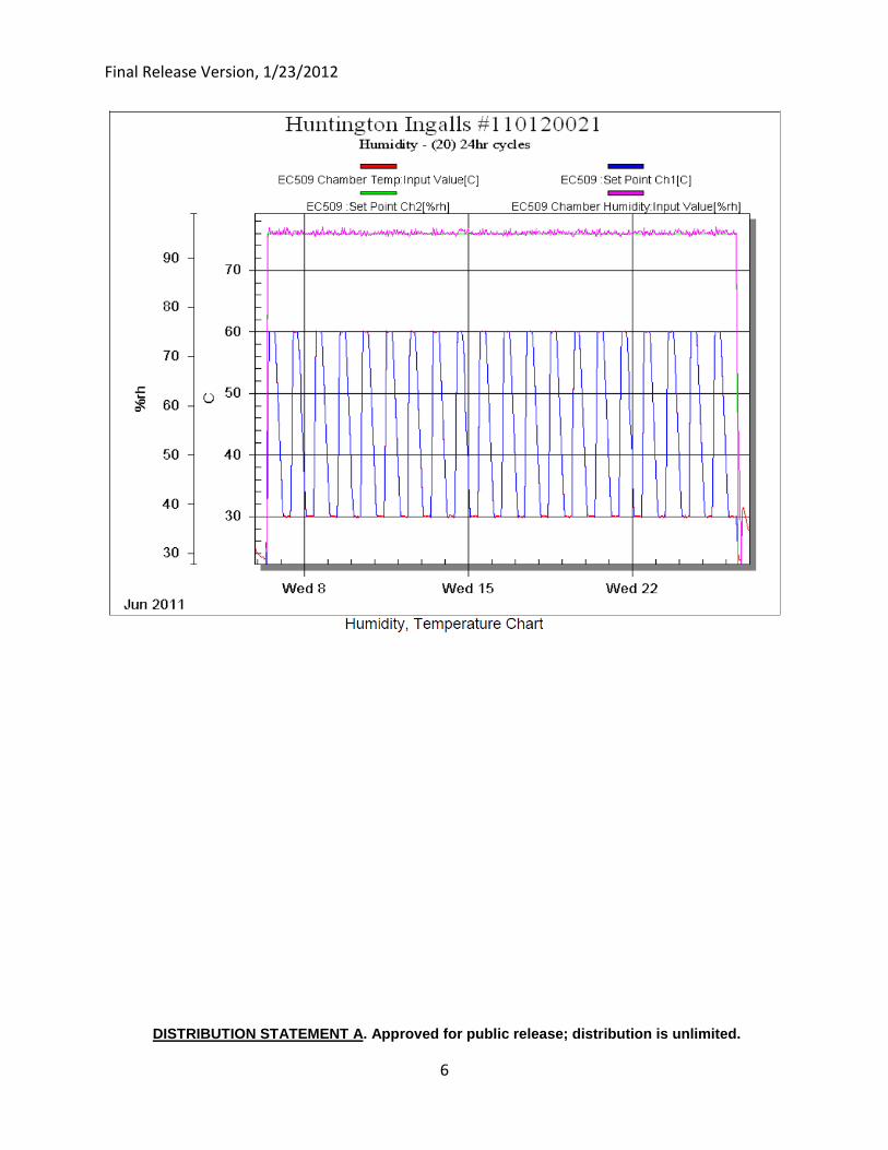
Final Release Version, 1/23/2012
DISTRIBUTION STATEMENT A. Approved for public release; distribution is unlimited.
6
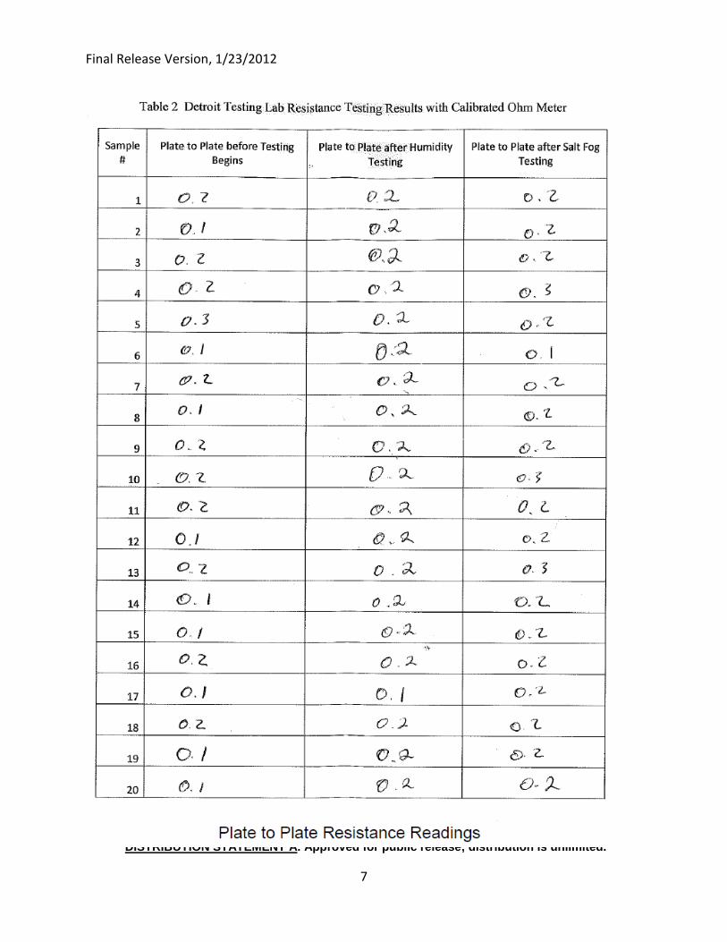
Final Release Version, 1/23/2012
DISTRIBUTION STATEMENT A. Approved for public release; distribution is unlimited.
7
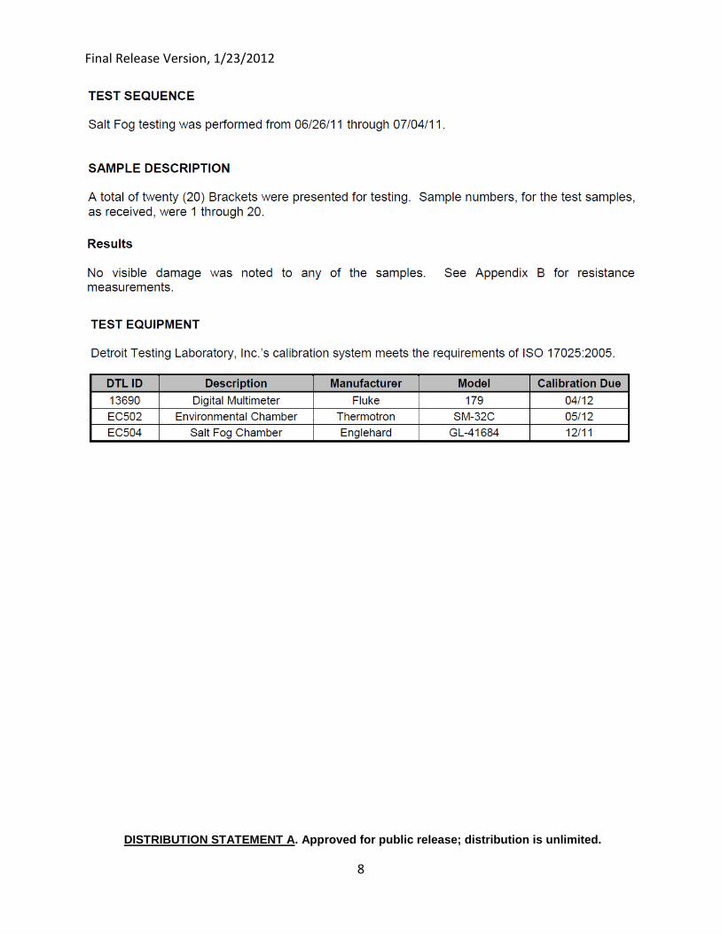
Final Release Version, 1/23/2012
DISTRIBUTION STATEMENT A. Approved for public release; distribution is unlimited.
8
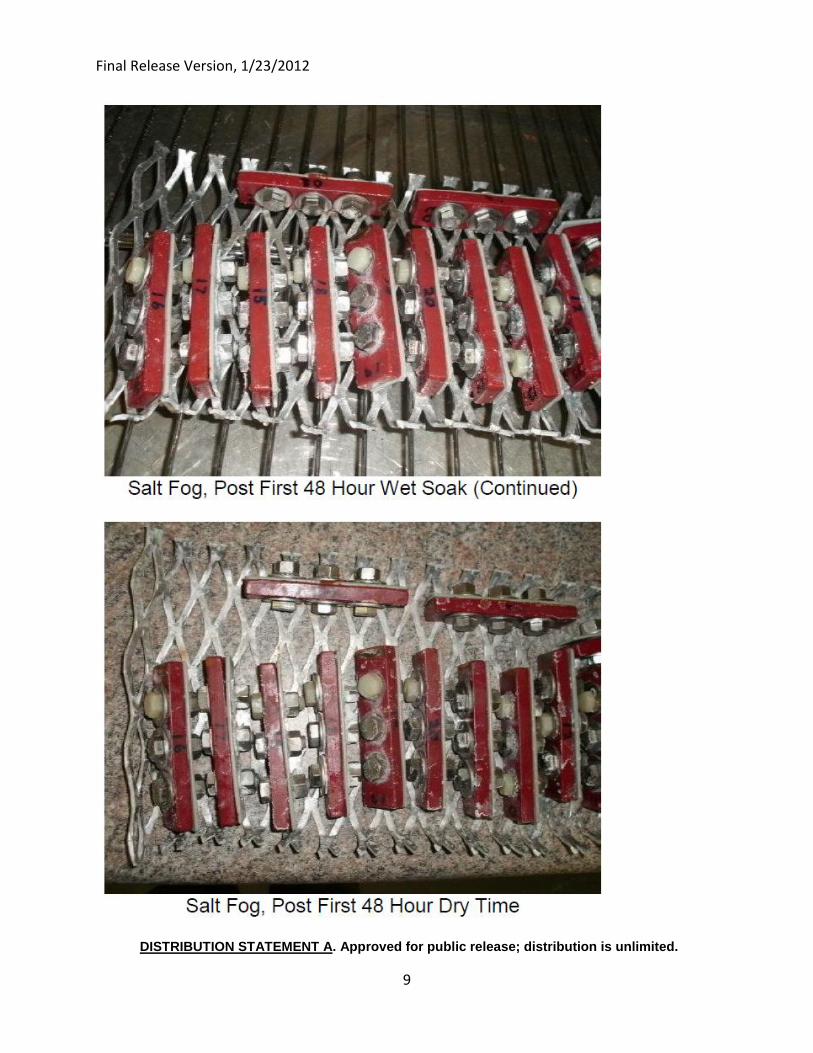
Final Release Version, 1/23/2012
DISTRIBUTION STATEMENT A. Approved for public release; distribution is unlimited.
9
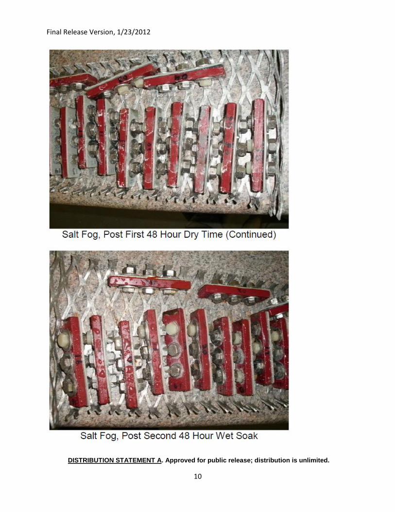
Final Release Version, 1/23/2012
DISTRIBUTION STATEMENT A. Approved for public release; distribution is unlimited.
10
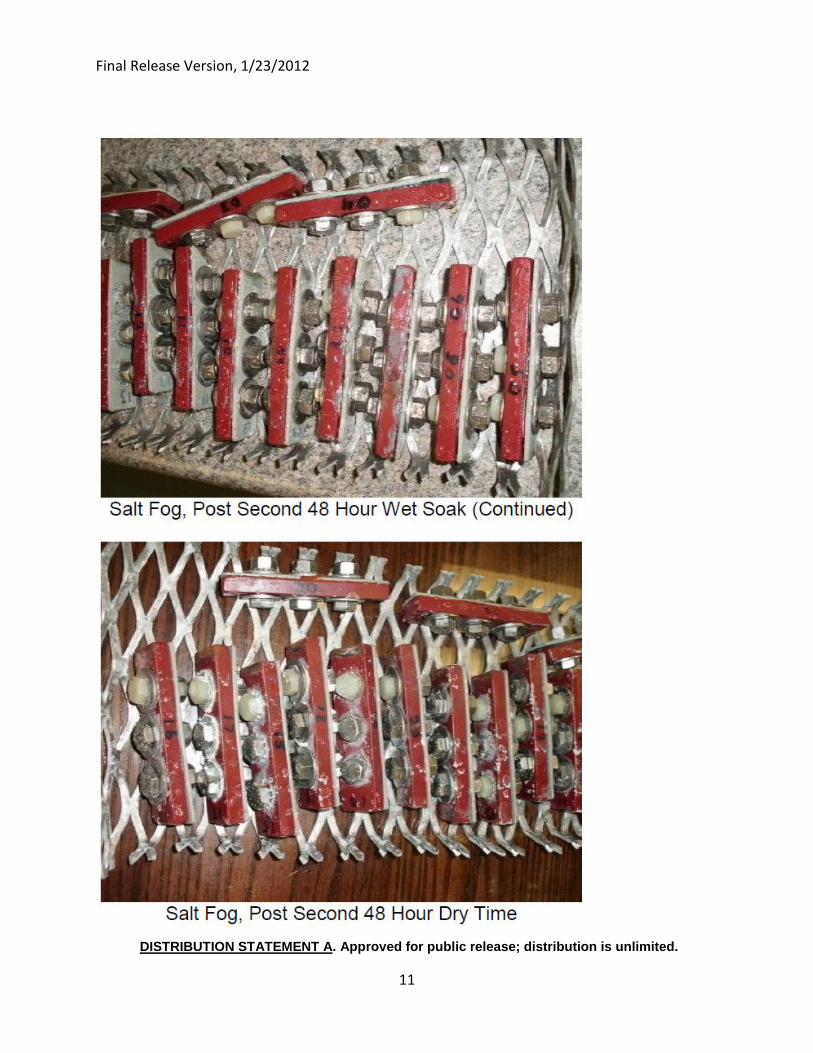
Final Release Version, 1/23/2012
DISTRIBUTION STATEMENT A. Approved for public release; distribution is unlimited.
11
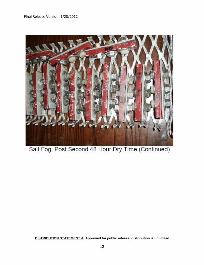
Final Release Version, 1/23/2012
DISTRIBUTION STATEMENT A. Approved for public release; distribution is unlimited.
12
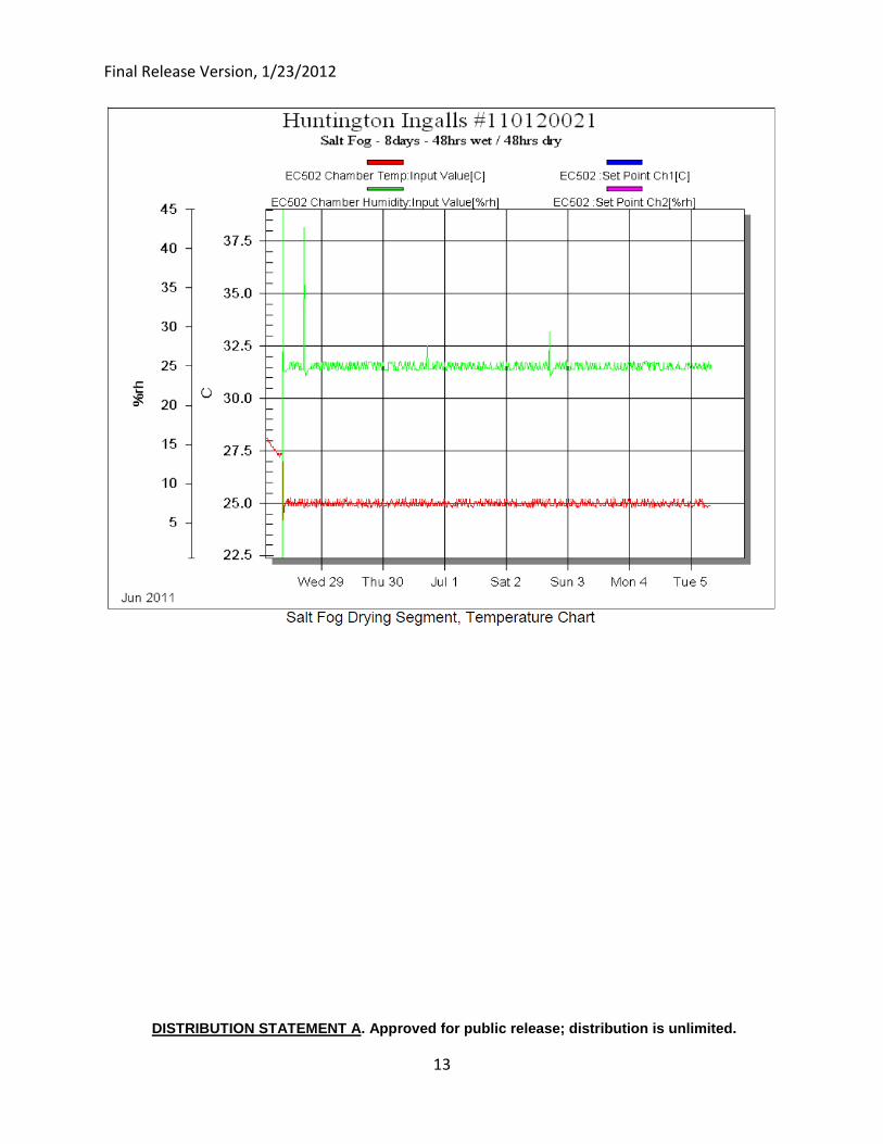
Final Release Version, 1/23/2012
DISTRIBUTION STATEMENT A. Approved for public release; distribution is unlimited.
13
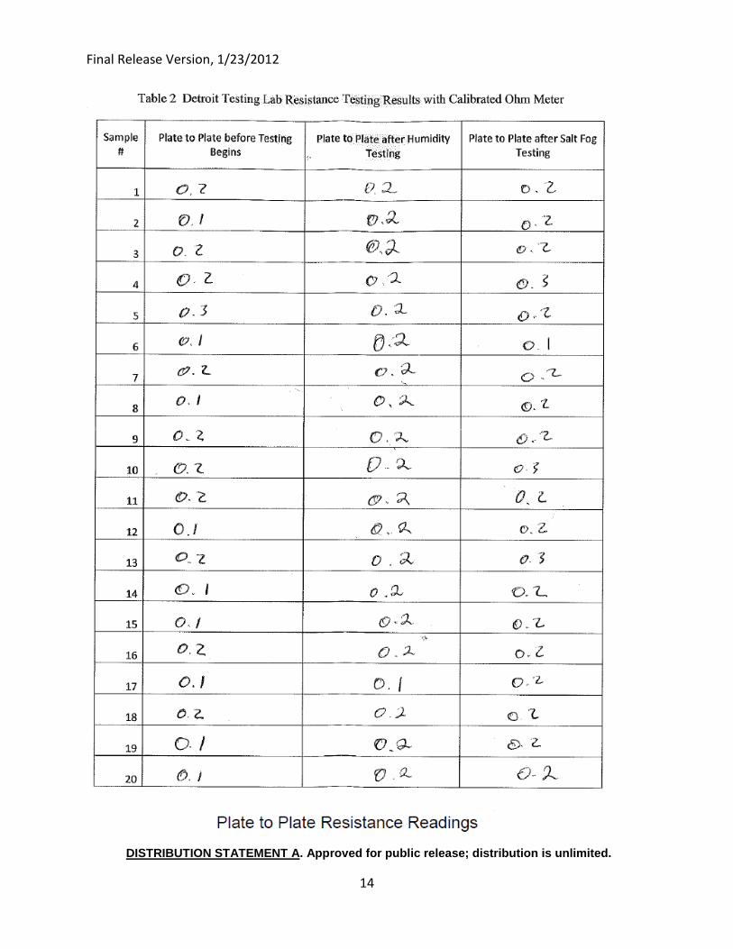
Final Release Version, 1/23/2012
DISTRIBUTION STATEMENT A. Approved for public release; distribution is unlimited.
14
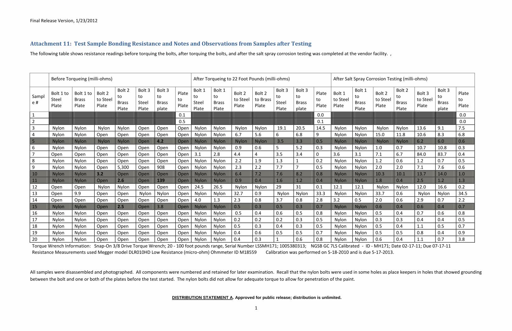
Final Release Version, 1/23/2012
DISTRIBUTION STATEMENT A. Approved for public release; distribution is unlimited.
1
Attachment 11: Test Sample Bonding Resistance and Notes and Observations from Samples after Testing
The following table shows resistance readings before torquing the bolts, after torquing the bolts, and after the salt spray corrosion testing was completed at the vendor facility. ,
Before Torqueing (milli-ohms) After Torqueing to 22 Foot Pounds (milli-ohms) After Salt Spray Corrosion Testing (milli-ohms)
Sample #
Bolt 1 to Steel Plate
Bolt 1 to Brass Plate
Bolt 2 to Steel Plate
Bolt 2 to Brass Plate
Bolt 3 to Steel Plate
Bolt 3 to Brass plate
Plate to Plate
Bolt 1 to Steel Plate
Bolt 1 to Brass Plate
Bolt 2 to Steel Plate
Bolt 2 to Brass Plate
Bolt 3 to Steel Plate
Bolt 3 to Brass plate
Plate to Plate
Bolt 1 to Steel Plate
Bolt 1 to Brass Plate
Bolt 2 to Steel Plate
Bolt 2 to Brass Plate
Bolt 3 to Steel Plate
Bolt 3 to Brass plate
Plate to Plate
1 0.1 0.0 0.0
2 0.5 0.1 0.0
3 Nylon Nylon Nylon Nylon Open Open Open Nylon Nylon Nylon Nylon 19.1 20.5 14.5 Nylon Nylon Nylon Nylon 13.6 9.1 7.5
4 Nylon Nylon Open Open Open Open Open Nylon Nylon 6.7 5.6 6 6.8 9 Nylon Nylon 15.0 11.8 10.6 8.3 6.8
5 Nylon Nylon Nylon Nylon Open 4.2 Open Nylon Nylon Nylon Nylon 3.5 3.3 0.5 Nylon Nylon Nylon Nylon 6.2 6.0 0.6
6 Nylon Nylon Open Open Open Open Open Nylon Nylon 0.9 0.6 5 5.2 0.3 Nylon Nylon 1.0 0.7 10.7 10.8 0.3
7 Open Open Open Open Open Open Open 3.1 2.8 4.4 4 3.5 3.4 0 3.6 3.1 7.1 6.7 84.0 83.7 0.4
8 Nylon Nylon Open Open Open Open Open Nylon Nylon 2.2 1.9 1.3 1 0.2 Nylon Nylon 1.2 0.6 1.2 0.7 0.5
9 Nylon Nylon Open 5,300 Open 908 Open Nylon Nylon 2.3 2.2 7.7 7 0.5 Nylon Nylon 2.0 2.0 7.1 7.6 0.6
10 Nylon Nylon 3.2 Open Open Open Open Nylon Nylon 6.4 7.2 7.6 8.2 0.8 Nylon Nylon 10.3 10.1 13.7 14.0 1.0
11 Nylon Nylon Open 2.6 Open 139 Open Nylon Nylon 0.9 0.4 1.6 1.2 0.4 Nylon Nylon 1.8 0.4 2.5 1.2 1.3
12 Open Open Nylon Nylon Open Open Open 24.5 26.5 Nylon Nylon 29 31 0.1 12.1 12.1 Nylon Nylon 12.0 16.6 0.2
13 Open 9.9 Open Open Nylon Nylon Open Nylon Nylon 32.7 0.9 Nylon Nylon 33.3 Nylon Nylon 33.7 0.6 Nylon Nylon 34.5
14 Open Open Open Open Open Open Open 4.0 1.3 2.3 0.8 3.7 0.8 2.8 3.2 0.5 2.0 0.6 2.9 0.7 2.2
15 Nylon Nylon Open 2.5 Open 3.8 Open Nylon Nylon 0.5 0.3 0.5 0.3 0.7 Nylon Nylon 0.6 0.4 0.6 0.4 0.7
16 Nylon Nylon Open Open Open Open Open Nylon Nylon 0.5 0.4 0.6 0.5 0.8 Nylon Nylon 0.5 0.4 0.7 0.6 0.8
17 Nylon Nylon Open Open Open Open Open Nylon Nylon 0.2 0.2 0.2 0.3 0.5 Nylon Nylon 0.3 0.3 0.4 0.4 0.5
18 Nylon Nylon Open Open Open Open Open Nylon Nylon 0.5 0.3 0.4 0.3 0.5 Nylon Nylon 0.5 0.4 1.1 0.5 0.7
19 Nylon Nylon Open Open Open Open Open Nylon Nylon 0.4 0.6 0.5 0.5 0.7 Nylon Nylon 0.5 0.5 0.8 0.4 0.9
20 Nylon Nylon Open Open Open Open Open Nylon Nylon 0.4 0.3 1 0.6 0.8 Nylon Nylon 0.6 0.4 1.1 0.7 3.8
Torque Wrench Information: Snap-On 3/8 Drive Torque Wrench; 20 - 100 foot pounds range, Serial Number LSSMH171; 1005380313; NGSB GC 7LS Calibrated - ID - MH171; Date 02-17-11; Due 07-17-11
Resistance Measurements used Megger model DLR010HD Low Resistance (micro-ohm) Ohmmeter ID M18559 Calibration was performed on 5-18-2010 and is due 5-17-2013.
All samples were disassembled and photographed. All components were numbered and retained for later examination. Recall that the nylon bolts were used in some holes as place keepers in holes that showed grounding
between the bolt and one or both of the plates before the test started. The nylon bolts did not allow for adequate torque to allow for penetration of the paint.
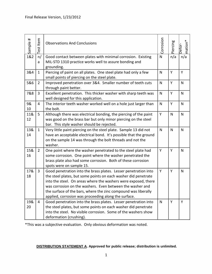
Final Release Version, 1/23/2012
DISTRIBUTION STATEMENT A. Approved for public release; distribution is unlimited.
1
Sa
mp
le #
Test
Item
Observations And Conclusions
Co
rro
sio
n
Pie
rcin
g
Def
or-
mat
ion
*
1&2 n/a
Good contact between plates with minimal corrosion. Existing MIL-STD 1310 practice works well to assure bonding and grounding.
N n/a n/a
3&4 1 Piercing of paint on all plates. One steel plate had only a few small points of piercing on the steel plate.
N Y Y
5&6 2 Improved penetration over 3&4. Smaller number of teeth cuts through paint better.
N Y N
7&8 3 Excellent penetration. This thicker washer with sharp teeth was well designed for this application.
N Y N
9& 10
4 The interior teeth washer worked well on a hole just larger than the bolt.
N Y N
11&12
5 Although there was electrical bonding, the piercing of the paint was good on the brass bar but only minor piercing on the steel bar. This style washer should be rejected.
Y N N
13& 14
1 Very little paint piercing on the steel plate. Sample 13 did not have an acceptable electrical bond. It’s possible that the ground on the sample 14 was through the bolt threads and not the washer.
N N N
15&16
2 One point where the washer penetrated to the steel plate had some corrosion. One point where the washer penetrated the brass plate also had some corrosion. Both of these corrosion spots were on sample 15.
Y Y N
17&18
3 Good penetration into the brass plates. Lesser penetration into the steel plates, but some points on each washer did penetrate into the steel. On areas where the washers were exposed, there was corrosion on the washers. Even between the washer and the surface of the bars, where the zinc compound was liberally applied, corrosion was proceeding along the surface.
Y Y N
19&20
4 Good penetration into the brass plates. Lesser penetration into the steel plates, but some points on each washer did penetrate into the steel. No visible corrosion. Some of the washers show deformation (crushing).
N Y Y
*This was a subjective evaluation. Only obvious deformation was noted.
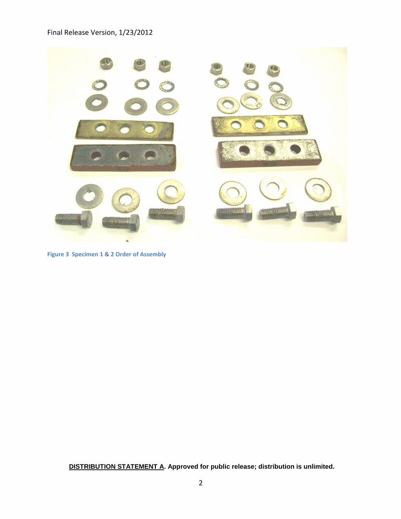
Final Release Version, 1/23/2012
DISTRIBUTION STATEMENT A. Approved for public release; distribution is unlimited.
2
Figure 3 Specimen 1 & 2 Order of Assembly
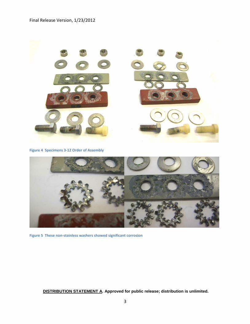
Final Release Version, 1/23/2012
DISTRIBUTION STATEMENT A. Approved for public release; distribution is unlimited.
3
Figure 4 Specimens 3-12 Order of Assembly
Figure 5 These non-stainless washers showed significant corrosion
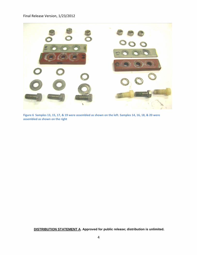
Final Release Version, 1/23/2012
DISTRIBUTION STATEMENT A. Approved for public release; distribution is unlimited.
4
Figure 6 Samples 13, 15, 17, & 19 were assembled as shown on the left. Samples 14, 16, 18, & 20 were assembled as shown on the right
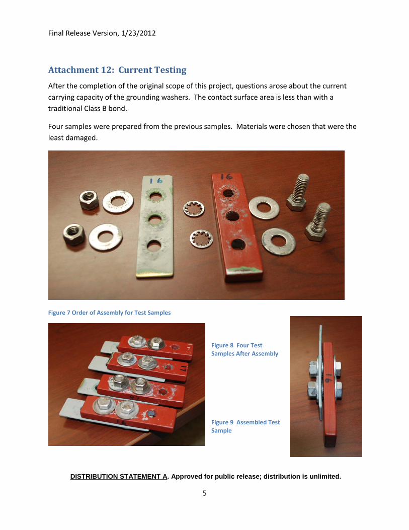
Final Release Version, 1/23/2012
DISTRIBUTION STATEMENT A. Approved for public release; distribution is unlimited.
5
Attachment 12: Current Testing
After the completion of the original scope of this project, questions arose about the current
carrying capacity of the grounding washers. The contact surface area is less than with a
traditional Class B bond.
Four samples were prepared from the previous samples. Materials were chosen that were the
least damaged.
Figure 7 Order of Assembly for Test Samples
Figure 8 Four Test Samples After Assembly
Figure 9 Assembled Test Sample
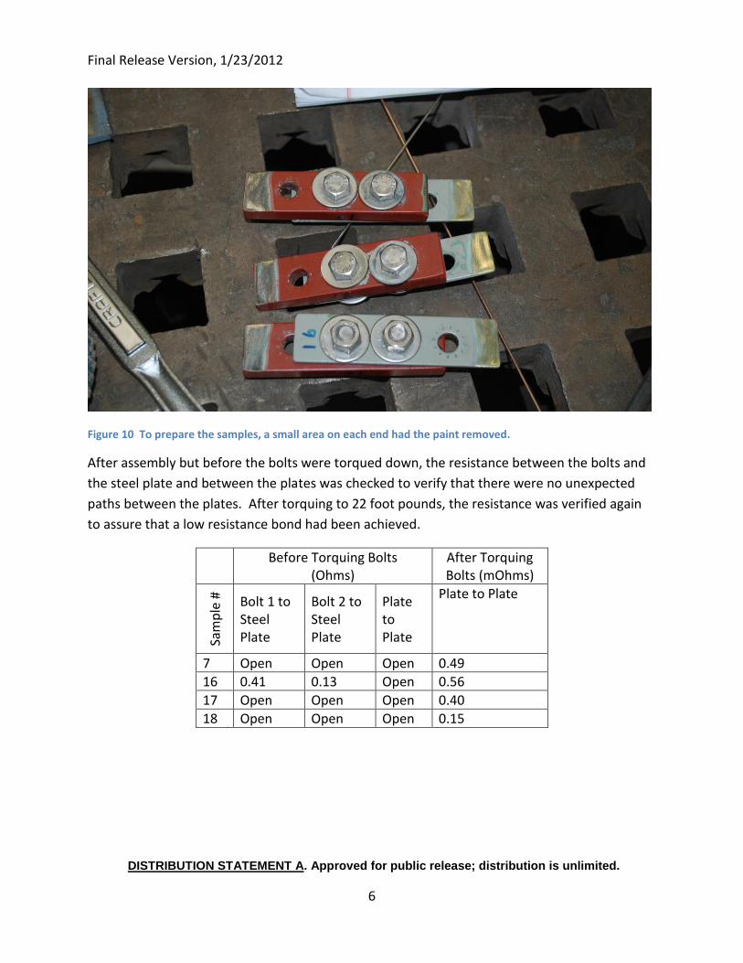
Final Release Version, 1/23/2012
DISTRIBUTION STATEMENT A. Approved for public release; distribution is unlimited.
6
Figure 10 To prepare the samples, a small area on each end had the paint removed.
After assembly but before the bolts were torqued down, the resistance between the bolts and
the steel plate and between the plates was checked to verify that there were no unexpected
paths between the plates. After torquing to 22 foot pounds, the resistance was verified again
to assure that a low resistance bond had been achieved.
Before Torquing Bolts (Ohms)
After Torquing Bolts (mOhms)
Sam
ple
#
Bolt 1 to Steel Plate
Bolt 2 to Steel Plate
Plate to Plate
Plate to Plate
7 Open Open Open 0.49
16 0.41 0.13 Open 0.56
17 Open Open Open 0.40
18 Open Open Open 0.15
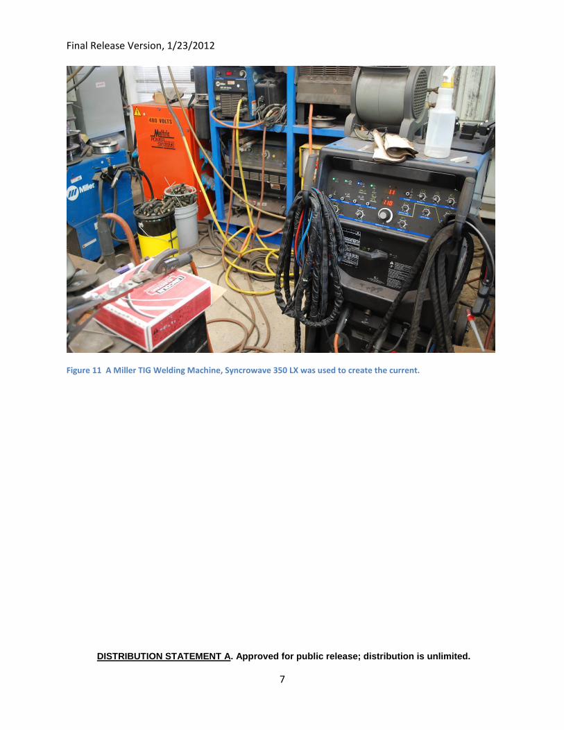
Final Release Version, 1/23/2012
DISTRIBUTION STATEMENT A. Approved for public release; distribution is unlimited.
7
Figure 11 A Miller TIG Welding Machine, Syncrowave 350 LX was used to create the current.
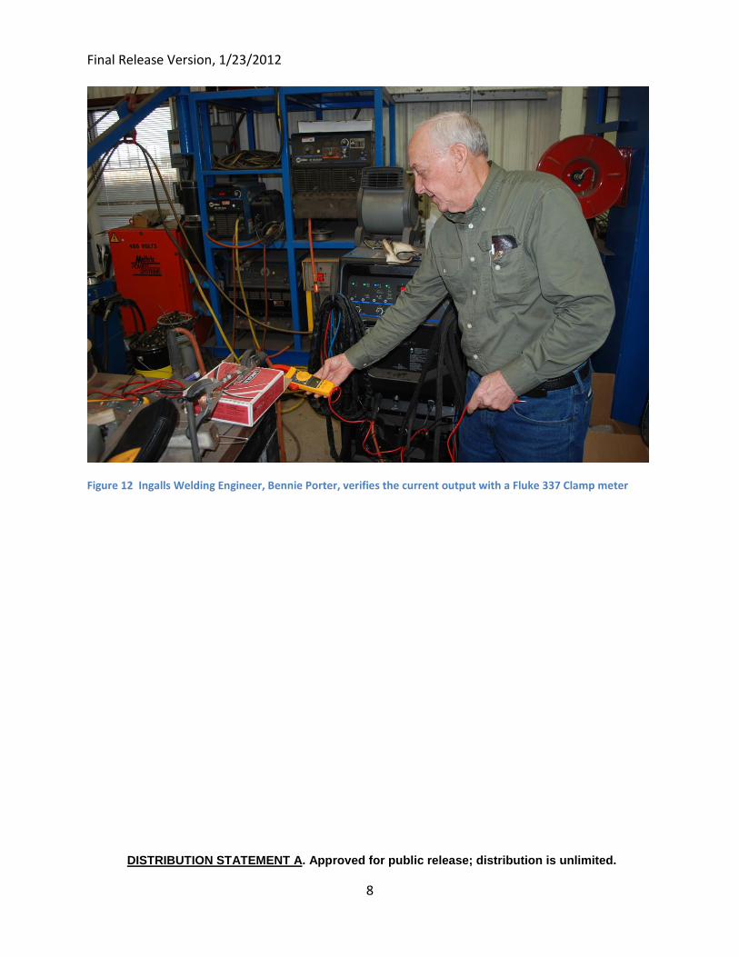
Final Release Version, 1/23/2012
DISTRIBUTION STATEMENT A. Approved for public release; distribution is unlimited.
8
Figure 12 Ingalls Welding Engineer, Bennie Porter, verifies the current output with a Fluke 337 Clamp meter
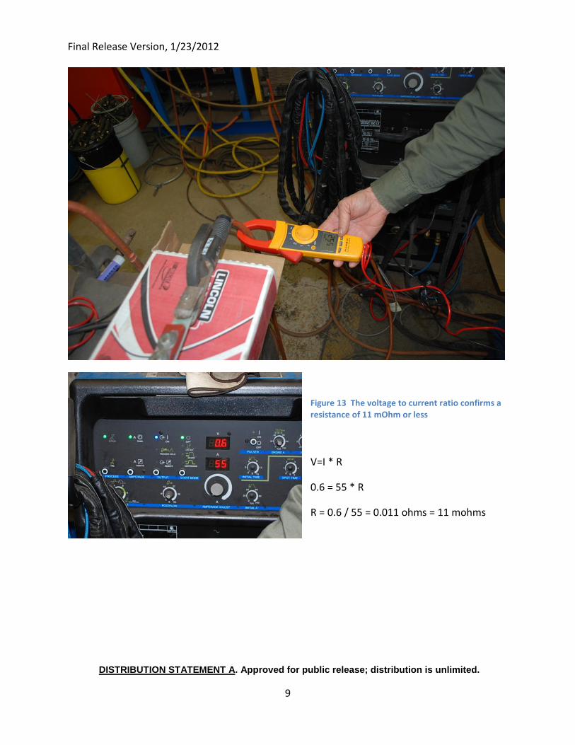
Final Release Version, 1/23/2012
DISTRIBUTION STATEMENT A. Approved for public release; distribution is unlimited.
9
Figure 13 The voltage to current ratio confirms a resistance of 11 mOhm or less
V=I * R
0.6 = 55 * R
R = 0.6 / 55 = 0.011 ohms = 11 mohms
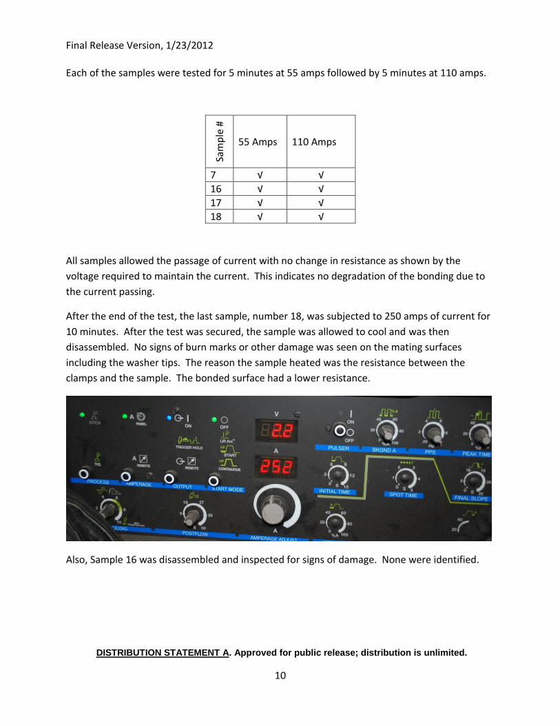
Final Release Version, 1/23/2012
DISTRIBUTION STATEMENT A. Approved for public release; distribution is unlimited.
10
Each of the samples were tested for 5 minutes at 55 amps followed by 5 minutes at 110 amps.
Sam
ple
#
55 Amps 110 Amps
7 √ √
16 √ √
17 √ √
18 √ √
All samples allowed the passage of current with no change in resistance as shown by the
voltage required to maintain the current. This indicates no degradation of the bonding due to
the current passing.
After the end of the test, the last sample, number 18, was subjected to 250 amps of current for
10 minutes. After the test was secured, the sample was allowed to cool and was then
disassembled. No signs of burn marks or other damage was seen on the mating surfaces
including the washer tips. The reason the sample heated was the resistance between the
clamps and the sample. The bonded surface had a lower resistance.
Also, Sample 16 was disassembled and inspected for signs of damage. None were identified.
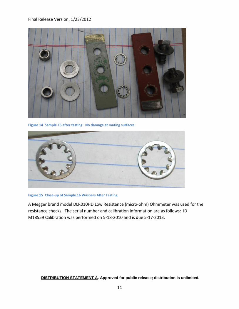
Final Release Version, 1/23/2012
DISTRIBUTION STATEMENT A. Approved for public release; distribution is unlimited.
11
Figure 14 Sample 16 after testing. No damage at mating surfaces.
Figure 15 Close-up of Sample 16 Washers After Testing
A Megger brand model DLR010HD Low Resistance (micro-ohm) Ohmmeter was used for the
resistance checks. The serial number and calibration information are as follows: ID
M18559 Calibration was performed on 5-18-2010 and is due 5-17-2013.
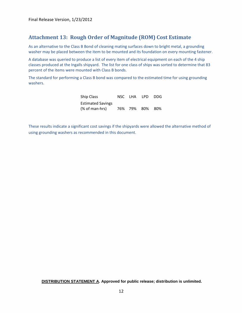
Final Release Version, 1/23/2012
DISTRIBUTION STATEMENT A. Approved for public release; distribution is unlimited.
12
Attachment 13: Rough Order of Magnitude (ROM) Cost Estimate
As an alternative to the Class B Bond of cleaning mating surfaces down to bright metal, a grounding washer may be placed between the item to be mounted and its foundation on every mounting fastener.
A database was queried to produce a list of every item of electrical equipment on each of the 4 ship classes produced at the Ingalls shipyard. The list for one class of ships was sorted to determine that 83 percent of the items were mounted with Class B bonds.
The standard for performing a Class B bond was compared to the estimated time for using grounding washers.
Ship Class NSC LHA LPD DDG
Estimated Savings (% of man-hrs) 76% 79% 80% 80%
These results indicate a significant cost savings if the shipyards were allowed the alternative method of
using grounding washers as recommended in this document.


