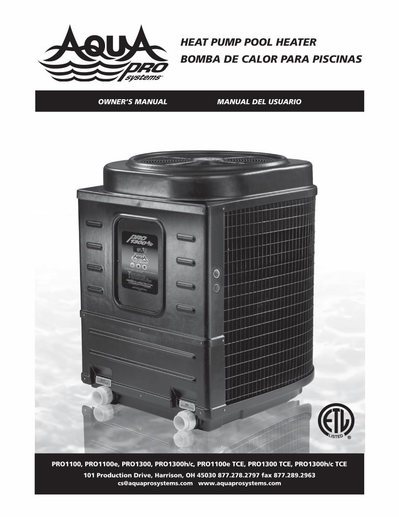
HEAT PUMP POOL HEATER
BOMBA DE CALOR PARA PISCINAS
PRO1100, PRO1100e, PRO1300, PRO1300h/c, PRO1100e TCE, PRO1300 TCE, PRO1300h/c TCE
101 Production Drive, Harrison, OH 45030 877.278.2797 fax [email protected] www.aquaprosystems.com
OWNER’S MANUAL MANUAL DEL USUARIO

.
REMINDER: Keep your dated proof of purchase for warranty purposes! Attach it to this manual or file it for safekeeping.
Please read and save these instructions. Read carefully before attempting to assemble, install, operate or maintain the product described.Protect yourself and others by observing all safety information. Failure to comply with instructions could result in personal injury and/orproperty damage! Retain instructions with owner for future reference.
Important Safety Instructions . . . . . . 1Installation Procedures . . . . . . . . . 1 - 2
Unit Inspection . . . . . . . . . . . . . . . . 1Unit Location . . . . . . . . . . . . . . . . . 2Plumbing . . . . . . . . . . . . . . . . . . . . . 2
Basic Heat Pump Operation . . . . . 2 - 3Electrical Connections . . . . . . . . 2 - 3Electronic Temp. Controls . . . . . . . . 3
- Description . . . . . . . . . . . . . . . . . 3- Buttons . . . . . . . . . . . . . . . . . . . . 3- Water Temp. Set Point . . . . . . . . 3
Connecting to a Remote System. . .3High Temperature Lock Out . . . . . . 3
SPECIFIC MODEL DETAILSPRO1100 . . . . . . . . . . . . . . . . . . . . . 4Wiring Diagram . . . . . . . . . . . . . . . . 4Manual Temp. Controls . . . . . . . . . 4
PRO1300 & PRO1100e . . . . . . . . . 5Wiring Diagram . . . . . . . . . . . . . . . . 5
PRO1300h/c . . . . . . . . . . . . . . . . 5 - 6Wiring Diagram . . . . . . . . . . . . . . . . 5Toggling Between Heat/ Cool Mode . . . . . . . . . . . . . . . . . . . 6
Defrost Cycle . . . . . . . . . . . . . . . . . . 6PRO1300 TCE/ PRO1100e TCE. . . . 6 - 7Selecting Functionality of Unit . . . . 6TCE Operation . . . . . . . . . . . . . . . . . 6TCO Operation . . . . . . . . . . . . . . 6 - 7Wiring Diagram . . . . . . . . . . . . . . . . 7
PRO1300h/c TCE . . . . . . . . . . . . 8 - 9Wiring Diagram . . . . . . . . . . . . . . . . 8Toggling Between Heat/ Cool Mode . . . . . . . . . . . . . . . . . . . 8
Defrost Cycle . . . . . . . . . . . . . . . . . . 8Selecting Functionality of Unit . . . . 8TCE Operation . . . . . . . . . . . . . . 8 - 9TCO Operation . . . . . . . . . . . . . . . . 9
Application Guidelines . . . . . . . . 9 - 10Maintenance . . . . . . . . . . . . . . . . . . 9Condensation . . . . . . . . . . . . . 9 - 10Pool Blankets . . . . . . . . . . . . . . . . 10Seasonal Shutdowns . . . . . . . . . . 10Pool Openings . . . . . . . . . . . . . . . 10Weather Conditions . . . . . . . . . . . 10
Troubleshooting Guide . . . . . . . 10 - 11- Diagnostics . . . . . . . . . . . . . 10 - 11
Warranty . . . . . . . . . . . . . . . . . . . . . . 12
322902-013 2/08© 2008 AquaPRO® Systems For parts, product & service informationvisit www.aquaprosystems.com
Important SafetyInstructionsREAD AND FOLLOW ALLINSTRUCTIONS.Safety GuidelinesThis manual contains information that isvery important to know and understand.This information is provided for SAFETYand to PREVENT EQUIPMENT PROBLEMS.To help recognize this information,observe the following symbols.
Warningindicates a
potentially hazardous situation which, ifnot avoided, could result in death orserious injury.
Caution indicates a
potentially hazardous situation which, ifnot avoided, may result in minor ormoderate injury.
Notice indicates
important information, that if notfollowed, may cause damage toequipment.
CALIFORNIA PROPOSITION 65Thisproduct or
its power cord may contain chemicalsknown to the State of California tocause cancer and birth defects or otherreproductive harm. Wash hands afterhandling.
GENERAL SAFETY INFORMATION
• The water in a pool or tub should neverexceed 104ºF (40ºC). A watertemperature in excess of 104ºF isconsidered unsafe for all persons. Lowerwater temperatures are recommendedfor extended use (exceeding 10 - 15minutes) and young children.
• Excessive water temperatures have ahigh potential for causing fetal damageduring the early months of pregnancy.Pregnant or possibly pregnant womenshould limit pool or tub watertemperatures to 100ºF (38ºC).
• Alcohol, drugs, or medication shouldnot be used before or during pool ortub use since their use may lead to
unconsciousness with the possibilityof drowning.
• Obese persons and persons with amedical history of heart disease, low orhigh blood pressure, circulatory systemproblems, or diabetes should consult aphysician before using a pool or tub.
• Persons using medication shouldconsult a physician before using a poolor tub since some medication mayinduce drowsiness while othermedication may affect heart rate,blood pressure, and circulation.
• Prolonged immersion in hot water mayinduce hyperthermia. Hyperthermiaoccurs when the internal temperatureof the body reaches a level severaldegrees above the normal bodytemperature of 98.6ºF. The symptomsof hyperthermia include dizziness,fainting, drowsiness, lethargy, and anincrease in the internal temperature ofthe body. The effects of hyperthermiainclude: unawareness of impendinghazard; failure to perceive heat; failureto recognize the need to exit pool ortub; physical inability to exit pool ortub; fetal damage in pregnant women;and unconsciousness resulting in adanger of drowning.
• Because the tolerance of watertemperature-regulating devices mayvary as much as ±5ºF (±3ºC), youshould measure the watertemperature at several locationsusing an accurate thermometerbefore entering a pool or tub.
SAVE THESE INSTRUCTIONS.
Installation ProceduresUnit InspectionInspect your unit very carefully beforeinstalling. Make sure there has beenno damage to the evaporator fins orthere are no punctures or oil-soakedareas on the box. This would indicatedamage to the refrigeration systemand should be rejected immediately.
Contents
Heat Pump Pool and Spa Heater
Operating Instructions PRO1300, PRO1100e, PRO1300h/c, PRO1100,PRO1300h/c TCE, PRO1300 TCE, PRO1100e TCE
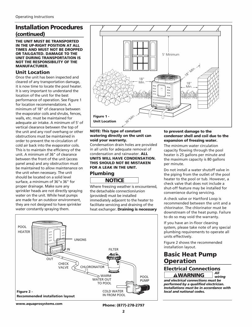
Figure 2 -Recommended installation layout
POOL
HEATER
UNIONS
FILTER
POOLPUMP
CHLORONATOR
WARMWATER OUT
TO POOL
COLD WATERIN FROM POOL
IN
OUTCHECK VALVE
THE UNIT MUST BE TRANSPORTEDIN THE UP-RIGHT POSITION AT ALLTIMES AND MUST NOT BE DROPPEDOR TAILGATED. DAMAGE TO THEUNIT DURING TRANSPORTATION ISNOT THE RESPONSIBILITY OF THEMANUFACTURER.
Unit LocationOnce the unit has been inspected andcleared of any transportation damage,it is now time to locate the pool heater.It is very important to understand thelocation of the unit for the bestperformance of operation. See Figure 1for location recommendations. Aminimum of 18" of clearance betweenthe evaporator coils and shrubs, fences,walls, etc. must be maintained foradequate air intake. A minimum of 5' ofvertical clearance between the top ofthe unit and any roof overhang or otherobstructions must be maintained inorder to prevent the re-circulation ofcold air back into the evaporator coils.This is to maintain the efficiency of theunit. A minimum of 36" of clearancebetween the front of the unit (accesspanel area) and any obstruction mustbe maintained to allow maintenance onthe unit when necessary. The unitshould be located on a solid levelsurface, a minimum of 36"x 36" forproper drainage. Make sure anysprinkler heads are not directly sprayingwater on the unit. While heat pumpsare made for an outdoor environment,they are not designed to have sprinklerwater constantly spraying them.
NOTE: This type of constantwatering directly on the unit canvoid your warranty.Condensation drain holes are providedin all units for adequate removal ofcondensation and rainwater. ALLUNITS WILL HAVE CONDENSATION.THIS SHOULD NOT BE MISTAKENFOR A LEAK IN THE UNIT.
Plumbing
Where freezing weather is encountered,the detachable connection/union(provided) must be installedimmediately adjacent to the heater tofacilitate servicing and draining of theheat exchanger. Draining is necessary
Phone: (877)-278-2797
2
Operating Instructions
to prevent damage to thecondenser shell and coil due to theexpansion of freezing water.The minimum water circulationcapacity flowing through the poolheater is 25 gallons per minute andthe maximum capacity is 80 gallonsper minute.
Do not install a water shutoff valve inthe piping from the outlet of the poolheater to the pool or tub. However, acheck valve that does not include ashut-off feature may be installed forconvenience during servicing.
A check valve or Hartford Loop isrecommended between the unit and achlorinator. The chlorinator must bedownstream of the heat pump. Failureto do so may void the warranty.
If you have an in-floor cleaningsystem, please take note of any specialplumbing requirements to operate allunits effectively.
Figure 2 shows the recommendedinstallation layout.
Basic Heat PumpOperationElectrical Connections
All wiring
and electrical connections must beperformed by a qualified electrician.Installations must be in accordance withlocal and national codes.
www.aquaprosystems.com
5 feet (minimum)
18“ min
18“ min
18“ min
36” clearance
5' Minimum
18" Min.
18"Min.
36"M
in.
18"Min.
Figure 1 -Unit Location
Installation Procedures(continued)
www.aquaprosystems.com
Overheating, short-circuiting and firedamage will result from inadequatewiring.All units are equipped with anelectrical wiring schematic inside theelectrical panel. If this is missing,please contact the factory at 1-877-278-2797 to obtain one.
All units are to be wired for 230 VAC, 1phase. These units require a dedicated50-amp breaker or time delay fuse.
Pool Heater is to be installed inaccordance with Article 680 of theNational Electrical Code (NEC), NFPA70, and within the requirements of alllocal codes having jurisdiction.
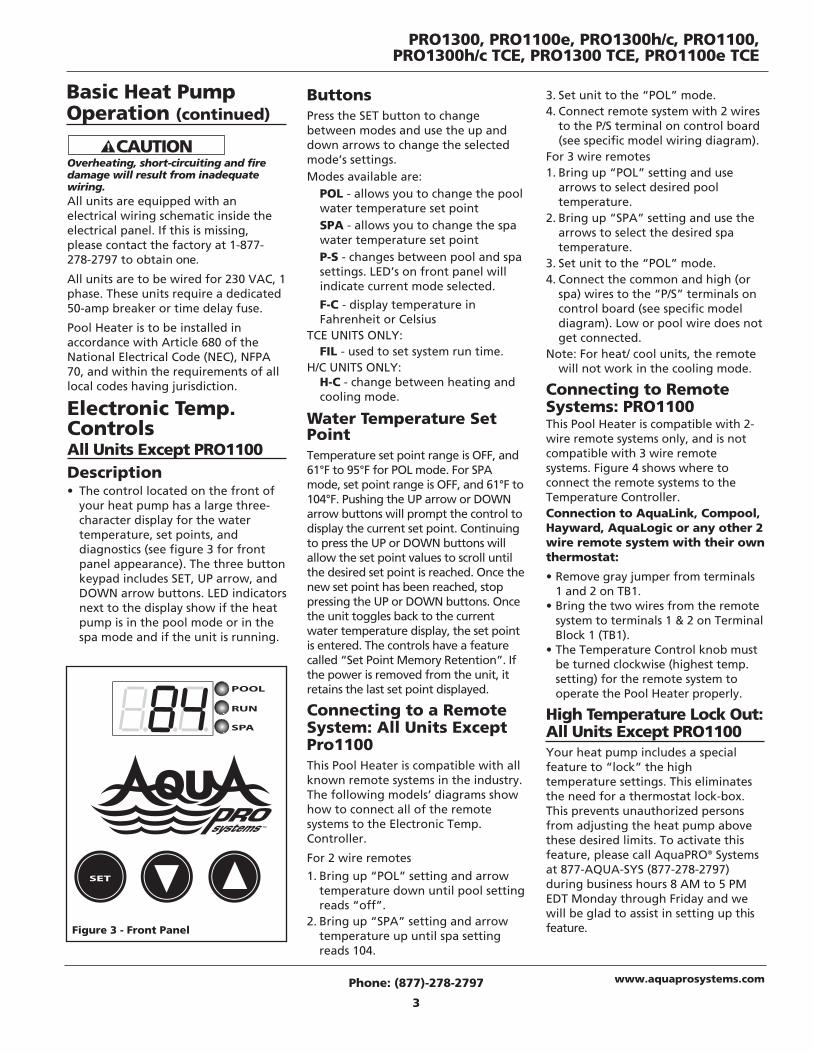
Electronic Temp.Controls All Units Except PRO1100Description• The control located on the front of
your heat pump has a large three-character display for the watertemperature, set points, anddiagnostics (see figure 3 for frontpanel appearance). The three buttonkeypad includes SET, UP arrow, andDOWN arrow buttons. LED indicatorsnext to the display show if the heatpump is in the pool mode or in thespa mode and if the unit is running.
ButtonsPress the SET button to changebetween modes and use the up anddown arrows to change the selectedmode’s settings.Modes available are:
POL - allows you to change the poolwater temperature set pointSPA - allows you to change the spawater temperature set pointP-S - changes between pool and spasettings. LED’s on front panel willindicate current mode selected.
F-C - display temperature inFahrenheit or Celsius
TCE UNITS ONLY:FIL - used to set system run time.
H/C UNITS ONLY:H-C - change between heating andcooling mode.
Water Temperature SetPointTemperature set point range is OFF, and61°F to 95°F for POL mode. For SPAmode, set point range is OFF, and 61°F to104°F. Pushing the UP arrow or DOWNarrow buttons will prompt the control todisplay the current set point. Continuingto press the UP or DOWN buttons willallow the set point values to scroll untilthe desired set point is reached. Once thenew set point has been reached, stoppressing the UP or DOWN buttons. Oncethe unit toggles back to the currentwater temperature display, the set pointis entered. The controls have a featurecalled “Set Point Memory Retention”. Ifthe power is removed from the unit, itretains the last set point displayed.
Connecting to a RemoteSystem: All Units ExceptPro1100This Pool Heater is compatible with allknown remote systems in the industry.The following models’ diagrams showhow to connect all of the remotesystems to the Electronic Temp.Controller.
For 2 wire remotes
1. Bring up “POL” setting and arrowtemperature down until pool settingreads “off”.
2. Bring up “SPA” setting and arrowtemperature up until spa settingreads 104.
3. Set unit to the “POL” mode.4. Connect remote system with 2 wires
to the P/S terminal on control board(see specific model wiring diagram).
For 3 wire remotes1. Bring up “POL” setting and use
arrows to select desired pooltemperature.
2. Bring up “SPA” setting and use thearrows to select the desired spatemperature.
3. Set unit to the “POL” mode.4. Connect the common and high (or
spa) wires to the “P/S” terminals oncontrol board (see specific modeldiagram). Low or pool wire does notget connected.
Note: For heat/ cool units, the remotewill not work in the cooling mode.
Connecting to RemoteSystems: PRO1100 This Pool Heater is compatible with 2-wire remote systems only, and is notcompatible with 3 wire remotesystems. Figure 4 shows where toconnect the remote systems to theTemperature Controller.Connection to AquaLink, Compool,Hayward, AquaLogic or any other 2wire remote system with their ownthermostat:
• Remove gray jumper from terminals1 and 2 on TB1.
• Bring the two wires from the remotesystem to terminals 1 & 2 on TerminalBlock 1 (TB1).
• The Temperature Control knob mustbe turned clockwise (highest temp.setting) for the remote system tooperate the Pool Heater properly.
High Temperature Lock Out:All Units Except PRO1100Your heat pump includes a specialfeature to “lock” the hightemperature settings. This eliminatesthe need for a thermostat lock-box.This prevents unauthorized personsfrom adjusting the heat pump abovethese desired limits. To activate thisfeature, please call AquaPRO® Systemsat 877-AQUA-SYS (877-278-2797)during business hours 8 AM to 5 PMEDT Monday through Friday and wewill be glad to assist in setting up thisfeature.
PRO1300, PRO1100e, PRO1300h/c, PRO1100,PRO1300h/c TCE, PRO1300 TCE, PRO1100e TCE
Phone: (877)-278-2797
3
Figure 3 - Front Panel
Basic Heat PumpOperation (continued)
Operating Instructions
www.aquaprosystems.com
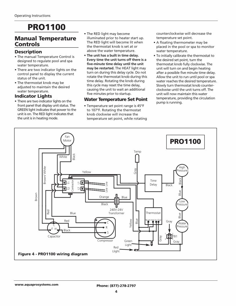
Manual TemperatureControls Description• The manual Temperature Control is
designed to regulate pool and spawater temperature.
• There are two indicator lights on thecontrol panel to display the currentstatus of the unit.
• The thermostat knob may beadjusted to maintain the desiredwater temperature.
Indicator Lights• There are two indicator lights on the
front panel that display unit status. TheGREEN light indicates that power to theunit is on. The RED light indicates thatthe unit is in heating mode.
Phone: (877)-278-2797
4
Figure 4 - PRO1100 wiring diagram
PRO1100• The RED light may become
illuminated prior to heater start up.The RED light will become lit whenthe thermostat knob is set at orabove the water temperature.
• The unit has a built in time delay.Every time the unit turns off there is afive-minute time delay until the unitmay be restarted. The HEAT light mayturn on during this delay cycle. Do notrotate the thermostat knob during thistime delay. Rotating the knob duringthis cycle may reset the time delay,causing the unit to wait an additionalfive minutes prior to startup.
Water Temperature Set Point• Temperature set point range is 45°F
to 107°F. Rotating the thermostatknob clockwise will increase thetemperature set point, while rotating
counterclockwise will decrease thetemperature set point.
• A floating thermometer may beplaced in the pool or spa to monitorwater temperature.
• To initially calibrate the thermostat tothe desired set point, turn thethermostat knob fully clockwise. Theunit will turn on and begin heatingafter a possible five minute time delay.Allow the unit to run until pool or spawater reaches the desired temperature.Slowly turn thermostat knob counter-clockwise until the unit turns off. Theunit will now maintain this watertemperature, providing the circulationpump is running.
FanMotor
GreenLight
RedLlight
240V-24VTransformer
CapacitorCompressor
Thermostat
TimeDelay
WaterPressure
LowPressure
HighPressure
Blac
k
Blac
k
Black
Black
Black
White
Brow
n/ W
hite
Brow
n
Blue
Blue
Blue
Blue
Blue
Yel
low
Yellow Gra
y
Gray
GrayGra
y
Red
Red
Orange
Nuet Hot In Out
T2
T1
Con
trac
tor
L2
L1
Line
Lin
e
Temp
1 2
TB13 4
CF H
C
R
S
PRO1100
PRO1300, PRO1100e, PRO1300h/c, PRO1100,PRO1300h/c TCE, PRO1300 TCE, PRO1100e TCE
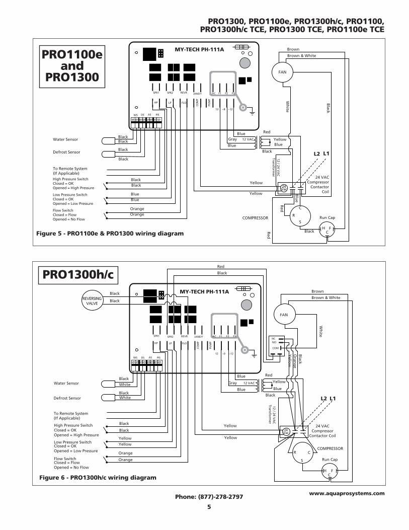
Figure 5 - PRO1100e & PRO1300 wiring diagram
Water Sensor
Defrost Sensor
High Pressure SwitchClosed = OKOpened = High Pressure
Low Pressure SwitchClosed = OKOpened = Low Pressure
Flow SwitchClosed = FlowOpened = No Flow
MY-TECH PH-111A Brown
Brown & White
SPR1 SPR2 REVR JANDY
HP LP FLO
COM
P
PUM
P
12 ~8 ~12
AC F1 F2 F3
WS DS AS P/S
BlackBlack
Blue
Orange
Blue
Orange
BlueGray 12 VAC
Blue
Red
Blue
12 / 24 VA
CTran
sform
er
Black
Yellow
Yellow
24Vac
COMPRESSORR
S
C
24 VACCompressor
ContactorCoil
Run Cap
L1L2
Black
Black
Yellow
Black
Black Red
HC
F
Red
Blu
e
FAN
Black
Black
Wh
ite
PRO1100eand
PRO1300
Phone: (877)-278-2797
5
www.aquaprosystems.com
To Remote System(If Applicable)
Figure 6 - PRO1300h/c wiring diagram
Water Sensor
Defrost Sensor
High Pressure SwitchClosed = OKOpened = High Pressure
Low Pressure SwitchClosed = OKOpened = Low Pressure
Flow SwitchClosed = FlowOpened = No Flow
Red
Black
MY-TECH PH-111A Brown
Brown & White
FAN
SPR1 SPR2 REVR JANDY
HP LP FLO
COM
P
PUM
P
12 ~0 ~12
AC F1 F2 F3
WS DS AS P/S
White
White
Black
Black
Yellow
Orange
Yellow
Orange
Blue
Gray 12 VAC
Blue
Red
Blue
12 / 24 VA
CTran
sform
er
Black
Yellow
Yellow
Yellow
24Vac
COMPRESSORR
S
C
24 VACCompressor
Contactor Coil
Run Cap
L1L2
REVERSINGVALVE
Black
Black
NCNO
COM
Black
Black
Wh
ite
Yello
w
Black
Oran
ge
HC
F
To Remote System(If Applicable)
PRO1300h/c
Operating Instructions
Phone: (877)-278-2797
6
www.aquaprosystems.com
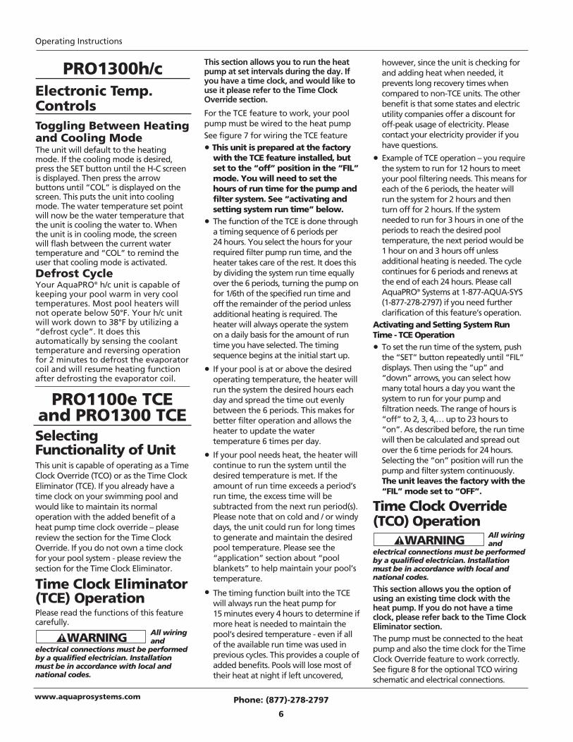
PRO1300h/cElectronic Temp.ControlsToggling Between Heatingand Cooling ModeThe unit will default to the heatingmode. If the cooling mode is desired,press the SET button until the H-C screenis displayed. Then press the arrowbuttons until “COL” is displayed on thescreen. This puts the unit into coolingmode. The water temperature set pointwill now be the water temperature thatthe unit is cooling the water to. Whenthe unit is in cooling mode, the screenwill flash between the current watertemperature and “COL” to remind theuser that cooling mode is activated.Defrost CycleYour AquaPRO® h/c unit is capable ofkeeping your pool warm in very cooltemperatures. Most pool heaters willnot operate below 50°F. Your h/c unitwill work down to 38°F by utilizing a“defrost cycle”. It does thisautomatically by sensing the coolanttemperature and reversing operationfor 2 minutes to defrost the evaporatorcoil and will resume heating functionafter defrosting the evaporator coil.
This section allows you to run the heatpump at set intervals during the day. Ifyou have a time clock, and would like touse it please refer to the Time ClockOverride section.
For the TCE feature to work, your poolpump must be wired to the heat pump See figure 7 for wiring the TCE feature
• This unit is prepared at the factorywith the TCE feature installed, butset to the “off” position in the “FIL”mode. You will need to set thehours of run time for the pump andfilter system. See “activating andsetting system run time” below.
• The function of the TCE is done througha timing sequence of 6 periods per24 hours. You select the hours for yourrequired filter pump run time, and theheater takes care of the rest. It does thisby dividing the system run time equallyover the 6 periods, turning the pump onfor 1/6th of the specified run time andoff the remainder of the period unlessadditional heating is required. Theheater will always operate the systemon a daily basis for the amount of runtime you have selected. The timingsequence begins at the initial start up.
• If your pool is at or above the desiredoperating temperature, the heater willrun the system the desired hours eachday and spread the time out evenlybetween the 6 periods. This makes forbetter filter operation and allows theheater to update the watertemperature 6 times per day.
• If your pool needs heat, the heater willcontinue to run the system until thedesired temperature is met. If theamount of run time exceeds a period’srun time, the excess time will besubtracted from the next run period(s).Please note that on cold and / or windydays, the unit could run for long timesto generate and maintain the desiredpool temperature. Please see the“application” section about “poolblankets” to help maintain your pool’stemperature.
• The timing function built into the TCEwill always run the heat pump for15 minutes every 4 hours to determine ifmore heat is needed to maintain thepool’s desired temperature - even if allof the available run time was used inprevious cycles. This provides a couple ofadded benefits. Pools will lose most oftheir heat at night if left uncovered,
however, since the unit is checking forand adding heat when needed, itprevents long recovery times whencompared to non-TCE units. The otherbenefit is that some states and electricutility companies offer a discount foroff-peak usage of electricity. Pleasecontact your electricity provider if youhave questions.
• Example of TCE operation – you requirethe system to run for 12 hours to meetyour pool filtering needs. This means foreach of the 6 periods, the heater willrun the system for 2 hours and thenturn off for 2 hours. If the systemneeded to run for 3 hours in one of theperiods to reach the desired pooltemperature, the next period would be1 hour on and 3 hours off unlessadditional heating is needed. The cyclecontinues for 6 periods and renews atthe end of each 24 hours. Please callAquaPRO® Systems at 1-877-AQUA-SYS(1-877-278-2797) if you need furtherclarification of this feature’s operation.
Activating and Setting System RunTime - TCE Operation
• To set the run time of the system, pushthe “SET” button repeatedly until “FIL”displays. Then using the “up” and“down” arrows, you can select howmany total hours a day you want thesystem to run for your pump andfiltration needs. The range of hours is“off” to 2, 3, 4,… up to 23 hours to“on”. As described before, the run timewill then be calculated and spread outover the 6 time periods for 24 hours.Selecting the “on” position will run thepump and filter system continuously.The unit leaves the factory with the“FIL” mode set to “OFF”.
Time Clock Override(TCO) Operation
All wiring and
electrical connections must be performedby a qualified electrician. Installationmust be in accordance with local andnational codes.
This section allows you the option ofusing an existing time clock with theheat pump. If you do not have a timeclock, please refer back to the Time ClockEliminator section.The pump must be connected to the heatpump and also the time clock for the TimeClock Override feature to work correctly.See figure 8 for the optional TCO wiringschematic and electrical connections.
PRO1100e TCEand PRO1300 TCESelectingFunctionality of UnitThis unit is capable of operating as a TimeClock Override (TCO) or as the Time ClockEliminator (TCE). If you already have atime clock on your swimming pool andwould like to maintain its normaloperation with the added benefit of aheat pump time clock override – pleasereview the section for the Time ClockOverride. If you do not own a time clockfor your pool system - please review thesection for the Time Clock Eliminator.
Time Clock Eliminator(TCE) OperationPlease read the functions of this featurecarefully.
All wiring and
electrical connections must be performedby a qualified electrician. Installationmust be in accordance with local andnational codes.

Figure 7 - PRO1100e TCE & PRO1300 TCE wiring diagram
Water Sensor
Defrost Sensor
High Pressure SwitchClosed = OKOpened = High Pressure
Low Pressure SwitchClosed = OKOpened = Low Pressure
Flow SwitchClosed = FlowOpened = No Flow
MY-TECH PH-111A Brown
Brown & White
SPR1 SPR2 REVR JANDY
HP LP FLO
COM
P
PUM
P
12 ~8 ~12
AC F1 F2 F3
WS DS AS P/S
Black
Black
Blue
Orange
Blue
Orange
Blue
Gray 12 VAC
Blue
Red
Blue
12 / 24 VA
C Tran
sform
er
Black
YellowYellow
24Vac
COMPRESSOR
R
S
C
24 VACCompressor
Contactor Coil
Run Cap
L1L2
Black
Black
Yellow
Black
Black
Red H
CF
Red
Blu
e
FAN
Black
Black
Wh
ite
24 VAC
pool pumpcontactor coil
L4
Pool Pump
L3
PRO1300, PRO1100e, PRO1300h/c, PRO1100,PRO1300h/c TCE, PRO1300 TCE, PRO1100e TCE
Phone: (877)-278-2797
7
www.aquaprosystems.com
To Remote System(If Applicable)
•This unit is prepared at the factory withthe “FIL” mode set to the “off” position.You will need to set the heat pump’shours of run time in the “FIL” mode to“2” hours. See “activating and settingsystem run time” below to set the runtime. Leave your time clock set to thedesired pump and filter operation time.This will enable the heat pump and filtersystem to run the desired hours of theday and also provide the benefit ofchecking if heat is needed every 4 hours.It will do this by running the pump andfilter system for 15 minutes. If heat isneeded, it will continue to run until thepool has reached the set temperature. Ifno heat is needed, the system will turnoff and continue checking for heat every4 hours. This provides a couple of addedbenefits. Pools will lose most of theirheat at night if left uncovered, however,since the unit is checking for and adding
heat when needed, it prevents longrecovery times when compared to non-TCO units. The other benefit is that somestates and electric utility companies offera discount for off-peak usage ofelectricity. Please contact your electricityprovider if you have questions.
Activating and Setting System RunTime – TCO Operation
•To set the run time of the system,push the “SET” button repeatedlyuntil “FIL” displays. Then using the“up” and “down” arrows, set thehours to “2”. The range of hours is“off” to 2, 3, 4,… up to 23 hours to“on”. By selecting “2” the heat pumpwill run every 4 hours for 20 minutes,checking if heat is needed. The unitleaves the factory with the “FIL”mode set to “OFF”.
Time Clock Override(TCO) Operation (cont.)
BREAKER
TIME CLOCK
FILTER PUMP
CONTACTOR FOR THE
TIME CLOCK
OVERRIDE
INSIDE HEAT PUMP
T2 T1
L3 L4
INSIDEHEATPUMP
CONTACTORFOR THE
TIME CLOCKOVERRIDE
TIMECLOCK
FILTERPUMP
BREAKER
Figure 8 - TCO wiring diagram(optional)
PRO1100eTCE and
PRO1300TCE
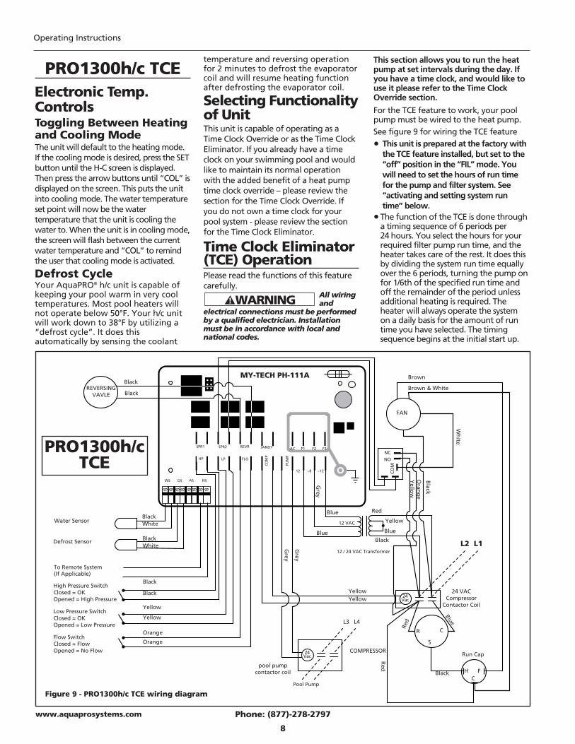
Water Sensor
Defrost Sensor
High Pressure SwitchClosed = OKOpened = High Pressure
Low Pressure SwitchClosed = OKOpened = Low Pressure
Flow SwitchClosed = FlowOpened = No Flow
MY-TECH PH-111A Brown
Brown & White
SPR1 SPR2 REVR JANDY
HP LP FLO
COM
P
PUM
P
12 ~8 ~12
AC F1 F2 F3
WS DS AS P/S
Black
Black
Yellow
Orange
Yellow
Orange
Blue
12 VAC
Blue
Red
Blue
12 / 24 VAC Transformer
Black
YellowYellow 24
Vac
COMPRESSOR
R
S
C
24 VACCompressor
Contactor Coil
Run Cap
L1L2
Black
Black
Yellow
Black
Black
Red
HC
F
Red
Blue
FAN
White
White
Wh
ite
pool pumpcontactor coil
L4
Pool Pump
L3
Grey
Grey
24Vac
Grey
Oran
ge
Yello
w
NCNO
CO
M
Black
BlackREVERSING
VAVLE
Figure 9 - PRO1300h/c TCE wiring diagram
Operating Instructions
Electronic Temp.ControlsToggling Between Heatingand Cooling ModeThe unit will default to the heating mode.If the cooling mode is desired, press the SETbutton until the H-C screen is displayed.Then press the arrow buttons until “COL” isdisplayed on the screen. This puts the unitinto cooling mode. The water temperatureset point will now be the watertemperature that the unit is cooling thewater to. When the unit is in cooling mode,the screen will flash between the currentwater temperature and “COL” to remindthe user that cooling mode is activated.
Defrost CycleYour AquaPRO® h/c unit is capable ofkeeping your pool warm in very cooltemperatures. Most pool heaters willnot operate below 50°F. Your h/c unitwill work down to 38°F by utilizing a“defrost cycle”. It does thisautomatically by sensing the coolant
temperature and reversing operationfor 2 minutes to defrost the evaporatorcoil and will resume heating functionafter defrosting the evaporator coil.
Selecting Functionalityof UnitThis unit is capable of operating as aTime Clock Override or as the Time ClockEliminator. If you already have a timeclock on your swimming pool and wouldlike to maintain its normal operationwith the added benefit of a heat pumptime clock override – please review thesection for the Time Clock Override. Ifyou do not own a time clock for yourpool system - please review the sectionfor the Time Clock Eliminator.
Time Clock Eliminator(TCE) OperationPlease read the functions of this featurecarefully.
All wiring and
electrical connections must be performedby a qualified electrician. Installationmust be in accordance with local andnational codes.
Phone: (877)-278-2797
8
www.aquaprosystems.com
To Remote System(If Applicable)
This section allows you to run the heatpump at set intervals during the day. Ifyou have a time clock, and would like touse it please refer to the Time ClockOverride section.
For the TCE feature to work, your poolpump must be wired to the heat pump. See figure 9 for wiring the TCE feature
• This unit is prepared at the factory withthe TCE feature installed, but set to the“off” position in the “FIL” mode. Youwill need to set the hours of run timefor the pump and filter system. See“activating and setting system runtime” below.
•The function of the TCE is done througha timing sequence of 6 periods per24 hours. You select the hours for yourrequired filter pump run time, and theheater takes care of the rest. It does thisby dividing the system run time equallyover the 6 periods, turning the pump onfor 1/6th of the specified run time andoff the remainder of the period unlessadditional heating is required. Theheater will always operate the systemon a daily basis for the amount of runtime you have selected. The timingsequence begins at the initial start up.
PRO1300h/c TCE
PRO1300h/cTCE
• If your pool is at or above the desiredoperating temperature, the heater willrun the system the desired hours eachday and spread the time out evenlybetween the 6 periods. This makes forbetter filter operation and allows theheater to update the watertemperature 6 times per day.
• If your pool needs heat, the heater willcontinue to run the system until thedesired temperature is met. If theamount of run time exceeds a period’srun time, the excess time will besubtracted from the next run period(s).Please note that on cold and / or windydays, the unit could run for long timesto generate and maintain the desiredpool temperature. Please see the“application” section about “poolblankets” to help maintain your pool’stemperature.
•The timing function built into the TCE willalways run the heat pump for 15 minutesevery 4 hours to determine if more heat isneeded to maintain the pool’s desiredtemperature - even if all of the availablerun time was used in previous cycles. Thisprovides a couple of added benefits.Pools will lose most of their heat at nightif left uncovered, however, since the unitis checking for and adding heat whenneeded, it prevents long recovery timeswhen compared to non-TCE units. Theother benefit is that some states andelectric utility companies offer a discountfor off-peak usage of electricity. Pleasecontact your electricity provider if youhave questions.
•Example of TCE operation– you requirethe system to run for 12 hours to meetyour pool filtering needs. This meansfor each of the 6 periods, the heater willrun the system for 2 hours and thenturn off for 2 hours. If the systemneeded to run for 3 hours in one of theperiods to reach the desired pooltemperature, the next period would be1 hour on and 3 hours off unlessadditional heating is needed. The cyclecontinues for 6 periods and renews atthe end of each 24 hours. Please callAquaPRO® Systems at 1-877-AQUA-SYS(1-877-278-2797) if you need furtherclarification of this feature’s operation.
Activating and Setting system run time
• To set the run time of the system, pushthe “SET” button repeatedly until “FIL”displays. Then using the “up” and
“down” arrows, you can select howmany total hours a day you want thesystem to run for your pump andfiltration needs. The range of hours is“off” to 2, 3, 4,… up to 23 hours to“on”. As described before, the run timewill then be calculated and spread outover the 6 time periods for 24 hours.Selecting the “on” position will run thepump and filter system continuously.The unit leaves the factory with the“FIL” mode set to “OFF”.
Time Clock Override(TCO) Operation
All wiring and
electrical connections must be performedby a qualified electrician. Installationmust be in accordance with local andnational codes.
This section allows you the option ofusing an existing time clock with theheat pump. If you do not have a timeclock, please refer back to the Time ClockEliminator section.The pump must be connected to the heatpump and also the time clock for the TimeClock Override feature to work correctly.See the optional TCO wiring schematic forelectrical connections.
•This unit is prepared at the factory withthe “FIL” mode set to the “off” position.You will need to set the heat pump’shours of run time in the “FIL” mode to“2” hours. See “activating and settingsystem run time” below to set the runtime. Leave your time clock set to thedesired pump and filter operation time.This will enable the heat pump andfilter system to run the desired hours of
the day and also provide the benefit ofchecking if heat is needed every 4 hours.It will do this by running the pump andfilter system for 20 minutes. If heat isneeded, it will continue to run until thepool has reached the set temperature. Ifno heat is needed, the system will turnoff and continue checking for heatevery 4 hours. This provides a couple ofadded benefits. Pools will lose most oftheir heat at night if left uncovered,however, since the unit is checking forand adding heat when needed, itprevents long recovery times whencompared to non-TCO units. The otherbenefit is that some states and electricutility companies offer a discount foroff-peak usage of electricity. Pleasecontact your electricity provider if youhave questions.
Activating and Setting System RunTime – TCO Operation
• To set the run time of the system, pushthe “SET” button repeatedly until “FIL”displays. Then using the “up” and“down” arrows, set the hours to “2”.The range of hours is “off” to 2, 3, 4,…up to 23 hours to “on”. By selecting “2”the heat pump will run every 4 hoursfor 20 minutes, checking if heat isneeded. The unit leaves the factorywith the “FIL” mode set to “OFF”.
ApplicationGuidelines (All Models)
MaintenanceAll heat pumps are designed for outdooruse. However, some maintenance isrequired to maintain the full life of theheater and is necessary to maintain yourwarranty. Annual maintenance should bescheduled to make sure blowing sand orfalling debris is removed from the inside ofthe heater. Also, rinsing the coil down,monthly, with low water pressure will helpkeep the base of the unit clear of debris isa must. Do not use a high pressure washer.This can cause damage to your evaporatorcoils and will void your warranty. It isrecommended that a licensed airconditioning specialist perform the annualplanned maintenance on your heater.
If you decide to
rinse down the evaporator coils yourself,disconnect all power to the entireequipment pad before you rinse it. Thismust be done in order to preventpossible electrical shock.
PRO1300, PRO1100e, PRO1300h/c, PRO1100,PRO1300h/c TCE, PRO1300 TCE, PRO1100e TCE
Phone: (877)-278-2797
9
www.aquaprosystems.com
Time Clock Eliminator(TCE) Operation (Cont.)
BREAKER
TIME CLOCK
FILTER PUMP
CONTACTOR FOR THE
TIME CLOCK
OVERRIDE
INSIDE HEAT PUMP
T2 T1
L3 L4
INSIDEHEATPUMP
CONTACTORFOR THE
TIME CLOCKOVERRIDE
TIMECLOCK
FILTERPUMP
BREAKER
Figure 10 - TCO wiring diagram(optional)
Operating Instructions
CondensationAll heat pump pool heaters will havecondensation. It is typical to have asmuch as 6-8 gallons of condensation orwater per hour, during a warm, humidday. Do not mistake this for a leak.If you are not sure the water is a leak or iscondensation, there are two ways tocheck this. First, use a pool test strip tosee if there is any chlorine or bromine inthe water. If there is, contact the factoryfor service. Second, you can turn off theheater, leave the filter pump running andsee if the water stops. If you do not seeadditional water, then the original waterwas condensation.
Pool BlanketsA pool blanket has been proven togreatly reduce the heat loss in the pooland will save as much as 50% - 60% inyour heating bills. During the start ofthe swimming season and the end ofthe season the heater may not be ableto maintain your desired temperaturewithout the use of the pool blanket.
Seasonal ShutdownsAt the end of your swimming seasonyou may have freezing weatherconditions. The unions (provided) mustbe disconnected to drain any water inthe pipes. Failure to do so may causethe heat exchanger to expand andcrack. This will void your warranty.If you live in an area that does not havefreezing weather conditions but aresubject to extended periods of non-use,allow the filtration system to continue torun water through the heater. Or youcan drain the unit of all water.
Pool OpeningsIf at the end of the previous season youdisconnected the unions, be sure toconnect them before you turn on thefiltration system. Once the pool hasbeen cleaned and the unit has beenchecked for leaks, turn the power onthe heater and set the thermostat tothe desired temperature. Note: It may take up to three days toreach the desired temperature during theopening of the swimming season. Withouta pool blanket, it may take even longerand may not reach the desiredtemperature until later in the season.
Weather ConditionsWeather conditions play a big part in theoperation of the heater. Low outsideambient temperature, high winds, lowrelative humidity, and a large amount ofshading on the pool will all have an effecton how much time it takes to heat thepool and how much time it might need tomaintain the desired temperature. Oncethe outside ambient temperature dropsbelow 50ºF (38°F for h/c units), the heatermay not operate.
TroubleshootingGuide If the heater is not operating during theinitial start-up, check to see if it has beeninstalled properly, per this owner’smanual. Make sure the breaker has beensized properly. The following areconditions to check before callingAquaPRO® Systems for a service:
DiagnosticsALL MODELS (except PRO1100)
The display located on the heat pumphas diagnostic codes, which helpexplain any reason for the heater notto be operating properly. The followingare the diagnostic codes and thereasons for them appearing:
FLO: This code means “Pressure Switch”or water pressure switch. This meansthere is not enough water flow toactivate the water pressure switch. Thecause could be from a clogged filter or amanual by-pass is in the wrong positionand is not allowing water into the heater.Once the filter has been cleaned or theby-pass has been changed to allow waterto flow through the heater, the FLOdisplay will go away and the watertemperature will appear on the display.
HP: This code means “High Pressure” orhigh pressure switch. Either there is lowwater flow or high ambient temperatureor both. Again, the filter could beclogged and not allowing enough waterflow to pass through the heat exchangerand allow the heat to be taken away fastenough, or a by-pass is not in the properposition. Once the filter has beencleaned or the by-pass has been re-positioned, the display should return tothe temperature of the water.
LP: This code means “Low Pressure” or lowpressure switch. Either the outsideambient temperature is below 50°F (38°F
for h/c units), which is too low for theheater to operate, or the unit is low onrefrigerant. Once the outside temperaturehas risen above 60ºF, and the LP coderemains, call the factory for repair.
PSd: This code means there is a pool sensordefect. Please call AquaPRO® Systems toarrange service for the heat pump.
DSd: This code means there is a defrostsensor defect. Please call AquaPRO®
Systems to arrange service for the heatpump.
LP3: This is like the “LP” describedabove, however the unit has shut downbecause this fault has happened 3 timeswithin a 24 hour time period. If theambient temperature is below 50°F(38°F for h/c units), the problem willmost likely persist until the ambient airtemperature rises above 50°F. Pressingany of the buttons on the front controlpanel will restore the unit to its normaloperating mode. If the ambient airtemperature is not the issue and theheat pump continues to display “LP” or“LP3”, please call AquaPRO® Systems toarrange service for the heat pump.
HP3: This is like the “HP” described above,however the unit has shut down becausethis fault has happened 3 times within a24 hour time period. Please check yourpool’s plumbing, valves and pump / filtersystem for blockages or flow restrictions,as this is most likely the cause for the fault.Pressing any of the buttons on the frontcontrol panel will restore the unit to itsnormal operating mode. If your pump andfilter system is working normally andthere are no flow restrictions and the heatpump continues to display “HP” or “HP3”,please call AquaPRO® Systems to arrangeservice for the heat pump. Please note,AquaPRO® Systems will not be responsiblefor non-warranted service calls.
MODELS: PRO1300h/c andPRO1300h/c TCE
COL: This code reminds you that theunit is running in the cooling mode.
HOT: This means the pool temperaturehas increased by 2° while the unit isoperating in the “COL” mode. This isonly a warning that the unit is havingdifficulty cooling the pool to thedesired temperature. The “HOT”message will remain until either thepool drops to the desired temperatureor the set “COL” temperature is raisedabove the pool’s current temperature.
ApplicationGuidelines (cont.)
Phone: (877)-278-2797
10
www.aquaprosystems.com
Phone: (877)-278-2797
11
www.aquaprosystems.com
FS: This code has the following sequence:• When first displayed, the unit has
started the defrost cycle and willreverse operation for 2 minutes. If unitis at acceptable temperature after thedefrost cycle, it will go back intoheating mode.
• If coolant temperature is still too lowafter the initial 2 minute defrost cycle,unit will shut off the compressor andrun only the fan for 60 minutes. If unitis at acceptable temperature after the60 minutes, it will go back into heatingmode.
• If coolant has not reached the desiredtemperature after the 60 minutes, fanonly mode, unit will shut down anddisplay “FS”.
• Unit will resume normal operationafter ambient temperature reachesacceptable operating temperature.
MODELS: PRO1100e TCE, PRO1300 TCEand PRO1300h/c TCE
FL3: This code means that water flowwas lost. Check the system for flowobstructions.
Unit is not running (All Models):
• Check the power light. Check to see ifthe breaker is set.
• Make sure the filtration system is on• Make sure the thermostat is higher
than the pool water temperature• Make sure the filter is clean and is
allowing enough water to flow• Make sure the outside ambient
temperature is higher than 50ºF(38°F for h/c units)
• Make sure the 5-minute time delay haspassed
FOR TCE UNITS
• Make sure time setting, in “FIL” mode,is not set to “OFF”.
Unit is running but not heating:
• Check the air coming out of the top ofthe unit. It should be approximately 8ºF- 15ºF lower than the surroundingambient air temperature. If not, callAquaPRO® Systems for service.
Unit will not cool:
FOR h/c UNITS:
• Make sure P-S is set to “POL” mode asunit will not cool in “SPA” mode.
Unit runs continuously:
It may be running continuously because itcannot reach the desired temperature.
• Lower the temperature setting belowthe pool water temperature. Unit shouldturn off. If the unit is still running, callAquaPRO® Systems for service.
• A pool blanket may be required to helpreach this temperature. Also, the filterpump may need to run longer for theheater to reach the desired temperature.
FOR TCE UNITS
• Make sure the setting is not set to“ON” position in the “FIL” mode.
Unit is cycling:
• Check the filters for proper water flow
• Check the evaporator coil for severefrost
• Unit could be low on refrigerant. Atthis point, call AquaPRO® Systems forservice and turn off the power to theheater to keep the cycling fromdamaging the compressor.
TroubleshootingGuide (cont.)
PRO1300, PRO1100e, PRO1300h/c, PRO1100,PRO1300h/c TCE, PRO1300 TCE, PRO1100e TCE
Phone: (877)-278-2797
12
www.aquaprosystems.com
Operating Instructions
LIMITED WARRANTYFor two (2) years from the date of purchase, Wayne Water Systems, d/b/a AquaPRO® Systems (“AquaPRO®”) will repair orreplace, at its option, for the original owner any parts of its Heat Pumps (“Product”) which are found upon examination byAquaPRO® to be defective in materials or workmanship. This Limited Warranty covers labor for a period of two (2) years forProduct installed and sold within the state of Florida, for two (2) years for Product installed and sold within the state of Arizona,and for one (1) year for Product sold and installed in all other states of the United States.
For five (5) years from the date of purchase, AquaPRO® will repair or replace, at its option, for the original owner, thecompressor (part only), found upon examination by AquaPRO® to be defective in materials or workmanship. For five (5) yearsfrom the date of purchase, AquaPRO® will repair or replace, at its option, for the original owner, the Titanium Coils (part only),found upon examination by AquaPRO® to be defective in materials or workmanship. Therefore, this warranty for the Titaniumheat exchanger will NOT be void due to unbalanced or improper pool chemistry.
Please call AquaPRO® at 1-877-AQUA-SYS (1-877-278-2797) for instructions. Be prepared to provide the model number and serialnumber when exercising this limited warranty.
Purchaser must pay all transportation charges on Products or parts submitted for repair or replacement.
All non-warranty service charges are the responsibility of the original owner. Failure to pay for non-warranty service chargeswill void this Limited Warranty.
This Limited Warranty does not cover Products that have been damaged as a result of accident, abuse, misuse, neglect, improperinstallation, improper maintenance or failure to operate in accordance with AquaPRO®'s written instructions. All maintenanceand service must be performed by service agents approved by AquaPRO®. Any unauthorized alteration or repairs will void thisLimited Warranty.
THERE IS NO OTHER EXPRESS WARRANTY. IMPLIED WARRANTIES, INCLUDING THOSE OF MERCHANTABILITY ANDFITNESS FOR A PARTICULAR PURPOSE, ARE LIMITED TO ONE (1) YEAR FROM THE DATE OF PURCHASE. THIS IS THEEXCLUSIVE REMEDY AND ANY LIABILITY FOR ANY AND ALL INDIRECT OR CONSEQUENTIAL DAMAGES OR EXPENSESWHATSOEVER IS EXCLUDED.
Some states do not allow limitations on how long an implied warranty lasts, or do not allow the exclusions or limitations ofincidental or consequential damages, so the above limitations might not apply to you. This limited warranty gives you specificlegal rights, and you may also have other legal rights which vary from state to state. In no event, whether as a result of breachof contract warranty, tort (including negligence) or otherwise, shall AquaPRO® or its suppliers be liable for any special,consequential, incidental or penal damages including, but not limited to loss of profit or revenues, loss of use of the products orany associated equipment, damage to associated equipment, cost of capital, cost of substitute products, facilities, services orreplacement power, downtime costs, or claims of buyer's customers for such damages.
This Limited Warranty does not include freight charges for equipment or component parts, to and from the factory, servicessuch as maintenance or inspection, repair or damage due to negligence such as freezing conditions, incorrect installation, noracts of God. It also does not include refrigerant or other expendable materials. The liability of AquaPRO® Systems shall notexceed the repair or replacement of defective parts under this Limited Warranty. This Limited Warranty also does not includeunnecessary service calls due to erroneous operational reports, external valve positions, or electrical service. If a nonwarrantyservice call is made, and the homeowner is unwilling to pay for the service call, this Limited Warranty will be voided. ThisLimited Warranty is voided if the product is repaired or altered by any persons or agencies other than those authorized byAquaPRO® Systems. This Limited warranty applies only within the continental USA. For warranty outside the continental USA,contact AquaPRO® Systems.
You MUST retain your purchase receipt along with this form. In the event you need to exercise a warranty claim, you MUSTpresent a copy of the purchase receipt at the time of service. Please call AquaPRO® Systems at 1-877-278-2797 for service orreturn authorization and instructions.
DO NOT MAIL THIS FORM TO AQUAPRO® SYSTEMS. Use this form only to maintain your records.
MODEL NO.________________ SERIAL NO. _______________ INSTALLATION DATE _______________

Importantesinstruccionesde seguridadLEA Y SIGA TODAS LASINSTRUCCIONES.Guías de seguridadEste manual contiene informaciónque es muy importante que se conozcay comprenda. Esta información seproporciona con fines de SEGURIDADy para EVITAR PROBLEMAS CON ELEQUIPO. Para ayudar a reconocer estainformación, observe los siguientessímbolos.
Advertencia indica una situaciónpotencialmente peligrosa, que si nose evita, podría dar como resultadola muerte o lesiones graves.
Precaución indica una situaciónpotencialmente peligrosa que, si nose evita, puede dar como resultadolesiones leves o moderadas.
Aviso indica información importanteque, si no se cumple, puede causardaños al equipo.
PROPOSICIÓN 65 DE CALIFORNIA
Este producto, o su cordón eléctrico,puede contener productos químicosconocidos por el estado de Californiacomo causantes de cáncer y defectos denacimiento u otros daños reproductivos.Lave sus manos después de usar.
GÉNÉRALITÉS SUR LA SÉCURITÉ
• El agua de una piscina o tina nuncadebería exceder los 40ºC (104ºF).El agua a una temperatura queexceda los 40ºC (104ºF) no seconsidera segura para todas laspersonas. El agua a temperaturas másbajas se recomienda para usoextendido (más de 10-15 minutos)y para niños pequeños.
• El agua a temperaturas excesivastiene un alto potencial de causardaños al feto durante los primerosmeses de embarazo. Las mujeresembarazadas o que puedan estarembarazadas deberían limitar latemperatura del agua de piscinas otinas a 38ºC (100ºF).
• Durante o antes del uso de la piscinao de la tina, no se debería consumiralcohol, drogas ni medicamentos yaque su uso podría provocarinconsciencia y riesgo de ahogo.
• Las personas obesas y las personascon antecedentes de enfermedadescardíacas, presión sanguínea altao baja, problemas en el sistemacirculatorio o diabetes deberíanconsultar con un médico antes de usaruna piscina o tina.
• Las personas que tomenmedicamentos deberían consultar aun médico antes de usar una piscinao tina ya que algunos medicamentospodrían inducir al adormecimiento,mientras que otros medicamentospodrían afectar el ritmo cardíaco,la presión sanguínea y la circulación.
• La inmersión prolongada en aguacaliente puede inducir a lahipertermia. La hipertermia ocurrecuando la temperatura interna delcuerpo alcanza un nivel varios gradospor encima de la temperatura normaldel cuerpo de 37ºC (98,6ºF). Lossíntomas de hipertermia incluyenmareos, desmayos, adormecimiento,letargo y un aumento de latemperatura interna del cuerpo.Los efectos de la hipertermia incluyen:desconocimiento del peligroinminente, falta de percepción delcalor; falta de reconocimiento de lanecesidad de salir de la piscina o de latina, incapacidad física para salir de lapiscina o de la tina, daño al feto enmujeres embarazadas, e inconscienciaque puede tener como resultado elriesgo de ahogo.
Importantes instrucciones de seguridad . 1 - 2Procedimientos de instalación . . . . . . . . . . 2 - 3
- Inspección de la unidad . . . . . . . . . . . . . . . 2- Ubicación de la unidad . . . . . . . . . . . . . . . . 2- Plomería . . . . . . . . . . . . . . . . . . . . . . . . . . . . 3
Funcionamiento básico de la bomba de calor . . . . . . . . . . . . . . . . . . . . . . . . . . . . . . 3- Conexiones eléctricas . . . . . . . . . . . . . . . . . 3- Controles electrónicos de temperatura . . 3
Descripción . . . . . . . . . . . . . . . . . . . . . . . . 3Botones . . . . . . . . . . . . . . . . . . . . . . . . . . . 3Punto de ajuste de la temperatura delagua . . . . . . . . . . . . . . . . . . . . . . . . . . . . . 3
- Conexión a los sistemas remotos . . . . . . . 3- Bloqueo por alta temperatura . . . . . . . . . 4
DETALLES DE MODELOS ESPECÍFICOSPRO1100 . . . . . . . . . . . . . . . . . . . . . . . . . 3 - 4- Digrama eléctrico . . . . . . . . . . . . . . . . . . . . 4- Controles de temperatura manuales . . . . 4PRO1300 & PRO1100e . . . . . . . . . . . . . . . . 5- Digrama eléctrico . . . . . . . . . . . . . . . . . . . . 5PRO1300h/c . . . . . . . . . . . . . . . . . . . . . . . 5 - 7- Digrama eléctrico . . . . . . . . . . . . . . . . . . . . 5- Cómo alternar entre Modo de
calefacción y Modo de enfriamiento . . . 6- Ciclo de descongelación . . . . . . . . . . . . . . . 6PRO1300 TCE/ PRO1100e TCE . . . . . . 7 - 9- Selección de la funcionalidad
de la unidad . . . . . . . . . . . . . . . . . . . . . . . . 6- Operación TCE (con Eliminación del
temporizador) . . . . . . . . . . . . . . . . . . . 6 - 7- Operación TCO (con Limitación del
temporizador) . . . . . . . . . . . . . . . . . . . . . . 7- Digrama eléctrico . . . . . . . . . . . . . . . . . . . . 7PRO1300h/c TCE . . . . . . . . . . . . . . . . . 8 - 10- Digrama eléctrico . . . . . . . . . . . . . . . . . . . . 8- Cómo alternar entre Modo de
calefacción y Modo de enfriamiento . . 8- Ciclo de descongelación . . . . . . . . . . . . . . . 9- Selección de la funcionalidad
de la unidad . . . . . . . . . . . . . . . . . . . . . . . . 9- Operación TCE (con Eliminación
del temporizador) . . . . . . . . . . . . . . . . . . . 9- Operación TCO (con Limitación
del temporizador) . . . . . . . . . . . . . . . . . . 10Pautas de aplicación . . . . . . . . . . . . . . . . 10 - 11
- Mantenimiento . . . . . . . . . . . . . . . . . . . . . 10- Condensación . . . . . . . . . . . . . . . . . . . . . . 10- Cubiertas para piscinas . . . . . . . . . . . . . . . 10- Cerramientos de temporada . . . . . . . . . . 10- Aberturas de la piscina . . . . . . . . . . . . . . . 11- Condiciones climáticas . . . . . . . . . . . . . . . 11
Guía de diagnóstico y resolución deproblemas . . . . . . . . . . . . . . . . . . . . . . . 11 - 12- Diagnósticos . . . . . . . . . . . . . . . . . . . . 11 - 12
Garantía . . . . . . . . . . . . . . . . . . . . . . . . . . . . . . 13
Índice
Calentador de tina dehidromasaje y piscinacon bomba de calor
Sírvase leer y guardar estas instrucciones. Lea con cuidado antes de tratar de armar, instalar, manejar o darle servicio al producto descrito eneste manual. Protéjase Ud. y a los demás observando todas las reglas de seguridad. El no seguir las instrucciones podría resultar en heridas y/odaños a su propiedad. El dueño debe guardar estas instrucciones para referencia futura.
Manual de Instrucciones PRO1300, PRO1100e, PRO1300h/c, PRO1100,PRO1300h/c TCE, PRO1300 TCE, PRO1100e TCE
RECORDATORIO: ¡Guarde su comprobante de compra con fecha para fines de la garantía!Adjúntelo a este manual o archívelo en lugar seguro.
322902-013 2/08© 2008 AquaPRO® Systems1 Sp
2 Sp
• Como la tolerancia de los dispositivosque regulan la temperatura del aguapuede variar hasta ±3ºC (±5ºF),debería medir la temperatura delagua en varios lugares usando untermómetro preciso antes de entrara una piscina o tina.
GUARDE ESTAS INSTRUCCIONES.
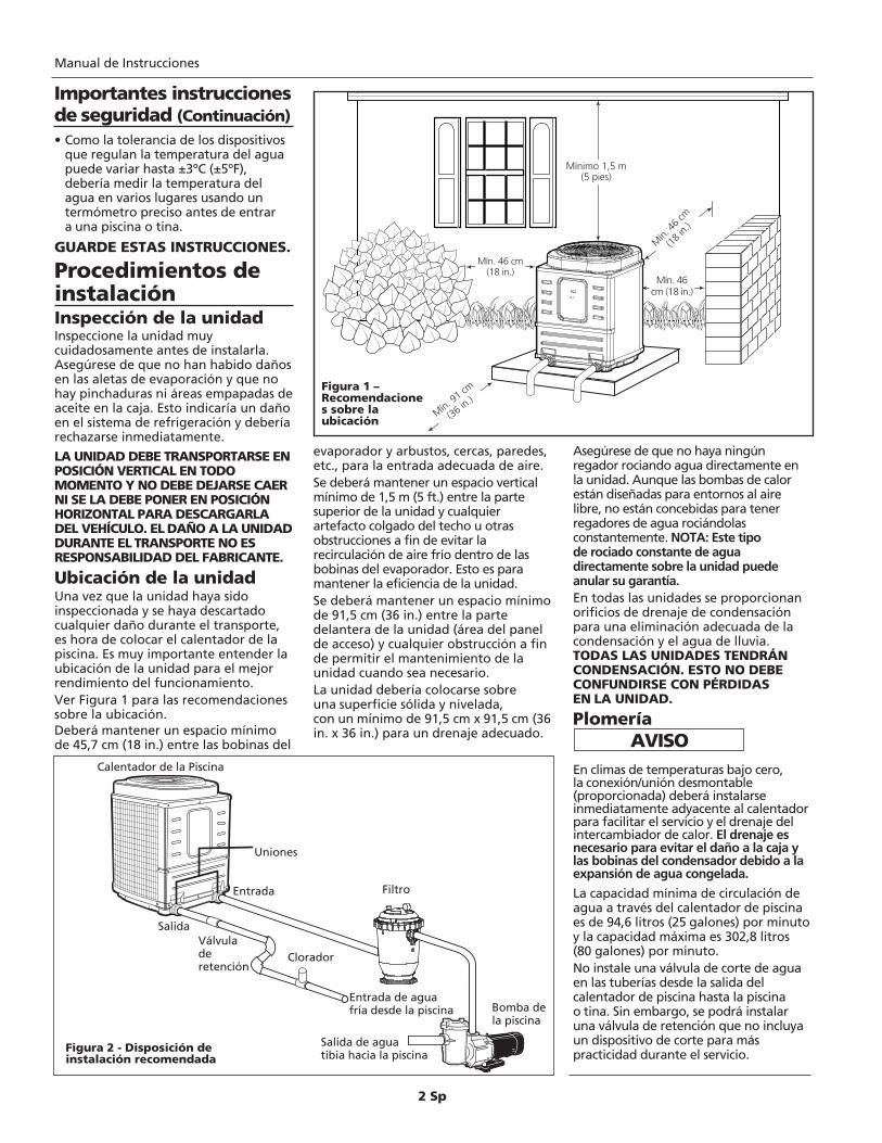
Procedimientos deinstalaciónInspección de la unidadInspeccione la unidad muycuidadosamente antes de instalarla.Asegúrese de que no han habido dañosen las aletas de evaporación y que nohay pinchaduras ni áreas empapadas deaceite en la caja. Esto indicaría un dañoen el sistema de refrigeración y deberíarechazarse inmediatamente.
LA UNIDAD DEBE TRANSPORTARSE ENPOSICIÓN VERTICAL EN TODOMOMENTO Y NO DEBE DEJARSE CAERNI SE LA DEBE PONER EN POSICIÓNHORIZONTAL PARA DESCARGARLADEL VEHÍCULO. EL DAÑO A LA UNIDADDURANTE EL TRANSPORTE NO ESRESPONSABILIDAD DEL FABRICANTE.
Ubicación de la unidadUna vez que la unidad haya sidoinspeccionada y se haya descartadocualquier daño durante el transporte,es hora de colocar el calentador de lapiscina. Es muy importante entender laubicación de la unidad para el mejorrendimiento del funcionamiento. Ver Figura 1 para las recomendacionessobre la ubicación.Deberá mantener un espacio mínimode 45,7 cm (18 in.) entre las bobinas del
evaporador y arbustos, cercas, paredes,etc., para la entrada adecuada de aire.Se deberá mantener un espacio verticalmínimo de 1,5 m (5 ft.) entre la partesuperior de la unidad y cualquierartefacto colgado del techo u otrasobstrucciones a fin de evitar larecirculación de aire frío dentro de lasbobinas del evaporador. Esto es paramantener la eficiencia de la unidad.Se deberá mantener un espacio mínimode 91,5 cm (36 in.) entre la partedelantera de la unidad (área del panelde acceso) y cualquier obstrucción a finde permitir el mantenimiento de launidad cuando sea necesario.La unidad debería colocarse sobreuna superficie sólida y nivelada,con un mínimo de 91,5 cm x 91,5 cm (36in. x 36 in.) para un drenaje adecuado.
Asegúrese de que no haya ningúnregador rociando agua directamente enla unidad. Aunque las bombas de calorestán diseñadas para entornos al airelibre, no están concebidas para tenerregadores de agua rociándolasconstantemente. NOTA: Este tipode rociado constante de aguadirectamente sobre la unidad puedeanular su garantía.En todas las unidades se proporcionanorificios de drenaje de condensaciónpara una eliminación adecuada de lacondensación y el agua de lluvia.TODAS LAS UNIDADES TENDRÁNCONDENSACIÓN. ESTO NO DEBECONFUNDIRSE CON PÉRDIDASEN LA UNIDAD.
Plomería
En climas de temperaturas bajo cero,la conexión/unión desmontable(proporcionada) deberá instalarseinmediatamente adyacente al calentadorpara facilitar el servicio y el drenaje delintercambiador de calor. El drenaje esnecesario para evitar el daño a la caja ylas bobinas del condensador debido a laexpansión de agua congelada.
La capacidad mínima de circulación deagua a través del calentador de piscinaes de 94,6 litros (25 galones) por minutoy la capacidad máxima es 302,8 litros(80 galones) por minuto.No instale una válvula de corte de aguaen las tuberías desde la salida delcalentador de piscina hasta la piscinao tina. Sin embargo, se podrá instalaruna válvula de retención que no incluyaun dispositivo de corte para máspracticidad durante el servicio.
5 feet (minimum)
18“ min
18“ min
18“ min
36” clearance
Mínimo 1,5 m(5 pies)
Mín.
46
cm
(18
in.)
Mín. 46 cm(18 in.)
Mín. 91 cm
(36 in.)
Mín. 46cm (18 in.)
Figura 1 –Recomendaciones sobre laubicación
Figura 2 - Disposición deinstalación recomendada
Calentador de la Piscina
Uniones
Filtro
Bomba dela piscina
Clorador
Entrada de aguafría desde la piscina
Salida de aguatibia hacia la piscina
Entrada
SalidaVálvuladeretención
Manual de Instrucciones
Importantes instruccionesde seguridad (Continuación)
3 Sp
Se recomienda una válvula de retencióno Hartford Loop entre la unidad y unclorador. El clorador debe estar situadoabajo de la bomba de calor. El no hacerlopodría anular la garantía.Si dispone de un sistema de limpiezaintegrado, por favor tome nota de losrequisitos especiales de plomería parapoder operar la unidad con eficacia.La Figura 2 muestra la disposición deinstalación recomendada.
Funcionamientobásico de la bombade calorConexiones eléctricas
Todo el cableado e instalacioneseléctricas deberán ser realizados por unelectricista calificado. Las instalacionesdeberán realizarse conforme a loscódigos locales y nacionales.
Un cableado inadecuado provocarádaños por sobrecalentamiento,cortocircuitos e incendio.Todas las unidades están equipadas con undiagrama esquemático del cableadoeléctrico dentro del panel eléctrico. Si estono está, póngase en contacto con la fábricaal 1-877-278-2797 para obtener uno. Todas las unidades deberán cablearsepara 230 VCA, monofásica. Estasunidades requieren un disyuntordedicado de 50 amp o un fusible detiempo de retardo.El calentador de piscinas deberáinstalarse conforme al Artículo 680 delCódigo Eléctrico Nacional (NEC), el NFPA70, y cumplir con todos los requisitos detodos los códigos locales con jurisdicción.
Controles electrónicosde temperatura Todas lasunidades excepto PRO1100
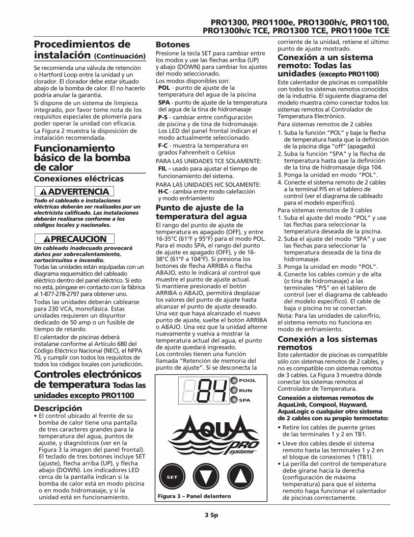
Descripción• El control ubicado al frente de su
bomba de calor tiene una pantallade tres caracteres grandes para latemperatura del agua, puntos deajuste, y diagnósticos (ver en laFigura 3 la imagen del panel frontal).El teclado de tres botones incluye SET(ajuste), flecha arriba (UP), y flechaabajo (DOWN). Los indicadores LEDcerca de la pantalla indican si labomba de calor está en modo piscinao en modo hidromasaje, y si launidad está en funcionamiento.
BotonesPresione la tecla SET para cambiar entrelos modos y use las flechas arriba (UP)y abajo (DOWN) para cambiar los ajustesdel modo seleccionado. Los modos disponibles son:POL - punto de ajuste de latemperatura del agua de la piscinaSPA - punto de ajuste de la temperaturadel agua de la tina de hidromasajeP-S - cambiar entre configuraciónde piscina y de tina de hidromasaje.Los LED del panel frontal indican elmodo actualmente seleccionado.F-C - muestra la temperatura engrados Fahrenheit o Celsius
PARA LAS UNIDADES TCE SOLAMENTE:FIL – usado para ajustar el tiempo defuncionamiento del sistema.
PARA LAS UNIDADES H/C SOLAMENTE:H-C - cambia entre modo calefaccióny modo enfriamiento
Punto de ajuste de latemperatura del aguaEl rango del punto de ajuste detemperatura es apagado (OFF), y entre16-35°C (61°F y 95°F) para el modo POL.Para el modo SPA, el rango del puntode ajuste es apagado (OFF), y de 16-38°C (61°F a 104°F). Si presiona losbotones de flecha ARRIBA o flechaABAJO, esto le indicará al control quemuestre el punto de ajuste actual.Si mantiene presionado el botónARRIBA o ABAJO, permitirá desplazarlos valores del punto de ajuste hastaalcanzar el punto de ajuste deseado.Una vez que haya alcanzado el nuevopunto de ajuste, suelte el botón ARRIBAo ABAJO. Una vez que la unidad alternenuevamente y vuelva a mostrar latemperatura actual del agua, el puntode ajuste quedará ingresado.Los controles tienen una funciónllamada “Retención de memoria delpunto de ajuste”. Si se desconecta la
corriente de la unidad, retiene el últimopunto de ajuste mostrado.
Conexión a un sistemaremoto: Todas lasunidades (excepto PRO1100)Este calentador de piscinas es compatiblecon todos los sistemas remotos conocidosde la industria. El siguiente diagrama delmodelo muestra cómo conectar todos lossistemas remotos al Controlador deTemperatura Electrónico. Para sistemas remotos de 2 cables1. Suba la función “POL” y baje la flecha
de temperatura hasta que la definiciónde la piscina diga “off” (apagado)
2. Suba la función “SPA” y la flecha detemperatura hasta que la definiciónde la tina de hidromasaje diga 104.
3. Ponga la unidad en modo “POL”.4. Conecte el sistema remoto de 2 cables
a la terminal P/S en el tablero decontrol (ver el diagrama de cableadopara el modelo específico).
Para sistemas remotos de 3 cables1. Suba el ajuste del modo “POL” y use
las flechas para seleccionar latemperatura deseada de la piscina.
2. Suba el ajuste del modo “SPA” y uselas flechas para seleccionar latemperatura deseada de la tina dehidromasaje.
3. Ponga la unidad en modo “POL”.4. Conecte los cables común y de alta
(o tina de hidromasaje) a lasterminales “P/S” en el tablero decontrol (ver el diagrama de cableadodel modelo específico). El cable debaja o piscina no se conectan.
Nota: Para las unidades de calor/frío,el sistema remoto no funciona enmodo de enfriamiento.
Conexión a los sistemasremotosEste calentador de piscinas es compatiblesólo con sistemas remotos de 2 cables, yno es compatible con sistemas remotosde 3 cables. La Figura 3 muestra dóndeconectar los sistemas remotos alControlador de Temperatura.
Conexión a sistemas remotos deAquaLink, Compool, Hayward,AquaLogic o cualquier otro sistemade 2 cables con su propio termostato:
• Retire los cables de puente grisesde las terminales 1 y 2 en TB1.
• Lleve dos cables desde el sistemaremoto hasta las terminales 1 y 2 enel bloque de conexiones 1 (TB1).
• La perilla del control de temperaturadebe girarse hacia la derecha(configuración de máximatemperatura) para que el sistemaremoto haga funcionar el calentadorde piscinas correctamente.
Procedimientos deinstalación (Continuación)
PRO1300, PRO1100e, PRO1300h/c, PRO1100,PRO1300h/c TCE, PRO1300 TCE, PRO1100e TCE
Figura 3 – Panel delantero
4 Sp
Bloqueo por altatemperatura (todas lasunidades excepto PRO1100)Su bomba de calor incluye una funciónespecial de “bloqueo” de los ajustes dealta temperatura. Esto elimina lanecesidad de un dispositivo de bloqueodel termostato. Esto impide quepersonas no autorizadas regulenla bomba de calor por encima delos límites deseados. Para activaresta función, por favor llame a AquaPRO® Systems al 877-AQUA-SYS(877-278-2797) durante las horas detrabajo, de 8 AM a 5 PM EDT de lunesa viernes, y con gusto le asistiremos paraactivar esta función.
Controles de temp.manualesDescripción• El Control de temperatura manual
está diseñado para regular latemperatura del agua de la piscina yde la tina de hidromasaje.
• Hay dos luces indicadoras en el panelde control para mostrar el estadoactual de la unidad.
• La perilla del termostato puedeajustarse para mantener latemperatura deseada del agua.
Luces indicadoras• Hay dos luces indicadoras en el panel
delantero que muestran el estado dela unidad. La luz VERDE indica que lacorriente de la unidad está activa. Laluz ROJA indica que la unidad está enmodo de calefacción.
• La luz ROJA puede encenderse antesde que comience a funcionar elcalentador. La luz ROJA se encenderácuando la perilla del termostato seconfigure a la temperatura del aguao por encima de ella.
• La unidad tiene un tiempo de retardoincorporado. Cada vez que la unidadse apaga hay un tiempo de retardo decinco minutos hasta que la unidadpueda reiniciarse. Puede que la luz deCALOR se encienda durante este ciclode retardo. No gire la perilla deltermostato durante este tiempo deretardo. Si gira la perilla durante esteciclo se podría reiniciar el tiempo deretardo, provocando que la unidaddemore cinco minutos adicionalesantes de comenzar a funcionar.
Punto de ajuste de latemperatura del agua• El rango del punto de ajuste de la
temperatura es de 7ºC a 42ºC (45ºF a107ºF). Si gira la perilla deltermostato hacia la derecha,aumentará el punto de ajuste de latemperatura, mientras que si gira laperilla hacia la izquierda, disminuiráel punto de ajuste de la temperatura.
• Se puede colocar un termómetroflotante en la piscina o la tina dehidromasaje para controlar latemperatura del agua.
• Para calibrar inicialmente eltermostato al punto de ajustedeseado, gire la perilla deltermostato hacia la derecha, hasta eltope. La unidad se encenderáy comenzará a calentar después deun posible tiempo de retardo decinco minutos. Permita que la unidadfuncione hasta que el agua de lapiscina o de la tina de hidromasajealcance la temperatura deseada. Girelentamente la perilla del termostatohacia la izquierda hasta que launidad se apague. La unidadmantendrá ahora esta temperaturadel agua, siempre que la bomba decirculación esté funcionando.
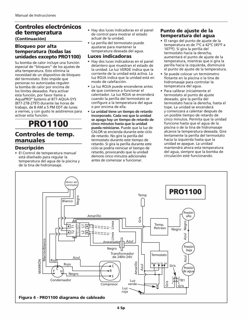
Motor del ventilador
Blanco
Condensador
Neg
ro
Amarillo
T2 T
1
MA
RR
ÓN M
arró
n/b
lan
co
Rojo
Negro
CF H
Rojo
Azul
Compresor
CR
S
Inte
rrup
tor
auto
mát
icoL2
L1
Lín
ea
Lín
ea
Anaranjado Azul
Negro
Transformador de 240V-24V
Gri
s
Temp
Temp.Retraso Negro N
egro
Azu
l
Presión alta
Presión baja
Presión de agua
Azu
l
Am
arill
o
Azu
l
Termostato
Nuet Cal. En. Sal.
Luz roja
Luz verde
Gris
GrisGri
s
43
21TB1
Figura 4 - PRO1100 diagrama de cableado
PRO1100
Manual de Instrucciones
Controles electrónicosde temperatura(Continuación)
PRO1100
5 Sp
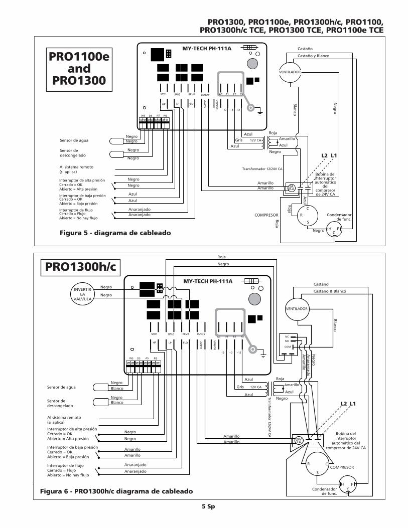
Figura 5 - diagrama de cableado
Sensor de agua
Sensor dedescongelado
Interruptor de alta presiónCerrado = OKAbierto = Alta presión
Interruptor de baja presiónCerrado = OKAbierto = Baja presión
Interruptor de flujoCerrado = FlujoAbierto = No hay flujo
MY-TECH PH-111A Castaño
Castaño y Blanco
VENTILADOR
SPR1 SPR2 REVR JANDY
HP LP FLO
COM
P
BOM
BA
12 ~8 ~12
AC F1 F2 F3
WS DS AS P/S
Neg
ro
Negro
Negro
Azul
Anaranjado
Azul
Anaranjado
AzulGris 12V CA
Azul
Roja
Azul
Transformador 12/24V CA
Negro
AmarilloAmarillo 24
VCA
COMPRESOR R
S
C
Bobina delinterruptorautomático
delcompresorde 24V CA
Condensadorde func.
L1L2
Negro
Negro
Amarillo
Negro
Ro
ja
HC
F
Ro
ja
Azu
l
Negro
Negro
Blan
co
Al sistema remoto(si aplica)
PRO1100eand
PRO1300
PRO1300, PRO1100e, PRO1300h/c, PRO1100,PRO1300h/c TCE, PRO1300 TCE, PRO1100e TCE
Figura 6 - PRO1300h/c diagrama de cableado
Sensor de agua
Sensor dedescongelado
Interruptor de alta presiónCerrado = OKAbierto = Alta presión
Interruptor de baja presiónCerrado = OKAbierto = Baja presión
Interruptor de flujoCerrado = FlujoAbierto = No hay flujo
Roja
Negro
MY-TECH PH-111ACastaño
Castaño & Blanco
VENTILADOR
SPR1 SPR2 REVR JANDY
HP LP FLO
COM
P
BOM
BA
12 ~0 ~12
AC F1 F2 F3
WS DS AS P/S
Blanco
Blanco
Negro
Negro
Amarillo
Anaranjado
Amarillo
Anaranjado
Azul
Gris 12V CA
Azul
Roja
Azul
Transfo
rmad
or 12/24V
CA
Negro
Amarillo
AmarilloAmarillo
24VCA
COMPRESORR
S
C
Bobina delinterruptor
automático delcompresor de 24V CA
Condensadorde func.
L1L2
INVERTIRLA
VÁLVULA
Negro
Negro
NC
NO
COM
Negro
Negro
Blan
co
Am
arillo
Neg
roA
naran
jado
HC
F
Al sistema remoto(si aplica)
PRO1300h/c
6 Sp
Controles electrónicosde temperaturaCómo alternar entre Modode calefacción y Modo deenfriamientoLa unidad estará definida por defecto enel modo de calefacción. Si desea el modode enfriamiento, presione el botón SET(configuración) hasta que se muestre lapantalla H-C. Luego presione los botonesde las flechas hasta que aparezca “COL”en la pantalla. Esto hace que la unidad secoloque en modo de enfriamiento. Elpunto de ajuste de la temperatura delagua será la temperatura del agua a laque la unidad está enfriando el agua.Cuando la unidad está en el modo deenfriamiento, la pantalla mostraráintermitentemente la temperaturaactual del agua y “COL” para recordar alusuario que el modo de enfriamientoestá activado.
Ciclo de descongelaciónSu unidad AquaPRO® h/c puedemantener su piscina tibia en temperaturasmuy frías. La mayoría de los calentadoresde piscinas no funcionan por encima delos 10°C (50°F). Su unidad h/c funcionahasta 3°C (38°F) empleando el ciclo dedescongelación. Lo hace automáticamenteregistrando la temperatura delrefrigerante e invirtiendo elfuncionamiento por 2 minutos paradescongelar la bobina del evaporador yreiniciar la función de calefacción.
Selección de lafuncionalidad dela unidadEsta unidad puede actuar comoLimitador del Temporizador o comoEliminador del Temporizador. Si yadispone de un temporizador en supiscina y desea mantener sufuncionamiento normal con la ventajaadicional del limitador del temporizadorpara la bomba de calor – sírvase leer lasección Operación TCO (con Limitacióndel Temporizador). Si no dispone de untemporizador para su sistema de piscina– sírvase leer la sección Operación TCE(con Eliminación del Temporizador).
Operación conEliminación delTemporizador (TCE)Por favor sírvase leer cuidadosamentelas funciones de esta característica.
Todo el cableado e instalaciones eléctricasdeberán ser realizados por un electricistacalificado. La instalación deberá realizarseconforme a los códigos locales ynacionales.Para que la función TCE pueda actuar, subomba de piscina debe ser conectada ala bomba de calor. Ver en la Figura 7 laconexión para la función TCE.• Esta unidad viene con la función
TCE preinstalada de fábrica,pero ajustada a la posición “off”(apagada) en el modo “FIL”.Usted tiene que definir las horasdel tiempo de funcionamientopara el sistema de bomba y filtro.Ver a continuación “activar yajustar el tiempo defuncionamiento del sistema”.
•La función de TCE se realiza pormedio de una secuencia de 6 períodosde tiempo en las 24 horas. Ustedselecciona las horas para el tiempode funcionamiento requerido parala bomba del filtro, y el calentador seencarga del resto. Lo hace dividiendoel tiempo de funcionamiento delsistema en 6 períodos iguales,encendiendo la bomba por 1/6 deltiempo de funcionamiento indicadoy apagándola por el tiempo restante,a menos que se requiera caloradicional. El calentador pondrá enfuncionamiento el sistema a diarioy por el tiempo de funcionamientoque usted ha seleccionado.La secuencia de tiempo empieza almomento de arranque inicial.
• Si la piscina se encuentra a latemperatura de funcionamientodeseada o por encima de la misma,el calentador pondrá enfuncionamiento el sistema por lashoras deseadas cada día y distribuiráel tiempo igualmente en 6 períodos.Esto permite un mejorfuncionamiento del filtro y le permiteal calentador de ajustar latemperatura del agua 6 veces al día.
• Si la piscina necesita calor, elcalentador sigue operando elsistema hasta que alcance latemperatura deseada. Si el tiempode funcionamiento excede el tiempode funcionamiento de un período,el tiempo en exceso viene sustraído
del(los) tiempo(s) de funcionamientosiguiente(s). Note que en días fríos o demucho viento, es posible que la unidadfuncione por largo tiempo, paraalcanzar y mantener la temperaturadeseada de la piscina. Vea por favor lasección “aplicación” sobre “cubiertaspara la piscina” para ayudar amantener la temperatura de la piscina.
• La función de temporizador incorporadaen el TCE hace funcionar siempre labomba de calor por 15 minutos cada 4horas, para determinar si se necesita máscalor para mantener la temperaturadeseada de la piscina – aún si todo eltiempo de funcionamiento disponibleha sido usado en ciclos anteriores. Estoproporciona dos ventajas adicionales.Las piscinas pierden la mayoría del calordurante la noche si se dejan destapadas;sin embargo, puesto que la unidadchequea y añade calor cuando esnecesario, esto impide que se produzcanlargos períodos de recuperación, cuandose compara con unidades que no tienenTCE. La otra ventaja es que algunosestados y empresas de abastecimientode electricidad ofrecen descuentos parael uso del servicio eléctrico fuera de lashoras pico. Por cualquier pregunta,sírvase contactar su empresa de servicioeléctrico.
• Ejemplo de funcionamiento TCE –usted requiere que el sistemafuncione por 12 horas para satisfacerlas necesidades de filtración de lapiscina. Esto quiere decir que paracada uno de los períodos de 6 horas,el calentador hace funcionar elsistema por 2 horas y luego lo apagapor 2 horas. Si el sistema necesitafuncionar por 3 horas en uno de losperíodos para alcanzar la temperaturadeseada de la piscina, el períodosiguiente será de 1 hora encendidoy 3 horas apagado, a menos queno se requiera más calefacción.El ciclo continúa por 6 períodosy reinicia al final de cada 24 horas.Si necesita más explicaciones sobre elfuncionamiento de esta característica,llame por favor a AquaPRO® Systems, al 1-877-AQUA-SYS (1-877-278-2797).
Puesta en marcha y ajuste deltiempo de funcionamiento –Operación TCE•Para el ajuste del tiempo de
funcionamiento, oprima la tecla“SET” repetidamente hasta queaparezca “FIL”. Luego, por medio delas flechas arriba y abajo, puedeseleccionar cuántas horas en total pordía quiere que el sistema trabaje, paralas necesidades de la bomba y defiltración. El rango de horas es de
PRO1300h/c
PRO1100e TCEand PRO1300 TCE
Manual de Instrucciones
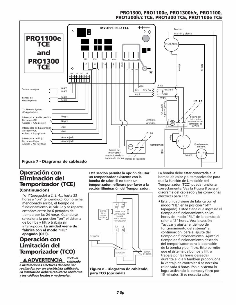
7 Sp
Esta sección permite la opción de usarun temporizador existente con labomba de calor. Si no tiene untemporizador, refiérase por favor a lasección Eliminación del Temporizador.
La bomba debe estar conectada a labomba de calor y al temporizador paraque la función de Limitación delTemporizador (TCO) pueda funcionarcorrectamente. Vea la Figura 8 para eldiagrama del cableado y las conexioneseléctricas para TCO.
•Esta unidad viene de fábrica con elmodo “FIL” en la posición “off”(apagado). Usted tiene que ingresar eltiempo de funcionamiento en lashoras del modo “FIL” de la bomba decalor a “2” horas. Vea la sección“activar y ajustar el tiempo defuncionamiento del sistema” acontinuación, para el ajuste deltiempo de funcionamiento. Ajuste eltiempo de funcionamiento deseadodel temporizador para la operaciónde la bomba y del filtro. Esto permiteque el sistema de bomba y filtrotrabaje por las horas deseadasdurante el día y también proporcionala ventaja de controlar si se necesitacalor cada 4 horas. Eso el sistema lologra activando la bomba y filtro por15 minutos. Si se necesita calor,
Operación conEliminación delTemporizador (TCE)(Continuación)
Figura 7 - Diagrama de cableado
MY-TECH PH-111A Marrón
Marrón y blanco
SPR1 SPR2 REVR JANDY
HP LP FLO
COM
P
BOM
BA
12 ~8 ~12
AC F1 F2 F3
WS DS AS P/S
Negro
Negro
Azul
Anaranjado
Azul
Anaranjado
Azul
Gris 12V CA
Azul
Rojo
Azul
Transfo
rmad
or
12/24V C
A
Negro
AmarilloAmarillo 24V
CA
COMPRESOR
R
S
C
Bobina delinterruptor
automático delcompresor de
24V CA
Condensadorde func.
L1L2
Negro
Negro
Amarillo
Neg
ro
Negro
Ro
jo HC
F
Ro
jo
Axu
l
VENTILADOR
Negro
Negro
Blan
co
24V CA
Bobina delinterruptor
automático de labomba de piscina
L4
Bomba de la piscina
L3
To Remote System(If Applicable)
Interruptor de alta presiónCerrado = OKAbierto = Alta presión
Interruptor de baja presiónCerrado = OKAbierto = Baja presión
Interruptor de flujoCerrado = FlujoAbierto = No hay flujo
Sensor de agua
Sensor dedescongelado
PRO1300, PRO1100e, PRO1300h/c, PRO1100,PRO1300h/c TCE, PRO1300 TCE, PRO1100e TCE
BREAKER
TIME CLOCK
FILTER PUMP
CONTACTOR FOR THE
TIME CLOCK
OVERRIDE
INSIDE HEAT PUMP
T2 T1
L3 L4
DENTRODE LA
BOMBADE CALOR
INTERRUPTORAUTOMÁTICO
PARA LALIMITACIÓN DELTEMPORIZADOR
TEMPORIZADOR BOMBADEL FILTRO
DISYUNTOR
Figura 8 - Diagrama de cableadopara TCO (opcional)
PRO1100eTCEand
PRO1300TCE
“off”(apagado) a 2, 3, 4... hasta 23horas a “on” (encendido). Como se hamencionado arriba, el tiempo defuncionamiento se calcula y se reparteentonces entre los 6 períodos detiempo por las 24 horas. Cuando seselecciona la posición “on” el sistemade bomba y filtro trabaja sininterrupción. La unidad viene defábrica con el modo “FIL”apagado (OFF).
Operación conLimitación delTemporizador (TCO)
Todo el cableado
e instalaciones eléctricas deberán serrealizados por un electricista calificado.La instalación deberá realizarse conformea los códigos locales y nacionales.
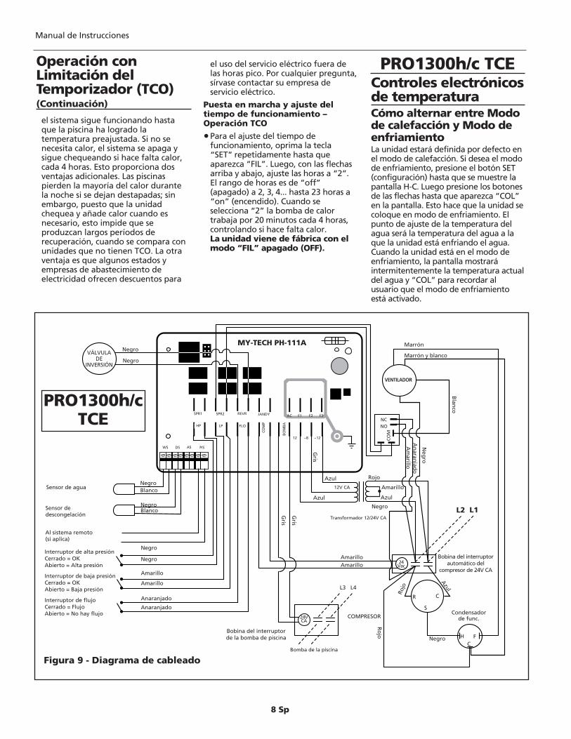
8 Sp
el sistema sigue funcionando hastaque la piscina ha logrado latemperatura preajustada. Si no senecesita calor, el sistema se apaga ysigue chequeando si hace falta calor,cada 4 horas. Esto proporciona dosventajas adicionales. Las piscinaspierden la mayoría del calor durantela noche si se dejan destapadas; sinembargo, puesto que la unidadchequea y añade calor cuando esnecesario, esto impide que seproduzcan largos períodos derecuperación, cuando se compara conunidades que no tienen TCO. La otraventaja es que algunos estados yempresas de abastecimiento deelectricidad ofrecen descuentos para
el uso del servicio eléctrico fuera delas horas pico. Por cualquier pregunta,sírvase contactar su empresa deservicio eléctrico.
Puesta en marcha y ajuste deltiempo de funcionamiento –Operación TCO
•Para el ajuste del tiempo defuncionamiento, oprima la tecla“SET” repetidamente hasta queaparezca “FIL”. Luego, con las flechasarriba y abajo, ajuste las horas a “2”.El rango de horas es de “off”(apagado) a 2, 3, 4... hasta 23 horas a“on” (encendido). Cuando seselecciona “2” la bomba de calortrabaja por 20 minutos cada 4 horas,controlando si hace falta calor.La unidad viene de fábrica con elmodo “FIL” apagado (OFF).
Controles electrónicosde temperaturaCómo alternar entre Modode calefacción y Modo deenfriamientoLa unidad estará definida por defecto enel modo de calefacción. Si desea el modode enfriamiento, presione el botón SET(configuración) hasta que se muestre lapantalla H-C. Luego presione los botonesde las flechas hasta que aparezca “COL”en la pantalla. Esto hace que la unidad secoloque en modo de enfriamiento. Elpunto de ajuste de la temperatura delagua será la temperatura del agua a laque la unidad está enfriando el agua.Cuando la unidad está en el modo deenfriamiento, la pantalla mostraráintermitentemente la temperatura actualdel agua y “COL” para recordar alusuario que el modo de enfriamientoestá activado.
PRO1300h/c TCE
Sensor de agua
Sensor dedescongelación
Interruptor de alta presiónCerrado = OKAbierto = Alta presión
Interruptor de baja presiónCerrado = OKAbierto = Baja presión
Interruptor de flujoCerrado = FlujoAbierto = No hay flujo
MY-TECH PH-111A Marrón
Marrón y blanco
SPR1 SPR2 REVR JANDY
HP LP FLO
COM
P
BOM
BA
12 ~8 ~12
AC F1 F2 F3
WS DS AS P/S
Negro
Negro
Amarillo
Anaranjado
Amarillo
Anaranjado
Azul
12V CA
Azul
Rojo
Azul
Transformador 12/24V CA
Negro
AmarilloAmarillo 24
Vac
COMPRESOR
R
S
C
Bobina del interruptorautomático del
compresor de 24V CA
Condensadorde func.
L1L2
Negro
Negro
Amarillo
Neg
ro
Negro
Ro
jo HC
F
Rojo
Azul
VENTILADOR
Blanco
Blanco
Blan
co
Bobina del interruptorde la bomba de piscina
L4
Bomba de la piscina
L3
Gris
Gris
24VCA
Gris
An
aranjad
oA
marillo
NCNO
CO
M
Negro
NegroVÁLVULA
DEINVERSIÓN
Figura 9 - Diagrama de cableado
Al sistema remoto (si aplica)
Manual de Instrucciones
PRO1300h/cTCE
Operación conLimitación delTemporizador (TCO)(Continuación)
9 Sp
Ciclo de descongelaciónSu unidad AquaPRO® h/c puede mantenersu piscina tibia en temperaturas muy frías.La mayoría de los calentadores de piscinasno funcionan por encima de los 10°C(50°F). Su unidad h/c funciona hasta 3°C(38°F) empleando el “ciclo dedescongelación”. Lo haceautomáticamente registrando latemperatura del refrigerante e invirtiendoel funcionamiento por 2 minutos paradescongelar la bobina del evaporador yreiniciar la función de calefacción.
Selección de lafuncionalidad de launidadEsta unidad puede actuar comoLimitador del Temporizador o comoEliminador del Temporizador. Si yadispone de un temporizador para supiscina y desea mantener sufuncionamiento normal con la ventajaadicional del limitador del temporizadorpara la bomba de calor – sírvase leer lasección Operación TCO (Limitación delTemporizador). Si no dispone de untemporizador para su sistema de piscina– sírvase leer la sección Operación TCE(Eliminación del Temporizador).
Operación conEliminación delTemporizador (TCE)Por favor sírvase leer cuidadosamente lasfunciones de esta característica.
Todo elcableado e
instalaciones eléctricas deberán serrealizados por un electricista calificado. Lainstalación deberá realizarse conforme alos códigos locales y nacionales.Para que la característica de TCE puedafuncionar, la bomba de la piscina debeestar conectada a la bomba de calor.Vea la Figura 9 para el cableado de lafunción TCE.•Esta unidad viene con la función
TCE preinstalada de fábrica, peroajustada a la posición “off”(apagada) en el modo “FIL”.Usted tiene que definir las horasdel tiempo de funcionamientopara el sistema de bomba y filtro.Ver a continuación “activar yajustar el tiempo defuncionamiento del sistema”.
• La función de TCE se realiza por mediode una secuencia de 6 períodos detiempo en las 24 horas. Ustedselecciona las horas para el tiempo defuncionamiento requerido para labomba del filtro, y el calentador seencarga del resto. Lo hace dividiendoel tiempo de funcionamiento delsistema en 6 períodos iguales,encendiendo la bomba por 1/6 deltiempo de funcionamiento indicado yapagándola por el tiempo restante, amenos que se requiera calor adicional.El calentador pondrá enfuncionamiento el sistema a diario ypor el tiempo de funcionamiento queusted ha seleccionado. La secuencia detiempo empieza al momento dearranque inicial.
• Si la piscina se encuentra a latemperatura de funcionamientodeseada o por encima de la misma, elcalentador pondrá en funcionamientoel sistema por las horas deseadas cadadía y distribuirá el tiempo igualmenteen 6 períodos. Esto permite un mejorfuncionamiento del filtro y le permiteal calentador de ajustar latemperatura del agua 6 veces al día.
• Si la piscina necesita calor, elcalentador sigue operando el sistemahasta que alcance la temperaturadeseada. Si el tiempo defuncionamiento excede el tiempo defuncionamiento de un período, eltiempo en exceso viene sustraído del(los) tiempo(s) de funcionamientosiguiente(s). Note que en días fríos ode mucho viento, es posible que la
unidad funcione por largo tiempo,para alcanzar y mantener latemperatura deseada de la piscina.Vea por favor la sección “aplicación”sobre “cubiertas para la piscina” paraayudar a mantener la temperatura dela piscina.
• La función de temporizadorincorporada en el TCE hace funcionarsiempre la bomba de calor por 15minutos cada 4 horas, paradeterminar si se necesita más calorpara mantener la temperaturadeseada de la piscina – aún si todo eltiempo de funcionamiento disponibleha sido usado en ciclos anteriores.Esto proporciona dos ventajasadicionales. Las piscinas pierden lamayoría del calor durante la noche sise dejan destapadas; sin embargo,puesto que la unidad chequea yañade calor cuando es necesario, estoimpide que se produzcan largosperíodos de recuperación, cuando secompara con unidades que no tienenTCE. La otra ventaja es que algunosestados y empresas de abastecimientode electricidad ofrecen descuentospara el uso del servicio eléctrico fuerade las horas pico. Por cualquierpregunta, sírvase contactar suempresa de servicio eléctrico.
• Ejemplo – usted requiere que elsistema funcione por 12 horas parasatisfacer las necesidades de filtraciónde la piscina. Esto quiere decir quepara cada uno de los períodos de 6horas, el calentador hace funcionar elsistema por 2 horas y luego lo apagapor 2 horas. Si el sistema necesitafuncionar por 3 horas en uno de losperíodos para alcanzar la temperaturadeseada de la piscina, el períodosiguiente será de 1 hora encendido y 3horas apagado, a menos que serequiera más calefacción. El ciclocontinúa por 6 períodos y reinicia alfinal de cada 24 horas. Si necesita másexplicaciones sobre el funcionamientode esta característica, llame por favora AquaPRO® Systems, al 1-877-AQUA-SYS (1-877-278-2797).
Puesta en marcha y ajuste deltiempo de funcionamiento –Operación TCE
•Para el ajuste del tiempo defuncionamiento, oprima la tecla“SET” repetidamente hasta queaparezca “FIL”. Luego, por medio de
Controles electrónicosde temperatura(Continuación)
PRO1300, PRO1100e, PRO1300h/c, PRO1100,PRO1300h/c TCE, PRO1300 TCE, PRO1100e TCE
BREAKER
TIME CLOCK
FILTER PUMP
CONTACTOR FOR THE
TIME CLOCK
OVERRIDE
INSIDE HEAT PUMP
T2 T1
L3 L4
INSIDEHEATPUMP
CONTACTORFOR THE
TIME CLOCKOVERRIDE
TIMECLOCK
FILTERPUMP
BREAKER
Figure 10 - TCO wiring diagram(optional)
10 Sp
las flechas arriba y abajo, puedeseleccionar cuántas horas en total pordía quiere que el sistema trabaje, paralas necesidades de la bomba y defiltración. El rango de horas es de “off”(apagado) a 2, 3, 4... hasta 23 horas a“on” (encendido). Como se hamencionado arriba, el tiempo defuncionamiento se calcula y se reparteentonces entre los 6 períodos de tiempopor las 24 horas. Cuando se selecciona laposición “on” el sistema de bomba yfiltro trabaja sin interrupción. La unidadviene de fábrica con el modo “FIL”apagado (OFF).
Operación conLimitación delTemporizador (TCO)
Todo elcableado e
instalaciones eléctricas deberán serrealizados por un electricista calificado.La instalación deberá realizarse conformea los códigos locales y nacionales.
Esta sección permite la opción de usar untemporizador existente con la bomba decalor. Si no tiene un temporizador,refiérase por favor a la secciónEliminación del Temporizador.La bomba debe estar conectada a labomba de calor y al temporizador paraque la función de Limitación delTemporizador (TCO) pueda funcionarcorrectamente. Vea la Figura 8 para eldiagrama del cableado y las conexioneseléctricas para TCO.
•Esta unidad viene de fábrica con elmodo “FIL” en la posición “off”(apagado). Usted tiene que ingresarel tiempo de funcionamiento en lashoras del modo “FIL” de la bomba decalor a “2” horas. Vea la sección“activar y ajustar el tiempo defuncionamiento del sistema” acontinuación, para el ajuste deltiempo de funcionamiento. Ajuste eltiempo de funcionamiento deseadodel temporizador para la operaciónde la bomba y del filtro. Esto permiteque el sistema de bomba y filtrotrabaje por las horas deseadasdurante el día y también proporcionala ventaja de controlar si se necesita
calor cada 4 horas. Eso lo lograactivando el sistema de bomba yfiltro por 15 minutos. Si se necesitacalor, sigue funcionando hasta que lapiscina ha logrado la temperaturapreajustada. Si no se necesita calor, elsistema se apaga y sigue chequeandosi hace falta calor, cada 4 horas. Estoproporciona dos ventajas adicionales.Las piscinas pierden la mayoría delcalor durante la noche si se dejandestapadas; sin embargo, puesto quela unidad chequea y añade calorcuando es necesario, esto impide quese produzcan largos períodos derecuperación, cuando se compara conunidades que no tienen TCO. La otraventaja es que algunos estados yempresas de abastecimiento deelectricidad ofrecen descuentos parael uso del servicio eléctrico fuera delas horas pico. Por cualquierpregunta, sírvase contactar suempresa de servicio eléctrico.
Puesta en marcha y ajuste deltiempo de funcionamiento –Operación TCO
•Para el ajuste del tiempo defuncionamiento, oprima la tecla“SET” repetidamente hasta queaparezca “FIL”. Luego, con las flechasarriba y abajo, ajuste las horas a “2”.El rango de horas es de “off”(apagado) a 2, 3, 4... hasta 23 horasa “on” (encendido). Cuando seselecciona “2” la bomba de calortrabaja por 20 minutos cada 4 horas,controlando si hace falta calor. Launidad viene de fábrica con elmodo “FIL” apagado (OFF).
Pautas de aplicación(todos los modelos)MantenimientoTodas las bombas de calor estándiseñadas para uso en espaciosexteriores. Sin embargo, se necesitacierto mantenimiento para mantenertoda la vida útil del calentador y esnecesario para mantener su garantía. Sedebería programar el mantenimientoanual para asegurarse de que se eliminela arena o los residuos del interior delcalentador. También es imprescindibleque enjuague las bobinas mensualmente,con agua a baja presión para mantenerla base de la unidad sin residuos. No useuna lavadora de alta presión. Esto puedecausar daño a las bobinas de suevaporador y anulará su garantía. Se
recomienda que un especialistalicenciado en acondicionamiento de airerealice el mantenimiento anualprogramado de su calentador.
Si decide enjuagar
las bobinas del evaporador usted mismo,desconecte la corriente de todo el equipoantes de enjuagarlo. Esto debe hacerse afin de evitar un posible choque eléctrico.
CondensaciónTodos las bombas de calor para piscinastendrán condensación. Es típico tenertanto como 23 l a 31 litros (6 a 8galones) de condensación o de agua porhora, durante un día cálido y húmedo.No confunda esto con una pérdida.
Si no está seguro si el agua es unapérdida o es condensación, hay dosformas de verificar esto. Primero, useuna tira de prueba para piscinas para versi hay cloro o bromo en el agua. Si loshay, póngase en contacto con la fábricapara solicitar un servicio. En segundolugar, puede apagar el calentador, dejarla bomba del filtro funcionando y ver siel agua deja de correr. Si no ve másagua, entonces el agua que habíaoriginalmente era condensación.
Cubiertas para piscinasSe ha comprobado que las cubiertaspara piscinas reducen en gran medida lapérdida de calor en la piscina yahorrarán un máximo de 50% a 60% ensus facturas de calefacción. Durante elcomienzo de la temporada de veranoy al final de la misma, si no se usa unacubierta para piscinas, puede que elcalentador no pueda mantener latemperatura que usted desea sin eluso de la cubierta.
Cerramientos detemporadaAl final de la temporada de veranopuede tener condiciones climáticas decongelamiento. Las uniones (incluidas)deben desconectarse para drenar todael agua de las tuberías. El no hacer estopodría provocar que el intercambiadorde calor se expandiera y se quebrara.Esto anulará su garantía.
Si vive en una región que no tienecondiciones climáticas decongelamiento pero está sujeto alargos períodos sin uso, permita que elsistema de filtración continúe pasandoagua a través del calentador. O puededrenar toda el agua de la unidad.
Manual de Instrucciones
Operación conEliminación delTemporizador (TCE)(Continuación)
11 Sp
Aberturas de la piscinaSi al final de la temporada anteriorusted desconectó las uniones,asegúrese de conectarlas antes deencender el sistema de filtrado. Unavez que se haya limpiado la piscina y sehaya comprobado que la unidad notiene pérdidas, conecte la corriente delcalentador y configure el termostatoa la temperatura deseada. Nota: Podría llevar hasta tres díasalcanzar la temperatura deseadadurante el comienzo de la temporadade verano. Sin una cubierta parapiscinas, podría llevar aún más tiempoe incluso podría suceder que no sealcanzara la temperatura deseada hastaun momento posterior en la temporada.
Condiciones climáticasLas condiciones climáticas juegan unpapel esencial en el funcionamiento delcalentador. Las temperaturas exterioresbajas, los vientos fuertes, la humedadrelativa baja y una gran cantidad desombra en la piscina tendrán un efectoen el tiempo que demore en calentar lapiscina, y en el tiempo que se necesitarápara mantener la temperatura deseada.Una vez que la temperatura ambienteexterior baje por debajo de los 10ºC(50ºF) [3°C (38°F) para las unidades h/c],es posible que el calentador no funcione.
Guía de diagnósticoy resolución deproblemas Si el calentador no está funcionandodurante el encendido inicial, verifiquepara ver si se ha instalado correctamente,según este manual del propietario.Asegúrese de que el disyuntor se hayamedido correctamente. Las siguientesson condiciones a verificar antes dellamar a AquaPRO® Systems para solicitarun servicio:
DiagnósticosTodos los modelos (excepto PRO1100)
La pantalla ubicada en la bomba de calortiene códigos de diagnóstico, queayudan a explicar cualquier motivo porel que el calentador no esté funcionandocorrectamente. Los siguientes son loscódigos de diagnóstico y los motivos porlos que aparecen:
FLO: Este código significa “Interruptorde presión” o interruptor de la presióndel agua. Esto significa que no hay flujode agua suficiente para activar elinterruptor de presión del agua. Lacausa podría ser un filtro obstruido ouna derivación manual en la posiciónequivocada y que no está permitiendoque el agua entre al calentador. Unavez que se haya limpiado el filtro o quela derivación se haya cambiado parapermitir que el agua fluya a través delcalentador, el código FLO desapareceráy la temperatura del agua aparecerá enla pantalla.
HP: Este código significa “Presión alta”o interruptor de presión alta. O bienhay un flujo de agua bajo o unatemperatura ambiente alta o ambos.Nuevamente, el filtro podría estarobstruido y no permitir que pasesuficiente flujo de agua a través delintercambiador de calor dejando que elcalor se disipe lo suficientementerápido, o hay alguna derivación que noestá en la posición correcta. Una vezque se haya limpiado el filtro o laderivación se haya reposicionado, lapantalla debería volver a mostrar latemperatura del agua.
LP: Este código significa “Presión baja”o interruptor de presión baja. O bien latemperatura ambiente exterior esdemasiado baja para que el calentadorfuncione o la unidad tiene pocorefrigerante. O bien la temperaturaexterior está por debajo de 10ºC (50ºF)[3°C (38°F) para las unidades h/c], que esdemasiado baja para que la calefacciónfuncione, o el nivel de refrigerante dela unidad está bajo. Cuando latemperatura exterior haya aumentadopor encima de los 15ºC (60ºF), pero si elcódigo LP sigue estando presente,llame a la fábrica para solicitar sureparación.PSd: Este código indica que hay una falladel sensor de la piscina. Por favor llame aAquaPRO® Systems para solicitar serviciopara la bomba de calor.DSd: Este código indica que hay una falladel sensor de descongelación. Por favorllame a AquaPRO® Systems para solicitarservicio para la bomba de calor.LP3: Este es como el “LP” mencionadoarriba, sin embargo la unidad se haapagado porque esta falla ha ocurrido 3veces dentro de las 24 horas. Si latemperatura ambiente está por debajo
de 10ºC (50ºF) [3°C (38°F) para lasunidades h/c], el problemaprobablemente seguirá hasta que latemperatura del aire suba por encimade 10°C – 50°F. El oprimir cualquiera delas teclas del panel de control delanterodevuelve la unidad a su modo defuncionamiento normal. Si el problemano es la temperatura del aire y labomba de calor sigue indicando “LP”o “LP3”, por favor llame a AquaPRO®
Systems para solicitar servicio para labomba de calor.
HP3: Este es como el “HP” mencionadoarriba, sin embargo la unidad se haapagado porque esta falla ha ocurrido3 veces dentro de las 24 horas. Por favorverifique la tubería, válvulas y el sistemade bomba/filtro de la piscina para que nohaya obstrucciones o limitaciones deflujo, puesto que estas son las causas másprobables de esta falla. El oprimircualquiera de las teclas del panel decontrol delantero devuelve la unidad a sumodo de funcionamiento normal. Si elsistema de bomba y filtro trabajanormalmente y no hay limitaciones delflujo y la bomba de calor sigue indicando“HP” o “HP3”, por favor llame aAquaPRO® Systems para solicitar serviciopara la bomba de calor. Por favor noteque AquaPRO® Systems no esresponsable por llamadas de servicioinnecesarias.
MODELOS: PRO1300h/c yPRO1300h/c TCE
COL: Este código le recuerda que launidad está funcionando en modo deenfriamiento.HOT: Esto significa que la temperaturade la piscina ha subido de 2° mientras launidad está funcionando en modo“COL”. Esto es sólo una advertencia quela unidad tiene problemas para enfriar lapiscina a la temperatura deseada. Elmensaje “HOT” (caliente) permanecehasta que la temperatura de la piscinabaje al nivel deseado o el ajuste “COL”haya sido subido por encima de latemperatura actual de la piscina.
FS: Este código tiene la siguiente secuencia:
• Cuando aparece por primera vez, launidad ha empezado el ciclo dedescongelación e invierte elfuncionamiento por 2 minutos. Si launidad se encuentra a unatemperatura aceptable después delciclo de descongelación, vuelve al
PRO1300, PRO1100e, PRO1300h/c, PRO1100,PRO1300h/c TCE, PRO1300 TCE, PRO1100e TCE
Pautas de aplicación(todos los modelos)(Continuación)
12 Sp
modo de calefacción.• Si la temperatura del refrigerante es
todavía demasiado baja después delciclo inicial de descongelación de2 minutos, la unidad apaga elcompresor y deja trabajar sólo enventilador por 60 minutos. Si launidad se encuentra a unatemperatura aceptable después de60 minutos, vuelve al modo decalefacción.
• Si el refrigerante no ha alcanzadola temperatura deseada después de60 minutos, con el solo ventilador,la unidad se apaga y la pantallamuestra “FS”.
• La unidad vuelve a la operaciónnormal después de que latemperatura ambiente hayaalcanzado temperaturas defuncionamiento aceptables.
MODELOS: PRO1100e TCE, PRO1300TCE y PRO1300h/c TCEFL3: Este código indica que el flujo deagua se ha interrumpido. Verifique el
sistema en busca de obstrucciones.
La unidad no está funcionando(todos los modelos):
• Verifique la luz de corriente.Verifique que el disyuntor esté en laposición correcta.
• Asegúrese de que el sistema defiltrado esté encendido.
• Asegúrese de que el termostato estemás alto que la temperatura del aguade la piscina.
• Asegúrese de que el filtro esté limpioy esté permitiendo que fluya lacantidad suficiente de agua
• Asegúrese de que la temperaturaambiente exterior sea mayor a 10ºC(50ºF)
• Asegúrese de que haya transcurridoel tiempo de espera de 5 minutos.
PARA LAS UNIDADES TCE• Asegúrese de que el ajuste de tiempo
esté en el modo “FIL” y no en “OFF”.
La unidad está funcionando perono calienta:• Verifique el aire que sale de la parte
superior de la unidad. Debería teneraproximadamente de -13ºC a -9ºC (8ºFa 15ºF) menos que la temperatura delaire ambiente del entorno. Si no esasí, llame a AquaPRO® Systems parasolicitar servicio.
La unidad no enfría:PARA UNIDADES h/c: • Asegúrese de que P-S esté ajustado en el
modo “POL” puesto que la unidad no
enfría en el modo “SPA”.
La unidad funciona continuamente:
Puede que funcione sin parar porqueno puede alcanzar la temperaturadeseada.• Baje el ajuste de temperatura por
debajo de la temperatura del aguade la piscina. La unidad deberíaapagarse. Si la unidad siguefuncionando, llame a AquaPRO®
Systems para solicitar servicio.• Puede que se necesite una cubierta
para piscinas para ayudar a alcanzaresta temperatura. También, puedeque la bomba del filtro necesitefuncionar por más tiempo para queel calentador alcance la temperaturadeseada.
PARA LAS UNIDADES TCE• Asegúrese de que el ajuste no esté en
la posición “ON” en el modo “FIL”.
La unidad tiene un funcionamientocíclico:• Verifique que los filtros tengan el
flujo de agua adecuado.• Verifique la bobina del evaporador
por congelamiento grave.• La unidad podría tener poco
refrigerante. En este momento, llamea AquaPRO® Systems para solicitarservicio y apague la corriente delcalentador para que elfuncionamiento cíclico no dañe elcompresor.
Manual de Instrucciones
Guía de diagnóstico yresolución deproblemas (Continuación)
13 Sp
PRO1300, PRO1100e, PRO1300h/c, PRO1100,PRO1300h/c TCE, PRO1300 TCE, PRO1100e TCE
GARANTÍA LIMITADADurante 2 (dos) años a partir de la fecha de compra, Wayne Water Systems, cuyo nombre comercial es AquaPRO® Systems(“AquaPRO®”) reparará o cambiará, a su propio criterio, para el propietario original, cualquier pieza de sus bombas de calor(“Producto”) que AquaPRO® determine, luego de examinarlo, que tienen defectos de materiales o de mano de obra. EstaGarantía Limitada cubre la mano de obra durante un período de 2 (dos) años por el Producto instalado y vendido dentro delestado de Florida, durante 2 (dos) años por el Producto instalado y vendido dentro del estado de Arizona, y durante 1 (un)año por el Producto vendido e instalado en todos los demás estados de los Estados Unidos.
Durante 5 (cinco) años a partir de la fecha de compra, AquaPRO® reparará o cambiará, a su propio criterio, para el compradororiginal, el compresor (el repuesto solamente), si es que AquaPRO® encuentra, luego de examinarlo, que existen defectos demateriales o de mano de obra. Durante 5 (cinco) años a partir de la fecha de compra, AquaPRO® reparará o cambiará, a supropio criterio, para el comprador original, las Bobinas de Titanio (el repuesto solamente), si es que AquaPRO® encuentra, luegode examinarlo, que existen defectos de materiales o de mano de obra. Por lo tanto, esta garantía para el intercambiador de calorde titanio NO quedará anulada a causa de la química desequilibrada o inadecuada de la piscina.
Sírvase llamar a AquaPRO® al 1-877-AQUA-SYS (1-877-278-2797) para obtener instrucciones. Esté listo para proporcionar losnúmeros de modelo y de serie cuando ejerza el derecho a esta garantía limitada.
El comprador deberá pagar todos los cargos de transporte de los Productos o piezas enviadas para reparación o cambio.
Todos los cargos por servicios no incluidos en esta garantía corren por cuenta del comprador original. El no pago de loscargos de servicios que no pertenecen a la garantía anularán esta Garantía limitada.
Esta Garantía limitada no cubre Productos que estén dañados debido a accidentes, abuso, uso indebido, negligencia,instalación incorrecta, mantenimiento inadecuado, o no hacerlo funcionar según las instrucciones escritas de AquaPRO®.Todo el mantenimiento y servicio deberá ser realizado por parte de agentes de servicio aprobados por AquaPRO®. Cualquiermodificación o reparación no autorizada anulará esta Garantía limitada.
NO EXISTE OTRA GARANTÍA EXPRESA. LAS GARANTÍAS IMPLÍCITAS, INCLUYENDO AQUELLAS DECOMERCIALIZACIÓN Y APTITUD PARA UN PROPÓSITO EN PARTICULAR, ESTÁN LIMITADAS A 1 (UN) AÑO A PARTIRDE LA FECHA DE COMPRA. ÉSTE ES EL RECURSO EXCLUSIVO Y SE EXCLUYE CUALQUIER RESPONSABILIDAD PORTODO Y CUALQUIER DAÑO INDIRECTO O CONSECUENTE O GASTOS AFINES.
Algunos estados no permiten limitaciones sobre la duración de las garantías implícitas o no permiten la exclusión ni lalimitación de daños incidentales o consecuentes, por lo tanto es posible que las limitaciones anteriores no se apliquen en sucaso. Esta garantía limitada le proporciona derechos legales específicos, y también puede tener otros derechos legales quevarían de un estado a otro.
Bajo ningún concepto, ya sea por incumplimiento del contrato de garantía, incumplimiento extracontractual (incluyendonegligencia) u otro, AquaPRO® o sus proveedores serán responsables de ningún daño especial, consecuente, incidental openal, incluyendo, pero sin limitarse a pérdida de ganancias, pérdida de uso del producto o cualquier equipo asociado, dañosal equipo asociado, costo de capital, costo de productos sustitutos, instalaciones, poderes de servicio o reemplazo, costos deinutilidad, o reclamos de clientes del comprador por dichos daños.
Esta garantía limitada no incluye gastos de flete por equipos o piezas, hacia y desde la fábrica, servicios como mantenimientoo inspección, reparación o daños debido a negligencia tal como condiciones de congelamiento, instalación incorrecta nihechos fortuitos. Tampoco incluye el refrigerante ni otros materiales fungibles. La responsabilidad de AquaPRO® Systems noexcederá la reparación o cambio de piezas defectuosas bajo esta Garantía limitada. Esta Garantía limitada tampoco incluyellamadas innecesarias por servicios debido a informes de funcionamiento erróneos, posiciones de válvulas externas o servicioeléctrico. Si se realiza una llamada que no esté cubierta por esta garantía y el propietario de la casa se niega a pagar lallamada de servicio, se anulará esta Garantía limitada. Esta Garantía limitada se anulará si el producto es reparado omodificado por cualquier persona o agencia que no sean aquellas autorizadas por AquaPRO® Systems. Esta Garantía limitadase aplica únicamente dentro de los EE.UU. continentales. Por garantía fuera de los EE.UU. continentales, póngase en contactocon AquaPRO® Systems.
Usted DEBE conservar su recibo de compra junto con este formulario. En caso de que necesite hacer ejercicio de un reclamodentro de la garantía, DEBERÁ presentar una copia del recibo de compra en el momento del servicio. Sírvase llamar aAquaPRO® Systems al 1-877-278-2797 para solicitar servicio o una autorización de devolución e instrucciones.
NO ENVÍE ESTE FORMULARIO POR CORREO A AquaPRO®. Utilice este formulario para mantener un registro.
MODELO Nº.________________ Nº DE SERIE _______________ FECHA DE INSTALACIÓN _______________

Manual de Instrucciones
NotesNotas


