Structural Reliability
2 0 1 5
NON-MANDATORY DOCUMENTHandbook

STRUCTURAL RELIABILITY
HANDBOOK
2015
Handbook: Structural Reliability
Important Notice and Disclaimer The Australian Building Codes Board (ABCB) and the participating Governments are committed to enhancing the availability and dissemination of information relating to the built environment.
This Handbook on Structural Reliability (the Handbook) is provided for general information only and should not be taken as providing specific advice on any issue. In particular, this Handbook is not mandatory or regulatory in nature. Rather, it is designed to assist in making information on this topic readily available.
However, neither the ABCB, the participating Governments, nor the groups which have endorsed or been involved in the development of the Handbook, accept any responsibility for the use of the information contained in the Handbook and make no guarantee or representation whatsoever that the information is an exhaustive treatment of the subject matters contained therein or is complete, accurate, up-to-date or reliable for any particular purpose.
The ABCB, the participating Governments and groups which have endorsed or been involved in the development of the Handbook expressly disclaim all liability for any loss, damage, injury or other consequence, howsoever caused (including without limitation by way of negligence) which may arise directly or indirectly from use of, or reliance on, this Handbook.
Users should exercise their own skill and care with respect to their use of this Handbook and should obtain appropriate independent professional advice on any specific issues concerning them.
In particular, and to avoid doubt, the use of this Handbook does not–
• guarantee acceptance or accreditation of a design, material or building solution by any entity authorised to do so under any law;
• mean that a design, material or building solution complies with the National Construction Code (NCC); or
• absolve the user from complying with any Local, State, Territory or Australian Government legal requirements.
Australian Building Codes Board Page ii
Handbook: Structural Reliability
© Australian Government and States and Territories of Australia 2016
This work is the copyright of the Australian Government and States and Territories of Australia and, apart from any use as permitted under the Copyright Act 1968, no part may be reproduced by any process without prior written permission. Requests and
enquiries concerning reproduction and rights should be directed in the first instance to:
General Manager – Australian Building Codes Board GPO Box 9839
Canberra ACT 2601
Phone 1300 134 631 – Fax 02 6213 7287 – Email [email protected]
Australian Building Codes Board Page iii

Handbook: Structural Reliability
Preface The Inter-Government Agreement (IGA) that governs the ABCB places a strong emphasis on reducing reliance on regulation, including consideration of non-regulatory alternatives such as non-mandatory information handbooks.
This Handbook is one of a series produced by the ABCB. The series of Handbooks is being developed in response to comments and concerns expressed by government, industry and the community that relate to the built environment. The topics of Handbooks expand on areas of existing regulation or relate to topics which have, for a variety of reasons, been deemed inappropriate for regulation. The aim of the Handbooks is to provide construction industry participants, non-mandatory advice and guidance on specific topics.
Structural reliability has been identified as an issue that requires consistent uniform guidance. The Structural Reliability Handbook has been developed to foster a greater understanding of Verification Methods BV1 and V2.1.1 contained within the National Construction Code (NCC) Volumes One and Two respectively. This Information Handbook addresses the methodology in developing the Verification Methods in generic terms, and is not a document that sets out a specific process of using the Verification Methods or an alternative structural reliability process. It is expected that this Handbook will be used to develop solutions relevant to specific situations in accordance with the generic principles and criteria contained herein.
Minor editorial changes were made to this document in 2016 to ensure currency with
NCC 2016.
Australian Building Codes Board Page iv
Handbook: Structural Reliability
Table of Contents Important Notice and Disclaimer .................................................................................. ii
Preface........................................................................................................................... iv
Table of Contents .......................................................................................................... v
1 Introduction ........................................................................................................... 1
1.1 Structural Reliability .................................................................................... 1
1.2 Limitations .................................................................................................. 2
2 Background ........................................................................................................... 3
2.1 Notation ...................................................................................................... 3
2.2 Importance Levels ...................................................................................... 4
2.3 Hierarchy of Performance Specification ..................................................... 5
2.4 Structural Performance Requirements ....................................................... 6
3 Structural Reliability ............................................................................................. 7
3.1 Background to Reliability ............................................................................ 7
3.2 Reliability Indices ........................................................................................ 7
3.3 Primary and secondary structural components........................................... 7
3.4 Probabilistic Models .................................................................................... 8
3.5 The Lognormal Distribution......................................................................... 9
4 Models of Actions ............................................................................................... 11
4.1 Permanent Action ..................................................................................... 11
4.2 Imposed Action ......................................................................................... 12
4.3 Wind Action .............................................................................................. 12
4.4 Snow Action.............................................................................................. 13
4.5 Earthquake Action .................................................................................... 14
5 Model of Resistance............................................................................................ 16
5.1 Developing resistance models .................................................................. 16
6 Structural Reliability Verification ....................................................................... 18
6.1 Methods of structural reliability verification ............................................... 18
Australian Building Codes Board Page v
Handbook: Structural Reliability
6.2 Using the Verification Methods ................................................................. 20
6.3 Example 1: Structural Reliability for a New Timber Product ..................... 20
Discussion ................................................................................................ 23
6.4 Example 2 Structural Reliability for a Concrete Product ........................... 24
Discussion ................................................................................................ 25
6.5 Example 3 Structural Reliability for Fibre Reinforced Polymer ................. 27
Discussion ................................................................................................ 30
References ................................................................................................................... 39
Australian Building Codes Board Page vi
Handbook: Structural Reliability
1 Introduction Reminder:
This Handbook is not mandatory or regulatory in nature and compliance with it will not necessarily discharge a user's legal obligations. The Handbook should only be read and used subject to, and in conjunction with, the general disclaimer at page ii.
The Handbook also needs to be read in conjunction with the building legislation of the relevant State or Territory. It is written in generic terms and it is not intended that the content of the Handbook counteract or conflict with the legislative requirements, any references in legal documents, any handbooks issued by the Administration or any directives by the Building Control Authority.
1.1 Structural Reliability This Handbook was developed to provide support in understanding structural reliability, specifically Verification Methods BV1 and V2.1.1. These verification methods seek to quantify structural reliability performance through a reliability index, or the probability of failure. It may be used to demonstrate compliance with Performance Requirements BP1.1 and BP1.2 in NCC Volume One and P2.1.1 (a), (b) and (c) in NCC Volume Two.
BP1.1 and BP1.2 have a comprehensive list of documents to support the Deemed-to-Satisfy (DtS) Provisions, while P2.1.1 (a), (b) and (c) have supporting DtS Provisions through Acceptable Construction Manuals, and Acceptable Construction Practices. These manuals and documents cover most aspects of the Limit State Design Method for most construction materials, however if designers wish to or have to operate outside DtS they must develop a Performance Solution. BV1 and V2.1.1 are designed to support those who wish to follow this Performance Solution path.
The purpose of this Handbook is to describe the methodologies in developing the Verification Methods and examples of how the Verification Methods can be used. These Verification Methods are limited applications of general reliability principles of ISO 2394 ‘General principles on reliability for structures’. There are other more sophisticated reliability calculation methods. However, if other calculation methods are used then the target reliability may need to be re-established, since the results are dependent on the assumptions used in each method.
Australian Building Codes Board Page 1
Handbook: Structural Reliability
1.2 Limitations This Handbook is not intended to:
• override or replace any legal rights, responsibilities or requirements; or
• provide users with the specifics of the NCC.
This Handbook is intended to make users aware of provisions that may affect them, not exactly what is required by those provisions. If users determine that a provision may apply to them, the NCC should be read to determine the specifics of the provision.
Australian Building Codes Board Page 2
Handbook: Structural Reliability
2 Background
2.1 Notation
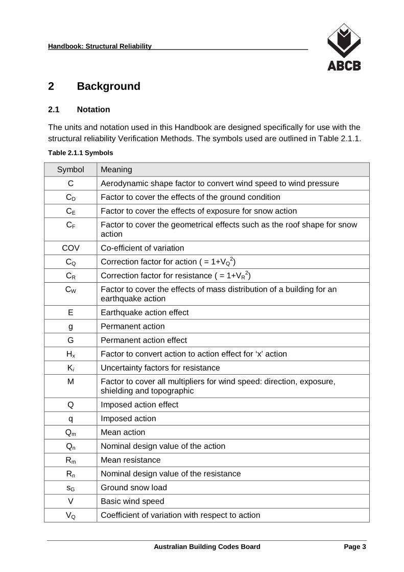
The units and notation used in this Handbook are designed specifically for use with the structural reliability Verification Methods. The symbols used are outlined in Table 2.1.1.
Table 2.1.1 Symbols
Symbol Meaning
C Aerodynamic shape factor to convert wind speed to wind pressure
CD Factor to cover the effects of the ground condition
CE Factor to cover the effects of exposure for snow action
CF Factor to cover the geometrical effects such as the roof shape for snow action
COV Co-efficient of variation
CQ Correction factor for action ( = 1+VQ2)
CR Correction factor for resistance ( = 1+VR2)
CW Factor to cover the effects of mass distribution of a building for an earthquake action
E Earthquake action effect
g Permanent action
G Permanent action effect
Hx Factor to convert action to action effect for ‘x’ action
Ki Uncertainty factors for resistance
M Factor to cover all multipliers for wind speed: direction, exposure, shielding and topographic
Q Imposed action effect
q Imposed action
Qm Mean action
Qn Nominal design value of the action
Rm Mean resistance
Rn Nominal design value of the resistance
sG Ground snow load
V Basic wind speed
VQ Coefficient of variation with respect to action
Australian Building Codes Board Page 3

Handbook: Structural Reliability
Symbol Meaning
VR Coefficient of variation with respect to resistance
W Wind action effect
β Beta, with respect to structural reliability, structural reliability index
ϒ Gamma, with respect to structural reliability, load factor
φ Phi, with respect to structural reliability, capacity factor
2.2 Importance Levels Table 2.2.1 describes the Importance Levels used within this Handbook and referred to within the NCC (as per Table B1.2a).
Table 2.2.1 Importance Levels as per Table B1.2a of the NCC
Importance Level Building Types
1 Buildings or structures presenting a low degree of hazard to life and other property in the case of failure.
2 Buildings or structures not included in Importance Levels 1, 3 and 4.
3 Buildings or structures that are designed to contain a large number of people.
4 Buildings or structures that are essential to post-disaster recovery or associated with hazardous facilities.
Australian Building Codes Board Page 4

Handbook: Structural Reliability
2.3 Hierarchy of Performance Specification
There are various levels of performance specifications, from prescriptive, which involve detailed descriptions of how the process should be completed, to pure performance which allows a greater degree of freedom in achieving the same requirements or objectives. Figure 2.3.1 describes the relationship of prescriptive and performance based specifications and where a Verification Method sits within this relationship. The structural reliability Verification Methods are predominately performance based solutions, but they are prescriptive in the determination of actions in order to provide comparable indices and ensure a level of safety in line with the current NCC requirements.
Figure 2.3.1 Level of Performance Specification
Australian Building Codes Board Page 5

Handbook: Structural Reliability
2.4 Structural Performance Requirements The NCC provides four clauses regarding structural Performance Requirements. Only the first two clauses, BP1.1 and BP1.2 of Volume One and the first three subclauses of Volume Two, P2.1.1(a), (b) and (c), address general structural performance. The concept of a reliability index can be used to quantify the structural performance of these clauses.
In order to meet these Performance Requirements through the Verification Methods, any new and/or innovative structural component or connection is required to demonstrate that it achieves or exceeds the target reliability indices using the method outlined in these Verification Methods. This Handbook is mainly concerned with illustrating how this can be achieved.
BP1.1 and P2.1.1 (a) and (b) consist of two parts:
(a) a listing of the required performance attributes; and
(b) a listing of the factors to be considered, namely the actions to which a building ‘may reasonably be subjected’.
The list of performance attributes covers the serviceability performance, strength performance and robustness. The concept of reliability index is applicable mainly to strength and serviceability performance.
BP1.2 and P2.1.1(c) cover general principles in formulating structural resistance.
The Verification Methods are specifically arranged to cover strength performance that is the relationship between the actions (described in BP1.1 and P2.1.1(a) and (b)) and the resistance (described in BP1.2 and P2.1.1(c)).
The Verification Method is one way, but not the only way, to demonstrate compliance with the NCC Performance Requirements. There are other structural Performance Requirements in the NCC that are not covered by these Verification Methods.
Australian Building Codes Board Page 6
Handbook: Structural Reliability
3 Structural Reliability
3.1 Background to Reliability Structural reliability is an overall concept covering structural actions, response and resistance, workmanship and quality control, all of which are mutually dependent.
In this Handbook, reliability is used as a means for verification of strength of structures subjected to known or foreseeable types of actions such as permanent, imposed, wind, snow and earthquake. As such, it involves mainly structural actions and resistance. It means that the levels of workmanship and quality control are assumed to be maintained in accordance with current standards and practice and appropriately accounted for in the resistance model. It is applicable to the design of structural elements.
Structural reliability can be quantified by failure probability (pF) or reliability index (β), which are connected by the relation β = - Φ-1(pF). In the NCC, target reliability indices are set for structural components and connections. Structural components and connections, for which there is no corresponding NCC Deemed-to-Satisfy Provisions or referenced documents, can choose to meet the target reliability indices in order to demonstrate compliance and satisfy the relevant Performance Requirement/s for strength.
The NCC target structural reliability indices are set as the averages of the reliability indices found in current design practice for steel, concrete and timber. The reference period for this target is one year.
3.2 Reliability Indices BV1 and V2.1.1 seek to quantify structural reliability performance by means of a reliability index. This is where target reliability indices are set and components are tested against these values. New materials and methods of design, outside the limits of a Deemed-to-Satisfy Solution, can use the Verification Methods to demonstrate that their corresponding reliability indices are equal to or greater than the target reliabilities and considered compliant with the NCC. The reliability index could be thought of as a form of safety factor that includes the uncertainties in the determination of the actions and resistances.
3.3 Primary and secondary structural components The structural reliability Verification Methods distinguish between primary and secondary structural components and connections. It explains primary structural components or connections as those whose failure could result in collapse of the building, structure or other property (as defined by the NCC). This implies that the
Australian Building Codes Board Page 7
Handbook: Structural Reliability
structural reliability of components or connections within a buildings’ structural system, that affect either the building itself, a structure as part of or adjoining the building or other property, need to meet the unadjusted values. All other component or connections in the structural system that do not affect the building, structure or other property are considered to be secondary and the structural reliability indices can be reduced.
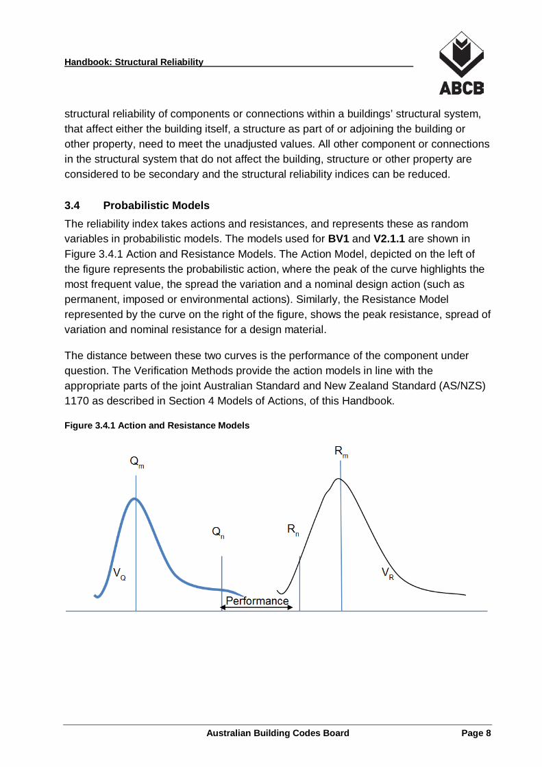
3.4 Probabilistic Models The reliability index takes actions and resistances, and represents these as random variables in probabilistic models. The models used for BV1 and V2.1.1 are shown in Figure 3.4.1 Action and Resistance Models. The Action Model, depicted on the left of the figure represents the probabilistic action, where the peak of the curve highlights the most frequent value, the spread the variation and a nominal design action (such as permanent, imposed or environmental actions). Similarly, the Resistance Model represented by the curve on the right of the figure, shows the peak resistance, spread of variation and nominal resistance for a design material.
The distance between these two curves is the performance of the component under question. The Verification Methods provide the action models in line with the appropriate parts of the joint Australian Standard and New Zealand Standard (AS/NZS) 1170 as described in Section 4 Models of Actions, of this Handbook.
Figure 3.4.1 Action and Resistance Models
Australian Building Codes Board Page 8
Handbook: Structural Reliability
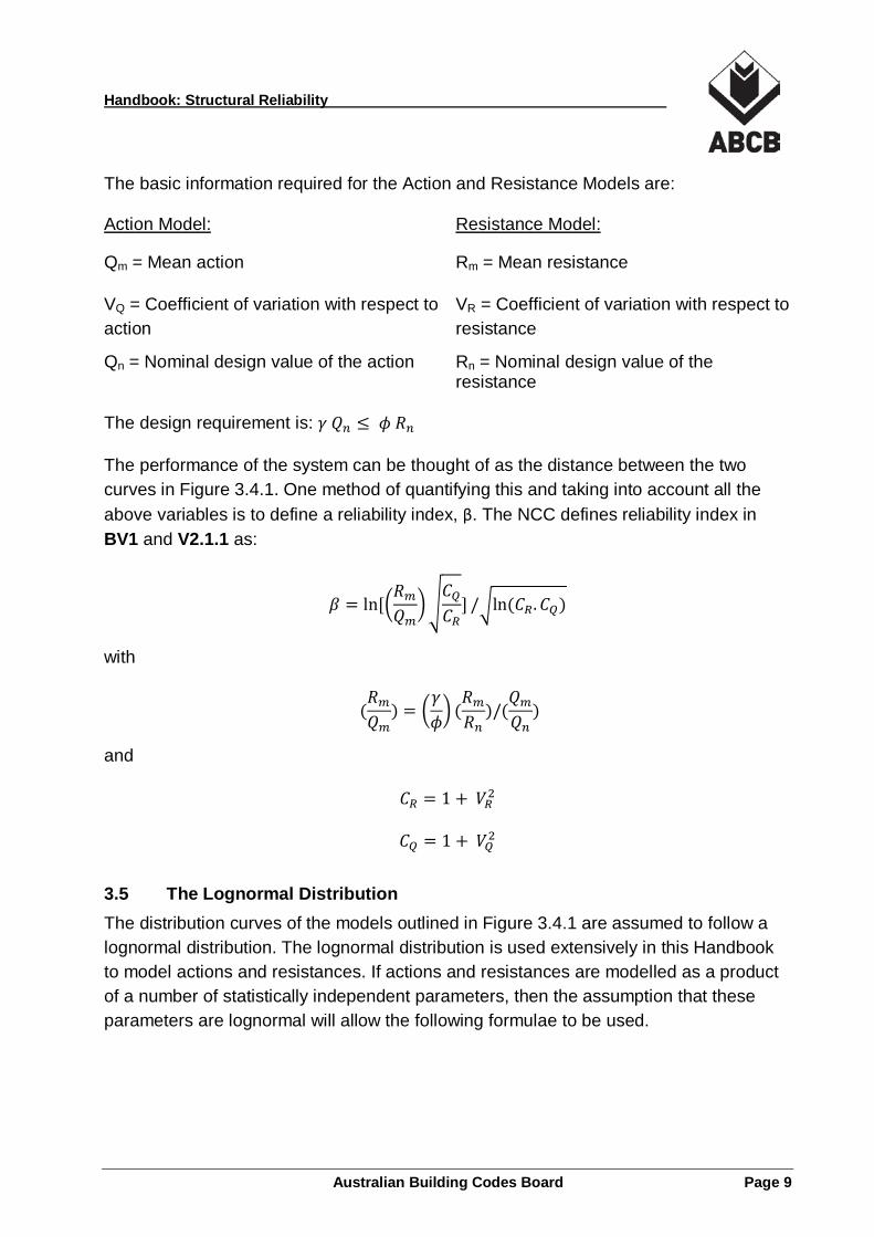
The basic information required for the Action and Resistance Models are: Action Model: Resistance Model:
Qm = Mean action
VQ = Coefficient of variation with respect to action
Qn = Nominal design value of the action
Rm = Mean resistance
VR = Coefficient of variation with respect to resistance
Rn = Nominal design value of the resistance
The design requirement is: 𝛾𝛾 𝑄𝑄𝑛𝑛 ≤ 𝜙𝜙 𝑅𝑅𝑛𝑛
The performance of the system can be thought of as the distance between the two curves in Figure 3.4.1. One method of quantifying this and taking into account all the above variables is to define a reliability index, β. The NCC defines reliability index in BV1 and V2.1.1 as:
𝛽𝛽 = ln[�𝑅𝑅𝑚𝑚𝑄𝑄𝑚𝑚
��𝐶𝐶𝑄𝑄𝐶𝐶𝑅𝑅
] /�ln (𝐶𝐶𝑅𝑅.𝐶𝐶𝑄𝑄)
with
(𝑅𝑅𝑚𝑚𝑄𝑄𝑚𝑚
) = �𝛾𝛾𝜙𝜙� (
𝑅𝑅𝑚𝑚𝑅𝑅𝑛𝑛
)/(𝑄𝑄𝑚𝑚𝑄𝑄𝑛𝑛
)
and
𝐶𝐶𝑅𝑅 = 1 + 𝑉𝑉𝑅𝑅2
𝐶𝐶𝑄𝑄 = 1 + 𝑉𝑉𝑄𝑄2
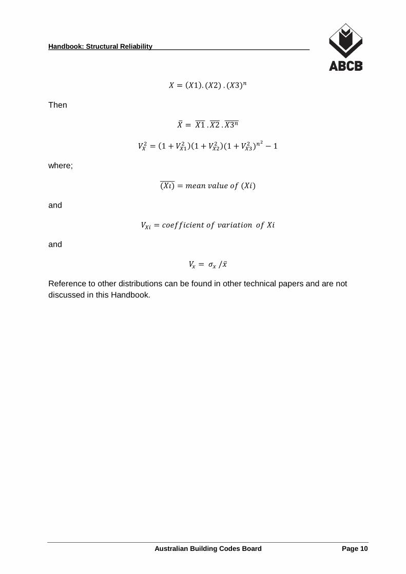
3.5 The Lognormal Distribution The distribution curves of the models outlined in Figure 3.4.1 are assumed to follow a lognormal distribution. The lognormal distribution is used extensively in this Handbook to model actions and resistances. If actions and resistances are modelled as a product of a number of statistically independent parameters, then the assumption that these parameters are lognormal will allow the following formulae to be used.
Australian Building Codes Board Page 9
Handbook: Structural Reliability
𝑋𝑋 = (𝑋𝑋1). (𝑋𝑋2) . (𝑋𝑋3)𝑛𝑛
Then
𝑋𝑋� = 𝑋𝑋1���� .𝑋𝑋2���� .𝑋𝑋3𝑛𝑛�����
𝑉𝑉𝑋𝑋2 = (1 + 𝑉𝑉𝑋𝑋12 )(1 + 𝑉𝑉𝑋𝑋22 )(1 + 𝑉𝑉𝑋𝑋32 )𝑛𝑛2 − 1
where;
(𝑋𝑋𝑋𝑋)������ = 𝑚𝑚𝑚𝑚𝑚𝑚𝑚𝑚 𝑣𝑣𝑚𝑚𝑣𝑣𝑣𝑣𝑚𝑚 𝑜𝑜𝑜𝑜 (𝑋𝑋𝑋𝑋)
and
𝑉𝑉𝑋𝑋𝑋𝑋 = 𝑐𝑐𝑜𝑜𝑚𝑚𝑜𝑜𝑜𝑜𝑋𝑋𝑐𝑐𝑋𝑋𝑚𝑚𝑚𝑚𝑐𝑐 𝑜𝑜𝑜𝑜 𝑣𝑣𝑚𝑚𝑣𝑣𝑋𝑋𝑚𝑚𝑐𝑐𝑋𝑋𝑜𝑜𝑚𝑚 𝑜𝑜𝑜𝑜 𝑋𝑋𝑋𝑋
and
𝑉𝑉𝑥𝑥 = 𝜎𝜎𝑥𝑥 /�̅�𝑥
Reference to other distributions can be found in other technical papers and are not discussed in this Handbook.
Australian Building Codes Board Page 10

Handbook: Structural Reliability
4 Models of Actions A set of probabilistic Action Models used in the Verification Methods are given below for the purpose of computing the reliability indices. The models represent typical characteristics of the actions as related to Australian conditions, but not specific to a particular location or a type of occupancy.
Numerical values for the models of actions to be used in the computation of the reliability indices are given below. Appendix B provides further details on how these figures are derived.
4.1 Permanent Action For the purpose of the NCC, the following model for permanent action effect is to be used:
G = HG . g
where:
G = permanent action effect
HG = factor to convert action to action effect
g = permanent action
The corresponding nominal design action effect is: Gn = HGn . gn
Therefore: (G/Gn) = (HG/HGn) . (g/gn)
The Mean and COV values for the parameters have been assessed as follows:
MEAN (HG/HGn) = 0.95 COV (HG/HGn) = 0.07
MEAN (g/gn) = 1.05 COV (g/gn) = 0.07
Therefore:
MEAN (G/Gn) = 1.0 COV (G/Gn) = 0.10
This is the model for permanent action to be used in the calculation of the reliability indices.
Australian Building Codes Board Page 11
Handbook: Structural Reliability
4.2 Imposed Action For the purpose of this document, the following model for imposed action effect is to be used:
Q = HQ . q
where:
Q = imposed action effect
HQ = factor to convert action to action effect
q = imposed action
The corresponding nominal design action effect is: Qn = HQn . qn
Therefore: (Q/Qn) = (HQ/HQn) . (q/qn)
The Mean and COV values for the parameters have been assessed as follows:
MEAN (HQ/HQn) = 0.95 COV (HQ/HQn) = 0.07
MEAN (q/qn) = 0.52 COV (q/qn) = 0.43
Therefore: MEAN(Q/Qn) = 0.50 COV (Q/Qn) = 0.43
4.3 Wind Action For the purpose of this document, only buildings not sensitive to wind dynamic effects are considered. The wind action effect models are to have the following format:
W = HW . C . (M . V)2
where:
V = the basic wind speed whose statistics are available and given in AS/NZS 1170.2 in terms of annual probability of exceedance
M = factor to cover all multipliers for the wind speed: direction, exposure, shielding and topographic
C = the aerodynamic shape factor to convert wind speed to wind pressure
HW = factor to convert wind pressure to wind action effect
Australian Building Codes Board Page 12
Handbook: Structural Reliability
The corresponding nominal design wind action effect is: Wn = HWn . Cn . (Mn . Vn)2
Therefore: (W/Wn) = (HW/HWn).(C/Cn).(M/Mn)2.(V/Vn)2
The Mean and COV values for the parameters have been assessed as follows:
MEAN (HW/HWn) = 0.8 COV (HW/HWn) = 0.10
MEAN (C/Cn) = 1.0 COV (C/Cn) = 0.2
MEAN (M/Mn) = 1.0 COV (M/Mn) = 0.15
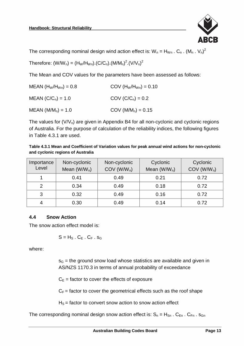
The values for (V/Vn) are given in Appendix B4 for all non-cyclonic and cyclonic regions of Australia. For the purpose of calculation of the reliability indices, the following figures in Table 4.3.1 are used.
Table 4.3.1 Mean and Coefficient of Variation values for peak annual wind actions for non-cyclonic and cyclonic regions of Australia
Importance Level
Non-cyclonic Mean (W/Wn)
Non-cyclonic COV (W/Wn)
Cyclonic Mean (W/Wn)
Cyclonic COV (W/Wn)
1 0.41 0.49 0.21 0.72
2 0.34 0.49 0.18 0.72
3 0.32 0.49 0.16 0.72
4 0.30 0.49 0.14 0.72
4.4 Snow Action The snow action effect model is:
S = HS . CE . CF . sG
where:
sG = the ground snow load whose statistics are available and given in AS/NZS 1170.3 in terms of annual probability of exceedance
CE = factor to cover the effects of exposure
CF = factor to cover the geometrical effects such as the roof shape
HS = factor to convert snow action to snow action effect
The corresponding nominal design snow action effect is: Sn = HSn . CEn . CFn . sGn
Australian Building Codes Board Page 13
Handbook: Structural Reliability
Therefore: (S/Sn) = (HS/HSn).(CE/CEn).(CF/CFn).(sG/sGn)
The MEAN and COV values for the parameters have been assessed as follows:
MEAN (HS/HSn) = 0.9 COV(HS/HSn) = 0.10
MEAN (CE/CEn) = 1.0 COV(CE/CEn) = 0.15
MEAN (CF/CFn) = 1.0 COV(CF/CFn) = 0.10
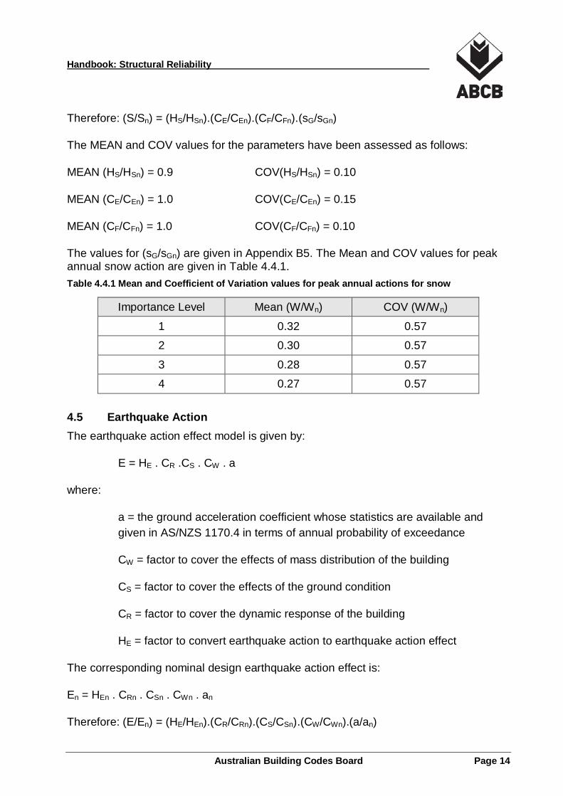
The values for (sG/sGn) are given in Appendix B5. The Mean and COV values for peak annual snow action are given in Table 4.4.1. Table 4.4.1 Mean and Coefficient of Variation values for peak annual actions for snow
Importance Level Mean (W/Wn) COV (W/Wn)
1 0.32 0.57
2 0.30 0.57
3 0.28 0.57
4 0.27 0.57
4.5 Earthquake Action The earthquake action effect model is given by:
E = HE . CR .CS . CW . a
where:
a = the ground acceleration coefficient whose statistics are available and given in AS/NZS 1170.4 in terms of annual probability of exceedance
CW = factor to cover the effects of mass distribution of the building
CS = factor to cover the effects of the ground condition
CR = factor to cover the dynamic response of the building
HE = factor to convert earthquake action to earthquake action effect
The corresponding nominal design earthquake action effect is:
En = HEn . CRn . CSn . CWn . an
Therefore: (E/En) = (HE/HEn).(CR/CRn).(CS/CSn).(CW/CWn).(a/an)
Australian Building Codes Board Page 14
Handbook: Structural Reliability
The MEAN and COV values for the parameters have been assessed as follows:
MEAN (HE/HEn) = 0.9 COV(HE/HEn) = 0.1
MEAN (CR/CRn) = 1.0 COV(CR/CRn) = 0.1
MEAN (CS/CSn) = 1.0 COV(CS/CSn) = 0.1
MEAN (CW/CWn) = 1.0 COV(CW/CWn) = 0.1
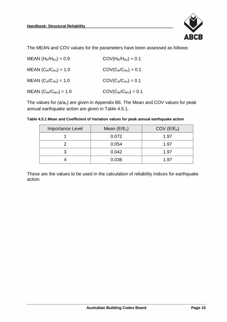
The values for (a/an) are given in Appendix B6. The Mean and COV values for peak annual earthquake action are given in Table 4.5.1.
Table 4.5.1 Mean and Coefficient of Variation values for peak annual earthquake action
Importance Level Mean (E/En) COV (E/En)
1 0.072 1.97
2 0.054 1.97
3 0.042 1.97
4 0.036 1.97
These are the values to be used in the calculation of reliability indices for earthquake action.
Australian Building Codes Board Page 15
Handbook: Structural Reliability
5 Model of Resistance
5.1 Developing resistance models The Australian Standards (AS/NZS 1170) for design were formulated upon components and connections. A model of resistance for components or connections must therefore be created for the computation of reliability indices.
The purpose of creating a Resistance Model is to account for all sources of uncertainties in the determination of resistance of a structural component or connection. The resistance, R, a random variable is related to the standard specified resistance RN, a deterministic value, through the general equation below. In which Km, Kf, Ks … are factors that contribute to the uncertainties in the assessment of the resistance and are random values assumed to be statistically independent.
R = Km. Kf. Ks … Rn
The sources of uncertainties must include, but are not limited to the following;
• variability in the mechanical properties of the materials;
• variation in dimensions as the result of fabrication or construction processes; and
• uncertainties in the structural modelling of the component. Another source of uncertainty is the rounding due to structural component’s availability in discrete sizes. This source of variability is ignored as it is generally conservative to do so.
If all the above variables are assumed to be of lognormal distribution and statistically independent, then the mean value and the coefficient of variation of R can be established as follows:
Mean (R) = Mean (Km). Mean (Kf). Mean (Ks)… Rn
(VR)2 = (VKm)2 + (VKf)2 + (VKs)2 + …
The value of RN is usually established by identifying the major parameters that affect the behaviour of the component and constructing appropriate structural models to account for their effects. RN must be formulated using five percentile characteristic material properties in accordance with BP1.2 and P2.1.1(c) of the NCC. Examples can be found in structural design standards for steel, concrete and timber.
The value of Km to account for variability of the relevant mechanical properties is usually obtained from test data used for quality control of the material manufacturing process.
Australian Building Codes Board Page 16

Handbook: Structural Reliability
The value of Kf to account for variability of the manufacturing/construction process is obtained from the established allowable tolerance and measurement of the dimensions of the component.
The value of Ks to account for variability in structural modelling is obtained from the test research data used in the construction of the structural model.
Alternatively, a combined assessment of all variability can be established by testing an adequate number of full size samples of the component. This method is referred to as design by testing and is acceptable in most Australian material design standards. The outcome is a direct assessment of the resistance design value as a five percentile value of resistance. Allowance has to be made for the limited number of tests to be able to gain adequate confidence in the outcomes.
A flow chart for the process of establishing the Resistance Model is outlined in Figure 5.1.1.
Figure 5.1.1 Flowchart for establishing a Resistance Model
Australian Building Codes Board Page 17
Handbook: Structural Reliability
6 Structural Reliability Verification
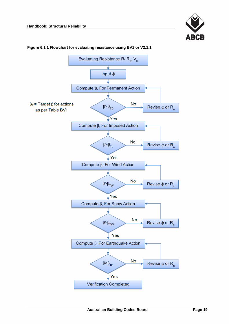
6.1 Methods of structural reliability verification After the assessment of the Action Models and the Resistance Models, the reliability index can now be computed. There are a number of ways to achieve this with varying degrees of difficulty and flexibility. The method outlined in BV1 and V2.1.1 is designed to cope with new/innovative structural products for which there are no standard specifications. It requires the reliability indices for the proposed product to be equal to or greater than the target reliability indices established in BV1 and V2.1.1 for each of the relevant actions separately. The selected Φ value for design is the minimum value that satisfies all target reliability indices.
By using lognormal distribution for both the actions and resistances, it is possible to have a close-form expression for the reliability indices. Other more sophisticated methods for computing the reliability indices can be used but it is up to the proposer to justify their appropriateness.
The method is expected to be used in situations where there are no appropriate DtS references. The targets are set at the average values of those found in current practice using steel, concrete or timber.
A flowchart for the method of BV1 and V2.1.1 is shown in Figure 6.1.1.
Australian Building Codes Board Page 18
Handbook: Structural Reliability
Figure 6.1.1 Flowchart for evaluating resistance using BV1 or V2.1.1
Australian Building Codes Board Page 19
Handbook: Structural Reliability
6.2 Using the Verification Methods The following examples demonstrate various ways to use the Verification Methods described in BV1 and V2.1.1. These examples are followed by a brief discussion regarding the assumptions taken in order to present the results shown. It should be noted that these examples only highlight the key process steps and a real life scenario should be accompanied by appropriate experience, expert judgement or peer review in analysing a new product or system.
6.3 Example 1: Structural Reliability for a New Timber Product Problem: To determine the design bending stress and appropriate φ factor for a new timber product to be placed on the Australian market. Other design requirements are as in AS 1720 and load factors are as in AS/NZS 1170.0.
Product Data:
1155 full size samples, measured and tested to a 5 minute duration test. Mean bending stress, fu = 37.7 Mega Pascals (MPa) Coefficient of variation, Vfu = 0.40 Dimensional variations: Width b (Mean/Nominal) = 1.0, Vb = 0.02 Depth d (Mean/Nominal) =1.0, Vd = 0.02
Solution:
Establish the Resistance Model: The moment capacity of the section is the key parameter in assessing bending resistance following the model used in AS 1720.
R = kt . Z . fu
where:
kt = factor to account for load duration. There are a few other factors that affect bending strength such as moisture, stability etc. as specified in AS 1720. For this example, we will seek to establish basic design stress thus only load duration factor is taken into account.
Z = section modulus
fu = failure stress
Australian Building Codes Board Page 20
Handbook: Structural Reliability
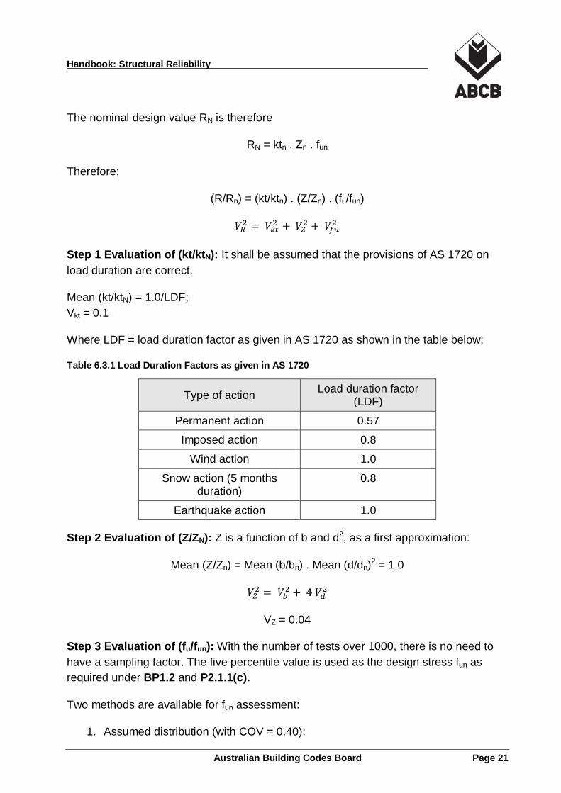
The nominal design value RN is therefore
RN = ktn . Zn . fun
Therefore;
(R/Rn) = (kt/ktn) . (Z/Zn) . (fu/fun)
𝑉𝑉𝑅𝑅2 = 𝑉𝑉𝑘𝑘𝑘𝑘2 + 𝑉𝑉𝑍𝑍2 + 𝑉𝑉𝑓𝑓𝑓𝑓2
Step 1 Evaluation of (kt/ktN): It shall be assumed that the provisions of AS 1720 on load duration are correct.
Mean (kt/ktN) = 1.0/LDF; Vkt = 0.1
Where LDF = load duration factor as given in AS 1720 as shown in the table below;
Table 6.3.1 Load Duration Factors as given in AS 1720
Type of action Load duration factor (LDF)
Permanent action 0.57
Imposed action 0.8
Wind action 1.0
Snow action (5 months duration)
0.8
Earthquake action 1.0
Step 2 Evaluation of (Z/ZN): Z is a function of b and d2, as a first approximation:
Mean (Z/Zn) = Mean (b/bn) . Mean (d/dn)2 = 1.0
𝑉𝑉𝑍𝑍2 = 𝑉𝑉𝑏𝑏2 + 4 𝑉𝑉𝑑𝑑2
VZ = 0.04
Step 3 Evaluation of (fu/fun): With the number of tests over 1000, there is no need to have a sampling factor. The five percentile value is used as the design stress fun as required under BP1.2 and P2.1.1(c).
Two methods are available for fun assessment:
1. Assumed distribution (with COV = 0.40):
Australian Building Codes Board Page 21
Handbook: Structural Reliability
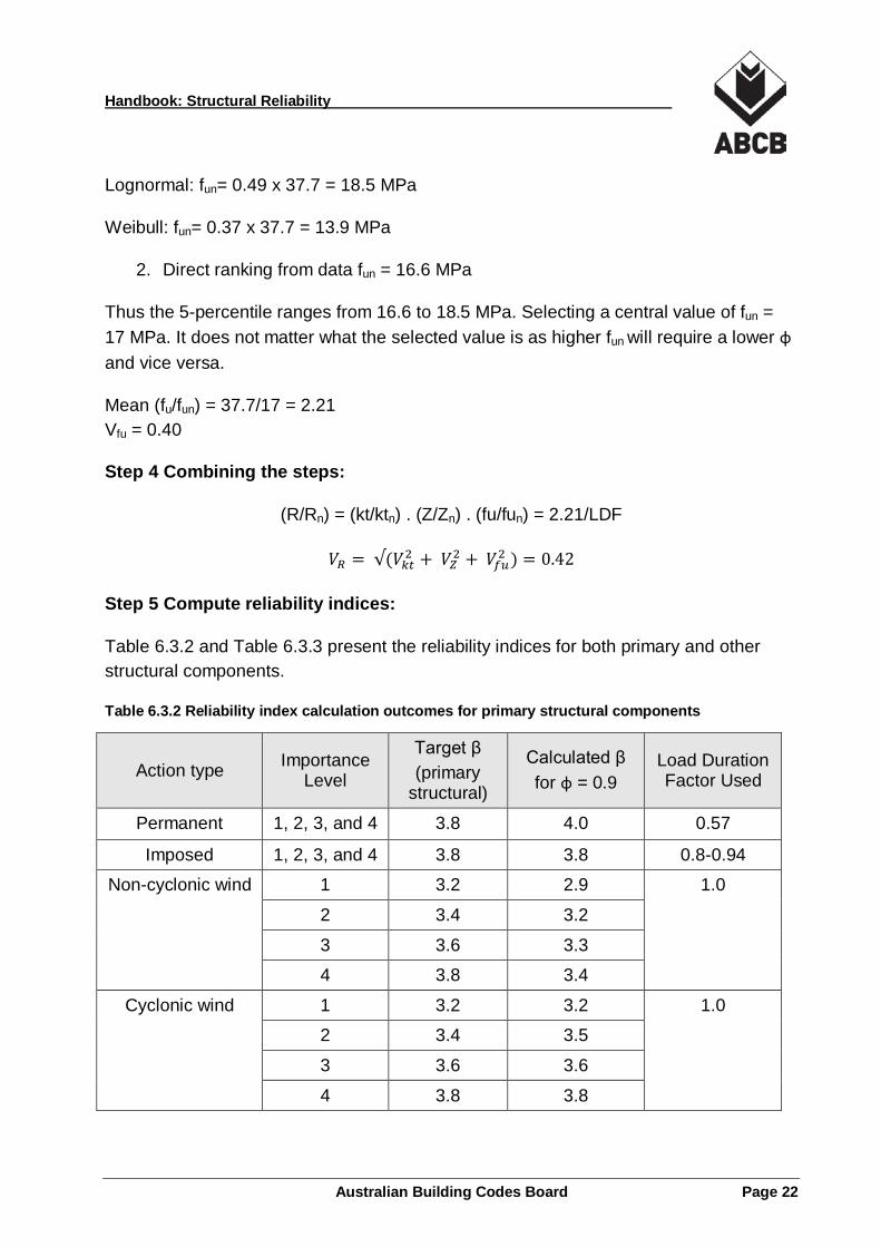
Lognormal: fun= 0.49 x 37.7 = 18.5 MPa
Weibull: fun= 0.37 x 37.7 = 13.9 MPa
2. Direct ranking from data fun = 16.6 MPa
Thus the 5-percentile ranges from 16.6 to 18.5 MPa. Selecting a central value of fun = 17 MPa. It does not matter what the selected value is as higher fun will require a lower φ and vice versa.
Mean (fu/fun) = 37.7/17 = 2.21 Vfu = 0.40
Step 4 Combining the steps:
(R/Rn) = (kt/ktn) . (Z/Zn) . (fu/fun) = 2.21/LDF
𝑉𝑉𝑅𝑅 = √(𝑉𝑉𝑘𝑘𝑘𝑘2 + 𝑉𝑉𝑍𝑍2 + 𝑉𝑉𝑓𝑓𝑓𝑓2 ) = 0.42
Step 5 Compute reliability indices:
Table 6.3.2 and Table 6.3.3 present the reliability indices for both primary and other structural components.
Table 6.3.2 Reliability index calculation outcomes for primary structural components
Action type Importance Level
Target β (primary
structural)
Calculated β for φ = 0.9
Load Duration Factor Used
Permanent 1, 2, 3, and 4 3.8 4.0 0.57
Imposed 1, 2, 3, and 4 3.8 3.8 0.8-0.94
Non-cyclonic wind 1 3.2 2.9 1.0
Non-cyclonic wind 2 3.4 3.2 1.0
Non-cyclonic wind 3 3.6 3.3 1.0
Non-cyclonic wind 4 3.8 3.4 1.0
Cyclonic wind 1 3.2 3.2 1.0
Cyclonic wind 2 3.4 3.5 1.0
Cyclonic wind 3 3.6 3.6 1.0
Cyclonic wind 4 3.8 3.8 1.0
Australian Building Codes Board Page 22
Handbook: Structural Reliability
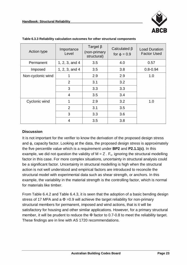
Table 6.3.3 Reliability calculation outcomes for other structural components
Action type Importance Level
Target β (non-primary
structural)
Calculated β for φ = 0.9
Load Duration Factor Used
Permanent 1, 2, 3, and 4 3.5 4.0 0.57
Imposed 1, 2, 3, and 4 3.5 3.8 0.8-0.94
Non-cyclonic wind 1 2.9 2.9 1.0
Non-cyclonic wind 2 3.1 3.2 1.0
Non-cyclonic wind 3 3.3 3.3 1.0
Non-cyclonic wind 4 3.5 3.4 1.0
Cyclonic wind 1 2.9 3.2 1.0
Cyclonic wind 2 3.1 3.5 1.0
Cyclonic wind 3 3.3 3.6 1.0
Cyclonic wind 4 3.5 3.8 1.0
Discussion It is not important for the verifier to know the derivation of the proposed design stress and φ, capacity factor. Looking at the data, the proposed design stress is approximately the five percentile value which is a requirement under BP2 and P2.1.1(c). In this example, we did not question the validity of M = Z . Fu. ignoring the structural modelling factor in this case. For more complex situations, uncertainty in structural analysis could be a significant factor. Uncertainty in structural modelling is high when the structural action is not well understood and empirical factors are introduced to reconcile the structural model with experimental data such as shear strength, or anchors. In this example, the variability in the material strength is the controlling factor, which is normal for materials like timber.
From Table 6.4.2 and Table 6.4.3, it is seen that the adoption of a basic bending design stress of 17 MPA and a Φ =0.9 will achieve the target reliability for non-primary structural members for permanent, imposed and wind actions, that is it will be satisfactory for housing and other similar applications. However, for a primary structural member, it will be prudent to reduce the Φ factor to 0.7-0.8 to meet the reliability target. These findings are in line with AS 1720 recommendations.
Australian Building Codes Board Page 23
Handbook: Structural Reliability
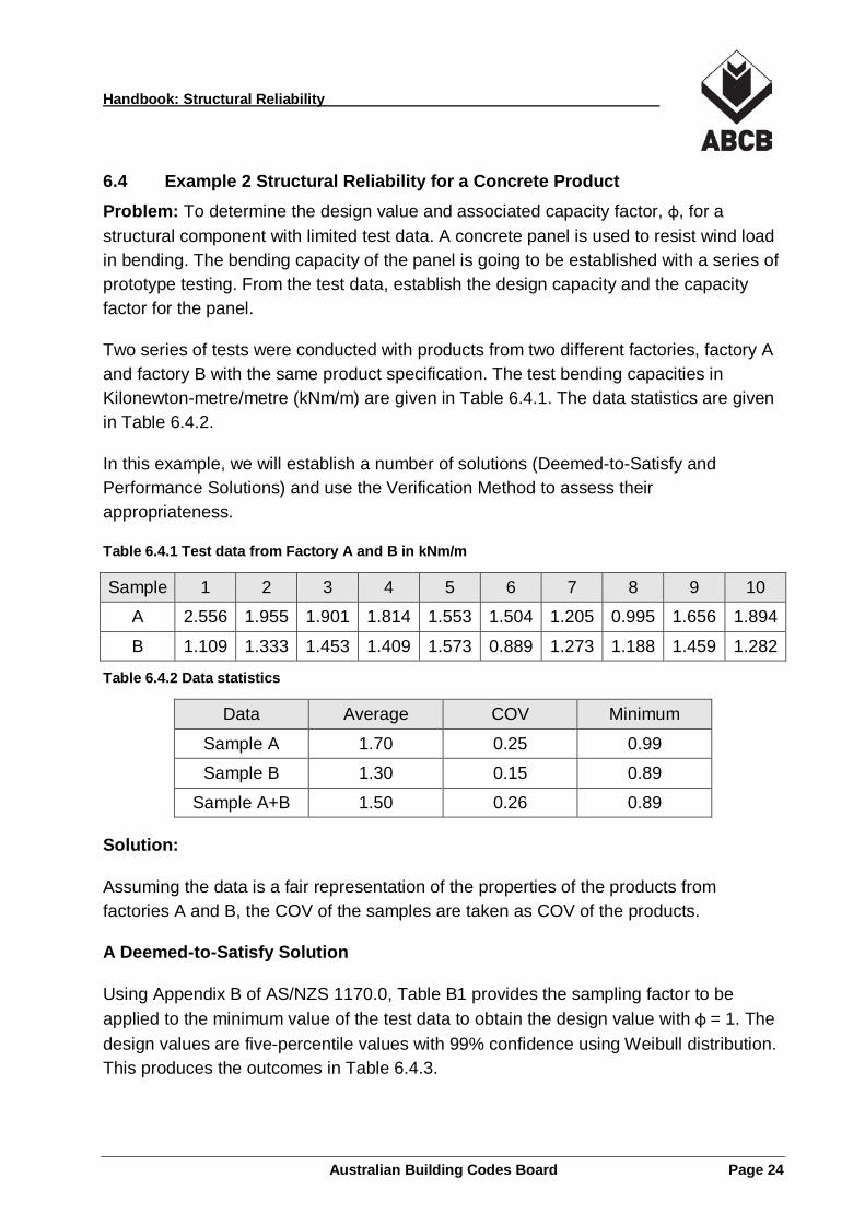
6.4 Example 2 Structural Reliability for a Concrete Product Problem: To determine the design value and associated capacity factor, φ, for a structural component with limited test data. A concrete panel is used to resist wind load in bending. The bending capacity of the panel is going to be established with a series of prototype testing. From the test data, establish the design capacity and the capacity factor for the panel.
Two series of tests were conducted with products from two different factories, factory A and factory B with the same product specification. The test bending capacities in Kilonewton-metre/metre (kNm/m) are given in Table 6.4.1. The data statistics are given in Table 6.4.2.
In this example, we will establish a number of solutions (Deemed-to-Satisfy and Performance Solutions) and use the Verification Method to assess their appropriateness.
Table 6.4.1 Test data from Factory A and B in kNm/m
Sample 1 2 3 4 5 6 7 8 9 10
A 2.556 1.955 1.901 1.814 1.553 1.504 1.205 0.995 1.656 1.894
B 1.109 1.333 1.453 1.409 1.573 0.889 1.273 1.188 1.459 1.282
Table 6.4.2 Data statistics
Data Average COV Minimum
Sample A 1.70 0.25 0.99
Sample B 1.30 0.15 0.89
Sample A+B 1.50 0.26 0.89
Solution:
Assuming the data is a fair representation of the properties of the products from factories A and B, the COV of the samples are taken as COV of the products.
A Deemed-to-Satisfy Solution
Using Appendix B of AS/NZS 1170.0, Table B1 provides the sampling factor to be applied to the minimum value of the test data to obtain the design value with φ = 1. The design values are five-percentile values with 99% confidence using Weibull distribution. This produces the outcomes in Table 6.4.3.
Australian Building Codes Board Page 24
Handbook: Structural Reliability
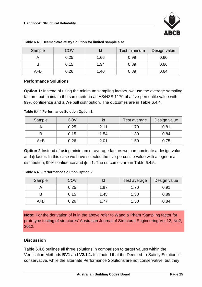
Table 6.4.3 Deemed-to-Satisfy Solution for limited sample size
Sample COV kt Test minimum Design value
A 0.25 1.66 0.99 0.60
B 0.15 1.34 0.89 0.66
A+B 0.26 1.40 0.89 0.64
Performance Solutions
Option 1: Instead of using the minimum sampling factors, we use the average sampling factors, but maintain the same criteria as AS/NZS 1170 of a five-percentile value with 99% confidence and a Weibull distribution. The outcomes are in Table 6.4.4.
Table 6.4.4 Performance Solution Option 1
Sample COV kt Test average Design value
A 0.25 2.11 1.70 0.81
B 0.15 1.54 1.30 0.84
A+B 0.26 2.01 1.50 0.75
Option 2 Instead of using minimum or average factors we can nominate a design value and φ factor. In this case we have selected the five-percentile value with a lognormal distribution, 99% confidence and φ = 1. The outcomes are in Table 6.4.5.
Table 6.4.5 Performance Solution Option 2
Sample COV kt Test average Design value
A 0.25 1.87 1.70 0.91
B 0.15 1.45 1.30 0.89
A+B 0.26 1.77 1.50 0.84
Note: For the derivation of kt in the above refer to Wang & Pham ‘Sampling factor for prototype testing of structures’ Australian Journal of Structural Engineering Vol.12, No2, 2012.
Discussion
Table 6.4.6 outlines all three solutions in comparison to target values within the Verification Methods BV1 and V2.1.1. It is noted that the Deemed-to-Satisfy Solution is conservative, while the alternate Performance Solutions are not conservative, but they
Australian Building Codes Board Page 25
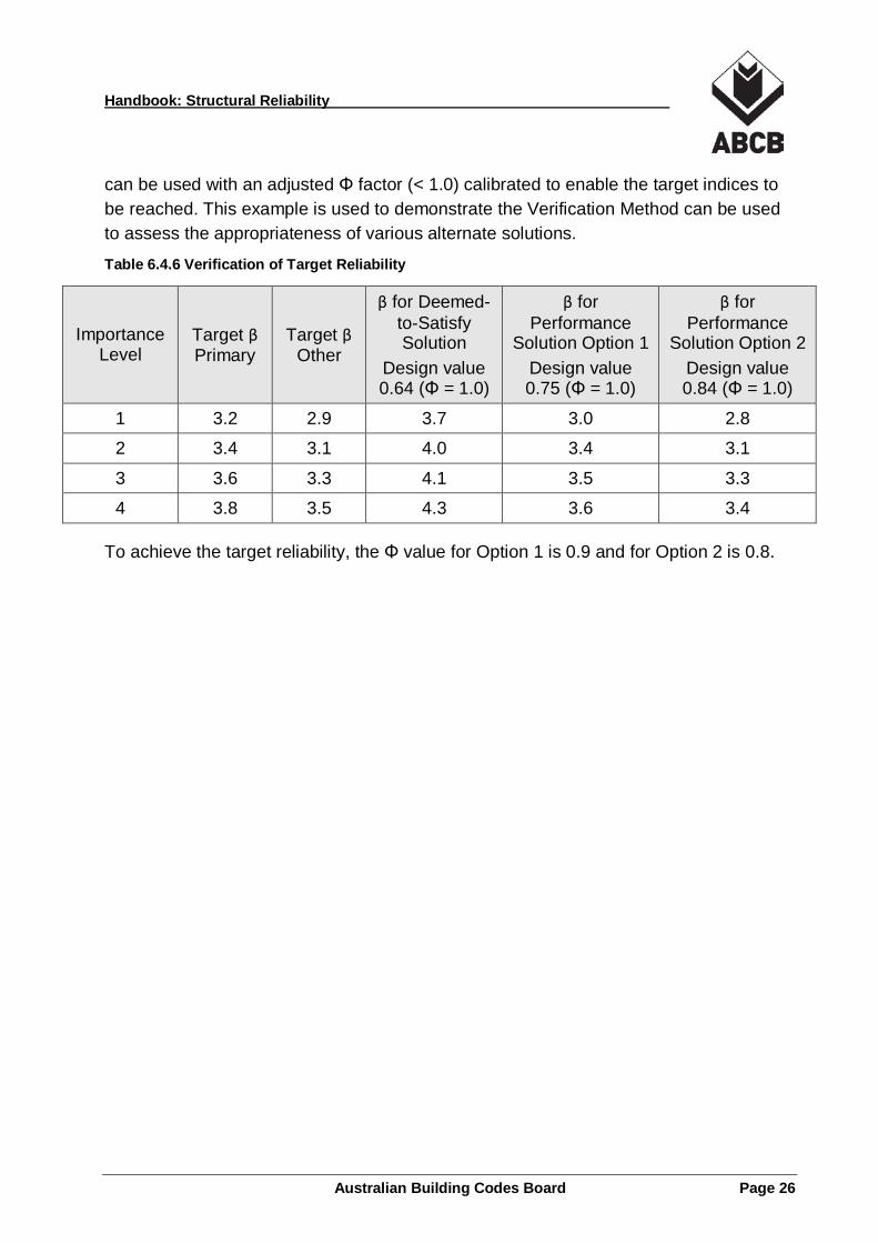
Handbook: Structural Reliability
can be used with an adjusted Φ factor (< 1.0) calibrated to enable the target indices to be reached. This example is used to demonstrate the Verification Method can be used to assess the appropriateness of various alternate solutions.
Table 6.4.6 Verification of Target Reliability
Importance Level
Target β Primary
Target β Other
β for Deemed-to-Satisfy Solution
Design value 0.64 (Φ = 1.0)
β for Performance
Solution Option 1 Design value 0.75 (Φ = 1.0)
β for Performance
Solution Option 2 Design value 0.84 (Φ = 1.0)
1 3.2 2.9 3.7 3.0 2.8
2 3.4 3.1 4.0 3.4 3.1
3 3.6 3.3 4.1 3.5 3.3
4 3.8 3.5 4.3 3.6 3.4
To achieve the target reliability, the Φ value for Option 1 is 0.9 and for Option 2 is 0.8.
Australian Building Codes Board Page 26
Handbook: Structural Reliability
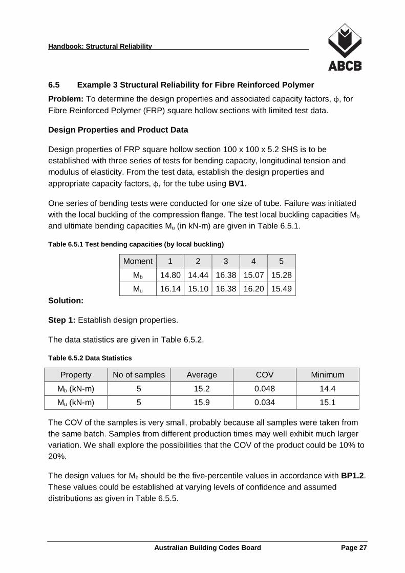
6.5 Example 3 Structural Reliability for Fibre Reinforced Polymer Problem: To determine the design properties and associated capacity factors, φ, for Fibre Reinforced Polymer (FRP) square hollow sections with limited test data.
Design Properties and Product Data
Design properties of FRP square hollow section 100 x 100 x 5.2 SHS is to be established with three series of tests for bending capacity, longitudinal tension and modulus of elasticity. From the test data, establish the design properties and appropriate capacity factors, φ, for the tube using BV1.
One series of bending tests were conducted for one size of tube. Failure was initiated with the local buckling of the compression flange. The test local buckling capacities Mb and ultimate bending capacities Mu (in kN-m) are given in Table 6.5.1.
Table 6.5.1 Test bending capacities (by local buckling)
Moment 1 2 3 4 5
Mb 14.80 14.44 16.38 15.07 15.28
Mu 16.14 15.10 16.38 16.20 15.49 Solution:
Step 1: Establish design properties.
The data statistics are given in Table 6.5.2.
Table 6.5.2 Data Statistics
Property No of samples Average COV Minimum
Mb (kN-m) 5 15.2 0.048 14.4
Mu (kN-m) 5 15.9 0.034 15.1
The COV of the samples is very small, probably because all samples were taken from the same batch. Samples from different production times may well exhibit much larger variation. We shall explore the possibilities that the COV of the product could be 10% to 20%.
The design values for Mb should be the five-percentile values in accordance with BP1.2. These values could be established at varying levels of confidence and assumed distributions as given in Table 6.5.5.
Australian Building Codes Board Page 27
Handbook: Structural Reliability
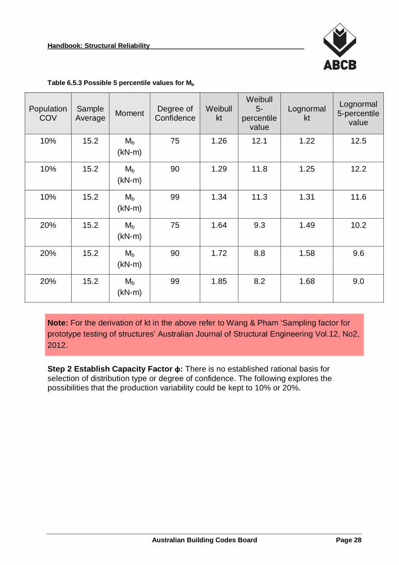
Table 6.5.3 Possible 5 percentile values for Mb
Population COV
Sample Average Moment Degree of
Confidence Weibull
kt
Weibull 5-
percentile value
Lognormal kt
Lognormal 5-percentile
value
10% 15.2 Mb (kN-m)
75 1.26 12.1 1.22 12.5
10% 15.2 Mb (kN-m)
90 1.29 11.8 1.25 12.2
10% 15.2 Mb (kN-m)
99 1.34 11.3 1.31 11.6
20% 15.2 Mb (kN-m)
75 1.64 9.3 1.49 10.2
20% 15.2 Mb (kN-m)
90 1.72 8.8 1.58 9.6
20% 15.2 Mb (kN-m)
99 1.85 8.2 1.68 9.0
Note: For the derivation of kt in the above refer to Wang & Pham ‘Sampling factor for prototype testing of structures’ Australian Journal of Structural Engineering Vol.12, No2, 2012.
Step 2 Establish Capacity Factor φ: There is no established rational basis for selection of distribution type or degree of confidence. The following explores the possibilities that the production variability could be kept to 10% or 20%.
Australian Building Codes Board Page 28
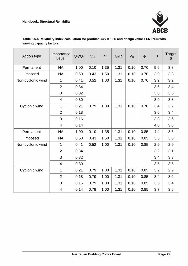
Handbook: Structural Reliability
Table 6.5.4 Reliability index calculation for product COV = 10% and design value 11.6 kN-m with varying capacity factors
Action type Importance Level Qm/Qn VQ ϒ Rm/Rn VR φ β Target
β
Permanent NA 1.00 0.10 1.35 1.31 0.10 0.70 5.6 3.8
Imposed NA 0.50 0.43 1.50 1.31 0.10 0.70 3.9 3.8
Non-cyclonic wind 1 0.41 0.52 1.00 1.31 0.10 0.70 3.2 3.2
Non-cyclonic wind 2 0.34 0.52 1.00 1.31 0.10 0.70 3.6 3.4
Non-cyclonic wind 3 0.32 0.52 1.00 1.31 0.10 0.70 3.8 3.6
Non-cyclonic wind 4 0.30 0.52 1.00 1.31 0.10 0.70 3.9 3.8
Cyclonic wind 1 0.21 0.79 1.00 1.31 0.10 0.70 3.4 3.2
Cyclonic wind 2 0.18 0.79 1.00 1.31 0.10 0.70 3.6 3.4
Cyclonic wind 3 0.16 0.79 1.00 1.31 0.10 0.70 3.8 3.6
Cyclonic wind 4 0.14 0.79 1.00 1.31 0.10 0.70 4.0 3.8
Permanent NA 1.00 0.10 1.35 1.31 0.10 0.85 4.4 3.5
Imposed NA 0.50 0.43 1.50 1.31 0.10 0.85 3.5 3.5
Non-cyclonic wind 1 0.41 0.52 1.00 1.31 0.10 0.85 2.9 2.9
Non-cyclonic wind 2 0.34 0.52 1.00 1.31 0.10 0.85 3.2 3.1
Non-cyclonic wind 3 0.32 0.52 1.00 1.31 0.10 0.85 3.4 3.3
Non-cyclonic wind 4 0.30 0.52 1.00 1.31 0.10 0.85 3.5 3.5
Cyclonic wind 1 0.21 0.79 1.00 1.31 0.10 0.85 3.2 2.9
Cyclonic wind 2 0.18 0.79 1.00 1.31 0.10 0.85 3.4 3.2
Cyclonic wind 3 0.16 0.79 1.00 1.31 0.10 0.85 3.5 3.4
Cyclonic wind 4 0.14 0.79 1.00 1.31 0.10 0.85 3.7 3.6
Australian Building Codes Board Page 29

Handbook: Structural Reliability
Table 6.5.5 Reliability index calculation for product COV=20% and design value 9.0 kN-m with varying capacity factors
Action type Importance
Level Qm/Qn VQ ϒ Rm/Rn VR φ β Target
β
Permanent NA 1.00 0.10 1.35 1.68 0.20 0.80 4.6 3.8
Imposed NA 0.50 0.43 1.50 1.68 0.20 0.80 4.2 3.8
Non-cyclonic wind 1 0.41 0.52 1.00 1.68 0.20 0.80 3.2 3.2
Non-cyclonic wind 2 0.34 0.52 1.00 1.68 0.20 0.80 3.6 3.4
Non-cyclonic wind 3 0.32 0.52 1.00 1.68 0.20 0.80 3.7 3.6
Non-cyclonic wind 4 0.30 0.52 1.00 1.68 0.20 0.80 3.9 3.8
Cyclonic wind 1 0.21 0.79 1.00 1.68 0.20 0.80 3.5 3.2
Cyclonic wind 2 0.18 0.79 1.00 1.68 0.20 0.80 3.7 3.4
Cyclonic wind 3 0.16 0.79 1.00 1.68 0.20 0.80 3.9 3.6
Cyclonic wind 4 0.14 0.79 1.00 1.68 0.20 0.80 4.0 3.8
Permanent NA 1.00 0.10 1.35 1.68 0.20 0.95 3.8 3.5
Imposed NA 0.50 0.43 1.50 1.68 0.20 0.95 3.8 3.5
Non-cyclonic wind 1 0.41 0.52 1.00 1.68 0.20 0.95 3.0 2.9
Non-cyclonic wind 2 0.34 0.52 1.00 1.68 0.20 0.95 3.3 3.1
Non-cyclonic wind 3 0.32 0.52 1.00 1.68 0.20 0.95 3.4 3.3
Non-cyclonic wind 4 0.30 0.52 1.00 1.68 0.20 0.95 3.5 3.5
Cyclonic wind 1 0.21 0.79 1.00 1.68 0.20 0.95 3.2 2.9
Cyclonic wind 2 0.18 0.79 1.00 1.68 0.20 0.95 3.5 3.1
Cyclonic wind 3 0.16 0.79 1.00 1.68 0.20 0.95 3.6 3.3
Cyclonic wind 4 0.14 0.79 1.00 1.68 0.20 0.95 3.8 3.5
Discussion
For production variability of 10%, we select Mb = 11.6 kN-m and adjust φ to achieve the target reliability. The outcomes are shown in Table 6.5.4 where it is seen that φ = 0.7 is necessary for primary structural components and φ = 0.85 is necessary for other structural components. For production variability of 20%, we select Mb = 9.0 kN-m and adjust φ to achieve the target reliability.
Australian Building Codes Board Page 30

Handbook: Structural Reliability
The outcomes are shown in Table 6.5.5 where it is seen that φ = 0.8 is necessary for primary structural components and φ = 0.95 is necessary for other structural components. This example illustrates the change in Φ values required to cope with the change in production variability to maintain an appropriate level of reliability.
Australian Building Codes Board Page 31
Handbook: Structural Reliability
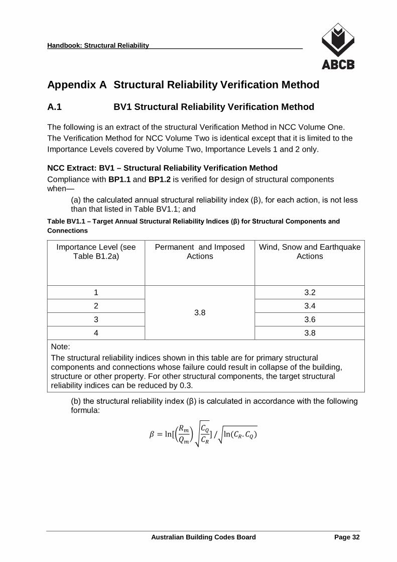
Appendix A Structural Reliability Verification Method
A.1 BV1 Structural Reliability Verification Method
The following is an extract of the structural Verification Method in NCC Volume One. The Verification Method for NCC Volume Two is identical except that it is limited to the Importance Levels covered by Volume Two, Importance Levels 1 and 2 only.
NCC Extract: BV1 – Structural Reliability Verification Method Compliance with BP1.1 and BP1.2 is verified for design of structural components when—
(a) the calculated annual structural reliability index (β), for each action, is not less than that listed in Table BV1.1; and
Table BV1.1 – Target Annual Structural Reliability Indices (β) for Structural Components and Connections
Importance Level (see Table B1.2a)
Permanent and Imposed Actions
Wind, Snow and Earthquake Actions
1 3.2
2 3.8
3.4
3 3.6
4 3.8
Note: The structural reliability indices shown in this table are for primary structural components and connections whose failure could result in collapse of the building, structure or other property. For other structural components, the target structural reliability indices can be reduced by 0.3.
(b) the structural reliability index (β) is calculated in accordance with the following formula:
𝛽𝛽 = ln[�𝑅𝑅𝑚𝑚𝑄𝑄𝑚𝑚
��𝐶𝐶𝑄𝑄𝐶𝐶𝑅𝑅
] /�ln (𝐶𝐶𝑅𝑅.𝐶𝐶𝑄𝑄)
Australian Building Codes Board Page 32

Handbook: Structural Reliability
where—
�𝑅𝑅𝑚𝑚𝑄𝑄𝑚𝑚
� =�𝛾𝛾𝜙𝜙� �
𝑅𝑅𝑚𝑚𝑅𝑅𝑛𝑛�
𝑄𝑄𝑚𝑚𝑄𝑄𝑛𝑛
𝐶𝐶𝑅𝑅 = 1 + 𝑉𝑉𝑅𝑅2
𝐶𝐶𝑄𝑄 = 1 + 𝑉𝑉𝑄𝑄2 where— CQ = correction factor for action; and CR = correction factor for resistance; and Qm = mean action; and Qn = nominal design action; and Rm = mean resistance; and Rn = nominal design resistance; and VQ = coefficient of variation with respect to action; and VR = coefficient of variation with respect to resistance; and Φ = capacity factor; and γ = load factor; and
c) the action models for calculation of the structural reliability index are determined in accordance with Table BV1.2; and
d) the resistance model for the structural component is established after taking into account variability due to material properties, fabrication and construction processes, and structural modelling.
Table BV1.2 – Action Models
Importance Level (See Table B1.2a)
Permanent Action
Imposed Action
Wind Action Snow Action
Earthquake Action Non-
cyclonic Cyclonic
Qm VQ Qm VQ Qm VQ Qm VQ Qm VQ Qm VQ
1 1.00 0.10 0.50 0.43 0.41 0.52 0.21 0.79 0.32 0.57 0.072 1.97
2 1.00 0.10 0.50 0.43 0.34 0.52 0.18 0.79 0.30 0.57 0.054 1.97
3 1.00 0.10 0.50 0.43 0.32 0.52 0.16 0.79 0.28 0.57 0.042 1.97
4 1.00 0.10 0.50 0.43 0.30 0.52 0.14 0.79 0.27 0.57 0.036 1.97
Australian Building Codes Board Page 33
Handbook: Structural Reliability
Appendix B Derivation of the Action Models
B.1 Introduction
This Appendix describes the derivation of the action models presented in Section 4 of this Handbook. The models, in general, include two components:
(a) a factor to convert action into action effect; and (b) the intensity of the action.
The former is largely based on judgement and the latter on statistical data. Lognormal distribution has been assumed for all parameters for ease of combination. It is important to note the models (except for Permanent Action) were established based on a reference time period of one year. Thus the resulting reliability indices are also for a one year time reference.
B.2 Permanent Action (Section 4.1)
The sources of uncertainties regarding permanent action include:
(a) variability in densities; (a) variability in dimensions; and (b) variability due to the designers’ estimates.
The uncertainties are generally regarded as small in comparison to other kinds of action. The probability of occurrence is almost certain and the variability with time is small. There is data on (a) and (b) but not (c), which is the larger source of uncertainty. Values for both parameters HG and g are based on judgement. There is little variation reported in literature from those assumed in this Handbook.
B.3 Imposed Action (Section 4.2)
Imposed action is classified in accordance with the intended use of certain areas of a building. AS/NZS 1170.1 lists the imposed actions to be used in design in accordance with the types of occupancy. Imposed action varies both in time and space. It has two components: a sustained component which includes the weights of furniture, equipment and an intermittent component which includes all other actions such as crowds of people and furniture stacking during renovation. Statistics for the two components of the imposed action are available for a number of occupancy types.
Different types of building occupancy result in different imposed action models. For the purpose of reliability assessment, it is desirable to have only one representative model
Australian Building Codes Board Page 34

Handbook: Structural Reliability
for imposed action. The statistical characteristics of office, residential and school buildings are sufficiently close to have a common model as the average of the three types of building occupancy. Factor H for permanent and imposed load is kept to the same value since the same structural modelling is used for both gravity types of load.
Joint Committee on Structural Safety (JCSS) reported a number of statistical data sets for different types of building occupancies (e.g. office, residential, schools, shops etc.). A number of models were established for different types of occupancies using JCSS parameters. A hybrid model was then established from the models for office, residential and school buildings to represent a typical Imposed Action.
B.4 Wind Action (Section 4.3)
Wind action on buildings is a function of a number of factors:
(a) the wind climate, (b) the building exposure, and (c) the building shape and dimension.
For Australian conditions, the wind climate is divided into two categories as defined in Australian Standard AS/NZS 1170.2:
• non-cyclonic, regions A and B; and
• cyclonic regions C and D.
The variable used to describe the wind climate is the wind speed. AS/NZS 1170.2:2011 Amendment 3 adopts a 0.2 second gust speed at a height of 10 metres in terrain category 2 as the basic wind speed.
Separate probabilistic wind speed models for region A, B, C and D were established using the 14 quartile values specified in AS/NZS 1170.2. Lognormal distribution was used for ease of combination with other parameters. Values for other factors are based on judgement or as given by JCSS.
The Mean and COV values for peak annual wind speed have been assessed from wind statistical records in accordance with the Importance Level requirements of the NCC and tabulated below:
Australian Building Codes Board Page 35
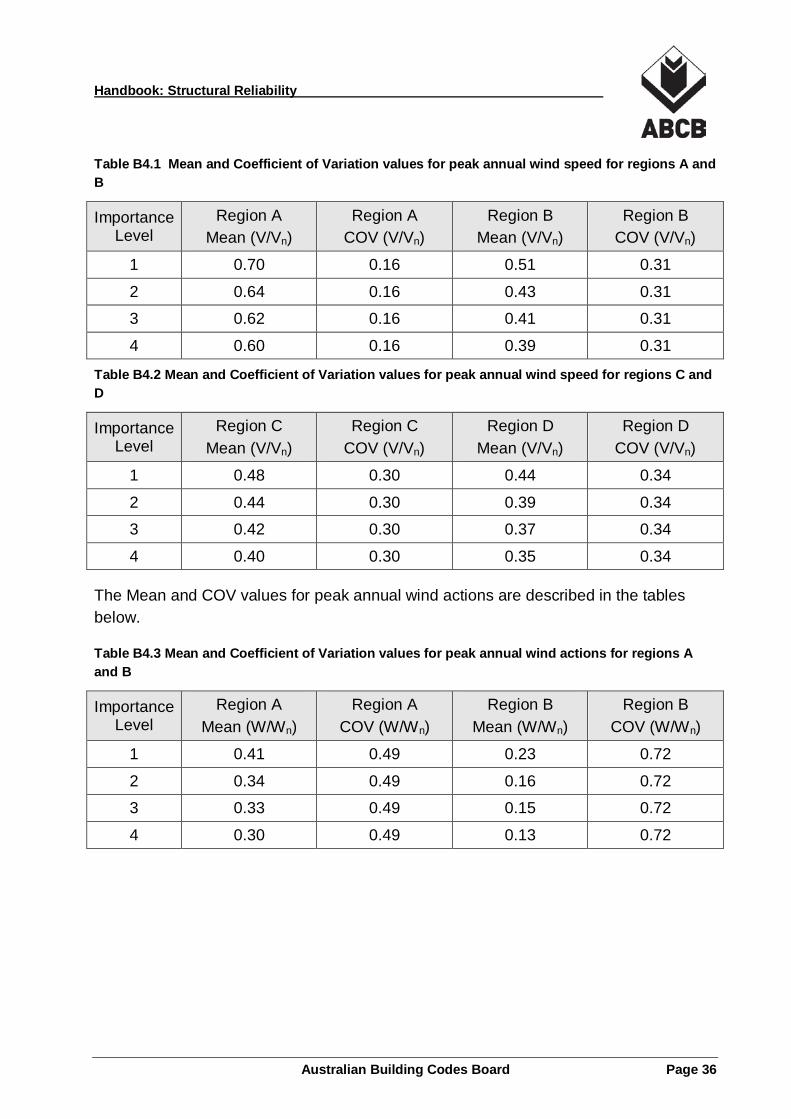
Handbook: Structural Reliability
Table B4.1 Mean and Coefficient of Variation values for peak annual wind speed for regions A and B
Importance Level
Region A Mean (V/Vn)
Region A COV (V/Vn)
Region B Mean (V/Vn)
Region B COV (V/Vn)
1 0.70 0.16 0.51 0.31
2 0.64 0.16 0.43 0.31
3 0.62 0.16 0.41 0.31
4 0.60 0.16 0.39 0.31
Table B4.2 Mean and Coefficient of Variation values for peak annual wind speed for regions C and D
Importance Level
Region C Mean (V/Vn)
Region C COV (V/Vn)
Region D Mean (V/Vn)
Region D COV (V/Vn)
1 0.48 0.30 0.44 0.34
2 0.44 0.30 0.39 0.34
3 0.42 0.30 0.37 0.34
4 0.40 0.30 0.35 0.34
The Mean and COV values for peak annual wind actions are described in the tables below.
Table B4.3 Mean and Coefficient of Variation values for peak annual wind actions for regions A and B
Importance Level
Region A Mean (W/Wn)
Region A COV (W/Wn)
Region B Mean (W/Wn)
Region B COV (W/Wn)
1 0.41 0.49 0.23 0.72
2 0.34 0.49 0.16 0.72
3 0.33 0.49 0.15 0.72
4 0.30 0.49 0.13 0.72
Australian Building Codes Board Page 36
Handbook: Structural Reliability
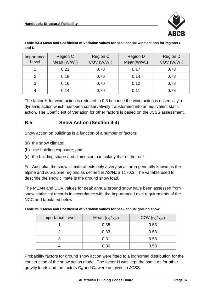
Table B4.4 Mean and Coefficient of Variation values for peak annual wind actions for regions C and D
Importance Level
Region C Mean (W/Wn)
Region C COV (W/Wn)
Region D Mean(W/Wn)
Region D COV (W/Wn)
1 0.21 0.70 0.17 0.78
2 0.18 0.70 0.14 0.78
3 0.16 0.70 0.12 0.78
4 0.14 0.70 0.11 0.78
The factor H for wind action is reduced to 0.8 because the wind action is essentially a dynamic action which has been conservatively transformed into an equivalent static action. The Coefficient of Variation for other factors is based on the JCSS assessment.
B.5 Snow Action (Section 4.4)
Snow action on buildings is a function of a number of factors:
(a) the snow climate; (b) the building exposure; and (c) the building shape and dimension particularly that of the roof.
For Australia, the snow climate affects only a very small area generally known as the alpine and sub-alpine regions as defined in AS/NZS 1170.3. The variable used to describe the snow climate is the ground snow load.
The MEAN and COV values for peak annual ground snow have been assessed from snow statistical records in accordance with the Importance Level requirements of the NCC and tabulated below:
Table B5.1 Mean and Coefficient of Variation values for peak annual ground snow
Importance Level Mean (sG/sGn) COV (sG/sGn)
1 0.35 0.53
2 0.33 0.53
3 0.31 0.53
4 0.30 0.53
Probability factors for ground snow action were fitted to a lognormal distribution for the construction of the snow action model. The factor H was kept the same as for other gravity loads and the factors CE and CF were as given in JCSS.
Australian Building Codes Board Page 37
Handbook: Structural Reliability
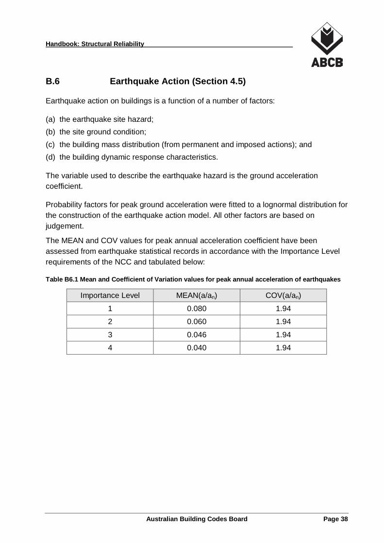
B.6 Earthquake Action (Section 4.5)
Earthquake action on buildings is a function of a number of factors:
(a) the earthquake site hazard; (b) the site ground condition; (c) the building mass distribution (from permanent and imposed actions); and (d) the building dynamic response characteristics.
The variable used to describe the earthquake hazard is the ground acceleration coefficient.
Probability factors for peak ground acceleration were fitted to a lognormal distribution for the construction of the earthquake action model. All other factors are based on judgement.
The MEAN and COV values for peak annual acceleration coefficient have been assessed from earthquake statistical records in accordance with the Importance Level requirements of the NCC and tabulated below:
Table B6.1 Mean and Coefficient of Variation values for peak annual acceleration of earthquakes
Importance Level MEAN(a/an) COV(a/an)
1 0.080 1.94
2 0.060 1.94
3 0.046 1.94
4 0.040 1.94
Australian Building Codes Board Page 38

Handbook: Structural Reliability
References Wang & Pham ‘Sampling factors for prototype testing of structures’ Australian Journal of Structural Engineering Vol.12, No2, 2012
Standards Australia, ‘AS/NZS 1170:2002 Structural design actions’ Standards Australia
Wang C. ‘An investigation on structural reliability Verification Method Final Report’ Feb 2014
International Standard Organisations, ISO 2394:1998, ‘General principles on reliability of structures’
Joint Committee on Structural Safety (JCSS) - 2000 ‘Probabilistic Model Code Part 1 – Basis of Design’
Australian Building Codes Board Page 39


