250.2 Definition
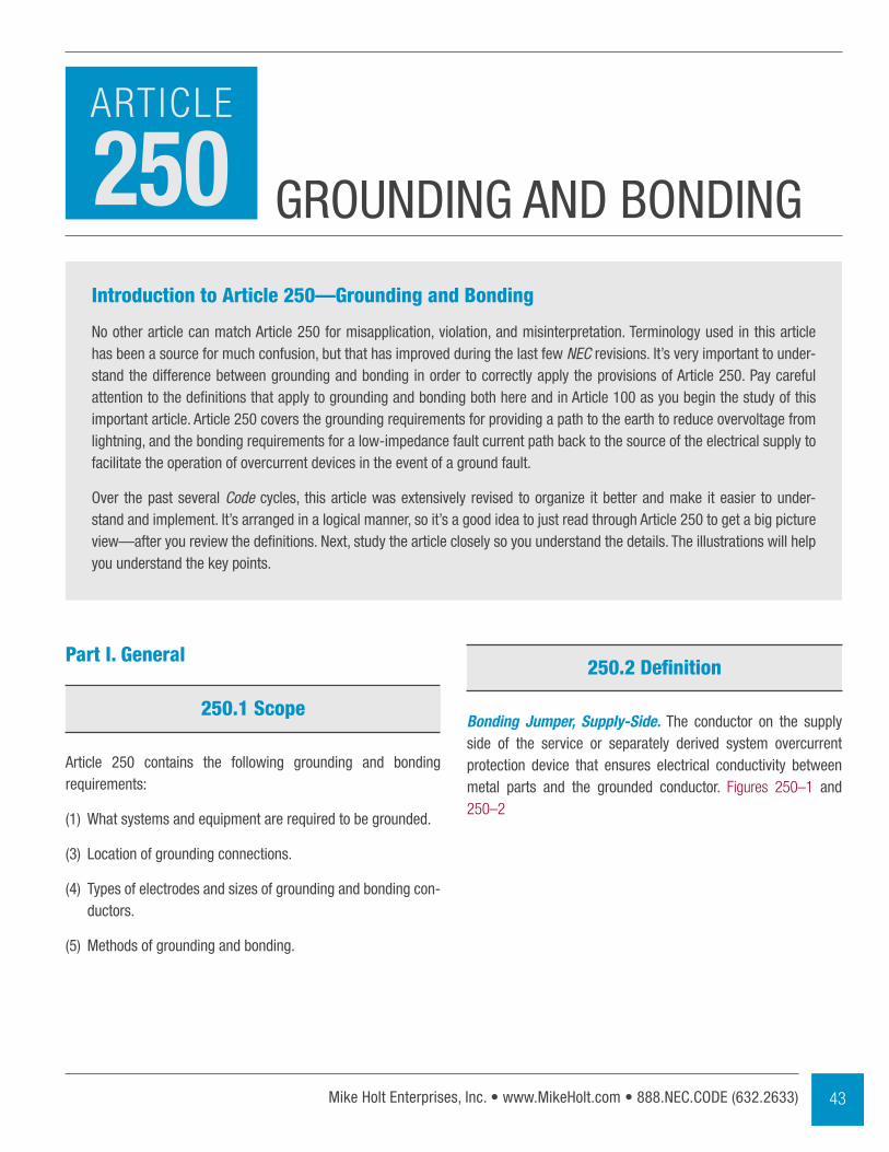
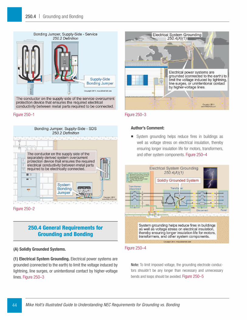
Bonding Jumper, Supply-Side. The conductor on the supply side of the service or separately derived system overcurrent protection device that ensures electrical conductivity between metal parts and the grounded conductor. Figures 250–1 and 250–2
Part I. General
250.1 Scope
Article 250 contains the following grounding and bonding requirements:
(1) What systems and equipment are required to be grounded.
(3) Location of grounding connections.
(4) Types of electrodes and sizes of grounding and bonding con-ductors.
(5) Methods of grounding and bonding.
Introduction to Article 250—Grounding and Bonding
No other article can match Article 250 for misapplication, violation, and misinterpretation. Terminology used in this article has been a source for much confusion, but that has improved during the last few NEC revisions. It’s very important to under-stand the difference between grounding and bonding in order to correctly apply the provisions of Article 250. Pay careful attention to the definitions that apply to grounding and bonding both here and in Article 100 as you begin the study of this important article. Article 250 covers the grounding requirements for providing a path to the earth to reduce overvoltage from lightning, and the bonding requirements for a low-impedance fault current path back to the source of the electrical supply to facilitate the operation of overcurrent devices in the event of a ground fault.
Over the past several Code cycles, this article was extensively revised to organize it better and make it easier to under-stand and implement. It’s arranged in a logical manner, so it’s a good idea to just read through Article 250 to get a big picture view—after you review the definitions. Next, study the article closely so you understand the details. The illustrations will help you understand the key points.
43Mike Holt Enterprises, Inc. • www.MikeHolt.com • 888.NEC.CODE (632.2633)
grOuNDINg AND BONDINg
ARTICLE
250
Author’s Comment:
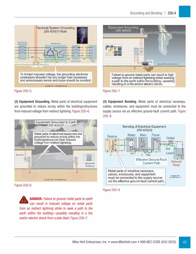
� System grounding helps reduce fires in buildings as well as voltage stress on electrical insulation, thereby ensuring longer insulation life for motors, transformers, and other system components. Figure 250–4
Note: To limit imposed voltage, the grounding electrode conduc-tors shouldn’t be any longer than necessary and unnecessary
bends and loops should be avoided. Figure 250–5
250.4 General Requirements for Grounding and Bonding
(A) Solidly Grounded Systems.
(1) Electrical System Grounding. Electrical power systems are grounded (connected to the earth) to limit the voltage induced by lightning, line surges, or unintentional contact by higher-voltage lines. Figure 250–3
Figure 250–1
Figure 250–2
Figure 250–3
Figure 250–4
Mike Holt’s Illustrated Guide to Understanding NEC Requirements for Grounding vs. Bonding44
250.4 | Grounding and Bonding
(3) Equipment Bonding. Metal parts of electrical raceways, cables, enclosures, and equipment must be connected to the supply source via an effective ground-fault current path. Figure 250–8
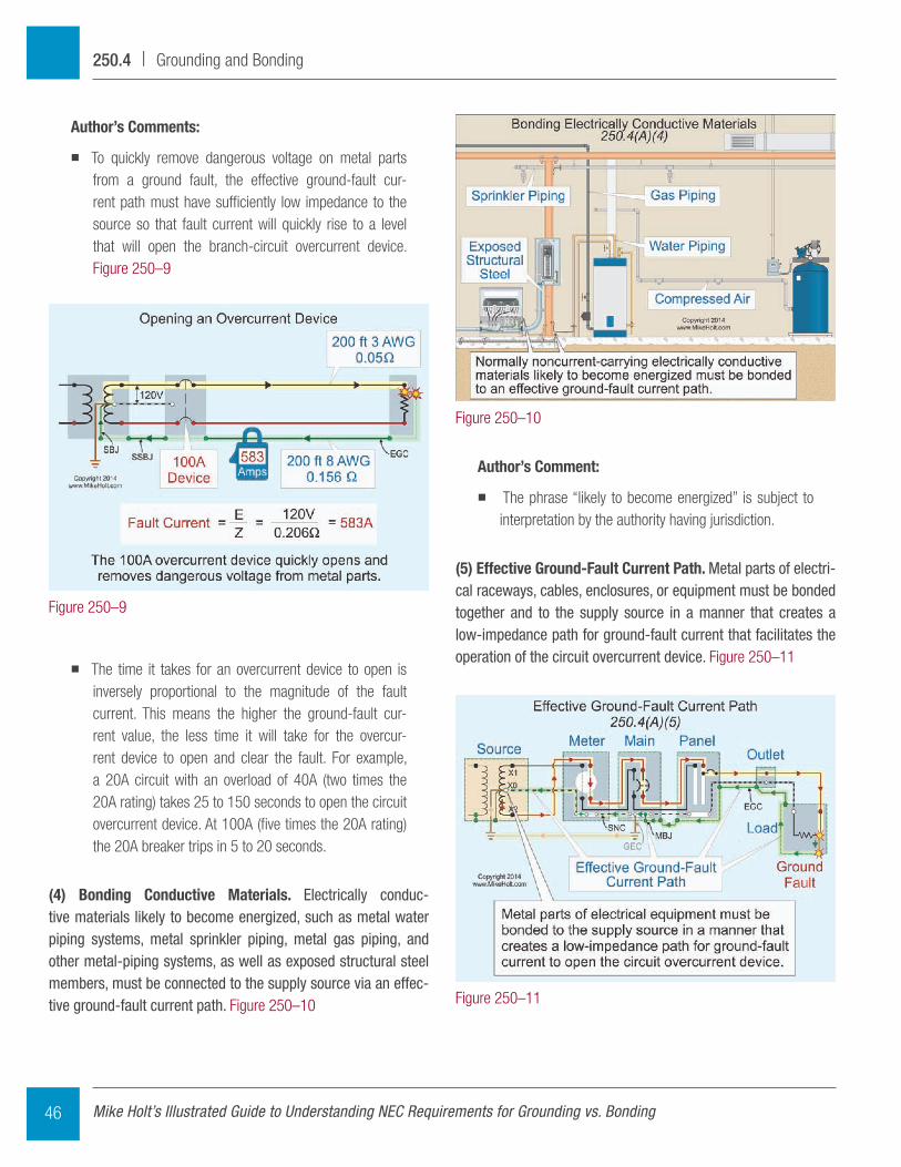
(2) Equipment Grounding. Metal parts of electrical equipment are grounded to reduce arcing within the buildings/structures from induced voltage from indirect lightning. Figure 250–6
DANGER: Failure to ground metal parts to earth can result in induced voltage on metal parts
from an indirect lightning strike to seek a path to the earth within the building—possibly resulting in a fire and/or electric shock from a side-flash. Figure 250–7
Figure 250–5
Figure 250–6
Figure 250–7
Figure 250–8
45Mike Holt Enterprises, Inc. • www.MikeHolt.com • 888.NEC.CODE (632.2633)
Grounding and Bonding | 250.4
Author’s Comment:
� The phrase “likely to become energized” is subject to interpretation by the authority having jurisdiction.
(5) Effective Ground-Fault Current Path. Metal parts of electri-cal raceways, cables, enclosures, or equipment must be bonded together and to the supply source in a manner that creates a low-impedance path for ground-fault current that facilitates the operation of the circuit overcurrent device. Figure 250–11
Author’s Comments:
� To quickly remove dangerous voltage on metal parts from a ground fault, the effective ground-fault cur-rent path must have sufficiently low impedance to the source so that fault current will quickly rise to a level that will open the branch-circuit overcurrent device. Figure 250–9
� The time it takes for an overcurrent device to open is inversely proportional to the magnitude of the fault current. This means the higher the ground-fault cur-rent value, the less time it will take for the overcur-rent device to open and clear the fault. For example, a 20A circuit with an overload of 40A (two times the 20A rating) takes 25 to 150 seconds to open the circuit overcurrent device. At 100A (five times the 20A rating) the 20A breaker trips in 5 to 20 seconds.
(4) Bonding Conductive Materials. Electrically conduc-tive materials likely to become energized, such as metal water piping systems, metal sprinkler piping, metal gas piping, and other metal-piping systems, as well as exposed structural steel members, must be connected to the supply source via an effec-tive ground-fault current path. Figure 250–10
Figure 250–9
Figure 250–10
Figure 250–11
Mike Holt’s Illustrated Guide to Understanding NEC Requirements for Grounding vs. Bonding46
250.4 | Grounding and Bonding
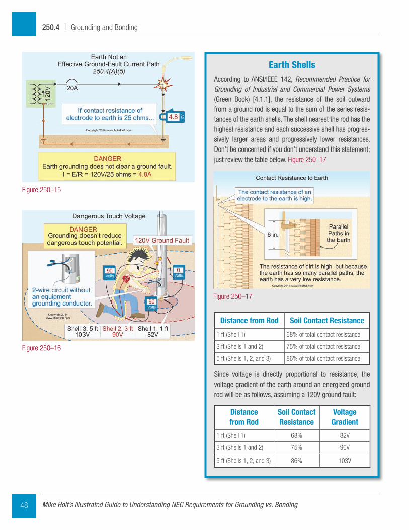
Question: What’s the maximum fault current that can flow through the earth to the power supply from a 120V ground fault to metal parts of a light pole without an equipment grounding conductor that’s grounded (connected to the earth) via a ground rod having a contact resistance to the earth of 25 ohms? Figure 250–14
(a) 4.80A (b) 20A (c) 40A (d) 100A
Answer: (a) 4.80A
I = E/RI = 120V/25 ohmsI = 4.80A
DANGER: Because the contact resistance of an electrode to the earth is so high, very little fault
current returns to the power supply if the earth is the only fault current return path. Figure 250–15
Result—the circuit overcurrent device won’t open and all metal parts associated with the electrical instal-lation, metal piping, and structural building steel will become and remain energized. Figure 250–16
Author’s Comment:
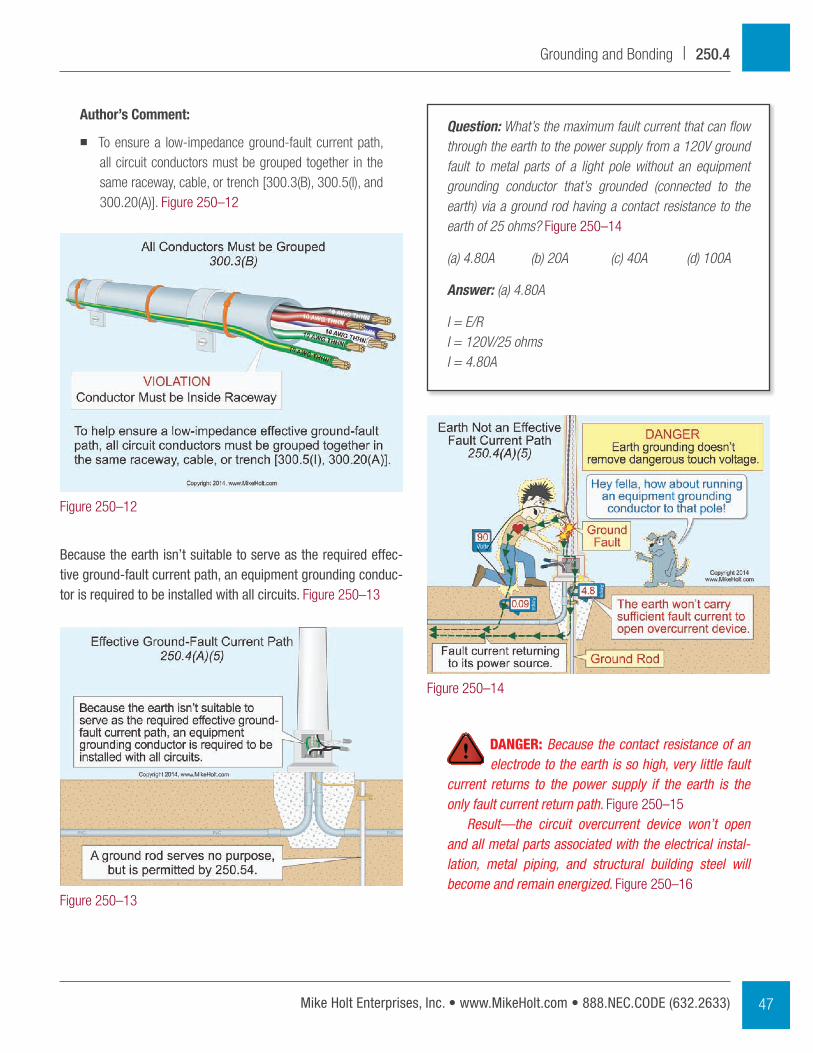
� To ensure a low-impedance ground-fault current path, all circuit conductors must be grouped together in the same raceway, cable, or trench [300.3(B), 300.5(I), and 300.20(A)]. Figure 250–12
Because the earth isn’t suitable to serve as the required effec-tive ground-fault current path, an equipment grounding conduc-tor is required to be installed with all circuits. Figure 250–13
Figure 250–12
Figure 250–13
Figure 250–14
47Mike Holt Enterprises, Inc. • www.MikeHolt.com • 888.NEC.CODE (632.2633)
Grounding and Bonding | 250.4
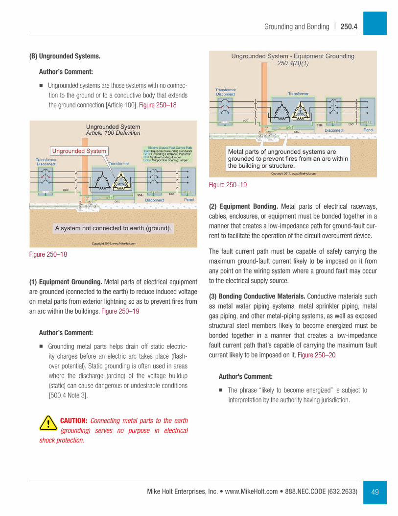
Earth ShellsAccording to ANSI/IEEE 142, Recommended Practice for Grounding of Industrial and Commercial Power Systems (green Book) [4.1.1], the resistance of the soil outward from a ground rod is equal to the sum of the series resis-tances of the earth shells. The shell nearest the rod has the highest resistance and each successive shell has progres-sively larger areas and progressively lower resistances. Don’t be concerned if you don’t understand this statement; just review the table below. Figure 250–17
Distance from Rod Soil Contact Resistance
1 ft (Shell 1) 68% of total contact resistance
3 ft (Shells 1 and 2) 75% of total contact resistance
5 ft (Shells 1, 2, and 3) 86% of total contact resistance
Since voltage is directly proportional to resistance, the voltage gradient of the earth around an energized ground rod will be as follows, assuming a 120V ground fault:
Distance from Rod
Soil Contact Resistance
Voltage Gradient
1 ft (Shell 1) 68% 82V
3 ft (Shells 1 and 2) 75% 90V
5 ft (Shells 1, 2, and 3) 86% 103V
Figure 250–16
Figure 250–15
Figure 250–17
Mike Holt’s Illustrated Guide to Understanding NEC Requirements for Grounding vs. Bonding48
250.4 | Grounding and Bonding
(2) Equipment Bonding. Metal parts of electrical raceways, cables, enclosures, or equipment must be bonded together in a manner that creates a low-impedance path for ground-fault cur-rent to facilitate the operation of the circuit overcurrent device.
The fault current path must be capable of safely carrying the maximum ground-fault current likely to be imposed on it from any point on the wiring system where a ground fault may occur to the electrical supply source.
(3) Bonding Conductive Materials. Conductive materials such as metal water piping systems, metal sprinkler piping, metal gas piping, and other metal-piping systems, as well as exposed structural steel members likely to become energized must be bonded together in a manner that creates a low-impedance fault current path that’s capable of carrying the maximum fault current likely to be imposed on it. Figure 250–20
Author’s Comment:
� The phrase “likely to become energized” is subject to interpretation by the authority having jurisdiction.
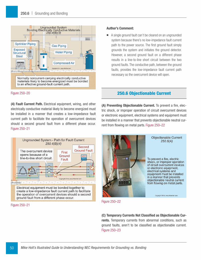
(B) Ungrounded Systems.
Author’s Comment:
� Ungrounded systems are those systems with no connec-tion to the ground or to a conductive body that extends the ground connection [Article 100]. Figure 250–18
(1) Equipment Grounding. Metal parts of electrical equipment are grounded (connected to the earth) to reduce induced voltage on metal parts from exterior lightning so as to prevent fires from an arc within the buildings. Figure 250–19
Author’s Comment:
� Grounding metal parts helps drain off static electric-ity charges before an electric arc takes place (flash-over potential). Static grounding is often used in areas where the discharge (arcing) of the voltage buildup (static) can cause dangerous or undesirable conditions [500.4 Note 3].
CAUTION: Connecting metal parts to the earth (grounding) serves no purpose in electrical
shock protection.
Figure 250–18
Figure 250–19
49Mike Holt Enterprises, Inc. • www.MikeHolt.com • 888.NEC.CODE (632.2633)
Grounding and Bonding | 250.4
Author’s Comment:
� A single ground fault can’t be cleared on an ungrounded system because there’s no low-impedance fault current path to the power source. The first ground fault simply grounds the system and initiates the ground detector. However, a second ground fault on a different phase results in a line-to-line short circuit between the two ground faults. The conductive path, between the ground faults, provides the low-impedance fault current path necessary so the overcurrent device will open.
250.6 Objectionable Current
(A) Preventing Objectionable Current. To prevent a fire, elec-tric shock, or improper operation of circuit overcurrent devices or electronic equipment, electrical systems and equipment must be installed in a manner that prevents objectionable neutral cur-rent from flowing on metal parts. Figure 250–22
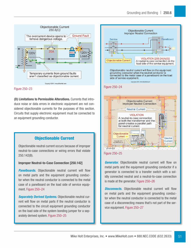
(C) Temporary Currents Not Classified as Objectionable Cur-rents. Temporary currents from abnormal conditions, such as ground faults, aren’t to be classified as objectionable current. Figure 250–23
(4) Fault Current Path. Electrical equipment, wiring, and other electrically conductive material likely to become energized must be installed in a manner that creates a low-impedance fault current path to facilitate the operation of overcurrent devices should a second ground fault from a different phase occur. Figure 250–21
Figure 250–20
Figure 250–21Figure 250–22
Mike Holt’s Illustrated Guide to Understanding NEC Requirements for Grounding vs. Bonding50
250.6 | Grounding and Bonding
Generator. Objectionable neutral current will flow on metal parts and the equipment grounding conductor if a generator is connected to a transfer switch with a sol-idly connected neutral and a neutral-to-case connection is made at the generator. Figure 250–26
Disconnects. Objectionable neutral current will flow on metal parts and the equipment grounding conduc-tor when the neutral conductor is connected to the metal case of a disconnecting means that’s not part of the ser-vice equipment. Figure 250–27
(D) Limitations to Permissible Alterations. Currents that intro-duce noise or data errors in electronic equipment are not con-sidered objectionable currents for the purposes of this section. Circuits that supply electronic equipment must be connected to an equipment grounding conductor.
Figure 250–23
Objectionable Current
Objectionable neutral current occurs because of improper neutral-to-case connections or wiring errors that violate 250.142(B).
Improper Neutral-to-Case Connection [250.142]
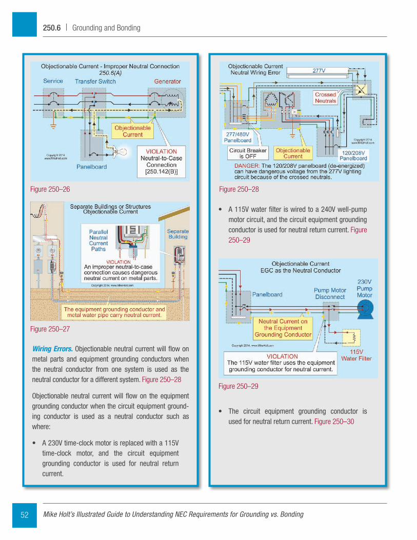
Panelboards. Objectionable neutral current will flow on metal parts and the equipment grounding conduc-tor when the neutral conductor is connected to the metal case of a panelboard on the load side of service equip-ment. Figure 250–24
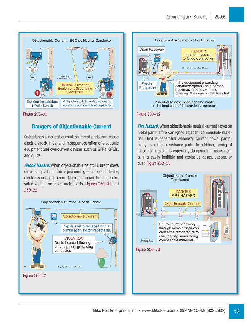
Separately Derived Systems. Objectionable neutral cur-rent will flow on metal parts if the neutral conductor is connected to the circuit equipment grounding conductor on the load side of the system bonding jumper for a sep-arately derived system. Figure 250–25
Figure 250–24
Figure 250–25
51Mike Holt Enterprises, Inc. • www.MikeHolt.com • 888.NEC.CODE (632.2633)
Grounding and Bonding | 250.6
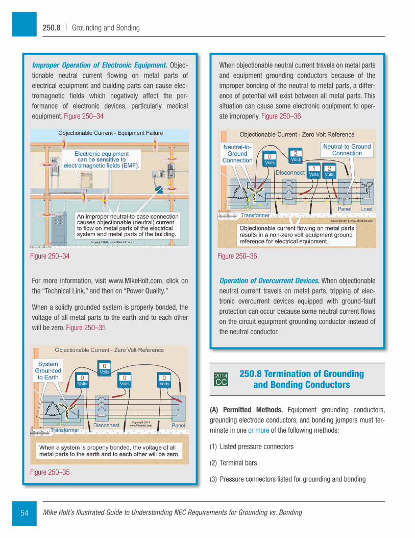
• A 115V water filter is wired to a 240V well-pump motor circuit, and the circuit equipment grounding conductor is used for neutral return current. Figure 250–29
• The circuit equipment grounding conductor is used for neutral return current. Figure 250–30
Wiring Errors. Objectionable neutral current will flow on metal parts and equipment grounding conductors when the neutral conductor from one system is used as the neutral conductor for a different system. Figure 250–28
Objectionable neutral current will flow on the equipment grounding conductor when the circuit equipment ground-ing conductor is used as a neutral conductor such as where:
• A 230V time-clock motor is replaced with a 115V time-clock motor, and the circuit equipment grounding conductor is used for neutral return current.
Figure 250–26 Figure 250–28
Figure 250–29
Figure 250–27
Mike Holt’s Illustrated Guide to Understanding NEC Requirements for Grounding vs. Bonding52
250.6 | Grounding and Bonding
Fire Hazard. When objectionable neutral current flows on metal parts, a fire can ignite adjacent combustible mate-rial. Heat is generated whenever current flows, partic-ularly over high-resistance parts. In addition, arcing at loose connections is especially dangerous in areas con-taining easily ignitible and explosive gases, vapors, or dust. Figure 250–33
Dangers of Objectionable Current
Objectionable neutral current on metal parts can cause electric shock, fires, and improper operation of electronic equipment and overcurrent devices such as gFPs, gFCIs, and AFCIs.
Shock Hazard. When objectionable neutral current flows on metal parts or the equipment grounding conductor, electric shock and even death can occur from the ele-vated voltage on those metal parts. Figures 250–31 and 250–32
Figure 250–30
Figure 250–33
Figure 250–32
Figure 250–31
53Mike Holt Enterprises, Inc. • www.MikeHolt.com • 888.NEC.CODE (632.2633)
Grounding and Bonding | 250.6
When objectionable neutral current travels on metal parts and equipment grounding conductors because of the improper bonding of the neutral to metal parts, a differ-ence of potential will exist between all metal parts. This situation can cause some electronic equipment to oper-ate improperly. Figure 250–36
Operation of Overcurrent Devices. When objectionable neutral current travels on metal parts, tripping of elec-tronic overcurrent devices equipped with ground-fault protection can occur because some neutral current flows on the circuit equipment grounding conductor instead of the neutral conductor.
Improper Operation of Electronic Equipment. Objec-tionable neutral current flowing on metal parts of electrical equipment and building parts can cause elec-tromagnetic fields which negatively affect the per-formance of electronic devices, particularly medical equipment. Figure 250–34
For more information, visit www.MikeHolt.com, click on the “Technical Link,” and then on “Power Quality.”
When a solidly grounded system is properly bonded, the voltage of all metal parts to the earth and to each other will be zero. Figure 250–35
Figure 250–36Figure 250–34
Figure 250–35
250.8 Termination of Grounding and Bonding Conductors
(A) Permitted Methods. Equipment grounding conductors, grounding electrode conductors, and bonding jumpers must ter-minate in one or more of the following methods:
(1) Listed pressure connectors
(2) Terminal bars
(3) Pressure connectors listed for grounding and bonding
Mike Holt’s Illustrated Guide to Understanding NEC Requirements for Grounding vs. Bonding54
250.8 | Grounding and Bonding


