
GEOPHYSICAL SURVEYS FOR
ASSISTING IN DETERMINING THE
GROUND WATER RESOURCES
KAUPULEHU AREA OF NORTH KONA
ISLAND OF HAW All
Blackhawk Geometries Project Number 9936KSB
Prepared For:
KAMEHAMEHA SCHOOLS BISHOP ESTATE
I
I
I
I
I
I
I
I
I
I
I
I
I
I
I
I
I
I
I
BLACKHAWK GEOMETRICS
301 Commercial Road, Suite 8, Golden, Colorado, 80401, USA
Tel: (303) 278-8700 Fax: (303) 278-078.9
www.blackhawkgeo.com
��©§:U��fDJ AUG 1 8 1999
99215KSB
August 16, 1999
Manabu Tagomori, P .E. W t R M TOM NANCE a er esources anager WAT£R R£SOURC Kamehameha Schools Bernice Pauahi Bishop Estatl £NGfNRRJNG
567 South King Street Honolu.lu, Hawaii 96813
Ph (808) 523-.6200 Fax (808)524-2069
Re: TDEM Surveys on KSBE Property in Kaupulehu, North Kona, Hawaii Blackhawk Geometries Project Number 9936KSB
Dear Manabu:
_GS
_LT
--'f.((TG
JOB
Enclosed are three copies of our final report fot the KaUpulehU project. The report contains TDEM data takeiJ. by Blackhawk from three different investigations (1990, 1993, and 1999) on KSBE property ill the North Kona District, of Hawaii. A copy of the report has been sent to Tom Nance.
We appreciated the opportunity to work with you again on this project. lfKSBE has 3,1;1y oth�r need for geophysical surveying or consultation, we would be pleased to provide assistance. If
you h�ve any questions, please do not hesitate to call.
Sincerely, BLACKHAWK GEOMETRICS
�"/#� ��iio� Senior Geologist
RB�lm
Enclosures
cc: Tom Nance
--�-
� GEOPHYSICAL SURVEYS FOR ASSISTING IN DETERMINING THE
GROUND WATER RESOURCES KAUPULEHU AREA OF NORTH KONA
ISLAND OF HAWAII
Blackhawk Geometries Project Number 9936KSB
Prepared For: KAMEHAMEHA SCHOOLS BISHOP ESTATE
567 South King Street Honolulu, Hawaii 96813
808-523-6200 • Fax 808-524-2069
Prepared By: BLACKHAWK GEOMETRICS, INC.
301 Commercial Road, Suite 8
Golden, Colorado 80401 303-278-8700 • Fax 303-278-0789
August16, 1999
�-��-fri ·t 11&&11.

TABLE OF CONTENTS
1.0 INTRODUCTION 3
2.0 DATA ACQUISITION AND LOGISTICS 4
3.0 DATA PROCESSING 6
4.0 INTERPRETATION RESULTS 7
4.1 GENERAL 7 4.2 GEOELECTRIC CROSS SECTIONS 8 4.3 HYDROGEOLOGIC INTERPRETATION 9
5.0 CONCLUSIONS ANO RECOMMENDATIONS 11
REFERENCES 12
Appendix A- Technical Note - TDEM Principles
Appendix B - TDEM Soundings
2
�//
I
I
I
I
I
I
I
I
I
I
I
I
I
I
I
I
I
I
I
1.0 INTRODUCTION
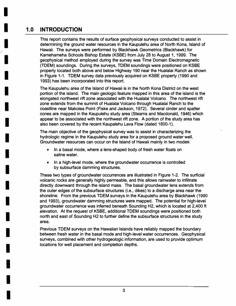
This report contains the results of surface geophysical surveys conducted to assist in determining the ground water resources in the Kaupulehu area of North Kona, Island of
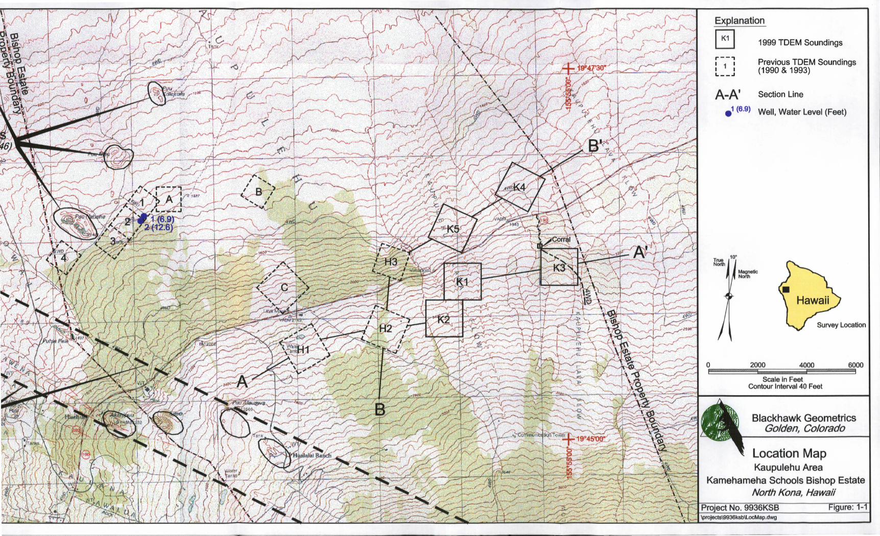
Hawaii. The surveys were performed by Blackhawk Geometries (Blackhawk) for Kamehameha Schools Bishop Estate (KSBE) from July 28 to August 1, 1999. The geophysical method employed during the survey was Time Domain Electromagnetic (TDEM) soundings. During the surveys, TDEM soundings were positioned on KSBE property located both above and below Highway 190 near the Hualalai Ranch as shown in Figure 1-1. TDEM survey data previously acquired on KSBE property ( 1990 and 1993) has been incorporated into this report.
The Kaupulehu area of the Island of Hawaii is in the North Kona District on the west portion of the island. The main geologic feature mapped in this area of the island is the elongated northwest rift zone associated with the Hualalai Volcano. The northwest rift zone extends from the summit of Hualalai Volcano through Hualalai Ranch to the coastline near Makolea Point (Fiske and Jackson, 1972). Several cinder and spatter cones are mapped in the Kaupulehu study area (Stearns and Macdonald, 1946) which appear to be associated with the northwest rift zone. A portion of the study area has also been covered by the recent Kaupalehu Lava Flow (dated 1800-1).
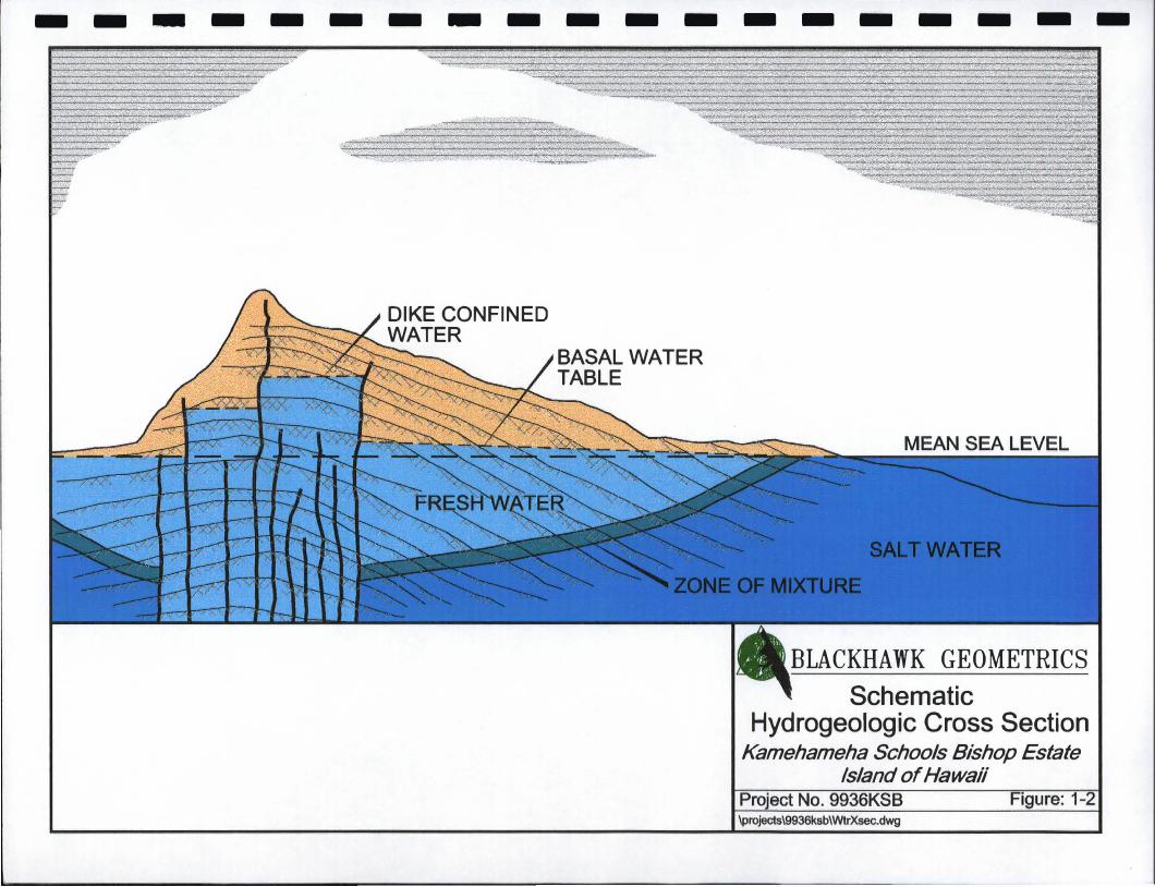
The main objective of the geophysical survey was to assist in characterizing the hydrologic regime in the Kaupulehu study area for a proposed ground water well. Groundwater resources can occur on the Island of Hawaii mainly in two modes:
• In a basal mode, where a lens-shaped body of fresh water floats on saline water.
• In a high-level mode, where the groundwater occurrence is controlled by subsurface damming structures.
These two types of groundwater occurrences are illustrated in Figure 1-2. The surficial volcanic rocks are generally highly permeable, and this allows rainwater to infiltrate directly downward through the island mass. The basal groundwater lens extends from the outer edges of the subsurface structures (i.e., dikes) to a discharge area near the shoreline. From the previous TDEM surveys in the Kaupulehu area by Blackhawk (1990 and 1993), groundwater damming structures were mapped. The potential for high-level groundwater occurrence was inferred beneath Sounding H2, which is located at 2,400 ft elevation. At the request of KSBE, additional TDEM soundings were positioned both north and east of Sounding H2 to further define the subsurface structures in the study area.
Previous TDEM surveys on the Hawaiian Islands have reliably mapped the boundary between fresh water in the basal mode and high-level water occurrences. Geophysical surveys, combined with other hydrogeologic information, are used to provide optimum locations for well placement and completion depths.
3
en
C)
&::
:0
&::
:::1
0
C/)
�
w
Q
t-
&::
=o
&::
:::1
0
C/)
�
w-
e�
t-
<»
cn..
.::
:sOI!S
.Qo
>
m
�m
a.
.:::.
,..-
-.,
: �
:
L-
--'
Q)
&::
�
&::
0
t5
Q)
C/)
-------------------
DIKE CONFINED WATER
BASAL WATER TABLE
�.. "�' �.c:c, _..._: '- ..C.,· •••• �; ......_. ·:." �·!:,�
BLACKHAWK GEOMETRICS
Schematic Hydrogeologic Cross Section
Kamehameha Schools Bishop Estate Island of Hawaii
I DATA ACQUISITION AND LOGISTICS
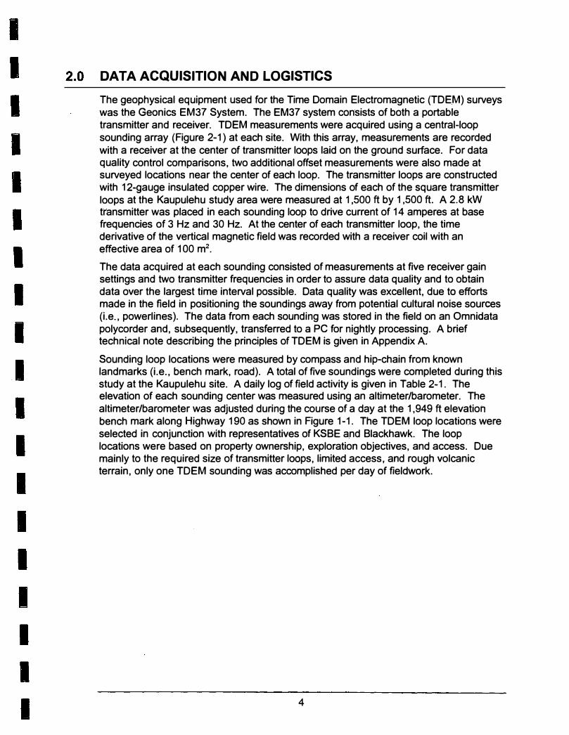
The geophysical equipment used for the Time Domain Electromagnetic (TDEM) surveys was the Geonics EM37 System. The EM37 system consists of both a portable transmitter and receiver. TDEM measurements were acquired using a central-loop sounding array (Figure 2-1) at each site. With this array, measurements are recorded with a receiver at the center of transmitter loops laid on the ground surface. For data quality control comparisons, two additional offset measurements were also made at surveyed locations near the center of each loop. The transmitter loops are constructed with 12-gauge insulated copper wire. The dimensions of each of the square transmitter loops at the Kaupulehu study area were measured at 1 ,500 ft by 1 ,500 ft. A 2.8 kW transmitter was placed in each sounding loop to drive current of 14 amperes at base frequencies of 3 Hz and 30 Hz. At the center of each transmitter loop, the time derivative of the vertical magnetic field was recorded with a receiver coil with an effective area of 100 m2•
The data acquired at each sounding consisted of measurements at five receiver gain settings and two transmitter frequencies in order to assure data quality and to obtain data over the largest time interval possible. Data quality was excellent, due to efforts made in the field in positioning the soundings away from potential cultural noise sources (i.e., powerlines). The data from each sounding was stored in the field on an Omnidata polycorder and, subsequently, transferred to a PC for nightly processing. A brief technical note describing the principles of TDEM is given in Appendix A.
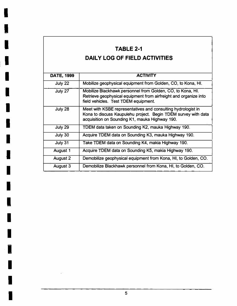
Sounding loop locations were measured by compass and hip-chain from known landmarks (i.e., bench mark, road). A total of five soundings were completed during this study at the Kaupulehu site. A daily log of field activity is given in Table 2-1. The elevation of each sounding center was measured using an altimeter/barometer. The altimeter/barometer was adjusted during the course of a day at the 1 ,949 ft elevation bench mark along Highway 190 as shown in Figure 1-1. The TDEM loop locations were selected in conjunction with representatives of KSBE and Blackhawk. The loop locations were based on property ownership, exploration objectives, and access. Due mainly to the required size of transmitter loops, limited access, and rough volcanic terrain, only one TDEM sounding was accomplished per day of fieldwork.
4
-
DATE, 1999
July 22
July 27
July 28
July 29
July 30
July 31
August 1
August 2
August 3 ------···-
TABLE 2 .. 1
DAILY LOG OF FIELD ACTIVITIES
ACTIVITY
Mobilize geophysical equipment from Golden, CO, to Kona, HI.
Mobilize Blackhawk personnel from Golden, CO, to Kona, HI. Retrieve geophysical equipment from airfreight and organize into field vehicles. Test TDEM equipment.
Meet with KSBE representatives and consulting hydrologist in Kona to discuss Kaupulehu project. Begin TDEM survey with data acquisition on Sounding K1, mauka Highway 190.
TDEM data taken on Sounding K2, mauka Highway 190.
Acquire TDEM data on Sounding K3, mauka Highway 190.
Take TDEM data on Sounding K4, makia Highway 190.
Acquire TDEM data on Sounding KS, makia Highway 190.
Demobilize geophysical equipment from Kona, HI, to Golden, CO.
Demobilize Blackhawk personnel from Kona, HI, to Golden, CO. --·----- -- - ---·-
5
- - -- -
I
i
.
i
'
RECEIVER COIL(Rx)�
NON-GROUNDED TRANSMITTER LOOP (Tx)-----.
RECEIVER__/' �«:�::�>:?·�.·,·:,-,· CONSOLE . - . . . .. _ ··:- � . � TRANSMITTER "' ,��'"-·· �.,, �.. •· · ' ' •. . . . , . .• . . . . ··c.
UNIT
Schematoc layoiUlt of TDE'M Centra�-loop Array with measurement locations of l'x a011d Rx
Figure: 2-1
Project No. 9936KSB
Projects\9936ksb\Tdem1.cdr

I
I
I
I
I
I
I
I
I
I
I
I
I
I
I
I
I
I
I
3.0 DATA PROCESSING
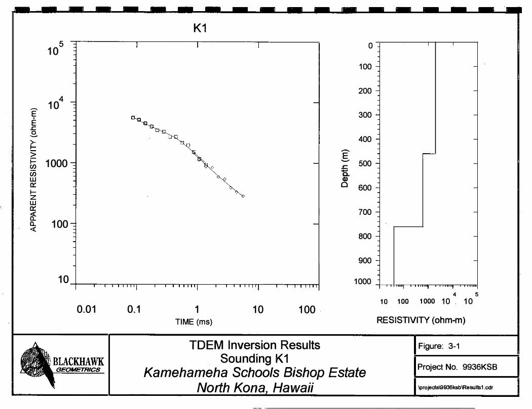
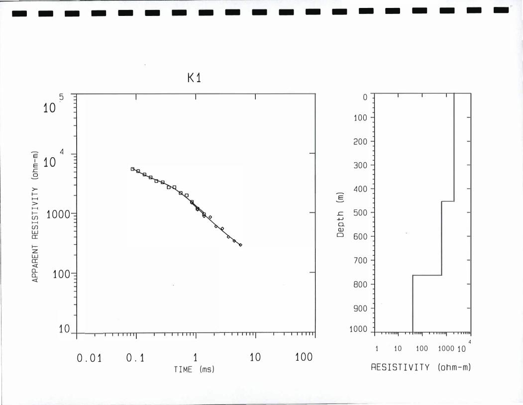
The TDEM field data acquired each day was transferred from the Omnidata polycorder to a PC. The first step in processing the TDEM data is to average the electromotive forces (emfs) recorded with the receiver. Next, the recordings made at different amplifier gains and frequencies were combined to give one transient decay curve with the program TEMIXXL (lnterpex L TO). With this program, voltages measured with the TDEM receiver are transformed into apparent resistivity verses time gate. The apparent resistivity curve is interpreted by inversion to a one-dimensional (1-D) geoelectric section that matches the observed decay curve.
The inversion program requires an initial estimate of the geoelectric section, including the number of layers and the thicknesses and resistivities of each of the layers. The program then adjusts these parameters so that the model curve converges to best fit the curve formed by the field data. The inversion program does not change the number of layers within the model, but allows all other parameters to change freely, or they can optionally be fixed constant. To determine the influence and best fit of the number of layers on the solution, separate inversions with different numbers of layers are run. The model with the fewest number of layers which best fits the data is used.
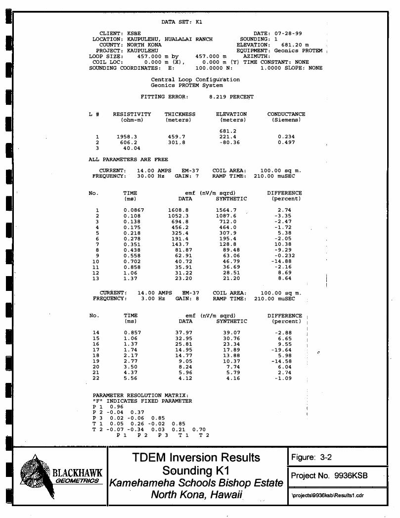
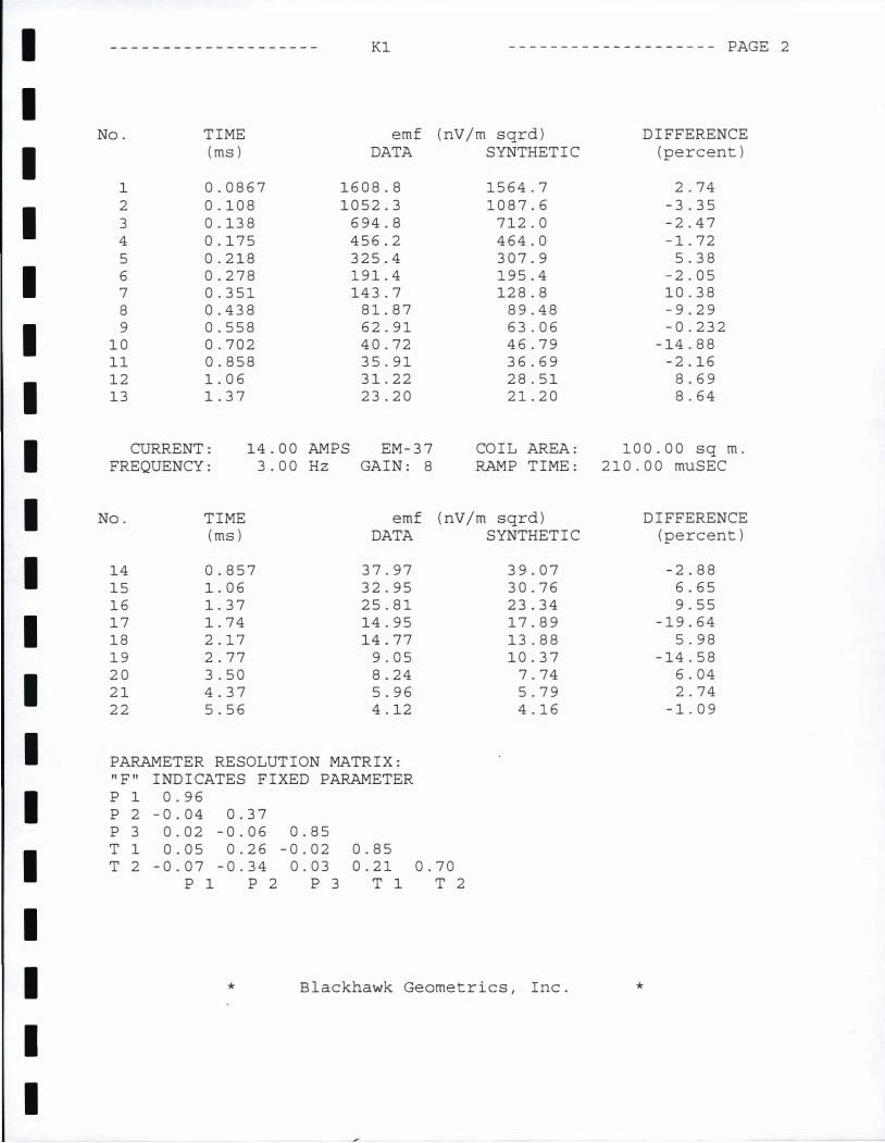
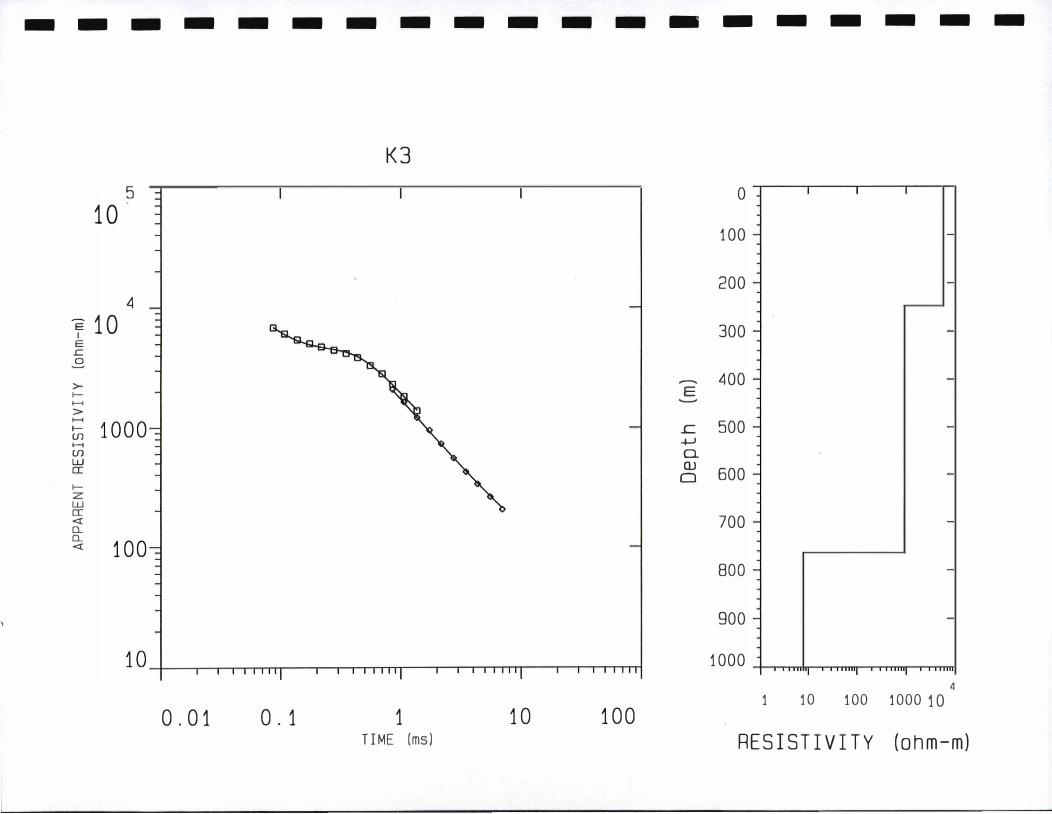
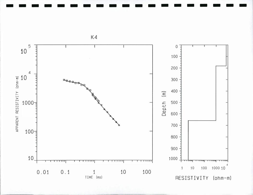
An example of the output of the inversion program for Sounding K1 is shown on Figures 3-1 and 3-2. Figure 3-1 shows the measured data points (in terms of apparent resistivity) superimposed on a solid line. The solid line represents the computed forward model of the geoelectric section shown on the right. Tabulated inversion parameters and results consisting of measured field data, computed data for best match solution, and inversion errors are given on Figure 3-2.
The apparent resistivity curves and data sheets for the five TDEM soundings taken during this survey are given in Appendix B.
6
5 � I 10
1
- 104
E � "' I
E .r:::. 0
-
I � > I- 1000 (/) (/) w 0::: I-z w 0:::
I � a. 100 <(
10 l I I I I I II if
0.01 0.1
I
K1
I
�
I I I I II if
1
0
TIME (ms)
0
I I I I I II If I
10
0
I 100
200
I 300
I 400
-
E -
500 s=. -
a. (I) 0 600
I 700
800
900
. . ..... I 1000
100
TDEM Inversion Results Sounding K1
Kamehameha Schools Bishop Estate North Kona, Hawaii
-
-
-
-
-
-
-
-
-
I I I
-
-
-
-
-
-
-
-
-
-
"'"I ""I ""'I ""
4 5 1 0 1 00 1 000 1 0 1 0
RESISTIVITY (ohm.-m)
, F,igure:. 3-1
Project No. 9936KSB
\projects\9936ksb\Resulls1.cdr
DATA SET: K1
CLIENT: KSBE DATE: 07-28-99
RANCH SOUNDING: 1 LOCATION: KAUPULEHU, HUALALAI COUNTY: NORTH KONA
PROJECT: KAUPULEHU LOOP SIZE: 457.000 m by
ELEVATION: 681.20 m EQUIPMENT: Geonics PROTEM 1
AZIMUTH: 457.000 m o.ooo m <Yl
100.0000 N: COIL LOC: 0.000 m (X),
SOUNDING COORDINATES: E: TIME CONSTANT: NONE
1.0000 SLOPE: NONE
Central Loop Configuration Geonics PROTEM System
FITTING ERROR:
L # RESISTIVITY THICKNESS {ohm-m) {meters)
1 1958.3 459.7
2 606.2 301.8
3 40.04
ALL PARAMETERS ARE FREE
CURRENT: 14.00 AMPS EM -37
FREQUENCY: 30.00 Hz GAIN: 7
No. TIME emf (ms) DATA
1 0.0867 1608.8
2 0.108 1052.3
3 0.138 694.8
4 0.175 456.2
5 0.218 325.4
6 0.278 191.4
7 0.351 143.7
8 0.438 81.87
9 0.558 62.91
10 0.702 40.72
11 0.858 35.91
12 1.06 31.22
13 1.37 23.20
CURRENT: 14.00 AMPS EM-37
FREQUENCY: 3.00 Hz GAIN: 8
No. TIME emf (ms) DATA
14 0.857 37.97
15 1. 06 32.95
16 1. 37 25.81
17 1. 74 14.95
18 2.17 14.77
19 2.77 9.05
20 3.50 8.24
21 4.37 5.96
22 5.56 4.12
PARAMETER RESOLUTION MATRIX: "F" INDICATES FIXED PARAMETER p 1 0.96
p 2 -0.04 0.37
8.219 PERCENT
ELEVATION {meters)
681.2
221.4
-80.36
COIL AREA: RAMP TIME:
(nV/m sqrd) SYNTHETIC
1564.7
1087.6
712.0
464.0
307.9
195.4
128.8
89.48
63.06
46.79
36.69
28.51
21.20
COIL AREA: RAMP TIME:
(nV/m sqrd) SYNTHETIC
39.07
30.76
23.34
17.89
13.88 10.37
7.74
5.79
4.16
p 3 0.02 -0.06
T 1 0.05 0.26
T 2 -0.07 - 0.34
p 1 p 2
0.85
-0.02
0.03
p 3
0.85
0.21
T 1
0.70
T 2
CONDUCTANCE (Siemens)
0.234
0.497
100.00 sq m. 210.00 muSEC
DIFFERENCE (percent)
2.74
-3.35
-2.47
-1.72
5.38
-2.05
10.38
-9.29
-0.232
-14.88
-2.16
8.69
8.64
100.00 sq m. 210.00 muSEC
DIFFERENCE (percent)
-2.88
6.65
9.55
-19.64 0
5.98
-14.58
6.04
2.74
-1.09
TDEM Inversion Results Figure: 3-2
Sounding K1
I Project No. 9936KSB
I Kamehameha Schools Bishop Estate North Kona, Hawaii \projects\9936ksb\Results1.cdr

I
I
I
I
I
I
I
I
I
I
I
I
I
I
I
I
I
I
I
4.0 INTERPRETATION RESULTS
4.1 General
The main objective of TDEM soundings is to derive the resistivity layering (geoelectric section) of the subsurface. The translation of resistivity layering into hydrologic information is generally accomplished by two methods. These include:
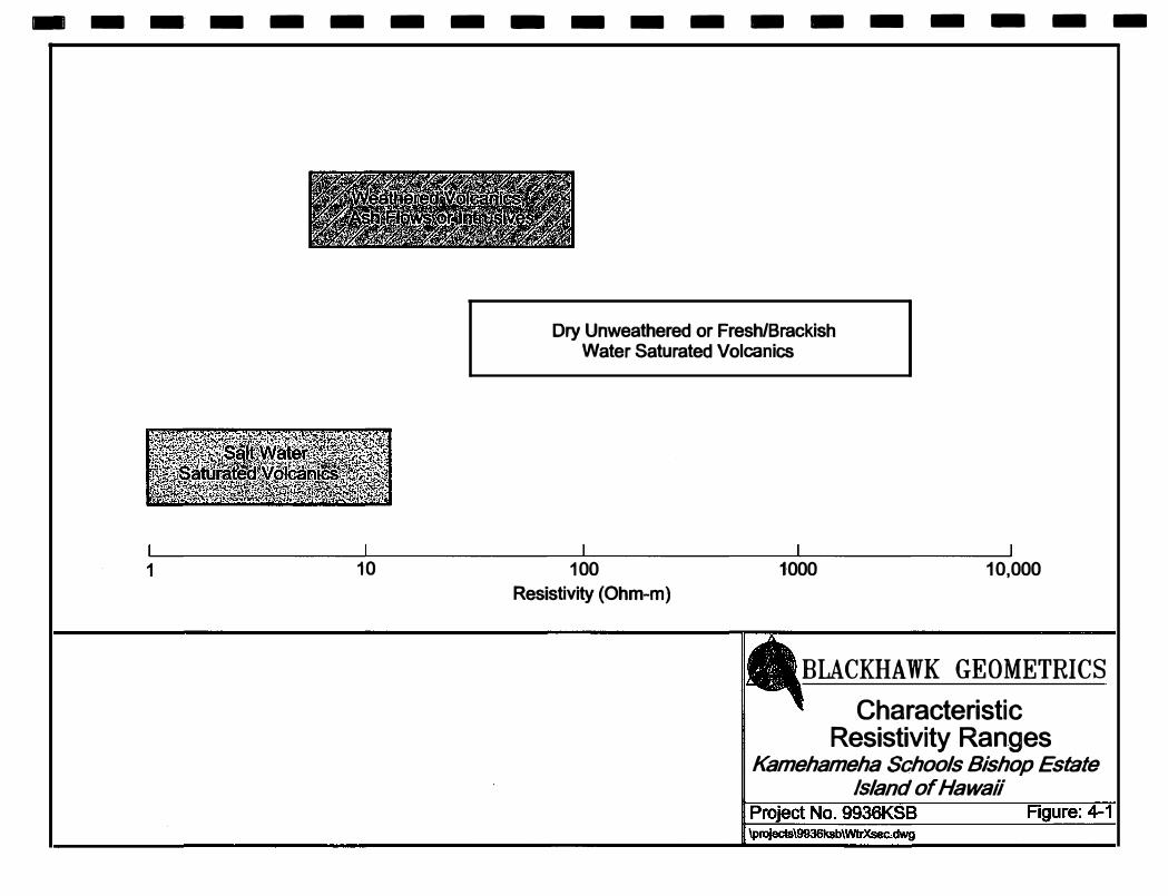
1) Using available knowledge about the relation between resistivity values and local hydrology. From more than 25 previous TDEM surveys on the Hawaiian Islands, it has been observed that volcanic rocks saturated with salt water exhibit resistivities typically less than 5 ohm-m. Conversely, volcanic rocks that are dry and unweathered or fresh water saturated, exhibit high resistivities (generally greater than 500 ohm-m). Weathered volcanics or ash flows and intrusives often exhibit intermediate resistivities (about 1 0 ohm-m to 100 ohm-m).
Applying this information, characteristic ranges of resistivities expected for local hydrogeologic units for the Kaupulehu study area are shown in Figure 4-1. It should be noted that some overlap in resistivity values occur. In these cases, other factor"$ are used to infer the geologic/hydrologic unit in question. For example, a loW resistivity unit (i.e., less than 10 ohm-m) occurring at ari elevation above sea level is assumed to be caused by either weathered rock units or intrusives (i.e., dikes) instead of salt water saturated formations.
2) Another method is to calibrate the geophysical interpretation at a welL There were two wells (1 and 2) used for comparison to the 1990 TDEM data. The location of the two wells is between Soundings 1 and 2. The two wells have static water levels (head) of 6.9 ft and 12.6 ft, respectively. The large difference in head over the short distance (about 100ft) can be explained by possible geologic structures (Le., dikes, faults) that affect groundwater flow or possible error in head measurements. The TDEM soundings show a complicated area near the two wells with geologic structures being inferred between Soundings 2 and A. The calculated head from Sounding A is about 10.8 ft, which appears reasonable for this area.
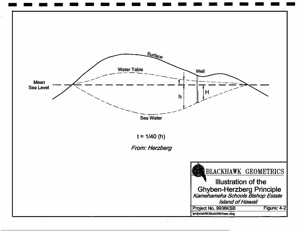
Where a very conductive layer (less than 5 ohm-m) is detected below sea level in the TDEM measurement, the layer is interpreted to be caused by salt water saturated volcanics. Static fresh water levels can be calculated from these soundings by using the Ghyben-Herzberg relation as illustrated in Figure 4.2. The Ghyben..,Herzberg relation states that for every 1 ft of fresh water above sea level, approximately 4 0ft of fresh water will exist below sea level. However, hydrostatic equilibrium is assumed for these measurements, and this relation is not expected to apply to soundings in close proximity to major geologic structures (i.e., rift zones, dikes) which can alter groundwater flow. Generally, rift zones contain vertical dikes and faults, which can run parallel and subparallel to the main rift orientation for hundreds of feet within a central rift corridor. Intersecting dikes are common in rift zones, and groundwater can become compartmentalized between the dikes. Rift zones may also contain a series of cinder and spatter cones, which generally trend linearly away from a central volcano.
7

I
I
I
I
I
I
I
I
I
I
I
I
I
I
I
I
I
I
I
4.2 Geoelectric Cross Sections
The results of the inversion of the individual TDEM soundings are the1-D resistivity layering as a function of depth. The TDEM results from individual soundings can be linked together to produce a 2-D geoelectric cross-section along a survey transect. The geoelectric cross-section can be correlated to geologic units by comparison with available geologic information. The locations of soundings from previous TDEM surveys (1990 and 1993) on KSBE property have been incorporated into this report. From these combined data sets, two new geoelectric cross-sections were constructed. The location map of the Kaupulehu area and the directions of the geoelectric cross sections are shown on Figure 1-1.
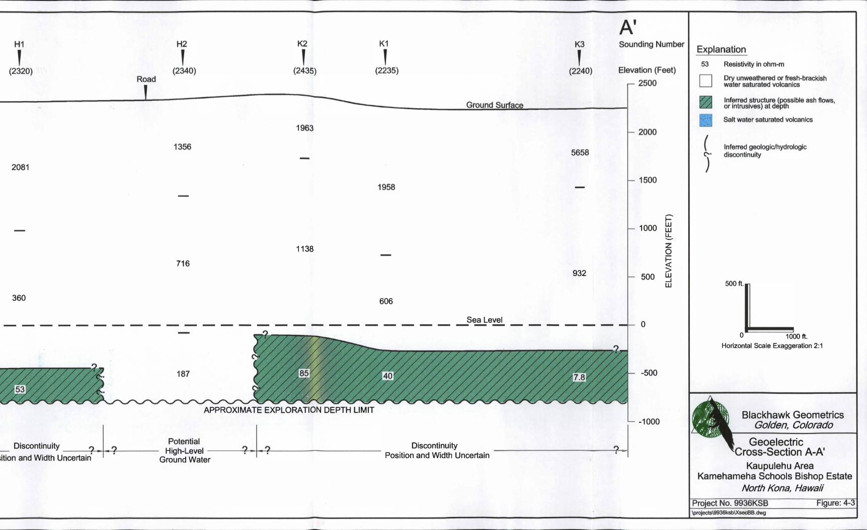
Geoelectric Cross-Section A·A'
Figure 4-3 shows the results of five TDEM soundings presented as a west to east trending geoelectric cross-section (A-A'), in which layers that exhibit similar resistivity values have been linked together.
The interpreted geoelectric section from the five soundings consists of three layers. The uppermost layer of each sounding, with resistivities ranging from about 1356 ohmm to 5658 ohm-m, is interpreted to represent dry unweathered volcanics above mean sea level (msl). The second layer in the cross-section exhibits resistivities from about 360 ohm-m to 1138 ohm-m. It is also interpreted as unweathered volcanics above msl; and where it occurs below msl, it is expected to be saturated with fresh-brackish basal water. The third layer (green) in the section, beneath Soundings H1, K2, K1, and K3, exhibits an intermediate to low resistivity ranging from about 85 ohm-m to 7.8 ohm-m. The resistivity values of the third layer are interpreted to be influenced by lateral discontinuities (i.e., dikes, faults). Because of rapid lateral variations in resistivities between Soundings H2, K2, K1, and K3, the interpreted resistivity stratification may not represent true formation resistivities. The exact position and width of the discontinuous layers is uncertain due to TDEM data density. Since the sea water interface was not interpreted beneath any of the soundings, the elevation of the groundwater table cannot be calculated by the Ghyben-Herzberg relation. However, because the top of the intermediate resistivity layer (53 ohm-m) beneath Sounding H1 is interpreted to be about 450ft below msl, the potential for fresh w�ter occurring beneath Sounding H1 is good. The top of the low resistivity layer (7.8 ohmm) beneath Sounding K3 is interpreted to be about 250ft below msl, and a modest layer of fresh-brackish water may occur at this location.
Sounding H2 exhibits high resistivity values (187 ohm-m to 1356 ohm-m) throughout the effective exploration depth (about 750 ft below msl) of the data. This sounding is interpreted to be located between geologic/hydrologic structures observed on either side (Soundings H1 and K2). With the existing TDEM data density, the hydrogeologic boundaries are placed midway between the soundings, and the potential for high-level groundwater appears to exist beneath Sounding H2.
8
I
I
I
I
I
I
I
I
I
I
I
I
I
I
I
I
I
I
I
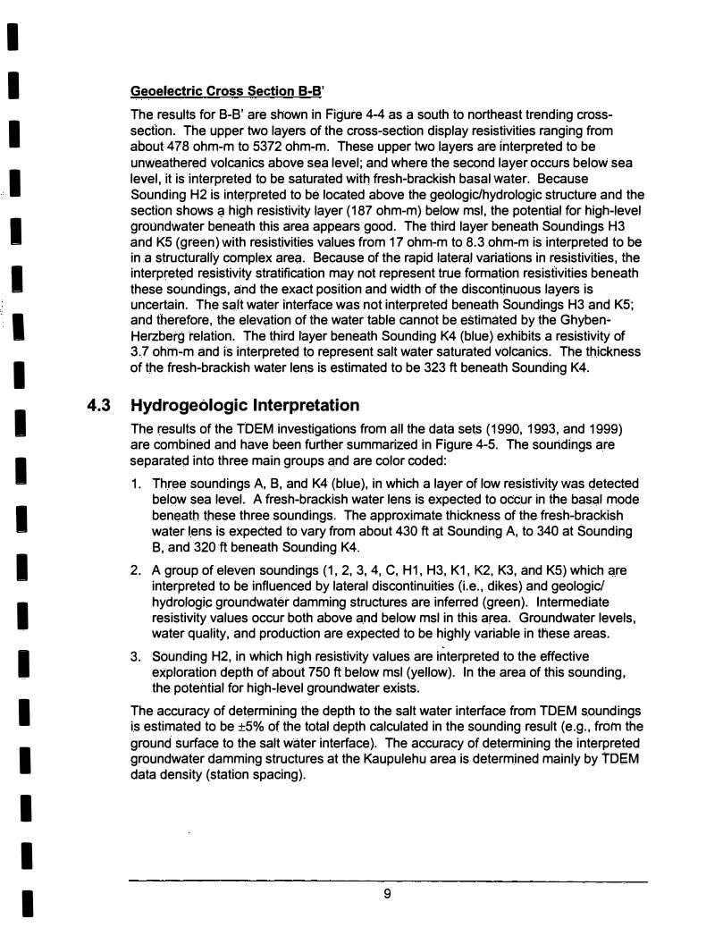
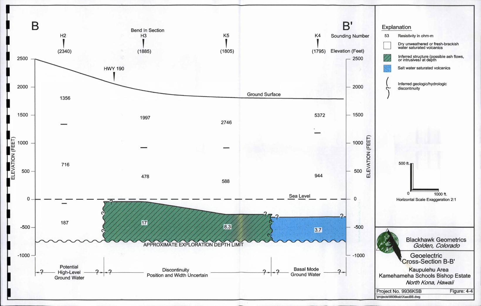
Geoelectric Cross Section 8-B'
The results for B-B' are shown in Figure 4-4 as a south to northeast trending crosssection. The upper two layers of the cross-section display resistivities ranging from about 478 ohm-m to 5372 ohm-m. These upper two layers are interpreted to be unweathered volcanics above sea level; and where the second layer occurs below sea level, it is interpreted to be saturated with fresh-brackish basal water. Because Sounding H2 is interpreted to be located above the geologic/hydrologic structure and the section shows a high resistivity layer (187 ohm-m) below msl, the potential for high-level groundwater beneath this area appears good. The third layer beneath Soundings H3 and K5 (green) with resistivities values from 17 ohm-m to 8.3 ohm-m is interpreted to be
in .a structurally complex area. Because of the rapid lateral variations in resistivities, the interpreted resistivity stratification may not represent true formation resistivities beneath these soundings, and the exact position and width of the discontinuous layers is uncertain. The sc;�lt water interface was not interpreted beneath Soundings H3 and K5;
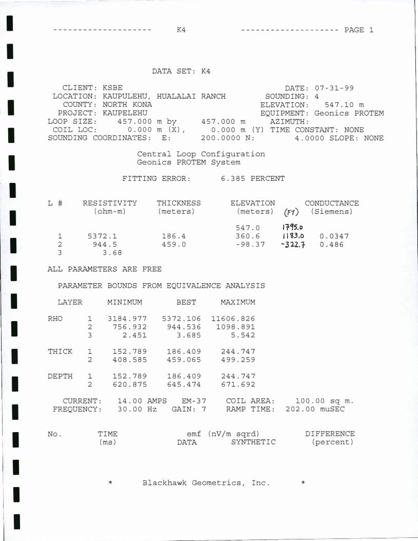
and therefore, the elevation of the water table cannot be estimated by the Ghyben• Herzberg relation. The third layer beneath Sounding K4 (blue) exhibits a resistivity of 3.7 ohm-m and is interpreted to represent salt water saturated volcanics. The thickness of the fresh-brackish water lens is estimated to be 323 ft beneath Sounding K4.
4.3 Hydrogeologic Interpretation
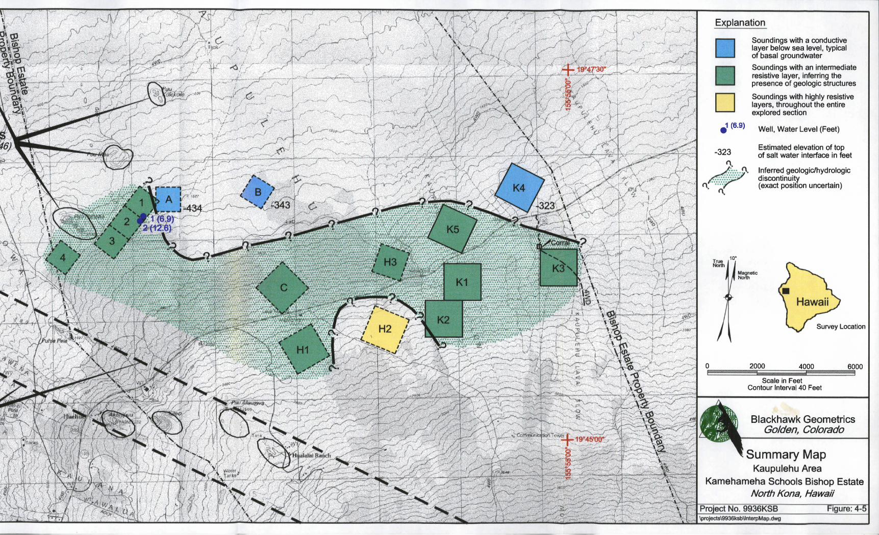
The results of the TDEM investigations from all the data sets (1990, 1993, and 1999) are combined and have been further summarized in Figure 4-5. The soundings are separated into three main groups and are color coded:
1. Three soundings A, B, and K4 (blue), in which a layer of low resistivity was detected below sea level. A fresh-brackish water lens is expected to occur in the basal mode ben�ath these three soundings. The approximate thickness of the fresh-brackish water lens is expected to vary from about 430 ft at Sounding A, to 340 at Sounding B, and 320 ft beneath Sounding K4.
2. A group of eleven soundings (1, 2, 3, 4, C, H1, H3, K1, K2, K3, and K5) which are interpreted to be influenced by lateral discontinuities (i.e., dikes) and geologic/ hydrologic groundwater damming structures are inferred (green). Intermediate resistivity values occur both above and below msl in this area. Groundwater levels, water quality, and production are expected to be highly variable in these areas.
3. Sounding H2, in which high resistivity values are interpreted to the effective exploration depth of about 750 ft below msl (yellow). In the area of this sounding, the potential for high-level groundwater exists.
The accuracy of determining the depth to the salt water interface from TDEM soundings is estimated to be ±5% ofthe total depth calculated in the sounding result (e.g., from the ground surface to the salt water interface). The accuracy of determining the interpreted groundwater damming structures at the Kaupulehu area is determined mainly by TDfi:M data density (station spacing).
9
I
I
I
I
I
I
I
I
I
I
I
I
I
I
I
I
I
I
I
From the summary map, the lower (makia) boundary of the inferred geologic/hydrologic discontinuity is placed upslope from Sounding 8 at about the 1520 ft elevation level. From there, it continues roughly along contour to the east, where it rapidly increases elevation (1900 ft above msl) upslope from Sounding K4. The exact cause of the rapid increase upslope near Sounding K4 is unknown, but it appears to be structure (i.e., dike) related. The inland (mauka) boundary of the inferred discontinuity is approximately placed above Sounding H3 and between Soundings H1, and H2; and H2, and K2. The position of the inland boundary appears to place Sounding H2 above inferred geologic/ hydrologic groundwater damming structures, which are roughly defined on three sides. The northwest rift zone from Hualalai Volcano appears to intersect the Kaupulehu area at a N 60° W bearing approximately above the Hualalai Ranch. This feature may have an affect on groundwater flow in the Kaupulehu area.
10
---·----------------
�������fit���"-�'lJ;� ���Jt-��.,���l:llll�"" . -�-�%� �-{�� , '''��·•" �v,��--,>>'�;��-f<'�
�;t' ����l�- .LU;.f"' -1'1 L�&�?By!f�� - v.. , ,% �!�.'ii'UAfi����� ��,;;;;r_,f I
Dry Unweathered or Fresh/Brackish Water Saturated Volcanics
1 10 100 1·000 10,000
Resistivity (Ohm-m)
BLACKHAWK GEOMETRICS I
Characteristic Resistivity Ranges
Kamehameha Schools Bishop Estate Island of Hawaii
----------------·---
Mean
Sea Level
Water Table ----------- --- -
hI -;;"}_�-��� � ---------"" ' "--- ' , ........................... ----- ------
Sea Water
t = 1/40 (h)
From: Herzberg
/
BLACKHAWK GEOMETRICS
Illustration of the Ghyben-Herzberg Principle
Kamehameha Schools Bishop Estate Island of Hawaii
360
_ Discontinuity ? .1. ? •ition and Width Uncertain
· ·
1138
716
606
Sea Level
APPROXIMATE EXPLORATION DEPTH LIMIT
Potential I High-Level ? .. . ?
Discontinuity
Ground Water Position and Width Uncertain
I
932 I I
') _ ;I
-.,_ w 1000 w LL -
z 0 .,_
� 500 w
_J I w
0
-500
-1000
500ft.
0 1000 ft.
Horizontal Scale Exaggeration 2:1
Blackhawk Geometries Golden, Colorado
Geoelectric ross-Section A-A'
Kaupulehu Area Kamehameha Schools Bishop Estate
North Kona, Hawaii
B Bend In Section B' H2 H3 K5 K4 Sounding Number
' ' ' ' (2340) (1885) (1805) (1795) Elevation (Feet)
2500 ------ r--- 2500 I HWY 190 I I
' � 2000 2000 � ----...._____ Ground Surface
1356
1500 � 1997 5372 � 1500
2746 �
--
- I-
tli 1000 1000 tl1 w - - LL LL --
z z
0 0
� 716 �· >
500 500 w w _J _J 478 944 w w
588
0-1-- ______ -=- ________________ Sealeve!.__ __ l 0
187 -500
-1000
~ Potential High-Level . Ground Water
? .I.? . .
' • · .· · ·:. ·.
· .· . . ·.
• •• ... 0 • •
Discontinuity ? I ? Basal Mode I Position and Width Uncertain · • • · Ground Water �
-500
-1000
Explanation
53
D . �
f··.::··ll
( ('·
)
Resistivity in ohm-m
Dry unweathered or fresh-brackish water saturated volcanics
Inferred structure (possible ash flows, or intrusives) at depth
Salt water saturated volcanics
Inferred geologic/hydrologic discontinuity
500ft.
0 1000 ft.
Horizontal Scale Exaggeration 2:1
Blackhawk Geometries Golden, Colorado
Geoelectric ���-Section B-B'
Kaupulehu Area Kamehameha Schools Bishop Estate
North Kona, Hawaii
0
Explanation
D fi (6.9)
-323
(\
10°
Soundings with a conductive layer below sea level, typical of basal groundwater
Soundings with an intermediate resistive layer, inferring the presence of geologic structures
Soundings with highly resistive layers, throughout the entire explored section
Well, Water Level (Feet)
Estimated elevation of top of salt water interface in feet
Inferred geologic/hydrologic discontinuity (exact position uncertain)
��etic
Survey Location
2000 4000 6000 � r,,,,,,,,,x,,,((////'1'////ffffH//1 pm!?''''"''''''W&.-'''''"'o/"1
Scale in Feet Contour Interval 40 Feet
Blackhawk Geometries Golden, Colorado
Summary Map Kaupulehu Area
Kamehameha Schools Bishop Estate
North Kana� Hawaii
I
I
I
I
I
I
I
I
I
I
I
I
I
I
I
I
I
I
I
5.0 CONCLUSIONS AND RECOMMENDATIONS
-- -- - --------
The results of the TDEM surveys ( 1990, 1993, and 1999) at the Kaupulehu area of North Kana, Hawaii, for KSBE are combined and shown in Figure 4-5. The data
indicate that beneath three soundings, a lens of basal mode fresh-brackish water
occurs. The thickest lens of potential fresh-brackish water resource is interpreted to
occur beneath Sounding A, and it is estimated to be 434 ft. Soundings 1, 2, and 3,
taken near Wells 1 and 2 (reported heads of 6.9 ft and 12.6 ft) showed intermediate
resistivity layers (28 ohm-m to 43 ohm-m) slightly below msl and are interpreted to be in an area of geologic structures. The calculated head from Sounding A is about 10.8 ft, and this appears to be reasonable in this structurally complicated area.
In a large area of the survey (beneath Soundings 1, 2, 3, 4, C, H 1, H3, K 1, K2, K3, and K5), subsurface structures (i.e., dikes, rift zone) are interpreted, and the groundwater regime is expected to be structurally complicated with groundwater yield and quality in this area being highly variable. The groundwater resources within areas controlled by geologic structures cannot be determined directly from the TDEM
sounding data.
Beneath Sounding H2, the potential for high-level groundwater is expected to exist. Groundwater damming structures are interpreted on three sides of Sounding H2; and therefore, this appears to be the best location for a high-level water occurrence.
The northwest rift zone (approximately positioned on Figure 4-5) from Hualalai Volcano appears to intersect the survey area at about a N 60° W bearing near Puu
Alauawa on the Hualalai Ranch. This geologic feature is expected to have an affect on the groundwater flow in this area.
To help confirm the position of the lower and upper inferred groundwater damming structure, additional TDEM sounding data should be taken in areas of sparse data density.
11
I
I
I
I
I
I
I
I
I
I
I
I
I
I
I
I
I
I
I
REFERENCES
1. Davis, S. N., DeWiest, R. J. M., 1966. Hydrogeology, ground water in igneous
rocks, pp. 333-343.
2. Fiske, R. S., and Jackson, E. D., 1972. Orientation and growth of Hawaiian volcanic
rifts: The effect of regional structure and gravitational stresses: Proceedings of the
Royal Society of London, ser. A. v. 329, pp. 299-326.
3. Langenheim, V.A.M., Clague, D.A., 1987. Stratigraphic framework of volcanic rocks of the Hawaiian Islands, Chap 1, Volcanism in Hawaii: U.S. Geological Survey Professional Paper 1350, Vol 1, pp. 61-63.
4. Stearns, H. T., Macdonald, G. A., 1946. Geology and ground-water resources of the Island of Hawaii, Hawaii Division of Hydrography Bulletin 9, pp. 137-149.
5. Wilt, M. J., 1991. Interpretation of time domain electromagnetic soundings near geologic contacts, Ph.D. Thesis, Lawrence Berkeley Laboratory, University of California Earth Sciences Division, pp. 185.
12
-------------------
K1
5 0 I I I
10 100 - -
200 - -
I I
4 � 10 j - I 300 - -
.c 0
�
>- 400 - -
I- �
I--I E
> ......_. r--
I--I
I- 1000 .r: 500 (f) ..j-1
- -
I--I
(f) 0.
w QJ
IT 0 600 - -
I-z w
I I IT 700 - -
<( 0...
100 0... <( ' ' 800 - -
900 - -
10 l I I I I I 1111 I I I I I 1111 I I I I I 1111 I I I I I I I
I 1000 "I "I "I
<1
1 10 100 1000 10 0.01 0. 1 1 10 100
TIME (ms) RESISTIVITY (ohm-m)

I
I
I
I
I
I
I
I
I
I
I
I
I
I
I
I
I
I
I
K1 -------------------- PAGE 1
DATA SET: K1
CLIENT: KSBE LOCATION: KAUPULEHU,
COUNTY: NORTH KONA PROJECT: KAUPULEHU
LOOP SIZE: 457.000
COIL LOC: 0.000
SOUNDING COORDINATES:
DATE: 07-28-99
HUALALAI RANCH SOUNDING: 1
m by m (X),
E:
457.000 m
ELEVATION: 681.20 m EQUIPMENT: Geonics PROTEM
AZIMUTH: 0.000 m (Y) TIME CONSTANT: NONE
100.0000 N: 1.0000 SLOPE: NONE
Central Loop Configuration Geonics PROTEM System
FITTING ERROR: 8.219 PERCENT
L #
1
2
3
RESISTIVITY (ohm-m)
1958.3
606.2
40.04
THICKNESS (meters)
459.7
301.8
ELEVATION (meters)
681.2
221.4
-80.36
ALL PARAMETERS ARE FREE
PARAMETER BOUNDS FROM EQUIVALENCE ANALYSIS
LAYER MINIMUM BEST MAXIMUM
RHO 1 1751.785 1958.312 2251.026
2 390.962
3 26.013
THICK 1 381.323
2 231.632
DEPTH 1 381.323
2 759.824
CURRENT: 14.00 AMPS FREQUENCY:
No. TIME (ms)
30.00 Hz
606.208 914.237
40.047 58.084
459.724 553.225
301.841 400.260
459.724 553.225
761.565 788.327
EM-37 COIL AREA: GAIN: 7 RAMP TIME:
emf (nV/m sqrd) DATA SYNTHETIC
'* Blackhawk Geometries, Inc.
CONDUCTANCE (FT) (Siemens)
2235.0 12,,'1 0. 234
-2,3., 0.497
100.00 sq m. 210.00 muSEC
*
DIFFERENCE (percent)
I
I
I
I
I
I
I
I
I
I
I
I
I
I
I
I
I
I
I
K1 -------------------- PAGE 2
No. TIME emf (nV /m sqrd) DIFFERENCE (ms) DATA SYNTHETIC (percent)
1 0.0867 1608.8 1564.7 2.74
2 0.108 1052.3 1087.6 -3.35
3 0.138 694.8 712.0 -2.47
4 0.175 456.2 464.0 -1.72
5 0.218 325.4 307.9 5.38
6 0.278 191.4 195.4 -2.05
7 0.351 143.7 128.8 10.38
8 0.438 81.87 89.48 -9.29
9 0.558 62.91 63.06 -0.232
10 0.702 40.72 46.79 -14.88
11 0.858 35.91 36.69 -2.16
12 1. 06 31.22 28.51 8.69
13 1. 37 23.20 21.20 8.64
CURRENT: 14.00 AMPS EM -37 COIL AREA: 100.00 sq m. FREQUENCY: 3.00 Hz GAIN: 8 RAMP TIME: 210.00 muSEC
No. TIME emf (nV/m sqrd) DIFFERENCE (ms) DATA SYNTHETIC (percent)
14 0.857 37.97 39.07 -2.88
15 1. 06 32.95 30.76 6.65
16 1. 37 25.81 23.34 9.55
17 1. 74 14.95 17.89 -19.64
18 2.17 14.77 13.88 5.98
19 2.77 9.05 10.37 -14.58
20 3.50 8.24 7.74 6.04
21 4.37 5.96 5.79 2.74
22 5.56 4.12 4.16 -1.09
PARAMETER RESOLUTION MATRIX: "F" INDICATES FIXED PARAMETER p 1 0.96
p 2 -0.04 0.37
p 3 0.02 -0.06 0.85
T 1 0.05 0.26 -0.02 0.85
T 2 -0.07 -0.34 0.03 0.21 0.70
p 1 p 2 p 3 T 1 T 2
* Blackhawk Geometries, Inc. *

-------------------
K2
5 0 I I I
10. 100 - -
- -
-I 200
I
- -� 10 4
� I 300 .c. 0
- -
�
� � >- 400 I- ...--..
1---l E >
- -
- -
1---l
10001 I- � l .c. 500 (f) � 1---l (f)
0.
w Cl.l
a: 0 600 I-z
- -
w
I I a: 700 <{ Q_
100 Q_
- -
<{ BOO
900 - -
"I 'I "I 10 1 I 1000
I I I I I 1111 I I I I I 1111 I I I I I 1111 I I I I I ll1
4
1 10 100 1000 10 0.01 0. 1 1 10 100
TIME (ms) RESISTIVITY (ohm-m)

I
I
I
I
I
'I
I
I
I
I
I
I
I
I
I
I
I
I
I
K2 -------------------- PAGE 1
DATA SET: K2
DATE: 07-29-99 CLIENT: KSBE LOCATION: KAUPULEHU,
COUNTY: NORTH KONA PROJECT: KAUPELEHU
HUALALAI RANCH SOUNDING: 2
ELEVATION: 742.20 m
LOOP SIZE: 457.000 m by 457.000 m EQUIPMENT: Geonics PROTEM
AZIMUTH: COIL LOC: 0.000 m (X),
E: 0.000 m (Y) TIME CONSTANT: NONE
SOUNDING COORDINATES: 100.0000 N: 2.0000 SLOPE: NONE
L #
1
2
3
Central Loop Configuration Geonics PROTEM System
FITTING ERROR: 4.678 PERCENT
RESISTIVITY (ohm-m)
1962.8
1137.7
85.17
THICKNESS (meters)
214.0
561.7
ELEVATION (meters)
742.2
528.1
-33.65
ALL PARAMETERS ARE FREE
PARAMETER BOUNDS FROM EQUIVALENCE ANALYSIS
LAYER MINIMUM BEST MAXIMUM
RHO 1 1652.091 1962.849 2618.626
2 910.438 1137.772 1392.325
3 71.507 85.175 102.957
THICK 1 165.629 214.081 322.136
2 467.413 561.773 617.284
DEPTH 1 165.629 214.081 322.136
2 764.885 775.855 794.511
CURRENT: 14.00 AMPS EM-37 COIL AREA: FREQUENCY:
No. TIME (ms)
*
30.00 Hz GAIN: 6 RAMP TIME:
emf (nV/m sqrd) DATA SYNTHETIC
Blackhawk Geometries, Inc.
----- ------------------------------
CONDUCTANCE (JT) (Siemens)
2�3S,o 1132,, 0.109
-Jio.'/ 0.493
100.00 sq m. 210.00 muSEC
*
DIFFERENCE (percent)
I
I
I
I
I
I
I
I
I
I
I·
I
I
I
I
I
I
I
I
I
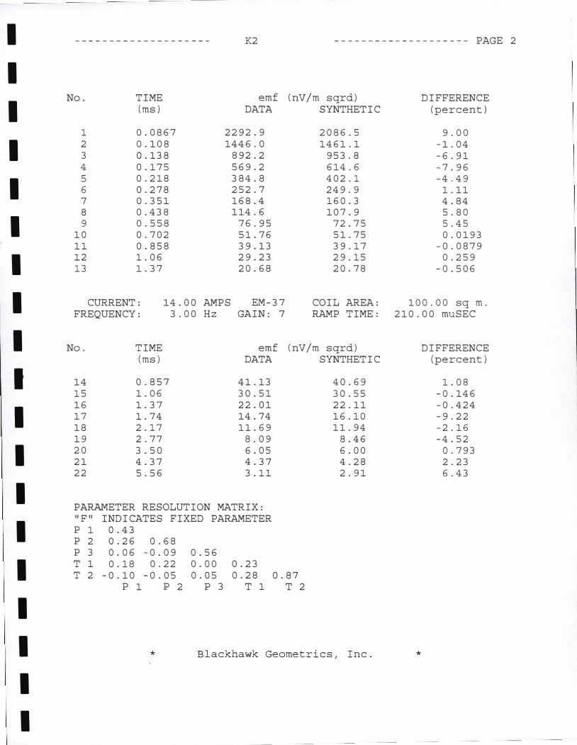
- - ---- - --- - - - -- - - - -- K2 -------------------- PAGE 2
No. TIME emf (nV /m sqrd) DIFFERENCE (ms) DATA SYNTHETIC (percent)
1 0.0867 2292.9 2086.5 9.00 2 0.108 1446.0 1461.1 -1.04 3 0.138 892.2 953.8 -6.91 4 0.175 569.2 614.6 -7.96 5 0.218 384.8 402.1 -4.49 6 0.278 252.7 249.9 1.11 7 0.351 168.4 160.3 4.84 8 0.438 114.6 107.9 5.80 9 0.558 76.95 72.75 5.45
10 0.702 51.76 51.75 0.0193 11 0.858 39.13 39.17 -0.0879 12 1. 06 29.23 29.15 0.259 13 1. 37 20.68 20.78 -0.506
CURRENT: 14.00 AMPS EM-37 COIL AREA: 100.00 sq m. FREQUENCY: 3.00 Hz GAIN: 7 RAMP TIME: 210.00 muSEC
No. TIME emf (nV /m sqrd) DIFFERENCE (ms) DATA SYNTHETIC (percent)
14 0.857 41.13 40.69 1. 08 15 1. 06 30.51 30.55 -0.146 16 1. 37 22.01 22.11 -0.424 17 1. 74 14.74 16.10 -9.22 18 2.17 11.69 11.94 -2.16 19 2.77 8.09 8.46 -4.52 20 3.50 6.05 6.00 0.793 21 4.37 4.37 4.28 2.23 22 5.56 3.11 2.91 6.43
PARAMETER RESOLUTION MATRIX: "F" INDICATES FIXED PARAMETER p 1 0.43 p 2 0.26 0.68 p 3 0.06 -0.09 0.56 T 1 0.18 0.22 0.00 0.23 T 2 -0.10 -0.05 0.05 0.28 0.87
p 1 p 2 p 3 T 1 T 2
* Blackhawk Geometries, Inc. *
-------------------
5
10
I
4
E: 10 I �
E .r: 0 �
j >-
f-1---i
> � 10001 f-z: w a:
I <t: ()_ ()_
100 <t:
...,
10 l
0.01
�-
0.1
K3
�
�
1 TIME (ms)
I
I
I
l I
I
I
10 100
..........
E
..c:
4--1
0.
QJ
0
0
100 -
200 -
300 -
400 -
500 -
600 -
700 -
BOO -
900 -
1000
1
I I I
1-
1-
-
-
-
-
-
-
-
"I '"'I ""I ....
4
10 100 1000 10
RESISTIVITY (ohm-m)
I
I
I
I
I
I
I
I
I
I
I
I
I
I
I
I
I
I
I
K3 -------------------- PAGE 1
DATA SET: K3
CLIENT: KSBE LOCATION: KAUPULEHU,
COUNTY: NORTH KONA PROJECT: KAUPELEHU
LOOP SIZE: 457.000 COIL LOC: 0.000
SOUNDING COORDINATES:
HUALALAI RANCH DATE: 07-30-99
SOUNDING: 3
m by m (X),
E:
ELEVATION: 682.80 m EQUIPMENT: Geonics PROTEM
457.000 m AZIMUTH: 0.000 m (Y) TIME CONSTANT: NONE
200.0000 N: 3.0000 SLOPE: NONE
Central Loop Configuration Geonics PROTEM System
FITTING ERROR: 2.372 PERCENT
L #
1 2 3
RESISTIVITY (ohm-m)
5657.9 931.8
7.79
THICKNESS (meters)
248.0 516.0
ELEVATION (meters)
682.7 434.7 -81.26
ALL PARAMETERS ARE FREE
PARAMETER BOUNDS FROM EQUIVALENCE ANALYSIS
LAYER MINIMUM BEST MAXIMUM
RHO 1 4404.595 5657.970 9208.178 2 794.884 931.811 987.968 3 6.333 7.798 8.961
THICK 1 227.624 248.027 294.624 2 471.553 516.037 535.721
DEPTH 1 227.624 248.027 294.624 2 751.178 764.064 772.808
CURRENT: 14.00 AMPS EM-37 COIL AREA: FREQUENCY:
No. TIME (ms)
·*
30.00 Hz GAIN: 7 RAMP TIME:
emf (nV /m sqrd) DATA SYNTHETIC
Blackhawk Geometries, Inc.
CONDUCTANCE
(FT) (Siemens)
ll'io.o
I '/26.1 0.0438 - 26b.5 0.553
100.00 sq m. 210.00 muSEC
*
DIFFERENCE (percent)
I
I
I
I
I
I
I
I
I
I
I
I
I
I
I
I
I
I
I
K3 -------------------- PAGE 2
No. TIME emf (nV /m sqrd) DIFFERENCE (ms) DATA SYNTHETIC (percent)
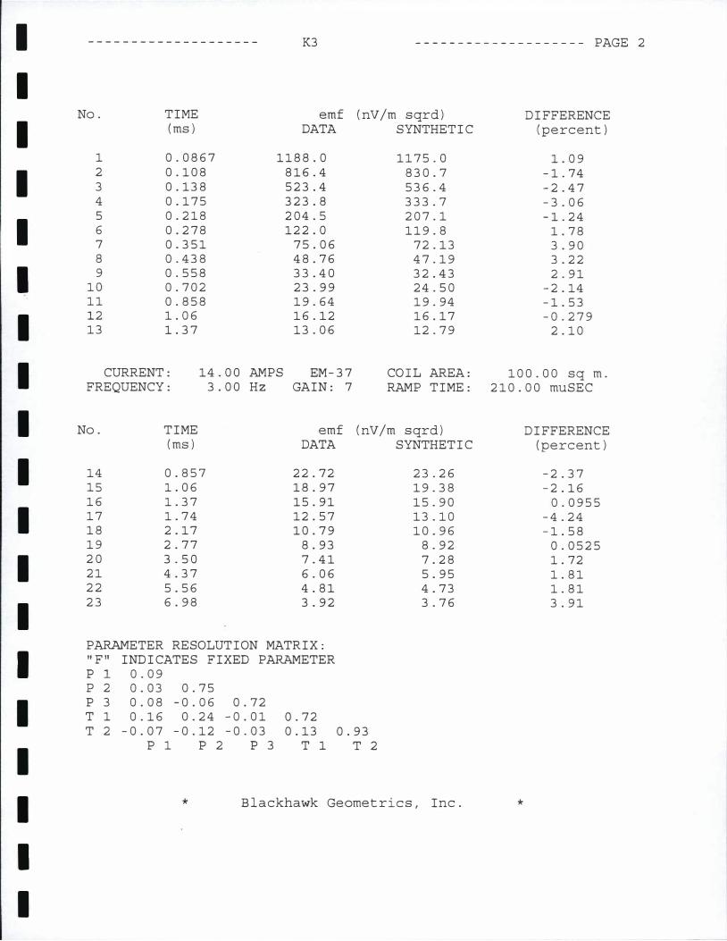
1 0.0867 1188.0 1175.0 1. 09 2 0.108 816.4 830.7 -1.74 3 0.138 523.4 536.4 -2.47 4 0.175 323.8 333.7 -3.06 5 0.218 204.5 207.1 -1.24 6 0.278 122.0 119.8 1.78 7 0.351 75.06 72.13 3.90 8 0.438 48.76 47.19 3.22 9 0.558 33.40 32.43 2.91
10 0.702 23.99 24.50 -2.14 11 0.858 19.64 19.94 -1.53 12 1. 06 16.12 16.17 -0.279 13 1. 37 13.06 12.79 2.10
CURRENT: 14.00 AMPS EM-37 COIL AREA: 100.00 sq m. FREQUENCY: 3.00 Hz GAIN: 7 RAMP TIME: 210.00 muSEC
No. TIME emf (nV/m sqrd) DIFFERENCE (ms) DATA SYNTHETIC (percent)
14 0.857 22.72 23.26 -2.37 15 1. 06 18.97 19.38 -2.16 16 1. 37 15.91 15.90 0.0955 17 1. 74 12.57 13.10 -4.24 18 2.17 10.79 10.96 -1.58 19 2.77 8.93 8.92 0.0525 20 3.50 7.41 7.28 1. 72 21 4.37 6.06 5.95 1. 81 22 5.56 4.81 4.73 1. 81 23 6.98 3.92 3.76 3.91
PARAMETER RESOLUTION MATRIX: "F" INDICATES FIXED PARAMETER p 1 0.09 p 2 0.03 0.75 p 3 0.08 -0.06 0.72 T 1 0.16 0.24 -0.01 0.72 T 2 -0.07 -0.12 -0.03 0.13 0.93
p 1 p 2 p 3 T 1 T 2
* Blackhawk Geometries, Inc. *
-------------------
K4
5
10 '
I
4
'E 10 I � 13-a � -
E .c 0
�
j ' >-
1-1---i
> � 10001 � 1-z w 0: <( I ')> 0... 0...
100 <( ...,
10 1
0.01 0. 1 1 10 TIME (ms)
'
I
I
I -E
1 ..c
.+-)
0.
QJ
0
I
I
___ I 100
0
100 -
200 -
300 -
400 -
500 -
600 -
700 -
BOO -
900 -
1000
I I I
'"'I
10 100 1000 10
-
-
-
-
-
-
-
-
4
RESISTIVITY (ohm-m)
I
I
I
I
I
I
I
I
I
I
I
I
I
I
I
I
I
I
I
K4 -------------------- PAGE 1
DATA SET: K4
CLIENT: KSBE LOCATION: KAUPULEHU,
COUNTY: NORTH KONA PROJECT: KAUPELEHU
LOOP SIZE: 457.000
COIL LOC: 0.000
SOUNDING COORDINATES:
DATE : 0 7 - 3 1 -9 9
HUALALAI RANCH SOUNDING: 4
m by m (X),
E:
457.000 m
ELEVATION: 547.10 m EQUIPMENT: Geonics PROTEM
AZIMUTH: 0.000 m (Y) TIME CONSTANT: NONE
200.0000 N: 4.0000 SLOPE: NONE
Central Loop Configuration Geonics PROTEM System
FITTING ERROR: 6.385 PERCENT
L #
1
2
3
RESISTIVITY (ohm-m)
5372.1
944.5
3.68
THICKNESS (meters)
186.4
459.0
ELEVATION (meters)
547.0
360.6
-98.37
ALL PARAMETERS ARE FREE
PARAMETER BOUNDS FROM EQUIVALENCE ANALYSIS
LAYER MINIMUM BEST MAXIMUM
RHO 1 3184.977 5372.106 11606.826
2 756.932
3 2.451
THICK 1 152.789
2 408.585
DEPTH 1 152.789
2 620.875
CURRENT: 14.00 AMPS FREQUENCY:
No. TIME (ms)
30.00 Hz
944.536 1098.891
3.685 5.542
186.409 244.747
459.065 499.259
186.409 244.747
645.474 671.692
EM-37 COIL AREA: GAIN: 7 RAMP TIME:
emf (nV/m sqrd) DATA SYNTHETIC
"* Blackhawk Geometries, Inc.
CONDUCTANCE
(F1) (Siemens)
I'Ttt5.o Jli.3.o 0.0347
-312. r o . 4 8 6
100.00 sq m. 202.00 muSEC
*
DIFFERENCE (percent)
I
I
I
I
I
I
I
I
I
I
I
I
I
I
·I
I
I
I
I
K4 -------------------- PAGE 2
No. TIME emf (nV/m sqrd) DIFFERENCE (ms) DATA SYNTHETIC (percent)
1 0.0867 1366.5 1366.8 -0.0248 2 0.108 875.9 907.0 -3.55 3 0.138 517.4 543.2 -4.99 4 0.175 302.2 315.6 -4.42 5 0.218 202.4 187.3 7.45 6 0.278 109.7 107.8 1. 78 7 0.351 76.88 68.48 10.93 8 0.438 45.06 49.03 -8.81 9 0.558 37.97 37.14 2.19
10 0.702 25.82 30.04 -16.32 11 0.858 24.13 25.21 -4.49 12 1. 06 22.02 20.97 4.75 13 1. 37 18.15 16.84 7.20
CURRENT: 14.00 AMPS EM-37 COIL AREA: 100.00 sq m. FREQUENCY: 3.00 Hz GAIN: 7 RAMP TIME: 202.00 muSEC
No. TIME emf (nV /m sqrd) DIFFERENCE (ms) DATA SYNTHETIC (percent)
14 0.857 29.39 30.46 -3.65 15 1. 06 26.48 26.07 1. 52 16 1. 37 23.28 21.78 6.43 17 1. 74 16.61 18.31 -10.21 18 2.17 15.93 15.54 2.49 19 2.77 12.32 12.86 -4.38 20 3.50 11.03 10.68 3.20 21 4.37 9.07 8.87 2.21 22 5.56 7.31 7.19 1. 71 23 6.98 6.14 5.83 5.09
PARAMETER RESOLUTION MATRIX: "F" INDICATES FIXED PARAMETER p 1 0.05 p 2 0.09 0.73 p 3 0.06 -0.03 0.64 T 1 0.09 0.32 -0.08 0.53 T 2 -0.03 -0.13 -0.02 0.18 0.92
p 1 p 2 p 3 T 1 T 2
* Blackhawk Geometries, Inc. *
-------------------
5
10
I
L1
'E 10 I � E
.r::::. 0
-
j >-
1-1---<
> � 10001 1-z w a:
I <{ 0... 0...
100 <{
...,
10 l
0.01 0. 1
K5
��
�
1 TIME (ms)
�
I
I
I
l I
I
I
10 100
0
100 -
200 -
300 -
.--. LlOO -
E
..c 500 -
-4-.J
0.
QJ 600 0 -
700 -
BOO -
900 -
1000
1
I I I
-
'I "I 'I
10 100 1000 10
-
-
-
-
-
-
-
-
-
4
RESISTIVITY (ohm-m)
I
I
I
I
I
I
I
I
I
I
I
I
I
I
I
I
I
I
I
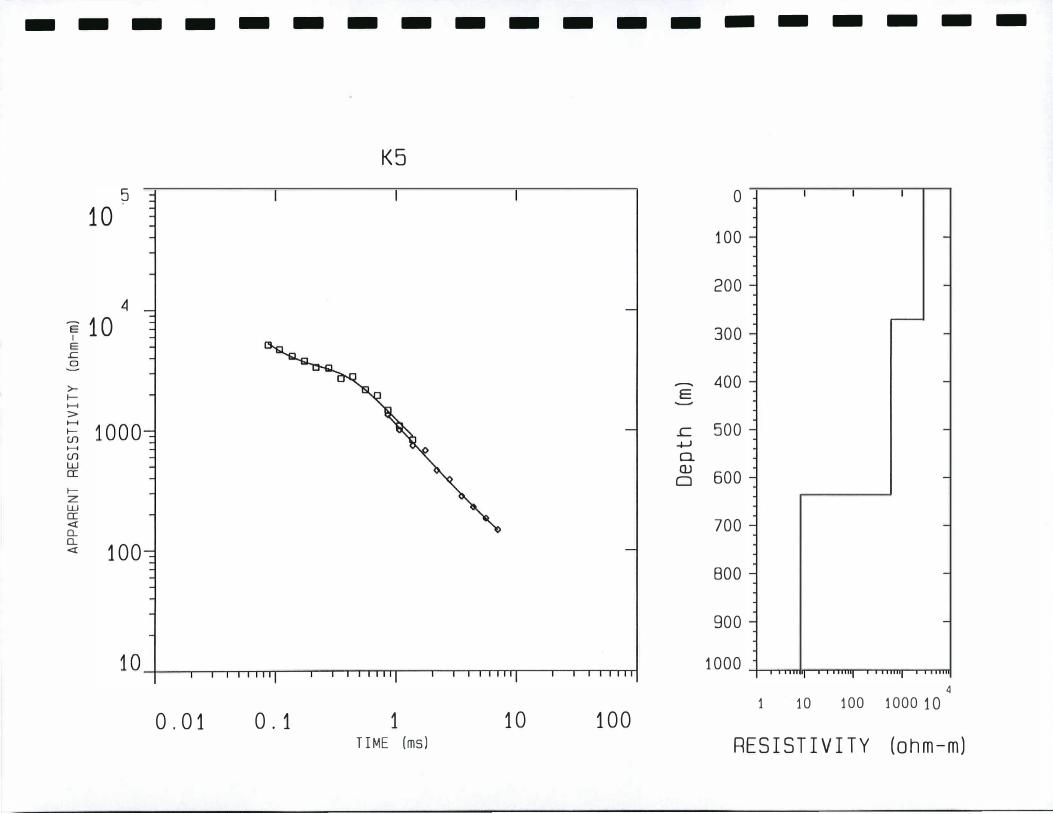
K5 -------------------- PAGE 1
DATA SET: K5
CLIENT: KSBE LOCATION: KAUPULEHU,
COUNTY: NORTH KONA PROJECT: KAUPELEHU
LOOP SIZE: 457.000
COIL LOC: 0.000
SOUNDING COORDINATES:
HUALALAI RANCH DATE: 0 8-01-9 9
SOUNDING: 5
m by m (X),
E:
ELEVATION: 550.20 m EQUIPMENT: Geonics PROTEM
AZIMUTH: 457.000 m 0.000 m (Y)
100.0000 N: TIME CONSTANT: NONE
5.0000 SLOPE: NONE
Central Loop Configuration Geonics PROTEM System
FITTING ERROR: 7.856 PERCENT
L #
1
2
3
RESISTIVITY (ohm-m)
2745.9
588.2
8.30
THICKNESS (meters)
270.4
366.0
ELEVATION (meters)
550.2
279.7
-86.27
ALL PARAMETERS ARE FREE
PARAMETER BOUNDS FROM EQUIVALENCE ANALYSIS
LAYER MINIMUM BEST MAXIMUM
RHO 1 1928.416 2745.996 4530.118
2 432.955 588.212 751.932
3 5.245 8.301 12.693
THICK 1 223.182 270.451 349.246
2 302.437 366.022 422.115
DEPTH 1 223.182 270.451 349.246
2 618.164 636.474 654.556
CURRENT: 14.00 AMPS EM-37 COIL AREA: FREQUENCY:
No. TIME (ms)
·*
30.00 Hz GAIN: 7 RAMP TIME:
emf (nV/m sqrd) DATA SYNTHETIC
Blackhawk Geometries, Inc.
CONDUCTANCE (FT) (Siemens)
IS05.o 911.& 0. 0984
-li3.o 0.622
100.00 sq m. 210.00 muSEC
*
DIFFERENCE (percent)

I
I
I
I
I
I
I
I
I
I
I
I
I
I
I
I
I
I
I
K5 -------------------- PAGE 2
No. TIME emf (nV/m sqrd) DIFFERENCE (ms) DATA SYNTHETIC (percent)
1 0.0867 1799.9 1717.6 4.57
2 0.108 1186.5 1224.0 -3.16
3 0.138 775.6 801.2 -3.30
4 0.175 493.1 508.3 -3.06
5 0.218 342.0 324.5 5.12
6 0.278 190.1 196.3 -3.23
7 0.351 143.5 125.2 12.73
8 0.438 78.22 86.54 -10.63
9 0.558 62.22 62.40 -0.276
10 0.702 41.41 48.14 -16.25
11 0.858 38.45 39.42 -2.50
12 1. 06 35.04 32.00 8.68
13 1. 37 28.06 25.11 10.51
CURRENT: 14.00 AMPS EM -37 COIL AREA: 100.00 sq m. FREQUENCY: 3.00 Hz GAIN: 8 RAMP TIME: 210.00 muSEC
No. TIME emf (nV/m sqrd) DIFFERENCE (ms) DATA SYNTHETIC (percent)
14 0.857 43.83 44.96 -2.56
15 1. 06 39.44 37.35 5.29
16 1. 37 33.13 30.26 8.66
17 1. 74 20.93 24.72 -18.09
18 2.17 21.42 20.40 4.76
19 2.77 15.16 16.38 -8.02
20 3.50 13.69 13.14 4.02
21 4.37 10.73 10.57 1. 48
22 5.56 8.12 8.24 -1.37
23 6.98 6.39 6.43 -0.574
PARAMETER RESOLUTION MATRIX: "F" INDICATES FIXED PARAMETER p 1 0.35
p 2 -0.03 0.64
p 3 0.12 -0.06 0.75
T 1 0.23 0.24 -0.04 0.76
T 2 -0.16 -0.18 0.00 0.17 0.87
p 1 p 2 p 3 T 1 T 2
* Blackhawk Geometries, Inc. *


![REMOTE SENSING AND GIS ANALYSES FOR DETERMINING …lower central region is the Losberg Complex. Many of these findings supported work by geophysical methods [1]. Spectral profiling](https://cdn.vdocuments.site/doc/165x107/60d07c3abf86a23f3c31ba28/remote-sensing-and-gis-analyses-for-determining-lower-central-region-is-the-losberg.jpg)


