
MENU
GC-GEAR COUPLINGS
Version:00.001EN / 25.02.2013 1
The only fully customizable gear coupling in the market
2
TA
BLE
OF C
ON
TE
NT
S
LINE-UP 3
TABLE OF DIMENSIONS Table 1 4
MATERIALS 5
SEALS Figure 1 6
HARDWARE Table 2 7
ATTACHMENTS Figures 2 & 3 8
LUBRICATION Table 3 9
ALIGNMENT PRECISION Tables 4 & 5, diagram 1 10 - 11
INSTALLATION 12
MAINTENANCE 13
WARRANTY TERMS 14
REFERENCES 15
GC-GEAR COUPLINGS
3
LIN
E-U
P
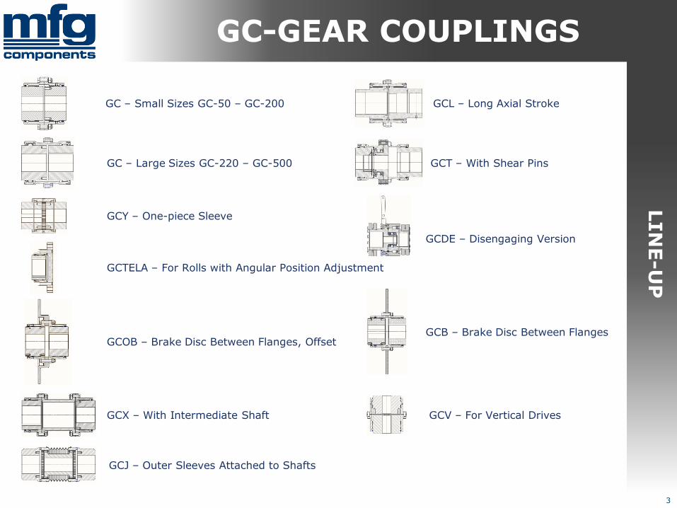
GC – Small Sizes GC-50 – GC-200
GC – Large Sizes GC-220 – GC-500
GCY – One-piece Sleeve
GCTELA – For Rolls with Angular Position Adjustment
GCOB – Brake Disc Between Flanges, Offset
GCX – With Intermediate Shaft
GCB – Brake Disc Between Flanges
GCDE – Disengaging Version
GCJ – Outer Sleeves Attached to Shafts
GCT – With Shear Pins
GCL – Long Axial Stroke
GCV – For Vertical Drives
GC-GEAR COUPLINGS

Torque transfer capacity is given with the base material without heat treatment and with a safety factor of 1.5.
Dimensions Dh and Dn given in table 1 are locked. Other dimensions can be chosen according to the range given.
Puller holes Dph and M can be freely chosen. The recommended dimensions are listed in table 1.
TA
BLE O
F D
IM
EN
SIO
NS
4
Table 1: Dimensions
Dimensions
Type Tnom Tmax D Dh Dn D1/D2 L Ln1/Ln2 S Dph M
GC-60 3 050 6 100 148-250 105 83 20-60 124-254 60-150 6-100 70 M8
GC-70 4 200 8 400 169-250 126 100 20-70 154-254 70-150 6-100 86 M8
GC-90 8 400 16 800 209-300 162 135 30-90 174-254 80-150 6-100 110 M10
GC-110 14 600 29 800 233-300 186 160 40-110 204-404 100-200 6-100 144 M10
GC-130 17 200 34 400 308-400 246 200 50-130 253-613 120-300 12-150 168 M16
GC-160 35 400 70 800 336-500 262 220 60-160 293-613 140-300 12-150 196 M16
GC-180 47 500 95 000 366-500 303 255 80-180 373-813 160-400 12-200 226 M20
GC-200 64 800 129 600 428-600 345 290 80-200 376-820 180-400 16-200 246 M20
GC-220 103 600 207 200 458-600 394 320 80-220 416-820 200-400 16-200 284 M20
GC-240 165 000 330 000 497-700 440 360 100-240 462-820 220-400 22-250 314 M24
GC-260 219 000 438 000 534-800 474 380 100-260 563-820 280-400 22-250 330 M24
GC-300 250 500 501 000 580-800 518 431 160-300 563-820 300-400 22-250 390 M30
GC-365 345 000 690 000 668-800 586 480 180-365 630-830 300-400 30-250 422 M30
GC-400 480 000 960 000 730-800 642 530 200-400 630-830 300-450 30-300 478 M30
GC-450 661 000 1 322 000 830-900 720 621 200-450 630-930 300-450 30-300 560 M30
GC-500 790 000 1 580 000 882-900 742 651 200-500 730-1030 350-500 30-300 600 M30
GC-GEAR COUPLINGS
Standard materials:
– Sleeve and hub: 42CrMo4 QT
– End flanges: S355
– Intermediate shafts and misc. parts: S355
Special materials:
– AiSi304 / AiSI316 (GCRST)
– 34CrNiMo6 (GCHD)
– AlSiMg (GCAL)
GC-Couplings do not have any special surface finishing as standard. Available finishes:
– Painting (hubs are not painted)
– Blueing and parkerizing
– Anodizing
– Zinc plating
Available heat treatments:
– Nitriding
– Induction hardening (teeth only)
– Carburizing
MA
TE
RIA
LS
5
GC-GEAR COUPLINGS
Some finishes and heat treatments are material dependant
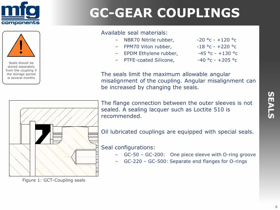
Available seal materials:
– NBR70 Nitrile rubber, -20 °c - +120 °c
– FPM70 Viton rubber, -18 °c - +220 °c
– EPDM Ethylene rubber, -45 °c - +130 °c
– PTFE-coated Silicone, -40 °c - +205 °c
The seals limit the maximum allowable angular misalignment of the coupling. Angular misalignment can be increased by changing the seals.
The flange connection between the outer sleeves is not sealed. A sealing lacquer such as Loctite 510 is recommended.
Oil lubricated couplings are equipped with special seals.
Seal configurations:
– GC-50 – GC-200: One piece sleeve with O-ring groove
– GC-220 – GC-500: Separate end flanges for O-rings
Figure 1: GCT-Coupling seals
6
SE
ALS
Seals should be stored separately
from the coupling if the storage period is several months
GC-GEAR COUPLINGS

7
Only DIN standard hardware is used in GC couplings.
All hardware should be grade 8.8 or higher.
The flange connection between the outer sleeves is achieved with fitted screws and metal lock nuts, which also center the sleeves together.
Standard hardware is either zinc plated or parkerized. Special hardware, such as stainless steel, is available on request.
All screws should be torqued according to table 2.
HA
RD
WA
RE Tightening Torques
Values listed are valid for lightly oiled threads
Thread Grade 8.8 Grade 10.9 Grade 12.9
M8 25 Nm 36 Nm 43 Nm
M10 49 Nm 72 Nm 84 Nm
M12 85 Nm 125 Nm 145 Nm
M16 210 Nm 310 Nm 365 Nm
M20 425 Nm 610 Nm 710 Nm
M24 730 Nm 1050 Nm 1220 Nm
M30 1450 Nm 2100 Nm 2450 Nm
Table 2: Tightening Torques
Hardware of lower grade than the
originals must not be used
GC-GEAR COUPLINGS

The most common attachment is a fitted bore and a keyway.
GC couplings are available with a variety of attachments:
– Bore & keyway or multiple keyways
– MAV locking devices and shrink discs
– Bore with oil release grooves
– Conical bore
– DIN5480 spline
– Form shafts, such as rectangular
– Flange connections
Hub and shaft fit is always chosen according to customer demand. H7/m6 or J7/m6 is recommended for most applications.
The necessary attachment may serve as the sizing base for the entire coupling, large shaft with a low torque, for example.
Figure 2: Fitted bore & Keyway
Figure 3: Stepped bore with
Oil release grooves
AT
TA
CH
ME
NT
S
8
GC-GEAR COUPLINGS
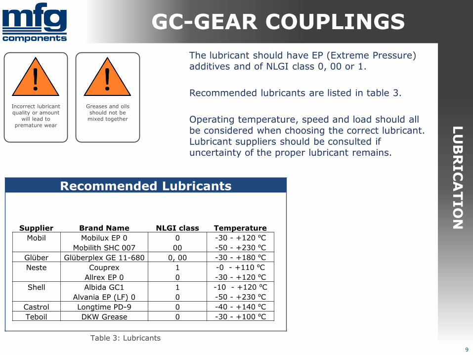
The lubricant should have EP (Extreme Pressure) additives and of NLGI class 0, 00 or 1.
Recommended lubricants are listed in table 3.
Operating temperature, speed and load should all be considered when choosing the correct lubricant. Lubricant suppliers should be consulted if uncertainty of the proper lubricant remains.
LU
BR
IC
AT
IO
N
9
Incorrect lubricant quality or amount
will lead to premature wear
Recommended Lubricants
Supplier Brand Name NLGI class Temperature
Mobil Mobilux EP 0 0 -30 - +120 ⁰C
Mobilith SHC 007 00 -50 - +230 ⁰C
Glüber Glüberplex GE 11-680 0, 00 -30 - +180 ⁰C
Neste Couprex 1 -0 - +110 ⁰C
Allrex EP 0 0 -30 - +120 ⁰C
Shell Albida GC1 1 -10 - +120 ⁰C
Alvania EP (LF) 0 0 -50 - +230 ⁰C
Castrol Longtime PD-9 0 -40 - +140 ⁰C
Teboil DKW Grease 0 -30 - +100 ⁰C
Table 3: Lubricants
Greases and oils should not be
mixed together
GC-GEAR COUPLINGS

10
Max. Deviations
Type α X
GC-60 1,0 ⁰ 0,09
GC-70 1,0 ⁰ 0,09
GC-90 1,0 ⁰ 0,09
GC-110 1,0 ⁰ 0,09
GC-130 1,0 ⁰ 0,21
GC-160 1,0 ⁰ 0,21
GC-180 1,0 ⁰ 0,21
GC-200 1,0 ⁰ 0,28
GC-220 1,0 ⁰ 0,28
GC-240 1,0 ⁰ 0,38
GC-260 1,0 ⁰ 0,38
GC-300 1,0 ⁰ 0,38
GC-365 1,0 ⁰ 0,52
GC-400 1,5 ⁰ 0,52
GC-450 1,5 ⁰ 0,52
GC-500 1,5 ⁰ 0,52
ALIG
NM
EN
T P
RE
CIS
IO
N
Alignment precision requirements for special versions can be found in the assembly drawing of the coupling.
Values listed in table 4 are valid for a coupling in normal use, rotating at max. 1500 1/min. Radial misalignment X is given at the largest allowed angular misalignment and according to the shortest value S listed in table 1.
Maximum tooth backlash for each coupling is listed in table 5.
The relationship between angular misalignment, rotating speed and torque transfer capacity is give in diagram 1. The values are approximate.
Table 5: Backlash Table 4: Deviations
Max. Backlash
Type Backlash
GC-60 0,52
GC-70 0,52
GC-90 0,61
GC-110 0,61
GC-130 0,81
GC-160 0,81
GC-180 1,02
GC-200 1,02
GC-220 1,20
GC-240 1,20
GC-260 1,38
GC-300 1,67
GC-365 1,71
GC-400 1,94
GC-450 1,94
GC-500 1,94
GC-GEAR COUPLINGS

11
0%
10%
20%
30%
40%
50%
60%
70%
80%
90%
100%
0,01 0,10 0,20 0,30 0,40 0,50 0,60 0,70 0,80 0,90 1,00
To
rqu
e tr
an
sfe
r, [
% T
n m
ax]
Angular misalignment, [⁰ / Coupling]
0.05 x n
0.10 x n
0.20 x n
0.30 x n
0.40 x n
0.50 x n
0.60 x n
0.70 x n
0.80 x n
0.90 x n
1.00 x n
ALIG
NM
EN
T P
RE
CIS
IO
N
Diagram 1: Angular misalignment and velocity in relation to torque transfer
GC-GEAR COUPLINGS

12
IN
ST
ALLA
TIO
N
General installation instructions:
- Align the coupled machines according to the values listed in table 3.
- Clean the outside of the coupling.
- Measure the shaft and the coupling bore to check the fit.
- Heat the hub to max. 130 ⁰C if required, and cool
the shaft with liquid nitrogen.
- Slide the end flange and sleeve on to the shaft without the seals before the hub.
- Install the hub on to the shaft and let it cool before installing the seals.
- Seal the keyway on the end of the hub with a proper sealing lacquer or paste.
- Pre-lubricate the teeth and install the sleeve on to the hub.
- Seal the flange connection between the sleeves with a proper sealing lacquer.
- Connect the flanges together with the hardware supplied with the coupling and tighten them according to table 2.
- Lubricate the coupling by opening at least one fill plug and filling the coupling with grease through the other plug.
- Double check screw tightness and install the coupling cover (Cover sold separately).
An improperly torqued screw can come loose and
damage the coupling
Inaccurate alignment will lead to premature wear
Altering coupling parts by welding is strictly forbidden
Angular misalignment
should be at least 0.01⁰ after alignment
A large angular misalignment can cause axial forces as the teeth slide against each other
GC-GEAR COUPLINGS
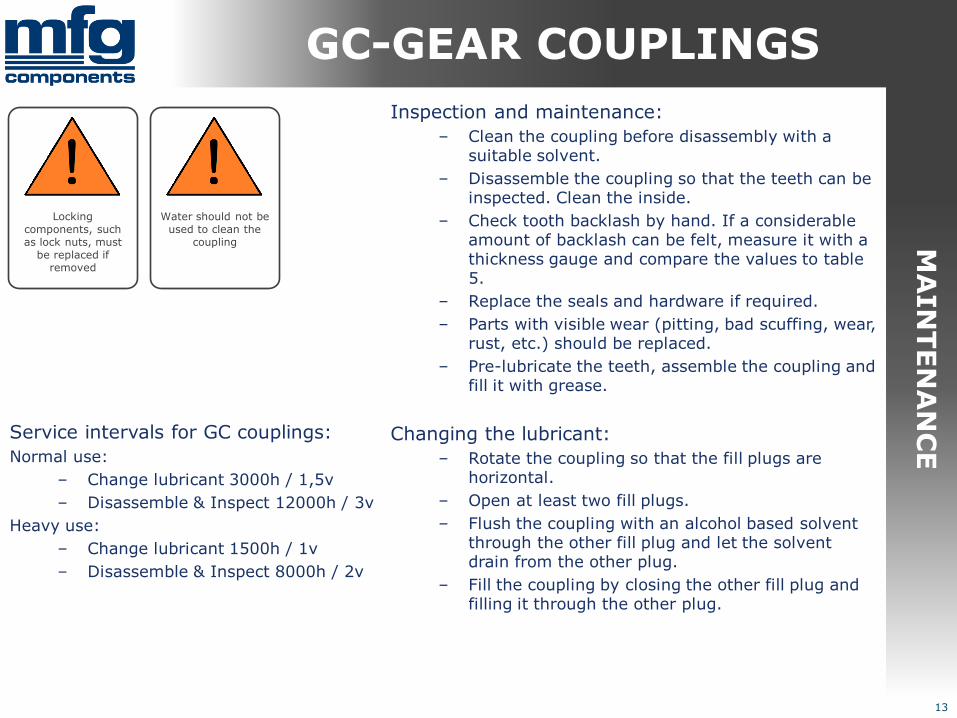
Inspection and maintenance:
– Clean the coupling before disassembly with a suitable solvent.
– Disassemble the coupling so that the teeth can be inspected. Clean the inside.
– Check tooth backlash by hand. If a considerable amount of backlash can be felt, measure it with a thickness gauge and compare the values to table 5.
– Replace the seals and hardware if required.
– Parts with visible wear (pitting, bad scuffing, wear, rust, etc.) should be replaced.
– Pre-lubricate the teeth, assemble the coupling and fill it with grease.
Changing the lubricant:
– Rotate the coupling so that the fill plugs are horizontal.
– Open at least two fill plugs.
– Flush the coupling with an alcohol based solvent through the other fill plug and let the solvent drain from the other plug.
– Fill the coupling by closing the other fill plug and filling it through the other plug.
13
MA
IN
TE
NA
NC
E
Locking components, such as lock nuts, must
be replaced if removed
Water should not be used to clean the
coupling
Service intervals for GC couplings:
Normal use:
– Change lubricant 3000h / 1,5v
– Disassemble & Inspect 12000h / 3v
Heavy use:
– Change lubricant 1500h / 1v
– Disassemble & Inspect 8000h / 2v
GC-GEAR COUPLINGS
Warranty terms for GC couplings:
– The customer has provided MFG with adequate data of the drive.
– Screw tightening torques, grease type and quantity and alignment precision has been documented during installation.
– The coupling has been installed in the drive it was first designated for, and the drive has not been altered after designation.
– Only fasteners and seals supplied with the coupling have been used.
– The coupling has been properly filled with a grease recommended by MFG while taking note of the ambient temperature.
– The coupling has not been damaged during installation by excess heat or by damaging it.
– The coupling has been stored appropriately, away from solvents and other chemicals.
– The customer has not altered the coupling by machining, welding, etc.
14
WA
RR
AN
TY
TE
RM
S
Indirect expenses related to changing the coupling will not
be covered
GC-GEAR COUPLINGS
15
RE
FE
RE
NC
ES
Pulp & Paper Industry:
– Estonian Cell
– Stora Enso
– Metso Paper
Steel Industry:
– Outokumpu Stainless
Process Industry:
– Flowrox
– ABB Drives
– Andritz Service
– Moventas Gears
GC-GEAR COUPLINGS


