ARTICLE IN PRESS
0736-5845/$ - se
doi:10.1016/j.rc
�CorrespondE-mail addr
Robotics and Computer-Integrated Manufacturing 25 (2009) 379–392
www.elsevier.com/locate/rcim
FPGA implementation of higher degree polynomial acceleration profilesfor peak jerk reduction in servomotors
Roque Alfredo Osornio-Riosa,�, Rene de Jesus Romero-Troncosob,Gilberto Herrera-Ruiza, Rodrigo Castaneda-Mirandaa
aFacultad de Ingenierıa, Universidad Autonoma de Queretaro Cerro de las Campanas s/n, 76010 Queretaro, Qro., MexicobElectronics Department, FIMEE, Universidad de Guanajuato, Tampico 912, Col. Bellavista, 36720 Salamanca, Gto., Mexico
Received 14 December 2006; received in revised form 26 September 2007; accepted 29 January 2008
Abstract
Acceleration profile generation for jerk limitation is a major issue in automated industrial applications like computer numerical
control (CNC) machinery and robotics. The automation machinery dynamics should be kept as smooth as possible with suitable
controllers where trajectory precision ensures quality while smoothness decreases machinery stress. During the operation of
commercially available CNC and robotics controllers, small discontinuities on the dynamics are generated due to the controller position
profiler which is generally based on a trapezoidal velocity profile. These discontinuities can produce undesirable high-frequency
harmonics on the position reference which consequentially can excite the natural frequencies of the mechanical structure and
servomotors. Previous works have developed jerk limited trajectories with higher degree polynomial-based profiles, but lack one or both
of computer efficiency for on-line operation and low-cost hardware implementation. The present work shows a low cost,
computationally efficient, on-line hardware implementation of a high-degree polynomial-based profile generator with limited jerk
dynamics for CNC machines and robotics applications to improve the machining process. The novelty of the paper is the development of
a multiplier-free recursive algorithm for computationally efficient polynomial evaluation in profile generation and a low-cost
implementation of the digital structure in field programmable gate array (FPGA). Two experimental setups were prepared in order to test
the polynomial profile generator: the first one with the servomotor at no load and the second one for the servomotor driving a CNC
milling machine axis. From experimental results it is shown that higher degree polynomial profiles, compared to the standard trapezoidal
speed profile improve the system dynamics by reducing peak jerk in more than one order of magnitude while precision is maintained the
same and on-line operation is guaranteed.
r 2008 Elsevier Ltd. All rights reserved.
Keywords: CNC machinery; Robotics; Jerk; Polynomial profile generator; FPGA
1. Introduction
Nowadays, computer numerical control (CNC) ma-chines and robotics are widely spread in automatedindustrial applications, which improve end product quality,reduce production time and increase profits in the shortand long time, despite the high initial investment. In orderto guarantee an optimal relationship between productquality and production cost, the automation machinery
e front matter r 2008 Elsevier Ltd. All rights reserved.
im.2008.01.002
ing author. Tel./fax: +52 427 2741244.
ess: [email protected] (R.A. Osornio-Rios).
dynamics should be kept as smooth as possible withsuitable controllers where trajectory precision ensuresquality while smoothness decreases machinery stress.During the operation of commercially available CNC
and robotics controllers, small discontinuities on thedynamics are generated due to the controller positionprofile generator which is generally based on a trapezoidalvelocity profile. The discontinuities on the trajectorydynamics can produce undesirable high-frequency harmo-nics on the position reference, which consequentially canexcite the natural frequencies of the mechanical structureand servomotors. Such high-frequency harmonics can also
ARTICLE IN PRESSR.A. Osornio-Rios et al. / Robotics and Computer-Integrated Manufacturing 25 (2009) 379–392380
saturate the actuators and therefore, decrease the positiontrajectory precision that affects the effective contouringprocess. Linear and circular interpolation techniques havebeen proposed to minimize the discontinuities; however,these techniques have limited efficiency when the geometryof the machining process is complex, which decreaseproductivity in CNC machines and do not provide therequired smooth dynamics in robotics.
The parameter that measures the discontinuities anddynamics smoothness is known as jerk and it is defined asthe acceleration change rate. Sudden control changes inacceleration result in higher jerk levels which can stimulatethe mechanical systems into resonance; therefore, it isnecessary to provide position profiles sufficiently smooth inorder to reduce jerk levels, minimizing discontinuities andavoiding system resonance.
Hardware and software digital signal processing (DSP)techniques have been proposed to develop algorithms forjerk reduction in industrial controllers. By minimizing jerk,two immediate benefits are granted: machinery stress andvibration reduction on the dynamics and smoother move-ment which allows speed increasing while error is reduced.In consequence, overall performance can be improvedwhen jerk is limited.
According to Erkorkmaz and Altintas [1], trapezoidalspeed profiles generate high-frequency harmonics in theacceleration dynamics which yields poor jerk behavior.They also showed that higher degree polynomial-basedprofiles give a smoother dynamics, making the resultingtrajectory easier to track by the limited bandwidth of theservo controller.
Higher degree polynomial profiles are difficult togenerate due to the computational load demands bothhardware resources and processing time, which seriouslycompromise on-line implementation for controllers inpractice. Direct polynomial evaluation algorithms demandhigh computational efforts to be made at the processorsystem, highly increased by the polynomial degree.
The present work shows a low cost, computationallyefficient, on-line hardware implementation of a high-degreepolynomial-based profile generator with limited jerkdynamics for CNC machines and robotics applications toimprove the machining process. The novelty of the paper isthe development of a multiplier-free recursive algorithm forcomputationally efficient polynomial evaluation in profilesgeneration, suited for any processing unit (DSP, micro-processor, etc.) and its special purpose digital structureoptimized for field programmable gate array (FPGA)which due to its reconfigurability allows a system on-a-chip(SOC) approach while its architecture freedom, from thedesigner point of view, improves the servo loop updatetime for conventional and high-speed machining with ahigh-resolution parallel processing structure. Considerablejerk reduction is obtained by the design of higher degreepolynomial profiles with overall dynamics smoothness (i.e.limited jerk polynomial profile that gives smooth accelera-tion, velocity and position profiles).
2. Background
Several research lines have been followed to improve thejerk limitation dynamics on CNC and robotics controllers.The reported algorithms deal with higher degree poly-nomial profile generators in software and hardware;however, all of them use the direct polynomial evaluationwhich is not computationally efficient because this techni-que requires floating-point operations to achieve the suitedprecision, besides being computational intensive, compro-mising on-line implementation. Personal computer (PC)-based software implementation of the direct polynomialevaluation, though achieves the required precision, lacksthe on-line restriction due to the computational intensivenature of the algorithm. On the other hand, for a generalpurpose microprocessor or DSP system, high resources arerequired for the hardware section in order to achieve on-line operation while keeping the error bounded, generallyrequiring expensive floating-point units or complicatedmultiple precision operations, making the algorithmunsuited for polynomials of 5 or higher degrees.Erkorkmaz and Altintas [1] developed an algorithm for
limited jerk trajectory generation which highlights thepolynomial approach advantages over the traditionaltrapezoidal profile approach. This work deals with a fifthdegree multiple polynomial generation and its implementa-tion into a TMS C32 commercially available DSP board,recognizing the computing resources demand for thesolution. Yih [2] presents the design of a third-order linearfilter for jerk limitation on CNC machines in order toimprove the servomotor position profile. This approachfilters the original trapezoidal profile for smoothing therelated discontinuities, but lacks the required precision dueto the filter side effects. The implementation is done into anADSP21060 commercially available DSP where the com-putation load is relaxed with the aid of three circularbuffers. Gasparetto and Zanotto [3] proposed a newmethodology for smooth trajectory planning in roboticsbased on a quadratic jerk profile for a fifth degreepolynomial spline. This work highlights the relevance onjerk limitation for robotics structure damage reductionalong with the avoidance of resonance frequencies thatincrease the error; no implementation is presented and onlysimulation results are shown. Another development forrobotics is presented by Yang et al. [4], where the positionprofile selection is stated as a priority in an adaptiveposition controller. The main goal for the trajectoryplanning is to smooth the displacement. The developedalgorithm is presented as software simulations underSimulink and Matlab. Heo et al. [5] presented a develop-ment on profile generation, related to the machiningprocess time for molds and dies. The errors in themachining process are reported as a function of theacceleration and deceleration profiles, implemented insoftware. Cheng et al. [6] proposed a code generatorfor a NURBS interpolator and states that a positionreference profile generator as a high-speed hardware unit is
ARTICLE IN PRESSR.A. Osornio-Rios et al. / Robotics and Computer-Integrated Manufacturing 25 (2009) 379–392 381
mandatory in order to achieve on-line CNC control. Thisdevelopment is implemented with a PC and a TMS320C32DSP working together. Earlier polynomial-based NURBStrajectory planning algorithms were developed by Zhangand Greenway [7], and were programmed under C++ in aPC where it became obvious that on-line implementationof robotics trajectories with this approach were compro-mised due to the computational load, increasing thesampling period. Marchenko et al. [8] worked on aNURBS interpolator for CNC machines with adaptivecontrol for a constant feed rate. The algorithm wasprogrammed under Visual C++ and executed in a400MHz Pentium II-based PC with a Delta Tau PMACcommercial controller board. In order to implementthe algorithm, the sampling period 4� 10�3 s, which isfour times higher than the typical 1� 10�3 s servo loopcontrol time. Cervera and Trevelyan [9] developed anoptimization evolving structure for NURBS trajectorygeneration where its implementation in a PC takes 14.62 s,in order to perform the interpolation. Macfarlane andCroft [10] presented an on-line method for obtainingsmooth, jerk-bounded trajectories; their method describedherein uses a concatenation of fifth-order polynomials toprovide a smooth trajectory between two-way points. Thealgorithm was implemented in Matlab. All the cited worksclaim for an improvement in computation load whichdisables on-line application or increases the resourcerequirements.
On the other hand, FPGA implementation of specialpurpose hardware signal processing units for CNCapplications has became the state-of-the-art approachwhere low-cost, SOC and high computation power isrequired. Jeon and Kim [11] developed an FPGA-basedtrapezoidal acceleration and deceleration profile generatorfor industrial robotics applications, but the digital structureis not optimal, and although polynomial profile generationis mentioned in the work, no actual implementation ispresented because the authors estimated that the hardwareresources will increase exponentially with the polynomialdegree, based on a direct polynomial evaluation algorithm.Jimeno et al. [12] worked on an FPGA-based tool pathcomputation applied to shoe last machining on CNClathes, this work presents the implementation of the surfacevirtual digitalization for the specific tool geometry and itsdisplacement. The research focuses on the computationefficiency as well as precision and speed achieved by theFPGA application. Chen and Lin [13] developed anFPGA-based ultrasonic servomotor drive, highlightingthe speed performance efficiency, compared with othertechnologies, along with the device flexibility and thecapacity for non-linear real time system implementation.Girau and Boumaza [14] presented an embedded architec-ture to solve the navigation problem in robotic based onFPGA that computes trajectories along a harmonicpotential. Their architecture proposed allows very largeprecisions and computer resolution. Software implementa-tion of the harmonic function computation on a micro-
processor-based computer, Pentium 4, 2GHz required100� 10�6 s per iteration, while in FPGA structurerequired around 193� 10�9 s. These works are a fewexamples of FPGA applications for industrial CNC androbotics and its low-cost, flexibility and speed advantages.Previously cited works use several methodologies for
polynomial reference profile generation, and in some casesthe hardware implementation is presented as well, wherethe main identified problems are: computational load,execution time constraints and hardware requirements; nolow-cost computationally efficient solution is presented.This paper deals with two main goals: the development of amultiplier-free computationally efficient polynomial eva-luation algorithm and its digital structure to be implemen-ted into an FPGA, having in mind that low-cost on-lineoperation is mandatory for profile generation. Jerklimitation can be achieved with higher degree polynomials,while precision on position control is guaranteed, as shownby experimentation.
3. Hardware polynomial-based profile generator
The proposed profile generator is based in a multiplier-free polynomial evaluation algorithm which reconstructsthe polynomial by a parameterization process usingsuccessive discrete time integration. The algorithm can beeasily implemented into an FPGA, requiring simplestructures as adders and registers plus logic. Hardwarerequirements increase linearly with the polynomial degreewhile computation time is not sacrificed. Multiple precisionaccumulation is performed by the digital structure in orderto guarantee the desired reference accuracy. In order to testthe profile generator performance and to show theversatility of the FPGA implementation, several comple-mentary digital structures were developed and integrated inthe design. Hardware description language VHDL (veryhigh-speed integrated circuit hardware description lan-guage) is used as the design platform for the FPGAimplementation.
3.1. Parameterization algorithm for polynomial evaluation
The parameterization of a polynomial is the mathema-tical process that extracts the minimum number of finitequantities that are necessary to reconstruct the givenpolynomial from an algorithm. Let WK(k) be an n-degreediscrete polynomial on k, where the most widely knownparameterization algorithms for these polynomials arecoefficient parameterization (1) and zeroes parameteriza-tion (2), where ai are the characteristic coefficients and zi
are the polynomial zeroes, being C the group constant.Both parameterization algorithms are equivalent andrequire (n+1) parameters to characterize the polynomial:
W ðkÞ ¼ a0 þ a1k þ a2k2þ � � � þ ankn, (1)
W ðkÞ ¼ Cðk � z1Þðk � z2Þ . . . ðk � znÞ. (2)
ARTICLE IN PRESSR.A. Osornio-Rios et al. / Robotics and Computer-Integrated Manufacturing 25 (2009) 379–392382
From the computational point of view, both algorithmsrequire multiplications and additions to evaluate for aspecific value of k. Other parameterization algorithms areavailable for the polynomial evaluation that are bettersuited from the computational point of view such asrecursive algorithms based on equally spaced evaluationpoints, which is the case for a discrete-time polynomial-based profile, where the operations to be computed areadditions only.
The recursive approach theory can be checked inRef. [15] and it is outlined next. Let WK(k) be an n-degreediscrete polynomial on k for K samples to be evaluated.The recursive discrete differences Dj on WK(k) are definedby Eq. (3) where it must be noted that the (n+1)th andhigher degree differences are zero.
DW K ðkÞ ¼W ðkÞ �W ðk � 1Þ;
D2W K ðkÞ ¼ DW ðkÞ � DW ðk � 1Þ;
� � �
DnW K ðkÞ ¼ Dn�1W K ðkÞ � Dn�1W K ðk � 1Þ;
Dnþ1W K ðkÞ ¼ 0:
(3)
From Eq. (3) it can be deduced the recursive algorithmfor the reconstruction of the original polynomial WK(k) asstated in Eq. (4).
DnW K ðkÞ ¼ DnW K ðk � 1Þ;
Dn�1W K ðkÞ ¼ DnW K ðkÞ þ Dn�1W K ðk � 1Þ;
� � �
DW K ðkÞ ¼ D2W K ðkÞ þ DW K ðk � 1Þ;
W K ðkÞ ¼ DW K ðkÞ þW K ðk � 1Þ:
(4)
In order to recursively reconstruct WK(k) from Eq. (4) atthe start point k ¼ 0, the value of the n differences must beknown at k ¼ �1 as parameters which are the only dataneeded to parameterize the multiplier free algorithm, beingthese parameters the differences: DnWK(�1), D
n�1WK(�1),y, D1WK(�1) and WK(�1).
From the cited literature [1,3–13], it can be seen that theapproach followed by these works is the direct computa-tion of the polynomial. Direct polynomial evaluation, in itsbest implementation, requires n+1 multiplications andadditions in at least 64-bit floating-point numericalprecision for each computed value; therefore, the computa-tional load is compromised for on-line applications. On theother hand, recursive computation is based on discretedifferentiations and integrations which imply a multiplierfree approach. Nevertheless, there is a drawback inrecursive algorithms, which is that the error is cumulative
+Z-1ΔJW (k)
+++ Z-1
Fig. 1. Integrator chain block diagram
and increases as the number of samples taken for a givenprofile, K, increases, requiring higher resolution at theadditions in order to keep the error bounded. Theadvantage of the direct computation is that the error isabsolute at each sample, but requires multiplications infloating-point numerical representation; on the other hand,recursive computation is multiplier free and requires fixed-point addition operations only, which are simple and fastto execute, but in order to keep the error bounded, theresolution must be extended up to 96-bit or up fixed-pointnumerical representation. From the implementation pointof view in digital systems, it is better to perform very high-resolution fixed-point additions with error boundingtechniques, than to implement high-resolution floating-point multiplications and additions. The extra cost of veryhigh-resolution fixed-point additions of the recursivealgorithms is compensated in execution time performanceand resource savings, compared with the time penalty andresource requirements for a high-resolution floating-pointunit, as shown by Osornio et al. [16].
3.2. Polynomial-based profile generator digital structure
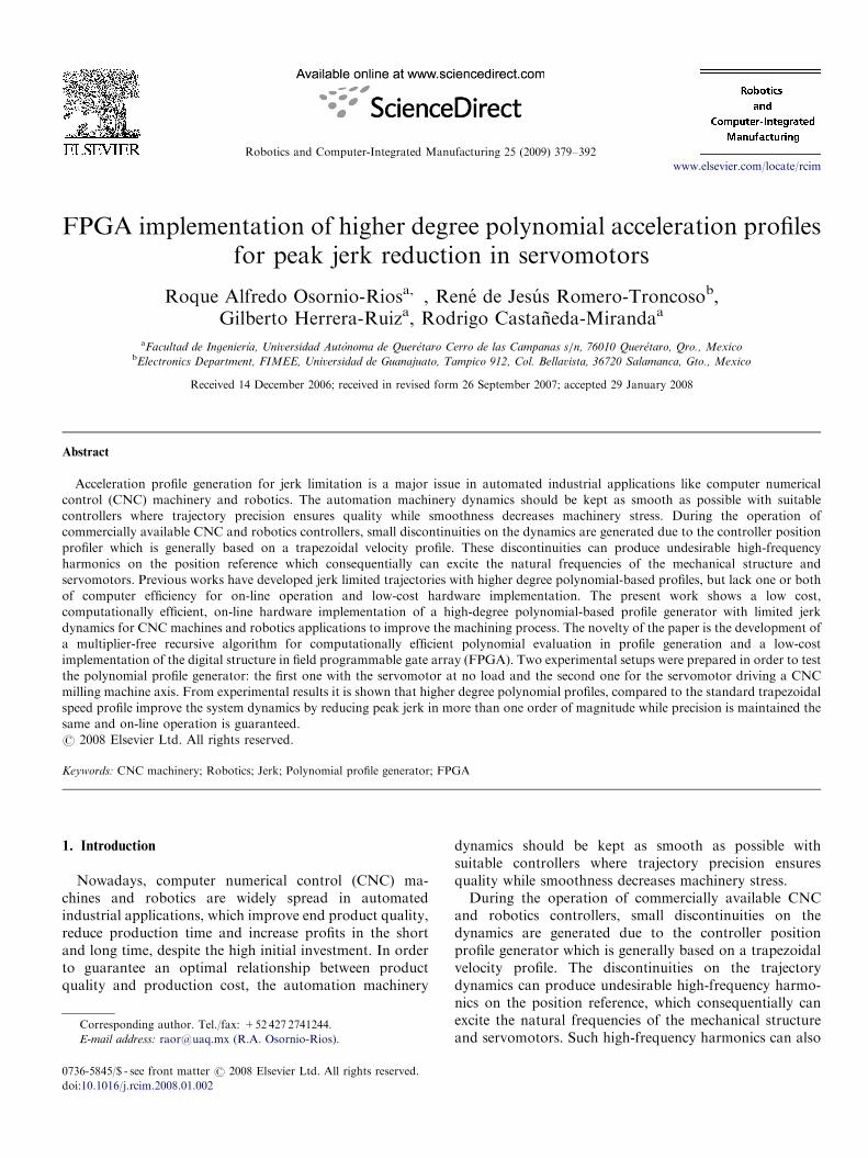
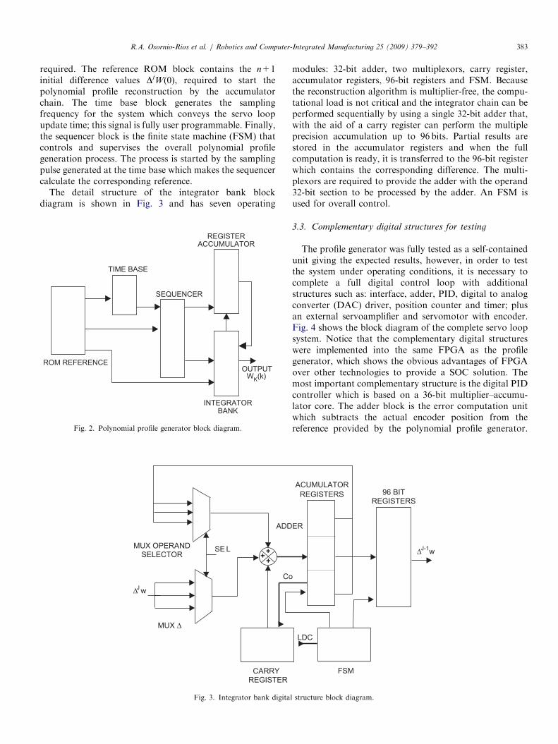
The digital structure for the polynomial evaluationalgorithm stated in Eq. (4) can be efficiently implementedas a consecutive discrete integrator chain as shown in Fig.1. For an n-degree polynomial, the parameterizationrequires n+1 integrators to reconstruct the desiredpolynomial profile reference. The advantage of the algo-rithm is that no multipliers are required and the integratorbank uses adders and registers optimally implemented indigital systems. Besides, as the algorithm is based inadditions, the on-line implementation requirements toachieve very fast servo loop update time is of no concern.The overall delay of the structure and the hardwareresources requirements for Fig. 1 follow a proportionalrelationship with the polynomial degree.The digital structure for the full implementation of the
block diagram in Fig. 1 can be seen in Fig. 2. The system isbased on five blocks: integrator bank, accumulatorregisters, reference read only memory (ROM), time baseand control sequencer. The integrator bank is the core ofthe polynomial profile generator and it is based on a 96-bitmultiple precision accumulator adder. Although thereference position has a 32-bit resolution which is typicalfor optical encoder-based servo loops, 64 additional bitswere used in order to keep the cumulative error bounded.The accumulator registers were used to store the jthdifferences for each integrator; n+1 96-bit registers were
. . .Wk
++Z-1
N+1
for polynomial profile generation.
ARTICLE IN PRESSR.A. Osornio-Rios et al. / Robotics and Computer-Integrated Manufacturing 25 (2009) 379–392 383
required. The reference ROM block contains the n+1initial difference values DjW(0), required to start thepolynomial profile reconstruction by the accumulatorchain. The time base block generates the samplingfrequency for the system which conveys the servo loopupdate time; this signal is fully user programmable. Finally,the sequencer block is the finite state machine (FSM) thatcontrols and supervises the overall polynomial profilegeneration process. The process is started by the samplingpulse generated at the time base which makes the sequencercalculate the corresponding reference.
The detail structure of the integrator bank blockdiagram is shown in Fig. 3 and has seven operating
ROM REFERENCE
TIME BASE
SEQUENCER
REGISTERACCUMULATOR
INTEGRATORBANK
OUTPUTWK(k)
Fig. 2. Polynomial profile generator block diagram.
+++
CARRYREGISTER
MUX Δ
MUX OPERANDSELECTOR
ADD
SE L
CoJΔ w
Fig. 3. Integrator bank digita
modules: 32-bit adder, two multiplexors, carry register,accumulator registers, 96-bit registers and FSM. Becausethe reconstruction algorithm is multiplier-free, the compu-tational load is not critical and the integrator chain can beperformed sequentially by using a single 32-bit adder that,with the aid of a carry register can perform the multipleprecision accumulation up to 96 bits. Partial results arestored in the accumulator registers and when the fullcomputation is ready, it is transferred to the 96-bit registerwhich contains the corresponding difference. The multi-plexors are required to provide the adder with the operand32-bit section to be processed by the adder. An FSM isused for overall control.
3.3. Complementary digital structures for testing
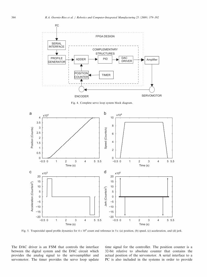
The profile generator was fully tested as a self-containedunit giving the expected results, however, in order to testthe system under operating conditions, it is necessary tocomplete a full digital control loop with additionalstructures such as: interface, adder, PID, digital to analogconverter (DAC) driver, position counter and timer; plusan external servoamplifier and servomotor with encoder.Fig. 4 shows the block diagram of the complete servo loopsystem. Notice that the complementary digital structureswere implemented into the same FPGA as the profilegenerator, which shows the obvious advantages of FPGAover other technologies to provide a SOC solution. Themost important complementary structure is the digital PIDcontroller which is based on a 36-bit multiplier–accumu-lator core. The adder block is the error computation unitwhich subtracts the actual encoder position from thereference provided by the polynomial profile generator.
FSM
ER
ACUMULATORREGISTERS 96 BIT
REGISTERS
J-1
LDC
Δ w
l structure block diagram.
ARTICLE IN PRESS
AmplifierPID DACDRIVERADDER
POSITIONCOUNTER
TIMER
PROFILEGENERATOR
ENCODER
COMPLEMENTARYSTRUCTURES
FPGA DESIGN
SERIALINTERFACE
PC
SERVOMOTOR
Fig. 4. Complete servo loop system block diagram.
0 1 2 3 4 50
1
2
3
4
Pos
ition
(Cou
nts)
0 1 2 3 4 50
2
4
6
8
10
Spe
ed (C
ount
s/s)
−20
−15
−10
−5
0
5
10
15
20
Acc
eler
atio
n (C
ount
s/s2 )
−20
−15
−10
−5
0
5
10
15
20
Jerk
(Cou
nts/
s3 )
x104
x103 x106
x104
Time (s) Time (s)−0.5−0.5
3.5
2.5
1.5
0.5
5.5 5.5
0 1 2 3 4 5 0 1 2 3 4 5Time (s) Time (s)
−0.5−0.5 5.5 5.5
Fig. 5. Trapezoidal speed profile dynamics for 4� 104 count end reference in 5 s: (a) position, (b) speed, (c) acceleration, and (d) jerk.
R.A. Osornio-Rios et al. / Robotics and Computer-Integrated Manufacturing 25 (2009) 379–392384
The DAC driver is an FSM that controls the interfacebetween the digital system and the DAC circuit whichprovides the analog signal to the servoamplifier andservomotor. The timer provides the servo loop update
time signal for the controller. The position counter is a32-bit relative to absolute counter that contains theactual position of the servomotor. A serial interface to aPC is also included in the systems in order to provide
ARTICLE IN PRESSR.A. Osornio-Rios et al. / Robotics and Computer-Integrated Manufacturing 25 (2009) 379–392 385
communication for configuration parameters for the unitsand to monitor the actual position, which is compared withthe profile generator reference.
4. Polynomial profile cases of study
Six cases of study were developed in order to verify theprofile generator efficiency under real system conditions.The first five experiments are polynomial profiles that wereimplemented in the FPGA with no load applied to theservomotor. The polynomial profiles for these experimentsare: trapezoidal speed, biquadratic acceleration, cubicacceleration, quintic acceleration and piecewise cubicsequence in jerk; all of them for three different end referenceof: 1� 104 counts in 1 s, 2� 104 counts in 2 s and 4� 104
counts in 5 s. For the case of study number 6, four profileswere implemented: trapezoidal speed, biquadratic accelera-tion, cubic acceleration and quintic acceleration for an endreference of 4� 104 counts in 5 s with the servomotor actingover a high-speed CNC milling machine feed axis.
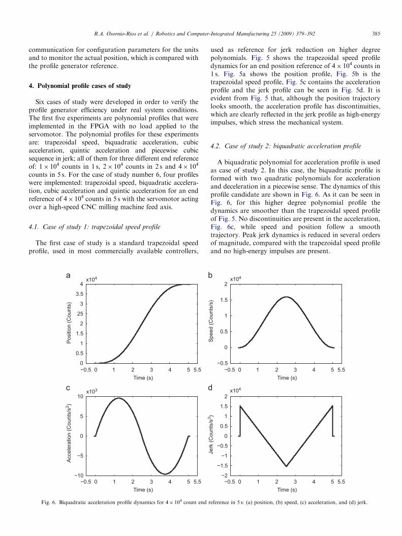
4.1. Case of study 1: trapezoidal speed profile
The first case of study is a standard trapezoidal speedprofile, used in most commercially available controllers,
0 1 2 3 4 50
0.5
1
1.5
2
25
3
3.5
4
Pos
ition
(Cou
nts)
−10
−5
0
5
10
Acc
eler
atio
n (C
ount
s/s2 )
x104
x103
Time (s)−0.5 5.5
0 1 2 3 4 5Time (s)
−0.5 5.5
Fig. 6. Biquadratic acceleration profile dynamics for 4� 104 count end r
used as reference for jerk reduction on higher degreepolynomials. Fig. 5 shows the trapezoidal speed profiledynamics for an end position reference of 4� 104 counts in1 s. Fig. 5a shows the position profile, Fig. 5b is thetrapezoidal speed profile, Fig. 5c contains the accelerationprofile and the jerk profile can be seen in Fig. 5d. It isevident from Fig. 5 that, although the position trajectorylooks smooth, the acceleration profile has discontinuities,which are clearly reflected in the jerk profile as high-energyimpulses, which stress the mechanical system.
4.2. Case of study 2: biquadratic acceleration profile
A biquadratic polynomial for acceleration profile is usedas case of study 2. In this case, the biquadratic profile isformed with two quadratic polynomials for accelerationand deceleration in a piecewise sense. The dynamics of thisprofile candidate are shown in Fig. 6. As it can be seen inFig. 6, for this higher degree polynomial profile thedynamics are smoother than the trapezoidal speed profileof Fig. 5. No discontinuities are present in the acceleration,Fig. 6c, while speed and position follow a smoothtrajectory. Peak jerk dynamics is reduced in several ordersof magnitude, compared with the trapezoidal speed profileand no high-energy impulses are present.
0
1
1.5
2
Spe
ed (C
ount
s/s)
−2
−1
0
1
2
Jerk
(Cou
nts/
s3 )
x104
x104
0.5
−0.5
1.5
0.5
−0.5
−1.5
0 1 2 3 4 5Time (s)
−0.5 5.5
0 1 2 3 4 5Time (s)
−0.5 5.5
eference in 5 s: (a) position, (b) speed, (c) acceleration, and (d) jerk.
ARTICLE IN PRESS
−0.5 0 1 2 3 4 50
0.5
1
1.5
2
2.5
3
3.5
4P
ositi
on (C
ount
s)
−0.5
0
1
1.5
Spe
ed (C
ount
s/s)
−10
−5
0
5
10
Acc
eler
atio
n (C
ount
s/s2 )
−1
−0.5
0
0.5
1
1.5
2
Jerk
(Cou
nts/
s3 )
x104 x104
x103 x104
0.5
Time (s)5.5 −0.5 0 1 2 3 4 5
Time (s)5.5
−0.5 0 1 2 3 4 5Time (s)
5.5 −0.5 0 1 2 3 4 5Time (s)
5.5
Fig. 7. Cubic acceleration profile dynamics for 4� 104 count end reference in 5 s: (a) position, (b) speed, (c) acceleration, and (d) jerk.
R.A. Osornio-Rios et al. / Robotics and Computer-Integrated Manufacturing 25 (2009) 379–392386
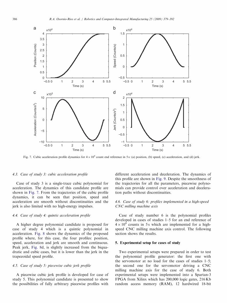
4.3. Case of study 3: cubic acceleration profile
Case of study 3 is a single-trace cubic polynomial foracceleration. The dynamics of this candidate profile areshown in Fig. 7. From the trajectories of the cubic profiledynamics, it can be seen that position, speed andacceleration are smooth without discontinuities and thejerk is also limited with no high-energy impulses.
4.4. Case of study 4: quintic acceleration profile
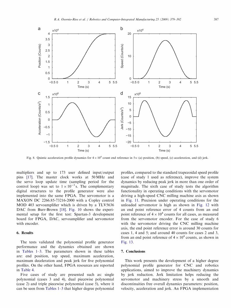
A higher degree polynomial candidate is proposed forcase of study 4 which is a quintic polynomial inacceleration. Fig. 8 shows the dynamics of the proposedprofile where, for this case, the four profiles: position,speed, acceleration and jerk are smooth and continuous.Peak jerk, Fig. 8d, is slightly increased from the biqua-dratic and cubic cases, but it is lower than the jerk in thetrapezoidal speed profile.
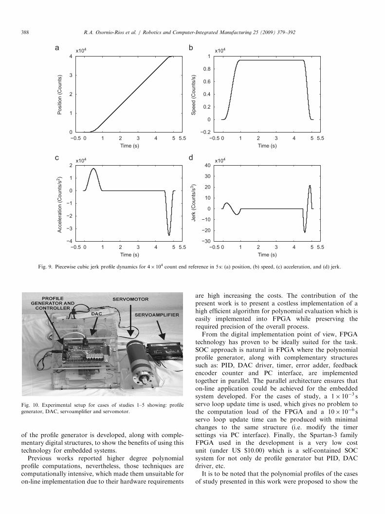
4.5. Case of study 5: piecewise cubic jerk profile
A piecewise cubic jerk profile is developed for case ofstudy 5. This polynomial candidate is presented to showthe possibilities of fully arbitrary piecewise profiles with
different acceleration and deceleration. The dynamics ofthis profile are shown in Fig. 9. Despite the smoothness ofthe trajectories for all the parameters, piecewise polyno-mials can provide control over acceleration and decelera-tion paths without discontinuities.
4.6. Case of study 6: profiles implemented in a high-speed
CNC milling machine axis
Case of study number 6 is the polynomial profilesdeveloped in cases of studies 1–5 for an end reference of4� 104 counts in 5 s which are implemented for a high-speed CNC milling machine axis control. The followingsection shows the results.
5. Experimental setup for cases of study
Two experimental setups were prepared in order to testthe polynomial profile generator: the first one withthe servomotor at no load for the cases of studies 1–5;the second one for the servomotor driving a CNCmilling machine axis for the case of study 6. Bothexperimental setups were implemented into a Spartan-3FPGA from Xilinx which has 200,000 logic gates, 216Kbrandom access memory (RAM), 12 hardwired 18-bit
ARTICLE IN PRESS
−0.5 0 1 2 3 4 50
1
2
3
4
Pos
ition
(Cou
nts)
0
10
20
Spe
ed (C
ount
s/s)
−1
0
0.5
1
1.5
−20
−15
−10
−5
0
5
10
15
Jerk
(Cou
nts/
s3 )
Acc
eler
atio
n (C
ount
s/s2 )
x106
x104
Time (s)
x106
3.5
2.5
1.5
0.5
−0.5
−1.5
x104
5.5 −0.5 0 1 2 3 4 5Time (s)
5.5
−0.5 0 1 2 3 4 5Time (s)
5.5 −0.5 0 1 2 3 4 5Time (s)
5.5
Fig. 8. Quintic acceleration profile dynamics for 4� 104 count end reference in 5 s: (a) position, (b) speed, (c) acceleration, and (d) jerk.
R.A. Osornio-Rios et al. / Robotics and Computer-Integrated Manufacturing 25 (2009) 379–392 387
multipliers and up to 173 user defined input/outputpins [17]. The master clock works at 50MHz andthe servo loop update time (sampling period for thecontrol loop) was set to 1� 10�3 s. The complementarydigital structures to the profile generator were alsoimplemented into the same FPGA. The servomotor is aMAXON DC 2266.85-73216-2000 with a Copley controlMOD 403 servoamplifier which is driven by a TLV5636DAC from Burr-Brown [18]. Fig. 10 shows the experi-mental setup for the first test: Spartan-3 developmentboard for FPGA, DAC, servoamplifier and servomotorwith encoder.
6. Results
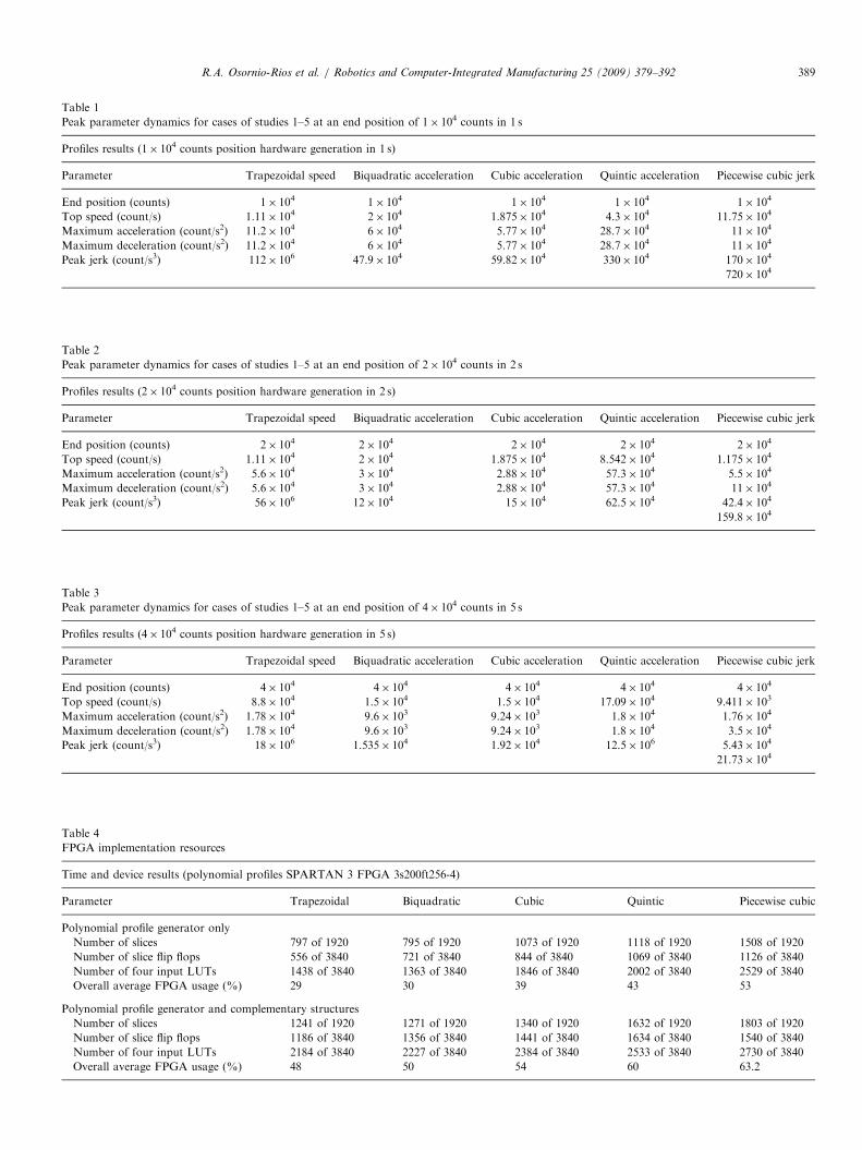
The tests validated the polynomial profile generatorperformance and the dynamics obtained are shownin Tables 1–3. The parameters shown in these tablesare: end position, top speed, maximum acceleration,maximum deceleration and peak jerk for five polynomialprofiles. On the other hand, FPGA resources are reportedin Table 4.
Five cases of study are presented such as: singlepolynomial (cases 3 and 4), dual piecewise polynomial(case 2) and triple piecewise polynomial (case 5), where itcan be seen from Tables 1–3 that higher degree polynomial
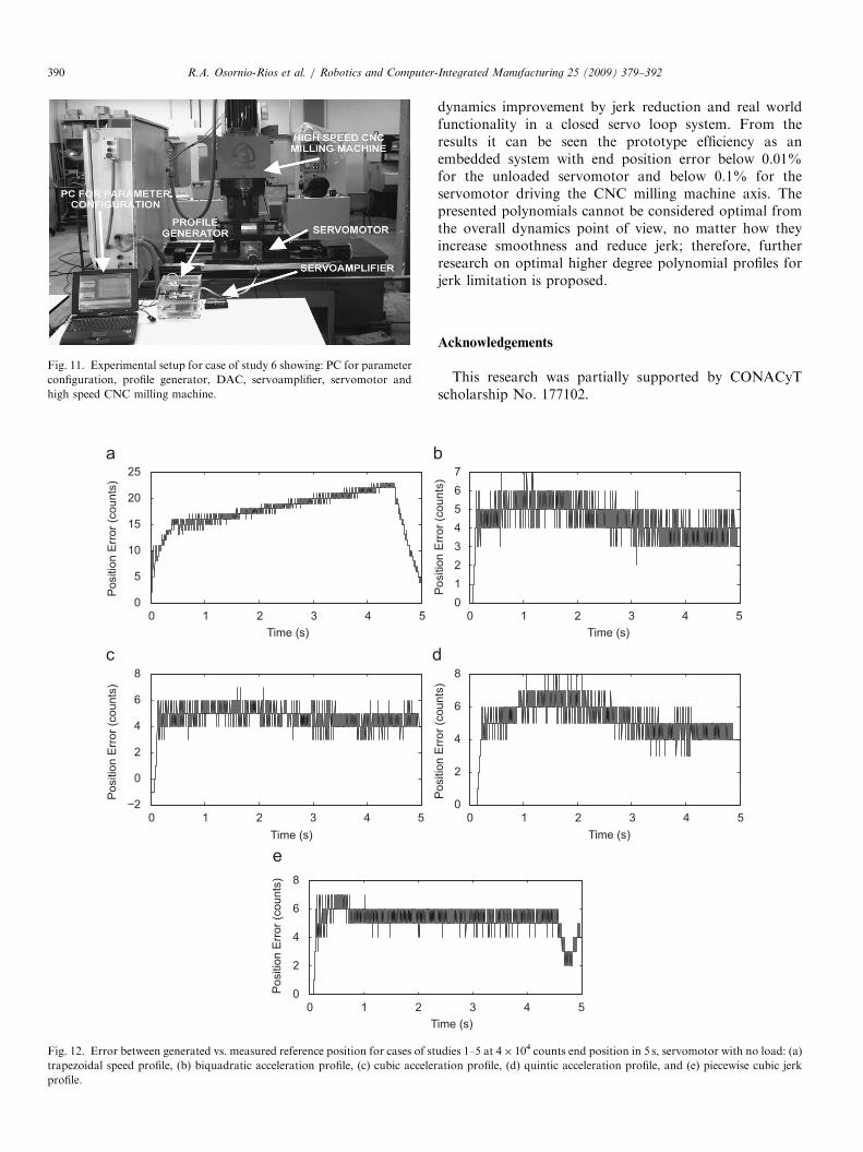
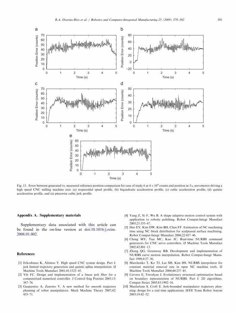
profiles, compared to the standard trapezoidal speed profile(case of study 1 used as reference), improve the systemdynamics by reducing peak jerk in more than one order ofmagnitude. The sixth case of study tests the algorithmfunctionality in operating conditions with the servomotordriving a high-speed CNC milling machine axis as shownin Fig. 11. Precision under operating conditions for theunloaded servomotor is high as shown in Fig. 12 withan end point reference error of 4 counts from an endpoint reference of 4� 104 counts for all cases, as measuredfrom the servomotor encoder. For the case of study 6with the servomotor driving the CNC milling machineaxis, the end point reference error is around 30 counts forcases 1, 4 and 5; and around 40 counts for cases 2 and 3,from an end point reference of 4� 104 counts, as shown inFig. 13.
7. Conclusions
This work presents the development of a higher degreepolynomial profile generator for CNC and roboticsapplications, aimed to improve the machinery dynamicsby jerk reduction. Jerk limitation helps reducing theservomotor and machinery stress by a smooth anddiscontinuities free overall dynamics parameters: position,velocity, acceleration and jerk. An FPGA implementation
ARTICLE IN PRESS
0 1 2 3 4 50
1
2
3
4P
ositi
on (C
ount
s)
0 1 2 3 4 5−0.2
0
0.2
0.4
0.6
0.8
1
Spe
ed (C
ount
s/s)
−4
−3
−2
−1
0
1
2
Acc
eler
atio
n (C
ount
s/s2 )
−30
−20
−10
0
10
20
30
40
Jerk
(Cou
nts/
s3 )
x104 x104
x104 x104
−0.5Time (s)
5.5 −0.5Time (s)
5.5
0 1 2 3 4 5 0 1 2 3 4 5−0.5Time (s)
5.5 −0.5Time (s)
5.5
Fig. 9. Piecewise cubic jerk profile dynamics for 4� 104 count end reference in 5 s: (a) position, (b) speed, (c) acceleration, and (d) jerk.
Fig. 10. Experimental setup for cases of studies 1–5 showing: profile
generator, DAC, servoamplifier and servomotor.
R.A. Osornio-Rios et al. / Robotics and Computer-Integrated Manufacturing 25 (2009) 379–392388
of the profile generator is developed, along with comple-mentary digital structures, to show the benefits of using thistechnology for embedded systems.
Previous works reported higher degree polynomialprofile computations, nevertheless, those techniques arecomputationally intensive, which made them unsuitable foron-line implementation due to their hardware requirements
are high increasing the costs. The contribution of thepresent work is to present a costless implementation of ahigh efficient algorithm for polynomial evaluation which iseasily implemented into FPGA while preserving therequired precision of the overall process.From the digital implementation point of view, FPGA
technology has proven to be ideally suited for the task.SOC approach is natural in FPGA where the polynomialprofile generator, along with complementary structuressuch as: PID, DAC driver, timer, error adder, feedbackencoder counter and PC interface, are implementedtogether in parallel. The parallel architecture ensures thaton-line application could be achieved for the embeddedsystem developed. For the cases of study, a 1� 10�3 sservo loop update time is used, which gives no problem tothe computation load of the FPGA and a 10� 10�6 sservo loop update time can be produced with minimalchanges to the same structure (i.e. modify the timersettings via PC interface). Finally, the Spartan-3 familyFPGA used in the development is a very low costunit (under US $10.00) which is a self-contained SOCsystem for not only de profile generator but PID, DACdriver, etc.It is to be noted that the polynomial profiles of the cases
of study presented in this work were proposed to show the
ARTICLE IN PRESS
Table 1
Peak parameter dynamics for cases of studies 1–5 at an end position of 1� 104 counts in 1 s
Profiles results (1� 104 counts position hardware generation in 1 s)
Parameter Trapezoidal speed Biquadratic acceleration Cubic acceleration Quintic acceleration Piecewise cubic jerk
End position (counts) 1� 104 1� 104 1� 104 1� 104 1� 104
Top speed (count/s) 1.11� 104 2� 104 1.875� 104 4.3� 104 11.75� 104
Maximum acceleration (count/s2) 11.2� 104 6� 104 5.77� 104 28.7� 104 11� 104
Maximum deceleration (count/s2) 11.2� 104 6� 104 5.77� 104 28.7� 104 11� 104
Peak jerk (count/s3) 112� 106 47.9� 104 59.82� 104 330� 104 170� 104
720� 104
Table 2
Peak parameter dynamics for cases of studies 1–5 at an end position of 2� 104 counts in 2 s
Profiles results (2� 104 counts position hardware generation in 2 s)
Parameter Trapezoidal speed Biquadratic acceleration Cubic acceleration Quintic acceleration Piecewise cubic jerk
End position (counts) 2� 104 2� 104 2� 104 2� 104 2� 104
Top speed (count/s) 1.11� 104 2� 104 1.875� 104 8.542� 104 1.175� 104
Maximum acceleration (count/s2) 5.6� 104 3� 104 2.88� 104 57.3� 104 5.5� 104
Maximum deceleration (count/s2) 5.6� 104 3� 104 2.88� 104 57.3� 104 11� 104
Peak jerk (count/s3) 56� 106 12� 104 15� 104 62.5� 104 42.4� 104
159.8� 104
Table 3
Peak parameter dynamics for cases of studies 1–5 at an end position of 4� 104 counts in 5 s
Profiles results (4� 104 counts position hardware generation in 5 s)
Parameter Trapezoidal speed Biquadratic acceleration Cubic acceleration Quintic acceleration Piecewise cubic jerk
End position (counts) 4� 104 4� 104 4� 104 4� 104 4� 104
Top speed (count/s) 8.8� 104 1.5� 104 1.5� 104 17.09� 104 9.411� 103
Maximum acceleration (count/s2) 1.78� 104 9.6� 103 9.24� 103 1.8� 104 1.76� 104
Maximum deceleration (count/s2) 1.78� 104 9.6� 103 9.24� 103 1.8� 104 3.5� 104
Peak jerk (count/s3) 18� 106 1.535� 104 1.92� 104 12.5� 106 5.43� 104
21.73� 104
Table 4
FPGA implementation resources
Time and device results (polynomial profiles SPARTAN 3 FPGA 3s200ft256-4)
Parameter Trapezoidal Biquadratic Cubic Quintic Piecewise cubic
Polynomial profile generator only
Number of slices 797 of 1920 795 of 1920 1073 of 1920 1118 of 1920 1508 of 1920
Number of slice flip flops 556 of 3840 721 of 3840 844 of 3840 1069 of 3840 1126 of 3840
Number of four input LUTs 1438 of 3840 1363 of 3840 1846 of 3840 2002 of 3840 2529 of 3840
Overall average FPGA usage (%) 29 30 39 43 53
Polynomial profile generator and complementary structures
Number of slices 1241 of 1920 1271 of 1920 1340 of 1920 1632 of 1920 1803 of 1920
Number of slice flip flops 1186 of 3840 1356 of 3840 1441 of 3840 1634 of 3840 1540 of 3840
Number of four input LUTs 2184 of 3840 2227 of 3840 2384 of 3840 2533 of 3840 2730 of 3840
Overall average FPGA usage (%) 48 50 54 60 63.2
R.A. Osornio-Rios et al. / Robotics and Computer-Integrated Manufacturing 25 (2009) 379–392 389
ARTICLE IN PRESS
Fig. 11. Experimental setup for case of study 6 showing: PC for parameter
configuration, profile generator, DAC, servoamplifier, servomotor and
high speed CNC milling machine.
0 1 2 3 4 50
5
10
15
20
25
Time (s)
Pos
ition
Err
or (c
ount
s)
0 1 2 3 4 5−2
0
2
4
6
8
Time (s)
Pos
ition
Err
or (c
ount
s)
0 1 20
2
4
6
8
T
Pos
ition
Err
or (c
ount
s)
Fig. 12. Error between generated vs. measured reference position for cases of st
trapezoidal speed profile, (b) biquadratic acceleration profile, (c) cubic acceler
profile.
R.A. Osornio-Rios et al. / Robotics and Computer-Integrated Manufacturing 25 (2009) 379–392390
dynamics improvement by jerk reduction and real worldfunctionality in a closed servo loop system. From theresults it can be seen the prototype efficiency as anembedded system with end position error below 0.01%for the unloaded servomotor and below 0.1% for theservomotor driving the CNC milling machine axis. Thepresented polynomials cannot be considered optimal fromthe overall dynamics point of view, no matter how theyincrease smoothness and reduce jerk; therefore, furtherresearch on optimal higher degree polynomial profiles forjerk limitation is proposed.
Acknowledgements
This research was partially supported by CONACyTscholarship No. 177102.
0 1 2 3 4 501234567
Time (s)
Pos
ition
Err
or (c
ount
s)
0 1 2 3 4 50
2
4
6
8
Time (s)
Pos
ition
Err
or (c
ount
s)
3 4 5ime (s)
udies 1–5 at 4� 104 counts end position in 5 s, servomotor with no load: (a)
ation profile, (d) quintic acceleration profile, and (e) piecewise cubic jerk
ARTICLE IN PRESS
0 1 2 3 4 50
10203040506070
Time (s)
Pos
ition
Err
or (c
ount
s)
0 1 2 3 4 5−20
0
20
40
60
80
Time (s)
0 1 2 3 4 5Time (s)
0 1 2 3 4 5Time (s)
0 1 2 3 4 5Time (s)
Pos
ition
Err
or (c
ount
s)0
10203040506070
Pos
ition
Err
or (c
ount
s)
0
10
20
30
40
50
Pos
ition
Err
or (c
ount
s)
0102030405060
Pos
ition
Err
or (c
ount
s)
Fig. 13. Error between generated vs. measured reference position comparison for case of study 6 at 4� 104 counts end position in 5 s, servomotor driving a
high speed CNC milling machine axis: (a) trapezoidal speed profile, (b) biquadratic acceleration profile, (c) cubic acceleration profile, (d) quintic
acceleration profile, and (e) piecewise cubic jerk profile.
R.A. Osornio-Rios et al. / Robotics and Computer-Integrated Manufacturing 25 (2009) 379–392 391
Appendix A. Supplementary materials
Supplementary data associated with this article canbe found in the on-line version at doi:10.1016/j.rcim.2008.01.002.
References
[1] Erkorkmaz K, Altintas Y. High speed CNC system design. Part I:
jerk limited trajectory generation and quintic spline interpolation. IJ
Machine Tools Manufact 2001;41:1323–45.
[2] Yih FC. Design and implementation of a linear jerk filter for a
computerized numerical controller. J Control Eng Practice 2005;13:
567–76.
[3] Gasparetto A, Zanotto V. A new method for smooth trajectory
planning of robot manipulators. Mech Machine Theory 2007;42:
455–71.
[4] Yang Z, Xi F, Wu B. A shape adaptive motion control system with
application to robotic polishing. Robot Comput-Integr Manufact
2005;21:355–67.
[5] Heo EY, Kim DW, Kim BH, Chen FF. Estimation of NC machining
time using NC block distribution for sculptured surface machining.
Robot Comput-Integr Manufact 2006;22:437–46.
[6] Cheng MY, Tsai MC, Kuo JC. Real-time NURBS command
generators for CNC servo controllers. IJ Machine Tools Manufact
2002;42:801–13.
[7] Zhang QG, Greenway RB. Development and implementation of
NURBS curve motion interpolation. Robot Comput-Integr Manu-
fact 1998;4:27–36.
[8] Marchenko T, Ko TJ, Lee SH, Kim HS. NURBS interpolator for
constant material removal rate in open NC machine tools. IJ
Machine Tools Manufact 2004;44:237–45.
[9] Cervera E, Trevelyan J. Evolutionary structural optimisation based
on boundary representation of NURBS. Part I: 2D algorithms.
Comput Struct 2005;83:1902–16.
[10] Macfarlane S, Croft E. Jerk-bounded manipulator trajectory plan-
ning: design for a real time applications. IEEE Trans Robot Autom
2003;19:42–52.

ARTICLE IN PRESSR.A. Osornio-Rios et al. / Robotics and Computer-Integrated Manufacturing 25 (2009) 379–392392
[11] Jeon WJ, Kim YK. FPGA based acceleration and deceleration circuit
for industrial robots and CNC machine tools. Mechatronics
2002;12:635–42.
[12] Jimeno A, Sanchez JL, Mora H, Mora J, Garcıa JM. FPGA-based
tool path computation: an application for shoe last machining on
CNC lathes. Comput Ind 2006;57:103–11.
[13] Chen JS, Lin IN. Toward the implementation of an ultrasonic motor
servo drive using FPGA. Mechatronics 2002;12:511–24.
[14] Girau B, Boumaza A. Embedded harmonic control for dynamic
trajectory planning on FPGA. In: Proceedings of the IASTED
conference on artificial intelligence and applications. Innsbruck,
Austria; 2007. p. 12–4.
[15] Hamming RY. Numerical methods for scientists and engineers. 2nd
ed. New York: Dover Publications; 1986.
[16] Osornio-Rios RA, Romero-Troncoso RJ, Herrera-Ruiz G, Catane-
da-Miranda R. Computationally efficient parametric analysis of
discrete-time polynomial based acceleration—deceleration profile
generation for industrial robotics and CNC machinery. Mechatronics
2007;17:511–23.
[17] Xilinx Corporation. Spartan-3 family FPGAs data sheet. Xilinx
Corporation; 2005.
[18] Burr-Brown Corporation. TLV5636 data sheet. Burr-Brown Cor-
poration, A division of Texas Instruments Inc.; 1998.


