
Flow Monitors,Flow Meters,
Excess Flow Valves
www.ChemTec.com 1-800-222-2177
Table of Contents
LPH Series.................................. FS Series.................................... 125 Series.................................. 125 BP Series............................. 500 BP Series.............................LCA Series..................................FAV Series.................................. CCM Series.................................MAO 125/250 Series.................... 500 Series...........................EFV Series..................................EFV MRS Series..........................HPEFV Series..............................TEFLON Products........................LPH UHP Series..........................
01 03 05 07 09 11 13 15 171921 23 27 29 30
3077 S.W. 13th Drive Deerfield Beach, FL 33442 P (954) 428 8259 (800) 222 2177 F(954) 428 8745 www.ChemTec.com
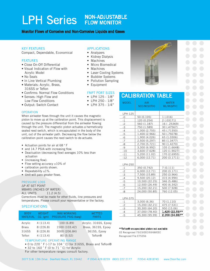
LPH Series NON-ADJUSTABLEFLOW MONITOR
Monitor Flows of Corrosive and Non-Corrosive Liquids and Gases
KEY FEATURESCompact, Dependable, Economical
FEATURES• Close On-Off Differential• Visual Indication of Flow with Acrylic Model• No Seals• In Line Vertical Plumbing • Materials: Acrylic, Brass, 316SS or Teflon• Confirms: Normal Flow Conditions • Senses: High Flow and Low Flow Conditions• Output: Switch Contact
APPLICATIONS• Analyzers• Kidney Dialysis • Machines• Micro Biomedical • Machines• Laser Cooling Systems • Bubbler Systems • Pollution Sampling • Equipment
FNPT PORT SIZES• LPH 125 - 1/8” • LPH 250 - 1/8” • LPH 375 - 1/4”
OPERATIONWhen air/water flows through the unit it causes the magnetic piston to move up at the calibration point. This displacement is caused by the pressure differential from the air/water flowing through the unit. The magnetic piston actuates a hermetically sealed reed switch, which is encapsulated in the body of the unit, out of the air/water path. Decreasing the flow below the calibration point causes the reed switch to de-actuate.
• Actuation points for air at 68 ° F• and 14.7 PSIA with increasing flow. • Deactuation (decreasing flow) averages 10% less than actuation• (increasing flow). • Flow setting accuracy ±10% of • calibration points shown.• Repeatability ±1%.• Unit will pass greater flows.
PRESSURE LOSS∆P AT SET POINTMBARS (INCHES OF WATER)ALL UNITS 11.2 (4.5)Corrections must be made for other fluids, line pressures and temperatures. Please consult your representative or the factory.
SPECIFICATIONS
BODY MATERIAL
WEIGHTOZ. (gm)
WAX WORKINGPRESSURE PSIG (barg)
WETTEDPARTS
Acrylic
Brass
316SS
Teflon
4 (113.4)
8 (226.8)
8 (226.8)
4 (113.4)
100 (6.89)
1500 (103.42)
3000 (206.84)
80 (5.52)
Acrylic. 316SS, Epoxy
Brass, 361SS, Epoxy
361SS, Epoxy
Teflon®
3077 S.W. 13th Drive Deerfield Beach, FL 33442 P (954) 428 8259 (800) 222 2177 F(954) 428 8745 www.ChemTec.com
TEMPERATURE OPERATING RANGE• 0 to 220 ˚ F (-17 to 104 ˚ C) for 316SS, Brass and Teflon® • 32 to 160 ˚ F (0 to 71 ˚ C) for AcrylicFor other temperature ranges consult factory.
1 (.016) 2 (.03171) 16 ( .25369) 30 (.47567)45 (.71350) 50 (.79278) 65 (1.0306) 85 (1.3477) 90 (1.4270) 105 (1.6648)120 (1.9027) 170 (2.6955) 200 (3.1711)
7 (0.111) 200 (3.171)250 (3.964) 315 (4.994) 346 (5.486) 400 (6.342) 500 (7.928) 760 (12.05)
70 (1.110) 475 (7.531) 950 (15.06)1,425 (22.59)** 2,200 (34.88)**
50 (0.105)120 (0.254)560 (1.187)750 (1.589)1,300 (2.755)1,400 (2.966)1,900 (4.026)2,500 (5.297)2,700 (5.721)3,300 (6.992) 3,600 (7.628) 5,200 (11.02)6,000 (12.71)
350 (0.742)6,000 (12.71)7,500 (15.89)9,500 (20.12)10,500 (22.25)12,500 (26.49)15,200 (32.21)24,000 (50.85)
3,000 (6.36)15,200 (32.21)30,300 (64.20)37,000 (78.40) 45,300 (95.99)
LPH-125 -0-1 -2 -3 -4 -5 -6 -7 -8 -9-10 -11 -12
LPH-250 -1-2 -3 -4 -5-6 -7 -8
LPH-375 -1-2 -3 -4 -5
CALIBRATION TABLEMODEL AIR
SCC/M(SCFH)WATER
ML/M(GPH)
**Teflon® encapsulated piston not available
CE Recognized 73/23/EEC/93/68/EEC
Recognized File E75356
HOW TO ORDER ([email protected] | (800) 222-2177}
SPST SPOTSWITCH DATA
Maximum Switching Voltage
Contact Rating
Maximum Switching Current (A)
DC (V)AC (V)
DC (W)AC (VA)
DC (A)AC (A)
200150
5070
1.00.7
175120
55
.25
.25
LEADS SPST SPDT(Optional)
leads 18 in. min. from body 22
AWG, TFE insulation
leads 18 in. min. from body 24
AWG, TFE insulation• green - N.C.• blue - N.O.
• white - Common
Above Values for resistive loads only. For inductive loads, surge current and rush current. Contact protection is required, consult your local representative.SPDT UL Recognized (E47258).
3077 S.W. 13th Drive Deerfield Beach, FL 33442 P (954) 428 8259 (800) 222 2177 F(954) 428 8745 www.ChemTec.com
LPH Series NON-ADJUSTABLEFLOW MONITOR
Monitor Flows of Corrosive and Non-Corrosive Liquids and Gases
Cop
yrig
ht2
01
6
V.1
INSTALLATIONMount with the inlet port down vertically.A 10 micron filter is recommended.
LEADS UPLEADS DOWNCONDUIT
Normally OpenNormally ClosedN.O. Conduit Offset DownN.C. Conduit Offset Up
Mode Size Calibration Materials Electrical Conduit Media Switch Options
LPH 125250375
See cal.table
A Acrylic B BrassS 316SS T Teflon®
(TFE pistonstandard inTFE units)
C(MetallicBodies Only)(1/2” FNPT)
W WaterA Air
N.O.
N.C.
SPTD
DSNONO
DSNONC
DSNCNC
Single PoleSingle ThrowNormally Open
Single PoleSingle ThrowNormally Closed
Single PoleDouble Throw
Double SwitchN.O./N.O.
Double SwitchN.O./N.C.
Double SwitchN.C./N.C.
Teflon® EncapsulatedPiston (Standard inTeflon units)
Oxygen Cleaned
High TemperatureOptions 340˚F(171˚C) metallicbody only
High Voltage Switch(220 VAC)
TFE
O2
HT
HV
COMM.
N.C.
N.O.
2.00 in[50.8 mm]
1.79 in[45.4 mm]
1.13 in[28.5 mm]
0.56 in[14.2 mm]
1/2˚ FNPT
••••••
•••
•
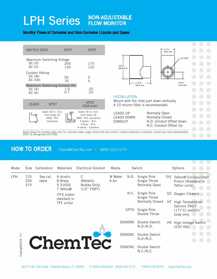
OPERATIONAs flow is established upward through the unit and contin-ues to increase, the pressure differential across the magnet-ic piston increases until it overcomes the magnetic piston’s resistance (mass). This force causes it to progress fully upward to actuate the dry reed switch. This is a snap action and occurs in the decreasing mode as well.
Actuation Points for increasing flowCalibration Accuracy ± 10 % of actuation point Deactuation (decreasing flow) averages 10 % less than actuation (increasing flow)Repeatability ± 2%Unit will pass greater flows
•••
••
0° to 228 ° F (-17 ° to 104 ° C )for Brass and Stainless Steel 32° to120° F (0° to49° C)forPVCFor other temperature ranges consult factory.
TEMPERATURE OPERATING RANGE•
•0.76 (0.20) 1.89 (0.50) 2.84 (0.75) 3.79 (1.00) 3.68 (1.50) 7.57 (2.00)
0.95 (0.25) 2.84 (0.75) 3.79 (1.00) 7.57 (2.00) 11.4 (3.00) 15.1 (4.00)
7.57 (2.00) 9.46 (2.50) 11.4(3.00) 15.1(4.00) 22.7(6.00) 32.2(8.50)
FS Series NON-ADJUSTABLEFLOW MONITOR
For Economical Monitoring of Higher Flows of Corrosice and Non-Corrosive Liquids
Non-Adjustable Flow MonitorLow MaintenanceClose On-Off DifferentialNo SealsSingle Moving PartIn Line Vertical Plumbing
Materials: 31 6S S, Bras s or PVC Con rms: Normal Flow Condition Senses: High flow orLow flow conditionsOutput: Switch Contact
APPLICATIONSLaser Cooling Systems Heat PumpsCooling Systems
KEY FEATURESEconomical Liquid Flow Sensor
SPECIFICATIONS
CALIBRATION TABLE
MODEL PVCLPM (GPM)
BRASS or 316SSLPM (GPM)
-A -B-C-D -E-F
-A -B-C-D -E-F
-A -B-C-D -E-F
FS-50
FS-75
FS-I
0.57 (0.15) 0.95 (0.25) 1.89 (0.50) 2.84 (0.75) 3.79 (1.00) 4.73 (1.25)
0.95 (0.25) 1.89 (0.50) 3.79(1.00) 5.68 (1.50) 7.57 (2.00) 9.46 (2.50)
1.89 (0.50) 3.79 (1.00) 7.57(2.00) 11.4(3.00) 15.1(4.00) 21.8(5.75)
UL & CE recognized
PRESSURE LOSS
∆P TO ATMOSPHERE at Set Point PSID (BARD)
3077 S.W. 13th Drive Deerfield Beach, FL 33442 P (954) 428 8259 (800) 222 2177 F(954) 428 8745 www.ChemTec.com
WATER PVC UNITSALL SET POINT S... 0.50 (0. 034)
METAL UNITSALL SET POINT S... 1.00 (0. 069)
WEIGHTMATERIAL
MAX WORKING
PRESSURE PSIG (barg)
WETTED
PARTS
PVC
Brass
316SS
PVC
Brass
316S
PVC
Brass
316SS
1⁄2” 0.2lb
1⁄2” 0.7lb
1⁄2” 0.7lb
3⁄4” 0.3lb
3⁄4” 1.0lb
3⁄4” 1.0lb
1” 0.4lb
1” 1.2lb
1” 1.2lb
100 (6.89)
250(17.22)
500(34.45)
100 (6.89)
250(17.22)
500(34.45)
100 (6.89)
250(17.22)
500(34.45)
PVC, Epoxy
Brass, Epoxy
316SS, Epoxy
PVC, Epoxy
Brass, Epoxy
316SS, Epoxy
PVC, Epoxy
Brass, Epoxy
316SS, Epoxy
®
Recognized 73/23/EEC/93/68/EEC
Recognized File E75356
*Consult Factory
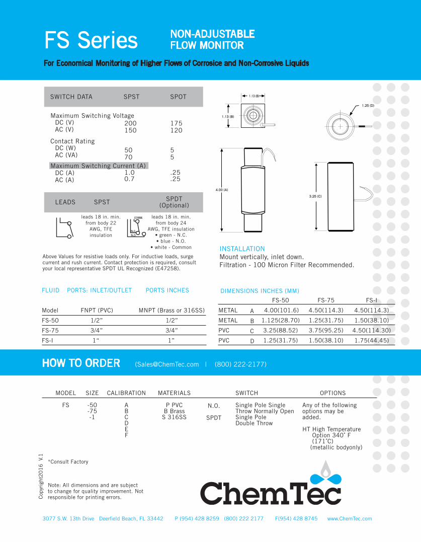
PORTS: INLET/OUTLET PORTS INCHES
FNPT (PVC) MNPT (Brass or 316SS)
1/2” 1/2”
3/4” 3/4”
1“ 1”
DIMENSIONS INCHES (MM)
FS-75
4.50(114.3)
1.25(31.75)
3.75(95.25)
1.50(38.10)
FS-50
4.00(101.6)
1.125(28.70)
3.25(88.52)
1.25(31.75)
METAL
METAL
PVC
PVC
A
B
C
D
OPTIONS
Any of the following options may be added.
HT High Temperature Option 340˚ F (171˚C) (metallic bodyonly)
FS Series NON-ADJUSTABLEFLOW MONITOR
For Economical Monitoring of Higher Flows of Corrosice and Non-Corrosive Liquids
3077 S.W. 13th Drive Deerfield Beach, FL 33442 P (954) 428 8259 (800) 222 2177 F(954) 428 8745 www.ChemTec.com
Cop
yrig
ht2
01
6
V.1
Note: All dimensions and are subject to change for quality improvement. Not responsible for printing errors.
FLUID
Model
FS-50
FS-75
FS-I
FS-I
4.50(114.3)
1.50(38.10)
4.50(114.30)
1.75(44.45)
HOW TO ORDER ([email protected] | (800) 222-2177)
MODEL
FS
SIZE
-50-75-1
CALIBRATION
ABCDEF
MATERIALS
P PVCB Brass
S 316SS
N.O.
SPDT
SWITCH
Single Pole Single Throw Normally Open Single PoleDouble Throw
SPST SPOTSWITCH DATA
Maximum Switching Voltage
Contact Rating
Maximum Switching Current (A)
DC (V)AC (V)
DC (W)AC (VA)
DC (A)AC (A)
200150
5070
1.00.7
175120
55
.25
.25
LEADS SPST SPDT(Optional)
leads 18 in. min. from body 22
AWG, TFE insulation
leads 18 in. min. from body 24
AWG, TFE insulation• green - N.C.• blue - N.O.
• white - Common
Above Values for resistive loads only. For inductive loads, surge current and rush current. Contact protection is required, consult your local representative SPDT UL Recognized (E47258).
COMM.
N.C.
N.O.
1.13 (B)
1.13 (B)
1.25 (D)
4.00 (A)
3.25 (C)
INSTALLATIONMount vertically, inlet down.Filtration - 100 Micron Filter Recommended.

1 (0.016)500 (7.93)
1/8”
Telfon® Brass, Epoxy
316SS, Epoxy
FEATURES• Broad Range of Adjustability • Compact Size• High Resolution• Materials:316SS, Brass or Teflon®• Confirms: Normal Flow Conditions• Senses: High Flow and Low Flow Conditions • Output: Switch Contact
APPLICATIONS• Welding Systems • Analyzers• Vacuum Systems • Cooling Systems • Chillers• Biomedical Instruments • Process Flows
OPERATIONA magnetic piston is suspended by therepulsion of a fixed magnet. When fluid flows through the unit it causes the magneticpiston to move against the repulsion of the fixed magnet. The magnet piston actuates anencapsulated hermetically-sealed reed switchout of the fluid path. Decreasing the flow belowthe calibration point causes the reed switch to de-actuate. Set point is adjustable.
• Actuation Points for air at 68° F and 14.7 PSIA with increasing flow • Deactuation (decreasing flow) averages 30% less than actuation (increasing flow)• Repeatability ±2%• Unit will pass greater flows
Corrections must be made for other fluids, linepressure and temperatures. Please consult your representative or the factory.
3077 S.W. 13th Drive Deerfield Beach, FL 33442 P (954) 428 8259 (800) 222 2177 F(954) 428 8745 www.ChemTec.com
125 Series STANDARD UNOBTRUSIVEADJUSTABLE FLOW MONITOR
Monitor Flows of Corrosive and Non-Corrosive Liquids and Gases
CALIBRATION RANGEMODEL AIR
SCC/M(SCFH)WATER
ML/M(GPH)
PRESSURE LOSS∆P TO ATMOSPHERE
MBARS (Inches of Water)
SPECIFICATIONS
WEIGHTOZ. (gm)
BODYMATERIAL
MAX WORKINGPRESSURE PSIG (barg)
WETTEDPARTS
PORTSFNPT
WATER FLOWRATEML/M (GPH)
∆P TO ATMOSPHEREMBARS (Inches of Water)
AIR FLOWRATECC/M (SCFH)
SEAL
Minimum Maximum
125 30 (0.063) 16,000 (33.90)
30 (.064) 310 (.657)
1500 (3.178) 16000 (33.9)
1.0 (0.016) 30 (0.48)
300 (4.76) 500 (7.93)
8.71 (3.50) 25.8 (10.38) 29.7 (11.92) 63.8 (25.63)
Teflon® Brass
316SS
4(113.4) 12 (340.2) 12 (340.2)
80(5.52) 1500 (103.42) 3000 (206.84)
Teflon® Viton® Viton®
KEY FEATURESBest for Applications where the Ratio (Normal Flow/ Set Point) is 10:1 or Greater, Minimal Pressure Drop.
®
Recognized 73/23/EEC/93/68/EEC
Recognized File E75356
TEMPERATURE OPERATING RANGE• 0° to 220° F (-17° to 104° C ) For other temperature ranges consult factory.
TFE
O2
HT
KZ
EPR
BN
FP*Consult factory **Standard with Teflon® unit®Viton - E.I. Dupont & Co®Teflon - E.I. Dupont & Co ®Kalrez - E.I. Dupont & Co
Note: All dimensions and specifications are subject to change for quality improvement. Not responsible for printing errors.
3077 S.W. 13th Drive Deerfield Beach, FL 33442 P (954) 428 8259 (800) 222 2177 F(954) 428 8745 www.ChemTec.com
125 Series STANDARD UNOBTRUSIVEADJUSTABLE FLOW MONITOR
Monitor Flows of Corrosive and Non-Corrosive Liquids and Gases
Cop
yrig
ht2
01
6
V.1
OPTIONS
Teflon ® Encapsulated Piston**
Oxygen Cleaned
High TemperatureOptions 340˚F(171˚C) metallic body only
Kalrez ® Seals
EPR Seals
Buna N Seals
Factory Preset
HOW TO ORDER ([email protected] | (800) 222-2177)
MODEL
125
TB
316
MATERIALS
Teflon® **Brass
316SS
ELECTRICAL CONDUIT (OPTIONAL)
C(Metalic Bodies Only)
(1/2” FNPT)
SWITCH
Single Pole Single Throw Normally Open Single PoleDouble Throw
N.O.
SPDT
SPST SPOTSWITCH DATA
Maximum Switching Voltage
Contact Rating
Maximum Switching Current (A)
DC (V)AC (V)
DC (W)AC (VA)
DC (A)AC (A)
200150
5070
1.00.7
175120
55
.25
.25
LEADS SPST SPDT(Optional)
leads 18 in. min. from body 22
AWG, TFE insulation
leads 18 in. min. from body 24
AWG, TFE insulation• green - N.C.• blue - N.O.
• white - Common
Above Values for resistive loads only. For inductive loads, surge current and rush current. Contact protection is required, consult your local representative.SPDT UL Recognized (E47258).
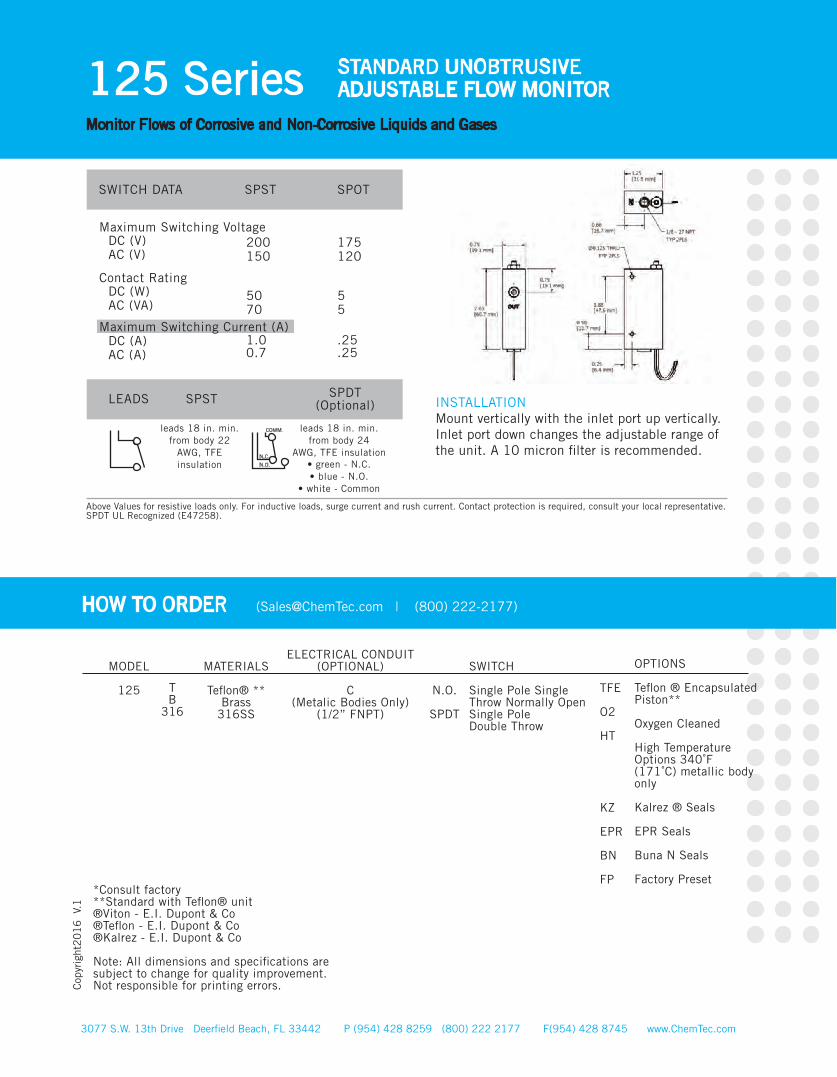
INSTALLATIONMount vertically with the inlet port up vertically.Inlet port down changes the adjustable range of the unit. A 10 micron filter is recommended.
COMM.
N.C.
N.O.

FEATURES• Broad Range of Adjustability • Compact Size• High Resolution• Close On-Off Differential• Ease of Customer Setting• Monitors Gases or Liquids• Materials:316SS, Brass or Teflon®• Confirms: Normal Flow Conditions• Senses: High Flow and Low Flow Conditions • Output: Switch Contact
APPLICATIONS• Vacuum Systems • Wet Stations• Gas Analyzers• Cooling Systems• Industrial Fluid Lines• Process Lines
3077 S.W. 13th Drive Deerfield Beach, FL 33442 P (954) 428 8259 (800) 222 2177 F(954) 428 8745 www.ChemTec.com
125 BP Series BYPASS ADJUSTABLEFLOW MONITOR
Monitor Flows of Corrosive and Non-Corrosive Liquids and Gases
3 (0.048)500 (7.93)
1/8”
Telfon® Brass, Epoxy
316SS, Epoxy
MODEL AIRSCC/M(SCFH)
WATERML/M(GPH)
PRESSURE LOSS
SPECIFICATIONS
WEIGHTOZ. (gm)
BODYMATERIAL
MAX WORKINGPRESSURE PSIG (barg)
WETTEDPARTS
PORTSFNPT
WATER FLOWRATEML/M (GPH)
∆P TO ATMOSPHEREMBARS (Inches of Water)
AIR FLOWRATECC/M (SCFH)
SEAL
Minimum Maximum
125 BP 100 (0.21) 20,000 (42.4)
100 (0.21) 5500 (11.7) 7000 (14.8)
20000 (42.4) 60000 (127.1)
3 (0.048) 200 (3.17) 400 (6.34) 500 (7.93)
950 (15.10)
1.2 (0.50)9.2 (3.71)
11.7 (4.71) 24.7 (9.93)
69.7 (28.00)
Teflon® Brass
316SS
4.4 (123.5) 16 (453.6) 16 (453.6)
100 (6.89) 1500 (103.42) 3000 (206.84)
Tflon® Viton® Viton®
5 (0.079)950 (15.105)
1/8” Minimum Maximum
125 BPHF 200 (0.42) 60,000 (127)*
KEY FEATURESBest for Applications where the Ratio (Normal Flow/Set Point) is 10:1 or less.
OPERATIONWhen no flow is present the free magneticpiston rests on the bottom of the bore, which is in a bypass off the main line. Adjustment of the orifice in the main line creates a small bypassflow to life the magnetic psiton and actuate the reed switch. When flow decreases, the pistonmoves downward and the reed switch deactuates.
• Actuation Points for air at 68° F and 14.7 PSIA with increasing flow • Deactuation (decreasing flow) averages 10% less than actuation (increasing flow)• Repeatability ±2%• Unit will pass greater flows
Corrections must be made for other fluids, linepressure and temperatures. Please consult your representative or the factory.
TEMPERATURE OPERATING RANGE• 0° to 220° F (-17° to 104° C ) For other temperature ranges consult factory.
* At 60 PSIG (4.137 BARG)
®
Recognized 73/23/EEC/93/68/EEC
Recognized File E75356
CALIBRATION RANGE
3077 S.W. 13th Drive Deerfield Beach, FL 33442 P (954) 428 8259 (800) 222 2177 F(954) 428 8745 www.ChemTec.com
125 BP Series BYPASS ADJUSTABLEFLOW MONITOR
Monitor Flows of Corrosive and Non-Corrosive Liquids and Gases
Cop
yrig
ht2
01
6
V.1
TFE
O2
HT
KZ
EPR
BN
FP
*Consult factory **Standard with Teflon® unit®Viton - E.I. Dupont & Co®Teflon - E.I. Dupont & Co ®Kalrez - E.I. Dupont & Co
Note: All dimensions and specifications are subject to change for quality improvement. Not responsible for printing errors.
OPTIONS
Teflon ® Encapsulated Piston**
Oxygen Cleaned
High TemperatureOptions 340˚F(171˚C) metallic body only
Kalrez ® Seals
EPR Seals
Buna N Seals
Factory Preset
HOW TO ORDER ([email protected] | (800) 222-2177)
MODEL
125
TB
316
MATERIALS
Teflon® **Brass316SS
ELECTRICAL CONDUIT (OPTIONAL)
C(Metalic Bodies Only)
(1/2” FNPT)
SWITCH
Single Pole Single Throw Normally Open
Single Pole Single ThrowNormally Closed(not available on conduit unit)
Single PoleDouble Throw
N.O.
N.C.
SPDT
BYPASSDESIGN
By Pass
By passHigh Flow
BP
BPHF
SPST SPOTSWITCH DATA
Maximum Switching Voltage
Contact Rating
Maximum Switching Current (A)
DC (V)AC (V)
DC (W)AC (VA)
DC (A)AC (A)
200150
5070
1.00.7
175120
55
.25
.25
LEADS SPST SPDT(Optional)
leads 18 in. min. from body 22
AWG, TFE insulation
leads 18 in. min. from body 24
AWG, TFE insulation• green - N.C.• blue - N.O.
• white - Common
Above Values for resistive loads only. For inductive loads, surge current and rush current. Contact protection is required, consult your local representative.SPDT UL Recognized (E47258).
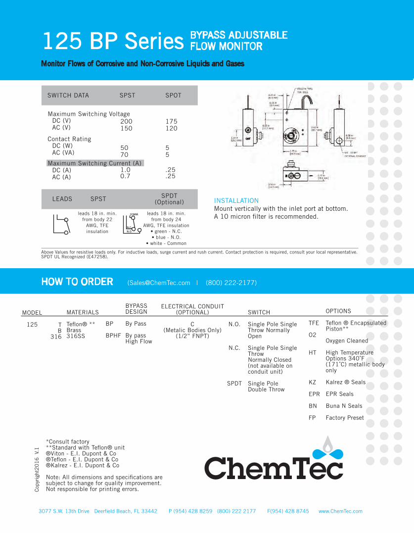
INSTALLATIONMount vertically with the inlet port at bottom.A 10 micron filter is recommended.COMM.
N.C.
N.O.
3077 S.W. 13th Drive Deerfield Beach, FL 33442 P (954) 428 8259 (800) 222 2177 F(954) 428 8745 www.ChemTec.com
500 BP Series BYPASS ADJUSTABLEFLOW MONITOR
Monitor Flows of Corrosive and Non-Corrosive Liquids and Gases
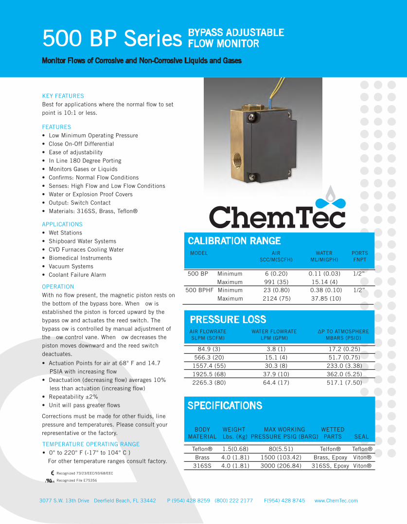
FEATURES• Low Minimum Operating Pressure • Close On-Off Differential• Ease of adjustability• In Line 180 Degree Porting• Monitors Gases or Liquids• Confirms: Normal Flow Conditions• Senses: High Flow and Low Flow Conditions • Water or Explosion Proof Covers • Output: Switch Contact• Materials: 316SS, Brass, Teflon®
APPLICATIONS• Wet Stations• Shipboard Water Systems• CVD Furnaces Cooling Water• Biomedical Instruments• Vacuum Systems• Coolant Failure Alarm 0.11 (0.03)
15.14 (4)1/2”
Telfon® Brass, Epoxy
316SS, Epoxy
MODEL AIRSCC/M(SCFH)
WATERML/M(GPH)
PRESSURE LOSS
SPECIFICATIONS
WEIGHTLbs. (Kg)
BODYMATERIAL
MAX WORKINGPRESSURE PSIG (BARG)
WETTEDPARTS
PORTSFNPT
WATER FLOWRATELPM (GPM)
∆P TO ATMOSPHEREMBARS (PSID)
AIR FLOWRATESLPM (SCFM)
SEAL
Minimum Maximum
500 BP 6 (0.20) 991 (35)
84.9 (3) 566.3 (20)
1557.4 (55) 1925.5 (68) 2265.3 (80)
3.8 (1) 15.1 (4) 30.3 (8)
37.9 (10) 64.4 (17)
17.2 (0.25)51.7 (0.75)
233.0 (3.38) 362.0 (5.25) 517.1 (7.50)
Teflon® Brass
316SS
1.5(0.68) 4.0 (1.81) 4.0 (1.81)
80(5.51) 1500 (103.42) 3000 (206.84)
Teflon® Viton® Viton®
0.38 (0.10) 37.85 (10)
1/2” Minimum Maximum
500 BPHF 23 (0.80) 2124 (75)
KEY FEATURESBest for applications where the normal flow to set point is 10:1 or less.
OPERATIONWith no flow present, the magnetic piston rests on the bottom of the bypass bore. When ow is established the piston is forced upward by the bypass ow and actuates the reed switch. The bypass ow is controlled by manual adjustment of the ow control vane. When ow decreases the piston moves downward and the reed switch deactuates.
• Actuation Points for air at 68° F and 14.7 PSIA with increasing flow • Deactuation (decreasing flow) averages 10% less than actuation (increasing flow)• Repeatability ±2%• Unit will pass greater flows
Corrections must be made for other fluids, linepressure and temperatures. Please consult your representative or the factory.
TEMPERATURE OPERATING RANGE• 0° to 220° F (-17° to 104° C ) For other temperature ranges consult factory.
®
Recognized 73/23/EEC/93/68/EEC
Recognized File E75356
CALIBRATION RANGE
NEMA IV Water Proof
NEMA VII Explosion Proof
3077 S.W. 13th Drive Deerfield Beach, FL 33442 P (954) 428 8259 (800) 222 2177 F(954) 428 8745 www.ChemTec.com
500 BP Series BYPASS ADJUSTABLEFLOW MONITOR
Monitor Flows of Corrosive and Non-Corrosive Liquids and Gases
Cop
yrig
ht2
01
6
V.1
TFE
O2
HT
KZ
EPR
BN
FP
*Consult factory **Standard with Teflon® unit®Viton - E.I. Dupont & Co®Teflon - E.I. Dupont & Co ®Kalrez - E.I. Dupont & Co
Note: All dimensions and specifications are subject to change for quality improvement. Not responsible for printing errors.
OPTIONS
Teflon ® Encapsulated Piston**
Oxygen Cleaned
High TemperatureOptions 340˚F(171˚C) metallic body only
Kalrez ® Seals
EPR Seals
Buna N Seals
Factory Preset
HOW TO ORDER ([email protected] | (800) 222-2177)
MODEL
125
TB
316
MATERIALS
Teflon® Brass316SS
COVER TPYE
W
X
SWITCH
Single Pole Single Throw Normally Open
Single PoleDouble Throw
N.O.
SPDT
BYPASSDESIGN
By Pass
By passHigh Flow
BP
BPHF
SPST SPOTSWITCH DATA
Maximum Switching Voltage
Contact Rating
Maximum Switching Current (A)
DC (V)AC (V)
DC (W)AC (VA)
DC (A)AC (A)
200150
5070
1.00.7
175120
55
.25
.25
LEADS SPST SPDT(Optional)
leads 18 in. min. from body 22
AWG, TFE insulation
leads 18 in. min. from body 24
AWG, TFE insulation• green - N.C.• blue - N.O.
• white - Common
Above Values for resistive loads only. For inductive loads, surge current and rush current. Contact protection is required, consult your local representative.SPDT UL Recognized (E47258).
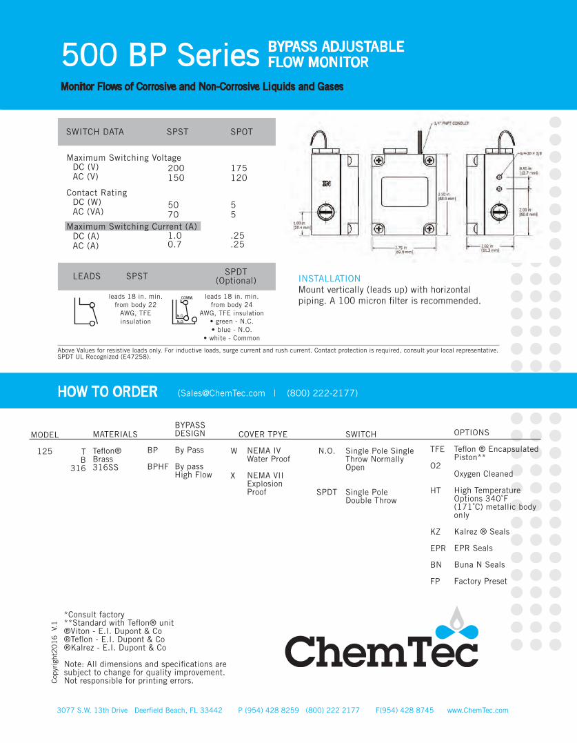
INSTALLATIONMount vertically (leads up) with horizontal piping. A 100 micron filter is recommended.COMM.
N.C.
N.O.

*-00 Available on all models - no settings
14.16 (0.5) 1416 (05)
14.16 (0.5) 1416 (05)
28.32 (1.0) 2124 (75)
114.60 (5.0) 3398
(120)
1/8”
3/8”
1/2”
3/4”
PVC, Epoxy, 316SS
Brass, Epoxy, 316SS
316SS, Epoxy
PVC, Epoxy, 316SS
Brass, Epoxy, 316SS
316SS, Epoxy
PVC, Epoxy, 316SS
Brass, Epoxy, 316SS
316SS, Epoxy
PVC, Epoxy, 316SS
Brass, Epoxy, 316SS
316SS, Epoxy
CALIBRATION RANGEMODEL AIR
SCC/M(SCFH)ADJUSTABLE
RANGEIncreasing Flow
Water LPM (GPM)
PRESSURE LOSSSPECIFICATIONS
WEIGHTLbs. (Kg)MODEL
MAX WORKINGPRESSURE PSIG (barg)
WETTEDPARTS
INLET/OUTLET
FNPT PortInches
WATER FLOWRATELPM (GPM)
∆P BARD (PSID)MODEL
LCA-250*
LCA-375*
LCA-500*
LCA-750*
0.38 - 15.1 (0.10-4.00)
1.89 - 15.1(0.50 - 4.00)
1.89 - 37.9(0.50 - 10.00)
3.79 - 56.8(1.00 - 15.00)
LCA-250/375Minimum Maximum LCA-500 Minimum Maximum LCA-750 Minimum Maximum
0.38 (0.10) 15.14 (4.0)
1.89 (0.5) 37.85 (10.0)
3.79 (1.0) 56.8 (15.0)
0.34 (0.5) 0.21 (3.0)
0.069 (1.0) 0.689 (10.0)
0.10 (1.5) 0.62 (9.0)
LCA 250P LCA-250-B LCA-250-S LCA 375P LCA-375-B LCA-375-SLCA 500P LCA-500-B LCA-500-S LCA 750P LCA-750-B LCA-750-S
.375 (.17) 1.4 (.635) 1.4 (.635) .375 (.17) 1.4 (.635) 1.4 (.635) .375 (.17) 1.4 (.635) 1.4 (.635)
.625 (.283) 1.7 (.771) 1.7 (.771)
100 (6.89) 1500 (103.42) 3000 (206.84)100 (6.89) 1500 (103.42) 3000 (206.84)100 (6.89) 1500 (103.42) 3000 (206.84)100 (6.89) 1500 (103.42) 3000 (206.84)
FACTORY PRESET FORDecreasing Flow Water LPM(GPM)*
-10 0.38 (0.10)-20 9.46 (2.50)
-30 11.46 (3.00)-10 1.89 (0.50) -20 9.46 (2.50)
-30 11.36 (3.00)-10 1.89 (0.50)
-20 18.93 (5.00)-30 28.39 (7.50)-10 3.79 (1.00)
-20 18.93 (5.00)-30 28.39 (7.50)
®
Recognized 73/23/EEC/93/68/EEC
Recognized File E75356
3077 S.W. 13th Drive Deerfield Beach, FL 33442 P (954) 428 8259 (800) 222 2177 F(954) 428 8745 www.ChemTec.com
LCA Series ADJUSTABLEFLOW MONITOR
Low Cost Flow Monitoring of Corrosive Gases and Liquids
FEATURES• Broad Range of Adjustability • Compact Size• High Resolution• Materials:316SS, Brass or Teflon®
APPLICATIONS• Welding Systems • Analyzers• Vacuum Systems • Cooling Systems
OPERATIONWhen flow is increased, the magnetic piston is forced against a bias spring. As the magnet comes near the adjustable reed switch it actuates, indicating properflow. When flow decreases the spring forces the pis - ton in the opposite direction deactuating the reed switch an indicating a reduced or no flow situation.
• All models field adjustable• Deactuation (decreasing flow) averages 40% less than actuation (increasing flow)• Repeatability ±2%• Correction must be made for attitudes other than horizontal. • Unit will pass greater flows
Corrections must be made for other fluids, linepressure and temperatures. Please consult your representative or the factory.
KEY FEATURESBest for Applications where the Ratio (Normal Flow/ Set Point) is 10:1 or Greater, Minimal Pressure Drop.
TEMPERATURE OPERATING RANGE• PVC: 32° to 120° F• 316SS and Brass: 32 to 220° F• Acrylic: 32 to 160° F For other temperature ranges consult factory.
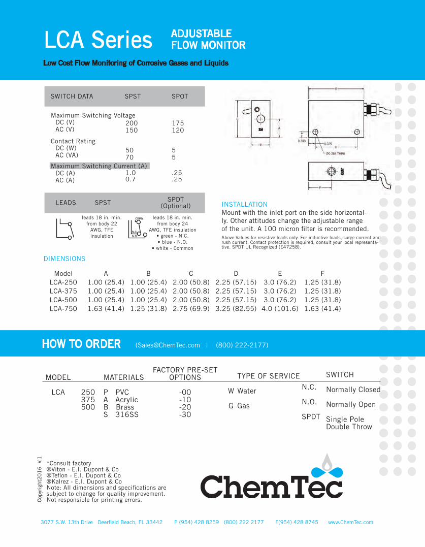
DIMENSIONS
ModelLCA-250 LCA-375 LCA-500 LCA-750
A1.00 (25.4) 1.00 (25.4) 1.00 (25.4) 1.63 (41.4)
B1.00 (25.4) 1.00 (25.4) 1.00 (25.4) 1.25 (31.8)
C2.00 (50.8) 2.00 (50.8) 2.00 (50.8) 2.75 (69.9)
D2.25 (57.15) 2.25 (57.15) 2.25 (57.15) 3.25 (82.55)
E3.0 (76.2) 3.0 (76.2) 3.0 (76.2)
4.0 (101.6)
F1.25 (31.8) 1.25 (31.8) 1.25 (31.8) 1.63 (41.4)
3077 S.W. 13th Drive Deerfield Beach, FL 33442 P (954) 428 8259 (800) 222 2177 F(954) 428 8745 www.ChemTec.com
LCA Series ADJUSTABLEFLOW MONITOR
Low Cost Flow Monitoring of Corrosive Gases and Liquids
N.C.
N.O.
SPDT
SWITCH
Normally Closed
Normally Open
Single PoleDouble Throw
HOW TO ORDER ([email protected] | (800) 222-2177)
MODEL
LCA
250375500
MATERIALS
P PVCA Acrylic B BrassS 316SS
FACTORY PRE-SETOPTIONS
-00-10-20-30
TYPE OF SERVICE
Water
Gas
W
G
Cop
yrig
ht2
01
6
V.1
SPST SPOTSWITCH DATA
Maximum Switching Voltage
Contact Rating
Maximum Switching Current (A)
DC (V)AC (V)
DC (W)AC (VA)
DC (A)AC (A)
200150
5070
1.00.7
175120
55
.25
.25
LEADS SPST SPDT(Optional)
leads 18 in. min. from body 22
AWG, TFE insulation
leads 18 in. min. from body 24
AWG, TFE insulation• green - N.C.• blue - N.O.
• white - Common
Above Values for resistive loads only. For inductive loads, surge current and rush current. Contact protection is required, consult your local representa-tive. SPDT UL Recognized (E47258).
INSTALLATIONMount with the inlet port on the side horizontal-ly. Other attitudes change the adjustable range of the unit. A 100 micron filter is recommended.
COMM.
N.C.
N.O.
*Consult factory ®Viton - E.I. Dupont & Co®Teflon - E.I. Dupont & Co ®Kalrez - E.I. Dupont & CoNote: All dimensions and specifications are subject to change for quality improvement. Not responsible for printing errors.
• Heat Pumps• Hydraulic Lifts• Water Treatment Chemicals• Industrial Analyzers
14.16 (0.5) 1416 (50)
14.16 (0.5) 1416 (50)
28.32 (1.0) 2124 (75)
141.60 (5.0) 3398 (120)
1/4”
3/8”
1/2”
3/4”
Brass, Epoxy 316SS
316SS, Epoxy
Brass, Epoxy 316SS
316SS, Epoxy
Brass, Epoxy, 316SS
316SS, Epoxy
Brass, Epoxy 316SS
316SS, Epoxy
AIRSLPM (SCFH)
PRESSURE LOSS
SPECIFICATIONS
WEIGHTLbs. (Kg)MODEL
MAX WORKINGPRESSURE PSIG (barg)
WETTEDPARTS
INLET/OUTLET
FNPT PortInches
WATER FLOWRATELPM (GPM)
∆P TOATMOSPHEREBARD (PSID)MODEL
FAV-250 Minimum Maximum FAV-375 Minimum Maximum FAV-500 Minimum Maximum FAV-750 Minimum Maximum
14.2 (0.50) 1416.0 (50.00)
28.32 (1.00) 2124.0 (75.00)
141.6 (5.00) 3398.0 (120.00)
FAV-250/375Minimum Maximum FAV-500 Minimum Maximum FAV-750 Minimum Maximum
0.38 (0.1) 15.14 (4.0)
1.89 (0.50) 37.85 (10.00)
3.78 (1.00) 75.70 (20.00)
0.034 (0.50) 0.21 (3.00)
0.069 (1.00) 0.69 (10.00)
0.10 (1.50) 0.62 (9.00)
FAV-250-ESB
FAV-250-ESS
FAV-375-ESB
FAV-375-ESS
FAV-500-ESB
FAV-500-ESS
FAV-750-ESB
FAV-750-ESS
1.4 (635)
1.4 (635)
1.4 (635)
1.4 (635)
1.4 (635)
1.4 (635)
1.7 (771)
1.7 (771)
1500 (103.42)
3000 (206.84)
1500 (103.42)
3000 (206.84)
1500 (103.42)
3000 (206.84)
1500 (103.42)
3000 (206.84)
WATERLPM (GPM)
0.38 (0.1) 15.14 (4.0)
0.38 (0.1) 15.14 (4.0)
1.89 (0.5) 37.85 (10.0)
3.79 (1.0) 75.70 (20.0)
®
Recognized 73/23/EEC/93/68/EEC
Recognized File E75356
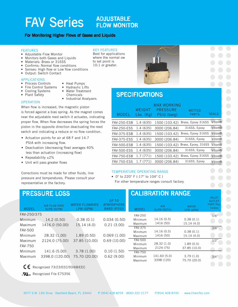
FEATURES• Adjustable Flow Monitor• Monitors both Gases and Liquids• Materials: Brass or 316SS• Confirms: Normal flow conditions• Senses: High flow or Low flow conditions• Output: Switch Contact
APPLICATIONS• Process Controls• Fire Control Systems• Cooling Systems • Plant Safety
OPERATIONWhen flow is increased, the magnetic pistonis forced against a bias spring. As the magnet comes near the adjustable reed switch it actuates, indicating proper flow. When flow decreases the spring forces the piston in the opposite direction deactuating the reed switch and indicating a reduce or no flow condition.
• Actuation points for air at 68 F and 14.7 PSIA with increasing flow.• Deactuation (decreasing flow) averages 40% less than actuation (increasing flow)• Repeatability ±2% • Unit will pass greater flows
Corrections must be made for other fluids, linepressure and temperatures. Please consult your representative or the factory.
KEY FEATURESBest for applications where the normal ow to set point is10:1 or greater.
CALIBRATION RANGE
TEMPERATURE OPERATING RANGE• 0° to 220° F (-17° to 104° C ) For other temperature ranges consult factory.
SEALS
Viton®
Viton®
Viton®
Viton®
Viton®
Viton®
Viton®
Viton®
3077 S.W. 13th Drive Deerfield Beach, FL 33442 P (954) 428 8259 (800) 222 2177 F(954) 428 8745 www.ChemTec.com
FAV Series ADJUSTABLEFLOW MONITOR
For Monitoring Higher Flows of Gases and Liquids
MODELAIR FLOW RATESLPM (SCFM)
3077 S.W. 13th Drive Deerfield Beach, FL 33442 P (954) 428 8259 (800) 222 2177 F(954) 428 8745 www.ChemTec.com
FAV Series ADJUSTABLEFLOW MONITOR
For Monitoring Higher Flows of Gases and Liquids
Cop
yrig
ht2
01
6
V.1
HOW TO ORDER ([email protected] | (800) 222-2177)
HT
KZ
EPR
BN
OPTIONS
High TemperatureOptions 340˚F(171˚C) metallic body only
Kalrez ® Seals
EPR Seals
Buna N Seals
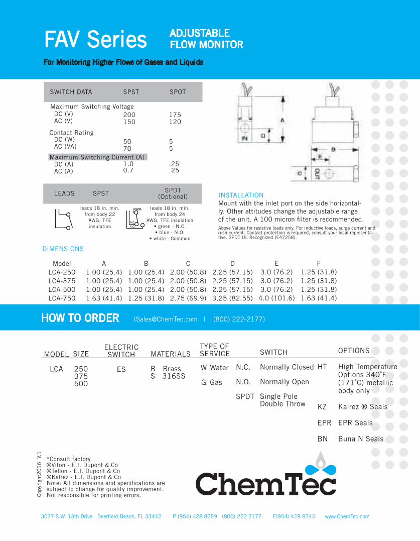
DIMENSIONS
ModelLCA-250 LCA-375 LCA-500 LCA-750
A1.00 (25.4) 1.00 (25.4) 1.00 (25.4) 1.63 (41.4)
B1.00 (25.4) 1.00 (25.4) 1.00 (25.4) 1.25 (31.8)
C2.00 (50.8) 2.00 (50.8) 2.00 (50.8) 2.75 (69.9)
D2.25 (57.15) 2.25 (57.15) 2.25 (57.15) 3.25 (82.55)
E3.0 (76.2) 3.0 (76.2) 3.0 (76.2)
4.0 (101.6)
F1.25 (31.8) 1.25 (31.8) 1.25 (31.8) 1.63 (41.4)
Contact Rating
Maximum Switching Current (A)
DC (V)AC (V)
DC (W)AC (VA)
DC (A)AC (A)
200150
5070
1.00.7
175120
55
.25
.25
LEADS SPST SPDT(Optional)
leads 18 in. min. from body 22
AWG, TFE insulation
leads 18 in. min. from body 24
AWG, TFE insulation• green - N.C.• blue - N.O.
• white - Common
Above Values for resistive loads only. For inductive loads, surge current and rush current. Contact protection is required, consult your local representa-tive. SPDT UL Recognized (E47258).
INSTALLATIONMount with the inlet port on the side horizontal-ly. Other attitudes change the adjustable range of the unit. A 100 micron filter is recommended.
COMM.
N.C.
N.O.
SPST SPOTSWITCH DATA
Maximum Switching Voltage
N.C.
N.O.
SPDT
SWITCH
Normally Closed
Normally Open
Single PoleDouble Throw
MODEL
LCA
250375500
MATERIALS
B BrassS 316SS
ELECTRICSWITCH
ES Water
Gas
W
G
*Consult factory ®Viton - E.I. Dupont & Co®Teflon - E.I. Dupont & Co ®Kalrez - E.I. Dupont & CoNote: All dimensions and specifications are subject to change for quality improvement. Not responsible for printing errors.
SIZETYPE OF SERVICE

3077 S.W. 13th Drive Deerfield Beach, FL 33442 P (954) 428 8259 (800) 222 2177 F(954) 428 8745 www.ChemTec.com
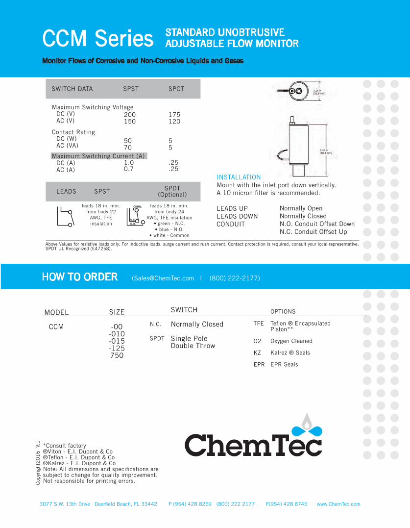
CCM Series STANDARD UNOBTRUSIVEADJUSTABLE FLOW MONITOR
Monitor Flows of Corrosive and Non-Corrosive Liquids and Gases
1 (0.016) 5 (0.08)
8 (0.13) 180 (2.9)
20 (0.32) 370 (5.9)
65 (1.03) 500 (7.9)
PVC, Epoxy
CALIBRATION RANGE
MODELAIR
SCC/M(SCFH)
PRESSURE LOSSSPECIFICATIONS
WEIGHTLbs. (Kg.)
BODYMATERIAL
MAX WORKINGPRESSURE PSIG (barg)
WETTEDPARTS
∆P TOATMOSPHERE
(MBARS INCHESIN WATER)
CCM-00Minimum Maximum CCM-010 Minimum Maximum CCM-015 Minimum Maximum CCM-125 Minimum Maximum
10 (.021) 150 (0.32)
150 (0.32) 1000 (2.12)
500 (1.06) 6000 (12.7)
6000 (12.7) 16000 (33.9)
PVC 6 Oz.(170.1 gm)
100 (6.89)
WATERML/M (GPH)
2.49 (1.0) 19.9 (8.0)
0.99 (0.4) 17.4 (7.0)
1.74 (0.7) 19.9 (8.0)
3.73 (1.5) 12.4 (5.0)
®
Recognized 73/23/EEC/93/68/EEC
Recognized File E75356
FEATURES• Adjustable Flow Monitor• High Resolution• Works in Very Low Flow Environments• Minimal Pressure Drop• Gas and Liquid Flow Sensor• Materials: PVC• Confirms: Normal flow conditions• Senses: high flow, low flow• Output: Switch Contact
APPLICATIONS• Gas Chromatography• Analyzers• Filter Maintenance • Metering Equipment • Corrosive Chemicals• Gas Generators
OPERATIONWith no flow present, the magnetic piston is held at the ow tube inlet by magnetic repulsion of the fixed magnet at the opposite end. As flow is established the piston is displaced toward the magnetic end plug and a major portion of the flow is bypassed through the flow tube orifce into the annular space. At the adjustment point the magnetic piston actuates the reed switch. On decreasing flow the switch deactuates.
• Actuation points for air at 68 F and 14.7 PSIA with increasing flow.• Deactuation (decreasing flow) averages 40% less than actuation (increasing flow)• Repeatability ±2%• Unit will pass greater flows
Corrections must be made for other fluids, linepressure and temperatures. Please consult your representative or the factory.
KEY FEATURESBest for Applications where the Ratio (Normal Flow/ Set Point) is 10:1 or Greater, Minimal Pressure Drop.
SEAL
Buna N
TEMPERATURE OPERATING RANGE• 32° to 140° F (0° to 60° C ) For other temperature ranges consult factory.
FLUID PORTSInlet 1/8” FNPT / Outlet 1/4” FNPT
3077 S.W. 13th Drive Deerfield Beach, FL 33442 P (954) 428 8259 (800) 222 2177 F(954) 428 8745 www.ChemTec.com
CCM Series STANDARD UNOBTRUSIVEADJUSTABLE FLOW MONITOR
Monitor Flows of Corrosive and Non-Corrosive Liquids and Gases
Cop
yrig
ht2
01
6
V.1
SPST SPOTSWITCH DATA
Maximum Switching Voltage
Contact Rating
Maximum Switching Current (A)
DC (V)AC (V)
DC (W)AC (VA)
DC (A)AC (A)
200150
5070
1.00.7
175120
55
.25
.25
LEADS SPST SPDT(Optional)
leads 18 in. min. from body 22
AWG, TFE insulation
leads 18 in. min. from body 24
AWG, TFE insulation• green - N.C.• blue - N.O.
• white - Common
Above Values for resistive loads only. For inductive loads, surge current and rush current. Contact protection is required, consult your local representative.SPDT UL Recognized (E47258).
INSTALLATIONMount with the inlet port down vertically.A 10 micron filter is recommended.
LEADS UPLEADS DOWNCONDUIT
Normally OpenNormally ClosedN.O. Conduit Offset DownN.C. Conduit Offset Up
COMM.
N.C.
N.O.
HOW TO ORDER ([email protected] | (800) 222-2177)
SWITCH
Normally Closed
Single PoleDouble Throw
MODEL
CCM
-00-010-015-125750
*Consult factory ®Viton - E.I. Dupont & Co®Teflon - E.I. Dupont & Co ®Kalrez - E.I. Dupont & CoNote: All dimensions and specifications are subject to change for quality improvement. Not responsible for printing errors.
SIZE
TFE
O2
KZ
EPR
OPTIONS
Teflon ® Encapsulated Piston**
Oxygen Cleaned
Kalrez ® Seals
EPR Seals
N.C.
SPDT

3077 S.W. 13th Drive Deerfield Beach, FL 33442 P (954) 428 8259 (800) 222 2177 F(954) 428 8745 www.ChemTec.com
MAO Series 125/250FLOW METER
Monitor Flows of Corrosive and Non-Corrosive Liquids and Gases
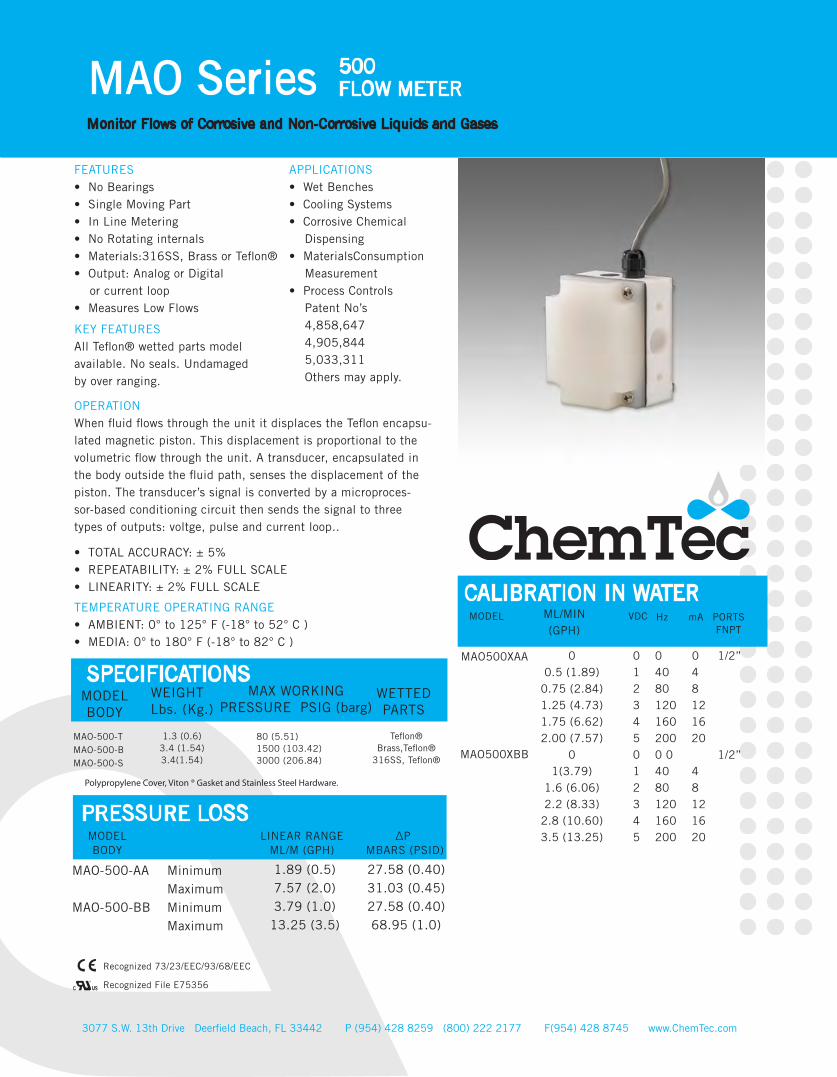
FEATURES• No Bearings• Single Moving Part• In Line Metering• No Rotating internals• Materials:316SS, Brass or Teflon®• Output: Analog or Digital or current loop• Measures Low Flows
APPLICATIONS• Wet Benches • Cooling Systems• Corrosive Chemical Dispensing • MaterialsConsumption Measurement • Process Controls Patent No’s 4,858,647 4,905,844 5,033,311 Others may apply.
OPERATIONWhen fluid flows through the unit it displaces the Teflon encapsu-lated magnetic piston. This displacement is proportional to the volumetric flow through the unit. A transducer, encapsulated in the body outside the fluid path, senses the displacement of the piston. The transducer’s signal is converted by a microproces-sor-based conditioning circuit then sends the signal to threetypes of outputs: voltge, pulse and current loop..
• TOTAL ACCURACY: ± 5%• REPEATABILITY: ± 2% FULL SCALE• LINEARITY: ± 2% FULL SCALE
KEY FEATURESAll Teflon® wetted parts model available. No seals. Undamaged by over ranging.
TEMPERATURE OPERATING RANGE• AMBIENT: 0° to 125° F (-18° to 52° C )• MEDIA: 0° to 180° F (-18° to 82° C )
PRESSURE LOSSLINEAR RANGE
ML/M (GPH)∆P
MBARS (PSID)MODELBODY
Minimum Maximum Minimum Maximum Minimum MaximumMinimum Maximum
20 (0.32) 70 (1.11) 50 (0.79)
150 (2.38) 100 (1.59) 500 (7.93) 260 (4.12)
1800 (28.54)
24.82 (0.36) 42.06 (0.61) 8.27 (0.12)
10.34 (0.15) 8.27 (0.12) 9.65 (0.14)
10.34 (0.15) 20.00 (0.29)
MAO-125-AA
MAO-125-BB
MAO-250-AA
MAO-250-BB
Teflon® Brass,Teflon®
316SS, Teflon®
SPECIFICATIONSWEIGHTLbs. (Kg.)
MODELBODY
MAX WORKINGPRESSURE PSIG (barg)
WETTEDPARTS
MAO-125/250-T MAO-125/250-B MAO-125/250-S
0.63 (0.29) 1.30 (0.59) 1.30 (0.59)
80 (5.51) 1500 (103.42) 3000 (206.84)
Polypropylene Cover, Viton ® Gasket and Stainless Steel Hardware.
MODEL VDC Hz PORTSFNPT
MAO125XAA
MAO125XBB
MAO250XAA
MAO250XBB
ML/MIN(GPH)
0 0 0 1/8” 1 40 42 80 83 120 124 160 16 5 200 20 0 0 0 1/8” 1 40 42 80 83 120 124 160 16 5 200 200 0 0 1/4” 1 40 42 80 83 120 124 160 16 5 200 200 0 0 1/4” 1 40 42 80 83 120 124 160 165 200 20
CALIBRATION IN WATER
020 (0.3170)
32.5 (0.5151) 45 (0.7133)
57.5 (0.9114) 70 (1.1095)
050 (0.7925)75 (1.1888)
100 (1.5850) 125 (1.9813) 150 (2.3775)
0 100 (1.5850)200 (3.1701) 300 (4.7551) 400 (6.3401) 500 (7.9252)
0 250 (3.9626)
638 (10.1125) 1025 (16.2466) 1413 (22.3965) 1800 (28.5306)
mA
®
Recognized 73/23/EEC/93/68/EEC
Recognized File E75356
MODEL SIZE MATERIALS FLOW RANGE
MAO 125 T Teflon® (See Chart) 250 B Brass AA S Stainless BB Steel
3077 S.W. 13th Drive Deerfield Beach, FL 33442 P (954) 428 8259 (800) 222 2177 F(954) 428 8745 www.ChemTec.com
MAO Series 125/250FLOW METER
Monitor Flows of Corrosive and Non-Corrosive Liquids and Gases
Cop
yrig
ht2
01
6
V.1
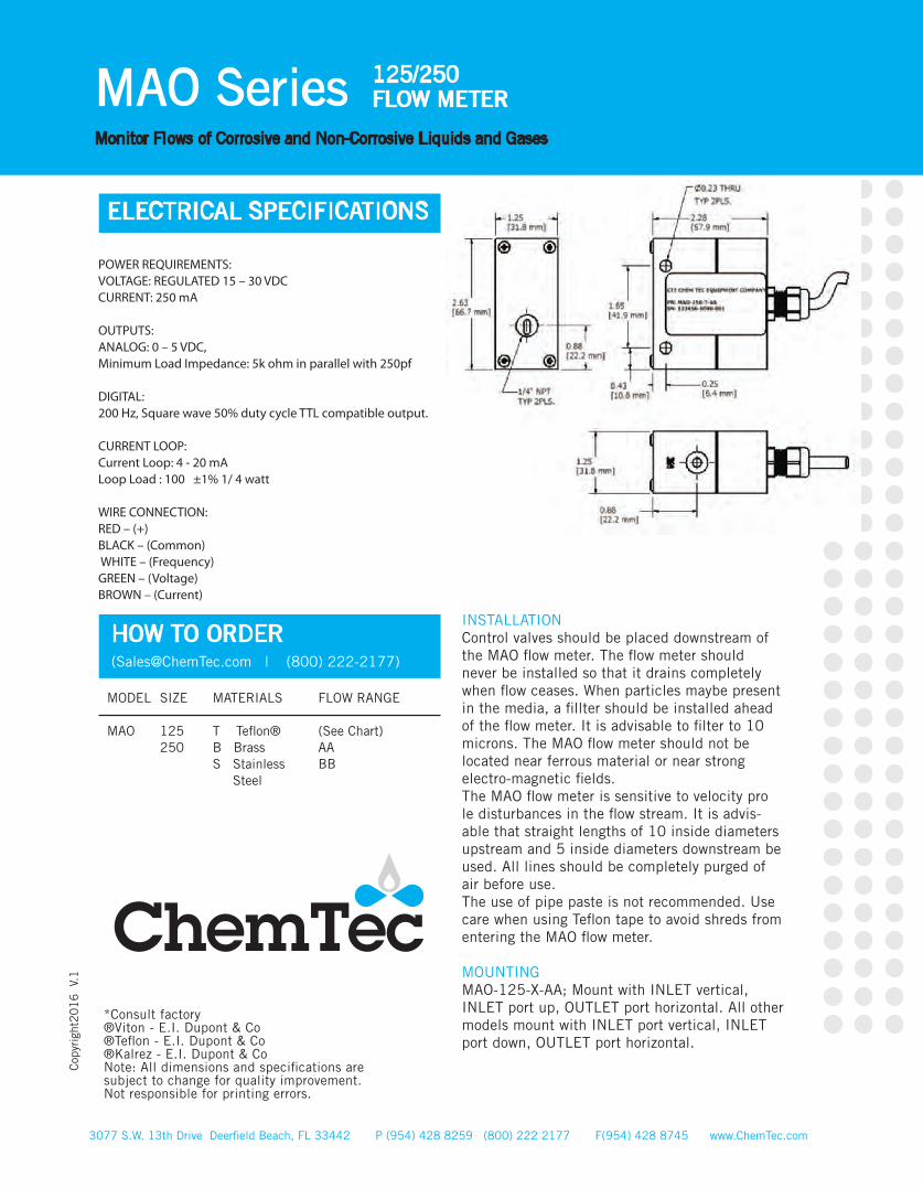
ELECTRICAL SPECIFICATIONS
POWER REQUIREMENTS:VOLTAGE: REGULATED 15 – 30 VDC CURRENT: 250 mA
OUTPUTS:ANALOG: 0 – 5 VDC,Minimum Load Impedance: 5k ohm in parallel with 250pf
DIGITAL:200 Hz, Square wave 50% duty cycle TTL compatible output.
CURRENT LOOP:Current Loop: 4 - 20 mALoop Load : 100 ±1% 1/ 4 watt
WIRE CONNECTION: RED – (+)BLACK – (Common) WHITE – (Frequency) GREEN – (Voltage) BROWN – (Current)
HOW TO ORDER ([email protected] | (800) 222-2177)
*Consult factory ®Viton - E.I. Dupont & Co®Teflon - E.I. Dupont & Co ®Kalrez - E.I. Dupont & CoNote: All dimensions and specifications are subject to change for quality improvement. Not responsible for printing errors.
INSTALLATIONControl valves should be placed downstream of the MAO flow meter. The flow meter should never be installed so that it drains completely when flow ceases. When particles maybe present in the media, a fillter should be installed ahead of the flow meter. It is advisable to filter to 10 microns. The MAO flow meter should not be located near ferrous material or near strong electro-magnetic fields.The MAO flow meter is sensitive to velocity pro le disturbances in the flow stream. It is advis-able that straight lengths of 10 inside diameters upstream and 5 inside diameters downstream be used. All lines should be completely purged of air before use.The use of pipe paste is not recommended. Use care when using Teflon tape to avoid shreds from entering the MAO flow meter.
MOUNTINGMAO-125-X-AA; Mount with INLET vertical, INLET port up, OUTLET port horizontal. All other models mount with INLET port vertical, INLET port down, OUTLET port horizontal.
FEATURES• No Bearings• Single Moving Part• In Line Metering• No Rotating internals• Materials:316SS, Brass or Teflon®• Output: Analog or Digital or current loop• Measures Low Flows
APPLICATIONS• Wet Benches • Cooling Systems• Corrosive Chemical Dispensing • MaterialsConsumption Measurement • Process Controls Patent No’s 4,858,647 4,905,844 5,033,311 Others may apply.
OPERATIONWhen fluid flows through the unit it displaces the Teflon encapsu-lated magnetic piston. This displacement is proportional to the volumetric flow through the unit. A transducer, encapsulated in the body outside the fluid path, senses the displacement of the piston. The transducer’s signal is converted by a microproces-sor-based conditioning circuit then sends the signal to threetypes of outputs: voltge, pulse and current loop..
• TOTAL ACCURACY: ± 5%• REPEATABILITY: ± 2% FULL SCALE• LINEARITY: ± 2% FULL SCALE
KEY FEATURESAll Teflon® wetted parts model available. No seals. Undamaged by over ranging.
TEMPERATURE OPERATING RANGE• AMBIENT: 0° to 125° F (-18° to 52° C )• MEDIA: 0° to 180° F (-18° to 82° C )
PRESSURE LOSSLINEAR RANGE
ML/M (GPH)∆P
MBARS (PSID)MODELBODY
Minimum Maximum Minimum Maximum
1.89 (0.5) 7.57 (2.0) 3.79 (1.0)
13.25 (3.5)
27.58 (0.40) 31.03 (0.45) 27.58 (0.40) 68.95 (1.0)
MAO-500-AA
MAO-500-BB
Teflon® Brass,Teflon®
316SS, Teflon®
SPECIFICATIONSWEIGHTLbs. (Kg.)
MODELBODY
MAX WORKINGPRESSURE PSIG (barg)
WETTEDPARTS
MAO-500-T MAO-500-B MAO-500-S
1.3 (0.6)3.4 (1.54) 3.4(1.54)
80 (5.51) 1500 (103.42) 3000 (206.84)
Polypropylene Cover, Viton ® Gasket and Stainless Steel Hardware.
MODEL VDC Hz
MAO500XAA
MAO500XBB
ML/MIN(GPH)
0 0 0 1/2” 1 40 42 80 83 120 124 160 16 5 200 20 0 0 0 1/2” 1 40 42 80 83 120 124 160 16 5 200 20
CALIBRATION IN WATER
0 0.5 (1.89)
0.75 (2.84) 1.25 (4.73) 1.75 (6.62) 2.00 (7.57)
0 1(3.79)
1.6 (6.06)2.2 (8.33)
2.8 (10.60) 3.5 (13.25)
®
Recognized 73/23/EEC/93/68/EEC
Recognized File E75356
3077 S.W. 13th Drive Deerfield Beach, FL 33442 P (954) 428 8259 (800) 222 2177 F(954) 428 8745 www.ChemTec.com
MAO Series 500FLOW METER
Monitor Flows of Corrosive and Non-Corrosive Liquids and Gases
mA PORTSFNPT
3077 S.W. 13th Drive Deerfield Beach, FL 33442 P (954) 428 8259 (800) 222 2177 F(954) 428 8745 www.ChemTec.com
MAO Series 500FLOW METER
Monitor Flows of Corrosive and Non-Corrosive Liquids and Gases
Cop
yrig
ht2
01
6
V.1
MODEL SIZE MATERIALS FLOW RANGE
MAO 500 T Teflon® (See Chart) B Brass AA S Stainless BB Steel
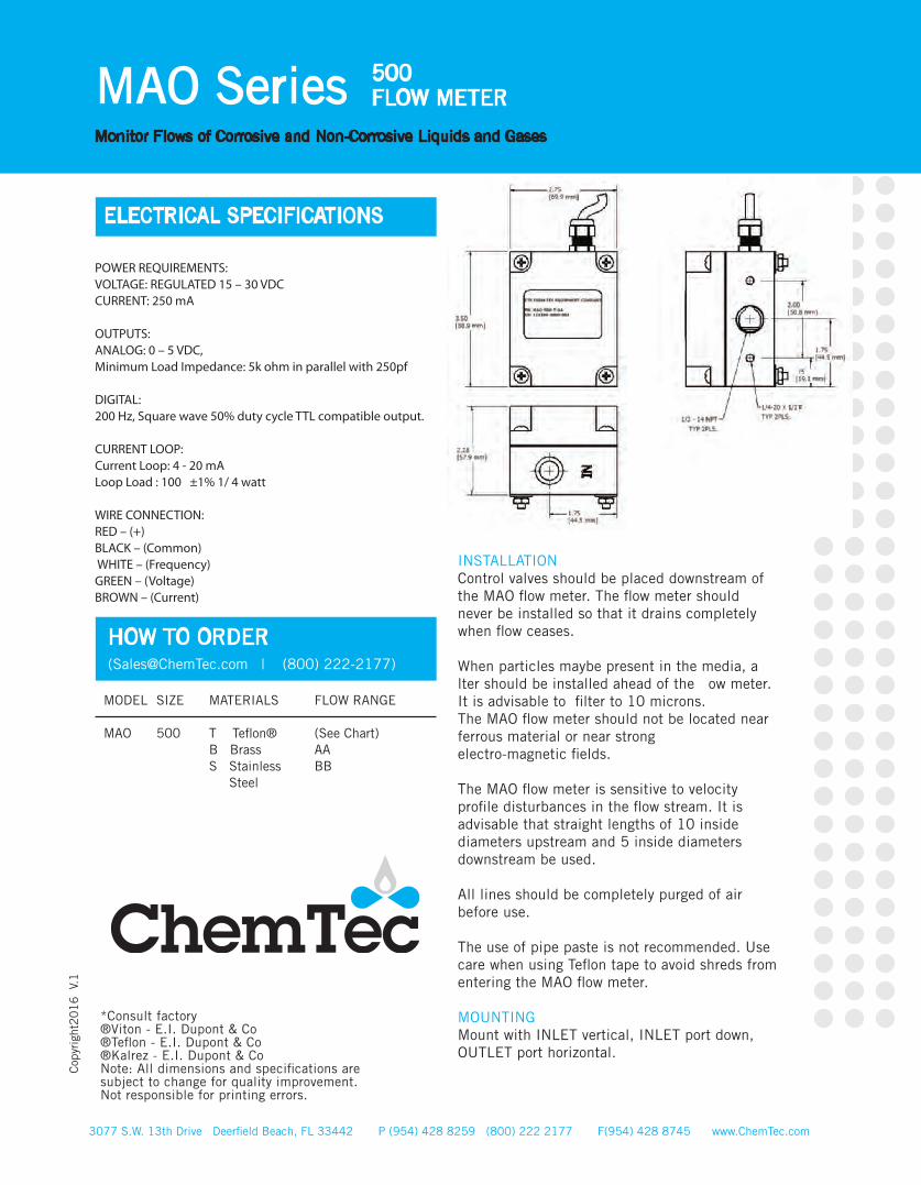
ELECTRICAL SPECIFICATIONS
POWER REQUIREMENTS:VOLTAGE: REGULATED 15 – 30 VDC CURRENT: 250 mA
OUTPUTS:ANALOG: 0 – 5 VDC,Minimum Load Impedance: 5k ohm in parallel with 250pf
DIGITAL:200 Hz, Square wave 50% duty cycle TTL compatible output.
CURRENT LOOP:Current Loop: 4 - 20 mALoop Load : 100 ±1% 1/ 4 watt
WIRE CONNECTION: RED – (+)BLACK – (Common) WHITE – (Frequency) GREEN – (Voltage) BROWN – (Current)
HOW TO ORDER ([email protected] | (800) 222-2177)
*Consult factory ®Viton - E.I. Dupont & Co®Teflon - E.I. Dupont & Co ®Kalrez - E.I. Dupont & CoNote: All dimensions and specifications are subject to change for quality improvement. Not responsible for printing errors.
INSTALLATIONControl valves should be placed downstream of the MAO flow meter. The flow meter should never be installed so that it drains completely when flow ceases.
When particles maybe present in the media, a lter should be installed ahead of the ow meter. It is advisable to filter to 10 microns.The MAO flow meter should not be located near ferrous material or near strongelectro-magnetic fields.
The MAO flow meter is sensitive to velocity profile disturbances in the flow stream. It is advisable that straight lengths of 10 inside diameters upstream and 5 inside diameters downstream be used.
All lines should be completely purged of air before use.
The use of pipe paste is not recommended. Use care when using Teflon tape to avoid shreds from entering the MAO flow meter.
MOUNTINGMount with INLET vertical, INLET port down, OUTLET port horizontal.
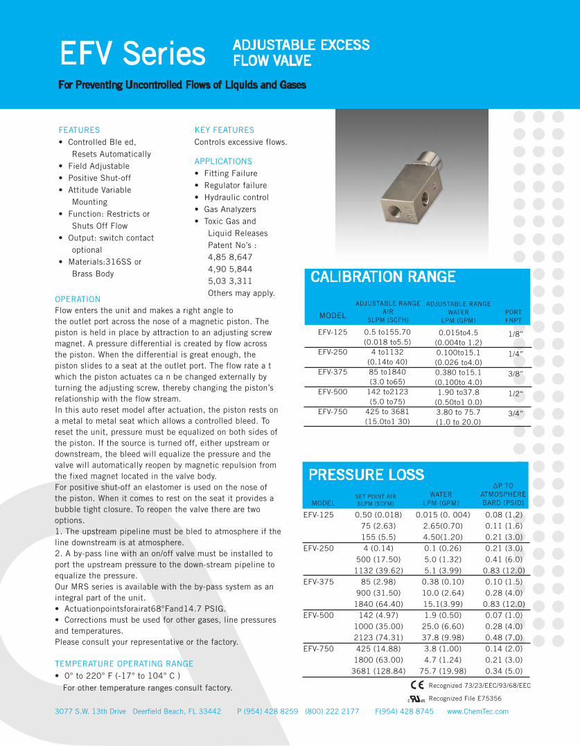
FEATURES• Controlled Ble ed, Resets Automatically • Field Adjustable• Positive Shut-off• Attitude Variable Mounting• Function: Restricts or Shuts Off Flow• Output: switch contact optional• Materials:316SS or Brass Body
APPLICATIONS• Fitting Failure • Regulator failure• Hydraulic control• Gas Analyzers• Toxic Gas and Liquid Releases Patent No’s : 4,85 8,647 4,90 5,844 5,03 3,311 Others may apply.
KEY FEATURESControls excessive flows.
PVC, EpoxyPVC 6 Oz.(170.1 gm)
Buna N
3077 S.W. 13th Drive Deerfield Beach, FL 33442 P (954) 428 8259 (800) 222 2177 F(954) 428 8745 www.ChemTec.com
EFV Series ADJUSTABLE EXCESS FLOW VALVE
For Preventing Uncontrolled Flows of Liquids and Gases
OPERATIONFlow enters the unit and makes a right angle tothe outlet port across the nose of a magnetic piston. The piston is held in place by attraction to an adjusting screw magnet. A pressure differential is created by flow across the piston. When the differential is great enough, the piston slides to a seat at the outlet port. The flow rate a t which the piston actuates ca n be changed externally by turning the adjusting screw, thereby changing the piston’s relationship with the flow stream.In this auto reset model after actuation, the piston rests on a metal to metal seat which allows a controlled bleed. To reset the unit, pressure must be equalized on both sides of the piston. If the source is turned off, either upstream or downstream, the bleed will equalize the pressure and the valve will automatically reopen by magnetic repulsion from the fixed magnet located in the valve body.For positive shut-off an elastomer is used on the nose of the piston. When it comes to rest on the seat it provides a bubble tight closure. To reopen the valve there are two options.1. The upstream pipeline must be bled to atmosphere if the line downstream is at atmosphere.2. A by-pass line with an on/off valve must be installed to port the upstream pressure to the down-stream pipeline to equalize the pressure.Our MRS series is available with the by-pass system as an integral part of the unit.• Actuationpointsforairat68°Fand14.7 PSIG.• Corrections must be used for other gases, line pressures and temperatures.Please consult your representative or the factory.
TEMPERATURE OPERATING RANGE• 0° to 220° F (-17° to 104° C ) For other temperature ranges consult factory.
0.5 to155.70 (0.018 to5.5)
4 to1132 (0.14to 40) 85 to1840 (3.0 to65)
142 to2123 (5.0 to75)
425 to 3681 (15.0to1 30)
1/8”
1/4”
3/8”
1/2“
3/4”
ADJUSTABLE RANGEAIR
SLPM (SCFH)
PRESSURE LOSS
PORTFNPT
WATERLPM (GPM)
∆P TOATMOSPHEREBARD (PSID)MODEL
EFV-125
EFV-250
EFV-375
EFV-500
EFV-750
0.50 (0.018) 75 (2.63) 155 (5.5)4 (0.14)
500 (17.50) 1132 (39.62)
85 (2.98) 900 (31.50)
1840 (64.40) 142 (4.97)
1000 (35.00) 2123 (74.31) 425 (14.88)
1800 (63.00) 3681 (128.84)
EFV-125
EFV-250
EFV-375
EFV-500
EFV-750
0.015 (0. 004) 2.65(0.70) 4.50(1.20) 0.1 (0.26) 5.0 (1.32) 5.1 (3.99)
0.38 (0.10) 10.0 (2.64) 15.1(3.99) 1.9 (0.50)
25.0 (6.60) 37.8 (9.98) 3.8 (1.00) 4.7 (1.24)
75.7 (19.98)
0.08 (1.2) 0.11 (1.6) 0.21 (3.0) 0.21 (3.0) 0.41 (6.0)
0.83 (12.0) 0.10 (1.5) 0.28 (4.0)
0.83 (12.0) 0.07 (1.0) 0.28 (4.0) 0.48 (7.0) 0.14 (2.0) 0.21 (3.0) 0.34 (5.0)
ADJUSTABLE RANGEWATER
LPM (GPM)
0.015to4.5 (0.004to 1.2) 0.100to15.1 (0.026 to4.0)0.380 to15.1 (0.100to 4.0)1.90 to37.8
(0.50to1 0.0)3.80 to 75.7 (1.0 to 20.0)
CALIBRATION RANGE
MODEL
SET POINT AIRSLPM (SCFM)
®
Recognized 73/23/EEC/93/68/EEC
Recognized File E75356
Above Values for resistive loads only. For inductive loads, surge current and rush current. Contact protection is required, consult your local representa-tive. SPDT UL Recognized (E47258).
3077 S.W. 13th Drive Deerfield Beach, FL 33442 P (954) 428 8259 (800) 222 2177 F(954) 428 8745 www.ChemTec.com
EFV Series ADJUSTABLE EXCESS FLOW VALVE
For Preventing Uncontrolled Flows of Liquids and Gases
Cop
yrig
ht2
01
6
V.1
SPSTSWITCH DATA
Maximum Switching Voltage
Contact Rating
Maximum Switching Current (A)
DC (V)AC (V)
DC (W)AC (VA)
DC (A)AC (A)
200150
5070
1.00.7
BODYMATERIAL
MAX WORKINGPREASSURE PSIG (barg)
SEAL
LEADS SPST
leads 18 in. min. from body 22
AWG, TFE insulation
WETTEDPARTS
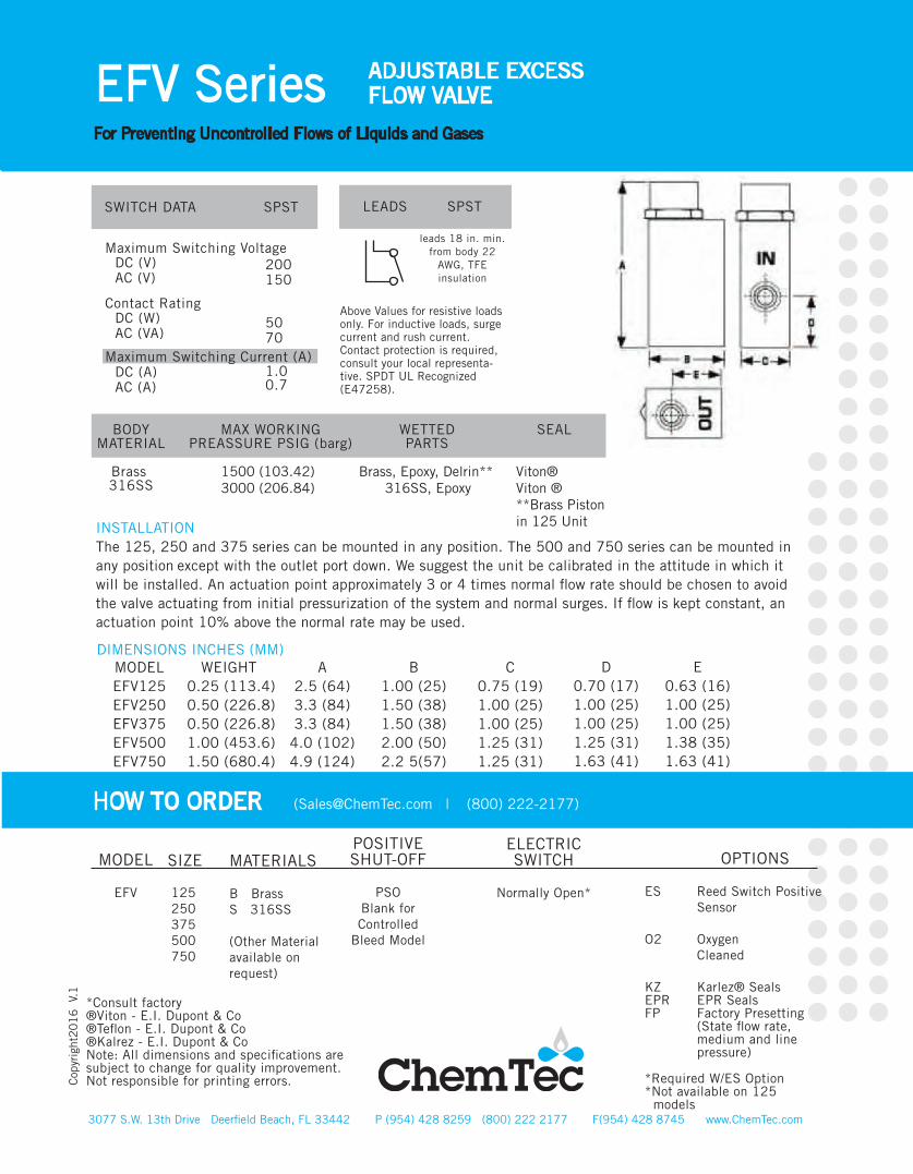
Brass 316SS
1500 (103.42) 3000 (206.84)
Brass, Epoxy, Delrin** 316SS, Epoxy
Viton®Viton ® **Brass Pistonin 125 UnitINSTALLATION
The 125, 250 and 375 series can be mounted in any position. The 500 and 750 series can be mounted in any position except with the outlet port down. We suggest the unit be calibrated in the attitude in which it will be installed. An actuation point approximately 3 or 4 times normal flow rate should be chosen to avoid the valve actuating from initial pressurization of the system and normal surges. If flow is kept constant, an actuation point 10% above the normal rate may be used.
DIMENSIONS INCHES (MM)MODELEFV125 EFV250 EFV375 EFV500 EFV750
WEIGHT0.25 (113.4) 0.50 (226.8) 0.50 (226.8) 1.00 (453.6) 1.50 (680.4)
A2.5 (64) 3.3 (84) 3.3 (84)
4.0 (102) 4.9 (124)
B1.00 (25) 1.50 (38) 1.50 (38) 2.00 (50) 2.2 5(57)
C0.75 (19) 1.00 (25) 1.00 (25) 1.25 (31) 1.25 (31)
D0.70 (17) 1.00 (25) 1.00 (25) 1.25 (31) 1.63 (41)
E0.63 (16) 1.00 (25) 1.00 (25) 1.38 (35) 1.63 (41)
HOW TO ORDER ([email protected] | (800) 222-2177)
MODEL
EFV
125 250 375 500 750
MATERIALS
B BrassS 316SS
(Other Material available on request)
POSITIVESHUT-OFF
PSOBlank for Controlled
Bleed Model
*Consult factory ®Viton - E.I. Dupont & Co®Teflon - E.I. Dupont & Co ®Kalrez - E.I. Dupont & CoNote: All dimensions and specifications are subject to change for quality improvement. Not responsible for printing errors.
SIZEELECTRICSWITCH
Normally Open*
OPTIONS
ES Reed Switch Positive Sensor
O2 Oxygen Cleaned
KZ Karlez® SealsEPR EPR SealsFP Factory Presetting (State flow rate, medium and line pressure)
*Required W/ES Option*Not available on 125 models
Minimum Maximum Minimum Maximum Minimum MaximumMinimum Maximum
MAO-125-AA
MAO-125-BB
MAO-250-AA
MAO-250-BB
3077 S.W. 13th Drive Deerfield Beach, FL 33442 P (954) 428 8259 (800) 222 2177 F(954) 428 8745 www.ChemTec.com
EFV MRS Series MANUAL RESETADJUSTABLE EXCESS FLOW VALVE
With Integral Manual Reset For Preventing Uncontrolled Flows of Gases and Liquids
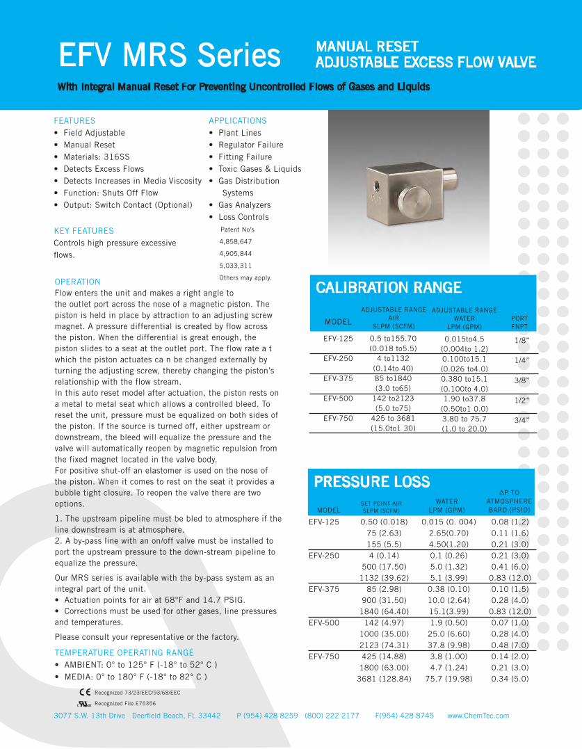
FEATURES• Field Adjustable• Manual Reset• Materials: 316SS• Detects Excess Flows• Detects Increases in Media Viscosity• Function: Shuts Off Flow• Output: Switch Contact (Optional)
APPLICATIONS• Plant Lines• Regulator Failure• Fitting Failure• Toxic Gases & Liquids• Gas Distribution Systems• Gas Analyzers • Loss Controls Patent No’s
4,858,647
4,905,844
5,033,311
Others may apply.
KEY FEATURESControls high pressure excessive flows.
TEMPERATURE OPERATING RANGE• AMBIENT: 0° to 125° F (-18° to 52° C )• MEDIA: 0° to 180° F (-18° to 82° C )
OPERATIONFlow enters the unit and makes a right angle tothe outlet port across the nose of a magnetic piston. The piston is held in place by attraction to an adjusting screw magnet. A pressure differential is created by flow across the piston. When the differential is great enough, the piston slides to a seat at the outlet port. The flow rate a t which the piston actuates ca n be changed externally by turning the adjusting screw, thereby changing the piston’s relationship with the flow stream.In this auto reset model after actuation, the piston rests on a metal to metal seat which allows a controlled bleed. To reset the unit, pressure must be equalized on both sides of the piston. If the source is turned off, either upstream or downstream, the bleed will equalize the pressure and the valve will automatically reopen by magnetic repulsion from the fixed magnet located in the valve body.For positive shut-off an elastomer is used on the nose of the piston. When it comes to rest on the seat it provides a bubble tight closure. To reopen the valve there are two options.
1. The upstream pipeline must be bled to atmosphere if the line downstream is at atmosphere.2. A by-pass line with an on/off valve must be installed to port the upstream pressure to the down-stream pipeline to equalize the pressure.
Our MRS series is available with the by-pass system as an integral part of the unit.• Actuation points for air at 68°F and 14.7 PSIG.• Corrections must be used for other gases, line pressures and temperatures.
Please consult your representative or the factory.
®
Recognized 73/23/EEC/93/68/EEC
Recognized File E75356
0.5 to155.70 (0.018 to5.5)
4 to1132 (0.14to 40) 85 to1840 (3.0 to65)
142 to2123 (5.0 to75)
425 to 3681 (15.0to1 30)
1/8”
1/4”
3/8”
1/2“
3/4”
ADJUSTABLE RANGEAIR
SLPM (SCFM)
PRESSURE LOSS
PORTFNPT
WATERLPM (GPM)
∆P TOATMOSPHEREBARD (PSID)MODEL
EFV-125
EFV-250
EFV-375
EFV-500
EFV-750
0.50 (0.018) 75 (2.63) 155 (5.5)4 (0.14)
500 (17.50) 1132 (39.62)
85 (2.98) 900 (31.50)
1840 (64.40) 142 (4.97)
1000 (35.00) 2123 (74.31) 425 (14.88)
1800 (63.00) 3681 (128.84)
EFV-125
EFV-250
EFV-375
EFV-500
EFV-750
0.015 (0. 004) 2.65(0.70) 4.50(1.20) 0.1 (0.26) 5.0 (1.32) 5.1 (3.99)
0.38 (0.10) 10.0 (2.64) 15.1(3.99) 1.9 (0.50)
25.0 (6.60) 37.8 (9.98) 3.8 (1.00) 4.7 (1.24)
75.7 (19.98)
0.08 (1.2) 0.11 (1.6) 0.21 (3.0) 0.21 (3.0) 0.41 (6.0)
0.83 (12.0) 0.10 (1.5) 0.28 (4.0)
0.83 (12.0) 0.07 (1.0) 0.28 (4.0) 0.48 (7.0) 0.14 (2.0) 0.21 (3.0) 0.34 (5.0)
ADJUSTABLE RANGEWATER
LPM (GPM)
0.015to4.5 (0.004to 1.2) 0.100to15.1 (0.026 to4.0)0.380 to15.1 (0.100to 4.0)1.90 to37.8
(0.50to1 0.0)3.80 to 75.7 (1.0 to 20.0)
CALIBRATION RANGE
MODEL
SET POINT AIRSLPM (SCFM)
3077 S.W. 13th Drive Deerfield Beach, FL 33442 P (954) 428 8259 (800) 222 2177 F(954) 428 8745 www.ChemTec.com
EFV MRS Series MANUAL RESETADJUSTABLE EXCESS FLOW VALVE
With Integral Manual Reset For Preventing Uncontrolled Flows of Gases and Liquids
Cop
yrig
ht2
01
6
V.1
Above Values for resistive loads only. For inductive loads, surge current and rush current. Contact protection is required, consult your local representa-tive. SPDT UL Recognized (E47258).
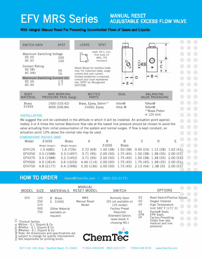
SPSTSWITCH DATA
Maximum Switching Voltage
Contact Rating
Maximum Switching Current (A)
DC (V)AC (V)
DC (W)AC (VA)
DC (A)AC (A)
200150
5070
1.00.7
BODYMATERIAL
MAX WORKINGPRESSURE PSIG (barg)
SEAL
LEADS SPST
leads 18 in. min. from body 22
AWG, TFE insulation
WETTEDPARTS
Brass 316SS
1500 (103.42) 3000 (206.84)
Brass, Epoxy, Delrin** 316SS, Epoxy
Viton®Viton ®
BALANCINGVALVE PACKAGING
Teflon®Teflon®**Brass Pistonin 125 UnitINSTALLATION
We suggest the unit be calibrated in the attitude in which it will be installed. An actuation point approxi-mately 3 or 4 times the normal Maximum flow rate at the lowest line pressure should be chosen to avoid the valve actuating from initial pressurization of the system and normal surges. If flow is kept constant, an actuation point 10% above the normal rate may be used.
DIMENSIONS INCHES (MM)Model
EFV125 EFV250 EFV375 EFV500 EFV750
316SSWeight (lbs/gm)
1.5 (680) 3.5 (1588) 3.5 (1588) 4.0 (1814) 4.8 (2177)
B316SS
1.50 (38) 2.00 (50) 2.00 (50) 2.00 (50) 2.00 (50)
BBrass
1.50 (38) 1.75 (45) 1.75 (45) 1.75 (45) 1.75 (45)
C
0.95 (24) 1.50 (38) 1.50 (38) 1.75 (45) 2.13 (54)
D
1.12 (28) 1.38 (35) 1.38 (35) 1.38 (35) 1.38 (35
E
1.62 (41) 2.00 (51) 2.00 (51) 2.00 (51) 2.00 (51)
A
2.72 (69) 3.71 (95) 3.71 (95)
4.46 (114) 5.35 (136)
BrassWeight (lbs/gm)
1.6 (726) 3.3 (1497) 3.2 (1452) 3.6 (1633) 4.4 (1996)
HOW TO ORDER ([email protected] | (800) 222-2177)
MODEL
EFV
125 250 375 500 750
MATERIALS
B BrassS 316SS
(Other Material available on request)
MANUALRESET MODEL
MRSManual Reset
Model
*Consult factory ®Viton - E.I. Dupont & Co®Teflon - E.I. Dupont & Co ®Kalrez - E.I. Dupont & CoNote: All dimensions and specifications are subject to change for quality improvement. Not responsible for printing errors.
SIZE SWITCH
Normally Open(ES not available on
125 model)Factory Preset
Required(Standard Option;
leave blank ifchoosing NO.)
OPTIONS
ES Reed Switch/Positive SensorO2 Oxygen CleanedHT High Temperature Unit 340˚ F (171˚ C)KZ Karlez® SealsEPR EPR SealsFP Factory Presetting (State flow rate, medium and line pressure)
Minimum Maximum Minimum Maximum
MAO-500-AA
MAO-500-BB
3077 S.W. 13th Drive Deerfield Beach, FL 33442 P (954) 428 8259 (800) 222 2177 F(954) 428 8745 www.ChemTec.com
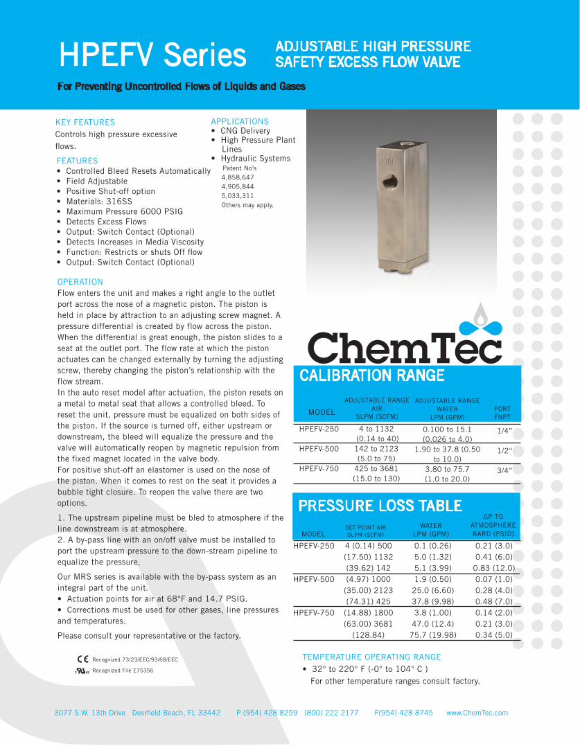
HPEFV Series ADJUSTABLE HIGH PRESSURESAFETY EXCESS FLOW VALVE
For Preventing Uncontrolled Flows of Liquids and Gases
FEATURES• Controlled Bleed Resets Automatically• Field Adjustable• Positive Shut-off option• Materials: 316SS• Maximum Pressure 6000 PSIG• Detects Excess Flows• Output: Switch Contact (Optional)• Detects Increases in Media Viscosity• Function: Restricts or shuts Off flow• Output: Switch Contact (Optional)
APPLICATIONS• CNG Delivery• High Pressure Plant Lines• Hydraulic Systems Patent No’s 4,858,647 4,905,844 5,033,311 Others may apply.
KEY FEATURESControls high pressure excessive flows.
OPERATIONFlow enters the unit and makes a right angle to the outlet port across the nose of a magnetic piston. The piston is held in place by attraction to an adjusting screw magnet. A pressure differential is created by flow across the piston. When the differential is great enough, the piston slides to a seat at the outlet port. The flow rate at which the piston actuates can be changed externally by turning the adjusting screw, thereby changing the piston’s relationship with the flow stream. In the auto reset model after actuation, the piston resets on a metal to metal seat that allows a controlled bleed. To reset the unit, pressure must be equalized on both sides of the piston. If the source is turned off, either upstream or downstream, the bleed will equalize the pressure and the valve will automatically reopen by magnetic repulsion from the fixed magnet located in the valve body. For positive shut-off an elastomer is used on the nose of the piston. When it comes to rest on the seat it provides a bubble tight closure. To reopen the valve there are two options.
1. The upstream pipeline must be bled to atmosphere if the line downstream is at atmosphere.2. A by-pass line with an on/off valve must be installed to port the upstream pressure to the down-stream pipeline to equalize the pressure.
Our MRS series is available with the by-pass system as an integral part of the unit.• Actuation points for air at 68°F and 14.7 PSIG.• Corrections must be used for other gases, line pressures and temperatures.
Please consult your representative or the factory.
®
Recognized 73/23/EEC/93/68/EEC
Recognized File E75356
TEMPERATURE OPERATING RANGE• 32° to 220° F (-0° to 104° C ) For other temperature ranges consult factory.
4 to 1132 (0.14 to 40) 142 to 2123 (5.0 to 75)
425 to 3681 (15.0 to 130)
1/4”
1/2“
3/4”
ADJUSTABLE RANGEAIR
SLPM (SCFM)
PRESSURE LOSS TABLE
PORTFNPT
WATERLPM (GPM)
∆P TOATMOSPHEREBARD (PSID)MODEL
HPEFV-250
HPEFV-500
HPEFV-750
4 (0.14) 500 (17.50) 1132 (39.62) 142 (4.97) 1000
(35.00) 2123 (74.31) 425
(14.88) 1800 (63.00) 3681
(128.84)
HPEFV-250
HPEFV-500
HPEFV-750
0.1 (0.26) 5.0 (1.32) 5.1 (3.99) 1.9 (0.50)
25.0 (6.60) 37.8 (9.98) 3.8 (1.00)
47.0 (12.4) 75.7 (19.98)
0.21 (3.0)0.41 (6.0)
0.83 (12.0) 0.07 (1.0) 0.28 (4.0) 0.48 (7.0) 0.14 (2.0) 0.21 (3.0) 0.34 (5.0)
ADJUSTABLE RANGEWATER
LPM (GPM)
0.100 to 15.1 (0.026 to 4.0)
1.90 to 37.8 (0.50 to 10.0)
3.80 to 75.7 (1.0 to 20.0)
CALIBRATION RANGE
MODEL
SET POINT AIRSLPM (SCFM)

3077 S.W. 13th Drive Deerfield Beach, FL 33442 P (954) 428 8259 (800) 222 2177 F(954) 428 8745 www.ChemTec.com
HPEFV Series ADJUSTABLE HIGH PRESSURESAFETY EXCESS FLOW VALVE
For Preventing Uncontrolled Flows of Liquids and Gases
Cop
yrig
ht2
01
6
V.1
Above Values for resistive loads only. For inductive loads, surge current and rush current. Contact protection is required, consult your local representative. SPDT UL Recognized (E47258).
SPSTSWITCH DATA
Maximum Switching Voltage
Contact Rating
Maximum Switching Current (A)
DC (V)AC (V)
DC (W)AC (VA)
DC (A)AC (A)
200150
5070
1.00.7
BODYMATERIAL
MAX WORKINGPRESSURE PSIG (barg)
SEALLEADS SPST
leads 18 in. min. from body 22
AWG, TFE insulation
WETTEDPARTS
Brass 316SS
1500 (103.42) 3000 (206.84)
Brass, Epoxy, Delrin** 316SS, Epoxy
Viton®Viton ®
INSTALLATIONWe suggest the unit be calibrated in the attitude in which it will be installed. An actuation point approximately 3 or 4 times the normal Maxi-mum flow rate at the lowest line pressure should be chosen to avoid the valve actuating from initial pressurization of the system and normal surges. If flow is kept constant, an actuation point 10% above the normal rate may be used. DIMENSIONS INCHES (MM)
ModelHPEFV-250 HPEFV-500 HPEFV-750
B1.50 (38) 2.00 (50) 2.25 (57))
C1.00 (25) 1.25 (32) 1.25 (32)
D1.00 (25)1.25 (32)
1.625 (45)
E1.00 (25)1.37 (35)
1.625 (41)
A3.75 (149) 4.25 (108) 5.25 (133)
Weight1.47 (0.667)
2.625 (1.190) 3.44 (1.560)
SPECIFICATIONS
HOW TO ORDER ([email protected] | (800) 222-2177)
MODEL
HPEFV
200 500 750
MATERIALS
S 316SS
(Other Material available on request)
POSITIVESHUT-OFF
PSOBlank forcontrolled
bleedmodel
Controled Bleed Model*
*Standard
*Consult factory ®Viton - E.I. Dupont & Co®Teflon - E.I. Dupont & Co ®Kalrez - E.I. Dupont & CoNote: All dimensions and specifications are subject to change for quality improvement. Not responsible for printing errors.
SIZE SWITCH
ESFP* Normally Open*
FP required*Standard
Electrical Switch, Requires Factory
Presetting
OPTIONS
O2 Oxygen CleanedHT High Temperature Unit 340˚ F (171˚ C)KZ Karlez® SealsEPR EPR SealsFP Factory Presetting (State flow rate, medium and line pressure)HE Helium Leak Testing

FLOW
MO
NITO
RS

FLOW
ME
TER
S

EXC
ES
S FLO
W VA
LVES
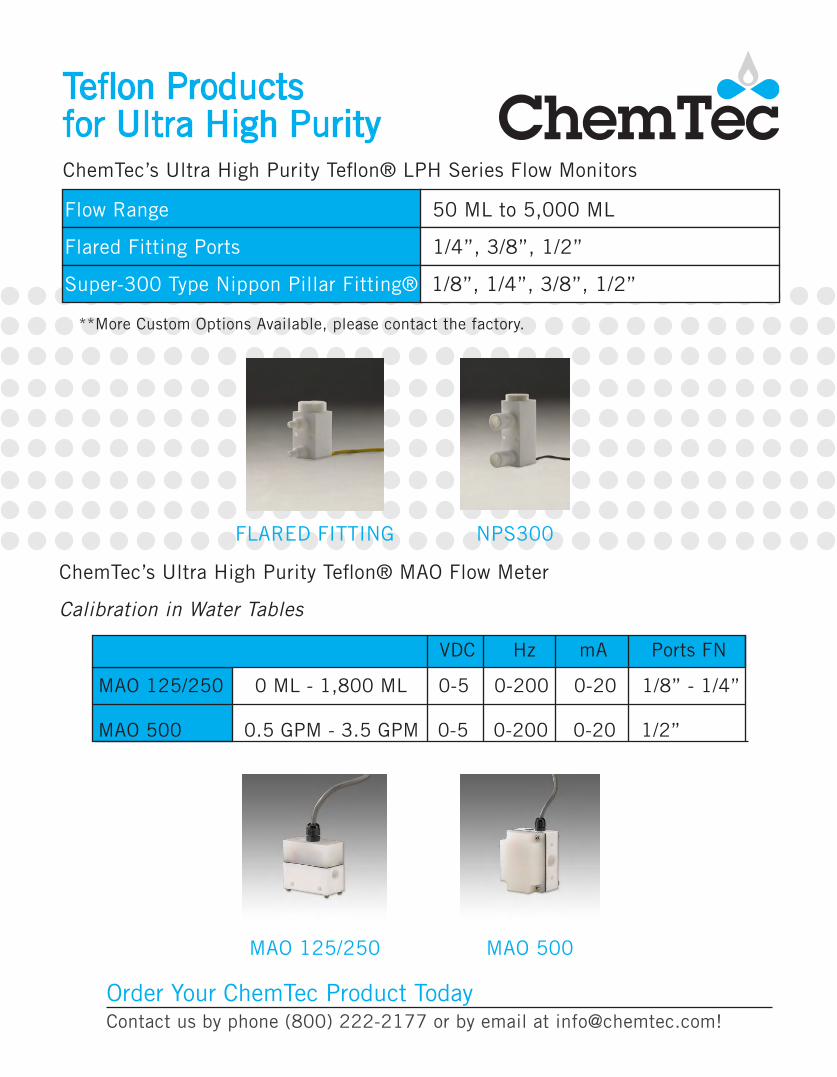
Teflon Productsfor Ultra High Purity
Flow Range 50 ML to 5,000 ML
Flared Fitting Ports 1/4”, 3/8”, 1/2”
Super-300 Type Nippon Pillar Fitting® 1/8”, 1/4”, 3/8”, 1/2”
**More Custom Options Available, please contact the factory.
FLARED FITTING NPS300
ChemTec’s Ultra High Purity Teflon® LPH Series Flow Monitors
ChemTec’s Ultra High Purity Teflon® MAO Flow Meter
Calibration in Water Tables
MAO 125/250 0 ML - 1,800 ML 0-5 0-200 0-20 1/8” - 1/4”
MAO 500 0.5 GPM - 3.5 GPM 0-5 0-200 0-20 1/2”
VDC Hz mA Ports FN
MAO 125/250 MAO 500
Order Your ChemTec Product TodayContact us by phone (800) 222-2177 or by email at [email protected]!
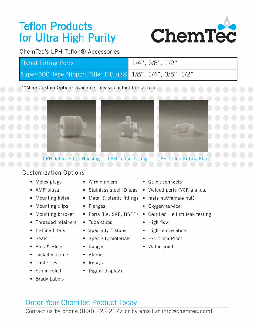
Teflon Productsfor Ultra High Purity
Flared Fitting Ports 1/4”, 3/8”, 1/2”
Super-300 Type Nippon Pillar Fitting® 1/8”, 1/4”, 3/8”, 1/2”
ChemTec’s LPH Teflon® Accessories
**More Custom Options Available, please contact the factory.
LPH Teflon Filter Housing LPH Teflon Fitting LPH Teflon Fitting Flare
Customization Options
• Molex plugs
• AMP plugs
• Mounting holes
• Mounting clips
• Mounting bracket
• Threaded retainers
• In-Line filters
• Seals
• Pins & Plugs
• Jacketed cable
• Cable ties
• Strain relief
• Brady Labels
• Wire markers
• Stainless steel ID tags
• Metal & plastic fittings
• Flanges
• Ports (i.e. SAE, BSPP)
• Tube stubs
• Specialty Pistons
• Specialty materials
• Gauges
• Alarms
• Relays
• Digital displays
• Quick connects
• Welded ports (VCR glands,
• male nut/female nut)
• Oxygen service
• Certified Helium leak testing
• High flow
• High temperature
• Explosion Proof
• Water proof
Order Your ChemTec Product TodayContact us by phone (800) 222-2177 or by email at [email protected]!
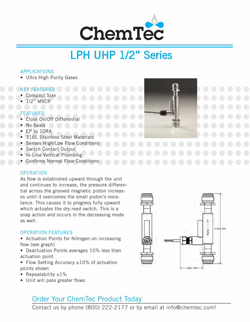
LPH UHP 1/2” SeriesAPPLICATIONS• Ultra High Purity Gases
KEY FEATURES• Compact Size• 1/2” MVCR
FEATURES• Close On/Off Differential• No Seals• EP to 10RA• 316L Stainless Steel Materials• Senses High/Low Flow Conditions• Switch Contact Output• In-Line Vertical Plumbing• Confirms Normal Flow Conditions
OPERATION As flow is established upward through the unit and continues to increase, the pressure differen-tial across the grooved magnetic piston increas-es until it overcomes the small piston’s resis-tance. This causes it to progress fully upward which actuates the dry reed switch. This is a snap action and occurs in the decreasing mode as well.
OPERATION FEATURES• Actuation Points for Nitrogen on increasing flow (see graph)• Deactuation Points averages 10% less than actuation point • Flow Setting Accuracy ±10% of actuation points shown• Repeatability ±1%• Unit will pass greater flows
Order Your ChemTec Product TodayContact us by phone (800) 222-2177 or by email at [email protected]!
Flow Monitors,Flow Meters,
Excess Flow Valves
3077 S.W. 13th Drive Deerfield Beach, FL 33442 P (954) 428 8259 (800) 222 2177 [email protected] www.ChemTec.com
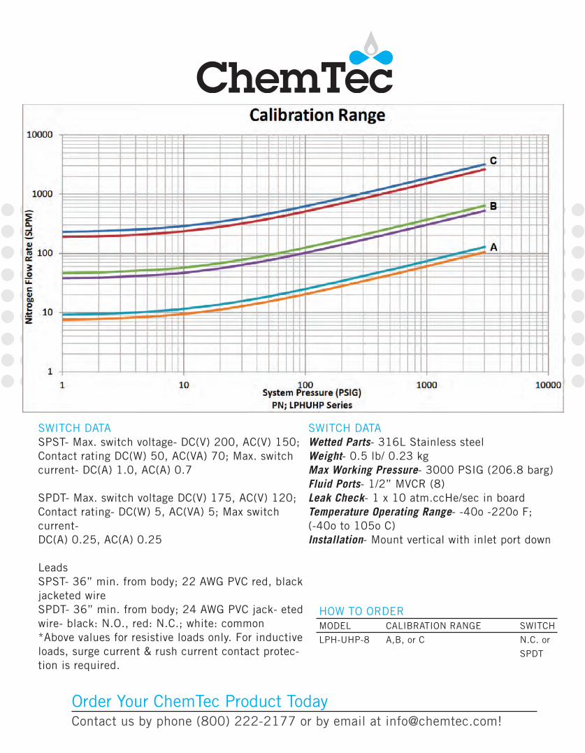
SWITCH DATA SPST- Max. switch voltage- DC(V) 200, AC(V) 150; Contact rating DC(W) 50, AC(VA) 70; Max. switch current- DC(A) 1.0, AC(A) 0.7
SPDT- Max. switch voltage DC(V) 175, AC(V) 120; Contact rating- DC(W) 5, AC(VA) 5; Max switch current-DC(A) 0.25, AC(A) 0.25
LeadsSPST- 36” min. from body; 22 AWG PVC red, black jacketed wireSPDT- 36” min. from body; 24 AWG PVC jack- eted wire- black: N.O., red: N.C.; white: common*Above values for resistive loads only. For inductive loads, surge current & rush current contact protec-tion is required.
SWITCH DATA Wetted Parts- 316L Stainless steel Weight- 0.5 lb/ 0.23 kgMax Working Pressure- 3000 PSIG (206.8 barg)Fluid Ports- 1/2” MVCR (8)Leak Check- 1 x 10 atm.ccHe/sec in boardTemperature Operating Range- -40o -220o F; (-40o to 105o C)Installation- Mount vertical with inlet port down
HOW TO ORDER MODEL CALIBRATION RANGE SWITCH
LPH-UHP-8 A,B, or C N.C. or
SPDT
Order Your ChemTec Product TodayContact us by phone (800) 222-2177 or by email at [email protected]!


