www.walworthvalves.com
CATALOGFLOATING BALL VALVE

www.walworthvalves.com 3
INDEXINTRODUCTION
WALWORTH ENGINEERING CONTROL ..................................................................................................................... 5WALWORTH QUALITY SYSTEM .................................................................................................................................. 5QUALITY CONTROL EQUIPMENT ............................................................................................................................... 9
FLOATING BALL VALVES
INTRODUCTION OF FLOATING BALL VALVES ........................................................................................................11STRUCTURAL FEATURES ......................................................................................................................................... 12 FLOATING BALL CLASS 600 WOG ........................................................................................................................... 14FLOATING BALL CLASS 1000 WOG & 2000 WOG .................................................................................................. 17 STANDARD FLOATING BALL CLASS 150, 300 & 600 ............................................................................................. 21 FIRE SAFE FLOATING BALL VALVES 150, 300 & 600 ............................................................................................. 26 FIRE SAFE FLOATING BALL VALVES 1500 ........................................................................................................... ..34FIRE SAFE FLOATING BALL VALVES 800, 1500 & 2500 (THD OR SW ENDS) ...................................................... 37 ACCESSORIES FOR OPERATION ............................................................................................................................. 42PRESSURE-TEMPERATURE RATINGS .................................................................................................................... 42TORQUES AND CV FLOW RATES ............................................................................................................................. 45 BODY AND TRIM MATERIALS ................................................................................................................................... 45 FLOATING BALL VALVE FIGURES ........................................................................................................................... 46HOW TO ORDER ......................................................................................................................................................... 47 DESIGN BASIS ............................................................................................................................................................ 48 TERMS AND CONDITIONS ......................................................................................................................................... 50
www.walworthvalves.com4
WALWORTH
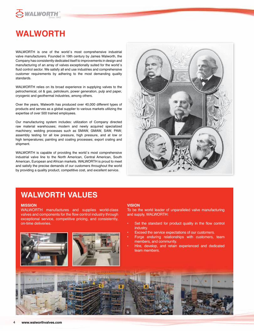
WALWORTH is one of the world´s most comprehensive industrial valve manufacturers. Founded in 19th century by James Walworth, the Company has consistently dedicated itself to improvements in design and manufacturing of an array of valves exceptionally suited for the world´s fluid control sector. We satisfy all end use industries and comprehensive customer requirements by adhering to the most demanding quality standards.
WALWORTH relies on its broad experience in supplying valves to the petrochemical, oil & gas, petroleum, power generation, pulp and paper, cryogenic and geothermal industries, among others.
Over the years, Walworth has produced over 40,000 different types of products and serves as a global supplier to various markets utilizing the expertise of over 500 trained employees.
Our manufacturing system includes: utilization of Company directed raw material warehouses; modern and newly acquired specialized machinery; welding processes such as SMAW, GMAW, SAW, PAW; assembly testing for all low pressure, high pressure, and at low or high temperatures; painting and coating processes; export crating and shipment.
WALWORTH is capable of providing the world´s most comprehensive industrial valve line to the North American, Central American, South American, European and African markets. WALWORTH is proud to meet and satisfy the precise demands of our customers throughout the world by providing a quality product, competitive cost, and excellent service.
WALWORTH VALUESMISSIONWALWORTH manufactures and supplies world-class valves and components for the flow control industry through exceptional service, competitive pricing, and consistently, on-time deliveries.
VISIONTo be the world leader of unparalleled valve manufacturing and supply, WALWORTH:
• Set the standard for product quality in the flow control industry.
• Exceed the service expectations of our customers.• Forge enduring relationships with customers, team
members, and community.• Hire, develop, and retain experienced and dedicated
team members.
www.walworthvalves.com 5
WALWORTH products are manufactured following strictly the most recognized international standards all over the world, such as API, ANSI, ASME, ASTM, MSS, NACE, AWWA, BSI, CSA, among others. Our Engineering team is always studying the new updates of these standards to incorporate any changes that may affect the design, regulations or performance of our products, being leaders in the new developments achieved.
Design is made using the most advanced technology and equip-ment, using finite elements and CAD system programs to ensure the proper assembly and performance of products since the concept, calculation and detailed drawings for manufacturing. WALWORTH is a leader in the development of new products according to valve market current needs.
Throughout the years, WALWORTH has developed its Quality System which is an integral part of our manufacturing policy. Our primary goal is to provide products that meet and exceed market standards. In this sense, WALWORTH is an ISO-9001 Audited and Certified Company that has achieved major certifications worldwide. Our system consists of a rigorous quality control as well as the selection of raw materials from approved vendors. Control over our manufacturing process is vital. Serial numbers allow WALWORTH to monitor and trace fabrication processes along with the materials of components.
WALWORTH ENGINEERING CONTROL
WALWORTH QUALITY SYSTEM
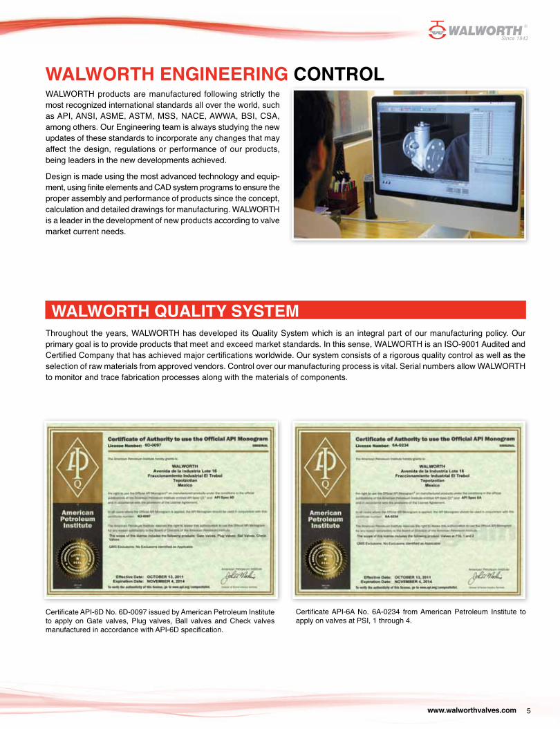
Certificate API-6D No. 6D-0097 issued by American Petroleum Institute to apply on Gate valves, Plug valves, Ball valves and Check valves manufactured in accordance with API-6D specification.
Certificate API-6A No. 6A-0234 from American Petroleum Institute to apply on valves at PSI, 1 through 4.
www.walworthvalves.com6
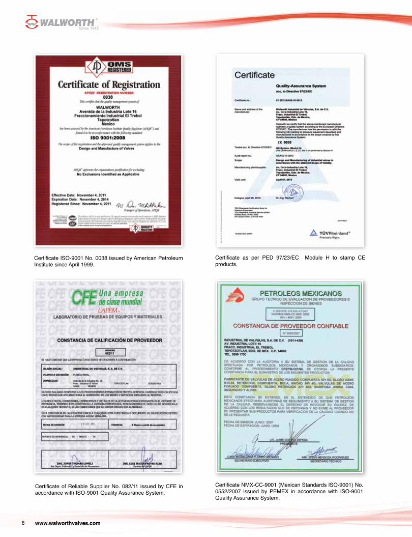
Certificate ISO-9001 No. 0038 issued by American Petroleum Institute since April 1999.
Certificate NMX-CC-9001 (Mexican Standards ISO-9001) No. 0552/2007 issued by PEMEX in accordance with ISO-9001 Quality Assurance System.
Certificate of Reliable Supplier No. 082/11 issued by CFE in accordance with ISO-9001 Quality Assurance System.
Certificate as per PED 97/23/EC Module H to stamp CE products.
www.walworthvalves.com 7
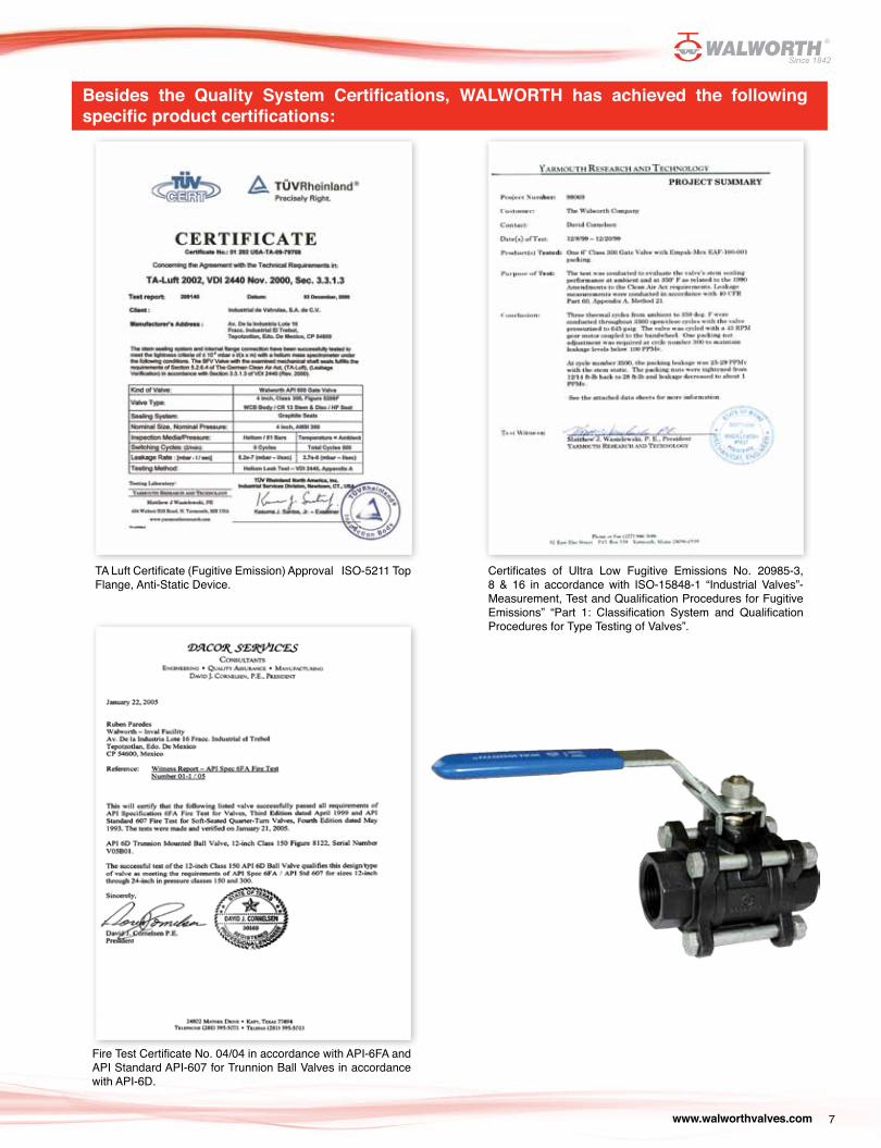
Besides the Quality System Certifications, WALWORTH has achieved the following specific product certifications:
Certificates of Ultra Low Fugitive Emissions No. 20985-3, 8 & 16 in accordance with ISO-15848-1 “Industrial Valves”-Measurement, Test and Qualification Procedures for Fugitive Emissions” “Part 1: Classification System and Qualification Procedures for Type Testing of Valves”.
Fire Test Certificate No. 04/04 in accordance with API-6FA and API Standard API-607 for Trunnion Ball Valves in accordance with API-6D.
TA Luft Certificate (Fugitive Emission) Approval ISO-5211 Top Flange, Anti-Static Device.
www.walworthvalves.com8
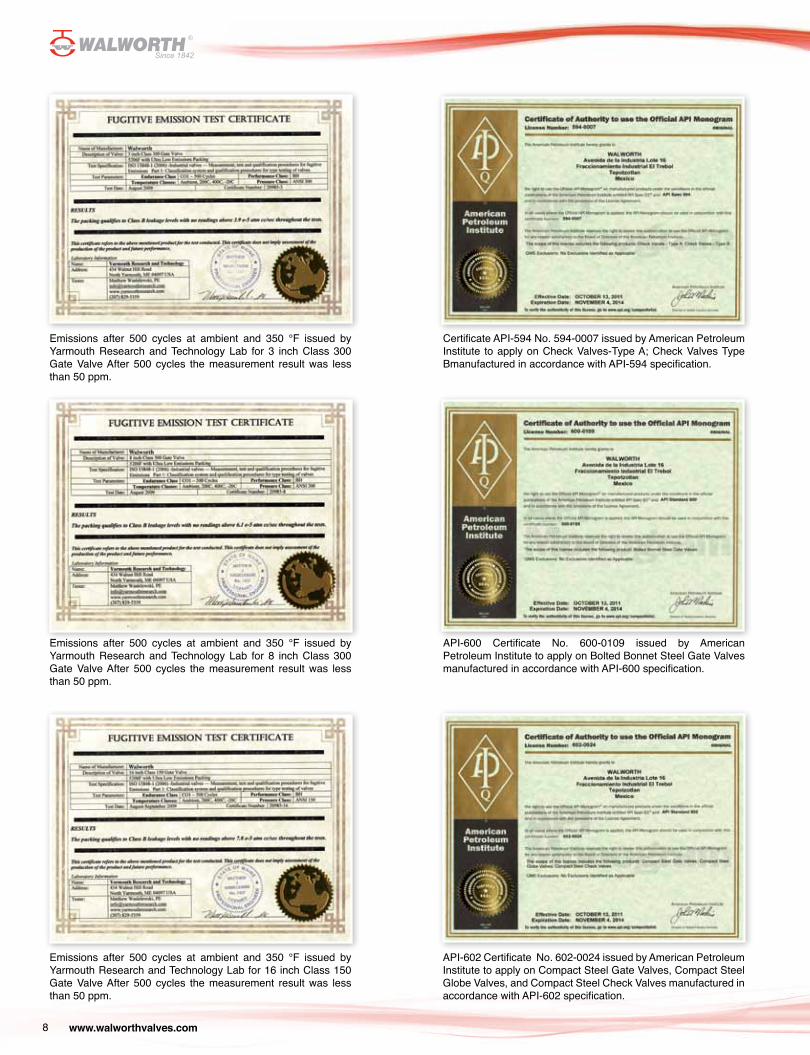
Emissions after 500 cycles at ambient and 350 °F issued by Yarmouth Research and Technology Lab for 3 inch Class 300 Gate Valve After 500 cycles the measurement result was less than 50 ppm.
Certificate API-594 No. 594-0007 issued by American Petroleum Institute to apply on Check Valves-Type A; Check Valves Type Bmanufactured in accordance with API-594 specification.
API-600 Certificate No. 600-0109 issued by American Petroleum Institute to apply on Bolted Bonnet Steel Gate Valves manufactured in accordance with API-600 specification.
Emissions after 500 cycles at ambient and 350 °F issued by Yarmouth Research and Technology Lab for 8 inch Class 300 Gate Valve After 500 cycles the measurement result was less than 50 ppm.
Emissions after 500 cycles at ambient and 350 °F issued by Yarmouth Research and Technology Lab for 16 inch Class 150 Gate Valve After 500 cycles the measurement result was less than 50 ppm.
API-602 Certificate No. 602-0024 issued by American Petroleum Institute to apply on Compact Steel Gate Valves, Compact Steel Globe Valves, and Compact Steel Check Valves manufactured in accordance with API-602 specification.
www.walworthvalves.com 9
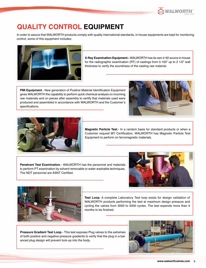
QUALITY CONTROL EQUIPMENT In order to assure that WALWORTH products comply with quality international standards, in-house equipments are kept for monitoring control, some of this equipment includes:
X-Ray Examination Equipment.- WALWORTH has its own Ir-92 source in-house for the radiographic examination (RT) of castings from 0.100” up to 2 1/2” wall thickness to verify the soundness of the casting raw material.
Magnetic Particle Test.- In a random basis for standard products or when a Customer request MT Certification, WALWORTH has Magnetic Particle Test Equipment to perform on ferromagnetic materials.
Test Loop. A complete Laboratory Test loop exists for design validation of WALWORTH products performing the test at maximum design pressure and cycling the valves from 3000 to 5000 cycles. The test expends more than 4 months to be finished.
PMI Equipment.- New generation of Positive Material Identification Equipment gives WALWORTH the capability to perform quick chemical analysis on incoming raw materials and on pieces after assembly to certify that materials used were produced and assembled in accordance with WALWORTH and the Customer’s specifications.
Penetrant Test Examination.- WALWORTH has the personnel and materials to perform PT examination by solvent removable or water washable techniques. The NDT personnel are ASNT Certified.
Pressure Gradient Test Loop.- This test exposes Plug valves to the extremes of both positive and negative pressure gradients to verify that the plug in a bal-anced plug design will prevent lock-up into the body.
www.walworthvalves.com10
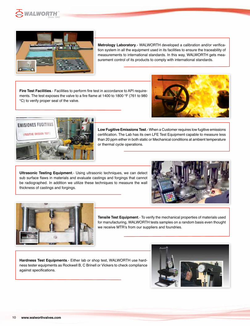
Metrology Laboratory.- WALWORTH developed a calibration and/or verifica-tion system in all the equipment used in its facilities to ensure the traceability of measurements to international standards. In this way, WALWORTH gets mea-surement control of its products to comply with international standards.
Low Fugitive Emissions Test.- When a Customer requires low fugitive emissions certification. The Lab has its own LFE Test Equipment capable to measure less than 20 ppm either in both static or Mechanical conditions at ambient temperature or thermal cycle operations.
Tensile Test Equipment.- To verify the mechanical properties of materials used for manufacturing, WALWORTH tests samples on a random basis even thought we receive MTR’s from our suppliers and foundries.
Fire Test Facilities.- Facilities to perform fire test in accordance to API require-ments. The test exposes the valve to a fire flame at 1400 to 1800 °F (761 to 980 °C) to verify proper seal of the valve.
Ultrasonic Testing Equipment.- Using ultrasonic techniques, we can detect sub surface flaws in materials and evaluate castings and forgings that cannot be radiographed. In addition we utilize these techniques to measure the wall thickness of castings and forgings.
Hardness Test Equipments.- Either lab or shop test, WALWORTH use hard-ness tester equipments as Rockwell B, C Brinell or Vickers to check compliance against specifications.
www.walworthvalves.com 11
PRODUCT RANGEType Firesafe or Not Firesafe design Size Pressure Class Ends Figure Nr
Two-Piece Floating Ball Valve Not Firesafe 1/4” to 2” 600 WOG Threaded 7711Three-Piece Floating Ball Valve Not Firesafe 1/4” to 4” 1000 & 2000 WOG Threaded or Socket Weld 7011, 7017, 7411, 7417Two-Piece Floating Ball Valve Not Firesafe 1/4” to 8” 150 & 300# Flanged 7112, 7312Two-Piece Floating Ball Valve Not Firesafe 1/2” to 4” 600# Flanged 7612Two-Piece Floating Ball Valve Firesafe 1/4” to 8” 150 & 300# Flanged 7112 Z, 7312 ZTwo-Piece Floating Ball Valve Firesafe 1/2” to 4” 600# Flanged 7612 Z
Three-Piece Floating Ball Valve Firesafe 1/4” to 2” 1500# Flanged 7512 ZThree-Piece Floating Ball Valve Firesafe 1/4” to 2” 800, 1500 & 2500# Threaded or Socket Weld 7811, 7817, 7511, 7517, 7211, 7217
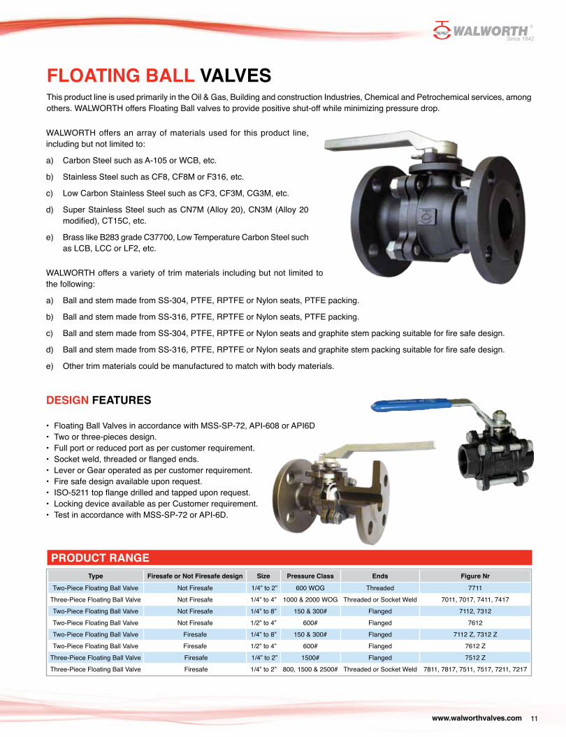
FLOATING BALL VALVESThis product line is used primarily in the Oil & Gas, Building and construction Industries, Chemical and Petrochemical services, among others. WALWORTH offers Floating Ball valves to provide positive shut-off while minimizing pressure drop.
WALWORTH offers an array of materials used for this product line, including but not limited to:
a) Carbon Steel such as A-105 or WCB, etc.
b) Stainless Steel such as CF8, CF8M or F316, etc.
c) Low Carbon Stainless Steel such as CF3, CF3M, CG3M, etc.
d) Super Stainless Steel such as CN7M (Alloy 20), CN3M (Alloy 20 modified), CT15C, etc.
e) Brass like B283 grade C37700, Low Temperature Carbon Steel such as LCB, LCC or LF2, etc.
WALWORTH offers a variety of trim materials including but not limited to the following:
a) Ball and stem made from SS-304, PTFE, RPTFE or Nylon seats, PTFE packing.
b) Ball and stem made from SS-316, PTFE, RPTFE or Nylon seats, PTFE packing.
c) Ball and stem made from SS-304, PTFE, RPTFE or Nylon seats and graphite stem packing suitable for fire safe design.
d) Ball and stem made from SS-316, PTFE, RPTFE or Nylon seats and graphite stem packing suitable for fire safe design.
e) Other trim materials could be manufactured to match with body materials.
DESIGN FEATURES
• Floating Ball Valves in accordance with MSS-SP-72, API-608 or API6D• Two or three-pieces design.• Full port or reduced port as per customer requirement.• Socket weld, threaded or flanged ends.• Lever or Gear operated as per customer requirement.• Fire safe design available upon request.• ISO-5211 top flange drilled and tapped upon request.• Locking device available as per Customer requirement.• Test in accordance with MSS-SP-72 or API-6D.
www.walworthvalves.com12
STRUCTURAL FEATURES
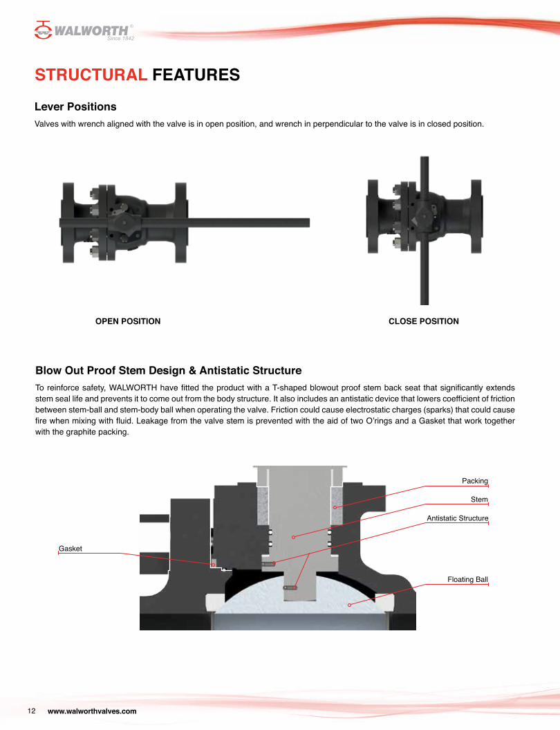
Lever PositionsValves with wrench aligned with the valve is in open position, and wrench in perpendicular to the valve is in closed position.
Blow Out Proof Stem Design & Antistatic StructureTo reinforce safety, WALWORTH have fitted the product with a T-shaped blowout proof stem back seat that significantly extends stem seal life and prevents it to come out from the body structure. It also includes an antistatic device that lowers coefficient of friction between stem-ball and stem-body ball when operating the valve. Friction could cause electrostatic charges (sparks) that could cause fire when mixing with fluid. Leakage from the valve stem is prevented with the aid of two O’rings and a Gasket that work together with the graphite packing.
OPEN POSITION CLOSE POSITION
Stem
Antistatic Structure
Floating Ball
Gasket
Packing
www.walworthvalves.com 13
STRUCTURAL FEATURES
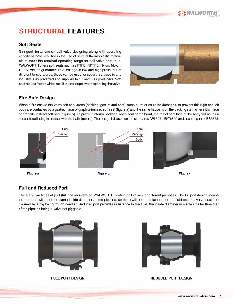
Soft SeatsStringent limitations on ball valve designing along with operating conditions have resulted in the use of several thermoplastic materi-als to meet the required operating range for ball valve seat thus, WALWORTH offers soft seats such as PTFE, RPTFE, Nylon, Molon, PEEK, etc., to guarantee zero leakage in low and high pressures at different temperatures, these can be used for several services in any industry, also preferred and supplied to Oil and Gas producers. Soft seat reduce friction which result in less torque when operating the valve.
Fire Safe DesignWhen a fire occurs the valve soft seal areas (packing, gasket and seat) came burnt or could be damaged, to prevent this right and left body are contacted by a gasket made of graphite instead soft seal (figure a) and the same happens on the packing stem where it is made of graphite instead soft seal (figure b). To prevent internal leakage when seat came burnt, the metal seal face of the body will act as a second seal being in contact with the ball (figure c). The design is based on the standards API 607, JB/T6899 and second part of BS6755.
Full and Reduced PortThere are two types of port (full and reduced) on WALWORTH floating ball valves for different purposes. The full port design means that the port will be of the same inside diameter as the pipeline, so there will be no resistance for the fluid and this valve could be cleaned by a pig being trough conduit. Reduced port provides resistance to the fluid, the inside diameter is a size smaller than that of the pipeline being a valve not piggable
FULL PORT DESIGN REDUCED PORT DESIGN
StemPacking
Body
EndGasket
Figure a Figure b Figure c
www.walworthvalves.com14
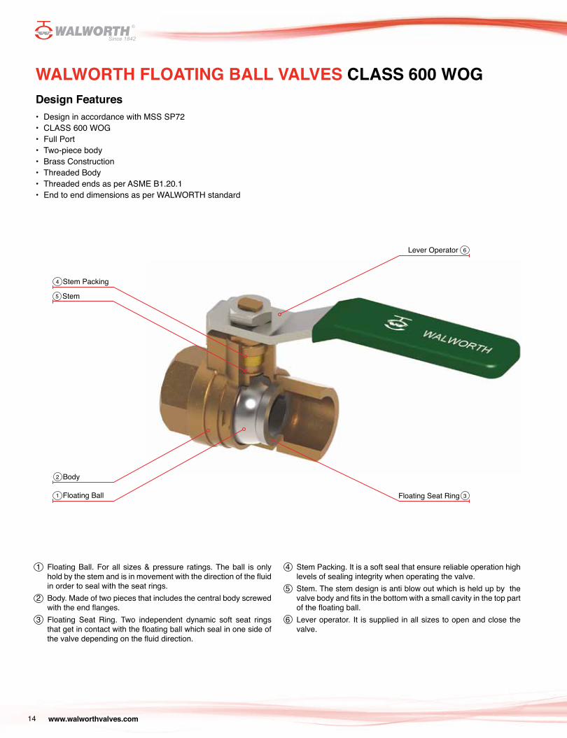
WALWORTH FLOATING BALL VALVES CLASS 600 WOGDesign Features• Design in accordance with MSS SP72• CLASS 600 WOG• Full Port• Two-piece body• Brass Construction• Threaded Body• Threaded ends as per ASME B1.20.1• End to end dimensions as per WALWORTH standard
Lever Operator
Floating Seat Ring
Stem Packing
Body
Stem
Floating Ball
1 Floating Ball. For all sizes & pressure ratings. The ball is only hold by the stem and is in movement with the direction of the fluid in order to seal with the seat rings.
2 Body. Made of two pieces that includes the central body screwed with the end flanges.
3 Floating Seat Ring. Two independent dynamic soft seat rings that get in contact with the floating ball which seal in one side of the valve depending on the fluid direction.
4 Stem Packing. It is a soft seal that ensure reliable operation high levels of sealing integrity when operating the valve.
5 Stem. The stem design is anti blow out which is held up by the valve body and fits in the bottom with a small cavity in the top part of the floating ball.
6 Lever operator. It is supplied in all sizes to open and close the valve.
4
5
2
1
6
3
www.walworthvalves.com 15
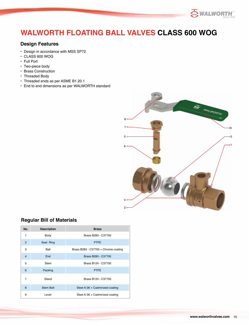
Design Features• Design in accordance with MSS SP72• CLASS 600 WOG• Full Port• Two-piece body• Brass Construction• Threaded Body• Threaded ends as per ASME B1.20.1• End to end dimensions as per WALWORTH standard
Regular Bill of MaterialsNo. Description Brass
1 Body Brass B283 - C37700
2 Seat Ring PTFE
3 Ball Brass B283 - C37700 + Chrome coating
4 End Brass B283 - C37700
5 Stem Brass B124 - C37700
6 Packing PTFE
7 Gland Brass B124 - C37700
8 Stem Bolt Steel A-36 + Cadminized coating
9 Lever Steel A-36 + Cadminized coating
WALWORTH FLOATING BALL VALVES CLASS 600 WOG
8
4
7
2
6
5
9
1
3
www.walworthvalves.com16
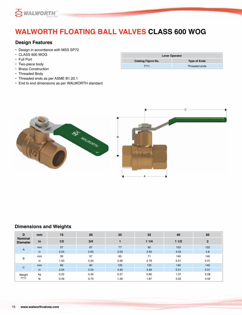
WALWORTH FLOATING BALL VALVES CLASS 600 WOGDesign Features• Design in accordance with MSS SP72• CLASS 600 WOG• Full Port• Two-piece body• Brass Construction• Threaded Body• Threaded ends as per ASME B1.20.1• End to end dimensions as per WALWORTH standard
Lever Operator
Catalog Figure No. Type of Ends
7711 Threaded ends
Dimensions and WeightsD
Nominal Diameter
mm 15 20 25 32 40 50
in 1/2 3/4 1 1 1/4 1 1/2 2
Amm 57 67 77 92 103 122in 2.24 2.64 3.03 3.62 4.05 4.8
Bmm 39 57 65 71 140 140in 1.53 2.24 2.56 2.79 5.51 5.51
Cmm 90 90 125 125 140 140in 3.54 3.54 4.92 4.92 5.51 5.51
Weight7711
kg 0.22 0.34 0.57 0.85 1.37 2.08lb 0.49 0.75 1.26 1.87 3.02 4.59
C
B
A
www.walworthvalves.com 17
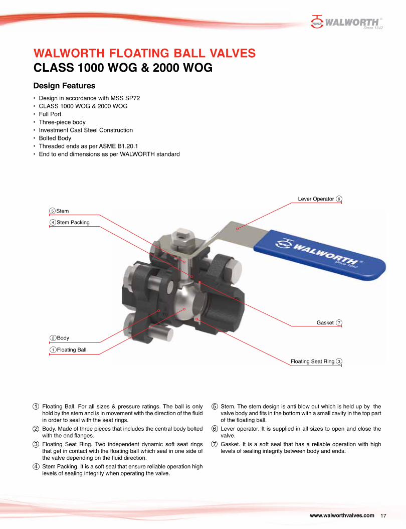
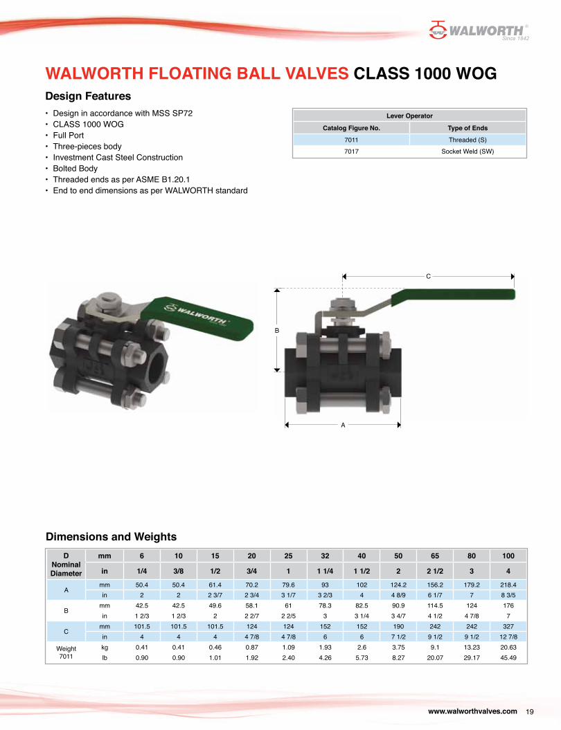
WALWORTH FLOATING BALL VALVES CLASS 1000 WOG & 2000 WOGDesign Features• Design in accordance with MSS SP72• CLASS 1000 WOG & 2000 WOG• Full Port• Three-piece body• Investment Cast Steel Construction• Bolted Body• Threaded ends as per ASME B1.20.1• End to end dimensions as per WALWORTH standard
Body
Stem
Stem Packing
Floating Ball
Floating Seat Ring
Gasket
Lever Operator
1 Floating Ball. For all sizes & pressure ratings. The ball is only hold by the stem and is in movement with the direction of the fluid in order to seal with the seat rings.
2 Body. Made of three pieces that includes the central body bolted with the end flanges.
3 Floating Seat Ring. Two independent dynamic soft seat rings that get in contact with the floating ball which seal in one side of the valve depending on the fluid direction.
4 Stem Packing. It is a soft seal that ensure reliable operation high levels of sealing integrity when operating the valve.
5 Stem. The stem design is anti blow out which is held up by the valve body and fits in the bottom with a small cavity in the top part of the floating ball.
6 Lever operator. It is supplied in all sizes to open and close the valve.
7 Gasket. It is a soft seal that has a reliable operation with high levels of sealing integrity between body and ends.
5
4
1
2
6
3
7

www.walworthvalves.com18
Design Features• Design in accordance with MSS SP72• CLASS 1000 WOG & 2000 WOG• Full Port• Three-piece body• Investment Cast Steel Construction• Bolted Body• Threaded ends as per ASME B1.20.1• End to end dimensions as per WALWORTH standard
Regular Bill of MaterialsNo. Description Carbon Steel with Trim F4
(SS304) Stainless Steel 316 Carbon Steel Trim F4 (SS304) NACE
Stainless Steel 316 with Trim F3 (SS316) NACE
1 Body ASTM A216 GR WCB ASTM A351 GR CF8M ASTM A216 GR WCB ASTM A351 GR CF8M
2 Seat Ring PTFE + Graphite
3 Ball SS304 SS316 SS304 SS316
4 Stud ASTM A193 Gr. B7 ASTM A193 Gr. B8 ASTM A193 Gr. B7M ASTM A193 Gr. B8M
5 Gasket PTFE
6 Nut ASTM A194 Gr. 2H ASTM A194 Gr. 8 ASTM A194 Gr. 2HM ASTM A194 Gr. 8M
7 End ASTM A216 GR WCB ASTM A351 GR CF8M ASTM A216 GR WCB ASTM A351 GR CF8M
8 Stem ASTM A182 Gr. F304 ASTM A182 Gr. F316 ASTM A182 Gr. F304 ASTM A182 Gr. F316
*9 Stem Seat PTFE
10 Packing PTFE
11 Packing Gland ASTM A216 GR WCB OR SS304 SS304 ASTM A216 GR WCB OR
SS304 SS304
12 Stem Nut ASTM A194 Gr. 2H ASTM A194 Gr. 8 ASTM A194 Gr. 2HM ASTM A194 Gr. 8M
13 Lever ASTM A216 GR WCB
*14 Identification Plate Stainless Steel Stainless Steel Stainless Steel Stainless Steel
* Not Shown
WALWORTH FLOATING BALL VALVES CLASS 1000 WOG & 2000 WOG
1110
8
6
5
1
2
1213
73
4
www.walworthvalves.com 19
Design Features• Design in accordance with MSS SP72• CLASS 1000 WOG• Full Port• Three-pieces body• Investment Cast Steel Construction• Bolted Body• Threaded ends as per ASME B1.20.1• End to end dimensions as per WALWORTH standard
Lever Operator
Catalog Figure No. Type of Ends
7011 Threaded (S)7017 Socket Weld (SW)
Dimensions and WeightsD
Nominal Diameter
mm 6 10 15 20 25 32 40 50 65 80 100
in 1/4 3/8 1/2 3/4 1 1 1/4 1 1/2 2 2 1/2 3 4
Amm 50.4 50.4 61.4 70.2 79.6 93 102 124.2 156.2 179.2 218.4in 2 2 2 3/7 2 3/4 3 1/7 3 2/3 4 4 8/9 6 1/7 7 8 3/5
Bmm 42.5 42.5 49.6 58.1 61 78.3 82.5 90.9 114.5 124 176in 1 2/3 1 2/3 2 2 2/7 2 2/5 3 3 1/4 3 4/7 4 1/2 4 7/8 7
Cmm 101.5 101.5 101.5 124 124 152 152 190 242 242 327in 4 4 4 4 7/8 4 7/8 6 6 7 1/2 9 1/2 9 1/2 12 7/8
Weight7011
kg 0.41 0.41 0.46 0.87 1.09 1.93 2.6 3.75 9.1 13.23 20.63lb 0.90 0.90 1.01 1.92 2.40 4.26 5.73 8.27 20.07 29.17 45.49
WALWORTH FLOATING BALL VALVES CLASS 1000 WOG
C
B
A
www.walworthvalves.com20
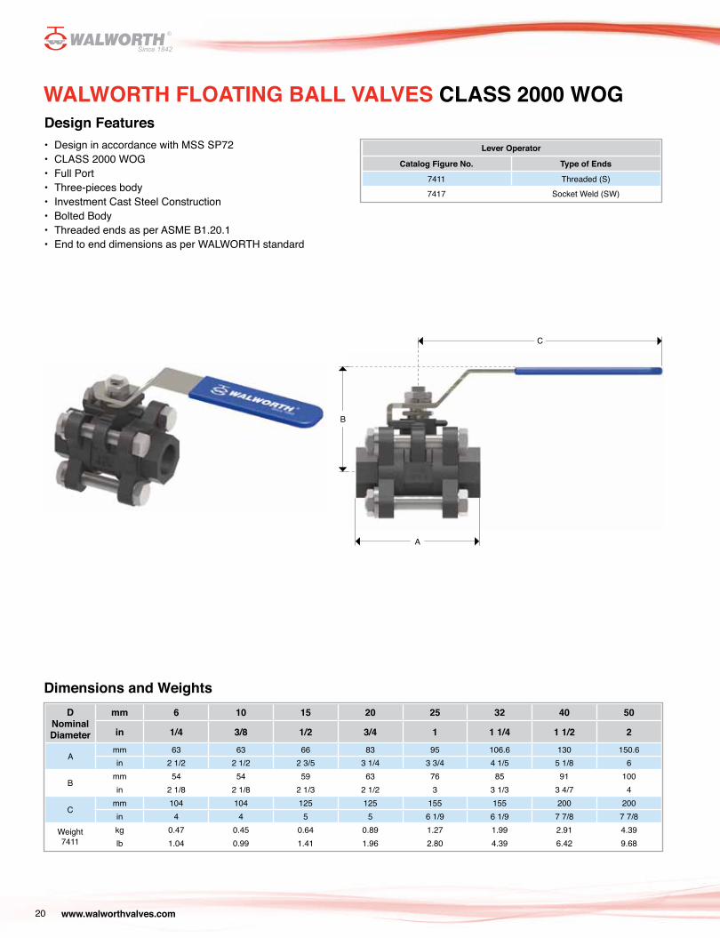
Design Features• Design in accordance with MSS SP72• CLASS 2000 WOG• Full Port• Three-pieces body• Investment Cast Steel Construction• Bolted Body• Threaded ends as per ASME B1.20.1• End to end dimensions as per WALWORTH standard
Lever Operator
Catalog Figure No. Type of Ends
7411 Threaded (S)7417 Socket Weld (SW)
Dimensions and WeightsD
Nominal Diameter
mm 6 10 15 20 25 32 40 50
in 1/4 3/8 1/2 3/4 1 1 1/4 1 1/2 2
Amm 63 63 66 83 95 106.6 130 150.6in 2 1/2 2 1/2 2 3/5 3 1/4 3 3/4 4 1/5 5 1/8 6
Bmm 54 54 59 63 76 85 91 100in 2 1/8 2 1/8 2 1/3 2 1/2 3 3 1/3 3 4/7 4
Cmm 104 104 125 125 155 155 200 200in 4 4 5 5 6 1/9 6 1/9 7 7/8 7 7/8
Weight7411
kg 0.47 0.45 0.64 0.89 1.27 1.99 2.91 4.39lb 1.04 0.99 1.41 1.96 2.80 4.39 6.42 9.68
WALWORTH FLOATING BALL VALVES CLASS 2000 WOG
C
B
A
www.walworthvalves.com 21
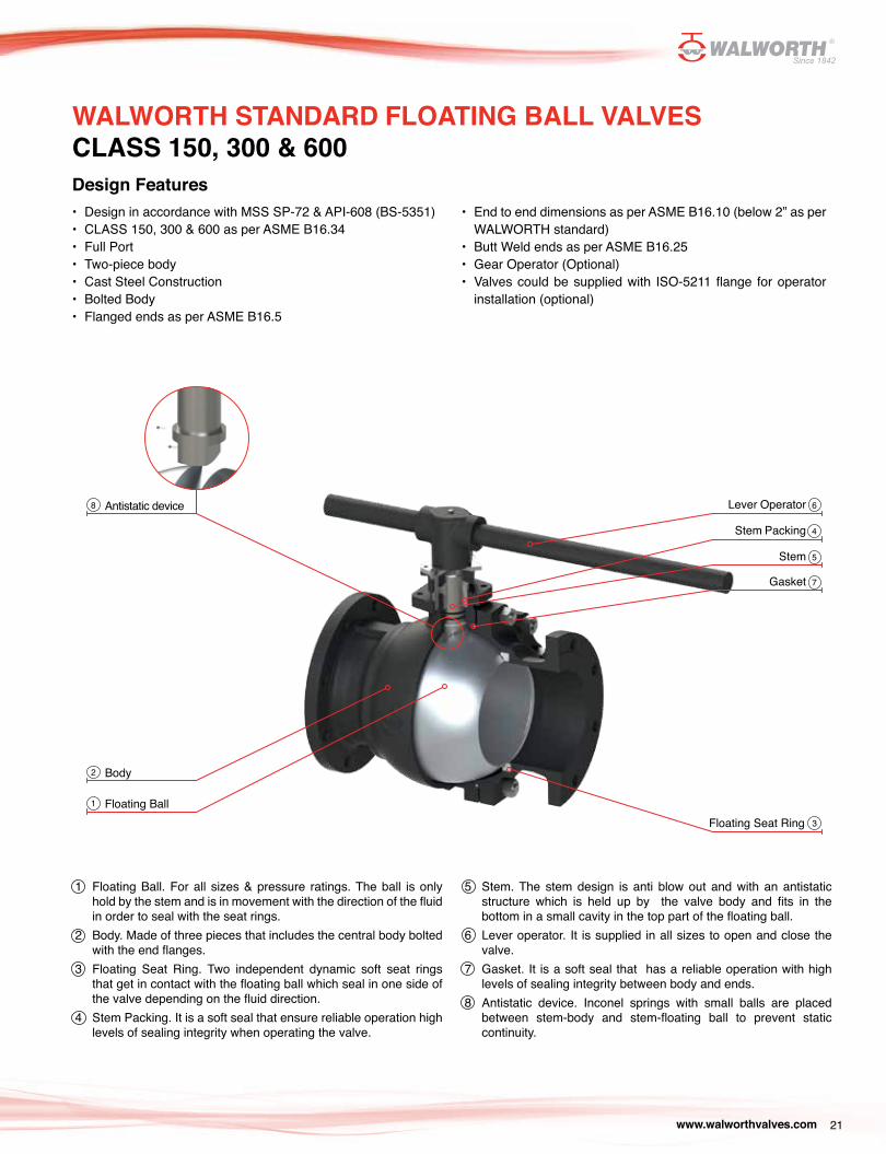
WALWORTH STANDARD FLOATING BALL VALVES CLASS 150, 300 & 600Design Features• Design in accordance with MSS SP-72 & API-608 (BS-5351)• CLASS 150, 300 & 600 as per ASME B16.34• Full Port• Two-piece body• Cast Steel Construction• Bolted Body• Flanged ends as per ASME B16.5
Antistatic device
Floating Ball
Body
Lever Operator
Stem Packing
Stem
Gasket
8
1
2
6
4
5
7
Floating Seat Ring 3
1 Floating Ball. For all sizes & pressure ratings. The ball is only hold by the stem and is in movement with the direction of the fluid in order to seal with the seat rings.
2 Body. Made of three pieces that includes the central body bolted with the end flanges.
3 Floating Seat Ring. Two independent dynamic soft seat rings that get in contact with the floating ball which seal in one side of the valve depending on the fluid direction.
4 Stem Packing. It is a soft seal that ensure reliable operation high levels of sealing integrity when operating the valve.
5 Stem. The stem design is anti blow out and with an antistatic structure which is held up by the valve body and fits in the bottom in a small cavity in the top part of the floating ball.
6 Lever operator. It is supplied in all sizes to open and close the valve.
7 Gasket. It is a soft seal that has a reliable operation with high levels of sealing integrity between body and ends.
8 Antistatic device. Inconel springs with small balls are placed between stem-body and stem-floating ball to prevent static continuity.
• End to end dimensions as per ASME B16.10 (below 2” as per WALWORTH standard)
• Butt Weld ends as per ASME B16.25• Gear Operator (Optional)• Valves could be supplied with ISO-5211 flange for operator
installation (optional)
www.walworthvalves.com22
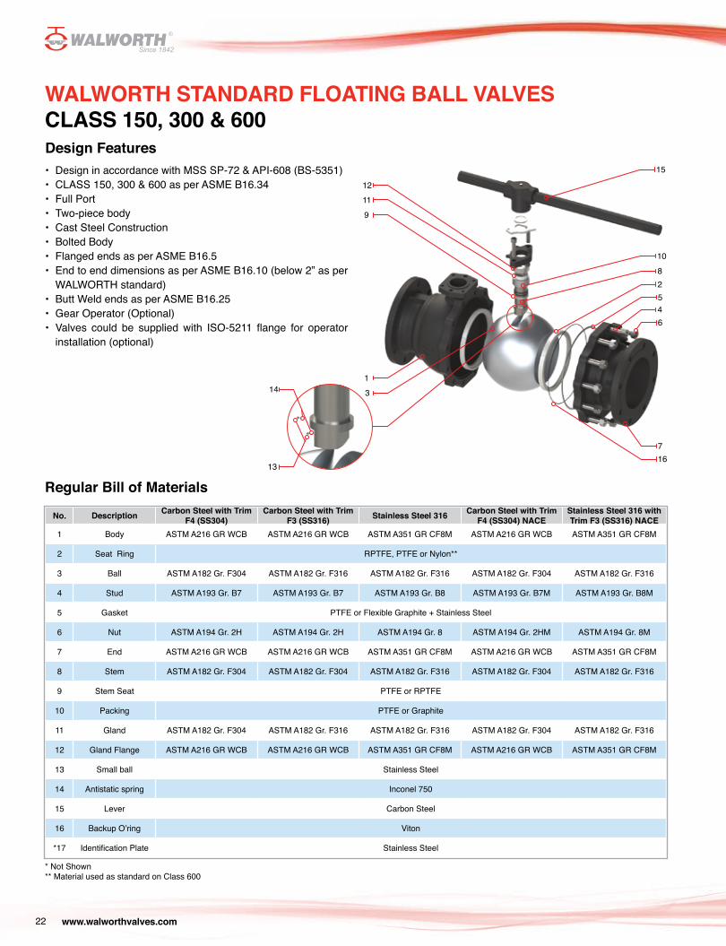
WALWORTH STANDARD FLOATING BALL VALVES CLASS 150, 300 & 600Design Features• Design in accordance with MSS SP-72 & API-608 (BS-5351)• CLASS 150, 300 & 600 as per ASME B16.34• Full Port• Two-piece body• Cast Steel Construction• Bolted Body• Flanged ends as per ASME B16.5• End to end dimensions as per ASME B16.10 (below 2” as per
WALWORTH standard)• Butt Weld ends as per ASME B16.25• Gear Operator (Optional)• Valves could be supplied with ISO-5211 flange for operator
installation (optional)
Regular Bill of Materials
No. Description Carbon Steel with Trim F4 (SS304)
Carbon Steel with Trim F3 (SS316) Stainless Steel 316 Carbon Steel with Trim
F4 (SS304) NACEStainless Steel 316 with Trim F3 (SS316) NACE
1 Body ASTM A216 GR WCB ASTM A216 GR WCB ASTM A351 GR CF8M ASTM A216 GR WCB ASTM A351 GR CF8M
2 Seat Ring RPTFE, PTFE or Nylon**
3 Ball ASTM A182 Gr. F304 ASTM A182 Gr. F316 ASTM A182 Gr. F316 ASTM A182 Gr. F304 ASTM A182 Gr. F316
4 Stud ASTM A193 Gr. B7 ASTM A193 Gr. B7 ASTM A193 Gr. B8 ASTM A193 Gr. B7M ASTM A193 Gr. B8M
5 Gasket PTFE or Flexible Graphite + Stainless Steel
6 Nut ASTM A194 Gr. 2H ASTM A194 Gr. 2H ASTM A194 Gr. 8 ASTM A194 Gr. 2HM ASTM A194 Gr. 8M
7 End ASTM A216 GR WCB ASTM A216 GR WCB ASTM A351 GR CF8M ASTM A216 GR WCB ASTM A351 GR CF8M
8 Stem ASTM A182 Gr. F304 ASTM A182 Gr. F304 ASTM A182 Gr. F316 ASTM A182 Gr. F304 ASTM A182 Gr. F316
9 Stem Seat PTFE or RPTFE
10 Packing PTFE or Graphite
11 Gland ASTM A182 Gr. F304 ASTM A182 Gr. F316 ASTM A182 Gr. F316 ASTM A182 Gr. F304 ASTM A182 Gr. F316
12 Gland Flange ASTM A216 GR WCB ASTM A216 GR WCB ASTM A351 GR CF8M ASTM A216 GR WCB ASTM A351 GR CF8M
13 Small ball Stainless Steel
14 Antistatic spring Inconel 750
15 Lever Carbon Steel
16 Backup O’ring Viton
*17 Identification Plate Stainless Steel
* Not Shown** Material used as standard on Class 600
1211
9
114
13
3
15
810
2
45
6
716
www.walworthvalves.com 23
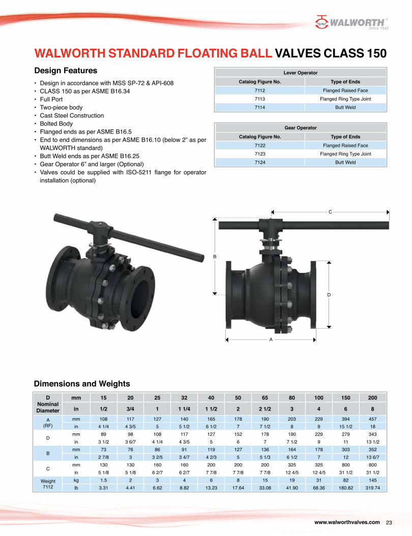
WALWORTH STANDARD FLOATING BALL VALVES CLASS 150Design Features• Design in accordance with MSS SP-72 & API-608• CLASS 150 as per ASME B16.34• Full Port• Two-piece body• Cast Steel Construction• Bolted Body• Flanged ends as per ASME B16.5• End to end dimensions as per ASME B16.10 (below 2” as per
WALWORTH standard)• Butt Weld ends as per ASME B16.25• Gear Operator 6” and larger (Optional)• Valves could be supplied with ISO-5211 flange for operator
installation (optional)
Lever Operator
Catalog Figure No. Type of Ends
7112 Flanged Raised Face 7113 Flanged Ring Type Joint 7114 Butt Weld
Gear Operator
Catalog Figure No. Type of Ends
7122 Flanged Raised Face 7123 Flanged Ring Type Joint 7124 Butt Weld
Dimensions and WeightsD
Nominal Diameter
mm 15 20 25 32 40 50 65 80 100 150 200
in 1/2 3/4 1 1 1/4 1 1/2 2 2 1/2 3 4 6 8
A(RF)
mm 108 117 127 140 165 178 190 203 229 394 457in 4 1/4 4 3/5 5 5 1/2 6 1/2 7 7 1/2 8 9 15 1/2 18
Dmm 89 98 108 117 127 152 178 190 229 279 343in 3 1/2 3 6/7 4 1/4 4 3/5 5 6 7 7 1/2 9 11 13 1/2
Bmm 73 76 86 91 119 127 136 164 178 303 352in 2 7/8 3 3 2/5 3 4/7 4 2/3 5 5 1/3 6 1/2 7 12 13 6/7
Cmm 130 130 160 160 200 200 200 325 325 800 800in 5 1/8 5 1/8 6 2/7 6 2/7 7 7/8 7 7/8 7 7/8 12 4/5 12 4/5 31 1/2 31 1/2
Weight7112
kg 1.5 2 3 4 6 8 15 19 31 82 145lb 3.31 4.41 6.62 8.82 13.23 17.64 33.08 41.90 68.36 180.82 319.74
C
B
D
A
www.walworthvalves.com24
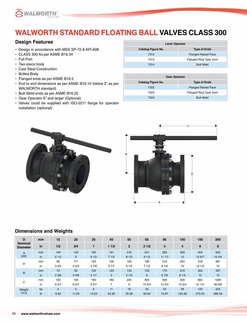
WALWORTH STANDARD FLOATING BALL VALVES CLASS 300Design Features• Design in accordance with MSS SP-72 & API-608• CLASS 300 As per ASME B16.34• Full Port• Two-piece body• Cast Steel Construction• Bolted Body• Flanged ends as per ASME B16.5• End to end dimensions as per ASME B16.10 (below 2” as per
WALWORTH standard)• Butt Weld ends as per ASME B16.25• Gear Operator 6” and larger (Optional)• Valves could be supplied with ISO-5211 flange for operator
installation (optional)
Lever Operator
Catalog Figure No. Type of Ends
7312 Flanged Raised Face 7313 Flanged Ring Type Joint 7314 Butt Weld
Gear Operator
Catalog Figure No. Type of Ends
7322 Flanged Raised Face 7323 Flanged Ring Type Joint 7324 Butt Weld
Dimensions and WeightsD
Nominal Diameter
mm 15 20 25 40 50 65 80 100 150 200
in 1/2 3/4 1 1 1/2 2 2 1/2 3 4 6 8
A(RF)
mm 140 152 165 191 216 241 283 305 403 502in 5 1/2 6 6 1/2 7 1/2 8 1/2 9 1/2 11 1/7 12 15 6/7 19 3/4
Dmm 95 117 124 156 165 190 210 254 318 381in 3 3/4 4 3/5 4 7/8 6 1/7 6 1/2 7 1/2 8 1/4 10 12 1/2 15
Bmm 72 92 105 125 135 153 172 210 303 357in 2 5/6 3 5/8 4 1/7 5 5 1/3 6 6 7/9 8 1/4 12 14
Cmm 160 160 160 180 230 400 400 400 800 1000in 6 2/7 6 2/7 6 2/7 7 9 15 3/4 15 3/4 15 3/4 31 1/2 39 3/8
Weight7312
kg 3 5 6 11 16 24 34 56 125 222lb 6.62 11.03 13.23 24.26 35.28 52.92 74.97 123.48 275.63 489.53
C
B
D
A
www.walworthvalves.com 25
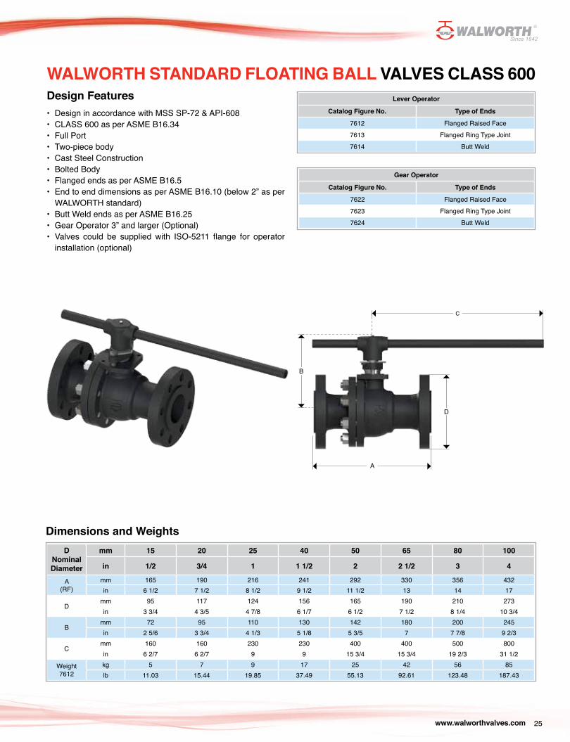
WALWORTH STANDARD FLOATING BALL VALVES CLASS 600Design Features• Design in accordance with MSS SP-72 & API-608• CLASS 600 as per ASME B16.34• Full Port• Two-piece body• Cast Steel Construction• Bolted Body• Flanged ends as per ASME B16.5• End to end dimensions as per ASME B16.10 (below 2” as per
WALWORTH standard)• Butt Weld ends as per ASME B16.25• Gear Operator 3” and larger (Optional)• Valves could be supplied with ISO-5211 flange for operator
installation (optional)
Lever Operator
Catalog Figure No. Type of Ends
7612 Flanged Raised Face 7613 Flanged Ring Type Joint 7614 Butt Weld
Gear Operator
Catalog Figure No. Type of Ends
7622 Flanged Raised Face 7623 Flanged Ring Type Joint 7624 Butt Weld
Dimensions and WeightsD
Nominal Diameter
mm 15 20 25 40 50 65 80 100
in 1/2 3/4 1 1 1/2 2 2 1/2 3 4
A(RF)
mm 165 190 216 241 292 330 356 432in 6 1/2 7 1/2 8 1/2 9 1/2 11 1/2 13 14 17
Dmm 95 117 124 156 165 190 210 273in 3 3/4 4 3/5 4 7/8 6 1/7 6 1/2 7 1/2 8 1/4 10 3/4
Bmm 72 95 110 130 142 180 200 245in 2 5/6 3 3/4 4 1/3 5 1/8 5 3/5 7 7 7/8 9 2/3
Cmm 160 160 230 230 400 400 500 800in 6 2/7 6 2/7 9 9 15 3/4 15 3/4 19 2/3 31 1/2
Weight7612
kg 5 7 9 17 25 42 56 85lb 11.03 15.44 19.85 37.49 55.13 92.61 123.48 187.43
C
B
A
D
www.walworthvalves.com26
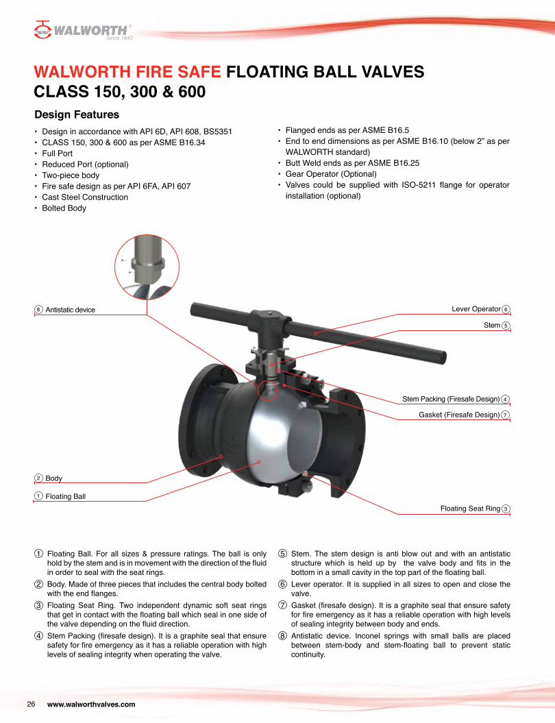
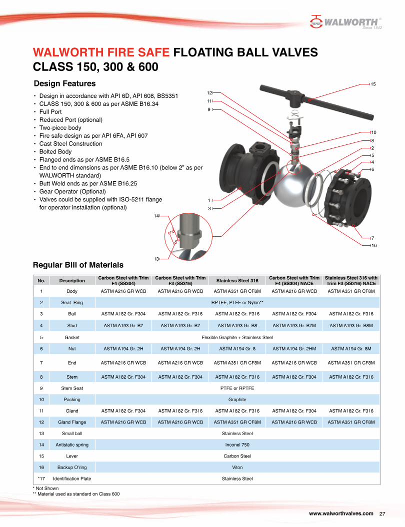
WALWORTH FIRE SAFE FLOATING BALL VALVES CLASS 150, 300 & 600Design Features • Design in accordance with API 6D, API 608, BS5351• CLASS 150, 300 & 600 as per ASME B16.34• Full Port• Reduced Port (optional)• Two-piece body• Fire safe design as per API 6FA, API 607• Cast Steel Construction• Bolted Body
Antistatic device
Floating Ball
Body
Lever Operator
Stem
Stem Packing (Firesafe Design)
Gasket (Firesafe Design)
Floating Seat Ring
8
1
2
6
5
4
7
3
• Flanged ends as per ASME B16.5• End to end dimensions as per ASME B16.10 (below 2” as per
WALWORTH standard)• Butt Weld ends as per ASME B16.25• Gear Operator (Optional)• Valves could be supplied with ISO-5211 flange for operator
installation (optional)
1 Floating Ball. For all sizes & pressure ratings. The ball is only hold by the stem and is in movement with the direction of the fluid in order to seal with the seat rings.
2 Body. Made of three pieces that includes the central body bolted with the end flanges.
3 Floating Seat Ring. Two independent dynamic soft seat rings that get in contact with the floating ball which seal in one side of the valve depending on the fluid direction.
4 Stem Packing (firesafe design). It is a graphite seal that ensure safety for fire emergency as it has a reliable operation with high levels of sealing integrity when operating the valve.
5 Stem. The stem design is anti blow out and with an antistatic structure which is held up by the valve body and fits in the bottom in a small cavity in the top part of the floating ball.
6 Lever operator. It is supplied in all sizes to open and close the valve.
7 Gasket (firesafe design). It is a graphite seal that ensure safety for fire emergency as it has a reliable operation with high levels of sealing integrity between body and ends.
8 Antistatic device. Inconel springs with small balls are placed between stem-body and stem-floating ball to prevent static continuity.
www.walworthvalves.com 27
WALWORTH FIRE SAFE FLOATING BALL VALVES CLASS 150, 300 & 600Design Features • Design in accordance with API 6D, API 608, BS5351• CLASS 150, 300 & 600 as per ASME B16.34• Full Port• Reduced Port (optional)• Two-piece body• Fire safe design as per API 6FA, API 607• Cast Steel Construction• Bolted Body• Flanged ends as per ASME B16.5• End to end dimensions as per ASME B16.10 (below 2” as per
WALWORTH standard)• Butt Weld ends as per ASME B16.25• Gear Operator (Optional)• Valves could be supplied with ISO-5211 flange
for operator installation (optional)
Regular Bill of Materials
No. Description Carbon Steel with Trim F4 (SS304)
Carbon Steel with Trim F3 (SS316) Stainless Steel 316 Carbon Steel with Trim
F4 (SS304) NACEStainless Steel 316 with Trim F3 (SS316) NACE
1 Body ASTM A216 GR WCB ASTM A216 GR WCB ASTM A351 GR CF8M ASTM A216 GR WCB ASTM A351 GR CF8M
2 Seat Ring RPTFE, PTFE or Nylon**
3 Ball ASTM A182 Gr. F304 ASTM A182 Gr. F316 ASTM A182 Gr. F316 ASTM A182 Gr. F304 ASTM A182 Gr. F316
4 Stud ASTM A193 Gr. B7 ASTM A193 Gr. B7 ASTM A193 Gr. B8 ASTM A193 Gr. B7M ASTM A193 Gr. B8M
5 Gasket Flexible Graphite + Stainless Steel
6 Nut ASTM A194 Gr. 2H ASTM A194 Gr. 2H ASTM A194 Gr. 8 ASTM A194 Gr. 2HM ASTM A194 Gr. 8M
7 End ASTM A216 GR WCB ASTM A216 GR WCB ASTM A351 GR CF8M ASTM A216 GR WCB ASTM A351 GR CF8M
8 Stem ASTM A182 Gr. F304 ASTM A182 Gr. F304 ASTM A182 Gr. F316 ASTM A182 Gr. F304 ASTM A182 Gr. F316
9 Stem Seat PTFE or RPTFE
10 Packing Graphite
11 Gland ASTM A182 Gr. F304 ASTM A182 Gr. F316 ASTM A182 Gr. F316 ASTM A182 Gr. F304 ASTM A182 Gr. F316
12 Gland Flange ASTM A216 GR WCB ASTM A216 GR WCB ASTM A351 GR CF8M ASTM A216 GR WCB ASTM A351 GR CF8M
13 Small ball Stainless Steel
14 Antistatic spring Inconel 750
15 Lever Carbon Steel
16 Backup O’ring Viton
*17 Identification Plate Stainless Steel
* Not Shown** Material used as standard on Class 600
1211
9
13
15
810
2
45
6
716
14
13
www.walworthvalves.com28
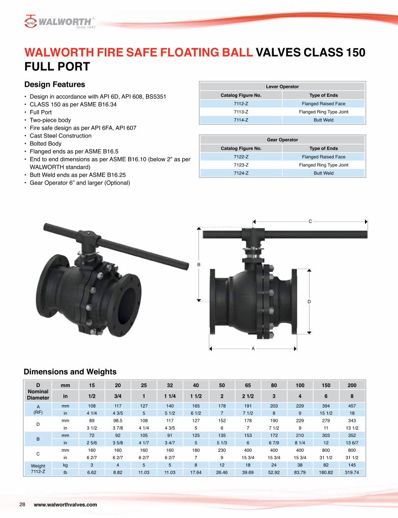
WALWORTH FIRE SAFE FLOATING BALL VALVES CLASS 150 FULL PORTDesign Features • Design in accordance with API 6D, API 608, BS5351• CLASS 150 as per ASME B16.34• Full Port• Two-piece body• Fire safe design as per API 6FA, API 607• Cast Steel Construction• Bolted Body• Flanged ends as per ASME B16.5• End to end dimensions as per ASME B16.10 (below 2” as per
WALWORTH standard)• Butt Weld ends as per ASME B16.25• Gear Operator 6” and larger (Optional)
Lever Operator
Catalog Figure No. Type of Ends
7112-Z Flanged Raised Face 7113-Z Flanged Ring Type Joint 7114-Z Butt Weld
Gear Operator
Catalog Figure No. Type of Ends
7122-Z Flanged Raised Face 7123-Z Flanged Ring Type Joint 7124-Z Butt Weld
Dimensions and WeightsD
Nominal Diameter
mm 15 20 25 32 40 50 65 80 100 150 200
in 1/2 3/4 1 1 1/4 1 1/2 2 2 1/2 3 4 6 8
A(RF)
mm 108 117 127 140 165 178 191 203 229 394 457in 4 1/4 4 3/5 5 5 1/2 6 1/2 7 7 1/2 8 9 15 1/2 18
Dmm 89 98.5 108 117 127 152 178 190 229 279 343in 3 1/2 3 7/8 4 1/4 4 3/5 5 6 7 7 1/2 9 11 13 1/2
Bmm 72 92 105 91 125 135 153 172 210 303 352in 2 5/6 3 5/8 4 1/7 3 4/7 5 5 1/3 6 6 7/9 8 1/4 12 13 6/7
Cmm 160 160 160 160 180 230 400 400 400 800 800in 6 2/7 6 2/7 6 2/7 6 2/7 7 9 15 3/4 15 3/4 15 3/4 31 1/2 31 1/2
Weight7112-Z
kg 3 4 5 5 8 12 18 24 38 82 145lb 6.62 8.82 11.03 11.03 17.64 26.46 39.69 52.92 83.79 180.82 319.74
C
B
D
A
www.walworthvalves.com 29
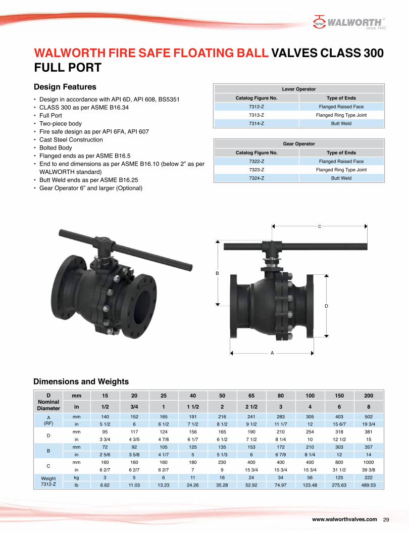
WALWORTH FIRE SAFE FLOATING BALL VALVES CLASS 300 FULL PORTDesign Features • Design in accordance with API 6D, API 608, BS5351• CLASS 300 as per ASME B16.34• Full Port• Two-piece body• Fire safe design as per API 6FA, API 607• Cast Steel Construction• Bolted Body• Flanged ends as per ASME B16.5• End to end dimensions as per ASME B16.10 (below 2” as per
WALWORTH standard)• Butt Weld ends as per ASME B16.25• Gear Operator 6” and larger (Optional)
Lever Operator
Catalog Figure No. Type of Ends
7312-Z Flanged Raised Face 7313-Z Flanged Ring Type Joint 7314-Z Butt Weld
Gear Operator
Catalog Figure No. Type of Ends
7322-Z Flanged Raised Face 7323-Z Flanged Ring Type Joint 7324-Z Butt Weld
Dimensions and WeightsD
Nominal Diameter
mm 15 20 25 40 50 65 80 100 150 200
in 1/2 3/4 1 1 1/2 2 2 1/2 3 4 6 8
A(RF)
mm 140 152 165 191 216 241 283 305 403 502in 5 1/2 6 6 1/2 7 1/2 8 1/2 9 1/2 11 1/7 12 15 6/7 19 3/4
Dmm 95 117 124 156 165 190 210 254 318 381in 3 3/4 4 3/5 4 7/8 6 1/7 6 1/2 7 1/2 8 1/4 10 12 1/2 15
Bmm 72 92 105 125 135 153 172 210 303 357in 2 5/6 3 5/8 4 1/7 5 5 1/3 6 6 7/9 8 1/4 12 14
Cmm 160 160 160 180 230 400 400 400 800 1000in 6 2/7 6 2/7 6 2/7 7 9 15 3/4 15 3/4 15 3/4 31 1/2 39 3/8
Weight7312-Z
kg 3 5 6 11 16 24 34 56 125 222lb 6.62 11.03 13.23 24.26 35.28 52.92 74.97 123.48 275.63 489.53
C
B
D
A
www.walworthvalves.com30
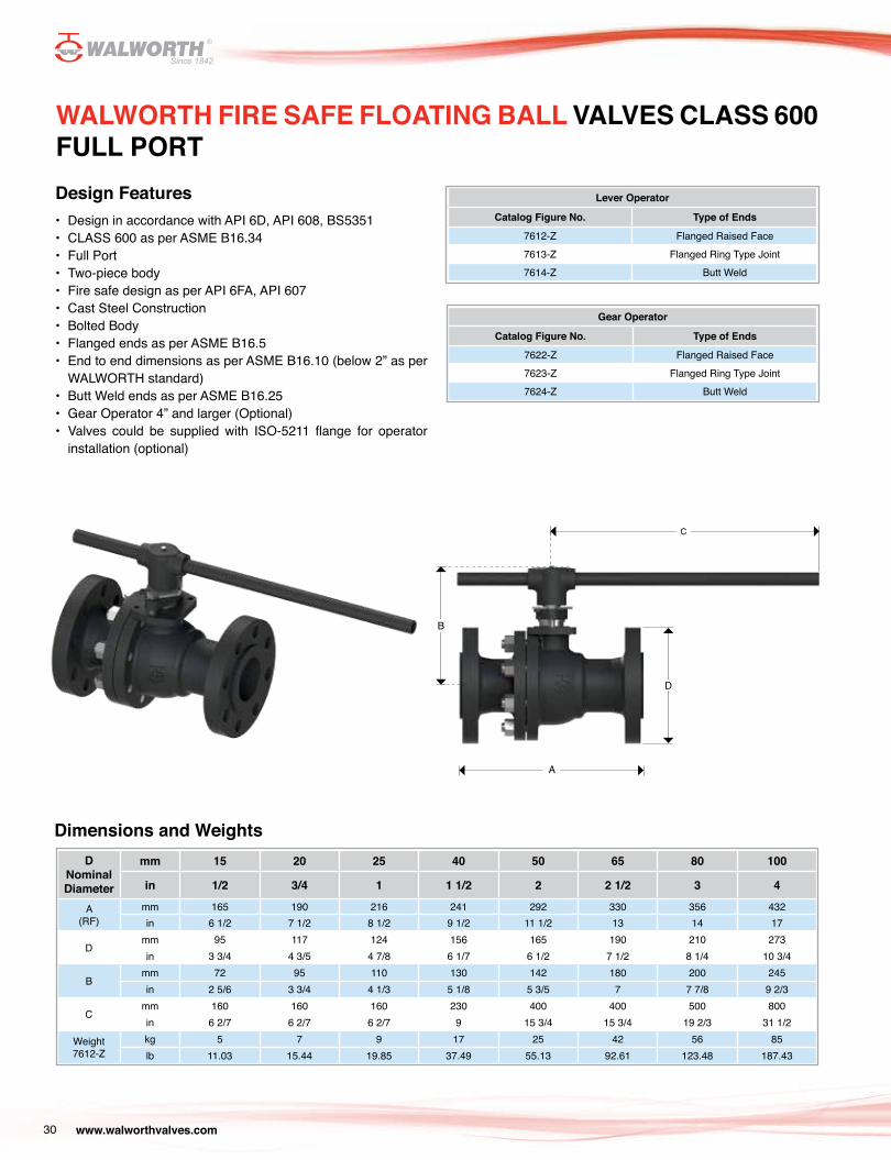
WALWORTH FIRE SAFE FLOATING BALL VALVES CLASS 600 FULL PORTDesign Features• Design in accordance with API 6D, API 608, BS5351• CLASS 600 as per ASME B16.34• Full Port• Two-piece body• Fire safe design as per API 6FA, API 607• Cast Steel Construction• Bolted Body• Flanged ends as per ASME B16.5• End to end dimensions as per ASME B16.10 (below 2” as per
WALWORTH standard)• Butt Weld ends as per ASME B16.25• Gear Operator 4” and larger (Optional)• Valves could be supplied with ISO-5211 flange for operator
installation (optional)
Lever Operator
Catalog Figure No. Type of Ends
7612-Z Flanged Raised Face 7613-Z Flanged Ring Type Joint 7614-Z Butt Weld
Gear Operator
Catalog Figure No. Type of Ends
7622-Z Flanged Raised Face 7623-Z Flanged Ring Type Joint 7624-Z Butt Weld
Dimensions and WeightsD
Nominal Diameter
mm 15 20 25 40 50 65 80 100
in 1/2 3/4 1 1 1/2 2 2 1/2 3 4
A(RF)
mm 165 190 216 241 292 330 356 432in 6 1/2 7 1/2 8 1/2 9 1/2 11 1/2 13 14 17
Dmm 95 117 124 156 165 190 210 273in 3 3/4 4 3/5 4 7/8 6 1/7 6 1/2 7 1/2 8 1/4 10 3/4
Bmm 72 95 110 130 142 180 200 245in 2 5/6 3 3/4 4 1/3 5 1/8 5 3/5 7 7 7/8 9 2/3
Cmm 160 160 160 230 400 400 500 800in 6 2/7 6 2/7 6 2/7 9 15 3/4 15 3/4 19 2/3 31 1/2
Weight7612-Z
kg 5 7 9 17 25 42 56 85lb 11.03 15.44 19.85 37.49 55.13 92.61 123.48 187.43
C
B
A
D

www.walworthvalves.com 31
B
WALWORTH FIRE SAFE FLOATING BALL VALVES CLASS 150 REDUCED PORT Design Features • Design in accordance with API 6D, API 608, BS5351• CLASS 150 as per ASME B16.34• Reduced Port • Two-piece body• Fire safe design as per API 6FA, API 607• Cast Steel Construction• Bolted Body• Flanged ends as per ASME B16.5• End to end dimensions as per ASME B16.10 (below 2” as per
WALWORTH standard)• Butt Weld ends as per ASME B16.25• Gear Operator 6” X 4” and larger (Optional)
Lever Operator
Catalog Figure No. Type of Ends
7112-RZ Flanged Raised Face 7113-RZ Flanged Ring Type Joint 7114-RZ Butt Weld
Gear Operator
Catalog Figure No. Type of Ends
7122-RZ Flanged Raised Face 7123-RZ Flanged Ring Type Joint 7124-RZ Butt Weld
Dimensions and WeightsD
Nominal Diameter
mm 15 X 10 20 X 15 25 X 20 50 X 40 80 X 50 100 X 80 150 X 100 200 X 150
in 1/2 X 3/8 3/4 X 1/2 1 X 3/4 2 X 1 1/2 3 X 2 4 X 3 6 X 4 8 X 6
A(RF)
mm 108 117 127 178 203 229 394 457in 4 1/4 4 3/5 5 7 8 9 15 1/2 18
Dmm 89 98.5 108 152 190 229 279 343in 3 1/2 3 7/8 4 1/4 6 7 1/2 9 11 13 1/2
Bmm 72 72 92 125 135 172 210 303in 2 5/6 2 5/6 3 5/8 5 5 1/3 6 7/9 8 1/4 12
Cmm 160 160 160 180 230 400 400 800in 6 2/7 6 2/7 6 2/7 7 9 15 3/4 15 3/4 31 1/2
Weight7112-RZ
kg 3 3.5 5 9 15 25 60 105lb 6.62 7.72 11.03 19.85 33.08 55.13 132.30 231.53
C
A
D

www.walworthvalves.com32
WALWORTH FIRE SAFE FLOATING BALL VALVES CLASS 300 REDUCED PORT Design Features• Design in accordance with API 6D, API 608, BS5351• CLASS 300 as per ASME B16.34• Reduced Port • Two-piece body• Fire safe design as per API 6FA, API 607• Cast Steel Construction• Bolted Body• Flanged ends as per ASME B16.5• End to end dimensions as per ASME B16.10 (below 2” as per
WALWORTH standard)• Butt Weld ends as per ASME B16.25• Gear Operator 6” X 4” and larger (Optional)
Lever Operator (Reduced Port)
Catalog Figure No. Type of Ends
7312-RZ Flanged Raised Face 7313-RZ Flanged Ring Type Joint 7314-RZ Butt Weld
Gear Operator (Reduced Port)
Catalog Figure No. Type of Ends
7322-RZ Flanged Raised Face 7323-RZ Flanged Ring Type Joint 7324-RZ Butt Weld
Dimensions and WeightsD
Nominal Diameter
mm 15 X 10 20 X 15 25 X 20 50 X 40 80 X 50 100 X 80 150 X 100 200 X 150
in 1/2 X 3/8 3/4 X 1/2 1 X 3/4 2 X 1 1/2 3 X 2 4 X 3 6 X 4 8 X 6
A(RF)
mm 108 117 127 178 203 229 394 457in 4 1/4 4 3/5 5 7 8 9 15 1/2 18
Dmm 89 98.5 108 152 190 229 279 343in 3 1/2 3 7/8 4 1/4 6 7 1/2 9 11 13 1/2
Bmm 72 72 92 125 135 172 210 303in 2 5/6 2 5/6 3 5/8 5 5 1/3 6 7/9 8 1/4 12
Cmm 160 160 160 180 230 400 400 800in 6 2/7 6 2/7 6 2/7 7 9 15 3/4 15 3/4 31 1/2
Weight7312-RZ
kg 4 5 6 14 25 48 90 130lb 8.82 11.03 13.23 30.87 55.13 105.84 198.46 286.66
C
B
A
D
www.walworthvalves.com 33
C
B
A
D
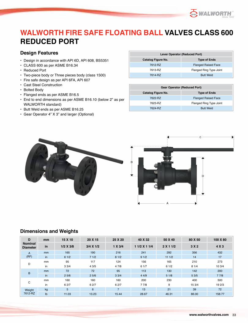
WALWORTH FIRE SAFE FLOATING BALL VALVES CLASS 600 REDUCED PORT Design Features• Design in accordance with API 6D, API 608, BS5351• CLASS 600 as per ASME B16.34• Reduced Port • Two-piece body or Three pieces body (class 1500)• Fire safe design as per API 6FA, API 607• Cast Steel Construction• Bolted Body• Flanged ends as per ASME B16.5• End to end dimensions as per ASME B16.10 (below 2” as per
WALWORTH standard)• Butt Weld ends as per ASME B16.25• Gear Operator 4” X 3” and larger (Optional)
Lever Operator (Reduced Port)
Catalog Figure No. Type of Ends
7612-RZ Flanged Raised Face 7613-RZ Flanged Ring Type Joint 7614-RZ Butt Weld
Gear Operator (Reduced Port)
Catalog Figure No. Type of Ends
7622-RZ Flanged Raised Face 7623-RZ Flanged Ring Type Joint 7624-RZ Butt Weld
Dimensions and WeightsD
Nominal Diameter
mm 15 X 10 20 X 15 25 X 20 40 X 32 50 X 40 80 X 50 100 X 80
in 1/2 X 3/8 3/4 X 1/2 1 X 3/4 1 1/2 X 1 1/4 2 X 1 1/2 3 X 2 4 X 3
A(RF)
mm 165 190 216 241 292 356 432in 6 1/2 7 1/2 8 1/2 9 1/2 11 1/2 14 17
Dmm 95 117 124 156 165 210 273in 3 3/4 4 3/5 4 7/8 6 1/7 6 1/2 8 1/4 10 3/4
Bmm 72 72 95 113 130 142 200in 2 5/6 2 5/6 3 3/4 4 4/9 5 1/8 5 3/5 7 7/8
Cmm 160 160 160 200 230 400 500in 6 2/7 6 2/7 6 2/7 7 7/8 9 15 3/4 19 2/3
Weight7612-RZ
kg 5 6 7 13 21 39 72lb 11.03 13.23 15.44 28.67 46.31 86.00 158.77
www.walworthvalves.com34
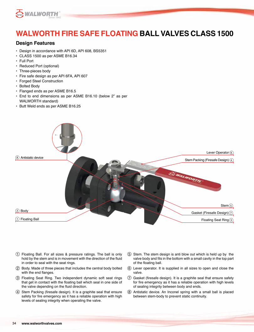
WALWORTH FIRE SAFE FLOATING BALL VALVES CLASS 1500Design Features• Design in accordance with API 6D, API 608, BS5351• CLASS 1500 as per ASME B16.34• Full Port• Reduced Port (optional)• Three-pieces body• Fire safe design as per API 6FA, API 607• Forged Steel Construction• Bolted Body• Flanged ends as per ASME B16.5• End to end dimensions as per ASME B16.10 (below 2” as per
WALWORTH standard)• Butt Weld ends as per ASME B16.25
Antistatic device
Floating Ball
Body
Lever Operator
Stem Packing (Firesafe Design)
Stem
Gasket (Firesafe Design)
Floating Seat Ring
8
1
2
6
4
5
7
3
1 Floating Ball. For all sizes & pressure ratings. The ball is only hold by the stem and is in movement with the direction of the fluid in order to seal with the seat rings.
2 Body. Made of three pieces that includes the central body bolted with the end flanges.
3 Floating Seat Ring. Two independent dynamic soft seat rings that get in contact with the floating ball which seal in one side of the valve depending on the fluid direction.
4 Stem Packing (firesafe design). It is a graphite seal that ensure safety for fire emergency as it has a reliable operation with high levels of sealing integrity when operating the valve.
5 Stem. The stem design is anti blow out which is held up by the valve body and fits in the bottom with a small cavity in the top part of the floating ball.
6 Lever operator. It is supplied in all sizes to open and close the valve.
7 Gasket (firesafe design). It is a graphite seal that ensure safety for fire emergency as it has a reliable operation with high levels of sealing integrity between body and ends.
8 Antistatic device. An Inconel spring with a small ball is placed between stem-body to prevent static continuity.
www.walworthvalves.com 35
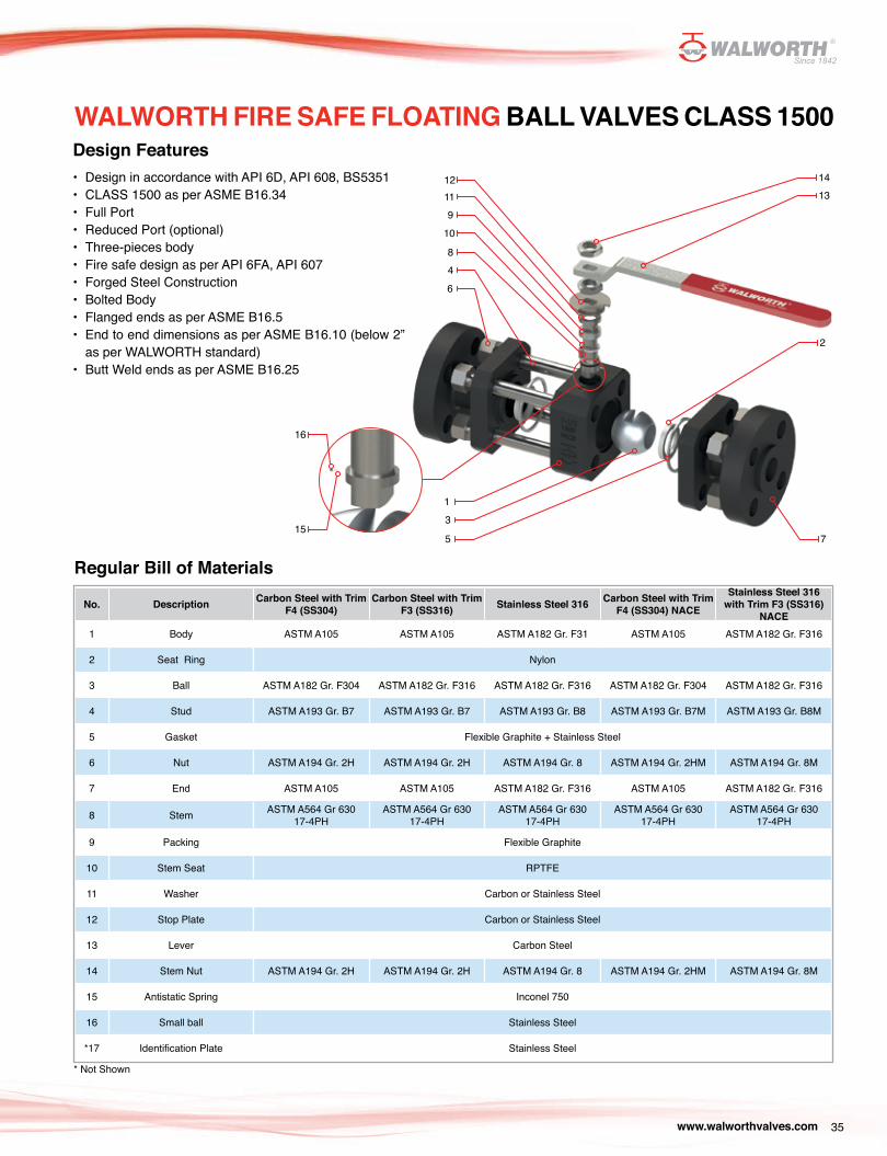
Design Features• Design in accordance with API 6D, API 608, BS5351• CLASS 1500 as per ASME B16.34• Full Port• Reduced Port (optional)• Three-pieces body• Fire safe design as per API 6FA, API 607• Forged Steel Construction• Bolted Body• Flanged ends as per ASME B16.5• End to end dimensions as per ASME B16.10 (below 2”
as per WALWORTH standard)• Butt Weld ends as per ASME B16.25
Regular Bill of Materials
No. Description Carbon Steel with Trim F4 (SS304)
Carbon Steel with Trim F3 (SS316) Stainless Steel 316 Carbon Steel with Trim
F4 (SS304) NACE
Stainless Steel 316 with Trim F3 (SS316)
NACE1 Body ASTM A105 ASTM A105 ASTM A182 Gr. F31 ASTM A105 ASTM A182 Gr. F316
2 Seat Ring Nylon
3 Ball ASTM A182 Gr. F304 ASTM A182 Gr. F316 ASTM A182 Gr. F316 ASTM A182 Gr. F304 ASTM A182 Gr. F316
4 Stud ASTM A193 Gr. B7 ASTM A193 Gr. B7 ASTM A193 Gr. B8 ASTM A193 Gr. B7M ASTM A193 Gr. B8M
5 Gasket Flexible Graphite + Stainless Steel
6 Nut ASTM A194 Gr. 2H ASTM A194 Gr. 2H ASTM A194 Gr. 8 ASTM A194 Gr. 2HM ASTM A194 Gr. 8M
7 End ASTM A105 ASTM A105 ASTM A182 Gr. F316 ASTM A105 ASTM A182 Gr. F316
8 Stem ASTM A564 Gr 630 17-4PH
ASTM A564 Gr 630 17-4PH
ASTM A564 Gr 630 17-4PH
ASTM A564 Gr 630 17-4PH
ASTM A564 Gr 630 17-4PH
9 Packing Flexible Graphite
10 Stem Seat RPTFE
11 Washer Carbon or Stainless Steel
12 Stop Plate Carbon or Stainless Steel
13 Lever Carbon Steel
14 Stem Nut ASTM A194 Gr. 2H ASTM A194 Gr. 2H ASTM A194 Gr. 8 ASTM A194 Gr. 2HM ASTM A194 Gr. 8M
15 Antistatic Spring Inconel 750
16 Small ball Stainless Steel
*17 Identification Plate Stainless Steel
* Not Shown
WALWORTH FIRE SAFE FLOATING BALL VALVES CLASS 1500
8
1112
4
9
6
10
13
5
1413
2
7
16
15
www.walworthvalves.com36
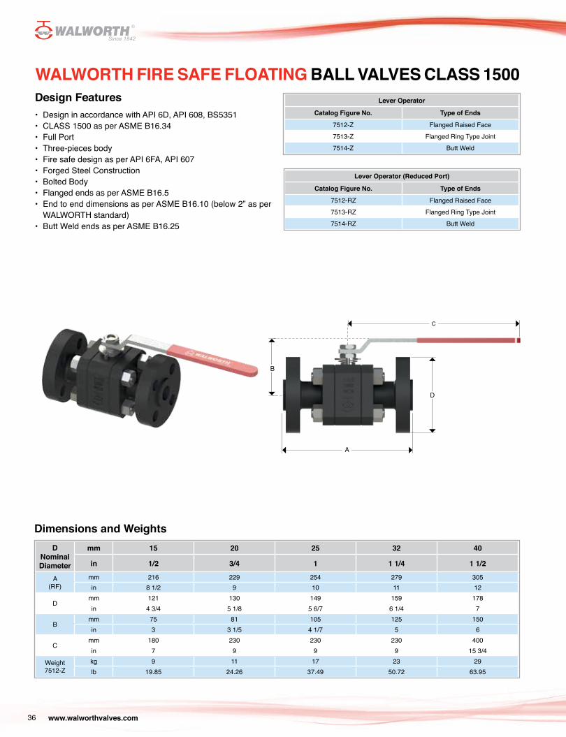
WALWORTH FIRE SAFE FLOATING BALL VALVES CLASS 1500Design Features• Design in accordance with API 6D, API 608, BS5351• CLASS 1500 as per ASME B16.34• Full Port• Three-pieces body• Fire safe design as per API 6FA, API 607• Forged Steel Construction• Bolted Body• Flanged ends as per ASME B16.5• End to end dimensions as per ASME B16.10 (below 2” as per
WALWORTH standard)• Butt Weld ends as per ASME B16.25
Lever Operator
Catalog Figure No. Type of Ends
7512-Z Flanged Raised Face 7513-Z Flanged Ring Type Joint 7514-Z Butt Weld
Lever Operator (Reduced Port)
Catalog Figure No. Type of Ends
7512-RZ Flanged Raised Face 7513-RZ Flanged Ring Type Joint 7514-RZ Butt Weld
Dimensions and WeightsD
Nominal Diameter
mm 15 20 25 32 40
in 1/2 3/4 1 1 1/4 1 1/2
A(RF)
mm 216 229 254 279 305in 8 1/2 9 10 11 12
Dmm 121 130 149 159 178in 4 3/4 5 1/8 5 6/7 6 1/4 7
Bmm 75 81 105 125 150in 3 3 1/5 4 1/7 5 6
Cmm 180 230 230 230 400in 7 9 9 9 15 3/4
Weight7512-Z
kg 9 11 17 23 29lb 19.85 24.26 37.49 50.72 63.95
C
B
A
D
www.walworthvalves.com 37
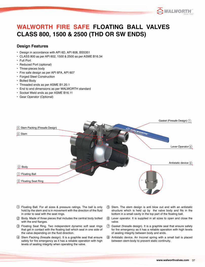
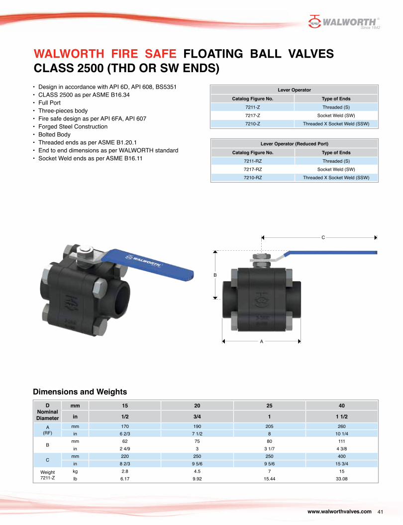
WALWORTH FIRE SAFE FLOATING BALL VALVES CLASS 800, 1500 & 2500 (THD OR SW ENDS)
Gasket (Firesafe Design)
Stem Packing (Firesafe Design)
Stem
Floating Seat Ring
Floating Ball
BodyAntistatic device
Lever Operator
Design Features• Design in accordance with API 6D, API 608, BS5351• CLASS 800 as per API 602, 1500 & 2500 as per ASME B16.34 • Full Port• Reduced Port (optional)• Three-pieces body• Fire safe design as per API 6FA, API 607• Forged Steel Construction• Bolted Body• Threaded ends as per ASME B1.20.1• End to end dimensions as per WALWORTH standard• Socket Weld ends as per ASME B16.11• Gear Operator (Optional)
1 Floating Ball. For all sizes & pressure ratings. The ball is only hold by the stem and is in movement with the direction of the fluid in order to seal with the seat rings.
2 Body. Made of three pieces that includes the central body bolted with the end flanges.
3 Floating Seat Ring. Two independent dynamic soft seat rings that get in contact with the floating ball which seal in one side of the valve depending on the fluid direction.
4 Stem Packing (firesafe design). It is a graphite seal that ensure safety for fire emergency as it has a reliable operation with high levels of sealing integrity when operating the valve.
5 Stem. The stem design is anti blow out and with an antistatic structure which is held up by the valve body and fits in the bottom in a small cavity in the top part of the floating ball.
6 Lever operator. It is supplied in all sizes to open and close the valve.
7 Gasket (firesafe design). It is a graphite seal that ensure safety for fire emergency as it has a reliable operation with high levels of sealing integrity between body and ends.
8 Antistatic device. An Inconel spring with a small ball is placed between stem-body to prevent static continuity.
7
4
5
3
1
2
8
6
www.walworthvalves.com38
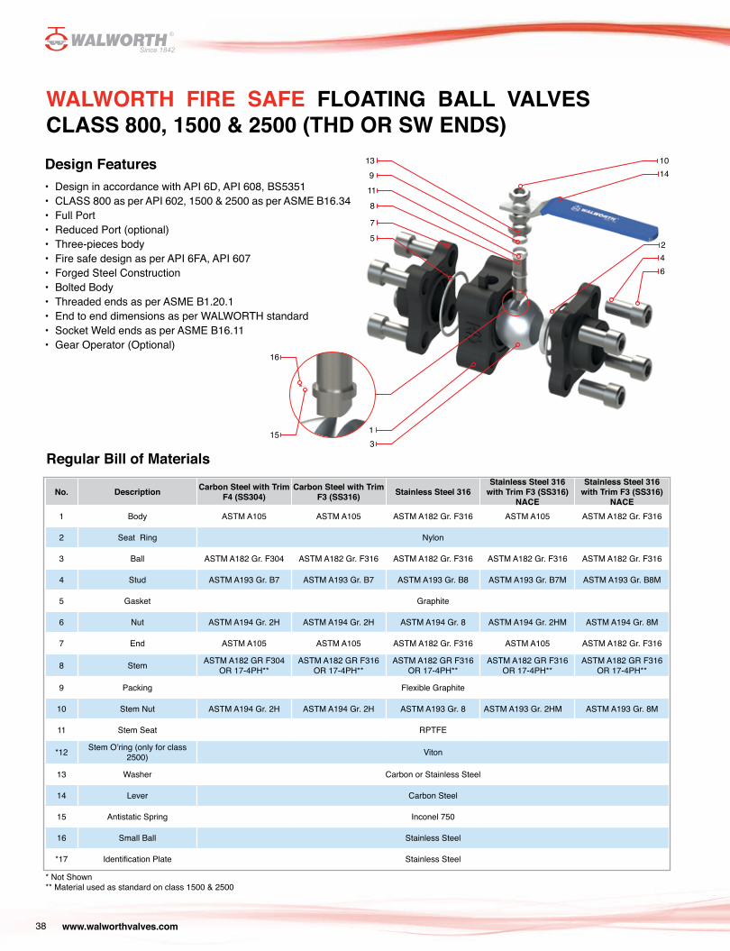
Design Features• Design in accordance with API 6D, API 608, BS5351• CLASS 800 as per API 602, 1500 & 2500 as per ASME B16.34 • Full Port• Reduced Port (optional)• Three-pieces body• Fire safe design as per API 6FA, API 607• Forged Steel Construction• Bolted Body• Threaded ends as per ASME B1.20.1• End to end dimensions as per WALWORTH standard• Socket Weld ends as per ASME B16.11• Gear Operator (Optional)
Regular Bill of Materials
No. Description Carbon Steel with Trim F4 (SS304)
Carbon Steel with Trim F3 (SS316) Stainless Steel 316
Stainless Steel 316 with Trim F3 (SS316)
NACE
Stainless Steel 316 with Trim F3 (SS316)
NACE1 Body ASTM A105 ASTM A105 ASTM A182 Gr. F316 ASTM A105 ASTM A182 Gr. F316
2 Seat Ring Nylon
3 Ball ASTM A182 Gr. F304 ASTM A182 Gr. F316 ASTM A182 Gr. F316 ASTM A182 Gr. F316 ASTM A182 Gr. F316
4 Stud ASTM A193 Gr. B7 ASTM A193 Gr. B7 ASTM A193 Gr. B8 ASTM A193 Gr. B7M ASTM A193 Gr. B8M
5 Gasket Graphite
6 Nut ASTM A194 Gr. 2H ASTM A194 Gr. 2H ASTM A194 Gr. 8 ASTM A194 Gr. 2HM ASTM A194 Gr. 8M
7 End ASTM A105 ASTM A105 ASTM A182 Gr. F316 ASTM A105 ASTM A182 Gr. F316
8 Stem ASTM A182 GR F304 OR 17-4PH**
ASTM A182 GR F316 OR 17-4PH**
ASTM A182 GR F316 OR 17-4PH**
ASTM A182 GR F316 OR 17-4PH**
ASTM A182 GR F316 OR 17-4PH**
9 Packing Flexible Graphite
10 Stem Nut ASTM A194 Gr. 2H ASTM A194 Gr. 2H ASTM A193 Gr. 8 ASTM A193 Gr. 2HM ASTM A193 Gr. 8M
11 Stem Seat RPTFE
*12 Stem O’ring (only for class 2500) Viton
13 Washer Carbon or Stainless Steel
14 Lever Carbon Steel
15 Antistatic Spring Inconel 750
16 Small Ball Stainless Steel
*17 Identification Plate Stainless Steel
* Not Shown** Material used as standard on class 1500 & 2500
WALWORTH FIRE SAFE FLOATING BALL VALVES CLASS 800, 1500 & 2500 (THD OR SW ENDS)
13
8
7
5
9
11
13
1014
42
6
16
15
www.walworthvalves.com 39
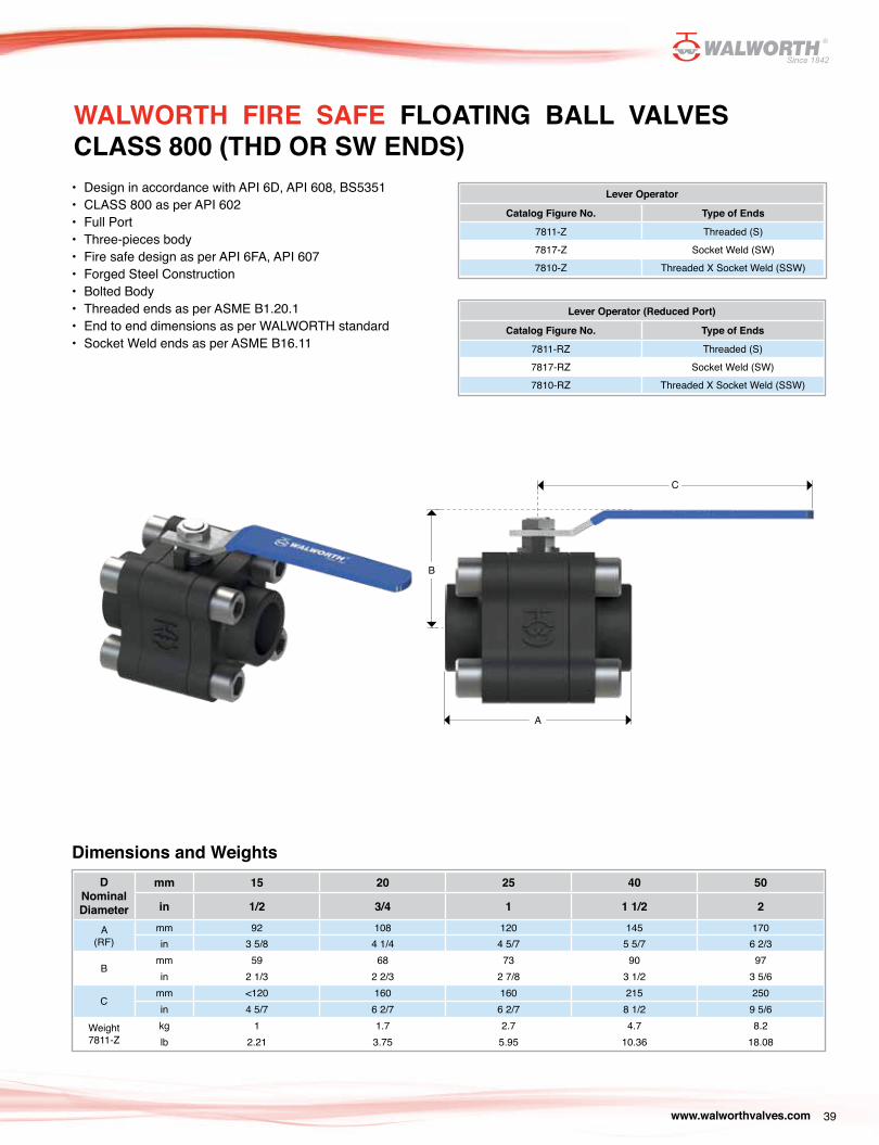
• Design in accordance with API 6D, API 608, BS5351• CLASS 800 as per API 602• Full Port• Three-pieces body• Fire safe design as per API 6FA, API 607• Forged Steel Construction• Bolted Body• Threaded ends as per ASME B1.20.1• End to end dimensions as per WALWORTH standard• Socket Weld ends as per ASME B16.11
WALWORTH FIRE SAFE FLOATING BALL VALVES CLASS 800 (THD OR SW ENDS)
Lever Operator
Catalog Figure No. Type of Ends
7811-Z Threaded (S)7817-Z Socket Weld (SW)7810-Z Threaded X Socket Weld (SSW)
Lever Operator (Reduced Port)
Catalog Figure No. Type of Ends
7811-RZ Threaded (S)7817-RZ Socket Weld (SW)7810-RZ Threaded X Socket Weld (SSW)
Dimensions and WeightsD
Nominal Diameter
mm 15 20 25 40 50
in 1/2 3/4 1 1 1/2 2
A(RF)
mm 92 108 120 145 170in 3 5/8 4 1/4 4 5/7 5 5/7 6 2/3
Bmm 59 68 73 90 97in 2 1/3 2 2/3 2 7/8 3 1/2 3 5/6
Cmm <120 160 160 215 250in 4 5/7 6 2/7 6 2/7 8 1/2 9 5/6
Weight7811-Z
kg 1 1.7 2.7 4.7 8.2lb 2.21 3.75 5.95 10.36 18.08
C
B
A
www.walworthvalves.com40
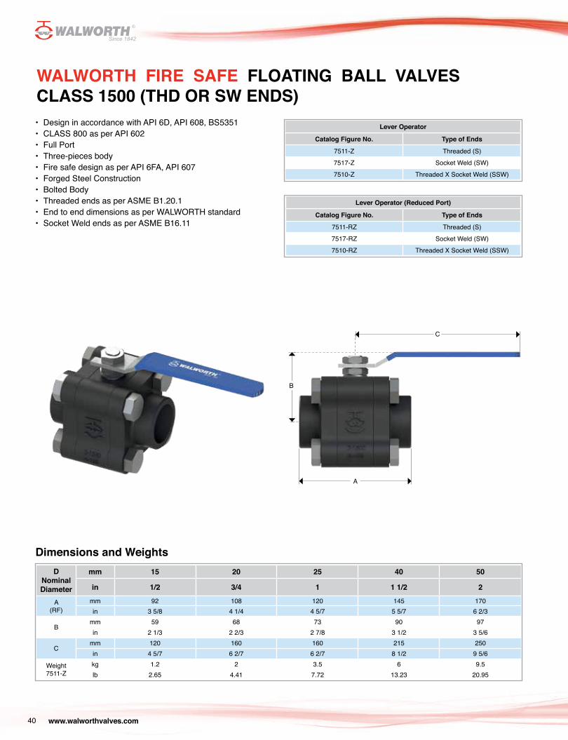
• Design in accordance with API 6D, API 608, BS5351• CLASS 800 as per API 602• Full Port• Three-pieces body• Fire safe design as per API 6FA, API 607• Forged Steel Construction• Bolted Body• Threaded ends as per ASME B1.20.1• End to end dimensions as per WALWORTH standard• Socket Weld ends as per ASME B16.11
WALWORTH FIRE SAFE FLOATING BALL VALVES CLASS 1500 (THD OR SW ENDS)
Lever Operator
Catalog Figure No. Type of Ends
7511-Z Threaded (S)7517-Z Socket Weld (SW)7510-Z Threaded X Socket Weld (SSW)
Lever Operator (Reduced Port)
Catalog Figure No. Type of Ends
7511-RZ Threaded (S)7517-RZ Socket Weld (SW)7510-RZ Threaded X Socket Weld (SSW)
Dimensions and WeightsD
Nominal Diameter
mm 15 20 25 40 50
in 1/2 3/4 1 1 1/2 2
A(RF)
mm 92 108 120 145 170in 3 5/8 4 1/4 4 5/7 5 5/7 6 2/3
Bmm 59 68 73 90 97in 2 1/3 2 2/3 2 7/8 3 1/2 3 5/6
Cmm 120 160 160 215 250in 4 5/7 6 2/7 6 2/7 8 1/2 9 5/6
Weight7511-Z
kg 1.2 2 3.5 6 9.5lb 2.65 4.41 7.72 13.23 20.95
C
B
A
www.walworthvalves.com 41
• Design in accordance with API 6D, API 608, BS5351• CLASS 2500 as per ASME B16.34• Full Port• Three-pieces body• Fire safe design as per API 6FA, API 607• Forged Steel Construction• Bolted Body• Threaded ends as per ASME B1.20.1• End to end dimensions as per WALWORTH standard• Socket Weld ends as per ASME B16.11
WALWORTH FIRE SAFE FLOATING BALL VALVES CLASS 2500 (THD OR SW ENDS)
Lever Operator
Catalog Figure No. Type of Ends
7211-Z Threaded (S)7217-Z Socket Weld (SW)7210-Z Threaded X Socket Weld (SSW)
Lever Operator (Reduced Port)
Catalog Figure No. Type of Ends
7211-RZ Threaded (S)7217-RZ Socket Weld (SW)7210-RZ Threaded X Socket Weld (SSW)
Dimensions and WeightsD
Nominal Diameter
mm 15 20 25 40
in 1/2 3/4 1 1 1/2
A(RF)
mm 170 190 205 260in 6 2/3 7 1/2 8 10 1/4
Bmm 62 75 80 111in 2 4/9 3 3 1/7 4 3/8
Cmm 220 250 250 400in 8 2/3 9 5/6 9 5/6 15 3/4
Weight7211-Z
kg 2.8 4.5 7 15lb 6.17 9.92 15.44 33.08
C
B
A

www.walworthvalves.com42
Locking DeviceValves are designed with locking devices, just to put a lock in the lockholes to prevent misoperation in the fully opened or closed position of people not authorized to use them, specially when the valves are mounted outdoors or when the valves are not allowed to be opened or closed by technical process. This locking device is designed for standard lock usage, valves are not supplied with the lock.
The following graph shows the soft seals service performance curves at different temperatures and pressures as a reference.
Flange ISO 5211This flange connection could be provided in the top of the valve to install an operator device by removing the lever.
ACCESSORIES FOR OPERATION
TOP VIEW FRONT VIEW
Stem
Limit Screws
Stop Plate with 90º Switch
Lockhole
Stem
Flange ISO 5211
PRESSURE-TEMPERATURE GRAPH FOR SOFT SEALSPRESSURE-TEMPERATURE RATINGS
100 200 300 400 500
2000
4000
6000
8000
10000
12000
Temperature (ºF)
Pres
sure
(psi
)
PTFE
RPTFE
Molon
Devlon
Peek
Nylon

www.walworthvalves.com 43
Temperature Working class pressure°F °C 150 300 600 800 1500 2500
- 20 to 100 -29 to 38 275 720 1440 1920 3600 6000
200 93 230 600 1200 1600 3000 5000
300 149 205 540 1075 1435 2690 4480
400 204 190 495 995 1325 2485 4140
500 260 170 465 9320 1240 2330 3880
600 316 140 440 885 1180 2210 3680
650 343 125 430 865 1150 2160 3600
700 371 110 420 845 1125 2110 3520
750 399 95 415 825 1100 2065 3440
800 427 80 405 710 1080 2030 3380
850 454 65 395 790 1055 1980 3300
900 482 50 390 780 1035 1945 3240
950 510 35 380 765 1020 1910 3180
1000 538 20 355 710 945 1770 2950
1050 566 20(*) 325 650 865 1630 2715
1100 593 20(*) 255 515 685 1285 2145
1150 621 20(*) 205 410 545 1030 1715
1200 649 20(*) 165 330 440 825 1370
1250 677 20(*) 135 265 355 970 1115
1300 704 20(*) 115 225 300 565 945
1350 732 20(*) 95 185 250 465 770
1400 760 20(*) 75 150 200 380 630
1450 788 20(*) 60 115 155 290 485
1500 816 15(*) 40 85 110 205 345
FORGED STAINLESS STEEL ASTM A182 Gr. F304(1) & ASTM A351 Gr. CF8(1)
(1) At temperatures over 1,000°F, use only when the carbon content is 0.04% or higher.(*) Flanged end valve ratings terminate at 1,000°F
Temperature Working class pressure°F °C 150 300 600 800 1500 2500
- 20 to 100 -29 to 38 285 740 1480 1975 3705 6170
200 93 260 680 1360 1810 3395 5655
300 149 230 655 1310 1745 3270 5450
400 204 200 635 1265 1690 3170 5280
500 260 170 605 1205 1610 3015 5025
600 316 140 570 1135 1515 2840 4730
650 343 125 550 1100 1465 2745 4575
700 371 110 530 1060 1415 2665 4425
750 399 98 505 1015 1350 2535 4230
800 427 80 410 825 1100 2055 3430
850 454 65 320 640 850 1595 2655
900 482 50 230 460 615 1150 1915
950 510 35 135 275 365 685 1145
1000 538 20 85 170 225 430 715
FORGED CARBON STEEL ASTM A105(1)(2),ASTM A182 Gr. LF2(1) & CAST STEEL A216 Gr. WCB(1)
PRESSURE-TEMPERATURE RATINGS
(1) Upon prolonged exposure to temperatures above 800°F.(2) Only killed steel shall be used above 850°F.

www.walworthvalves.com44
Temperature Working class pressure°F °C 150 300 600 800 1500 2500
- 20 to 100 -29 to 38 275 720 1440 1920 3600 6000
200 93 235 620 1240 1655 3095 5160
300 149 215 560 1120 1495 2795 4660
400 204 195 515 1025 1370 2570 4280
500 260 170 480 955 1275 2390 3980
600 316 140 450 900 1205 2255 3760
650 343 125 440 885 1180 2210 3680
700 371 110 435 870 1160 2170 3620
750 399 95 425 855 1140 2135 3560
800 427 80 420 745 1125 2110 3520
850 454 65 420 735 1115 2090 3480
900 482 50 415 730 1105 2075 3460
950 510 35 385 775 1030 1930 3220
1000 538 20 365 725 970 1820 3030
1050 566 20 360 720 960 1800 3000
1100 593 20(*) 305 610 815 1525 2545
1150 621 20(*) 235 475 630 1185 1970
1200 649 20(*) 185 370 495 925 1545
1250 677 20(*) 145 295 390 735 1230
1300 704 20(*) 115 235 310 585 970
1350 732 20(*) 95 190 255 480 800
1400 760 20(*) 75 150 200 380 630
1450 788 20(*) 60 115 155 290 475
1500 816 15(*) 40 85 110 205 345
FORGED STAINLESS STEEL ASTM A182 Gr. F316(1) & ASTM A351 Gr. CF8M(1)
(1) At temperatures over 1,000°F, use only when the carbon content is 0.04% or higher.(*) Flanged end valve ratings terminate at 1,000°F
Temperature Working class pressure°F °C 150 300 600 800 1500 2500
- 20 to 100 -29 to 38 290 750 1,500 2,000 3,750 6,250
200 93 260 750 1,500 2,000 3,750 6,250
300 149 230 730 1,455 1,940 3,640 6,070
400 204 200 705 1,405 1,875 3,520 5,865
500 260 170 665 1,330 1,775 3,325 5,540
600 316 140 605 1,210 1,615 3,025 5,040
650 343 125 590 1,175 1,570 2,940 4,905
700 371 110 555 1,110 1,480 2,775 4,630
750 399 95 505 1,015 1,350 2,535 4,230
800 427 80 410 825 1,100 2,055 3,430
850 454 65 320 640 850 1,595 2,655
900 482 50 225 445 595 1,115 1,855
950 510 35 135 275 365 685 1,145
1000 538 20 85 170 225 430 715
CAST LOW TEMPERATURE CARBON STEEL ASTM A350 Gr. LCC(1)
PRESSURE-TEMPERATURE RATINGS
(1) Not to be used over 650°F.
www.walworthvalves.com 45
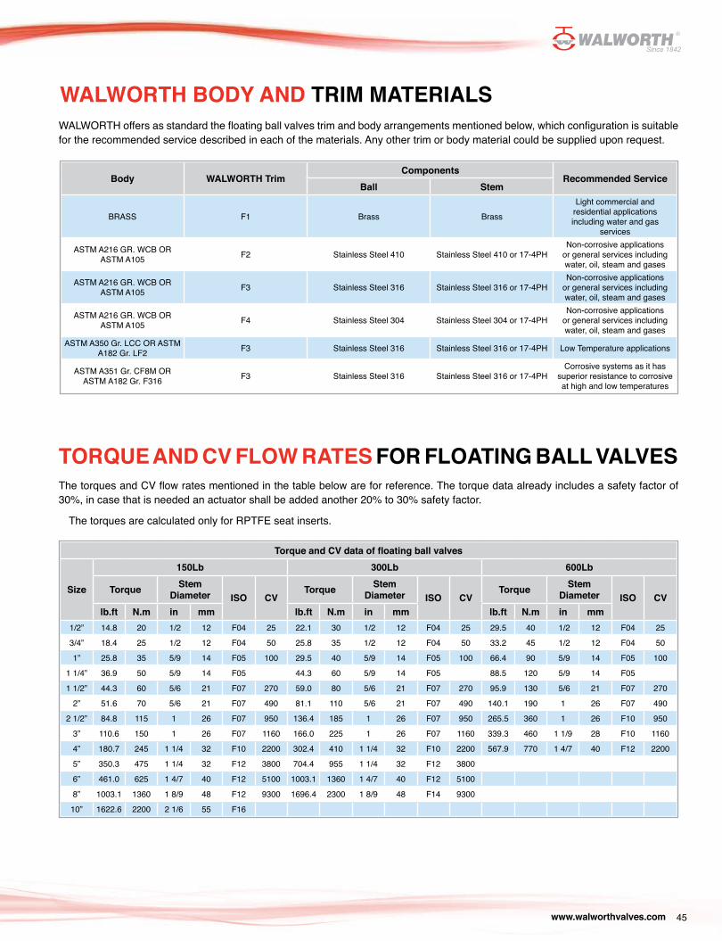
Torque and CV data of floating ball valves
Size
150Lb 300Lb 600Lb
Torque Stem Diameter ISO CV
Torque Stem Diameter ISO CV
Torque Stem Diameter ISO CV
lb.ft N.m in mm lb.ft N.m in mm lb.ft N.m in mm1/2” 14.8 20 1/2 12 F04 25 22.1 30 1/2 12 F04 25 29.5 40 1/2 12 F04 25
3/4” 18.4 25 1/2 12 F04 50 25.8 35 1/2 12 F04 50 33.2 45 1/2 12 F04 50
1” 25.8 35 5/9 14 F05 100 29.5 40 5/9 14 F05 100 66.4 90 5/9 14 F05 100
1 1/4” 36.9 50 5/9 14 F05 44.3 60 5/9 14 F05 88.5 120 5/9 14 F05
1 1/2” 44.3 60 5/6 21 F07 270 59.0 80 5/6 21 F07 270 95.9 130 5/6 21 F07 270
2” 51.6 70 5/6 21 F07 490 81.1 110 5/6 21 F07 490 140.1 190 1 26 F07 490
2 1/2” 84.8 115 1 26 F07 950 136.4 185 1 26 F07 950 265.5 360 1 26 F10 950
3” 110.6 150 1 26 F07 1160 166.0 225 1 26 F07 1160 339.3 460 1 1/9 28 F10 1160
4” 180.7 245 1 1/4 32 F10 2200 302.4 410 1 1/4 32 F10 2200 567.9 770 1 4/7 40 F12 2200
5” 350.3 475 1 1/4 32 F12 3800 704.4 955 1 1/4 32 F12 3800
6” 461.0 625 1 4/7 40 F12 5100 1003.1 1360 1 4/7 40 F12 5100
8” 1003.1 1360 1 8/9 48 F12 9300 1696.4 2300 1 8/9 48 F14 9300
10” 1622.6 2200 2 1/6 55 F16
Body WALWORTH TrimComponents
Recommended ServiceBall Stem
BRASS F1 Brass Brass
Light commercial and residential applications including water and gas
services
ASTM A216 GR. WCB OR ASTM A105 F2 Stainless Steel 410 Stainless Steel 410 or 17-4PH
Non-corrosive applications or general services including water, oil, steam and gases
ASTM A216 GR. WCB OR ASTM A105 F3 Stainless Steel 316 Stainless Steel 316 or 17-4PH
Non-corrosive applications or general services including water, oil, steam and gases
ASTM A216 GR. WCB OR ASTM A105 F4 Stainless Steel 304 Stainless Steel 304 or 17-4PH
Non-corrosive applications or general services including water, oil, steam and gases
ASTM A350 Gr. LCC OR ASTM A182 Gr. LF2 F3 Stainless Steel 316 Stainless Steel 316 or 17-4PH Low Temperature applications
ASTM A351 Gr. CF8M OR ASTM A182 Gr. F316 F3 Stainless Steel 316 Stainless Steel 316 or 17-4PH
Corrosive systems as it has superior resistance to corrosive at high and low temperatures
WALWORTH BODY AND TRIM MATERIALS
TORQUE AND CV FLOW RATES FOR FLOATING BALL VALVESThe torques and CV flow rates mentioned in the table below are for reference. The torque data already includes a safety factor of 30%, in case that is needed an actuator shall be added another 20% to 30% safety factor.
The torques are calculated only for RPTFE seat inserts.
WALWORTH offers as standard the floating ball valves trim and body arrangements mentioned below, which configuration is suitable for the recommended service described in each of the materials. Any other trim or body material could be supplied upon request.
www.walworthvalves.com46
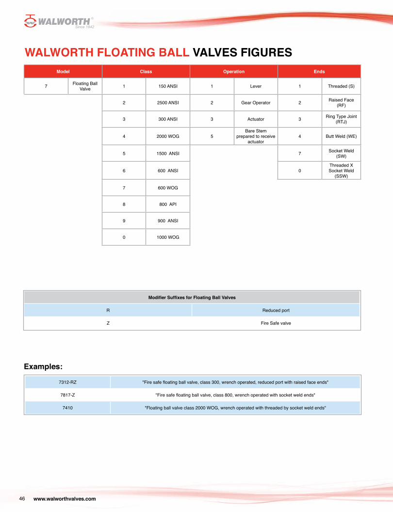
WALWORTH FLOATING BALL VALVES FIGURES
Modifier Suffixes for Floating Ball Valves
R Reduced port
Z Fire Safe valve
7312-RZ "Fire safe floating ball valve, class 300, wrench operated, reduced port with raised face ends"
7817-Z "Fire safe floating ball valve, class 800, wrench operated with socket weld ends"
7410 "Floating ball valve class 2000 WOG, wrench operated with threaded by socket weld ends"
Examples:
Model Class Operation Ends
7 Floating Ball Valve 1 150 ANSI 1 Lever 1 Threaded (S)
2 2500 ANSI 2 Gear Operator 2 Raised Face (RF)
3 300 ANSI 3 Actuator 3 Ring Type Joint (RTJ)
4 2000 WOG 5Bare Stem
prepared to receive actuator
4 Butt Weld (WE)
5 1500 ANSI 7 Socket Weld (SW)
6 600 ANSI 0Threaded X Socket Weld
(SSW)
7 600 WOG
8 800 API
9 900 ANSI
0 1000 WOG
www.walworthvalves.com 47
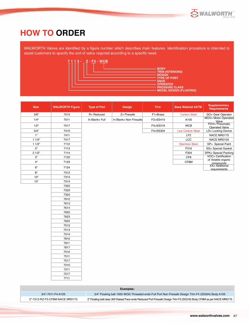
Size WALWORTH Figure Type of Port Design Trim Base Material ASTM Supplementary Requirements
3/8" 7010 R= Reduced Z= Firesafe F1=Brass Carbon Steel GO= Gear Operator
1/4" 7011 In Blank= Full In Blank= Non Firesafe F2=SS410 A105 MOV= Motor Operated Valve
1/2" 7017 F3=SS316 WCB POV= Pneumatic Operated Valve
3/4" 7410 F4=SS304 Low Carbon Steel LD= Locking Device1" 7411 LF2 NACE MR0175
1 1/4" 7417 LCC NACE MR01031 1/2" 7112 Stainless Steel SP= Special Paint
2" 7113 F316 SG= Special Gasket2 1/2" 7114 F304 SPK= Special Packing
3" 7122 CF8 VOC= Certification of Volatile organic
compounds4" 7123 CF8M
6" 7124 XX= Additional requirements
8" 731210" 731312" 7314
7322732373247612761376147622762376247512751375147810781178177510751175177210721172177711
HOW TO ORDER
Examples:
3/4”-7011-F4-A105 3/4” Floating ball 1000 WOG Threaded ends Full Port Non Firesafe Design Trim F4 (SS304) Body A1052”-7312-RZ-F3-CF8M-NACE MR0175 2” Floating ball class 300 Raised Face ends Reduced Port Firesafe Design Trim F3 (SS316) Body CF8M as per NACE MR0175
7 1 1 2 - Z - F3 - WCB
BODYTRIM (INTERIORS)DESIGNTYPE OF PORTENDSOPERATORPRESSURE CLASSMODEL DESIGN (FLOATING)
WALWORTH Valves are identified by a figure number which describes main features. Identification procedure is intended to assist customers to specify the sort of valve required according to a specific need.
www.walworthvalves.com48
DESIGN BASISAll of WALWORTH’s Valve Designs, when applicable, follow one or more of the following standards:
API American Petroleum Institute:API 598 Valve Inspection and TestingAPI 6D Pipeline Valves (Gate, Ball and Check) API 602 Pressure rating for class 800API 607 Fire Test for 1/4 Turn Soft-Seated Valves API 608 Metal Ball Valves-Flanged, Threaded and Welding ends
ANSI Standards National Standards Institute:ANSI B1.20.1 NPT General Purpose Pipe Threads (Inches) ANSI B16.5 Pipeline Flanges and Flanged Fittings ANSI B16.10 Face to Face and End to End Valve Dimensions ANSI B16.11 Socket Weld General Purpose DimensionsANSI B16.25 Butt Weld Ends
MSS Standards Manufacturer’s Standardization SocietyMSS SP-25 Standard Marking System for Valves, Fittings, Flanges and Unions MSS SP-55 Quality Standard for Steel Castings for Valves, Flanges, Fittings and Other Piping Components/Visual Method for Evaluation of Surface Irregularities MSS SP-72 Ball Valves with Flanged or Butt-Welding Ends for General Service
ASTM Standars American Society for Testing and Materials:ASTM A-105 Standard Specification for Carbon Steel Forgings for Piping Applications ASTM A-182 Standard Specification for Forged or Rolled Alloy Steel Pipe Flanges, Forged Fittings and Valves and Parts for High Temperature Service ASTM A-193 Standard Specification for Alloy Steel and Stainless Steel Bolting Materials for High Temperature Service ASTM A-194 Standard Specification for Carbon and Alloy Steel Nuts for High Pressure and High Temperature Service ASTM A-216 Standard Specification for Carbon Steel Castings, Suitable for Fusion Welding and High Temperature Service ASTM A-276 Standard Specification for Stainless and Heat-Resisting Steel Bars and Shapes ASTM A-320 Standard Specification for Alloy Steel Bolting Materials for Low Temperature Service ASTM A-350 Standard Specification for Carbon and Low Alloy Steel Forgings, Requiring Notch Toughness Testing for Piping Components ASTM A-351 Standard Specification for Steel Austenitic and Austenitic-Ferritic (Duplex) Castings for Pressure Containing Parts ASTM A-352 Standard Specification for Steel, Ferritic and Martensitic Castings for Pressure Containing Parts, Suitable for Low Temperature Service ASTM A-515 Standard Specification for Carbon Steel Pressure Vessel Plates for Intermediate and High Temperature Service ASTM A-564 Standard Specification for Hot-Rolled and Cold-Finished Age-Hardening Stainless Steel Bars and ShapesASTM B-124 Standard Specification for Copper and Copper Alloy Forging Rod, Bar, and ShapesASTM B-283 Standard Specification for Copper and Copper-Alloy Die Forgings (Hot-Pressed)
NACE Standard National Association of Corrosion Engineers NACE MR0175 Sulfide Stress Corrosion Cracking Resistant Metallic Materials for Oil Field Equipment
www.walworthvalves.com 49
DESIGN BASISASME Code American Society of Mechanical Engineers
ANSI/ASME B16.34 Valves—Flanged, Threaded, and Welding End (Pressure-temperature ratings)ANSI/ASME B31.1 Power Piping ANSI/ASME B31.2 Fuel Gas Piping ASME/ANSI B31.3 Process Piping
BS Code British Standard InstitutionBS 5351 Specification for steel ball valves for the petroleum, petrochemical and allied industries
Boiler and Pressure Vessel Code: Section II Part A - Ferrous Material Specifications Section II Part B - Non - Ferrous Material Specifications Section II Part C - Specifications for Welding Rods, Electrodes and Filler Metals Section V Non - Destructive Examination Section VIII Rules for Construction of Pressure Vessels, Divisions 1 and 2 Section IX Welding and Brazing Qualifications of Surface Irregularities
www.walworthvalves.com50
THE WALWORTH COMPANY GENERAL TERMS AND CONDITIONS
ACCEPTANCE: All quotations are for acceptance within 30 days from date of quotation unless extended in writing. In the event a purchase order is placed after this period of time. The WALWORTH Company reserves the right to requote base prices of all valves offered. All orders and contracts are subject to credit approval and acceptance by the WALWORTH Company.
FREIGHT: When prices are FOB point of shipment –no freight allowance, we will attempt to route shipments in the method which will result in the lowest cost unless otherwise instructed. All shipments will be freight charges collect except when stipulated on the purchase order, in which case you will be invoiced for all transportation charges. Delivery of material to a common carrier shall be considered to be delivery to Buyer and shall be at Buyer’s risk thereafter. Claims of loss of or damage to material in transit shall be filed by the Buyer directly with the carrier.
PRICES: There will be added to all prices quoted sales, use, occupation or any other excise or similar tax which Seller may be required to pay or collect on or in connection with the sale. Seller shall be established by Federal, State or other government regulation with respect to the product(s) covered by the order which shall be lower than the price(s) specified in the order.
ESCALATION TERMS: Prices shown in this price schedule reflect the costs in effect at the time of publication. These prices will remain firm on all products with a quoted delivery of twenty–six (26) weeks or less. On products which have a scheduled delivery of more than twenty-six (26) weeks, the goods will be invoiced based on the applicable price sheet in effect at the time of shipment. In no event will the invoiced price be less than the price originally quoted.
PURCHASED COMPONENTS: (i.e. motors, gearing, etc.) Prices are quoted on supplier price in effect at time of quotation. Actual invoice Price will be adjusted in accordance with the supplier’s escalation policy.
DEFERRED SHIPMENTS: If for any reason the customer desires to delay shipments more than 30 days after manufacturing is complete or to place a hold or stop to the order during the manufacturing cycle, The WALWORTH Company reserves the right to consider the order cancelled and to invoke cancellation charges per the schedule bellow.
CANCELLATION: After order acceptance by WALWORTH, items or completed orders may be cancelled and buyer will be charged for work performed, based on the following schedule:
- Five (5%) percent of prices of stock items.- Ten (10%) percent of price of stock items ordered in quantities which exceednormal inventory levels.- Five (5%) percent of prices prior to drawing submittal on made-to-order items.- 15% after drawing approval, but prior to the start of castings.- 30% to 50% during casting cycle, depending on the state of completion.- 55% to 75% during machining and assembly operations, depending on thestate of completion.-100% after final assembly and test.
REMITTANCES: Remittances must be made to the address indicated on theinvoice.
CREDIT TERMS: As quoted. Invoices on balances overdure will be subject to a service charge of 11/2 % per month on such indebtedness.
DELIVERIES: Shipments and deliveries shall at all times be subject to the approval of Seller’s Credit Department. If the Buyer shall fail to make any payments according to the terms of the contract, Seller may, in addition to and not in limitation of its other rights and remedies, at its option, cancel all or any part of Buyer’s incomplete contracts with Seller or may defer shipments of deliveries under Buyer’s contracts with Seller except upon receipt of satisfactory security or for cash shipment.All schedule of shipments are estimated as closely as possible and Seller will use its best efforts to ship within the time scheduled, but does not guarantee to do so. Schedules commence with the date Seller receives authorization to proceed with order, subject to the provisions of the next sentence. The order will not be released for manufacture until complete specifications and approved drawings (if drawing approval is required) are received at the plant of manufacture and the estimated schedule of shipment will commence with the date of such receipt.Seller shall not be liable for any direct, indirect or consequential damage or loss caused by any delay in delivery, regardless of the cause of delay.Without limiting the generality of the foregoing, Seller assumes no responsibility for delays in delivery resulting from fire, flood, accidents, riots, strikes, transportation delays, labor or material shortages, existing or future laws, acts of any governmental authority, or any other cause beyond Seller’s control. Items offered from stock are subject to prior sale.
INSPECTION: Final inspection and acceptance of products must be made at the plant of manufacture, unless otherwise provided in the order and/ or in agreed upon specifications. Prices do not include charges for special tests or inspections performed at the request of the Buyer, unless called for in the order and/or in agreed upon specifications.
RETURNS: Permission in writing and return tagging instructions must be obtained from Seller before any goods returned for credit or adjustment will be acceptance. Where returned goods are accepted, a minimum charge of 25% of the invoice price will be made, plus freight from both directions and costs of reconditioning the material for resale as new.
WARRANTY: Seller will replace without charge or refund the purchase price of products manufactured by Seller which prove to be defective in the material or workmanship , provided in each case that the product is properly installed and is used in the service for which Seller recommends it and that written claim, specifying the alleged defect, is presented to Seller shall in no event be responsible for (a) claims for labor, expenses or other damages occasioned by defective products or (b) for consequences or secondary damages. THE WARRANTY STATED IN THIS PARAGRAPH IS IN LIEU OF ALL OTHER WARRANTIES, EITHER EXPRESSED OR IMPLIED. WITH RESPECT TO WARRANTIES THIS PARAGRAPH STATES BUYER’S EXCLUSIVE REMEDY AND SELLER’S EXCLUSIVE LIABILITY.
DESIGN, ETC: Seller reserves the right to change design, materials or specifications without notice. There will be a charge for modifying an order after it has been entered when such change or modification results in additional engineering or clerical work for either The WALWORTH Company or our suppliers.
MINIMUM CHARGE: Orders totaling less than $100.00 USD net will be billed at a minimum charge of $100.00 USD. Repair parts will be billed at a minimum charge of $50.00 USD.
NOTE: We reserve the right to correct obvious clerical errors in quotations, invoices, and other contracts.

FLOATING BALL | 2012 EDITION | VERSION 1
www.walworthvalves.com
USA/CAN AUTHORIZED DISTRIBUTOR
TWC The Valve Company13641 Dublin Court, Stafford, Texas 77477 | Phone: (281) 566 1200 Fax: (281) 566 1299
www.twcvalves.com | e-mail: [email protected]
MÉXICO
Industrial de Válvulas, S.A. de C.V. Av. de la Industria Lote 16 Fracc. Industrial El Trébol, C.P. 54600 Tepotzotlán, Estado de México
Phone: (52 55) 5899 1700 Fax: (52 55) 5876 0156 | e-mail: [email protected]


