1
Ferritic stainless steels in structural applications
K.A. Cashell1 and N.R. Baddoo2 1 Department of Civil Engineering, Brunel University, UK 2 The Steel Construction Institute, Ascot, UK
Abstract
Ferritic stainless steels are low cost, price-stable, corrosion-resistant materials. Although widely used in the automotive and domestic appliance sectors, structural applications are scarce owing to a dearth of performance data and design guidance. The characteristics of ferritics make them appropriate for structures requiring strong and moderately durable structural elements with attractive metallic surface finishes. The present paper provides an overview of the structural behaviour of ferritic stainless steels, including a summary of the findings of a recent European project (SAFSS) on ferritics. Laboratory experiments have been completed including material tests as well as structural member tests, both at ambient and elevated temperature. The experimental data is supplemented by numerical analysis in order to study a wide range of parameters. The findings of this work have enabled design guidance to be proposed, as discussed herein.
1 Introduction
Stainless steel is the name given to a family of corrosion and heat resisting steels containing a minimum of 10.5% chromium. Whereas carbon steel needs to be painted with a protective coating if exposed to an outdoor environment, stainless steels have a naturally occurring corrosion resistant surface layer, known as the passive layer, which means that there is no requirement for applying protective surface layers. This invisible passive layer is primarily a consequence of the chromium content of the material.
The use of these materials in load-bearing structural applications has increased in recent years, mainly owing to their favourable strength, stiffness and durability characteristics as well the low maintenance requirements. Stainless steel can be fabricated using a wide range of commonly available engineering techniques, has a high recycled content and is fully recyclable at the end of its service life. It is often specified for structures in aggressive environments such as near deicing salts, water, or heavy pollution as well as in architectural applications. The main drawback is the relatively high initial cost compared with carbon steels although this is often offset over the lifetime of the structure owing to its low maintenance requirements and excellent durability [1].
There are many different grades of stainless steel meeting a wide range of strength, weldability and durability requirements, and these can be categorised into five groups: austenitic, ferritic, martensitic, duplex and precipitation-hardening grades. The austenitic and duplex grades are most commonly used in structural applications as they provide a good
2
combination of corrosion resistance, forming and fabrication properties and have been researched and validated. However, there is increased interest in ferritic stainless steels which share many of the attractive properties of austenitic and duplex materials such as strength and durability but are cheaper alloys containing little, or no, nickel. Used in the appropriate applications, ferritics can offer a very competitive and economical solution.
Despite being widely used in the automotive and domestic appliance sectors, structural applications of ferritic stainless steels are scarce owing to a lack of knowledge, performance data and design guidance. They have been specified for cladding and roofing applications as well as in the transportation sector for load-bearing members, for example for tubular bus frames. They have also been used for a range of structural applications in South Africa [2], including:
1. Structural steelwork for shaft supports in South African gold mines (these deep mines have very aggressive conditions, including high levels of chlorides and temperatures up to 50°C).
2. Railway electrification masts along the railway line in Port Elizabeth. The railway line runs along the coast and is constantly exposed to sea spray during windy conditions.
3. Tubular piles and support framework for the Marion Island Weather Station & Research Base, which is situated in a very corrosive environment on a volcanic island 1200 km south-east of Cape Town.
The Eurocode dealing with structural stainless steel, EN 1993-1-4 [3], states it is applicable to three traditional ferritic grades (1.4003, 1.4016 and 1.4512), however, the guidance is almost exclusively derived from work on austenitic and duplex stainless steels and in many cases ferritic-specific guidance is missing. Even taking into account experience using ferritics in other sectors, until recently there has been insufficient information available on structural performance, fire resistance, atmospheric corrosion resistance and strength of connections to give designers the confidence to specify these materials for structural applications.
It is in this context that a major collaborative project began in Europe in 2010 entitled Structural Applications of Ferritic Stainless Steels (hereafter referred to as SAFSS). The principal aim of the study was to develop the information needed for comprehensive structural design guidance to be included in relevant parts of the Eurocodes and other accompanying standards and guidance. It was also recognised that any limitations of these materials should be acknowledged. Although the research has general applicability to the use of ferritic stainless steel, there is a particular focus on light gauge steel framing, purlins, roof trusses and space-frames structures as well as steel decking for composite floors.
This paper presents a thorough description of ferritic stainless steels including the essential information that is required in order to specify these materials in structural applications. An overview and appraisal of recent research is also provided with the focus given to providing dedicated structural design guidance for the ferritic grades, which is in line with current Eurocode procedures.
3
2 Ferritic stainless steels
2.1 General
‘Ferritics’ are a family of utility stainless steels which offer significantly better atmospheric corrosion resistance than carbon steels, as well as having good ductility, formability and impact resistance. They have been used for a range of applications including vehicle frames/chassis, railway wagons, conveyors, chutes, tanks and walkways in industries such as road and rail transport, water, power generation and mining.
The initial material cost of stainless steel is largely controlled by the alloy content, in particular the level of nickel, which is around 8% - 10% for the common austenitic grades. As ferritic stainless steels do not contain nickel, they are cheaper and relatively price-stable compared with the austenitic grades generally encountered in construction. The cost of austenitics is strongly dependent on the London Metal Exchange (LME) nickel price which is highly volatile and periodically shows dramatic increases (e.g. between 2005 and 2008) thereby distorting the market price for austenitics.
The mechanical and physical properties of ferritic stainless steels, which are described in the current paper, make them suitable for a number of structural applications, for example where strong and moderately durable structural elements with attractive metallic surface finishes are required. Unlike galvanised or painted steel, ferritic stainless steels have a naturally occurring corrosion resistant surface layer so there is no requirement for applying protective surface layers and no remedial work or corrosion risk at cut edges. Ferritic stainless steels can be produced in a range of dull and bright surfaces.
Ferritics generally have limited low-temperature toughness, particularly for thicker sections [4]. The ferritic grade 1.4003, however, has a modified microstructure which ensures adequate toughness for external structural applications (40J at -40°C), which is equivalent to structural carbon steel. Ferritics can be welded by conventional methods, though there can be a loss of ductility and toughness. Due to these limitations in low-temperature toughness and weldability, ferritics tend to be used in thicknesses less than 6 mm for thin-walled cold-formed sections (e.g. hollow sections, channels etc.).
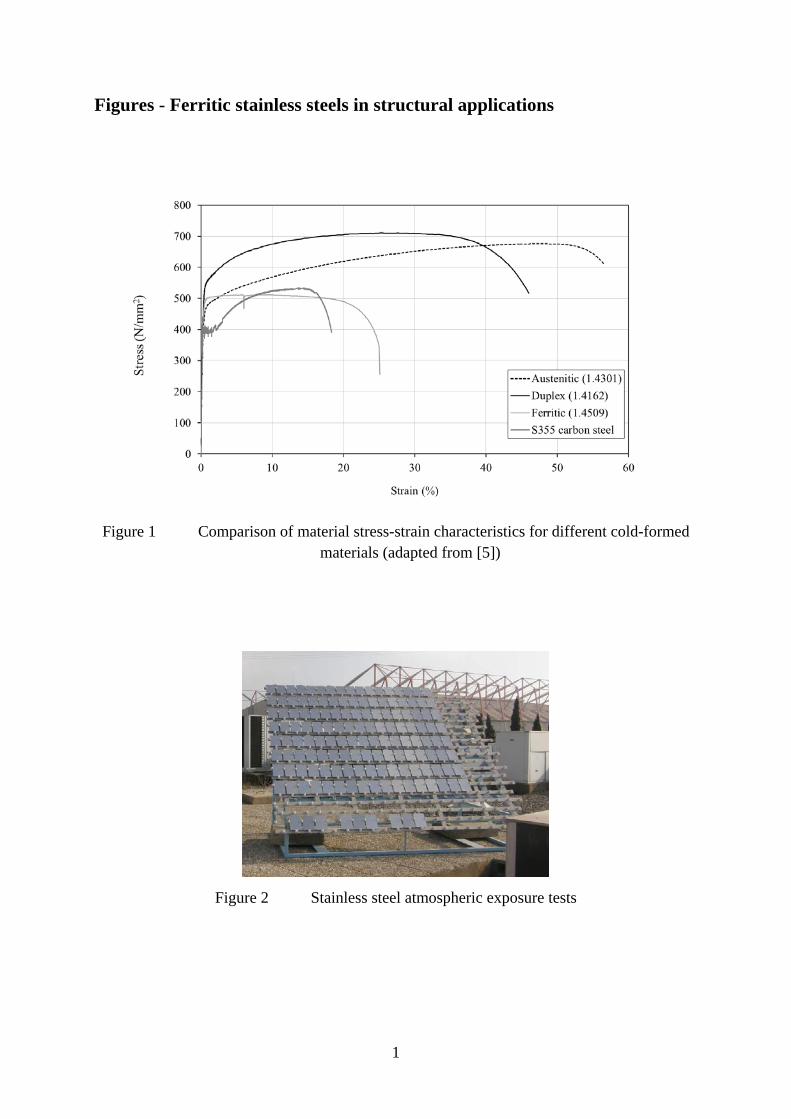
Figure 1 illustrates a comparison between the stress-strain responses for a typical ferritic grade with other materials.
2.2 International design standards
Three ferritic grades are covered in the American ASCE/SEI specification for design of cold-formed stainless steel structural members [6] for thicknesses up to 3.8 mm, namely grades 1.4512, 1.4016 and 1.4510. The South African (South African Bureau of Standards, 1997) [7] and Australian/New Zealand (Standards Australia Standards New Zealand, 2001) [8] structural stainless steel standards also include grade 1.4003.
The current version of the Eurocode for structural stainless steel, EN 1993-1-4 [3] states it is applicable to three ferritic grades (Grades 1.4003, 1.4016 and 1.4512), however, the guidance is almost exclusively derived from work on austenitic and duplex stainless steels and in many
4
cases ferritic-specific guidance is missing. EN 1993-1-4 refers to a number of clauses in other parts of Eurocode 3 such as EN 1993-1-2 [9], 1-8 [10], 1-9 [11] and 1-10 [12] which have not been validated for ferritic stainless steels. One exception is that EN 1993-1-2 includes data on one ferritic grade.
2.3 Grades
The actual corrosion resistance of a particular grade of stainless steel depends on its constituent elements, and hence each grade has a slightly different response when exposed to a corrosive environment. The most common reasons that a material may not perform as well as expected in terms of corrosion resistance are (i) that the local environment was incorrectly assessed, or (ii) the way in which the stainless steel has been worked or treated may introduce a state not envisaged in the initial assessment [13]. Accordingly, care is needed to select the most appropriate grade of stainless steel for a given application. Generally, the higher the level of corrosion resistance required, the greater the cost of the material.
There are hundreds of grades of stainless steel, including ferritics, which cover a wide range of strength and durability requirements. However, the sheer number of grades available can be a significant cause of confusion for designers and a barrier to achieving economic solutions. Hence, it is recommended that structural design guidance for ferritics focuses on 5 grades with varying levels of corrosion resistance and cost, all of which are selected from the European material standard for stainless steels [14] and are readily available from producers.
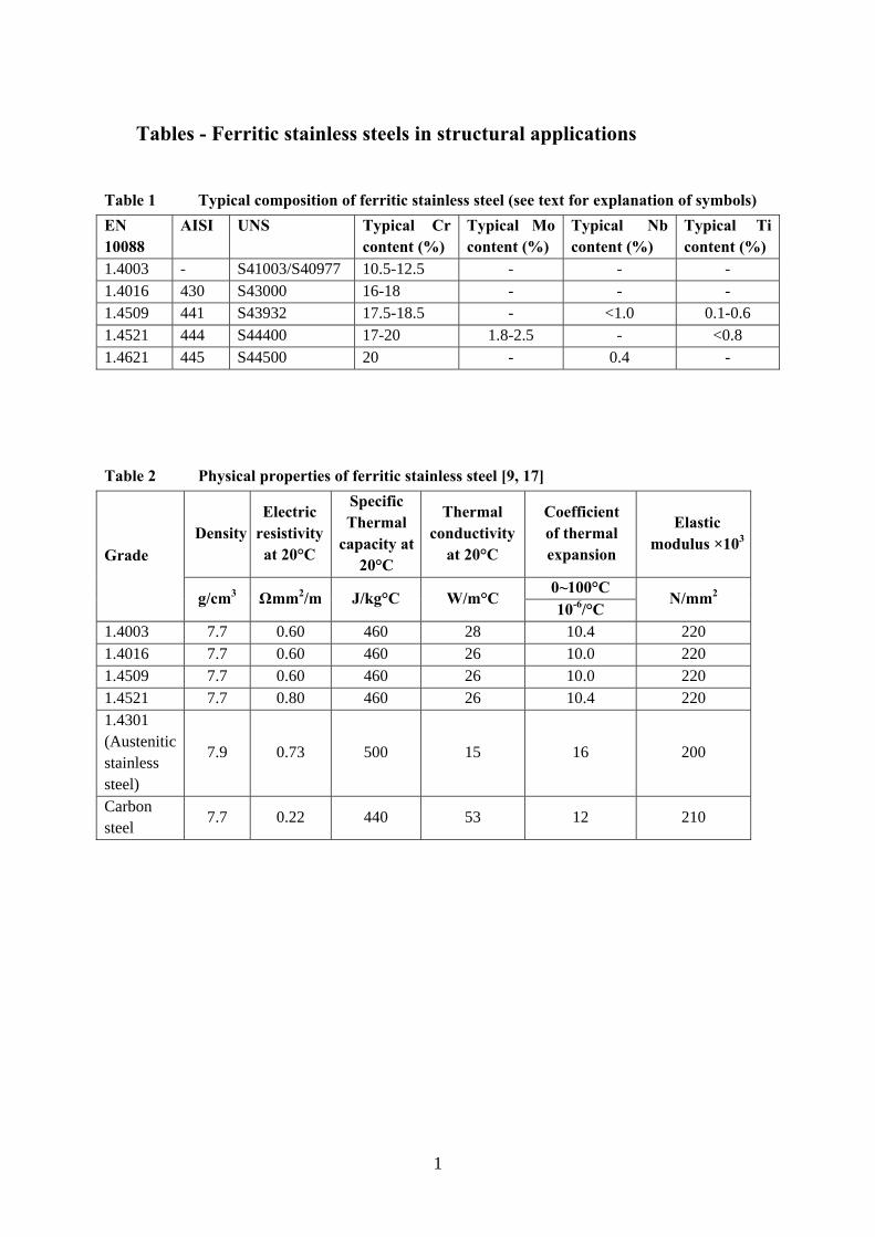
These grades are listed in Table 1 which gives the different international designations for each material. The AISI number refers to the number used by the American Iron and Steel Institute whereas the UNS (Unified numbering system) is used by ASTM International and SAE International. Hereafter, this paper will refer to materials by their European (i.e. EN 10088) grade number. Ferritic stainless steel is available in the form of sheet, strip or plate and can be used for structural sections such as channels and hollow sections.
Table 1 also presents the typical content of alloying elements such as chromium (Cr), molybdenum (Mo), niobium (Nb) and titanium (Ti). The values are taken from the European material standard [14], apart from the grade 1.4621 which is to be included in the next revision of EN 10088 Part 2 (due to be published later in 2014) [15]. Niobium and titanium are known as stabilising elements and are generally added to prevent the precipitation of chromium carbides following heat treatment and/or welding thus providing added resistance to intergranular corrosion and embrittlement. Molybdenum improves the corrosion resistance, especially against chloride-induced pitting [16].
2.4 Material selection
Stainless steel is normally selected in structural applications because of its corrosion resistance and/or its pleasing appearance and hence these are primary factors in choosing a suitable grade. The selection of the correct grade of ferritic stainless steel must take into account the environment of the application, the fabrication route, surface finish and the future maintenance of the structure. Hence, once the designer has chosen to use stainless steel, the next important step is usually to characterise the service environment, with special attention
5
paid to the possibility of highly localised conditions (e.g. proximity to chimneys venting corrosive fumes, etc.). Relative humidity, temperature, rain and wind are some of the parameters that can influence the behaviour of the material. Possible future developments or change of use should also be considered.
Grades 1.4003 and 1.4016 are the most commonly used ferritic alloys worldwide. Typical of ferritics, they have a lower work hardening rate than standard austenitic grades. Although relatively leanly alloyed, they both offer good corrosion resistance in an appropriate environment. These grades might be appropriate in cases where localised surface rust (pitting corrosion), for example, is acceptable (without a degradation in the mechanical properties).
The more alloyed grades 1.4509, 1.4521 and 1.4621 offer greater corrosion resistances and therefore are suitable for more aggressive environments. Grades 1.4509 and 1.4621 are broadly similar in terms of corrosion resistance to austenitic grade 1.4301 (304) and 1.4521 is similar to austenitic grade 1.4401 (316).
Once materials with satisfactory corrosion resistance are selected, consideration should then be given to mechanical properties, ease of fabrication, availability of product forms, surface finish and costs. In terms of weldability and formability, the grades containing the stabilising elements niobium and titanium perform best although all ferritics can be welded under the correct conditions, as discussed herein.
2.5 Material properties at ambient temperature
2.5.1 Durability
A comprehensive study into the durability of ferritic stainless steel in various atmospheric environments was undertaken as part of the SAFSS project [17]. Flat sheets with different surface finish, as well as both welded and bolted specimens, were investigated by exposing samples for up to 18 months in Seville, Isbergues, Ljubljana and Tornio (see Figure 2 for a typical exposure rack). The specimens were supplied by three different producers. The study also included laboratory corrosion tests (climatic accelerated tests and electrochemical tests) to further characterise the behaviour and enable design guidance to be proposed for structural applications.
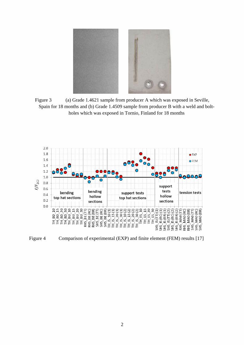
The main observation from the tests is that of the tested grades and environments, only grade 1.4003 developed significant surface corrosion. Generally, the grades performed as expected with the most alloyed materials (i.e. 1.4521 and 1.4621) performing the best. Some images of exposed samples are presented in Figure 3. The test results showed that ferritics may be used in a variety of external environments even though the less highly alloyed grades may tarnish or stain over time in an aggressive environment, this does not necessarily affect the structural integrity of the material.
Generally, although not examined in the SAFSS project, it is noteworthy that ferritic stainless steels have good resistance to chloride stress corrosion cracking [16]. However, due to the absence of nickel, they tend to offer less resistance to crevice corrosion than other families of stainless steel, although they still offer more resistance than carbon steels.
2.5.2 Physical properties
6
The physical properties of ferritic stainless steels are given in the European standard for stainless steel [18] and are presented in Table 2 together with those of carbon steel [9] and austenitic grade 1.4301 stainless steel [18], for comparison. Grade 1.4621 is not included in the table as it is not listed in the current version of the standard, but its physical properties are very similar to that of 1.4521. The ferritic grades are magnetic. They have noticeably higher values of thermal conductivity and so can transfer heat comparatively more efficiently than austenitic stainless steels. The thermal expansion coefficient for ferritic stainless steels is much lower than that of austenitic steel and is more similar to that of carbon steels. This causes ferritics to distort less than austenitics when heated.
2.5.3 Mechanical properties
The stress-strain behaviour of stainless steel differs from that of carbon steels in a number of respects. The most important difference is in the shape of the stress strain curve. Whereas carbon steel typically exhibits linear elastic behaviour up to the yield stress and a plateau before strain hardening is encountered, stainless steel has a more rounded response, with no well-defined yield stress (Figure 1). The response of ferritic stainless steel lies somewhere between that of carbon steel and austenitic stainless steel in that it is not quite as ‘rounded’ or nonlinear as the austenitic grades but offers more strength and ductility than carbon steel.
An extensive series of material tests were completed as part of the SAFSS project. Both tension and compression tests were carried out on the five ferritic stainless steel grades described previously with thicknesses ranging from 1.5 to 3.5 mm. The test materials were hot-rolled and cold-rolled sheets, and they were tested in the rolling direction as well as the transverse direction.
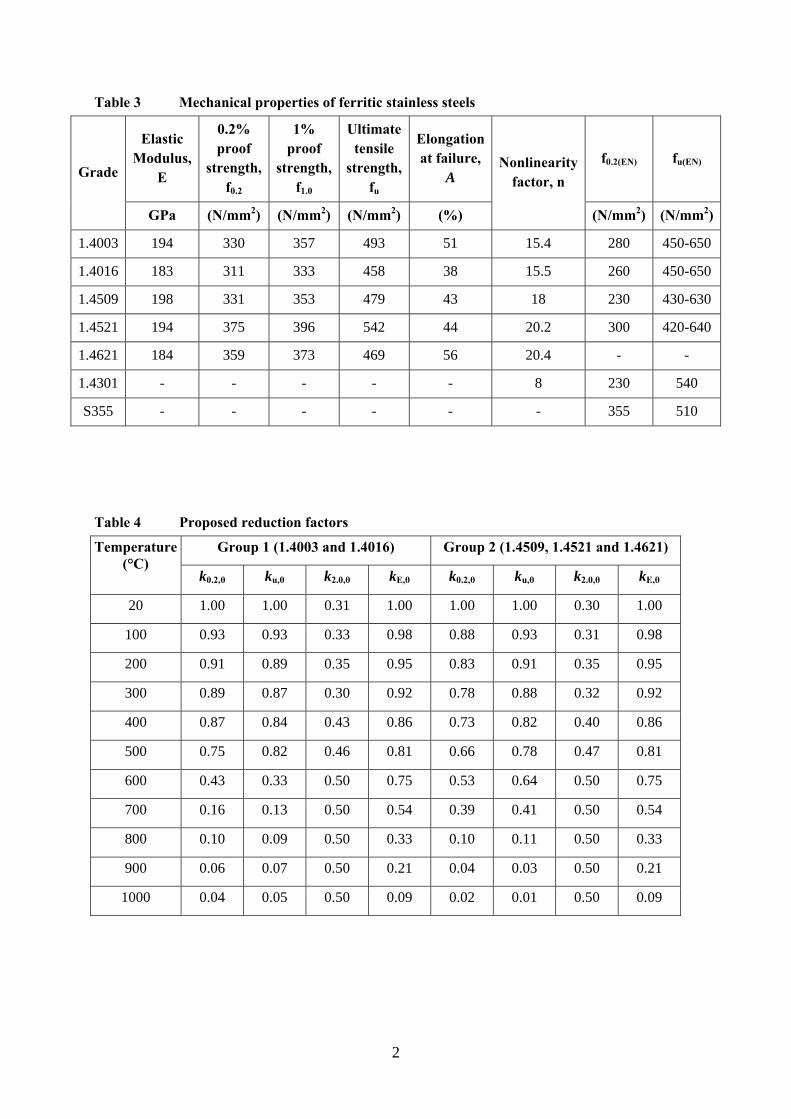
Table 3 presents the key material data measured during the tests, including the elastic modulus (E), the 0.2% and 1% proof strengths (f0.2 and f1.0, respectively), the ultimate tensile strength (fu), the elongation at failure (A) and the nonlinearity factor (n). Also included in the table are the 0.2% proof (f0.2(EN)) and ultimate (fu(EN)) strength values currently included in EN 10088-4 [14] for stainless steel and EN 10025-2 [19] for S275/S355 carbon steel. It is advisable that designers should use the values in EN 10088-4 for structural applications.
For brevity, all of the results shown are from samples tested in the longitudinal direction only. Tests in this direction usually give lower strength values than those in the transverse direction, which was also observed in these tests. The results in the table are the average for three tests on samples from the same producer. In some cases, tests were performed on the same grade of material from different producers and in these cases, only the lower values are presented in the table. All of the results in the table are from cold rolled material. A full report on the tests and results is available [17]. For structural design, the 0.2% proof strength is taken as the design strength.
Figure 1 illustrates that ferritic stainless steel exhibits some strain hardening after yielding but to a significantly lesser extent than is observed in other families of stainless steel. As shown in Table 3, all of the grades had significant over-strength and excess ductility with respect to the minimum requirements specified in EN1993-1-1 [20].
7
With reference to the elastic modulus, based on the results of these tests as well as a review of all other available data, it is recommended that a value of 200×103 N/mm2 is employed for structural design of ferritic grades, which is lower than the 220×103 N/mm2 value currently recommended in EN 10088-1 [18]. It is noteworthy that comparison of the tension and compression tests showed that ferritic stainless steels do not exhibit tension-compression anisotropy.
Also included in Table 3 are the measured nonlinear coefficients (n), which are used in material modelling to define the non-linearity of the stress-strain curve. This has been determined using the expression proposed by Real et al. [21], which is given in Eq. (1).
05.0
2.0ln
4ln
f
fn (1)
where f0.05 is the 0.05% proof strength.
2.6 Material properties at elevated temperature
The effect of elevated temperature on ferritic stainless steels has been established through a series of isothermal (steady state) and anisothermal (transient state) tests on ferritic grades. The results of these tests enabled the derivation of strength and stiffness reduction factors, for use in design. Based on the experimental observations, the grades were divided into two categories (groups 1 and 2) and reduction factors proposed for each group.
Group 1 contains the basic ferritic grades (i.e. 1.4003 and 1.4016) whereas group 2 is made up of the more alloyed stabilised grades, 1.4509, 1.4521 and 1.4621. The proposed reduction factors are presented in Table 4, where k0.2,θ, ku,θ, k2.0,θ and kE,θ are the reduction factors for the 0.2% proof strength, ultimate strength, 2% proof strength and Young’s modulus, respectively, determined at each temperature by normalising the value by their corresponding value in ambient conditions.
3 Structural response of ferritic stainless steel members
Until recently there was very little information on the structural response of ferritic stainless steel members available in the literature. A primary aim of the SAFFS project was to produce sufficient data to enable design guidance to be recommended in line with current Eurocode procedures. In this context, a detailed experimental and numerical study was completed within four main categories:
1. Ferritic stainless members with open and hollow cross-sections. 2. Composite floors with ferritic stainless steel decking. 3. Elevated temperature response of ferritic elements. 4. Connections.
The following sub-sections describe the fundamental outcomes and design proposals recommended following this study. Although not discussed in the current paper for space reasons, the ferritic grades have been included in a detailed reliability study focussed on
8
assessing the Eurocode 3 partial resistance factors for stainless steel [22]. The aim of the paper is not to describe the experimental and numerical work in great detail (this information is available elsewhere [17]) but to focus on the design-orientated findings.
3.1 Structural performance of ferritic stainless steel members
A detailed numerical study using GMNIA (i.e. geometrically and materially non-linear analysis of the imperfect structure) was undertaken to analyse the behaviour of thin-walled ferritic stainless steel structural sections such as hollow and top-hat channels. These were verified through a series of experiments and the results were compared to current Eurocode provisions.
Over 40 tests were completed on cold-formed sections including bending tests, internal and external support tests as well as web-crippling tests. Both top-hat and rectangular hollow sections were examined. The experimental results were compared with the resistances given in the Eurocodes (EN 1993-1-3 [23], with modifications from EN 1993-1-4 [3] where appropriate) and it was determined that in bending, the Eurocode gives conservative results in all cases apart from for the most slender top-hat sections.
Following validation of the numerical model, which was programmed using Abaqus, a parametric study assessed the effect of material behaviour, enhanced properties in corners, initial imperfections and residual stresses on the response. The material model used in finite element simulations was based on the Mirambell-Real two stage material model [24] and the parameters were optimized from the stress-strain measurement of the material used for experiments. Figure 4 summarizes the analysis for the hollow and top-hat sections where it is seen that the load (both the experimental load and the load determined from the numerical analysis) has been normalised against the Eurocode 3 predicted values. In almost all cases the Eurocode gives a conservative prediction and it can also be seen that the finite element model gives a good description of the behaviour.
The experimental and numerical study enabled several recommendations to be made for the design of ferritic steel structures, in line with current Eurocode practices, as discussed in the following subsections. The study covered local buckling, flexural buckling about the major and minor axes, torsional-flexural buckling and lateral-torsional buckling of beams as well as web crippling. Several different material types were included in the analysis (e.g. variation in strength, stiffness, nonlinearity, ductility etc.).
3.1.1 Cross-section classification
It is recommended that the cross-section classification limits and reduction factors proposed in Gardner and Theofanous [25] are adopted in design guidance for ferritic stainless steel members. For consistency with carbon steel design rules, it is recommended that the outstand elements of channel sections are classified according to the current width-to-thickness definition in EN 1993-1-1 [20].
3.1.2 Overall buckling of compression members
Based on the numerical analysis, some changes to the buckling provisions in EN 1993-1-4 [3]
are recommended. Firstly, the analysis has indicated that the value for 0 initial slenderness
9
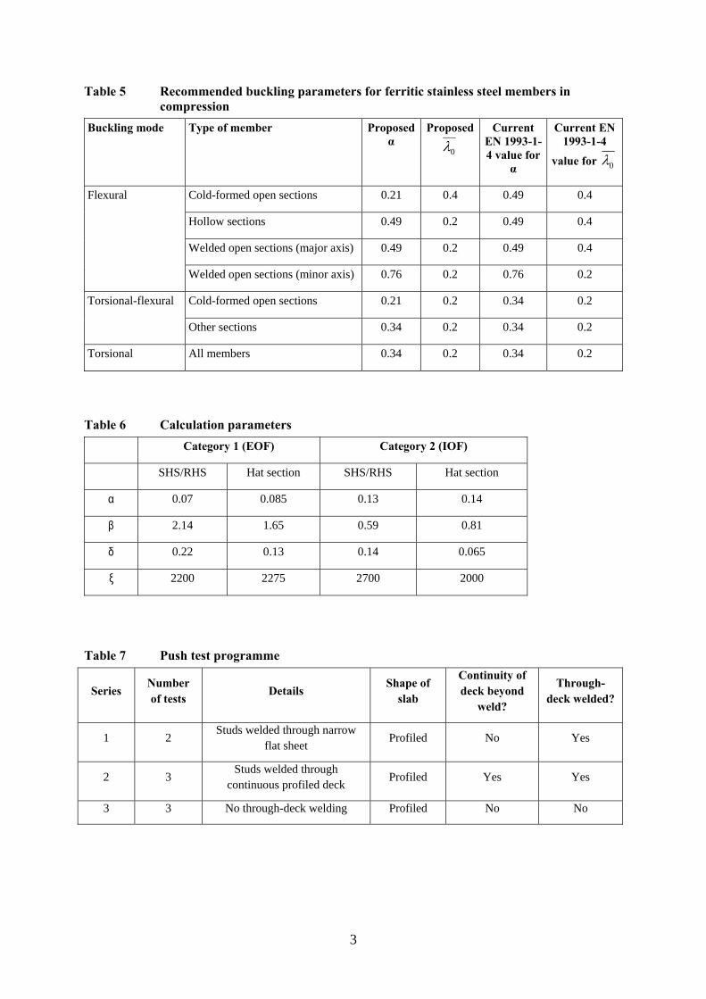
of hollow sections made from ferritic steels (where the ratio of ultimate to design strength fu/f0.2 is typically low) should be lower than the current value of 0.4. The proposed parameters are presented in Table 5, which also includes the current values in EN 1993-1-4 for comparison.
3.1.3 Web crippling
Web crippling is an important failure mode to consider in cold-formed steel design. The web crippling strength of cold-formed steel sections is a function of many variables such as section type, cross sectional parameters, bearing length and the loading conditions. The current version of EN 1993-1-4 [3] does not consider any stainless-specific rules for local transverse force verification when calculating the web crippling resistance of cold formed cross-sections, implying that the rules for carbon steel in EN 1993-1-3 can be applied (refer to the Design Manual section 5.4.4 [13]) However, the formula for sections with two or more unstiffened webs (Clause 6.1.7.3 in EN 1993-1-3 [23]) is only applicable for hat sections and sheeting, and does not explicitly include hollow sections. Although the design rules are often used by designers for hollow sections, there is no evidence of their applicability.
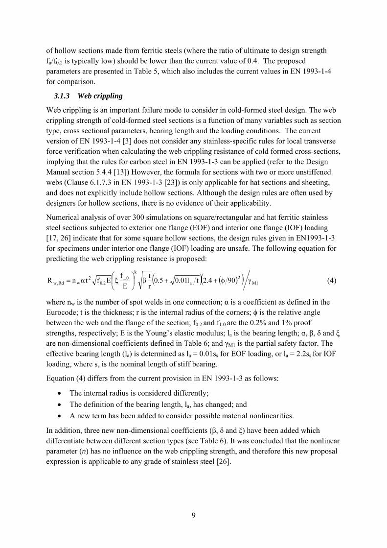
Numerical analysis of over 300 simulations on square/rectangular and hat ferritic stainless steel sections subjected to exterior one flange (EOF) and interior one flange (IOF) loading [17, 26] indicate that for some square hollow sections, the design rules given in EN1993-1-3 for specimens under interior one flange (IOF) loading are unsafe. The following equation for predicting the web crippling resistance is proposed:
1M2
a
k0.1
2.02
wRd,w 904.2tl01.05.0r
t
E
fEftnR
(4)
where nw is the number of spot welds in one connection; α is a coefficient as defined in the Eurocode; t is the thickness; r is the internal radius of the corners; ϕ is the relative angle between the web and the flange of the section; f0.2 and f1.0 are the 0.2% and 1% proof strengths, respectively; E is the Young’s elastic modulus; la is the bearing length; α, β, δ and ξ are non-dimensional coefficients defined in Table 6; and γM1 is the partial safety factor. The effective bearing length (la) is determined as la = 0.01ss for EOF loading, or la = 2.2ss for IOF loading, where ss is the nominal length of stiff bearing.
Equation (4) differs from the current provision in EN 1993-1-3 as follows:
The internal radius is considered differently;
The definition of the bearing length, la, has changed; and
A new term has been added to consider possible material nonlinearities.
In addition, three new non-dimensional coefficients (β, δ and ξ) have been added which differentiate between different section types (see Table 6). It was concluded that the nonlinear parameter (n) has no influence on the web crippling strength, and therefore this new proposal expression is applicable to any grade of stainless steel [26].
10
3.2 Structural performance of steel-concrete composite floor systems
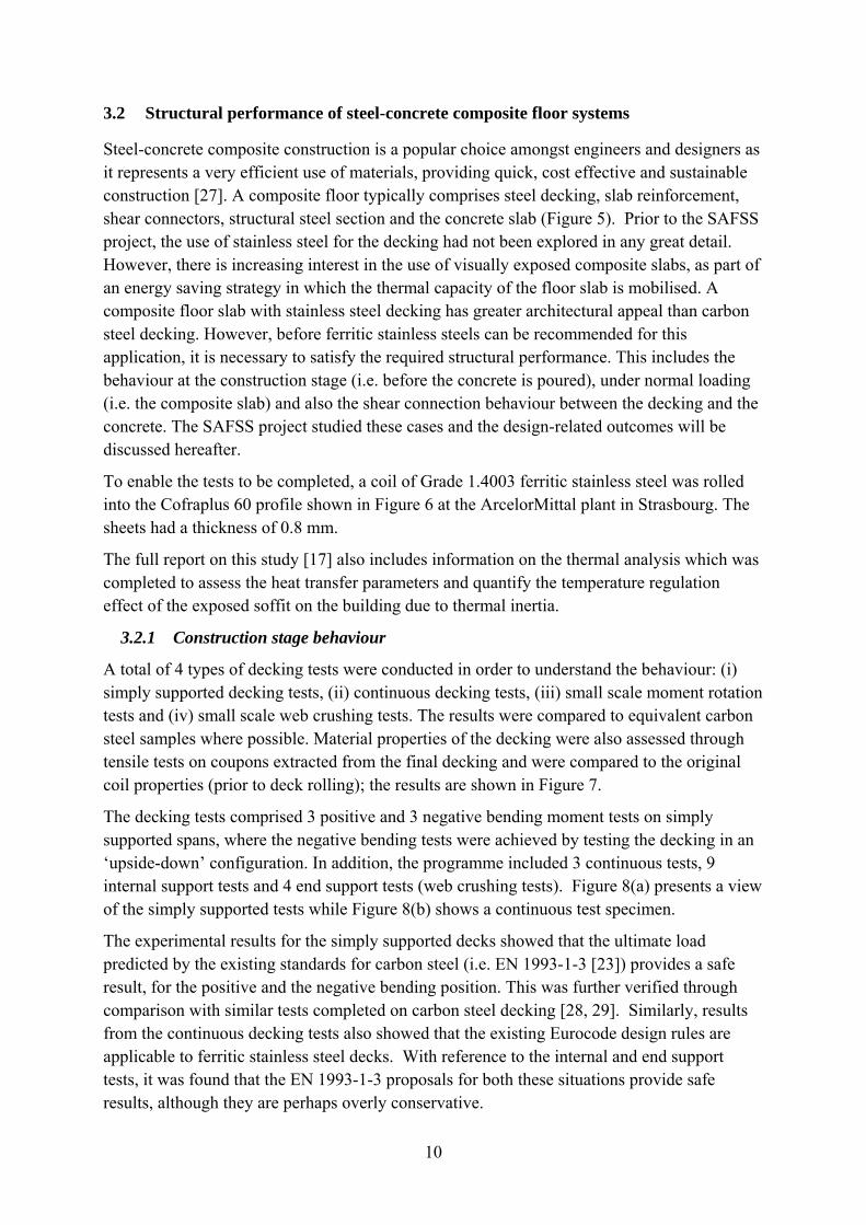
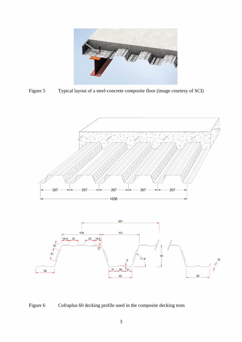
Steel-concrete composite construction is a popular choice amongst engineers and designers as it represents a very efficient use of materials, providing quick, cost effective and sustainable construction [27]. A composite floor typically comprises steel decking, slab reinforcement, shear connectors, structural steel section and the concrete slab (Figure 5). Prior to the SAFSS project, the use of stainless steel for the decking had not been explored in any great detail. However, there is increasing interest in the use of visually exposed composite slabs, as part of an energy saving strategy in which the thermal capacity of the floor slab is mobilised. A composite floor slab with stainless steel decking has greater architectural appeal than carbon steel decking. However, before ferritic stainless steels can be recommended for this application, it is necessary to satisfy the required structural performance. This includes the behaviour at the construction stage (i.e. before the concrete is poured), under normal loading (i.e. the composite slab) and also the shear connection behaviour between the decking and the concrete. The SAFSS project studied these cases and the design-related outcomes will be discussed hereafter.
To enable the tests to be completed, a coil of Grade 1.4003 ferritic stainless steel was rolled into the Cofraplus 60 profile shown in Figure 6 at the ArcelorMittal plant in Strasbourg. The sheets had a thickness of 0.8 mm.
The full report on this study [17] also includes information on the thermal analysis which was completed to assess the heat transfer parameters and quantify the temperature regulation effect of the exposed soffit on the building due to thermal inertia.
3.2.1 Construction stage behaviour
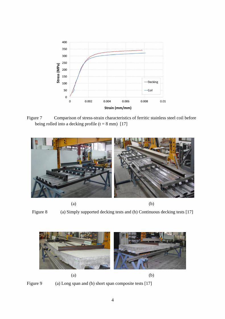
A total of 4 types of decking tests were conducted in order to understand the behaviour: (i) simply supported decking tests, (ii) continuous decking tests, (iii) small scale moment rotation tests and (iv) small scale web crushing tests. The results were compared to equivalent carbon steel samples where possible. Material properties of the decking were also assessed through tensile tests on coupons extracted from the final decking and were compared to the original coil properties (prior to deck rolling); the results are shown in Figure 7.
The decking tests comprised 3 positive and 3 negative bending moment tests on simply supported spans, where the negative bending tests were achieved by testing the decking in an ‘upside-down’ configuration. In addition, the programme included 3 continuous tests, 9 internal support tests and 4 end support tests (web crushing tests). Figure 8(a) presents a view of the simply supported tests while Figure 8(b) shows a continuous test specimen.
The experimental results for the simply supported decks showed that the ultimate load predicted by the existing standards for carbon steel (i.e. EN 1993-1-3 [23]) provides a safe result, for the positive and the negative bending position. This was further verified through comparison with similar tests completed on carbon steel decking [28, 29]. Similarly, results from the continuous decking tests also showed that the existing Eurocode design rules are applicable to ferritic stainless steel decks. With reference to the internal and end support tests, it was found that the EN 1993-1-3 proposals for both these situations provide safe results, although they are perhaps overly conservative.
11
3.2.2 Normal stage behaviour
A total of eight composite slab tests were conducted including four long span and four short span slabs, to investigate the response of composite slabs under normal service load. These included six tests using ferritic decking and two comprising galvanized steel (one long and one short) to enable a direct comparison to be made of the two steels. Figure 9 presents two images from the tests [17].
The Eurocode for carbon steel composite construction, EN 1994-1-1 [30], includes two design methods for composite slabs, namely the m-k method and the partial connection method. Both were used to analyse the tests and the results showed that the ultimate loads were very well predicted by both design methods. Furthermore, it was shown that the ultimate loads were very similar for the slabs regardless of whether ferritic or galvanised sheeting was used. This is an important conclusion for ferritic stainless steel decking as it illustrates that (i) the load-bearing capacity is at least as good as for galvanised sheeting and (ii) the existing design rules are valid.
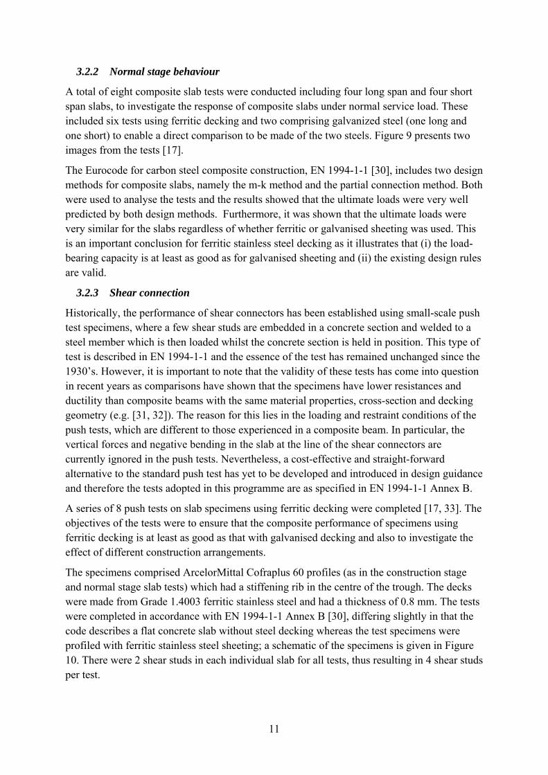
3.2.3 Shear connection
Historically, the performance of shear connectors has been established using small-scale push test specimens, where a few shear studs are embedded in a concrete section and welded to a steel member which is then loaded whilst the concrete section is held in position. This type of test is described in EN 1994-1-1 and the essence of the test has remained unchanged since the 1930’s. However, it is important to note that the validity of these tests has come into question in recent years as comparisons have shown that the specimens have lower resistances and ductility than composite beams with the same material properties, cross-section and decking geometry (e.g. [31, 32]). The reason for this lies in the loading and restraint conditions of the push tests, which are different to those experienced in a composite beam. In particular, the vertical forces and negative bending in the slab at the line of the shear connectors are currently ignored in the push tests. Nevertheless, a cost-effective and straight-forward alternative to the standard push test has yet to be developed and introduced in design guidance and therefore the tests adopted in this programme are as specified in EN 1994-1-1 Annex B.
A series of 8 push tests on slab specimens using ferritic decking were completed [17, 33]. The objectives of the tests were to ensure that the composite performance of specimens using ferritic decking is at least as good as that with galvanised decking and also to investigate the effect of different construction arrangements.
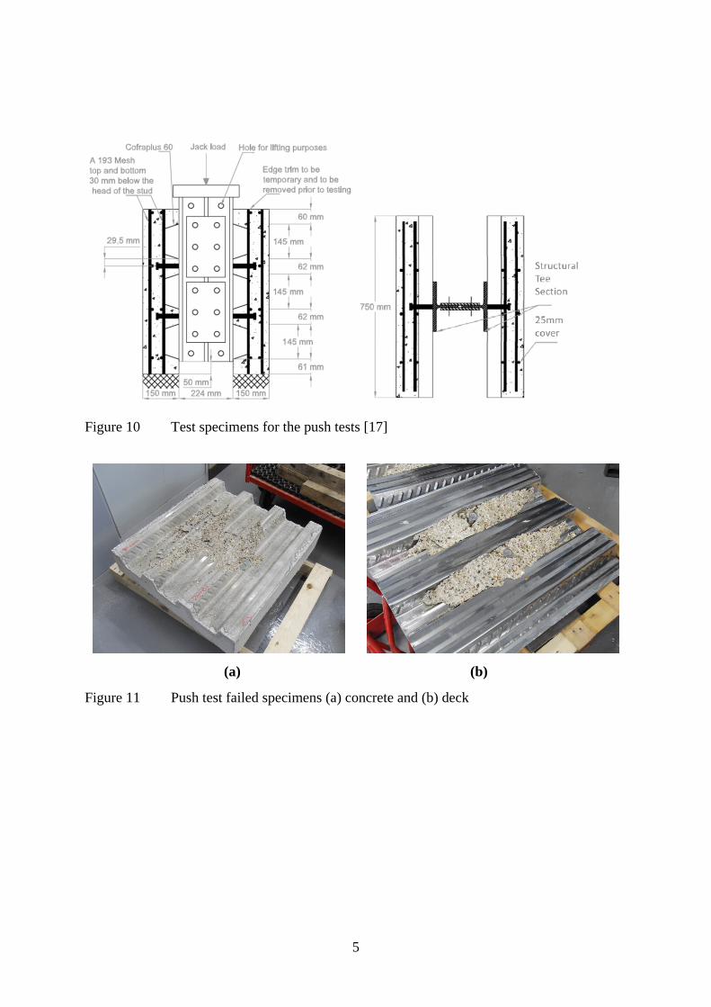
The specimens comprised ArcelorMittal Cofraplus 60 profiles (as in the construction stage and normal stage slab tests) which had a stiffening rib in the centre of the trough. The decks were made from Grade 1.4003 ferritic stainless steel and had a thickness of 0.8 mm. The tests were completed in accordance with EN 1994-1-1 Annex B [30], differing slightly in that the code describes a flat concrete slab without steel decking whereas the test specimens were profiled with ferritic stainless steel sheeting; a schematic of the specimens is given in Figure 10. There were 2 shear studs in each individual slab for all tests, thus resulting in 4 shear studs per test.
12
Three different test configurations were examined as described in Table 7. The first series (where the studs were welded through a narrow strip of ferritic sheeting) was included in order to ensure that the integrity of the welds in the through-deck welded specimens were not affected by the presence of the stiffening rib in the trough of the decking. A profiled sheet with pre-punched holes was then placed over the studs.
All of the specimens demonstrated concrete pull-out failure around the shear connectors (Figure 11). Concrete pull-out failure occurs when the concrete surface fails due to tension occurring across the failure surface. It has been shown that standard push tests are dominated by failure of the concrete around the shear connectors, as was observed in these tests, rather than shearing of the shear connector itself [34]. The typical failure surface for single shear connectors is a cone of concrete starting underneath the head of the shear connector and growing in diameter down the length of the shear connector, although the shape is restricted by the shape of the decking. However, this type of failure would be less likely to occur in a real composite member loaded in bending and, for this reason, many researchers have added a lateral load to the test specimens (e.g. [31, 34]).
Analysis of the test results showed that the ratio of the test load (PRk) to the unfactored Eurocode design capacity (PRd,rib) varied between 0.91 and 1.06, which is similar to the performance of galvanised sheeting. The ductility of the specimens was reasonable with all of the δuk values being around the 6 mm value required by the Eurocode in order to justify the
assumption of ideal plastic behaviour of the shear connection. As stated before, it has been shown that these types of push tests give lower strength and slip resistances than composite beam specimens. In one test programme on carbon steel composite floors, the studs in the beam tests out-performed those in the push tests both in terms of resistance and ductility by 46% and 269%, respectively [32]. On this basis, it is reasonable to deduce that specimens with ferritic stainless steel decking behave at least as well as slabs with galvanised decking and therefore conform to the current requirements of EN 1994-1-1.
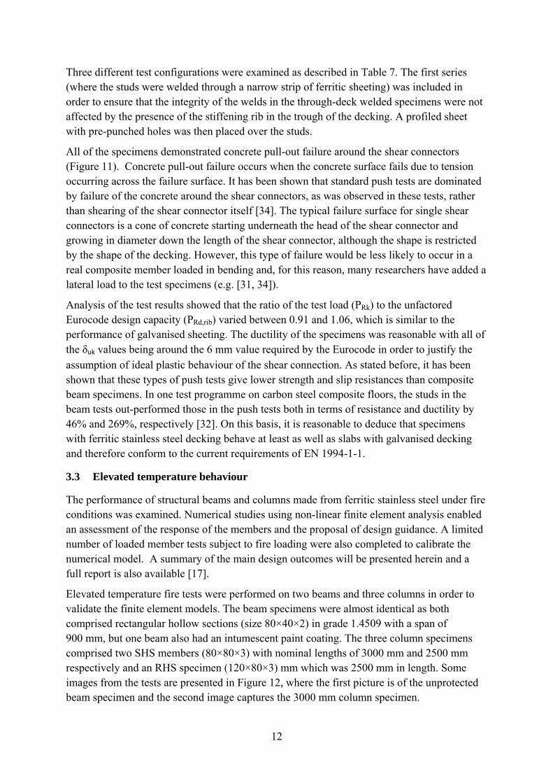
3.3 Elevated temperature behaviour
The performance of structural beams and columns made from ferritic stainless steel under fire conditions was examined. Numerical studies using non-linear finite element analysis enabled an assessment of the response of the members and the proposal of design guidance. A limited number of loaded member tests subject to fire loading were also completed to calibrate the numerical model. A summary of the main design outcomes will be presented herein and a full report is also available [17].
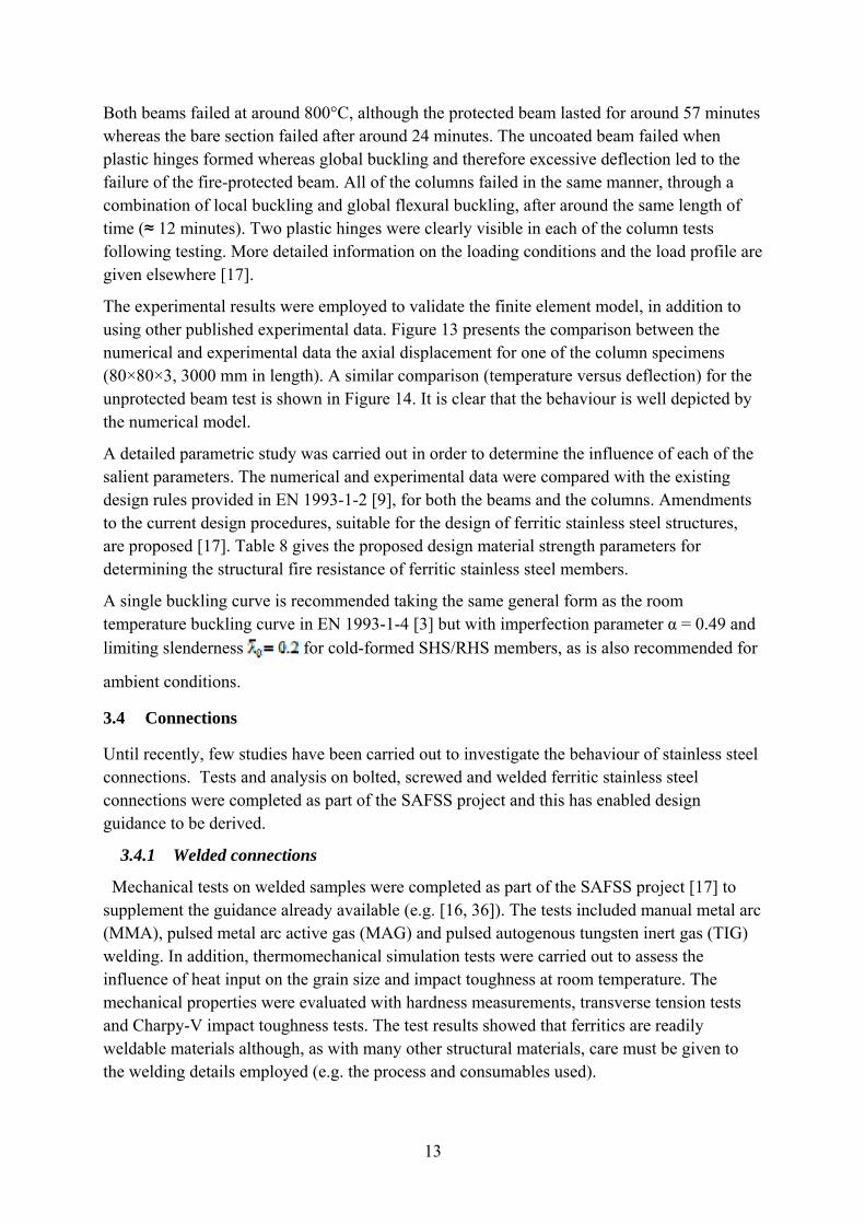
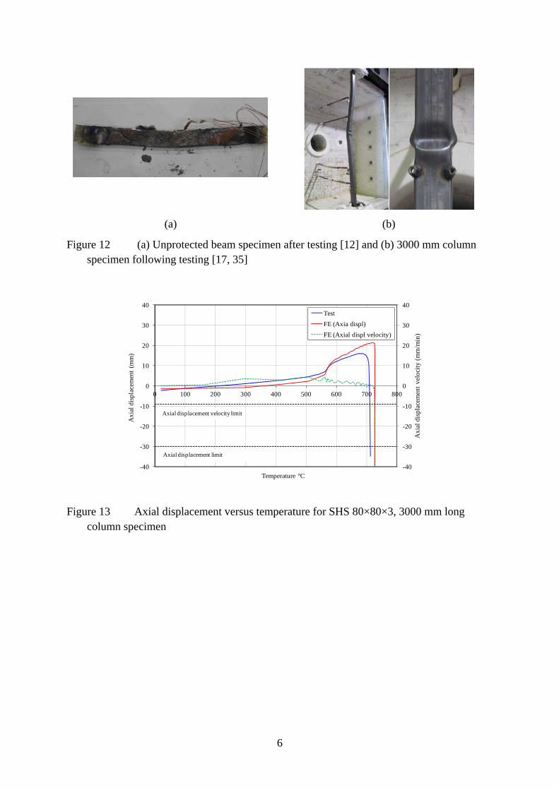
Elevated temperature fire tests were performed on two beams and three columns in order to validate the finite element models. The beam specimens were almost identical as both comprised rectangular hollow sections (size 80×40×2) in grade 1.4509 with a span of 900 mm, but one beam also had an intumescent paint coating. The three column specimens comprised two SHS members (80×80×3) with nominal lengths of 3000 mm and 2500 mm respectively and an RHS specimen (120×80×3) mm which was 2500 mm in length. Some images from the tests are presented in Figure 12, where the first picture is of the unprotected beam specimen and the second image captures the 3000 mm column specimen.
13
Both beams failed at around 800°C, although the protected beam lasted for around 57 minutes whereas the bare section failed after around 24 minutes. The uncoated beam failed when plastic hinges formed whereas global buckling and therefore excessive deflection led to the failure of the fire-protected beam. All of the columns failed in the same manner, through a combination of local buckling and global flexural buckling, after around the same length of time (≈ 12 minutes). Two plastic hinges were clearly visible in each of the column tests following testing. More detailed information on the loading conditions and the load profile are given elsewhere [17].
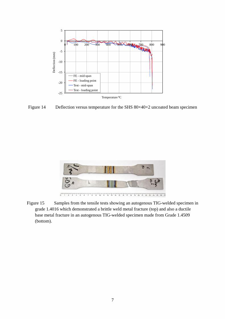
The experimental results were employed to validate the finite element model, in addition to using other published experimental data. Figure 13 presents the comparison between the numerical and experimental data the axial displacement for one of the column specimens (80×80×3, 3000 mm in length). A similar comparison (temperature versus deflection) for the unprotected beam test is shown in Figure 14. It is clear that the behaviour is well depicted by the numerical model.
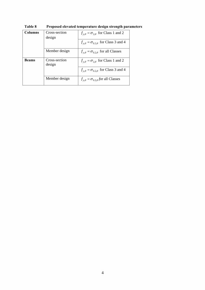
A detailed parametric study was carried out in order to determine the influence of each of the salient parameters. The numerical and experimental data were compared with the existing design rules provided in EN 1993-1-2 [9], for both the beams and the columns. Amendments to the current design procedures, suitable for the design of ferritic stainless steel structures, are proposed [17]. Table 8 gives the proposed design material strength parameters for determining the structural fire resistance of ferritic stainless steel members.
A single buckling curve is recommended taking the same general form as the room temperature buckling curve in EN 1993-1-4 [3] but with imperfection parameter α = 0.49 and limiting slenderness for cold-formed SHS/RHS members, as is also recommended for
ambient conditions.
3.4 Connections
Until recently, few studies have been carried out to investigate the behaviour of stainless steel connections. Tests and analysis on bolted, screwed and welded ferritic stainless steel connections were completed as part of the SAFSS project and this has enabled design guidance to be derived.
3.4.1 Welded connections
Mechanical tests on welded samples were completed as part of the SAFSS project [17] to supplement the guidance already available (e.g. [16, 36]). The tests included manual metal arc (MMA), pulsed metal arc active gas (MAG) and pulsed autogenous tungsten inert gas (TIG) welding. In addition, thermomechanical simulation tests were carried out to assess the influence of heat input on the grain size and impact toughness at room temperature. The mechanical properties were evaluated with hardness measurements, transverse tension tests and Charpy-V impact toughness tests. The test results showed that ferritics are readily weldable materials although, as with many other structural materials, care must be given to the welding details employed (e.g. the process and consumables used).
14
It is recommended that ferritics are welded with austenitic fillers as they provide superior toughness properties compared with ferritic filler metals. Ferritic stainless steel fillers may be used if it is important to have a filler with similar thermal expansion to the base material or similar surface colour of welds or nickel-free welds is particularly important. Special care is needed with autogenous (i.e. without using a filler material) TIG welding since this may lead to lower corrosion resistance as well as loss of ductility and toughness.
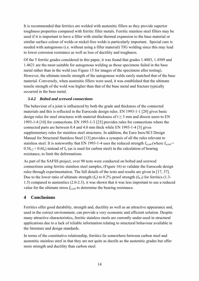
Of the 5 ferritic grades considered in this paper, it was found that grades 1.4003, 1.4509 and 1.4621 are the most suitable for autogenous welding as those specimens failed in the base metal rather than in the weld (see Figure 15 for images of the specimens after testing). However, the ultimate tensile strength of the autogenous welds rarely matched that of the base material. Conversely, when austenitic fillers were used, it was established that the ultimate tensile strength of the weld was higher than that of the base metal and fracture typically occurred in the base metal.
3.4.2 Bolted and screwed connections
The behaviour of a joint is influenced by both the grade and thickness of the connected materials and this is reflected in the Eurocode design rules. EN 1993-1-1 [20] gives basic design rules for steel structures with material thickness of t ≥ 3 mm and directs users to EN 1993-1-8 [10] for connections. EN 1993-1-3 [23] provides rules for connections where the connected parts are between 0.4 and 4.0 mm thick while EN 1993-1-4 [3] gives supplementary rules for stainless steel structures. In addition, the Euro Inox/SCI Design Manual for Structural Stainless Steel [13] provides a synopsis of all the rules relevant to stainless steel. It is noteworthy that EN 1993-1-4 uses the reduced strength fu,red (where fu,red = 0.5f0.2 + 0.6fu) instead of fu (as is used for carbon steel) in the calculation of bearing resistance, to limit the deformations.
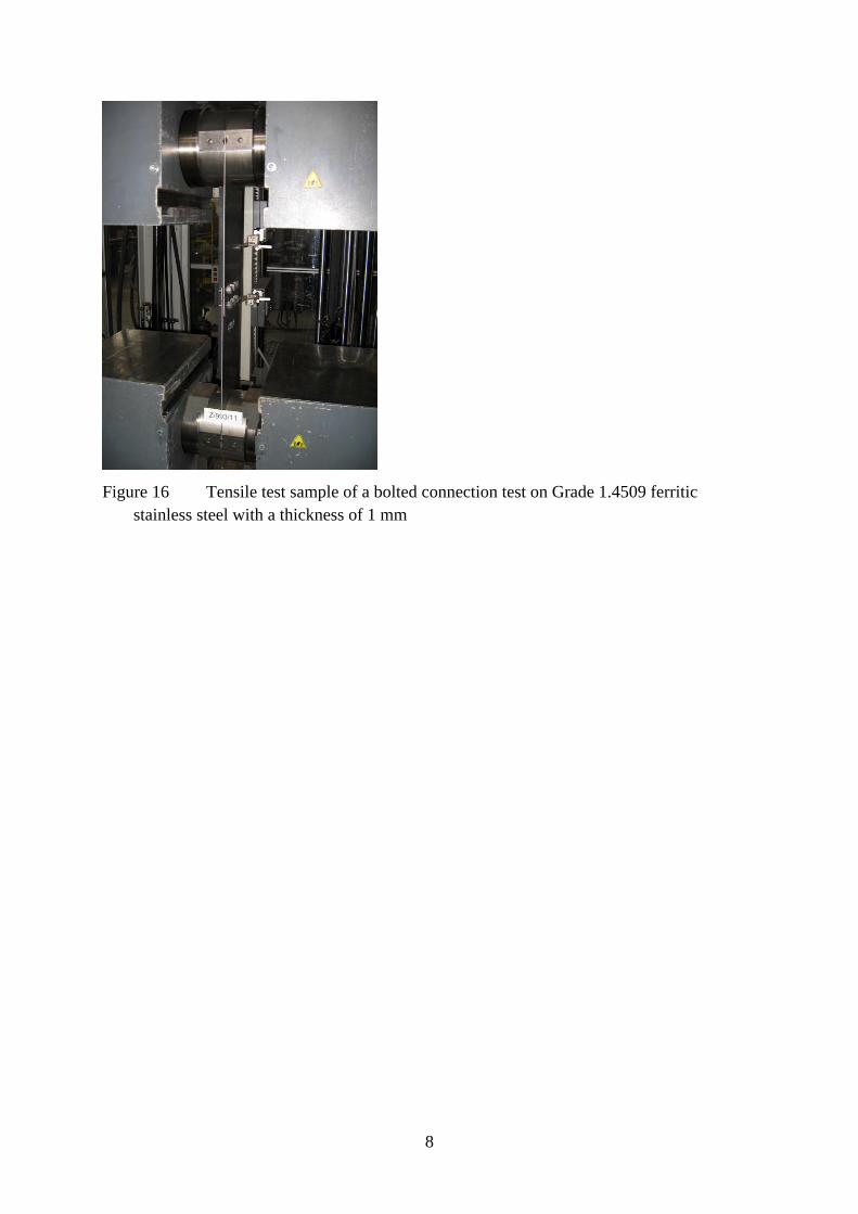
As part of the SAFSS project, over 90 tests were conducted on bolted and screwed connections using ferritic stainless steel samples, (Figure 16) to validate the Eurocode design rules through experimentation. The full details of the tests and results are given in [17, 37]. Due to the lower ratio of ultimate strength (fu) to 0.2% proof strength (f0.2) for ferritics (1.3-1.5) compared to austenitics (2.0-2.5), it was shown that it was less important to use a reduced value for the ultimate stress fu,red to determine the bearing resistance.
4 Conclusions
Ferritics offer good durability, strength and, ductility as well as an attractive appearance and, used in the correct environment, can provide a very economic and efficient solution. Despite many attractive characteristics, ferritic stainless steels are currently under-used in structural applications due to a lack of reliable information relating to structural behaviour available in the literature and design standards.
In terms of the constitutive relationship, ferritics lie somewhere between carbon steel and austenitic stainless steel in that they are not quite as ductile as the austenitic grades but offer more strength and ductility than carbon steel.
15
A recent European structural research project (SAFSS) has generated much useful data, enabling more comprehensive and less conservative structural design rules to be developed. The main aim of this work was to provide practitioners with useful performance data and design guidance so that ferritic stainless steels can be specified in structures with confidence. The performances of both thin-walled ferritic members and composite elements using ferritic stainless steel decking have been studied and design recommendations proposed. It is anticipated that the results of this study will be included in a future edition of the stainless steel design standard EN 1993-1-4.,.
5 Acknowledgments
The research leading to these results received funding from the European Community’s Research Fund for Coal and Steel (RFCS) under Grant Agreement no. RFSR-CT-2010-00026, Structural Applications of Ferritic Stainless Steels. The authors would also like to acknowledge the support of the International Chromium Development Association.
References
[1] Baddoo N.R. Design Guide 27: Structural stainless steel. American Institute of Steel Construction AISC; 2013.
[2] Columbus Stainless Steel Ltd. 3r12 Coastal audit report. 2012.
[3] EN 1993-1-4. Eurocode 3. Design of steel structures: Part 1-4: General rules — Supplementary rules for stainless steels. CEN; 2006.
[4] Wright R.N. Toughness of ferritic stainless steels. ASTM STP 706, Edited by R.A. Lula, American Society for Testing and Materials 1980; pp 2-33.
[5] Afshan S., Rossi B. and Gardner L. Strength enhancements in cold-formed structural sections — Part I: Material testing. Journal of Constructional Steel Research 2013; 83: 177-188.
[6] ASCE/SEI. Specification for the Design of Cold-Formed Stainless Steel Structural Members, ASCE/SEI 8-02; 2002.
[7] South African Bureau of Standards. Code of Practise, Structural Use of Steel, Part 4: The Design of Cold-formed Stainless Steel Structural Members, SABS 0162–4; 1997.
[8] AS/NZS 4673. Australian/New Zealand Standard: Cold-formed stainless steel structures. Sydney Australia; 2001.
[9] EN 1993-1-2. Eurocode 3. Design of steel structures, Part 1-2: General rules — Structural fire design. CEN; 2005.
[10] EN 1993-1-8. Eurocode 3. Design of steel structures, Part 1-8: Design of joints. CEN; 2005.
[11] EN 1993-1-9. Eurocode 3. Design of steel structures, Part 1-9: Fatigue. CEN; 2005.
16
[12] EN 1993-1-10. Eurocode 3. Design of Steel Structures- Part 1-10: Material toughness and through-thickness properties. CEN; 2005.
[13] Euro Inox and SCI. Design manual for structural stainless steel (third edition), Building Series Volume 3; 2006
[14] EN 10088-4. Stainless steels – Part 4: Technical delivery conditions for sheet/plate and strip of corrosion resisting steels for construction purposes. CEN; 2009.
[15] EN 10088-2. Stainless steels – Part 2: Technical delivery conditions for sheet/plate and strip of corrosion resisting steels for general purposes. CEN; to be published in 2014.
[16] Outokumpu Stainless Oy. Outokumpu welding handbook (10th edition). Avesta, Sweden; 2010.
[17] Structural Applications of Ferritic Stainless Steels (SAFSS). Research Fund for Coal and Steel Final Report, 2014 (to be published). Downloadable from www.steel-stainless.org/ferritics (from April 2014)
[18] EN 10088-1. Stainless steels – Part 1: List of stainless steels. CEN; 2005.
[19] EN 10025-2. Hot rolled products of structural steels — Part 2: Technical delivery conditions for non-alloy structural steels. CEN; 2004.
[20] EN 1993-1-1. Eurocode 3. Design of steel structures — Part 1-1: General rules and rules for buildings. CEN; 2005.
[21] Real, E., Arrayago, I., Mirambell, E. and Westeel, R. Comparative study of analytical expressions for the modeling of stainless steel behaviour. Presented at: The Fourth International Structural Stainless Steel Experts Seminar, Ascot, UK; 2012.
[22] Steel Construction Institute. Re-evaluation of EN 1993-1-4 partial resistance factors for stainless steel, RT1533. Steel Construction Institute; 2013.
[23] EN 1993-1-3. Eurocode 3. Design of steel structures: Part 1-3: General rules —Supplementary rules for cold-formed members and sheeting. CEN; 2006.
[24] Mirambell E. and Real E. On the calculation of deflections in structural stainless steel beams: an experimental and numerical investigation. Journal of Constructional Steel Research 2000, 54(1): 109-133.
[25] Gardner L. and Theofanous M. Discrete and continuous treatment of local buckling in stainless steel elements. Journal of Constructional Steel Research 2008. 64(11): 1207-1216.
[26] Bock M., Arrayago I., Real E. and Mirambell E. Study of web crippling in ferritic stainless steel cold formed sections. Thin Walled Structures 2013. 69: 29-44.
[27] Steel Construction Institute. Composite Design of steel framed buildings - In accordance with Eurocodes and the UK National Annexes. P359 Steel Construction Institute SCI; 2011.
17
[28] Blaß H.J. and Saal H. Experimentelle Trayfahigkeitsuntersuchung von Stahlblechprofilen COFRADAL 60 PLUS (In German). Universitat Karlsruhe; 2006.
[29] Suppes A. Prüfbericht Nr. 06-04p. Zulassungsversuche an Verbunddecken Cofraplus 60 (In german). Technische Universität Darmstadt and Insitut für Stahlbau und Werkstoffmechanik, Germany; 2006.
[30] EN 1994-1-1. Eurocode 4. Design of composite steel and concrete structures — Part 1-1: General rules and rules for buildings. CEN; 2004.
[31] Rambo-Roddenberry M. Behavior and strength of welded stud shear connectors. PhD Thesis, Virginia Polytechnic Institute and State University; 2002.
[32] Hicks S. Strength and ductility of headed stud connectors welded in modern profiled steel sheeting. The Structural Engineer 2007; 85(10): 32-38
[33] Cashell K.A. and Baddoo N.R. Ferritic stainless steel in composite construction. In: Proceedings of the Seventh Composite in Construction Conference, Cairns; 2013.
[34] Steel Construction Institute. Effect of key variables on shear connector performance using new push rig, RT1236. Steel Construction Institute; 2009.
[35] Tondini N., Rossi B. and Franssen J-M. Experimental investigation on ferritic stainless steel columns in fire. Fire Safety Journal, in press.
[36] American Welding Society (AWS) Structural welding code – Stainless Steel. D1.6/D1.6M. Miami, USA; 2007.
[37] Talja A. and Torkar M. Lap shear tests of bolted and screwed ferritic stainless steel connections. Thin Walled Structures 2014. In press.
1
Tables - Ferritic stainless steels in structural applications
Table 1 Typical composition of ferritic stainless steel (see text for explanation of symbols)
EN 10088
AISI UNS Typical Cr content (%)
Typical Mo content (%)
Typical Nb content (%)
Typical Ti content (%)
1.4003 - S41003/S40977 10.5-12.5 - - - 1.4016 430 S43000 16-18 - - - 1.4509 441 S43932 17.5-18.5 - <1.0 0.1-0.6 1.4521 444 S44400 17-20 1.8-2.5 - <0.8 1.4621 445 S44500 20 - 0.4 -
Table 2 Physical properties of ferritic stainless steel [9, 17]
Grade Density
Electric resistivity at 20°C
Specific Thermal
capacity at 20°C
Thermal conductivity
at 20°C
Coefficient of thermal expansion
Elastic modulus ×103
g/cm3 Ωmm2/m J/kg°C W/m°C 0~100°C
N/mm2 10-6/°C
1.4003 7.7 0.60 460 28 10.4 220 1.4016 7.7 0.60 460 26 10.0 220 1.4509 7.7 0.60 460 26 10.0 220 1.4521 7.7 0.80 460 26 10.4 220 1.4301 (Austenitic stainless steel)
7.9 0.73 500 15 16 200
Carbon steel
7.7 0.22 440 53 12 210
2
Table 3 Mechanical properties of ferritic stainless steels
Grade
Elastic Modulus,
E
0.2% proof
strength, f0.2
1% proof
strength, f1.0
Ultimate tensile
strength, fu
Elongation at failure,
A Nonlinearity
factor, n
f0.2(EN) fu(EN)
GPa (N/mm2) (N/mm2) (N/mm2) (%) (N/mm2) (N/mm2)
1.4003 194 330 357 493 51 15.4 280 450-650
1.4016 183 311 333 458 38 15.5 260 450-650
1.4509 198 331 353 479 43 18 230 430-630
1.4521 194 375 396 542 44 20.2 300 420-640
1.4621 184 359 373 469 56 20.4 - -
1.4301 - - - - - 8 230 540
S355 - - - - - - 355 510
Table 4 Proposed reduction factors
Temperature (°C)
Group 1 (1.4003 and 1.4016) Group 2 (1.4509, 1.4521 and 1.4621)
k0.2,θ ku,θ k2.0,θ kE,θ k0.2,θ ku,θ k2.0,θ kE,θ
20 1.00 1.00 0.31 1.00 1.00 1.00 0.30 1.00
100 0.93 0.93 0.33 0.98 0.88 0.93 0.31 0.98
200 0.91 0.89 0.35 0.95 0.83 0.91 0.35 0.95
300 0.89 0.87 0.30 0.92 0.78 0.88 0.32 0.92
400 0.87 0.84 0.43 0.86 0.73 0.82 0.40 0.86
500 0.75 0.82 0.46 0.81 0.66 0.78 0.47 0.81
600 0.43 0.33 0.50 0.75 0.53 0.64 0.50 0.75
700 0.16 0.13 0.50 0.54 0.39 0.41 0.50 0.54
800 0.10 0.09 0.50 0.33 0.10 0.11 0.50 0.33
900 0.06 0.07 0.50 0.21 0.04 0.03 0.50 0.21
1000 0.04 0.05 0.50 0.09 0.02 0.01 0.50 0.09
3
Table 5 Recommended buckling parameters for ferritic stainless steel members in compression
Buckling mode Type of member Proposed α
Proposed
0
Current EN 1993-1-4 value for
α
Current EN 1993-1-4
value for 0
Flexural Cold-formed open sections 0.21 0.4 0.49 0.4
Hollow sections 0.49 0.2 0.49 0.4
Welded open sections (major axis) 0.49 0.2 0.49 0.4
Welded open sections (minor axis) 0.76 0.2 0.76 0.2
Torsional-flexural Cold-formed open sections 0.21 0.2 0.34 0.2
Other sections 0.34 0.2 0.34 0.2
Torsional All members 0.34 0.2 0.34 0.2
Table 6 Calculation parameters
Category 1 (EOF) Category 2 (IOF)
SHS/RHS Hat section SHS/RHS Hat section
α 0.07 0.085 0.13 0.14
β 2.14 1.65 0.59 0.81
δ 0.22 0.13 0.14 0.065
ξ 2200 2275 2700 2000
Table 7 Push test programme
Series Number of tests
Details Shape of
slab
Continuity of deck beyond
weld?
Through-deck welded?
1 2 Studs welded through narrow
flat sheet Profiled No Yes
2 3 Studs welded through
continuous profiled deck Profiled Yes Yes
3 3 No through-deck welding Profiled No No
4
Table 8 Proposed elevated temperature design strength parameters
Columns Cross-section design
,2, yf for Class 1 and 2
,2.0, yf for Class 3 and 4
Member design ,2.0, yf for all Classes
Beams Cross-section design
,2, yf for Class 1 and 2
,2.0, yf for Class 3 and 4
Member design ,2.0, yf for all Classes
1
Figures - Ferritic stainless steels in structural applications
Figure 1 Comparison of material stress-strain characteristics for different cold-formed materials (adapted from [5])
Figure 2 Stainless steel atmospheric exposure tests
2
Figure 3 (a) Grade 1.4621 sample from producer A which was exposed in Seville, Spain for 18 months and (b) Grade 1.4509 sample from producer B with a weld and bolt-
holes which was exposed in Tornio, Finland for 18 months
Figure 4 Comparison of experimental (EXP) and finite element (FEM) results [17]
3
Figure 5 Typical layout of a steel-concrete composite floor (image courtesy of SCI)
Figure 6 Cofraplus 60 decking profile used in the composite decking tests
4
Figure 7 Comparison of stress-strain characteristics of ferritic stainless steel coil before being rolled into a decking profile (t = 8 mm) [17]
(a) (b)
Figure 8 (a) Simply supported decking tests and (b) Continuous decking tests [17]
(a) (b)
Figure 9 (a) Long span and (b) short span composite tests [17]
5
Figure 10 Test specimens for the push tests [17]
(a) (b)
Figure 11 Push test failed specimens (a) concrete and (b) deck
6
(a) (b)
Figure 12 (a) Unprotected beam specimen after testing [12] and (b) 3000 mm column specimen following testing [17, 35]
-40
-30
-20
-10
0
10
20
30
40
-40
-30
-20
-10
0
10
20
30
40
0 100 200 300 400 500 600 700 800
Axi
al d
ispl
acem
ent
velo
city
(m
m/m
in)
Axi
al d
ispl
acem
ent
(mm
)
Temperature °C
Test
FE (Axia displ)
FE (Axial displ velocity)
Axial displacement limit
Axial displacement velocity limit
Figure 13 Axial displacement versus temperature for SHS 80×80×3, 3000 mm long column specimen
7
-25
-20
-15
-10
-5
0
5
0 100 200 300 400 500 600 700 800 900
Def
lect
ion
(mm
)
Temperature 0C
FE - mid-span
FE - loading point
Test - mid-span
Test - loading point
Figure 14 Deflection versus temperature for the SHS 80×40×2 uncoated beam specimen
Figure 15 Samples from the tensile tests showing an autogenous TIG-welded specimen in grade 1.4016 which demonstrated a brittle weld metal fracture (top) and also a ductile base metal fracture in an autogenous TIG-welded specimen made from Grade 1.4509 (bottom).
8
Figure 16 Tensile test sample of a bolted connection test on Grade 1.4509 ferritic stainless steel with a thickness of 1 mm


