Loughborough UniversityInstitutional Repository
Extensional flowcharacterisation and
extrusion blow moulding ofhigh density polyethylene
modified by calciumcarbonate
This item was submitted to Loughborough University's Institutional Repositoryby the/an author.
Citation: HAWORTH, B. and JUMPA, S., 1999. Extensional flow character-isation and extrusion blow moulding of high density polyethylene modified bycalcium carbonate. Plastics, Rubber and Composites, 28 (8), pp. 363-378
Additional Information:
• This article was published in the journal, Plastics, Rubberand Composites [ c© Maney Publishing] and is available at:http://www.maney.co.uk/search?fwaction=show&fwid=199
Metadata Record: https://dspace.lboro.ac.uk/2134/4228
Version: Published
Publisher: c© Maney
Please cite the published version.

This item was submitted to Loughborough’s Institutional Repository (https://dspace.lboro.ac.uk/) by the author and is made available under the
following Creative Commons Licence conditions.
For the full text of this licence, please go to: http://creativecommons.org/licenses/by-nc-nd/2.5/
Pub
lishe
d by
Man
ey P
ublis
hing
(c)
IOM
Com
mun
icat
ions
Ltd
Extensional flow characterisation and extrusionblow moulding of high density polyethylene
modified by calcium carbonateB. Haworth and S. Jumpa
Free surface elongational flow properties, including transient state stressgrowth and melt rupture data, have been measured on a range of calciumcarbonate filled high density polyethylene (HDPE) compounds, using aRutherford elongational rheometer operating at constant strain rate inthe range 0·1–6·0 s−1. Results show that polymer molecular weight has astrong influence on both tensile stress growth and melt rupture data; in-creasing elongational strain rate decreases the stress growth coefficient,in all compounds. At any specific elongational strain rate, the stress growthcoefficient increases with volume fraction of particulate additives and alsowhen using additives of fine particle size, as a result of packing fraction effects.Acid coatings added at super-monolayer levels influence the viscosity of highlyfilled compounds, by internal lubrication.
Dynamic extrusion data obtained by experimental blow moulding of calciumcarbonate modified HDPE materials show that modifications to melt stateshear modulus result in reduced die swell, to an extent determined by fillercoating. In combination with die swell, higher extensional viscosity of filledHDPE contributes significantly to enhanced parison sag resistance. Solid statemodulus enhancement was consistently observed in calcium carbonate filledHDPE containers and if excellent filler dispersion can be achieved, it is feasibleto retain the ductile mode failure of unfilled HDPE when containers aresubjected to high velocity impact loads. PRC/1576
© 1999 IoM Communications Ltd. At the time the work was carried outthe authors were at the Institute of Polymer Technology and MaterialsEngineering, Loughborough University, Loughborough, Leicestershire LE113TU, UK. Dr Jumpa is now in the Department of Chemistry, King Mong-kut’s Institute of Science and Technology Ladkrabang, Chalongkrung Road,Ladkrabang, Bangkok 10520, Thailand. This paper was presented at ‘Advancesin Blow Moulding’ held in Loughborough, UK on 30 June–1 July 1998.
INTRODUCTION AND BACKGROUND (ii) the interfacial adhesion characteristics betweenMineral fillers can be loosely classified as inactive the particles and the resin matrix, which influ-(extenders, or cost reducing additives) or as active ence the ultimate mechanical properties of the(functional ) additives, which induce specific changes composite materials.in properties so that the compound largely meets the Incorporation of particulate additives into a resinrequirements demanded of it.1 Currently, there is leads to modified processing behaviour and occasion-renewed interest in the use of mineral fillers to achieve ally to a subsequent deterioration of the ultimateenhanced processing of thermoplastics, particularly if mechanical performance.7 However, some importantin addition, some specific physical properties of the aspects of mechanical behaviour can be significantlyproduct can also be improved. Fillers can change the enhanced by filler addition; for example, enhancedcharacteristics of a polymer in two ways: the prop- melt fracture stress occurs when processing fillederties of the particles (size, shape, modulus, and surface elastomers.8 Toughness enhancement has also beenenergy) can have profound effects on melt state and noted in polyalkenes and in brittle matrix polymers,9solid phase mechanical behaviour and also a change
as long as certain criteria are fulfilled. For example,in the micromorphology of the solidified polymer
a critical factor that influences mechanical propertiesmay occur, giving rise to differences in the observed
of the compound is the state of particle dispersion insolid state properties. For example, increases inthe matrix.10,11 To facilitate filler dispersion, the filleraddition level of fillers (such as CaCO3 and carbonis often surface treated with a coating, which acts asblack, (CB)) in polyalkenic compounds generallya wetting agent by reducing the specific surface freeimproves low strain properties such as tensile modu-energy of the additive particles. Common coatinglus,2–5 but may decrease properties relating to energyagents for mineral fillers are fatty acids, from whichabsorption, such as ultimate tensile strength2,6 andthe acid group reacts onto the filler surface. However,elongation at break.3,5the hydrocarbon chain is unable to react chemicallyAdditionally, two important technical issues mustwith the matrix and interacts only weakly, producingbe considered when using fillers:low bond strength between filler and matrix.12 The(i) the rheological behaviour of the filled polymereffect is therefore one of reduced physical interaction,(melt state mechanical behaviour), whichrather than a direct, adhesion promoting phenom-governs processability and influences micro-
structure development enon. In summary, treatment of CaCO3 with stearic
Plastics, Rubber and Composites 1999 Vol. 28 No. 8 363ISSN 1465–8011
Pub
lishe
d by
Man
ey P
ublis
hing
(c)
IOM
Com
mun
icat
ions
Ltd
364 Haworth and Jumpa Extensional flow characterisation and extrusion blow moulding of CaCO3
modified HDPE
acid decreases the surface energy of the filler and oped by Smoker26 who studied the elongational flowbehaviour of low density polyethylene (LDPE) forparticle–particle interactions within agglomerated
regions. This facilitates filler dispersion and also film blowing applications. Further modifications ofthe RER apparatus were subsequently introduced byleads to enhanced mechanical performance of the
compounds.13,14 Previous research15 using coatings Axtell and Haworth27,28 who used the RER to studythe viscoelastic behaviour of poly(ethylene terephthal-of different aliphatic chain length in filled polyethylene
has demonstrated that when longer chain coating ate) (PET) in the rubbery region at temperaturesabove the primary glass transition temperature Tg , toagents are used to treat the fillers, low strain modulus
and yield stress are enhanced but compounds are simulate the stretch–blow moulding process. Otherapplications have been focused upon rigid PVC com-more prone to brittle mode failure as a result of lower
energy absorption. pounds, to simulate elongational deformation andflow in processes such as thermoforming, and bubbleImprovements in process equipment have been
made to enhance efficiency in the compounding of formation in foam extrusion.29 Very little previousresearch has been reported relating to the elongationalfillers and other particulate additives16 and a study
of the rheological characteristics of newly formulated deformation and rupture of filled polymer melts. Ithas been reported30 that in fibre filled polypropylenecompounds is a most important step in examining
their behaviour in polymer conversion processes such compounds, the elongational viscosity is not only afunction of time but also of strain rate. Other work-as extrusion blow moulding. The viscoelastic flow
behaviour of particle filled polymer melts depends ers21 have reported that the elongational viscosity ofCaCO3 filled polystyrene increases with filler contentupon the filler characteristics, the nature of the (poly-
mer/particle and particle/particle) interfaces, the and/or reduction of particle size.This research focuses on composite systems of highdegree of dispersion, and the orientation distribution
of the filler particles.17 The presence of other additives, molecular weight, high density polyethylene (HDPE)resins compounded with a number of CaCO3 fillerseven in small quantities, may be crucial in the compos-
ite system because they may interfere with the resin/ varying in particle size, surface coating, and additionlevel. The filler coatings include stearic acid, which isfiller interface18 and may also influence the intera-
ction between the compound and machinery surfaces a widely used coating agent in filled polyalkeniccompounds, and an acid terminated polyethyleneto create a wall slip effect at the flow boundary.19
Generally, the presence of filler particles increases the (ATPE), a newly developed material based upon lowmolar mass polyethylene chains terminated at onepolymer melt viscosity,20 with highest levels of vis-
cosity being observed at higher filler content3,5 or end with an acid group. Since similar compounds arebeing developed specifically for applications in whichwith smaller filler particle size additives.21 A reduction
in the viscosity of the compound is sometimes their processability is important, the overall objectiveof the research is to characterise the elongationalobserved when either a coupling or coating agent is
present.3,20,21 deformation properties of CaCO3 modified HDPEand to relate these properties to the processing behav-Most studies of the rheological behaviour of
particle filled polymer melts reported in the literature iour and selected product attributes of containersmanufactured by extrusion blow moulding.involve shear flow, rather than elongational (exten-
sional ) flow. This is partly due to perceived experi-mental difficulties and also a lack of recognition ofthe importance of elongational flows in polymer ELONGATIONAL RHEOMETRY: OVERVIEW
OF FREE SURFACE DEFORMATIONprocessing.22 Elongational deformation is often appar-ent as a free surface flow, i.e. there is no boundary In polymer processing, the stress distributions that
create the deformation required for shaping arebetween the melt and the rheometer (viscometer)walls. This is in contrast to shear deformation, in also responsible for structure development, together
with the thermal history during the cooling phase.which the melt is in contact with and is shearedbetween the rheometer walls.23 Elongational flows Appropriate polymer properties relevant to the ther-
momechanical history must be carefully characterisedalso occur as constrained flows, e.g. in convergingsections of extrusion dies.24 The elongational mode offline, if process simulation and modelling techniques
are accurately to simulate real time manufacturingof deformation is observed in several phases of blowmoulding processes, including low strain rate gravi- processes. While this holds true for simple polymer
systems, interrelationships between processing, struc-metric loading (in which the elongational stress tendsto deform the parison vertically, along its principal ture development, and properties hold even greater
significance (and are made more complex) by theaxis: parison sagging) and during the inflation phase,which is a high strain rate deformation. Therefore, to addition of significant quantities of particulate addi-
tives, in heterogeneous polymer composites. This isachieve satisfactory blow moulded products, whichdepends upon both material distribution and polymer notable when processing thermoplastics modified by
particulate fillers, for which the particles (and otherproperties, knowledge of rheological properties isrequired to include both shear and elongational additives such as coatings and coupling agents) are
known to have a strong influence on different aspectsmodes of deformation.The research reported in the present paper features of flow and deformation behaviour.12
The flow mechanism is also important in thisa uniaxial elongational rheometer, the Rutherfordelongational rheometer (RER), which provides free context. For example, if a process requires shear flow
properties of polymer melts between fixed boundariessurface deformation, and was principally based on aninstrument designed by Munstedt.25 It was first devel- (constrained flows), the influence of filler coatings
Plastics, Rubber and Composites 1999 Vol. 28 No. 8
Pub
lishe
d by
Man
ey P
ublis
hing
(c)
IOM
Com
mun
icat
ions
Ltd
Haworth and Jumpa Extensional flow characterisation and extrusion blow moulding of CaCO3
modified HDPE 365
on external lubrication becomes highly significant. In terms of a tensile stress growth coefficient (TSGC)34determined ascontrast, wall slip behaviour is clearly irrelevant to
free surface extensional deformations such as parisonl(eH , t)=sE(t)/eH . . . . . . . . . . (4)
sag and inflation, in extrusion blow moulding.The processing advantages afforded by filled If and when the tensile stress levels out to a constant
value, the limiting tensile stress growth coefficientthermoplastics are currently being exploited on anincreasing scale. However, characterisation of the represents the elongational viscosity lelongational deformation and flow properties of these
l=l(eH)= limt�2
[l(eH , t)] . . . . . . . (5)materials has received relatively little coverage inrelevant scientific journals. For the research studies
In this paper, the influence of some particulate CaCO3that are reported in this paper, free surface deforma-additives on the extensional flow and deformation of
tions were applied under conditions of constant exten-some high molar mass HDPE polymers are consid-
sional strain rate. The RER used in the research isered and analysed using the RER operating in con-
a free surface deformation elongational rheometer,stant strain rate mode according to the principles
similar in principle to an instrument designed pre-defined above.
viously,25 which measures force and extension as afunction of experimental time, in order to compute
MATERIALS AND EXPERIMENTALthe rheological parameters defined below. The motioninvolves deformation between coaxial clamps, one of HDPE polymerswhich moves relative to the other, according to the A range of RigidexA HDPE polymers differing inpre-set conditions. Some subsequent modifications to molecular weight Mw and distribution were suppliedthe original design and updates to the data capture by BP Chemicals Ltd (Grangemouth, UK) and haveand processing methods have been detailed in other been coded as shown in Table 1. Grades A, B, and Dpublications.31,32 A review paper by Meissner33 has have variable molecular weight, but with a similarprovided an appropriate summary of research carried molecular weight distribution. The effect of changingout using this type of equipment. molecular weight distribution can be made by com-
When this design of rheometer is operating under parison of grades C and D, which have a similarclosed loop, constant strain rate conditions, it can be molecular weight. All molecular weight data are nom-shown that the specimen length varies with time inal values, obtained using high temperature gel per-according to meation chromatography.
L t=L 0 exp(eHt) . . . . . . . . . . (1)
Fillers and coatingswhere L 0 is the initial specimen length, eH is theThe CaCO3 fillers were supplied by ECCHencky ( logarithmic) strain rate, and t is time. ThisInternational (St. Austell, UK) and varied in terms ofexpression may be rewritten in terms of axial velo-particle size distribution, and coating type/additioncity Vt level. The materials in the MicrocalA range are high
Vt= eHL 0 exp (eHt) . . . . . . . . . . (2) purity grades, derived from Italian marble. Fur-ther details of these materials are given in Table 2.Since this type of experiment involves the attainmentMicrocalA C110S was supplied with stearic acidof large strains, the stress function must account forcoating applied by the manufacturer, whereas allthe reduction in specimen cross-section that occurs.organoacid coatings on as supplied (uncoated) fillersIt may be shown that the true extensional stress sE were applied by an in house, dry blending process.can be expressed in terms of transient length L t andThis technique uses a high speed Fielder batch mixer,axial force Ft bywith process conditions defined by monitoring the
sE=FtL t/A0L 0 . . . . . . . . . . (3) time dependent filler–coating reaction using FTIRin diffuse reflectance (DRIFT) mode and has beenwhere A0 is the initial specimen cross-sectional area.described in detail elsewhere.15,35 The ATPE polymerIn a constant elongational strain rate test, motion(grade AC X495) has an approximate molar mass ofwith constant stretch history is achieved and this type4550 g mol−1, as determined from its acid number ofof deformation is called steady, simple (uniaxial )
elongation. When the elongational strain rate isheld constant, starting at time t=0, the tensile stress Table 2 Measured particle size data of CaCO
3increases as a function of time. Usually, the results of fillers* and details of applied coatingsa tensile stress growth experiment are interpreted in
BETsurface
Particle size, area,CaCO
3filler mm Coating m2 g−1Table 1 Nominal molecular weight data for HDPE
polymers used in rheological analysisRLO6083 0·55 Uncoated 17·3Microcal C110 1·80 Stearic acid, ATPE 4·7Molecular weight, Molecular weight
Polymer g mol−1 distribution (various levels)Microcal C110S* 1·71 Stearic acid 6·5
HDPE-A 350 000 14·3 Microcal C140 10·82 Uncoated 1·2HDPE-B 160 000 8·8
* All fillers were dry coated using the techniques described,HDPE-C 95 000 3·5except Microcal C110S, which was coated at source by theHPDE-D 110 000 7·9material supplier, ECC International.
Plastics, Rubber and Composites 1999 Vol. 28 No. 8
Pub
lishe
d by
Man
ey P
ublis
hing
(c)
IOM
Com
mun
icat
ions
Ltd
366 Haworth and Jumpa Extensional flow characterisation and extrusion blow moulding of CaCO3
modified HDPE
12·4 mg KOH/g, and was supplied by Allied Signal research. Ambient temperature mechanical propertymeasurements were obtained firstly in tension at lowCorporation (Belgium).deformation rates, using a JJ Lloyd vertical tenso-meter operating at a crosshead speed of 20 mm min−1.CompoundingIn addition, the response to high strain rate impactAll HDPE polymers were initially combined withloading conditions was determined using a Rosand40% (nominal, by weight) of CaCO3 , using aIFW5 instrumented impact unit, testing rectangularco-rotating twin screw extruder supplied by APVspecimens cut from ‘as processed’ wall sections ofIndustrial Extruder Division (Newcastle Under Lyme,containers. A test temperature of −40°C was selected,UK). The extruder has a screw diameter of 30 mmwith 60×60 mm specimens pre-cooled using a liquidand a nominal length/diameter ratio of 30 : 1; overallnitrogen supply to a constant temperature environ-output rate was ~12 kg h−1 in all cases and screwmental chamber. This temperature was known to liedesign was optimised for ‘single stage’ dispersiveclose to a ductile–brittle transition for these compos-mixing. In addition, HDPE–CaCO3 compounds wereites and was selected because the test specimen thick-prepared as a function of filler content using polymerness was too low to enable geometry independent,HDPE-B, up to a maximum additive volume fractionbrittle mode fracture data to be obtained.of ~0·30. In all cases, measurements of extruder
Finally, the respective influences of polymer crys-torque (related to specific energy input) and melttallinity, crystalline texture, and orientation werepressure (at the die entry region) were made whenexamined using differential thermal analysis (DTA)steady state processing was achieved, in order toand by optical microscopy (polarised light mode),generate real time measurements with which torespectively.characterise dispersive mixing.
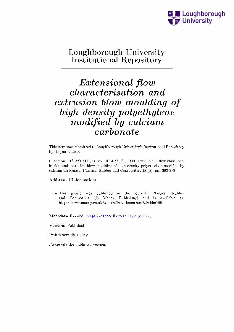
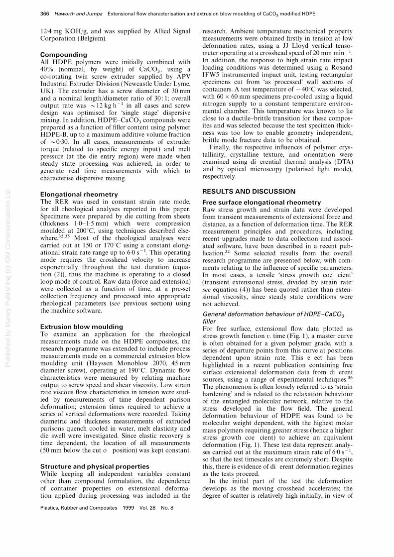
RESULTS AND DISCUSSIONElongational rheometryThe RER was used in constant strain rate mode, Free surface elongational rheometryfor all rheological analyses reported in this paper. Raw stress growth and strain data were developedSpecimens were prepared by die cutting from sheets from transient measurements of extensional force and(thickness 1·0–1·5 mm) which were compression distance, as a function of deformation time. The RERmoulded at 200°C, using techniques described else- measurement principles and procedures, includingwhere.32,35 Most of the rheological analyses were recent upgrades made to data collection and associ-carried out at 150 or 170°C using a constant elong- ated software, have been described in a recent pub-ational strain rate range up to 6·0 s−1. This operating lication.32 Some selected results from the overallmode requires the crosshead velocity to increase research programme are presented below, with com-exponentially throughout the test duration (equa- ments relating to the influence of specific parameters.tion (2)), thus the machine is operating to a closed In most cases, a tensile ‘stress growth coefficient’loop mode of control. Raw data (force and extension) (transient extensional stress, divided by strain rate:were collected as a function of time, at a pre-set see equation (4)) has been quoted rather than exten-collection frequency and processed into appropriate sional viscosity, since steady state conditions wererheological parameters (see previous section) using not achieved.the machine software. General deformation behaviour of HDPE–CaCO
3fillerExtrusion blow moulding For free surface, extensional flow data plotted asTo examine an application for the rheological stress growth function v. time (Fig. 1), a master curvemeasurements made on the HDPE composites, the is often obtained for a given polymer grade, with aresearch programme was extended to include process series of departure points from this curve at positionsmeasurements made on a commercial extrusion blow dependent upon strain rate. This effect has beenmoulding unit (Hayssen Monoblow 2070, 45 mm highlighted in a recent publication containing freediameter screw), operating at 190°C. Dynamic flow surface extensional deformation data from differentcharacteristics were measured by relating machine sources, using a range of experimental techniques.36output to screw speed and shear viscosity. Low strain The phenomenon is often loosely referred to as ‘strainrate viscous flow characteristics in tension were stud- hardening’ and is related to the relaxation behaviouried by measurements of time dependent parison of the entangled molecular network, relative to thedeformation; extension times required to achieve a stress developed in the flow field. The generalseries of vertical deformations were recorded. Taking deformation behaviour of HDPE was found to bediametric and thickness measurements of extruded molecular weight dependent, with the highest molarparisons quench cooled in water, melt elasticity and mass polymers requiring greater stress (hence a higherdie swell were investigated. Since elastic recovery is stress growth coefficient) to achieve an equivalenttime dependent, the location of all measurements deformation (Fig. 1). These test data represent analy-(50 mm below the cut off position) was kept constant. ses carried out at the maximum strain rate of 6·0 s−1,
so that the test timescales are extremely short. Despitethis, there is evidence of different deformation regimesStructure and physical properties
While keeping all independent variables constant as the tests proceed.In the initial part of the test the deformationother than compound formulation, the dependence
of container properties on extensional deforma- develops as the moving crosshead accelerates; thedegree of scatter is relatively high initially, in view oftion applied during processing was included in the
Plastics, Rubber and Composites 1999 Vol. 28 No. 8
Pub
lishe
d by
Man
ey P
ublis
hing
(c)
IOM
Com
mun
icat
ions
Ltd
Haworth and Jumpa Extensional flow characterisation and extrusion blow moulding of CaCO3
modified HDPE 367
10_2 10_1 100 101
107
106
105
104
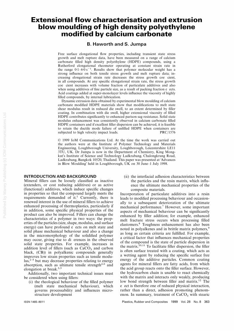
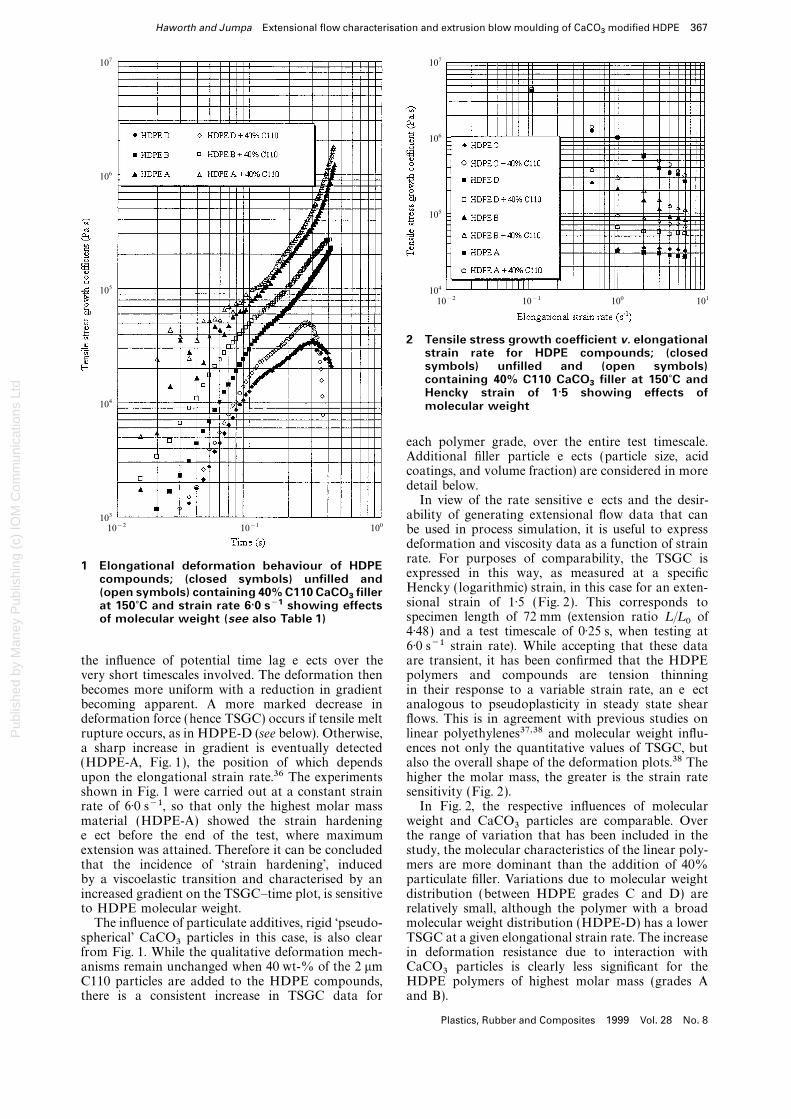
2 Tensile stress growth coefficient v. elongationalstrain rate for HDPE compounds; (closedsymbols) unfilled and (open symbols)containing 40% C110 CaCO
3filler at 150?C and
Hencky strain of 1·5 showing effects ofmolecular weight
each polymer grade, over the entire test timescale.Additional filler particle effects (particle size, acidcoatings, and volume fraction) are considered in moredetail below.
In view of the rate sensitive effects and the desir-ability of generating extensional flow data that canbe used in process simulation, it is useful to expressdeformation and viscosity data as a function of strain
10_2 10_1 100
107
106
105
104
103
rate. For purposes of comparability, the TSGC is1 Elongational deformation behaviour of HDPEexpressed in this way, as measured at a specificcompounds; (closed symbols) unfilled andHencky ( logarithmic) strain, in this case for an exten-(open symbols) containing 40% C110 CaCO
3filler
sional strain of 1·5 (Fig. 2). This corresponds toat 150?C and strain rate 6·0 s−1 showing effectsspecimen length of 72 mm (extension ratio L /L 0 ofof molecular weight (see also Table 1)4·48) and a test timescale of 0·25 s, when testing at6·0 s−1 strain rate). While accepting that these dataare transient, it has been confirmed that the HDPEthe influence of potential time lag effects over the
very short timescales involved. The deformation then polymers and compounds are tension thinningin their response to a variable strain rate, an effectbecomes more uniform with a reduction in gradient
becoming apparent. A more marked decrease in analogous to pseudoplasticity in steady state shearflows. This is in agreement with previous studies ondeformation force (hence TSGC) occurs if tensile melt
rupture occurs, as in HDPE-D (see below). Otherwise, linear polyethylenes37,38 and molecular weight influ-ences not only the quantitative values of TSGC, buta sharp increase in gradient is eventually detected
(HDPE-A, Fig. 1), the position of which depends also the overall shape of the deformation plots.38 Thehigher the molar mass, the greater is the strain rateupon the elongational strain rate.36 The experiments
shown in Fig. 1 were carried out at a constant strain sensitivity (Fig. 2).In Fig. 2, the respective influences of molecularrate of 6·0 s−1, so that only the highest molar mass
material (HDPE-A) showed the strain hardening weight and CaCO3 particles are comparable. Overthe range of variation that has been included in theeffect before the end of the test, where maximum
extension was attained. Therefore it can be concluded study, the molecular characteristics of the linear poly-mers are more dominant than the addition of 40%that the incidence of ‘strain hardening’, induced
by a viscoelastic transition and characterised by an particulate filler. Variations due to molecular weightdistribution (between HDPE grades C and D) areincreased gradient on the TSGC–time plot, is sensitive
to HDPE molecular weight. relatively small, although the polymer with a broadmolecular weight distribution (HDPE-D) has a lowerThe influence of particulate additives, rigid ‘pseudo-
spherical’ CaCO3 particles in this case, is also clear TSGC at a given elongational strain rate. The increasein deformation resistance due to interaction withfrom Fig. 1. While the qualitative deformation mech-
anisms remain unchanged when 40 wt-% of the 2 mm CaCO3 particles is clearly less significant for theHDPE polymers of highest molar mass (grades AC110 particles are added to the HDPE compounds,
there is a consistent increase in TSGC data for and B).
Plastics, Rubber and Composites 1999 Vol. 28 No. 8
Pub
lishe
d by
Man
ey P
ublis
hing
(c)
IOM
Com
mun
icat
ions
Ltd
368 Haworth and Jumpa Extensional flow characterisation and extrusion blow moulding of CaCO3
modified HDPE
1.0x10⁶
8.0x10⁵
6.0x10⁵
4.0x10⁵
2.0x10⁵
0
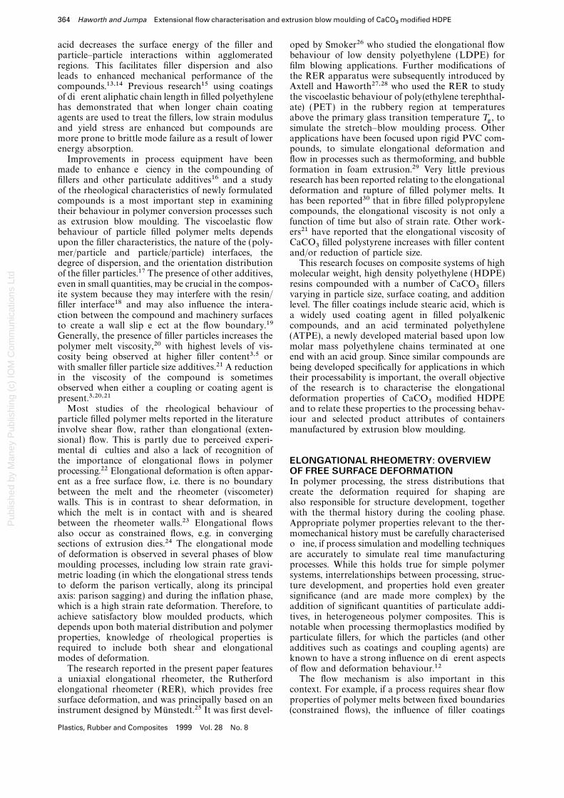
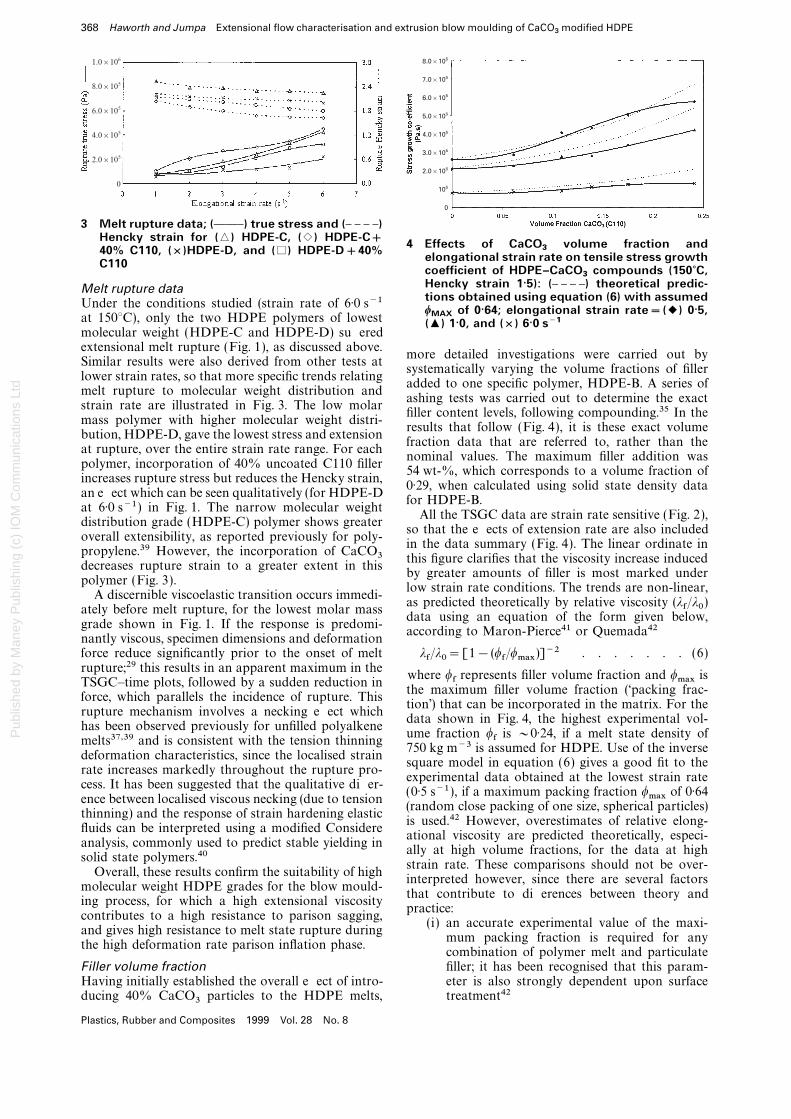
3 Melt rupture data; (CCD) true stress and (D D D D)
8.0x10⁵
7.0x10⁵
6.0x10⁵
5.0x10⁵
4.0x10⁵
3.0x10⁵
2.0x10⁵
105
0
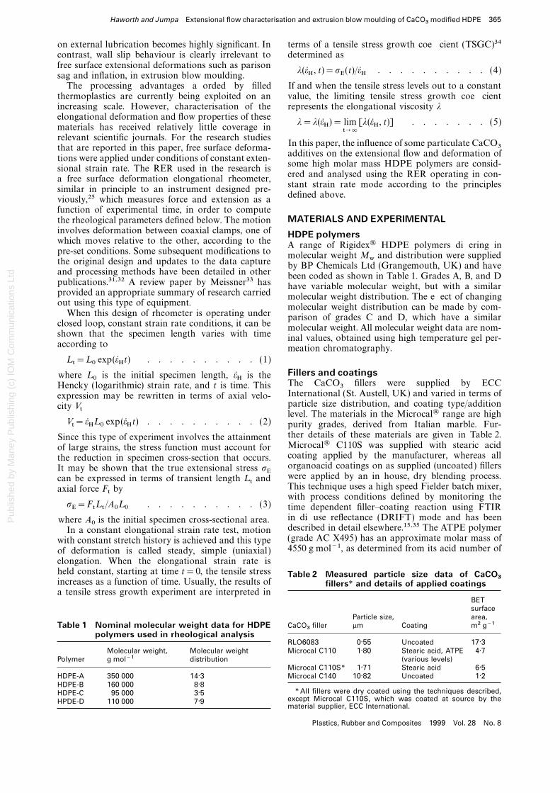
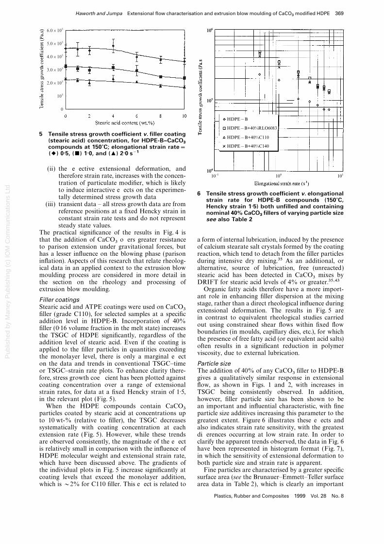
Hencky strain for (6) HDPE-C, (1) HDPE-C+ 4 Effects of CaCO3
volume fraction and40% C110, (×)HDPE-D, and (%) HDPE-D+40% elongational strain rate on tensile stress growthC110 coefficient of HDPE–CaCO3
compounds (150?C,Hencky strain 1·5): (D D D D) theoretical predic-Melt rupture datations obtained using equation (6) with assumed
Under the conditions studied (strain rate of 6·0 s−1w
MAXof 0·64; elongational strain rate=(2) 0·5,
at 150°C), only the two HDPE polymers of lowest (+) 1·0, and (×) 6·0 s−1molecular weight (HDPE-C and HDPE-D) sufferedextensional melt rupture (Fig. 1), as discussed above.
more detailed investigations were carried out bySimilar results were also derived from other tests at
systematically varying the volume fractions of fillerlower strain rates, so that more specific trends relating
added to one specific polymer, HDPE-B. A series ofmelt rupture to molecular weight distribution and
ashing tests was carried out to determine the exactstrain rate are illustrated in Fig. 3. The low molar
filler content levels, following compounding.35 In themass polymer with higher molecular weight distri-
results that follow (Fig. 4), it is these exact volumebution, HDPE-D, gave the lowest stress and extension
fraction data that are referred to, rather than theat rupture, over the entire strain rate range. For each
nominal values. The maximum filler addition waspolymer, incorporation of 40% uncoated C110 filler
54 wt-%, which corresponds to a volume fraction ofincreases rupture stress but reduces the Hencky strain,
0·29, when calculated using solid state density dataan effect which can be seen qualitatively (for HDPE-D
for HDPE-B.at 6·0 s−1 ) in Fig. 1. The narrow molecular weight
All the TSGC data are strain rate sensitive (Fig. 2),distribution grade (HDPE-C) polymer shows greater
so that the effects of extension rate are also includedoverall extensibility, as reported previously for poly-
in the data summary (Fig. 4). The linear ordinate inpropylene.39 However, the incorporation of CaCO3 this figure clarifies that the viscosity increase induceddecreases rupture strain to a greater extent in this
by greater amounts of filler is most marked underpolymer (Fig. 3).
low strain rate conditions. The trends are non-linear,A discernible viscoelastic transition occurs immedi-
as predicted theoretically by relative viscosity (lf/l0 )ately before melt rupture, for the lowest molar massdata using an equation of the form given below,
grade shown in Fig. 1. If the response is predomi-according to Maron-Pierce41 or Quemada42
nantly viscous, specimen dimensions and deformationforce reduce significantly prior to the onset of melt lf/l0=[1− (wf/wmax)]−2 . . . . . . . (6)rupture;29 this results in an apparent maximum in the
where wf represents filler volume fraction and wmax isTSGC–time plots, followed by a sudden reduction in
the maximum filler volume fraction (‘packing frac-force, which parallels the incidence of rupture. This
tion’) that can be incorporated in the matrix. For therupture mechanism involves a necking effect which
data shown in Fig. 4, the highest experimental vol-has been observed previously for unfilled polyalkene
ume fraction wf is ~0·24, if a melt state density ofmelts37,39 and is consistent with the tension thinning
750 kg m−3 is assumed for HDPE. Use of the inversedeformation characteristics, since the localised strain
square model in equation (6) gives a good fit to therate increases markedly throughout the rupture pro-
experimental data obtained at the lowest strain ratecess. It has been suggested that the qualitative differ-
(0·5 s−1 ), if a maximum packing fraction wmax of 0·64ence between localised viscous necking (due to tension
(random close packing of one size, spherical particles)thinning) and the response of strain hardening elastic
is used.42 However, overestimates of relative elong-fluids can be interpreted using a modified Considere
ational viscosity are predicted theoretically, especi-analysis, commonly used to predict stable yielding in
ally at high volume fractions, for the data at highsolid state polymers.40
strain rate. These comparisons should not be over-Overall, these results confirm the suitability of high
interpreted however, since there are several factorsmolecular weight HDPE grades for the blow mould-
that contribute to differences between theory anding process, for which a high extensional viscosity
practice:contributes to a high resistance to parison sagging,
(i) an accurate experimental value of the maxi-and gives high resistance to melt state rupture during
mum packing fraction is required for anythe high deformation rate parison inflation phase.
combination of polymer melt and particulatefiller; it has been recognised that this param-Filler volume fraction
Having initially established the overall effect of intro- eter is also strongly dependent upon surfacetreatment42ducing 40% CaCO3 particles to the HDPE melts,
Plastics, Rubber and Composites 1999 Vol. 28 No. 8
Pub
lishe
d by
Man
ey P
ublis
hing
(c)
IOM
Com
mun
icat
ions
Ltd
Haworth and Jumpa Extensional flow characterisation and extrusion blow moulding of CaCO3
modified HDPE 369
6.0x10⁵
5.0x10⁵
4.0x10⁵
3.0x10⁵
2.0x10⁵
105
0
5 Tensile stress growth coefficient v. filler coating(stearic acid) concentration, for HDPE-B–CaCO
3compounds at 150?C; elongational strain rate=(2) 0·5, (&) 1·0, and (+) 2·0 s−1
(ii) the effective extensional deformation, andtherefore strain rate, increases with the concen-tration of particulate modifier, which is likely
106
105
104
106
105
104
10–1 100 101
HDPE_B
HDPE_B+40%RLO6083
HDPE_B+40%C110
HDPE_B+40%C140
to induce interactive effects on the experimen-6 Tensile stress growth coefficient v. elongational
tally determined stress growth data strain rate for HDPE-B compounds (150?C,(iii) transient data – all stress growth data are from Hencky strain 1·5) both unfilled and containing
reference positions at a fixed Hencky strain in nominal 40% CaCO3
fillers of varying particle sizeconstant strain rate tests and do not represent see also Table 2steady state values.
The practical significance of the results in Fig. 4 isthat the addition of CaCO3 offers greater resistance a form of internal lubrication, induced by the presence
of calcium stearate salt crystals formed by the coatingto parison extension under gravitational forces, buthas a lesser influence on the blowing phase (parison reaction, which tend to detach from the filler particles
during intensive dry mixing.35 As an additional, orinflation). Aspects of this research that relate rheolog-ical data in an applied context to the extrusion blow alternative, source of lubrication, free (unreacted)
stearic acid has been detected in CaCO3 mixes bymoulding process are considered in more detail inthe section on the rheology and processing of DRIFT for stearic acid levels of 4% or greater.35,43
Organic fatty acids therefore have a more import-extrusion blow moulding.ant role in enhancing filler dispersion at the mixingFiller coatingsstage, rather than a direct rheological influence during
Stearic acid and ATPE coatings were used on CaCO3 extensional deformation. The results in Fig. 5 arefiller (grade C110), for selected samples at a specific
in contrast to equivalent rheological studies carriedaddition level in HDPE-B. Incorporation of 40%
out using constrained shear flows within fixed flowfiller (0·16 volume fraction in the melt state) increases
boundaries (in moulds, capillary dies, etc.), for whichthe TSGC of HDPE significantly, regardless of the
the presence of free fatty acid (or equivalent acid salts)addition level of stearic acid. Even if the coating is
often results in a significant reduction in polymerapplied to the filler particles in quantities exceeding
viscosity, due to external lubrication.the monolayer level, there is only a marginal effecton the data and trends in conventional TSGC–time Particle size
The addition of 40% of any CaCO3 filler to HDPE-Bor TSGC–strain rate plots. To enhance clarity there-fore, stress growth coefficient has been plotted against gives a qualitatively similar response in extensional
flow, as shown in Figs. 1 and 2, with increases incoating concentration over a range of extensionalstrain rates, for data at a fixed Hencky strain of 1·5, TSGC being consistently observed. In addition,
however, filler particle size has been shown to bein the relevant plot (Fig. 5).When the HDPE compounds contain CaCO3 an important and influential characteristic, with fine
particle size additives increasing this parameter to theparticles coated by stearic acid at concentrations upto 10 wt-% (relative to filler), the TSGC decreases greatest extent. Figure 6 illustrates these effects and
also indicates strain rate sensitivity, with the greatestsystematically with coating concentration at eachextension rate (Fig. 5). However, while these trends differences occurring at low strain rate. In order to
clarify the apparent trends observed, the data in Fig. 6are observed consistently, the magnitude of the effectis relatively small in comparison with the influence of have been represented in histogram format (Fig. 7),
in which the sensitivity of extensional deformation toHDPE molecular weight and extensional strain rate,which have been discussed above. The gradients of both particle size and strain rate is apparent.
Fine particles are characterised by a greater specificthe individual plots in Fig. 5 increase significantly atcoating levels that exceed the monolayer addition, surface area (see the Brunauer–Emmett–Teller surface
area data in Table 2), which is clearly an importantwhich is ~2% for C110 filler. This effect is related to
Plastics, Rubber and Composites 1999 Vol. 28 No. 8
Pub
lishe
d by
Man
ey P
ublis
hing
(c)
IOM
Com
mun
icat
ions
Ltd
370 Haworth and Jumpa Extensional flow characterisation and extrusion blow moulding of CaCO3
modified HDPE
8.0x10_6
6.0x10_6
4.0x10_6
2.0x10_6
0
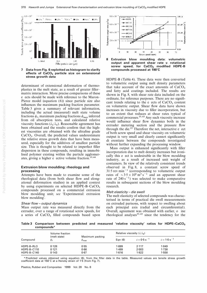
8 Extrusion blow moulding data: volumetricoutput and apparent shear rate v. rotationalscrew speed, for CaCO
3modified HDPE-B
6.0x10⁵
5.0x10⁵
4.0x10⁵
3.0x10⁵
2.0x10⁵
105
0
compounds processed at 190?C7 Data from Fig. 6 replotted as histogram to clarifyeffects of CaCO
3particle size on extensional
stress growth dataHDPE-B (Table 4). These data were then convertedto volumetric output using melt density parameters
determinant of extensional deformation of thermo- that take account of the exact amounts of CaCO3plastics in the melt state, as a result of greater filler– and fatty acid coatings included. The results arematrix interaction. More precise comparisons of these shown in Fig. 8, with shear rate data included on theeffects should be made with reference to the Maron– ordinate, for reference purposes. There are no signifi-Pierce model (equation (6)) since particle size also cant trends relating to the effects of CaCO3 contentinfluences the maximum packing fraction parameter. on volumetric output. Shear flow data have shownTable 3 gives a summary of relevant information, increases in viscosity due to filler incorporation, butincluding the actual (measured) melt state volume to an extent that reduces at shear rates typical offractions wf , maximum packing fractions wmax inferred commercial processes.35,43 Any such viscosity increasefrom oil absorption tests, and calculated relative would influence shear flow dynamics both in theviscosity functions (lf/l0 ). Reasonable agreement has extruder metering section and the pressure flowbeen obtained and the results confirm that the high- through the die.23 Therefore the net, interactive effectest viscosities are obtained with the ultrafine grade of both screw speed and shear viscosity on volumetricCaCO3 . Overall, the predicted values underestimate output is very small and clearly cannot significantlythe relative stress growth data that have been meas- differentiate between the compounds investigatedured, especially for the additives of smallest particle without further expanding the processing window.size. This is thought to be related to imperfect filler Mass output is enhanced significantly with fillerdispersion in these compounds, resulting in immobi- incorporation due to melt density increases but ironi-lised polymer existing within the particle agglomer- cally this effect is undesirable in the blow mouldingates, giving a higher effective volume fraction.19,44 industry, as a result of increased unit weight of
containers. In view of the relatively consistent trendsobserved in Fig. 8, a constant screw speed ofExtrusion blow moulding: rheology and
processing 31·5 rev min−1 (corresponding to volumetric outputrates of ~3·5×106 m3 s−1 and an apparent shearAttempts have been made to examine some of the
rheological data (from both shear flow and elong- rate of 240 s−1 ) was selected to make comparativeresults in subsequent sections of the blow mouldingational deformation studies) in an applied context
by using experiments on selected HDPE-B–CaCO3 research.compounds processed on a commercial extrusion Melt elasticity – die swellblow moulding unit; see ‘Experimental: extrusion
The melt elasticity of selected compounds was charac-blow moulding’.
terised in terms of practical die swell measurementson extruded parisons, with respect to swelling aboutShear flow – output dynamics
Mass output rate was measured directly from the each principal axis (radial and circumferential ).Overall, agreement was obtained with earlier, offlineextruder, over a range of rotational screw speeds, for
a series of CaCO3 filled compounds based upon rheological analyses35,43 since the tendency for the
Table 3 Comparison between predicted and measured ‘relative viscosity’ ratios for HDPE–CaCO3compounds*
Relative viscosity (l/l0)Volume fraction
(melt state) Maximum packingCompound w
fw
maxEqn (6) e=0·5 s−1 e=1·0 s−1
HDPE-B–RLO 0·128 0·55 1·699 2·117 1·849HDPE-B–C110 0·121 0·66 1·499 2·003 1·738HDPE-B–C140 0·143 0·67 1·616 1·822 1·558
* Predicted values obtained using equation (6), from the filler data in the table. Measured values are tensile stress growthcoefficient data at 150°C at a Hencky strain of 1·5 (from Fig. 7).
Plastics, Rubber and Composites 1999 Vol. 28 No. 8
Pub
lishe
d by
Man
ey P
ublis
hing
(c)
IOM
Com
mun
icat
ions
Ltd
Haworth and Jumpa Extensional flow characterisation and extrusion blow moulding of CaCO3
modified HDPE 371
(a)
(b)
(a)
(b)
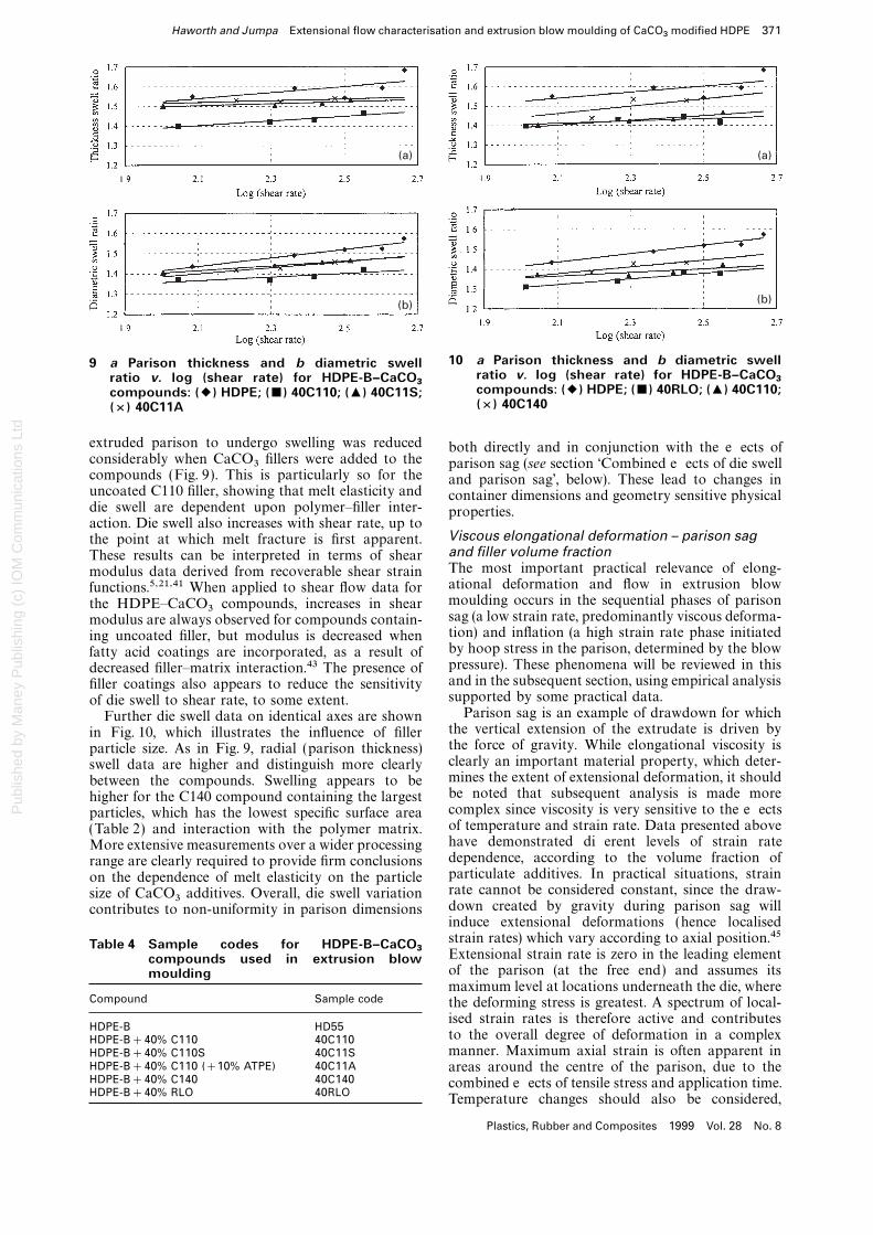
10 a Parison thickness and b diametric swell9 a Parison thickness and b diametric swellratio v. log (shear rate) for HDPE-B–CaCO
3ratio v. log (shear rate) for HDPE-B–CaCO3 compounds: (2) HDPE; (&) 40RLO; (+) 40C110;compounds: (2) HDPE; (&) 40C110; (+) 40C11S;
(×) 40C140(×) 40C11A
extruded parison to undergo swelling was reduced both directly and in conjunction with the effects ofconsiderably when CaCO3 fillers were added to the parison sag (see section ‘Combined effects of die swellcompounds (Fig. 9). This is particularly so for the and parison sag’, below). These lead to changes inuncoated C110 filler, showing that melt elasticity and container dimensions and geometry sensitive physicaldie swell are dependent upon polymer–filler inter- properties.action. Die swell also increases with shear rate, up to
Viscous elongational deformation – parison sagthe point at which melt fracture is first apparent.and filler volume fractionThese results can be interpreted in terms of shearThe most important practical relevance of elong-modulus data derived from recoverable shear strainational deformation and flow in extrusion blowfunctions.5,21,41 When applied to shear flow data formoulding occurs in the sequential phases of parisonthe HDPE–CaCO3 compounds, increases in shearsag (a low strain rate, predominantly viscous deforma-modulus are always observed for compounds contain-tion) and inflation (a high strain rate phase initiateding uncoated filler, but modulus is decreased whenby hoop stress in the parison, determined by the blowfatty acid coatings are incorporated, as a result ofpressure). These phenomena will be reviewed in thisdecreased filler–matrix interaction.43 The presence ofand in the subsequent section, using empirical analysisfiller coatings also appears to reduce the sensitivitysupported by some practical data.of die swell to shear rate, to some extent.
Parison sag is an example of drawdown for whichFurther die swell data on identical axes are shownthe vertical extension of the extrudate is driven byin Fig. 10, which illustrates the influence of fillerthe force of gravity. While elongational viscosity isparticle size. As in Fig. 9, radial (parison thickness)clearly an important material property, which deter-swell data are higher and distinguish more clearlymines the extent of extensional deformation, it shouldbetween the compounds. Swelling appears to bebe noted that subsequent analysis is made morehigher for the C140 compound containing the largestcomplex since viscosity is very sensitive to the effectsparticles, which has the lowest specific surface areaof temperature and strain rate. Data presented above(Table 2) and interaction with the polymer matrix.have demonstrated different levels of strain rateMore extensive measurements over a wider processingdependence, according to the volume fraction ofrange are clearly required to provide firm conclusionsparticulate additives. In practical situations, strainon the dependence of melt elasticity on the particlerate cannot be considered constant, since the draw-size of CaCO3 additives. Overall, die swell variationdown created by gravity during parison sag willcontributes to non-uniformity in parison dimensionsinduce extensional deformations (hence localisedstrain rates) which vary according to axial position.45Table 4 Sample codes for HDPE-B–CaCO
3 Extensional strain rate is zero in the leading elementcompounds used in extrusion blowof the parison (at the free end) and assumes itsmouldingmaximum level at locations underneath the die, where
Compound Sample code the deforming stress is greatest. A spectrum of local-ised strain rates is therefore active and contributes
HDPE-B HD55to the overall degree of deformation in a complexHDPE-B+40% C110 40C110manner. Maximum axial strain is often apparent inHDPE-B+40% C110S 40C11S
HDPE-B+40% C110 (+10% ATPE) 40C11A areas around the centre of the parison, due to theHDPE-B+40% C140 40C140 combined effects of tensile stress and application time.HDPE-B+40% RLO 40RLO
Temperature changes should also be considered,
Plastics, Rubber and Composites 1999 Vol. 28 No. 8
Pub
lishe
d by
Man
ey P
ublis
hing
(c)
IOM
Com
mun
icat
ions
Ltd
372 Haworth and Jumpa Extensional flow characterisation and extrusion blow moulding of CaCO3
modified HDPE
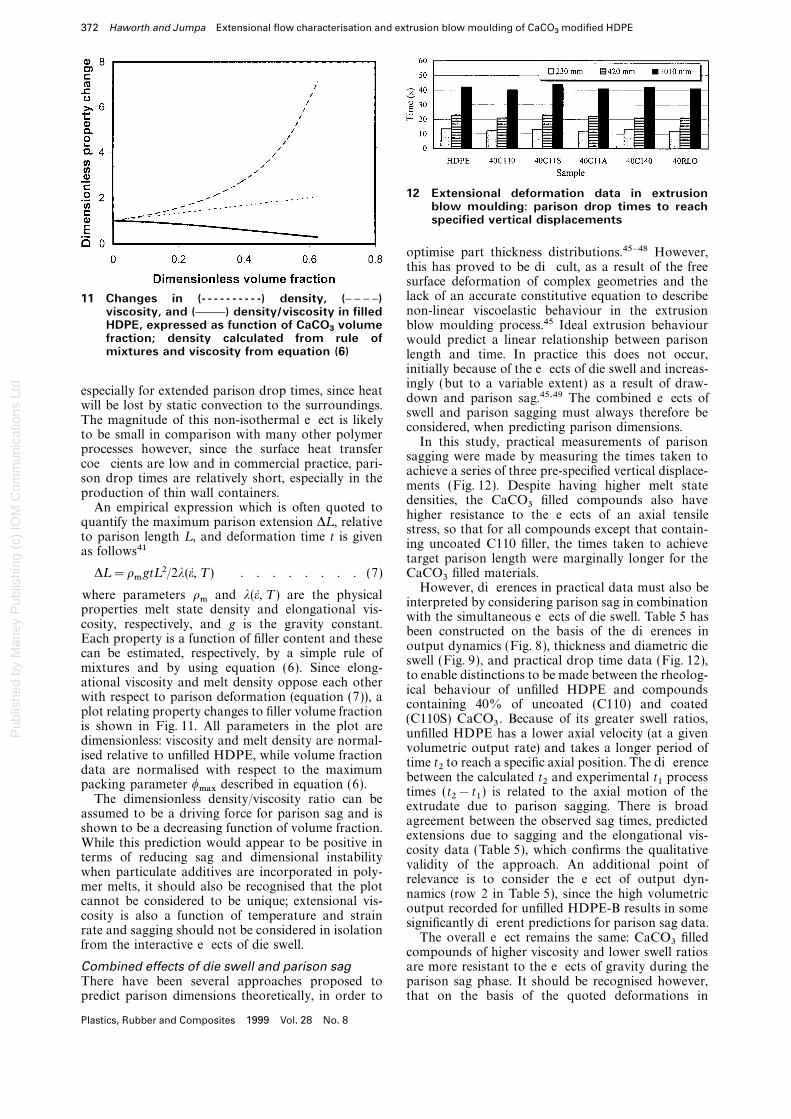
12 Extensional deformation data in extrusionblow moulding: parison drop times to reachspecified vertical displacements
optimise part thickness distributions.45–48 However,this has proved to be difficult, as a result of the freesurface deformation of complex geometries and thelack of an accurate constitutive equation to describe11 Changes in (- - - - - - - - - -) density, (D D D D)non-linear viscoelastic behaviour in the extrusionviscosity, and (CCD) density/viscosity in filled
HDPE, expressed as function of CaCO3
volume blow moulding process.45 Ideal extrusion behaviourfraction; density calculated from rule of would predict a linear relationship between parisonmixtures and viscosity from equation (6) length and time. In practice this does not occur,
initially because of the effects of die swell and increas-ingly (but to a variable extent) as a result of draw-
especially for extended parison drop times, since heatdown and parison sag.45,49 The combined effects of
will be lost by static convection to the surroundings.swell and parison sagging must always therefore be
The magnitude of this non-isothermal effect is likelyconsidered, when predicting parison dimensions.
to be small in comparison with many other polymerIn this study, practical measurements of parison
processes however, since the surface heat transfersagging were made by measuring the times taken to
coefficients are low and in commercial practice, pari-achieve a series of three pre-specified vertical displace-
son drop times are relatively short, especially in thements (Fig. 12). Despite having higher melt state
production of thin wall containers.densities, the CaCO3 filled compounds also have
An empirical expression which is often quoted tohigher resistance to the effects of an axial tensile
quantify the maximum parison extension DL , relativestress, so that for all compounds except that contain-
to parison length L , and deformation time t is givening uncoated C110 filler, the times taken to achieve
as follows41target parison length were marginally longer for theCaCO3 filled materials.DL =rmgtL 2/2l(e, T ) . . . . . . . . (7)
However, differences in practical data must also bewhere parameters rm and l(e, T ) are the physical
interpreted by considering parison sag in combinationproperties melt state density and elongational vis-
with the simultaneous effects of die swell. Table 5 hascosity, respectively, and g is the gravity constant.
been constructed on the basis of the differences inEach property is a function of filler content and these
output dynamics (Fig. 8), thickness and diametric diecan be estimated, respectively, by a simple rule of
swell (Fig. 9), and practical drop time data (Fig. 12),mixtures and by using equation (6). Since elong-
to enable distinctions to be made between the rheolog-ational viscosity and melt density oppose each other
ical behaviour of unfilled HDPE and compoundswith respect to parison deformation (equation (7)), a
containing 40% of uncoated (C110) and coatedplot relating property changes to filler volume fraction
(C110S) CaCO3 . Because of its greater swell ratios,is shown in Fig. 11. All parameters in the plot are
unfilled HDPE has a lower axial velocity (at a givendimensionless: viscosity and melt density are normal-
volumetric output rate) and takes a longer period ofised relative to unfilled HDPE, while volume fraction
time t2 to reach a specific axial position. The differencedata are normalised with respect to the maximum
between the calculated t2 and experimental t1 processpacking parameter wmax described in equation (6).
times (t2−t1 ) is related to the axial motion of theThe dimensionless density/viscosity ratio can be
extrudate due to parison sagging. There is broadassumed to be a driving force for parison sag and is
agreement between the observed sag times, predictedshown to be a decreasing function of volume fraction.
extensions due to sagging and the elongational vis-While this prediction would appear to be positive in
cosity data (Table 5), which confirms the qualitativeterms of reducing sag and dimensional instability
validity of the approach. An additional point ofwhen particulate additives are incorporated in poly-
relevance is to consider the effect of output dyn-mer melts, it should also be recognised that the plot
namics (row 2 in Table 5), since the high volumetriccannot be considered to be unique; extensional vis-
output recorded for unfilled HDPE-B results in somecosity is also a function of temperature and strain
significantly different predictions for parison sag data.rate and sagging should not be considered in isolation
The overall effect remains the same: CaCO3 filledfrom the interactive effects of die swell.
compounds of higher viscosity and lower swell ratiosare more resistant to the effects of gravity during theCombined effects of die swell and parison sag
There have been several approaches proposed to parison sag phase. It should be recognised however,that on the basis of the quoted deformations inpredict parison dimensions theoretically, in order to
Plastics, Rubber and Composites 1999 Vol. 28 No. 8
Pub
lishe
d by
Man
ey P
ublis
hing
(c)
IOM
Com
mun
icat
ions
Ltd
Haworth and Jumpa Extensional flow characterisation and extrusion blow moulding of CaCO3
modified HDPE 373
Table 5, the calculated elongational strain rates forparison sagging were in the range 1·2×10−3(HDPE–C110S) to 4·6×10−3 s−1 (unfilled HDPE),well below the experimental range over which vis-cosity and stress growth data were determined fromthe RER.
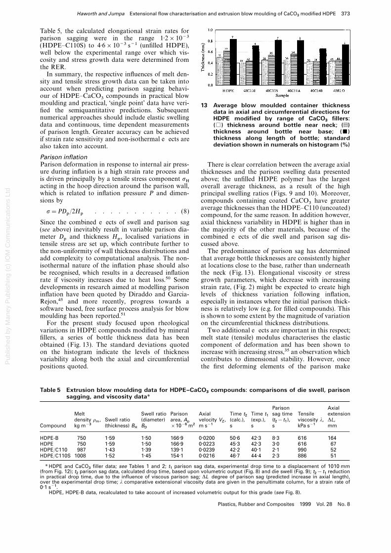
In summary, the respective influences of melt den-sity and tensile stress growth data can be taken intoaccount when predicting parison sagging behavi-our of HDPE–CaCO3 compounds in practical blowmoulding and practical, ‘single point’ data have veri- 13 Average blow moulded container thicknessfied the semiquantitative predictions. Subsequent data in axial and circumferential directions fornumerical approaches should include elastic swelling HDPE modified by range of CaCO
3fillers:
data and continuous, time dependent measurements (%) thickness around bottle near neck; (g)thickness around bottle near base; (&)of parison length. Greater accuracy can be achievedthickness along length of bottle; standardif strain rate sensitivity and non-isothermal effects aredeviation shown in numerals on histogram (%)also taken into account.
Parison inflationParison deformation in response to internal air press- There is clear correlation between the average axialure during inflation is a high strain rate process and thicknesses and the parison swelling data presentedis driven principally by a tensile stress component sH above; the unfilled HDPE polymer has the largestacting in the hoop direction around the parison wall, overall average thickness, as a result of the highwhich is related to inflation pressure P and dimen- principal swelling ratios (Figs. 9 and 10). Moreover,sions by compounds containing coated CaCO3 have greater
average thicknesses than the HDPE–C110 (uncoated)s=PDp/2Hp . . . . . . . . . . . (8)
compound, for the same reason. In addition however,axial thickness variability in HDPE is higher than inSince the combined effects of swell and parison sag
(see above) inevitably result in variable parison dia- the majority of the other materials, because of thecombined effects of die swell and parison sag dis-meter Dp and thickness Hp , localised variations in
tensile stress are set up, which contribute further to cussed above.The predominance of parison sag has determinedthe non-uniformity of wall thickness distributions and
add complexity to computational analysis. The non- that average bottle thicknesses are consistently higherat locations close to the base, rather than underneathisothermal nature of the inflation phase should also
be recognised, which results in a decreased inflation the neck (Fig. 13). Elongational viscosity or stressgrowth parameters, which decrease with increasingrate if viscosity increases due to heat loss.50 Some
developments in research aimed at modelling parison strain rate, (Fig. 2) might be expected to create highlevels of thickness variation following inflation,inflation have been quoted by Diraddo and Garcia-
Rejon,45 and more recently, progress towards a especially in instances where the initial parison thick-ness is relatively low (e.g. for filled compounds). Thissoftware based, free surface process analysis for blow
moulding has been reported.51 is shown to some extent by the magnitude of variationon the circumferential thickness distributions.For the present study focused upon rheological
variations in HDPE compounds modified by mineral Two additional effects are important in this respect;melt state (tensile) modulus characterises the elasticfillers, a series of bottle thickness data has been
obtained (Fig. 13). The standard deviations quoted component of deformation and has been shown toincrease with increasing stress,35 an observation whichon the histogram indicate the levels of thickness
variability along both the axial and circumferential contributes to dimensional stability. However, oncethe first deforming elements of the parison makepositions quoted.
Table 5 Extrusion blow moulding data for HDPE–CaCO3
compounds: comparisons of die swell, parisonsagging, and viscosity data*
Parison AxialMelt Swell ratio Parison Axial Time t
2Time t
1sag time Tensile extension
density rm
, Swell ratio (diameter) area, Ap
velocity VZ, (calc.), (exp.), (t
2−t
1), viscosity l, DL,
Compound kg m−3 (thickness) BH
BD
×10−6 m2 m s−1 s s s kPa s−1 mm
HDPE-B 750 1·59 1·50 166·9 0·0200 50·6 42·3 8·3 616 164HDPE† 750 1·59 1·50 166·9 0·0223 45·3 42·3 3·0 616 67HDPE/C110 987 1·43 1·39 139·1 0·0239 42·2 40·1 2·1 990 52HDPE/C110S 1008 1·52 1·45 154·1 0·0216 46·7 44·4 2·3 886 51
* HDPE and CaCO3
filler data; see Tables 1 and 2; t1
parison sag data, experimental drop time to a displacement of 1010 mm(from Fig. 12); t
2parison sag data, calculated drop time, based upon volumetric output (Fig. 8) and die swell (Fig. 9); t
2−t
1reduction
in practical drop time, due to the influence of viscous parison sag; DL degree of parison sag (predicted increase in axial length),over the experimental drop time; l comparative extensional viscosity data are given in the penultimate column, for a strain rate of0·1 s−1.
† HDPE, HDPE-B data, recalculated to take account of increased volumetric output for this grade (see Fig. 8).
Plastics, Rubber and Composites 1999 Vol. 28 No. 8
Pub
lishe
d by
Man
ey P
ublis
hing
(c)
IOM
Com
mun
icat
ions
Ltd
374 Haworth and Jumpa Extensional flow characterisation and extrusion blow moulding of CaCO3
modified HDPE
contact with the long face of an elliptical mould,thermal contact is made and the unconstrainedelements would be expected to deform preferentially(and at a higher localised strain rate), thereby produc-ing non-uniform dimensions around the containerperimeter. Since the CaCO3 filled compounds loseheat more rapidly, this non-uniformity would beespecially evident.
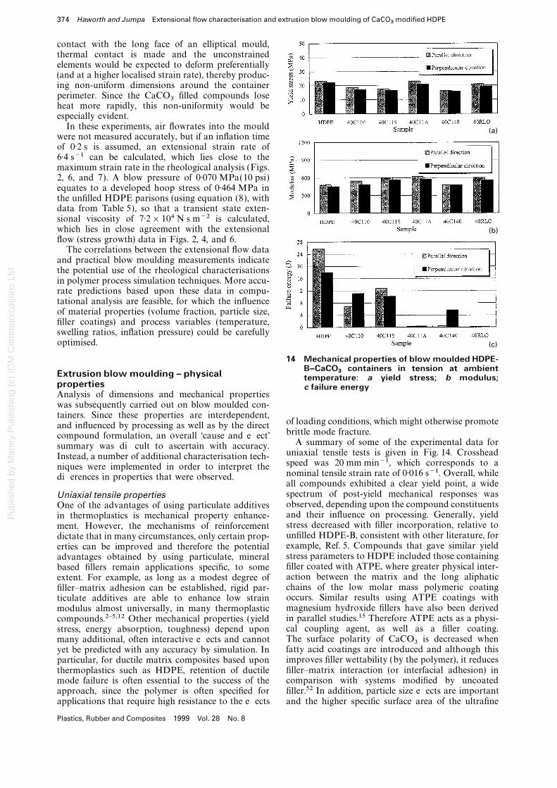
In these experiments, air flowrates into the mouldwere not measured accurately, but if an inflation timeof 0·2 s is assumed, an extensional strain rate of6·4 s−1 can be calculated, which lies close to themaximum strain rate in the rheological analysis (Figs.2, 6, and 7). A blow pressure of 0·070 MPa(10 psi)equates to a developed hoop stress of 0·464 MPa inthe unfilled HDPE parisons (using equation (8), withdata from Table 5), so that a transient state exten-sional viscosity of 7·2×104 N s m−2 is calculated,which lies in close agreement with the extensionalflow (stress growth) data in Figs. 2, 4, and 6.
The correlations between the extensional flow dataand practical blow moulding measurements indicatethe potential use of the rheological characterisationsin polymer process simulation techniques. More accu-rate predictions based upon these data in compu-tational analysis are feasible, for which the influenceof material properties (volume fraction, particle size,filler coatings) and process variables (temperature,swelling ratios, inflation pressure) could be carefullyoptimised.
(a)
(b)
(c)
14 Mechanical properties of blow moulded HDPE-B–CaCO
3containers in tension at ambient
Extrusion blow moulding – physical temperature: a yield stress; b modulus;properties c failure energyAnalysis of dimensions and mechanical propertieswas subsequently carried out on blow moulded con-tainers. Since these properties are interdependent,
of loading conditions, which might otherwise promoteand influenced by processing as well as by the directbrittle mode fracture.compound formulation, an overall ‘cause and effect’
A summary of some of the experimental data forsummary was difficult to ascertain with accuracy.uniaxial tensile tests is given in Fig. 14. CrossheadInstead, a number of additional characterisation tech-speed was 20 mm min−1, which corresponds to aniques were implemented in order to interpret thenominal tensile strain rate of 0·016 s−1. Overall, whiledifferences in properties that were observed.all compounds exhibited a clear yield point, a widespectrum of post-yield mechanical responses wasUniaxial tensile propertiesobserved, depending upon the compound constituentsOne of the advantages of using particulate additivesand their influence on processing. Generally, yieldin thermoplastics is mechanical property enhance-stress decreased with filler incorporation, relative toment. However, the mechanisms of reinforcementunfilled HDPE-B, consistent with other literature, fordictate that in many circumstances, only certain prop-example, Ref. 5. Compounds that gave similar yielderties can be improved and therefore the potentialstress parameters to HDPE included those containingadvantages obtained by using particulate, mineralfiller coated with ATPE, where greater physical inter-based fillers remain applications specific, to someaction between the matrix and the long aliphaticextent. For example, as long as a modest degree ofchains of the low molar mass polymeric coatingfiller–matrix adhesion can be established, rigid par-occurs. Similar results using ATPE coatings withticulate additives are able to enhance low strainmagnesium hydroxide fillers have also been derivedmodulus almost universally, in many thermoplasticin parallel studies.15 Therefore ATPE acts as a physi-compounds.2–5,12 Other mechanical properties (yieldcal coupling agent, as well as a filler coating.stress, energy absorption, toughness) depend uponThe surface polarity of CaCO3 is decreased whenmany additional, often interactive effects and cannotfatty acid coatings are introduced and although thisyet be predicted with any accuracy by simulation. Inimproves filler wettability (by the polymer), it reducesparticular, for ductile matrix composites based uponfiller–matrix interaction (or interfacial adhesion) inthermoplastics such as HDPE, retention of ductilecomparison with systems modified by uncoatedmode failure is often essential to the success of thefiller.52 In addition, particle size effects are importantapproach, since the polymer is often specified for
applications that require high resistance to the effects and the higher specific surface area of the ultrafine
Plastics, Rubber and Composites 1999 Vol. 28 No. 8
Pub
lishe
d by
Man
ey P
ublis
hing
(c)
IOM
Com
mun
icat
ions
Ltd
Haworth and Jumpa Extensional flow characterisation and extrusion blow moulding of CaCO3
modified HDPE 375
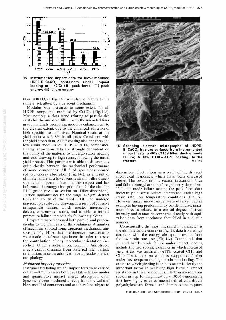
15 Instrumented impact data for blow mouldedHDPE-B–CaCO
3containers under impact
loading at −40?C: (&) peak force; (%) peakenergy; (g) failure energy
filler (40RLO, in Fig. 14a) will also contribute to thesame effect, albeit by a different mechanism.
Modulus was increased to some extent for allHDPE compounds modified by CaCO3 (Fig. 14b).Most notably, a clear trend relating to particle sizeexists for the uncoated fillers, with the uncoated finergrade materials promoting modulus enhancement tothe greatest extent, due to the enhanced adhesion ofhigh specific area additives. Nominal strain at theyield point was 6–8% in all cases. Consistent withthe yield stress data, ATPE coating also enhances the
a
b
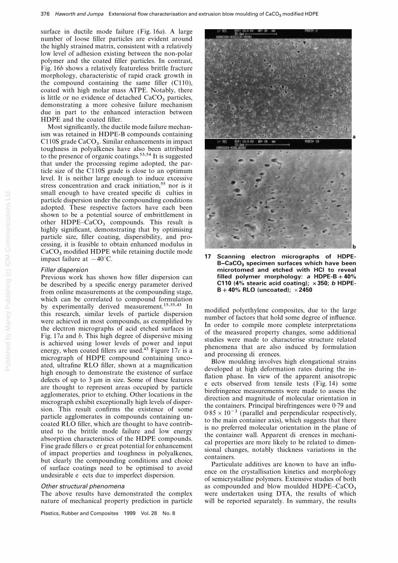
low strain modulus of HDPE–CaCO3 composites. 16 Scanning electron micrographs of HDPE-Energy absorption data are strongly dependent on B–CaCO
3fracture surfaces from instrumented
impact tests: a 40% C110S filler, ductile modethe ability of the material to undergo stable neckingfailure; b 40% C110+ATPE coating, brittleand cold drawing to high strain, following the initialfracture ×1050yield process. This parameter is able to differentiate
quite clearly between the mechanical performanceof some compounds. All filled specimens showed
dimensional fluctuations as a result of the differentreduced energy absorption (Fig. 14c), as a result of
rheological responses, which have been discussedultimate failure at a lower tensile strain. Filler disper-
above. The results in this section (maximum forcesion is an important factor in this respect and has
and failure energy) are therefore geometry dependent.influenced the energy absorption data for the ultrafine
If ductile mode failure occurs, the peak force dataRLO grade (see also section on ‘Filler dispersion’).
indicate yield stress values determined under highParticle agglomerates (in the range 1–5 mm) detract
strain rate, low temperature conditions (Fig. 15).from the ability of the filled HDPE to undergo
However, mixed mode failures were observed and inmacroscopic scale cold drawing as a result of cohesive
examples having predominantly brittle failures, maxi-intraparticle failure, which creates microscopic
mum force is related to a critical degree of stressdefects, concentrates stress, and is able to initiate
intensity and cannot be compared directly with equi-premature failure immediately following yielding.
valent data from specimens that failed in a ductileProperties were measured both parallel and perpen-
manner.dicular to the main axis of the containers. A number
Consequently, the most meaningful parameter isof specimens showed some apparent mechanical ani-
the ultimate failure energy in Fig. 15, data from whichsotropy (Fig. 14) so that birefringence measurements
correlate with the energy absorption results fromwere made on selected specimens in order to assess
the low strain rate tests (Fig. 14c). Compounds thatthe contribution of any molecular orientation (see
suffered brittle mode failure under impact loadingsection ‘Other structural phenomena’). Anisotropic
include the two specific examples in which increasedeffects cannot originate from preferred filler particle
yield stress was apparent (ATPE coated C110 andorientation, since the additives have a pseudospherical
C140 fillers), an effect which is exaggerated furthermorphology.
under low temperature, high strain rate loading. Theextent to which yielding is able to occur is clearly theMultiaxial impact properties
Instrumented falling weight impact tests were carried important factor in achieving high levels of impactresistance in these compounds. Electron micrographsout at −40°C to assess both qualitative failure modes
and quantitative impact energy absorption data. shown in Fig. 16 (magnification×1050) demonstratefirst how highly oriented microfibrils of cold drawnSpecimens were machined directly from the walls of
blow moulded containers and are therefore subject to polyethylene are formed and dominate the rupture
Plastics, Rubber and Composites 1999 Vol. 28 No. 8
Pub
lishe
d by
Man
ey P
ublis
hing
(c)
IOM
Com
mun
icat
ions
Ltd
376 Haworth and Jumpa Extensional flow characterisation and extrusion blow moulding of CaCO3
modified HDPE
surface in ductile mode failure (Fig. 16a). A largenumber of loose filler particles are evident aroundthe highly strained matrix, consistent with a relativelylow level of adhesion existing between the non-polarpolymer and the coated filler particles. In contrast,Fig. 16b shows a relatively featureless brittle fracturemorphology, characteristic of rapid crack growth inthe compound containing the same filler (C110),coated with high molar mass ATPE. Notably, thereis little or no evidence of detached CaCO3 particles,demonstrating a more cohesive failure mechanismdue in part to the enhanced interaction betweenHDPE and the coated filler.
Most significantly, the ductile mode failure mechan-ism was retained in HDPE-B compounds containingC110S grade CaCO3 . Similar enhancements in impacttoughness in polyalkenes have also been attributedto the presence of organic coatings.53,54 It is suggestedthat under the processing regime adopted, the par-ticle size of the C110S grade is close to an optimumlevel. It is neither large enough to induce excessivestress concentration and crack initiation,55 nor is itsmall enough to have created specific difficulties inparticle dispersion under the compounding conditionsadopted. These respective factors have each beenshown to be a potential source of embrittlement inother HDPE–CaCO3 compounds. This result ishighly significant, demonstrating that by optimisingparticle size, filler coating, dispersibility, and pro-cessing, it is feasible to obtain enhanced modulus in
a
bCaCO3 modified HDPE while retaining ductile mode
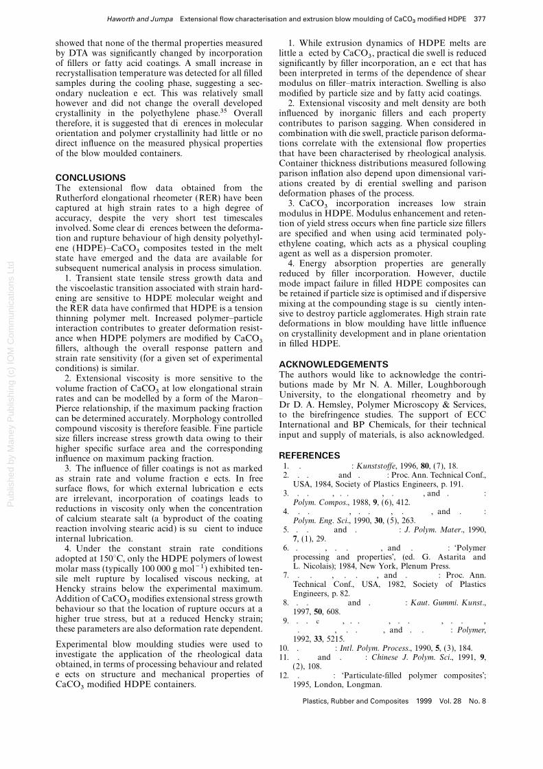
17 Scanning electron micrographs of HDPE-impact failure at −40°C.B–CaCO
3specimen surfaces which have been
microtomed and etched with HCl to revealFiller dispersionfilled polymer morphology: a HDPE-B+40%Previous work has shown how filler dispersion canC110 (4% stearic acid coating); ×350; b HDPE-be described by a specific energy parameter derivedB+40% RLO (uncoated); ×2450from online measurements at the compounding stage,
which can be correlated to compound formulationby experimentally derived measurement.15,35,43 In
modified polyethylene composites, due to the largethis research, similar levels of particle dispersion
number of factors that hold some degree of influence.were achieved in most compounds, as exemplified by
In order to compile more complete interpretationsthe electron micrographs of acid etched surfaces in
of the measured property changes, some additionalFig. 17a and b. This high degree of dispersive mixing
studies were made to characterise structure relatedis achieved using lower levels of power and input
phenomena that are also induced by formulationenergy, when coated fillers are used.43 Figure 17c is a
and processing differences.micrograph of HDPE compound containing unco-
Blow moulding involves high elongational strainsated, ultrafine RLO filler, shown at a magnification
developed at high deformation rates during the in-high enough to demonstrate the existence of surface
flation phase. In view of the apparent anisotropicdefects of up to 3 mm in size. Some of these features
effects observed from tensile tests (Fig. 14) someare thought to represent areas occupied by particle
birefringence measurements were made to assess theagglomerates, prior to etching. Other locations in the
direction and magnitude of molecular orientation inmicrograph exhibit exceptionally high levels of disper-
the containers. Principal birefringences were 0·79 andsion. This result confirms the existence of some
0·85×10−3 (parallel and perpendicular respectively,particle agglomerates in compounds containing un-
to the main container axis), which suggests that therecoated RLO filler, which are thought to have contrib-
is no preferred molecular orientation in the plane ofuted to the brittle mode failure and low energy
the container wall. Apparent differences in mechani-absorption characteristics of the HDPE compounds.
cal properties are more likely to be related to dimen-Fine grade fillers offer great potential for enhancement
sional changes, notably thickness variations in theof impact properties and toughness in polyalkenes,
containers.but clearly the compounding conditions and choice
Particulate additives are known to have an influ-of surface coatings need to be optimised to avoid
ence on the crystallisation kinetics and morphologyundesirable effects due to imperfect dispersion.
of semicrystalline polymers. Extensive studies of bothas compounded and blow moulded HDPE–CaCO3Other structural phenomena
The above results have demonstrated the complex were undertaken using DTA, the results of whichwill be reported separately. In summary, the resultsnature of mechanical property prediction in particle
Plastics, Rubber and Composites 1999 Vol. 28 No. 8
Pub
lishe
d by
Man
ey P
ublis
hing
(c)
IOM
Com
mun
icat
ions
Ltd
Haworth and Jumpa Extensional flow characterisation and extrusion blow moulding of CaCO3
modified HDPE 377
showed that none of the thermal properties measured 1. While extrusion dynamics of HDPE melts arelittle affected by CaCO3 , practical die swell is reducedby DTA was significantly changed by incorporation
of fillers or fatty acid coatings. A small increase in significantly by filler incorporation, an effect that hasbeen interpreted in terms of the dependence of shearrecrystallisation temperature was detected for all filled
samples during the cooling phase, suggesting a sec- modulus on filler–matrix interaction. Swelling is alsomodified by particle size and by fatty acid coatings.ondary nucleation effect. This was relatively small
however and did not change the overall developed 2. Extensional viscosity and melt density are bothinfluenced by inorganic fillers and each propertycrystallinity in the polyethylene phase.35 Overall
therefore, it is suggested that differences in molecular contributes to parison sagging. When considered incombination with die swell, practicle parison deforma-orientation and polymer crystallinity had little or no
direct influence on the measured physical properties tions correlate with the extensional flow propertiesthat have been characterised by rheological analysis.of the blow moulded containers.Container thickness distributions measured followingparison inflation also depend upon dimensional vari-CONCLUSIONSations created by differential swelling and parison
The extensional flow data obtained from thedeformation phases of the process.
Rutherford elongational rheometer (RER) have been3. CaCO3 incorporation increases low strain
captured at high strain rates to a high degree ofmodulus in HDPE. Modulus enhancement and reten-
accuracy, despite the very short test timescalestion of yield stress occurs when fine particle size fillers
involved. Some clear differences between the deforma-are specified and when using acid terminated poly-
tion and rupture behaviour of high density polyethyl-ethylene coating, which acts as a physical coupling
ene (HDPE)–CaCO3 composites tested in the meltagent as well as a dispersion promoter.
state have emerged and the data are available for4. Energy absorption properties are generally
subsequent numerical analysis in process simulation.reduced by filler incorporation. However, ductile
1. Transient state tensile stress growth data andmode impact failure in filled HDPE composites can
the viscoelastic transition associated with strain hard-be retained if particle size is optimised and if dispersive
ening are sensitive to HDPE molecular weight andmixing at the compounding stage is sufficiently inten-
the RER data have confirmed that HDPE is a tensionsive to destroy particle agglomerates. High strain rate
thinning polymer melt. Increased polymer–particledeformations in blow moulding have little influence
interaction contributes to greater deformation resist-on crystallinity development and in plane orientation
ance when HDPE polymers are modified by CaCO3 in filled HDPE.fillers, although the overall response pattern andstrain rate sensitivity (for a given set of experimental
ACKNOWLEDGEMENTSconditions) is similar.The authors would like to acknowledge the contri-2. Extensional viscosity is more sensitive to thebutions made by Mr N. A. Miller, Loughboroughvolume fraction of CaCO3 at low elongational strainUniversity, to the elongational rheometry and byrates and can be modelled by a form of the Maron–Dr D. A. Hemsley, Polymer Microscopy & Services,Pierce relationship, if the maximum packing fractionto the birefringence studies. The support of ECCcan be determined accurately. Morphology controlledInternational and BP Chemicals, for their technicalcompound viscosity is therefore feasible. Fine particleinput and supply of materials, is also acknowledged.size fillers increase stress growth data owing to their
higher specific surface area and the correspondingREFERENCESinfluence on maximum packing fraction.1. . : KunststoVe, 1996, 80, (7), 18.3. The influence of filler coatings is not as marked2. . . and . : Proc. Ann. Technical Conf.,as strain rate and volume fraction effects. In free
USA, 1984, Society of Plastics Engineers, p. 191.surface flows, for which external lubrication effects
3. . . , . . , . , and . :are irrelevant, incorporation of coatings leads to Polym. Compos., 1988, 9, (6), 412.reductions in viscosity only when the concentration 4. . . , . . , . , and . :of calcium stearate salt (a byproduct of the coating Polym. Eng. Sci., 1990, 30, (5), 263.reaction involving stearic acid) is sufficient to induce 5. . . and . : J. Polym. Mater., 1990,
7, (1), 29.internal lubrication.6. . , . . , and . : ‘Polymer4. Under the constant strain rate conditions
processing and properties’, (ed. G. Astarita andadopted at 150°C, only the HDPE polymers of lowestL. Nicolais); 1984, New York, Plenum Press.molar mass (typically 100 000 g mol−1 ) exhibited ten-
7. . . , . . , and . : Proc. Ann.sile melt rupture by localised viscous necking, atTechnical Conf., USA, 1982, Society of Plastics
Hencky strains below the experimental maximum.Engineers, p. 82.
Addition of CaCO3 modifies extensional stress growth 8. . . and . : Kaut. Gummi. Kunst.,behaviour so that the location of rupture occurs at a 1997, 50, 608.higher true stress, but at a reduced Hencky strain; 9. . . c, . . , . . , . . ,these parameters are also deformation rate dependent. . , . . , and . . : Polymer,
1992, 33, 5215.Experimental blow moulding studies were used to 10. . : Intl. Polym. Process., 1990, 5, (3), 184.investigate the application of the rheological data 11. . and . : Chinese J. Polym. Sci., 1991, 9,obtained, in terms of processing behaviour and related (2), 108.effects on structure and mechanical properties of 12. . : ‘Particulate-filled polymer composites’;
1995, London, Longman.CaCO3 modified HDPE containers.
Plastics, Rubber and Composites 1999 Vol. 28 No. 8
Pub
lishe
d by
Man
ey P
ublis
hing
(c)
IOM
Com
mun
icat
ions
Ltd
378 Haworth and Jumpa Extensional flow characterisation and extrusion blow moulding of CaCO3
modified HDPE
13. . , . , and . : Eur. Polym. J., 34. . . : J. Rheol., 1995, 39, (1), 253.35. . : ‘Elongational rheometry and processing of1984, 20, (12), 1155.
filled polyethylene melts’, PhD thesis, Loughborough14. . : J. Mater. Sci., 1989, 24, 3947.University, UK, 1998.15. . . : ‘Coatings for magnesium hydroxide
36. . , . , and . : Proc. Int.fillers in polyethylene compounds’, PhD thesis, Lough-Conf. ‘PPS-15’, S’Hertogenbosch, The Netherlands,borough University, UK, 1997.1999, Polymer Processing Society, Paper 224.16. . : ‘Polymer additives’, (ed. J. E. Kresta); 1984,
37. . and . . : J. Appl. Polym. Sci., 1978, 22, 1061.New York, Plenum Press.38. . and . . : Rheol. Acta, 1981, 20, 211.17. . . : Proc. Engineering Properties and Structure39. . , . . , and . . : Polym.Division ‘Additives’, Divtec Hudson, OH, USA, 1975,
Eng. Sci., 1980, 20, (17), 1166.Society of Plastics Engineers.40. . . and . . . : J. Rheol., 1997, 41, (1), 1.18. . . ’, . . , . . ’, and41. . . : ‘Polymer melt rheology’, 2nd edn; 1994,. . : Int. Polym. Sci. T ech., 1988, 15, (6), 75.
Cambridge, Woodhead.19. . : ‘Mechanisms of extrudate swell and melt42. . and . : Polym. Eng. Sci., 1996, 36,fracture in SBR compounds’, PhD thesis, Lough-
(2), 237.borough University, UK, 1996.43. . , . , and . . : Proc. Int. Conf.20. . . and . : J. Mater. Sci., 1994,
‘PPS-15’, S’Hertogenbosch, The Netherlands, 1999,29, 5293.Polymer Processing Society, Paper 132.21. . and . . : J. Appl. Polym. Sci., 1983,
44. . and . . : Plast. Rubber. Compos.28, 1481.Process. Appl., 1997, 26, (3), 113.22. . . : ‘Rheometers for molten plastics’; 1982, New
45. . . and . -: Polym. Eng. Sci.,York, Van Nostrand.1992, 32, (19), 1401.
23. . . , . , and . : ‘Physics46. . and . . : J. Non-Newton. Fluid Mech.,
of plastics: processing, properties and materials engin-1982, 10, 235.
eering’; 1992, Munich, Hanser.47. . -, . , and . . : SPE T ech.
24. . . : T rans. Soc. Rheol., 1972, 16, (3), 383.Papers, 1981, 27, 431.
25. . : J. Rheol., 1979, 23, 421.48. . . and . : AIChE J., 1985, 31, 807.
26. . . : ‘A study of the extensional flow behaviour 49. . . and . : J. Sci. Soc. T hailand,of low density polyethylene’, PhD thesis, Loughborough 1993, 19, 25.University, UK, 1984. 50. . . , . , and . : Polym. Eng. Sci.,
27. . . : ‘A study of the flow properties and 1981, 21, (6), 331.processability of thermoplastic polyesters’, PhD thesis, 51. . and . : Presented at Conf. ‘AdvancesLoughborough University, UK, 1987. in blow moulding’, Loughborough, UK, June 1998,
28. . . and . : Plast. Rubber Compos. Institute of Materials.Process. Appl., 1994, 22, (3), 127. 52. . , . , and . : J. Mater. Sci.,
29. . , . . , and . : Plast. Rubber L ett., 1989, 8, 1040.Compos. Process. Appl., 1994, 22, (3), 159. 53. . . and . . : Proc. Int. Fillers Symp.,
30. . . and . . : Proc. Ann. Technical Loughborough, UK, 1994.Conf., USA, 1986, Society of Plastics Engineers, p. 679. 54. . and . . : J. Mater. Sci., 1993, 24, 6531.
31. . . and . : Polym. T est., 1990, 9, 53. 55. . . , . . , . . c, and32. . and . : Polym. T est., to be published. . . : Plast. Rubber Process. Appl., 1990, 14,
(2), 85.33. . : Polym. Eng. Sci., 1987, 27, (8), 537–546.
Plastics, Rubber and Composites 1999 Vol. 28 No. 8


