ETSI GR ENI 001 V1.1.1 (2018-04)
Experiential Networked Intelligence (ENI); ENI use cases
Disclaimer
The present document has been produced and approved by the Experiential Networked Intelligence (ENI) ETSI Industry Specification Group (ISG) and represents the views of those members who participated in this ISG.
It does not necessarily represent the views of the entire ETSI membership.
GROUP REPORT
ETSI
ETSI GR ENI 001 V1.1.1 (2018-04)2
Reference DGR/ENI-001
Keywords artificial intelligence, management, network,
use case
ETSI
650 Route des Lucioles F-06921 Sophia Antipolis Cedex - FRANCE
Tel.: +33 4 92 94 42 00 Fax: +33 4 93 65 47 16
Siret N° 348 623 562 00017 - NAF 742 C
Association à but non lucratif enregistrée à la Sous-Préfecture de Grasse (06) N° 7803/88
Important notice
The present document can be downloaded from: http://www.etsi.org/standards-search
The present document may be made available in electronic versions and/or in print. The content of any electronic and/or print versions of the present document shall not be modified without the prior written authorization of ETSI. In case of any
existing or perceived difference in contents between such versions and/or in print, the only prevailing document is the print of the Portable Document Format (PDF) version kept on a specific network drive within ETSI Secretariat.
Users of the present document should be aware that the document may be subject to revision or change of status. Information on the current status of this and other ETSI documents is available at
https://portal.etsi.org/TB/ETSIDeliverableStatus.aspx
If you find errors in the present document, please send your comment to one of the following services: https://portal.etsi.org/People/CommiteeSupportStaff.aspx
Copyright Notification
No part may be reproduced or utilized in any form or by any means, electronic or mechanical, including photocopying and microfilm except as authorized by written permission of ETSI.
The content of the PDF version shall not be modified without the written authorization of ETSI. The copyright and the foregoing restriction extend to reproduction in all media.
© ETSI 2018.
All rights reserved.
DECTTM, PLUGTESTSTM, UMTSTM and the ETSI logo are trademarks of ETSI registered for the benefit of its Members. 3GPPTM and LTETM are trademarks of ETSI registered for the benefit of its Members and
of the 3GPP Organizational Partners. oneM2M logo is protected for the benefit of its Members.
GSM® and the GSM logo are trademarks registered and owned by the GSM Association.
ETSI
ETSI GR ENI 001 V1.1.1 (2018-04)3
Contents
Intellectual Property Rights ................................................................................................................................ 6
Foreword ............................................................................................................................................................. 6
Modal verbs terminology .................................................................................................................................... 6
1 Scope ........................................................................................................................................................ 7
2 References ................................................................................................................................................ 7
2.1 Normative references ......................................................................................................................................... 7
2.2 Informative references ........................................................................................................................................ 7
3 Definitions and abbreviations ................................................................................................................... 7
3.1 Definitions .......................................................................................................................................................... 7
3.2 Abbreviations ..................................................................................................................................................... 8
4 Overview .................................................................................................................................................. 9
4.1 Background ........................................................................................................................................................ 9
4.2 Overview of the ENI System .............................................................................................................................. 9
4.2.1 Brief Description .......................................................................................................................................... 9
4.2.2 Expected Benefits ....................................................................................................................................... 10
5 General use cases ................................................................................................................................... 10
5.1 Introduction ...................................................................................................................................................... 10
5.2 Infrastructure Management .............................................................................................................................. 11
5.2.1 Use Case #1-1: Policy-driven IDC Traffic Steering ................................................................................... 11
5.2.1.1 Use case context .................................................................................................................................... 11
5.2.1.2 Description of the use case .................................................................................................................... 11
5.2.1.2.1 Overview ......................................................................................................................................... 11
5.2.1.2.2 Motivation ....................................................................................................................................... 12
5.2.1.2.3 Actors and Roles.............................................................................................................................. 13
5.2.1.2.4 Initial context configuration ............................................................................................................ 13
5.2.1.2.5 Trigger conditions ........................................................................................................................... 13
5.2.1.2.6 Operational Flow of the actions ....................................................................................................... 13
5.2.1.2.7 Post-conditions ................................................................................................................................ 14
5.2.2 Use Case #1-2: Handling of Peak Planned Occurrences............................................................................. 14
5.2.2.1 Use case context .................................................................................................................................... 14
5.2.2.2 Description of the use case .................................................................................................................... 14
5.2.2.2.1 Overview ......................................................................................................................................... 14
5.2.2.2.2 Motivation ....................................................................................................................................... 15
5.2.2.2.3 Actors and Roles.............................................................................................................................. 15
5.2.2.2.4 Initial context configuration ............................................................................................................ 15
5.2.2.2.5 Triggering conditions ...................................................................................................................... 15
5.2.2.2.6 Operational flow of actions ............................................................................................................. 15
5.2.2.2.7 Post-conditions ................................................................................................................................ 16
5.2.3 Use Case #1-3: Energy optimization using AI ............................................................................................ 16
5.2.3.1 Use case context .................................................................................................................................... 16
5.2.3.2 Description of the use case .................................................................................................................... 16
5.2.3.2.1 Overview ......................................................................................................................................... 16
5.2.3.2.2 Motivation ....................................................................................................................................... 17
5.2.3.2.3 Actors and Roles.............................................................................................................................. 17
5.2.3.2.4 Initial context configuration ............................................................................................................ 17
5.2.3.2.5 Triggering conditions ...................................................................................................................... 18
5.2.3.2.6 Operational flow of actions ............................................................................................................. 18
5.2.3.2.7 Post-conditions ................................................................................................................................ 18
5.3 Network Operations ......................................................................................................................................... 19
5.3.1 Use Case #2-1: Policy-driven IP managed networks .................................................................................. 19
5.3.1.1 Use case context .................................................................................................................................... 19
5.3.1.2 Description of the use case .................................................................................................................... 19
5.3.1.2.1 Overview ......................................................................................................................................... 19
5.3.1.2.2 Motivation ....................................................................................................................................... 19
ETSI
ETSI GR ENI 001 V1.1.1 (2018-04)4
5.3.1.2.3 Actors and Roles.............................................................................................................................. 20
5.3.1.2.4 Initial context configuration ............................................................................................................ 20
5.3.1.2.5 Triggering conditions ...................................................................................................................... 20
5.3.1.2.6 Operational flow of actions ............................................................................................................. 20
5.3.1.2.7 Post-conditions ................................................................................................................................ 21
5.3.2 Use Case #2-2: Radio Coverage and capacity optimization ....................................................................... 21
5.3.2.1 Use case context .................................................................................................................................... 21
5.3.2.2 Description of the use case .................................................................................................................... 21
5.3.2.2.1 Overview ......................................................................................................................................... 21
5.3.2.2.2 Motivation ....................................................................................................................................... 22
5.3.2.2.3 Actors and Roles.............................................................................................................................. 22
5.3.2.2.4 Initial context configuration ............................................................................................................ 22
5.3.2.2.5 Triggering conditions ...................................................................................................................... 22
5.3.2.2.6 Operational flow of actions ............................................................................................................. 22
5.3.2.2.7 Post-conditions ................................................................................................................................ 23
5.3.3 Use Case #2-3: Intelligent Software Rollouts ............................................................................................. 23
5.3.3.1 Use Case context ................................................................................................................................... 23
5.3.3.2 Description of the Use Case .................................................................................................................. 23
5.3.3.2.1 Overview ......................................................................................................................................... 23
5.3.3.2.2 Motivation ....................................................................................................................................... 23
5.3.3.2.3 Actors and Roles.............................................................................................................................. 24
5.3.3.2.4 Initial context configuration ............................................................................................................ 24
5.3.3.2.5 Triggering conditions ...................................................................................................................... 24
5.3.3.2.6 Operational flow of actions ............................................................................................................. 24
5.3.3.2.7 Post-conditions ................................................................................................................................ 25
5.3.4 Use Case #2-4: Policy-based network slicing for IoT security ................................................................... 25
5.3.4.1 Use Case context ................................................................................................................................... 25
5.3.4.2 Description of the Use Case .................................................................................................................. 26
5.3.4.2.1 Motivation ....................................................................................................................................... 26
5.3.4.2.2 Actors and Roles.............................................................................................................................. 26
5.3.4.2.3 Initial context configuration ............................................................................................................ 26
5.3.4.2.4 Triggering conditions ...................................................................................................................... 27
5.3.4.2.5 Operational flow of actions ............................................................................................................. 27
5.3.4.2.6 Post-conditions ................................................................................................................................ 27
5.3.5 Use Case #2-5: Intelligent Fronthaul Management and Orchestration ....................................................... 27
5.3.5.1 Use Case context ................................................................................................................................... 27
5.3.5.2 Description of the use case .................................................................................................................... 28
5.3.5.2.1 Overview ......................................................................................................................................... 28
5.3.5.2.2 Motivation ....................................................................................................................................... 28
5.3.5.2.3 Actors and Roles.............................................................................................................................. 29
5.3.5.2.4 Initial context configuration ............................................................................................................ 29
5.3.5.2.5 Triggering conditions ...................................................................................................................... 29
5.3.5.2.6 Operational flow of actions ............................................................................................................. 29
5.3.5.2.7 Post-conditions ................................................................................................................................ 29
5.4 Service Orchestration and Management ........................................................................................................... 29
5.4.1 Use Case #3-1: Context-aware VoLTE Service Experience Optimization ................................................. 29
5.4.1.1 Use case context .................................................................................................................................... 29
5.4.1.2 Description of the use case .................................................................................................................... 30
5.4.1.2.1 Overview ......................................................................................................................................... 30
5.4.1.2.2 Motivation ....................................................................................................................................... 30
5.4.1.2.3 Actors and Roles.............................................................................................................................. 30
5.4.1.2.4 Initial context configuration ............................................................................................................ 31
5.4.1.2.5 Triggering conditions ...................................................................................................................... 31
5.4.1.2.6 Operational flow of actions ............................................................................................................. 31
5.4.1.2.7 Post-conditions ................................................................................................................................ 31
5.4.2 Use Case #3-2: Intelligent network slicing management ............................................................................ 31
5.4.2.1 Use case context .................................................................................................................................... 31
5.4.2.2 Description of the use case .................................................................................................................... 31
5.4.2.2.1 Overview ......................................................................................................................................... 31
5.4.2.2.2 Motivation ....................................................................................................................................... 32
5.4.2.2.3 Actors and Roles.............................................................................................................................. 32
5.4.2.2.4 Initial context configuration ............................................................................................................ 33
ETSI
ETSI GR ENI 001 V1.1.1 (2018-04)5
5.4.2.2.5 Triggering conditions ...................................................................................................................... 33
5.4.2.2.6 Operational flow of actions ............................................................................................................. 33
5.4.2.2.7 Post-conditions ................................................................................................................................ 33
5.4.3 Use Case #3-3: Intelligent carrier-managed SD-WAN ............................................................................... 33
5.4.3.1 Use case context .................................................................................................................................... 33
5.4.3.2 Description of the use case .................................................................................................................... 34
5.4.3.2.1 Overview ......................................................................................................................................... 34
5.4.3.2.2 Motivation ....................................................................................................................................... 34
5.4.3.2.3 Actors and Roles.............................................................................................................................. 35
5.4.3.2.4 Initial context configuration ............................................................................................................ 35
5.4.3.2.5 Triggering conditions ...................................................................................................................... 35
5.4.3.2.6 Operational flow of actions ............................................................................................................. 35
5.4.3.2.7 Post-conditions ................................................................................................................................ 36
5.5 Assurance ......................................................................................................................................................... 36
5.5.1 Use Case #4-1: Network fault identification and prediction ....................................................................... 36
5.5.1.1 Use case context .................................................................................................................................... 36
5.5.1.2 Description of the use case .................................................................................................................... 36
5.5.1.2.1 Overview ......................................................................................................................................... 36
5.5.1.2.2 Motivation ....................................................................................................................................... 37
5.5.1.2.3 Actors and Roles.............................................................................................................................. 37
5.5.1.2.4 Initial context configuration ............................................................................................................ 37
5.5.1.2.5 Triggering conditions ...................................................................................................................... 37
5.5.1.2.6 Operational flow of actions ............................................................................................................. 37
5.5.1.2.7 Post-conditions ................................................................................................................................ 37
5.5.2 Use Case #4-2: Assurance of Service Requirements .................................................................................. 38
5.5.2.1 Use Case context ................................................................................................................................... 38
5.5.2.2 Description of the Use Case .................................................................................................................. 38
5.5.2.2.1 Overview ......................................................................................................................................... 38
5.5.2.2.2 Motivation ....................................................................................................................................... 39
5.5.2.2.3 Actors and Roles.............................................................................................................................. 39
5.5.2.2.4 Initial context configuration ............................................................................................................ 40
5.5.2.2.5 Triggering conditions ...................................................................................................................... 40
5.5.2.2.6 Operational flow of actions ............................................................................................................. 40
5.5.2.2.7 Post-conditions ................................................................................................................................ 40
6 Recommendations to ENI ...................................................................................................................... 40
Annex A: Bibliography .......................................................................................................................... 41
Annex B: Authors & contributors ........................................................................................................ 42
History .............................................................................................................................................................. 43
ETSI
ETSI GR ENI 001 V1.1.1 (2018-04)6
Intellectual Property Rights
Essential patents
IPRs essential or potentially essential to normative deliverables may have been declared to ETSI. The information pertaining to these essential IPRs, if any, is publicly available for ETSI members and non-members, and can be found in ETSI SR 000 314: "Intellectual Property Rights (IPRs); Essential, or potentially Essential, IPRs notified to ETSI in respect of ETSI standards", which is available from the ETSI Secretariat. Latest updates are available on the ETSI Web server (https://ipr.etsi.org/).
Pursuant to the ETSI IPR Policy, no investigation, including IPR searches, has been carried out by ETSI. No guarantee can be given as to the existence of other IPRs not referenced in ETSI SR 000 314 (or the updates on the ETSI Web server) which are, or may be, or may become, essential to the present document.
Trademarks
The present document may include trademarks and/or tradenames which are asserted and/or registered by their owners. ETSI claims no ownership of these except for any which are indicated as being the property of ETSI, and conveys no right to use or reproduce any trademark and/or tradename. Mention of those trademarks in the present document does not constitute an endorsement by ETSI of products, services or organizations associated with those trademarks.
Foreword This Group Report (GR) has been produced by ETSI Industry Specification Group (ISG) Experiential Networked Intelligence (ENI).
Modal verbs terminology In the present document "should", "should not", "may", "need not", "will", "will not", "can" and "cannot" are to be interpreted as described in clause 3.2 of the ETSI Drafting Rules (Verbal forms for the expression of provisions).
"must" and "must not" are NOT allowed in ETSI deliverables except when used in direct citation.
ETSI
ETSI GR ENI 001 V1.1.1 (2018-04)7
1 Scope The present document includes a collection of use cases from a variety of stakeholders, where the use of an Experiential Networked Intelligence (ENI) system can be applied to the fixed network, the mobile network, or both, to enhance the operator experience through the use of network intelligence.
2 References
2.1 Normative references Normative references are not applicable in the present document.
2.2 Informative references References are either specific (identified by date of publication and/or edition number or version number) or non-specific. For specific references, only the cited version applies. For non-specific references, the latest version of the referenced document (including any amendments) applies.
NOTE: While any hyperlinks included in this clause were valid at the time of publication, ETSI cannot guarantee their long term validity.
The following referenced documents are not necessary for the application of the present document but they assist the user with regard to a particular subject area.
[i.1] NGMN Alliance, Description of Network Slicing Concept, Version 1.0, January 13, 2016.
NOTE: Available at https://www.ngmn.org/fileadmin/user_upload/160113_Network_Slicing_v1_0.pdf.
[i.2] 3GPP TR 23.799: "3rd Generation Partnership Project; Technical Specification Group Services and System Aspects; Study on Architecture for Next Generation System, 3GPP TR 23.799, V14.0.0, Release 14", December 2016.
[i.3] 5G Service-Guaranteed Network Slicing White Paper, Issue 1, March 2017.
NOTE: Available at http://www-file.huawei.com/~/media/CORPORATE/PDF/white%20paper/5g-service-guaranteed-network-slicing-whitepaper.pdf.
[i.4] A. Morton, AT&T Labs: "Considerations for Benchmarking Virtual Network Functions and Their Infrastructure", July 2017.
[i.5] ETSI TS 132 101 (V11.4.0): "Digital cellular telecommunications system (Phase 2+); Universal Mobile Telecommunications System (UMTS); LTE; Telecommunication management; Principles and high level requirements (3GPP TS 32.101 version 11.4.0 Release 11)".
[i.6] ETSI GS ENI 002 (V1.1.1): "Experiential Networked Intelligence (ENI); Requirements".
[i.7] ETSI GS ENI 005: "Experiential Networked Intelligence (ENI); Architecture".
[i.8] ETSI GR ENI 004: "Experiential Networked Intelligence (ENI); Terminology".
3 Definitions and abbreviations
3.1 Definitions For the purposes of the present document, the terms and definitions given in ETSI GR ENI 004 [i.8] apply.
ETSI
ETSI GR ENI 001 V1.1.1 (2018-04)8
3.2 Abbreviations For the purposes of the present document, the following abbreviations apply:
AI Artificial Intelligence AP Access Point API Application Programming Interface BBU Baseband Unit BRAS Broadband Remote Access Server BSS Business Support System CCO Capacity and Coverage Optimization CGN Carrier Grade Network address translation CPRI Common Public Radio Interface CPU Computing Processing Unit C-RAN Centralized RAN DC Data Centre DDOS Distributed Denial Of Service DHCP Dynamic Host Configuration Protocol D-RAN Distributed RAN E2E End-to-End ENI Experiential Networked Intelligence FTP File Transfer Protocol IDC Internet Data Centre INFP Intelligent Network Failure Prevention IP Internet Protocol KPI Key Performance Indicator MANO Management and Orchestration MEC Multi-access Edge Computing MIMO Multiple Input Mutliple Output MPLS Multi-Protocol Label Switching NFV Network Function Virtualisation NFVI NFV Infrastructure NGFI Next Generation Fronthaul interface NGMN Next Generation Mobile Networks NSI Network Slice Instances OPEX OPerational EXpenditure OS Operating Systems OSS Operations Support System PHY PHYsical layer QoE Quality-of-Experience QoS Quality-of-Service RAM Random Access Memory RAN Radio Access Network RAU Remote Aggregation Unit RCC Radio Cloud Centre RF Radio Frequency RRU Remote Radio Units RSRP Reference Signal Received Power SDN Software Defined Networking SD-WAN Software-Defined Wide Area Network SLA Service-Level Agreement TCP Transmission Control Protocol UE User Equipment VM Virtual Machines VNF Virtualised Network Functions WAN Wireless Access Network WLAN Wireless Local Area Network
ETSI
ETSI GR ENI 001 V1.1.1 (2018-04)9
4 Overview
4.1 Background Operators see human-machine interaction as slow, error-prone, expensive, and cumbersome. For example, operators are worried about the increasing complexity of integration of different standardization platforms in their network and operational environment; this is due to the vast differences inherent in programming different devices as well as the difficulty in building agile, personalized services that can be easily created and torn down. These human-machine interaction challenges are considered by operators as barriers to reducing the time to market of innovative and advanced services. Moreover, there is no efficient and extensible standards-based mechanism to provide contextually-aware services (e.g. services that adapt to changes in user needs, business goals, or environmental conditions).
These and other factors contribute to a very high OPerational EXpenditure (OPEX) for network management. Operators need the ability to automate their network configuration and monitoring processes to reduce OPEX. More importantly, operators need to improve the use and maintenance of their networks. In particular, this requires the ability to visualize services and their underlying operations so that the proper changes can be applied to protect offered services and resources (e.g. ensure that their Quality-of-Service (QoS) and Quality-of-Experience (QoE) requirements are not violated). If such visualization could be provided, then operators would be better able to maintain their networks.
The associated challenges may be stated as:
a) automating complex human-dependent decision-making processes;
b) determining which services should be offered, and which services are in danger of not meeting their Service-Level Agreement (SLA)s, as a function of changing context;
c) defining how best to visualize how network services are provided and managed to improve network maintenance and operation; and
d) providing an experiential architecture (i.e. an architecture that uses various mechanisms to observe and learn from the experience an operator has in managing the network) to improve its understanding of the operator experience, over time.
The aforementioned challenges will require advances in network telemetry, big data mechanisms to gather appropriate data at speed and scale, machine learning for intelligent analysis and decision making, and applying innovative, policy-based, model-driven functionality to simplify and scale complex device configuration and monitoring.
4.2 Overview of the ENI System
4.2.1 Brief Description
The ENI system is an innovative, policy-based, model-driven functional entity that understands the configuration and takes actions in accordance with changes in context, such as the environment, the dynamic demand of the resources, and the varying service requirements. By exploiting emerging technologies, such as big data analysis and artificial intelligence mechanisms, and also by automating (where possible) complex human-dependent decision-making processes, the ENI system enables intelligent service operation and management, and provides the ability to ensure that automated decisions taken by the system are correct and are made to increase the stability and maintainability of the network and the applications that it supports.
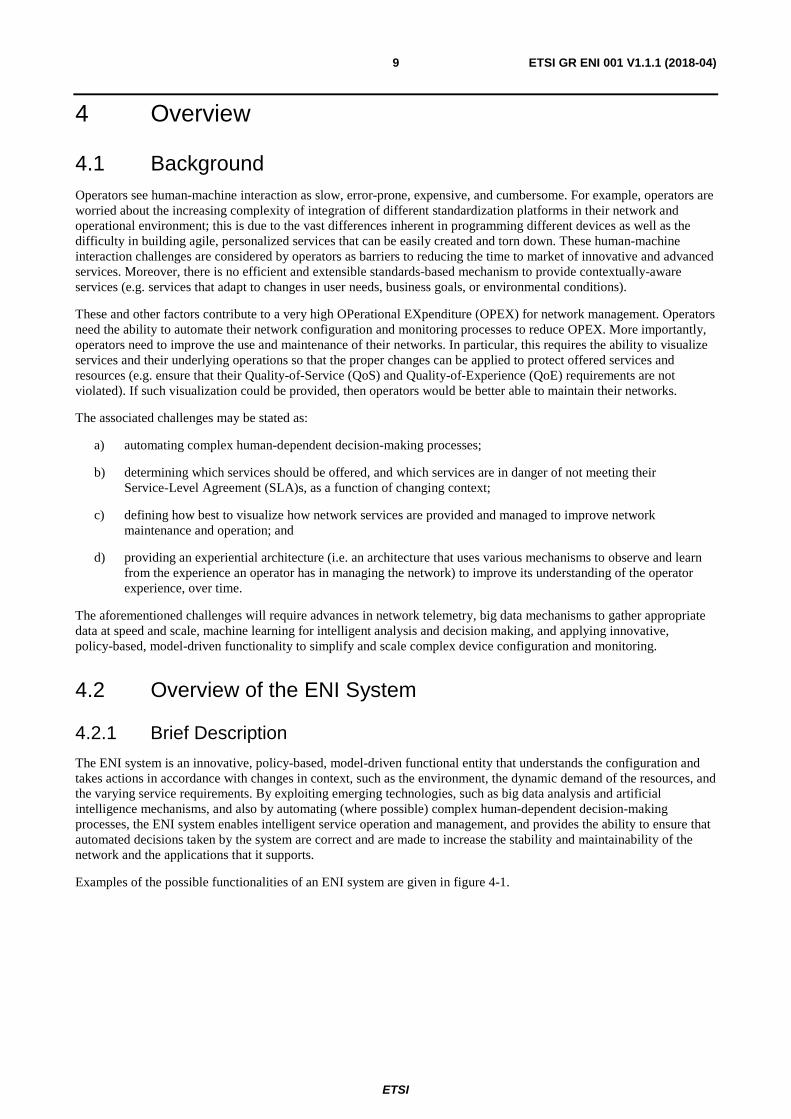
Examples of the possible functionalities of an ENI system are given in figure 4-1.
ETSI
ETSI GR ENI 001 V1.1.1 (2018-04)10
Figure 4-1: Example of functionalities of ENI system
4.2.2 Expected Benefits
ENI system delivers enhanced customer experience by allowing operators to understand the operating status of their network and networked applications in near-real-time, and reconfigure their network. The ENI system automatically collects network status and associated metrics, faults, and errors, and then uses artificial intelligence to ensure network performance and quality of service are met at the highest possible efficiency (e.g. with the minimum required resources). An ENI system can also be used to find bottlenecks of service and/or failure of network. Both of these benefits are done on-demand, in response to changing contextual information.
The ENI system helps to increase the value of services provided by an operator to its customers by rapidly on-boarding new services, enabling the creation of a new ecosystem of cloud consumer and enterprise services, reducing Capital and Operational Expenditures, and providing efficient operations.
5 General use cases
5.1 Introduction This clause describes the use cases and scenarios identified by the ENI ISG. Each use case includes a description of how an ENI system can be applied, and the benefits it provides.
A list of the use cases included in the present document are categorized into the following four categories (table 5-1):
1) Infrastructure Management: This category of use cases covers the processes related to the management of the network infrastructure (e.g. adjustment of allocated and provided services, maintenance, capability specification, and planning). In particular, it is about using policies for managing the network infrastructure, enabled by placing analytics in the control loop and using the results of the analytics as part of the input to policy-based management of the infrastructure.
2) Network Operations: Use cases described in this category are concerned with running the network, where the runtime contexts of the network are extracted and analysed, and the management operations are performed and optimized dynamically at runtime.
3) Service Orchestration and Management: This category of use cases relates to the service and order management, covering processes such as activation using the operator's business channels or customer portals. It is about providing differentiated SLAs for different applications, including vertical applications, through the application of machine learning in an intelligent entity, i.e. ENI. For example, services can be differentiated based on level (e.g. gold vs. silver vs. bronze classes of service) as well as based on the type of application within a level (e.g. a video streaming service has a different service than FTP, even though both are applications that a particular customer has).
ETSI
ETSI GR ENI 001 V1.1.1 (2018-04)11
4) Assurance: Use cases described in this category are concerned with the functionality of network monitoring, trending, and prediction, as well as taking policy-based actions using knowledge learned from the network to facilitate network maintenance. This includes service runtime operations dedicated to guarantee continuous service delivery.
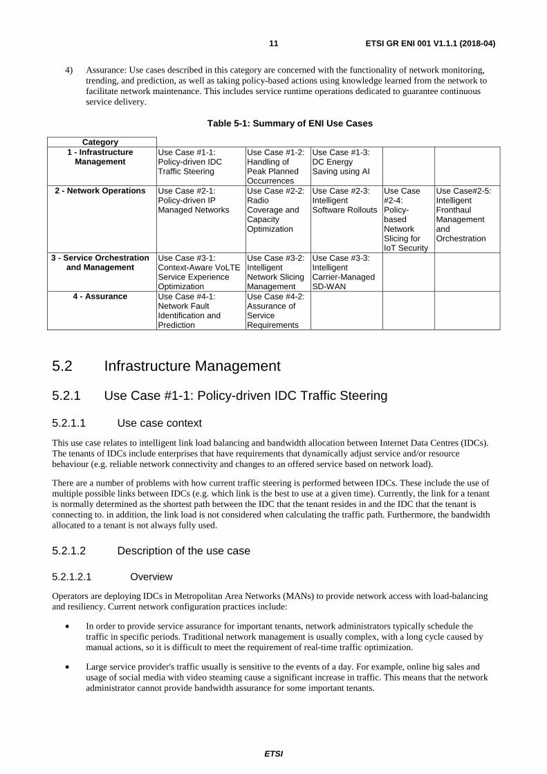
Table 5-1: Summary of ENI Use Cases
5.2 Infrastructure Management
5.2.1 Use Case #1-1: Policy-driven IDC Traffic Steering
5.2.1.1 Use case context
This use case relates to intelligent link load balancing and bandwidth allocation between Internet Data Centres (IDCs). The tenants of IDCs include enterprises that have requirements that dynamically adjust service and/or resource behaviour (e.g. reliable network connectivity and changes to an offered service based on network load).
There are a number of problems with how current traffic steering is performed between IDCs. These include the use of multiple possible links between IDCs (e.g. which link is the best to use at a given time). Currently, the link for a tenant is normally determined as the shortest path between the IDC that the tenant resides in and the IDC that the tenant is connecting to. in addition, the link load is not considered when calculating the traffic path. Furthermore, the bandwidth allocated to a tenant is not always fully used.
5.2.1.2 Description of the use case
5.2.1.2.1 Overview
Operators are deploying IDCs in Metropolitan Area Networks (MANs) to provide network access with load-balancing and resiliency. Current network configuration practices include:
• In order to provide service assurance for important tenants, network administrators typically schedule the traffic in specific periods. Traditional network management is usually complex, with a long cycle caused by manual actions, so it is difficult to meet the requirement of real-time traffic optimization.
• Large service provider's traffic usually is sensitive to the events of a day. For example, online big sales and usage of social media with video steaming cause a significant increase in traffic. This means that the network administrator cannot provide bandwidth assurance for some important tenants.
Category 1 - Infrastructure
Management Use Case #1-1: Policy-driven IDC Traffic Steering
Use Case #1-2: Handling of Peak Planned Occurrences
Use Case #1-3: DC Energy Saving using AI
2 - Network Operations Use Case #2-1: Policy-driven IP Managed Networks
Use Case #2-2: Radio Coverage and Capacity Optimization
Use Case #2-3: Intelligent Software Rollouts
Use Case #2-4: Policy-based Network Slicing for IoT Security
Use Case#2-5: Intelligent Fronthaul Management and Orchestration
3 - Service Orchestration and Management
Use Case #3-1: Context-Aware VoLTE Service Experience Optimization
Use Case #3-2: Intelligent Network Slicing Management
Use Case #3-3: Intelligent Carrier-Managed SD-WAN
4 - Assurance Use Case #4-1: Network Fault Identification and Prediction
Use Case #4-2: Assurance of Service Requirements
ETSI
ETSI GR ENI 001 V1.1.1 (2018-04)12
• The bandwidth requirements of tenants tend to change dynamically. Traditional static bandwidth allocation leads to low bandwidth utilization and redundancy.
• The imbalance across multiple links leads to inefficient resource utilization. For example, it is possible that the utilization of a link reaches a certain threshold, while other links' loads remain low.
5.2.1.2.2 Motivation
The ENI system can be used to achieve intelligent link load balancing and intelligent bandwidth allocation. In ENI, policies can be modified by using machine learning to fill in important parameters, such as available links, link bandwidth, real-time link utilization, and other predefined constraints. Three examples of the predefined constraints to be considered before modifying the policies are:
1) each link is predefined with a threshold of the maximum bandwidth and cannot be exceeded;
2) flow of a client at a specific service level (e.g. gold) cannot be switched;
3) the maximum times of switching specific service from one link to another link is predefined and cannot be exceeded.
Such policies can be used to better manage the network and achieve autonomous service traffic monitoring and network resource optimization. It can also be used to adjust the service along different links of an IDC, thus improving the operator's experience through enhanced network resilience and service QoS and QoE.
The ENI system also:
• predicts changes by using AI in the tenant's service requirements based on historical data (e.g. the type of QoS to be provided for a given service based on the type of application and metadata);
• collects and analyses real-time data, given the service adjustment recommendations (e.g. which metadata and metrics to monitor based on the type of service and the type of changes applied);
• corrects the prediction result according to the adjustment recommendations, and converges to an ideal service management policy;
• analyses QoS and other applicable data and metadata to make the final service policy modifications; this is then stored as a reusable set of objects.
By using the above intelligent service adjustment policy provided by the ENI system, real-time, dynamic, and automated resource allocation and adjustment to the service can be achieved. The bandwidth utilization is improved. Meanwhile, it provides bandwidth assurance for important tenants according to the service level.
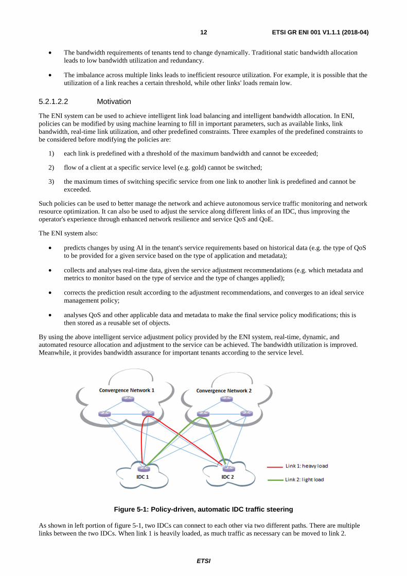
Figure 5-1: Policy-driven, automatic IDC traffic steering
As shown in left portion of figure 5-1, two IDCs can connect to each other via two different paths. There are multiple links between the two IDCs. When link 1 is heavily loaded, as much traffic as necessary can be moved to link 2.
ETSI
ETSI GR ENI 001 V1.1.1 (2018-04)13
5.2.1.2.3 Actors and Roles
• IDC network.
• ENI System.
• Network manager (City Level).
Stakeholders managing the above:
• Operators.
5.2.1.2.4 Initial context configuration
• The network administrator's inputs the policies;
• IDCs connect to each other via different links;
• network traffic routed via different links is defined according to policies;
• bandwidth of tenant may need to be adjusted in real time according to the dynamic needs of the tenant and the operational context.
5.2.1.2.5 Trigger conditions
• Utilization of a link or bandwidth of a tenant exceeds the configured threshold (e.g. as defined in an SLA).
• Change in operational requirements.
5.2.1.2.6 Operational Flow of the actions
For intelligent link load balancing:
1) network administrator pre-configures the threshold/constraint of link utilization and appropriate metadata and metrics to monitor link loads;
2) ENI system uses the network administrator's input to modify policies considering, for example, available links, bandwidth, link utilization, and constraints;
3) network administrator executes policies and ensures they all execute correctly (i.e. without error);
4) the ENI system adapts to monitor metrics, metadata, and other information (as defined by the above generated policies) to achieve measured improvements;
5) IDC network uses the policies to manage the network behaviour.
For intelligent bandwidth allocations:
• network administrator pre-configures the threshold of bandwidth utilization and appropriate metadata and metrics to monitor bandwidth;
• ENI system collects the bandwidth usage data for each tenant for a specified time period;
• ENI system preprocesses the data to extract the appropriate characteristics of the tenant's service to determine if the allocated bandwidth is sufficient or not;
• ENI system establishes an appropriate mathematical model to predict the bandwidth requirements of tenants at different times in the coming year;
• ENI system collects and analyses real-time bandwidth usage data for tenants;
• when the configured bandwidth utilization threshold is danger of being reached, the ENI system proactively adjusts the bandwidth allocation policies for the affected tenants, taking into account the QoS policy and other SLA policies of each tenant.
ETSI
ETSI GR ENI 001 V1.1.1 (2018-04)14
5.2.1.2.7 Post-conditions
The impact of dynamic polices:
• Network traffic is balanced.
• Appropriate metrics and metadata are continually gathered to ensure that the service requirements are met or exceeded.
• Bandwidth for the tenant is assured and automatically adjusted in real-time.
• Bandwidth utilization is improved.
5.2.2 Use Case #1-2: Handling of Peak Planned Occurrences
5.2.2.1 Use case context
Currently, most services share a common infrastructure where resource allocation is a very critical process. When a network operator extends its infrastructure to a new area or upgrades an already existent, it makes an assessment on the number of customers and services the infrastructure will serve under normal operation scenarios. Then, when provisioning services, the configuration of the infrastructure is performed once and usually does not change during the service lifecycle. Although advanced QoS strategies help to mitigate peak resources usage scenarios, it still constitutes a very static and slow process for today's services, which imply the need for the process to become more and more dynamic. Moreover, when considered as adequate and feasible, a network operator may make use of mobile stations for such temporary increases on network capacity.
Typical peak scenarios may be characterized by the occurrence of localized and temporary bursts of network traffic caused by planned events, e.g. soccer games, or unplanned, e.g. natural catastrophes, which may lead to critical service level degradation or even service disruption along with the subsequent impact in operators, in services as well as in end user's experience. In particular, for network operators, service degradation and/or disruption constitutes something that is to be avoided no matter at what cost as it jeopardizes network operator's image as a service provider among its customers.
In the present Use Case, only planned events will be taken into account.
5.2.2.2 Description of the use case
5.2.2.2.1 Overview
Service prioritization and management of resource sharing infrastructures are very complex processes for operators, which take a considerable amount of time for planning, and are normally performed only once in a given area. When dealing with temporary planned events, it is necessary to calculate the stress on the network infrastructure and define backup action plans to mitigate potential service degradation or even disruptions. Additionally, after the end of the event it is necessary to revert the temporary changes to the normal usage conditions.
An example of such a temporary planned event could be the case of a certain area, served by a network infrastructure for telecommunication services, which will be hosting a music event that will be broadcasted by live television. Currently, the network infrastructure is providing resources to several service instances in a shared manner. A relatively large crowd is expected at the event and if no actions are taken by the network operator there is the possibility of degradation on some of the services that make use of that region's infrastructure.
Analysis performed during the planning of events may also encompass the ability to extend the current infrastructure capacity of that area.
The current Use Case is further described by the following set of components and features.
ETSI
ETSI GR ENI 001 V1.1.1 (2018-04)15
5.2.2.2.2 Motivation
With the ENI system, the use of AI methods on helping to understand the context dynamicity and on predicting potential peak traffic scenarios becomes quite important. More specifically, the AI can perform the calculation of possible scenarios for planned events by making use of machine learning, e.g. by taking into account events history. On the other hand, it can also assist on the calculation based on the expected response of network equipment under stress, which can also help on the preparation and definition of the necessary backup action plans. In addition, the ENI system can also evaluate, for all these scenarios, if the use of resource sharing techniques is enough to support the increase of network traffic or if there is the need for additional measures, e.g. mobile stations that provide additional physical resources.
Still another benefit related to the AI capability to provide more realistic predictions lies in the possibility for network operators to use narrower margins of the total amount of resources when they wish to extend the current resource capacity of a given region. With these new tools, network operators may enforce pre-defined policies to govern the responses of the ENI System, e.g. do not use mobile stations if the peak consumption is not expected to exceed 90 % of the current network capacity.
5.2.2.2.3 Actors and Roles
The presence of the following actors/entities as well as their associated roles are envisaged in the current Use Case:
• Customers/clients: end users that enjoy the delivery of a service.
• Network Administrator: entity/person responsible for the initial policy design that encompasses the planning of the Network Infrastructure regarding the mitigation impact of planned events, which may involve the extension of the infrastructure capacity. With the assistance of the ENI System regarding these planning activities, this entity/person is in a position to chooses the most suitable backup action/plan to be enforced.
• Network Infrastructure: network elements and resources that participate in service fulfilment procedures.
• Network Operator: owner of the Network Infrastructure that is used to provide services to customers/clients.
• Operations support system/Business support system (OSS/BSS): operational and business systems that belong to the management system of network operators. In this case they are providing, among others, monitoring, actuation, internal records of very different items that may range from products to resources, as well as other business interfaces dedicated to external entities.
• ENI System: component that governs service fulfilment and participates in planning and configuration procedures upon occurrence of planned scenarios that may impact service delivery, which may encompass situations involving extension of infrastructure capacity.
5.2.2.2.4 Initial context configuration
The network is operating in perfect conditions with all its components working in good shape.
5.2.2.2.5 Triggering conditions
A music event is scheduled for a certain area and may lead to local service degradation or disruption. On occurrence of the planned event, backup actions, previously calculated by the ENI System and validated by the Network Administrator, are triggered. Those backup actions may encompass extensions on infrastructure capacity.
5.2.2.2.6 Operational flow of actions
The following sequence of actions may be identified:
1) After receiving a notification of a new event e.g. a music festival, the ENI System makes use of AI methods to calculate and produce a report containing several scenarios and their respective outcome depending on the size of the crowd and expected local resource consumption. For each scenario, it also produces a backup action plan, i.e. possible changes to local QoS profiles or additional resources needed, taking into account previously defined policies.
2) In its notification report, the ENI System signals one of the scenarios as the most suitable and asks the Network Administrator for validation.
ETSI
ETSI GR ENI 001 V1.1.1 (2018-04)16
3) The Network Administrator evaluates the proposed scenarios and backup plans, validates one of them, and notifies the ENI System about its choice.
4) Upon receiving the Network Administrator's reply, the ENI System elaborates a schedule containing a roadmap of the backup actions to be subsequently performed.
5) On occurrence of the planned event, the ENI System triggers the proper configuration operations via OSS components on impacted network infrastructure resources, including possible redundant resources that may be reserved for any deviation on the predicted consumption.
6) During the event, the ENI System increases the monitoring resolution on the previously mentioned resources.
7) If found as necessary, it may activate additional resources, if available, previously reserved for any deviation on the predicted consumption.
8) At the end of the event the ENI system triggers the rollback of the network resources configuration to the state where it was immediately before the event.
5.2.2.2.7 Post-conditions
The local network infrastructure is operating according to the planned deployment prior to the event. All information regarding network infrastructure during the event is stored to increase the prediction capabilities of the ENI System.
5.2.3 Use Case #1-3: Energy optimization using AI
5.2.3.1 Use case context
By introducing Network Function Virtualization (NFV) different virtual networks can be deployed on the same NFV Infrastructure (NFVI) for different network services. The Virtual Network Function (VNF) instances are implemented on Virtual Machines (VMs) or Containers. And the VNF instances can be instantiated, scaled in/out, or terminated on demand by using Management and Orchestration (MANO) system or any other form of orchestrator. The VNF instances can be easily moved from one server to another server by using VM/Container migration technologies. Therefore, the services provided by the VNFs can be steered from one server to another server along with the VM/Container migration.
With the trend of NFV, more and more DCs will be deployed to replace the traditional Central Offices in the operators' network. The data centres (DC) are made up of many servers with huge power consumption. Typically, the servers in a DC take 70 % of the total power consumption. The other equipment including switches, routers, storage equipment and air conditioners take the other 30 % of the total power consumption. The servers are deployed and running to meet the requirement of peak hour service, which means the servers are normally at high power-up state at full time even in non-peak hours. It is however possible to move the services to some of the servers and turn the other servers to idle state in non-peak hours, with the aim of optimizing the power usage at the DC. It should be noted that such mechanism of energy optimization can be applied widely to other network resources in addition to data centres. In the following, reducing waste energy in individual DCs is used as an example for this use case to elaborate how NFV and AI can be combined to optimize usage of the energy networks.
5.2.3.2 Description of the use case
5.2.3.2.1 Overview
Traditional ways of DC energy saving are normally done manually and the effect is not obvious. Power consumption of the DCs, same as the other network physical resources, represents a large portion of the cost for operators, and causes environmental concerns. Consisting primarily of a homologous architecture/resource pool, the scope of what can be optimized in an intra-DC context is limited. It is however, a necessary first step towards greater AI-driven improvements that are realizable with the additional consideration of both inter-DC orchestration and/or the exploitation of heterogeneous network resource pools (such as edge or IoT devices). The consideration of these additional factors will enable the minimization of the carbon foot print through intelligent resource management. For example, by relying solely on edge device compute resources in periods of low demand, an ENI system could identify and act on these requirements in an autonomous fashion ensuring that OPEX is optimized, among other key performance indicators (KPIs).
ETSI
ETSI GR ENI 001 V1.1.1 (2018-04)17
5.2.3.2.2 Motivation
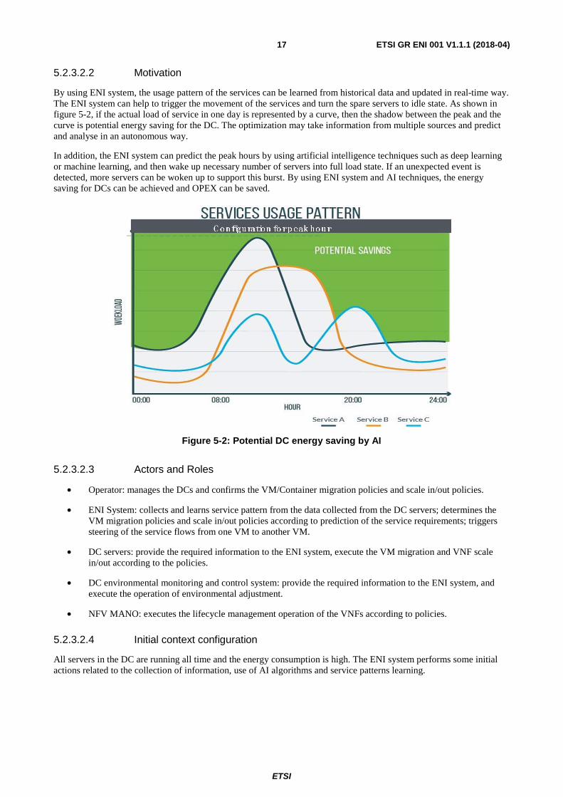
By using ENI system, the usage pattern of the services can be learned from historical data and updated in real-time way. The ENI system can help to trigger the movement of the services and turn the spare servers to idle state. As shown in figure 5-2, if the actual load of service in one day is represented by a curve, then the shadow between the peak and the curve is potential energy saving for the DC. The optimization may take information from multiple sources and predict and analyse in an autonomous way.
In addition, the ENI system can predict the peak hours by using artificial intelligence techniques such as deep learning or machine learning, and then wake up necessary number of servers into full load state. If an unexpected event is detected, more servers can be woken up to support this burst. By using ENI system and AI techniques, the energy saving for DCs can be achieved and OPEX can be saved.
Figure 5-2: Potential DC energy saving by AI
5.2.3.2.3 Actors and Roles
• Operator: manages the DCs and confirms the VM/Container migration policies and scale in/out policies.
• ENI System: collects and learns service pattern from the data collected from the DC servers; determines the VM migration policies and scale in/out policies according to prediction of the service requirements; triggers steering of the service flows from one VM to another VM.
• DC servers: provide the required information to the ENI system, execute the VM migration and VNF scale in/out according to the policies.
• DC environmental monitoring and control system: provide the required information to the ENI system, and execute the operation of environmental adjustment.
• NFV MANO: executes the lifecycle management operation of the VNFs according to policies.
5.2.3.2.4 Initial context configuration
All servers in the DC are running all time and the energy consumption is high. The ENI system performs some initial actions related to the collection of information, use of AI algorithms and service patterns learning.
ETSI
ETSI GR ENI 001 V1.1.1 (2018-04)18
5.2.3.2.5 Triggering conditions
The following trigger types associated with the ENI system may be identified:
• The ENI system predicts that the required resources of a service will fall below a certain threshold in a certain period.
• The ENI system predicts that the required resources of a service will grow up higher than a certain threshold in a certain period.
• The ENI system decides to change the DC environmental settings.
• The ENI system detects a change of the service pattern learned before.
5.2.3.2.6 Operational flow of actions
The following initial sequence of actions may be identified:
1) The ENI system collects and stores information of the virtual networks, including CPU usage, storage usage, and network usage for each VNF, etc. as well as the power consumption information and environmental information.
2) The ENI system uses AI algorithm to build the relations between the network service and its required resources, and the relations between the power consumption and the environment settings including e.g. the location of the running servers, the setting of the cooling system, etc.
3) The ENI system learns the service pattern and predicts the required resources of the service in a certain period in the future, e.g. the next hour.
The following triggers and subsequent actions may be identified:
1) When the ENI system predicts that the required resources of a service will fall below a certain threshold in a certain period, and the service configured by the operator as able to be moved, the ENI system triggers, directly or indirectly, the NFV MANO system to migrate the services and VMs/Containers providing this service to another selected server:
a) If the VMs/Containers on one server are all migrated to another server, the spare server is turned into idle mode.
2) When the ENI system predicts that the required resources of a service will grow up higher than a certain threshold in a certain period, the ENI system triggers the scale out of the existing VNF and bring up new VMs/Containers:
a) If the running servers cannot provide the required resources of a new VM/Container according to prediction, the ENI system wakes up a selected idle mode server.
3) The ENI system may decide to change the DC environmental monitoring and control system to adjust the environmental settings when a server is woke up or turned into the idle mode.
4) When the ENI system detects a change of the service pattern learned before, the ENI system will adjust the VM/Container migration policies and scale in/out policies.
5.2.3.2.7 Post-conditions
Servers in the DC are dynamically turned to idle and waken up according to the service pattern; therefore the cost of power consumption is reduced as much as possible.
ETSI
ETSI GR ENI 001 V1.1.1 (2018-04)19
5.3 Network Operations
5.3.1 Use Case #2-1: Policy-driven IP managed networks
5.3.1.1 Use case context
There are some types of network nodes that need to allocate IP addresses to end users. Examples include Broadband Remote Access Server (BRAS), Dynamic Host Configuration Protocol (DHCP) server, and Carrier Grade Network Address Translation (CGN). Each of these network nodes needs to be configured with IP addresses (i.e. from an IP address pool), which they can use to allocate to the end users. Currently, the plan and configuration of IP address pools rely on manual configuration that is fundamentally static in nature.
5.3.1.2 Description of the use case
5.3.1.2.1 Overview
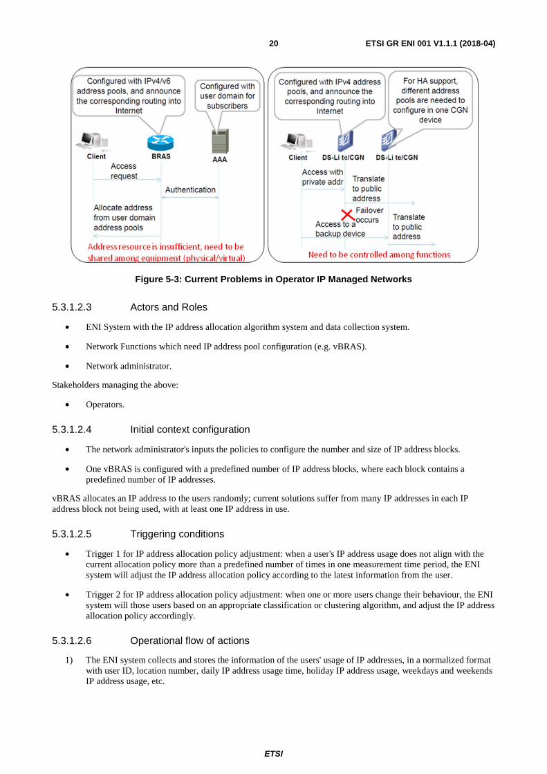
In a common scenario of Home Access, the client sends an access request to a BRAS. The BRAS picks one IP address from its pre-configured IP address pool and allocates that IP address to this client; this enables this client to access the network using this IP address. CGN translates private address into public address. CGNs are configured with several public IP address pools. When there is a need for a CGN to translate the private IP address of one session from the client side to a public IP address for network side, the CGN picks one public IP address in its pre-configured public IP address pools, replaces the private IP address by the selected public IP address, and records this mapping.
5.3.1.2.2 Motivation
The traditional IP management approach suffers from low utilization of IP addresses and poor sharing among equipment. Manual address allocation is cumbersome, and scripts are fragile and cannot adjust to dynamic network conditions. There are several disadvantages:
• Currently certain operators do not have sufficient IP address resources, especially for IPv4.
• IP address resource utilization ratio is low in general: some network nodes have low utilization ratio of internal addresses; some devices suffer from tidal effect (i.e. high in peak period and low in idle period).
• Address resources are not shared among equipment, which leads to inefficiencies in deployment.
In this use case, the ENI System learns the pattern of user sessions, which consumes the IP addresses, and classifies the users accordingly. The ENI System generates IP address pool configuration policies and IP address allocation policies to improve the efficiency of the utilization of IP addresses.
Policy enables more intelligent usage of address pools and automates the address allocation. With policy-driven network resource optimization and network resource monitoring, it is possible to automatically adjust address allocation on different equipment using policies. Such policies may consider factors such as demand on address, utilization ratio, address usage lifecycle, and constraints (e.g. the rejection rate of a BRAS or CGN, or thresholds that apply to address utilization). This allows more intelligent usage of address pools and automates the address allocation process, where improved operator experience can be expected. It also ensures more consistent operation of address allocation, which also improves the operator experience.
Such a use case is illustrated in figure 5-3.
ETSI
ETSI GR ENI 001 V1.1.1 (2018-04)20
Figure 5-3: Current Problems in Operator IP Managed Networks
5.3.1.2.3 Actors and Roles
• ENI System with the IP address allocation algorithm system and data collection system.
• Network Functions which need IP address pool configuration (e.g. vBRAS).
• Network administrator.
Stakeholders managing the above:
• Operators.
5.3.1.2.4 Initial context configuration
• The network administrator's inputs the policies to configure the number and size of IP address blocks.
• One vBRAS is configured with a predefined number of IP address blocks, where each block contains a predefined number of IP addresses.
vBRAS allocates an IP address to the users randomly; current solutions suffer from many IP addresses in each IP address block not being used, with at least one IP address in use.
5.3.1.2.5 Triggering conditions
• Trigger 1 for IP address allocation policy adjustment: when a user's IP address usage does not align with the current allocation policy more than a predefined number of times in one measurement time period, the ENI system will adjust the IP address allocation policy according to the latest information from the user.
• Trigger 2 for IP address allocation policy adjustment: when one or more users change their behaviour, the ENI system will those users based on an appropriate classification or clustering algorithm, and adjust the IP address allocation policy accordingly.
5.3.1.2.6 Operational flow of actions
1) The ENI system collects and stores the information of the users' usage of IP addresses, in a normalized format with user ID, location number, daily IP address usage time, holiday IP address usage, weekdays and weekends IP address usage, etc.
ETSI
ETSI GR ENI 001 V1.1.1 (2018-04)21
2) The ENI system uses one or more classification or clustering algorithms to build an appropriate model. Users are labelled based on their behaviour characteristics by using an appropriate algorithm, according to their historical and contextual information (e.g. location information, time of attachment and detachment, types of applications used, and amount of data transferred).
3) The ENI system modifies policies to re-configure the number and size of IP address blocks to be allocated to each user group, as well as the IP address allocation mechanisms.
4) IP address blocks and IP address allocation policies are sent to the BRAS for processing:
a) When a user attaches to the BRAS, the BRAS allocates an IP address to the user in his/her corresponding IP address block, according to the IP address allocation policy and the user information including his/her equipment identifier.
b) When the current usage of one IP address block reaches a threshold, the BRAS will select another IP address block with the same characteristics for further IP address allocation to the same type of users.
c) If all IP addresses in an IP address block are not in use, and the IP addresses are not kept for redundancy purposes, this IP address block will be recycled.
5) When triggered, the ENI system will regroup the users and adjust the IP address allocation policy accordingly.
6) When a user attached to the BRAS requesting for an IP address, the BRAS will select a most frequently used IP address block among the ones mapping to the user label, and allocate an IP address in this block to the user.
5.3.1.2.7 Post-conditions
All current users have the minimum number of IP addresses allocated or reserved. IP address pools are optimized.
5.3.2 Use Case #2-2: Radio Coverage and capacity optimization
5.3.2.1 Use case context
Coverage and capacity optimization (CCO) is one of the typical operational tasks of the radio access network (RAN). CCO aims to provide the required capacity in the targeted coverage areas, to minimize the interference and maintain an acceptable quality of service in an autonomous way. To achieve these targets, antenna power and configuration (pilot power, antenna down tilt, antenna azimuth, or massive MIMO pattern in 5G) play a critical role, as they affect the direction of the antenna radiation pattern, therefore can be used to improve the received signal strength in the own cell as well as to reduce the interference to neighbouring cells.
The CCO task also exists in enterprise wireless local area network (WLAN) scenario. In enterprise WLAN, an access point (AP) controller sets multiple APs' RF parameters (e.g. channel frequency, bandwidth, power) to provide full coverage and minimize the inter-cell interference (namely dynamic channel allocation and transmit power control).
5.3.2.2 Description of the use case
5.3.2.2.1 Overview
CCO allows the system to periodically adapt to the changes in traffic (i.e. load and location) and the radio environment by adjusting the key radio frequency (RF) parameters (e.g. antenna configuration and power). For the online CCO task, it is not possible to find definite function to map between the RF parameters and the target coverage and capacity performance. The main reason is that the set of configurable RF parameters is multi-dimensional, and each RF parameter has wide range of values, leading to very large number of possible options.
ETSI
ETSI GR ENI 001 V1.1.1 (2018-04)22
5.3.2.2.2 Motivation
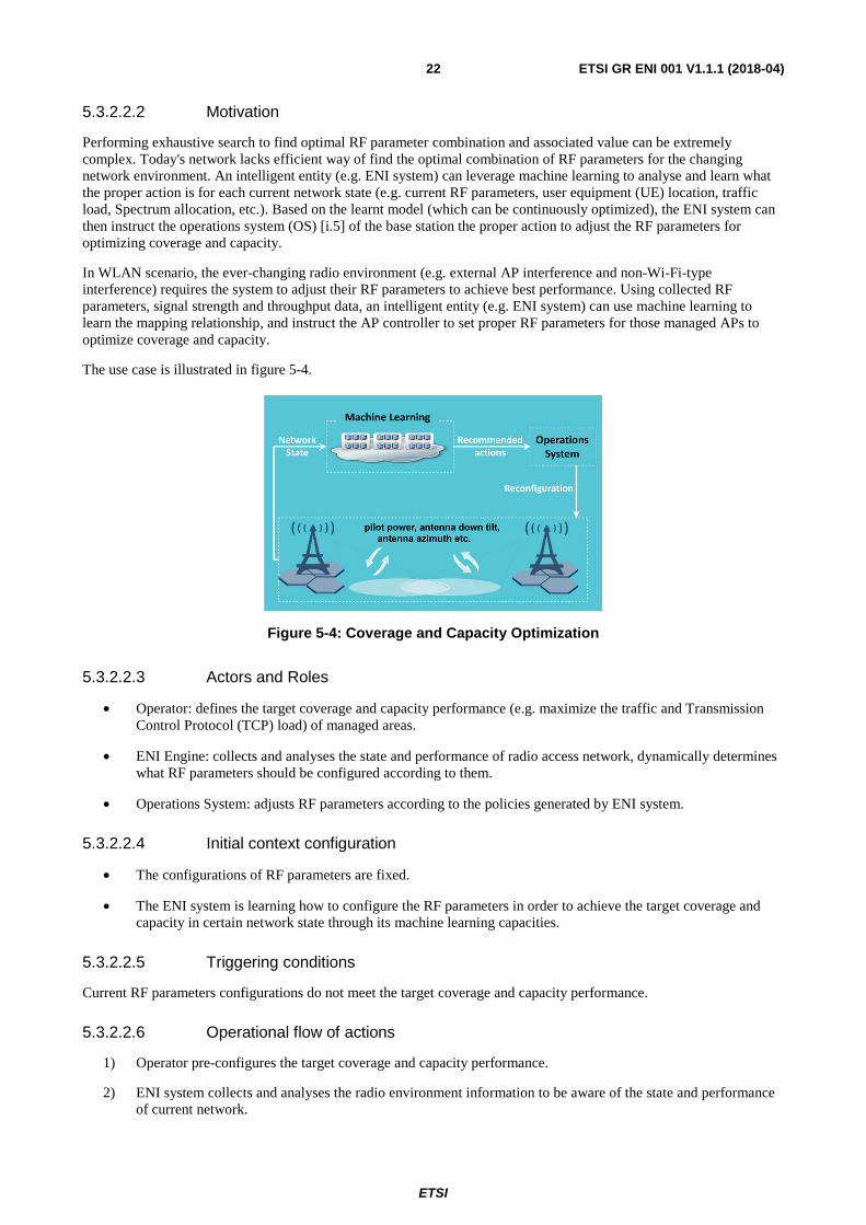
Performing exhaustive search to find optimal RF parameter combination and associated value can be extremely complex. Today's network lacks efficient way of find the optimal combination of RF parameters for the changing network environment. An intelligent entity (e.g. ENI system) can leverage machine learning to analyse and learn what the proper action is for each current network state (e.g. current RF parameters, user equipment (UE) location, traffic load, Spectrum allocation, etc.). Based on the learnt model (which can be continuously optimized), the ENI system can then instruct the operations system (OS) [i.5] of the base station the proper action to adjust the RF parameters for optimizing coverage and capacity.
In WLAN scenario, the ever-changing radio environment (e.g. external AP interference and non-Wi-Fi-type interference) requires the system to adjust their RF parameters to achieve best performance. Using collected RF parameters, signal strength and throughput data, an intelligent entity (e.g. ENI system) can use machine learning to learn the mapping relationship, and instruct the AP controller to set proper RF parameters for those managed APs to optimize coverage and capacity.
The use case is illustrated in figure 5-4.
Figure 5-4: Coverage and Capacity Optimization
5.3.2.2.3 Actors and Roles
• Operator: defines the target coverage and capacity performance (e.g. maximize the traffic and Transmission Control Protocol (TCP) load) of managed areas.
• ENI Engine: collects and analyses the state and performance of radio access network, dynamically determines what RF parameters should be configured according to them.
• Operations System: adjusts RF parameters according to the policies generated by ENI system.
5.3.2.2.4 Initial context configuration
• The configurations of RF parameters are fixed.
• The ENI system is learning how to configure the RF parameters in order to achieve the target coverage and capacity in certain network state through its machine learning capacities.
5.3.2.2.5 Triggering conditions
Current RF parameters configurations do not meet the target coverage and capacity performance.
5.3.2.2.6 Operational flow of actions
1) Operator pre-configures the target coverage and capacity performance.
2) ENI system collects and analyses the radio environment information to be aware of the state and performance of current network.
ETSI
ETSI GR ENI 001 V1.1.1 (2018-04)23
3) ENI system determines the RF parameters configuration according to the current network state and target coverage and capacity performance.
4) Operations system reconfigures the RF parameters according to the output of ENI system.
5.3.2.2.7 Post-conditions
• The RF parameters dynamically adjust according to the changing radio environment.
• The target coverage and capacity performance is met.
5.3.3 Use Case #2-3: Intelligent Software Rollouts
5.3.3.1 Use Case context
Physical resources such as routers, during their lifetime, need to have their firmware updated, not only for the support of new services or functionalities, but also to fix existent impairments. In some cases a firmware rollout can take several months to plan and enforce.
Indeed, updating a physical resource firmware constitutes a particularly delicate use case since it involves service disruption, potential bugs on the new version or in the worst case scenario the need to use workforce for equipment replacement. Thus, operators are very cautious when they need to perform a firmware rollout for a given resource, usually by dividing the complete process in different phases, either by geographical locations or different classes of clients.
With the arrival of new paradigms such as NFV or Mobile edge computing (MEC) into the marketplace, this problem can become even worst as more (virtual) software-based resources are being dealt with and there is less time between releases.
5.3.3.2 Description of the Use Case
5.3.3.2.1 Overview
As just stated above, this rollout Use Case may become even worst when dealing with (virtual) software-based resources, in particular if dynamic on boarding of VNFs or of other type of applications is supported, in which case automatized and intelligent software rollout becomes vital for operators. With dynamic on boarding, common in DevOps environments, automatic tests to benchmark and building of a profile for a given application is possible and recommended. The subject of performing tests to benchmark network functions is very relevant for network operators and is a common procedure with their physical counterparts [i.4].
The flow of actions for both physical and virtualised is similar and should take into account the best practises from Cloud Computing and DevOps. However, since the rollout of virtualised equipment is considered to be more challenging due to the fact that the number of updates for software-based components is performed much more times, this type of update will be the only one considered in the present Use Case.
The current Use Case is further described by the following set of components and features.
5.3.3.2.2 Motivation
By making use of the ENI System, operators can define different policies for different types of rollouts and for different types of resources. One example could be the definition of a hierarchy of parameters for phasing out the rollout, e.g. client class, geographical location, or time of the day. In addition, and also taking dynamic on boarding and DevOps environments into consideration, different types of policies can be defined by using the ENI System, such as:
• Development, e.g. tests should provide a correlation between network function performance (throughput, jitter, delay) and resource utilization (CPU, RAM, I/O).
• Update schedule, e.g. for enterprise customers schedule updates outside business hours.
• Update procedures, e.g. create backup of current versions of software instances when updating instances from platinum level services in order to prevent service disruption in case of occurrence of significant errors.
ETSI
ETSI GR ENI 001 V1.1.1 (2018-04)24
• Failure procedures, e.g. considering two types of errors where the response would be defined by policies:
i) critical errors, which make the ENI System stop the update movement process, and initiate the rollback to an already updated instance; and
ii) minor errors, which makes the ENI System retry the update.
NOTE: In this Use Case, only type ii) errors will be considered.
Thus, the use of AI methods becomes more important when moving software from testing to production by using automatized procedures.
5.3.3.2.3 Actors and Roles
The presence of the following actors/entities as well as their associated roles are envisaged in the current Use Case:
• Customers/clients: the operators themselves.
• Network Administrator: entity/person responsible for the initial policy design that encompasses the definition of different activities during rollouts.
• Network Infrastructure: infrastructure that includes resources that are meant to be upgraded or, in the worst case, replaced.
• ENI System: system solution that makes use of AI methods when upgrading or moving software from testing to production, and that enables the use of policies to govern updates to software instances. This solution also participates in software tests and builds a profile with information, e.g. correlation between network function performance (throughput, jitter, delay) and resource utilization (CPU, RAM, I/O), that can be used to improve fulfilment and assurance procedures.
• OSS/BSS: operational and business systems that belong to the management system of network operators. In this case they are providing, among others, monitoring, actuation, internal records of very different items that may range from products to resources, as well as other business interfaces dedicated to external entities.
5.3.3.2.4 Initial context configuration
The network is operating in perfect conditions with all its components in good shape. Moreover, the network operator already has a development environment that is specified to mimic the production environment. This development environment is used to run automatized tests in order to validate new software versions and build the respective software profile, where the series of tests are defined by network operator policies. Finally, the move of software from development to a production environment is also conditioned by network operator policies, thus governing the phased deployment of the new version.
5.3.3.2.5 Triggering conditions
A new software version of a virtual component is released by the vendor and is on boarded on a network operator infrastructure. The upload of a new software version to software repository triggers the start of automatic tests pre-defined by policies also previously enforced in the ENI System.
5.3.3.2.6 Operational flow of actions
The following sequence of actions may be identified:
1) A new software version is instantiated on the network operator development environment.
2) Within the new environment, the software is subject to a series of tests determined by pre-defined policies in the ENI System, which results, will be used to create a software profile.
3) During the tests, the ENI System starts analysing the behaviour of all the collected data and compares it with the profile of previous versions of software.
4) Since the results of the tests are conformant to previous versions, the ENI System is in position to allow the triggers for moving the new version from the development to the production environment.
ETSI
ETSI GR ENI 001 V1.1.1 (2018-04)25
5) The ENI System takes into account the pre-defined operator policies for the new software rollout and performs the scheduling of updates for the software instances.
6) The ENI System triggers the movement of the new version from the development to the production environment.
7) During the update, all platinum SLA customers of software instances are using a redundant software instance to avoid any service disruption.
8) Some instances monitoring data may detect an inconsistency with the application profile indicating a problem with the update. Since it is considered a minor error, the ENI System retries the update on failed instances.
9) At the end of the process, the ENI System may notify relevant software components, e.g. OSS/BSS, that the software rollout has been carried out successfully.
5.3.3.2.7 Post-conditions
The new software version has been updated on all deployed instances and inventories. The network and corresponding services are running steady.
5.3.4 Use Case #2-4: Policy-based network slicing for IoT security
5.3.4.1 Use Case context
In the near future, it is expected that smart cities will be built by using a myriad of IoT devices, where a significant number of them will be connected through 5G. These devices will play a vital role in the deployment of various services (e.g. civil protection or other services provided by the municipality, where each service will have its own target use and different device requirements).
To support this massive deployment of devices, the use of network slices will enable their aggregation either by functionality (e.g. security or city operations management support) or by other types of lower level requirements, such as low latency and high bandwidth.
In this context, the handling of Distributed Denial of Service (DDOS) attacks plays a crucial role as those devices are usually meant to be part of the support to applications/services related to social interest.
NOTE: As an example of the severity of damage that these type of devices can achieve in such environments, consider the October 2016 IoT incident, where several different devices where infected with a Botnet malware designed to perform a DDOS attack. The initial reports point to an attack that roughly doubles previous massive attacks, all thanks to the nature of IoT, where a huge number of devices deployed in a distributed way can be used to target specific network infrastructures.
Description of the Use Case One of the key benefits of the network slicing concept, from the IoT perspective, is that it adds value by offering network and cloud resources that can be used in an isolated, disjunctive or shared manner. In this context, network slicing can be used to support very diverse requirements imposed by IoT services as well as flexibility and scalability to support massive connections of different natures.
Different slices may be used and re-tasked to accommodate changes in context. This requires coordination and management of each slice. It is recommended that one or more AI algorithms are used to pre- and/or post-process the information gathered prior to executing a set of policy rules to manage a set of slices. In addition, the use of different AI algorithms to monitor the execution of the policy rules is recommended to ensure that the new behaviour of the set of slices is correct. The use of AI at these different places in the control loop is necessary to support the integration of millions of devices in complex topologies and distinct communication patterns, while still guaranteeing infrastructure security and optimal resource usage.
The use of AI in concrete scenarios addressing specific situations that involve DDOS attacks enables the ENI System to provide automatic and dynamic responses in different contexts. For example, when a set of IoT devices become infected, they may cause a service degradation or disruption; hence, they need to be isolated in order to be repaired or replaced. This also prevents the spreading of malware.
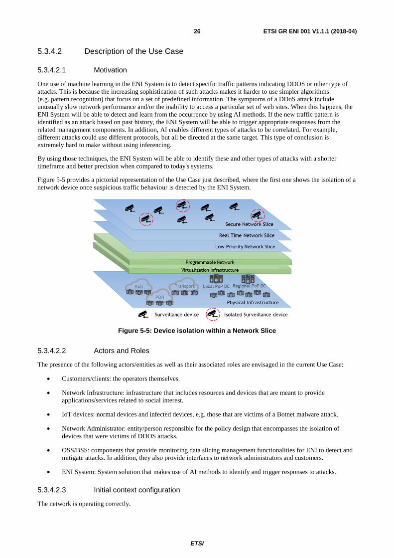
ETSI
ETSI GR ENI 001 V1.1.1 (2018-04)26
5.3.4.2 Description of the Use Case
5.3.4.2.1 Motivation
One use of machine learning in the ENI System is to detect specific traffic patterns indicating DDOS or other type of attacks. This is because the increasing sophistication of such attacks makes it harder to use simpler algorithms (e.g. pattern recognition) that focus on a set of predefined information. The symptoms of a DDoS attack include unusually slow network performance and/or the inability to access a particular set of web sites. When this happens, the ENI System will be able to detect and learn from the occurrence by using AI methods. If the new traffic pattern is identified as an attack based on past history, the ENI System will be able to trigger appropriate responses from the related management components. In addition, AI enables different types of attacks to be correlated. For example, different attacks could use different protocols, but all be directed at the same target. This type of conclusion is extremely hard to make without using inferencing.
By using those techniques, the ENI System will be able to identify these and other types of attacks with a shorter timeframe and better precision when compared to today's systems.
Figure 5-5 provides a pictorial representation of the Use Case just described, where the first one shows the isolation of a network device once suspicious traffic behaviour is detected by the ENI System.
Figure 5-5: Device isolation within a Network Slice
5.3.4.2.2 Actors and Roles
The presence of the following actors/entities as well as their associated roles are envisaged in the current Use Case:
• Customers/clients: the operators themselves.
• Network Infrastructure: infrastructure that includes resources and devices that are meant to provide applications/services related to social interest.
• IoT devices: normal devices and infected devices, e.g. those that are victims of a Botnet malware attack.
• Network Administrator: entity/person responsible for the policy design that encompasses the isolation of devices that were victims of DDOS attacks.
• OSS/BSS: components that provide monitoring data slicing management functionalities for ENI to detect and mitigate attacks. In addition, they also provide interfaces to network administrators and customers.
• ENI System: System solution that makes use of AI methods to identify and trigger responses to attacks.
5.3.4.2.3 Initial context configuration
The network is operating correctly.
ETSI
ETSI GR ENI 001 V1.1.1 (2018-04)27
5.3.4.2.4 Triggering conditions
A first trigger is when the ENI System detects changes in services provided (e.g. a web site).
A second trigger is when the ENI System identifies abnormal traffic patterns from a set of devices.
5.3.4.2.5 Operational flow of actions
The following sequence of actions may be identified:
1) The ENI system monitors services (e.g. a web site) and devices that support the service itself (e.g. the network and a supporting server farm) as well as provide access to the service, looking for anomalous behaviour.
2) The ENI system detects that an abnormal event has occurred (e.g. web site is no longer accessible, or the traffic patterns of a device do not correspond to its expected behaviour).
3) The ENI system analyses the changes indicated by the abnormal event, and determines whether this is an attack or not. If it is an attack, then it notifies the Network Administrator, requesting the necessary operations to mitigate the attack.
4) These OSS/BSS entities enforce related policies and isolate the infected IoT devices from the rest of the network.
5) These OSS/BSS entities also notify the Network Administrator and related customers, if applicable, about the occurrence of the attack and restores normal service to the customer.
5.3.4.2.6 Post-conditions
The infected devices have been identified and isolated from the network in a swift and efficient manner, and all other devices were able to maintain their normal operations.
If the customer's service was interrupted by the attack, then the customer's service is restored.
5.3.5 Use Case #2-5: Intelligent Fronthaul Management and Orchestration
5.3.5.1 Use Case context
Centralized radio access network (C-RAN) has been extensively considered for emerging and future cellular networks. In C-RAN, centralized RAN functions are located in an entity termed as Centralized Baseband Unit (BBU), and the remainder of radio access connectivity between the UE and the network are handled by Remote Radio Units (RRUs). Such an architecture enables functional split between BBU and RRUs. For example, RF and some physical layer (PHY) level functionalities can be handled at RRUs, while the rest can be moved to centralized BBUs.
Such functional split versus classical distributed RAN (D-RAN) brings several advantages including accelerated network deployment on RRU side, reduced operating costs (although Capital Expenditure can be high in short term), support for richer multi-node network cooperation and coordination (e.g. on Coordinated Multi-Point systems or Carrier Aggregation) and improved network performance, in particular at the cell edge.
To support such functional split, a Common Public Radio Interface (CPRI) has been proposed to support Fronthaul connectivity, which is the connection between BBU and RRUs. However, CPRI is believed to require strict high bandwidth, low delay, tight synchronization and additional transmission equipment partly attributed to its Point-to-Point connectivity paradigm.
To address the above issues, next generation Fronthaul interface (NGFI) including envisioned new variants of CPRI (eCPRI) target redefining interface flexibility and network functional split between remote and centralized units. Such an interface enables statistical multiplexing on Fronthaul bandwidth, decoupling interface traffic from some RF-level attributes (e.g. number of antennas) and results in more flexible remote unit connectivity to a centralized unit.
In line with recent advancement on NGFI, RRUs are divided into clusters; each cluster may possess one logical entity termed as Remote Aggregation Unit (RAU) that can be physically located as part of one of RRUs per cluster or as a separate individual entity. The RAU is in charge of radio resource management per cluster.
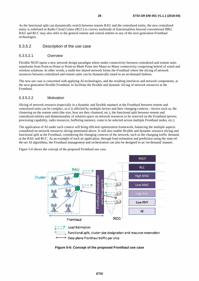
ETSI
ETSI GR ENI 001 V1.1.1 (2018-04)28
As the functional split can dynamically switch between remote RAU and the centralized entity, the new centralized entity is redefined as Radio Cloud Centre (RCC) to convey multitude of functionalities beyond conventional BBU. RAU and RCC may also refer to the general remote and central entities in any of the next generation Fronthaul technologies.
5.3.5.2 Description of the use case
5.3.5.2.1 Overview
Flexible NGFI opens a new network design paradigm where nodes connectivity between centralized and remote units transforms from Point-to-Point or Point-to-Multi Point into Many-to-Many connectivity comprising hybrid of wired and wireless solutions. In other words, a multi-tier shared network forms the Fronthaul where the slicing of network resources between centralized and remote units can be dynamically tuned in an on-demand fashion.
The new use case is concerned with applying AI technologies, and the resulting interfaces and network components, at the next generation flexible Fronthaul, to facilitate the flexible and dynamic slicing of network resources at the Fronthaul.
5.3.5.2.2 Motivation
Slicing of network resource (especially in a dynamic and flexible manner) at the Fronthaul between remote and centralized units can be complex, as it is affected by multiple factors and their changing contexts - factors such as, the clustering on the remote units (the size, how are they clustered, etc.), the functional split between remote and centralized entities and dimensionality of solution space on network resources to be reserved on the Fronthaul (power, processing capability, radio resources, buffering memory, route to be selected across multiple Fronthaul nodes, etc.).
The application of AI under such context will bring efficient optimization framework, balancing the multiple aspects considered on network resources slicing mentioned above. It will also enable flexible and dynamic resource slicing and functional split at the Fronthaul, considering the changing contexts of the network, such as the changing traffic demand, at the RAU and RCC. As an example of such an application, through load estimation and prediction using the state-of-the-art AI algorithms, the Fronthaul management and orchestration can also be designed in an 'on-demand' manner.
Figure 5-6 shows the concept of the proposed Fronthaul use case.
Figure 5-6: Concept of the proposed Fronthaul use case
ETSI
ETSI GR ENI 001 V1.1.1 (2018-04)29
5.3.5.2.3 Actors and Roles
• Operator: Provides interfaces to convey signalling on load estimation, service level agreements, slice-level requirements and traffic profiles (if any) to the ENI System.
• ENI System: Collects load estimation data (traffic demand, current configuration) from different RAU/RCC units; determines optimal Fronthaul parameters (e.g. functional split, clustering size per RAU); and reserves Fronthaul network resources accordingly between different RAU and RCC units.
• RAU/RCC units: Provide relevant input data (e.g. on load estimation) via Operator's interfaces to the ENI System and readjust their Fronthaul parameters (e.g. functional split, clustering size per RAU) according to output data from ENI System.
5.3.5.2.4 Initial context configuration
Network is configured with a default set of parameters on, e.g. a target Fronthaul KPI, the functional split, the cluster size, and the corresponding reservation of Fronthaul resources. The default parameters can be set by the network Operator.
5.3.5.2.5 Triggering conditions
When the Fronthaul KPI is below the target.
5.3.5.2.6 Operational flow of actions
1) ENI system collects Fronthaul parameters, current configurations and past and current traffic from different RAU/RCC Units.
2) ENI system makes decision on the Fronthaul parameters and feedbacks the parameters to the RAU/RCC units. Such decision can be made based on experiential learning of the ENI system given the current context.
3) RAU/RCC units receive and readjust their respective Fronthaul parameters.
4) ENI system reserves Fronthaul network resources. Fronthaul operation KPI is fed back to ENI system.
5) When triggered, the ENI system will reconfigure the parameters and reallocate the resources.
5.3.5.2.7 Post-conditions
Target Fronthaul KPI is guaranteed.
5.4 Service Orchestration and Management
5.4.1 Use Case #3-1: Context-aware VoLTE Service Experience Optimization
5.4.1.1 Use case context
As the mobile network evolves to 4G and 5G, an all-IP network will provide high definition voice transmission. VoLTE, namely Voice over LTE, it is an IP data transmission technology, which does not need a 2G or 3G network. In VoLTE, all business bears on 4G network, and can realize the unification of data and voice services using the same network. As a result, the 4G and 5G networks not only provide high-speed data services, but also provide high-quality audio and video services, the latter achieved via the use of the VoLTE technology.
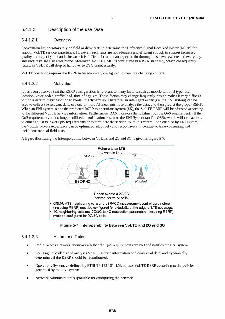
ETSI
ETSI GR ENI 001 V1.1.1 (2018-04)30
5.4.1.2 Description of the use case
5.4.1.2.1 Overview
Conventionally, operators rely on field or drive tests to determine the Reference Signal Received Power (RSRP) for smooth VoLTE service experience. However, such tests are not adequate and efficient enough to support increased quality and capacity demands, because it is difficult for a human expert to do thorough tests everywhere and every day, and such tests are also error prone. Moreover, VoLTE RSRP is configured in a RAN statically, which consequently results in VoLTE call drop or handover to 2/3G unnecessarily.
VoLTE operation requires the RSRP to be adaptively configured to meet the changing context.
5.4.1.2.2 Motivation
It has been observed that the RSRP configuration is relevant to many factors, such as mobile terminal type, user location, voice codec, traffic load, time of day, etc. These factors may change frequently, which makes it very difficult to find a deterministic function to model this dynamism. Therefore, an intelligent entity (i.e. the ENI system) can be used to collect the relevant data, use one or more AI mechanisms to analyse the data, and then predict the proper RSRP. When an ENI system sends the predicted RSRP to operations system [i.5], the VoLTE RSRP will be adjusted according to the different VoLTE service information. Furthermore, RAN monitors the fulfilment of the QoS requirements. If the QoS requirements are no longer fulfilled, a notification is sent to the ENI System (and/or OSS), which will take actions to either adjust to lower QoS requirements or to terminate the service. With this control loop enabled by ENI system, the VoLTE service experience can be optimized adaptively and responsively in contrast to time-consuming and inefficient manual field tests.
A figure illustrating the Interoperability between VoLTE and 2G and 3G is given in figure 5-7.
Figure 5-7: Interoperability between VoLTE and 2G and 3G
5.4.1.2.3 Actors and Roles
• Radio Access Network: monitors whether the QoS requirements are met and notifies the ENI system.
• ENI Engine: collects and analyses VoLTE service information and contextual data, and dynamically determines if the RSRP should be reconfigured.
• Operations System: as defined by ETSI TS 132 101 [i.5], adjusts VoLTE RSRP according to the policies generated by the ENI system.
• Network Administrator: responsible for configuring the network.
ETSI
ETSI GR ENI 001 V1.1.1 (2018-04)31
5.4.1.2.4 Initial context configuration
• The VoLTE RSRP was configured in RAN statically.
• The ENI system has learned how to configure the RSRP in order to ensure the VoLTE service experience.
5.4.1.2.5 Triggering conditions
The current VoLTE RSRP does not meet the VoLTE continuity coverage requirement.
5.4.1.2.6 Operational flow of actions
1) ENI system collects and analyses VoLTE service information (and any other necessary information, such as contextual data).
2) ENI system determines what the RSRP should be according to the current VoLTE service information.
3) Operations system reconfigures the RSRP according to the output of the ENI system.
4) RAN monitors whether the QoS requirements are met; if not, it notifies the ENI system.
5) ENI system recommends appropriate changes (e.g. rollback the RSRP, or make other configuration changes) to meet the QoS requirements.
6) Operations system implements recommended changes.
5.4.1.2.7 Post-conditions
• The VoLTE RSRP dynamically adjusts according to the changing network environment.
• The VoLTE service experience was optimized adaptively.
5.4.2 Use Case #3-2: Intelligent network slicing management
5.4.2.1 Use case context
The concept of network slicing has been introduced by the NGMN 5G whitepaper [i.2], which enables multiple logical self-contained networks to use a common physical infrastructure platform, enabling a flexible stakeholder ecosystem that allows technical and business innovation integrating network and cloud resources into a programmable, software-oriented network environment. From the perspective of 3GPP [i.1], network slicing enables operators to create networks customized to provide optimized solutions for different market scenarios which demands diverse requirements, e.g. in the areas of functionality, performance and isolation.
Network slicing can be used to support very diverse requirements imposed by IoT services and as well as flexible and scalable to support massive connections of different nature.
5.4.2.2 Description of the use case
5.4.2.2.1 Overview
The realization of the network slice concept is accomplished using network slice instances (NSIs), see figure 5-8. An NSI is an instance of a logical representation of Network Function(s) and corresponding resource requirements necessary to provide the required end to end (E2E) telecommunication services and network capabilities. An NSI typically covers multiple technical domains, which includes terminal, access network, transport network and core network, as well as DC domain that can host third-party applications from vertical industries.
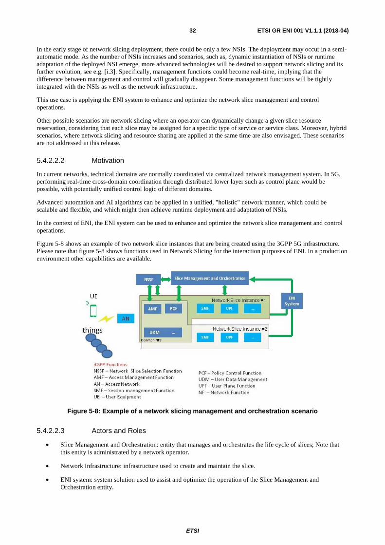
ETSI
ETSI GR ENI 001 V1.1.1 (2018-04)32
In the early stage of network slicing deployment, there could be only a few NSIs. The deployment may occur in a semi-automatic mode. As the number of NSIs increases and scenarios, such as, dynamic instantiation of NSIs or runtime adaptation of the deployed NSI emerge, more advanced technologies will be desired to support network slicing and its further evolution, see e.g. [i.3]. Specifically, management functions could become real-time, implying that the difference between management and control will gradually disappear. Some management functions will be tightly integrated with the NSIs as well as the network infrastructure.
This use case is applying the ENI system to enhance and optimize the network slice management and control operations.
Other possible scenarios are network slicing where an operator can dynamically change a given slice resource reservation, considering that each slice may be assigned for a specific type of service or service class. Moreover, hybrid scenarios, where network slicing and resource sharing are applied at the same time are also envisaged. These scenarios are not addressed in this release.
5.4.2.2.2 Motivation
In current networks, technical domains are normally coordinated via centralized network management system. In 5G, performing real-time cross-domain coordination through distributed lower layer such as control plane would be possible, with potentially unified control logic of different domains.
Advanced automation and AI algorithms can be applied in a unified, "holistic" network manner, which could be scalable and flexible, and which might then achieve runtime deployment and adaptation of NSIs.
In the context of ENI, the ENI system can be used to enhance and optimize the network slice management and control operations.
Figure 5-8 shows an example of two network slice instances that are being created using the 3GPP 5G infrastructure. Please note that figure 5-8 shows functions used in Network Slicing for the interaction purposes of ENI. In a production environment other capabilities are available.
Figure 5-8: Example of a network slicing management and orchestration scenario
5.4.2.2.3 Actors and Roles
• Slice Management and Orchestration: entity that manages and orchestrates the life cycle of slices; Note that this entity is administrated by a network operator.
• Network Infrastructure: infrastructure used to create and maintain the slice.
• ENI system: system solution used to assist and optimize the operation of the Slice Management and Orchestration entity.
ETSI
ETSI GR ENI 001 V1.1.1 (2018-04)33
• IoT devices: devices that can be represented as Things and can take part in the operation of the end to end slice.
• UE: any device, e.g. Smart phone, that is using the 3GPP cellular technology and can take part in the operation of the end to end slice.
5.4.2.2.4 Initial context configuration
The slices are created and configured; The ENI system through AI and machine learning capabilities is learning the configuration of the applied slices and as well the traffic patterns used by each of these slices; moreover, the ENI system measures the utilization of the network and other relevant parameters that define the satisfactorily operation of each slice and that needs to conform to the Service and Network KPIs requested by the operators.
5.4.2.2.5 Triggering conditions
When the ENI system concludes that the measured parameters associated with the operation of each slice do not conform to the Service and Network KPIs requested by the operators, then the ENI system notifies the Slice Management and Orchestration entity about this event.
5.4.2.2.6 Operational flow of actions
ENI system applying analysis and machine learning technologies can be used to enhance and optimize the network slice management and control operations and to assist the Slice Management and Orchestration entity to resolve any abnormal operation of each slice; some of the ENI system activities are listed below:
1) ENI system analyses the collected data associated to e.g. network topology, network traffic load, service characteristic, user location and movement, VNF type and placement constraints, infrastructure capability and resource usage, etc.
2) ENI system produces a proper context aware policy to indicate to the network slice management entity when, where and how to place or adjust the network slice instance (e.g. reconfiguration, scale-in, scale-out, change the template of the network slice instance), including the network slice functions and their configurations, in order to achieve an optimized resource utilization according to the possible change of service requirements and/or the network environment.
5.4.2.2.7 Post-conditions
The abnormal operation of the slice is resolved and the slice performs and conforms according to the Service and Network KPIs requested by Operators.
5.4.3 Use Case #3-3: Intelligent carrier-managed SD-WAN
5.4.3.1 Use case context
Software-defined wide area network (SD-WAN) is an approach of designing and deploying an enterprise WAN that uses SDN to determine the most effective way to route traffic to remote locations. SD-WAN allows enterprises to reduce the cost of expensive leased Multi-Protocol Label Switching (MPLS) circuits by sending lower priority, less-sensitive data over cheaper public Internet connections, as well as by reserving private links for mission-critical or latency-sensitive traffic like VoIP.
With the carrier managed SD-WAN service, enterprises can free up from network management and monitoring, and focus more on the business itself.
ETSI
ETSI GR ENI 001 V1.1.1 (2018-04)34
5.4.3.2 Description of the use case
5.4.3.2.1 Overview
The enterprise has a hybrid wireless access network (WAN), which includes the high quality private MPLS circuit, as well as economic public Internet access and wireless access for last resort. The devices at the edge of the enterprise network are managed by a network supervisory controller. Furthermore:
• Each enterprise can have customized SD-WAN services through the web portal via an Application Programming Interface (API). Enterprises customize their own networked experience based on their business needs, such as cost priority, quality priority, or cost-effective priority. Similarly, enterprises may customize their communication service levels assurance requirements based on the needs demanded by their enterprise communications applications. Therefore, the network supervisory controller may adapt intelligent policies according to the preceding enterprise needs.
• Different WAN traffic will be handled by the intelligent WAN policies, in order to make the usage of bandwidth resource more efficient. These policies steer traffic depending on WAN resource capabilities and according to application performance demands. This dynamic process saves time and optimizes resources.
• As conditions on the network change, the network supervisory controller may detect them through monitoring mechanisms, and adapt traffic routing through intelligent WAN policies, which automatically prioritize critical applications while dynamically suppressing non-critical ones.
As the logic of switching across different circuits becomes more complex, network intelligence can help Network Administrators to better manage the SD-WAN service.
The current Use Case is further described by the following set of components and features.
5.4.3.2.2 Motivation
The main advantage of using the ENI System is that, through the use of AI and context-awareness, it can monitor the network and help enterprises to optimize their services and resources, hence allowing enterprises to focus more on their businesses.
A further advantage of applying the ENI System to SD-WAN services is that it can expose an Intent based interface that allows enterprises to customize their service using natural language with a terminology that is familiar to them.
EXAMPLES: Such Intent policies in SD-WAN could be:
� "All personal devices will access Internet using the Overlay connection";
� "All traffic belonging to Users in Administrative group will go through the firewall";
� "All policies applied to personal devices will also apply to guest devices";
� "John is part of the Administrative group";
� "Personal devices cannot access Facebook more than one hour per day".
Additionally, the ENI System may also use AI methods in order to optimize the service and suggest policies adaptations to Network Administrators, e.g.:
• Scenario 1: Guest devices have been using a large part of the bandwidth with video streaming. The ENI System may trigger an alarm identifying the need to adapt an existing or create a new one to lower the priority for guest devices.
• Scenario 2: Every last day of the month, company A backups all data to a server in the central office. The ENI System could suggest a periodic rule so that all traffic coming from registered devices and destined to the backup server bypasses the firewall (preventing unnecessary use of resources and speeding up the backup process).
Figure 5-9 provides a pictorial representation of the use case described.
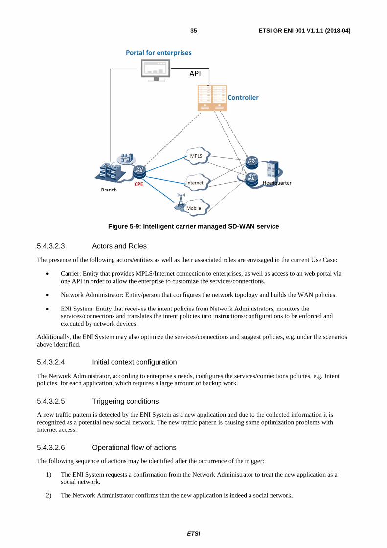
ETSI
ETSI GR ENI 001 V1.1.1 (2018-04)35
Figure 5-9: Intelligent carrier managed SD-WAN service
5.4.3.2.3 Actors and Roles
The presence of the following actors/entities as well as their associated roles are envisaged in the current Use Case:
• Carrier: Entity that provides MPLS/Internet connection to enterprises, as well as access to an web portal via one API in order to allow the enterprise to customize the services/connections.
• Network Administrator: Entity/person that configures the network topology and builds the WAN policies.
• ENI System: Entity that receives the intent policies from Network Administrators, monitors the services/connections and translates the intent policies into instructions/configurations to be enforced and executed by network devices.
Additionally, the ENI System may also optimize the services/connections and suggest policies, e.g. under the scenarios above identified.
5.4.3.2.4 Initial context configuration
The Network Administrator, according to enterprise's needs, configures the services/connections policies, e.g. Intent policies, for each application, which requires a large amount of backup work.
5.4.3.2.5 Triggering conditions
A new traffic pattern is detected by the ENI System as a new application and due to the collected information it is recognized as a potential new social network. The new traffic pattern is causing some optimization problems with Internet access.
5.4.3.2.6 Operational flow of actions
The following sequence of actions may be identified after the occurrence of the trigger:
1) The ENI System requests a confirmation from the Network Administrator to treat the new application as a social network.
2) The Network Administrator confirms that the new application is indeed a social network.
ETSI
ETSI GR ENI 001 V1.1.1 (2018-04)36
3) The ENI System identifies related policies and analyses past history looking for:
a) Policy violations before the identification of the new application.
b) Impact of the new application on network optimization.
4) The ENI System suggests the Network Administrator some changes to existing policies:
a) Alter existing policies e.g.: "Personal devices cannot access Facebook more than one hour per day" to "Personal devices cannot access social networks more than one hour per day", in order to include both Facebook and the new application, or
b) Add new policy e.g.: "All Social Network traffic have the lowest priority when accessing the Internet" to mitigate the access problems cause in the network by the new application when accessing the Internet.
5) The Network Administrator acknowledges the new policies and confirms the changes to the ENI System.
6) After confirmation, the ENI System provokes the enforcement of the new changes in policies by configuring appropriate network components.
5.4.3.2.7 Post-conditions
The new application is categorized and customized configuration is registered in the portal. The network traffic generated by different applications is routed to different paths according to the services/connections policies and application configuration.
After the changes to the network policies and devices configuration, the SD-WAN service is running under optimal conditions.
5.5 Assurance
5.5.1 Use Case #4-1: Network fault identification and prediction
5.5.1.1 Use case context
For a network device or a network service, performance and other problems generally exist before the equipment/service fails. It is important to proactively identify and forecast status of a device/service that is not performing as expected in order for network operation and maintenance management to be able to repair the service before customer requirements are violated. Such identification and predication will need network information to be collected.
This use case takes wavelength division service as an example, which collects information such as FEC_bef, input optical power, laser bias current, and other key factors that can be selected. The information collected can be used to keep track of wavelength division service over time and calculate the device statistics data in a specific time period such as average device downtime in the specified time window. These statistics data can be further used to detect wavelength division service anomaly or improve the accuracy rate for wavelength division KPI anomaly detection.
5.5.1.2 Description of the use case
5.5.1.2.1 Overview
The development of artificial intelligence and big data technologies has brought new chance to the network operation and maintenance management. Big data technology can be applied to analyse huge data generated from network operation and maintenance management, and deep learning method can be used to construct the intelligent network failure prevention (INFP) system, which can be a sub-system of intelligent analysing and prediction in the ENI system. INFP system can help operators to reduce the OPEX in the network and promote service quality.
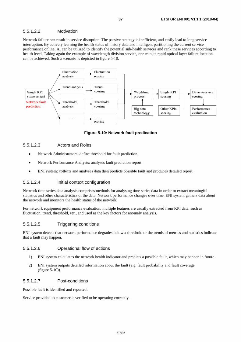
ETSI
ETSI GR ENI 001 V1.1.1 (2018-04)37
5.5.1.2.2 Motivation
Network failure can result in service disruption. The passive strategy is inefficient, and easily lead to long service interruption. By actively learning the health status of history data and intelligent partitioning the current service performance online, AI can be utilized to identify the potential sub-health services and rank these services according to health level. Taking again the example of wavelength division service, one minute rapid optical layer failure location can be achieved. Such a scenario is depicted in figure 5-10.
Figure 5-10: Network fault predication
5.5.1.2.3 Actors and Roles
• Network Administrators: define threshold for fault prediction.
• Network Performance Analysts: analyses fault prediction report.
• ENI system: collects and analyses data then predicts possible fault and produces detailed report.
5.5.1.2.4 Initial context configuration
Network time series data analysis comprises methods for analysing time series data in order to extract meaningful statistics and other characteristics of the data. Network performance changes over time. ENI system gathers data about the network and monitors the health status of the network.
For network equipment performance evaluation, multiple features are usually extracted from KPI data, such as fluctuation, trend, threshold, etc., and used as the key factors for anomaly analysis.
5.5.1.2.5 Triggering conditions
ENI system detects that network performance degrades below a threshold or the trends of metrics and statistics indicate that a fault may happen.
5.5.1.2.6 Operational flow of actions
1) ENI system calculates the network health indicator and predicts a possible fault, which may happen in future.
2) ENI system outputs detailed information about the fault (e.g. fault probability and fault coverage (figure 5-10)).
5.5.1.2.7 Post-conditions
Possible fault is identified and reported.
Service provided to customer is verified to be operating correctly.
ETSI
ETSI GR ENI 001 V1.1.1 (2018-04)38
5.5.2 Use Case #4-2: Assurance of Service Requirements
5.5.2.1 Use Case context
Nowadays, specific industries such as banking, energy or railroads use dedicated network infrastructures because it is the only way they can guarantee their specific requirements are met. These network infrastructures have huge costs in terms of planning and management, and take several months to be deployed. However, these industries would prefer to have Network Operators deploying and managing these private networks because that's not part of their core business. Moreover, during their lifetime operation, any change to the network infrastructure, no matter how small it is, is a cumbersome task due to the inherent complexity. To overcome this scenario, Network Operators can replace these dedicated networks by other virtualised solutions where pinning of virtual resources may be made to physical ones. In that virtualised context, one of those solutions is the use of the network slicing feature, if slices are capable of meeting the requested strict requirements. In addition, the use of proper resource allocation techniques would also help to solve the situation. However, this approach is very difficult to comply with, because current resource allocation techniques are not able to provide the required performance and assurance with context-awareness capabilities.
5.5.2.2 Description of the Use Case
5.5.2.2.1 Overview
When combining the network slices, slice/service prioritization and resource allocation concepts regarding a solution to the situation, it has to be considered that the dissemination of network slicing across network infrastructures will impact the virtual resource reservation and sharing since, unlike logical resources, physical resources cannot scale or migrate on demand.
NOTE: A network slice may encompass one or more than one services (mapping 1:1 or 1:n). When the mapping is 1:1, prioritization may either be designated by slice prioritization or by service prioritization.
In this Use Case, only a 1:1 mapping between slices and services is considered, and slice prioritization will be used.
Considering that each slice may be assigned for a specific type of service or service class, Network Operators will need to enhance their operational systems with the necessary carrier grade assurance capabilities to guarantee the continuous delivery of services characterized by strict requirements. These capabilities are needed to resolve resource allocation conflicts between competing network slices deployed on top of a shared infrastructure in an efficient and dynamic manner. In a shared infrastructure, being aware of a constantly changing context is vital for triggering a set of actions in a timely manner, e.g. scaling resources in order to meet network slice requirements or increase the priority for specific network slices.
A network domain may run several network slices where one of them provides an infrastructure to a specific industry, e.g. an Energy Provider company. This Energy Provider uses the network slices for vital applications that enable them to operate their core business. Because these applications have very strict network requirements, the Network Operator and the Energy Provider establish a customized SLA.
The current Use Case is further described by the following set of components and features.
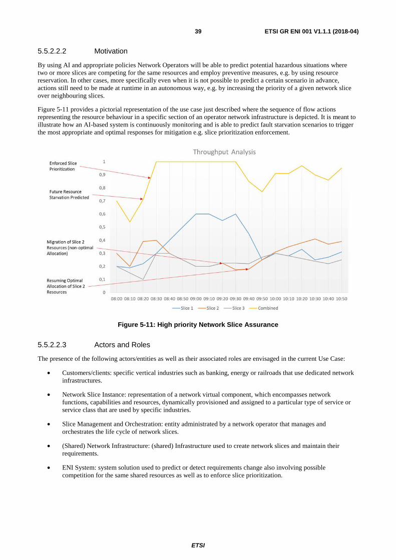
ETSI
ETSI GR ENI 001 V1.1.1 (2018-04)39
5.5.2.2.2 Motivation
By using AI and appropriate policies Network Operators will be able to predict potential hazardous situations where two or more slices are competing for the same resources and employ preventive measures, e.g. by using resource reservation. In other cases, more specifically even when it is not possible to predict a certain scenario in advance, actions still need to be made at runtime in an autonomous way, e.g. by increasing the priority of a given network slice over neighbouring slices.
Figure 5-11 provides a pictorial representation of the use case just described where the sequence of flow actions representing the resource behaviour in a specific section of an operator network infrastructure is depicted. It is meant to illustrate how an AI-based system is continuously monitoring and is able to predict fault starvation scenarios to trigger the most appropriate and optimal responses for mitigation e.g. slice prioritization enforcement.
Figure 5-11: High priority Network Slice Assurance
5.5.2.2.3 Actors and Roles
The presence of the following actors/entities as well as their associated roles are envisaged in the current Use Case:
• Customers/clients: specific vertical industries such as banking, energy or railroads that use dedicated network infrastructures.
• Network Slice Instance: representation of a network virtual component, which encompasses network functions, capabilities and resources, dynamically provisioned and assigned to a particular type of service or service class that are used by specific industries.
• Slice Management and Orchestration: entity administrated by a network operator that manages and orchestrates the life cycle of network slices.
• (Shared) Network Infrastructure: (shared) Infrastructure used to create network slices and maintain their requirements.
• ENI System: system solution used to predict or detect requirements change also involving possible competition for the same shared resources as well as to enforce slice prioritization.
ETSI
ETSI GR ENI 001 V1.1.1 (2018-04)40
5.5.2.2.4 Initial context configuration
The Network Slices associated to each dedicated network are created and configured according to the requirements agreed with customers and formally contracted by SLAs. All services are running with optimal resource allocation.
5.5.2.2.5 Triggering conditions
At a certain point in time, one slice reveals a considerable deviation from normal resource consumption patterns. Since this slice is deployed over a shared infrastructure where other slices and services are also provisioned, the abnormal behaviour may impact these other slices, including the one established for the Energy Provider.
5.5.2.2.6 Operational flow of actions
The following sequence of actions may be identified after the occurrence of the trigger:
1) The ENI System makes a simulation for the consumption of resources according to the detected spike.
2) The ENI System projection, predicts a resource starvation on a specific zone of the infrastructure that is supporting several network slices.
3) According to the contracted SLAs, the ENI System enforces slice prioritization to guarantee that network slices with strict requirements do not violate the contracted SLAs, since the option of allocating more resources to those slices is not feasible due to the lack of available resources on the specific zone.
4) With the increase of prioritization for one of the slices, one of lower priority starts suffering from resource starvation. To mitigate the impact, the ENI System makes use of dynamic resource allocation techniques and performs the migration of some resources to a temporary non-optimal location but that is able to better accommodate the network slice.
5) After the spike in resource consumption disappears, the ENI System triggers the optimal allocation of resources to the network slice blueprint that was standing before the resource migration; afterwards all services are running with optimal resource allocation.
5.5.2.2.7 Post-conditions
The dedicated networks resume normal operation according to contracted SLA.
6 Recommendations to ENI The requirements extracted from the Use Cases captured in the present document are specified in the Requirement document [i.6]. These requirements are divided into service requirements, functional requirements, and non-functional requirements. The service requirements are further sub-divided into: general requirements; service orchestration and management; network planning and deployment; network optimization; resilience and reliability; security and privacy. The functional requirements are further sub-divided into: data collection and analysis, policy management and data learning. The non- functional requirements are further sub-divided into: performance requirements, operational requirements and regulatory requirements.
The ENI architecture [i.7] will support all the requirements generated from the Use Cases.

ETSI
ETSI GR ENI 001 V1.1.1 (2018-04)41
Annex A: Bibliography ETSI GR ENI 003 (V0.1.3): "Experiential Networked Intelligence (ENI); Context-Aware Policy Modelling Gap Analysis".

ETSI
ETSI GR ENI 001 V1.1.1 (2018-04)42
Annex B: Authors & contributors The following people have contributed to the present document:
Rapporteur:
Dr. Yue Wang, Samsung R&D Institute UK
Other contributors:
Antonio Gamelas, Portugal Telecom
Bruno Parreira, Portugal Telecom
Chris Cavigioli, Intel Corp
Georgios Karagiannis, Huawei
Haining Wang, China Telecom
Jizhuang Zhao, China Telecom
John Strassner, Huawei
Mehrdad Shariat, Samsung R&D Institute UK
Shucheng (Will) Liu, Huawei
Weiping Xu, Huawei
Xiaojian Ding, Huawei
Yu Zeng, China Telecom

ETSI
ETSI GR ENI 001 V1.1.1 (2018-04)43
History
Document history
V1.1.1 April 2018 Publication


