Delft, University of Technology Engineering office of Public works Rotterdam
Interaction between plate and column buckling Master Thesis
Name: Alex van Ham Student number: 1306138 Email: [email protected]
12-1-2012


Alex van Ham Interaction between plate and column buckling 12 januari 2012
3
Graduation Committee
Chairman prof. ir. F.S.K. Bijlaard
Department of Structural Engineering, Steel Structures
Faculty of Civil Engineering and Geosciences
Delft University of Technology
Committee members ir. R. Abspoel
Department of Structural Engineering, Steel Structures
Faculty of Civil Engineering and Geosciences
Delft University of Technology
dr. ir. P.C.J. Hoogenboom
Department of Structural Engineering, Structural Mechanics
Faculty of Civil Engineering and Geosciences
Delft University of Technology
External committee member ir. J.H. Reusink
Senior consultant Bridges and Steel Structures
Engineering office Public Works Rotterdam
Secretary ir. L.J.M. Houben
Department of Structural Engineering, Road and Railway Engineering
Faculty of Civil Engineering and Geosciences
Delft University of Technology


Alex van Ham Interaction between plate and column buckling 12 januari 2012
5
Preface This master thesis has been written as the final part of my study Civil Engineering at Delft
University of Technology. My master is at the department of Structural Engineering and the
specialization is Steel and Timber Structures. Also an honours track has been done to include
courses on both Concrete Structures and Structural Mechanics.
My master thesis project is done at the Engineering Office of Public Works Rotterdam. They
offered me the opportunity to study the subject of plate buckling in steel structures. Their
main question at the Engineering Office was to provide insight in the Eurocode on plate
buckling (NEN-EN1993-1-5) and how it should be applied. This resulted in a tool which can
be used to check class 4 steel cross-sections. This question is combined with the subject of the
interaction of plate and column buckling which is a theoretical study.
I would like to thank the entire MSc graduation committee for their input and feedback.
Alex van Ham
Rotterdam, January 2012


Alex van Ham Interaction between plate and column buckling 12 januari 2012
7
Abstract Dimensioning and verification of steel structures is often governed by the demands for
stability and the plastic capacity of the material is not fully utilized. There are a several forms
of instability such as column buckling, lateral-torsional buckling and plate buckling.
Interaction of plate and column buckling has not been extensively studied before and that is
the main subject of this master thesis. In present verification codes in The Netherlands it is
allowed to separately calculate the effects of both and then combine them in a certain way.
Question is whether this is indeed correct. Analytical calculations have been done on an I-
column to derive the theoretical buckling load combining the effects of plate and column
buckling. In general the interaction is very small but for uneconomic cross-sections with a
large area of the web compared to the area of the flange this interaction can be large. The
numerical answer is not very relevant because the post-buckling behaviour of plate and
column buckling is totally different but the knowledge gained is more important. The most
important conclusion from the analytical calculation is that interaction is only present when
the number of half sine waves in the web is equal to the number of half sine waves in the
entire column.
Also calculations have been performed using a finite element method. Many cross-sections
have been considered and the general trend is that the bearing capacity according to the
verification regulations are closely related to the results from the finite element analysis. For a
certain type of cross-section the results are significantly different compared to the verification
regulations. This is for uneconomic cross-sections with a large area of the web compared to
the area of the flange. The difference can be up to 20% of the bearing capacity. This type of
cross-sections is not used very often because these would be very uneconomic but the
verification regulations overestimate the bearing capacity. In general a designer is free to
design any sort of structure. After that the structure should be verified for structural safety
using the regulations. These regulations should either provide the correct verification
regulations or inform that a certain type of structure is outside the scope of the regulations.
Neither is done in the current verification regulations. A formula is developed to calculate the
reduced bearing capacity for this type of cross-sections.
A probabilistic design has been done on an economic and an uneconomic type of cross-
section. The required safety was reached for the economic cross-section ( ) but for
the uneconomic cross-section ( ) the safety was not reached. No general conclusions
may be drawn because only two situations have been investigated but the difference is
striking. It confirms the unsafe nature of the verification regulations for the uneconomic
cross-sections.
A design recommendation has been made on how to design a class 4 cross-section. It is
shown that it is not efficient to add longitudinal stiffeners to the web when verification
regulations of the effective cross-section method are used. Only the effective area of the web
is increased which is in general small and for bending moments also close to the centre of
gravity.
A design tool has been developed which checks class 4 cross-sections according to the
verification regulations in NEN-EN1993-1-5. The tool can check I cross-sections as well as a
box or a cross-section. Longitudinal stiffeners to the web, through decks and concrete
toppings can be added.


Alex van Ham Interaction between plate and column buckling 12 januari 2012
9
Table of Contents Graduation Committee ............................................................................................................... 3
Chairman ................................................................................................................................ 3
Committee members .............................................................................................................. 3
External committee member .................................................................................................. 3
Secretary ................................................................................................................................. 3
Preface ........................................................................................................................................ 5
Abstract ...................................................................................................................................... 7
Table of Contents ....................................................................................................................... 9
Chapter 1: Introduction ............................................................................................................ 15
General introduction ............................................................................................................. 15
Objectives ............................................................................................................................. 15
Thesis outline ....................................................................................................................... 16
Chapter 2: Buckling ................................................................................................................. 19
Buckling ............................................................................................................................... 19
Rayleigh method .................................................................................................................. 23
Conventions in thesis ........................................................................................................... 23
Bernoulli assumptions ...................................................................................................... 23
Economic design .............................................................................................................. 23
Coordinate system ............................................................................................................ 23
Derivation column buckling ................................................................................................. 24
Derivation lateral torsional buckling .................................................................................... 26
Derivation plate buckling ..................................................................................................... 29
Chapter 3: Plate buckling in Eurocode ..................................................................................... 31
Effective cross-section method ............................................................................................ 31
Reduced stress method ......................................................................................................... 31
Design of a cross-section against plate buckling ................................................................. 32
Classes in NEN-EN1993-1-1 ............................................................................................... 35
Development of calculation tool .......................................................................................... 37
Chapter 4: Interaction between plate and column buckling ..................................................... 39
Stability of a flange .............................................................................................................. 40
Stability of a welded I-column under uniform compression ................................................ 41
Deflection shape as a sum of global and plate buckling behaviour ................................. 42
Determine equilibrium condition ..................................................................................... 43
Verification of the result .................................................................................................. 46
Results .............................................................................................................................. 47

Alex van Ham Interaction between plate and column buckling 12 januari 2012
10
Conclusion ........................................................................................................................ 52
Chapter 5: I-column according to the NEN-EN1993-1-1 and NEN6771 ................................ 53
Stability of a welded I-column under uniform compression ................................................ 53
According to NEN-EN1993-1-1 ...................................................................................... 53
According to NEN6771 .................................................................................................... 56
Chapter 6: I-column in FEM .................................................................................................... 59
Displacement control vs Force control ................................................................................. 60
Model description ................................................................................................................. 60
Single geometrical imperfections ..................................................................................... 61
Results .................................................................................................................................. 64
Class 4 profile with large flanges (flanges 500x25 mm and web 1500x15 mm) ............. 65
Class 4 profile with small flanges (flanges 150x15 mm and web 1500x15 mm) ............ 67
Sensitivity analysis ............................................................................................................... 68
Yield stress ....................................................................................................................... 68
Imperfections .................................................................................................................... 69
Chapter 7: Comparison of analytical, FEM and Eurocode results for I-column ...................... 71
General results ...................................................................................................................... 71
Influence ratio web to flange ................................................................................................ 72
Influence type of imperfections ............................................................................................ 75
Chapter 8: Probabilistic design on an economic and an uneconomic I-column ...................... 77
Probabilistic design in Ansys ............................................................................................... 77
Design variables ................................................................................................................... 77
Economic I-column .............................................................................................................. 80
Uneconomic I-column .......................................................................................................... 82
Conclusion ............................................................................................................................ 84
Chapter 9: Interaction between plate and lateral-torsional buckling ........................................ 87
Stability of a welded I-beam under uniform bending moment ............................................ 87
Initial deflection as a sum of lateral-torsional and plate buckling behaviour .................. 87
Determine equilibrium condition ..................................................................................... 88
Verification of the result .................................................................................................. 90
Results .............................................................................................................................. 90
Conclusion ........................................................................................................................ 93
Chapter 10: I-beam according to the Eurocode and NEN ........................................................ 95
Stability of a welded I-beam under uniform bending moment ............................................ 95
According to NEN-EN1993-1-1 ...................................................................................... 95
According to NEN6771 .................................................................................................... 97

Alex van Ham Interaction between plate and column buckling 12 januari 2012
11
Chapter 11: I-beam in FEM ..................................................................................................... 99
Displacement control vs Force control ................................................................................. 99
Model description ................................................................................................................. 99
Single geometrical imperfections ................................................................................... 100
Results ................................................................................................................................ 102
Economic class 4 profile (flanges 500x25 mm and web 1500x10 mm) ........................ 103
Uneconomic class 1 profile (flanges 500x25 mm and web 1500x50 mm) .................... 103
Sensitivity analysis ............................................................................................................. 104
Yield stress ..................................................................................................................... 104
Imperfections .................................................................................................................. 105
Chapter 12: Comparison of analytical, FEM and Eurocode results for I-beam ..................... 107
General results .................................................................................................................... 107
Influence ratio web to flange .............................................................................................. 107
Influence type of imperfections .......................................................................................... 108
Chapter 13: Conclusion, recommendations and future research ............................................ 109
Conclusions ........................................................................................................................ 109
Verification regulations .................................................................................................. 109
Theoretical buckling load ............................................................................................... 109
Interaction plate buckling and column buckling ............................................................ 109
Influence ratio web to flange .......................................................................................... 109
Imperfection shape in finite element model ................................................................... 110
Probabilistic design ........................................................................................................ 110
I-beam ............................................................................................................................. 110
Recommendations .............................................................................................................. 110
Validate conclusions ...................................................................................................... 110
Design recommendation for structural engineer ............................................................ 111
Future research ................................................................................................................... 111
References .............................................................................................................................. 113
List of figures ......................................................................................................................... 115
List of tables ........................................................................................................................... 119
Annex A: Derivation theoretical plate buckling load ............................................................. 121
Internal energy ................................................................................................................ 121
External energy .............................................................................................................. 123
Potential energy .............................................................................................................. 124
Differential equation ...................................................................................................... 125
Buckling load ................................................................................................................. 126

Alex van Ham Interaction between plate and column buckling 12 januari 2012
12
Annex B: Tool for checking class 4 I cross-sections ............................................................. 133
Guide to tool (in Dutch) ..................................................................................................... 133
Plooicontrole volgens NEN-EN1993-1-5 ...................................................................... 133
Tool .................................................................................................................................... 140
Validation of tool ............................................................................................................... 140
Validation of compressed plate with two stiffeners ....................................................... 140
I-column without stiffener .............................................................................................. 140
I-column with one stiffener ............................................................................................ 141
I-beam without stiffener ................................................................................................. 143
I-beam with one stiffener ............................................................................................... 145
Annex C: Analytical calculation of I-column under uniform compression without rotational
restraint ................................................................................................................................... 147
Stability of a welded I-column under uniform compression .............................................. 147
Deflection shape as a sum of global and plate buckling behaviour ............................... 148
Determine potential energy in the web .......................................................................... 149
Determine potential energy in the flange ....................................................................... 152
Total potential energy in the welded I-column .............................................................. 153
Virtual work done by the external forces on the web .................................................... 153
Virtual work done by the external forces on the flange ................................................. 154
Virtual work done by the external forces on the welded I-column ................................ 155
Determine equilibrium condition ................................................................................... 155
Verification of the result ................................................................................................ 159
Annex D: Analytical calculation of I-column under uniform compression including rotational
restraint ................................................................................................................................... 161
Determine potential energy in the web .......................................................................... 162
Determine potential energy in the flange ....................................................................... 165
Virtual work done by the external forces on the web .................................................... 166
Virtual work done by the external forces on the flange ................................................. 167
Determine equilibrium condition ................................................................................... 167
Verification of result ...................................................................................................... 169
Annex E: Finite element model for I-column ........................................................................ 171
Model using imperfections according to Eurocode ............................................................ 171
Main file ......................................................................................................................... 171
Calculation file ............................................................................................................... 171
Model using imperfections according to Eurocode using m=1.......................................... 174
Main file ......................................................................................................................... 174
Calculation file ............................................................................................................... 175

Alex van Ham Interaction between plate and column buckling 12 januari 2012
13
Model using imperfections according to lowest buckling load .......................................... 178
Main file ......................................................................................................................... 178
Calculation file ............................................................................................................... 178
Model for probabilistic design ........................................................................................... 181
Main file ......................................................................................................................... 181
Single calculation file ..................................................................................................... 181
Annex F: Verification and results finite element model for I-column ................................... 187
Verification of the model ................................................................................................... 187
Linear elastic calculation ................................................................................................ 187
Plastic calculation ........................................................................................................... 188
Theoretical buckling load ............................................................................................... 188
Mesh refinement ............................................................................................................. 189
Load step reduced ........................................................................................................... 190
Simple checks in FEM ................................................................................................... 191
Results ................................................................................................................................ 192
Annex G: Analytical calculation of I-beam under uniform bending moment without rotational
restraint ................................................................................................................................... 203
Stability of a welded I-beam under uniform bending moment .......................................... 203
Initial deflection as a sum of lateral-torsional and plate buckling behaviour ................ 203
Total potential energy in the welded I-beam .................................................................. 204
Virtual work done by the external forces on the web .................................................... 205
Virtual work done by the external forces on the flange ................................................. 208
Virtual work done by the external forces on the welded I-beam ................................... 210
Determine equilibrium condition ................................................................................... 210
Verification of the result ................................................................................................ 213
Annex H: Finite element model for I-beam ........................................................................... 215
Model using imperfections according to Eurocode ............................................................ 215
Main file ......................................................................................................................... 215
Calculation file ............................................................................................................... 215
Model using imperfections according to Eurocode using m=1.......................................... 219
Main file ......................................................................................................................... 219
Calculation file ............................................................................................................... 219
Annex I: Verification and results finite element model for I-beam ....................................... 225
Verification of the model ................................................................................................... 225
Linear elastic calculation ................................................................................................ 225
Plastic calculation ........................................................................................................... 225

Alex van Ham Interaction between plate and column buckling 12 januari 2012
14
Mesh refinement ............................................................................................................. 226
Load step reduced ........................................................................................................... 227
Simple checks in FEM ................................................................................................... 227
Results ................................................................................................................................ 228
Annex J: Calculation tool ....................................................................................................... 235
Alex van Ham Interaction between plate and column buckling 12 januari 2012
15
Chapter 1: Introduction
General introduction In modern days structural engineers are often challenged by architects to design more slender
and more challenging steel structures. Therefore, not always the most economic or common
construction is chosen which creates challenges for structural engineers. To be able to design
uncommon constructions it is necessary to have a proper understanding of the structural
behaviour of those structures.
One important aspect of this is the concept of plate buckling. The new Eurocode on plate
buckling (NEN-EN1993-1-5, 2006) recommends the use of the effective width method. There
is an issue which needs to be investigated. This is an I-column with small flanges compared to
the size of the web in which it is assumed that the flanges fully support the web against plate
buckling. NEN-EN1993-1-5 prescribes no requirements for the flanges to be able to fully
support the web. It is assumed that the stability of the flanges is covered in the checks on
column buckling and lateral-torsional buckling. The question is whether the flanges can
indeed be seen as stiff supports for the web no matter what dimensions are chosen.
Van der Burg (2011) has done research on this subject and calculated an I-column for a
certain configuration according to the NEN-EN1993-1-5 and compared these results to the
collapse load according to Ansys using a geometrical and physical non-linear model. From
that it was concluded that there is no additional requirement necessary for flanges of an I-
column. However, no analytical calculations have been done which provide insight in the
interaction of column buckling and plate buckling. Also no calculations have been done using
a bending moment instead of axial compression which provides information about the
interaction of lateral-torsional buckling and plate buckling.
Plate buckling is a complicated subject in NEN-EN1993-1-5. The Engineering Office of
Public Works of Rotterdam is in need of a tool to calculate plate buckling according to the
NEN-EN1993-1-5. The verification rules are not clearly specified in the regulations and the
procedure is quite cumbersome. The NEN-EN1993-1-5 does not clearly prescribe why some
rules are needed and what the background is according to structural mechanics. This
information is required about the background of the design rules to accommodate the design
checks for situations which are not exactly prescribed in the NEN-EN1993-1-5.
Objectives Therefore the purpose of this master thesis is as follows:
1. Gain insight in the background of plate buckling according to the NEN-EN1993-1-5
using literature.
2. Produce a versatile tool in Mathcad to check plate buckling for I- and box-profiles
according to the NEN-EN1993-1-5. A check of this tool should also be performed.
3. Produce guidelines about whether flanges of an I-column are stiff or not using
analytical solutions and also FEM-analyses. These should be compared to the results
from NEN-EN1993-1-5.
Working in this way will be a natural way to get familiar with the NEN-EN1993-1-5 on plate
buckling because first literature is studied and then the knowledge gained is applied in

Alex van Ham Interaction between plate and column buckling 12 januari 2012
16
creating a tool. After that phase there should be a proper understanding of the NEN-EN1993-
1-5 and then an investigation can be set up on the required stiffness of flanges.
Thesis outline Chapter 1 gives a general introduction of the subject of this thesis. The problem definition is
stated and an outline is given of this thesis.
Chapter 2 is a general introduction on the subject of buckling as a short introduction for the
reader that is not familiar with the subject of buckling. The conventions used in this thesis are
described such as the coordinate system. Also the derivations for column buckling, lateral-
torsional buckling and plate buckling are given.
Chapter 3 describes how plate buckling is dealt with in the NEN-EN1993-1-5. The difference
between the effective cross-section method and the reduced stress method is explained. A
general design recommendation is made for class 4 cross-sections. A calculation tool has been
developed which is necessary to check cross-sections according to the NEN-EN1993-1-5.
This tool is explained here.
Chapter 4 describes the buckling behaviour of a welded I-column under uniform compression.
This is done for a theoretical structure that has no imperfections and no residual stresses.
Therefore the theoretical buckling load is the result of this derivation. This theoretical
buckling load is for the interaction of column buckling and plate buckling.
Chapter 5 provides the verification method for a welded I-column according to the regulations
in the Netherlands as they are now and as they were before. The difference is explained.
Chapter 6 is about the finite element analysis of the welded I-column. Different forms of
imperfections are investigated and the interaction between column buckling and plate
buckling is studied.
Chapter 7 sums up the conclusions for the welded I-column. General conclusions are drawn
based on the results of the finite element analysis. The interaction of plate buckling and
column buckling is examined here. It is shown that the ratio of the area of the web to the ratio
of the area of the flange is important for the load bearing capacity.
Chapter 8 is about the probabilistic analysis that is done for two different cross-sections. An
economic cross-section is compared to an uneconomic cross-section. The safety of both is
investigated and especially the difference is important.
Chapter 9 describes the buckling behaviour of a welded I-beam under uniform bending
moment. This is done for a theoretical structure that has no imperfections and no residual
stresses. Therefore the theoretical buckling load is the result of this derivation. This buckling
load is the theoretical buckling load for the interaction of lateral-torsional buckling and plate
buckling.
Chapter 10 provides the verification method for a welded I-beam according to the regulations
in the Netherlands as they are now and as they were before.

Alex van Ham Interaction between plate and column buckling 12 januari 2012
17
Chapter 11 is about the finite element analysis of the welded I-beam. Different forms of
imperfections are investigated and the interaction between lateral-torsional buckling and plate
buckling is studied.
Chapter 12 sums up the conclusions for the welded I-beam. General conclusions are drawn
based on the results of the finite element analysis. The interaction of plate buckling and
lateral-torsional buckling is examined here. It is shown that the ratio of the area of the web to
the ratio of the area of the flange is important for the load bearing capacity.
Chapter 13 provides a general conclusion about the interaction forms of buckling that exist.
Also recommendations are done for the future whether regulations should be changed
concerning the interaction of buckling. Also recommendations are done for future research on
this subject.
Annex A to Annex J contain the analytical calculations, the finite element analyses and the
calculation tool.


Alex van Ham Interaction between plate and column buckling 12 januari 2012
19
Chapter 2: Buckling Plate buckling is a form of buckling in which a plated structure buckles if the width to
thickness ratio is large. Buckling means a loss of stability so first the concept of stability and
buckling is explained before plate buckling is introduced. This is only a general introduction.
Literature provides more information (Vrouwenvelder, 2003).
Buckling Buckling is a phenomenon which occurs in structures which are stiff in the loaded direction
and slender in another direction. Initially equilibrium is stable but when the load is increased
there is a sudden increase in deflection in loading direction due to a displacement in the
slender direction. This is at the location of the bifurcation point. For structural behaviour this
is a very important point because it is for slender constructions often governing and the plastic
or elastic cross-sectional capacity is not reached. When buckling does not occur at a certain
load level, a structure is considered stable.
There are some important differences between the behaviour of shells, plates and columns.
Perfect Euler columns have a slight post buckling strength. For common dimensions this is
generally around 3% for an out of plane deflection of 20% of the length of the column.
(Vrouwenvelder, 2003) So for Euler columns the buckling load is considered to be the load
bearing capacity. However, if buckling occurs, the load can still be carried and large
deflections occur which is a warning for the users. Imperfections and residual stresses change
the behaviour from the theoretically perfect column. Lateral deflections occur at a lower
loading than the buckling load and the lateral deformation increases until the buckling load is
reached or the section fails due to large stresses.
Figure 1: Buckling of shells, columns and plates for geometrical (non)linear and physically linear behaviour
(University of Ljubljani, 2011)
Shells have a very efficient way of carrying loading but buckling is a sudden occurrence and
is immediately the end of the load bearing capacity. This is a dangerous occurrence because
the load bearing capacity is immediately lost when buckling occurs. Also, because of

Alex van Ham Interaction between plate and column buckling 12 januari 2012
20
imperfections and residual stresses, the theoretical buckling load cannot be reached. Shells are
not considered in this thesis so no further information is supplied.
Plates have an additional post-buckling strength. A plate can buckle and the load can be
increased further until final collapse. This difference may be quite large and can be exploited
in structural calculations. Small imperfections do not have a large influence on the behaviour
like it is the case with shells. Von Karman has developed a formula to take account of the
post-buckling strength and is derived in the following way.
The maximum stress on a plate is given by the following formula which will be derived later.
(2.1)
If the critical stress is replaced by the yield stress in equation (2.1) the effective width can be
calculated.
(2.2)
These two equations result in the following relation.
(2.3)
Therefore the effective width is given by the following relation.
(2.4)

Alex van Ham Interaction between plate and column buckling 12 januari 2012
21
Figure 2: Effective width of a compressed plate (University of Ljubljani, 2011)
The reduction factor can be written in the following way.
(2.5)
Therefore the effective width can be calculated in the following way:
(2.6)
This is based on a theoretic case. Tests by Winter resulted in a slightly different formula
which is:
(2.7)
However, for structures that are loaded by a variable loading, this post-buckling strength
cannot be utilized. If a variable loading is causing the plate to buckle and the load is removed,
the plate will have large plastic deformations and will not return to its original shape. If the
variable load is applied and removed numerous times, the post-buckling strength cannot be
utilized anymore. This is caused by significant secondary bending stresses near edges of the
web and at discontinuities like transverse and longitudinal stiffeners. They cause cumulative

Alex van Ham Interaction between plate and column buckling 12 januari 2012
22
fatigue damage to the welded structure and therefore the post-buckling strength cannot be
utilized. This is called web-breathing.
In this thesis there is often a mention of local, global and lateral-torsional buckling. A clear
definition is presented to guide the reader.
Global buckling: Global buckling or column buckling (Figure 3) is buckling of an entire
member out of plane under uniform compression. This is a lateral deflection.
Figure 3: Global buckling or column buckling (FEA Optimization, 2011)
Local buckling: Local buckling or plate buckling (Figure 4) is buckling of a single plate in
one or multiple sines where the edges do not have a displacement out of plane.
Figure 4: Plate buckling or local buckling for a ratio of (displacement out of plane plotted)
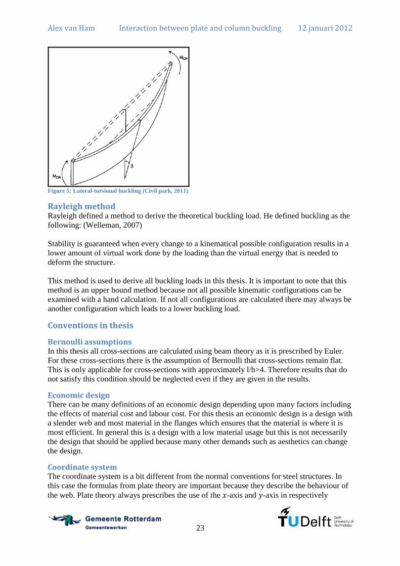
Lateral-torsional buckling: Lateral-torsional buckling (Figure 5) is buckling of an entire
member due to a bending moment. This is a lateral deflection combined with a torsional
rotation.
Alex van Ham Interaction between plate and column buckling 12 januari 2012
23
Figure 5: Lateral-torsional buckling (Civil park, 2011)
Rayleigh method Rayleigh defined a method to derive the theoretical buckling load. He defined buckling as the
following: (Welleman, 2007)
Stability is guaranteed when every change to a kinematical possible configuration results in a
lower amount of virtual work done by the loading than the virtual energy that is needed to
deform the structure.
This method is used to derive all buckling loads in this thesis. It is important to note that this
method is an upper bound method because not all possible kinematic configurations can be
examined with a hand calculation. If not all configurations are calculated there may always be
another configuration which leads to a lower buckling load.
Conventions in thesis
Bernoulli assumptions In this thesis all cross-sections are calculated using beam theory as it is prescribed by Euler.
For these cross-sections there is the assumption of Bernoulli that cross-sections remain flat.
This is only applicable for cross-sections with approximately l/h>4. Therefore results that do
not satisfy this condition should be neglected even if they are given in the results.
Economic design There can be many definitions of an economic design depending upon many factors including
the effects of material cost and labour cost. For this thesis an economic design is a design with
a slender web and most material in the flanges which ensures that the material is where it is
most efficient. In general this is a design with a low material usage but this is not necessarily
the design that should be applied because many other demands such as aesthetics can change
the design.
Coordinate system The coordinate system is a bit different from the normal conventions for steel structures. In
this case the formulas from plate theory are important because they describe the behaviour of
the web. Plate theory always prescribes the use of the -axis and -axis in respectively
Alex van Ham Interaction between plate and column buckling 12 januari 2012
24
longitudinal and transverse direction of a plate. The -axis is the direction out of plane. The
axis system is defined so that the web has this coordinate system as given in Figure 6. The
moments of inertia are therefore defined as:
This is in contradiction to the normal conventions for steel structures and mechanics.
However, this is much more convenient for the derivations of the buckling loads.
xz
y
Figure 6: Coordinate system 1
In several cases it is more convenient to define the axis system at the connection of the top
flange and the web as given in Figure 7. This is mainly necessary because the behaviour of
the web can then be described using a sine-function for the web in transverse direction. The
definitions for the moments of inertia as above are still valid. The shift of the axis should not
be included when calculating those moments of inertia.
xz
y
Figure 7: Coordinate system 2
Furthermore are compressive stresses in the theoretical buckling analyses defined as positive.
This is done as mostly only compressive stresses are present and those stresses are the
destabilizing component.
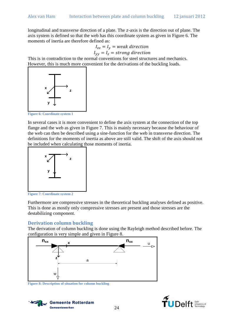
Derivation column buckling The derivation of column buckling is done using the Rayleigh method described before. The
configuration is very simple and given in Figure 8.
a
nxx nxxx
z
w
u
Figure 8: Description of situation for column buckling

Alex van Ham Interaction between plate and column buckling 12 januari 2012
25
The energy that is needed to deform the structure into a certain configuration is the following:
(2.8)
However, just before buckling there is already energy in the structure due to axial strain. This
is equal to the energy due to axial strain after buckling because there is no increase in loading
from just before buckling to just after buckling. The energy due to axial strain before buckling
is:
(2.9)
Therefore the energy that is additionally added in the structure due to a change in
configuration is:
(2.10)
Later a relationship (equation (14.15)) is derived to explain the shortening at the point of
loading due to the lateral deflection. The result is the following:
(2.11)
Therefore the term describing the virtual work done by the point load is the following:
(2.12)
Now the energy and the virtual work equations are known a possible kinematic configuration
is chosen. For global buckling it is known that buckling will be in the form of a sine so this is
applied here. Any other configuration will lead to a higher buckling force. is an integer
which gives the number of half sine waves in the deflection field.
(2.13)
Applying the derivative of equation (2.13) to equation (2.10) gives the energy in the structure:
(2.14)
Applying the derivative of equation (2.13) to equation (2.12) gives the virtual work done on
the structure:
(2.15)
Now the energy in the structure is equated to the virtual work done and that results
in:

Alex van Ham Interaction between plate and column buckling 12 januari 2012
26
(2.16)
The final result is:
(2.17)
The lowest buckling load is obtained when is applied resulting in the well known
formula for buckling, which is also known as the Euler buckling load:
(2.18)
Derivation lateral torsional buckling Lateral-torsional buckling is the loss of stability due to a bending moment in a combined
lateral deflection ( ) and torsional rotation (
). The derivation is a modified version of (Vrouwenvelder, 2003). The general
displacement field in a double symmetric cross-section, assuming small rotations, can be
described as:
(2.19)
a
Mx
y
v
uM
θ
zy
w
v
Figure 9: Description of situation for lateral-torsional buckling
The energy in the structure is defined as before but with two additional terms describing the
free rotation (Saint Venant torsion) and the restrained warping.
(2.20)
The resistance against the free rotation is: (Hoogenboom, 2010)
(2.21)
The resistance against warping for I cross-sections is: (Hoogenboom, 2010)
(2.22)
The result of this integral is the following:

Alex van Ham Interaction between plate and column buckling 12 januari 2012
27
(2.23)
The virtual work done is the displacement at the end of the beam multiplied by the stress in
that certain point.
(2.24)
The stress in the fibre can be described with the following relation:
(2.25)
Inserting the equations for and results in:
(2.26)
Expanding of this results into:
(2.27)
Terms with or result in 0 for symmetric cross-sections when integrated over the height
of the section. Therefore only one term is non zero. Integration of over and is the
same as .
(2.28)
Evaluating this will result in the following which is only valid for . If this is not the
case, the result is zero.
(2.29)
Now the equation ( ) can be obtained which gives the lateral-torsional buckling
moment.
(2.30)
However, this equation cannot be solved because it is dependent on both and . Therefore
the values of and need to be such that the bending moment is minimum. The summation

Alex van Ham Interaction between plate and column buckling 12 januari 2012
28
is not included anymore because the terms are only valid for . Therefore the derivatives
with respect to and are taken and equated to zero.
(2.31)
The derivative to is:
(2.32)
These equations need to be written in matrix notation and can then be solved by equating the
determinant to zero. This will give the non-trivial solutions to the equation. This will result in
a matrix that looks like this where are non-zero terms:
(2.33)
The determinant will be zero when only one value of is used. Any other result using
multiple values of will result in an average buckling stress. Therefore the matrix can be
written as:
(2.34)
The determinant of equation (2.34) equated to zero is the following:
(2.35)
This is only valid for as stated before so all are changed to and the equation is
solved for .
(2.36)
Now it is easily seen that the lowest lateral-torsional buckling moment will be obtained for
. This gives the well known formula:
(2.37)
When the warping of the cross-section is not prevented this will result in the
formula that is generally used:
(2.38)

Alex van Ham Interaction between plate and column buckling 12 januari 2012
29
Derivation plate buckling Before the interaction of plate buckling and column buckling is derived, first the derivation of
the plate buckling load is presented. This is a modification of the derivation as it is presented
in (Abspoel & Bijlaard, 2005). An energy method is applied to calculate the buckling
behaviour. The entire derivation is presented in Annex A and here only the general principle
and the results are explained.
The aim is to determine the buckling load of a rectangular plate under a uniform loading from
one side as presented in Figure 10.
b
a
nxx nxxx
y
w
w
u
v
Figure 10: Description of situation for plate buckling
In a flow chart (Figure 11) the steps are given that will result in the buckling load.
Figure 11: Derivation of the plate buckling load
The entire derivation is presented in Annex A and that will result in a buckling load of:
(2.39)
The aspect ratio of a plate is defined as:
(2.40)
The buckling factor is defined as:
(2.41)
Internal energy infinitesimal
element
External energy infinitesimal
element
Potential energy
equation
Differential equation
Expected deflection
shape
Determine bending energy
Determine external work
done
Equate to find buckling load

Alex van Ham Interaction between plate and column buckling 12 januari 2012
30
The value of can be all real and positive integers so all buckling modes of the steel plate
are given by this equation. The value of is the amount of half-sine waves in a steel plate
when it buckles. In Figure 12 the buckling mode with and is presented.
Figure 12: Plate buckling shape for and .
The buckling factor is dependent on the aspect ratio of the plate and the number of half sine
waves and this can be plotted in a graph as done in Figure 13.
Figure 13: Buckling factor as a function of the aspect ratio for uniform compression
From Figure 13 it is clear that the buckling factor is 4 except when the aspect ratio is smaller
than 1 because then the buckling load is higher.
0
1
2
3
4
5
6
7
8
0 1 2 3 4 5 6
bucklin
g f
acto
r k [-]
aspect ratio α [-]
m=1
m=2
m=3
m=4
m=5
m=6

Alex van Ham Interaction between plate and column buckling 12 januari 2012
31
Chapter 3: Plate buckling in Eurocode The NEN-EN1993, a part of the Eurocode, is the standard for the verification of steel
structures in Civil Engineering in The Netherlands since 31st of March 2010. Before the NEN-
EN1993 was introduced, the NEN6770, a part of the TGB, was the standard in The
Netherlands. However, because of uniformity across Europe, a new standard was developed.
The NEN-EN1993 is an accumulation of design rules from different standards from the
participating countries combined with research results from the last years. In some cases, the
mechanical background is completely left out and only some formulas are supplied which
have been fitted to test results. A good engineer does not calculate always according to the
rules as they are but knows the mechanical background so he can make a proper judgement
whether a certain formula is applicable or not in a specific situation.
In the Eurocode 3 (NEN-EN1993) the structural verification of steel structures is described. In
particular in NEN-EN1993-1-5 the structural verification of plated structures are dealt with
for structural applications. This standard is a complicated standard because the mechanical
background is sometimes lost. Literature is available to guide an engineer in calculating plate
buckling. Relevant examples are Beg et al. (2010), Johansson et. al. (2007) and Van der Burg
(2011).
NEN-EN1993-1-5 has two ways for dealing with plate buckling. The recommended way is to
use the effective cross-section method and the other is the reduced stress method. Both start
with the same calculation which is to calculate the reduction factors for the individual
elements based on the width to thickness ratio and the stress distribution for each individual
element.
Effective cross-section method The effective cross-section method reduces each section with its own reduction factor. The
result is a new, smaller cross-section which is then utilized as a class 3 cross-section. This
means that an elastic cross-sectional verification has to be done. All verifications are done
using the new effective cross-section. In this case the weakest link is not governing and it is
assumed to be a parallel system. This method allows the plate to buckle and therefore utilizes
the post buckling strength that is available. Therefore this is the recommended method
because the largest possible strength is used.
Figure 14: The effective cross-section method for axial compression (NEN-EN1993-1-5, 2006)(p. 14)
Reduced stress method The reduced stress method also determines the reduction factors for all individual elements.
Then the cross-section is used as the gross section but the yield stress is reduced by the largest
reduction factor. All verifications are done using a lower allowable stress with the gross

Alex van Ham Interaction between plate and column buckling 12 januari 2012
32
cross-section. This is an elastic cross-sectional verification. The element with the largest
reduction factor is governing and all other elements are not fully utilized. Therefore the
weakest link is governing as it is seen as a serial system. This method does not allow the
governing plate to buckle and therefore does not utilize the post buckling strength that is
available. This method is therefore not the recommended method. However, in the case of
fatigue it is recommended to use this method because buckling of the plate causes significant
secondary bending stresses in the welds. Repeated loading and unloading will result in fatigue
damage because of those secondary bending stresses. This effect is called web breathing.
Figure 15: Analogy to effective cross-section method (left, parallel system) and reduced stress method (right, serial
system) (Stichting CUR, 1997)
Design of a cross-section against plate buckling Designing a cross-section against plate buckling used to be done according to the NEN6771.
This method recommends and explains the reduced stress method properly and the effective
cross-section method was not frequently applied. Now the NEN-EN1993-1-5 is applicable for
the verification of steel structures the effective cross-section method is recommended. The
main design issues are discussed here because especially the design of the web is significantly
different.
Using the reduced stress method in general the web is decisive for the strength of the entire
cross-section. If the web is very slender, the flanges may not be exploited up to the yield
strength. Applying a longitudinal stiffener will result in a higher reduced stress that may be
applied and therefore the flanges can have a much higher capacity.
Using the effective cross-section method the web is not decisive for the strength of the entire
cross-section. If the web is very slender, no reduction of the flanges is needed and they are
fully exploited. Applying a longitudinal stiffener will only result in a larger effective part of
the web but the web is in general small compared to the flanges so the additional capacity is
only small.
This reasoning can be clarified with a theoretical example. In Figure 16 a theoretical cross-
section is analyzed for axial compression. The case without a stiffener and with a stiffener is
examined using both methods. The areas and reduction factors are given.

Alex van Ham Interaction between plate and column buckling 12 januari 2012
33
ρw=0,2
Aw=0,25xA
ρw=0,8
Af=0,375xA
Aw=0,25xA
ρf=1,0
Af=0,375xAAf=0,375xA
Af=0,375xA
Figure 16: Cross-section for theoretical case between reduced stress and effective cross-section method
For the reduced stress method the axial capacity can be determined using:
(3.1)
The capacity using the effective cross-section method can be determined using:
(3.2)
Applying those formulas to the cross-section of Figure 16 gives the results as presented in
Table 1.
Without a stiffener With one stiffener
Reduced stress method (NEN6771)
Effective cross-section method
(NEN-EN1993-1-5)
Table 1: Results using the reduced stress and the effective cross-section method
It is immediately clear that the stiffener gives an increased capacity using the reduced stress
method of 300%. However, for the effective cross-section method the increase is only 18,8%.
This shows the difference between both methods and it is clear that in the NEN6771 using the
reduced stress method a stiffener is extremely effective to increase the axial capacity.
Applying the NEN-EN1993-1-5 the stiffener is probably not the most economic solution
because the increase is only small for a quite labour intensive handling. It would probably be
more economic to just increase the area of the flanges.
Some general remarks are given for consideration when designing a cross-section using the
effective cross-section method.
For the effective cross-section method stiffeners to the web are not very useful for the
static strength against axial compression and bending moments. In general the web is
slender and a stiffener only increases the area of the web that is effective. For axial
compression this is usually a small increase of the area and for bending moments the
material is close to the centre of gravity resulting in a small increase of the effective
section modulus.
It would be much more useful to apply larger flanges because the costs of adding a
stiffener are in general high in developed countries.

Alex van Ham Interaction between plate and column buckling 12 januari 2012
34
Fatigue loading can influence the design of the web. If variable loading is present, the
effect of web breathing should be examined and for slender webs a reduced stress
method should be applied. (NEN-EN1993-2, 2007)
Shear force influences the design of the web. The shear force is carried by the web and
the web should be designed for that including the effect of shear buckling.
Flange-induced buckling influences the design of the web. Depending on the area of
the flanges, the web needs a minimum thickness to withstand the inward forces of the
flange in bending.
Figure 17: Design of a class 4 cross-section
In Figure 17 a very simple design procedure is given for a class 4 cross-section. This can be
applied in many situations to get very quickly to approximately the right dimensions of the
cross-section. The interaction formulas in the NEN-EN1993-1-5 are based on second order
geometric forces. It would also be possible to estimate the buckling factor and increase the
first order forces by that factor. According to the NEN-EN1993-1-5 there is no interaction
check necessary when the shear force is 50% of the shear force capacity including the effects
of shear buckling. Therefore the web should be designed using twice the design shear force.
Then the slenderness of the flanges should be calculated such that they fit just into class 3. A
higher class would not be beneficial because a plastic design is not allowed using the effective
cross-section method. A lower class would result in a reduction of the effective area of the
flange and is only recommended when column buckling or lateral-torsional buckling may be a
decisive problem. The area of the flanges can be determined using the bending moments in
both directions and the axial force. This should be based on an elastic calculation of the
stresses using only the flanges. The small beneficial effect of the effective web is ignored and
could be exploited for the verification calculation.
(3.3)
Now the flanges and web are designed the web should be checked for flange induced
buckling. If the web is too slender, the web should be changed. If the height of the web is
Estimate geometric second order design
forces
Decide on yield stress of the material
Determine web based on twice the design shear
force including the effect of shear buckling
If the web is also subject to torsional loading,
these should be included in the determination
before.
Determine maximum slenderness of flanges
such that they are class 3 or higher
Calculate flanges so they can carry the design
bending moment (strong and weak direction) and
axial load elastically
Check web for flange induced buckling (if not satisfied, redesign web
based on twice the design shear force)
Take into account the effect of web breathing
and fatigue design if relevant

Alex van Ham Interaction between plate and column buckling 12 januari 2012
35
changed, also the area of the flanges changes. When this is all done, this is sufficient for a
preliminary static design. If there is a large variable loading, also a fatigue preliminary design
should be applied.
Classes in NEN-EN1993-1-1 NEN-EN1993-1-1 has defined classes to internal and external compression elements that
indicate whether the full plastic capacity, an elastic capacity or a reduced elastic capacity
needs to be used. The limit for internal elements under pure compression, e.g. a web, is a ratio
of to ensure class 3 behaviour according to table 5.2 in NEN-EN1993-1-1. However, if a
ratio of
is inserted into the plate buckling formula this results into a effective cross-
section of 95% as shown in the calculation below.
b
a
nxx nxxx
y
w
w
u
v
Figure 18: Plate under uniform axial compression
The factor is dependent on the yield stress:
(3.4)
The slenderness for plate buckling is defined as follows.
(3.5)
In this formula the critical plate buckling stress can be inserted.
(3.6)
The relevant numbers can be applied to the equation resulting into a slenderness.
(3.7)
Alex van Ham Interaction between plate and column buckling 12 januari 2012
36
Now the formula for the reduction of the cross-section is as follows for internal compression
elements. This is the same as the Winter formula written in a slightly different way.
(3.8)
Applying the numerical figures to this equation results in:
(3.9)
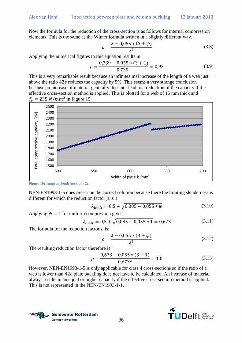
This is a very remarkable result because an infinitesimal increase of the length of a web just
above the ratio reduces the capacity by 5%. This seems a very strange conclusion
because an increase of material generally does not lead to a reduction of the capacity if the
effective cross-section method is applied. This is plotted for a web of 15 mm thick and
in Figure 19.
Figure 19: Jump at slenderness of
NEN-EN1993-1-5 does prescribe the correct solution because there the limiting slenderness is
different for which the reduction factor is 1.
(3.10)
Applying for uniform compression gives:
(3.11)
The formula for the reduction factor is:
(3.12)
The resulting reduction factor therefore is:
(3.13)
However, NEN-EN1993-1-5 is only applicable for class 4 cross-sections so if the ratio of a
web is lower than plate buckling does not have to be calculated. An increase of material
always results in an equal or higher capacity if the effective cross-section method is applied.
This is not represented in the NEN-EN1993-1-1.
1500
1600
1700
1800
1900
2000
2100
2200
2300
2400
2500
500 550 600 650 700
Tota
l com
pre
ssiv
e c
apaic
ty [
kN
]
Width of plate b [mm]

Alex van Ham Interaction between plate and column buckling 12 januari 2012
37
Therefore the calculation of NEN-EN1993-1-5 seems to be correct whereas the assumption of
class 3 behaviour for for internal compression elements is not consistent with the design
of plated structures.
Development of calculation tool The Engineering Office of Public works of Rotterdam is in need of a tool to calculate class 4
cross-sections according to the NEN-EN1993-1-5. The procedure in the NEN-EN1993-1-5 is
very cumbersome and is difficult to do quickly and correctly if this is not done on a regular
basis. Therefore a tool is needed to check an I cross-section. They are looking for an
extremely versatile tool which can be used for nearly all class 4 cross-sections. This means
that there should be several possibilities available:
0, 1 or 2 flat longitudinal stiffeners in the web
A fictitious plate at the top or at the bottom of the girder (e.g. a concrete deck)
A trough plate at the top or at the bottom of the girder (e.g. a steel deck)
Another requirement is that there should be several types of loading and also combinations
possible:
Axial compression or tension
Bending moment in the stiff direction
Shear force
Transverse load introduction
This means that there are many configurations possible. The tool is presented in Annex B and
the explanation of the tool is also in Annex B in Dutch. Dutch is the language used at the
engineering office so is also most suitable for the explanation of the procedure. A short
outline is presented here in English to guide the reader.
The input is an I cross-section which can have four different flanges. (topleft, topright,
lowerleft and lowerright) This does not mean that the tool is only applicable for an I cross-
section because a box girder may be cut in two and then it is similar to an I cross-section.
Also a -girder can be used when it is split in two.
There is one main advantage of the NEN-EN1993-1-5 that is applied in the tool. The NEN-
EN1993-1-5 allows the resistance of the cross-section to be determined without any
knowledge of the applied loading for I and box cross-sections. This was not true in the old
NEN6771 codes where the loading configuration influences the resistance of the cross-
section. The NEN-EN1993-1-5 allows the calculation of the axial resistance based on only the
geometry and axial compression. Then the resistance against bending moments can be
calculated using the geometry and the stresses are based on pure bending. Afterwards there
are interaction formulas to combine the effects of axial forces and bending moments.
The resistance against shear forces is calculated based on only the web. NEN-EN1993-1-5
allows the increase of the resistance using the flanges but this reduces the capacity for axial
compression and bending moments. Therefore this is not utilized.
The entire process of the calculation sheet in Mathcad is explained in Figure 20.

Alex van Ham Interaction between plate and column buckling 12 januari 2012
38
Figure 20: Process of checking I cross-section in Mathcad sheet
Geometry chosen Trough plates
reduced for plate buckling
Shear lag Gross cross section
properties
Reduction flanges for axial
compression
Reduction web for axial compression
Effective area known
Reduction top flange for bending moment and calculate netto
cross section
Reduction web for bending moment
based on netto cross section after
reduced top flange
Effective section modulus known
Resistance to shear for web calculated
Capacity for patch loading calculated
ULS check using interaction formulas
SLS check for web using real stresses
on gross cross section
Flange induced buckling check
Check of torsional stiffness
Check stiffener according to
NEN6771

Alex van Ham Interaction between plate and column buckling 12 januari 2012
39
Chapter 4: Interaction between plate and column buckling Welded I-columns are often designed to be very slender instead of the hot-rolled sections
which are quite stocky and are mostly in class 3 or higher. Class 3 means that plate buckling
will not occur before yielding occurs and therefore the entire cross-section is effective.
Therefore only global buckling or yielding of the cross-section will be governing. This is not
the case for welded I-columns which often have a class 4 web. Welded columns are applied
when rolled columns will not fit the requirements of the structure. The use of material is much
more efficient because all parts of the cross-section can be optimized.
I-columns with class 4 webs need to be reduced to an effective cross-section according to
NEN-EN1993-1-5. This states that for welded I-columns under uniform compression the web
is always considered to be simply supported along all edges and a -factor of 4 is applied.
Then the NEN-EN1993-1-1 is applied to calculate the global buckling behaviour of the
column. The relative slenderness is calculated using the gross cross-section and then a
reduction is applied using the ratio of the effective to the gross cross-section. This relationship
follows from the following derivation.
The plastic capacity of the section is:
(4.1)
The critical buckling load is based on the gross cross-section equal to:
(4.2)
Therefore the resulting relative slenderness is the following:
(4.3)
However, when the flange is very small this is a remarkable assumption because a very small
flange can never support a web for out of plane deformation. Research (Burg, 2011) has
shown that for the static ultimate limit state this is covered by the check of global column
buckling. This means that if the flanges are not stiff enough, the entire column will buckle and
local plate buckling of the web is not governing. If the flanges are stiff enough, the column
will not buckle and local plate buckling will be governing.
However, Van der Burg has not done analytical calculations which describe the behaviour of
the I-column. Analytical calculations will result in a proper understanding of the behaviour of
a welded I-column.
Analytical calculations are done to show the interaction between column and plate buckling.
Three calculations are done that describe the interaction.
1. Stability of a flange. A flange is considered to be connected to the web with a hinge
and stability is calculated.
2. Welded I-column under uniform compression. The buckling load of a welded I-
column is calculated where plate buckling as well as global buckling is possible. The
welds are again modelled as hinges for simplicity.
3. Welded I-column under uniform compression. The buckling load of a welded I-
column is calculated where plate buckling as well as global buckling is possible. The
welds are modelled as fixed connections.

Alex van Ham Interaction between plate and column buckling 12 januari 2012
40
Of course the analytical calculations are done for a perfectly straight structure and later using
finite element methods the calculations can be done including the effects of imperfections and
plasticity. Then the results can be compared to the calculations according to the NEN-
EN1993-1-5 and conclusions can be drawn whether the NEN-EN1993-1-5 provides the
correct method for the verification of class 4 cross-sections.
Stability of a flange For stiffeners there are strict guidelines to determine when a stiffener is considered stiff and
when a stiffener is considered flexible. A stiff stiffener is a stiffener which provides sufficient
support to ensure that torsional buckling of the stiffener does not occur before yielding when
it is loaded axially. This requirement is in NEN-EN1993-1-5 article 9.2.1 (8). It is further
explained and derived in the background document. (ECCS, 2007, pp. 112-113) The
requirements are quite strict and therefore it is strange that these requirements are not imposed
upon the flanges of an I-column. The entire derivation of the transverse and longitudinal
stiffeners is followed as it was done by (Bijlaard, 1982) and is applied upon the flanges of an
I-column that is axially compressed.
This flange (Figure 21) can be seen as a longitudinal stiffener at the edge which is supported
in the middle. This simplifies the calculation because all eccentricities are zero. It is here
assumed that the web gives sufficient support to prevent any displacement in -direction but
does not give any support against a rotation around the origin of the axis system.
t f
hf
kx
kr
y
z
Figure 21: Flange dimensions
The torsional buckling stress of any long structure is defined as:
(4.4)
Applying the relevant definitions of and for a rectangular strip results in:
(4.5)
When the requirement is that yielding has to occur before torsional buckling occurs the
limiting dimensions can be derived.
(4.6)
Applying equation (4.5) to equation (4.6) results in:

Alex van Ham Interaction between plate and column buckling 12 januari 2012
41
(4.7)
Now equation (4.7) can be multiplied by the factor and simplified which results in:
(4.8)
Rewriting this equation and applying the definition of (
) will result in the
demand for the slenderness of the flange:
(4.9)
However, in this analysis a piano hinge was assumed which is a very conservative approach.
Therefore the result is indeed a very strict guideline for the width to thickness ratio of the
flange. However, this is no realistic approach and the results for the buckling analysis need to
be more accurate.
Stability of a welded I-column under uniform compression A loss of stability of a welded I-column may occur in multiple ways. Local buckling may be
the governing mechanism which creates multiple half sine waves in the web. If local buckling
occurs the flanges are stiff enough to support the web. Local buckling is not a failure of the
entire structure. Global buckling of the entire column may be governing which would create a
single half sine in the weakest direction of the column. If global column buckling occurs the
flanges are not stiff enough to support the web. Global buckling is a failure mechanism.
However, also an intermediate form may occur which is an interaction between both forms.
The flanges are quite stiff but do not fully prevent local buckling.
This interaction is especially important for fatigue loaded structures. If a structure is loaded in
fatigue the post plate buckling strength may not be utilized so the strength is governed by the
lowest of the plate buckling strength and the column buckling strength. When either one is
much higher than the other, the lowest will be the governing mechanism. However, if they are
quite close to each other, there may be some interaction which is possibly unfavourable.
The calculation of the critical buckling stress of the welded I-column is equivalent to the
calculation made earlier for the plate simply supported along all four edges. Except this time
the local buckling behaviour is combined with the global buckling behaviour.

Alex van Ham Interaction between plate and column buckling 12 januari 2012
42
a
nxx nxxx
y
v
u
z
y
w1
tw
b
hf
tf
w2
Figure 22: Description of situation for uniform compression of welded I-column using hinged welds
The process to derive the buckling load is given in Figure 23.
Figure 23: Flow chart to derive the buckling load of an I-column
Deflection shape as a sum of global and plate buckling behaviour The deformation shape of the column may be described in the following way. For the global
behaviour a series of sines is used and for the local behaviour a series of sines multiplied by
another series of sines in transverse direction is used. These deformations are the ones of the
individual buckling shapes of the global and the local behaviour. The deformation of the web
( ) is a summation of the local and the global behaviour. The deformation of the flange ( )
is described by the global behaviour. At and the web and the flange have the
same deformation for all so compatibility between the web and the flange is ensured.
Therefore the deformation shape is given in Figure 24.
Expected deflection shape
Potential energy in web
Potential energy in flanges
Total potential energy
Virtual work done on web
Virtual work done on flanges
Total virtual work done
Equate potential energy to virtual
work done
Derivatives to scaling
parameters
Solve determinant of
matrix Buckling load

Alex van Ham Interaction between plate and column buckling 12 januari 2012
43
Figure 24: The local behaviour ( , ) (left) and the global behaviour ( ) (right) (displacement out of
plane plotted)
The deformation shape of the web is:
(4.10)
The deformation shape of the flanges is:
(4.11)
Flanges normally have a moment-resistant connection to the flanges. However, the flanges
have a very small resistance to rotation for smaller flanges which are important for this thesis.
Timoshenko (1963) described the buckling behaviour of columns and plates separately using
an energy method. The strain energy in the construction needs to be smaller than the virtual
work done by the external forces to ensure that the construction is stable. This is again similar
to the applied derivation of the plate buckling load earlier. However, this thesis combines the
effects of local and global buckling.
Determine equilibrium condition The derivation of the potential energy and the virtual work done is presented in Annex C. The
limit state where the construction is just stable is the point where the total potential energy in
the column is equal to the virtual work done by the external forces. If the load is increased
anymore at this point the structure will buckle.
(4.12)
From this equilibrium condition the buckling stress can be computed. This derivation is also
in Annex C. However, this buckling stress is still dependent on and .
First of all, higher values of will lead to a higher amount of energy in the structure and a
lower amount of virtual work done so only is applied here. This means there is only a
single half sine wave in transverse direction in the web.
Second, multiple values of and will lead to an average value of as explained
before for the case of lateral-torsional buckling. Therefore only one of those is used to find
the minimum.

Alex van Ham Interaction between plate and column buckling 12 januari 2012
44
The derivatives of the equilibrium equation are taken with respect to and . This results
in two equations that need to be equated to zero to find the minimum buckling stress. These
equations are given in matrix form and the determinant equated to zero will result in the
buckling stress. This matrix is still dependent on ( ) and the result needs to be calculated
for several values of and the lowest is the buckling load.

Alex van Ham Interaction between plate and column buckling 12 januari 2012
45

Alex van Ham Interaction between plate and column buckling 12 januari 2012
46
Verification of the result To verify whether calculations have been done correctly, only the local buckling behaviour is
checked which means that . This means that the term in the second row and second
column is the only one that remains and is equated to zero.
(4.13)
This is slightly changed into the formula that is recognisable.
(4.14)
The result is indeed the traditional plate buckling formula that was derived earlier and that is
equation (14.52). Another way to verify is to assume only global buckling behaviour which
means that . This means that the term in the first row and first column is the only one
that remains and is equated to zero.
(4.15)
This is slightly changed into the formula that is recognisable.
(4.16)
This is the same as the known Euler buckling load (equation (2.18)) if n is chosen equal to 1:
(4.17)
This is also correct because this is the classical Euler buckling formula for columns which is
known from literature.
This analysis is also performed using fixed connections between the flanges and the web for
the welds as presented in Figure 25. This is presented in Annex D and only the results are
included in the next paragraph.

Alex van Ham Interaction between plate and column buckling 12 januari 2012
47
a
nxx nxxx
y
v
u
z
y
w1
tw
b
hf
tf
w2
Figure 25: Description of situation for uniform compression of welded I-column using fixed welds
Results
Analytical results for IPE200 First of all the analytical results for a standard rolled cross-section have been calculated. This
is a class 1 profile so plate buckling is not governing and the entire cross-section is effective.
The added mass of the welds are neglected so it is actually a welded cross-section with
flanges 100x8,5 mm and web 191,5x5,6 mm. The calculations for local plate buckling and
global column buckling have been added to the results to make a comparison as done in
Figure 26. In Annex D the analytical calculation has been done including the effects of a fixed
connection between the flanges and the web. The results from that analysis are also plotted in
Figure 26. In Chapter 6 a finite element model is developed and the theoretical buckling stress
according to that model is also included in Figure 26. Chapter 6 explains the model and also a
verification of the results.

Alex van Ham Interaction between plate and column buckling 12 januari 2012
48
Figure 26: Theoretical buckling curve for IPE200
The theoretical buckling stress using hinges and fixed welds compared to the results from the
finite element model are plotted in Figure 27. It is clear that the model using fixed welds gives
the best results but does overestimate the buckling load especially for shorter lengths.
Figure 27: Difference caused by interaction of local and global buckling for IPE200
From Figure 26 it is clear that the plate buckling stress is well above the yield stress of mild
steel. The analytical solution using fixed connection between the flanges and the web gives a
more accurate result but is an overestimate as shown in Figure 27. This overestimation is
caused by the fact that for the fixed welds the buckling shape often has buckles that do not
have the same magnitude as the others. This is not included in the model because not all
kinematical possible shapes can be examined.
For longer lengths the theoretical buckling load is always slightly overestimated because not
exactly the most unfavourable kinematical possible shape is used as is shown is Annex D.
0
200
400
600
800
1000
1200
1400
0 500 1000 1500 2000 2500 3000
Bucklin
g s
tress [N
/mm
2]
Length of column [mm]
plate buckling
column buckling
ansys
Theoretical fixed
Theoretical hinges
-60,0%
-40,0%
-20,0%
0,0%
20,0%
40,0%
60,0%
0 500 1000 1500 2000 2500 3000
Diffe
rence [%
]
Length of column [mm]
theoretical fixed to ansys
theoretical hinges to ansys
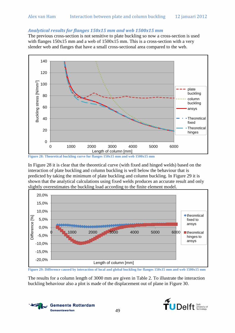
Alex van Ham Interaction between plate and column buckling 12 januari 2012
49
Analytical results for flanges 150x15 mm and web 1500x15 mm The previous cross-section is not sensitive to plate buckling so now a cross-section is used
with flanges 150x15 mm and a web of 1500x15 mm. This is a cross-section with a very
slender web and flanges that have a small cross-sectional area compared to the web.
Figure 28: Theoretical buckling curve for flanges 150x15 mm and web 1500x15 mm
In Figure 28 it is clear that the theoretical curve (with fixed and hinged welds) based on the
interaction of plate buckling and column buckling is well below the behaviour that is
predicted by taking the minimum of plate buckling and column buckling. In Figure 29 it is
shown that the analytical calculations using fixed welds produces an accurate result and only
slightly overestimates the buckling load according to the finite element model.
Figure 29: Difference caused by interaction of local and global buckling for flanges 150x15 mm and web 1500x15 mm
The results for a column length of 3000 mm are given in Table 2. To illustrate the interaction
buckling behaviour also a plot is made of the displacement out of plane in Figure 30.
0
20
40
60
80
100
120
140
0 1000 2000 3000 4000 5000 6000
Bucklin
g s
tress [N
/mm
2]
Length of column [mm]
plate buckling
column buckling
ansys
Theoretical fixed
Theoretical hinges
-20,0%
-15,0%
-10,0%
-5,0%
0,0%
5,0%
10,0%
15,0%
20,0%
0 1000 2000 3000 4000 5000 6000
Diffe
rence [%
]
Length of column [mm]
theoretical fixed to ansys
theoretical hinges to ansys
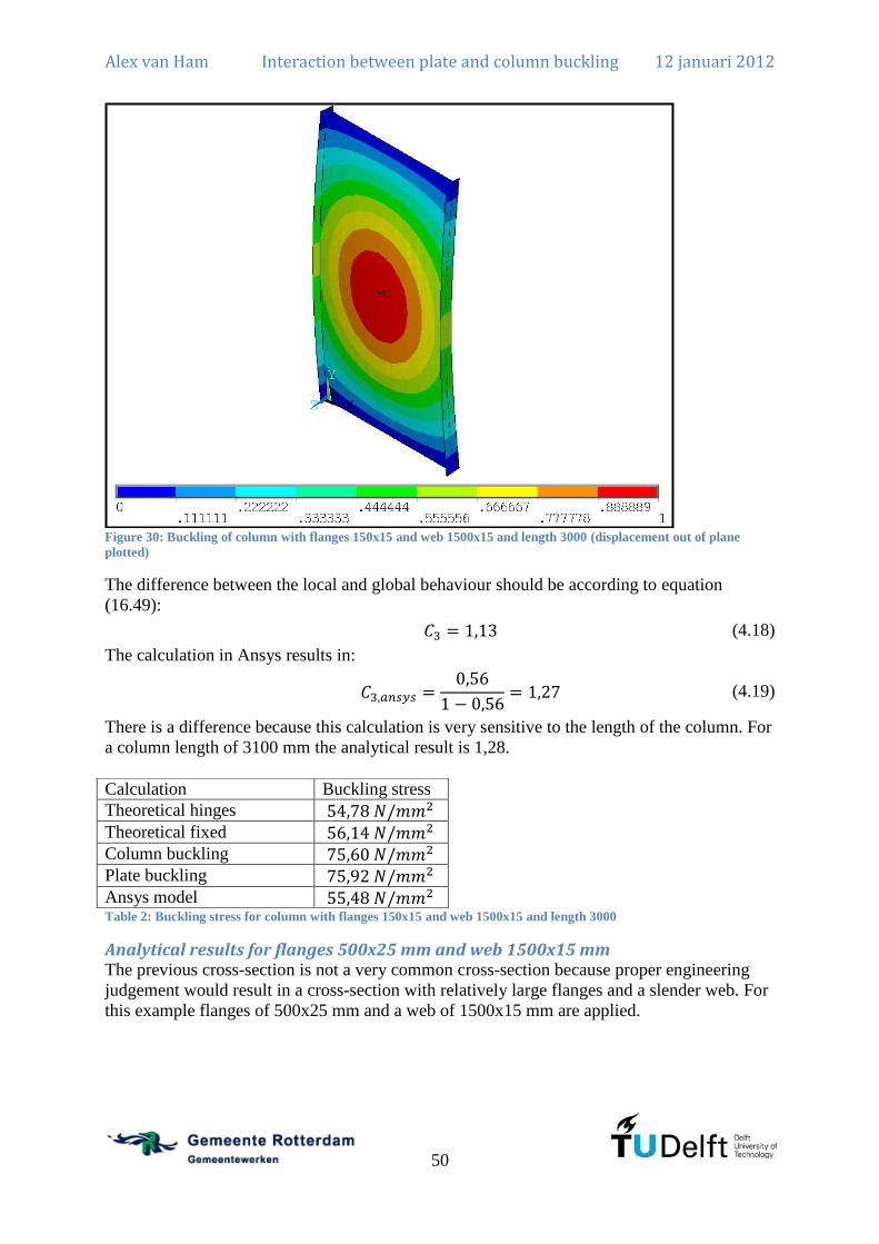
Alex van Ham Interaction between plate and column buckling 12 januari 2012
50
Figure 30: Buckling of column with flanges 150x15 and web 1500x15 and length 3000 (displacement out of plane
plotted)
The difference between the local and global behaviour should be according to equation
(16.49):
(4.18)
The calculation in Ansys results in:
(4.19)
There is a difference because this calculation is very sensitive to the length of the column. For
a column length of 3100 mm the analytical result is 1,28.
Table 2: Buckling stress for column with flanges 150x15 and web 1500x15 and length 3000
Analytical results for flanges 500x25 mm and web 1500x15 mm The previous cross-section is not a very common cross-section because proper engineering
judgement would result in a cross-section with relatively large flanges and a slender web. For
this example flanges of 500x25 mm and a web of 1500x15 mm are applied.
Calculation Buckling stress
Theoretical hinges
Theoretical fixed
Column buckling
Plate buckling
Ansys model

Alex van Ham Interaction between plate and column buckling 12 januari 2012
51
Figure 31: Theoretical buckling curve for flanges 500x25 mm and web 1500x15 mm
Figure 32: Difference caused by interaction of local and global buckling for flanges 500x25 mm and web 1500x15 mm
In Figure 31 the theoretical buckling curve is plotted and the difference between the
theoretical curve and the result in Ansys is given in Figure 32. It is clear that the model using
fixed connections between the flanges and the web is much more accurate but does again
overestimate the buckling load as in the previous cases. For a column length of 17500 mm the
results are given in Table 3.
Calculation Buckling stress
Theoretical hinges
Theoretical fixed
Column buckling
Plate buckling
Ansys model Table 3: Buckling stress for column with flanges 500x25 and web 1500x15 and length 17500
0
20
40
60
80
100
120
140
160
0 5000 10000 15000 20000 25000
Bucklin
g s
tress [N
/mm
2]
Length of column [mm]
plate buckling
column buckling
ansys
Theoretical fixed
Theoretical hinges
-70,00%
-60,00%
-50,00%
-40,00%
-30,00%
-20,00%
-10,00%
0,00%
10,00%
20,00%
30,00%
0 5000 10000 15000 20000 25000
Diffe
rence [%
]
Length of column [mm]
theoretical fixed to ansys
theoretical hinges to ansys

Alex van Ham Interaction between plate and column buckling 12 januari 2012
52
Conclusion
General conclusion The buckling stress calculated using the analytical equations with hinged welds is always
lower than the plate buckling stress and the column buckling stress. This is not true for the
analytical calculations with fixed welds.
In the case of stiff flanges it is clear that the model using hinged welds is almost equal to the
minimum of the plate and column buckling stress. However, as seen in the model using fixed
welds and the model in Ansys, it is clear that the buckling stress is much higher when plate
buckling is governing because the flanges prevent a large rotation at the welds.
The most important conclusion is that there is only interaction between the local and the
global behaviour if they have the same number of half-waves in the length of the column.
( in this thesis) This conclusion can be used later when the imperfections need to be
modelled to predict the real behaviour of an I-column because the NEN-EN1993-1-5 does not
prescribe that these type of imperfections need to be modelled when calculating the restraint
of a class 4 I-column. It is also important to note that the interaction is larger when the cross-
sectional area of the web is large compared to the cross-sectional area of the flanges.
Rotational restraint The buckling curve calculated has an important assumption that the flanges do not give any
rotational restraint to the web. This is realistic for I-columns with a relatively large width of
the web and flanges with a low rotational stiffness. It has been shown that the buckling curve
calculated is a good approximation of the buckling curve according to the model in Ansys in
those cases. However, when stiff flanges are applied the buckling curve is underestimated and
the model in Annex D using fixed welds is a much more accurate result but does overestimate
the theoretical buckling load. The disadvantage is that for the model using fixed welds a
larger matrix has to be solved.
Theoretical model The behaviour calculated now gives a proper inside in the way buckling happens in an I-
column. It is clear that the buckling load is much better approximated using the method
described here but always requires a determinant of a matrix to be solved or an approximation
formula should be developed. It is questionable if this is necessary especially as it is a
combination of two buckling phenomena which have a completely different post-buckling
behaviour. Therefore the understanding of the interaction of plate and column buckling is
more important than the actual result of the calculation.

Alex van Ham Interaction between plate and column buckling 12 januari 2012
53
Chapter 5: I-column according to the NEN-EN1993-1-1 and NEN6771 NEN-EN1993 gives requirements on the design of steel structures. The requirements are
concerned with the static strength and the stability of steel structures. The static strength of
steel structures is not part of this thesis. Therefore the section on the stability of steel
structures is used here and applied upon the I-column in compression. In NEN-EN1993-1-1
the section 6.3 describes the calculation for stability of steel members. For the calculation of
class 4 cross-sections a reference is made to NEN-EN1993-1-5 to calculate the effective
cross-section.
Stability of a welded I-column under uniform compression
According to NEN-EN1993-1-1 A welded I-column under uniform compression has to be checked using equation 6.46 from
NEN-EN1993-1-1:
(5.1)
In this case only the resistance is interesting and this is described by equation 6.48 from NEN-
EN1993-1-1 for class 4 cross-sections:
(5.2)
It is assumed that only the web has to be reduced for plate buckling. Therefore the minimum
requirement of the flanges is that:
(5.3)
For the calculation of NEN-EN1993-1-5 has to be considered. This calculation has been
shown before and is repeated here. The critical buckling stress for the web is:
(5.4)
Therefore the relative slenderness for plate buckling of the web is:
(5.5)
The reduction factor for plate buckling of the web is:
(5.6)
Therefore the effective area of the I-column is the following:
(5.7)
According to equation 6.49 from NEN-EN1993-1-1 the relative slenderness of the I-column
is:
(5.8)
The critical buckling load is calculated using the gross cross-section and is given by:

Alex van Ham Interaction between plate and column buckling 12 januari 2012
54
(5.9)
Using the relative slenderness the reduction factor can be calculated using the following
equation:
(5.10)
In which is:
(5.11)
The factor depends on the type of cross-section that is applied. The correct buckling curve
can be obtained from Figure 33.

Alex van Ham Interaction between plate and column buckling 12 januari 2012
55
Figure 33: Choice of buckling curve according to NEN-EN1993-1-1 table 6.2 (in Dutch)
When the buckling curve is known the correct value for can be obtained from Figure 34.
Figure 34: Factor dependent on the buckling curve chosen according to NEN-EN1993-1-1 table 6.1 (in Dutch)
Now the resistance can be calculated. This resulting resistance can be compared to the
calculations using FEM methods later on.
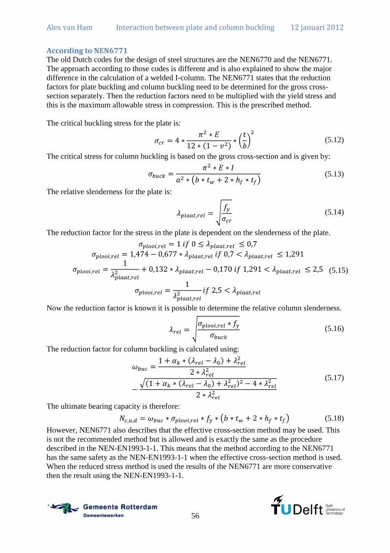
Alex van Ham Interaction between plate and column buckling 12 januari 2012
56
According to NEN6771 The old Dutch codes for the design of steel structures are the NEN6770 and the NEN6771.
The approach according to those codes is different and is also explained to show the major
difference in the calculation of a welded I-column. The NEN6771 states that the reduction
factors for plate buckling and column buckling need to be determined for the gross cross-
section separately. Then the reduction factors need to be multiplied with the yield stress and
this is the maximum allowable stress in compression. This is the prescribed method.
The critical buckling stress for the plate is:
(5.12)
The critical stress for column buckling is based on the gross cross-section and is given by:
(5.13)
The relative slenderness for the plate is:
(5.14)
The reduction factor for the stress in the plate is dependent on the slenderness of the plate.
(5.15)
Now the reduction factor is known it is possible to determine the relative column slenderness.
(5.16)
The reduction factor for column buckling is calculated using:
(5.17)
The ultimate bearing capacity is therefore:
(5.18)
However, NEN6771 also describes that the effective cross-section method may be used. This
is not the recommended method but is allowed and is exactly the same as the procedure
described in the NEN-EN1993-1-1. This means that the method according to the NEN6771
has the same safety as the NEN-EN1993-1-1 when the effective cross-section method is used.
When the reduced stress method is used the results of the NEN6771 are more conservative
then the result using the NEN-EN1993-1-1.

Alex van Ham Interaction between plate and column buckling 12 januari 2012
57
Figure 35: Design load for column with flanges 500x25 and web 1500x15 according to NEN and Eurocode
The difference between the NEN-EN1993-1-1 and the NEN6771 is illustrated in Figure 35 for
a certain cross-section. The major difference for the NEN6771 is immediately clear because
for smaller lengths the capacity is almost twice as high for the NEN-EN1993-1-1. This is
indeed the expected behaviour because the reduced stress method prescribes that the flanges
need to be reduced with the same factor as the web. The effective cross-section method
prescribes that the flanges can be exploited up to the yield strength for short columns. For
much longer lengths the column buckling factor is governing and the difference is very small
because the procedures for column buckling are identical in the codes. For cross-sections with
an almost fully effective web, the reduction is very small, therefore, the difference will be
small. If the slenderness of the web increases, the reduction factor increases and therefore the
difference between the NEN-EN1993-1-1 and the NEN6771 increases. More extensive
research has been done on the major differences between the NEN-EN1993-1-5 and the
NEN6771 considering plate buckling. (Burg, 2011)
0,0E+00
1,0E+06
2,0E+06
3,0E+06
4,0E+06
5,0E+06
6,0E+06
7,0E+06
8,0E+06
9,0E+06
0 5000 10000 15000 20000 25000 30000
Desig
n load [
N]
Column length [mm]
Design load NEN-EN1993-1-1
Design load NEN6771


Alex van Ham Interaction between plate and column buckling 12 januari 2012
59
Chapter 6: I-column in FEM Now the bearing capacity of the I-column is known according to the NEN-EN1993-1-5 it is
necessary to determine the bearing capacity according to finite element calculations. Finite
element methods are capable of calculating constructions including the effects of geometrical
non-linear behaviour (large displacements and rotations) and physical non-linear behaviour
(plasticity). This is not in the analytical calculation of Chapter 4.
A real structure is never perfectly straight and has to be welded and therefore has geometrical
imperfections and residual stresses. Geometrical imperfections can easily be included in a
finite element model but residual stresses are much more difficult to include. Therefore often
the combination of geometrical imperfections and residual stresses is included using a single
geometric imperfection.
NEN-EN1993-1-5 gives a recommendation for the imperfections that need to be used. This is
a global buckling behaviour of the column combined with a local buckling behaviour of the
web. However, as shown in Chapter 4 this is not the lowest buckling load and therefore the I-
column will also be calculated according to the imperfections of Chapter 4. The main goal is
to find out if the buckling curves according to the NEN-EN1993-1-1 represent the same
behaviour as the finite element calculations with imperfections according to the NEN-
EN1993-1-1. Then the question is whether the use of the imperfections according to the NEN-
EN1993-1-5 results in the same bearing load as the imperfections according to Chapter 4.
a
nxx nxxx
y
v
u
z
y
w1
tw
b
hf
tf
w2
Figure 36: Welded I-column in FEM
The model is a simply supported column as given in Figure 36. This is the same as Figure 22
where the situation is described except that in FEM it is possible to rotate the flanges in a 3D-
model.

Alex van Ham Interaction between plate and column buckling 12 januari 2012
60
Displacement control vs Force control An important difference is between the use of displacement control and force control. First of
all this is an essential part as a form of snap through behaviour may not be detected if force
control is applied. However, there is a difference in modelling the real behaviour.
Displacement controlled means that the displacement is prescribed at one end of the column
for the entire cross-section. Therefore if a part of the cross-section, most likely the web, has a
smaller stiffness the other parts of the cross-section, most likely the flanges, will take more
loading. This means that a distribution of loading has to take place according to the largest
stiffness out of plane of the elements. This distribution is only possible if a thick end plate is
used. If there is no thick end plate, forces may not be distributed according to stiffness. In this
case a more realistic approach would be a force controlled behaviour where each element of
the cross-section is loaded and forces are only transferred through the welds between the
flanges and the web. This is a completely different behaviour and should be investigated
separately.
It is also clear that if a relative high buckling factor is applicable for the column the
connection needs to be able to carry a relative high percentage of the plastic capacity.
Therefore the connection also needs to introduce load onto the flanges otherwise yielding of
the web is governing for the column. This is in general through a stiff connection.
In general it can be stated that the forces are introduced through a thick end plate and
distributed according to the load bearing capacity of the individual elements. Therefore in this
thesis a displacement control is applied. However, one should be wary when using the
effective cross-section method that this is an essential assumption in the method.
Model description For the calculation of the welded I-column in FEM the chosen program is Ansys. This
program has been used in previous research (Burg, 2011) and is used as a starting point for
this research. The model is described in previous research and only the changes that are
applied are discussed here. The general concept of the model is explained in Figure 37 and the
corresponding command grouping is given.
Figure 37: Flow chart of the process in FEM including the Ansys group commands
First of all the model needed is a hinged column and not a fixed column at both ends. In a 3D-
model this is a complex model because a line support at the flanges will create a fixed end. To
overcome this problem a very stiff beam is applied at the flanges and is supported at the web
with a support. Therefore the flanges can rotate but act as a support through the beam. This is
shown in Figure 38. This model does prevent local forms of instability at the point of load
introduction. That is not a subject in this thesis and is therefore correct.
Model creation
/prep7
Static analysis
/solve
Linear buckling analysis
/solve
Evaluate buckling analysis
/post1 and /post26
Update geometry with chosen buckling
shape
/prep7
Static nonlinear analysis
/solve
Evaluate nonlinear analysis
/post1 and /post26

Alex van Ham Interaction between plate and column buckling 12 januari 2012
61
uz
ux
Figure 38: Hinged column support in 3D model. Displacement described at web and thick line is the very stiff beam.
Second is the use of do commands to calculate many cases and save the data to a file which
can be used in Excel. It is possible to insert the data for a certain cross-section and the column
is calculated for a number of lengths so the buckling curve is known by issuing two
commands.
The verification of the model is presented in Annex F.
Single geometrical imperfections The third important change is in the way the imperfections are modelled. The imperfections
need to be modelled according to the NEN-EN1993-1-5 and according to the real buckling
behaviour described in Chapter 4.
The single geometric imperfection is a method to replace the real geometrical imperfections
and the residual stresses. For a welded I-column the correct buckling curve depends on the
thickness of the flanges. If the flanges are thinner than 40 mm the correct buckling curve is c
and for flanges thicker than 40 mm the buckling curve is d. Thicker flanges have higher
residual stresses because of the larger temperature differences. Thin flanges have a more
uniform temperature in the cross-section. Therefore the residual stresses are lower. However,
for thicker flanges the single geometric imperfection replacing the residual stresses is not
higher. Therefore in the FEM-results the effect of higher residual stresses in thicker flanges is
not included. Because it is not included, the application of buckling curve d is not valid for
the comparison of the FEM-results to the NEN-EN1993-1-1. Therefore all calculations are
done using buckling curve c for axial compression of welded I-columns.
Eurocode imperfections First the web is modelled with supports along its edges as described for a perfect plate. Then
the lowest eigenvalue is calculated (Figure 39) and applied upon the plate with magnitude:
(6.1)

Alex van Ham Interaction between plate and column buckling 12 januari 2012
62
Figure 39: The local imperfection of the web according to the Eurocode
The factor is used because only the governing mechanism should be applied at full scale
and all other instability configurations may be scaled to 70% of the given limit. The major
displacement is the global buckling behaviour and plate buckling is the secondary buckling
mode.
Then the flanges are added to the construction and the entire model is forced to displace only
in z-direction. The buckling load is the global buckling behaviour (Figure 40) and is applied
upon the entire column with magnitude equal to:
(6.2)
Figure 40: The global imperfection of the entire section according to the Eurocode

Alex van Ham Interaction between plate and column buckling 12 januari 2012
63
The combination of the two displacements are applied to the construction and then the non-
linear calculation can be done.
Imperfections according to lowest buckling load The imperfections according to the buckling load are more difficult. The buckling load with
should be applied because otherwise global buckling is not initiated. The
behaviour with is the displacement of the I-column out of plane in a half-sine and an
additional displacement of the web in a half-sine wave is added to the displacement. The
behaviour with is not always the lowest buckling load as shown in Chapter 4 and
should therefore be found. This is done by calculating many buckling loads and calculating
the total displacement in z-direction of all nodes for each buckling load. The buckling load
with the largest total displacement in z-direction is the buckling load with . (Figure 41)
This buckling load is applied.
Figure 41: Imperfection of the entire section according to Chapter 4
Scaling this buckling load has to be done depending on the displacement of the web and the
displacement of the flange. The displacement has to be scaled according to the maximum
allowable displacement of the flange and the maximum allowable displacement of the web as
they are given in the NEN-EN1993-1-5.
If the local displacement is large compared to the global displacement the scaling factor will
depend on the local behaviour. This is given by:
(6.3)
If the global displacement is large compared to the local behaviour the scaling factor will
depend on the global behaviour.
(6.4)
If the displacement is not specified by the above equations the scaling factor will depend on
both and therefore the following two equations are provided to calculate the scaling factor if
there is no governing displacement.

Alex van Ham Interaction between plate and column buckling 12 januari 2012
64
(6.5)
(6.6)
The imperfection is therefore known and a non-linear calculation can be done.
Imperfections according to Eurocode using m=1 Imperfections according to the buckling load give a problem that either the local or the global
imperfection is scaled down below the level of 70% of the maximum which is prescribed for a
secondary imperfection. Therefore another imperfection model is added which works the
same as the previously described model which generates imperfections according to the NEN-
EN1993-1-5. However, it has been shown in Chapter 4 that there is only interaction in the
theoretical buckling load when the number of half sine waves in the flanges is equal to the
number of half sine waves in the web. This is chosen at here.
Figure 42: The local imperfection of the web according to the Eurocode using
For this model the buckling modes of the web are calculated and for each mode the total
deflection out of plane is calculated. The mode with the largest total imperfection out of plane
is applied at the web. (Figure 42) Then the flanges are added to the model and the buckling
modes are again calculated. For the buckling modes the total deflection out of plane is
calculated and the mode with the largest out of plane deflection is added to the entire column.
(Figure 40)
Results Many cases using different dimensions for the flange and web have been calculated and the
results are presented in Annex F. Only for two configurations the results are presented and
discussed.

Alex van Ham Interaction between plate and column buckling 12 januari 2012
65
Class 4 profile with large flanges (flanges 500x25 mm and web 1500x15 mm) This profile has been calculated before for the theoretical buckling load and it proved that the
interaction between column buckling and plate buckling was very small and reduced the
buckling load by only 1%. Now the geometrical imperfections and residual stresses can be
taken into account using a single geometric imperfection. For a certain configuration several
plots can be made such as Figure 43 which shows the axial compressive load as a function of
the displacement that is applied at the top of the column.
Figure 43: Load-in plane displacement graph for flanges 500x25 and web 1500x15 and length 10000
Also plots such as Figure 44 can be made which shows the axial compressive load as a
function of the out of plane displacement of the web. This plot does not start in the origin
because of the single geometric imperfection that is applied before loading.
Figure 44: Load-out of plane displacement graph for flanges 500x25 and web 1500x15 and length 10000
These are just to illustrate the results for one situation and can be made for all situations.
These results give the maximum axial compressive load and the real buckling curve can be
determined. This is done by running the model a number of times in Ansys with a different
column length. This will result in plots as given in Figure 45.
0,0E+00
5,0E+05
1,0E+06
1,5E+06
2,0E+06
2,5E+06
3,0E+06
3,5E+06
4,0E+06
4,5E+06
5,0E+06
0,0 5,0 10,0 15,0 20,0 25,0
Axia
l com
pre
ssio
n [N
]
Vertical displacement applied [mm]
0,0E+00
5,0E+05
1,0E+06
1,5E+06
2,0E+06
2,5E+06
3,0E+06
3,5E+06
4,0E+06
4,5E+06
5,0E+06
0,0 50,0 100,0 150,0 200,0 250,0 300,0 350,0
Axia
l com
pre
ssio
n [N
]
Displacement out of plane of web [mm]
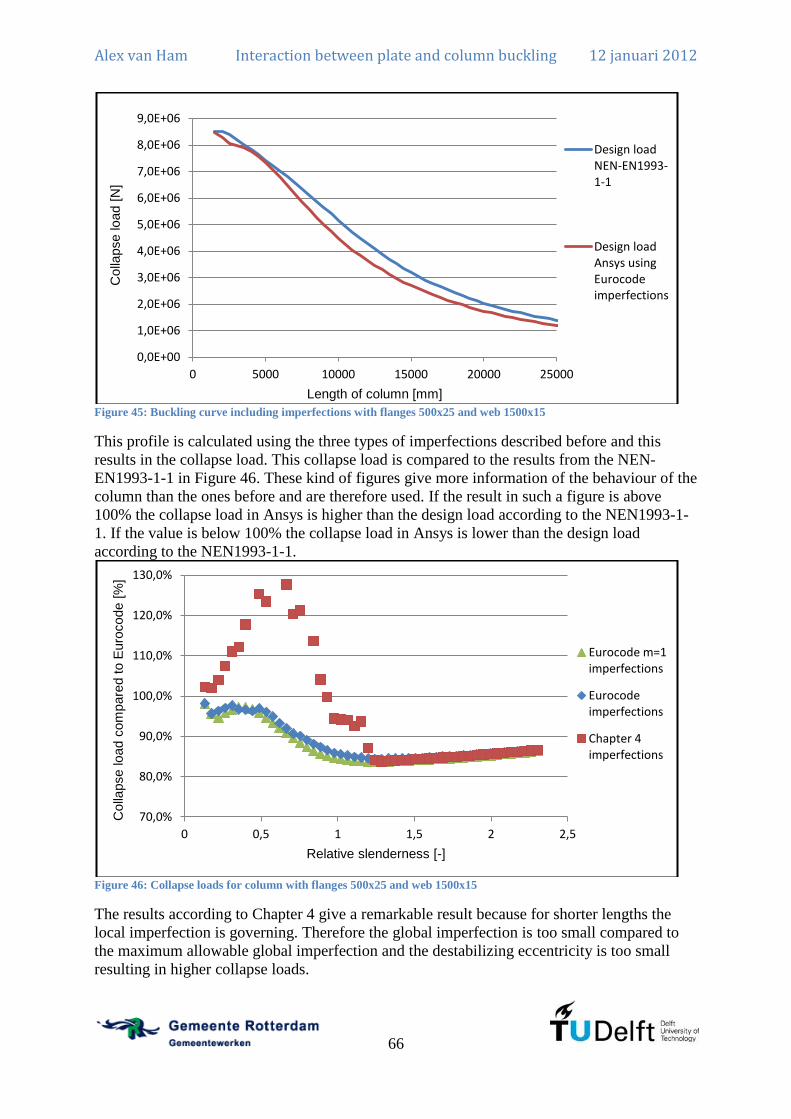
Alex van Ham Interaction between plate and column buckling 12 januari 2012
66
Figure 45: Buckling curve including imperfections with flanges 500x25 and web 1500x15
This profile is calculated using the three types of imperfections described before and this
results in the collapse load. This collapse load is compared to the results from the NEN-
EN1993-1-1 in Figure 46. These kind of figures give more information of the behaviour of the
column than the ones before and are therefore used. If the result in such a figure is above
100% the collapse load in Ansys is higher than the design load according to the NEN1993-1-
1. If the value is below 100% the collapse load in Ansys is lower than the design load
according to the NEN1993-1-1.
Figure 46: Collapse loads for column with flanges 500x25 and web 1500x15
The results according to Chapter 4 give a remarkable result because for shorter lengths the
local imperfection is governing. Therefore the global imperfection is too small compared to
the maximum allowable global imperfection and the destabilizing eccentricity is too small
resulting in higher collapse loads.
0,0E+00
1,0E+06
2,0E+06
3,0E+06
4,0E+06
5,0E+06
6,0E+06
7,0E+06
8,0E+06
9,0E+06
0 5000 10000 15000 20000 25000
Colla
pse load [
N]
Length of column [mm]
Design load NEN-EN1993-1-1
Design load Ansys using Eurocode imperfections
70,0%
80,0%
90,0%
100,0%
110,0%
120,0%
130,0%
0 0,5 1 1,5 2 2,5
Colla
pse load c
om
pare
d to E
uro
code [
%]
Relative slenderness [-]
Eurocode m=1 imperfections
Eurocode imperfections
Chapter 4 imperfections

Alex van Ham Interaction between plate and column buckling 12 januari 2012
67
The difference between the results from the NEN-EN1993-1-1 verification and the results
with a single half sine wave (NEN-EN1993-1-5 with ) are small and the difference is at
most 2%. In general the collapse loads using are smaller but the difference is small.
The difference is plotted in Figure 47.
Figure 47: Percentual difference between Eurocode imperfections and Eurocode imperfections
The general trend shows a correct collapse load according to the verification regulations for a
relative slenderness up to 0,6 but a higher relative slenderness results in an overestimate of the
collapse load of up to 17%.
Class 4 profile with small flanges (flanges 150x15 mm and web 1500x15 mm) The profile with small flanges that has been calculated in Chapter 4 is also calculated in
Ansys using finite elements. The interaction between plate and column buckling resulted in a
24% lower theoretical buckling load. The collapse load as it is calculated in Ansys compared
to the results according to the NEN-EN1993-1-1 verification is presented in Figure 48.
Figure 48: Collapse loads for column with flanges 150x15 and web 1500x15
-2,50%
-2,00%
-1,50%
-1,00%
-0,50%
0,00%
0,50%
1,00%
0 5000 10000 15000 20000 25000 30000
Diffe
rence b
etw
een E
uro
cdoe m
=1
imperf
ections a
nd E
uro
code
imperf
ections [%
]
Column length [mm]
60,0%
65,0%
70,0%
75,0%
80,0%
85,0%
90,0%
95,0%
0 0,5 1 1,5 2 2,5 3 3,5
Colla
pse load c
om
pare
d to E
uro
code [
%]
Relative slenderness [-]
Eurocode m=1 imperfections
Eurocode imperfections
Chapter 4 imperfections

Alex van Ham Interaction between plate and column buckling 12 januari 2012
68
The results using the imperfections from Chapter 4 give an overestimate for a low relative
slenderness as explained before. For a higher relative slenderness the result is about equal to
the results using imperfections according to the NEN-EN1993-1-1 verification. So the result
using the imperfections from Chapter 4 are from here on omitted.
The lowest relative slenderness calculated is a result from a length of 1500 mm so a square
column is applied. This is not in accordance with the Bernoulli theory that flat cross-sections
remain flat and therefore the results for very short columns should be ignored up to a length
of approximately 4500 mm. The collapse load using the imperfections in the NEN-EN1993-1-
5 give a 33% difference compared to the NEN-EN1993-1-1 verification.
The imperfections using gives a significant difference compared to the imperfections
according to the NEN-EN1993-1-5. For a very small length this is equal because the lowest
plate buckling mode is also a single half sine wave. However, when that length is exceeded
the difference is 5,5% in the collapse load which does indicate that there is a significant
difference when a single half sine wave is chosen as the imperfection. This difference is
presented in Figure 49.
Figure 49: Percentual difference between Eurocode imperfections and Eurocode imperfections
Sensitivity analysis The model is applied in a number of cases but the sensitivity with respect to a number of
variables needs to be investigated. The buckling curves are applicable for many situations and
before conclusions are drawn on the basis of the previous results it is necessary to investigate
the sensitivity of the variables. The important variables that will be investigated are the yield
stress and the size of the imperfections.
Yield stress All previous results have been obtained using a yield stress of which is the most
common steel grade applied. However, in recent years higher strength steel is applied more
frequently and the sensitivity to the yield stress should be investigated. For the column with
flanges 500x25 mm and web 1500x15 mm, using the imperfections in the NEN-EN1993-1-5,
the difference between the Ansys collapse load and the NEN-EN1993-1-1 verification is
plotted in Figure 50 for three different steel grades. ( , and )
-6,0%
-5,0%
-4,0%
-3,0%
-2,0%
-1,0%
0,0%
0 1000 2000 3000 4000 5000 6000 7000 8000 9000
Diffe
rence b
etw
een E
uro
cdoe m
=1
imperf
ections a
nd E
uro
code
imperf
ections [%
]
Column length [mm]

Alex van Ham Interaction between plate and column buckling 12 januari 2012
69
It is clear from Figure 50 that the yield stress does influence the behaviour and the difference
between the model and the NEN-EN1993-1-1 verification is smaller when the yield stress is
higher. This is consistent with the NEN-EN1993-1-1 because for many types of profiles S460
has a higher buckling curve so the reduction is smaller. This is given in table 6.2 of NEN-
EN1993-1-1. However, this is not true for welded I-columns so here the same buckling curve
is applied for all calculations.
Figure 50: Sensitivity of non-linear analysis to yield stress
Imperfections The imperfections are added to the structure according to the limits given in the NEN-
EN1993-1-5 for calculations using finite elements. These single geometric imperfections
represent the real geometrical imperfections and the residual stresses. The question is whether
a slight increase or decrease of the imperfections results in a considerable change of load
bearing capacity. For the column with flanges 500x25 mm and web 1500x15 mm the
difference between the Ansys collapse load and the NEN-EN1993-1-1 verification is plotted
in Figure 51 for three different imperfections. (1/150, 1/200 and 1/250) Both the local
imperfection of the web and the global imperfection of the entire cross-section is changed. All
verifications are done using buckling curve c as is prescribed for welded I cross-sections.
80,0%
85,0%
90,0%
95,0%
100,0%
105,0%
0 0,5 1 1,5 2 2,5 3 3,5
Colla
pse load c
om
pare
d to E
uro
code [
%]
Relative slenderness [-]
S235
S355
S460
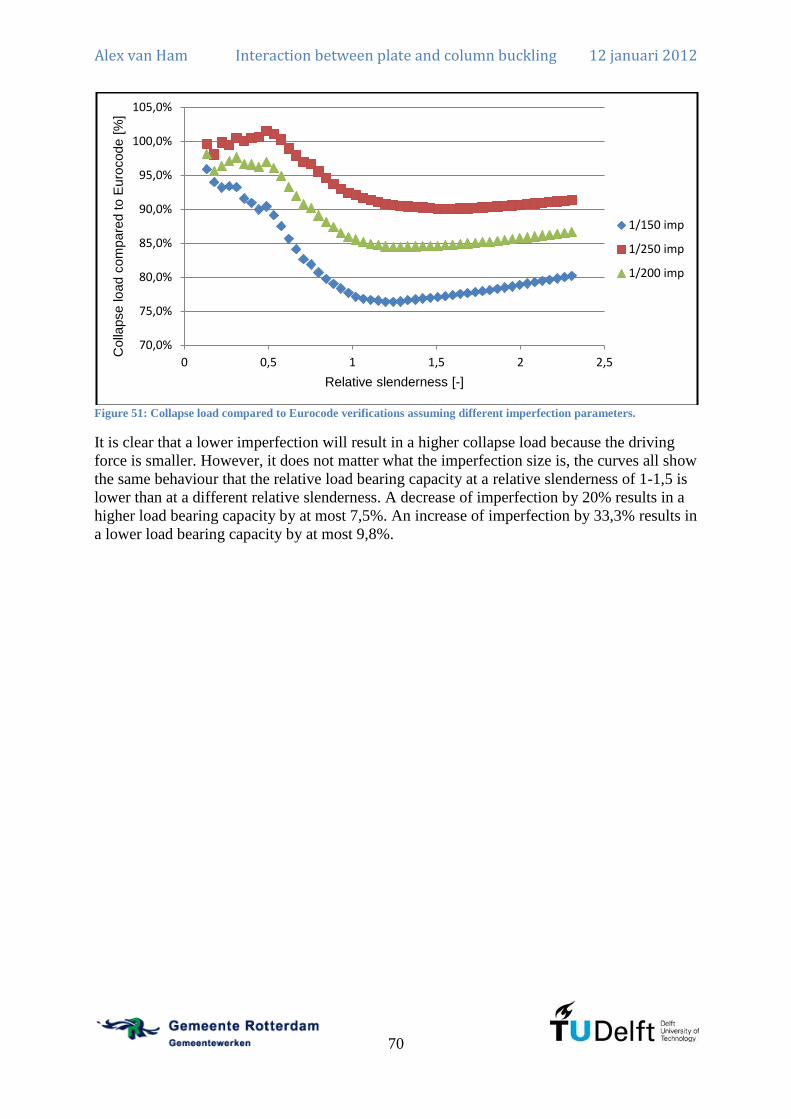
Alex van Ham Interaction between plate and column buckling 12 januari 2012
70
Figure 51: Collapse load compared to Eurocode verifications assuming different imperfection parameters.
It is clear that a lower imperfection will result in a higher collapse load because the driving
force is smaller. However, it does not matter what the imperfection size is, the curves all show
the same behaviour that the relative load bearing capacity at a relative slenderness of 1-1,5 is
lower than at a different relative slenderness. A decrease of imperfection by 20% results in a
higher load bearing capacity by at most 7,5%. An increase of imperfection by 33,3% results in
a lower load bearing capacity by at most 9,8%.
70,0%
75,0%
80,0%
85,0%
90,0%
95,0%
100,0%
105,0%
0 0,5 1 1,5 2 2,5
Colla
pse load c
om
pare
d to E
uro
code [
%]
Relative slenderness [-]
1/150 imp
1/250 imp
1/200 imp
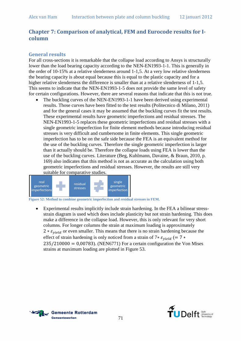
Alex van Ham Interaction between plate and column buckling 12 januari 2012
71
Chapter 7: Comparison of analytical, FEM and Eurocode results for I-column
General results For all cross-sections it is remarkable that the collapse load according to Ansys is structurally
lower than the load bearing capacity according to the NEN-EN1993-1-1. This is generally in
the order of 10-15% at a relative slenderness around 1-1,5. At a very low relative slenderness
the bearing capacity is about equal because this is equal to the plastic capacity and for a
higher relative slenderness the difference is smaller than at a relative slenderness of 1-1,5.
This seems to indicate that the NEN-EN1993-1-5 does not provide the same level of safety
for certain configurations. However, there are several reasons that indicate that this is not true.
The buckling curves of the NEN-EN1993-1-1 have been derived using experimental
results. Those curves have been fitted to the test results (Politecnico di Milano, 2011)
and for the general cases it may be assumed that the buckling curves fit the test results.
These experimental results have geometric imperfections and residual stresses. The
NEN-EN1993-1-5 replaces these geometric imperfections and residual stresses with a
single geometric imperfection for finite element methods because introducing residual
stresses is very difficult and cumbersome in finite elements. This single geometric
imperfection has to be on the safe side because the FEA is an equivalent method for
the use of the buckling curves. Therefore the single geometric imperfection is larger
than it actually should be. Therefore the collapse loads using FEA is lower than the
use of the buckling curves. Literature (Beg, Kuhlmann, Davaine, & Braun, 2010, p.
169) also indicates that this method is not as accurate as the calculation using both
geometric imperfections and residual stresses. However, the results are still very
suitable for comparative studies.
Figure 52: Method to combine geometric imperfection and residual stresses in FEM.
Experimental results implicitly include strain hardening. In the FEA a bilinear stress-
strain diagram is used which does include plasticity but not strain hardening. This does
make a difference in the collapse load. However, this is only relevant for very short
columns. For longer columns the strain at maximum loading is approximately
or even smaller. This means that there is no strain hardening because the
effect of strain hardening is only noticed from a strain of 7 (
). (NEN6771) For a certain configuration the Von Mises
strains at maximum loading are plotted in Figure 53.
real geometric
imperfections
residual stresses
single geometric
imperfection

Alex van Ham Interaction between plate and column buckling 12 januari 2012
72
Figure 53: Von Mises strains at maximum loading of I-column with flanges 500x50 and web 1500x10 and length 10000
For these reasons a slight difference of 10-15% between the collapse load in FEA and NEN-
EN1993-1-1 verification is accepted as reasonable. All buckling curves show the same
behaviour with the largest difference at a relative slenderness between 1,0 and 1,5.
Influence ratio web to flange However, for some cross-sections the largest difference is around 30-35% and this cannot be
explained as this is only true for some cross-sections and it is not a general trend. It is noticed
that the difference is larger if the web has a larger area compared to the flanges. This does
make sense because the web has nearly no resistance against global buckling. However, if the
web is larger, the flanges need to be able to carry a larger driving force of the web. For a
cross-section with flanges 500x50 mm and a web with a width of 1500 mm and a variable
thickness the difference between the collapse load in Ansys and the NEN-EN1993-1-1
verification are plotted in Figure 54. It is clear that the difference between the collapse in
Ansys and the NEN-EN1993-1-1 verification increases with an increasing thickness of the
web. This difference is not only present for class 4 cross-sections but does also arise for class
3 and higher classifications.

Alex van Ham Interaction between plate and column buckling 12 januari 2012
73
Figure 54: Collapse load compared to the Eurocode for flanges 500x50 mm and web with a width of 1500 mm
The general trend is that the largest difference is around a relative slenderness of 1 to 1,5. For
each cross-section the largest difference is plotted as a function of the web thickness in Figure
55.
Figure 55: Largest difference collapse load compared to Eurocode for flanges 500x50 mm and web with a width of
1500 mm
More cases have been calculated using different configurations and therefore the difference in
collapse load is plotted as a function of the ratio of the area of the web to the area of the
flange in Figure 56. The dimensionless scaling parameter is named:
75,0%
80,0%
85,0%
90,0%
95,0%
100,0%
105,0%
0 0,5 1 1,5 2 2,5
Colla
pse load c
om
pare
d to E
uro
code [
%]
Relative slenderness [-]
t=5
t=10
t=15
t=20
t=25
t=30
t=35
t=40
t=45
t=50
y = -0,0031x + 0,8951 R² = 0,9776
70,0%
72,0%
74,0%
76,0%
78,0%
80,0%
82,0%
84,0%
86,0%
88,0%
90,0%
0 10 20 30 40 50 60
Colla
pse load c
om
pare
d to E
uro
code [
%]
Web thickness [mm]

Alex van Ham Interaction between plate and column buckling 12 januari 2012
74
(7.1)
Figure 56: Collapse load compared to Eurocode for several cases
The collapse load therefore is plotted as a function of parameter on a logarithmic scale in
Figure 57.
Figure 57: Collapse load compared to Eurocode as a function of
This gives reason to narrow the margins for the applicability of the buckling load according to
the NEN-EN1993-1-1. If the parameter is the difference between the Ansys and the
y = -0,0233x + 0,851 R² = 0,8009
60,0%
65,0%
70,0%
75,0%
80,0%
85,0%
90,0%
0 2 4 6 8 10 12
Colla
pse load c
om
pare
d t
o E
uro
code [
%]
ω [-]
y = -0,061ln(x) + 0,8237 R² = 0,857
60,0%
65,0%
70,0%
75,0%
80,0%
85,0%
90,0%
0,1 1 10
Colla
pse load c
om
pare
d to E
uro
code [
%]
ω [-]
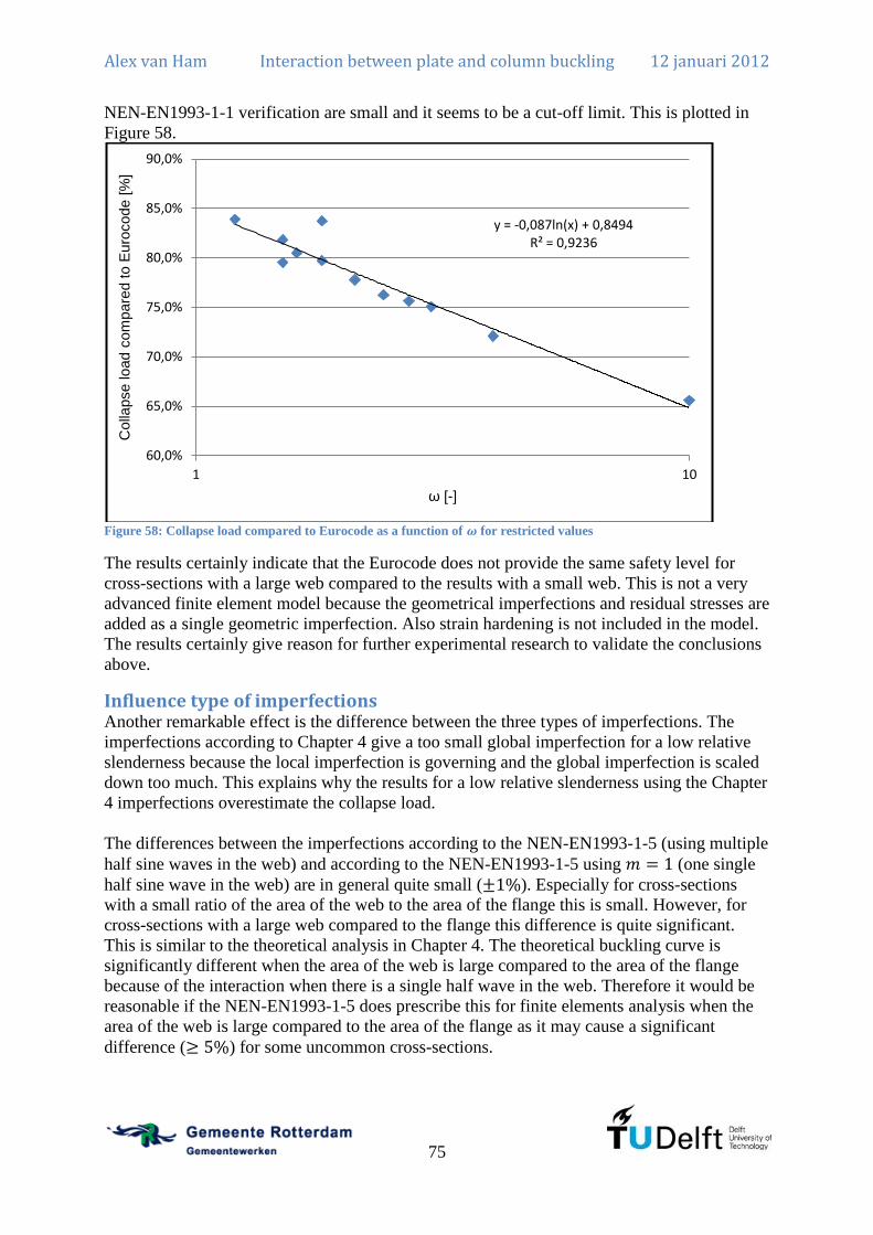
Alex van Ham Interaction between plate and column buckling 12 januari 2012
75
NEN-EN1993-1-1 verification are small and it seems to be a cut-off limit. This is plotted in
Figure 58.
Figure 58: Collapse load compared to Eurocode as a function of for restricted values
The results certainly indicate that the Eurocode does not provide the same safety level for
cross-sections with a large web compared to the results with a small web. This is not a very
advanced finite element model because the geometrical imperfections and residual stresses are
added as a single geometric imperfection. Also strain hardening is not included in the model.
The results certainly give reason for further experimental research to validate the conclusions
above.
Influence type of imperfections Another remarkable effect is the difference between the three types of imperfections. The
imperfections according to Chapter 4 give a too small global imperfection for a low relative
slenderness because the local imperfection is governing and the global imperfection is scaled
down too much. This explains why the results for a low relative slenderness using the Chapter
4 imperfections overestimate the collapse load.
The differences between the imperfections according to the NEN-EN1993-1-5 (using multiple
half sine waves in the web) and according to the NEN-EN1993-1-5 using (one single
half sine wave in the web) are in general quite small ( ). Especially for cross-sections
with a small ratio of the area of the web to the area of the flange this is small. However, for
cross-sections with a large web compared to the flange this difference is quite significant.
This is similar to the theoretical analysis in Chapter 4. The theoretical buckling curve is
significantly different when the area of the web is large compared to the area of the flange
because of the interaction when there is a single half wave in the web. Therefore it would be
reasonable if the NEN-EN1993-1-5 does prescribe this for finite elements analysis when the
area of the web is large compared to the area of the flange as it may cause a significant
difference ( ) for some uncommon cross-sections.
y = -0,087ln(x) + 0,8494 R² = 0,9236
60,0%
65,0%
70,0%
75,0%
80,0%
85,0%
90,0%
1 10
Colla
pse load c
om
pare
d to E
uro
code [
%]
ω [-]


Alex van Ham Interaction between plate and column buckling 12 januari 2012
77
Chapter 8: Probabilistic design on an economic and an uneconomic I-column
Probabilistic design in Ansys The previous analyses have been done using deterministic values as input for the Ansys
model. The deterministic values used are the average values for the dimensions and the
characteristic value for the yield strength. However, the variables in this analysis are in
general probabilistic design variables. The probabilistic design analysis is described in Figure
59. The batch file that describes the analysis for a single set of variables is the same as the
batch file for the deterministic analysis except for the parameters that are defined in the
probabilistic design file.
Figure 59: Flow chart of the process in FEM for probabilistic analysis including the Ansys group commands
Design variables The most difficult part is to estimate the mean values and the variance of the design variables.
There are mechanical design variables, geometrical design variables, imperfection design
variables and a load design variable. All parameters are assumed to be uncorrelated to each
other.
The mechanical design variables can be gained from literature (Stichting CUR, 1997) where
the mean and the variance are given. For the yield strength a lognormal distribution is applied
and for the Young’s modulus a normal distribution is used.
For the geometrical design variables there are regulations that describe the allowable
fabrication tolerances. (NEN-EN1090-2, 2008) The tolerances are given for two types namely
the fundamental and the functional requirements. The first is concerned with the strength and
stability of the construction and the second is concerned with fitting and aesthetics. In general
both are important for a steel construction so the minimum of both requirements is applied.
The lowest and highest allowable tolerances are used as the 95% confidence interval. The
following formula calculates the upper boundary.
(8.1)
The following formula calculates the lower boundary.
(8.2)
The regulations (NEN-EN1090-2, 2008) provide the geometrical tolerances in article 11. The
width of the web is given in D.1.1 and in D.2.1. The most severe requirement results in a
tolerance of
if it is between the boundaries of and :
(8.3)
Import batch file for single analysis
Choose probabilistic design values
Determine mean values
Determine variance
Run model several times
Evaluate probabilistic
results

Alex van Ham Interaction between plate and column buckling 12 januari 2012
78
For the width of the flange the requirement is:
(8.4)
The length of the column is given by:
(8.5)
Tolerances of the material are specified in article 5.3.2 which refers to a different regulation
(EN10029, 1991) where class A has to be applied. The tolerances for the thickness are given
in Table 4.
Nominal thickness Lower margin Upper margin
Table 4: Margins on thickness (all dimensions in mm) of a steel plate according to EN10029 Table 1.
The imperfection design variables are the representation of residual stresses and geometrical
imperfections. These are non-measurable parameters because it is a method to replace the real
structural behaviour. Therefore only an estimate can be made of the mean and the variation.
The variation is estimated at 0,15 because residual stresses and geometrical imperfections are
far from constant. The mean is set such that the characteristic value at three times the standard
deviation (probability at three times standard deviation is 0,13%) is
as described in the
NEN-EN1993-1-5. This can be calculated using:
(8.6)
The relevant numbers applied gives:
(8.7)
Therefore the result is:
(8.8)
Since the local imperfection is highly dependent on the welding process the variation of the
local imperfection is estimated at 0,20. This will result in a mean of the local imperfection:
(8.9)
Also the load is a design variable. In general the characteristic load is defined as the load that
will occur once in the lifetime of the structure with an exceedance probability of 5%. This is
without any safety factors. In this case nothing is known about the loading so it is assumed
that the design load (including safety factors) is equal to the capacity according to the NEN-
EN1993-1-1. The load factor is assumed to be around 1,4 as a combination of the dead load
and the live load. The mean of the load is given by: (Stichting CUR, 1997, pp. 5-52, 5-53)

Alex van Ham Interaction between plate and column buckling 12 januari 2012
79
(8.10)
The safety factors for loading are described by: (Stichting CUR, 1997, pp. 5-52, 5-53)
(8.11)
The -factor required is 3,8 for a reference period of 50 years in consequence class 2 (NEN-
EN1990, 2002). The -factor for dominant loading is equal to (NEN-EN1990, 2002).
Therefore the variance of the load is estimated by:
(8.12)
Now the loading and resistance design variables are all known it is possible to apply the
probabilistic design in Ansys. It is possible to include the load and simply calculate the
probability in the following way using a Monte Carlo analysis:
(8.13)
However, the probability of failure should be very small and the number of simulations for a
reliability of 95% and a relative error of 0,1 should be at least: (Stichting CUR, 1997)
(8.14)
For a probability of this will result in at least 4 million simulations. This is not very
efficient because a single calculation in Ansys takes about 1 minute. Therefore only the
resistance is calculated in Ansys and from that the distribution of the resistance is estimated.
Then the combination of loading and resistance can be calculated using an analytical
calculation. The reliability function ( ) indicates whether a structure is safe or not.
The probability of failure is:
(8.15)
When it is assumed that both are normally distributed the reliability function is also normally
distributed. The mean is given by the following relations assuming the load is independent
from the resistance:
(8.16)
The standard deviation is given by:
(8.17)
Then the -factor is calculated using the following relation and this factor should be at least
3,8 to satisfy the safety demands.
(8.18)
From this -value a probability can be calculated and this can be compared to the probability
required. The required probability is related to a -value of 3,8.
(8.19)

Alex van Ham Interaction between plate and column buckling 12 januari 2012
80
Economic I-column An economic I-column with flanges 500x50 mm and web 1500x10 mm and length 15000 mm
is applied for the probabilistic design analysis. The calculation according to Chapter 5 using
the verification regulations of NEN-EN1993-1-5 results in a design strength of:
(8.20)
Therefore the mean load is equal to:
(8.21)
The standard deviation for the load is given by:
(8.22)
The probabilistic design variables are already specified above and for this configuration the
relevant numbers are calculated in Table 5.
Parameter Description Statistical
spread Mean Standard
deviation
Variation
Length of column Normal
Width of web Normal
Thickness of web Normal
Thickness of flange Normal
Width of flange Normal
Young’s modulus Normal
Yield strength Lognormal
Column imperfection Normal
Web imperfection Normal
Table 5: Design variables for economic I-column
Ansys can perform this probabilistic design analysis and produces a plot of the results on a
Gauss plot as shown in Figure 60. This means that a perfectly straight line would fit a normal
distribution. The resistance is assumed to be normally distributed given the approximate
straight line on a Gaussian cumulative distribution plot. The tail of the distribution is not
straight so this is an assumption which is not entirely correct but this may also be due to the
amount of calculations done.

Alex van Ham Interaction between plate and column buckling 12 januari 2012
81
Figure 60: Cumulative distribution of collapse load according to Ansys for economic cross-section
The dependence of the collapse load on the variables is also calculated by Ansys and is given
in Figure 61. The most important variables are the global imperfection, the mechanical
properties and the width and thickness of the flange. The variance of the others apparently
does not influence the collapse load significantly.
Figure 61: Significance of the design variables to the collapse load.
The mean for the resistance is:

Alex van Ham Interaction between plate and column buckling 12 januari 2012
82
(8.23)
The variance for the resistance is:
(8.24)
Now the mean for the reliability function can be calculated.
(8.25)
The standard deviation is given by:
(8.26)
Then the -factor is calculated using the following relation and this factor should be at least
3,8 to satisfy the safety demand required.
(8.27)
Therefore the probability for failure can be calculated:
(8.28)
Uneconomic I-column An uneconomic I-column with flanges 500x50 mm and web 1500x50 mm and length 15000
mm is applied for the probabilistic design analysis. This is the same as the economic I-column
except for the thickness of the web. In this case, not an extremely uneconomic I-column is
used as in the case of the analytical calculation. The calculation according to Chapter 5 using
the verification regulations of NEN-EN1993-1-5 results in a design load of:
(8.29)
Therefore the characteristic load is equal to:
(8.30)
The standard deviation for the load is given by:
(8.31)
The probabilistic design variables are already specified above and for this configuration the
relevant numbers are calculated in Table 6.
Parameter Description Statistical
spread Mean Standard
deviation
Variation
Length of column Normal
Width of web Normal
Thickness of web Normal
Thickness of flange Normal
Width of flange Normal
Young’s modulus Normal
Yield strength Lognormal
Column imperfection Normal
Web imperfection Normal
Table 6: Design variables for uneconomic I-column

Alex van Ham Interaction between plate and column buckling 12 januari 2012
83
Ansys can perform this probabilistic design analysis and produces a plot of the results on a
Gauss plot as shown in Figure 62. This means that a perfectly straight line would fit a normal
distribution. The resistance is assumed to be normally distributed given the approximate
straight line on a Gaussian cumulative distribution plot. The tail of the distribution is not
straight so this is an assumption which is not entirely correct but this may also be due to the
amount of calculations done.
Figure 62: Cumulative distribution of collapse load according to Ansys for uneconomic cross-section
The dependence of the collapse load on the variables is also calculated by Ansys and is given
in Figure 63. The most important variables are the global imperfection, the mechanical
properties and the width and the thickness of the flange. The variance of the others apparently
does not influence the collapse load significantly.
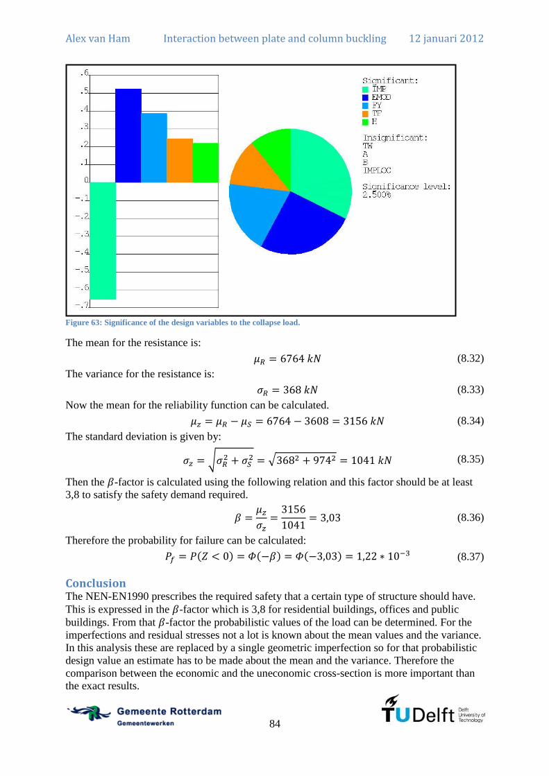
Alex van Ham Interaction between plate and column buckling 12 januari 2012
84
Figure 63: Significance of the design variables to the collapse load.
The mean for the resistance is:
(8.32)
The variance for the resistance is:
(8.33)
Now the mean for the reliability function can be calculated.
(8.34)
The standard deviation is given by:
(8.35)
Then the -factor is calculated using the following relation and this factor should be at least
3,8 to satisfy the safety demand required.
(8.36)
Therefore the probability for failure can be calculated:
(8.37)
Conclusion The NEN-EN1990 prescribes the required safety that a certain type of structure should have.
This is expressed in the -factor which is 3,8 for residential buildings, offices and public
buildings. From that -factor the probabilistic values of the load can be determined. For the
imperfections and residual stresses not a lot is known about the mean values and the variance.
In this analysis these are replaced by a single geometric imperfection so for that probabilistic
design value an estimate has to be made about the mean and the variance. Therefore the
comparison between the economic and the uneconomic cross-section is more important than
the exact results.

Alex van Ham Interaction between plate and column buckling 12 januari 2012
85
It is immediately noticed that the economic cross-section has a -factor of and the
uneconomic cross-section has a -factor of . This difference is quite remarkable.


Alex van Ham Interaction between plate and column buckling 12 januari 2012
87
Chapter 9: Interaction between plate and lateral-torsional buckling
Stability of a welded I-beam under uniform bending moment A welded I-beam can also lose stability under a uniform bending moment. Local buckling
may occur in the form of multiple sines in the web. In that case the flanges are stiff enough to
support the web and only a loss of stability of the web occurs. Also lateral-torsional buckling
may occur which is a lateral deflection and a torsional rotation of the beam. The flanges are
not stiff enough to support the web. This means that the girder as a whole will buckle. Also an
interaction form may occur which may be unfavourable for the girder. Especially for fatigue
loaded structures and for serviceability limit state it is important to have a proper estimate of
the buckling load of the girder as explained before for the case of uniform compression.
a
Mx
y
v
uM
θ
z
y
w1
tw
b
hf
tf
w3
w2
Figure 64: Description of situation for uniform bending moment of welded I-beam
Initial deflection as a sum of lateral-torsional and plate buckling behaviour The deformation shape of the beam may be described in the following way. For the global
behaviour a series of sines is used and for the local behaviour a series of sines multiplied by a
series of sines in transverse direction is used. In contradiction to the case of uniform
compression a series of sines as rotation is added. These deformations are the ones of the
individual buckling shapes of the lateral-torsional and the local behaviour. The deformation of
the web ( ) is a summation of the local and the global behaviour. The deformation of the top
flange ( ) is described by the global behaviour. The behaviour of the bottom flange ( ) is
also described by the global behaviour. At and the web and the flange have the
same deformation for all so compatibility between the web and the flange is ensured.
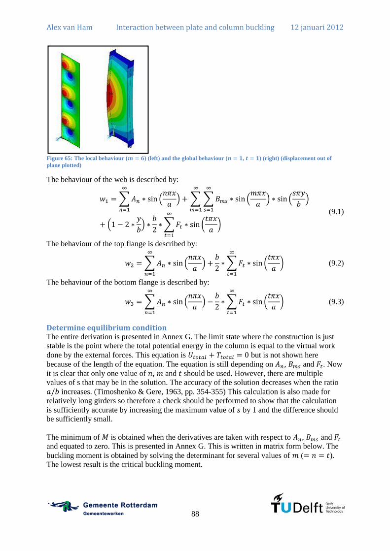
Alex van Ham Interaction between plate and column buckling 12 januari 2012
88
Figure 65: The local behaviour ( ) (left) and the global behaviour ( , ) (right) (displacement out of
plane plotted)
The behaviour of the web is described by:
(9.1)
The behaviour of the top flange is described by:
(9.2)
The behaviour of the bottom flange is described by:
(9.3)
Determine equilibrium condition The entire derivation is presented in Annex G. The limit state where the construction is just
stable is the point where the total potential energy in the column is equal to the virtual work
done by the external forces. This equation is but is not shown here
because of the length of the equation. The equation is still depending on , and . Now
it is clear that only one value of , and should be used. However, there are multiple
values of s that may be in the solution. The accuracy of the solution decreases when the ratio
increases. (Timoshenko & Gere, 1963, pp. 354-355) This calculation is also made for
relatively long girders so therefore a check should be performed to show that the calculation
is sufficiently accurate by increasing the maximum value of by 1 and the difference should
be sufficiently small.
The minimum of is obtained when the derivatives are taken with respect to , and and equated to zero. This is presented in Annex G. This is written in matrix form below. The
buckling moment is obtained by solving the determinant for several values of ( ). The lowest result is the critical buckling moment.

Alex van Ham Interaction between plate and column buckling 12 januari 2012
89

Alex van Ham Interaction between plate and column buckling 12 januari 2012
90
Verification of the result To verify whether calculations have been done correctly, only the lateral-torsional buckling
behaviour is checked which means that .
(9.4)
This is the same as the matrix for lateral-torsional buckling (equation (2.34)). Therefore this is
correct. The verification for plate buckling can be done by calculating the theoretical buckling
factor of for a bending moment. This has been done and this is correct.
Results
Analytical results for flanges 150x15 mm and web 1500x15 mm The calculations have been done for a profile with very small flanges compared to the web.
This cross-section is extremely sensitive to the interaction of plate buckling and lateral-
torsional buckling.
Figure 66: Theoretical buckling curve for flanges 150x15 mm and web 1500x15 mm
In Figure 66 it is clear that the theoretical curve based on the interaction of plate buckling and
column buckling is well below the behaviour that is predicted by taking the minimum of plate
buckling and column buckling. In Figure 67 it is shown that the analytical calculations
underestimate the theoretical buckling load for small lengths. For longer lengths the
theoretical buckling load is always slightly overestimated but this may be solved by mesh
refinement.
0,0E+00
5,0E+08
1,0E+09
1,5E+09
2,0E+09
2,5E+09
3,0E+09
3,5E+09
4,0E+09
4,5E+09
5,0E+09
0 1000 2000 3000 4000
Critical bucklin
g m
om
ent [N
mm
]
Length of beam [mm]
Plate buckling
Lat-tor buckling
Ansys
Theoretical hinges

Alex van Ham Interaction between plate and column buckling 12 januari 2012
91
Figure 67: Difference caused by interaction of local and lateral-torsional buckling for flanges 150x15 mm and web
1500x15 mm
The results for a beam length of 2000 mm are given in Table 7.
Table 7: Buckling stress for beam with flanges 150x15 and web 1500x15 and length 2000
To illustrate the plate buckling behaviour also a plot is made of the displacement out of plane
in Figure 68. This is indeed the behaviour of a lateral displacement and a rotation which is the
global behaviour. Next to that behaviour also a local displacement of the web is observed.
This combination is indeed applied in Chapter 9.
-16,0%
-14,0%
-12,0%
-10,0%
-8,0%
-6,0%
-4,0%
-2,0%
0,0%
2,0%
4,0%
0 1000 2000 3000 4000
Diffe
rence [%
]
Length of beam [mm]
Theoretical hinges to Ansys
Calculation Buckling moment
Theoretical hinges
Column buckling
Plate buckling 4
Ansys model

Alex van Ham Interaction between plate and column buckling 12 januari 2012
92
Figure 68: Buckling of beam with flanges 150x15 and web 1500x15 and length 3000 (displacement out of plane
plotted)
Analytical results for flanges 500x25 mm and web 1500x15 mm The previous cross-section is not a very common cross-section because proper engineering
judgement would result in a cross-section with relatively large flanges and a slender web. For
this example flanges of 500x25 mm and a web of 1500x15 mm are applied.
Figure 69: Theoretical buckling curve for flanges 500x25 mm and web 1500x15 mm
0
2E+09
4E+09
6E+09
8E+09
1E+10
1,2E+10
1,4E+10
1,6E+10
1,8E+10
2E+10
0 2000 4000 6000 8000 10000
Critical bucklin
g m
om
ent [N
mm
]
Length of beam [mm]
Plate buckling
Lat-tor buckling
Ansys
Theoretical hinges

Alex van Ham Interaction between plate and column buckling 12 januari 2012
93
Figure 70: Difference caused by interaction of local and lateral-torsional buckling for flanges 500x25 mm and web
1500x15 mm
In Figure 69 the theoretical buckling curve is plotted and the difference between the
theoretical curve and the result in Ansys is given in Figure 70. It is clear that for shorter
lengths the theoretical buckling moment is underestimated due to the restraining effect of the
flanges which is not included in the analytical calculations.
For a column length of 9000 mm the results are given in Table 8.
Calculation Buckling stress
Theoretical hinges
Column buckling
Plate buckling
Ansys model Table 8: Buckling stress for column with flanges 500x25 and web 1500x15 and length 9000
Conclusion
General conclusion The buckling stress calculated using the analytical equations with hinged welds is always
lower than the plate buckling stress and the column buckling stress.
In the case of stiff flanges it is clear that the model using hinged welds is almost equal to the
minimum of the plate and column buckling stress. However, as seen in the model in Ansys, it
is clear that the buckling stress is much higher when plate buckling is governing because the
flanges prevent a large rotation at the welds.
The most important conclusion is that there is only interaction between the local and the
global behaviour if they have the same number of half-waves in the length of the column.
( in this thesis) This conclusion can be used later when the imperfections need to
be modelled to predict the real behaviour of an I-beam because the NEN-EN1993-1-5 does
-60,0%
-50,0%
-40,0%
-30,0%
-20,0%
-10,0%
0,0%
10,0%
0 2000 4000 6000 8000 10000 12000
Diffe
rence [%
]
Length of beam [mm]
Theoretical hinges to Ansys

Alex van Ham Interaction between plate and column buckling 12 januari 2012
94
not prescribe that these type of imperfections need to be modelled when calculating the
restraint of a class 4 I-beam.
Rotational restraint The buckling curve calculated has an important assumption that the flanges do not give any
rotational restraint to the web. This is realistic for I cross-sections with a relatively large width
of the web and flanges with a low rotational stiffness. It has been shown that the buckling
curve calculated is a good approximation of the buckling curve according to the model in
Ansys in those cases. However, when stiff flanges are applied the buckling curve is
underestimated.
Theoretical model The behaviour calculated now gives a proper inside in the way buckling happens in an I-
beam. It is clear that the buckling load is much better approximated using the method
described here but always requires a determinant of a matrix to be solved or an approximation
formula should be developed. It is questionable if this is necessary especially as it is a
combination of two buckling phenomena which have a completely different post-buckling
behaviour.

Alex van Ham Interaction between plate and column buckling 12 januari 2012
95
Chapter 10: I-beam according to the Eurocode and NEN NEN-EN1993-1-1 gives requirements on the design of steel structures. The requirements are
concerned with the static strength and the stability of steel structures. The static strength of
steel structures is not part of this thesis. Therefore the section on the stability of steel
structures is used here and applied upon the I-beam in bending. In NEN-EN1993-1-1 the
section 6.3 describes the calculation for stability of steel members. For the calculation of class
4 cross-sections a reference is made to NEN-EN1993-1-5 to calculate the effective cross-
section.
Stability of a welded I-beam under uniform bending moment
According to NEN-EN1993-1-1 A welded I-beam under uniform bending moment has to be checked using equation 6.46 from
NEN-EN1993-1-1:
(10.1)
In this case only the resistance is interesting and this is described by equation 6.48 from NEN-
EN1993-1-1 for class 4 cross-sections:
(10.2)
It is assumed that only the web has to be reduced for plate buckling. Therefore the minimum
requirement of the flanges is that:
(10.3)
For the calculation of NEN-EN1993-1-5 has to be considered. This calculation has been
shown before and is repeated here. The critical buckling stress for the web is: (assuming the
flanges are equal in dimensions)
(10.4)
Therefore the relative slenderness for plate buckling of the web is:
(10.5)
The reduction factor for plate buckling of the web is:
(10.6)
Using the effective cross-section (Figure 71) the effective moment of inertia can be
calculated. This formula is not given here. Then the effective section modulus can be
calculated which is needed for the resistance of the beam.

Alex van Ham Interaction between plate and column buckling 12 januari 2012
96
b/2
b/2
0,6
*ρ*b
/2
0,4
*ρ*b
/2
Figure 71: Effective cross-section for I-beam under uniform bending moment
According to equation 6.49 from NEN-EN1993-1-1 the relative slenderness of the I-beam is:
(10.7)
The critical buckling load is given by:
(10.8)
In the critical buckling load the warping term is often neglected. This is not applied here
because it is also not neglected in the real behaviour and in the FEM model later on. The
method for rolled cross-sections and equivalent welded cross-sections is used as it is
presented in NEN-EN1993-1-1 article 6.3.2.3. Using the relative slenderness the reduction
factor can be calculated using the following equation:
(10.9)
In which is:
(10.10)
The buckling curve depends on the dimensions of the welded I-section as given in Figure 72.
Figure 72: Choice of buckling curve according to NEN-EN1993-1-1 table 6.5 (in Dutch)
The factor is dependent on the buckling curve as given in Figure 73.

Alex van Ham Interaction between plate and column buckling 12 januari 2012
97
Figure 73: Factor dependent on the buckling curve chosen according to NEN-EN1993-1-1 table 6.1 (in Dutch)
Now the resistance can be calculated. This resulting resistance can be compared to the
calculations using FEM methods later on.
According to NEN6771 The old Dutch codes for the design of steel structures are the NEN6770 and the NEN6771.
The approach according to those codes is different and is also explained to show the major
difference in the calculation of a welded I-beam. The NEN6771 states that the reduction
factors for plate buckling and lateral-torsional buckling need to be determined for the gross
cross-section separately. Then the reduction factors need to be multiplied with the yield stress
and this is the maximum allowable stress in compression. This is the prescribed method.
The critical buckling stress for the plate is:
(10.11)
The critical moment for lateral-torsional buckling is based on the gross cross-section and is
given by:
(10.12)
The relative slenderness for the plate is:
(10.13)
The reduction factor for the stress in the plate is dependent on the slenderness of the plate.
(10.14)
Now the reduction factor is known it is possible to determine the relative slenderness.
(10.15)
The reduction factor for lateral-torsional buckling is calculated using:
(10.16)

Alex van Ham Interaction between plate and column buckling 12 januari 2012
98
The ultimate bearing capacity is therefore:
(10.17)

Alex van Ham Interaction between plate and column buckling 12 januari 2012
99
Chapter 11: I-beam in FEM The I-column has been calculated but also bending moments occur in real structures which
could lead to the instability of lateral-torsional buckling. The theoretical lateral-torsional
buckling load has been derived in Chapter 9 but in real structures there are also geometrical
imperfections and residual stresses which are represented by a single geometric imperfection
as explained for the I-column in Chapter 6. The single geometric imperfection is a global
deflection and rotation combined with a local displacement of the web.
The model is given in Figure 74. This is the same as Figure 64 except in FEM it is possible to
assume a fixed connection at the location of the welds and this is applied.
a
Mx
y
v
uM
θz
y
w1
tw
b
hf
tf
w3
w2
Figure 74: Welded I-beam in FEM
Displacement control vs Force control It has been described for the I-column that displacement control is applied at the end of the
beam to ensure that the stiff parts take the most loading. This is not possible for an I-beam. If
the displacement is specified at both ends as a linear displacement over the height of the beam
a tension part will develop in the web. The compressed flange will displace out of plane and
the tension flange will only increase in length due to axial strain. Therefore the compressed
flange will shorten more than the tension flange will lengthen. This means that the entire I-
beam will shorten at the centre line. However, it is not possible to include this in the model.
Therefore a load is applied at the ends of the I-beam. However, the end conditions are
modelled in such a way that the stiffest part of the cross-section carry the largest load. This is
described next.
Model description The model for axial compression as described before is the start of the model for bending
moments. The geometry remains unchanged but the boundary conditions at the end differ. As

Alex van Ham Interaction between plate and column buckling 12 januari 2012
100
explained before it is necessary to apply a load at the end of the beam. This is done at both
ends to ensure equilibrium. The end support is given in Figure 75. To ensure that the stiffer
parts take the most loading three very stiff beams are applied at the end and provide the
distribution as if there is thick end plate.
uz
Fx
Figure 75: Hinged beam support in 3D model. Displacement described at web and thick line is the very stiff beam.
The load is a linear line load. For a given bending moment, the load per node is calculated as
followed:
(11.1)
The value of the force is determined by the number of nodes in -direction ( ) and the
number of nodes on a single side of the flange ( ). This factor is calculated by assuming a
linear load distribution considering the individual leveller arms.
Single geometrical imperfections It has been shown for the I-column that the imperfections according to Chapter 4 do not give a
lower result than the imperfections according to the NEN-EN1993-1-5 using a single half
wave in the web and the imperfections according to the NEN-EN1993-1-5 using multiple half
waves in the web. Therefore the imperfections according to Chapter 9 are not included for the
I-beam.
The single geometric imperfection is a method to replace the real geometrical imperfections
and the residual stresses. For a welded I-beam the correct buckling curve depends on the
height to width ratio. If the ratio is larger than 2 the correct buckling curve is d and for a ratio
smaller than 2 the buckling curve is c. This influences the imperfections because for curve c
is the correct ratio and for curve d
is the correct ratio. This is not included and all
cross-sections are calculated using curve c and a ratio of
. This allows a better comparison
of the results.
Eurocode imperfections First the web is modelled with supports along its edges as described for a perfect plate. Then
the lowest eigenvalue is calculated and applied upon the plate with magnitude:
(11.2)

Alex van Ham Interaction between plate and column buckling 12 januari 2012
101
Figure 76: The local imperfection of the web according to the Eurocode
The factor is used because only the governing mechanism should be applied at full scale
and all other instability configurations may be scaled to 70% of the given limit. The major
displacement is the lateral-torsional buckling behaviour and plate buckling is the secondary
buckling mode.
Then the flanges are added to the construction and the entire model is loaded as described
before. The buckling load is the lateral-torsional buckling behaviour and is applied upon the
entire beam with magnitude equal to:
(11.3)
Figure 77: The global imperfection of the entire section according to the Eurocode
One should be aware that the maximum displacement is at the compressed flange. Therefore
the tension flange is only given a displacement lower than the maximum displacement. For
one case it has been investigated whether an imperfection in the form of a uniformly

Alex van Ham Interaction between plate and column buckling 12 januari 2012
102
compressed I-column is unfavourable but the difference was small. The imperfection in the
form of lateral-torsional buckling was slightly more unfavourable. NEN-EN1993-1-5 is not
clear about whether the maximum imperfection is at the compressed flange or as an average
for the cross-section. That would mean that the centre of the web is given the maximum
imperfection and then the cross-section is rotated which would result in a larger imperfection
at the compressed flange. It is applied such that the compressed flange is scaled to the
maximum imperfection.
The combination of the two displacements are applied to the construction and then the non-
linear calculation can be done.
Imperfections according to Eurocode using m=1 Another imperfection model is added which works the same as the previously described
model which generates imperfections according to the NEN-EN1993-1-5. However, it has
been shown in Chapter 9 that there is only interaction in the theoretical buckling load when
the number of half sine waves in the flanges is equal to the number of half sine waves in the
web. This is chosen at here.
Figure 78: The local imperfection of the web according to the Eurocode using
For this model the eigenvalues of the web are calculated and for each mode the total
deflection out of plane is calculated. The mode with the largest total imperfection out of plane
is applied at the web. (Figure 78) Then the flanges are added to the model and the buckling
modes are again calculated. For the buckling modes the total deflection out of plane is
calculated and the mode with the largest out of plane deflection is added to the entire column.
This is given in Figure 77.
Results Many cases using different dimensions for the flange and web have been calculated and the
results are presented in Annex I. Only for two configurations the results are presented and
discussed.
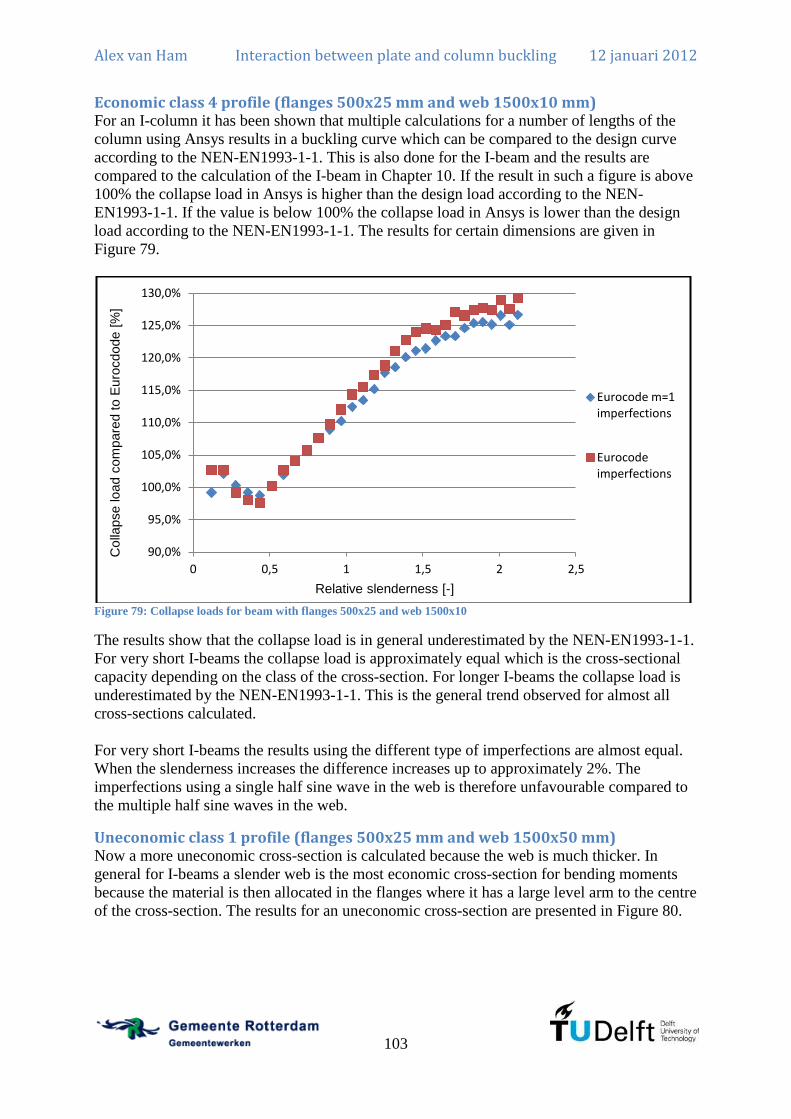
Alex van Ham Interaction between plate and column buckling 12 januari 2012
103
Economic class 4 profile (flanges 500x25 mm and web 1500x10 mm) For an I-column it has been shown that multiple calculations for a number of lengths of the
column using Ansys results in a buckling curve which can be compared to the design curve
according to the NEN-EN1993-1-1. This is also done for the I-beam and the results are
compared to the calculation of the I-beam in Chapter 10. If the result in such a figure is above
100% the collapse load in Ansys is higher than the design load according to the NEN-
EN1993-1-1. If the value is below 100% the collapse load in Ansys is lower than the design
load according to the NEN-EN1993-1-1. The results for certain dimensions are given in
Figure 79.
Figure 79: Collapse loads for beam with flanges 500x25 and web 1500x10
The results show that the collapse load is in general underestimated by the NEN-EN1993-1-1.
For very short I-beams the collapse load is approximately equal which is the cross-sectional
capacity depending on the class of the cross-section. For longer I-beams the collapse load is
underestimated by the NEN-EN1993-1-1. This is the general trend observed for almost all
cross-sections calculated.
For very short I-beams the results using the different type of imperfections are almost equal.
When the slenderness increases the difference increases up to approximately 2%. The
imperfections using a single half sine wave in the web is therefore unfavourable compared to
the multiple half sine waves in the web.
Uneconomic class 1 profile (flanges 500x25 mm and web 1500x50 mm) Now a more uneconomic cross-section is calculated because the web is much thicker. In
general for I-beams a slender web is the most economic cross-section for bending moments
because the material is then allocated in the flanges where it has a large level arm to the centre
of the cross-section. The results for an uneconomic cross-section are presented in Figure 80.
90,0%
95,0%
100,0%
105,0%
110,0%
115,0%
120,0%
125,0%
130,0%
0 0,5 1 1,5 2 2,5
Colla
pse load c
om
pare
d to E
uro
cdode [
%]
Relative slenderness [-]
Eurocode m=1 imperfections
Eurocode imperfections

Alex van Ham Interaction between plate and column buckling 12 januari 2012
104
Figure 80: Collapse loads for beam with flanges 500x25 and web 1500x50
For very short I-beams there are some numerical errors and these results should be treated
with caution. This is also the region where the Bernoulli assumption is not applicable. The
general trend is that the NEN-EN1993-1-1 verification is in accordance with the results from
Ansys. For a higher slenderness the difference increases slightly.
A more important conclusion is that the imperfections using a single half sine wave in the
web is unfavourable compared to multiple half sine waves in the web. The difference is
approximately 3% for a high slenderness.
Sensitivity analysis The model is applied in a number of cases but the sensitivity with respect to a number of
variables needs to be investigated. The buckling curves are applicable for many situations and
before conclusions are drawn on the basis of the previous results it is necessary to investigate
the sensitivity of the variables. The important variables that will be investigated are the yield
stress and the size of the imperfections.
Yield stress All previous results have been obtained using a yield stress of which is the most
common steel grade applied. However, in recent years higher strength steel is applied more
frequently and the sensitivity to the yield stress should be investigated. For the beam with
flanges 500x25 mm and web 1500x15 mm, using the imperfections in the NEN-EN1993-1-5,
the difference between the Ansys collapse load and the NEN-EN1993-1-5 verification is
plotted in Figure 81 for three different steel grades. ( , and )
90,0%
91,0%
92,0%
93,0%
94,0%
95,0%
96,0%
97,0%
98,0%
99,0%
100,0%
0 0,5 1 1,5 2 2,5
Colla
pse load c
om
pare
d to E
uro
code [
%]
Relative slenderness [-]
Eurocode m=1 imperfections
Eurocode imperfections

Alex van Ham Interaction between plate and column buckling 12 januari 2012
105
Figure 81: Sensitivity of non-linear analysis to yield stress
It is clear from Figure 81 that the yield stress does influence the behaviour and the safety level
is higher when the yield stress is higher. This is consistent with the NEN-EN1993-1-1 because
for many types of profiles S460 has a higher buckling curve so the reduction is smaller. This
is given in table 6.2 of NEN-EN1993-1-1. However, this is not true for welded I-beams so
here the same buckling curve is applied for all calculations.
Imperfections The single geometric imperfections are added to the structure according to the limits given in
the NEN-EN1993-1-5 for calculations using finite elements. These single geometric
imperfections represent the geometrical imperfections and the residual stresses. The question
is whether a slight increase or decrease of the single geometric imperfection results in a
considerable change of load bearing capacity. For the beam with flanges 500x25 mm and web
1500x15 mm the difference between the Ansys collapse load and the NEN-EN1993-1-1
verification is plotted in Figure 82 for three different imperfections. (1/150, 1/200 and 1/250)
Both the local imperfection of the web and the global imperfection of the entire cross-section
is changed.
90,0%
100,0%
110,0%
120,0%
130,0%
140,0%
150,0%
160,0%
170,0%
0,00 0,50 1,00 1,50 2,00 2,50 3,00 3,50
Colla
pse load c
om
pare
d to E
uro
code [
%]
Relative slenderness [-]
S355
S235
S460

Alex van Ham Interaction between plate and column buckling 12 januari 2012
106
Figure 82: Collapse load compared to Eurocode verification assuming different imperfection parameters.
90,0%
100,0%
110,0%
120,0%
130,0%
140,0%
150,0%
0 0,5 1 1,5 2 2,5
Colla
pse load c
om
pare
d to E
uro
code [
%]
Relative slenderness [-]
1/150 imperfection
1/200 imperfection
1/250 imperfection

Alex van Ham Interaction between plate and column buckling 12 januari 2012
107
Chapter 12: Comparison of analytical, FEM and Eurocode results for I-beam
General results For all cross-sections it is remarkable that in general the collapse load in Ansys is higher than
the collapse load according to the NEN-EN1993-1-1 verification. This is not the same
behaviour as for I-columns because there the collapse load in Ansys was always lower.
However, this can still be explained using the same criteria as for the I-column.
The most important one is that the single geometric imperfection is not equal to the
real structure with real geometric imperfections and residual stresses. The buckling
curves have been fitted to the test results for I-beams under uniform bending moment.
However, as shown in literature (Mateescu & Ungureanu), the results for I-beams are
slightly underestimated for higher slenderness’s.
The second is the effect of strain hardening which is present in real structures but not
in Ansys because a bilinear model has been used for the stress-strain diagram.
The NEN-EN1993-1-5 does not prescribe whether the maximum global displacement
which should be applied in the finite element model is an average maximum which
would mean that the centre of the web is given the prescribed displacement. If it is an
absolute maximum the compressed flange is given the maximum displacement. This is
applied here but the other method would result in lower collapse loads in Ansys.
Therefore it may be assumed that the results may be slightly different but the results are
certainly comparable to each other.
Influence ratio web to flange In the case of uniform compression on an I-column it was concluded that the ratio web to
flange is important for the bearing capacity. The NEN-EN1993-1-5 proved to be less
conservative when the web is relatively large compared to the flange. This relationship is also
examined for the I-beam. For a certain cross-section the web thickness is varied and the
collapse loads in Ansys are compared to the design loads according to the NEN-EN1993-1-5.
The results are given in Figure 83. One should be aware that for a thickness up to 18,1 mm the
cross-section is class 3 or lower so an elastic cross-sectional capacity should be used in the
verification. For a class 2 or higher a plastic cross-sectional capacity is allowed. Therefore the
larger difference between the thickness of 15 mm and the thickness of 20 mm is explained.

Alex van Ham Interaction between plate and column buckling 12 januari 2012
108
Figure 83: Collapse load compared to the Eurocode for flanges 500x25 mm and web with a width of 1500 mm
It is clear that the margins between the collapse loads in Ansys and the NEN-EN1993-1-5 is
larger when the thickness of the web is smaller. This is the same conclusion as drawn for the
case of uniform compression on an I-column.
However, for the case of a uniform bending moment on an I-beam no clear relationship has
been found as is done for the case of the I-column where the ratio of areas was a clear
parameter.
Influence type of imperfections Another remarkable effect is the difference between the three types of imperfections. The
imperfections according to Chapter 9 give a too small global imperfection for a low relative
slenderness because the local imperfection is governing and the global imperfection is scaled
down too much. This result was already found for the I-column and is not again investigated
for the I-beam.
The differences between the imperfections according to the Eurocode (using multiple half
sine waves in the web) and according to the Eurocode using (one single half sine wave
in the web) is calculated for only two cross-sections. It is clear that for an uneconomic cross-
section the difference is larger than for an economic cross-section. The web has a larger area
and therefore the difference is larger. In general the single half sine wave in the web is
unfavourable compared to the multiple half sine waves just as it was for the I-column.
90,0%
95,0%
100,0%
105,0%
110,0%
115,0%
120,0%
125,0%
130,0%
135,0%
0 0,5 1 1,5 2 2,5
Colla
pse load c
om
pare
d to E
uro
code [
%]
Relative slenderness [-]
t=10
t=15
t=20
t=25
t=30
t=35
t=40
t=45
t=50
Alex van Ham Interaction between plate and column buckling 12 januari 2012
109
Chapter 13: Conclusion, recommendations and future research
Conclusions First conclusions are drawn for the I-column and the interaction of column buckling and plate
buckling. Later the I-beam is discussed shortly because the results are in general similar to the
I-column. Structural engineers that need to design a class 4 cross-section are also advised to
read the recommendations.
Verification regulations The old Dutch codes for the verification of plate buckling (NEN6771) have strict regulations
and recommend the reduced stress method. This is a weakest link calculation and the post-
buckling strength is not exploited. The NEN-EN1993-1-5 provides a much more liberate
verification for plate buckling. The recommended method is the use of the effective width
method where the post-buckling strength is exploited and it is calculated as a parallel system
where the weakest link is not governing. Using a finite element method the results for I-
columns are verified and in general the results from the finite element analysis and the results
from the verification of the NEN-EN1993-1-1 are closely related. The differences for
commonly used cross-sections is in the order of 10-15%. The differences can be explained
because the finite element analysis has some simplifications concerning the residual stresses
and the geometric imperfections whereas the buckling curves are fitted to real test results.
Also verifications for plates including stiffeners is much more liberate in the NEN-EN1993-1-
5. The NEN6771 prescribes the use of a stiffener such that only individual plate panels may
buckle. The NEN-EN1993-1-5 verifies the stiffened plate panel using interaction formulas for
the individual sub-panels as well as for the entire stiffened panel.
Theoretical buckling load Analytical calculations have been performed to calculate the theoretical buckling load. This is
done using an energy method and virtual work. The assumed displaced shape is a combination
of the plate buckling and the column buckling shape. It is important to note that the post-
buckling behaviour is entirely different and therefore the understanding of the interaction is
more important than the actual value of the theoretical buckling load.
Interaction plate buckling and column buckling The most important conclusion from the analytical calculation is that there is only interaction
when the number of half sine waves in the web is equal to the number of half sine waves in
the entire column. The interaction is in general small for the theoretical buckling load. ( ) However, if the area of the web is large compared to the area of the flange, the
theoretical buckling load is significantly lower. ( )
Influence ratio web to flange The finite element analysis includes the effects of residual stresses and geometric
imperfections. These are included as a representative single geometric imperfection. The
finite element model is not an extremely advanced model and therefore the results should not
be seen as the exact answer for the collapse load but the results are especially suitable for a
comparative study.
The finite element analysis has been done on many cross-sections with different lengths.
From the results it is clear that the interaction is also present for structures with imperfections

Alex van Ham Interaction between plate and column buckling 12 januari 2012
110
and residual stresses. For a certain cross-section with a variable thickness of the web, the
difference between the finite element analysis and the NEN-EN1993-1-1 verification
increases when the thickness of the web increases. For an I-column under uniform
compression a relationship has been developed which describes the decrease of load bearing
capacity for a cross-section with a large web compared to the flanges. When the area of the
web is larger than the area of the flange a reduction factor is calculated in Chapter 7. The
reduction can be up to 20% for extremely uneconomic cross-sections. The results are
consistent with the results from the analytical calculation where the interaction of plate
buckling and column buckling is also only significant for uneconomic types of cross-sections.
Imperfection shape in finite element model The single geometric imperfection that is applied in the finite element analysis is a
representation of the geometric imperfection and the residuals stresses. The NEN-EN1993-1-5
prescribes the use of the global buckling shape and the local buckling shape combined in the
model. However, it has been shown that in general the local buckling shape can be made more
unfavourable if the web is displaced in a single half sine wave instead of multiple half sine
waves. This is not included in the NEN-EN1993-1-5. The difference is in general small
( ) but can be significant for very uneconomic cross-sections. ( )
Probabilistic design Using a probabilistic design method two types of cross-sections have been calculated. For an
economic cross-section it has been shown that the safety margin required ( ) in the
verification regulations is reached. ( ) For an uneconomic cross-section the safety
margin required is not reached. ( ) As stated before, the results should not be seen as
exact answers but the difference is striking. Only two cross-sections have been examined so
no general conclusions can be drawn from this analysis but apparently the safety is lower for
uneconomic types of cross-sections.
I-beam Not only I-columns have been studied. Also I-beams under uniform bending moment have
been studied. The results for those I-beams is very similar to the I-columns.
The finite element analysis results are slightly higher compared to the NEN-EN1993-
1-1 verification.
For the theoretical buckling load there is only interaction when the number of half sine
waves in the web is equal to the entire beam.
The theoretical buckling load is only significantly lower when the web is large
compared to the flanges.
The finite element results for an increasing thickness results in a reducing load bearing
capacity compared to the NEN-EN1993-1-1 verification.
Recommendations
Validate conclusions The most important recommendation is that experimental test results are needed to validate
the conclusions drawn before. The conclusions before are gained from results of a fairly
simple finite element model and analytical calculations. The finite element model and the
analytical calculations are consistent with each other and therefore the conclusions do seem
reasonable. However, to indicate whether the verification of these uneconomic type of cross-
sections has indeed a lower safety margin cannot be concluded based on only finite element
calculations. These test results could be used to set boundaries for the validity of the buckling

Alex van Ham Interaction between plate and column buckling 12 januari 2012
111
curves. Therefore experiments are necessary and this would be suitable for another master
thesis.
Also these results could be studied in a more advanced finite element model. The model used
does not include the residual stresses and geometrical imperfections as they really are but uses
a single geometric imperfection to replace the effects of those. Also a bilinear stress-strain
model has been used which could be refined by the use of the real stress-strain curve. It is
perhaps possible to validate such a model against existing test results and apply this also to
the more uneconomic cross-sections.
Design recommendation for structural engineer For the structural engineer it is recommended to use the verification method provided in the
NEN-EN1993-1-5 using the effective cross-section method. The finite element analysis shows
that the results are closely related and the NEN-EN1993-1-5 is based upon experimental
results. However, it is recommended to be wary of the assumptions done. Therefore some
general remarks are made which could be taken into consideration. For more information one
is recommended to read Chapter 3 of this thesis and other resources.
The effective cross-section method assumes a parallel system which means an
accumulation of the individual bearing capacities. The reduced stress method assumes
a serial system which means that the weakest link is governing.
For very uneconomic cross-sections the conclusions drawn before should be taken into
account. In general one is advised to optimize the cross-section such that the effects of
the uneconomic cross-section are removed. However, if this is not possible, it is
recommended to reduce the design resistance.
For the effective cross-section method stiffeners to the web are not very useful for the
static strength against axial compression and bending moments. In general the web is
slender and a stiffener only increases the area of the web that is effective. For axial
compression this is usually a small increase of the area and for bending moments the
material is close to the centre of gravity resulting in a small increase of the effective
section modulus.
It would be much more useful to apply larger flanges because the costs of adding a
stiffener are in general high in developed countries. The size of the web is only
decided by the fatigue loading, the shear force, the shear plate buckling stability and
the possibility of flange-induced buckling.
Future research There are several subjects which would be very interesting relating to the subject of plate
buckling. Some possibilities are mentioned here.
A very interesting and challenging subject is the interaction of plate buckling and
fatigue damage. This phenomena is called web breathing and a requirement is made in
the EN1993-2 which is the verification of steel bridges. The general problem is that if
a web often buckles and returns to its original shape secondary bending stresses occur
that cause fatigue damage.
o The verification regulation states that if the web is below a certain slenderness
no additional requirements are necessary. If the slenderness of the web is
above the limit, a verification has to be done using the reduced stress method.
This is a sharp boundary which could be refined. This is also only mentioned
in the verification of steel bridges. For other types of variable loading this is

Alex van Ham Interaction between plate and column buckling 12 januari 2012
112
not referred to. So the question also is, how many repetitive cycles is variable
loading.
o Also it states that the limiting slenderness is also valid for individual sub-
panels of stiffened panels. There are no requirements made for the stiffeners of
the web so an extremely small stiffener would be sufficient to prevent web
breathing according to the verification codes. This is not in accordance with
proper engineering judgement and regulations could be developed to derive a
minimum size of the stiffener.
The imperfections could be examined much more accurately.
o First of all one could study whether the prescribed values in the NEN-EN1993-
1-5 for the single geometric imperfection are accurate. This value represents
the residual stresses and real geometric imperfections and could possibly be
refined.
o Secondly, the sensitivity to the real geometric imperfections could be studied.
There are some situations where the geometric imperfection is larger than the
prescribed value that results from the fabrication tolerances. These should be
measured in practise. This may for example be the case in closed box girders
that are subject to overpressure on the inside. Question is whether this
significantly lowers the bearing capacity of the box girder.

Alex van Ham Interaction between plate and column buckling 12 januari 2012
113
References Abspoel, R., & Bijlaard, F. (2005). Steel Structures 3 (Part: Stability of Steel Plate
Structures). Delft: TU Delft.
Beg, D., Kuhlmann, U., Davaine, L., & Braun, B. (2010). Design of Plated Structures. ECCS.
Bijlaard, F. (1982). The design of transverse and longitudinal stiffeners for stiffened plate
panels. Rijswijk: Heron.
Burg, M. v. (2011). Plate buckling in design codes. Delft: TU Delft.
Civil park. (2011). Civil engineering formulas. Retrieved from s1.civilpark.com
ECCS. (2007). Commentary and worked examples to EN 1993-1-5 "Plated Structural
Elements".
EN10029. (1991). EN10029: Warmgewalste staalplaat van 3 mm of dikker. Toleranties op
afmetingen, vorm en massa .
FEA Optimization. (2011). Column buckling background information. Retrieved from
www.fea-optimization.com
Hoogenboom, P. (2010). Aantekeningen over wringing. Delft: TU Delft.
Mateescu, D., & Ungureanu, V. Lateral-torsional buckling of steel beams.
NEN6770. (1997). TGB 1990 - Steel structures - Basic requirements and basic rules for
calculation of predominantly staticaly loaded structures .
NEN6771. (2000). TGB 1990 - Steel structures - Stability .
NEN-EN1090-2. (2008). Het vervaardigen van staal- en aluminiumconstructies - Deel 2:
Technische eisen voor staalconstructies .
NEN-EN1990. (2002). NEN-EN1990 Grondslagen van het constructief ontwerp .
NEN-EN1993-1-1. (2006). Eurocode 3: Design of steel structures – Part 1-1: General rules
and rules for buildings .
NEN-EN1993-1-5. (2006). Eurocode 3: Design of steel structures - Part 1-5: Plated
structural elements .
NEN-EN1993-2. (2007). NEN-EN1993-2: Design of steel structures - Part 2: Steel bridges .
Politecnico di Milano. (2011). Structural Steelwork Eurocodes, Development of a Trans-
national Approach. Retrieved from www.stru.polimi.it/en
Stichting CUR. (1997). CUR-publication 190: Probabilities in civil engineering, Part 1:
Probabilistic design in theory. Gouda: Stichting CUR.
Timoshenko, S., & Gere, J. (1963). Theory of elastic stability. McGraw-Hill.
University of Ljubljani. (2011). ESDEP Course (WG6, WG7 and WG8). Retrieved from
http://www3.fgg.uni-lj.si/
Vrouwenvelder, A. (2003). Structrural Stability. Delft: TU Delft.
Welleman, C. H. (2007). Constructiemechanica 3, Module: Stabiliteit van het evenwicht.
Delft: TU Delft.


Alex van Ham Interaction between plate and column buckling 12 januari 2012
115
List of figures Figure 1: Buckling of shells, columns and plates for geometrical (non)linear and physically
linear behaviour (University of Ljubljani, 2011) ..................................................................... 19 Figure 2: Effective width of a compressed plate (University of Ljubljani, 2011) ................... 21 Figure 3: Global buckling or column buckling (FEA Optimization, 2011) ............................. 22
Figure 4: Plate buckling or local buckling for a ratio of (displacement out of plane
plotted) ..................................................................................................................................... 22 Figure 5: Lateral-torsional buckling (Civil park, 2011) ........................................................... 23 Figure 6: Coordinate system 1 ................................................................................................. 24
Figure 7: Coordinate system 2 ................................................................................................. 24 Figure 8: Description of situation for column buckling ........................................................... 24
Figure 9: Description of situation for lateral-torsional buckling .............................................. 26
Figure 10: Description of situation for plate buckling ............................................................. 29 Figure 11: Derivation of the plate buckling load ..................................................................... 29
Figure 12: Plate buckling shape for and . .......................................................... 30 Figure 13: Buckling factor as a function of the aspect ratio for uniform compression ............ 30
Figure 14: The effective cross-section method for axial compression (NEN-EN1993-1-5,
2006)(p. 14) .............................................................................................................................. 31 Figure 15: Analogy to effective cross-section method (left, parallel system) and reduced stress
method (right, serial system) (Stichting CUR, 1997) ............................................................... 32
Figure 16: Cross-section for theoretical case between reduced stress and effective cross-
section method .......................................................................................................................... 33
Figure 17: Design of a class 4 cross-section ............................................................................ 34 Figure 18: Plate under uniform axial compression .................................................................. 35
Figure 19: Jump at slenderness of .................................................................................... 36 Figure 20: Process of checking I cross-section in Mathcad sheet ............................................ 38
Figure 21: Flange dimensions .................................................................................................. 40 Figure 22: Description of situation for uniform compression of welded I-column using hinged
welds ......................................................................................................................................... 42 Figure 23: Flow chart to derive the buckling load of an I-column .......................................... 42
Figure 24: The local behaviour ( , ) (left) and the global behaviour ( ) (right)
(displacement out of plane plotted) .......................................................................................... 43
Figure 25: Description of situation for uniform compression of welded I-column using fixed
welds ......................................................................................................................................... 47
Figure 26: Theoretical buckling curve for IPE200 ................................................................... 48 Figure 27: Difference caused by interaction of local and global buckling for IPE200 ............ 48 Figure 28: Theoretical buckling curve for flanges 150x15 mm and web 1500x15 mm .......... 49 Figure 29: Difference caused by interaction of local and global buckling for flanges 150x15
mm and web 1500x15 mm ....................................................................................................... 49
Figure 30: Buckling of column with flanges 150x15 and web 1500x15 and length 3000
(displacement out of plane plotted) .......................................................................................... 50 Figure 31: Theoretical buckling curve for flanges 500x25 mm and web 1500x15 mm .......... 51 Figure 32: Difference caused by interaction of local and global buckling for flanges 500x25
mm and web 1500x15 mm ....................................................................................................... 51
Figure 33: Choice of buckling curve according to NEN-EN1993-1-1 table 6.2 (in Dutch) .... 55
Figure 34: Factor dependent on the buckling curve chosen according to NEN-EN1993-1-1
table 6.1 (in Dutch) ................................................................................................................... 55 Figure 35: Design load for column with flanges 500x25 and web 1500x15 according to NEN
and Eurocode ............................................................................................................................ 57

Alex van Ham Interaction between plate and column buckling 12 januari 2012
116
Figure 36: Welded I-column in FEM ....................................................................................... 59 Figure 37: Flow chart of the process in FEM including the Ansys group commands ............. 60 Figure 38: Hinged column support in 3D model. Displacement described at web and thick line
is the very stiff beam. ............................................................................................................... 61
Figure 39: The local imperfection of the web according to the Eurocode ............................... 62 Figure 40: The global imperfection of the entire section according to the Eurocode .............. 62 Figure 41: Imperfection of the entire section according to Chapter 4 ..................................... 63
Figure 42: The local imperfection of the web according to the Eurocode using ......... 64 Figure 43: Load-in plane displacement graph for flanges 500x25 and web 1500x15 and length
10000 ........................................................................................................................................ 65 Figure 44: Load-out of plane displacement graph for flanges 500x25 and web 1500x15 and
length 10000 ............................................................................................................................. 65 Figure 45: Buckling curve including imperfections with flanges 500x25 and web 1500x15 .. 66 Figure 46: Collapse loads for column with flanges 500x25 and web 1500x15 ....................... 66
Figure 47: Percentual difference between Eurocode imperfections and Eurocode
imperfections ............................................................................................................................ 67 Figure 48: Collapse loads for column with flanges 150x15 and web 1500x15 ....................... 67
Figure 49: Percentual difference between Eurocode imperfections and Eurocode
imperfections ............................................................................................................................ 68 Figure 50: Sensitivity of non-linear analysis to yield stress ..................................................... 69
Figure 51: Collapse load compared to Eurocode verifications assuming different imperfection
parameters. ............................................................................................................................... 70
Figure 52: Method to combine geometric imperfection and residual stresses in FEM. ........... 71 Figure 53: Von Mises strains at maximum loading of I-column with flanges 500x50 and web
1500x10 and length 10000 ....................................................................................................... 72 Figure 54: Collapse load compared to the Eurocode for flanges 500x50 mm and web with a
width of 1500 mm .................................................................................................................... 73
Figure 55: Largest difference collapse load compared to Eurocode for flanges 500x50 mm and
web with a width of 1500 mm .................................................................................................. 73
Figure 56: Collapse load compared to Eurocode for several cases .......................................... 74
Figure 57: Collapse load compared to Eurocode as a function of ....................................... 74
Figure 58: Collapse load compared to Eurocode as a function of for restricted values ...... 75 Figure 59: Flow chart of the process in FEM for probabilistic analysis including the Ansys
group commands ...................................................................................................................... 77 Figure 60: Cumulative distribution of collapse load according to Ansys for economic cross-
section ....................................................................................................................................... 81 Figure 61: Significance of the design variables to the collapse load. ...................................... 81
Figure 62: Cumulative distribution of collapse load according to Ansys for uneconomic cross-
section ....................................................................................................................................... 83 Figure 63: Significance of the design variables to the collapse load. ...................................... 84
Figure 64: Description of situation for uniform bending moment of welded I-beam .............. 87
Figure 65: The local behaviour ( ) (left) and the global behaviour ( , ) (right)
(displacement out of plane plotted) .......................................................................................... 88 Figure 66: Theoretical buckling curve for flanges 150x15 mm and web 1500x15 mm .......... 90 Figure 67: Difference caused by interaction of local and lateral-torsional buckling for flanges
150x15 mm and web 1500x15 mm .......................................................................................... 91 Figure 68: Buckling of beam with flanges 150x15 and web 1500x15 and length 3000
(displacement out of plane plotted) .......................................................................................... 92 Figure 69: Theoretical buckling curve for flanges 500x25 mm and web 1500x15 mm .......... 92

Alex van Ham Interaction between plate and column buckling 12 januari 2012
117
Figure 70: Difference caused by interaction of local and lateral-torsional buckling for flanges
500x25 mm and web 1500x15 mm .......................................................................................... 93 Figure 71: Effective cross-section for I-beam under uniform bending moment ...................... 96 Figure 72: Choice of buckling curve according to NEN-EN1993-1-1 table 6.5 (in Dutch) .... 96
Figure 73: Factor dependent on the buckling curve chosen according to NEN-EN1993-1-1
table 6.1 (in Dutch) ................................................................................................................... 97 Figure 74: Welded I-beam in FEM .......................................................................................... 99 Figure 75: Hinged beam support in 3D model. Displacement described at web and thick line
is the very stiff beam. ............................................................................................................. 100 Figure 76: The local imperfection of the web according to the Eurocode ............................. 101 Figure 77: The global imperfection of the entire section according to the Eurocode ............ 101
Figure 78: The local imperfection of the web according to the Eurocode using ....... 102 Figure 79: Collapse loads for beam with flanges 500x25 and web 1500x10 ........................ 103 Figure 80: Collapse loads for beam with flanges 500x25 and web 1500x50 ........................ 104 Figure 81: Sensitivity of non-linear analysis to yield stress ................................................... 105
Figure 82: Collapse load compared to Eurocode verification assuming different imperfection
parameters. ............................................................................................................................. 106 Figure 83: Collapse load compared to the Eurocode for flanges 500x25 mm and web with a
width of 1500 mm .................................................................................................................. 108
Figure 84: Description of situation for plate buckling ........................................................... 121 Figure 85: Derivation of the plate buckling load ................................................................... 121
Figure 86: Bending energy of a plate (shaded area) ............................................................... 121
Figure 87: Bending of a plate in -direction .......................................................................... 122 Figure 88: Twisting of a plate ................................................................................................ 122
Figure 89: Rotation and elongation of an infinitesimal element ............................................ 124
Figure 90: Plate buckling shape for and ......................................................... 131
Figure 91: Buckling factor as a function of the aspect ratio for uniform compression .......... 132 Figure 92: Proces voor het toepassen van NEN-EN1993-1-5 (Burg, 2011) .......................... 134
Figure 93: Dimensions of the tool for checking class 4 cross-sections ................................. 139 Figure 94: Out of plane displacement at maximum loading. (left without stiffener, right with
stiffener) ................................................................................................................................. 142
Figure 95: Effective cross-section for I-beam under uniform bending moment .................... 144 Figure 96: Out of plane displacement at maximum loading. (left without stiffener, right with
stiffener) ................................................................................................................................. 146 Figure 97: Description of situation for uniform compression of welded I-column ............... 147 Figure 98: Flow chart to derive the buckling load of an I-column ........................................ 148
Figure 99: The local behaviour ( , ) (left) and the global behaviour ( ) (right)
(displacement out of plane plotted) ........................................................................................ 148 Figure 100: Situation for the welded I-column including rotational restraint........................ 161 Figure 101: Stresses at one end of the I-column .................................................................... 187
Figure 102: Displacement of I-column for first buckling mode ............................................ 189 Figure 103: Results using a fine and a coarse mesh ............................................................... 190
Figure 104: Results using a large and a small load step (lines overlap) ................................ 190 Figure 105: Von Mises stress at large displacement .............................................................. 191 Figure 106: Description of situation for uniform bending moment of welded I-beam .......... 203
Figure 107: Stresses at one end of the I-beam ....................................................................... 225 Figure 108: Results using a fine and a coarse mesh ............................................................... 226
Figure 109: Results using a large and a small load step ......................................................... 227 Figure 110: Von Mises stress at maximum loading ............................................................... 227

Alex van Ham Interaction between plate and column buckling 12 januari 2012
118

Alex van Ham Interaction between plate and column buckling 12 januari 2012
119
List of tables Table 1: Results using the reduced stress and the effective cross-section method .................. 33 Table 2: Buckling stress for column with flanges 150x15 and web 1500x15 and length 3000
.................................................................................................................................................. 50 Table 3: Buckling stress for column with flanges 500x25 and web 1500x15 and length 17500
.................................................................................................................................................. 51 Table 4: Margins on thickness (all dimensions in mm) of a steel plate according to EN10029
Table 1. ..................................................................................................................................... 78 Table 5: Design variables for economic I-column ................................................................... 80 Table 6: Design variables for uneconomic I-column ............................................................... 82
Table 7: Buckling stress for beam with flanges 150x15 and web 1500x15 and length 2000 .. 91 Table 8: Buckling stress for column with flanges 500x25 and web 1500x15 and length 9000
.................................................................................................................................................. 93
Table 9: Total reactions for all nodes ..................................................................................... 191 Table 10: Total reactions for all nodes ................................................................................... 228


Alex van Ham Interaction between plate and column buckling 12 januari 2012
121
Annex A: Derivation theoretical plate buckling load In Chapter 2 the theoretical plate buckling load is given. The derivation of this buckling load
is presented here. This is a modification of the derivation as it is presented in (Abspoel &
Bijlaard, 2005). An energy method is applied to calculate the buckling behaviour.
The aim is to determine the buckling load of a rectangular plate under a uniform loading from
one side as presented in Figure 84.
b
a
nxx nxxx
y
w
w
u
v
Figure 84: Description of situation for plate buckling
In a flow chart (Figure 85) the steps are given that will result in the buckling load.
Figure 85: Derivation of the plate buckling load
Internal energy First of all the internal energy due to bending strains of a plate needs to be determined. This is
caused by bending only. Shear strains and axial strains are neglected in this analysis because
they are small compared to the bending strains. For this an infinitesimal element of the plate
of size and is considered.
θ
M
Figure 86: Bending energy of a plate (shaded area)
Internal energy infinitesimal
element
External energy infinitesimal
element
Potential energy
equation
Differential equation
Expected deflection
shape
Evaluate bending energy
Evaluate external energy
Equate to find buckling load

Alex van Ham Interaction between plate and column buckling 12 januari 2012
122
The bending energy due to a bending moment is given by the shaded area in Figure 86:
(14.1)
Bending in x-direction
Mxx
x
y
Mxx
dx
dy
x
y Figure 87: Bending of a plate in -direction
The bending energy due to bending of the infinitesimal element is:
(14.2)
Bending in y-direction The same reasoning holds for the -direction.
(14.3)
Bending in xy-direction
Mxy
x
y
Mxy
dx
dy
x
y Figure 88: Twisting of a plate
The bending energy due to bending of the infinitesimal element is:
(14.4)
The evaluation of equation (14.4) results in:
(14.5)

Alex van Ham Interaction between plate and column buckling 12 januari 2012
123
Total bending energy The bending moments are related to the curvature in standard plate theory.
(14.6)
(14.7)
(14.8)
The formulas (14.6), (14.7) and (14.8) can be introduced in the derived formulas for the
bending energy in equations (14.2), (14.3) and (14.5).
(14.9)
(14.10)
(14.11)
The total internal energy is the summation of the above equations (14.9), (14.10) and (14.11)
integrated over the total area of the plate.
(14.12)
The result is:
(14.13)
This is the total internal energy due to bending in the plate.
External energy Now the external energy needs to be determined. This is the load multiplied by the
displacement. Only loading in -direction is present. An infinitesimal element is considered
which will displace and rotate and Pythagoras theorem is applied.

Alex van Ham Interaction between plate and column buckling 12 januari 2012
124
x
dx
u
u+u’dxw
w+w’dx
(1+ε)dx
Figure 89: Rotation and elongation of an infinitesimal element
Therefore the relation between strain and deformation of the element is:
(14.14)
The total strain of the element is considered to be negligible because the deformation will be
mostly in bending.
(14.15)
The energy is the stress at the end multiplied by the displacement at the end. The
displacement at the end is the derivative of the axial displacement integrated over the total
length.
(14.16)
Applying equation (14.15) to equation (14.16) gives:
(14.17)
Potential energy The sum of the internal energy and the external energy is the equation for the potential
energy.
Small
strains
Small compared
to

Alex van Ham Interaction between plate and column buckling 12 januari 2012
125
(14.18)
Differential equation By rewriting the potential energy equation the differential equation will be derived.
(14.19)
The equation is slightly changed into the following:
(14.20)
The first variation of P ( ) must be equal to zero to satisfy that the potential energy is
stationary.
(14.21)
Integration by parts will remove the derivatives behind the -symbol.

Alex van Ham Interaction between plate and column buckling 12 januari 2012
126
(14.22)
Evaluating this function will lead to this equation:
(14.23)
There are two solutions to equation (14.23). The variation of ( ) can be zero which is not
interesting. Therefore the differential equation is the result.
(14.24)
This is not the ordinary expression for the differential equation because is defined as a
compressive edge load. The ordinary expression uses as a tensile edge load which would
lead to a minus in front of the loading term.
Buckling load To derive the buckling load the equation for the potential energy is considered.
(14.25)
The bending energy needs to be equal to the virtual work applied. This means that is
the condition. The bending of the plate will be in the form of a double series of sine functions.
The factor is a constant which is the amplitude of the sinusoidal.
(14.26)
Bending energy First the equation for the bending energy is considered.
(14.27)
This equation is written in a different form which simplifies the calculation later on.
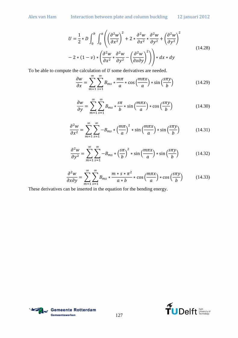
Alex van Ham Interaction between plate and column buckling 12 januari 2012
127
(14.28)
To be able to compute the calculation of some derivatives are needed.
(14.29)
(14.30)
(14.31)
(14.32)
(14.33)
These derivatives can be inserted in the equation for the bending energy.
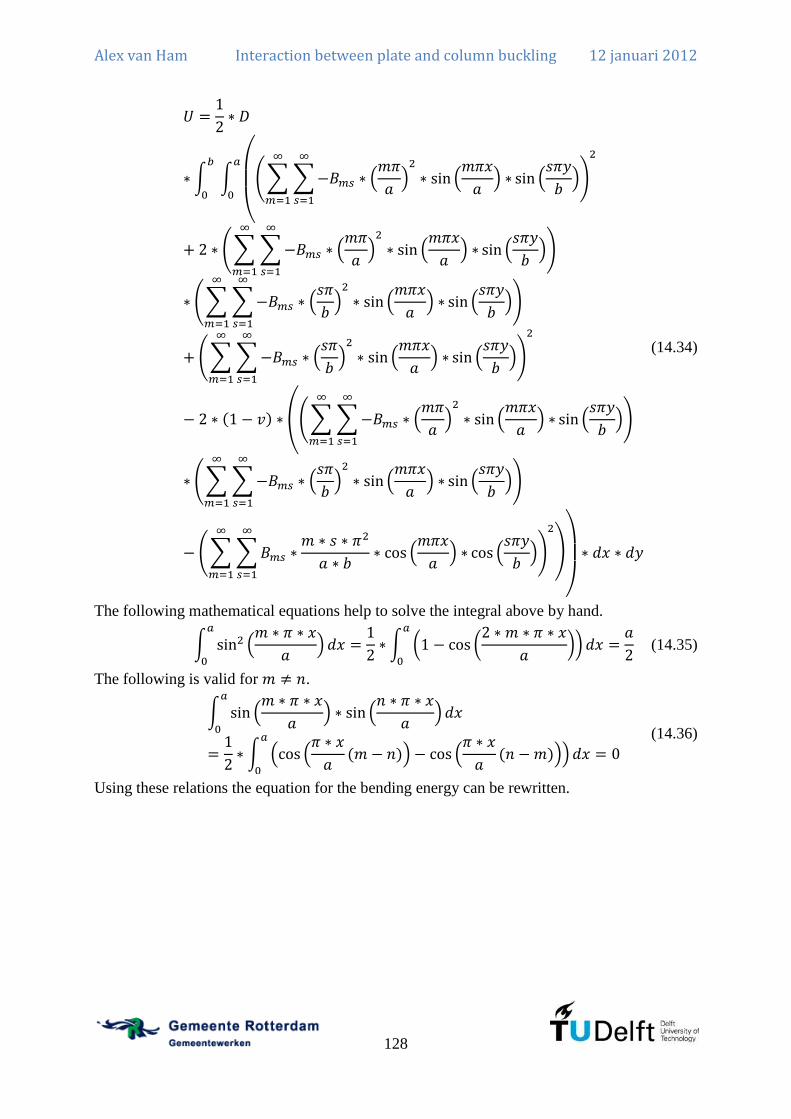
Alex van Ham Interaction between plate and column buckling 12 januari 2012
128
(14.34)
The following mathematical equations help to solve the integral above by hand.
(14.35)
The following is valid for .
(14.36)
Using these relations the equation for the bending energy can be rewritten.
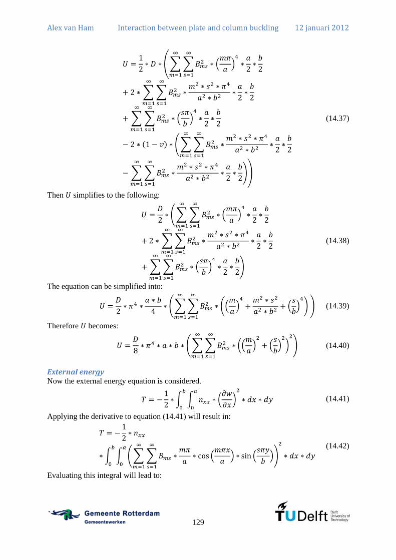
Alex van Ham Interaction between plate and column buckling 12 januari 2012
129
(14.37)
Then simplifies to the following:
(14.38)
The equation can be simplified into:
(14.39)
Therefore becomes:
(14.40)
External energy Now the external energy equation is considered.
(14.41)
Applying the derivative to equation (14.41) will result in:
(14.42)
Evaluating this integral will lead to:

Alex van Ham Interaction between plate and column buckling 12 januari 2012
130
(14.43)
Rewriting this equation will result into:
(14.44)
Combining equations Now the stability equation ( ) can be solved:
(14.45)
This results in the critical load:
(14.46)
The critical load is a minimum. The minimum of the function will be reached when all
values of are taken equal to zero except for one. Therefore the critical load will be:
(14.47)
Rewriting this equation results into the following:
(14.48)
As mentioned before, the critical load is a minimum. This will obviously be reached when
. This means there is a single half sine wave in transverse direction.
(14.49)
This equation has two parts. The first part is the column buckling load of a rectangular strip
with a length of and unit width. The load is also per unit width. The factor behind that term
is the increase of the buckling load due to the supports along the length of the column.
Now the equation can be rewritten again.
(14.50)
The aspect ratio of a plate is defined as:
(14.51)
This results in:

Alex van Ham Interaction between plate and column buckling 12 januari 2012
131
(14.52)
In which is the buckling factor:
(14.53)
The value of can be all real and positive integers so all buckling modes of the steel plate
are given by this equation. The value of determines the amount of half sine waves in a steel
plate when it buckles. In Figure 90 the buckling mode with and is presented.
Figure 90: Plate buckling shape for and
The buckling factor is dependent on the aspect ratio of the plate and the number of half sine
waves and this can be plotted in a graph as done in Figure 91.
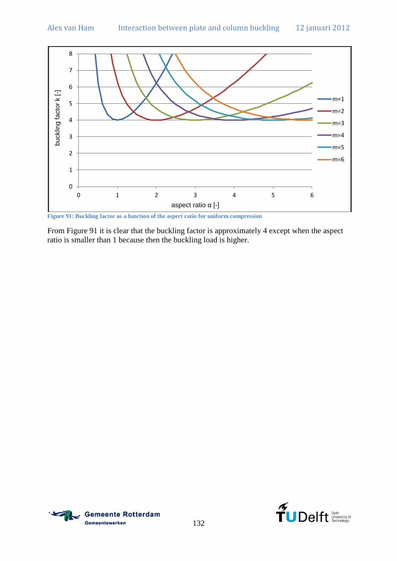
Alex van Ham Interaction between plate and column buckling 12 januari 2012
132
Figure 91: Buckling factor as a function of the aspect ratio for uniform compression
From Figure 91 it is clear that the buckling factor is approximately 4 except when the aspect
ratio is smaller than 1 because then the buckling load is higher.
0
1
2
3
4
5
6
7
8
0 1 2 3 4 5 6
bucklin
g f
acto
r k [-]
aspect ratio α [-]
m=1
m=2
m=3
m=4
m=5
m=6

Alex van Ham Interaction between plate and column buckling 12 januari 2012
133
Annex B: Tool for checking class 4 I cross-sections
Guide to tool (in Dutch)
Plooicontrole volgens NEN-EN1993-1-5 Dit document beschrijft de werking van de toetsingtool voor gelaste, klasse 4 I-profielen
volgens de NEN-EN1993-1-5. Voor een uitgebreide toelichting op de gebruikte norm en de
daarin toegepaste principes wordt verwezen naar literatuur. (Beg, Kuhlmann, Davaine, &
Braun, 2010) (Burg, 2011) (ECCS, 2007)
Deze is gebaseerd op de NEN-EN1993-1-5 en werkt op basis van de effectieve doorsnede
methode. Dit betekent dat voor elk deel een effectief oppervlak wordt bepaald en op basis
daarvan wordt de doorsnede getoetst als een klasse 3 profiel. Volgens art 4.3.3 en 4.3.4 mag
er op basis van alleen axiale druk een effectief oppervlak worden uitgerekend en op basis van
alleen een buigend moment een effectief weerstandsmoment worden uitgerekend. De
verplaatsing van het zwaartepunt ten gevolge van axiale druk wordt meegenomen. Van dit
principe is hier gebruik gemaakt dus de bepaling van de weerstand van de doorsnede hangt
niet af van de spanningsverdeling in de ligger.
In deze berekening wordt uitgegaan van een dubbelsymmetrisch profiel waarbij de momenten
om de horizontale as werken. In het geval van profielen met andere hoofdrichtingen dan de
verticale en horizontale dient er te worden nagegaan in hoeverre de berekening nog correct is.

Alex van Ham Interaction between plate and column buckling 12 januari 2012
134
Figure 92: Proces voor het toepassen van NEN-EN1993-1-5 (Burg, 2011)

Alex van Ham Interaction between plate and column buckling 12 januari 2012
135
Algemene factoren Hier worden de algemene factoren ingevoerd zoals de vloeisterkte en de elasticiteitsmodulus.
Invoer geometrie Hier wordt de geometrie van het I-profiel ingevoerd.
Verstijvingen van het lijf Als er geen verstijvingen aanwezig zijn, dienen de vinkjes bij die onderdelen te worden
uitgezet.
Verstijvingen zijn in deze sheet rechthoekige strips. Verstijvingen van het lijf zijn alleen
effectief voor plooistabiliteit van het lijf als ze in de drukzone zitten. Dit betekent dat ze niet
worden meegenomen als verstijvende werking als ze in de trekzone zitten. Daarna worden ze
wel meegenomen bij het bepalen van de effectieve doorsnedegrootheden. Verwaarlozen
betekent in dit geval dat ze automatisch worden weggelaten voor de weerstand tegen buigende
momenten als ze in de trekzone zitten.
Verstijvingen dienen altijd in dezelfde volgorde te worden ingevoerd. Dat betekent dat
verstijving 1 altijd dichter bij de bovenflens zit dan verstijving 2. Als er slechts één verstijving
aanwezig is, dient verstijving 1 te worden gebruikt. Uiteraard dienen de verstijvingen altijd
tussen de boven- en onderflens te worden geplaatst.
Fictieve boven- en of onderplaat Er is de mogelijkheid om een fictieve plaat in te voeren zoals bijvoorbeeld een betonnen dek.
Als deze niet aanwezig is, dan dienen de vinkjes bij die onderdelen te worden uitgezet.
Hiervoor dienen de oppervlakte, het eigen traagheidsmoment en de afstand van het hart van
de plaat tot de bovenkant van de ligger te worden ingevuld. Dit kan ook een negatieve afstand
zijn voor de bovenplaat maar de bovenplaat moet wel in de drukzone van het profiel zitten.
De onderplaat dient altijd te worden ingevuld zodanig dat deze in de trekzone zit onder. Als
het nodig is om twee verschillende boven- of onderplaten in te vullen dan kunnen deze
handmatig worden opgeteld en dan als één fictieve boven- of onderplaat worden ingevuld.
De reductiefactoren voor axiale druk en voor momenten zijn om respectievelijk de effectieve
oppervlakte en het effectieve eigen traagheidsmoment uit te rekenen.
Troggen Troggen kunnen ook worden ingevoerd. Er is de mogelijkheid om twee bovenplaten (troggen
1 en 2) en twee onderplaten (troggen 3 en 4) in te voeren. Alleen als er trogplaten aanwezig
zijn, dienen deze te worden aangevinkt. De troggen worden automatisch gereduceerd om de
effectieve doorsnede te bepalen alsof ze onderworpen zijn aan axiale druk. Dit is een
conservatieve benadering voor buigende momenten omdat er een klein spanningsverloop is
over de hoogte van de trog. Dit wordt hier verwaarloosd maar zou handmatig kunnen worden
toegevoegd als de troggen niet klein zijn ten opzichte van de totale hoogte van de ligger. Alle
platen worden gereduceerd voor axiale druk en de bovenplaten voor buigende momenten.
De trog wordt alleen gereduceerd op de individuele onderdelen en het globale knik- en/of
plooigedrag van de trogplaat als geheel en het effect van shear lag wordt niet berekend omdat
dit afhangt van de specifieke geometrie. Dit kan de effectieve doorsnede van de trogplaat
reduceren en dient dus bekeken te worden. De waarde van n geeft aan hoeveel troggen er
aanwezig zijn zoals getekend.

Alex van Ham Interaction between plate and column buckling 12 januari 2012
136
Shear lag effect Hier wordt shear lag berekend voor de boven- en onderflens van het profiel. Dit wordt gedaan
door de breedte te reduceren. Deze dient dan handmatig opnieuw te worden ingevoerd direct
onder dit blok. Shear lag wordt niet berekend voor de verstijvingen, fictieve platen en de
troggen. Hier dient zelf een keuze in te worden gemaakt door deze verstandig te kiezen of
door deze handmatig correct bij de geometrie in te voeren.
Bruto doorsnede eigenschappen Hier wordt het oppervlak, zwaartepunt en traagheidsmoment van de bruto doorsnede
berekend.
Reduceren doorsnede flenzen t.g.v. axiale druk Hierbij worden de flenzen gereduceerd voor axiale druk dus elk plaatdeel wordt onder
uniforme druk berekend.
Lijf (Druk) Daarna wordt voor het lijf de reductie toegepast voor 0, 1 en 2 verstijvingen ten gevolge van
axiale druk en daarbij worden ook de nieuwe oppervlaktes, zwaartepunten en
traagheidsmomenten uitgerekend. Later wordt pas gekozen of er inderdaad verstijvingen
aanwezig zijn. Dan wordt het juiste oppervlak, zwaartepunt en traagheidsmoment gekozen.
Reduceren doorsnede flenzen t.g.v. buigend moment De doorsnede reduceren voor buigende momenten werkt op een andere manier. Volgens art.
4.4.3 mag dit worden gedaan door eerst de gedrukte flens te reduceren voor buigende
momenten en dan vanuit de nieuwe spanningsverdeling het lijf te reduceren. Dit principe
wordt hier ook toegepast.
Eerst worden de bovenflenzen, de fictieve bovenplaat en de troggen 1 en 2 gereduceerd
waarbij dezelfde reductie is toegepast als voor axiale druk omdat het spanningsverloop over
de hoogte minimaal is. Daarna worden er nieuwe doorsnede eigenschappen bepaald met de
gereduceerde bovenflens. Dit is de basis voor de nieuwe spanningsverdeling.
Lijf (Moment) Daarmee wordt de spanningsverdeling in het lijf uitgerekend en op basis daarvan wordt het
lijf gereduceerd. De spanningsverdeling is dus niet de werkelijk aanwezige
spanningsverdeling maar de spanningsverdeling ten gevolge van alleen een buigend moment.
Na het reduceren van het lijf worden steeds de nieuwe oppervlaktes, zwaartepunten en
traagheidsmomenten bepaald en die worden dan weer later gekozen zoals dat ook voor axiale
druk werkt.
Reduceren lijf met verstijvingen Het reduceren van het lijf met verstijvingen is een ingewikkeld principe in de NEN-EN1993-
1-5. De gehele procedure wordt beschreven in annex A van NEN-EN1993-1-5. Dit werkt door
eerst de individuele delen te reduceren op basis van de spanningsverdeling. Dus van alle
subpanelen wordt een effectieve breedte bepaald. Daarna wordt naar het gehele plaatveld
gekeken waarbij de verstijvingen in het plaatveld aanwezig zijn. Deze verstijvingen met
meewerkende delen worden berekend als liggers met een verende ondersteuning van het lijf.
Daar zijn interactieformules om de plaatknik van de gehele plaat te bepalen. Dit levert een
reductiefactor op voor de plaat. Deze wordt toegepast op de dikte van de onderdelen die
worden beïnvloed door de verstijvingen. Dit zijn dus de subpanelen en de verstijvingen zelf

Alex van Ham Interaction between plate and column buckling 12 januari 2012
137
behalve de randen van de subpanelen die aan de flenzen zitten. Hierbij wordt er vanuit gegaan
dat torsieknik van de verstijvingen volledig wordt voorkomen. Dit zal later worden getoetst.
Bij het bepalen van de weerstand van het lijf met twee verstijvingen als “lumped stiffener”
wordt er vanuit gegaan dat deze zit op het zwaartepunt van de twee verstijvingen samen
inclusief de meewerkende delen. Als dus een van de veldafstanden klein is ten opzichte van
de andere veldafstanden kan deze aanname niet correct zijn.
Effectieve schuifkracht bepalen De effectieve schuifkracht wordt bepaald door een reductiefactor uit te rekenen voor het lijf.
Deze hangt af van de verstijvingen en wordt drie maal bepaald voor 0,1 en 2 verstijvingen.
Later wordt dan weer de juiste gekozen.
Lastintroductie Voor de lastintroductie is een aparte berekening toegevoegd en deze wordt meegenomen in de
toetsing van het profiel. Als er geen sprake is van lastintroductie kan de belasting op 0 worden
gezet.
ULS Toets De ULS toets zoekt de juiste eigenschappen afhankelijk van het aantal aanwezige
verstijvingen. Als er slechts 1 verstijving aanwezig is, dient altijd verstijving 1 te worden
gebruikt. Als verstijving 2 wordt aangevinkt, is verstijving 1 ook altijd actief.
Hier wordt ook bepaald of een verstijving in de trekzone ligt van het profiel en als dat zo is
dan wordt die verwaarloosd voor de bepaling van de weerstand tegen plooien van het lijf.
Daarna worden de interactie formules voor axiale druk, buigende momenten en schuifkracht
toegepast zoals die in artikel 7.1 en 7.2 staan. Hierbij wordt in principe uitgegaan van
krachten en momenten uit een tweede-orde berekening. Als een eerste-orde berekening wordt
toegepast dient er te worden gerekend volgens NEN-EN1993-1-1 waarbij knik en kip
berekeningen dienen te worden gedaan met de effectieve doorsnedegrootheden.
SLS toets Bij de SLS toets (gereduceerde spanningen methode) wordt voor de individuele subpanelen
van het lijf een reductiefactor uitgerekend op basis van de echte spanningen die aanwezig zijn.
Dit wordt berekend conform artikel 10 uit NEN-EN1993-1-5. Daarna wordt aan de hand van
die reductiefactor de vloeisterkte verlaagd en dit wordt toegepast op het bruto profiel. Deze
toets zal altijd gelijk zijn of hoger uitkomen als/dan de gereduceerde doorsnede methode bij
gelijke belasting. Hierbij wordt dus niet gekeken of de verstijvingen voldoen aan de eisen die
nodig zijn om alleen individuele subpanelen te toetsen. Ook wordt niet bekeken of de flenzen
wellicht een grotere reductiefactor hebben. Dit is dus meer ter indicatie of de individuele
panelen goed zijn gekozen of dat de onderlinge afstanden beter kunnen worden aangepast.
Eigenlijk moet op basis van de geometrie van de plaat met verstijvingen een kritische
knikspanning worden bepaald. Dit kan bijvoorbeeld met het programma EBPlate wat gratis
beschikbaar is op internet. Aan de hand van die kritische spanning kan direct de plaat worden
getoetst volgens de gereduceerde spanningen methode. Dit is niet verwerkt in de tool omdat
de tool gemaakt is voor de uiterste grenstoestand. De gereduceerde spanningen toets is slechts
ter indicatie van de individuele plaatdelen in het lijf.

Alex van Ham Interaction between plate and column buckling 12 januari 2012
138
Ook wordt hier de spanning getoetst alsof het een klasse 3 profiel is in de uiterste vezel van
het profiel. Deze spanning is vooral om een indicatie te hebben of het überhaupt mogelijk is
om de doorsnede te laten voldoen met de huidige geometrie uitgaande van een volledig
effectieve doorsnede. Hierbij wordt de schuifspanning in het lijf opgeteld omdat de axiale
spanning in het lijf nauwelijks kleiner is dan de axiale spanning in de uiterste vezel. Dit is dus
een conservatieve benadering.
Flange induced buckling Het buigen van de ligger als geheel geeft een verticale kracht vanuit de flens op het lijf. Deze
spanning kan leiden tot het plooien van het lijf door die kracht. Daarom wordt er een
minimale eis gesteld aan het profiel. Daarbij wordt uitgegaan van vier aannames:
Symmetrische doorsnede. (Als de flenzen niet even groot zijn, wordt degene met het
grootste oppervlak gekozen. Hiermee wordt de berekening niet geheel correct
aangezien deze ook van invloed zijn op de kromming.)
Maximaal 50% van de vloeisterkte als residuele spanning in de flenzen.
Beide flenzen vloeien volledig op het moment dat knik optreedt.
Weerstand tegen buiging wordt elastisch berekend.
Wanneer er verstijvingen zijn gelast aan het lijf is deze berekening niet correct maar wel
conservatief.
Torsiestijfheid van langsverstijvingen Langsverstijvingen zijn volledig meegenomen in het bepalen van de effectieve doorsnede en
hoeven niet apart te worden uitgerekend voor de gegeven belasting. Bij deze berekening is er
wel van uitgegaan dat torsieknik niet kan optreden. Voor een strip als verstijving is er een
eenvoudige formule die de kritische torsieknikspanning bepaald. Als deze formule niet
voldoet, kan er voor worden gekozen om niet de vloeispanning als grens aan te houden maar
de actueel optredende spanning. (Beg, Kuhlmann, Davaine, & Braun, 2010, p. 139) Deze
wordt ook bepaald. De actuele spanning is hier met gebruik van de effectieve doorsnede
omdat dit ook de methode is die wordt gebruikt voor de berekening volgens de NEN-
EN1993-1-5.
Opmerkingen Verstijvingen van het lijf dienen daadwerkelijk verstijvingen te zijn en niet te zware
platen die een significante bijdrage leveren aan het constructief draagvermogen. Dit
komt omdat ze als dunwandige onderdelen worden uitgerekend.
Dwarsverstijvingen worden niet getoetst.

Alex van Ham Interaction between plate and column buckling 12 januari 2012
139
tt2.ttt1.t
tt3.t ht4
.t
tt4.t
bv2
bv1
ht3
.t
tw
t fbR
Afic.1
t fbL
t foR
t foL
ht
t v2
t v1
bfoL bfoR
bfbL bfbR
hv1
hv2
Ific.1zfic.1
zfic.2
Afic.2
Ific.2
bt1.i bt1.e
bt1.o
t t1.b
t t1.o
ht1
.t
zt1
.bk bt2.i bt2.e
bt2.o
t t2.b
t t2.o
ht2
.t
zt2
.bk
bt4.ibt4.e
bt4.o
t t4.b
t t4.o
zt4
.bk
bt3.ibt3.e
bt3.o
t t3.b
t t3.o
zt3
.bk
Figure 93: Dimensions of the tool for checking class 4 cross-sections

Alex van Ham Interaction between plate and column buckling 12 januari 2012
140
Tool The calculation tool is in total approximately 75 pages so this tool is not included here but is
included at the end in Annex J.
Validation of tool The tool is able to verify class 4 I cross-sections according to the verification rules given in
NEN-EN1993-1-5. The tool contains approximately 75 pages and is difficult to check
entirely. There is always a risk of interpretation errors, certain configurations that do not fit
the assumptions, typing errors or errors in the NEN-EN1993-1-5. No guarantees can be given
that these errors are removed but some checks are done to validate the tool. Ansys is used to
calculate a certain configuration with and without a stiffener included. The results according
to Ansys can be compared to the calculations according to the NEN-EN1993-1-5.
Validation of compressed plate with two stiffeners In literature (Beg, Kuhlmann, Davaine, & Braun, 2010, pp. 68-71) calculations have been
performed on a plate with two stiffeners in uniform compression. The dimensions of the plate
are 1800x12 mm and the stiffeners are at equivalent distances of 600 mm and the dimension
of the stiffeners is 100x10 mm.
In literature the critical plate buckling stress is computed of the global plate. This is done
according to the NEN-EN1993-1-5. The tool also computes these stresses and the results
should be equal.
The critical plate buckling stress of the plate for one stiffener is computed at:
The critical plate buckling stress of the lumped stiffener is computed at:
These stresses are also computed using the tool and the result for one stiffener is:
The result for the lumped stiffener is:
The results are almost equal because in the tool the assumption is made that the stiffener is a
thin-walled component. This assumption is also clearly stated in the guide so the user is aware
of the assumption.
I-column without stiffener This is a tool based on cross-sectional level and only takes into account plate buckling.
Therefore also a hand calculation needs to be included to calculate the column buckling
behaviour according to the NEN-EN1993-1-5. The chosen cross-section has a web of
1500x10 mm, flanges of 500x50 mm and a length of 10000 mm. The stiffener is a rectangular
strip of 80x6 mm. The strip is located at 750 mm of the compressed flange. The yield stress is
.
The calculation excluding a stiffener is as given in Chapter 5 so only the numerical results are
given here.
The critical buckling stress for the web is:

Alex van Ham Interaction between plate and column buckling 12 januari 2012
141
(15.1)
Therefore the relative slenderness for plate buckling in the web is:
(15.2)
The reduction factor for plate buckling of the web is:
(15.3)
Therefore the effective area of the I-column is the following:
(15.4)
This effective area is also calculated using the tool and this results in . The small
difference is caused by the effect that the calculation above uses the assumption of thin-
walled cross-sections. This assumption is not included in the tool.
According to equation 6.49 from NEN-EN1993-1-1 the relative slenderness of the I-column
is:
(15.5)
The critical buckling load is calculated using the gross cross-section and is given by:
(15.6)
Using the relative slenderness the reduction factor can be calculated using the following
equation:
(15.7)
In which is:
(15.8)
The design load therefore is:
(15.9)
The calculation has also been performed using Ansys and this results in:
(15.10)
The difference is therefore 9,6%. This is an acceptable difference as explained in Chapter 7.
I-column with one stiffener The calculation including one stiffener is as given in NEN-EN1993-1-5 so only the numerical
results are given here. The calculation of the effective area is done using the tool and results
in:
(15.11)
According to equation 6.49 from NEN-EN1993-1-1 the relative slenderness of the I-column
is:

Alex van Ham Interaction between plate and column buckling 12 januari 2012
142
(15.12)
The critical buckling load is calculated using the gross cross-section and is given by:
(15.13)
Using the relative slenderness the reduction factor can be calculated using the following
equation:
(15.14)
In which is:
(15.15)
The design load therefore is:
(15.16)
The calculation has also been performed using Ansys. The imperfections are the same as for
the case without any stiffeners. This results in:
(15.17)
The difference is therefore 10,9%. This difference is slightly larger so the increase of capacity
from 0 to 1 stiffener is smaller in Ansys than in the NEN-EN1993-1-5.
Figure 94: Out of plane displacement at maximum loading. (left without stiffener, right with stiffener)
The out of plane displacement at the maximum load is displayed in Figure 94. It is clear that
without any stiffeners the web will show buckles as predicted by the analytical calculation.
Even a small stiffener of 80x6 mm will prevent these buckles and forces the web to
participate in the load carrying behaviour. However, the increase of load bearing capacity is
only from to . This is an increase of 2,7% which is very small. The

Alex van Ham Interaction between plate and column buckling 12 januari 2012
143
additional amount of costs is probably not acceptable given the small increase of capacity.
One should therefore be alert when adding stiffeners and also consider the option of an
increased thickness of the web or of the flanges.
Only when plate buckling is not allowed, the use of stiffeners is probably useful. This is only
useful when the post-buckling capacity may not be explored. Relevant examples of these kind
of situations are fatigue loading, aesthetic reasons or large temperature differences.
I-beam without stiffener For the beam another cross-section is used with a thinner web. The chosen cross-section has a
web of 1500x8 mm, flanges of 500x50 mm and a length of 10000 mm. The stiffener is a
rectangular strip of 80x6 mm. The strip is located at 450 mm of the compressed flange. The
yield stress is
.
The calculation excluding a stiffener is as given in Chapter 10 so only the numerical results
are given here.
The critical buckling stress for the web is:
(15.18)
Therefore the relative slenderness for plate buckling in the web is:
(15.19)
The reduction factor for plate buckling of the web is:
(15.20)
Using the effective cross-section (Figure 95) the effective moment of inertia can be
calculated. This formula is not given here. Then the effective section modulus can be
calculated which is needed for the resistance of the beam.
(15.21)
This effective moment of inertia is also calculated using the tool and this results in . The small difference is caused by the effect that the calculation above uses the
assumption of thin-walled cross-sections. This assumption is not included in the tool.

Alex van Ham Interaction between plate and column buckling 12 januari 2012
144
b/2
b/2
0,6
*ρ*b
/2
0,4
*ρ*b
/2
Figure 95: Effective cross-section for I-beam under uniform bending moment
According to equation 6.49 from NEN-EN1993-1-1 the relative slenderness of the I-beam is:
(15.22)
The critical buckling load is given by:
(15.23)
In the critical buckling load the warping term is often neglected. This is not applied here
because it is also not neglected in the real behaviour and in the FEM model later on. The
method for rolled cross-sections and equivalent welded cross-sections is used as it is
presented in NEN-EN1993-1-1 article 6.3.2.3. In this validation of the tool the correct
buckling curve (d) is used in contradiction with the rest of this thesis where for all
calculations buckling curve c is used for comparative reasons.
Using the relative slenderness the reduction factor can be calculated using the following
equation:
(15.24)
In which is:
(15.25)
The design load therefore is:
(15.26)
The calculation has also been performed using Ansys. The imperfections are the same as for
the case without any stiffeners. This results in:
(15.27)
The difference is therefore 10,8%. This is an acceptable difference as explained in Chapter 12.

Alex van Ham Interaction between plate and column buckling 12 januari 2012
145
I-beam with one stiffener The calculation including one stiffener is as given in NEN-EN1993-1-5 so only the numerical
results are given here. The calculation of the effective moment of inertia is done using the tool
and results in:
(15.28)
According to equation 6.49 from NEN-EN1993-1-1 the relative slenderness of the I-beam is:
(15.29)
The critical buckling load is given by:
(15.30)
In the critical buckling load the warping term is often neglected. This is not applied here
because it is also not neglected in the real behaviour and in the FEM model later on. The
method for rolled cross-sections and equivalent welded cross-sections is used as it is
presented in NEN-EN1993-1-1 article 6.3.2.3. In this validation of the tool the correct
buckling curve (d) is used in contradiction with the rest of this thesis where for all
calculations buckling curve c is used for comparative reasons.
Using the relative slenderness the reduction factor can be calculated using the following
equation:
(15.31)
In which is:
(15.32)
The design load therefore is:
(15.33)
The calculation has also been performed using Ansys. The imperfections are the same as for
the case without any stiffeners. This results in:
(15.34)
The difference is therefore 11,5%. This difference is slightly larger so the increase of capacity
from 0 to 1 stiffener is larger in Ansys than in the NEN-EN1993-1-5.

Alex van Ham Interaction between plate and column buckling 12 januari 2012
146
Figure 96: Out of plane displacement at maximum loading. (left without stiffener, right with stiffener)
The out of plane displacement at the maximum load is displayed in Figure 96. It is clear that
without any stiffeners the web will show buckles as predicted by the analytical calculation.
Even a small stiffener of 80x6 mm will prevent these buckles and forces the web to
participate in the load carrying behaviour. However, the increase of load bearing capacity is
only from to . This is an increase of 0,7% which is very small. The
additional amount of costs is probably not acceptable given the small increase of capacity.
One should therefore be alert when adding stiffeners and also consider the option of an
increased thickness of the web or of the flanges.
Only when plate buckling is not allowed, the use of stiffeners is probably useful. This is only
useful when the post-buckling capacity may not be explored. Relevant examples of these kind
of situations are fatigue loading, aesthetic reasons or large temperature differences.

Alex van Ham Interaction between plate and column buckling 12 januari 2012
147
Annex C: Analytical calculation of I-column under uniform compression without rotational restraint
Stability of a welded I-column under uniform compression A loss of stability of a welded I-column may occur in multiple ways. Local buckling may be
the governing mechanism which creates multiple half sine waves in the web. If local buckling
occurs the flanges are stiff enough to support the web. Local buckling is not a failure of the
entire structure. Global buckling of the entire column may be governing which would create a
single half sine wave in the weakest direction of the column. If global column buckling occurs
the flanges are not stiff enough to support the web. Global buckling is a failure mechanism.
However, also an intermediate form may occur which is an interaction between both forms.
The flanges are quite stiff but do not fully prevent local buckling.
This interaction is especially important for fatigue loaded structures. If a structure is loaded in
fatigue the post plate buckling strength may not be utilized so the strength is governed by the
lowest of the plate buckling strength and the column buckling strength. When either one is
much higher than the other, the lowest will be the governing mechanism. However, if they are
quite close to each other, there may be some interaction which is possibly unfavourable.
The calculation of the critical buckling stress of the welded I-column is equivalent to the
calculation made earlier for the plate simply supported along all four edges. Except this time
the local buckling behaviour is combined with the global buckling behaviour.
a
nxx nxxx
y
v
u
z
y
w1
tw
b
hf
tf
w2
Figure 97: Description of situation for uniform compression of welded I-column

Alex van Ham Interaction between plate and column buckling 12 januari 2012
148
The process to derive the buckling load is given in Figure 23.
Figure 98: Flow chart to derive the buckling load of an I-column
Deflection shape as a sum of global and plate buckling behaviour The deformation shape of the column may be described in the following way. For the global
behaviour a series of half sines is used and for the local behaviour a series of half sines
multiplied by another series of half sines in transverse direction is used. These deformations
are the ones of the individual buckling shapes of the global and the local behaviour. The
deformation of the web ( ) is a summation of the local and the global behaviour. The
deformation of the flange ( ) is described by the global behaviour. At and the
web and the flange have the same deformation for all so compatibility between the web and
the flange is ensured.
Therefore the deformation shape is given in Figure 99.
Figure 99: The local behaviour ( , ) (left) and the global behaviour ( ) (right) (displacement out of
plane plotted)
The deformation shape of the web is:
(16.1)
The deformation shape of the flanges is:
(16.2)
Expected deflection shape
Potential energy in web
Potential energy in flanges
Total potential energy
Virtual work done on web
Virtual work done on flanges
Total virtual work done
Equate potential energy to virtual
work done
Derivatives to scaling
parameters
Solve determinant of
matrix Buckling load

Alex van Ham Interaction between plate and column buckling 12 januari 2012
149
Flanges normally have a moment-resistant connection to the flanges. However, the flanges
have a very small resistance to rotation for smaller flanges which are important for this thesis.
Timoshenko (1963) described the buckling behaviour of columns and plates separately using
an energy method. The strain energy in the construction needs to be smaller than the virtual
work done by the external forces to ensure that the construction is stable. This is again similar
to the applied derivation of the plate buckling load earlier. However, this thesis combines the
effects of local and global buckling.
Determine potential energy in the web The potential energy in a plate can be described using the following equation.
(16.3)
Equation (16.3) can be written in a more convenient form to simplify calculations later on.
(16.4)
First some derivatives are computed to be able to calculate the potential energy.
(16.5)
(16.6)
(16.7)
Several derivates need to be squared. These are computed here.

Alex van Ham Interaction between plate and column buckling 12 januari 2012
150
(16.8)
(16.9)
(16.10)
(16.11)
General integration is needed to be able to calculate the integrals needed.
(16.12)
(16.13)
The following relationship is only applicable for .
(16.14)
For the following relations are applicable:

Alex van Ham Interaction between plate and column buckling 12 januari 2012
151
(16.15)
(16.16)
Using the general integrals, the terms of the potential energy can be computed. The triple
summations over and are only applicable if . If that part is equal to 0.
The third term of the first integral is only valid for .
(16.17)
(16.18)
(16.19)
The second part of this integral is only valid for and .
(16.20)
Therefore the potential energy in the web is the following result. The triple summations are
only applicable if . If that part is equal to 0. The terms with the triple
summations are only valid if .

Alex van Ham Interaction between plate and column buckling 12 januari 2012
152
(16.21)
Simplification of this results into the bending energy in the web. The triple summations over
and are only applicable if . If that part is equal to 0. The third term of this
integral is only applicable for .
(16.22)
Determine potential energy in the flange The potential energy in both flanges can be described using the following equation.
(16.23)
First the derivative is computed to be able to calculate the potential energy.
(16.24)
The derivate needs to be squared. This is computed here.
(16.25)
Using the general integrals, the terms of the potential energy can be computed.
(16.26)

Alex van Ham Interaction between plate and column buckling 12 januari 2012
153
Therefore the potential energy in both flanges combined is the following:
(16.27)
Total potential energy in the welded I-column The results for the potential energy in the web (equation (16.22)) and in the flanges (equation
(16.27)) can be combined and results in the total potential energy in the welded I-column. The
triple summations are only applicable if . If that part is equal to 0. The third
term is only applicable for .
(16.28)
This is simplified into the following where the triple summations are only applicable if . If that part is equal to 0. The third term is only applicable for .
(16.29)
Virtual work done by the external forces on the web The virtual work done by the external forces on the web can be described using the following
equation.
(16.30)
First the derivative is computed to be able to calculate virtual work.
(16.31)
The derivative needs to be squared. This is computed here.

Alex van Ham Interaction between plate and column buckling 12 januari 2012
154
(16.32)
Using the general integrals, the terms of the virtual work can be computed. The triple
summations are only applicable if . If that part is equal to 0. The third term is
only applicable for .
(16.33)
Therefore the virtual work done on the web is the following result. The triple summations are
only applicable if . If that part is equal to 0. The third term is only applicable
for .
(16.34)
Virtual work done by the external forces on the flange The virtual work done by the external forces on both flanges can be described using the
following equation.
(16.35)
First the derivative is computed to be able to calculate virtual work.
(16.36)
The derivative needs to be squared. This is computed here.

Alex van Ham Interaction between plate and column buckling 12 januari 2012
155
(16.37)
Using the general integrals, the terms of the virtual work can be computed.
(16.38)
Therefore the virtual work done on both flanges combined is the following result.
(16.39)
Virtual work done by the external forces on the welded I-column The results for the virtual work done on the web (equation (16.34)) and on both flanges
(equation (16.39)) can be combined and results in the total virtual work done on the welded I-
column. The triple summations are only applicable if . If that part is equal to 0.
The third term is only applicable for .
(16.40)
This is simplified into the following where the triple summations are only applicable if . If that part is equal to 0. The third term is only applicable for
(16.41)
Determine equilibrium condition The limit state where the construction is just stable is the point where the total potential
energy in the column is equal to the virtual work done by the external forces. If the load is
increased anymore at this point the structure will buckle. The triple summations are only
applicable if . If that part is equal to 0.
(16.42)
From this equilibrium condition the buckling stress can be computed.

Alex van Ham Interaction between plate and column buckling 12 januari 2012
156
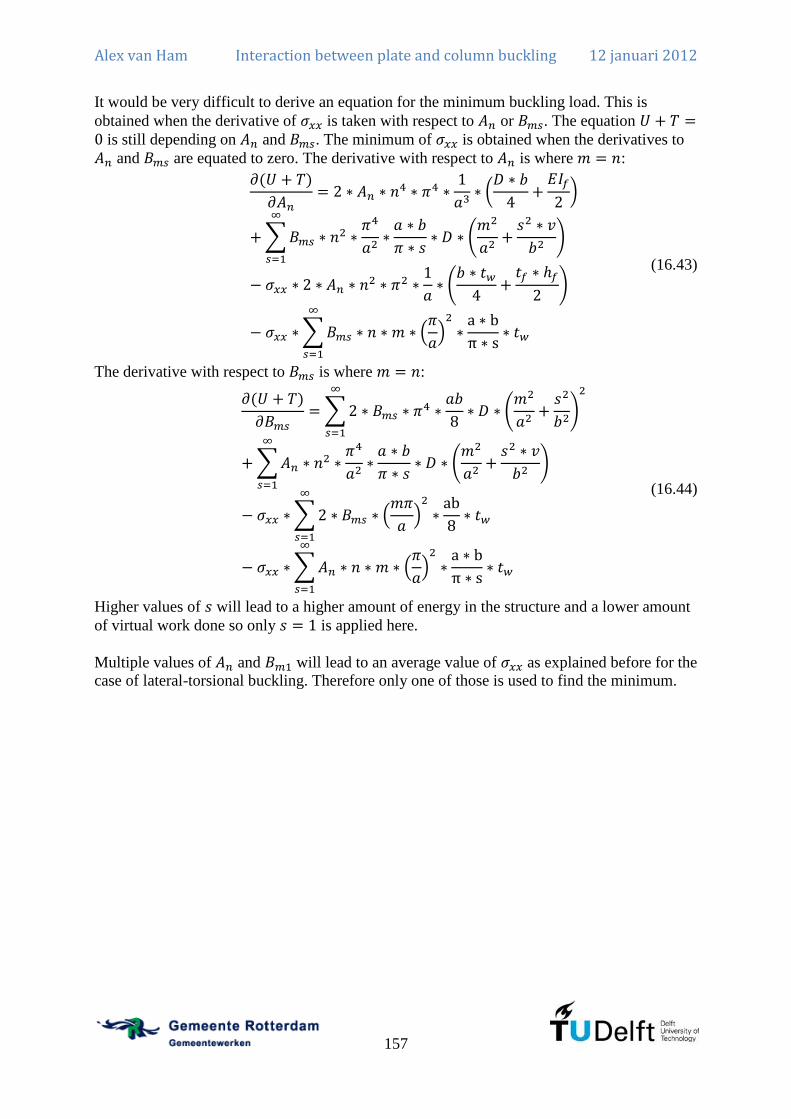
Alex van Ham Interaction between plate and column buckling 12 januari 2012
157
It would be very difficult to derive an equation for the minimum buckling load. This is
obtained when the derivative of is taken with respect to or . The equation is still depending on and . The minimum of is obtained when the derivatives to
and are equated to zero. The derivative with respect to is where :
(16.43)
The derivative with respect to is where :
(16.44)
Higher values of will lead to a higher amount of energy in the structure and a lower amount
of virtual work done so only is applied here.
Multiple values of and will lead to an average value of as explained before for the
case of lateral-torsional buckling. Therefore only one of those is used to find the minimum.

Alex van Ham Interaction between plate and column buckling 12 januari 2012
158
This can be written symbolically in the following way.
(16.45)
When the determinant is equated to zero and solved for this will result in the buckling stress.
(16.46)
Now it is applied that and .
(16.47)
This equation is only dependent on ( ). Therefore for the several buckling modes the buckling stress can be calculated. The
lowest value will result in the buckling stress.

Alex van Ham Interaction between plate and column buckling 12 januari 2012
159
It is also interesting to calculate the ratio of global to local buckling. The result of is
known so either equation of the matrix can be solved and this will result in the ratio of global
to local buckling.
(16.48)
Using the first equation of the matrix will result in:
(16.49)
Verification of the result To verify whether calculations have been done correctly, only the local buckling behaviour is
checked which means that . This means that the term in the second row and second
column is the only one that remains and is equated to zero.
(16.50)
This is slightly changed into the formula that is recognisable.
(16.51)
The result is indeed the traditional plate buckling formula that was derived earlier and that is
equation (14.52). Another way to verify is to assume only global buckling behaviour which
means that .
(16.52)
This is slightly changed into the formula that is recognisable.
(16.53)
This is the same as the known Euler buckling load (equation (2.18)) if n is chosen equal to 1:
(16.54)
This is also correct because this is the classical Euler buckling formula for columns which is
known from literature.


Alex van Ham Interaction between plate and column buckling 12 januari 2012
161
Annex D: Analytical calculation of I-column under uniform compression including rotational restraint The I-column under uniform compression has been calculated in Chapter 4 and Annex C
under the assumption that the welds are hinges. This assumption is safe but it is also possible
to include the rotational restraint of the welds. The configuration is described in Figure 100.
The only difference with Chapter 4 is that the rotation of the flange is included and only a
single half sine wave and a single cosine wave is included in the web in transverse direction.
The extended explanations are given in Annex C and here only the formulas are given as the
procedures is exactly alike.
a
nxx nxxx
y
v
u
z
y
w1
tw
b
hf
tf
w2
Figure 100: Situation for the welded I-column including rotational restraint
The deformation shape of the web is:
(17.1)
The deformation shape of the flange is:
(17.2)
The rotation of the flanges is calculated by differentiating to and applying or
which gives the same result except for the sign.
(17.3)

Alex van Ham Interaction between plate and column buckling 12 januari 2012
162
Determine potential energy in the web First the derivatives are needed:
(17.4)
(17.5)
(17.6)
Several derivates need to be squared. These are not shown. The integrals that need to be
calculated are given here:
(17.7)
(17.8)

Alex van Ham Interaction between plate and column buckling 12 januari 2012
163
(17.9)
(17.10)
Therefore the total potential energy in the web is:

Alex van Ham Interaction between plate and column buckling 12 januari 2012
164
(17.11)
The potential energy in the web is:

Alex van Ham Interaction between plate and column buckling 12 januari 2012
165
(17.12)
Determine potential energy in the flange The potential energy in the flange is the same as in Annex C with the addition of the
rotational resistance. This is calculated using:
(17.13)
The necessary derivatives are:
(17.14)
(17.15)
The integral results in:
(17.16)
So the total potential energy in the flange is:

Alex van Ham Interaction between plate and column buckling 12 januari 2012
166
(17.17)
Virtual work done by the external forces on the web The derivative needed is:
(17.18)
Integration will result in:
(17.19)
Therefore the total virtual work done on the web is:

Alex van Ham Interaction between plate and column buckling 12 januari 2012
167
(17.20)
Virtual work done by the external forces on the flange This is the same as the virtual work done on the flanges in Annex C. This is:
(17.21)
Determine equilibrium condition The equation gives the buckling load. However, it still depends on three variables.
Therefore the derivatives with respect to the variables , and need to be determined
and this can be represented in matrix form. Interaction only occurs when a single value of
( ) is chosen.

Alex van Ham Interaction between plate and column buckling 12 januari 2012
168
The matrix from which the determinant should be solved to find the buckling load is: ( )

Alex van Ham Interaction between plate and column buckling 12 januari 2012
169
Verification of result The matrix given of which the determinant should be solved is an expansion of the matrix that
was derived in Chapter 4 and Annex C. It is therefore only necessary to verify the result of the
web when it has clamped edges. ( and )
(17.22)
When this equation is solved to determine the buckling stress it results in:
(17.23)
The value of can be solved by taking the derivative of with respect to and equate this to
zero. This will result in:
(17.24)
Therefore the minimum buckling factor will be:
(17.25)
Literature (Timoshenko & Gere, 1963) provides the correct result for buckling with clamped
edges which is . Therefore the chosen cosine as the imperfection form is not exactly the
correct one but only results in an overestimation of the buckling load with 4,1%. As seen in
the results of Chapter 4 this is a proper estimate of the buckling load.


Alex van Ham Interaction between plate and column buckling 12 januari 2012
171
Annex E: Finite element model for I-column The model consists always of a main file where parameters can be changed. To run the model,
Ansys has to be started and the main file is loaded. The main file automatically refers to the
calculation file to repeat the calculation numerous times for a different column length. For
every calculation the following data is stored into a file:
Time
Displacement applied at the top of the column
Axial compressive force in the column
Displacement out of plane of the web
This file can be loaded into Excel for further processing.
Model using imperfections according to Eurocode
Main file finish
/clear
/batch,list
/filnam,plaatmodel
/title,plastisch gnl plaatmodel
/units,mpa
/nerr,1,99999999
/uis,msgpop,3
aint=1000
adelta=250
delta=50
tw=40
tf=25
b=250
hw=250
na=10
nb=40
nc=3
imp=200
imploc=200/0.7
nmax=100
buckm=100
fy=235
*do,i,1,delta,1
/input,c://acer/nonlinkolomv3impeurocode
disp,txt,,
*enddo
finish
/clear
Calculation file parsav,scalar,,
/clear
/batch,list
/filnam,plaatmodel
/title,plastisch gnl plaatmodel
/units,mpa
/nerr,1,99999999
/uis,msgpop,3
parres,new,,
a=aint+(i-1)*adelta
e=a/imp
eloc=b/imploc
dispmax=fy/210000*a*2
/view,,1,1,1
/prep7
et,1,shell181
r,1,tw
r,2,tf
et,2,beam4
r,3,1e2,1e9,1e9,100,100,0,0,100
mp,ex,1,2.1e5
mp,prxy,1,0.3
tb,biso,1
tbdata,1,fy,21
tbpl,biso,1
k,,0,0,0
k,,0,0,hw/2
k,,0,0,-hw/2
k,,b,0,0

Alex van Ham Interaction between plate and column buckling 12 januari 2012
172
k,,b,0,hw/2
k,,b,0,-hw/2
k,,0,a,0
k,,0,a,hw/2
k,,0,a,-hw/2
k,,b,a,0
k,,b,a,hw/2
k,,b,a,-hw/2
kplot
mshape,0
real,1
a,1,4,10,7
real,1
lsel,s,tan1,x,1
lsel,a,tan1,x,-1
lesize,all,,,na
lsel,s,tan1,y,1
lsel,a,tan1,y,-1
lesize,all,,,nb
asel,s,area,,1,1,1
amesh,all
nsel,s,loc,x,b/2
nsel,r,loc,y,0
nsel,r,loc,z,0
d,all,ux,0
nsel,s,loc,x,b/2
nsel,r,loc,y,a
nsel,r,loc,z,0
d,all,ux,0
nsel,s,loc,y,0
nsel,r,loc,z,0
d,all,uz,0
d,all,uy,0
nsel,s,loc,y,a
nsel,r,loc,z,0
d,all,uz,0
d,all,uy,-0.1
nsel,s,loc,x,0
nsel,a,loc,x,b
nsel,r,loc,z,0
d,all,uz,0
nsel,s,loc,x,b/2
d,all,ux,0
nmidmid=node(0.5*b,0.5*a,0)
nmiddenboven=node(0.5*b,a,0)
save
finish
/solve
antype,static
pstress,on
allsel
sbctran
solve
finish
/solve
antype,buckle
bucopt,lanb,1
mxpand,1
solve
finish
/post1
set,last
pldisp,1
plnsol,u,z,0,,
/wait,1
finish
/prep7
/inquire,myjobname,jobname
allsel
upgeom,eloc,1,1,'%myjobname(1)%',rst
save
real,2
a,1,2,8,7
a,1,3,9,7
a,4,5,11,10
a,4,6,12,10
real,3
l,1,2
l,1,3
l,4,5
l,4,6
l,7,8
Alex van Ham Interaction between plate and column buckling 12 januari 2012
173
l,7,9
l,10,11
l,10,12
real,2
lsel,s,tan1,y,1
lsel,a,tan1,y,-1
lesize,all,,,nb
lsel,s,tan1,z,1
lsel,a,tan1,z,-1
lesize,all,,,nc
real,2
asel,s,area,,2,5,1
amesh,all
real,3
lmesh,all
nsel,s,loc,y,0
nsel,a,loc,y,a
nsel,invert
ddele,all,uz
ddele,all,ux
nsel,all
d,all,roty,0
save
finish
/solve
antype,static
pstress,on
allsel
sbctran
solve
finish
/solve
antype,buckle
bucopt,lanb,buckm
mxpand,buckm
solve
finish
/post26
numvar,200
nsel,all
*get,nmin,node,0,nxth
*get,ntot,node,,count
nsol,3,nmin,u,z
*do,ndo,2,ntot
*get,nmin,node,nmin,nxth
nsol,196,nmin,u,z
add,3,3,196,,uz_tot
*enddo
*dim,uz_tot,array,buckm
vget,uz_tot(1),3
buckuz=uz_tot(1)
bucktoe=1
*do,j,2,buckm,1
*if,uz_tot(j),gt,buckuz,then
buckuz=uz_tot(j)
bucktoe=j
*else
*endif
*enddo
finish
/solve
antype,static
pstress,on
allsel
sbctran
solve
finish
/solve
antype,buckle
bucopt,lanb,bucktoe
mxpand,bucktoe
solve
finish
/post1
set,last
pldisp,1
plnsol,u,z,0,,
/wait,1
finish
/prep7
/inquire,myjobname,jobname
allsel
upgeom,e,1,bucktoe,'%myjobname(1)%',rs
t
Alex van Ham Interaction between plate and column buckling 12 januari 2012
174
nsel,all
ddele,all,rotz
ddele,all,roty
nsel,s,loc,y,a
ddele,all,uy,0
nsel,s,loc,y,a
nsel,r,loc,z,0
d,all,uy,-dispmax
save
finish
/solve
antype,static
nlgeom,on
outres,all,all
allsel
sbctran
nsubst,nmax,nmax,nmax
kbc,0
solve
save
finish
/post26
numvar,200
allsel
nsol,200,nmiddenboven,u,y,uyneg
filldata,199,,,,-1,0
prod,2,200,199,,uy
nsel,s,loc,y,0
*get,nmin,node,0,nxth
*get,ntot,node,,count
rforce,3,nmin,f,y
*do,ndo,2,ntot
*get,nmin,node,nmin,nxth
rforce,196,nmin,f,y
add,3,3,196,,fy_tot
*enddo
nsol,198,nmidmid,u,z,uz_echt
filldata,197,,,,e,0
add,4,198,197,,uz
save
*del,_p26_export
*dim,_p26_export,table,nmax,2
vget,_p26_export(1,0),1
vget,_p26_export(1,1),3
vget,_p26_export(1,2),4
/output,'blabla','','.',append
*vwrite,'time','uz'
%14c %14c %14c
*vwrite,_p26_export(1,0),_p26_export(1,1
),_p26_export(1,2)
%14.5g %14.5g %14.5g
/output,term
finish
Model using imperfections according to Eurocode using m=1
Main file finish
/clear
/batch,list
/filnam,plaatmodel
/title,plastisch gnl plaatmodel
/units,mpa
/nerr,1,99999999
/uis,msgpop,3
aint=1000
adelta=250
delta=50
tw=40
tf=25
b=250
hw=250
na=10
nb=40
nc=3
imp=200
imploc=200/0.7
nmax=100
buckm=250
buckmgl=100
fy=235
*do,i,1,delta,1

Alex van Ham Interaction between plate and column buckling 12 januari 2012
175
/input,c://acer/nonlinkolomv3impeurocode
dispmis1,txt,,
*enddo
finish
/clear
Calculation file parsav,scalar,,
/clear
/batch,list
/filnam,plaatmodel
/title,plastisch gnl plaatmodel
/units,mpa
/nerr,1,99999999
/uis,msgpop,3
parres,new,,
a=aint+(i-1)*adelta
e=a/imp
eloc=b/imploc
dispmax=fy/210000*a*2
/view,,1,1,1
/prep7
et,1,shell181
r,1,tw
r,2,tf
et,2,beam4
r,3,1e2,1e9,1e9,100,100,0,0,100
mp,ex,1,2.1e5
mp,prxy,1,0.3
tb,biso,1
tbdata,1,fy,21
tbpl,biso,1
k,,0,0,0
k,,0,0,hw/2
k,,0,0,-hw/2
k,,b,0,0
k,,b,0,hw/2
k,,b,0,-hw/2
k,,0,a,0
k,,0,a,hw/2
k,,0,a,-hw/2
k,,b,a,0
k,,b,a,hw/2
k,,b,a,-hw/2
kplot
mshape,0
real,1
a,1,4,10,7
real,1
lsel,s,tan1,x,1
lsel,a,tan1,x,-1
lesize,all,,,na
lsel,s,tan1,y,1
lsel,a,tan1,y,-1
lesize,all,,,nb
asel,s,area,,1,1,1
amesh,all
nsel,s,loc,x,b/2
nsel,r,loc,y,0
nsel,r,loc,z,0
d,all,ux,0
nsel,s,loc,x,b/2
nsel,r,loc,y,a
nsel,r,loc,z,0
d,all,ux,0
nsel,s,loc,y,0
nsel,r,loc,z,0
d,all,uz,0
d,all,uy,0
nsel,s,loc,y,a
nsel,r,loc,z,0
d,all,uz,0
d,all,uy,-0.1
nsel,s,loc,x,0
nsel,a,loc,x,b
nsel,r,loc,z,0
d,all,uz,0
nsel,s,loc,x,b/2
d,all,ux,0
nmidmid=node(0.5*b,0.5*a,0)

Alex van Ham Interaction between plate and column buckling 12 januari 2012
176
nmiddenboven=node(0.5*b,a,0)
save
finish
/solve
antype,static
pstress,on
allsel
sbctran
solve
finish
/solve
antype,buckle
bucopt,lanb,buckm
mxpand,buckm
solve
finish
/post26
numvar,200
nsel,all
*get,nmin,node,0,nxth
*get,ntot,node,,count
nsol,3,nmin,u,z
*do,ndo,2,ntot
*get,nmin,node,nmin,nxth
nsol,196,nmin,u,z
add,3,3,196,,uz_tot
*enddo
*dim,uz_tot,array,buckm
vget,uz_tot(1),3
buckuz=uz_tot(1)
bucktoe=1
*do,j,2,buckm,1
*if,uz_tot(j),gt,buckuz,then
buckuz=uz_tot(j)
bucktoe=j
*else
*endif
*enddo
finish
/solve
antype,static
pstress,on
allsel
sbctran
solve
finish
/solve
antype,buckle
bucopt,lanb,bucktoe
mxpand,bucktoe
solve
finish
/post1
set,last
pldisp,1
plnsol,u,z,0,,
finish
/prep7
/inquire,myjobname,jobname
allsel
upgeom,eloc,1,bucktoe,'%myjobname(1)%
',rst
save
real,2
a,1,2,8,7
a,1,3,9,7
a,4,5,11,10
a,4,6,12,10
real,3
l,1,2
l,1,3
l,4,5
l,4,6
l,7,8
l,7,9
l,10,11
l,10,12
real,2
lsel,s,tan1,y,1
lsel,a,tan1,y,-1
lesize,all,,,nb
lsel,s,tan1,z,1
lsel,a,tan1,z,-1
lesize,all,,,nc
real,2
asel,s,area,,2,5,1

Alex van Ham Interaction between plate and column buckling 12 januari 2012
177
amesh,all
real,3
lmesh,all
nsel,s,loc,y,0
nsel,a,loc,y,a
nsel,invert
ddele,all,uz
ddele,all,ux
nsel,all
d,all,roty,0
save
finish
/solve
antype,static
pstress,on
allsel
sbctran
solve
finish
/solve
antype,buckle
bucopt,lanb,buckmgl
mxpand,buckmgl
solve
finish
/post26
numvar,200
nsel,all
*get,nmin,node,0,nxth
*get,ntot,node,,count
nsol,3,nmin,u,z
*do,ndo,2,ntot
*get,nmin,node,nmin,nxth
nsol,196,nmin,u,z
add,3,3,196,,uz_tott
*enddo
*dim,uz_tott,array,buckmgl
vget,uz_tott(1),3
buckuz=uz_tott(1)
bucktoegl=1
*do,j,2,buckmgl,1
*if,uz_tott(j),gt,buckuz,then
buckuz=uz_tott(j)
bucktoegl=j
*else
*endif
*enddo
finish
/solve
antype,static
pstress,on
allsel
sbctran
solve
finish
/solve
antype,buckle
bucopt,lanb,bucktoegl
mxpand,bucktoegl
solve
finish
/post1
set,last
pldisp,1
plnsol,u,z,0,,
/wait,1
finish
/prep7
/inquire,myjobname,jobname
allsel
upgeom,e,1,bucktoegl,'%myjobname(1)%',
rst
nsel,all
ddele,all,rotz
ddele,all,roty
nsel,s,loc,y,a
ddele,all,uy,0
nsel,s,loc,y,a
nsel,r,loc,z,0
d,all,uy,-dispmax
save
finish

Alex van Ham Interaction between plate and column buckling 12 januari 2012
178
/solve
antype,static
nlgeom,on
outres,all,all
allsel
sbctran
nsubst,nmax,nmax,nmax
kbc,0
solve
save
finish
/post26
numvar,200
allsel
nsol,200,nmiddenboven,u,y,uyneg
filldata,199,,,,-1,0
prod,2,200,199,,uy
nsel,s,loc,y,0
*get,nmin,node,0,nxth
*get,ntot,node,,count
rforce,3,nmin,f,y
*do,ndo,2,ntot
*get,nmin,node,nmin,nxth
rforce,196,nmin,f,y
add,3,3,196,,fy_tot
*enddo
nsol,198,nmidmid,u,z,uz_echt
filldata,197,,,,e,0
add,4,198,197,,uz
save
*del,_p26_export
*dim,_p26_export,table,nmax,2
vget,_p26_export(1,0),1
vget,_p26_export(1,1),3
vget,_p26_export(1,2),4
/output,'blabla','','.',append
*vwrite,'time','uz'
%14c %14c %14c
*vwrite,_p26_export(1,0),_p26_export(1,1
),_p26_export(1,2)
%14.5g %14.5g %14.5g
/output,term
finish
Model using imperfections according to lowest buckling load
Main file finish
/clear
/batch,list
/filnam,plaatmodel
/title,plastisch gnl plaatmodel
/units,mpa
/nerr,1,99999999
/uis,msgpop,3
aint=12000
adelta=500
delta=29
tw=40
tf=30
b=1500
hw=500
na=10
nb=40
nc=3
eloc=200
eglob=200
nmax=100
fy=235
buckm=40
*do,i,1,delta,1
/input,c://acer/nonlinkolomv3,txt,,
*enddo
finish
Calculation file parsav,scalar,,
/clear
/batch,list
/filnam,plaatmodel
/title,plastisch gnl plaatmodel
/units,mpa
/nerr,1,99999999

Alex van Ham Interaction between plate and column buckling 12 januari 2012
179
/uis,msgpop,3
parres,new,,
a=aint+(i-1)*adelta
dispmax=fy/210000*a*2
/view,,1,1,1
/prep7
et,1,shell181
r,1,tw
r,2,tf
et,2,beam4
r,3,1e2,1e9,1e9,100,100,0,0,100
mp,ex,1,2.1e5
mp,prxy,1,0.3
tb,biso,1
tbdata,1,fy,21
tbpl,biso,1
k,,0,0,0
k,,0,0,hw/2
k,,0,0,-hw/2
k,,b,0,0
k,,b,0,hw/2
k,,b,0,-hw/2
k,,0,a,0
k,,0,a,hw/2
k,,0,a,-hw/2
k,,b,a,0
k,,b,a,hw/2
k,,b,a,-hw/2
kplot
mshape,0
real,1
a,1,4,10,7
real,2
a,1,2,8,7
a,1,3,9,7
a,4,5,11,10
a,4,6,12,10
real,3
l,1,2
l,1,3
l,4,5
l,4,6
l,7,8
l,7,9
l,10,11
l,10,12
real,1
lsel,s,tan1,x,1
lsel,a,tan1,x,-1
lesize,all,,,na
lsel,s,tan1,y,1
lsel,a,tan1,y,-1
lesize,all,,,nb
lsel,s,tan1,z,1
lsel,a,tan1,z,-1
lesize,all,,,nc
asel,s,area,,1,1,1
amesh,all
real,2
asel,s,area,,2,5,1
amesh,all
real,3
lmesh,all
nsel,s,loc,x,b/2
nsel,r,loc,y,0
nsel,r,loc,z,0
d,all,ux,0
nsel,s,loc,x,b/2
nsel,r,loc,y,a
nsel,r,loc,z,0
d,all,ux,0
nsel,s,loc,y,0
nsel,r,loc,z,0
d,all,uz,0
d,all,uy,0
nsel,s,loc,y,a
nsel,r,loc,z,0
d,all,uz,0
d,all,uy,-0.1
save
finish

Alex van Ham Interaction between plate and column buckling 12 januari 2012
180
/solve
antype,static
pstress,on
allsel
sbctran
solve
finish
/solve
antype,buckle
bucopt,lanb,buckm
mxpand,buckm
solve
finish
/post26
numvar,200
nsel,all
*get,nmin,node,0,nxth
*get,ntot,node,,count
nsol,3,nmin,u,z
*do,ndo,2,ntot
*get,nmin,node,nmin,nxth
nsol,196,nmin,u,z
add,3,3,196,,uz_tot
*enddo
*dim,uz_tot,array,buckm
vget,uz_tot(1),3
buckuz=uz_tot(1)
bucktoe=1
*do,j,2,buckm,1
*if,uz_tot(j),gt,buckuz,then
buckuz=uz_tot(j)
bucktoe=j
*else
*endif
*enddo
finish
/solve
antype,static
pstress,on
allsel
sbctran
solve
finish
/solve
antype,buckle
bucopt,lanb,bucktoe
mxpand,bucktoe
solve
finish
/post1
set,last
pldisp,1
plnsol,u,z,0,,
nmiddenboven=node(0.5*b,a,0)
nweb=node(0.5*b,0.5*a,0)
nflange=node(0,0.5*a,0)
*get,uweb,node,nweb,u,z
*get,uflange,node,nflange,u,z
finish
/prep7
*if,1/eglob*0.7*a/uflange,gt,1/eloc*b/(uwe
b-uflange),then
e=1/eloc*b/(uweb-uflange)
*elseif,1/eloc*0.7*b/(uweb-
uflange),gt,1/eglob*a/uflange,then
e=1/eglob*a/uflange
*elseif,1/eloc*0.7*b/(uweb-
uflange),gt,1/eglob*0.7*a/uflange,then
e=1/eloc*0.7*b/(uweb-uflange)
*else
e=1/eglob*0.7*a/uflange
*endif
/inquire,myjobname,jobname
allsel
upgeom,e,1,bucktoe,'%myjobname(1)%',rs
t
nsel,s,loc,y,a
ddele,all,uy
ddele,all,uz
nsel,s,loc,y,a
nsel,r,loc,z,0
d,all,uz,0
d,all,uy,-dispmax
save
finish
/solve

Alex van Ham Interaction between plate and column buckling 12 januari 2012
181
antype,static
nlgeom,on
outres,all,all
allsel
sbctran
nsubst,nmax,nmax,nmax
kbc,0
solve
save
finish
/post26
numvar,200
allsel
nsol,200,nmiddenboven,u,y,uyneg
filldata,199,,,,-1,0
prod,2,200,199,,uy
nsel,s,loc,y,0
*get,nmin,node,0,nxth
*get,ntot,node,,count
rforce,3,nmin,f,y
*do,ndo,2,ntot
*get,nmin,node,nmin,nxth
rforce,196,nmin,f,y
add,3,3,196,,fy_tot
*enddo
nsol,198,nweb,u,z,uz_echt
filldata,197,,,,e,0
add,4,198,197,,uz
save
*del,_p26_export
*dim,_p26_export,table,nmax,2
vget,_p26_export(1,0),1
vget,_p26_export(1,1),3
vget,_p26_export(1,2),4
/output,'blabla','','.',append
*vwrite,'time','uz'
%14c %14c %14c
*vwrite,_p26_export(1,0),_p26_export(1,1
),_p26_export(1,2)
%14.5g %14.5g %14.5g
/output,term
finish
Model for probabilistic design The model for the probabilistic design analysis works in the same way as for the deterministic
calculation. The single calculation file describes the model and the calculations that need to be
done. The main file sets the probabilistic design variables and performs the analysis a set
number of times.
Main file /pds
pdanl,pds3bar,pdan
pdvar,tw,gaus,50.4,0.7
pdvar,tf,gaus,50.4,0.7
pdvar,a,gaus,15000,2.5
pdvar,b,gaus,1500,2.5
pdvar,hw,gaus,500,2.5
pdvar,imp,gaus,1/290,1/290*0.15
pdvar,imploc,gaus,1/320*0.7,1/320*0.20*
0.7
pdvar,fy,log1,280,22.4
pdvar,emod,gaus,210000,8400
pdvar,designload,resp
pdmeth,mcs,dir
pddmcs,100,none,all,,,,123457
pdexe,mcs3bar
pdsens,mcs3bar,designload,both,rank,0.2
pdcdf,mcs3bar,designload,gaus,,,
pdsave,probeersel
Single calculation file *create,pds3bar,pdan
/batch,list
/filnam,plaatmodel
/title,plastisch gnl plaatmodel
/units,mpa
/nerr,1,99999999
/uis,msgpop,3
seltol

Alex van Ham Interaction between plate and column buckling 12 januari 2012
182
*set,tw,10.35
*set,tf,50.4
*set,a,10000
*set,b,1500
*set,hw,500
*set,imp,1/500
*set,imploc,1/500*0.7
*set,fy,280
*set,emod,210000
/view,,1,1,1
/prep7
na=10
nb=40
nc=3
nmax=50
buckm=100
dispmax=fy/210000*a
e=a*imp
eloc=b*imploc
et,1,shell181
r,1,tw
r,2,tf
et,2,beam4
r,3,1e2,1e9,1e9,100,100,0,0,100
mp,ex,1,emod
mp,prxy,1,0.3
tb,biso,1
tbdata,1,fy,21
tbpl,biso,1
k,,0,0,0
k,,0,0,hw/2
k,,0,0,-hw/2
k,,b,0,0
k,,b,0,hw/2
k,,b,0,-hw/2
k,,0,a,0
k,,0,a,hw/2
k,,0,a,-hw/2
k,,b,a,0
k,,b,a,hw/2
k,,b,a,-hw/2
kplot
mshape,0
real,1
a,1,4,10,7
real,1
lsel,s,tan1,x,1
lsel,a,tan1,x,-1
lesize,all,,,na
lsel,s,tan1,y,1
lsel,a,tan1,y,-1
lesize,all,,,nb
asel,s,area,,1,1,1
amesh,all
nmiddenboven=node(0.5*b,a,0)
finish
/solve
antype,static
pstress,on
nsel,s,loc,x,b/2
nsel,r,loc,y,0
nsel,r,loc,z,0
d,all,ux,0
nsel,s,loc,x,b/2
nsel,r,loc,y,a
nsel,r,loc,z,0
d,all,ux,0
nsel,s,loc,y,0
nsel,r,loc,z,0
d,all,uz,0
d,all,uy,0
nsel,s,loc,y,a
nsel,r,loc,z,0
d,all,uz,0
d,all,uy,-0.1
nsel,s,loc,x,0
nsel,a,loc,x,b
nsel,r,loc,z,0
d,all,uz,0
nsel,s,loc,x,b/2
d,all,ux,0

Alex van Ham Interaction between plate and column buckling 12 januari 2012
183
allsel
sbctran
solve
finish
/post1
plnsol,u,y,0,,
plnsol,epel,y,0,,
finish
/solve
antype,buckle
bucopt,lanb,1
mxpand,1
solve
finish
/post1
set,last
pldisp,1
plnsol,u,z,0,,
finish
/prep7
/inquire,myjobname,jobname
allsel
upgeom,eloc,1,1,'%myjobname(1)%',rst
nsel,s,loc,z,eloc
*get,nmidmid,node,,num,min
real,2
a,1,2,8,7
a,1,3,9,7
a,4,5,11,10
a,4,6,12,10
real,3
l,1,2
l,1,3
l,4,5
l,4,6
l,7,8
l,7,9
l,10,11
l,10,12
real,2
lsel,s,tan1,y,1
lsel,a,tan1,y,-1
lesize,all,,,nb
lsel,s,tan1,z,1
lsel,a,tan1,z,-1
lesize,all,,,nc
real,2
asel,s,area,,2,5,1
amesh,all
real,3
lmesh,all
nsel,s,loc,y,0
nsel,a,loc,y,a
nsel,invert
ddele,all,uz
ddele,all,ux
nsel,all
d,all,roty,0
save
finish
/solve
antype,static
pstress,on
fcum,add
allsel
sbctran
solve
finish
/solve
antype,buckle
bucopt,lanb,buckm
mxpand,buckm
solve
finish
/post26
numvar,200
nsel,all
*get,nmin,node,0,nxth
*get,ntot,node,,count
nsol,3,nmin,u,z

Alex van Ham Interaction between plate and column buckling 12 januari 2012
184
*do,ndo,2,ntot
*get,nmin,node,nmin,nxth
nsol,196,nmin,u,z
add,3,3,196,,uz_tot
*enddo
*dim,uz_tot,array,buckm
vget,uz_tot(1),3
buckuz=uz_tot(1)
bucktoe=1
*do,j,2,buckm,1
*if,uz_tot(j),gt,buckuz,then
buckuz=uz_tot(j)
bucktoe=j
*else
*endif
*enddo
nsel,all
finish
/solve
antype,buckle
bucopt,lanb,bucktoe
mxpand,bucktoe
solve
finish
/post1
set,last
pldisp,1
plnsol,u,z,0,,
finish
/prep7
/inquire,myjobname,jobname
allsel
upgeom,e,1,bucktoe,'%myjobname(1)%',rs
t
nsel,s,loc,z,e
*get,nmidmid,node,,num,min
nsel,all
ddele,all,rotz
ddele,all,roty
nsel,s,loc,y,a
ddele,all,uy,0
nsel,s,loc,y,a
nsel,r,loc,z,0
d,all,uy,-dispmax
save
finish
/solve
antype,static
nlgeom,on
outres,all,all
allsel
sbctran
fcum
nsubst,nmax,nmax,nmax
kbc,0
solve
finish
/post1
allsel
set,last
/dscale,all,10
shell,mid
plnsol,s,y,2
finish
/post26
numvar,200
allsel
nsol,200,nmiddenboven,u,y,uyneg
filldata,199,,,,-1,0
prod,2,200,199,,uy
nsel,s,loc,y,0
*get,nmin,node,0,nxth
*get,ntot,node,,count
rforce,3,nmin,f,y
*do,ndo,2,ntot
*get,nmin,node,nmin,nxth
rforce,196,nmin,f,y
add,3,3,196,,fy_tot
*enddo
nsol,198,nmidmid,u,z,uz_echt
filldata,197,,,,e,0
add,4,198,197,,uz

Alex van Ham Interaction between plate and column buckling 12 januari 2012
185
filldata,191,,,,1,1
realvar,191,191
prvar,3,
*dim,fytot,array,nmax,1
vget,fytot(1,1,1),3
designload=fytot(1)
*do,j,2,nmax,1
*if,fytot(j),gt,designload,then
designload=fytot(j)
*else
*endif
*enddo
finish
*end

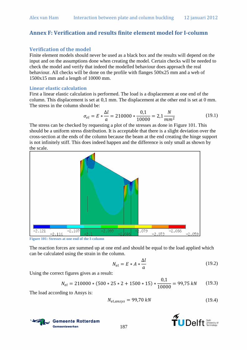
Alex van Ham Interaction between plate and column buckling 12 januari 2012
187
Annex F: Verification and results finite element model for I-column
Verification of the model Finite element models should never be used as a black box and the results will depend on the
input and on the assumptions done when creating the model. Certain checks will be needed to
check the model and verify that indeed the modelled behaviour does approach the real
behaviour. All checks will be done on the profile with flanges 500x25 mm and a web of
1500x15 mm and a length of 10000 mm.
Linear elastic calculation First a linear elastic calculation is performed. The load is a displacement at one end of the
column. This displacement is set at mm. The displacement at the other end is set at 0 mm.
The stress in the column should be:
(19.1)
The stress can be checked by requesting a plot of the stresses as done in Figure 101. This
should be a uniform stress distribution. It is acceptable that there is a slight deviation over the
cross-section at the ends of the column because the beam at the end creating the hinge support
is not infinitely stiff. This does indeed happen and the difference is only small as shown by
the scale.
Figure 101: Stresses at one end of the I-column
The reaction forces are summed up at one end and should be equal to the load applied which
can be calculated using the strain in the column.
(19.2)
Using the correct figures gives as a result:
(19.3)
The load according to Ansys is:
(19.4)

Alex van Ham Interaction between plate and column buckling 12 januari 2012
188
This is equal to the load so the linear elastic calculation is correct. The small difference
(0,05%) can be explained because of the hinge support that is created that is not infinitely
stiff.
Plastic calculation A plastic calculation is a non-linear calculation in physical sense. The result should be a fully
yielded cross-section resulting in a force equal to:
(19.5)
The result in Ansys is:
(19.6)
This is equal to the load so the plastic calculation is correct. The small difference (0,07%) can
again be explained because of the hinge support and the very small increase in stiffness after
yielding.
Theoretical buckling load The theoretical buckling load is calculated for a different configuration because the difference
between the column buckling load and the buckling load according to Chapter 4 is very small
for the given configuration. Therefore the configuration with flanges 150x15 mm and a web
of 1500x15 mm and a length of 4000 mm. The theoretical buckling load according to Chapter
4 is:
(19.7)
The displacement in Ansys is set at 0,1 mm so the stress is equal to the stress in equation
(19.1). An eigenvalue linear buckling analysis is done and a load factor of is the result.
Therefore the critical stress according to Ansys is:
(19.8)
This is approximately equal to the stress as calculated in equation (19.7) so the result is
correct. The slight difference (1,19%) in buckling load is probably due to a slightly different
deflection shape which is not included in the analytical model.

Alex van Ham Interaction between plate and column buckling 12 januari 2012
189
Figure 102: Displacement of I-column for first buckling mode
In Figure 102 the buckling mode is shown for the given geometry. This is indeed the
behaviour that was expected based on Chapter 4. The column has a global deflection and the
web has an additional local deflection with a single half-sine wave. The ratio of the deflection
from the flange to the web is:
(19.9)
The calculated value according to Chapter 4 is:
(19.10)
This difference (11,3%) is explained before because the sensitivity to a different column or
beam length is very large. The calculated value for 4100 mm is 4,02 which is about right.
Mesh refinement The mesh is defined by applying 10 elements in the width of the web. The flanges are divided
in width by 6 elements. There are 40 elements in length direction. A refinement of the mesh
should lead to a result that is similar to the calculation with a coarse mesh. Therefore the
given profile with imperfections according to the buckling load of Chapter 4 is calculated in
FEM with a non-linear calculation. The mesh may be refined but it may also be coarser and
then the same results should be obtained. The mesh is coarsened by a factor 2 and the results
are presented in Figure 103. It does indeed look the same and the maximum load only changes
from to . This is a minor difference (0,13%) so the fine mesh is sufficient
for the analysis and probably the coarse mesh would also be sufficient.

Alex van Ham Interaction between plate and column buckling 12 januari 2012
190
Figure 103: Results using a fine and a coarse mesh
Load step reduced The load step (which is actually a displacement step) is important because it allows the step
by step increase until failure. The load steps should be small enough to allow plastic strains to
develop and second order displacements to occur. Therefore for the given profile the load step
is applied and also a load step of 25% of the original load step is applied. The results are
presented as a load-displacement graph in Figure 104. The lines overlap in the graph so the
difference is negligible. This means that a load step of 0,01 (100 steps) is sufficient for the
analysis.
Figure 104: Results using a large and a small load step (lines overlap)
0,00E+00
1,00E+06
2,00E+06
3,00E+06
4,00E+06
5,00E+06
6,00E+06
0 50 100 150 200 250 300 350
Axia
l fo
rce a
pplie
d [
N]
Displacement out of plane of web [mm]
fine mesh
coarse mesh
0,00E+00
1,00E+06
2,00E+06
3,00E+06
4,00E+06
5,00E+06
6,00E+06
0 50 100 150 200 250 300 350
Axia
l fo
rce a
pplie
d [
N]
Displacement out of plane of web [mm]
load step 0,01
load step 0,0025

Alex van Ham Interaction between plate and column buckling 12 januari 2012
191
Simple checks in FEM There are several fairly simple and fast checks to be able to investigate whether the model is
producing accurate results. The first one is to check whether the maximum stress is indeed
below or equal to the yield stress. Therefore a plot is requested of the Von Mises stress at a
large displacement of:
(19.11)
The Von Mises stress is plotted in Figure 105.
Figure 105: Von Mises stress at large displacement
It is clear that the Von Mises stress is equal to the yield stress in the flanges where the
bending moment is largest. If the stress is slightly over the yield stress, this can be explained
by the very small increase of the Young’s modulus after yielding and by the extrapolation of
the stresses from the integration points in the elements to the edges of the elements.
Another very easy check is to check whether the total reactions are zero at the large
displacement used above. This is given in Table 9. The results are indeed very small so this is
correct.
Reaction force Value [N]
Table 9: Total reactions for all nodes
Also a calculation using a different iteration method for the non-linear calculation is a check
whether the calculations performed are correct. The calculation has been performed using a
full Newton-Raphson procedure and a modified Newton-Raphson procedure and this gave the
same result.

Alex van Ham Interaction between plate and column buckling 12 januari 2012
192
Results All results are here provided. All dimensions are given in mm and N. The first column is the
length of the column. The second column is the result in Ansys using the imperfections in the
NEN-EN1993-1-5 and a single half sine wave in the web. The third column is the result in
Ansys using the imperfections according to the NEN-EN1993-1-5.
Flanges 250x25, web 250x10 a m=1 m=?
1000 3462840 3465020
1250 3366190 3367270
1500 3301410
3304190
1750 3168540 3172550
2000 3101020 3103650
2250 3028460 3030760
2500 2949440 2952700
2750 2863160 2866840
3000 2773080 2776570
3250 2680780 2684790
3500 2583490 2587380
3750 2483150 2487510
4000 2382380 2386870
4250 2284260 2288600
4500 2190170 2194140
4750 2095090 2098990
5000 2000340 2004050
5250 1909260 1912180
5500 1823890 1826930
5750 1742940 1744940
6000 1666290 1668670
6250 1592710 1594980
6500 1521830 1524080
6750 1456430 1458430
7000 1393170 1395020
7250 1333060 1334910
7500 1276110 1277690
7750 1222160 1223580
8000 1169990 1171380
8250 1121590 1122780
8500 1074860 1076090
8750 1031070 1032090
9000 989647 990604
9250 950207 951100
9500 912784 913621
9750 877252 878035
10000 843604 844337
10250 811766 812449
10500 781578 782219
10750 752839 753578
11000 725904 726466
11250 700394 700883
11500 676088 676594
11750 653063 653530
12000 631172 631607
12250 610405 610820
12500 590598 590990
12750 571783 572154
13000 553718 554069
13250 536546 536875
Flanges 250x25,web 250x40 a m=1 m=?
1000 5113720 5126210
1250 5010610 5022490
1500 4801870
4845360
1750 4702680 4702680
2000 4577190 4569580
2250 4415980 4417480
2500 4245680 4246780
2750 4059720 4060170
3000 3860330 3860940
3250 3660490 3659690
3500 3461300 3462700
3750 3261550 3262250
4000 3072010 3071150
4250 2884680 2886900
4500 2706880 2707070
4750 2543070 2543310
5000 2391030 2390490
5250 2247650 2248720
5500 2120790 2120800
5750 2003530 2004030
6000 1896010 1896580
6250 1797160 1796870
6500 1703540 1704260
6750 1617410 1618330
7000 1536870 1537800
7250 1462010 1462850
7500 1391780 1392600
7750 1326250 1327050
8000 1264970 1265490
8250 1207240 1207570
8500 1154490 1153480
8750 1102460 1102770
9000 1054130 1054420

Alex van Ham Interaction between plate and column buckling 12 januari 2012
193
9250 1009370 1009360
9500 966817 966803
9750 927222 927332
10000 889766 889666
10250 854775 854686
10500 821548 821480
10750 790503 790438
11000 761093 761032
11250 733365 733334
11500 707167 707044
11750 682179 682093
12000 658440 658337
12250 636084 635991
12500 614854 614760
12750 594664 594582
13000 575502 575427
13250 557139 557069
Flanges 150x15, web 1500x15 a m=1 m=?
1500 1956500 1956500
1625 1813080 1813080
1750 1686830
1686830
1875 1574710 1574710
2000 1473350 1473350
2125 1379740 1459560
2250 1294290 1367290
2375 1217730 1284080
2500 1147570 1208840
2625 1084510 1140450
2750 1026180 1075710
2875 972880 1018560
3000 923391 964146
3125 875927 915355
3250 832524 867124
3375 792160 823856
3500 754430 783605
3625 719422 745076
3750 685710 706778
3875 653463 673888
4000 624427 641561
4125 596639 613096
4250 570496 585222
4375 545905 559568
4500 522541 535253
4625 501266 512912
4750 481199 492288
4875 461958 471848
5000 444517 453802
5125 427491 436056
5250 411301 422776
5375 395946 406729
5500 381940 392063
5625 368258 377911
5750 355635 364434
5875 343394 351434
6000 332051 339751
6125 321206 328556
6250 310691 317604
6375 300602 307190
6500 291060 297503
6625 281946 288080
6750 273276 277796
6875 265127 269458
7000 257300 261521
7125 249750 253604
7250 242591 246330
7375 235720 239083
7500 229148 232379
7625 222821 225993
Flanges 500x25, web 1500x15 a m=1 m=?
1500 8344780 8344780
2000 8132440
8132440
2500 7963420 8103060
3000 7870250 7976100
3500 7760130 7834410
4000 7618320 7571500
4500 7427000 7374170
5000 7194170 7153920
5500 6928930 7007010
6000 6638780 6737680
6500 6342410 6448920
7000 6049980 6129770
7500 5763030 5834210
8000 5477730 5542910
8500 5197970 5296930
9000 4924670 5024170
9500 4667820 4762760
10000 4426770 4515750
10500 4200420 4272800
11000 3988430 4046110
11500 3787960 3843410
12000 3599320 3647450
12500 3421430 3463370
13000 3254440 3290630
13500 3096620 3124840
14000 2949310 2973720
14500 2810070 2832350
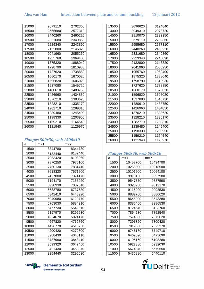
Alex van Ham Interaction between plate and column buckling 12 januari 2012
194
15000 2679110 2702360
15500 2555680 2577310
16000 2440260 2460220
16500 2331680 2349860
17000 2229340 2243890
17500 2132800 2146820
18000 2041960 2055250
18500 1955760 1969400
19000 1875320 1888040
19500 1798790 1810930
20000 1727620 1738850
20500 1660170 1670020
21000 1596820 1606020
21500 1537080 1545720
22000 1480610 1488750
22500 1426960 1434850
23000 1376210 1383620
23500 1328210 1335170
24000 1282710 1289310
24500 1239480 1245400
25000 1198330 1203950
25500 1159210 1164540
26000 1121940 1126970
Flanges 500x30, web 1500x40 a m=1 m=?
1500 8344780 8344780
2000 8132440
8132440
2500 7963420 8103060
3000 7870250 7976100
3500 7760130 7834410
4000 7618320 7571500
4500 7427000 7374170
5000 7194170 7153920
5500 6928930 7007010
6000 6638780 6737680
6500 6342410 6448920
7000 6049980 6129770
7500 5763030 5834210
8000 5477730 5542910
8500 5197970 5296930
9000 4924670 5024170
9500 4667820 4762760
10000 4426770 4515750
10500 4200420 4272800
11000 3988430 4046110
11500 3787960 3843410
12000 3599320 3647450
12500 3421430 3463370
13000 3254440 3290630
13500 3096620 3124840
14000 2949310 2973720
14500 2810070 2832350
15000 2679110 2702360
15500 2555680 2577310
16000 2440260 2460220
16500 2331680 2349860
17000 2229340 2243890
17500 2132800 2146820
18000 2041960 2055250
18500 1955760 1969400
19000 1875320 1888040
19500 1798790 1810930
20000 1727620 1738850
20500 1660170 1670020
21000 1596820 1606020
21500 1537080 1545720
22000 1480610 1488750
22500 1426960 1434850
23000 1376210 1383620
23500 1328210 1335170
24000 1282710 1289310
24500 1239480 1245400
25000 1198330 1203950
25500 1159210 1164540
26000 1121940 1126970
Flanges 500x40, web 500x10 a m=1 m=?
1500 10453700 10434700
2000 10255000 10218500
2500 10101600 10064100
3000 9913100 9897980
3500 9547570 9537590
4000 9323250 9312170
4500 9115020 9098530
5000 8889700 8880620
5500 8645020 8643380
6000 8386400 8386530
6500 8124540 8123760
7000 7854230 7852540
7500 7574800 7575620
8000 7295820 7300420
8500 7019380 7025270
9000 6746180 6749710
9500 6469020 6475690
10000 6195160 6198280
10500 5927380 5932030
11000 5674870 5679550
11500 5435880 5440110

Alex van Ham Interaction between plate and column buckling 12 januari 2012
195
12000 5206970 5211080
12500 4987200 4991200
13000 4778050 4781960
13500 4576790 4580570
14000 4384230 4387860
14500 4201050 4204520
15000 4026250 4029260
15500 3861150 3863640
16000 3699440 3702240
16500 3550840 3553160
17000 3404510 3407080
17500 3268390 3270410
18000 3139410 3141320
18500 3016220 3017910
19000 2898020 2899730
19500 2786640 2788240
20000 2681750 2683260
20500 2581270 2582690
21000 2486030 2487350
21500 2395690 2396940
22000 2310680 2311850
22500 2229920 2231030
23000 2153200 2154260
23500 2080270 2081240
24000 2011150 2012070
24500 1945360 1946230
25000 1882550 1883380
25500 1822740 1823520
26000 1765600 1766330
Flanges 500x40, web 1000x10 a m=1 m=?
1500 10513100 10755100
2000 10347100 10567700
2500 10330400 10403500
3000 10278700 10252100
3500 10171700 9861280
4000 9619170 9666980
4500 9566990 9389100
5000 9386820 9198500
5500 9022730 8981720
6000 8733400 8709970
6500 8477830 8460390
7000 8278440 8170270
7500 7988130 7898310
8000 7683790 7583740
8500 7368910 7299880
9000 7052250 6988950
9500 6737510 6705980
10000 6430370 6408130
10500 6138040 6128400
11000 5861880 5862010
11500 5601440 5604140
12000 5353810 5359280
12500 5117030 5118610
13000 4891270 4896940
13500 4676870 4684490
14000 4473330 4476890
14500 4278900 4283780
15000 4094940 4100230
15500 3919400 3926190
16000 3754160 3760360
16500 3596730 3601890
17000 3445980 3452590
17500 3305740 3311940
18000 3172280 3177490
18500 3045340 3050260
19000 2924990 2930020
19500 2810800 2815410
20000 2702720 2707400
20500 2600240 2604770
21000 2503280 2507380
21500 2411420 2415340
22000 2325140 2328860
22500 2243130 2246690
23000 2165310 2168700
23500 2091310 2094560
24000 2021270 2024370
24500 1954670 1957620
25000 1891140 1893730
25500 1830500 1833020
26000 1772740 1775080
Flanges 500x40, web 1000x30 a m=1 m=?
1500 15821900 15797200
2000 15625800 15769100
2500 15435600 15342300
3000 14817700 15011900
3500 14460400 14481100
4000 14047500 14112100
4500 13586500 13608100
5000 13085900 13134200
5500 12534300 12594100
6000 11932600 12019000
6500 11291900 11393100
7000 10631000 10740300
7500 9973510 10090300
8000 9360720 9459470
8500 8796840 8888920

Alex van Ham Interaction between plate and column buckling 12 januari 2012
196
9000 8278100 8353250
9500 7792470 7862880
10000 7334300 7401190
10500 6918580 6979660
11000 6539460 6595240
11500 6191000 6239970
12000 5867250 5911440
12500 5566120 5607220
13000 5284850 5323010
13500 5023100 5058120
14000 4776610 4808610
14500 4545980 4575090
15000 4331040 4357440
15500 4128270 4152780
16000 3939320 3960970
16500 3761560 3781010
17000 3594240 3612240
17500 3437150 3453830
18000 3289400 3304620
18500 3149290 3163750
19000 3018350 3031020
19500 2895090 2907910
20000 2778740 2790260
20500 2669580 2680750
21000 2567060 2576850
21500 2470070 2479660
22000 2378840 2387730
22500 2292360 2300780
23000 2210530 2218600
23500 2132820 2140440
24000 2059470 2066590
24500 1989850 1996540
25000 1923700 1929950
25500 1860750 1866620
26000 1800820 1806370
Flanges 500x50, web 1500x5 a m=1 m=?
1500 12456200 12456200
2000 12279000 12279000
2500 11650200 11808000
3000 11367600 11628600
3500 11128600 4230240
4000 10910500 10941300
4500 10683500 10691900
5000 10441800 10433100
5500 10157500 10159300
6000 9880420 9879960
6500 9606380 9596230
7000 9295650 9299710
7500 9007150 9009150
8000 1266170 8717220
8500 8419980 8429380
9000 3598960 8122820
9500 7806850 7815670
10000 7501090 7515160
10500 7199790 7215770
11000 6939280 6927900
11500 3222200 6645040
12000 3559610 6380730
12500 2291980 6122820
13000 1834420 5876260
13500 2012480 5632570
14000 2582670 5402830
14500 3596770 5183970
15000 2123310 4977020
15500 1900430 4775310
16000 1870020 4581250
16500 1838170 4399540
17000 4224900 4220530
17500 849648 4056230
18000 3902560 3897350
18500 3745960 3745770
19000 1667700 3602160
19500 801563 3465920
20000 1859650 3336090
20500 1693210 3212410
21000 1989970 3095060
21500 1726970 2983580
22000 2878930 2878580
22500 2779540 2779840
23000 1993190 2684690
23500 1930240 2594540
24000 2508200 2508720
24500 2426430 2427100
25000 2348510 2349200
25500 2274030 2274670
26000 2203240 2203950
Flanges 500x50, web 1500x15 a m=1 m=?
1500 14277300 14277300
2000 14034000 14034000
2500 13930900 14183500
3000 13680000 13941700
3500 13408100 13530600
4000 13243700 13072100
4500 13010300 12856000
5000 12700100 12609900
5500 12325100 12196600

Alex van Ham Interaction between plate and column buckling 12 januari 2012
197
6000 11905600 11838600
6500 11461700 11454300
7000 11009300 10912900
7500 10554300 10499400
8000 10104100 10080600
8500 9649640 9676660
9000 9199730 9253270
9500 8759150 8833810
10000 8337230 8417680
10500 7941400 8016050
11000 7568200 7632720
11500 7214750 7263930
12000 6879050 6927750
12500 6561620 6608620
13000 6259830 6302320
13500 5974230 6002340
14000 5703910 5730820
14500 5449080 5472390
15000 5205510 5234110
15500 4978010 5004010
16000 4760650 4785520
16500 4554450 4578770
17000 4362610 4382010
17500 4180390 4197380
18000 4007870 4023720
18500 3844420 3861720
19000 3689980 3706610
19500 3543840 3559610
20000 3405840 3420630
20500 3275230 3288230
21000 3151860 3163810
21500 3035320 3046540
22000 2925680 2936260
22500 2821550 2831740
23000 2722570 2732400
23500 2628990 2638190
24000 2540250 2548860
24500 2455940 2463760
25000 2375340 2382740
25500 2298700 2305710
26000 2225620 2232320
Flanges 500x50, web 1500x10 a m=1 m=?
1500 13087400 13087400
2000 12846700 12846700
2500 12681500 12819200
3000 12460500 12554900
3500 12051200 12264800
4000 11865000 11827500
4500 11657600 11602200
5000 11410000 11353300
5500 11131500 11029200
6000 10860300 10716900
6500 10336500 10393600
7000 10023900 9985030
7500 9700560 9645960
8000 9371510 9310940
8500 9022550 8990130
9000 8667050 8634980
9500 8304550 8282380
10000 7956740 7940110
10500 7619020 7597490
11000 7302275 7268250
11500 6957900 6949040
12000 6663150 6652130
12500 6376670 6365460
13000 6093480 6090800
13500 5826780 5820470
14000 5573480 5570660
14500 5332570 5333280
15000 5105690 5113720
15500 4884110 4897540
16000 4680950 4693220
16500 4482480 4496850
17000 4298440 4309760
17500 4123500 4133370
18000 3956450 3967130
18500 3798270 3810330
19000 3648500 3660300
19500 3506720 3518480
20000 3372350 3383590
20500 3244730 3254740
21000 3123970 3133340
21500 3010210 3018940
22000 2902690 2910960
22500 2800450 2808690
23000 2703280 2711240
23500 2611500 2618910
24000 2524140 2531060
24500 2441060 2447240
25000 2361810 2367670
25500 2286130 2291680
26000 2214310 2219480
Flanges 500x50, web 1500x20 a m=1 m=?
1500 15759000 15759000
2000 15517400 15517400
2500 15419800 15663100

Alex van Ham Interaction between plate and column buckling 12 januari 2012
198
3000 15210000 15417100
3500 15094200 15270800
4000 14869200 14633700
4500 14531400 14361400
5000 14085700 14007700
5500 13564600 13566500
6000 13003300 13093500
6500 12415800 12556300
7000 11833400 11879300
7500 11263400 11327400
8000 10711800 10784100
8500 10176700 10275300
9000 9654920 9760060
9500 9151670 9259780
10000 8674080 8752280
10500 8233380 8330840
11000 7820930 7904950
11500 7434440 7505220
12000 7072200 7136620
12500 6729330 6789340
13000 6406690 6461100
13500 6103220 6145600
14000 5817390 5854770
14500 5547870 5583260
15000 5293980 5330490
15500 5055610 5088710
16000 4829850 4861390
16500 4616730 4646690
17000 4417160 4441950
17500 4228930 4252020
18000 4051270 4072930
18500 3883410 3905080
19000 3725160 3745450
19500 3575720 3594730
20000 3434790 3452640
20500 3301620 3317500
21000 3175540 3190320
21500 3057010 3070930
22000 2945550 2958650
22500 2839610 2852260
23000 2739240 2751290
23500 2644110 2655380
24000 2554180 2564740
24500 2468660 2478300
25000 2387110 2396240
25500 2309600 2318230
26000 2235750 2244010
Flanges 500x50, web 1500x25 a m=1 m=?
1500 17619800 17619800
2000 17561900 17561900
2500 17189800 17481000
3000 17130400 17216000
3500 16909900 17033100
4000 16527000 16844900
4500 16023800 15847800
5000 15416300 15348000
5500 14741400 14839500
6000 14031000 14197500
6500 13309300 13505400
7000 12594300 12720200
7500 11907000 12043200
8000 11259500 11388400
8500 10645800 10782700
9000 10057600 10189400
9500 9493460 9624110
10000 8968210 9069290
10500 8486900 8584240
11000 8040230 8133240
11500 7624460 7710170
12000 7237010 7316360
12500 6874250 6946520
13000 6533000 6598880
13500 6213990 6266790
14000 5914450 5963940
14500 5633830 5676850
15000 5369780 5413900
15500 5122770 5162520
16000 4889340 4926910
16500 4670180 4705300
17000 4464020 4494110
17500 4270560 4298740
18000 4088730 4115050
18500 3916980 3942380
19000 3755530 3778760
19500 3602470 3624540
20000 3459170 3478970
20500 3323290 3341850
21000 3196200 3213210
21500 3076040 3092410
22000 2962960 2978360
22500 2855560 2870430
23000 2753960 2768060
23500 2657520 2670790
24000 2566570 2578970
24500 2480030 2491320
25000 2397740 2408480
25500 2319470 2329650
26000 2244940 2254540

Alex van Ham Interaction between plate and column buckling 12 januari 2012
199
Flanges 500x50, web 1500x30 a m=1 m=?
1500 19741400 19741400
2000 19483600 19483600
2500 19189100 19171800
3000 18972700 19039500
3500 18584700 18752000
4000 18056900 18565000
4500 17416700 18019400
5000 16669900 17315600
5500 15863300 16016900
6000 15013200 15230500
6500 14148500 14395600
7000 13305200 13493300
7500 12505000 12695500
8000 11759600 11936100
8500 11068100 11238900
9000 10417100 10574100
9500 9798380 9949440
10000 9228130 9351610
10500 8708960 8824300
11000 8232870 8340710
11500 7791300 7890490
12000 7381370 7472320
12500 6999540 7082270
13000 6644850 6718450
13500 6310510 6372590
14000 5999380 6056350
14500 5708890 5759440
15000 5435670 5487250
15500 5181410 5227030
16000 4941690 4984470
16500 4717200 4756840
17000 4506430 4539780
17500 4307380 4339680
18000 4121750 4149090
18500 3945310 3973260
19000 3779900 3805920
19500 3625350 3649640
20000 3479480 3502680
20500 3343310 3363750
21000 3214790 3234120
21500 3093380 3111850
22000 2979070 2995350
22500 2870400 2886690
23000 2767320 2783090
23500 2670260 2685130
24000 2578260 2592270
24500 2490900 2503670
25000 2408030 2420110
25500 2329110 2340470
26000 2253880 2264640
Flanges 500x50, web 1500x35 a m=1 m=?
1500 20888800 20888800
2000 21374400 21374400
2500 21299300 21185700
3000 20683000 20826900
3500 20170300 20415200
4000 19527100 20182400
4500 18757200 19470100
5000 17873600 18607000
5500 16927300 17139300
6000 15919200 16200900
6500 14900100 15204800
7000 13930200 14175000
7500 13037600 13263200
8000 12212500 12416000
8500 11446000 11645900
9000 10728100 10913600
9500 10062200 10230800
10000 9460740 9603190
10500 8908180 9038460
11000 8403620 8524820
11500 7939570 8050930
12000 7509890 7611500
12500 7111460 7204130
13000 6741850 6825130
13500 6397130 6467170
14000 6076370 6139160
14500 5776210 5833620
15000 5495520 5552590
15500 5234340 5285400
16000 4989440 5035120
16500 4756980 4800470
17000 4542860 4576390
17500 4337980 4371520
18000 4147200 4179710
18500 3970170 3999410
19000 3801980 3831470
19500 3647050 3672380
20000 3499520 3525180
20500 3362200 3383760
21000 3232780 3252950
21500 3109210 3129480
22000 2993650 3011750
22500 2884470 2902020
23000 2780660 2797860
23500 2682800 2699000
24000 2590140 2605280

Alex van Ham Interaction between plate and column buckling 12 januari 2012
200
24500 2502050 2515770
25000 2418520 2431210
25500 2338910 2351000
26000 2263120 2274570
Flanges 500x50, web 1500x40 a m=1 m=?
1500 22989400 22989400
2000 23420500 23420500
2500 22837200 22933800
3000 22344000 22560400
3500 21731000 22028000
4000 20974000 21717800
4500 20057000 20856900
5000 19034000 19826400
5500 17908100 18202700
6000 16715600 17077000
6500 15532000 15914400
7000 14480900 14750200
7500 13490400 13749300
8000 12601000 12828100
8500 11754100 11996700
9000 10994500 11200800
9500 10295400 10487400
10000 9666890 9823600
10500 9087300 9232970
11000 8559440 8691820
11500 8074540 8197020
12000 7626710 7738630
12500 7214200 7316010
13000 6831480 6922920
13500 6477380 6553340
14000 6146260 6214600
14500 5838940 5899040
15000 5551560 5611510
15500 5284630 5333200
16000 5030050 5079320
16500 4791020 4838050
17000 4572380 4613830
17500 4366140 4401570
18000 4173130 4209390
18500 3994400 4025610
19000 3824690 3856480
19500 3668300 3695690
20000 3519580 3546530
20500 3380620 3404100
21000 3249880 3271290
21500 3125270 3146790
22000 3008860 3028830
22500 2898820 2917670
23000 2794820 2812500
23500 2695980 2713030
24000 2602330 2618510
24500 2513620 2528350
25000 2429190 2442930
25500 2349110 2361990
26000 2272800 2285170
Flanges 500x50, web 1500x45 a m=1 m=?
1500 25402100 25402100
2000 25321600 25321600
2500 24562400 24929500
3000 23973500 24247000
3500 23255100 23608500
4000 22366300 23194000
4500 21322300 22181000
5000 20094500 20982400
5500 18769200 19154900
6000 17383200 17837200
6500 16101900 16538700
7000 14961200 15255700
7500 13896500 14175400
8000 12922300 13175800
8500 12022400 12279000
9000 11229500 11453900
9500 10507100 10710600
10000 9847770 10028500
10500 9248190 9410050
11000 8702270 8847650
11500 8198970 8331620
12000 7736920 7857580
12500 7311560 7417890
13000 6916920 7011990
13500 6553550 6630570
14000 6214180 6281500
14500 5897170 5961400
15000 5598380 5661160
15500 5326940 5379240
16000 5065940 5118180
16500 4824820 4873710
17000 4603540 4647460
17500 4393890 4437280
18000 4200090 4237780
18500 4018850 4053460
19000 3849160 3880980
19500 3690020 3720350
20000 3541330 3567660
20500 3399370 3425410
21000 3267570 3290370
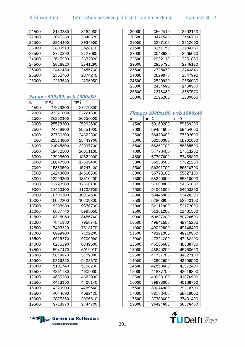
Alex van Ham Interaction between plate and column buckling 12 januari 2012
201
21500 3143330 3164980
22000 3025160 3046520
22500 2914300 2934900
23000 2809510 2828110
23500 2710390 2727080
24000 2615930 2632020
24500 2526520 2541290
25000 2441430 2455730
25500 2360760 2374270
26000 2283680 2296950
Flanges 500x50, web 1500x50 a m=1 m=?
1500 27279800 27279800
2000 27221600 27221600
2500 26302900 26656000
3000 25578300 25902600
3500 24748900 25151900
4000 23730200 24623300
4500 22514800 23449700
5000 21045800 22037700
5500 19480500 20011100
6000 17995600 18522900
6500 16647300 17089400
7000 15383500 15747400
7500 14243800 14560500
8000 13209800 13510200
8500 12290500 12558100
9000 11460900 11703700
9500 10700200 10914500
10000 10022200 10209300
10500 9398980 9576730
11000 8837740 8993050
11500 8315050 8456760
12000 7841880 7968740
12500 7403320 7518170
13000 6999900 7102200
13500 6625270 6700990
14000 6275190 6349500
14500 5947470 6019910
15000 5648870 5709800
15500 5366220 5423370
16000 5101740 5158230
16500 4861130 4909000
17000 4635380 4683930
17500 4423350 4468140
18000 4229900 4269660
18500 4044690 4082420
19000 3875360 3906610
19500 3713570 3744730
20000 3562410 3592110
20500 3421540 3446780
21000 3287160 3312600
21500 3161750 3184760
22000 3043630 3065060
22500 2932110 2951880
23000 2825730 2845150
23500 2725070 2743840
24000 2629970 2647990
24500 2539930 2556030
25000 2454590 2469350
25500 2373330 2387570
26000 2296200 2309650
Flanges 1000x100, web 1500x40 a m=1 m=?
1500 59169200 59169200
2000 59454600 59454600
2500 58423400 57592600
3000 58286300 58761000
3500 58252700 58385500
4000 57778400 57813200
4500 57307600 57459800
5000 56833500 57021200
5500 56301700 56320700
6000 55773100 55827100
6500 55229000 55310000
7000 54663000 54551600
7500 54061000 54003200
8000 53445900 53420200
8500 52803900 52843100
9000 52111900 52172000
9500 51381200 51481500
10000 50627200 50726600
10500 49841500 49945200
11000 49032800 49148400
11500 48221300 48310800
12000 47394200 47482400
12500 46536600 46638700
13000 45649200 45768600
13500 44737700 44827100
14000 43802600 43909500
14500 42850600 42972400
15000 41887700 42019300
15500 40938100 41076900
16000 39993000 40138700
16500 39074900 39218700
17000 38188400 38319000
17500 37303600 37431400
18000 36434600 36576400

Alex van Ham Interaction between plate and column buckling 12 januari 2012
202
18500 35570700 35692500
19000 34715500 34835800
19500 33871600 33988500
20000 33045000 33158900
20500 32232300 32336200
21000 31445900 31546600
21500 30690600 30788500
22000 29960500 30055500
22500 29255300 29347200
23000 28571900 28659700
23500 27906900 27992700
24000 27256700 27339600
24500 26630200 26711600
25000 26018500 26097600
25500 25415400 25495800
26000 24833300 24908400

Alex van Ham Interaction between plate and column buckling 12 januari 2012
203
Annex G: Analytical calculation of I-beam under uniform bending moment without rotational restraint
Stability of a welded I-beam under uniform bending moment A welded I-beam can also lose stability under a uniform bending moment. Local buckling
may occur in the form of multiple half sine waves in the web. In that case the flanges are stiff
enough to support the web and only a loss of stability of the web occurs. Also lateral-torsional
buckling may occur which is a lateral deflection and a torsional rotation of the beam. The
flanges are not stiff enough to support the web. This means that the girder as a whole will
buckle. Also an interaction form may occur which may be unfavourable for the girder.
Especially for fatigue loaded structures and for serviceability limit state it is important to have
a proper estimate of the buckling load of the girder as explained before for the case of uniform
compression.
a
Mx
y
v
uM
θ
z
y
w1
tw
b
hf
tf
w3
w2
Figure 106: Description of situation for uniform bending moment of welded I-beam
Initial deflection as a sum of lateral-torsional and plate buckling behaviour The deformation shape of the beam may be described in the following way. For the global
behaviour a series of sines is used and for the local behaviour a series of sines multiplied by a
series of sines in transverse direction is used. In contradiction to the case of uniform
compression also a series of sines as rotation is used. These deformations are the ones of the
individual buckling shapes of the lateral-torsional and the local behaviour. The deformation of
the web ( ) is a summation of the local and the global behaviour. The deformation of the top
flange ( ) is described by the global behaviour. The behaviour of the bottom flange ( ) is
also described by the global behaviour. At and the web and the flange have the
same deformation for all so compatibility between the web and the flange is ensured.

Alex van Ham Interaction between plate and column buckling 12 januari 2012
204
The behaviour of the web is described by:
(20.1)
The behaviour of the top flange is described by:
(20.2)
The behaviour of the bottom flange is described by:
(20.3)
Total potential energy in the welded I-beam The potential energy in the welded I-beam is a combined calculation. The energy in the I-
beam consists of the energy due to the global and local deflections combined with the energy
due to rotation of the cross-section. All these terms have been calculated before and are
repeated here.
The energy due to the local and global deflection is the same as the total energy in the
structure for the case of uniform compression in the welded I-column with hinged welds. This
is equation (16.29). The triple summations over and are only applicable if . If
that part is equal to 0. The third term of this integral is only applicable for .
(20.4)
The energy due to rotation has already been calculated for the derivation of lateral-torsional
buckling. This is a part of equation (2.23).
(20.5)
The total energy due to deflection and rotation is the sum of equation (20.4) and equation
(20.5).

Alex van Ham Interaction between plate and column buckling 12 januari 2012
205
(20.6)
Virtual work done by the external forces on the web The virtual work done on the web is a more complicated calculation than for the case of
uniform compression because the applied stress is not the same everywhere.
The general expression for the work done is the following:
(20.7)
The stress in a fibre can be described by the following equation.
(20.8)
Integration over is just a multiplication of the equation by the thickness of the web ( ).
(20.9)
First the derivative of with respect to needs to be determined.
(20.10)
Now the derivative needs to be squared.

Alex van Ham Interaction between plate and column buckling 12 januari 2012
206
(20.11)
Equation (20.9) can now be evaluated using equation (20.11). Equation (20.9) contains six
terms which are evaluated separately for clarification.
The first term is equal to zero.
(20.12)
The second term is only valid if and if .
(20.13)
The third term is equal to zero.

Alex van Ham Interaction between plate and column buckling 12 januari 2012
207
(20.14)
The fourth term is only applicable if and if .
(20.15)
The fifth term is only valid if .
(20.16)
The sixth term is only valid if and if .
(20.17)
Therefore the virtual work done on the web can be calculated. All the terms in the total
equation are still related to the conditions that are stated before for when they are valid.

Alex van Ham Interaction between plate and column buckling 12 januari 2012
208
(20.18)
Virtual work done by the external forces on the flange The general expression for the work done on the top flange is the following:
(20.19)
The stress in the top flange is the following:
(20.20)
Integration over and is just a multiplication of the equation by the area of the flange.
(20.21)
First the derivative of with respect to needs to be determined.
(20.22)
Now the derivative needs to be squared.
(20.23)
This allows the calculation of where the third term is only applicable if .

Alex van Ham Interaction between plate and column buckling 12 januari 2012
209
(20.24)
The general expression for the work done on the bottom flange is the following:
(20.25)
The stress in the bottom flange is the following:
(20.26)
Integration over and is just a multiplication of the equation by the area of the flange.
(20.27)
First the derivative of with respect to needs to be determined.
(20.28)
Now the derivative needs to be squared.
(20.29)
This allows the calculation of where the third term is only applicable if .
(20.30)
Now the total virtual work done on the flanges can be calculated. That is the sum of
(equation (20.24)) and (equation (20.30)).

Alex van Ham Interaction between plate and column buckling 12 januari 2012
210
(20.31)
Virtual work done by the external forces on the welded I-beam The results for the virtual work done on the web (equation (20.18)) and on both flanges
(equation (20.31)) can be combined and results in the total virtual work done on the welded I-
beam. All the previously mentioned conditions for all the specific terms are still valid but not
repeated here.
(20.32)
Determine equilibrium condition The limit state where the construction is just stable is the point where the total potential
energy in the beam is equal to the virtual work done by the external forces. This equation is
but is not shown here because of the length of the equation. The equation
is still depending on , and . Now it is clear that only one value of , and should
be used. However, there are multiple values of s that may be in the solution. The accuracy of
the solution decreases when the ratio increases. (Timoshenko & Gere, 1963, pp. 354-355)
This calculation is also made for relatively long girders so therefore a check should be
performed to show that the calculation is sufficiently accurate by increasing the maximum
value of by 1 and the difference should be sufficiently small.
The minimum of is obtained when the derivatives are taken with respect to , and and equated to zero.

Alex van Ham Interaction between plate and column buckling 12 januari 2012
211
(20.33)
(20.34)
(20.35)
The derivatives may be written in matrix form. All equations are only valid for a single
.

Alex van Ham Interaction between plate and column buckling 12 januari 2012
212

Alex van Ham Interaction between plate and column buckling 12 januari 2012
213
Verification of the result To verify whether calculations have been done correctly, only the lateral-torsional buckling
behaviour is checked which means that ( ).
(20.36)
This is the same as the matrix for lateral-torsional buckling (equation (2.34)). Therefore this is
correct.
The verification for plate buckling ( and ) can be done by calculating the
theoretical buckling factor of for a bending moment. This has been done and this is
correct.

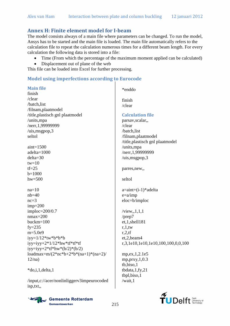
Alex van Ham Interaction between plate and column buckling 12 januari 2012
215
Annex H: Finite element model for I-beam The model consists always of a main file where parameters can be changed. To run the model,
Ansys has to be started and the main file is loaded. The main file automatically refers to the
calculation file to repeat the calculation numerous times for a different beam length. For every
calculation the following data is stored into a file:
Time (From which the percentage of the maximum moment applied can be calculated)
Displacement out of plane of the web
This file can be loaded into Excel for further processing.
Model using imperfections according to Eurocode
Main file finish
/clear
/batch,list
/filnam,plaatmodel
/title,plastisch gnl plaatmodel
/units,mpa
/nerr,1,99999999
/uis,msgpop,3
seltol
aint=1500
adelta=1000
delta=30
tw=10
tf=25
b=1000
hw=500
na=10
nb=40
nc=3
imp=200
imploc=200/0.7
nmax=200
buckm=100
fy=235
m=5.0e9
iyy=1/12*tw*b*b*b
iyy=iyy+2*1/12*hw*tf*tf*tf
iyy=iyy+2*tf*hw*(b/2)*(b/2)
loadmax=m/(2*nc*b+2*b*(na+1)*(na+2)/
12/na)
*do,i,1,delta,1
/input,c://acer/nonlinliggerv3impeurocoded
isp,txt,,
*enddo
finish
/clear
Calculation file parsav,scalar,,
/clear
/batch,list
/filnam,plaatmodel
/title,plastisch gnl plaatmodel
/units,mpa
/nerr,1,99999999
/uis,msgpop,3
parres,new,,
seltol
a=aint+(i-1)*adelta
e=a/imp
eloc=b/imploc
/view,,1,1,1
/prep7
et,1,shell181
r,1,tw
r,2,tf
et,2,beam4
r,3,1e10,1e10,1e10,100,100,0,0,100
mp,ex,1,2.1e5
mp,prxy,1,0.3
tb,biso,1
tbdata,1,fy,21
tbpl,biso,1
/wait,1

Alex van Ham Interaction between plate and column buckling 12 januari 2012
216
k,,0,0,0
k,,0,0,hw/2
k,,0,0,-hw/2
k,,b,0,0
k,,b,0,hw/2
k,,b,0,-hw/2
k,,0,a,0
k,,0,a,hw/2
k,,0,a,-hw/2
k,,b,a,0
k,,b,a,hw/2
k,,b,a,-hw/2
kplot
mshape,0
real,1
a,1,4,10,7
real,1
lsel,s,tan1,x,1
lsel,a,tan1,x,-1
lesize,all,,,na
lsel,s,tan1,y,1
lsel,a,tan1,y,-1
lesize,all,,,nb
asel,s,area,,1,1,1
amesh,all
real,1
nsel,s,loc,x,b/2
nsel,r,loc,y,0
nsel,r,loc,z,0
d,all,ux,0
nsel,s,loc,x,b/2
nsel,r,loc,y,a
nsel,r,loc,z,0
d,all,ux,0
*do,k,1,na+1,1
nsel,s,loc,y,a
nsel,r,loc,x,(k-1)*b/na
d,all,uz,0
d,all,uy,0.1*(2*(k-1)/na-1)
*enddo
*do,k,1,na+1,1
nsel,s,loc,y,0
nsel,r,loc,x,(k-1)*b/na
d,all,uz,0
d,all,uy,-0.1*(2*(k-1)/na-1)
*enddo
nsel,s,loc,x,0
nsel,a,loc,x,b
nsel,r,loc,z,0
d,all,uz,0
allsel
sbctran
nmiddenboven=node(0.5*b,a,0)
save
finish
/solve
antype,static
pstress,on
allsel
sbctran
solve
finish
/post1
plnsol,u,y,0,,
/wait,2
plnsol,epel,y,0,,
finish
/solve
antype,buckle
bucopt,lanb,1
mxpand,1
solve
finish
/post1
set,last
pldisp,1
plnsol,u,z,0,,
/wait,1
finish
/prep7
/inquire,myjobname,jobname
allsel

Alex van Ham Interaction between plate and column buckling 12 januari 2012
217
upgeom,eloc,1,1,'%myjobname(1)%',rst
nsel,s,loc,z,eloc
*get,nmidmid,node,,num,min
save
real,2
a,1,2,8,7
a,1,3,9,7
a,4,5,11,10
a,4,6,12,10
real,3
l,1,2
l,1,3
l,4,5
l,4,6
l,7,8
l,7,9
l,10,11
l,10,12
l,1,4
l,7,10
real,2
lsel,s,tan1,y,1
lsel,a,tan1,y,-1
lesize,all,,,nb
lsel,s,tan1,z,1
lsel,a,tan1,z,-1
lesize,all,,,nc
real,2
asel,s,area,,2,5,1
amesh,all
real,3
lsel,s,tan1,z,1
lsel,a,tan1,z,-1
lsel,a,tan1,x,1
lsel,a,tan1,x,-1
lmesh,all
nsel,s,loc,y,0
nsel,a,loc,y,a
nsel,invert
ddele,all,uz
nsel,all
fdele,all
ddele,all,uy
nsel,s,loc,x,b/2
nsel,r,loc,y,a/2
d,all,uy,0
*do,k,1,na+1,1
nsel,s,loc,y,a
nsel,r,loc,x,(k-1)*b/na
f,all,fy,10000*(2*(k-1)/na-1)
*enddo
*do,k,1,na+1,1
nsel,s,loc,y,0
nsel,r,loc,x,(k-1)*b/na
f,all,fy,-10000*(2*(k-1)/na-1)
*enddo
*do,k,1,nb+1,1
nsel,s,loc,y,0+(k-1)*a/nb
cp,next,roty,all
*enddo
save
finish
/solve
antype,static
pstress,on
allsel
sbctran
solve
finish
/solve
antype,buckle
bucopt,lanb,buckm
mxpand,buckm
solve
finish
/post1
set,last
pldisp,1
plnsol,u,z,0,,
/wait,1
finish
/post26

Alex van Ham Interaction between plate and column buckling 12 januari 2012
218
numvar,200
nsel,s,loc,x,0
nsel,r,loc,y,a/2
*get,nmin,node,0,nxth
*get,ntot,node,,count
nsol,3,nmin,u,z
*do,ndo,2,ntot
*get,nmin,node,nmin,nxth
nsol,196,nmin,u,z
add,3,3,196,,uz_tot
*enddo
*dim,uz_tot,array,buckm
vget,uz_tot(1),3
buckuz=uz_tot(1)
bucktoe=1
*do,j,2,buckm,1
*if,uz_tot(j),gt,buckuz,then
buckuz=uz_tot(j)
bucktoe=j
*else
*endif
*enddo
nsel,all
finish
/solve
antype,buckle
bucopt,lanb,bucktoe
mxpand,bucktoe
solve
finish
/post1
set,last
pldisp,1
plnsol,u,z,0,,
/wait,1
finish
/prep7
/inquire,myjobname,jobname
allsel
upgeom,e,1,bucktoe,'%myjobname(1)%',rs
t
nsel,s,loc,z,e
*get,nmidmid,node,,num,min
nsel,all
cpdele,all
nsel,all
fdele,all
seltol,10
*do,k,1,na+1,1
nsel,s,loc,y,a
nsel,r,loc,x,(k-1)*b/na
f,all,fy,loadmax*(2*(k-1)/na-1)
*enddo
*do,k,1,na+1,1
nsel,s,loc,y,0
nsel,r,loc,x,(k-1)*b/na
f,all,fy,-loadmax*(2*(k-1)/na-1)
*enddo
save
finish
/solve
antype,static
nlgeom,on
outres,all,all
allsel
sbctran
nsubst,nmax,nmax,nmax
kbc,0
solve
save
finish
/post26
numvar,200
allsel
nsol,200,nmiddenboven,u,y,uyneg
filldata,199,,,,-1,0
prod,2,200,199,,uy
nsel,s,loc,y,0
*get,nmin,node,0,nxth
*get,ntot,node,,count
rforce,3,nmin,f,y
*do,ndo,2,ntot
*get,nmin,node,nmin,nxth
rforce,196,nmin,f,y

Alex van Ham Interaction between plate and column buckling 12 januari 2012
219
add,3,3,196,,fy_tot
*enddo
nsol,198,nmidmid,u,z,uz_echt
filldata,197,,,,e,0
add,4,198,197,,uz
save
*del,_p26_export
*dim,_p26_export,table,nmax,2
vget,_p26_export(1,0),1
vget,_p26_export(1,1),3
vget,_p26_export(1,2),4
/output,'blabla','','.',append
*vwrite,'time','uz'
%14c %14c %14c
*vwrite,_p26_export(1,0),_p26_export(1,1
),_p26_export(1,2)
%14.5g %14.5g %14.5g
/output,term
finish
Model using imperfections according to Eurocode using m=1
Main file finish
/clear
/batch,list
/filnam,plaatmodel
/title,plastisch gnl plaatmodel
/units,mpa
/nerr,1,99999999
/uis,msgpop,3
seltol
aint=1500
adelta=500
delta=50
tw=10
tf=50
b=1500
hw=500
na=10
nb=40
nc=3
imp=200
imploc=200/0.7
nmax=200
buckm=250
buckmgl=100
fy=235
m=1.0e10
iyy=1/12*tw*b*b*b
iyy=iyy+2*1/12*hw*tf*tf*tf
iyy=iyy+2*tf*hw*(b/2)*(b/2)
loadmax=m/(2*nc*b+2*b*(na+1)*(na+2)/
12/na)
*do,i,1,delta,1
/input,c://acer/nonlinliggerv3impeurocoded
ispmis1,txt,,
*enddo
finish
/clear
Calculation file parsav,scalar,,
/clear
/batch,list
/filnam,plaatmodel
/title,plastisch gnl plaatmodel
/units,mpa
/nerr,1,99999999
/uis,msgpop,3
seltol
parres,new,,
a=aint+(i-1)*adelta
e=a/imp
eloc=b/imploc
/view,,1,1,1
/prep7
et,1,shell181
r,1,tw
r,2,tf
et,2,beam4
r,3,1e2,1e9,1e9,100,100,0,0,100

Alex van Ham Interaction between plate and column buckling 12 januari 2012
220
mp,ex,1,2.1e5
mp,prxy,1,0.3
tb,biso,1
tbdata,1,fy,21
tbpl,biso,1
/wait,1
k,,0,0,0
k,,0,0,hw/2
k,,0,0,-hw/2
k,,b,0,0
k,,b,0,hw/2
k,,b,0,-hw/2
k,,0,a,0
k,,0,a,hw/2
k,,0,a,-hw/2
k,,b,a,0
k,,b,a,hw/2
k,,b,a,-hw/2
kplot
/wait,1
mshape,0
real,1
a,1,4,10,7
real,1
lsel,s,tan1,x,1
lsel,a,tan1,x,-1
lesize,all,,,na
lsel,s,tan1,y,1
lsel,a,tan1,y,-1
lesize,all,,,nb
asel,s,area,,1,1,1
amesh,all
real,1
nsel,s,loc,x,b/2
nsel,r,loc,y,0
nsel,r,loc,z,0
d,all,ux,0
nsel,s,loc,x,b/2
nsel,r,loc,y,a
nsel,r,loc,z,0
d,all,ux,0
*do,k,1,na+1,1
nsel,s,loc,y,a
nsel,r,loc,x,(k-1)*b/na
d,all,uz,0
d,all,uy,0.1*(2*(k-1)/na-1)
*enddo
*do,k,1,na+1,1
nsel,s,loc,y,0
nsel,r,loc,x,(k-1)*b/na
d,all,uz,0
d,all,uy,-0.1*(2*(k-1)/na-1)
*enddo
nsel,s,loc,x,0
nsel,a,loc,x,b
nsel,r,loc,z,0
d,all,uz,0
allsel
sbctran
nmiddenboven=node(0.5*b,a,0)
save
finish
/solve
antype,static
pstress,on
allsel
sbctran
solve
finish
/post1
plnsol,u,y,0,,
/wait,2
plnsol,epel,y,0,,
finish
/solve
antype,buckle
bucopt,lanb,buckm
mxpand,buckm
solve
finish
/post1

Alex van Ham Interaction between plate and column buckling 12 januari 2012
221
set,last
pldisp,1
plnsol,u,z,0,,
/wait,1
finish
/post26
numvar,200
nsel,all
*get,nmin,node,0,nxth
*get,ntot,node,,count
nsol,3,nmin,u,z
*do,ndo,2,ntot
*get,nmin,node,nmin,nxth
nsol,196,nmin,u,z
add,3,3,196,,uz_tot
*enddo
*dim,uz_tot,array,buckm
vget,uz_tot(1),3
buckuz=uz_tot(1)
bucktoe=1
*do,j,2,buckm,1
*if,uz_tot(j),gt,buckuz,then
buckuz=uz_tot(j)
bucktoe=j
*else
*endif
*enddo
finish
/solve
antype,buckle
bucopt,lanb,bucktoe
mxpand,bucktoe
solve
finish
/post1
set,last
pldisp,1
plnsol,u,z,0,,
/wait,1
finish
/prep7
/inquire,myjobname,jobname
allsel
upgeom,eloc,1,bucktoe,'%myjobname(1)%
',rst
nsel,s,loc,z,eloc
*get,nmidmid,node,,num,min
save
real,2
a,1,2,8,7
a,1,3,9,7
a,4,5,11,10
a,4,6,12,10
real,3
l,1,2
l,1,3
l,4,5
l,4,6
l,7,8
l,7,9
l,10,11
l,10,12
l,1,4
l,7,10
real,2
lsel,s,tan1,y,1
lsel,a,tan1,y,-1
lesize,all,,,nb
lsel,s,tan1,z,1
lsel,a,tan1,z,-1
lesize,all,,,nc
real,2
asel,s,area,,2,5,1
amesh,all
real,3
lsel,s,tan1,z,1
lsel,a,tan1,z,-1
lsel,a,tan1,x,1
lsel,a,tan1,x,-1
lmesh,all
nsel,s,loc,y,0
nsel,a,loc,y,a
nsel,invert
ddele,all,uz
nsel,all

Alex van Ham Interaction between plate and column buckling 12 januari 2012
222
fdele,all
ddele,all,uy
nsel,s,loc,x,b/2
nsel,r,loc,y,a/2
d,all,uy,0
*do,k,1,na+1,1
nsel,s,loc,y,a
nsel,r,loc,x,(k-1)*b/na
f,all,fy,100000*(2*(k-1)/na-1)
*enddo
*do,k,1,na+1,1
nsel,s,loc,y,0
nsel,r,loc,x,(k-1)*b/na
f,all,fy,-100000*(2*(k-1)/na-1)
*enddo
*do,k,1,nb+1,1
nsel,s,loc,y,0+(k-1)*a/nb
cp,next,roty,all
*enddo
save
finish
/solve
antype,static
pstress,on
allsel
sbctran
solve
finish
/solve
antype,buckle
bucopt,lanb,buckmgl
mxpand,buckmgl
solve
finish
/post26
numvar,200
nsel,s,loc,x,0
nsel,r,loc,y,a/2
*get,nmin,node,0,nxth
*get,ntot,node,,count
nsol,3,nmin,u,z
*do,ndo,2,ntot
*get,nmin,node,nmin,nxth
nsol,196,nmin,u,z
add,3,3,196,,uz_tott
*enddo
*dim,uz_tott,array,buckmgl
vget,uz_tott(1),3
buckuz=uz_tott(1)
bucktoegl=1
*do,j,2,buckmgl,1
*if,uz_tott(j),gt,buckuz,then
buckuz=uz_tott(j)
bucktoegl=j
*else
*endif
*enddo
nsel,all
finish
/solve
antype,buckle
bucopt,lanb,bucktoegl
mxpand,bucktoegl
solve
finish
/post1
set,last
pldisp,1
plnsol,u,z,0,,
/wait,1
finish
/prep7
/inquire,myjobname,jobname
allsel
upgeom,e,1,bucktoegl,'%myjobname(1)%',
rst
nsel,s,loc,z,e
*get,nmidmid,node,,num,min
nsel,all
cpdele,all
nsel,all
fdele,all

Alex van Ham Interaction between plate and column buckling 12 januari 2012
223
seltol,10
*do,k,1,na+1,1
nsel,s,loc,y,a
nsel,r,loc,x,(k-1)*b/na
f,all,fy,loadmax*(2*(k-1)/na-1)
*enddo
*do,k,1,na+1,1
nsel,s,loc,y,0
nsel,r,loc,x,(k-1)*b/na
f,all,fy,-loadmax*(2*(k-1)/na-1)
*enddo
save
finish
/solve
antype,static
nlgeom,on
outres,all,all
allsel
sbctran
nsubst,nmax,nmax,nmax
kbc,0
solve
save
finish
/post26
numvar,200
allsel
nsol,200,nmiddenboven,u,y,uyneg
filldata,199,,,,-1,0
prod,2,200,199,,uy
nsel,s,loc,y,0
*get,nmin,node,0,nxth
*get,ntot,node,,count
rforce,3,nmin,f,y
*do,ndo,2,ntot
*get,nmin,node,nmin,nxth
rforce,196,nmin,f,y
add,3,3,196,,fy_tot
*enddo
nsol,198,nmidmid,u,z,uz_echt
filldata,197,,,,e,0
add,4,198,197,,uz
save
*del,_p26_export
*dim,_p26_export,table,nmax,2
vget,_p26_export(1,0),1
vget,_p26_export(1,1),3
vget,_p26_export(1,2),4
/output,'blabla','','.',append
*vwrite,'time','uz'
%14c %14c %14c
*vwrite,_p26_export(1,0),_p26_export(1,1
),_p26_export(1,2)
%14.5g %14.5g %14.5g
/output,term
finish

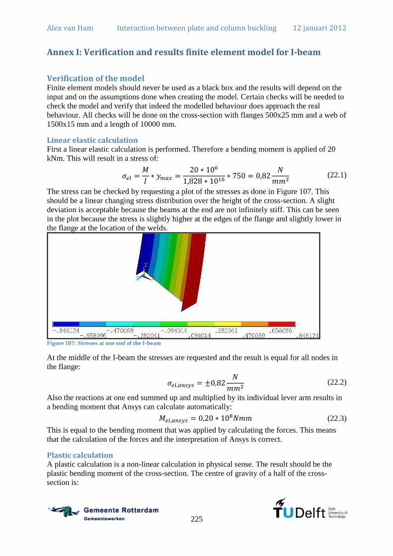
Alex van Ham Interaction between plate and column buckling 12 januari 2012
225
Annex I: Verification and results finite element model for I-beam
Verification of the model Finite element models should never be used as a black box and the results will depend on the
input and on the assumptions done when creating the model. Certain checks will be needed to
check the model and verify that indeed the modelled behaviour does approach the real
behaviour. All checks will be done on the cross-section with flanges 500x25 mm and a web of
1500x15 mm and a length of 10000 mm.
Linear elastic calculation First a linear elastic calculation is performed. Therefore a bending moment is applied of 20
kNm. This will result in a stress of:
(22.1)
The stress can be checked by requesting a plot of the stresses as done in Figure 107. This
should be a linear changing stress distribution over the height of the cross-section. A slight
deviation is acceptable because the beams at the end are not infinitely stiff. This can be seen
in the plot because the stress is slightly higher at the edges of the flange and slightly lower in
the flange at the location of the welds.
Figure 107: Stresses at one end of the I-beam
At the middle of the I-beam the stresses are requested and the result is equal for all nodes in
the flange:
(22.2)
Also the reactions at one end summed up and multiplied by its individual lever arm results in
a bending moment that Ansys can calculate automatically:
(22.3)
This is equal to the bending moment that was applied by calculating the forces. This means
that the calculation of the forces and the interpretation of Ansys is correct.
Plastic calculation A plastic calculation is a non-linear calculation in physical sense. The result should be the
plastic bending moment of the cross-section. The centre of gravity of a half of the cross-
section is:

Alex van Ham Interaction between plate and column buckling 12 januari 2012
226
(22.4)
Applying the correct figures results in:
(22.5)
Therefore the plastic bending moment capacity is:
(22.6)
Applying the correct figures results in:
(22.7)
The bending moment as input in Ansys is and the load factor at collapse is
0,53 so the plastic load is:
(22.8)
This is approximately equal to the plastic bending moment capacity so the plastic analysis is
correct. A smaller load step would approximate the plastic capacity even more.
Mesh refinement The mesh for the I-beam is the same as it is for the I-column. However, the mesh should again
be checked by using a coarser mesh or a finer mesh which should have no significant
influence on the result. The coarser mesh and the fine mesh are applied and the results are
given in Figure 108. Both meshes give approximately the same result and the collapse load
differs 1,09%. This is sufficiently small and would probably be even smaller if the load step
was reduced. The major difference with the I-column is that the post-critical behaviour is not
displayed in this graph as it is a load-controlled analysis.
Figure 108: Results using a fine and a coarse mesh
0,0E+00
5,0E+08
1,0E+09
1,5E+09
2,0E+09
2,5E+09
3,0E+09
3,5E+09
4,0E+09
4,5E+09
5,0E+09
40 50 60 70 80 90 100 110
Bendin
g m
om
ent [N
mm
]
Displacement out of plane of web [mm]
coarse mesh
fine mesh

Alex van Ham Interaction between plate and column buckling 12 januari 2012
227
Load step reduced The load step is also important as explained for the I-column for the development of plastic
strains and second order displacements. However, the load step is also important because the
analysis is load-controlled. Therefore the accuracy is determined by the load step. The load
step for this analysis is set at 0,005 (200 steps) and the reduced load step is set at 0,001 (1000
steps). The results are given in Figure 109.
Figure 109: Results using a large and a small load step
Simple checks in FEM There are several fairly simple and fast checks to be able to investigate whether the model is
producing accurate results. The first one is to check whether the maximum stress is indeed
below or equal to the yield stress. The Von Mises stress is plotted in Figure 105 at the
maximum bending moment.
Figure 110: Von Mises stress at maximum loading
0,00E+00
5,00E+08
1,00E+09
1,50E+09
2,00E+09
2,50E+09
3,00E+09
3,50E+09
4,00E+09
4,50E+09
5,00E+09
40 60 80 100 120
Bendin
g m
om
ent [N
mm
]
Displacement out of plane of web [mm]
load step 0,001
load step 0,005
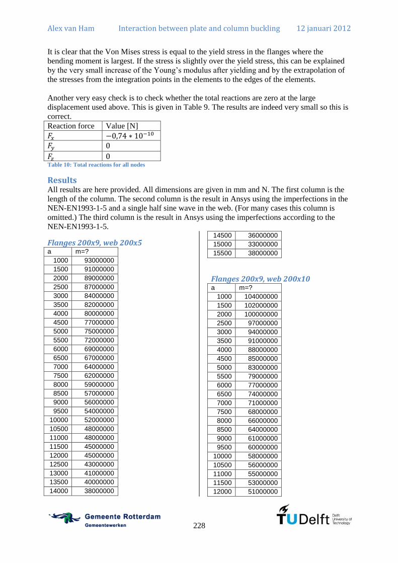
Alex van Ham Interaction between plate and column buckling 12 januari 2012
228
It is clear that the Von Mises stress is equal to the yield stress in the flanges where the
bending moment is largest. If the stress is slightly over the yield stress, this can be explained
by the very small increase of the Young’s modulus after yielding and by the extrapolation of
the stresses from the integration points in the elements to the edges of the elements.
Another very easy check is to check whether the total reactions are zero at the large
displacement used above. This is given in Table 9. The results are indeed very small so this is
correct.
Reaction force Value [N]
Table 10: Total reactions for all nodes
Results All results are here provided. All dimensions are given in mm and N. The first column is the
length of the column. The second column is the result in Ansys using the imperfections in the
NEN-EN1993-1-5 and a single half sine wave in the web. (For many cases this column is
omitted.) The third column is the result in Ansys using the imperfections according to the
NEN-EN1993-1-5.
Flanges 200x9, web 200x5 a m=?
1000 93000000
1500 91000000
2000 89000000
2500 87000000
3000 84000000
3500 82000000
4000 80000000
4500 77000000
5000 75000000
5500 72000000
6000 69000000
6500 67000000
7000 64000000
7500 62000000
8000 59000000
8500 57000000
9000 56000000
9500 54000000
10000 52000000
10500 48000000
11000 48000000
11500 45000000
12000 45000000
12500 43000000
13000 41000000
13500 40000000
14000 38000000
14500 36000000
15000 33000000
15500 38000000
Flanges 200x9, web 200x10 a m=?
1000 104000000
1500 102000000
2000 100000000
2500 97000000
3000 94000000
3500 91000000
4000 88000000
4500 85000000
5000 83000000
5500 79000000
6000 77000000
6500 74000000
7000 71000000
7500 68000000
8000 66000000
8500 64000000
9000 61000000
9500 60000000
10000 58000000
10500 56000000
11000 55000000
11500 53000000
12000 51000000

Alex van Ham Interaction between plate and column buckling 12 januari 2012
229
12500 48000000
13000 48000000
13500 46000000
14000 44000000
14500 43000000
15000 41000000
15500 39000000
Flanges 150x15, web 1500x15 a m=?
1500 1920000000
1750 1815000000
2000 1710000000
2250 1590000000
2500 1575000000
2750 1455000000
3000 1335000000
3250 1230000000
3500 1080000000
3750 990000000
4000 930000000
4250 855000000
4500 795000000
4750 735000000
5000 690000000
5250 645000000
5500 615000000
5750 585000000
6000 555000000
6250 525000000
6500 495000000
6750 480000000
7000 450000000
7250 420000000
7500 405000000
7750 390000000
8000 375000000
8250 360000000
8500 345000000
8750 330000000
Flanges 400x40, web 500x8 a m=?
2000 1935000000
4000 1860000000
6000 1770000000
8000 1680000000
10000 1590000000
12000 1515000000
14000 1425000000
16000 1365000000
18000 1290000000
20000 1245000000
22000 1185000000
24000 1140000000
26000 1080000000
28000 1035000000
30000 1005000000
32000 960000000
34000 945000000
36000 900000000
38000 870000000
40000 810000000
Flanges 400x40, web 500x20 a m=?
2000 2100000000
4000 2025000000
6000 1935000000
8000 1845000000
10000 1770000000
12000 1680000000
14000 1590000000
16000 1515000000
18000 1440000000
20000 1365000000
22000 1290000000
24000 1230000000
26000 1170000000
28000 1125000000
30000 1080000000
32000 1035000000
34000 990000000
36000 960000000
38000 915000000
40000 870000000
Flanges 500x25, web 1000x10 a m=?
1500 3375000000
2500 3325000000
3500 3275000000
4500 3225000000
5500 3150000000
6500 3075000000
7500 3000000000
8500 2900000000
9500 2800000000

Alex van Ham Interaction between plate and column buckling 12 januari 2012
230
10500 2700000000
11500 2600000000
12500 2475000000
13500 2375000000
14500 2250000000
15500 2150000000
16500 2050000000
17500 1950000000
18500 1850000000
19500 1775000000
20500 1675000000
21500 1600000000
22500 1525000000
23500 1450000000
24500 1400000000
25500 1325000000
26500 1275000000
27500 1225000000
28500 1175000000
29500 1125000000
30500 1075000000
Flanges 500x25, web 1500x10 a m=1 m=?
1500 5070000000 5250000000
2500 5220000000 5250000000
3500 5130000000 5070000000
4500 5070000000 5010000000
5500 4950000000 4890000000
6500 4800000000 4800000000
7500 4650000000 4680000000
8500 4500000000 4500000000
9500 4320000000 4320000000
10500 4140000000 4140000000
11500 3930000000 3960000000
12500 3720000000 3780000000
13500 3540000000 3600000000
14500 3330000000 3390000000
15500 3150000000 3210000000
16500 3000000000 3030000000
17500 2820000000 2880000000
18500 2670000000 2730000000
19500 2520000000 2580000000
20500 2370000000 2430000000
21500 2250000000 2280000000
22500 2130000000 2160000000
23500 2010000000 2070000000
24500 1920000000 1950000000
25500 1830000000 1860000000
26500 1740000000 1770000000
27500 1650000000 1680000000
28500 1590000000 1620000000
29500 1500000000 1530000000
30500 1440000000 1470000000
Flanges 500x25, web 1500x15 a m=?
1500 5910000000
2500 5940000000
3500 5700000000
4500 5610000000
5500 5460000000
6500 5310000000
7500 5160000000
8500 4950000000
9500 4740000000
10500 4530000000
11500 4290000000
12500 4050000000
13500 3840000000
14500 3600000000
15500 3390000000
16500 3210000000
17500 3030000000
18500 2850000000
19500 2670000000
20500 2520000000
21500 2400000000
22500 2250000000
23500 2130000000
24500 2040000000
25500 1920000000
26500 1830000000
27500 1740000000
28500 1680000000
29500 1590000000
30500 1530000000
Flanges 500x25, web 1500x20 a m=?
1500 6600000000
2500 6640000000
3500 6360000000
4500 6240000000
5500 6040000000
6500 5840000000
7500 5640000000
8500 5400000000
9500 5120000000

Alex van Ham Interaction between plate and column buckling 12 januari 2012
231
10500 4880000000
11500 4600000000
12500 4320000000
13500 4040000000
14500 3800000000
15500 3560000000
16500 3360000000
17500 3160000000
18500 2960000000
19500 2800000000
20500 2640000000
21500 2480000000
22500 2360000000
23500 2200000000
24500 2120000000
25500 2000000000
26500 1920000000
27500 1800000000
28500 1720000000
29500 1640000000
30500 1600000000
Flanges 500x25, web 1500x25 a m=?
1500 7065000000
2500 7290000000
3500 7020000000
4500 6840000000
5500 6615000000
6500 6390000000
7500 6120000000
8500 5805000000
9500 5535000000
10500 5175000000
11500 4860000000
12500 4545000000
13500 4275000000
14500 4005000000
15500 3735000000
16500 3510000000
17500 3285000000
18500 3105000000
19500 2925000000
20500 2745000000
21500 2565000000
22500 2430000000
23500 2295000000
24500 2205000000
25500 2070000000
26500 1980000000
27500 1890000000
28500 1800000000
29500 1755000000
30500 1665000000
Flanges 500x25, web 1500x30 a m=?
1500 7920000000
2500 7965000000
3500 7650000000
4500 7425000000
5500 7200000000
6500 6930000000
7500 6615000000
8500 6255000000
9500 5895000000
10500 5490000000
11500 5175000000
12500 4815000000
13500 4500000000
14500 4185000000
15500 3915000000
16500 3690000000
17500 3465000000
18500 3240000000
19500 3060000000
20500 2880000000
21500 2700000000
22500 2565000000
23500 2430000000
24500 2340000000
25500 2205000000
26500 2115000000
27500 2025000000
28500 1935000000
29500 1845000000
30500 1800000000
Flanges 500x25, web 1500x35 a m=?
1500 8700000000
2500 8600000000
3500 8300000000
4500 8050000000
5500 7750000000
6500 7450000000
7500 7100000000
8500 6650000000
9500 6250000000

Alex van Ham Interaction between plate and column buckling 12 januari 2012
232
10500 5800000000
11500 5450000000
12500 5050000000
13500 4750000000
14500 4400000000
15500 4150000000
16500 3850000000
17500 3650000000
18500 3400000000
19500 3200000000
20500 3050000000
21500 2900000000
22500 2750000000
23500 2600000000
24500 2450000000
25500 2350000000
26500 2250000000
27500 2150000000
28500 2050000000
29500 2000000000
30500 1900000000
Flanges 500x25, web 1500x40 a m=?
1500 9350000000
2500 9240000000
3500 8965000000
4500 8690000000
5500 8305000000
6500 7975000000
7500 7590000000
8500 7040000000
9500 6600000000
10500 6160000000
11500 5720000000
12500 5335000000
13500 5005000000
14500 4675000000
15500 4345000000
16500 4070000000
17500 3850000000
18500 3630000000
19500 3410000000
20500 3245000000
21500 3080000000
22500 2915000000
23500 2805000000
24500 2640000000
25500 2530000000
26500 2420000000
27500 2310000000
28500 2255000000
29500 2145000000
30500 2090000000
Flanges 500x25, web 1500x45 a m=?
1500 10010000000
2500 9900000000
3500 9570000000
4500 9295000000
5500 8910000000
6500 8470000000
7500 8030000000
8500 7480000000
9500 6930000000
10500 6490000000
11500 6050000000
12500 5610000000
13500 5280000000
14500 4950000000
15500 4620000000
16500 4345000000
17500 4125000000
18500 3850000000
19500 3685000000
20500 3465000000
21500 3300000000
22500 3135000000
23500 3025000000
24500 2860000000
25500 2750000000
26500 2640000000
27500 2530000000
28500 2475000000
29500 2365000000
30500 2310000000
Flanges 500x25, web 1500x50 a m=1 m=?
1500 10620000000 10680000000
2500 10380000000 10560000000
3500 10080000000 10200000000
4500 9720000000 9840000000
5500 9240000000 9420000000
6500 8760000000 9000000000
7500 8220000000 8520000000
8500 7620000000 7920000000
9500 7080000000 7320000000

Alex van Ham Interaction between plate and column buckling 12 januari 2012
233
10500 6600000000 6840000000
11500 6180000000 6420000000
12500 5760000000 5940000000
13500 5400000000 5580000000
14500 5100000000 5220000000
15500 4800000000 4920000000
16500 4500000000 4620000000
17500 4260000000 4380000000
18500 4020000000 4140000000
19500 3840000000 3960000000
20500 3660000000 3780000000
21500 3480000000 3600000000
22500 3360000000 3420000000
23500 3240000000 3300000000
24500 3060000000 3120000000
25500 2940000000 3000000000
26500 2820000000 2880000000
27500 2760000000 2820000000
28500 2640000000 2700000000
29500 2580000000 2580000000
30500 2460000000 2520000000
Flanges 500x25, web 2000x10 a m=?
1500 7290000000
2500 7110000000
3500 7110000000
4500 7020000000
5500 6705000000
6500 6480000000
7500 6300000000
8500 6075000000
9500 5895000000
10500 5625000000
11500 5355000000
12500 5085000000
13500 4815000000
14500 4545000000
15500 4320000000
16500 4050000000
17500 3825000000
18500 3600000000
19500 3375000000
20500 3195000000
21500 3015000000
22500 2835000000
23500 2700000000
24500 2520000000
25500 2430000000
26500 2295000000
27500 2160000000
28500 2070000000
29500 1980000000
30500 1890000000
Flanges 500x40, web 1000x10 a m=?
1500 5130000000
3000 5010000000
4500 4890000000
6000 4740000000
7500 4560000000
9000 4380000000
10500 4170000000
12000 3930000000
13500 3720000000
15000 3510000000
16500 3300000000
18000 3090000000
19500 2910000000
21000 2730000000
22500 2550000000
24000 2430000000
25500 2280000000
27000 2160000000
28500 2070000000
30000 1950000000
31500 1890000000
33000 1800000000
34500 1710000000
36000 1650000000
37500 1590000000
39000 1560000000
40500 1500000000
42000 1410000000
43500 1380000000
45000 1290000000
Flanges 500x50, web 1500x20 a m=?
1500 10985000000
3000 10920000000
4500 10400000000
6000 10010000000
7500 9620000000
9000 9100000000
10500 8580000000
12000 8060000000
13500 7475000000

Alex van Ham Interaction between plate and column buckling 12 januari 2012
234
15000 6955000000
16500 6435000000
18000 5980000000
19500 5590000000
21000 5200000000
22500 4810000000
24000 4485000000
25500 4225000000
27000 3965000000
28500 3705000000
30000 3510000000
31500 3380000000
33000 3185000000
34500 3055000000
36000 2925000000
37500 2795000000
39000 2665000000
40500 2535000000
42000 2470000000
43500 2275000000
45000 2210000000

Alex van Ham Interaction between plate and column buckling 12 januari 2012
235
Annex J: Calculation tool

Alex van Ham Interaction between plate and column buckling 12 januari 2012
236

Plooicontrole hoofdliggerlijf conform Eurocode R GIngenieursbureau
Plooicontrole hoofdliggerlijf
Aannames-Buigend moment met druk in bovenflens! (Geometrie evt spiegelen als druk in onderflens is)-Voor SLS worden de boven- en onderflens en de verstijvingen als volledig effectief aangemerkt en dus alleen de deelplaten van het lijf opplooi getoetst.-Voor SLS wordt de spanning niet getoetst in de flenzen.-Geometrie en belasting voor patch loading dient apart te worden ingevoerd.-De spanning en plooi in de fictieve pla(a)t(en) wordt niet gecontroleerd-Verstijvingen zijn als dunwandige strips uitgerekend. Zware verstijvingen zijn dus niet toegestaan.-Eventuele troggen worden alleen op de individuele platen gereduceerd en het globale knikgedrag van de trogplaat als geheel wordt nietmeegenomen omdat dit afhangt van de specifieke geometrie.
Algemene factorenRekenwaarde vloeigrens (let op maximale plaatdikte)
Vloeisterkte materiaal fyd 235N
mm2
Afschuifsterkte materiaal τydfyd
3 τyd 136
N
mm2
Elasticiteitsmodulus Ed 210000N
mm2
Poisson factor ν 0.3
ε
235N
mm2
fyd ε 1.00
η 1.0 fyd 460N
mm2
if
1.2 fyd 460N
mm2
if
η 1.20
GEd
2 1 ν( ) G 80769.23
N
mm2
Partiele factoren
Conform EN 1993-2 Steel bridgesTabel 6.1 (NB)weerstand van doorsneden met betrekking tot het overschrijden van de vloeigrens metinbegrip van lokaal plooien
γM0 1.0
γM1 1.0Weerstand van doorsneden in trek tot aan breuk
Weerstand van verbindingen γM2 1.25
plooi hoofdliggerlijf1 met nen.xmcd pagina 1 van 72
Plooicontrole hoofdliggerlijf conform Eurocode R GIngenieursbureau
Invoer geometrietotale hoogte (bovenkant dekplaat tot onderkant onderflens)
ht 1500 mm
Lijfdikte
tw 8 mm
Breedte onderflens links: Breedte onderflens rechts:
bfoL 400 mm bfoR 400mm
Dikte onderflens links: Dikte onderflens rechts:
tfoL 30 mm tfoR 30 mm
Breedte van de bovenflens (links): Breedte van de bovenflens (rechts):
bfbL 500 mm bfbR 500 mm
Dikte van de bovenflens (links): Dikte van de bovenflens (rechts):
tfbL 40 mm tfbR 40 mm
Breedte verstijving 1: Breedte verstijving 2:
bv1 140 mm bv2 100 mm
Dikte verstijving 1: Dikte verstijving 2:
tv1 14 mm tv2 10 mm
Locatie verstijving 1 (t.o.v. bovenkant dekplaat): Locatie verstijving 2 (t.o.v. bovenkant dekplaat):
hv1 400 mm hv2 700 mm Altijd: hv1 hv2 !
Fictieve bovenplaat: Fictieve onderplaat:Bij 1 verstijving, gebruikverstijving 1!
Oppervlak bovenplaat: Oppervlak onderplaat:
Afic.1 0mm2
Afic.2 0mm2
Eigen traagheidsmoment bovenplaat: Eigen traagheidsmoment onderplaat:
Ific.1 0mm4
Ific.2 0mm4
Locatie hart bovenplaat (t.o.v. bovenkant dekplaat): Locatie hart onderplaat (t.o.v. bovenkant dekplaat):
zfic.1 0mm zfic.2 0mm
Reductiefactor axiale druk bovenplaat: Reductiefactor axiale druk onderplaat:
ρfic.1.a 1 ρfic.2.a 1
Reductiefactor moment bovenplaat:
ρfic.1.m 1
fictief1
Aanwezig? fictief2
Aanwezig? verstijving1
Check Box verstijving2
Check Box
trog1
Aanwezig? trog2
Aanwezig? trog3
Aanwezig? trog4
Aanwezig?
Afic.1 Afic.1 fictief1 1=if
0 otherwise
Ific.1 Ific.1 fictief1 1=if
0 otherwise
Afic.1 0.00 mm2
Ific.1 0.00 mm4
Afic.2 Afic.2 fictief2 1=if
0 otherwise
Ific.2 Ific.2 fictief2 1=if
0 otherwise
Afic.2 0.00 mm2
Ific.2 0.00 mm4
bv1 bv1 verstijving1 1=if
0.001mm otherwise
tv1 tv1 verstijving1 1=if
0.001mm otherwise
bv1 140.00 mm
tv1 14.00 mm
bv2 bv2 verstijving2 1=if
0.001mm otherwise
tv2 tv2 verstijving2 1=if
0.001mm otherwise
bv2 0.00 mm
tv2 0.00 mm
plooi hoofdliggerlijf1 met nen.xmcd pagina 2 van 72

Plooicontrole hoofdliggerlijf conform Eurocode R GIngenieursbureau
Trog 1
Trog 1 boven externe breedte:
bt1.e 300mm
Trog 1 boven binnen breedte:
bt1.i 300mm
Trog 1 boven onderflens trog breedte:
bt1.o 250mm
Trog 1 boven bovenplaat dikte:
tt1.b 14mm
Trog 1 boven lijf trog dikte:
tt1.t 8mm
Trog 1 boven onderflens trog dikte:
tt1.o 8mm
Trog 1 boven hoogte:
ht1.t 250mm
Trog 1 hoogte t.o.v. bovenkant plaat
zt1.bk 100mm
Trog 1 aantal mee te nemen:
nt1.t 3
Bruto oppervlakte trog:
At1 bt1.e bt1.i tt1.b bt1.o tt1.o 2 ht1.t tt1.t nt1.t At1 43200.00 mm2
Bruto statisch moment:
St1 tt1.b bt1.e bt1.i tt1.b
2 bt1.o tt1.o tt1.b ht1.t
tt1.o
2
2 ht1.t tt1.tht1.t
2tt1.b
nt1.t St1 3452400.00 mm3
Bruto zwaartepunt:
zt1St1
At1 zt1 79.92 mm
It1.eigen1
12bt1.e bt1.i tt1.b
3 2 tt1.t ht1.t
3 bt1.o tt1.o
3
nt1.t
It1.steiner tt1.b bt1.e bt1.i tt1.b
2zt1
2
bt1.o tt1.o tt1.b ht1.ttt1.o
2 zt1
2
2 ht1.t tt1.tht1.t
2tt1.b zt1
2
nt1.t
Bruto traagheidsmoment:
It1 It1.eigen It1.steiner It1 451070100.00 mm4
Trog 1 reduceren:
kσ 4
ψ 1
λt1.efyd
kσ
π2
Ed
12 1 ν2
tt1.b
bt1.e
2
plooi hoofdliggerlijf1 met nen.xmcd pagina 3 van 72
Plooicontrole hoofdliggerlijf conform Eurocode R GIngenieursbureau
ρt1.eλt1.e 0.055 3 ψ( )
λt1.e2
λt1.e 0.055 3 ψ( )
λt1.e2
1if
1 otherwise
ρt1.e 1.00
bt1.e.eff ρt1.e bt1.e bt1.e.eff 300.00 mm
λt1.ifyd
kσ
π2
Ed
12 1 ν2
tt1.b
bt1.i
2
ρt1.iλt1.i 0.055 3 ψ( )
λt1.i2
λt1.i 0.055 3 ψ( )
λt1.i2
1if
1 otherwise
ρt1.i 1.00
bt1.i.eff ρt1.i bt1.i bt1.i.eff 300.00 mm
λt1.tfyd
kσ
π2
Ed
12 1 ν2
tt1.t
ht1.t
2
ρt1.tλt1.t 0.055 3 ψ( )
λt1.t2
λt1.t 0.055 3 ψ( )
λt1.t2
1if
1 otherwise
ρt1.t 1.00
ht1.t.eff ρt1.t ht1.t ht1.t.eff 250.00 mm
λt1.ofyd
kσ
π2
Ed
12 1 ν2
tt1.o
bt1.o
2
ρt1.oλt1.o 0.055 3 ψ( )
λt1.o2
λt1.o 0.055 3 ψ( )
λt1.o2
1if
1 otherwise
ρt1.o 1.00
bt1.o.eff ρt1.o bt1.o bt1.o.eff 250.00 mm
Effectieve oppervlakte trog:
At1.eff bt1.e.eff bt1.i.eff tt1.b bt1.o.eff tt1.o 2 ht1.t.eff tt1.t nt1.t At1.eff 43200.00 mm2
Effectief statisch moment:
St1.eff tt1.b bt1.e.eff bt1.i.eff tt1.b
2 bt1.o.eff tt1.o tt1.b ht1.t
tt1.o
2
2 ht1.t.eff tt1.tht1.t
2tt1.b
nt1.t
Effectief zwaartepunt:
zt1.effSt1.eff
At1.eff St1.eff 3452400.00 mm
3
zt1.eff 79.92 mm
It1.eigen.eff1
12bt1.e.eff bt1.i.eff tt1.b
3 2 2 tt1.t
ht1.t.eff
2
3
bt1.o.eff tt1.o3
nt1.t
plooi hoofdliggerlijf1 met nen.xmcd pagina 4 van 72

Plooicontrole hoofdliggerlijf conform Eurocode R GIngenieursbureau
It1.steiner.eff tt1.b bt1.e.eff bt1.i.eff tt1.b
2zt1.eff
2
bt1.o.eff tt1.o tt1.b ht1.ttt1.o
2 zt1.eff
2
2ht1.t.eff
2 tt1.t
ht1.t.eff
4tt1.b zt1.eff
2
2ht1.t.eff
2 tt1.t ht1.t
ht1.t.eff
4 tt1.b zt1.eff
2
nt1.t
Effectief traagheidsmoment:
It1.eff It1.eigen.eff It1.steiner.eff It1.eff 451070100.00 mm4
At1 At1 trog1 1=if
0 otherwise
At1 0.00 mm2
zt1 zt1 trog1 1=if
0 otherwise
zt1 0.00 mm
It1 It1 trog1 1=if
0 otherwise
It1 0.00 mm4
At1.eff At1.eff trog1 1=if
0 otherwise
At1.eff 0.00 mm2
zt1.eff zt1.eff trog1 1=if
0 otherwise
zt1.eff 0.00 mm
It1.eff It1.eff trog1 1=if
0 otherwise
It1.eff 0.00 mm4
Trog 1
Trog 2
Trog 3
Trog 4
plooi hoofdliggerlijf1 met nen.xmcd pagina 5 van 72
Plooicontrole hoofdliggerlijf conform Eurocode R GIngenieursbureau
berekening shear lag effect
Nieuw waardes t.g.v. shear lag (wanneer gewenst):
bfbL mm bfbR mm
bfoL mm bfoR mm
plooi hoofdliggerlijf1 met nen.xmcd pagina 6 van 72

Plooicontrole hoofdliggerlijf conform Eurocode R GIngenieursbureau
Bruto doorsnede eigenschappen
Berekening Bruto doorsnede eigenschappentfbmax tfbL tfbL tfbRif
tfbR otherwise
tfbmax 40.00 mm
tfomax tfoL tfoL tfoRif
tfoR otherwise
tfomax 30.00 mm
Lijfhoogte
hw ht tfbmax tfomax hw 1430.00 mm
Deel lijf 1: h1 hv1 tfbmax h1 360.00 mm
Deel lijf 2: h2 hv2 tfbmax h1 h2 300.00 mm
Deel lijf 3: h3 hw h1 h2 h3 770.00 mm
Oppervlakte bovenflens (links) AfbL bfbL tfbL AfbL 20000 mm2
Oppervlakte bovenflens (rechts) AfbR bfbR tfbR AfbR 20000 mm2
Oppervlakte lijf Aw hw tw Aw 11440 mm2
Oppervlakte flens onder (links) AfoL bfoL tfoL AfoL 12000 mm2
Oppervlakte flens onder (rechts) AfoR bfoR tfoR AfoR 12000 mm2
Oppervlakte lijf langsverstijver 1 (lijf) Av1 bv1 tv1 Av1 1960.00 mm2
Oppervlakte lijf langsverstijver 2 (lijf) Av2 bv2 tv2 Av2 0.00 mm2
Oppervlakte totaal:
Atot AfbL AfbR Aw AfoL AfoR Av1 Av2 Afic.1 Afic.2 At1 At2 At3 At4 Atot 77400 mm2
Statisch moment t.o.v. bovenkant profiel:
S AfbLtfbL
2 AfbR
tfbR
2 Aw tfbmax
hw
2
AfoL httfoL
2
AfoR httfoR
2
Av1 hv1 Av2 hv2 Afic.1 zfic.1 Afic.2 zfic.2 At1 zt1.bk zt1 At2 zt2.bk zt2 At3 zt3.bk zt3 At4 zt4.bk zt4
S 4.586 107
mm3
Afstand zwaartepunt e t.o.v. bkbovenflens
ebS
Atot eb 593 mm
Afstand zwaartepunt e t.o.v. okonderflens
eo ht eb eo 907 mm
Excentriciteit van de onderdelen t.o.v.z
efbL ebtfbL
2 efbL 573 mm
efbR ebtfbR
2 efbR 573 mm
ew eb tfbmaxhw
2 ew 162 mm
efoL eb httfoL
2 efoL 892 mm
efoR eb httfoR
2 efoR 892 mm
ev1 eb hv1 ev1 193 mm
ev2 eb hv2 ev2 107 mm
efic.1 eb zfic.1 efic.1 592.52 mm
efic.2 eb zfic.2 efic.2 592.52 mm
e1 eb e2 eb tfbmax e3 0 mm e4 eo tfomax e5 eo
e1 593 mm e2 553 mm e3 0 mm e4 877 mm e5 907 mm
plooi hoofdliggerlijf1 met nen.xmcd pagina 7 van 72
Plooicontrole hoofdliggerlijf conform Eurocode R GIngenieursbureau
Traagheidsmoment y
Iy.01
12bfbL tfbL
3 bfbR tfbR
3 tw hw
3 bfoL tfoL
3 bfoR tfoR
3
bv1 tv13
bv2 tv23
Ific.1 Ific.2 It1 It2 It3 It4
Iy.c AfbL efbL2
AfbR efbR2
Aw ew2
AfoL efoL2
AfoR efoR2
Av1 ev12
Av2 ev22
Afic.1 efic.12
Afic.2 efic.22
At1 zt1.bk zt1 eb 2 At2 zt2.bk zt2 eb 2 At3 zt3.bk zt3 eb 2 At4 zt4.bk zt4 eb 2
Iy Iy.0 Iy.cIy 3.4559 10
10 mm
4
Statisch moment bovenflens:
Sfb AfbL efbL AfbR efbR Afic.1 efic.1 At1 zt1.bk zt1 eb At2 zt2.bk zt2 eb Sfb 2.2901 107
mm3
Statisch moment onderflens:
Sfo AfoL efoL AfoR efoR Afic.2 efic.2 At3 zt3.bk zt3 eb At4 zt4.bk zt4 eb Sfo 2.1419 107
mm3
Maximaal statisch moment
Aandeel verstijvers:
So Sfo 0.5 eo tfomax 2 tw ev1 0if ev2 0if
Sfo 0.5 eo tfomax 2 tw ev2 Av2 ev2 0if ev1 0if
Sfo 0.5 eo tfomax 2 tw ev1 Av1 ev2 0if ev1 0if
Sfo 0.5 eo tfomax 2 tw ev1 Av1 ev2 Av2 ev2 0if ev1 0if
Sb Sfb 0.5 eb tfbmax 2 tw ev2 0if ev1 0if
Sfb 0.5 eb tfbmax 2 tw ev2 Av2 ev2 0if ev1 0if
Sfb 0.5 eb tfbmax 2 tw ev1 Av1 ev2 0if ev1 0if
Sfb 0.5 eb tfbmax 2 tw ev1 Av1 ev2 Av2 ev2 0if ev1 0if
So 24499343.68 mm3
Sb 24499343.68 mm3
Smax So So Sbif
Sb otherwise
Smax 2.45 107
mm3
Controleer of S.o = S.b!
Als dit niet correct is, dan is de geometrie niet goed ingevoerd.
Bruto doorsnede eigenschappen
plooi hoofdliggerlijf1 met nen.xmcd pagina 8 van 72

Plooicontrole hoofdliggerlijf conform Eurocode R GIngenieursbureau
Berekening gereduceerde doorsnede eigenschappen t.g.v. axiale druk:
a 15000mm
Plate buckling effects due to direct stresses at the ultimate limit state (4)
Reduceren doorsnede flenzen t.g.v. axiale druk
ψ 1.0
Bovenflens links:
kσ.fbL.a 0.43
σcr.p.fbL.a kσ.fbL.aπ
2Ed
12 1 ν2
tfbL
bfbL
2
λp.fbL.afyd
σcr.p.fbL.a
ρloc.fbL.a 1.0 λp.fbL.a 0.748if
λp.fbL.a 0.188
λp.fbL.a2
λp.fbL.a 0.748if
σcr.c.fbL.aπ
2Ed tfbL
2
12 1 ν2
a2
λc.fbL.afyd
σcr.c.fbL.a
Φc.fbL.a 0.5 1 0.21 λc.fbL.a 0.2 λc.fbL.a2
χc.fbL.a1
Φc.fbL.a Φc.fbL.a2
λc.fbL.a2
ξc.fbL.a 1σcr.p.fbL.a
σcr.c.fbL.a1if
0 0σcr.p.fbL.a
σcr.c.fbL.aif
σcr.p.fbL.a
σcr.c.fbL.a0
σcr.p.fbL.a
σcr.c.fbL.a 1if
ξc.fbL.a 1.00
ρc.fbL.a ρloc.fbL.a χc.fbL.a ξc.fbL.a 2 ξc.fbL.a χc.fbL.a ρc.fbL.a 1.00
bfbL.a.eff ρc.fbL.a bfbL bfbL.a.eff 500.00 mm
Bovenflens rechts:
kσ.fbR.a 0.43
σcr.p.fbR.a kσ.fbR.aπ
2Ed
12 1 ν2
tfbR
bfbR
2
λp.fbR.afyd
σcr.p.fbR.a
ρloc.fbR.a 1.0 λp.fbR.a 0.748if
λp.fbR.a 0.188
λp.fbR.a2
λp.fbR.a 0.748if
σcr.c.fbR.aπ
2Ed tfbR
2
12 1 ν2
a2
plooi hoofdliggerlijf1 met nen.xmcd pagina 9 van 72
Plooicontrole hoofdliggerlijf conform Eurocode R GIngenieursbureau
λc.fbR.afyd
σcr.c.fbR.a
Φc.fbR.a 0.5 1 0.21 λc.fbR.a 0.2 λc.fbR.a2
χc.fbR.a1
Φc.fbR.a Φc.fbR.a2
λc.fbR.a2
ξc.fbR.a 1σcr.p.fbR.a
σcr.c.fbR.a1if
0 0σcr.p.fbR.a
σcr.c.fbR.aif
σcr.p.fbR.a
σcr.c.fbR.a0
σcr.p.fbR.a
σcr.c.fbR.a 1if
ξc.fbR.a 1.00
ρc.fbR.a ρloc.fbR.a χc.fbR.a ξc.fbR.a 2 ξc.fbR.a χc.fbR.a ρc.fbR.a 1.00
bfbR.a.eff ρc.fbR.a bfbR bfbR.a.eff 500.00 mm
Onderflens links:
kσ.foL.a 0.43
σcr.p.foL.a kσ.foL.aπ
2Ed
12 1 ν2
tfoL
bfoL
2
λp.foL.afyd
σcr.p.foL.a
ρloc.foL.a 1.0 λp.foL.a 0.748if
λp.foL.a 0.188
λp.foL.a2
λp.foL.a 0.748if
σcr.c.foL.aπ
2Ed tfoL
2
12 1 ν2
a2
λc.foL.afyd
σcr.c.foL.a
Φc.foL.a 0.5 1 0.21 λc.foL.a 0.2 λc.foL.a2
χc.foL.a1
Φc.foL.a Φc.foL.a2
λc.foL.a2
ξc.foL.a 1σcr.p.foL.a
σcr.c.foL.a1if
0 0σcr.p.foL.a
σcr.c.foL.aif
σcr.p.foL.a
σcr.c.foL.a0
σcr.p.foL.a
σcr.c.foL.a 1if
ξc.foL.a 1.00
ρc.foL.a ρloc.foL.a χc.foL.a ξc.foL.a 2 ξc.foL.a χc.foL.a ρc.foL.a 1.00
bfoL.a.eff ρc.foL.a bfoL bfoL.a.eff 400.00 mm
Onderflens rechts:
plooi hoofdliggerlijf1 met nen.xmcd pagina 10 van 72
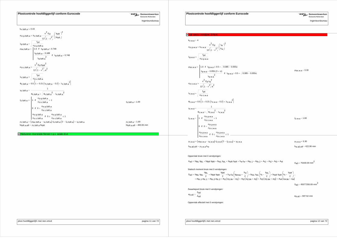
Plooicontrole hoofdliggerlijf conform Eurocode R GIngenieursbureau
kσ.foR.a 0.43
σcr.p.foR.a kσ.foR.aπ
2Ed
12 1 ν2
tfoR
bfoR
2
λp.foR.afyd
σcr.p.foR.a
ρloc.foR.a 1.0 λp.foR.a 0.748if
λp.foR.a 0.188
λp.foR.a2
λp.foR.a 0.748if
σcr.c.foR.aπ
2Ed tfoR
2
12 1 ν2
a2
λc.foR.afyd
σcr.c.foR.a
Φc.foR.a 0.5 1 0.21 λc.foR.a 0.2 λc.foR.a2
χc.foR.a1
Φc.foR.a Φc.foR.a2
λc.foR.a2
ξc.foR.a 1σcr.p.foR.a
σcr.c.foR.a1if
0 0σcr.p.foR.a
σcr.c.foR.aif
σcr.p.foR.a
σcr.c.foR.a0
σcr.p.foR.a
σcr.c.foR.a 1if
ξc.foR.a 1.00
ρc.foR.a ρloc.foR.a χc.foR.a ξc.foR.a 2 ξc.foR.a χc.foR.a ρc.foR.a 1.00
bfoR.a.eff ρc.foR.a bfoR bfoR.a.eff 400.00 mm
Reduceren doorsnede flenzen t.g.v. axiale druk
plooi hoofdliggerlijf1 met nen.xmcd pagina 11 van 72
Plooicontrole hoofdliggerlijf conform Eurocode R GIngenieursbureau
Lijf zonder verstijver (DRUK)
kσ.w.a 4
σcr.p.w.a kσ.w.aπ
2Ed
12 1 ν2
tw
hw
2
λp.w.afyd
σcr.p.w.a
ρloc.w.a 1.0 λp.w.a 0.5 0.085 0.055ψif
λp.w.a 0.055 3 ψ( )
λp.w.a2
λp.w.a 0.5 0.085 0.055ψif
ρloc.w.a 0.30
σcr.c.w.aπ
2Ed tw
2
12 1 ν2
a2
λc.w.afyd
σcr.c.w.a
Φc.w.a 0.5 1 0.21 λc.w.a 0.2 λc.w.a2
χc.w.a1
Φc.w.a Φc.w.a2
λc.w.a2
ξc.w.a 1σcr.p.w.a
σcr.c.w.a1if
0 0σcr.p.w.a
σcr.c.w.aif
σcr.p.w.a
σcr.c.w.a0
σcr.p.w.a
σcr.c.w.a 1if
ξc.w.a 1.00
ρc.w.a ρloc.w.a χc.w.a ξc.w.a 2 ξc.w.a χc.w.a ρc.w.a 0.30
hw.a0.eff ρc.w.a hw hw.a0.eff 422.90 mm
Oppervlak bruto met 0 verstijvingen:
Aa0 bfbL tfbL bfbR tfbR bfoL tfoL bfoR tfoR hw tw Afic.1 Afic.2 At1 At2 At3 At4Aa0 75440.00 mm
2
Statisch moment bruto met 0 verstijvingen:
Sa0 bfbL tfbLtfbL
2 bfbR tfbR
tfbR
2 hw tw tfbmax
hw
2
bfoL tfoL httfoL
2
bfoR tfoR httfoR
2
Afic.1 zfic.1 Afic.2 zfic.2 At1 zt1.bk zt1 At2 zt2.bk zt2 At3 zt3.bk zt3 At4 zt4.bk zt4
Sa0 45077200.00 mm3
Zwaartepunt bruto met 0 verstijvingen:
eb.a0Sa0
Aa0
eb.a0 597.52 mm
Oppervlak effectief met 0 verstijvingen:
plooi hoofdliggerlijf1 met nen.xmcd pagina 12 van 72

Plooicontrole hoofdliggerlijf conform Eurocode R GIngenieursbureau
Aa0.eff bfbL.a.eff tfbL bfbR.a.eff tfbR bfoL.a.eff tfoL bfoR.a.eff tfoR hw.a0.eff tw ρfic.1.a Afic.1 ρfic.2.a Afic.2At1.eff At2.eff At3.eff At4.eff
Aa0.eff 67383.20 mm2
Statisch moment netto met 0 verstijvingen:
Sa0.eff bfbL.a.eff tfbLtfbL
2 bfbR.a.eff tfbR
tfbR
2 hw.a0.eff tw tfbmax
hw
2
bfoL.a.eff tfoL httfoL
2
bfoR.a.eff tfoR httfoR
2
ρfic.1.a Afic.1 zfic.1 ρfic.2.a Afic.2 zfic.2 At1.eff zt1.bk zt1.eff At2.eff zt2.bk zt2.eff
At3.eff zt3.bk zt3.eff At4.eff zt4.bk zt4.eff
Sa0.eff 38994318.17 mm3
Zwaartepunt netto met 0 verstijvingen:
eb.a0.effSa0.eff
Aa0.eff
eb.a0.eff 578.69 mm
Lijf zonder verstijver (DRUK)
Lijf met 1 verstijver (DRUK)
Figure 4.4: Stiffened plate under uniform compression (uit NEN-EN1993-1-5 pagina 18)
b1 h1 b1 360.00 mm
b2 h2 h3 b2 1070.00 mm
blum b1 b2 blum 1430.00 mm
Aslblum
2tw bv1 tv1 Asl 7680.00 mm
2
esti
bv1 tv1bv1
2
tw
2
Asl
esti 18.89 mm
Isl1
12
blum
2 tw
3
1
12tv1 bv1
3
blum
2tw esti
2 bv1 tv1 esti
bv1
2
tw
2
2
Isl 11225659.17 mm4
ac.1 4.33
4
Isl b1 2 b2 2
tw3
blum ac.1 5317.81 mm
plooi hoofdliggerlijf1 met nen.xmcd pagina 13 van 72
Plooicontrole hoofdliggerlijf conform Eurocode R GIngenieursbureau
σcr.sl.11.05 Ed
Asl
Isl tw3
blum
b1 b2 a ac.1if
π2
Ed Isl
Asl a2
Ed tw3
blum a2
4 π2
1 ν2
Asl b1 2 b2 2 a ac.1if
σcr.sl.1 213.68
N
mm2
Subpanelen reduceren:
Lijf h.1 zonder verstijvingen:
kσ.h1.a 4
σcr.p.h1.a kσ.h1.aπ
2Ed
12 1 ν2
tw
h1
2
λp.h1.afyd
σcr.p.h1.a
ρloc.h1.a 1.0 λp.h1.a 0.5 0.085 0.055ψif
λp.h1.a 0.055 3 ψ( )
λp.h1.a2
λp.h1.a 0.5 0.085 0.055ψif
σcr.c.h1.aπ
2Ed tw
2
12 1 ν2
a2
λc.h1.afyd
σcr.c.h1.a
Φc.h1.a 0.5 1 0.21 λc.h1.a 0.2 λc.h1.a2
χc.h1.a1
Φc.h1.a Φc.h1.a2
λc.h1.a2
ξc.h1.a 1σcr.p.h1.a
σcr.c.h1.a1if
0 0σcr.p.h1.a
σcr.c.h1.aif
σcr.p.h1.a
σcr.c.h1.a0
σcr.p.h1.a
σcr.c.h1.a 1if
ξc.h1.a 1.00
ρc.h1.a ρloc.h1.a χc.h1.a ξc.h1.a 2 ξc.h1.a χc.h1.aρc.h1.a 0.91
h1.a1.eff ρc.h1.a h1h1.a1.eff 328.36 mm
Lijf h.23 zonder verstijvingen:
kσ.h23.a 4
σcr.p.h23.a kσ.h23.aπ
2Ed
12 1 ν2
tw
h2 h3
2
λp.h23.afyd
σcr.p.h23.a
plooi hoofdliggerlijf1 met nen.xmcd pagina 14 van 72

Plooicontrole hoofdliggerlijf conform Eurocode R GIngenieursbureau
ρloc.h23.a 1.0 λp.h23.a 0.5 0.085 0.055ψif
λp.h23.a 0.055 3 ψ( )
λp.h23.a2
λp.h23.a 0.5 0.085 0.055ψif
σcr.c.h23.aπ
2Ed tw
2
12 1 ν2
a2
λc.h23.afyd
σcr.c.h23.a
Φc.h23.a 0.5 1 0.21 λc.h23.a 0.2 λc.h23.a2
χc.h23.a1
Φc.h23.a Φc.h23.a2
λc.h23.a2
ξc.h23.a 1σcr.p.h23.a
σcr.c.h23.a1if
0 0σcr.p.h23.a
σcr.c.h23.aif
σcr.p.h23.a
σcr.c.h23.a0
σcr.p.h23.a
σcr.c.h23.a 1if
ξc.h23.a 1.00
ρc.h23.a ρloc.h23.a χc.h23.a ξc.h23.a 2 ξc.h23.a χc.h23.a ρc.h23.a 0.39
h23.a1.eff ρc.h23.a h2 h3 h23.a1.eff 412.20 mm
Verstijver 1 zonder verstijvingen:
kσ.v1.a 0.43
σcr.p.v1.a kσ.v1.aπ
2Ed
12 1 ν2
tv1
bv1
2
λp.v1.afyd
σcr.p.v1.a
ρloc.v1.a 1.0 λp.v1.a 0.748if
λp.v1.a 0.188
λp.v1.a2
λp.v1.a 0.748if
σcr.c.v1.aπ
2Ed tv1
2
12 1 ν2
a2
λc.v1.afyd
σcr.c.v1.a
Φc.v1.a 0.5 1 0.21 λc.v1.a 0.2 λc.v1.a2
χc.v1.a1
Φc.v1.a Φc.v1.a2
λc.v1.a2
plooi hoofdliggerlijf1 met nen.xmcd pagina 15 van 72
Plooicontrole hoofdliggerlijf conform Eurocode R GIngenieursbureau
ξc.v1.a 1σcr.p.v1.a
σcr.c.v1.a1if
0 0σcr.p.v1.a
σcr.c.v1.aif
σcr.p.v1.a
σcr.c.v1.a0
σcr.p.v1.a
σcr.c.v1.a 1if
ξc.v1.a 1.00
ρc.v1.a ρloc.v1.a χc.v1.a ξc.v1.a 2 ξc.v1.a χc.v1.aρc.v1.a 1.00
bv1.a1.eff ρc.v1.a bv1bv1.a1.eff 140.00 mm
Global plate like behaviour:
Ach1
2
h2 h3
2
tw bv1 tv1
Ac.eff.loch1.a1.eff
2
h23.a1.eff
2
tw bv1.a1.eff tv1
βA.cAc.eff.loc
Ac
βA.c 0.64
λp.gl.aβA.c fyd
σcr.sl.1
ψ 1
ρloc.gl.a 1.0 λp.gl.a 0.5 0.085 0.055ψif
λp.gl.a 0.055 3 ψ( )
λp.gl.a2
λp.gl.a 0.5 0.085 0.055ψif
ρloc.gl.a 0.88
σcr.c.gl.aπ
2Ed Isl
Asl a2
λc.gl.aβA.c fyd
σcr.c.gl.a
ic.glIsl
Asl
ec.gl esti estibv1
2
tw
2 estiif
bv1
2
tw
2 esti
bv1
2
tw
2 esti estiif
ec.gl 55.11 mm
αe 0.49 0.09ic.gl
ec.gl
Φc.gl.a 0.5 1 αe λc.gl.a 0.2 λc.gl.a2
χc.gl.a1
Φc.gl.a Φc.gl.a2
λc.gl.a2
ξc.gl.a 1σcr.sl.1
σcr.c.gl.a1if
0 0σcr.sl.1
σcr.c.gl.aif
σcr.sl.1
σcr.c.gl.a0
σcr.sl.1
σcr.c.gl.a 1if
ξc.gl.a 1.00
plooi hoofdliggerlijf1 met nen.xmcd pagina 16 van 72

Plooicontrole hoofdliggerlijf conform Eurocode R GIngenieursbureau
ρc.gl.a ρloc.gl.a χc.gl.a ξc.gl.a 2 ξc.gl.a χc.gl.aρc.gl.a 0.88
tw.a1.eff ρc.gl.a twtw.a1.eff 7.03 mm
tv1.a1.eff ρc.gl.a tv1 tv1.a1.eff 12.31 mm
Oppervlak bruto met 1 verstijvingen:
Aa1 bfbL tfbL bfbR tfbR bfoL tfoL bfoR tfoR hw tw tv1 bv1 Afic.1 Afic.2 At1 At2 At3 At4
Aa1 77400.00 mm2
Statisch moment bruto met 1 verstijvingen:
Sa1 bfbL tfbLtfbL
2 bfbR tfbR
tfbR
2 hw tw tfbmax
hw
2
bfoL tfoL httfoL
2
bfoR tfoR httfoR
2
tv1 bv1 hv1 Afic.1 zfic.1 Afic.2 zfic.2 At1 zt1.bk zt1 At2 zt2.bk zt2 At3 zt3.bk zt3 At4 zt4.bk zt4
Sa1 45861200.00 mm3
Zwaartepunt bruto met 1 verstijvingen:
eb.a1Sa1
Aa1
eb.a1 592.52 mm
Oppervlak netto met 1 verstijvingen:
Aa1.eff bfbL.a.eff tfbL bfbR.a.eff tfbR bfoL.a.eff tfoL bfoR.a.eff tfoRh1.a1.eff
2tw
h1.a1.eff
2tw.a1.eff
h23.a1.eff
2tw.a1.eff
h23.a1.eff
2tw bv1.a1.eff tv1.a1.eff ρfic.1.a Afic.1 ρfic.2.a Afic.2 At1.eff At2.eff At3.eff At4.eff
Aa1.eff 71288.77 mm2
Statisch moment netto met 1 verstijvingen:
Sa1.eff bfbL.a.eff tfbLtfbL
2 bfbR.a.eff tfbR
tfbR
2 bfoL.a.eff tfoL ht
tfoL
2
bfoR.a.eff tfoR httfoR
2
h1.a1.eff
2tw
h1.a1.eff
4tfbmax
h1.a1.eff
2tw.a1.eff h1
h1.a1.eff
4 tfbmax
h23.a1.eff
2tw.a1.eff h1
h23.a1.eff
4 tfbmax
h23.a1.eff
2tw hw
h23.a1.eff
4 tfbmax
bv1.a1.eff tv1.a1.eff hv1
ρfic.1.a Afic.1 zfic.1 ρfic.2.a Afic.2 zfic.2 At1.eff zt1.bk zt1.eff At2.eff zt2.bk zt2.eff
At3.eff zt3.bk zt3.eff At4.eff zt4.bk zt4.eff
Sa1.eff 40639371.53 mm3
Zwaartepunt netto met 1 verstijvingen:
eb.a1.effSa1.eff
Aa1.eff
eb.a1.eff 570.07 mm
Lijf met 1 verstijver (DRUK)
Lijf met 2 verstijvers (DRUK)
Lijf met 2 verstijvers:
plooi hoofdliggerlijf1 met nen.xmcd pagina 17 van 72
Plooicontrole hoofdliggerlijf conform Eurocode R GIngenieursbureau
Figure 4.4: Stiffened plate under uniform compression (uit NEN-EN1993-1-5 pagina 18)
b1 h1 b1 360.00 mm
b2 h2 b2 300.00 mm
b3 h3 b3 770.00 mm
1 stiffener lumped:
blum.1 b1 b2 blum.1 660.00 mm
Asl.1blum.1
2tw bv1 tv1 Asl.1 4600.00 mm
2
esti.1
bv1 tv1bv1
2
tw
2
Asl.1
esti.1 31.53 mm
Isl.11
12
blum.1
2 tw
3
1
12tv1 bv1
3
blum.1
2tw esti.1
2 bv1 tv1 esti.1
bv1
2
tw
2
2
Isl.1 9375199.07 mm4
ac.1.1 4.33
4
Isl.1 b12
b22
tw3
blum.1 ac.1.1 3265.81 mm
σcr.sl.11.05 Ed
Asl.1
Isl.1 tw3
blum.1
b1 b2 a ac.1.1if
π2
Ed Isl.1
Asl.1 a2
Ed tw3
blum.1 a2
4 π2
1 ν2
Asl.1 b12
b22
a ac.1.1if
σcr.sl.1 789.99
N
mm2
2 stiffener lumped:
blum.2 b2 b3 blum.2 1070.00 mm
Asl.2blum.2
2tw bv2 tv2 Asl.2 4280.00 mm
2
esti.2
bv2 tv2bv2
2
tw
2
Asl.2
esti.2 9.35 1010
mm
Isl.21
12
blum.2
2 tw
3
1
12tv2 bv2
3
blum.2
2tw esti.2
2 bv2 tv2 esti.2
bv2
2
tw
2
2
Isl.2 22826.67 mm4
ac.1.2 4.33
4
Isl.2 b22
b32
tw3
blum.2
ac.1.2 940.25 mm
plooi hoofdliggerlijf1 met nen.xmcd pagina 18 van 72
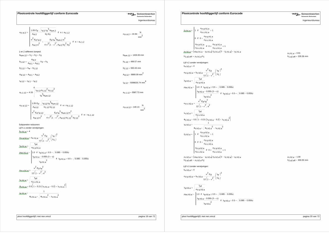
Plooicontrole hoofdliggerlijf conform Eurocode R GIngenieursbureau
σcr.sl.21.05 Ed
Asl.2
Isl.2 tw3
blum.2
b2 b3 a ac.1.2if
π2
Ed Isl.2
Asl.2 a2
Ed tw3
blum.2 a2
4 π2
1 ν2
Asl.2 b22
b32
a ac.1.2if
σcr.sl.2 24.94
N
mm2
1 en 2 stiffeners lumped:
blum.12 h1 h2 h3 blum.12 1430.00 mm
b1.12Asl.2
Asl.1 Asl.1h2 h1 b1.12 499.57 mm
b2.12 hw b1.12 b2.12 930.43 mm
Asl.12 Asl.1 Asl.2 Asl.12 8880.00 mm2
Isl.12 Isl.1 Isl.2Isl.12 9398025.74 mm
4
ac.1.12 4.33
4
Isl.12 b1.122
b2.122
tw3
blum.12
ac.1.12 5587.72 mm
σcr.sl.121.05 Ed
Asl.12
Isl.12 tw3
blum.12
b1.12 b2.12 a ac.1.12if
π2
Ed Isl.12
Asl.12 a2
Ed tw3
blum.12 a2
4 π2
1 ν2
Asl.12 b1.122
b2.122
a ac.1.12if
σcr.sl.12 140.13
N
mm2
σcr.p.h1.a kσ.h1.aπ
2Ed
12 1 ν2
tw
h1
2
λp.h1.afyd
σcr.p.h1.a
ρloc.h1.a 1.0 λp.h1.a 0.5 0.085 0.055ψif
λp.h1.a 0.055 3 ψ( )
λp.h1.a2
λp.h1.a 0.5 0.085 0.055ψif
σcr.c.h1.aπ
2Ed tw
2
12 1 ν2
a2
λc.h1.afyd
σcr.c.h1.a
Φc.h1.a 0.5 1 0.21 λc.h1.a 0.2 λc.h1.a2
χc.h1.a1
Φc.h1.a Φc.h1.a2
λc.h1.a2
kσ.h1.a 4
Lijf h.1 zonder verstijvingen:
Subpanelen reduceren:
plooi hoofdliggerlijf1 met nen.xmcd pagina 19 van 72
Plooicontrole hoofdliggerlijf conform Eurocode R GIngenieursbureau
ξc.h1.a 1σcr.p.h1.a
σcr.c.h1.a1if
0 0σcr.p.h1.a
σcr.c.h1.aif
σcr.p.h1.a
σcr.c.h1.a0
σcr.p.h1.a
σcr.c.h1.a 1if
ρc.h1.a ρloc.h1.a χc.h1.a ξc.h1.a 2 ξc.h1.a χc.h1.aρc.h1.a 0.91
h1.a2.eff ρc.h1.a h1 h1.a2.eff 328.36 mm
Lijf h.2 zonder verstijvingen:
kσ.h2.a 4
σcr.p.h2.a kσ.h2.aπ
2Ed
12 1 ν2
tw
h2
2
λp.h2.afyd
σcr.p.h2.a
ρloc.h2.a 1.0 λp.h2.a 0.5 0.085 0.055ψif
λp.h2.a 0.055 3 ψ( )
λp.h2.a2
λp.h2.a 0.5 0.085 0.055ψif
σcr.c.h2.aπ
2Ed tw
2
12 1 ν2
a2
λc.h2.afyd
σcr.c.h2.a
Φc.h2.a 0.5 1 0.21 λc.h2.a 0.2 λc.h2.a2
χc.h2.a1
Φc.h2.a Φc.h2.a2
λc.h2.a2
ξc.h2.a 1σcr.p.h2.a
σcr.c.h2.a1if
0 0σcr.p.h2.a
σcr.c.h2.aif
σcr.p.h2.a
σcr.c.h2.a0
σcr.p.h2.a
σcr.c.h2.a 1if
ρc.h2.a ρloc.h2.a χc.h2.a ξc.h2.a 2 ξc.h2.a χc.h2.a ρc.h2.a 1.00
h2.a2.eff ρc.h2.a h2 h2.a2.eff 300.00 mm
Lijf h.3 zonder verstijvingen:
kσ.h3.a 4
σcr.p.h3.a kσ.h3.aπ
2Ed
12 1 ν2
tw
h3
2
λp.h3.afyd
σcr.p.h3.a
ρloc.h3.a 1.0 λp.h3.a 0.5 0.085 0.055ψif
λp.h3.a 0.055 3 ψ( )
λp.h3.a2
λp.h3.a 0.5 0.085 0.055ψif
plooi hoofdliggerlijf1 met nen.xmcd pagina 20 van 72

Plooicontrole hoofdliggerlijf conform Eurocode R GIngenieursbureau
σcr.c.h3.aπ
2Ed tw
2
12 1 ν2
a2
λc.h3.afyd
σcr.c.h3.a
Φc.h3.a 0.5 1 0.21 λc.h3.a 0.2 λc.h3.a2
χc.h3.a1
Φc.h3.a Φc.h3.a2
λc.h3.a2
ξc.h3.a 1σcr.p.h3.a
σcr.c.h3.a1if
0 0σcr.p.h3.a
σcr.c.h3.aif
σcr.p.h3.a
σcr.c.h3.a0
σcr.p.h3.a
σcr.c.h3.a 1if
ρc.h3.a ρloc.h3.a χc.h3.a ξc.h3.a 2 ξc.h3.a χc.h3.aρc.h3.a 0.51
h3.a2.eff ρc.h3.a h3h3.a2.eff 395.64 mm
Verstijver 1 zonder verstijvingen:
kσ.v1.a 0.43
σcr.p.v1.a kσ.v1.aπ
2Ed
12 1 ν2
tv1
bv1
2
λp.v1.afyd
σcr.p.v1.a
ρloc.v1.a 1.0 λp.v1.a 0.748if
λp.v1.a 0.188
λp.v1.a2
λp.v1.a 0.748if
σcr.c.v1.aπ
2Ed tv1
2
12 1 ν2
a2
λc.v1.afyd
σcr.c.v1.a
Φc.v1.a 0.5 1 0.21 λc.v1.a 0.2 λc.v1.a2
χc.v1.a1
Φc.v1.a Φc.v1.a2
λc.v1.a2
ξc.v1.a 1σcr.p.v1.a
σcr.c.v1.a1if
0 0σcr.p.v1.a
σcr.c.v1.aif
σcr.p.v1.a
σcr.c.v1.a0
σcr.p.v1.a
σcr.c.v1.a 1if
ρc.v1.a ρloc.v1.a χc.v1.a ξc.v1.a 2 ξc.v1.a χc.v1.a ρc.v1.a 1.00
bv1.a2.eff ρc.v1.a bv1 bv1.a2.eff 140.00 mm
Verstijver 2 zonder verstijvingen:
plooi hoofdliggerlijf1 met nen.xmcd pagina 21 van 72
Plooicontrole hoofdliggerlijf conform Eurocode R GIngenieursbureau
kσ.v2.a 0.43
σcr.p.v2.a kσ.v2.aπ
2Ed
12 1 ν2
tv2
bv2
2
λp.v2.afyd
σcr.p.v2.a
ρloc.v2.a 1.0 λp.v2.a 0.748if
λp.v2.a 0.188
λp.v2.a2
λp.v2.a 0.748if
σcr.c.v2.aπ
2Ed tv2
2
12 1 ν2
a2
λc.v2.afyd
σcr.c.v2.a
Φc.v2.a 0.5 1 0.21 λc.v2.a 0.2 λc.v2.a2
χc.v2.a1
Φc.v2.a Φc.v2.a2
λc.v2.a2
ξc.v2.a 1σcr.p.v2.a
σcr.c.v2.a1if
0 0σcr.p.v2.a
σcr.c.v2.aif
σcr.p.v2.a
σcr.c.v2.a0
σcr.p.v2.a
σcr.c.v2.a 1if
ρc.v2.a ρloc.v2.a χc.v2.a ξc.v2.a 2 ξc.v2.a χc.v2.a ρc.v2.a 1.00
bv2.a2.eff ρc.v2.a bv2 bv2.a2.eff 0.00 mm
Global plate like behaviour:
Ach1
2h2
h3
2
tw bv1 tv1 bv2 tv2
Ac.eff.loch1.a2.eff
2h2.a2.eff
h3.a2.eff
2
tw bv1.a2.eff tv1 bv2.a2.eff tv2
βA.cAc.eff.loc
Ac
βA.c 0.82
σcr.sl.lum σcr.sl.1 σcr.sl.2 σcr.sl.1if σcr.sl.12 σcr.sl.1if
σcr.sl.2 σcr.sl.1 σcr.sl.2if σcr.sl.12 σcr.sl.2if
σcr.sl.12 σcr.sl.1 σcr.sl.12if σcr.sl.2 σcr.sl.12if
σcr.sl.lum 24.94N
mm2
λp.gl.aβA.c fyd
σcr.sl.lum
ρloc.gl.a 1.0 λp.gl.a 0.5 0.085 0.055ψif
λp.gl.a 0.055 3 ψ( )
λp.gl.a2
λp.gl.a 0.5 0.085 0.055ψif
ρloc.gl.a 0.33
σcr.c.gl.aπ
2Ed Isl.1
Asl.1 a2
plooi hoofdliggerlijf1 met nen.xmcd pagina 22 van 72

Plooicontrole hoofdliggerlijf conform Eurocode R GIngenieursbureau
λc.gl.aβA.c fyd
σcr.c.gl.a
ic.glIsl.1
Asl.1
ec.gl esti.1 esti.1bv1
2
tw
2 esti.1if
bv1
2
tw
2 esti.1
bv1
2
tw
2 esti.1 esti.1if
ec.gl 42.47 mm
αe 0.49 0.09ic.gl
ec.gl
Φc.gl.a 0.5 1 αe λc.gl.a 0.2 λc.gl.a2
χc.gl.a1
Φc.gl.a Φc.gl.a2
λc.gl.a2
χc.gl.a 0.08
ξc.gl.a 1σcr.sl.lum
σcr.c.gl.a1if
0 0σcr.sl.lum
σcr.c.gl.aif
σcr.sl.lum
σcr.c.gl.a0
σcr.sl.lum
σcr.c.gl.a 1if
ξc.gl.a 1.00
ρc.gl.a ρloc.gl.a χc.gl.a ξc.gl.a 2 ξc.gl.a χc.gl.a ρc.gl.a 0.33
tw.a2.eff ρc.gl.a tw
tv1.a2.eff ρc.gl.a tv1 tv1.a2.eff 4.65 mm
tv2.a2.eff ρc.gl.a tv2 tv2.a2.eff 0.00 mm
Oppervlak bruto met 2 verstijvingen:
Aa2 bfbL tfbL bfbR tfbR bfoL tfoL bfoR tfoR hw tw tv1 bv1 tv2 bv2 Afic.1 Afic.2 At1 At2 At3 At4
Aa2 77400.00 mm2
Statisch moment bruto met 2 verstijvingen:
Sa2 bfbL tfbLtfbL
2 bfbR tfbR
tfbR
2 hw tw tfbmax
hw
2
bfoL tfoL httfoL
2
bfoR tfoR httfoR
2
tv1 bv1 hv1 tv2 bv2 hv2 Afic.1 zfic.1 Afic.2 zfic.2 At1 zt1.bk zt1 At2 zt2.bk zt2 At3 zt3.bk zt3 At4 zt4.bk zt4
Zwaartepunt bruto met 2 verstijvingen: Sa2 45861200.00 mm3
eb.a2Sa2
Aa2
eb.a2 592.52 mmOppervlak netto met 2 verstijvingen:
Aa2.eff bfbL.a.eff tfbL bfbR.a.eff tfbR bfoL.a.eff tfoL bfoR.a.eff tfoRh1.a2.eff
2tw
h1.a2.eff
2tw.a2.eff
h2.a2.eff tw.a2.effh3.a2.eff
2tw.a2.eff
h3.a2.eff
2tw bv1.a2.eff tv1.a2.eff bv2.a2.eff tv2.a2.eff
ρfic.1.a Afic.1 ρfic.2.a Afic.2 At1.eff At2.eff At3.eff At4.eff
Aa2.eff 69303.62 mm2
Statisch moment netto met 2 verstijvingen:
Sa2.eff bfbL.a.eff tfbLtfbL
2 bfbR.a.eff tfbR
tfbR
2 bfoL.a.eff tfoL ht
tfoL
2
bfoR.a.eff tfoR httfoR
2
h1.a2.eff
2tw
h1.a2.eff
4tfbmax
h1.a2.eff
2tw.a2.eff h1
h1.a2.eff
4 tfbmax
h2.a2.eff tw.a2.eff h1 tfbmaxh2
2
h3.a2.eff
2tw.a2.eff h1 h2 tfbmax
h3.a2.eff
4
h3.a2.eff
2tw hw tfbmax
h3.a2.eff
4
bv1.a2.eff tv1.a2.eff hv1
bv2.a2.eff tv2.a2.eff hv2 ρfic.1.a Afic.1 zfic.1 ρfic.2.a Afic.2 zfic.2 At1.eff zt1.bk zt1.eff
At2.eff zt2.bk zt2.eff At3.eff zt3.bk zt3.eff At4.eff zt4.bk zt4.eff
tw.a2.eff 2.65 mm
plooi hoofdliggerlijf1 met nen.xmcd pagina 23 van 72
Plooicontrole hoofdliggerlijf conform Eurocode R GIngenieursbureau
Sa2.eff 40026378.19 mm3
Zwaartepunt netto met 2 verstijvingen:
eb.a2.effSa2.eff
Aa2.eff
eb.a2.eff 577.55 mm
Lijf met 2 verstijvers (DRUK)
plooi hoofdliggerlijf1 met nen.xmcd pagina 24 van 72

Plooicontrole hoofdliggerlijf conform Eurocode R GIngenieursbureau
Berekening gereduceerde doorsnede eigenschappen t.g.v. buigend moment:
Plate buckling effects due to direct stresses at the ultimate limit state (4)
Reduceren doorsnede flenzen t.g.v. buigend moment
Bovenflens reduceren:
Bruto oppervlakte:
Abi bfbL tfbL bfbR tfbR bfoL tfoL bfoR tfoR hw tw tv1 bv1 tv2 bv2Afic.1 Afic.2 At1 At2 At3 At4
Abi 77400.00 mm2
Bruto statisch moment:
Sbi bfbL tfbLtfbL
2 bfbR tfbR
tfbR
2 hw tw tfbmax
hw
2
bfoL tfoL httfoL
2
bfoR tfoR httfoR
2
tv1 bv1 hv1 tv2 bv2 hv2 Afic.1 zfic.1 Afic.2 zfic.2 At1 zt1.bk zt1 At2 zt2.bk zt2 At3 zt3.bk zt3 At4 zt4.bk zt4
Bruto zwaartepunt: Sbi 45861200.00 mm3
eb.biSbi
Abi
eb.bi 592.52 mmEffectieve oppervlakte (gereduceerde bovenflenzen):
Abi.eff bfbL.a.eff tfbL bfbR.a.eff tfbR bfoL tfoL bfoR tfoR hw tw tv1 bv1 tv2 bv2ρfic.1.m Afic.1 Afic.2 At1.eff At2.eff At3 At4
Abi.eff 77400.00 mm
2
Effectief statisch moment (gereduceerde bovenflenzen):
Sbi.eff bfbL.a.eff tfbLtfbL
2 bfbR.a.eff tfbR
tfbR
2 hw tw tfbmax
hw
2
bfoL tfoL httfoL
2
bfoR tfoR httfoR
2
tv1 bv1 hv1 tv2 bv2 hv2 ρfic.1.m Afic.1 zfic.1 Afic.2 zfic.2 At1.eff zt1.bk zt1.eff At2.eff zt2.bk zt2.eff
At3 zt3.bk zt3 At4 zt4.bk zt4
Effectief zwaartepunt (gereduceerde bovenflenzen):
Sbi.eff 45861200.00 mm3
eb.bi.effSbi.eff
Abi.eff
eb.bi.eff 592.52 mm
Iy.0.bi.eff1
12bfbL.a.eff tfbL
3 bfbR.a.eff tfbR
3 tw hw
3 bfoL tfoL
3 bfoR tfoR
3
bv1 tv13
bv2 tv23
ρfic.1.m Ific.1 Ific.2 It1.eff It2.eff It3 It4
Iy.c.bi.eff bfbL.a.eff tfbL eb.bi.efftfbL
2
2
bfbR.a.eff tfbR eb.bi.efftfbR
2
2
Aw eb.bi.eff tfbmaxhw
2
2
AfoL httfoL
2 eb.bi.eff
2
AfoR httfoR
2 eb.bi.eff
2
Av1 hv1 eb.bi.eff 2 Av2 hv2 eb.bi.eff 2
ρfic.1.m Afic.1 zfic.1 eb.bi.eff 2 Afic.2 zfic.2 eb.bi.eff 2 At1.eff zt1.bk zt1.eff eb.bi.eff 2
At2.eff zt2.bk zt2.eff eb.bi.eff 2 At3 zt3.bk zt3 eb.bi.eff 2 At4 zt4.bk zt4 eb.bi.eff 2
Effectief traagheidsmoment (gereduceerde bovenflenzen):
Iy.bi.eff Iy.0.bi.eff Iy.c.bi.effIy.bi.eff 3.4559 10
10 mm
4
e1.bi.eff eb.bi.eff
e2.bi.eff eb.bi.eff tfbmax
e3.bi.eff 0
e4.bi.eff eb.bi.eff ht tfomax
e5.bi.eff eb.bi.eff ht
e1.bi.eff 593 mm e2.bi.eff 553 mm e3.bi.eff 0 mm e4.bi.eff 877 mm e5.bi.eff 907 mm
Reduceren doorsnede flenzen t.g.v. buigend moment
plooi hoofdliggerlijf1 met nen.xmcd pagina 25 van 72
Plooicontrole hoofdliggerlijf conform Eurocode R GIngenieursbureau
Lijf zonder verstijver (MOMENT)
ψe4.bi.eff
e2.bi.eff ψ 1.59
bc.m0 hw ψ 0if
hw
1 ψ( )ψ 0if
bc.m0 552.52 mm
bt.m0 hw bc.m0 bt.m0 877.48 mm
bc.m0.sup bc.m02
5 ψ ψ 0if
0.4 bc.m0 ψ 0if
bc.m0.sup 221.01 mm
bc.m0.inf bc.m03 ψ
5 ψ ψ 0if
0.6 bc.m0 ψ 0if
bc.m0.inf 331.51 mm
kσ.w.m 4 ψ 1=if
8.2
1.05 ψ0 ψ 1if
7.8 ψ 0=if
7.81 6.29 ψ 9.78 ψ2
0 ψ 1if
23.9 ψ 1=if
5.98 1 ψ( )2
1 ψ 3if
5.98 1 3( )2
ψ 3if
kσ.w.m 40.06
σcr.p.w.m kσ.w.mπ
2Ed
12 1 ν2
tw
hw
2
λp.w.mfyd
σcr.p.w.m
λp.w.m 0.99
ρloc.w.m 1.0 λp.w.m 0.5 0.085 0.055ψif
λp.w.m 0.055 3 ψ( )
λp.w.m2
λp.w.m 0.5 0.085 0.055ψif
σcr.c.w.mπ
2Ed tw
2
12 1 ν2
a2
λc.w.mfyd
σcr.c.w.m
Φc.w.m 0.5 1 0.21 λc.w.m 0.2 λc.w.m2
χc.w.m1
Φc.w.m Φc.w.m2
λc.w.m2
plooi hoofdliggerlijf1 met nen.xmcd pagina 26 van 72

Plooicontrole hoofdliggerlijf conform Eurocode R GIngenieursbureau
ξc.w.m 1σcr.p.w.m
σcr.c.w.m1if
0 0σcr.p.w.m
σcr.c.w.mif
σcr.p.w.m
σcr.c.w.m0
σcr.p.w.m
σcr.c.w.m 1if
ρc.w.m ρloc.w.m χc.w.m ξc.w.m 2 ξc.w.m χc.w.mρc.w.m 0.93
bc.m0.sup.eff ρc.w.m bc.m0.supbc.m0.sup.eff 205.01 mm
bc.m0.inf.eff ρc.w.m bc.m0.infbc.m0.inf.eff 307.52 mm
Bruto oppervlakte:
Am0 bfbL tfbL bfbR tfbR bfoL tfoL bfoR tfoR hw tw Afic.1 Afic.2 At1 At2 At3 At4 bv1 tv1 bv2 tv2
Am0 77400.00 mm2
Bruto statisch moment:
Sm0 bfbL tfbLtfbL
2 bfbR tfbR
tfbR
2 hw tw tfbmax
hw
2
bfoL tfoL httfoL
2
bfoR tfoR httfoR
2
Afic.1 zfic.1
Afic.2 zfic.2 At1 zt1.bk zt1 At2 zt2.bk zt2 At3 zt3.bk zt3 At4 zt4.bk zt4 bv1 tv1 hv1 bv2 tv2 hv2
Sm0 45861200.00 mm3
Bruto zwaartepunt:
eb.m0Sm0
Am0
eb.m0 592.52 mm
Effectieve oppervlakte:
Am0.eff bfbL.a.eff tfbL bfbR.a.eff tfbR bfoL tfoL bfoR tfoR bc.m0.sup.eff bc.m0.inf.eff tw bt.m0 twρfic.1.m Afic.1 Afic.2 At1.eff At2.eff At3 At4 bv1 tv1 bv2 tv2
Am0.eff 77080.08 mm2
Effectief statisch moment:
Sm0.eff bfbL.a.eff tfbLtfbL
2 bfbR.a.eff tfbR
tfbR
2 bfoL tfoL ht
tfoL
2
bfoR tfoR httfoR
2
bt.m0 twbt.m0
2bc.m0.sup bc.m0.inf tfbmax
bc.m0.sup.eff twbc.m0.sup.eff
2tfbmax
bc.m0.inf.eff tw bc.m0.sup bc.m0.inf tfbmaxbc.m0.inf.eff
2
ρfic.1.m Afic.1 zfic.1 Afic.2 zfic.2
At1.eff zt1.bk zt1.eff At2.eff zt2.bk zt2.eff At3 zt3.bk zt3 At4 zt4.bk zt4 bv1 tv1 hv1 bv2 tv2 hv2
Sm0.eff 45776418.29 mm3
Effectief zwaartepunt:
eb.m0.effSm0.eff
Am0.eff
eb.m0.eff 593.88 mm
Iy.0.m0.eff1
12bfbL.a.eff tfbL
3 bfbR.a.eff tfbR
3 bfoL tfoL
3 bfoR tfoR
3
tw bc.m0.sup.eff3
tw bc.m0.inf.eff3
tw bt.m03
bv1 tv13
bv2 tv23
ρfic.1.m Ific.1 Ific.2 It1.eff It2.eff It3 It4
plooi hoofdliggerlijf1 met nen.xmcd pagina 27 van 72
Plooicontrole hoofdliggerlijf conform Eurocode R GIngenieursbureau
Iy.c.m0.eff bfbL.a.eff tfbL eb.m0.efftfbL
2
2
bfbR.a.eff tfbR eb.m0.efftfbR
2
2
bc.m0.sup.eff tw eb.m0.eff tfbmaxbc.m0.sup.eff
2
2
bc.m0.inf.eff tw eb.m0.eff tfbmax bc.m0.inf bc.m0.supbc.m0.inf.eff
2
2
bt.m0 tw eb.m0.eff tfbmax hwbt.m0
2
2
bfoL tfoL httfoL
2 eb.m0.eff
2
bfoR tfoR httfoR
2 eb.m0.eff
2
ρfic.1.m Afic.1 zfic.1 eb.m0.eff 2 Afic.2 zfic.2 eb.m0.eff 2 At1.eff zt1.bk zt1.eff eb.m0.eff 2
At2.eff zt2.bk zt2.eff eb.m0.eff 2 At3 zt3.bk zt3 eb.m0.eff 2 At4 zt4.bk zt4 eb.m0.eff 2
bv1 tv1 hv1 eb.m0.eff 2 bv2 tv2 hv2 eb.m0.eff 2
Effectief traagheidsmoment:
Iy.m0.eff Iy.0.m0.eff Iy.c.m0.effIy.m0.eff 3.4522 10
10 mm
4
Lijf zonder verstijver (MOMENT)
Lijf met 1 verstijver in drukzone (MOMENT)
Figure A.1: Notations for longitudinally stiffened plates (uit NEN-EN1993-1-5 pagina 40)
b1 h1 b1 360.00 mm
b2 h2 h3 b2 1070.00 mm
ψm1.b1eb.bi.eff b1 tfbmax
e2.bi.eff ψm1.b1 0.35
ψm1.b2 1eb.bi.eff b1 b2 tfbmax
eb.bi.eff b1 tfbmax 1if
eb.bi.eff b1 b2 tfbmax
eb.bi.eff b1 tfbmax otherwise
ψm1.b2 4.56
b1.m1.edge2
5 ψm1.b1b1 b1.m1.edge 154.79 mm
plooi hoofdliggerlijf1 met nen.xmcd pagina 28 van 72

Plooicontrole hoofdliggerlijf conform Eurocode R GIngenieursbureau
b1.m1.inf3 ψm1.b1
5 ψm1.b1b1 b1.m1.inf 205.21 mm
b2.m1.sup2
5 ψm1.b2b2 ψm1.b2 0if
0.4b2
1 ψm1.b2 ψm1.b2 0if
b2.m1.sup 77.01 mm
b2.m1.inf3 ψm1.b2
5 ψm1.b2b2 ψm1.b2 0if
0.6b2
1 ψm1.b2 ψm1.b2 0if
b2.m1.inf 115.51 mm
bt.m1 e4.bi.eff e4.bi.eff 0if
0 e4.bi.eff 0if
bt.m1 877.48 mm
blum b1 b2 blum 1430.00 mm
Asl b1.m1.inf b2.m1.sup tw bv1 tv1 Asl 4217.78 mm2
esti
bv1 tv1bv1
2
tw
2
Asl esti 34.39 mm
Isl1
12b1.m1.inf b2.m1.sup tw
3
1
12tv1 bv1
3 b1.m1.inf b2.m1.sup tw esti
2 bv1 tv1 esti
bv1
2
tw
2
2
Isl 8958728.93 mm4
ac.1 4.33
4
Isl b1 2 b2 2
tw3
blum ac.1 5026.22 mm
σcr.sl.1.11.05 Ed
Asl
Isl tw3
blum
b1 b2 a ac.1if
π2
Ed Isl
Asl a2
Ed tw3
blum a2
4 π2
1 ν2
Asl b1 2 b2 2 a ac.1if
σcr.sl.1.1 347.59
N
mm2
σcr.sl.1e2.bi.eff
e2.bi.eff h1σcr.sl.1.1 σcr.sl.1 997.55
N
mm2
Subpanelen reduceren:
Lijf h.1 zonder verstijvingen:
ψm1.b1 0.35
kσ.h1.m1 4 ψm1.b1 1=if
8.2
1.05 ψm1.b10 ψm1.b1 1if
7.8 ψm1.b1 0=if
7.81 6.29 ψm1.b1 9.78 ψm1.b12
0 ψm1.b1 1if
23.9 ψm1.b1 1=if
5.98 1 ψm1.b1 2 1 ψm1.b1 3if
plooi hoofdliggerlijf1 met nen.xmcd pagina 29 van 72
Plooicontrole hoofdliggerlijf conform Eurocode R GIngenieursbureau
σcr.p.h1.m1 kσ.h1.m1π
2Ed
12 1 ν2
tw
h1
2
λp.h1.m1fyd
σcr.p.h1.m1
ρloc.h1.m1 1.0 λp.h1.m1 0.5 0.085 0.055ψm1.b1if
λp.h1.m1 0.055 3 ψm1.b1
λp.h1.m12
λp.h1.m1 0.5 0.085 0.055ψm1.b1if
σcr.c.h1.m1π
2Ed tw
2
12 1 ν2
a2
λc.h1.m1fyd
σcr.c.h1.m1
ξc.h1.m1 1σcr.p.h1.m1
σcr.c.h1.m11if
0 0σcr.p.h1.m1
σcr.c.h1.m1if
σcr.p.h1.m1
σcr.c.h1.m10
σcr.p.h1.m1
σcr.c.h1.m1 1if
ρc.h1.m1 ρloc.h1.m1 χc.h1.m1 ξc.h1.m1 2 ξc.h1.m1 χc.h1.m1 ρc.h1.m1 1.00
b1.m1.edge.eff ρc.h1.m1 b1.m1.edge b1.m1.edge.eff 154.79 mm
b1.m1.inf.eff ρc.h1.m1 b1.m1.inf b1.m1.inf.eff 205.21 mm
Lijf h.23 zonder verstijvingen:
ψm1.b2 4.56
kσ.h23.m1 4 ψm1.b2 1=if
8.2
1.05 ψm1.b20 ψm1.b2 1if
7.8 ψm1.b2 0=if
7.81 6.29 ψm1.b2 9.78 ψm1.b22
0 ψm1.b2 1if
23.9 ψm1.b2 1=if
5.98 1 ψm1.b2 2 1 ψm1.b2 3if
95.68 ψm1.b2 3if
σcr.p.h23.m1 kσ.h23.m1π
2Ed
12 1 ν2
tw
h2 h3
2
λp.h23.m1fyd
σcr.p.h23.m1
Φc.h1.m1 0.5 1 0.21 λc.h1.m1 0.2 λc.h1.m12
χc.h1.m11
Φc.h1.m1 Φc.h1.m12
λc.h1.m12
plooi hoofdliggerlijf1 met nen.xmcd pagina 30 van 72

Plooicontrole hoofdliggerlijf conform Eurocode R GIngenieursbureau
ρloc.h23.m1 1.0 λp.h23.m1 0.5 0.085 0.055ψm1.b2if
λp.h23.m1 0.055 3 ψm1.b2
λp.h23.m12
λp.h23.m1 0.5 0.085 0.055ψm1.b2if
σcr.c.h23.m1π
2Ed tw
2
12 1 ν2
a2
λc.h23.m1fyd
σcr.c.h23.m1
Φc.h23.m1 0.5 1 0.21 λc.h23.m1 0.2 λc.h23.m12
χc.h23.m11
Φc.h23.m1 Φc.h23.m12
λc.h23.m12
ξc.h23.m1 1σcr.p.h23.m1
σcr.c.h23.m11if
0 0σcr.p.h23.m1
σcr.c.h23.m1if
σcr.p.h23.m1
σcr.c.h23.m10
σcr.p.h23.m1
σcr.c.h23.m1 1if
ρc.h23.m1 ρloc.h23.m1 χc.h23.m1 ξc.h23.m1 2 ξc.h23.m1 χc.h23.m1 ρc.h23.m1 1.00
b2.m1.sup.eff ρc.h23.m1 b2.m1.sup b2.m1.sup.eff 77.01 mm
b2.m1.inf.eff ρc.h23.m1 b2.m1.inf b2.m1.inf.eff 115.51 mm
bt.m1 877.48 mm
Verstijver 1 zonder verstijvingen:
ψ 1
kσ.v1.m1 0.43
σcr.p.v1.m1 kσ.v1.m1π
2Ed
12 1 ν2
tv1
bv1
2
λp.v1.m1fyd
σcr.p.v1.m1
ρloc.v1.m1 1.0 λp.v1.m1 0.748if
λp.v1.m1 0.188
λp.v1.m12
λp.v1.m1 0.748if
σcr.c.v1.m1π
2Ed tv1
2
12 1 ν2
a2
λc.v1.m1fyd
σcr.c.v1.m1
Φc.v1.m1 0.5 1 0.21 λc.v1.m1 0.2 λc.v1.m12
χc.v1.m11
Φc.v1.m1 Φc.v1.m12
λc.v1.m12
plooi hoofdliggerlijf1 met nen.xmcd pagina 31 van 72
Plooicontrole hoofdliggerlijf conform Eurocode R GIngenieursbureau
ξc.v1.m1 1σcr.p.v1.m1
σcr.c.v1.m11if
0 0σcr.p.v1.m1
σcr.c.v1.m1if
σcr.p.v1.m1
σcr.c.v1.m10
σcr.p.v1.m1
σcr.c.v1.m1 1if
ρc.v1.m1 ρloc.v1.m1 χc.v1.m1 ξc.v1.m1 2 ξc.v1.m1 χc.v1.m1 ρc.v1.m1 1.00
bv1.m1.eff ρc.v1.m1 bv1 bv1.m1.eff 140.00 mm
Global plate like behaviour:
ψe4.bi.eff
e2.bi.eff
ψ 1.59
Ac b1.m1.inf b2.m1.sup tw bv1 tv1
Ac.eff.loc b1.m1.inf.eff b2.m1.sup.eff tw bv1.m1.eff tv1
βA.cAc.eff.loc
Ac
βA.c 1.00
λp.gl.mβA.c fyd
σcr.sl.1
λp.gl.m 0.49
ρloc.gl.m 1.0 λp.gl.m 0.5 0.085 0.055ψif
λp.gl.m 0.055 3 ψ( )
λp.gl.m2
λp.gl.m 0.5 0.085 0.055ψif
ρloc.gl.m 1.00
σcr.c.gl.m.1π
2Ed Isl
Asl a2
σcr.c.gl.me2.bi.eff
e2.bi.eff h1σcr.c.gl.m.1
σcr.c.gl.m 56.15N
mm2
λc.gl.mβA.c fyd
σcr.c.gl.m
ic.glIsl
Asl
ec.gl esti estibv1
2
tw
2 estiif
bv1
2
tw
2 esti
bv1
2
tw
2 esti estiif
ec.gl 39.61 mm
αe 0.49 0.09ic.gl
ec.gl
Φc.gl.m 0.5 1 αe λc.gl.m 0.2 λc.gl.m2
χc.gl.m1
Φc.gl.m Φc.gl.m2
λc.gl.m2
plooi hoofdliggerlijf1 met nen.xmcd pagina 32 van 72

Plooicontrole hoofdliggerlijf conform Eurocode R GIngenieursbureau
ξc.gl.m 1σcr.sl.1
σcr.c.gl.m1if
0 0σcr.sl.1
σcr.c.gl.mif
σcr.sl.1
σcr.c.gl.m0
σcr.sl.1
σcr.c.gl.m 1if
ξc.gl.m 1.00
ρc.gl.m ρloc.gl.m χc.gl.m ξc.gl.m 2 ξc.gl.m χc.gl.mρc.gl.m 1.00
tw.m1.eff ρc.gl.m twtw.m1.eff 8.00 mm
tv1.m1.eff ρc.gl.m tv1 tv1.m1.eff 14.00 mm
Bruto oppervlakte:
Am1 bfbL tfbL bfbR tfbR bfoL tfoL bfoR tfoR hw tw tv1 bv1 tv2 bv2 Afic.1 Afic.2 At1 At2 At3 At4
Am1 77400.00 mm2
Bruto statisch moment:
Sm1 bfbL tfbLtfbL
2 bfbR tfbR
tfbR
2 hw tw tfbmax
hw
2
bfoL tfoL httfoL
2
bfoR tfoR httfoR
2
tv1 bv1 hv1 tv2 bv2 hv2 Afic.1 zfic.1 Afic.2 zfic.2 At1 zt1.bk zt1 At2 zt2.bk zt2 At3 zt3.bk zt3 At4 zt4.bk zt4
Sm1 45861200.00 mm3
Bruto zwaartepunt:
eb.m1Sm1
Am1
eb.m1 592.52 mm
Effectieve oppervlakte:
Am1.eff bfbL.a.eff tfbL bfbR.a.eff tfbR bfoL tfoL bfoR tfoRb1.m1.edge.eff tw b1.m1.inf.eff tw.m1.eff b2.m1.sup.eff tw.m1.eff
b2.m1.inf.eff tw bt.m1 tw bv1.m1.eff tv1.m1.eff ρfic.1.m Afic.1 Afic.2 At1.eff At2.eff At3 At4 tv2 bv2
Am1.eff 77400.00 mm2
Effectief statisch moment:
Sm1.eff bfbL.a.eff tfbLtfbL
2 bfbR.a.eff tfbR
tfbR
2 bfoL tfoL ht
tfoL
2
bfoR tfoR httfoR
2
b1.m1.edge.eff twb1.m1.edge.eff
2tfbmax
b1.m1.inf.eff tw.m1.eff b1 tfbmaxb1.m1.inf.eff
2
b2.m1.sup.eff tw.m1.eff b1 tfbmaxb2.m1.sup.eff
2
b2.m1.inf.eff tw b1 b2 tfbmax bt.m1b2.m1.inf.eff
2
bt.m1 tw b1 b2 tfbmaxbt.m1
2
bv1.m1.eff tv1.m1.eff hv1 ρfic.1.m Afic.1 zfic.1 Afic.2 zfic.2
At1.eff zt1.bk zt1.eff At2.eff zt2.bk zt2.eff At3 zt3.bk zt3 At4 zt4.bk zt4 bv2 tv2 hv2
Effectief zwaartepunt: Sm1.eff 45861200.00 mm3
eb.m1.effSm1.eff
Am1.eff
eb.m1.eff 592.52 mm
Iy.0.m1.eff1
12bfbL.a.eff tfbL
3 bfbR.a.eff tfbR
3 bfoL tfoL
3 bfoR tfoR
3
bv1.m1.eff tv1.m1.eff3
tw b1.m1.edge.eff3
tw.m1.effb1.m1.inf.eff3
tw.m1.eff b2.m1.sup.eff3
tw b2.m1.inf.eff3
tw bt.m13
bv2 tv23
ρfic.1.m Ific.1 Ific.2 It1.eff It2.eff It3 It4
plooi hoofdliggerlijf1 met nen.xmcd pagina 33 van 72
Plooicontrole hoofdliggerlijf conform Eurocode R GIngenieursbureau
Iy.c.m1.eff bfbL.a.eff tfbL eb.m1.efftfbL
2
2
bfbR.a.eff tfbR eb.m1.efftfbR
2
2
b1.m1.edge.eff tw eb.m1.eff tfbmaxb1.m1.edge.eff
2
2
b1.m1.inf.eff tw.m1.eff eb.m1.eff tfbmax b1b1.m1.inf.eff
2
2
b2.m1.sup.eff tw.m1.eff eb.m1.eff tfbmax b1b2.m1.sup.eff
2
2
b2.m1.inf.eff tw eb.m1.eff hw tfbmax bt.m1b2.m1.inf.eff
2
2
bt.m1 tw eb.m1.eff tfbmax hwbt.m1
2
2
bfoL tfoL httfoL
2 eb.m1.eff
2
bfoR tfoR httfoR
2 eb.m1.eff
2
bv1.m1.eff tv1.m1.eff hv1 eb.m1.eff 2 bv2 tv2 hv2 eb.m1.eff 2
ρfic.1.m Afic.1 zfic.1 eb.m1.eff 2 Afic.2 zfic.2 eb.m1.eff 2 At1.eff zt1.bk zt1.eff eb.m1.eff 2
At2.eff zt2.bk zt2.eff eb.m1.eff 2 At3 zt3.bk zt3 eb.m1.eff 2 At4 zt4.bk zt4 eb.m1.eff 2
Effectief traagheidsmoment:
Iy.m1.eff Iy.0.m1.eff Iy.c.m1.effIy.m1.eff 3.4559 10
10 mm
4
Lijf met 1 verstijver in drukzone (MOMENT)
Lijf met 2 verstijvers (MOMENT)
Lijf met 2 verstijvers:
Figure A.3: Notations for plate with two stiffeners in the compression zone (uit NEN-EN1993-1-5 pagina 41)
plooi hoofdliggerlijf1 met nen.xmcd pagina 34 van 72

Plooicontrole hoofdliggerlijf conform Eurocode R GIngenieursbureau
Figure A.1: Notations for longitudinally stiffened plates (uit NEN-EN1993-1-5 pagina 40)
b1 h1b1 360.00 mm
b2 h2b2 300.00 mm
b3 h3b3 770.00 mm
ψm2.b1eb.bi.eff b1 tfbmax
e2.bi.eff ψm2.b1 0.35
ψm2.b2 1eb.bi.eff b1 b2 tfbmax
eb.bi.eff b1 tfbmax 1if
eb.bi.eff b1 b2 tfbmax
eb.bi.eff b1 tfbmax otherwise
ψm2.b2 0.56
ψm2.b3 1eb.bi.eff b1 b2 b3 tfbmax
eb.bi.eff b1 b2 tfbmax 1if
eb.bi.eff b1 b2 b3 tfbmax
eb.bi.eff b1 b2 tfbmax otherwise
ψm2.b3 1.00
b1.m2.edge2
5 ψm2.b1b1 b1.m2.edge 154.79 mm
b1.m2.inf3 ψm2.b1
5 ψm2.b1b1 b1.m2.inf 205.21 mm
b2.m2.sup2
5 ψm2.b2b2 b2.m2.sup 107.95 mm
b2.m2.inf3 ψm2.b2
5 ψm2.b2b2 b2.m2.inf 192.05 mm
b3.m2.sup2
5 ψm2.b3b3 ψm2.b3 0if
0.4b3
1 ψm2.b3 ψm2.b3 0if
b3.m2.sup 385.00 mm
b3.m2.inf3 ψm2.b3
5 ψm2.b3b3 ψm2.b3 0if
0.6b3
1 ψm2.b3 ψm2.b3 0if
b3.m2.inf 385.00 mm
bt.m2 e4.bi.eff e4.bi.eff 0if
0 e4.bi.eff 0if
bt.m2 877.48 mm
1 stiffener lumped:
blum.1 b1 b2 blum.1 660.00 mm
plooi hoofdliggerlijf1 met nen.xmcd pagina 35 van 72
Plooicontrole hoofdliggerlijf conform Eurocode R GIngenieursbureau
Asl.1 b1.m2.inf b2.m2.sup tw bv1 tv1 Asl.1 4465.28 mm2
esti.1
bv1 tv1bv1
2
tw
2
Asl.1 esti.1 32.48 mm
Isl.11
12b1.m2.inf b2.m2.sup tw
3
1
12tv1 bv1
3 b1.m2.inf b2.m2.sup tw esti.1
2 bv1 tv1 esti.1
bv1
2
tw
2
2
Isl.1 9236509.78 mm4
ac.1.1 4.33
4
Isl.1 b12
b22
tw3
blum.1 ac.1.1 3253.67 mm
σcr.sl.1.11.05 Ed
Asl.1
Isl.1 tw3
blum.1
b1 b2 a ac.1.1if
π2
Ed Isl.1
Asl.1 a2
Ed tw3
blum.1 a2
4 π2
1 ν2
Asl.1 b12
b22
a ac.1.1if
σcr.sl.1.1 807.79N
mm2
σcr.sl.1e2.bi.eff
e2.bi.eff h1σcr.sl.1.1 σcr.sl.1 2318.28
N
mm2
2 stiffener lumped:
blum.2 b2 b3 blum.2 1070.00 mm
Asl.2 b2.m2.inf b3.m2.sup tw bv2 tv2 Asl.2 4616.42 mm2
esti.2
bv2 tv2bv2
2
tw
2
Asl.2 esti.2 8.67 10
10 mm
Isl.21
12b2.m2.inf b3.m2.sup tw
3
1
12tv2 bv2
3 b2.m2.inf b3.m2.sup tw esti.2
2 bv2 tv2 esti.2
bv2
2
tw
2
2
Isl.2 24620.91 mm4
ac.1.2 4.33
4
Isl.2 b22
b32
tw3
blum.2
ac.1.2 958.20 mm
σcr.sl.2.11.05 Ed
Asl.2
Isl.2 tw3
blum.2
b2 b3 a ac.1.2if
π2
Ed Isl.2
Asl.2 a2
Ed tw3
2 blum.2 a2
4 π2
1 ν2
Asl.2 b22
b32
a ac.1.2if
σcr.sl.2.1 24.01N
mm2
σcr.sl.2e2.bi.eff
e2.bi.eff h1 h2σcr.sl.2.1 σcr.sl.2 123.45
N
mm2
1 en 2 stiffeners lumped:
blum.12 h1 h2 h3 blum.12 1430.00 mm
b1.12Asl.2 e1.bi.eff h1 h2
Asl.1 e1.bi.eff h1 Asl.2 e1.bi.eff h1 h2 h2 h1
b1.12 231.41 mm
b2.12 hw b1.12 b2.12 1198.59 mm
Asl.12 Asl.1 Asl.2 Asl.12 9081.71 mm2
plooi hoofdliggerlijf1 met nen.xmcd pagina 36 van 72

Plooicontrole hoofdliggerlijf conform Eurocode R GIngenieursbureau
Isl.12 Isl.1 Isl.2Isl.12 9261130.69 mm
4
ac.1.12 4.33
4
Isl.12 b1.122
b2.122
tw3
blum.12
ac.1.12 4300.63 mm
σcr.sl.12.11.05 Ed
Asl.12
Isl.12 tw3
blum.12
b1.12 b2.12 a ac.1.12if
π2
Ed Isl.12
Asl.12 a2
Ed tw3
blum.12 a2
4 π2
1 ν2
Asl.12 b1.122
b2.122
a ac.1.12if
σcr.sl.12.1 227.94
N
mm2
σcr.sl.12e2.bi.eff
e2.bi.eff b1.12σcr.sl.12.1 σcr.sl.12 392.21
N
mm2
Subpanelen reduceren:
Lijf h.1 zonder verstijvingen:
ψm2.b1 0.35
σcr.p.h1.m2 kσ.h1.m2π
2Ed
12 1 ν2
tw
h1
2
λp.h1.m2fyd
σcr.p.h1.m2
ρloc.h1.m2 1.0 λp.h1.m2 0.5 0.085 0.055ψm2.b1if
λp.h1.m2 0.055 3 ψm2.b1
λp.h1.m22
λp.h1.m2 0.5 0.085 0.055ψm2.b1if
σcr.c.h1.m2π
2Ed tw
2
12 1 ν2
a2
λc.h1.m2fyd
σcr.c.h1.m2
Φc.h1.m2 0.5 1 0.21 λc.h1.m2 0.2 λc.h1.m22
χc.h1.m21
Φc.h1.m2 Φc.h1.m22
λc.h1.m22
ξc.h1.m2 1σcr.p.h1.m2
σcr.c.h1.m21if
0 0σcr.p.h1.m2
σcr.c.h1.m2if
σcr.p.h1.m2
σcr.c.h1.m20
σcr.p.h1.m2
σcr.c.h1.m2 1if
ξc.h1.m2 1.00
kσ.h1.m2 4 ψm2.b1 1=if
8.2
1.05 ψm2.b10 ψm2.b1 1if
7.8 ψm2.b1 0=if
7.81 6.29 ψm2.b1 9.78 ψm2.b12
0 ψm2.b1 1if
23.9 ψm2.b1 1=if
5.98 1 ψm2.b1 2 1 ψm2.b1 3if
plooi hoofdliggerlijf1 met nen.xmcd pagina 37 van 72
Plooicontrole hoofdliggerlijf conform Eurocode R GIngenieursbureau
ρc.h1.m2 ρloc.h1.m2 χc.h1.m2 ξc.h1.m2 2 ξc.h1.m2 χc.h1.m2 ρc.h1.m2 1.00
b1.m2.edge.eff ρc.h1.m2 b1.m2.edge b1.m2.edge.eff 154.79 mm
b1.m2.inf.eff ρc.h1.m2 b1.m2.inf b1.m2.inf.eff 205.21 mm
Lijf h.2 zonder verstijvingen:
ψm2.b2 0.56
kσ.h2.m2 4 ψm2.b2 1=if
8.2
1.05 ψm2.b20 ψm2.b2 1if
7.8 ψm2.b2 0=if
7.81 6.29 ψm2.b2 9.78 ψm2.b22
0 ψm2.b2 1if
23.9 ψm2.b2 1=if
5.98 1 ψm2.b2 2 1 ψm2.b2 3if
5.98 1 3( )2
ψm2.b2 3if
σcr.p.h2.m2 kσ.h2.m2π
2Ed
12 1 ν2
tw
h2
2
λp.h2.m2fyd
σcr.p.h2.m2
ρloc.h2.m2 1.0 λp.h2.m2 0.5 0.085 0.055ψm2.b2if
λp.h2.m2 0.055 3 ψm2.b2
λp.h2.m22
λp.h2.m2 0.5 0.085 0.055ψm2.b2if
σcr.c.h2.m2π
2Ed tw
2
12 1 ν2
a2
λc.h2.m2fyd
σcr.c.h2.m2
Φc.h2.m2 0.5 1 0.21 λc.h2.m2 0.2 λc.h2.m22
χc.h2.m21
Φc.h2.m2 Φc.h2.m22
λc.h2.m22
ξc.h2.m2 1σcr.p.h2.m2
σcr.c.h2.m21if
0 0σcr.p.h2.m2
σcr.c.h2.m2if
σcr.p.h2.m2
σcr.c.h2.m20
σcr.p.h2.m2
σcr.c.h2.m2 1if
ξc.h2.m2 1.00
ρc.h2.m2 ρloc.h2.m2 χc.h2.m2 ξc.h2.m2 2 ξc.h2.m2 χc.h2.m2 ρc.h2.m2 1.00
b2.m2.sup.eff ρc.h2.m2 b2.m2.sup b2.m2.sup.eff 107.95 mm
b2.m2.inf.eff ρc.h2.m2 b2.m2.inf b2.m2.inf.eff 192.05 mm
Lijf h.3 zonder verstijvingen:
ψm2.b3 1.00
plooi hoofdliggerlijf1 met nen.xmcd pagina 38 van 72

Plooicontrole hoofdliggerlijf conform Eurocode R GIngenieursbureau
kσ.h3.m2 4 ψm2.b3 1=if
8.2
1.05 ψm2.b30 ψm2.b3 1if
7.8 ψm2.b3 0=if
7.81 6.29 ψm2.b3 9.78 ψm2.b32
0 ψm2.b3 1if
23.9 ψm2.b3 1=if
5.98 1 ψm2.b3 2 1 ψm2.b3 3if
5.98 1 3( )2
ψm2.b3 3if
σcr.p.h3.m2 kσ.h3.m2π
2Ed
12 1 ν2
tw
h3
2
λp.h3.m2fyd
σcr.p.h3.m2
ρloc.h3.m2 1.0 λp.h3.m2 0.5 0.085 0.055ψm2.b3if
λp.h3.m2 0.055 3 ψm2.b3
λp.h3.m22
λp.h3.m2 0.5 0.085 0.055ψm2.b3if
σcr.c.h3.m2π
2Ed tw
2
12 1 ν2
a2
λc.h3.m2fyd
σcr.c.h3.m2
Φc.h3.m2 0.5 1 0.21 λc.h3.m2 0.2 λc.h3.m22
χc.h3.m21
Φc.h3.m2 Φc.h3.m22
λc.h3.m22
ξc.h3.m2 1σcr.p.h3.m2
σcr.c.h3.m21if
0 0σcr.p.h3.m2
σcr.c.h3.m2if
σcr.p.h3.m2
σcr.c.h3.m20
σcr.p.h3.m2
σcr.c.h3.m2 1if
ξc.h3.m2 1.00
ρc.h3.m2 ρloc.h3.m2 χc.h3.m2 ξc.h3.m2 2 ξc.h3.m2 χc.h3.m2ρc.h3.m2 0.51
b3.m2.sup.eff ρc.h3.m2 b3.m2.supb3.m2.sup.eff 197.82 mm
b3.m2.inf.eff ρc.h3.m2 b3.m2.infb3.m2.inf.eff 197.82 mm
bt.m2 877.48 mmVerstijver 1 zonder verstijvingen:
ψ 1
kσ.v1.m2 0.43
σcr.p.v1.m2 kσ.v1.m2π
2Ed
12 1 ν2
tv1
bv1
2
λp.v1.m2fyd
σcr.p.v1.m2
ρloc.v1.m2 1.0 λp.v1.m2 0.748if
λp.v1.m2 0.188
λp.v1.m22
λp.v1.m2 0.748if
plooi hoofdliggerlijf1 met nen.xmcd pagina 39 van 72
Plooicontrole hoofdliggerlijf conform Eurocode R GIngenieursbureau
σcr.c.v1.m2π
2Ed tv1
2
12 1 ν2
a2
λc.v1.m2fyd
σcr.c.v1.m2
Φc.v1.m2 0.5 1 0.21 λc.v1.m2 0.2 λc.v1.m22
χc.v1.m21
Φc.v1.m2 Φc.v1.m22
λc.v1.m22
ξc.v1.m2 1σcr.p.v1.m2
σcr.c.v1.m21if
0 0σcr.p.v1.m2
σcr.c.v1.m2if
σcr.p.v1.m2
σcr.c.v1.m20
σcr.p.v1.m2
σcr.c.v1.m2 1if
ξc.v1.m2 1.00
ρc.v1.m2 ρloc.v1.m2 χc.v1.m2 ξc.v1.m2 2 ξc.v1.m2 χc.v1.m2 ρc.v1.m2 1.00
bv1.m2.eff ρc.v1.m2 bv1 bv1.m2.eff 140.00 mm
Verstijver 2 zonder verstijvingen:
ψ 1
kσ.v2.m2 0.43
σcr.p.v2.m2 kσ.v2.m2π
2Ed
12 1 ν2
tv2
bv2
2
λp.v2.m2fyd
σcr.p.v2.m2
ρloc.v2.m2 1.0 λp.v2.m2 0.748if
λp.v2.m2 0.188
λp.v2.m22
λp.v2.m2 0.748if
σcr.c.v2.m2π
2Ed tv2
2
12 1 ν2
a2
λc.v2.m2fyd
σcr.c.v2.m2
Φc.v2.m2 0.5 1 0.21 λc.v2.m2 0.2 λc.v2.m22
χc.v2.m21
Φc.v2.m2 Φc.v2.m22
λc.v2.m22
ξc.v2.m2 1σcr.p.v2.m2
σcr.c.v2.m21if
0 0σcr.p.v2.m2
σcr.c.v2.m2if
σcr.p.v2.m2
σcr.c.v2.m20
σcr.p.v2.m2
σcr.c.v2.m2 1if
ξc.v2.m2 1.00
ρc.v2.m2 ρloc.v2.m2 χc.v2.m2 ξc.v2.m2 2 ξc.v2.m2 χc.v2.m2 ρc.v2.m2 1.00
bv2.m2.eff ρc.v2.m2 bv2 bv2.m2.eff 0.00 mm
Global plate like behaviour:
ψe4.bi.eff
e2.bi.eff ψ 1.59
Ac b1.m2.inf b2.m2.sup b2.m2.inf b3.m2.sup tw bv1 tv1 bv2 tv2
plooi hoofdliggerlijf1 met nen.xmcd pagina 40 van 72

Plooicontrole hoofdliggerlijf conform Eurocode R GIngenieursbureau
Ac.eff.loc b1.m2.inf.eff b2.m2.sup.eff b2.m2.inf.eff b3.m2.sup.eff tw bv1.m2.eff tv1 bv2.m2.eff tv2
βA.cAc.eff.loc
Ac
βA.c 0.84
σcr.sl.lum σcr.sl.1 σcr.sl.2 σcr.sl.1if σcr.sl.12 σcr.sl.1if
σcr.sl.2 σcr.sl.1 σcr.sl.2if σcr.sl.12 σcr.sl.2if
σcr.sl.12 σcr.sl.1 σcr.sl.12if σcr.sl.2 σcr.sl.12if
σcr.sl.lum 123.45N
mm2
λp.gl.m2βA.c fyd
σcr.sl.lum
λp.gl.m2 1.26
ρloc.gl.m2 1.0 λp.gl.m2 0.5 0.085 0.055ψif
λp.gl.m2 0.055 3 ψ( )
λp.gl.m22
λp.gl.m2 0.5 0.085 0.055ψif
ρloc.gl.m2 0.74
σcr.c.gl.m.2π
2Ed Isl.1
Asl.1 a2
σcr.c.gl.m2e2.bi.eff
e2.bi.eff h1σcr.c.gl.m.2
σcr.c.gl.m2 54.68N
mm2
λc.gl.m2βA.c fyd
σcr.c.gl.m2
ic.glIsl.1
Asl.1
ec.gl esti.1 esti.1bv1
2
tw
2 esti.1if
bv1
2
tw
2 esti.1
bv1
2
tw
2 esti.1 esti.1if
ec.gl 41.52 mm
αe 0.49 0.09ic.gl
ec.gl
Φc.gl.m2 0.5 1 αe λc.gl.m2 0.2 λc.gl.m22
χc.gl.m21
Φc.gl.m2 Φc.gl.m22
λc.gl.m22
ξc.gl.m2 1σcr.sl.lum
σcr.c.gl.m21if
0 0σcr.sl.lum
σcr.c.gl.m2if
σcr.sl.lum
σcr.c.gl.m20
σcr.sl.lum
σcr.c.gl.m2 1if
ξc.gl.m2 0.00
ρc.gl.m2 ρloc.gl.m2 χc.gl.m2 ξc.gl.m2 2 ξc.gl.m2 χc.gl.m2ρc.gl.m2 0.21
tw.m2.eff ρc.gl.m2 twtw.m2.eff 1.65 mm
tv1.m2.eff ρc.gl.m2 tv1tv1.m2.eff 2.89 mm
tv2.m2.eff ρc.gl.m2 tv2
tv2.m2.eff 0.00 mm
Bruto oppervlakte:
Am2 bfbL tfbL bfbR tfbR bfoL tfoL bfoR tfoR hw tw tv1 bv1 tv2 bv2 Afic.1 Afic.2 At1 At2 At3 At4
plooi hoofdliggerlijf1 met nen.xmcd pagina 41 van 72
Plooicontrole hoofdliggerlijf conform Eurocode R GIngenieursbureau
Am2 77400.00 mm2
Bruto statisch moment:
Sm2 bfbL tfbLtfbL
2 bfbR tfbR
tfbR
2 hw tw tfbmax
hw
2
bfoL tfoL httfoL
2
bfoR tfoR httfoR
2
tv1 bv1 hv1 tv2 bv2 hv2 Afic.1 zfic.1 Afic.2 zfic.2 At1 zt1.bk zt1 At2 zt2.bk zt2 At3 zt3.bk zt3 At4 zt4.bk zt4
Sm2 45861200.00 mm3
Bruto zwaartepunt:
eb.m2Sm2
Am2
eb.m2 592.52 mmEffectieve oppervlakte:
Am2.eff bfbL.a.eff tfbL bfbR.a.eff tfbR bfoL tfoL bfoR tfoRbv1.m2.eff tv1.m2.eff bv2.m2.eff tv2.m2.eff
b1.m2.edge.eff tw b1.m2.inf.eff tw.m2.eff b2.m2.sup.eff tw.m2.eff
b2.m2.inf.eff tw.m2.eff b3.m2.sup.eff tw.m2.eff b3.m2.inf.eff tw bt.m2 tw
ρfic.1.m Afic.1 Afic.2 At1.eff At2.eff At3 At4
Am2.eff 75405.89 mm2
Effectief statisch moment:
Sm2.eff bfbL.a.eff tfbLtfbL
2 bfbR.a.eff tfbR
tfbR
2 bfoL tfoL ht
tfoL
2
bfoR tfoR httfoR
2
bv1.m2.eff tv1.m2.eff hv1 bv2.m2.eff tv2.m2.eff hv2 b1.m2.edge.eff tw tfbmaxb1.m2.edge.eff
2
b1.m2.inf.eff tw.m2.eff tfbmax b1b1.m2.inf.eff
2
b2.m2.sup.eff tw.m2.eff tfbmax b1b2.m2.sup.eff
2
b2.m2.inf.eff tw.m2.eff tfbmax b1 b2b2.m2.inf.eff
2
b3.m2.sup.eff tw.m2.eff tfbmax b1 b2b3.m2.sup.eff
2
b3.m2.inf.eff tw tfbmax b1 b2 b3.m2.sup b3.m2.infb3.m2.inf.eff
2
bt.m2 tw ht tfomaxbt.m2
2
ρfic.1.m Afic.1 zfic.1 Afic.2 zfic.2 At1.eff zt1.bk zt1.eff At2.eff zt2.bk zt2.eff At3 zt3.bk zt3 At4 zt4.bk zt4
Sm2.eff 46790354.79 mm3
Effectief zwaartepunt:
eb.m2.effSm2.eff
Am2.eff
eb.m2.eff 620.51 mm
Iy.0.m2.eff1
12bfbL.a.eff tfbL
3 bfbR.a.eff tfbR
3 bfoL tfoL
3 bfoR tfoR
3 bv1.m2.eff tv1.m2.eff
3
bv2.m2.eff tv2.m2.eff3
tw b1.m2.edge.eff3
tw.m2.effb1.m2.inf.eff3
tw.m2.eff b2.m2.sup.eff3
tw.m2.eff b2.m2.inf.eff3
tw.m2.eff b3.m2.sup.eff3
tw b3.m2.inf.eff3
tw bt.m23
ρfic.1.m Ific.1 Ific.2 It1.eff It2.eff It3 It4
plooi hoofdliggerlijf1 met nen.xmcd pagina 42 van 72

Plooicontrole hoofdliggerlijf conform Eurocode R GIngenieursbureau
Iy.c.m2.eff bfbL.a.eff tfbL eb.m2.efftfbL
2
2
bfbR.a.eff tfbR eb.m2.efftfbR
2
2
b1.m2.edge.eff tw eb.m2.eff tfbmaxb1.m2.edge.eff
2
2
b1.m2.inf.eff tw.m2.eff eb.m2.eff tfbmax b1b1.m2.inf.eff
2
2
b2.m2.sup.eff tw.m2.eff eb.m2.eff tfbmax b1b2.m2.sup.eff
2
2
b2.m2.inf.eff tw.m2.eff eb.m2.eff tfbmax b1 b2b2.m2.inf.eff
2
2
b3.m2.sup.eff tw.m2.eff eb.m2.eff tfbmax b1 b2b3.m2.sup.eff
2
2
b3.m2.inf.eff tw eb.m2.eff tfbmax b1 b2 b3.m2.sup b3.m2.infb3.m2.inf.eff
2
2
bt.m2 tw eb.m2.eff tfbmax hwbt.m2
2
2
bfoL tfoL httfoL
2 eb.m2.eff
2
bfoR tfoR httfoR
2 eb.m2.eff
2
bv1.m2.eff tv1.m2.eff hv1 eb.m2.eff 2
bv2.m2.eff tv2.m2.eff hv2 eb.m2.eff 2 ρfic.1.m Afic.1 zfic.1 eb.m2.eff 2 Afic.2 zfic.2 eb.m2.eff 2
At1.eff zt1.bk zt1.eff eb.m2.eff 2 At2.eff zt2.bk zt2.eff eb.m2.eff 2 At3 zt3.bk zt3 eb.m2.eff 2
At4 zt4.bk zt4 eb.m2.eff 2
Effectief traagheidsmoment:
Iy.m2.eff Iy.0.m2.eff Iy.c.m2.eff Iy.m2.eff 3.5289 1010
mm4
Lijf met 2 verstijvers (MOMENT)
plooi hoofdliggerlijf1 met nen.xmcd pagina 43 van 72
Plooicontrole hoofdliggerlijf conform Eurocode R GIngenieursbureau
rigidend
Check Box
rigidend 0.00
Schuifkracht zonder verstijver
Restance to shear (5)
Toetsnodig 1hw
tw72
ε
ηif
0hw
tw72
ε
ηif
Toetsnodig 1.00
kτ.s0 4 5.34hw
a
2
a
hw1.0if
5.34 4hw
a
2
a
hw1.0if
kτ.s0 5.38
σEπ
2Ed
12 1 ν2
tw
hw
2
λτ.s0
fyd
3
σE kτ.s0
λτ.s0 2.06
χw.s0.rigid η λτ.s00.83
ηif
0.83
λτ.s0
0.83
ηλτ.s0 1.08if
1.37
0.7 λτ.s0λτ.s0 1.08if
χw.s0.rigid 0.50
χw.s0.nonrigid η λτ.s00.83
ηif
0.83
λτ.s0λτ.s0
0.83
ηif
χw.s0.nonrigid 0.40
χw.s0 χw.s0.rigid rigidend 1=if
χw.s0.nonrigid rigidend 0=if
χw.s0 0.40
Vb.rd hw twη fyd
3
Maximale toelaatbare dwarskracht:
Vbw.rd.s0 Vb.rd Vb.rd χw.s0 hw twfyd
3if
χw.s0 hw twfyd
3 χw.s0 hw tw
fyd
3 Vb.rdif
Vbw.rd.s0 625.03 kN
Bijdrage van flenzen verwaarlozen vanwege momenten
plooi hoofdliggerlijf1 met nen.xmcd pagina 44 van 72

Plooicontrole hoofdliggerlijf conform Eurocode R GIngenieursbureau
Schuifkracht zonder verstijver
Schuifkracht met 1 verstijver
Restance to shear (5)
b1 h1
b1 360.00 mmb2 h2 h3
b2 1070.00 mm
beff.1 15 ε tw 15 ε tw1
2b1if
1
2b1 15 ε tw
1
2b1if
beff.1 120.00 mm
beff.2 15 ε tw 15 ε tw1
2b2if
1
2b2 15 ε tw
1
2b2if
beff.2 120.00 mm
Asl.s1 beff.1 beff.2 tw bv1 tv1
Asl.s1 3880.00 mm2
esti.s1
bv1 tv1bv1
2
tw
2
Asl.s1
esti.s1 37.38 mm
Isl.s11
12beff.1 beff.2 tw
3 bv1
3tv1
beff.1 beff.2 tw esti.s1
2 bv1 tv1 esti.s1
bv1
2
tw
2
2
Isl.s1 8522728.80 mm4
kτsl.s12.1
tw
3Isl.s1
hw
2.1
tw
3Isl.s1
hw 9
hw
a
2
4
Isl.s1
tw3
hw
3
if
9hw
a
2
4
Isl.s1
tw3
hw
3
9hw
a
2
4
Isl.s1
tw3
hw
3
2.1
tw
3Isl.s1
hwif
kτsl.s1 4.76
kτ1.1.s1 4 5.34hw
a
2
kτsl.s1a
hw1if
5.34 4hw
a
2
kτsl.s1a
hw1if
kτ1.1.s1 10.14
kτ1.2.s1 4.1
6.3 0.18Isl.s1
tw3
hw
a
hw
2 2.2
3Isl.s1
tw3
hw
kτ1.2.s1 9.16
kτ1.s1 kτ1.1.s1a
hw3if
kτ1.2.s1a
hw3if
kτ1.s1 10.14
σEπ
2Ed
12 1 ν2
tw
hw
2
plooi hoofdliggerlijf1 met nen.xmcd pagina 45 van 72
Plooicontrole hoofdliggerlijf conform Eurocode R GIngenieursbureau
λτ1.s1
fyd
3
σE kτ1.s1 λτ1.s1 1.50
Suppanelen berekenen:
Lijf h.1 zonder verstijvingen:
kτ2.s1 4 5.34b1
a
2
a
b11.0if
5.34 4b1
a
2
a
b11.0if
kτ2.s1 5.34
σEπ
2Ed
12 1 ν2
tw
b1
2
λτ2.s1
fyd
3
σE kτ2.s1
λτ2.s1 0.52
Lijf h.2 zonder verstijvingen:
kτ3.s1 4 5.34b2
a
2
a
b21.0if
5.34 4b2
a
2
a
b21.0if
kτ3.s1 5.36
σEπ
2Ed
12 1 ν2
tw
b2
2
λτ3.s1
fyd
3
σE kτ3.s1 λτ3.s1 1.54
λτ.s1 λτ1.s1 λτ2.s1 λτ1.s1if λτ3.s1 λτ1.s1if
λτ2.s1 λτ1.s1 λτ2.s1if λτ3.s1 λτ2.s1if
λτ3.s1 λτ1.s1 λτ3.s1if λτ2.s1 λτ3.s1if
λτ.s1 1.54
χw.s1.rigid η λτ.s10.83
ηif
0.83
λτ.s1
0.83
ηλτ.s1 1.08if
1.37
0.7 λτ.s1λτ.s1 1.08if
χw.s1.rigid 0.61
χw.s1.nonrigid η λτ.s10.83
ηif
0.83
λτ.s1λτ.s1
0.83
ηif
χw.s1.nonrigid 0.54
χw.s1 χw.s1.rigid rigidend 1=if
χw.s1.nonrigid rigidend 0=if
χw.s1 0.54
plooi hoofdliggerlijf1 met nen.xmcd pagina 46 van 72

Plooicontrole hoofdliggerlijf conform Eurocode R GIngenieursbureau
Vb.rd hw twη fyd
3
Maximale toelaatbare dwarskracht:
Vbw.rd.s1 Vb.rd Vb.rd χw.s1 hw twfyd
3if
χw.s1 hw twfyd
3 χw.s1 hw tw
fyd
3 Vb.rdif
Vbw.rd.s1 834.08 kN
Bijdrage van flenzen verwaarlozen vanwege momenten
Schuifkracht met 1 verstijver
Schuifkracht met 2 verstijvers
Restance to shear (5)b1 h1 b1 360.00 mm
b2 h2 b2 300.00 mm
b3 h3 b3 770.00 mm
beff.1 15 ε tw 15 ε tw1
2b1if
1
2b1 15 ε tw
1
2b1if
beff.1 120.00 mm
beff.2 15 ε tw 15 ε tw1
2b2if
1
2b2 15 ε tw
1
2b2if
beff.2 120.00 mm
beff.3 15 ε tw 15 ε tw1
2b3if
1
2b3 15 ε tw
1
2b3if
beff.3 120.00 mm
Asl.s2 beff.1 beff.2 tw beff.2 beff.3 tw bv1 tv1 bv2 tv2Asl.s2 5800.00 mm
2
esti.s2
bv1 tv1bv1
2
tw
2
bv2 tv2bv2
2
tw
2
Asl.s2
esti.s2 25.01 mm
Isl.s21
12beff.1 beff.2 tw
3 beff.2 beff.3 tw
3 bv1
3tv1 bv2
3tv2
beff.1 beff.2 tw esti.s2
2
beff.2 beff.3 tw esti.s22
bv1 tv1 esti.s2bv1
2
tw
2
2
bv2 tv2 esti.s2bv2
2
tw
2
2
Isl.s2 10327773.06 mm4
kτsl.s22.1
tw
3Isl.s2
hw
2.1
tw
3Isl.s2
hw 9
hw
a
2
4
Isl.s2
tw3
hw
3
if
9hw
a
2
4
Isl.s2
tw3
hw
3
9hw
a
2
4
Isl.s2
tw3
hw
3
2.1
tw
3Isl.s2
hwif
kτsl.s2 5.07
plooi hoofdliggerlijf1 met nen.xmcd pagina 47 van 72
Plooicontrole hoofdliggerlijf conform Eurocode R GIngenieursbureau
kτ1.1.s2 4 5.34hw
a
2
kτsl.s2a
hw1if
5.34 4hw
a
2
kτsl.s2a
hw1if
kτ1.1.s2 10.45
kτ1.2.s2 4.1
6.3 0.18Isl.s2
tw3
hw
a
hw
2 2.2
3Isl.s2
tw3
hw
kτ1.2.s2 9.50
kτ1.s2 kτ1.1.s2a
hw3if
kτ1.2.s2a
hw3if
kτ1.s2 10.45
σEπ
2Ed
12 1 ν2
tw
hw
2
λτ1.s2
fyd
3
σE kτ1.s2 λτ1.s2 1.48
Subpanelen berekenen:
Lijf h.1 zonder verstijvingen:
kτ2.s2 4 5.34b1
a
2
a
b11.0if
5.34 4b1
a
2
a
b11.0if
kτ2.s2 5.34
σEπ
2Ed
12 1 ν2
tw
b1
2
λτ2.s2
fyd
3
σE kτ2.s2
λτ2.s2 0.52Lijf h.2 zonder verstijvingen:
kτ3.s2 4 5.34b2
a
2
a
b21.0if
5.34 4b2
a
2
a
b21.0if
kτ3.s2 5.34
σEπ
2Ed
12 1 ν2
tw
b2
2
λτ3.s2
fyd
3
σE kτ3.s2 λτ3.s2 0.43
Lijf h.3 zonder verstijvingen:
plooi hoofdliggerlijf1 met nen.xmcd pagina 48 van 72
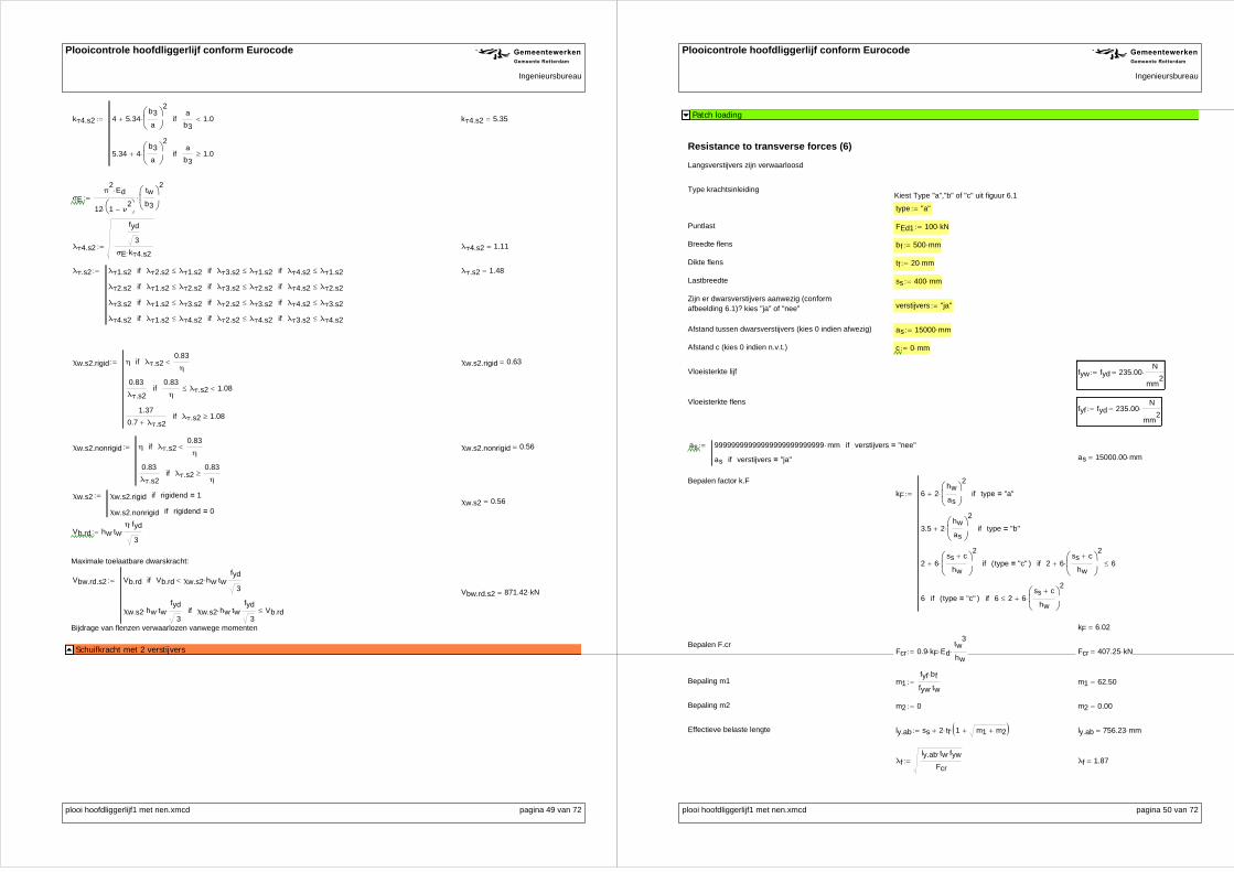
Plooicontrole hoofdliggerlijf conform Eurocode R GIngenieursbureau
kτ4.s2 4 5.34b3
a
2
a
b31.0if
5.34 4b3
a
2
a
b31.0if
kτ4.s2 5.35
σEπ
2Ed
12 1 ν2
tw
b3
2
λτ4.s2
fyd
3
σE kτ4.s2 λτ4.s2 1.11
λτ.s2 λτ1.s2 λτ2.s2 λτ1.s2if λτ3.s2 λτ1.s2if λτ4.s2 λτ1.s2if
λτ2.s2 λτ1.s2 λτ2.s2if λτ3.s2 λτ2.s2if λτ4.s2 λτ2.s2if
λτ3.s2 λτ1.s2 λτ3.s2if λτ2.s2 λτ3.s2if λτ4.s2 λτ3.s2if
λτ4.s2 λτ1.s2 λτ4.s2if λτ2.s2 λτ4.s2if λτ3.s2 λτ4.s2if
λτ.s2 1.48
χw.s2.rigid η λτ.s20.83
ηif
0.83
λτ.s2
0.83
ηλτ.s2 1.08if
1.37
0.7 λτ.s2λτ.s2 1.08if
χw.s2.rigid 0.63
χw.s2.nonrigid η λτ.s20.83
ηif
0.83
λτ.s2λτ.s2
0.83
ηif
χw.s2.nonrigid 0.56
χw.s2 χw.s2.rigid rigidend 1=if
χw.s2.nonrigid rigidend 0=if
χw.s2 0.56
Vb.rd hw twη fyd
3
Maximale toelaatbare dwarskracht:
Vbw.rd.s2 Vb.rd Vb.rd χw.s2 hw twfyd
3if
χw.s2 hw twfyd
3 χw.s2 hw tw
fyd
3 Vb.rdif
Vbw.rd.s2 871.42 kN
Bijdrage van flenzen verwaarlozen vanwege momenten
Schuifkracht met 2 verstijvers
plooi hoofdliggerlijf1 met nen.xmcd pagina 49 van 72
Plooicontrole hoofdliggerlijf conform Eurocode R GIngenieursbureau
Patch loading
Resistance to transverse forces (6)
Langsverstijvers zijn verwaarloosd
Type krachtsinleidingKiest Type "a","b" of "c" uit figuur 6.1
type "a"
Puntlast FEd1 100 kN
Breedte flens bf 500 mm
Dikte flens tf 20 mm
Lastbreedte ss 400 mm
Zijn er dwarsverstijvers aanwezig (conformafbeelding 6.1)? kies "ja" of "nee" verstijvers "ja"
Afstand tussen dwarsverstijvers (kies 0 indien afwezig) as 15000 mm
Afstand c (kies 0 indien n.v.t.) c 0 mm
Vloeisterkte lijf fyw fyd 235.00N
mm2
Vloeisterkte flensfyf fyd 235.00
N
mm2
as 99999999999999999999999999 mm verstijvers "nee"=if
as verstijvers "ja"=if
as 15000.00 mm
Bepalen factor k.F
kF 6 2hw
as
2
type "a"=if
3.5 2hw
as
2
type "b"=if
2 6ss c
hw
2
type "c"=( )if 2 6ss c
hw
2
6if
6 type "c"=( )if 6 2 6ss c
hw
2
if
kF 6.02
Bepalen F.crFcr 0.9 kF Ed
tw3
hw Fcr 407.25 kN
Bepaling m1 m1fyf bf
fyw tw m1 62.50
Bepaling m2 m2 0 m2 0.00
Effectieve belaste lengte ly.ab ss 2 tf 1 m1 m2 ly.ab 756.23 mm
λfly.ab tw fyw
Fcr λf 1.87
plooi hoofdliggerlijf1 met nen.xmcd pagina 50 van 72

Plooicontrole hoofdliggerlijf conform Eurocode R GIngenieursbureau
m2 0 λf 0.5if
0.02hw
tf
2
λf 0.5if
Verificatie m2 m2 102.25
ly.ab ss 2 tf 1 m1 m2 ly.ab 953.41 mmEffectieve belaste lengte type a of b
lekF Ed tw
2
2 fyw hw
kF Ed tw2
2 fyw hwss c if
ss c ss c kF Ed tw
2
2 fyw hwif
le 120.35 mm
Bepaling m1 m1fyf bf
fyw tw m1 62.50
Bepaling m2 m2 0 m2 0.00
Effectieve belaste lengte ly.c1 le tfm1
2
le
tf
2
m2 ly.c1 284.61 mm
λfly.c1 tw fyw
Fcr λf 1.15
m2 0 λf 0.5if
0.02hw
tf
2
λf 0.5if
Verificatie m2 m2 102.25
ly.c1 le tfm1
2
le
tf
2
m2 ly.c1 380.89 mmEffectieve belaste lengte type c1
Bepaling m1 m1fyf bf
fyw tw m1 62.50
Bepaling m2 m2 0 m2 0.00
Effectieve belaste lengte ly.c2 le tf m1 m2 ly.c2 278.46 mm
λfly.c2 tw fyw
Fcr λf 1.13
m2 0 λf 0.5if
0.02hw
tf
2
λf 0.5if
Verificatie m2 m2 102.25
ly.c2 le tf m1 m2 ly.c2 377.05 mmEffectieve belaste lengte type c2
ly ly.ab type "a"=if
ly.ab type "b"=if
ly.ab type "c"=if ly.ab ly.c1if ly.ab ly.c2if
ly.c1 type "c"=if ly.c1 ly.abif ly.c1 ly.c2if
ly.c2 type "c"=if ly.c2 ly.c1if ly.c2 ly.abif
plooi hoofdliggerlijf1 met nen.xmcd pagina 51 van 72
Plooicontrole hoofdliggerlijf conform Eurocode R GIngenieursbureau
ly 953.41 mm
λfly tw fyw
Fcr
λf 2.10
Reductiefactor voor lokaal plooienχF
0.5
λf
0.5
λf1if
1 otherwise
χF 0.24
Effectieve lengte Leff χF ly Leff 227.23 mm
Ontwerpsterkte voor lokaal plooienFRd
fyw Leff tw γM1
FRd 427.19 kN
Verficatie η2 ucFEd1
fyw Leff tw
γM1
uc 0.23
Controle "ok" uc 1if
"niet ok" otherwise
Controle "ok"
Patch loading
plooi hoofdliggerlijf1 met nen.xmcd pagina 52 van 72

Plooicontrole hoofdliggerlijf conform Eurocode R GIngenieursbureau
ULS Toets:
Rekenwaarde dwarsbelasting: Fed 100 kN Dwarsbelasting positief!
Rekenwaarde dwarskracht: Ved 200 kN Dwarskracht positief!
Rekenwaarde axiale druk: Ned 9000 kN Druk positief !
Rekenwaarde buigend moment: Med 3000 kN mAltijd positief invullen! Druk boven! (zo niet, profiel spiegelen)
NEN6771 toetsing lijf (0 verstijvingen)
NEN6771 toetsing lijf (1 verstijvingen)
NEN6771 toetsing lijf (2 verstijvingen)
plooi hoofdliggerlijf1 met nen.xmcd pagina 53 van 72
Plooicontrole hoofdliggerlijf conform Eurocode R GIngenieursbureau
ULS Toets
Kiezen correcte oppervlakte, zwaartepunt, traagheidsmoment
Effectieve oppervlakte voor axiale druk:
Aa.eff Aa0.eff verstijving1 0=if
Aa1.eff verstijving1 1=if
Aa2.eff verstijving2 1=if
Aa.eff 71288.77 mm
2
Aa.eff Atot Ned 0if
Aa.eff Ned 0if
Aa.eff 71288.77 mm2
Effectief zwaartepunt voor axiale druk:
eb.a.eff eb.a0.eff verstijving1 0=if
eb.a1.eff verstijving1 1=if
eb.a2.eff verstijving2 1=if
eb.a.eff 570.07 mm
Bruto zwaartepunt voor axiale druk:
eb.a eb.a0 verstijving1 0=if
eb.a1 verstijving1 1=if
eb.a2 verstijving2 1=if
eb.a 592.52 mm
Verschuiving zwaartepunt voor axiale druk:
Δea eb.a.eff eb.aΔea 22.46 mm
Δea 0 Δea 0if Ned 0if
0 Δea 0if Ned 0if
Δea Δea 0if Ned 0if
Δea Δea 0if Ned 0if
Δea 0.00 mm
Verstijving 1 in trekzone voor moment:
trek1 0 eb hv1if
1 otherwise
trek1 0.00
Verstijving 2 in trekzone voor moment:
trek2 0 eb hv2if
1 otherwise
trek2 1.00
Iy.m0.eff 3.45 1010
mm4
Iy.m1.eff Iy.m0.eff trek1 1=if
Iy.m1.eff otherwise
Iy.m1.eff 3.46 1010
mm4
Iy.m2.eff Iy.m1.eff trek2 1=if
Iy.m2.eff otherwise
Iy.m2.eff 3.46 1010
mm4
Effectief traagheidsmoment voor moment:
Iy.m.eff Iy.m0.eff verstijving1 0=if
Iy.m1.eff verstijving1 1=if
Iy.m2.eff verstijving2 1=if
Iy.m.eff 3.46 10
10 mm
4
eb.m0.eff 593.88 mm
eb.m1.eff eb.m0.eff trek1 1=if
eb.m1.eff otherwise
eb.m1.eff 592.52 mm
eb.m2.eff eb.m1.eff trek2 1=if
eb.m2.eff otherwise
eb.m2.eff 592.52 mm
plooi hoofdliggerlijf1 met nen.xmcd pagina 54 van 72

Plooicontrole hoofdliggerlijf conform Eurocode R GIngenieursbureau
Effectief zwaartepunt voor moment:
eb.m.eff eb.m0.eff verstijving1 0=if
eb.m1.eff verstijving1 1=if
eb.m2.eff verstijving2 1=if
eb.m.eff 592.52 mm
Effectieve afstand tot uiterste vezel voor moment:
zmax eb.m.eff eb.m.eff ht eb.m.effif
ht eb.m.eff otherwise
zmax 907.48 mm
Maximale dwarskracht voor plooi:
Vbw.rd Vbw.rd.s0 verstijving1 0=if
Vbw.rd.s1 verstijving1 1=if
Vbw.rd.s2 verstijving2 1=if
Vbw.rd 834.08 kN
Toetsing axiale druk en moment:
η1.1Ned
fyd Aa.eff
γM0
Med Ned Δea
fydIy.m.eff
eb.m.eff
γM0
η1.1 0.76
η1.2Ned
fyd Aa.eff
γM0
Med Ned Δea
fydIy.m.eff
ht eb.m.eff
γM0
η1.2 0.20
Toetsing axiale spanning:
η1 η1.1 η1.1 η1.2if
η1.2 η1.2 η1.1if
η1 0.76
Toetsing maximale dwarsbelasting
η2Fed
FRd η2 0.23
Toetsing maximale dwarskracht:
η3Ved
Vbw.rd η3 0.24
ULS Toets
Individuele toetsing: Interactie toetsing:
η1 0.76 Toets <1.0
Formule 7.1 η1 2 η3 1 2 1.03 Toets <1.0 Alleen toepassen als η3>0.5η2 0.23 Toets <1.0
Formule 7.2 η2 0.8 η1 0.84 Toets <1.4η3 0.24 Toets <1.0
Formule 2.94volgens Beg et. al η3 1
Fed
2 Ved
1.6
η2 0.30 Toets <1.0
plooi hoofdliggerlijf1 met nen.xmcd pagina 55 van 72
Plooicontrole hoofdliggerlijf conform Eurocode R GIngenieursbureau
Toetsing van het profiel op basis van reductie van het lijf op basis van gereduceerde spanningenmethode:
Mk Med
Vk Ved
Nk Ned
SLS Zonder verstijver
Reduced stress method for web (10)
σx1.kMk
Iye2
Nk
Atot
σx1.k 164.24N
mm2
σx2.kMk
Iye4
Nk
Atot
σx2.k 40.11N
mm2
τkVk
hw tw τk 17.48
N
mm2
Ψxσx2.k
σx1.k Ψx 0.24
kx 4 Ψx 1=if
8.2
1.05 Ψx 0 Ψx 1if
7.8 Ψx 0=if
7.81 6.29 Ψx 9.78 Ψx2
0 Ψx 1if
23.9 Ψx 1=if
5.98 1 Ψx 2 1 Ψx 3if
95.68 Ψx 3if
kx 6.34
σx.cr kxπ
2Ed
12 1 ν2
tw
hw
2
σx.cr 37.64N
mm2
αcr.xσx.cr
σx1.k αcr.x 0.23
kτ 5.34 4hw
a
2
a
hw1if
4 5.34hw
a
2
a
hw1if
kτ 5.38
τcr kτ
π2
Ed
12 1 ν2
tw
hw
2
τcr 31.94N
mm2
αcr.ττcr
τk αcr.τ 1.83
σeq.k σx1.k2
3 τk2
σeq.k 167.01N
mm2
plooi hoofdliggerlijf1 met nen.xmcd pagina 56 van 72

Plooicontrole hoofdliggerlijf conform Eurocode R GIngenieursbureau
αult.kfyd
σeq.k αult.k 1.41
αcr1
1 Ψx
4 αcr.x
1 Ψx
4 αcr.x
21 Ψx
2 αcr.x2
1
αcr.τ2
αcr 0.23
λpαult.k
αcr
λp 2.49
x richting:
σx.cbπ
2Ed tw
2
12 1 ν2
a2
λcxσx1.k
σx.cb
Φcx 0.5 1 0.21 λcx 0.2 λcx2
χcx 1 11
Φcx Φcx2
λcx2
if
1
Φcx Φcx2
λcx2
otherwise
χcx 0.00
αc.crit.xσx.cb
σx1.k
ρx.p 1 λp 0.5 0.085 0.055 Ψxif
λp 0.055 3 Ψx
λp2
otherwise
ρx.p 0.37
ξx 1αcr
αc.crit.x1 1if
0 0αcr
αc.crit.x1if
αcr
αc.crit.x1 otherwise
ξx 1.00
ρx ρx.p χcx ξx 2 ξx χcx ρx 0.37
Schuifkracht :
χw.rigid η λp0.83
ηif
0.83
λpotherwise
1.37
0.7 λpλp 1.08if
χw.rigid 0.43
plooi hoofdliggerlijf1 met nen.xmcd pagina 57 van 72
Plooicontrole hoofdliggerlijf conform Eurocode R GIngenieursbureau
χw.nonrigid η λp0.83
ηif
0.83
λpotherwise
χw.nonrigid 0.33
χw χw.nonrigid rigidend 0=if
χw.rigid otherwise
χw 0.33
Toets :
usls.0σx1.k
ρx fyd
2
3τk
χw fyd
2
usls.0 1.92
SLS Zonder verstijver
SLS met 1 verstijver
Reduced stress method for web (10)
Bovenkant tot verstijver 1:
h1 360.00 mm
h2 300.00 mm
h3 770.00 mm
σx1.kMk
Iye2
Nk
Atot
σx1.k 164.24N
mm2
σx2.kMk
Iyev1
Nk
Atot
σx2.k 132.99N
mm2
τkVk
hw tw τk 17.48
N
mm2
Ψxσx2.k
σx1.k Ψx 0.81
kx 4 Ψx 1=if
8.2
1.05 Ψx 0 Ψx 1if
7.8 Ψx 0=if
7.81 6.29 Ψx 9.78 Ψx2
0 Ψx 1if
23.9 Ψx 1=if
5.98 1 Ψx 2 1 Ψx 3if
95.68 Ψx 3if
kx 4.41
σx.cr kxπ
2Ed
12 1 ν2
tw
h1
2
σx.cr 413.27N
mm2
plooi hoofdliggerlijf1 met nen.xmcd pagina 58 van 72

Plooicontrole hoofdliggerlijf conform Eurocode R GIngenieursbureau
αcr.xσx.cr
σx1.k αcr.x 2.52
kτ 5.34 4h1
a
2
a
h11if
4 5.34h1
a
2
a
h11if
kτ 5.34
τcr kτ
π2
Ed
12 1 ν2
tw
h1
2
τcr 500.73N
mm2
αcr.ττcr
τk αcr.τ 28.64
σeq.k σx1.k2
3 τk2
σeq.k 167.01N
mm2
αult.kfyd
σeq.k αult.k 1.41
αcr1
1 Ψx
4 αcr.x
1 Ψx
4 αcr.x
21 Ψx
2 αcr.x2
1
αcr.τ2
αcr 2.50
λpαult.k
αcr
λp 0.75
x richting:
σx.cbπ
2Ed tw
2
12 1 ν2
a2
λcxσx1.k
σx.cb
Φcx 0.5 1 0.21 λcx 0.2 λcx2
χcx 1 11
Φcx Φcx2
λcx2
if
1
Φcx Φcx2
λcx2
otherwise
χcx 0.00
αc.crit.xσx.cb
σx1.k
ρx.p 1 λp 0.5 0.085 0.055 Ψxif
λp 0.055 3 Ψx
λp2
otherwise
ρx.p 0.96
plooi hoofdliggerlijf1 met nen.xmcd pagina 59 van 72
Plooicontrole hoofdliggerlijf conform Eurocode R GIngenieursbureau
ξx 1αcr
αc.crit.x1 1if
0 0αcr
αc.crit.x1if
αcr
αc.crit.x1 otherwise
ξx 1.00
ρx ρx.p χcx ξx 2 ξx χcx ρx 0.96
Schuifkracht :
χw.rigid η λp0.83
ηif
0.83
λpotherwise
1.37
0.7 λpλp 1.08if
χw.rigid 1.11
χw.nonrigid η λp0.83
ηif
0.83
λpotherwise
χw.nonrigid 1.11
χw χw.nonrigid rigidend 0=if
χw.rigid otherwise
χw 1.11
Toets :
usls.1.1σx1.k
ρx fyd
2
3τk
χw fyd
2
usls.1.1 0.74
Verstijver 1 tot onderkant:
h1 360.00 mm
h2 300.00 mm
h3 770.00 mm
σx1.kMk
Iyev1
Nk
Atot
σx1.k 132.99N
mm2
σx2.kMk
Iye4
Nk
Atot
σx2.k 40.11N
mm2
τkVk
hw tw τk 17.48
N
mm2
Ψx 1σx2.k
σx1.k1if
σx2.k
σx1.kotherwise
Ψx 0.30
plooi hoofdliggerlijf1 met nen.xmcd pagina 60 van 72

Plooicontrole hoofdliggerlijf conform Eurocode R GIngenieursbureau
kx 4 Ψx 1=if
8.2
1.05 Ψx 0 Ψx 1if
7.8 Ψx 0=if
7.81 6.29 Ψx 9.78 Ψx2
0 Ψx 1if
23.9 Ψx 1=if
5.98 1 Ψx 2 1 Ψx 3if
95.68 Ψx 3if
kx 6.07
σx.cr kxπ
2Ed
12 1 ν2
tw
h2 h3
2
σx.cr 64.37N
mm2
αcr.xσx.cr
σx1.k αcr.x 0.48
kτ 5.34 4h2 h3
a
2
a
h2 h31if
4 5.34h2 h3
a
2
a
h2 h31if
kτ 5.36
τcr kτ
π2
Ed
12 1 ν2
tw
h2 h3
2
τcr 56.87N
mm2
αcr.ττcr
τk αcr.τ 3.25
σeq.k σx1.k2
3 τk2
σeq.k 136.40N
mm2
αult.kfyd
σeq.k αult.k 1.72
αcr1
1 Ψx
4 αcr.x
1 Ψx
4 αcr.x
21 Ψx
2 αcr.x2
1
αcr.τ2
αcr 0.48
λpαult.k
αcr
λp 1.90
x richting:
σx.cbπ
2Ed tw
2
12 1 ν2
a2
λcxσx1.k
σx.cb
Φcx 0.5 1 0.21 λcx 0.2 λcx2
plooi hoofdliggerlijf1 met nen.xmcd pagina 61 van 72
Plooicontrole hoofdliggerlijf conform Eurocode R GIngenieursbureau
χcx 1 11
Φcx Φcx2
λcx2
if
1
Φcx Φcx2
λcx2
otherwise
χcx 0.00
αc.crit.xσx.cb
σx1.k
ρx.p 1 λp 0.5 0.085 0.055 Ψxif
λp 0.055 3 Ψx
λp2
otherwise
ρx.p 0.48
ξx 1αcr
αc.crit.x1 1if
0 0αcr
αc.crit.x1if
αcr
αc.crit.x1 otherwise
ξx 1.00
ρx ρx.p χcx ξx 2 ξx χcx ρx 0.48
Schuifkracht :
χw.rigid η λp0.83
ηif
0.83
λpotherwise
1.37
0.7 λpλp 1.08if
χw.rigid 0.53
χw.nonrigid η λp0.83
ηif
0.83
λpotherwise
χw.nonrigid 0.44
χw χw.nonrigid rigidend 0=if
χw.rigid otherwise
χw 0.44
Toets :
usls.1.2σx1.k
ρx fyd
2
3τk
χw fyd
2
usls.1.2 1.23
usls.1 usls.1.1 usls.1.2 usls.1.1if
usls.1.2 usls.1.1 usls.1.2if
usls.1 1.23
SLS met 1 verstijver
SLS met 2 verstijvers
Reduced stress method for web (10)Bovenkant tot verstijver 1:
plooi hoofdliggerlijf1 met nen.xmcd pagina 62 van 72

Plooicontrole hoofdliggerlijf conform Eurocode R GIngenieursbureau
h1 360.00 mm
h2 300.00 mm
h3 770.00 mm
σx1.kMk
Iye2
Nk
Atot
σx1.k 164.24N
mm2
σx2.kMk
Iyev1
Nk
Atot
σx2.k 132.99N
mm2
τkVk
hw tw
τk 17.48N
mm2
Ψxσx2.k
σx1.k Ψx 0.81
kx 4 Ψx 1=if
8.2
1.05 Ψx 0 Ψx 1if
7.8 Ψx 0=if
7.81 6.29 Ψx 9.78 Ψx2
0 Ψx 1if
23.9 Ψx 1=if
5.98 1 Ψx 2 1 Ψx 3if
95.68 Ψx 3if
kx 4.41
σx.cr kxπ
2Ed
12 1 ν2
tw
h1
2
σx.cr 413.27N
mm2
αcr.xσx.cr
σx1.k αcr.x 2.52
kτ 5.34 4h1
a
2
a
h11if
4 5.34h1
a
2
a
h11if
kτ 5.34
τcr kτ
π2
Ed
12 1 ν2
tw
h1
2
τcr 500.73N
mm2
αcr.ττcr
τk αcr.τ 28.64
σeq.k σx1.k2
3 τk2
σeq.k 167.01N
mm2
αult.kfyd
σeq.k αult.k 1.41
αcr1
1 Ψx
4 αcr.x
1 Ψx
4 αcr.x
21 Ψx
2 αcr.x2
1
αcr.τ2
αcr 2.50
λpαult.k
αcr
λp 0.75
x richting:
plooi hoofdliggerlijf1 met nen.xmcd pagina 63 van 72
Plooicontrole hoofdliggerlijf conform Eurocode R GIngenieursbureau
σx.cbπ
2Ed tw
2
12 1 ν2
a2
λcxσx1.k
σx.cb
Φcx 0.5 1 0.21 λcx 0.2 λcx2
χcx 1 11
Φcx Φcx2
λcx2
if
1
Φcx Φcx2
λcx2
otherwise
χcx 0.00
αc.crit.xσx.cb
σx1.k
ρx.p 1 λp 0.5 0.085 0.055 Ψxif
λp 0.055 3 Ψx
λp2
otherwise
ρx.p 0.96
ξx 1αcr
αc.crit.x1 1if
0 0αcr
αc.crit.x1if
αcr
αc.crit.x1 otherwise
ξx 1.00
ρx ρx.p χcx ξx 2 ξx χcx ρx 0.96Schuifkracht :
χw.rigid η λp0.83
ηif
0.83
λpotherwise
1.37
0.7 λpλp 1.08if
χw.rigid 1.11
χw.nonrigid η λp0.83
ηif
0.83
λpotherwise
χw.nonrigid 1.11
χw χw.nonrigid rigidend 0=if
χw.rigid otherwise
χw 1.11
Toets :
usls.2.1σx1.k
ρx fyd
2
3τk
χw fyd
2
usls.2.1 0.74
Verstijver 1 tot verstijver 2:
h1 360.00 mm
h2 300.00 mm
h3 770.00 mm
σx1.kMk
Iyev1
Nk
Atot
σx1.k 132.99N
mm2
plooi hoofdliggerlijf1 met nen.xmcd pagina 64 van 72

Plooicontrole hoofdliggerlijf conform Eurocode R GIngenieursbureau
σx2.kMk
Iyev2
Nk
Atot
σx2.k 106.95N
mm2
τkVk
hw tw τk 17.48
N
mm2
Ψx 1σx2.k
σx1.k1if
σx2.k
σx1.kotherwise
Ψx 0.80
kx 4 Ψx 1=if
8.2
1.05 Ψx 0 Ψx 1if
7.8 Ψx 0=if
7.81 6.29 Ψx 9.78 Ψx2
0 Ψx 1if
23.9 Ψx 1=if
5.98 1 Ψx 2 1 Ψx 3if
95.68 Ψx 3if
kx 4.42
σx.cr kxπ
2Ed
12 1 ν2
tw
h2
2
σx.cr 596.89N
mm2
αcr.xσx.cr
σx1.k αcr.x 4.49
kτ 5.34 4h2
a
2
a
h21if
4 5.34h2
a
2
a
h21if
kτ 5.34
τcr kτ
π2
Ed
12 1 ν2
tw
h2
2
τcr 720.95N
mm2
αcr.ττcr
τk αcr.τ 41.24
σeq.k σx1.k2
3 τk2
σeq.k 136.40N
mm2
αult.kfyd
σeq.k αult.k 1.72
αcr1
1 Ψx
4 αcr.x
1 Ψx
4 αcr.x
21 Ψx
2 αcr.x2
1
αcr.τ2
αcr 4.44
λpαult.k
αcr
λp 0.62
x richting:
σx.cbπ
2Ed tw
2
12 1 ν2
a2
λcxσx1.k
σx.cb
plooi hoofdliggerlijf1 met nen.xmcd pagina 65 van 72
Plooicontrole hoofdliggerlijf conform Eurocode R GIngenieursbureau
Φcx 0.5 1 0.21 λcx 0.2 λcx2
χcx 1 11
Φcx Φcx2
λcx2
if
1
Φcx Φcx2
λcx2
otherwise
χcx 0.00
αc.crit.xσx.cb
σx1.k
ρx.p 1 λp 0.5 0.085 0.055 Ψxif
λp 0.055 3 Ψx
λp2
otherwise
ρx.p 1.00
ξx 1αcr
αc.crit.x1 1if
0 0αcr
αc.crit.x1if
αcr
αc.crit.x1 otherwise
ξx 1.00
ρx ρx.p χcx ξx 2 ξx χcx ρx 1.00
Schuifkracht :
χw.rigid η λp0.83
ηif
0.83
λpotherwise
1.37
0.7 λpλp 1.08if
χw.rigid 1.20
χw.nonrigid η λp0.83
ηif
0.83
λpotherwise
χw.nonrigid 1.20
χw χw.nonrigid rigidend 0=if
χw.rigid otherwise
χw 1.20
Toets :
usls.2.2σx1.k
ρx fyd
2
3τk
χw fyd
2
usls.2.2 0.58
Verstijver 2 tot onderkant:
h1 360.00 mm
h2 300.00 mm
h3 770.00 mm
σx1.kMk
Iyev2
Nk
Atot
σx1.k 106.95N
mm2
σx2.kMk
Iye4
Nk
Atot
σx2.k 40.11N
mm2
τkVk
hw tw τk 17.48
N
mm2
plooi hoofdliggerlijf1 met nen.xmcd pagina 66 van 72

Plooicontrole hoofdliggerlijf conform Eurocode R GIngenieursbureau
Ψx 1σx2.k
σx1.k1if
σx2.k
σx1.kotherwise
Ψx 0.38
kx 4 Ψx 1=if
8.2
1.05 Ψx 0 Ψx 1if
7.8 Ψx 0=if
7.81 6.29 Ψx 9.78 Ψx2
0 Ψx 1if
23.9 Ψx 1=if
5.98 1 Ψx 2 1 Ψx 3if
95.68 Ψx 3if
kx 5.75
σx.cr kxπ
2Ed
12 1 ν2
tw
h3
2
σx.cr 117.89N
mm2
αcr.xσx.cr
σx1.k αcr.x 1.10
kτ 5.34 4h3
a
2
a
h31if
4 5.34h3
a
2
a
h31if
kτ 5.35
τcr kτ
π2
Ed
12 1 ν2
tw
h3
2
τcr 109.62N
mm2
αcr.ττcr
τk αcr.τ 6.27
σeq.k σx1.k2
3 τk2
σeq.k 111.15N
mm2
αult.kfyd
σeq.k αult.k 2.11
αcr1
1 Ψx
4 αcr.x
1 Ψx
4 αcr.x
21 Ψx
2 αcr.x2
1
αcr.τ2
αcr 1.08
λpαult.k
αcr λp 1.40
x richting:
σx.cbπ
2Ed tw
2
12 1 ν2
a2
λcxσx1.k
σx.cb
Φcx 0.5 1 0.21 λcx 0.2 λcx2
χcx 1 11
Φcx Φcx2
λcx2
if
1
Φcx Φcx2
λcx2
otherwise
χcx 0.00
plooi hoofdliggerlijf1 met nen.xmcd pagina 67 van 72
Plooicontrole hoofdliggerlijf conform Eurocode R GIngenieursbureau
αc.crit.xσx.cb
σx1.k
ρx.p 1 λp 0.5 0.085 0.055 Ψxif
λp 0.055 3 Ψx
λp2
otherwise
ρx.p 0.62
ξx 1αcr
αc.crit.x1 1if
0 0αcr
αc.crit.x1if
αcr
αc.crit.x1 otherwise
ξx 1.00
ρx ρx.p χcx ξx 2 ξx χcx ρx 0.62Schuifkracht :
χw.rigid η λp0.83
ηif
0.83
λpotherwise
1.37
0.7 λpλp 1.08if
χw.rigid 0.65
χw.nonrigid η λp0.83
ηif
0.83
λpotherwise
χw.nonrigid 0.59
χw χw.nonrigid rigidend 0=if
χw.rigid otherwise
χw 0.59
Toets :
usls.2.3σx1.k
ρx fyd
2
3τk
χw fyd
2
usls.2.3 0.77
usls.2 usls.2.1 usls.2.2 usls.2.1if usls.2.3 usls.2.1if
usls.2.2 usls.2.1 usls.2.2if usls.2.3 usls.2.2if
usls.2.3 usls.2.1 usls.2.3if usls.2.2 usls.2.3if
usls.2 0.77
SLS met 2 verstijvers
usls.1 usls.0 trek1 1=if
usls.1 otherwise
Indien 0 verstijvers: usls.0 1.92usls.2 usls.1 trek2 1=if
usls.2 otherwise
Indien 1 verstijver: usls.1 1.23Indien 2 verstijvers: usls.2 1.23
usls usls.0 verstijving1 0=if
usls.1 verstijving1 1=if
usls.2 verstijving2 1=if
Dus hier: usls 1.23
Toetsing Von Mises spanning:
plooi hoofdliggerlijf1 met nen.xmcd pagina 68 van 72

Plooicontrole hoofdliggerlijf conform Eurocode R GIngenieursbureau
usls.sp
Nk
Atot
Mk
Iye1
2
3Vk
hw tw
2
fyd2
Nk
Atot
Mk
Iye1
2
3Vk
hw tw
2
Nk
Atot
Mk
Iye5
2
3Vk
hw tw
2
if
Nk
Atot
Mk
Iye5
2
3Vk
hw tw
2
fyd2
Nk
Atot
Mk
Iye5
2
3Vk
hw tw
2
Nk
Atot
Mk
Iye1
2
3Vk
hw tw
2
if
usls.sp 0.73
plooi hoofdliggerlijf1 met nen.xmcd pagina 69 van 72
Plooicontrole hoofdliggerlijf conform Eurocode R GIngenieursbureau
Flange induced buckling
k 0.55
Flange induced buckling (8)Af bfoL tfoL bfoR tfoR bfoL tfoL bfoR tfoR bfbL tfbL bfbR tfbRif
bfbL tfbL bfbR tfbR bfbL tfbL bfbR tfbR bfoL tfoL bfoR tfoRif
UC
httfbmax
2
tfomax
2
tw
kEd
fyd
httfbmax
2
tfomax
2
tw
Af
UC 0.69 Toets <1,0
Flange induced buckling
plooi hoofdliggerlijf1 met nen.xmcd pagina 70 van 72

Plooicontrole hoofdliggerlijf conform Eurocode R GIngenieursbureau
Torsional stiffness (Stiffener 1)
Minimum requirements for longitudinal stiffeners (9.2.2)
IT.v11
3tv1
3 bv1
IT.v1 128053.33 mm4
Iy.v11
12tv1 bv1
3
Iy.v1 3201333.33 mm4
Iz.v1 32013.33 mm4
Ip.v1 Iy.v1 Iz.v1 tv1 bv1bv1
2
2
Ip.v1 12837346.67 mm
4
UC 5.3fyd
Ed
Ip.v1
IT.v1 UC 0.59 Toets <1,0. als het niet voldoet kan met de actuele spanning worden gerekend ipv de vloeispanning
volgens Beg, et al. Design of Plated Structures (p139)
σst1Ned
Aa.eff
Med
Iy.m.effeb.m.eff hv1
σst1 142.96N
mm2
UC 5.3σst1
Ed
Ip.v1
IT.v1 UC 0.36 Toets <1,0
Torsional stiffness (Stiffener 1)
Torsional stiffness (Stiffener 2)
Minimum requirements for longitudinal stiffeners (9.2.2)
IT.v21
3tv2
3 bv2 IT.v2 3.33 10
13 mm
4
Iy.v21
12tv2 bv2
3 Iy.v2 8.33 10
14 mm
4
Iz.v21
12tv2
3 bv2 Iz.v2 8.33 10
14 mm
4
Ip.v2 Iy.v2 Iz.v2 tv2 bv2bv2
2
2
Ip.v2 4.17 1013
mm4
UC 5.3fyd
Ed
Ip.v2
IT.v2 UC 0.01 Toets <1,0. als het niet voldoet kan met de actuele spanning worden gerekend ipv de vloeispanning
volgens Beg, et al. Design of Plated Structures (p139)
σst2Ned
Aa.eff
Med
Iy.m.effeb.m.eff hv2
σst2 116.92N
mm2
UC 5.3σst2
Ed
Ip.v2
IT.v2 UC 0.00 Toets <1,0
Torsional stiffness (Stiffener 2)
Iz.v11
12tv1
3 bv1
plooi hoofdliggerlijf1 met nen.xmcd pagina 71 van 72
Plooicontrole hoofdliggerlijf conform Eurocode R GIngenieursbureau
Controle langsverstijving volgens NEN6771
plooi hoofdliggerlijf1 met nen.xmcd pagina 72 van 72


