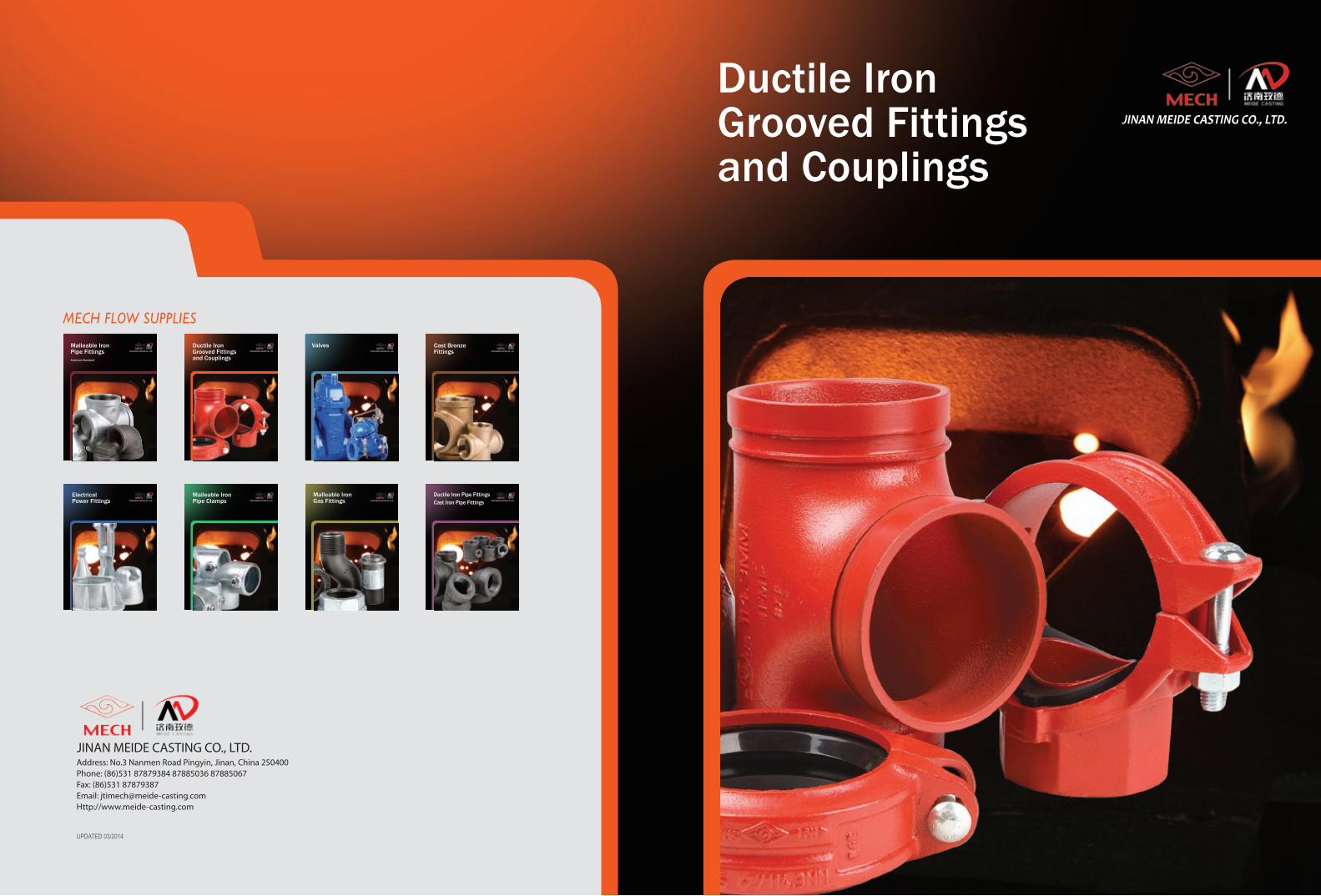
Ductile Iron Grooved Fittings and Couplings
Address: No.3 Nanmen Road Pingyin, Jinan, China 250400Phone: (86)531 87879384 87885036 87885067Fax: (86)531 87879387Email: [email protected]://www.meide-casting.com
UPDATED 03/2014
JINAN MEIDE CASTING CO., LTD.
American Standard
JINAN MEIDE CASTING CO., LTD.
Malleable Iron Pipe Fittings
Ductile Iron Pipe FittingsCast Iron Pipe Fittings JINAN MEIDE CASTING CO., LTD.
Ductile Iron Grooved Fittings and Couplings
JINAN MEIDE CASTING CO., LTD.
Electrical Power Fittings JINAN MEIDE CASTING CO., LTD.
ValvesJINAN MEIDE CASTING CO., LTD.
Malleable Iron Gas Fittings JINAN MEIDE CASTING CO., LTD.
Cast Bronze Fittings JINAN MEIDE CASTING CO., LTD.
Malleable Iron Pipe Clamps JINAN MEIDE CASTING CO., LTD.
MECH FLOW SUPPLIES
JINAN MEIDE CASTING CO., LTD.

More than 50 years of Foundry Experience
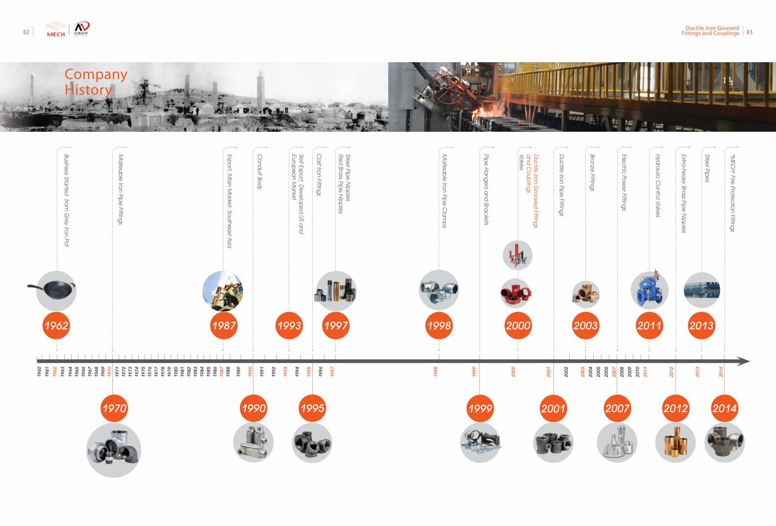
Company Profile
Jinan Meide Casting Co. Ltd. was established in 1962.
In the past decades, Jinan Meide has seized each
opportunity to consolidate its strength, and has finally
developed into what it is today, a large-scale enterprise
group with advanced technology, equipment and
strong comprehensive strength, known for its complete
range of products, large producing capacity, high
quality and strong R&D strength. The company owns
altogether one main factory, three branch factories, an
independent accounting steel pipe company, and a
science & technology park.
The company is the largest manufacturer in the fitting
industry with the most complete range of products,
supplying malleable iron fittings, grooved fittings,
grooved couplings, valves, cast iron fittings, ductile iron
fittings, steel pipe nipples and couplings, stainless steel
nipples, brass pipe nipples, cast bronze fittings, steel
pipes, pipe hangers and supports, electric fittings, etc.
Over 50 years, Jinan Meide has been a trusted name
in piping solutions by offering high-quality products,
service and support to the PVF industry continuously.
We provide expertise and product solutions for a wide
range of applications, plumbing, mechanical, industrial,
air-conditioning and refrigeration, mining, oil, gas, fire
protection, equipment and power system. Many of the
company’s application technology are advanced in the
world, with more than 20 patents registered each year,
and the company has presided over and participated in
the drafting of many important national standards of
the industry.
We organize the whole production process in
accordance with ISO 9001 and ISO 14001. It has also
the most complete certificates in the PVF industry,
including UL/FM/NSF of US, CRN/cUL of Canada,
DVGW/TUV/CE/VdS of Germany, BSI/LPCB of UK, SII of
Israel, JIS of Japan, ABNT of Brazil, GOST-R of Russia,
CNBOP of Poland, KS of South Korea, TSE of Turkey, PSB
of Singapore, SIRIM of Malaysia, SABS of South Africa
etc. The products are well distributed in more than 130
countries and regions.
As an industry leader and key high-tech enterprise of
the national torch plan, the company attaches great
importance to environmental protection, energy-
saving and emission-reduction. US-EEC recognizes
MECH brand malleable iron pipe fittings as “the
product to promote for the technology exchange of
environmental protection”. Protecting the environment
is the duty of the company.
Customer satisfaction has always been the company’s
top objective, and we constantly stick to the principle:
to provide customers with a value-added solution
rather than simply delivering products.
01Ductile Iron Grooved
Fittings and Couplings
Ma
llea
ble
Iron Pip
e Fitting
s
Ca
st Iron Fitting
s
Co
nduit Bo
dy
Pipe
Ha
nge
rs and
Brac
kets
Self Exp
ort, D
eve
lop
ed
US and
Euro
pe
an M
arke
t
Duc
tile Iro
n Gro
ove
d Fitting
s a
nd C
oup
lings
Valve
s
Bronze
Fittings
Hyd
raulic
Co
ntrol Va
lves
Extra-he
avy Bra
ss Pipe
Nip
ple
s
"MEC
H" Fire
Prote
ctio
n Fittings
Stee
l Pipe
s
Stee
l Pipe
Nip
ple
sRe
d Bra
ss Pipe
Nip
ple
s
Elec
tric Po
we
r Fittings
1960
1961
1962
1963
1964
1965
1966
1967
1968
1969
1970
1971
1972
1973
1974
1975
1976
1977
1978
1979
1980
1981
1982
1983
1984
1985
1986
1987
1988
1989
1990
1991
1992
1993
1994
1995
1996
1997
1998
1999
200
0
200
1
2002
2003
2004
2005
2006
2007
2008
2009
2010
2011
2012
201
3
2014
1970
19971993
2007 2012 2014
2000 2003 2011 2013
Expo
rt, Ma
in Ma
rket: So
uthea
st Asia
1987
Business Sta
rted
from
Gre
y Iron Po
t
1962M
alle
ab
le Iro
n Pipe
Cla
mp
s 1998
1990
Duc
tile Iro
n Pipe
Fittings
200119991995
CompanyHistory
0302Ductile Iron Grooved
Fittings and Couplings
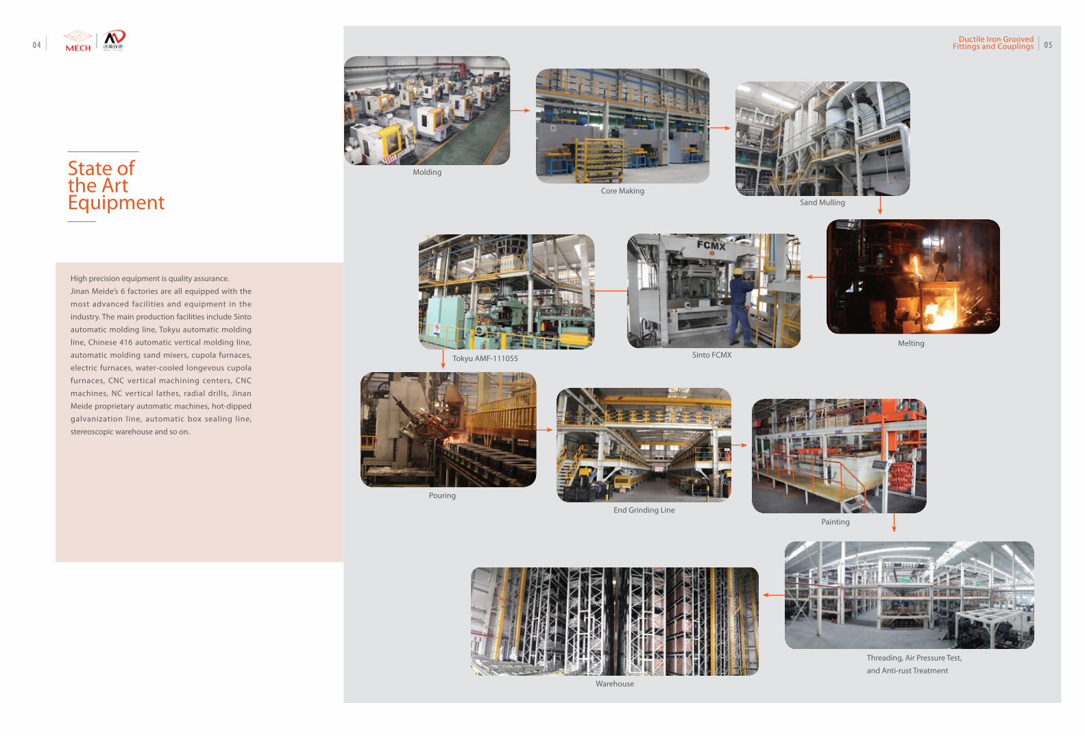
State ofthe Art Equipment
Molding
Core MakingSand Mulling
MeltingSinto FCMXTokyu AMF-111055
End Grinding LinePainting
Threading, Air Pressure Test,
and Anti-rust Treatment
Warehouse
Pouring
High precision equipment is quality assurance.
Jinan Meide’s 6 factories are all equipped with the
most advanced facilities and equipment in the
industry. The main production facilities include Sinto
automatic molding line, Tokyu automatic molding
line, Chinese 416 automatic vertical molding line,
automatic molding sand mixers, cupola furnaces,
electric furnaces, water-cooled longevous cupola
furnaces, CNC vertical machining centers, CNC
machines, NC vertical lathes, radial drills, Jinan
Meide proprietary automatic machines, hot-dipped
galvanization line, automatic box sealing line,
stereoscopic warehouse and so on.
0504Ductile Iron Grooved
Fittings and Couplings
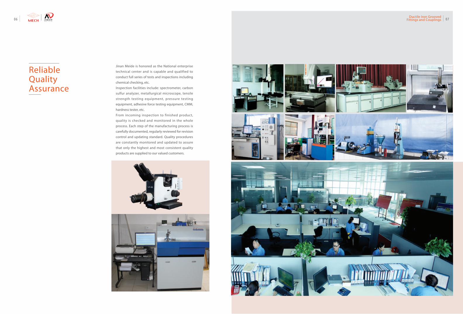
Reliable Quality Assurance
Jinan Meide is honored as the National enterprise
technical center and is capable and qualified to
conduct full series of tests and inspections including
chemical checking, etc.
Inspection facilities include: spectrometer, carbon
sulfur analyzer, metallurgical microscope, tensile
strength testing equipment, pressure testing
equipment, adhesive force testing equipment, CMM,
hardness tester, etc.
From incoming inspection to finished product,
quality is checked and monitored in the whole
process. Each step of the manufacturing process is
carefully documented, regularly reviewed for revision
control and updating standard. Quality procedures
are constantly monitored and updated to assure
that only the highest and most consistent quality
products are supplied to our valued customers.
0706Ductile Iron Grooved
Fittings and Couplings
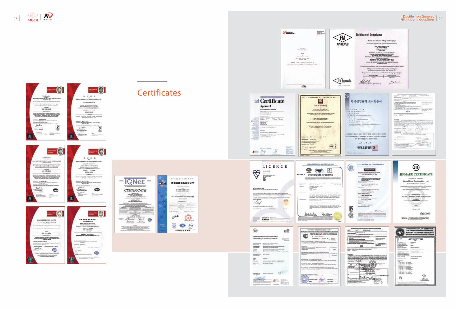
Certificates
0908Ductile Iron Grooved
Fittings and Couplings
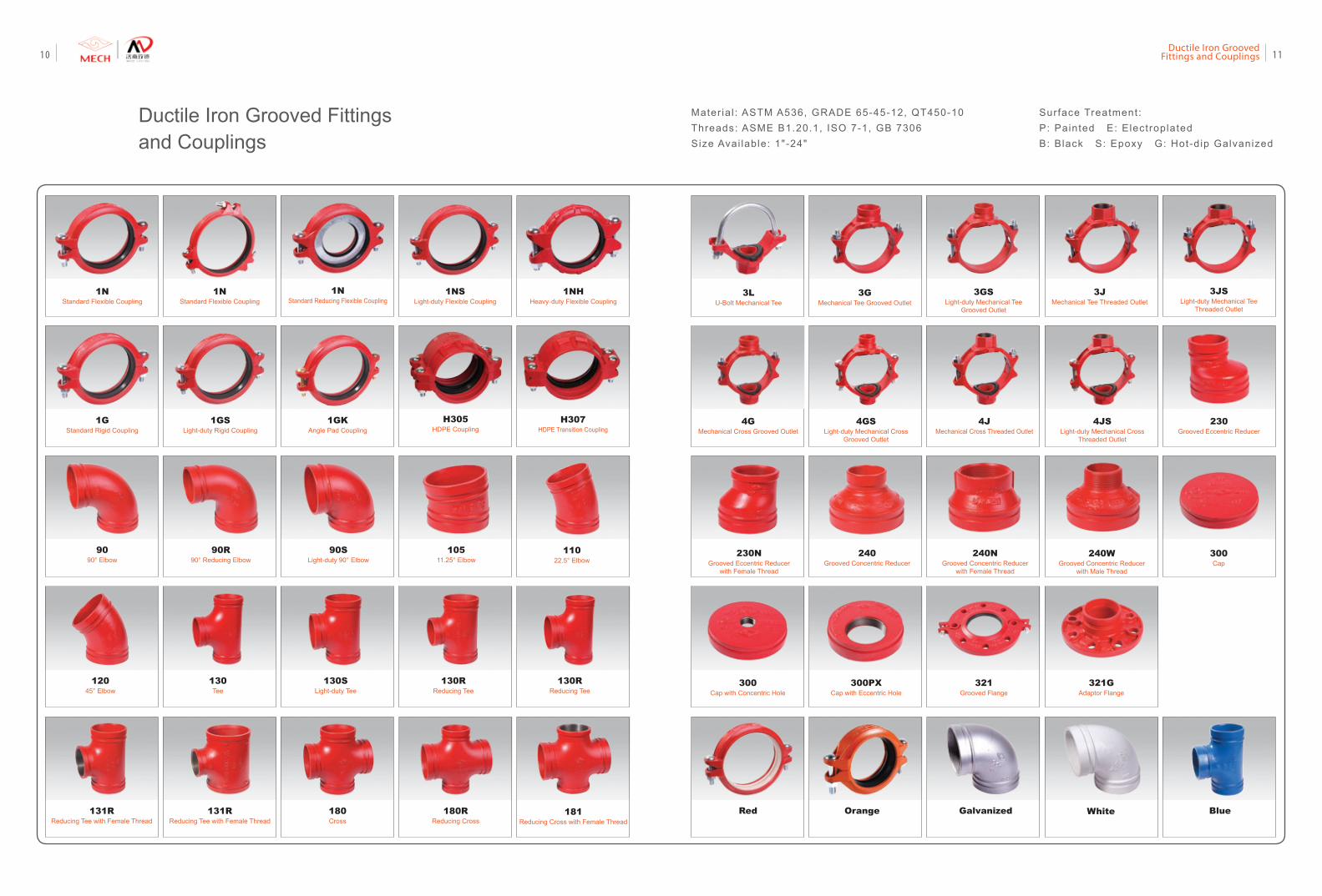
Ductile Iron Grooved Fittings and Couplings
Surface Treatment:P: Painted E: Electroplated B: Black S: Epoxy G: Hot-dip Galvanized
1NStandard Flexible Coupling
1NStandard Flexible Coupling
1NHHeavy-duty Flexible Coupling
1NStandard Reducing Flexible Coupling
1NSLight-duty Flexible Coupling
1GStandard Rigid Coupling
1GKAngle Pad Coupling
1GSLight-duty Rigid Coupling
9090° Elbow
90R90° Reducing Elbow
90SLight-duty 90° Elbow
10511.25° Elbow
11022.5° Elbow
12045° Elbow
130Tee
130SLight-duty Tee
130RReducing Tee
3GMechanical Tee Grooved Outlet
3GSLight-duty Mechanical Tee
Grooved Outlet
3JMechanical Tee Threaded Outlet
3JSLight-duty Mechanical Tee
Threaded Outlet
3LU-Bolt Mechanical Tee
4GMechanical Cross Grooved Outlet
4JMechanical Cross Threaded Outlet
4JSLight-duty Mechanical Cross
Threaded Outlet
230Grooved Eccentric Reducer
230NGrooved Eccentric Reducer
with Female Thread
240Grooved Concentric Reducer
240NGrooved Concentric Reducer
with Female Thread
300Cap
300Cap with Concentric Hole
300PXCap with Eccentric Hole
321Grooved Flange
321GAdaptor Flange
BlueRed WhiteGalvanizedOrange
240WGrooved Concentric Reducer
with Male Thread
180Cross
180RReducing Cross
130RReducing Tee
131RReducing Tee with Female Thread
131RReducing Tee with Female Thread
Mater ia l : ASTM A536, GRADE 65-45-12, QT450-10Threads: ASME B1.20.1, ISO 7-1, GB 7306Size Avai lable: 1"-24"
H305HDPE Coupling
H307HDPE Transition Coupling
181Reducing Cross with Female Thread
4GSLight-duty Mechanical Cross
Grooved Outlet
1110Ductile Iron Grooved
Fittings and Couplings
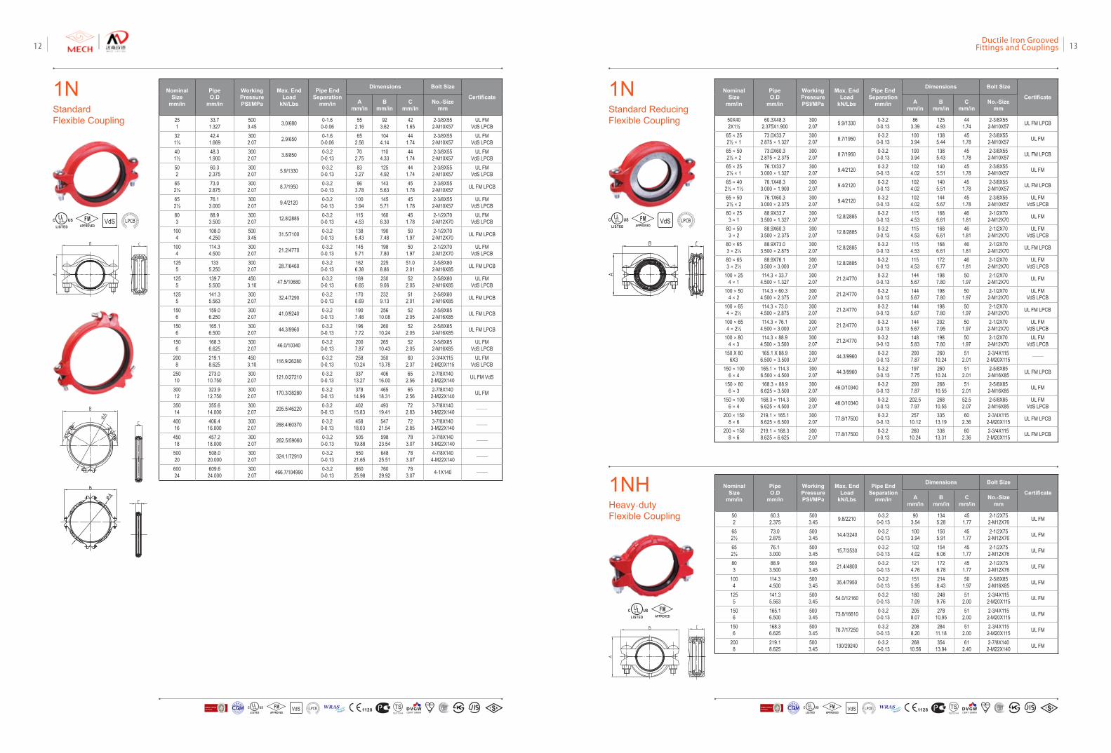
1NStandard Flexible Coupling
1NStandard Reducing Flexible Coupling
Nominal Size
mm/in
Pipe O.D
mm/in
Working PressurePSI/MPa
Max. End Load
kN/Lbs
Pipe End Separation
mm/in
Dimensions Bolt Size
CertificateA
mm/inB
mm/inC
mm/inNo.-Size
mm
251
33.71.327
5003.45 3.0/680 0-1.6
0-0.0655
2.1692
3.6242
1.652-3/8X55
2-M10X57UL FM
VdS LPCB321¼
42.41.669
3002.07 2.9/650 0-1.6
0-0.0665
2.561044.14
441.74
2-3/8X552-M10X57
UL FMVdS LPCB
401½
48.31.900
3002.07 3.8/850 0-3.2
0-0.1370
2.751104.33
441.74
2-3/8X552-M10X57
UL FMVdS LPCB
502
60.32.375
3002.07 5.9/1330 0-3.2
0-0.1383
3.271254.92
441.74
2-3/8X552-M10X57
UL FMVdS LPCB
652½
73.02.875
3002.07 8.7/1950 0-3.2
0-0.1396
3.781435.63
451.78
2-3/8X552-M10X57 UL FM LPCB
652½
76.13.000
3002.07 9.4/2120 0-3.2
0-0.131003.94
1455.71
451.78
2-3/8X552-M10X57
UL FMVdS LPCB
803
88.93.500
3002.07 12.8/2885 0-3.2
0-0.131154.53
1606.30
451.78
2-1/2X702-M12X70
UL FMVdS LPCB
1004
108.04.250
5003.45 31.5/7100 0-3.2
0-0.131385.43
1907.48
501.97
2-1/2X702-M12X70 UL FM LPCB
1004
114.34.500
3002.07 21.2/4770 0-3.2
0-0.131455.71
1987.80
501.97
2-1/2X702-M12X70
UL FMVdS LPCB
1255
1335.250
3002.07 28.7/6460 0-3.2
0-0.131626.38
2258.86
51.02.01
2-5/8X802-M16X85 UL FM LPCB
1255
139.75.500
4503.10 47.5/10680 0-3.2
0-0.131696.65
2309.06
522.05
2-5/8X802-M16X85
UL FMVdS LPCB
1255
141.35.563
3002.07 32.4/7290 0-3.2
0-0.131706.69
2329.13
512.01
2-5/8X802-M16X85 UL FM LPCB
1506
159.06.250
3002.07 41.0/9240 0-3.2
0-0.131907.48
25610.08
522.05
2-5/8X852-M16X85 UL FM LPCB
1506
165.16.500
3002.07 44.3/9960 0-3.2
0-0.131967.72
26010.24
522.05
2-5/8X852-M16X85 UL FM LPCB
1506
168.36.625
3002.07 46.0/10340 0-3.2
0-0.132007.87
26510.43
522.05
2-5/8X852-M16X85
UL FMVdS LPCB
2008
219.18.625
4503.10 116.9/26280 0-3.2
0-0.13258
10.24350
13.7860
2.372-3/4X115
2-M20X115UL FM
VdS LPCB25010
273.010.750
3002.07 121.0/27210 0-3.2
0-0.13337
13.27406
16.0065
2.562-7/8X140
2-M22X140 UL FM VdS
30012
323.912.750
3002.07 170.3/38280 0-3.2
0-0.13378
14.96465
18.3165
2.562-7/8X140
2-M22X140 UL FM
35014
355.614.000
3002.07 205.5/46220 0-3.2
0-0.13402
15.83493
19.4172
2.833-7/8X140
3-M22X140 ——
40016
406.416.000
3002.07 268.4/60370 0-3.2
0-0.13458
18.03547
21.5472
2.853-7/8X140
3-M22X140 ——
45018
457.218.000
3002.07 262.5/59060 0-3.2
0-0.13505
19.88598
23.5478
3.073-7/8X140
3-M22X140 ——
50020
508.020.000
3002.07 324.1/72910 0-3.2
0-0.13550
21.65648
25.5178
3.074-7/8X140
4-M22X140 ——
60024
609.624.000
3002.07 466.7/104990 0-3.2
0-0.13660
25.98760
29.9278
3.07 4-1X140 ——
Nominal Size
mm/in
Pipe O.D
mm/in
Working PressurePSI/MPa
Max. End Load
kN/Lbs
Pipe End Separation
mm/in
Dimensions Bolt Size
CertificateA
mm/inB
mm/inC
mm/inNo.-Size
mm
50X402X1½
60.3X48.32.375X1.900
3002.07 5.9/1330 0-3.2
0-0.1386
3.391254.93
441.74
2-3/8X552-M10X57 UL FM LPCB
65×252½×1
73.0X33.72.875×1.327
3002.07 8.7/1950 0-3.2
0-0.131003.94
1385.44
451.78
2-3/8X552-M10X57 UL FM
65×502½×2
73.0X60.32.875×2.375
3002.07 8.7/1950 0-3.2
0-0.131003.94
1385.43
451.78
2-3/8X552-M10X57 UL FM LPCB
65×252½×1
76.1X33.73.000×1.327
3002.07 9.4/2120 0-3.2
0-0.131024.02
1405.51
451.78
2-3/8X552-M10X57 UL FM
65×402½×1½
76.1X48.33.000×1.900
3002.07 9.4/2120 0-3.2
0-0.131024.02
1405.51
451.78
2-3/8X552-M10X57 UL FM LPCB
65×502½×2
76.1X60.33.000×2.375
3002.07 9.4/2120 0-3.2
0-0.131024.02
1445.67
451.78
2-3/8X552-M10X57
UL FMVdS LPCB
80×253×1
88.9X33.73.500×1.327
3002.07 12.8/2885 0-3.2
0-0.131154.53
1686.61
461.81
2-1/2X702-M12X70 UL FM
80×503×2
88.9X60.33.500×2.375
3002.07 12.8/2885 0-3.2
0-0.131154.53
1686.61
461.81
2-1/2X702-M12X70
UL FMVdS LPCB
80×653×2½
88.9X73.03.500×2.875
3002.07 12.8/2885 0-3.2
0-0.131154.53
1686.61
461.81
2-1/2X702-M12X70 UL FM LPCB
80×653×2½
88.9X76.13.500×3.000
3002.07 12.8/2885 0-3.2
0-0.131154.53
1726.77
461.81
2-1/2X702-M12X70
UL FMVdS LPCB
100×254×1
114.3×33.74.500×1.327
3002.07 21.2/4770 0-3.2
0-0.131445.67
1987.80
501.97
2-1/2X702-M12X70 UL FM
100×504×2
114.3×60.34.500×2.375
3002.07 21.2/4770 0-3.2
0-0.131445.67
1987.80
501.97
2-1/2X702-M12X70
UL FMVdS LPCB
100×654×2½
114.3×73.04.500×2.875
3002.07 21.2/4770 0-3.2
0-0.131445.67
1987.80
501.97
2-1/2X702-M12X70 UL FM LPCB
100×654×2½
114.3×76.14.500×3.000
3002.07 21.2/4770 0-3.2
0-0.131445.67
2027.95
501.97
2-1/2X702-M12X70
UL FMVdS LPCB
100×804×3
114.3×88.94.500×3.500
3002.07 21.2/4770 0-3.2
0-0.131485.83
1987.80
501.97
2-1/2X702-M12X70
UL FMVdS LPCB
150 X 806X3
165.1 X 88.96.500×3.500
3002.07 44.3/9960 0-3.2
0-0.132007.87
26010.24
512.01
2-3/4X1152-M20X115 ——
150×1006×4
165.1×114.36.500×4.500
3002.07 44.3/9960 0-3.2
0-0.131977.75
26010.24
512.01
2-5/8X852-M16X85 UL FM LPCB
150×806×3
168.3×88.96.625×3.500
3002.07 46.0/10340 0-3.2
0-0.132007.87
26810.55
512.01
2-5/8X852-M16X85 UL FM
150×1006×4
168.3×114.36.625×4.500
3002.07 46.0/10340 0-3.2
0-0.13202.57.97
26810.55
52.52.07
2-5/8X852-M16X85
UL FMVdS LPCB
200×1508×6
219.1×165.18.625×6.500
3002.07 77.8/17500 0-3.2
0-0.13257
10.12335
13.1960
2.362-3/4X115
2-M20X115 UL FM LPCB
200×1508×6
219.1×168.38.625×6.625
3002.07 77.8/17500 0-3.2
0-0.13260
10.24338
13.3160
2.362-3/4X115
2-M20X115 UL FM LPCB
VdSFMAPPROVED LOSS
PRE
VENTIO
N CERTIFICATION
BOARD
VdSFMAPPROVED LOSS
PRE
VENTIO
N CERTIFICATION
BOARD
1NHHeavy-duty Flexible Coupling
Nominal Size
mm/in
Pipe O.D
mm/in
Working PressurePSI/MPa
Max. End Load
kN/Lbs
Pipe End Separation
mm/in
Dimensions Bolt Size
CertificateA
mm/inB
mm/inC
mm/inNo.-Size
mm
502
60.32.375
5003.45 9.8/2210 0-3.2
0-0.1390
3.541345.28
451.77
2-1/2X752-M12X76 UL FM
652½
73.02.875
5003.45 14.4/3240 0-3.2
0-0.131003.94
1505.91
451.77
2-1/2X752-M12X76 UL FM
652½
76.13.000
5003.45 15.7/3530 0-3.2
0-0.131024.02
1546.06
451.77
2-1/2X752-M12X76 UL FM
803
88.93.500
5003.45 21.4/4800 0-3.2
0-0.131214.76
1726.78
451.77
2-1/2X752-M12X76 UL FM
1004
114.34.500
5003.45 35.4/7950 0-3.2
0-0.131515.95
2148.43
501.97
2-5/8X852-M16X85 UL FM
1255
141.35.563
5003.45 54.0/12160 0-3.2
0-0.131807.09
2489.76
512.00
2-3/4X1152-M20X115 UL FM
1506
165.16.500
5003.45 73.8/16610 0-3.2
0-0.132058.07
27810.95
512.00
2-3/4X1152-M20X115 UL FM
1506
168.36.625
5003.45 76.7/17250 0-3.2
0-0.132088.20
28411.18
512.00
2-3/4X1152-M20X115 UL FM
2008
219.18.625
5003.45 130/29240 0-3.2
0-0.13268
10.56354
13.9461
2.402-7/8X140
2-M22X140 UL FM
FMAPPROVED
VdS 1128 T STS2710Y44
WRASA P P R O V E D
P R O D U C TFM
APPROVED LOSS P
REVE
NTION CERTIFICATIO
N BO
ARD
CERTIF ICATIO
N
方
圆认证
BUREAU VERITASVdS 1128 T STS2710Y44
WRASA P P R O V E D
P R O D U C TFM
APPROVED LOSS P
REVE
NTION CERTIFICATIO
N BO
ARD
CERTIF ICATIO
N
方
圆认证
BUREAU VERITAS
Ductile Iron Grooved Fittings and Couplings 1312
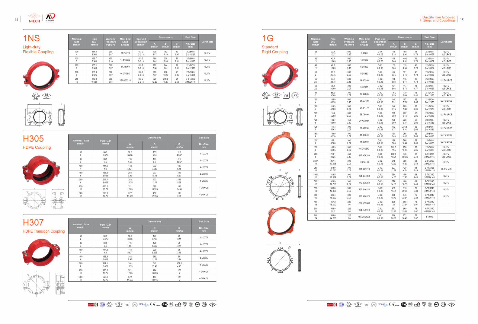
1GStandard Rigid Coupling
VdSFMAPPROVED LOSS
PRE
VENTIO
N CERTIFICATION
BOARD
1NSLight-duty Flexible Coupling
Nominal Size
mm/in
Pipe O.D
mm/in
Working PressurePSI/MPa
Max. End Load
kN/Lbs
Pipe End Separation
mm/in
Dimensions Bolt Size
CertificateA
mm/inB
mm/inC
mm/inNo.-Size
mm
1004
114.34.500
3002.07 21.2/4770 0-3.2
0-0.131395.47
1827.16
501.97
2-3/8X552-M10X57 UL FM
1255
139.75.500
4503.10 47.5/10680 0-3.2
0-0.131686.61
2288.98
512.01
2-5/8X802-M16X85 UL FM
1656
165.16.500
3002.07 44.3/9960 0-3.2
0-0.131927.56
2449.61
512.01
2-1/2X752-M12X76 UL FM
1656
168.36.625
3002.07 46.0/10340 0-3.2
0-0.132007.87
26610.47
522.05
2-5/8X852-M16X85 UL FM
25010
273.010.750
3002.07 121.0/27210 0-3.2
0-0.13320
12.60398.015.67
642.52
2-3/4X1202-M20X115 UL FM
FMAPPROVED
H305HDPE Coupling
H307HDPE Transition Coupling
Nominal Sizemm/in
Pipe O.Dmm/in
Dimensions Bolt Size
Amm/in
Bmm/in
Cmm/in
No.-Sizemm
502
60.32.375
86.53.406
1335.24
1164.567 4-1/2X70
803
88.93.5
1184.65
1656.5
1164.567 4-1/2X75
1004
114.34.5
1485.827
2027.953
1465.75 4-1/2X75
1506
168.36.625
2037.99
27310.75
1495.87 4-5/8X85
2008
219.18.625
26310.35
33313.11
1525.98 4-5/8X85
25010
273.010.75
32112.65
39915.709
1656.496 4-3/4X120
30012
323.912.75
37214.656
45217.795
1857.28 4-3/4X120
Nominal Sizemm/in
Pipe O.Dmm/in
Dimensions Bolt Size
Amm/in
Bmm/in
Cmm/in
No.-Sizemm
502
60.32.375
86.53.406
1475.787
793.11 4-1/2X70
803
88.93.5
1164.567
1766.929
793.11 4-1/2X75
1004
114.34.5
1485.827
2098.228
953.75 4-1/2X75
1506
168.36.625
2027.95
28011.02
953.74 4-5/8X85
2008
219.18.625
26410.39
34213.46
107.54.23 4-5/8X85
25010
273.010.75
32112.65
42416.693
1275 4-3/4X120
30012
323.912.75
37214.656
48319.016
1275 4-3/4X120
Nominal Size
mm/in
Pipe O.D
mm/in
Working PressurePSI/MPa
Max. End Load
kN/Lbs
Pipe End Separation
mm/in
Dimensions Bolt Size
CertificateA
mm/inB
mm/inC
mm/inNo.-Size
mm
251
33.71.327
5003.45 3.0/680 0-1.6
0-0.0659
2.331003.94
441.74
2-3/8X552-M10X57
UL FMVdS LPCB
321¼
42.41.669
5003.45 4.8/1080 0-1.6
0-0.0666
2.60109.54.31
451.78
2-3/8X552-M10X57
UL FMVdS LPCB
401½
48.31.900
5003.45 6.3/1420 0-3.2
0-0.1372
2.841154.53
45 1.78
2-3/8X552-M10X57
UL FMVdS LPCB
502
60.32.375
3002.07 5.9/1330 0-3.2
0-0.1385
3.351315.16
451.78
2-3/8X552-M10X57
UL FMVdS LPCB
652½
73.02.875
5003.45 14.4/3240 0-3.2
0-0.1398
3.861455.71
451.78
2-3/8X552-M10X57 UL FM LPCB
652½
76.13.000
3002.07 9.4/2120 0-3.2
0-0.131013.98
1475.78
451.77
2-3/8X552-M10X57
UL FMVdS LPCB
803
88.93.500
3002.07 12.8/2885 0-3.2
0-0.13115.04.53
1706.69
461.82
2-1/2X702-M12X70
UL FMVdS LPCB
1004
108.04.250
5003.45 31.5/7100 0-3.2
0-0.131405.51
1977.76
522.05
2-1/2X702-M12X70 UL FM LPCB
1004
114.34.500
3002.07 21.2/4770 0-3.2
0-0.131465.75
2007.88
522.05
2-1/2X702-M12X70
UL FMVdS LPCB
1255
1335.250
3002.07 28.7/6460 0-3.2
0-0.131656.50
2329.13
522.05
2-5/8X852-M16X85 UL FM LPCB
1255
139.75.500
4503.10 47.5/10680 0-3.2
0-0.131706.69
2389.37
522.05
2-5/8X852-M16X85
UL FMVdS LPCB
1255
141.35.563
3002.07 32.4/7290 0-3.2
0-0.131726.77
236.59.31
522.05
2-5/8X852-M16X85 UL FM LPCB
1506
159.06.250
3002.07 41.0/9240 0-3.2
0-0.131907.48
25810.16
522.05
2-5/8X852-M16X85 UL FM LPCB
1506
165.16.500
3002.07 44.3/9960 0-3.2
0-0.131987.80
26610.47
522.05
2-5/8X852-M16X85 UL FM LPCB
1506
168.36.625
3002.07 46.0/10340 0-3.2
0-0.13202.07.95
27010.63
522.05
2-5/8X852-M16X85
UL FMVdS LPCB
2008
219.18.625
4503.10 116.9/26280 0-3.2
0-0.13260.010.24
34613.625
622.44
2-3/4X1152-M20X115
UL FMVdS LPCB
250A10
267.410.528
300 2.07 116/26130 0-3.2
0-0.13318
12.52396
15.6063
2.482-3/4X1202-M20X115 UL FM
25010
273.010.750
3002.07 121.0/27210 0-3.2
0-0.13327
12.88420
16.5463
2.482-7/8X125
2-M22X125 UL FM VdS
300A12
318.512.539
3002.07 164.8/37080 0-3.2
0-0.13364
14.33456
17.9563
2.482-7/8X140
2-M22X140 UL FM
30012
323.912.750
3002.07 170.3/38280 0-3.2
0-0.13378
14.88466
18.3563
2.482-7/8X140
2-M22X140 UL FM
35014
355.614.000
3002.07 205.5/46220 0-3.2
0-0.13415
16.34510
20.0872
2.843-7/8X140
3-M22X140 UL FM
40016
406.416.000
3002.07 268.4/60370 0-3.2
0-0.13468
18.43575
22.6472
2.843-7/8X140
3-M22X140 UL FM
45018
457.218.000
2251.6 262.5/59060 0-3.2
0-0.1350820
60823.94
783.07
3-7/8X1403-M22X140 ——
50020
508.020.0
2251.6 324.1/72910 0-3.2
0-0.13563
22.17660
25.9878
3.074-7/8X140
4-M22X140 ——
60024
609.624.000
2251.6 466.7/104990 0-3.2
0-0.13668
26.30772
30.4078
3.07 4-1X140 ——
VdS 1128 T STS2710Y44
WRASA P P R O V E D
P R O D U C TFM
APPROVED LOSS P
REVE
NTION CERTIFICATIO
N BO
ARD
CERTIF ICATIO
N
方
圆认证
BUREAU VERITASVdS 1128 T STS2710Y44
WRASA P P R O V E D
P R O D U C TFM
APPROVED LOSS P
REVE
NTION CERTIFICATIO
N BO
ARD
CERTIF ICATIO
N
方
圆认证
BUREAU VERITAS
Ductile Iron Grooved Fittings and Couplings 1514
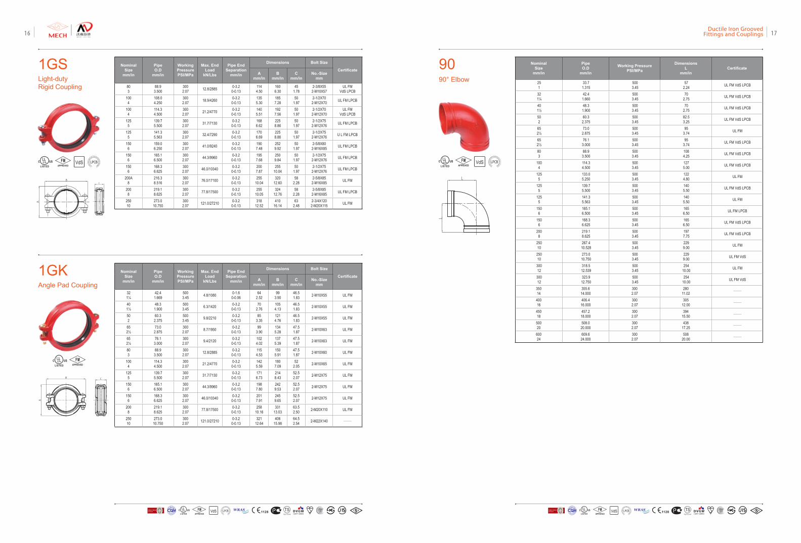
9090° Elbow
Nominal Size
mm/in
Pipe O.D
mm/in
Working PressurePSI/MPa
DimensionsL
mm/inCertificate
251
33.71.315
5003.45
572.24 UL FM VdS LPCB
321¼
42.41.660
5003.45
702.75 UL FM VdS LPCB
401½
48.31.900
5003.45
702.75 UL FM VdS LPCB
502
60.32.375
5003.45
82.53.25 UL FM VdS LPCB
652½
73.02.875
5003.45
953.74 UL FM
652½
76.13.000
5003.45
953.74 UL FM VdS LPCB
803
88.93.500
5003.45
1084.25 UL FM VdS LPCB
1004
114.34.500
5003.45
1275.00 UL FM VdS LPCB
1255
133.05.250
5003.45
1224.80 UL FM
1255
139.75.500
5003.45
1405.50 UL FM VdS LPCB
1255
141.35.563
5003.45
1405.50 UL FM
1506
165.16.500
5003.45
1656.50 UL FM LPCB
1506
168.36.625
5003.45
1656.50 UL FM VdS LPCB
2008
219.18.625
5003.45
1977.75 UL FM VdS LPCB
25010
267.410.528
5003.45
2299.00 UL FM
25010
273.010.750
5003.45
2299.00 UL FM VdS
30012
318.512.539
5003.45
25410.00 UL FM
30012
323.912.750
5003.45
25410.00 UL FM VdS
35014
355.614.000
3002.07
28011.02 ——
40016
406.416.000
3002.07
30512.00 ——
45018
457.218.000
3002.07
39415.50 ——
50020
508.020.000
3002.07
43817.25 ——
60024
609.624.000
3002.07
50820.00 ——
VdSFMAPPROVED LOSS
PRE
VENTIO
N CERTIFICATION
BOARD
1GSLight-duty Rigid Coupling
1GKAngle Pad Coupling
Nominal Size
mm/in
Pipe O.D
mm/in
Working PressurePSI/MPa
Max. End Load
kN/Lbs
Pipe End Separation
mm/in
Dimensions Bolt Size
CertificateA
mm/inB
mm/inC
mm/inNo.-Size
mm
803
88.93.500
3002.07 12.8/2885 0-3.2
0-0.131144.50
1606.30
451.78
2-3/8X552-M10X57
UL FMVdS LPCB
1004
108.04.250
3002.07 18.9/4260 0-3.2
0-0.131355.30
1857.28
501.97
2-1/2X702-M12X70 UL FM LPCB
1004
114.34.500
3002.07 21.2/4770 0-3.2
0-0.131405.51
1927.56
501.97
2-1/2X702-M12X70
UL FMVdS LPCB
1255
139.75.500
3002.07 31.7/7130 0-3.2
0-0.131686.62
2258.86
501.97
2-1/2X752-M12X76 UL FM LPCB
1255
141.35.563
3002.07 32.4/7290 0-3.2
0-0.131706.69
2258.86
501.97
2-1/2X752-M12X76 U L FM LPCB
1506
159.06.250
3002.07 41.0/9240 0-3.2
0-0.131907.48
2529.92
501.97
2-5/8X802-M16X85 UL FM LPCB
1506
165.16.500
3002.07 44.3/9960 0-3.2
0-0.131957.68
2509.84
501.97
2-1/2X752-M12X76 UL FM LPCB
1506
168.36.625
3002.07 46.0/10340 0-3.2
0-0.132007.87
25510.04
501.97
2-1/2X752-M12X76 UL FM LPCB
200A8
216.38.516
3002.07 76.0/17100 0-3.2
0-0.13255
10.04320
12.6058
2.282-5/8X85
2-M16X85 UL FM
2008
219.18.625
3002.07 77.8/17500 0-3.2
0-0.13255
10.05324
12.7658
2.282-5/8X85
2-M16X85 UL FM LPCB
25010
273.010.750
3002.07 121.0/27210 0-3.2
0-0.13318
12.52410
16.1463
2.482-3/4X1202-M20X115 UL FM
Nominal Size
mm/in
Pipe O.D
mm/in
Working PressurePSI/MPa
Max. End Load
kN/Lbs
Pipe End Separation
mm/in
Dimensions Bolt Size
CertificateA
mm/inB
mm/inC
mm/inNo.-Size
mm
321¼
42.41.669
5003.45 4.8/1080 0-1.6
0-0.0664
2.5299
3.9046.51.83 2-M10X55 UL FM
401½
48.31.900
5003.45 6.3/1420 0-3.2
0-0.1370
2.761054.13
46.51.83 2-M10X55 UL FM
502
60.32.375
5003.45 9.8/2210 0-3.2
0-0.1385
3.351214.76
46.51.83 2-M10X55 UL FM
652½
73.02.875
3002.07 8.7/1950 0-3.2
0-0.1399
3.901345.28
47.51.87 2-M10X63 UL FM
652½
76.13.000
3002.07 9.4/2120 0-3.2
0-0.131024.02
1375.39
47.51.87 2-M10X63 UL FM
803
88.93.500
3002.07 12.8/2885 0-3.2
0-0.131154.53
1505.91
47.51.87 2-M10X60 UL FM
1004
114.34.500
3002.07 21.2/4770 0-3.2
0-0.131425.59
1807.09
522.05 2-M10X65 UL FM
1255
139.75.500
3002.07 31.7/7130 0-3.2
0-0.131716.73
2148.43
52.52.07 2-M12X75 UL FM
1506
165.16.500
3002.07 44.3/9960 0-3.2
0-0.131987.80
2429.53
52.52.07 2-M12X75 UL FM
1506
168.36.625
3002.07 46.0/10340 0-3.2
0-0.132017.91
2459.65
52.52.07 2-M12X75 UL FM
2008
219.18.625
3002.07 77.8/17500 0-3.2
0-0.13258
10.16331
13.0363.52.50 2-M20X110 UL FM
25010
273.010.750
3002.07 121.0/27210 0-3.2
0-0.13321
12.64406
15.9864.52.54 2-M22X140 ——
VdSFMAPPROVED LOSS
PRE
VENTIO
N CERTIFICATION
BOARD
FMAPPROVED
VdS 1128 T STS2710Y44
WRASA P P R O V E D
P R O D U C TFM
APPROVED LOSS P
REVE
NTION CERTIFICATIO
N BO
ARD
CERTIF ICATIO
N
方
圆认证
BUREAU VERITASVdS 1128 T STS2710Y44
WRASA P P R O V E D
P R O D U C TFM
APPROVED LOSS P
REVE
NTION CERTIFICATIO
N BO
ARD
CERTIF ICATIO
N
方
圆认证
BUREAU VERITAS
Ductile Iron Grooved Fittings and Couplings 1716
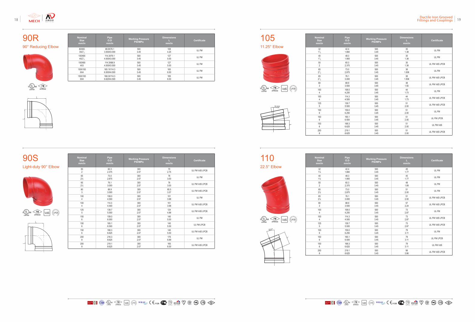
11022.5° Elbow
Nominal Size
mm/in
Pipe O.D
mm/in
Working PressurePSI/MPa
DimensionsL
mm/inCertificate
321¼
42.41.660
5003.45
451.77 UL FM
401½
48.31.900
5003.45
451.77 UL FM
502
60.32.375
5003.45
481.89 UL FM
652½
73.02.875
5003.45
512.00 UL FM
652½
76.13.000
5003.45
512.00 UL FM VdS LPCB
803
88.93.500
5003.45
572.24 UL FM VdS LPCB
1004
108.04.250
5003.45
732.87 UL FM
1004
114.34.500
5003.45
732.87 UL FM VdS LPCB
1255
139.75.500
5003.45
732.87 UL FM VdS LPCB
1506
159.06.250
5003.45
793.11 UL FM
1506
165.16.500
5003.45
793.11 UL FM LPCB
1506
168.36.625
5003.45
793.11 UL FM VdS
2008
219.18.625
5003.45
983.86 UL FM VdS LPCB
VdSFMAPPROVED LOSS
PRE
VENTIO
N CERTIFICATION
BOARD
10511.25° Elbow
Nominal Size
mm/in
Pipe O.D
mm/in
Working PressurePSI/MPa
DimensionsL
mm/inCertificate
3211/4
42.41.660
5003.45
351.38 UL FM
4011/2
48.31.900
5003.45
351.38 UL FM
502
60.32.375
5003.45
351.38 UL FM VdS LPCB
6521/2
73.02.875
5003.45
381.506 UL FM
6521/2
76.13.000
5003.45
381.506 UL FM VdS LPCB
803
88.93.500
5003.45
381.50 UL FM VdS LPCB
1004
108.04.250
5003.45
441.73 UL FM
1004
114.34.500
5003.45
441.73 UL FM VdS LPCB
1255
139.75.500
5003.45
512.00 UL FM VdS LPCB
1506
159.06.250
5003.45
512.00 UL FM
1506
165.16.500
5003.45
512.00 UL FM LPCB
1506
168.36.625
5003.45
512.00 UL FM VdS
2008
219.18.625
5003.45
512.00 UL FM VdS LPCB
VdSFMAPPROVED LOSS
PRE
VENTIO
N CERTIFICATION
BOARD
90R90° Reducing Elbow
90SLight-duty 90° Elbow
Nominal Size
mm/in
Pipe O.D
mm/in
Working PressurePSI/MPa
DimensionsL
mm/inCertificate
80X653X21/2
88.9X76.13.500X3.000
5003.45
1084.25 UL FM
100X654X21/2
114.3X76.14.500X3.000
5003.45
1275.00 UL FM
100X804X3
114.3X88.94.500X3.500
5003.45
1275.00 UL FM
150X1006X4
165.1X114.36.500X4.500
5003.45
1656.50 UL FM
150X1006X4
168.3X114.36.625X4.500
5003.45
1656.50 UL FM
Nominal Size
mm/in
Pipe O.D
mm/in
Working PressurePSI/MPa
DimensionsL
mm/inCertificate
502
60.32.375
3002.07
702.75 UL FM VdS LPCB
652½
73.02.875
3002.07
763.00 UL FM
652½
76.13.000
3002.07
763.00 UL FM VdS LPCB
803
88.93.500
3002.07
85.53.37 UL FM VdS LPCB
1004
108.04.500
3002.07
1013.98 UL FM
1004
114.34.500
3002.07
1013.98 UL FM VdS LPCB
1255
139.75.500
3002.07
1244.88 UL FM VdS LPCB
1506
159.06.500
3002.07
1405.50 UL FM
1506
165.16.500
3002.07
1405.50 UL FM LPCB
1506
168.36.625
3002.07
1405.50 UL FM VdS LPCB
2008
216.38.625
3002.07
1756.89 UL FM
2008
219.18.625
3002.07
1656.50 UL FM VdS LPCB
VdSFMAPPROVED LOSS
PRE
VENTIO
N CERTIFICATION
BOARD
FMAPPROVED
VdS 1128 T STS2710Y44
WRASA P P R O V E D
P R O D U C TFM
APPROVED LOSS P
REVE
NTION CERTIFICATIO
N BO
ARD
CERTIF ICATIO
N
方
圆认证
BUREAU VERITASVdS 1128 T STS2710Y44
WRASA P P R O V E D
P R O D U C TFM
APPROVED LOSS P
REVE
NTION CERTIFICATIO
N BO
ARD
CERTIF ICATIO
N
方
圆认证
BUREAU VERITAS
Ductile Iron Grooved Fittings and Couplings 1918
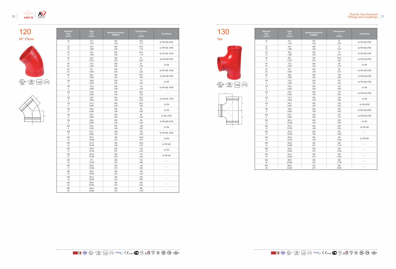
130Tee
Nominal Size
mm/in
Pipe O.D
mm/in
Working PressurePSI/MPa
DimensionsL
mm/inCertificate
251
33.71.315
5003.45
572.24 UL FM VdS LPCB
321¼
42.41.660
5003.45
702.75 UL FM VdS LPCB
401½
48.31.900
5003.45
702.75 UL FM VdS LPCB
502
60.32.375
5003.45
82.53.25 UL FM VdS LPCB
652½
73.02.875
5003.45
953.74 UL FM
652½
76.13.000
5003.45
953.74 UL FM VdS LPCB
803
88.93.500
5003.45
1084.25 UL FM VdS LPCB
1004
114.34.500
5003.45
1275.00 UL FM VdS LPCB
1255
133.05.250
5003.45
1224.80 UL FM
1255
139.75.500
5003.45
1405.50 UL FM VdS LPCB
1255
141.35.563
5003.45
1405.50 UL FM
1506
165.16.500
5003.45
1656.50 UL FM LPCB
1506
168.36.625
5003.45
1656.50 UL FM VdS LPCB
2008
219.18.625
5003.45
1977.75 UL FM VdS LPCB
25010
267.410.528
5003.45
2299.00 UL FM
25010
273.010.750
5003.45
2299.00 UL FM VdS
30012
318.512.539
5003.45
25410.00 ——
30012
323.912.750
5003.45
25410.00 UL FM VdS
35014
355.614.000
3002.07
28011.02 ——
40016
406.416.000
3002.07
30512.00 ——
45018
457.218.000
3002.07
39415.50 ——
50020
508.020.000
3002.07
43817.25 ——
60024
609.624.000
3002.07
50820.00 ——
VdSFMAPPROVED LOSS
PRE
VENTIO
N CERTIFICATION
BOARD
12045° Elbow
Nominal Size
mm/in
Pipe O.D
mm/in
Working PressurePSI/MPa
DimensionsL
mm/inCertificate
251
33.71.315
5003.45
44.51.75 UL FM VdS LPCB
321¼
42.41.660
5003.45
44.51.75 UL FM VdS LPCB
401½
48.31.900
5003.45
44.51.75 UL FM VdS LPCB
502
60.32.375
5003.45
512.00 UL FM VdS LPCB
652½
73.02.875
5003.45
572.24 UL FM
652½
76.13.000
5003.45
572.24 UL FM VdS LPCB
803
88.93.500
5003.45
63.52.50 UL FM VdS LPCB
1004
108.04.250
5003.45
763.00 UL FM
1004
114.34.500
5003.45
763.00 UL FM VdS LPCB
1255
133.05.250
5003.45
82.53.25 ——
1255
139.75.500
5003.45
82.53.25 UL FM VdS LPCB
1255
141.35.563
5003.45
82.53.25 UL FM
1506
159.06.250
5003.45
893.50 UL FM
1506
165.16.500
5003.45
893.50 UL FM LPCB
1506
168.36.625
5003.45
893.50 UL FM VdS LPCB
2008
216.38.516
5003.45
1084.25 UL FM
2008
219.18.625
5003.45
1084.25 UL FM VdS LPCB
25010
267.410.528
3002.07
120.54.75 UL FM
25010
273.010.750
5003.45
120.54.75 UL FM VdS
30012
318.512.750
3002.07
1335.25 UL FM
30012
323.912.750
5003.45
1335.25 UL FM VdS
30012
37712.750
3002.07
1224.80 ——
35014
355.614.000
3002.07
1526.00 ——
40016
406.416.000
3002.07
1847.25 ——
45018
457.218.000
3002.07
2038.00 ——
50020
508.020.000
3002.07
2299.00 ——
60024
609.624.000
3002.07
28011.00 ——
VdSFMAPPROVED LOSS
PRE
VENTIO
N CERTIFICATION
BOARD
VdS 1128 T STS2710Y44
WRASA P P R O V E D
P R O D U C TFM
APPROVED LOSS P
REVE
NTION CERTIFICATIO
N BO
ARD
CERTIF ICATIO
N
方
圆认证
BUREAU VERITASVdS 1128 T STS2710Y44
WRASA P P R O V E D
P R O D U C TFM
APPROVED LOSS P
REVE
NTION CERTIFICATIO
N BO
ARD
CERTIF ICATIO
N
方
圆认证
BUREAU VERITAS
Ductile Iron Grooved Fittings and Couplings 2120
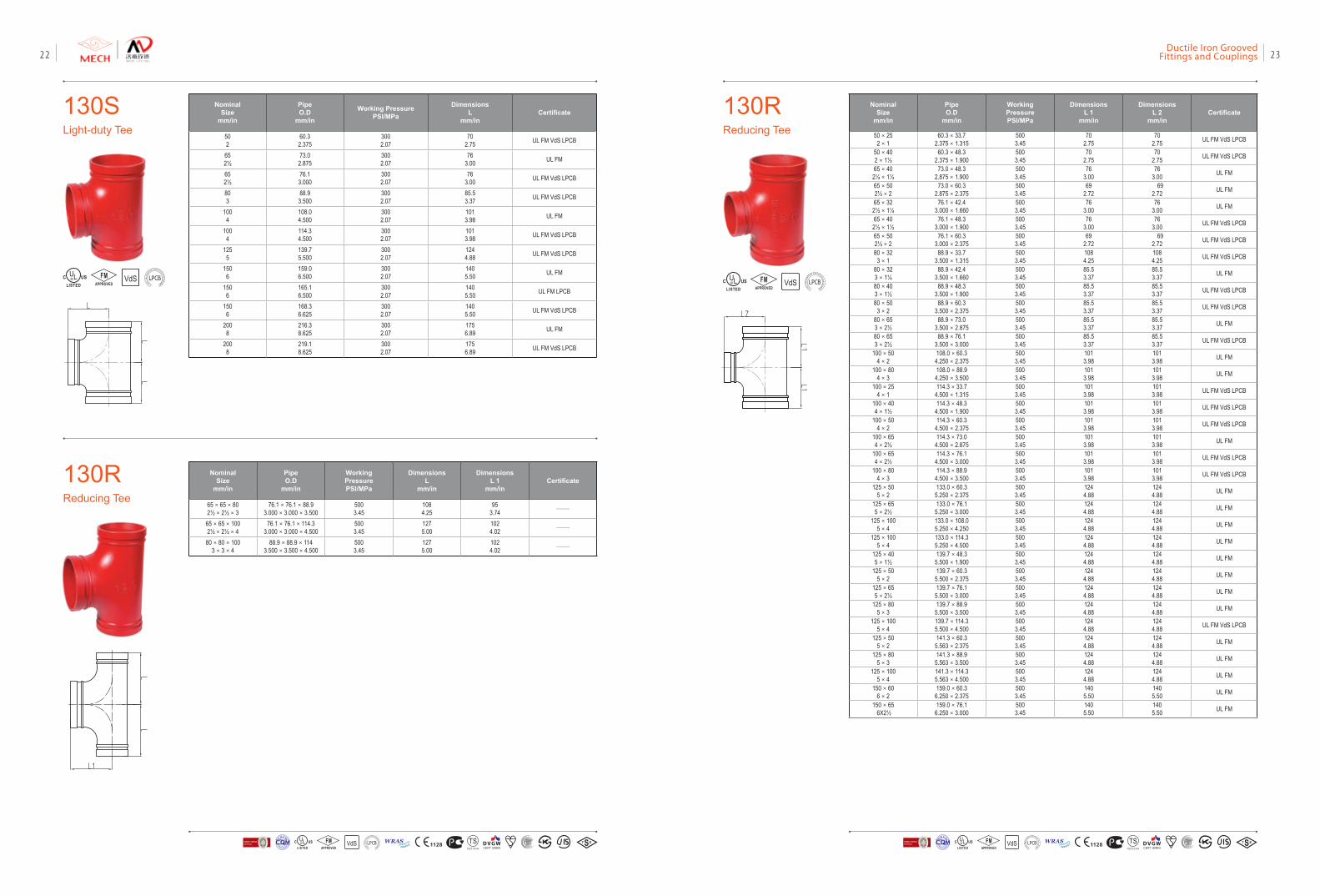
130RReducing Tee
Nominal Size
mm/in
Pipe O.D
mm/in
Working PressurePSI/MPa
DimensionsL 1
mm/in
DimensionsL 2
mm/inCertificate
50×252×1
60.3×33.72.375×1.315
5003.45
702.75
702.75 UL FM VdS LPCB
50×402×1½
60.3×48.32.375×1.900
5003.45
702.75
702.75 UL FM VdS LPCB
65×402½×1½
73.0×48.32.875×1.900
5003.45
763.00
763.00 UL FM
65×502½×2
73.0×60.32.875×2.375
5003.45
692.72
692.72 UL FM
65×322½×1¼
76.1×42.43.000×1.660
5003.45
763.00
763.00 UL FM
65×402½×1½
76.1×48.33.000×1.900
5003.45
763.00
763.00 UL FM VdS LPCB
65×502½×2
76.1×60.33.000×2.375
5003.45
692.72
692.72 UL FM VdS LPCB
80×323×1
88.9×33.73.500×1.315
5003.45
1084.25
1084.25 UL FM VdS LPCB
80×323×1¼
88.9×42.43.500×1.660
5003.45
85.53.37
85.53.37 UL FM
80×403×1½
88.9×48.33.500×1.900
5003.45
85.53.37
85.53.37 UL FM VdS LPCB
80×503×2
88.9×60.33.500×2.375
5003.45
85.53.37
85.53.37 UL FM VdS LPCB
80×653×2½
88.9×73.03.500×2.875
5003.45
85.53.37
85.53.37 UL FM
80×653×2½
88.9×76.13.500×3.000
5003.45
85.53.37
85.53.37 UL FM VdS LPCB
100×504×2
108.0×60.34.250×2.375
5003.45
1013.98
1013.98 UL FM
100×804×3
108.0×88.94.250×3.500
5003.45
1013.98
1013.98 UL FM
100×254×1
114.3×33.74.500×1.315
5003.45
1013.98
1013.98 UL FM VdS LPCB
100×404×1½
114.3×48.34.500×1.900
5003.45
1013.98
1013.98 UL FM VdS LPCB
100×504×2
114.3×60.34.500×2.375
5003.45
1013.98
1013.98 UL FM VdS LPCB
100×654×2½
114.3×73.04.500×2.875
5003.45
1013.98
1013.98 UL FM
100×654×2½
114.3×76.14.500×3.000
5003.45
1013.98
1013.98 UL FM VdS LPCB
100×804×3
114.3×88.94.500×3.500
5003.45
1013.98
1013.98 UL FM VdS LPCB
125×505×2
133.0×60.35.250×2.375
5003.45
1244.88
1244.88 UL FM
125×655×2½
133.0×76.15.250×3.000
5003.45
1244.88
1244.88 UL FM
125×1005×4
133.0×108.05.250×4.250
5003.45
1244.88
1244.88 UL FM
125×1005×4
133.0×114.35.250×4.500
5003.45
1244.88
1244.88 UL FM
125×405×1½
139.7×48.35.500×1.900
5003.45
1244.88
1244.88 UL FM
125×505×2
139.7×60.35.500×2.375
5003.45
1244.88
1244.88 UL FM
125×655×2½
139.7×76.15.500×3.000
5003.45
1244.88
1244.88 UL FM
125×805×3
139.7×88.95.500×3.500
5003.45
1244.88
1244.88 UL FM
125×1005×4
139.7×114.35.500×4.500
5003.45
1244.88
1244.88 UL FM VdS LPCB
125×505×2
141.3×60.35.563×2.375
5003.45
1244.88
1244.88 UL FM
125×805×3
141.3×88.95.563×3.500
5003.45
1244.88
1244.88 UL FM
125×1005×4
141.3×114.35.563×4.500
5003.45
1244.88
1244.88 UL FM
150×606×2
159.0×60.36.250×2.375
5003.45
1405.50
1405.50 UL FM
150×65 6X2½
159.0×76.16.250×3.000
5003.45
1405.50
1405.50 UL FM
VdSFMAPPROVED LOSS
PRE
VENTIO
N CERTIFICATION
BOARD
130SLight-duty Tee
Nominal Size
mm/in
Pipe O.D
mm/in
Working PressurePSI/MPa
DimensionsL
mm/inCertificate
502
60.32.375
3002.07
702.75 UL FM VdS LPCB
652½
73.02.875
3002.07
763.00 UL FM
652½
76.13.000
3002.07
763.00 UL FM VdS LPCB
803
88.93.500
3002.07
85.53.37 UL FM VdS LPCB
1004
108.04.500
3002.07
1013.98 UL FM
1004
114.34.500
3002.07
1013.98 UL FM VdS LPCB
1255
139.75.500
3002.07
1244.88 UL FM VdS LPCB
1506
159.06.500
3002.07
1405.50 UL FM
1506
165.16.500
3002.07
1405.50 UL FM LPCB
1506
168.36.625
3002.07
1405.50 UL FM VdS LPCB
2008
216.38.625
3002.07
1756.89 UL FM
2008
219.18.625
3002.07
1756.89 UL FM VdS LPCB
VdSFMAPPROVED LOSS
PRE
VENTIO
N CERTIFICATION
BOARD
130RReducing Tee
Nominal Size
mm/in
Pipe O.D
mm/in
Working PressurePSI/MPa
DimensionsL
mm/in
DimensionsL 1
mm/inCertificate
65×65×802½×2½×3
76.1×76.1×88.93.000×3.000×3.500
5003.45
1084.25
953.74 ——
65×65×1002½×2½×4
76.1×76.1×114.33.000×3.000×4.500
5003.45
1275.00
1024.02 ——
80×80×1003×3×4
88.9×88.9×1143.500×3.500×4.500
5003.45
1275.00
1024.02 ——
VdS 1128 T STS2710Y44
WRASA P P R O V E D
P R O D U C TFM
APPROVED LOSS P
REVE
NTION CERTIFICATIO
N BO
ARD
CERTIF ICATIO
N
方
圆认证
BUREAU VERITASVdS 1128 T STS2710Y44
WRASA P P R O V E D
P R O D U C TFM
APPROVED LOSS P
REVE
NTION CERTIFICATIO
N BO
ARD
CERTIF ICATIO
N
方
圆认证
BUREAU VERITAS
Ductile Iron Grooved Fittings and Couplings 2322
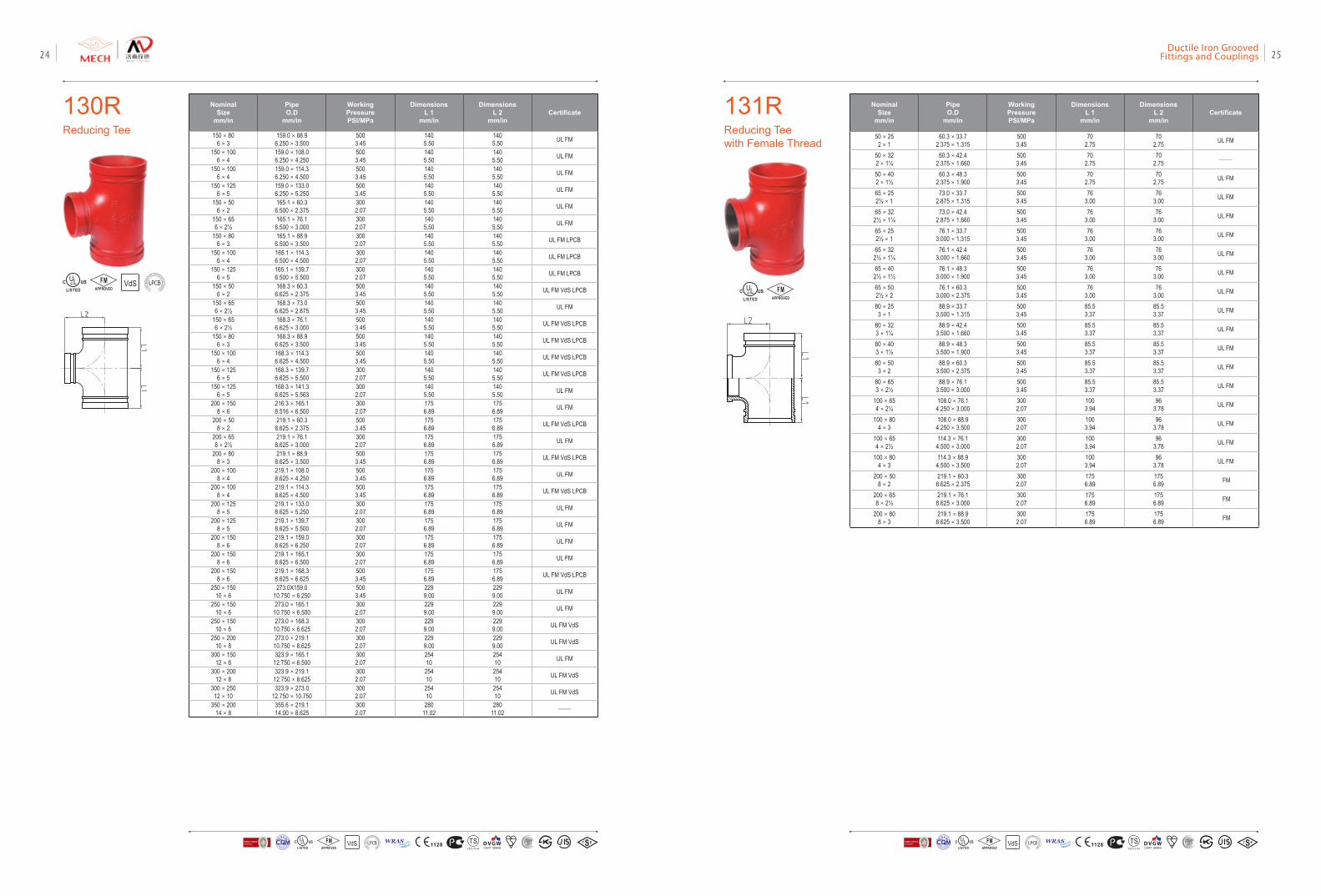
131RReducing Tee with Female Thread
Nominal Size
mm/in
Pipe O.D
mm/in
Working PressurePSI/MPa
DimensionsL 1
mm/in
DimensionsL 2
mm/inCertificate
50×252×1
60.3×33.72.375×1.315
5003.45
702.75
702.75 UL FM
50×322×1¼
60.3×42.42.375×1.660
5003.45
702.75
702.75 ——
50×402×1½
60.3×48.32.375×1.900
5003.45
702.75
702.75 UL FM
65×252½×1
73.0×33.72.875×1.315
5003.45
763.00
763.00 UL FM
65×322½×1¼
73.0×42.42.875×1.660
5003.45
763.00
763.00 UL FM
65×252½×1
76.1×33.73.000×1.315
5003.45
763.00
763.00 UL FM
65×322½×1¼
76.1×42.43.000×1.660
5003.45
763.00
763.00 UL FM
65×402½×1½
76.1×48.33.000×1.900
5003.45
763.00
763.00 UL FM
65×502½×2
76.1×60.33.000×2.375
5003.45
763.00
763.00 UL FM
80×253×1
88.9×33.73.500×1.315
5003.45
85.53.37
85.53.37 UL FM
80×323×1¼
88.9×42.43.500×1.660
5003.45
85.53.37
85.53.37 UL FM
80×403×1½
88.9×48.33.500×1.900
5003.45
85.53.37
85.53.37 UL FM
80×503×2
88.9×60.33.500×2.375
5003.45
85.53.37
85.53.37 UL FM
80×653×2½
88.9×76.13.500×3.000
5003.45
85.53.37
85.53.37 UL FM
100×654×2½
108.0×76.14.250×3.000
3002.07
1003.94
963.78 UL FM
100×804×3
108.0×88.94.250×3.500
3002.07
1003.94
963.78 UL FM
100×654×2½
114.3×76.14.500×3.000
3002.07
1003.94
963.78 UL FM
100×804×3
114.3×88.94.500×3.500
3002.07
1003.94
963.78 UL FM
200×508×2
219.1×60.38.625×2.375
3002.07
1756.89
1756.89 FM
200×658×2½
219.1×76.18.625×3.000
3002.07
1756.89
1756.89 FM
200×808×3
219.1×88.98.625×3.500
3002.07
1756.89
1756.89 FM
FMAPPROVED
Nominal Size
mm/in
Pipe O.D
mm/in
Working PressurePSI/MPa
DimensionsL 1
mm/in
DimensionsL 2
mm/inCertificate
150×806×3
159.0×88.96.250×3.500
5003.45
1405.50
1405.50 UL FM
150×1006×4
159.0×108.06.250×4.250
5003.45
1405.50
1405.50 UL FM
150×1006×4
159.0×114.36.250×4.500
5003.45
1405.50
1405.50 UL FM
150×1256×5
159.0×133.06.250×5.250
5003.45
1405.50
1405.50 UL FM
150×506×2
165.1×60.36.500×2.375
3002.07
1405.50
1405.50 UL FM
150×656×2½
165.1×76.16.500×3.000
3002.07
1405.50
1405.50 UL FM
150×806×3
165.1×88.96.500×3.500
3002.07
1405.50
1405.50 UL FM LPCB
150×1006×4
165.1×114.36.500×4.500
3002.07
1405.50
1405.50 UL FM LPCB
150×1256×5
165.1×139.76.500×5.500
3002.07
1405.50
1405.50 UL FM LPCB
150×506×2
168.3×60.36.625×2.375
5003.45
1405.50
1405.50 UL FM VdS LPCB
150×656×2½
168.3×73.06.625×2.875
5003.45
1405.50
1405.50 UL FM
150×656×2½
168.3×76.16.625×3.000
5003.45
1405.50
1405.50 UL FM VdS LPCB
150×806×3
168.3×88.96.625×3.500
5003.45
1405.50
1405.50 UL FM VdS LPCB
150×1006×4
168.3×114.36.625×4.500
5003.45
1405.50
1405.50 UL FM VdS LPCB
150×1256×5
168.3×139.76.625×5.500
3002.07
1405.50
1405.50 UL FM VdS LPCB
150×1256×5
168.3×141.36.625×5.563
3002.07
1405.50
1405.50 UL FM
200×1508×6
216.3×165.18.516×6.500
3002.07
1756.89
1756.89 UL FM
200×508×2
219.1×60.38.625×2.375
5003.45
1756.89
1756.89 UL FM VdS LPCB
200×658×2½
219.1×76.18.625×3.000
3002.07
1756.89
1756.89 UL FM
200×808×3
219.1×88.98.625×3.500
5003.45
1756.89
1756.89 UL FM VdS LPCB
200×1008×4
219.1×108.08.625×4.250
5003.45
1756.89
1756.89 UL FM
200×1008×4
219.1×114.38.625×4.500
5003.45
1756.89
1756.89 UL FM VdS LPCB
200×1258×5
219.1×133.08.625×5.250
3002.07
1756.89
1756.89 UL FM
200×1258×5
219.1×139.78.625×5.500
3002.07
1756.89
1756.89 UL FM
200×1508×6
219.1×159.08.625×6.250
3002.07
1756.89
1756.89 UL FM
200×1508×6
219.1×165.18.625×6.500
3002.07
1756.89
1756.89 UL FM
200×1508×6
219.1×168.38.625×6.625
5003.45
1756.89
1756.89 UL FM VdS LPCB
250×15010×6
273.0X159.010.750×6.250
5003.45
2299.00
2299.00 UL FM
250×15010×6
273.0×165.110.750×6.500
3002.07
2299.00
2299.00 UL FM
250×15010×6
273.0×168.310.750×6.625
3002.07
2299.00
2299.00 UL FM VdS
250×20010×8
273.0×219.110.750×8.625
3002.07
2299.00
2299.00 UL FM VdS
300×15012×6
323.9×165.112.750×6.500
3002.07
25410
25410 UL FM
300×20012×8
323.9×219.112.750×8.625
3002.07
25410
25410 UL FM VdS
300×25012×10
323.9×273.012.750×10.750
3002.07
25410
25410 UL FM VdS
350×20014×8
355.6×219.114.00×8.625
3002.07
28011.02
28011.02 ——
130RReducing Tee
VdSFMAPPROVED LOSS
PRE
VENTIO
N CERTIFICATION
BOARD
VdS 1128 T STS2710Y44
WRASA P P R O V E D
P R O D U C TFM
APPROVED LOSS P
REVE
NTION CERTIFICATIO
N BO
ARD
CERTIF ICATIO
N
方
圆认证
BUREAU VERITASVdS 1128 T STS2710Y44
WRASA P P R O V E D
P R O D U C TFM
APPROVED LOSS P
REVE
NTION CERTIFICATIO
N BO
ARD
CERTIF ICATIO
N
方
圆认证
BUREAU VERITAS
Ductile Iron Grooved Fittings and Couplings 2524
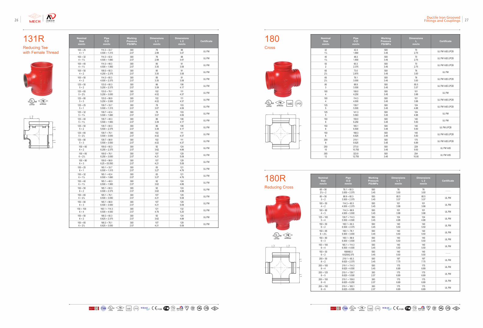
180Cross
180RReducing Cross
Nominal Size
mm/in
Pipe O.D
mm/in
Working PressurePSI/MPa
DimensionsL
mm/inCertificate
321¼
42.41.660
5003.45
702.75 UL FM VdS LPCB
401½
48.31.900
5003.45
702.75 UL FM VdS LPCB
502
60.32.375
5003.45
702.75 UL FM VdS LPCB
652½
73.02.875
5003.45
763.00 UL FM
652½
76.13.000
5003.45
763.00 UL FM VdS LPCB
803
88.93.500
5003.45
85.53.37 UL FM VdS LPCB
1004
108.04.250
5003.45
1013.98 UL FM
1004
114.34.500
5003.45
1013.98 UL FM VdS LPCB
1255
139.75.500
5003.45
1244.88 UL FM VdS LPCB
1255
141.35.563
5003.45
1244.88 UL FM
1506
159.06.250
5003.45
1405.50 UL FM
1506
165.16.500
5003.45
1405.50 UL FM LPCB
1506
168.36.625
5003.45
1405.50 UL FM VdS LPCB
2008
219.18.625
5003.45
1756.89 UL FM VdS LPCB
25010
273.010.750
5003.45
2299.00 UL FM VdS
30012
323.912.750
5003.45
25410.00 UL FM VdS
Nominal Size
mm/in
Pipe O.D
mm/in
Working PressurePSI/MPa
DimensionsL 1
mm/in
DimensionsL 2
mm/inCertificate
65×502½×2
76.1×60.33.000×2.375
5003.45
763.00
763.00 ——
80×503×2
88.9×60.33.500×2.375
5003.45
85.53.37
85.53.37 UL FM
100×504×2
114.3×60.34.500×2.375
5003.45
1013.98
1013.98 UL FM
100×804×3
114.3×88.94.500×3.500
5003.45
1013.98
1013.98 UL FM
125×1005×4
139.7×114.35.500×4.500
5003.45
1244.88
1244.88 UL FM
150×506×2
165.1×60.36.500×2.375
5003.45
1405.50
1405.50 UL FM
150×656×2½
165.1×76.16.500×3.000
5003.45
1405.50
1405.50 UL FM
150×806×3
165.1×88.96.500×3.500
5003.45
1405.50
1405.50 UL FM
150×1006×4
165.1×114.36.500×4.500
5003.45
1405.50
1405.50 UL FM
150×506×2
168X60.36.625X2.375
5003.45
1405.50
1405.50 ——
200×508×2
219.1×60.38.625×2.375
5003.45
1977.75
1977.75 UL FM
200×1008×4
219.1×114.38.625×4.500
5003.45
1756.89
1756.89 UL FM
200×1258×5
219.1×139.78.625×5.500
3002.07
1756.89
1756.89 UL FM
200×1508×6
219.1×159.08.625×6.250
3002.07
1756.89
1756.89 UL FM
200×1508×6
219.1×165.18.625×6.500
3002.07
1756.89
1756.89 UL FM
VdSFMAPPROVED LOSS
PRE
VENTIO
N CERTIFICATION
BOARD
FMAPPROVED
131RReducing Teewith Female Thread
Nominal Size
mm/in
Pipe O.D
mm/in
Working PressurePSI/MPa
DimensionsL 1
mm/in
DimensionsL 2
mm/inCertificate
100×254×1
114.3×33.74.500×1.315
3002.07
762.99
883.47 UL FM
100×324×1¼
114.3×42.44.500×1.660
3002.07
762.99
883.47 UL FM
100×404×1½
114.3×48.34.500×1.900
3002.07
853.35
913.58 UL FM
100×504×2
108.0×60.34.250×2.375
3002.07
853.35
913.58 UL FM
100×504×2
114.3×60.34.500×2.375
3002.07
853.35
913.58 UL FM
125×505×2
133.0×60.35.250×2.375
3002.07
863.39
1064.17 UL FM
125×655×2½
133.0×76.15.250×3.000
3002.07
1024.02
1114.37 UL FM
125×805×3
133.0×88.95.250×3.500
3002.07
1024.02
1114.37 UL FM
125×255×1
139.7×33.75.500×1.315
3002.07
783.07
1034.06 UL FM
125×325×1¼
139.7×42.45.500×1.660
3002.07
783.07
1034.06 UL FM
125×405×1½
139.7×48.35.500×1.900
3002.07
863.39
1064.17 UL FM
125×505×2
139.7×60.35.500×2.375
3002.07
863.39
1064.17 UL FM
125×655×2½
139.7×76.15.500×3.000
3002.07
1024.02
1114.37 UL FM
125×805×3
139.7×88.95.500×3.500
3002.07
1024.02
1114.37 UL FM
150×606×2
159.0×60.36.250×2.375
3002.07
923.62
1244.88 UL FM
150×65 6×2½
159.0×76.16.250×3.000
3002.07
1074.21
1295.08 UL FM
150×806×3
159.0×88.96.25×03.500
3002.07
1074.21
1295.08 UL FM
150×256×1
165.1×33.76.500×1.315
3002.07
833.27
1214.76 UL FM
150×326×1¼
165.1×42.46.500×1.660
3002.07
833.27
1214.76 UL FM
150×406×1½
165.1×48.36.500×1.900
3002.07
923.62
1244.88 UL FM
150×506×2
165.1×60.36.500×2.375
3002.07
923.62
1244.88 UL FM
150×656×2½
165.1×76.16.500×3.000
3002.07
1074.21
1295.08 UL FM
150×806×3
165.1×88.96.500×3.500
3002.07
1074.21
1295.08 UL FM
150×1006×4
165.1×114.36.500×4.500
3002.07
1214.76
1325.20 UL FM
150×506×2
168.3×60.36.625×2.375
3002.07
923.62
1244.88 UL FM
150×656×2½
168.3×76.16.625×3.000
3002.07
1074.21
1295.08 UL FM
FMAPPROVED
VdS 1128 T STS2710Y44
WRASA P P R O V E D
P R O D U C TFM
APPROVED LOSS P
REVE
NTION CERTIFICATIO
N BO
ARD
CERTIF ICATIO
N
方
圆认证
BUREAU VERITASVdS 1128 T STS2710Y44
WRASA P P R O V E D
P R O D U C TFM
APPROVED LOSS P
REVE
NTION CERTIFICATIO
N BO
ARD
CERTIF ICATIO
N
方
圆认证
BUREAU VERITAS
Ductile Iron Grooved Fittings and Couplings 2726
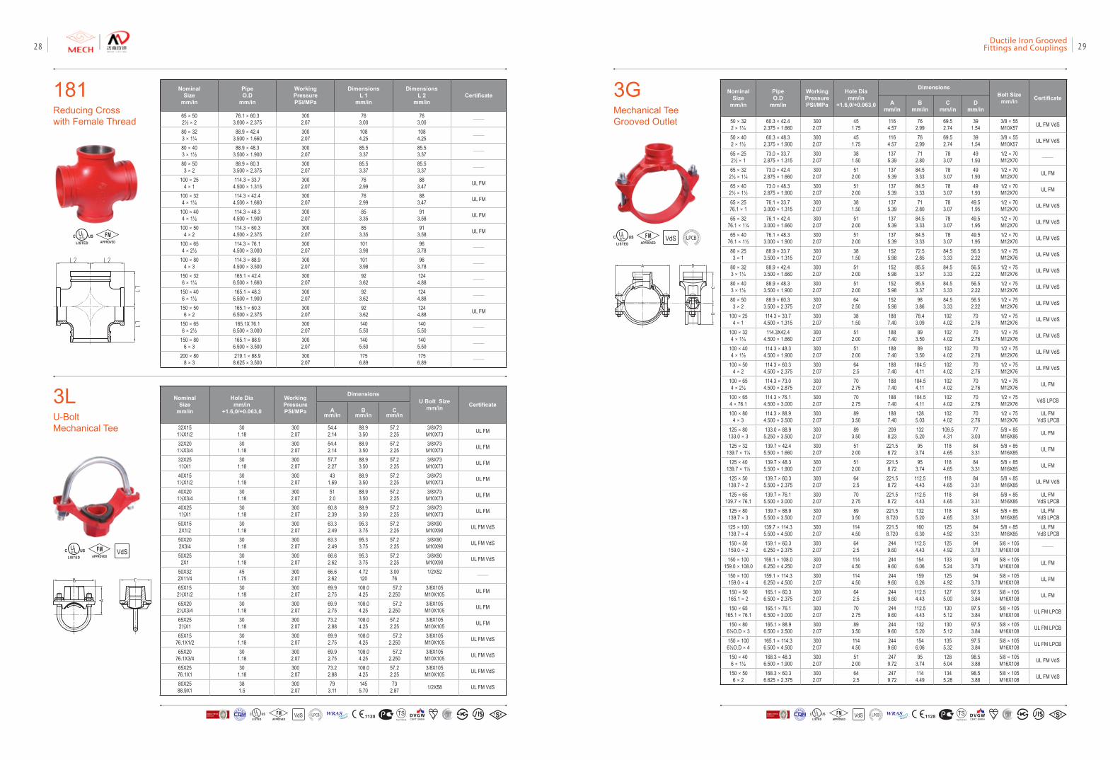
3GMechanical Tee Grooved Outlet
NominalSize
mm/in
PipeO.D
mm/in
Working PressurePSI/MPa
Hole Diamm/in
+1.6,0/+0.063,0
DimensionsBolt Size
mm/in CertificateA
mm/inB
mm/inC
mm/inD
mm/in
50×322×1¼
60.3×42.42.375×1.660
3002.07
451.75
1164.57
762.99
69.52.74
391.54
3/8×55M10X57 UL FM VdS
50×402×1½
60.3×48.32.375×1.900
3002.07
451.75
1164.57
762.99
69.52.74
391.54
3/8×55M10X57 UL FM VdS
65×252½×1
73.0×33.72.875×1.315
3002.07
381.50
1375.39
712.80
783.07
491.93
1/2×70M12X70 ——
65×322½×1¼
73.0×42.42.875×1.660
3002.07
512.00
1375.39
84.53.33
783.07
491.93
1/2×70M12X70 UL FM
65×402½×1½
73.0×48.32.875×1.900
3002.07
512.00
1375.39
84.53.33
783.07
491.93
1/2×70M12X70 UL FM
65×2576.1×1
76.1×33.73.000×1.315
3002.07
381.50
1375.39
712.80
783.07
49.51.95
1/2×70M12X70 UL FM VdS
65×3276.1×1¼
76.1×42.43.000×1.660
3002.07
512.00
1375.39
84.53.33
783.07
49.51.95
1/2×70M12X70 UL FM VdS
65×4076.1×1½
76.1×48.33.000×1.900
3002.07
512.00
1375.39
84.53.33
783.07
49.51.95
1/2×70M12X70 UL FM VdS
80×253×1
88.9×33.73.500×1.315
3002.07
381.50
1525.98
72.52.85
84.53.33
56.52.22
1/2×75M12X76 UL FM VdS
80×323×1¼
88.9×42.43.500×1.660
3002.07
512.00
1525.98
85.53.37
84.53.33
56.52.22
1/2×75M12X76 UL FM VdS
80×403×1½
88.9×48.33.500×1.900
3002.07
512.00
1525.98
85.53.37
84.53.33
56.52.22
1/2×75M12X76 UL FM VdS
80×503×2
88.9×60.33.500×2.375
3002.07
642.50
1525.98
983.86
84.53.33
56.52.22
1/2×75M12X76 UL FM VdS
100×254×1
114.3×33.74.500×1.315
3002.07
381.50
1887.40
78.43.09
1024.02
702.76
1/2×75M12X76 UL FM VdS
100×324×1¼
114.3X42.44.500×1.660
3002.07
512.00
1887.40
893.50
1024.02
702.76
1/2×75M12X76 UL FM VdS
100×404×1½
114.3×48.34.500×1.900
3002.07
512.00
1887.40
893.50
1024.02
702.76
1/2×75M12X76 UL FM VdS
100×504×2
114.3×60.34.500×2.375
3002.07
642.5
1887.40
104.54.11
1024.02
702.76
1/2×75M12X76 UL FM VdS
100×654×2½
114.3×73.04.500×2.875
3002.07
702.75
1887.40
104.54.11
1024.02
702.76
1/2×75M12X76 UL FM
100×654×76.1
114.3×76.14.500×3.000
3002.07
702.75
1887.40
104.54.11
1024.02
702.76
1/2×75M12X76 VdS LPCB
100×804×3
114.3×88.94.500×3.500
3002.07
893.50
1887.40
1285.03
1024.02
702.76
1/2×75M12X76
UL FM VdS LPCB
125×80133.0×3
133.0×88.95.250×3.500
3002.07
893.50
2098.23
1325.20
109.54.31
773.03
5/8×85M16X85 UL FM
125×32139.7×1¼
139.7×42.45.500×1.660
3002.07
512.00
221.58.72
953.74
1184.65
843.31
5/8×85M16X85 UL FM
125×40139.7×1½
139.7×48.35.500×1.900
3002.07
512.00
221.58.72
953.74
1184.65
843.31
5/8×85M16X85 UL FM
125×50139.7×2
139.7×60.35.500×2.375
3002.07
642.5
221.58.72
112.54.43
1184.65
843.31
5/8×85M16X85 UL FM VdS
125×65139.7×76.1
139.7×76.15.500×3.000
3002.07
702.75
221.58.72
112.54.43
1184.65
843.31
5/8×85M16X85
UL FM VdS LPCB
125×80139.7×3
139.7×88.95.500×3.500
3002.07
893.50
221.58.720
1325.20
1184.65
843.31
5/8×85M16X85
UL FM VdS LPCB
125×100139.7×4
139.7×114.35.500×4.500
3002.07
1144.50
221.58.720
1606.30
1254.92
843.31
5/8×85M16X85
UL FM VdS LPCB
150×50159.0×2
159.1×60.36.250×2.375
3002.07
642.5
2449.60
112.54.43
1254.92
943.70
5/8×105M16X108 ——
150×100159.0×108.0
159.1×108.06.250×4.250
3002.07
1144.50
2449.60
1546.06
1335.24
943.70
5/8×105M16X108 UL FM
150×100159.0×4
159.1×114.36.250×4.500
3002.07
1144.50
2449.60
1596.26
1254.92
943.70
5/8×105M16X108 UL FM
150×50165.1×2
165.1×60.36.500×2.375
3002.07
642.5
2449.60
112.54.43
1275.00
97.53.84
5/8×105M16X108 UL FM
150×65165.1×76.1
165.1×76.16.500×3.000
3002.07
702.75
2449.60
112.54.43
1305.12
97.53.84
5/8×105M16X108 UL FM LPCB
150×806½O.D×3
165.1×88.96.500×3.500
3002.07
893.50
2449.60
1325.20
1305.12
97.53.84
5/8×105M16X108 UL FM LPCB
150×1006½O.D×4
165.1×114.36.500×4.500
3002.07
1144.50
2449.60
1546.06
1355.32
97.53.84
5/8×105M16X108 UL FM LPCB
150×406×1½
168.3×48.36.500×1.900
3002.07
512.00
2479.72
953.74
1285.04
98.53.88
5/8×105M16X108 UL FM VdS
150×506×2
168.3×60.36.625×2.375
3002.07
642.5
2479.72
1144.49
1345.28
98.53.88
5/8×105M16X108 UL FM VdS
VdSFMAPPROVED LOSS
PRE
VENTIO
N CERTIFICATION
BOARD
181Reducing Cross with Female Thread
Nominal Size
mm/in
Pipe O.D
mm/in
Working PressurePSI/MPa
DimensionsL 1
mm/in
DimensionsL 2
mm/inCertificate
65×502½×2
76.1×60.33.000×2.375
3002.07
763.00
763.00 ——
80×323×1¼
88.9×42.43.500×1.660
3002.07
1084.25
1084.25 ——
80×403×1½
88.9×48.33.500×1.900
3002.07
85.53.37
85.53.37 ——
80×503×2
88.9×60.33.500×2.375
3002.07
85.53.37
85.53.37 ——
100×254×1
114.3×33.74.500×1.315
3002.07
762.99
883.47 UL FM
100×324×1¼
114.3×42.44.500×1.660
3002.07
762.99
883.47 UL FM
100×404×1½
114.3×48.34.500×1.900
3002.07
853.35
913.58 UL FM
100×504×2
114.3×60.34.500×2.375
3002.07
853.35
913.58 UL FM
100×654×2½
114.3×76.14.500×3.000
3002.07
1013.98
963.78 ——
100×804×3
114.3×88.94.500×3.500
3002.07
1013.98
963.78 ——
150×326×1¼
165.1×42.46.500×1.660
3002.07
923.62
1244.88 ——
150×406×1½
165.1×48.36.500×1.900
3002.07
923.62
1244.88 ——
150×506×2
165.1×60.36.500×2.375
3002.07
923.62
1244.88 UL FM
150×656×2½
165.1X 76.16.500×3.000
3002.07
1405.50
1405.50 ——
150×806×3
165.1×88.96.500×3.500
3002.07
1405.50
1405.50 ——
200×808×3
219.1×88.98.625×3.500
3002.07
1756.89
1756.89 ——
FMAPPROVED
3LU-Bolt Mechanical Tee
NominalSize
mm/in
Hole Diamm/in
+1.6,0/+0.063,0
Working PressurePSI/MPa
DimensionsU Bolt Size
mm/in CertificateA
mm/inB
mm/inC
mm/in
32X151¼X1/2
301.18
3002.07
54.42.14
88.93.50
57.22.25
3/8X73M10X73 UL FM
32X201¼X3/4
301.18
3002.07
54.42.14
88.93.50
57.22.25
3/8X73M10X73 UL FM
32X251¼X1
301.18
3002.07
57.72.27
88.93.50
57.22.25
3/8X73M10X73 UL FM
40X151½X1/2
301.18
3002.07
431.69
88.93.50
57.22.25
3/8X73M10X73 UL FM
40X201½X3/4
301.18
3002.07
512.0
88.93.50
57.22.25
3/8X73M10X73 UL FM
40X251½X1
301.18
3002.07
60.82.39
88.93.50
57.22.25
3/8X73M10X73 UL FM
50X152X1/2
301.18
3002.07
63.32.49
95.33.75
57.22.25
3/8X90M10X90 UL FM VdS
50X202X3/4
301.18
3002.07
63.32.49
95.33.75
57.22.25
3/8X90M10X90 UL FM VdS
50X252X1
301.18
3002.07
66.62.62
95.33.75
57.22.25
3/8X90M10X90 UL FM VdS
50X322X11/4
451.75
3002.07
66.62.62
4.72120
3.0076
1/2X52——
65X152½X1/2
301.18
3002.07
69.92.75
108.04.25
57.22.250
3/8X105M10X105 UL FM
65X202½X3/4
301.18
3002.07
69.92.75
108.04.25
57.22.250
3/8X105M10X105 UL FM
65X252½X1
301.18
3002.07
73.22.88
108.04.25
57.22.25
3/8X105M10X105 UL FM
65X1576.1X1/2
301.18
3002.07
69.92.75
108.04.25
57.22.250
3/8X105M10X105 UL FM VdS
65X2076.1X3/4
301.18
3002.07
69.92.75
108.04.25
57.22.250
3/8X105M10X105 UL FM VdS
65X2576.1X1
301.18
3002.07
73.22.88
108.04.25
57.22.25
3/8X105M10X105 UL FM VdS
80X2588.9X1
381.5
3002.07
793.11
1455.70
732.87 1/2X58 UL FM VdS
VdSFMAPPROVED
VdS 1128 T STS2710Y44
WRASA P P R O V E D
P R O D U C TFM
APPROVED LOSS P
REVE
NTION CERTIFICATIO
N BO
ARD
CERTIF ICATIO
N
方
圆认证
BUREAU VERITASVdS 1128 T STS2710Y44
WRASA P P R O V E D
P R O D U C TFM
APPROVED LOSS P
REVE
NTION CERTIFICATIO
N BO
ARD
CERTIF ICATIO
N
方
圆认证
BUREAU VERITAS
Ductile Iron Grooved Fittings and Couplings 2928
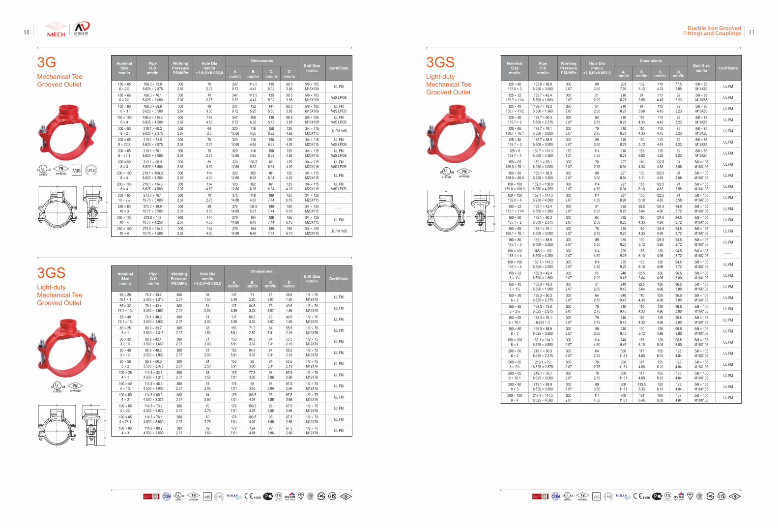
3GSLight-duty Mechanical Tee Grooved Outlet
NominalSize
mm/in
PipeO.D
mm/in
Working PressurePSI/MPa
Hole Diamm/in
+1.6,0/+0.063,0
DimensionsBolt Size
mm/in CertificateA
mm/inB
mm/inC
mm/inD
mm/in
65×2576.1×1
76.1×33.73.000×1.315
3002.07
381.50
1375.39
712.80
783.07
49.51.95
1/2×70M12X70 UL FM
65×3276.1×1¼
76.1×42.43.000×1.660
3002.07
512.00
1375.39
84.53.33
783.07
49.51.95
1/2×70M12X70 UL FM
65×4076.1×1½
76.1×48.33.000×1.900
3002.07
512.00
1375.39
84.53.33
783.07
49.51.95
1/2×70M12X70 UL FM
80×253×1
88.9×33.73.500×1.315
3002.07
381.50
1505.91
71.02.80
843.31
55.52.19
1/2×75M12X76 UL FM
80×323×1¼
88.9×42.43.500×1.660
3002.07
512.00
1505.91
84.53.33
843.31
55.52.19
1/2×75M12X76 UL FM
80×403×1½
88.9×48.33.500×1.900
3002.07
512.00
1505.91
84.53.33
843.31
55.52.19
1/2×75M12X76 UL FM
80×503×2
88.9×60.33.500×2.375
3002.07
642.50
1505.91
983.86
843.31
55.52.19
1/2×75M12X76 UL FM
100×254×1
114.3×33.74.500×1.315
3002.07
381.50
1787.01
77.53.05
983.86
67.52.66
1/2×75M12X76 UL FM
100×404×1½
114.3×48.34.500×1.900
3002.07
512.00
1787.01
883.46
983.86
67.52.66
1/2×75M12X76 UL FM
100×504×2
114.3×60.34.500×2.375
3002.07
642.50
1787.01
103.54.07
983.86
67.52.66
1/2×75M12X76 UL FM
100×654×2½
114.3×73.04.500×2.875
3002.07
702.75
1787.01
103.54.07
983.86
67.52.66
1/2×75M12X76 UL FM
100×654×76.1
114.3×76.14.500×3.000
3002.07
702.75
1787.01
103.54.07
983.86
67.52.66
1/2×75M12X76 UL FM
100×804×3
114.3×88.94.500×3.500
3002.07
893.50
1787.01
1244.88
983.86
67.52.66
1/2×75M12X76 UL FM
NominalSize
mm/in
PipeO.D
mm/in
Working PressurePSI/MPa
Hole Diamm/in
+1.6,0/+0.063,0
DimensionsBolt Size
mm/in CertificateA
mm/inB
mm/inC
mm/inD
mm/in
125×80133.0×3
133.0×88.95.250×3.500
3002.07
893.50
2037.99
1325.12
1104.33
77.53.05
5/8×85M16X85 UL FM
125×32139.7×11/4
139.7×42.45.500×1.660
3002.07
512.00
2108.27
913.58
1134.45
823.23
5/8×85M16X85 UL FM
125×40139.7×11/2
139.7×48.35.500×1.900
3002.07
512.00
2108.27
913.58
1134.45
823.23
5/8×85M16X85 UL FM
125×50139.7×2
139.7×60.35.500×2.375
3002.07
642.50
2108.27
1104.33
1134.45
823.23
5/8×85M16X85 UL FM
125×65139.7×76.1
139.7×76.15.500×3.000
3002.07
702.75
2108.27
1104.33
1134.45
823.23
5/8×85M16X85 UL FM
125×80139.7×3
139.7×88.95.500×3.500
3002.07
893.50
2108.27
1305.12
1134.45
823.23
5/8×85M16X85 UL FM
125×6139.7×4
139.7×114.35.500×4.500
1751.21
1144.50
2108.27
1536.02
1154.52
823.23
5/8×85M16X85 UL FM
150×65159.0×76.1
159.1×76.16.250×3.000
3002.07
702.75
2278.94
1104.33
122.54.83
913.58
5/8×105M16X108 UL FM
150×80159.0×88.9
159.1×88.96.250×3.500
3002.07
893.50
2278.94
1305.11
122.54.83
913.58
5/8×105M16X108 UL FM
150×100159.0×108.0
159.1×108.06.250×4.250
3002.07
1144.50
2278.94
1556.10
122.54.83
913.58
5/8×105M16X108 UL FM
150×100159.0×4
159.1×114.36.250×4.500
3002.07
1144.50
2278.94
1556.10
122.54.83
913.58
5/8×105M16X108 UL FM
150×32165.1×11/4
165.1×42.46.500×1.900
3002.07
512.00
2359.25
92.53.64
124.54.90
94.53.72
5/8×105M16X108 UL FM
150×50165.1×2
165.1×60.36.500×2.375
3002.07
642.50
2359.25
1104.33
124.54.90
94.53.72
5/8×105M16X108 UL FM
150×65165.1×76.1
165.1×76.16.500×3.000
3002.07
702.75
2359.25
1104.33
124.54.90
94.53.72
5/8×105M16X108 UL FM
150×80165.1×3
165.1×88.96.500×3.500
3002.07
893.50
2359.25
1305.12
124.54.90
94.53.72
5/8×105M16X108 UL FM
150×100165.1×4
165.1×1086.500×4.250
3002.07
1144.50
2359.25
1556.10
1264.96
94.53.72
5/8×105M16X108 ——
150×100165.1×4
165.1×114.36.500×4.500
3002.07
1144.50
2359.25
1556.10
1264.96
94.53.72
5/8×105M16X108 UL FM
150×326×1¼
168.3×42.46.500×1.660
3002.07
512.00
2409.45
92.53.64
1264.96
96.53.80
5/8×105M16X108 UL FM
150×406×1½
168.3×48.36.500×1.900
3002.07
512.00
2409.45
92.53.64
1264.96
96.53.80
5/8×105M16X108 UL FM
150×506×2
168.3×60.36.625×2.375
3002.07
642.50
2409.45
1104.33
1264.96
96.53.80
5/8×105M16X108 UL FM
150×656×2½
168.3×73.06.625×2.875
3002.07
702.75
2409.45
1104.33
1264.96
96.53.80
5/8×105M16X108 UL FM
150×656×76.1
168.3×76.16.625×3
3002.07
702.75
2409.45
1104.33
1264.96
96.53.80
5/8×105M16X108 UL FM
150×806×3
168.3×88.96.625×3.500
3002.07
893.50
2409.45
1305.12
1264.96
96.53.80
5/8×105M16X108 UL FM
150×1006×4
168.3×114.36.625×4.500
3002.07
1144.50
2409.45
1556.10
1285.04
96.53.80
5/8×105M16X108 UL FM
200×508×2
219.1×60.38.625×2.375
3002.07
642.50
30011.81
1174.60
1556.10
1234.84
5/8×105M16X108 UL FM
200×658×2½
219.1×738.625×2.875
3002.07
702.75
30011.81
1174.60
1556.10
1234.84
5/8×105M16X108 UL FM
200×658×76.1
219.1×76.18.625×3.000
3002.07
702.75
30011.81
1174.60
1556.10
1234.84
5/8×105M16X108 UL FM
200×808×3
219.1×88.98.625×3.500
3002.07
893.50
30011.81
135.55.33
1556.10
1234.84
5/8×105M16X108 UL FM
200×1008×4
219.1×114.38.625×4.500
3002.07
1144.50
30011.81
1646.46
1606.30
1234.84
5/8×105M16X108 UL FM
FMAPPROVED
3GMechanical Tee Grooved Outlet
NominalSize
mm/in
PipeO.D
mm/in
Working PressurePSI/MPa
Hole Diamm/in
+1.6,0/+0.063,0
DimensionsBolt Size
mm/in CertificateA
mm/inB
mm/inC
mm/inD
mm/in
150×656×2½
168.3×73.06.625×2.875
3002.07
702.75
2479.72
112.54.43
1355.32
98.53.88
5/8×105M16X108 UL FM
150×656×2½
168.3×76.16.625×3.000
3002.07
702.75
2479.72
112.54.43
1355.32
98.53.88
5/8×105M16X108 VdS LPCB
150×806×3
168.3×88.96.625×3.500
3002.07
893.50
2479.72
1325.20
1415.55
98.53.88
5/8×105M16X108
UL FM VdS LPCB
150×1006×4
168.3×114.36.625×4.500
3002.07
1144.50
2479.72
1606.30
1385.43
98.53.88
5/8×105M16X108
UL FM VdS LPCB
200×508×2
219.1×60.38.625×2.375
3002.07
642.5
32012.60
1184.65
1586.22
1254.92
3/4×115M20X115 UL FM VdS
200×658×21/2
219.1×73.08.625×2.875
3002.07
702.75
32012.60
1184.65
1586.22
1254.92
3/4×115M20X115
UL FM VdS LPCB
200×658×76.1
219.1×76.18.625×3.000
3002.07
702.75
32012.60
1184.65
1586.22
1254.92
3/4×115M20X115
UL FM VdS LPCB
200×808×3
219.1×88.98.625×3.500
3002.07
893.50
32012.60
136.55.37
1616.34
1254.92
3/4×115M20X115
UL FM VdS LPCB
200×1008×4
219.1×108.08.625×4.250
3002.07
1144.50
32012.60
1626.38
1616.34
1254.92
3/4×115M20X115 UL FM
200×1008×4
219.1×114.38.625×4.500
3002.07
1144.50
32012.60
1626.38
1616.34
1254.92
3/4×115M20X115
UL FM VdS LPCB
250×6510×2½
273.0×76.110.75×3.000
3002.07
702.75
37614.80
1184.65
1897.44
1556.10
3/4×120M20X115 ——
250×8010×3
273.0×88.910.75×3.500
3002.07
893.50
37614.80
136.55.37
1897.44
1556.10
3/4×120M20X115 ——
250×10010×4
273.0×10810.75×4.250
3002.07
1144.50
37614.80
1646.46
1897.44
1556.10
3/4×120M20X115 UL FM
250×10010×4
273.0×114.310.75×4.500
3002.07
1144.50
37614.80
1646.46
1897.44
1556.10
3/4×120M20X115 UL FM VdS
VdSFMAPPROVED LOSS
PRE
VENTIO
N CERTIFICATION
BOARD
3GSLight-duty Mechanical Tee Grooved Outlet
FMAPPROVED
VdS 1128 T STS2710Y44
WRASA P P R O V E D
P R O D U C TFM
APPROVED LOSS P
REVE
NTION CERTIFICATIO
N BO
ARD
CERTIF ICATIO
N
方
圆认证
BUREAU VERITASVdS 1128 T STS2710Y44
WRASA P P R O V E D
P R O D U C TFM
APPROVED LOSS P
REVE
NTION CERTIFICATIO
N BO
ARD
CERTIF ICATIO
N
方
圆认证
BUREAU VERITAS
Ductile Iron Grooved Fittings and Couplings 3130
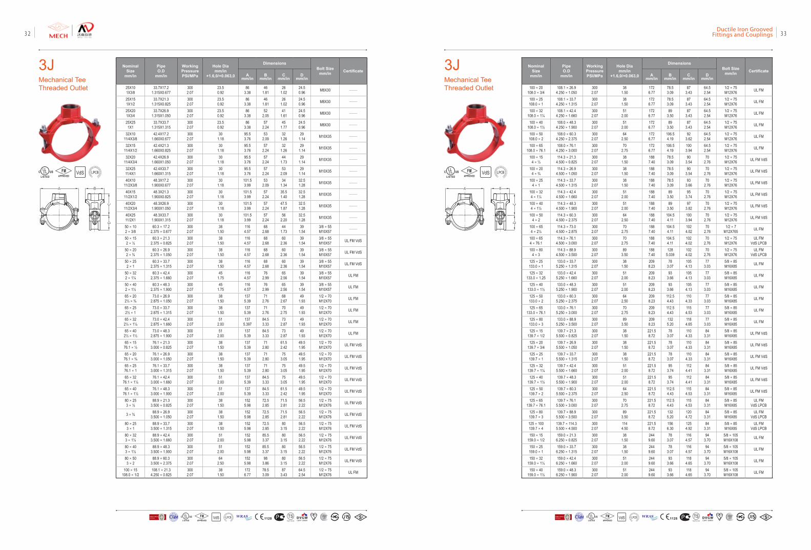
3JMechanical Tee Threaded Outlet
3JMechanical Tee Threaded Outlet
NominalSize
mm/in
PipeO.D
mm/in
Working PressurePSI/MPa
Hole Diamm/in
+1.6,0/+0.063,0
DimensionsBolt Size
mm/in CertificateA
mm/inB
mm/inC
mm/inD
mm/in
25X101X3/8
33.7X17.21.315X0.677
3002.07
23.50.92
863.38
461.81
261.02
24.50.96 M8X30 ——
25X151X1/2
33.7X21.31.315X0.825
3002.07
23.50.92
863.38
461.81
261.02
24.50.96 M8X30 ——
25X201X3/4
33.7X26.91.315X1.050
3002.07
23.50.92
863.38
522.05
411.61
24.50.96 M8X30 ——
25X251X1
33.7X33.71.315X1.315
3002.07
23.50.92
863.38
572.24
451.77
24.50.96 M8X30 ——
32X1011/4X3/8
42.4X17.21.660X0.677
3002.07
301.18
95.53.76
532.09
321.26
291.14 M10X35 ——
32X1511/4X1/2
42.4X21.31.660X0.825
3002.07
301.18
95.53.76
572.24
321.26
291.14 M10X35 ——
32X2011/4X3/4
42.4X26.91.660X1.050
3002.07
301.18
95.53.76
572.24
441.73
291.14 M10X35 ——
32X2511/4X1
42.4X33.71.660X1.315
3002.07
301.18
95.53.76
572.24
532.09
291.14 M10X35 ——
40X1011/2X3/8
48.3X17.21.900X0.677
3002.07
301.18
101.53.99
532.09
341.34
32.51.28 M10X35 ——
40X1511/2X1/2
48.3X21.31.900X0.825
3002.07
301.18
101.53.99
572.24
35.51.40
32.51.28 M10X35 ——
40X2011/2X3/4
48.3X26.91.900X1.050
3002.07
301.18
101.53.99
572.24
47.51.87
32.51.28 M10X35 ——
40X2511/2X1
48.3X33.71.900X1.315
3002.07
301.18
101.53.99
572.24
562.20
32.51.28 M10X35 ——
50×102×3/8
60.3×17.22.375×0.677
3002.07
381.50
1164.57
682.68
441.73
391.54
3/8×55M10X57 ——
50×152×½
60.3×21.32.375×0.825
3002.07
381.50
1164.57
682.68
602.36
391.54
3/8×55M10X57 UL FM VdS
50×202×¾
60.3×26.92.375×1.050
3002.07
381.50
1164.57
682.68
602.36
391.54
3/8×55M10X57 UL FM VdS
50×252×1
60.3×33.72.375×1.315
3002.07
381.50
1164.57
682.68
602.36
391.54
3/8×55M10X57 UL FM VdS
50×322×1¼
60.3×42.42.375×1.660
3002.07
451.75
1164.57
762.99
652.56
391.54
3/8×55M10X57 UL FM
50×402×1½
60.3×48.32.375×1.900
3002.07
451.75
1164.57
762.99
652.56
391.54
3/8×55M10X57 UL FM
65×202½×¾
73.0×26.92.875×1.050
3002.07
381.50
1375.39
712.76
682.67
491.93
1/2×70M12X70 UL FM
65×252½×1
73.0×33.72.875×1.315
3002.07
381.50
1375.39
712.76
702.75
491.93
1/2×70M12X70 UL FM
65×322½×1¼
73.0×42.42.875×1.660
3002.07
512.00
1375.397
84.53.33
732.87
491.93
1/2×70M12X70 UL FM
65×402½×1½
73.0×48.32.875×1.900
3002.07
512.00
1375.39
84.53.33
732.87
491.93
1/2×70M12X70 UL FM
65×1576.1×½
76.1×21.33.000×0.825
3002.07
381.50
1375.39
712.80
61.52.42
49.51.95
1/2×70M12X70 UL FM VdS
65×2076.1×¾
76.1×26.93.000×1.050
3002.07
381.50
1375.39
712.80
753.05
49.51.95
1/2×70M12X70 UL FM VdS
65×2576.1×1
76.1×33.73.000×1.315
3002.07
381.50
1375.39
712.80
753.05
49.51.95
1/2×70M12X70 UL FM VdS
65×3276.1×1¼
76.1×42.43.000×1.660
3002.07
512.00
1375.39
84.53.33
753.05
49.51.95
1/2×70M12X70 UL FM VdS
65×4076.1×1½
76.1×48.33.000×1.900
3002.07
512.00
1375.39
84.53.33
61.52.42
49.51.95
1/2×70M12X70 UL FM VdS
80×253×½
88.9×21.33.500×0.825
3002.07
381.50
1525.98
72.52.85
71.52.81
56.52.22
1/2×75M12X76 UL FM VdS
3×¾ 88.9×26.93.500×1.050
3002.07
381.50
1525.98
72.52.85
71.52.81
56.52.22
1/2×75M12X76 UL FM VdS
80×253×1
88.9×33.73.500×1.315
3002.07
381.50
1525.98
72.52.85
803.15
56.52.22
1/2×75M12X76 UL FM VdS
80×323×1¼
88.9×42.43.500×1.660
3002.07
512.00
1525.98
85.53.37
803.15
56.52.22
1/2×75M12X76 UL FM VdS
80×403×1½
88.9×48.33.500×1.900
3002.07
512.00
1525.98
85.53.37
803.15
56.52.22
1/2×75M12X76 UL FM VdS
80×503×2
88.9×60.33.500×2.375
3002.07
642.50
1525.98
983.86
803.15
56.52.22
1/2×75M12X76 UL FM VdS
100×15108.0×1/2
108.1×21.34.250×0.825
3002.07
381.50
1726.77
78.53.09
873.43
64.52.54
1/2×75M12X76 UL FM
NominalSize
mm/in
PipeO.D
mm/in
Working PressurePSI/MPa
Hole Diamm/in
+1.6,0/+0.063,0
DimensionsBolt Size
mm/in CertificateA
mm/inB
mm/inC
mm/inD
mm/in
100×20108.0×3/4
108.1×26.94.250×1.050
3002.07
381.50
1726.77
78.53.09
873.43
64.52.54
1/2×75M12X76 UL FM
100×25108.0×1
108.1×33.74.250×1.315
3002.07
381.50
1726.77
78.53.09
873.43
64.52.54
1/2×75M12X76 UL FM
100×32108.0×1¼
108.1×42.44.250×1.660
3002.07
512.00
1726.77
893.50
873.43
64.52.54
1/2×75M12X76 UL FM
100×40108.0×1½
108.0×48.34.250×1.900
3002.07
512.00
1726.77
893.50
873.43
64.52.54
1/2×75M12X76 UL FM
100×50108.0×2
108.0×60.34.250×2.375
3002.07
642.50
1726.77
106.54.19
923.62
64.52.54
1/2×75M12X76 UL FM
100×65108.0×76.1
108.0×76.14.250×3.000
3002.07
702.75
1726.77
106.54.19
1003.94
64.52.54
1/2×75M12X76 UL FM
100×154×½
114.3×21.34.500×0.825
3002.07
381.50
1887.40
78.53.09
903.54
702.76
1/2×75M12X76 UL FM VdS
100×204×¾
114.3×26.94.500×1.050
3002.07
381.50
1887.40
78.53.09
903.54
702.76
1/2×75M12X76 UL FM VdS
100×254×1
114.3×33.74.500×1.315
3002.07
381.50
1887.40
78.53.09
933.66
702.76
1/2×75M12X76 UL FM VdS
100×324×1¼
114.3×42.44.500×1.660
3002.07
512.00
1887.40
893.50
953.74
702.76
1/2×75M12X76 UL FM VdS
100×404×1½
114.3×48.34.500×1.900
3002.07
512.00
1887.40
893.50
973.82
702.76
1/2×75M12X76 UL FM VdS
100×504×2
114.3×60.34.500×2.375
3002.07
642.50
1887.40
104.54.11
1003.94
702.76
1/2×75M12X76 UL FM VdS
100×654×2½
114.3×73.04.500×2.875
3002.07
702.75
1887.40
104.54.11
1024.02
702.76
1/2×7M12X765 UL FM
100×654×76.1
114.3×76.14.500×3.000
3002.07
702.75
1887.40
104.54.11
1024.02
702.76
1/2×75M12X76
UL FM VdS LPCB
100×804×3
114.3×88.94.500×3.500
3002.07
893.50
1887.40
1285.039
1024.02
702.76
1/2×75M12X76
UL FM VdS LPCB
125×25133.0×1
133.0×33.75.250×1.315
3002.07
381.50
2098.23
783.07
1054.13
773.03
5/8×85M16X85 UL FM
125×32133.0×1.25
133.0×42.45.250×1.660
3002.07
512.00
2098.23
933.66
1054.13
773.03
5/8×85M16X85 UL FM
125×40133.0×1½
133.0×48.35.250×1.900
3002.07
512.00
2098.23
933.66
1054.13
773.03
5/8×85M16X85 UL FM
125×50133.0×2
133.0×60.35.250×2.375
3002.07
642.50
2098.23
112.54.43
1104.33
773.03
5/8×85M16X85 UL FM
125×65133.0×76.1
133.0×76.15.250×3.000
3002.07
702.75
2098.23
112.54.43
1154.53
773.03
5/8×85M16X85 UL FM
125×80133.0×3
133.0×88.95.250×3.500
3002.07
893.50
2098.23
1325.20
1184.65
773.03
5/8×85M16X85 UL FM
125×15139.7×1/2
139.7×21.35.500×0.825
3002.07
381.50
221.58.72
783.07
1104.33
843.31
5/8×85M16X85 UL FM VdS
125×20139.7×3/4
139.7×26.95.500×1.050
3002.07
381.50
221.58.72
783.07
1104.33
843.31
5/8×85M16X85 UL FM VdS
125×25139.7×1
139.7×33.75.500×1.315
3002.07
381.50
221.58.72
783.07
1104.33
843.31
5/8×85M16X85 UL FM VdS
125×32139.7×1¼
139.7×42.45.500×1.660
3002.07
512.00
221.58.72
953.74
1124.41
843.31
5/8×85M16X85 UL FM VdS
125×40139.7×1½
139.7×48.35.500×1.900
3002.07
512.00
221.58.72
953.74
1124.41
843.31
5/8×85M16X85 UL FM VdS
125×50139.7×2
139.7×60.35.500×2.375
3002.07
642.50
221.58.72
112.54.43
1154.53
843.31
5/8×85M16X85 UL FM VdS
125×65139.7×76.1
139.7×76.15.500×3.000
3002.07
702.75
221.58.72
112.54.43
1154.53
843.31
5/8×85M16X85
UL FM VdS LPCB
125×80139.7×3
139.7×88.95.500×3.500
3002.07
893.50
221.58.72
1325.20
1204.72
843.31
5/8×85M16X85
UL FM VdS LPCB
125×100139.7×4
139.7×114.35.500×4.500
3002.07
1144.50
221.58.72
1566.30
1254.92
843.31
5/8×85M16X85
UL FM VdS LPCB
150×15159.0×1/2
159.0×21.36.250×0.825
3002.07
381.50
2449.60
783.07
1164.57
943.70
5/8×105M16X108 UL FM
150×25159.0×1
159.0×33.76.250×1.315
3002.07
381.50
2449.60
783.07
1164.57
943.70
5/8×105M16X108 UL FM
150×32159.0×1¼
159.0×42.46.250×1.660
3002.07
512.00
2449.60
933.66
1184.65
943.70
5/8×105M16X108 UL FM
150×40159.0×1½
159.0×48.36.250×1.900
3002.07
512.00
2449.60
933.66
1184.65
943.70
5/8×105M16X108 UL FM
VdSFMAPPROVED LOSS
PRE
VENTIO
N CERTIFICATION
BOARD
VdSFMAPPROVED LOSS
PRE
VENTIO
N CERTIFICATION
BOARD
VdS 1128 T STS2710Y44
WRASA P P R O V E D
P R O D U C TFM
APPROVED LOSS P
REVE
NTION CERTIFICATIO
N BO
ARD
CERTIF ICATIO
N
方
圆认证
BUREAU VERITASVdS 1128 T STS2710Y44
WRASA P P R O V E D
P R O D U C TFM
APPROVED LOSS P
REVE
NTION CERTIFICATIO
N BO
ARD
CERTIF ICATIO
N
方
圆认证
BUREAU VERITAS
Ductile Iron Grooved Fittings and Couplings 3332
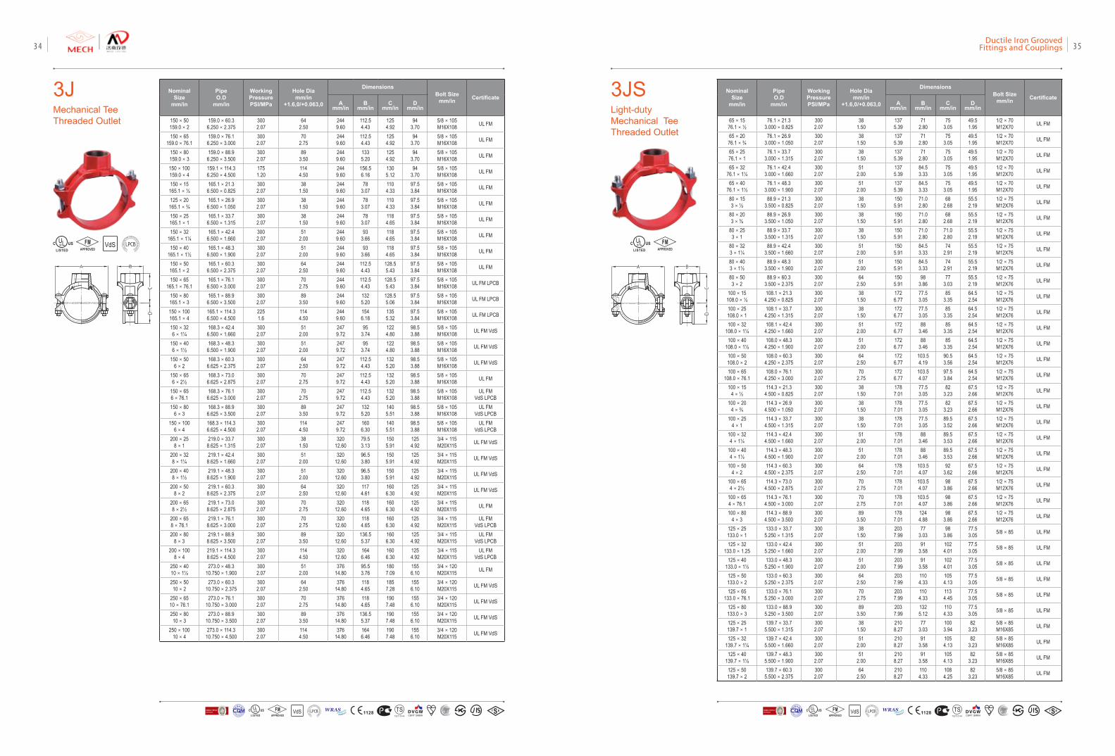
NominalSize
mm/in
PipeO.D
mm/in
Working PressurePSI/MPa
Hole Diamm/in
+1.6,0/+0.063,0
Dimensions Bolt Size
mm/in CertificateA
mm/inB
mm/inC
mm/inD
mm/in
150×50159.0×2
159.0×60.36.250×2.375
3002.07
642.50
2449.60
112.54.43
1254.92
943.70
5/8×105M16X108 UL FM
150×65159.0×76.1
159.0×76.16.250×3.000
3002.07
702.75
2449.60
112.54.43
1254.92
943.70
5/8×105M16X108 UL FM
150×80159.0×3
159.0×88.96.250×3.500
3002.07
893.50
2449.60
1335.20
1254.92
943.70
5/8×105M16X108 UL FM
150×100159.0×4
159.1×114.36.250×4.500
1751.20
1144.50
2449.60
156.56.16
1305.12
943.70
5/8×105M16X108 UL FM
150×15165.1×½
165.1×21.36.500×0.825
3002.07
381.50
2449.60
783.07
1104.33
97.53.84
5/8×105M16X108 UL FM
125×20165.1×¾
165.1×26.96.500×1.050
3002.07
381.50
2449.60
783.07
1104.33
97.53.84
5/8×105M16X108 UL FM
150×25165.1×1
165.1×33.76.500×1.315
3002.07
381.50
2449.60
783.07
1184.65
97.53.84
5/8×105M16X108 UL FM
150×32165.1×1¼
165.1×42.46.500×1.660
3002.07
512.00
2449.60
933.66
1184.65
97.53.84
5/8×105M16X108 UL FM
150×40165.1×1½
165.1×48.36.500×1.900
3002.07
512.00
2449.60
933.66
1184.65
97.53.84
5/8×105M16X108 UL FM
150×50165.1×2
165.1×60.36.500×2.375
3002.07
642.50
2449.60
112.54.43
128.55.43
97.53.84
5/8×105M16X108 UL FM
150×65165.1×76.1
165.1×76.16.500×3.000
3002.07
702.75
2449.60
112.54.43
128.55.43
97.53.84
5/8×105M16X108 UL FM LPCB
150×80165.1×3
165.1×88.96.500×3.500
3002.07
893.50
2449.60
1325.20
128.55.06
97.53.84
5/8×105M16X108 UL FM LPCB
150×100165.1×4
165.1×114.36.500×4.500
2251.6
1144.50
2449.60
1546.18
1355.32
97.53.84
5/8×105M16X108 UL FM LPCB
150×326×1¼
168.3×42.46.500×1.660
3002.07
512.00
2479.72
953.74
1224.80
98.53.88
5/8×105M16X108 UL FM VdS
150×406×1½
168.3×48.36.500×1.900
3002.07
512.00
2479.72
953.74
1224.80
98.53.88
5/8×105M16X108 UL FM VdS
150×506×2
168.3×60.36.625×2.375
3002.07
642.50
2479.72
112.54.43
1325.20
98.53.88
5/8×105M16X108 UL FM VdS
150×656×2½
168.3×73.06.625×2.875
3002.07
702.75
2479.72
112.54.43
1325.20
98.53.88
5/8×105M16X108 UL FM
150×656×76.1
168.3×76.16.625×3.000
3002.07
702.75
2479.72
112.54.43
1325.20
98.53.88
5/8×105M16X108
UL FM VdS LPCB
150×806×3
168.3×88.96.625×3.500
3002.07
893.50
2479.72
1325.20
1405.51
98.53.88
5/8×105M16X108
UL FM VdS LPCB
150×1006×4
168.3×114.36.625×4.500
3002.07
1144.50
2479.72
1606.30
1405.51
98.53.88
5/8×105M16X108
UL FM VdS LPCB
200×258×1
219.0×33.78.625×1.315
3002.07
381.50
32012.60
79.53.13
1505.91
1254.92
3/4×115M20X115 UL FM VdS
200×328×1¼
219.1×42.48.625×1.660
3002.07
512.00
32012.60
96.53.80
1505.91
1254.92
3/4×115M20X115 UL FM VdS
200×408×1½
219.1×48.38.625×1.900
3002.07
512.00
32012.60
96.53.80
1505.91
1254.92
3/4×115M20X115 UL FM VdS
200×508×2
219.1×60.38.625×2.375
3002.07
642.50
32012.60
1174.61
1606.30
1254.92
3/4×115M20X115 UL FM VdS
200×658×2½
219.1×73.08.625×2.875
3002.07
702.75
32012.60
1184.65
1606.30
1254.92
3/4×115M20X115 UL FM
200×658×76.1
219.1×76.18.625×3.000
3002.07
702.75
32012.60
1184.65
1606.30
1254.92
3/4×115M20X115
UL FMVdS LPCB
200×808×3
219.1×88.98.625×3.500
3002.07
893.50
32012.60
136.55.37
1606.30
1254.92
3/4×115M20X115
UL FMVdS LPCB
200×1008×4
219.1×114.38.625×4.500
3002.07
1144.50
32012.60
1646.46
1606.30
1254.92
3/4×115M20X115
UL FMVdS LPCB
250×4010×1½
273.0×48.310.750×1.900
3002.07
512.00
37614.80
95.53.76
1807.09
1556.10
3/4×120M20X115 UL FM
250×5010×2
273.0×60.310.750×2.375
3002.07
642.50
37614.80
1184.65
1857.28
1556.10
3/4×120M20X115 UL FM VdS
250×6510×76.1
273.0×76.110.750×3.000
3002.07
702.75
37614.80
1184.65
1907.48
1556.10
3/4×120M20X115 UL FM VdS
250×8010×3
273.0×88.910.750×3.500
3002.07
893.50
37614.80
136.55.37
1907.48
1556.10
3/4×120M20X115 UL FM VdS
250×10010×4
273.0×114.310.750×4.500
3002.07
1144.50
37614.80
1646.46
1907.48
1556.10
3/4×120M20X115 UL FM VdS
NominalSize
mm/in
PipeO.D
mm/in
Working PressurePSI/MPa
Hole Diamm/in
+1.6,0/+0.063,0
DimensionsBolt Size
mm/in CertificateA
mm/inB
mm/inC
mm/inD
mm/in
65×1576.1×½
76.1×21.33.000×0.825
3002.07
381.50
1375.39
712.80
753.05
49.51.95
1/2×70M12X70 UL FM
65×2076.1×¾
76.1×26.93.000×1.050
3002.07
381.50
1375.39
712.80
753.05
49.51.95
1/2×70M12X70 UL FM
65×2576.1×1
76.1×33.73.000×1.315
3002.07
381.50
1375.39
712.80
753.05
49.51.95
1/2×70M12X70 UL FM
65×3276.1×1¼
76.1×42.43.000×1.660
3002.07
512.00
1375.39
84.53.33
753.05
49.51.95
1/2×70M12X70 UL FM
65×4076.1×1½
76.1×48.33.000×1.900
3002.07
512.00
1375.39
84.53.33
753.05
49.51.95
1/2×70M12X70 UL FM
80×153×½
88.9×21.33.500×0.825
3002.07
381.50
1505.91
71.02.80
682.68
55.52.19
1/2×75M12X76 UL FM
80×203×¾
88.9×26.93.500×1.050
3002.07
381.50
1505.91
71.02.80
682.68
55.52.19
1/2×75M12X76 UL FM
80×253×1
88.9×33.73.500×1.315
3002.07
381.50
1505.91
71.02.80
71.02.80
55.52.19
1/2×75M12X76 UL FM
80×323×1¼
88.9×42.43.500×1.660
3002.07
512.00
1505.91
84.53.33
742.91
55.52.19
1/2×75M12X76 UL FM
80×403×1½
88.9×48.33.500×1.900
3002.07
512.00
1505.91
84.53.33
742.91
55.52.19
1/2×75M12X76 UL FM
80×503×2
88.9×60.33.500×2.375
3002.07
642.50
1505.91
983.86
773.03
55.52.19
1/2×75M12X76 UL FM
100×15108.0×½
108.1×21.34.250×0.825
3002.07
381.50
1726.77
77.53.05
853.35
64.52.54
1/2×75M12X76 UL FM
100×25108.0×1
108.1×33.74.250×1.315
3002.07
381.50
1726.77
77.53.05
853.35
64.52.54
1/2×75M12X76 UL FM
100×32108.0×1¼
108.1×42.44.250×1.660
3002.07
512.00
1726.77
883.46
853.35
64.52.54
1/2×75M12X76 UL FM
100×40108.0×1½
108.0×48.34.250×1.900
3002.07
512.00
1726.77
883.46
853.35
64.52.54
1/2×75M12X76 UL FM
100×50108.0×2
108.0×60.34.250×2.375
3002.07
642.50
1726.77
103.54.19
90.53.56
64.52.54
1/2×75M12X76 UL FM
100×65108.0×76.1
108.0×76.14.250×3.000
3002.07
702.75
1726.77
103.54.07
97.53.84
64.52.54
1/2×75M12X76 UL FM
100×154×½
114.3×21.34.500×0.825
3002.07
381.50
1787.01
77.53.05
823.23
67.52.66
1/2×75M12X76 UL FM
100×204×¾
114.3×26.94.500×1.050
3002.07
381.50
1787.01
77.53.05
823.23
67.52.66
1/2×75M12X76 UL FM
100×254×1
114.3×33.74.500×1.315
3002.07
381.50
1787.01
77.53.05
89.53.52
67.52.66
1/2×75M12X76 UL FM
100×324×1¼
114.3×42.44.500×1.660
3002.07
512.00
1787.01
883.46
89.53.53
67.52.66
1/2×75M12X76 UL FM
100×404×1½
114.3×48.34.500×1.900
3002.07
512.00
1787.01
883.46
89.53.53
67.52.66
1/2×75M12X76 UL FM
100×504×2
114.3×60.34.500×2.375
3002.07
642.50
1787.01
103.54.07
923.62
67.52.66
1/2×75M12X76 UL FM
100×654×2½
114.3×73.04.500×2.875
3002.07
702.75
1787.01
103.54.07
983.86
67.52.66
1/2×75M12X76 UL FM
100×654×76.1
114.3×76.14.500×3.000
3002.07
702.75
1787.01
103.54.07
983.86
67.52.66
1/2×75M12X76 UL FM
100×804×3
114.3×88.94.500×3.500
3002.07
893.50
1787.01
1244.88
983.86
67.52.66
1/2×75M12X76 UL FM
125×25133.0×1
133.0×33.75.250×1.315
3002.07
381.50
2037.99
773.03
983.86
77.53.05 5/8×85 UL FM
125×32133.0×1.25
133.0×42.45.250×1.660
3002.07
512.00
2037.99
913.58
1024.01
77.53.05 5/8×85 UL FM
125×40133.0×1½
133.0×48.35.250×1.900
3002.07
512.00
2037.99
913.58
1024.01
77.53.05 5/8×85 UL FM
125×50133.0×2
133.0×60.35.250×2.375
3002.07
642.50
2037.99
1104.33
1054.13
77.53.05 5/8×85 UL FM
125×65133.0×76.1
133.0×76.15.250×3.000
3002.07
702.75
2037.99
1104.33
1134.45
77.53.05 5/8×85 UL FM
125×80133.0×3
133.0×88.95.250×3.500
3002.07
893.50
2037.99
1325.12
1104.33
77.53.05 5/8×85 UL FM
125×25139.7×1
139.7×33.75.500×1.315
3002.07
381.50
2108.27
773.03
1003.94
823.23
5/8×85M16X85 UL FM
125×32139.7×1¼
139.7×42.45.500×1.660
3002.07
512.00
2108.27
913.58
1054.13
823.23
5/8×85M16X85 UL FM
125×40139.7×1½
139.7×48.35.500×1.900
3002.07
512.00
2108.27
913.58
1054.13
823.23
5/8×85M16X85 UL FM
125×50139.7×2
139.7×60.35.500×2.375
3002.07
642.50
2108.27
1104.33
1084.25
823.23
5/8×85M16X85 UL FM
3JMechanical Tee Threaded Outlet
VdSFMAPPROVED LOSS
PRE
VENTIO
N CERTIFICATION
BOARD
3JSLight-duty Mechanical Tee Threaded Outlet
FMAPPROVED
VdS 1128 T STS2710Y44
WRASA P P R O V E D
P R O D U C TFM
APPROVED LOSS P
REVE
NTION CERTIFICATIO
N BO
ARD
CERTIF ICATIO
N
方
圆认证
BUREAU VERITASVdS 1128 T STS2710Y44
WRASA P P R O V E D
P R O D U C TFM
APPROVED LOSS P
REVE
NTION CERTIFICATIO
N BO
ARD
CERTIF ICATIO
N
方
圆认证
BUREAU VERITAS
Ductile Iron Grooved Fittings and Couplings 3534
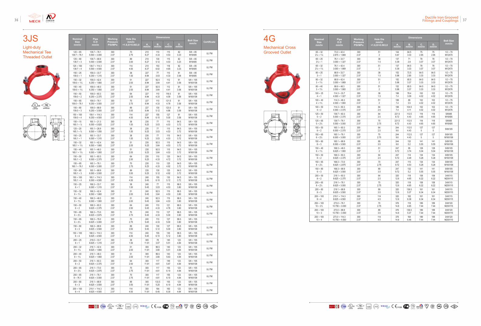
NominalSize
mm/in
PipeO.D
mm/in
Working PressurePSI/MPa
Hole Diamm/in
+1.6,0/+0.063,0
Dimensions Bolt Size
mm/in CertificateA
mm/inB
mm/inC
mm/inD
mm/in
125×65139.7×76.1
139.7×76.15.500×3.000
3002.07
702.75
2108.27
1104.33
1154.53
823.23
5/8×85M16X85 UL FM
125×80139.7×3
139.7×88.95.500×3.500
3002.07
893.50
2108.27
1305.12
1154.53
823.23
5/8×85M16X85 UL FM
125×100139.7×4
139.7×114.35.500×4.500
3002.07
1144.50
2108.27
1536.02
1184.65
823.23
5/8×85M16X85 UL FM
150×25159.0×1
159.0×33.76.250×1.315
3002.07
381.50
2278.94
773.03
1104.33
913.58
5/8×85M16X85 UL FM
150×32159.0×1¼
159.0×42.46.250×1.660
3002.07
512.00
2278.94
92.53.64
1124.41
913.58
5/8×105M16X108 UL FM
150×40159.0×1½
159.0×48.36.250×1.900
3002.07
512.00
2278.94
92.53.64
1124.41
913.58
5/8×105M16X108 UL FM
150×50159.0×2
159.0×60.36.250×2.375
3002.07
642.50
2278.94
1104.33
116.54.59
913.58
5/8×105M16X108 UL FM
150×65159.0×76.1
159.0×76.16.250×3.000
3002.07
702.75
2278.94
1104.33
121.54.78
913.58
5/8×105M16X108 UL FM
150×80159.0×3
159.0×88.96.250×3.500
3002.07
893.50
2278.94
1305.12
123.54.86
913.58
5/8×105M16X108 UL FM
150×100159.0×4
159.1×114.36.250×4.500
3002.07
1144.50
2278.94
1556.10
1275.00
913.58
5/8×105M16X108 UL FM
150×15165.1×½
165.1×21.36.500×0.825
3002.07
381.50
2359.25
773.03
1154.53
94.53.72
5/8×105M16X108 UL FM
125×20165.1×¾
165.1×26.96.500×1.050
3002.07
381.50
2359.25
773.03
1154.53
94.53.72
5/8×105M16X108 UL FM
150×25165.1×1
165.1×33.76.500×1.315
3002.07
381.50
2359.25
773.03
1154.53
94.53.72
5/8×105M16X108 UL FM
150×32165.1×1¼
165.1×42.46.500×1.660
3002.07
512.00
2359.25
92.53.64
1154.53
94.53.72
5/8×105M16X108 UL FM
150×40165.1×1½
165.1×48.36.500×1.900
3002.07
512.00
2359.25
92.53.64
1154.53
94.53.72
5/8×105M16X108 UL FM
150×50165.1×2
165.1×60.36.500×2.375
3002.07
642.50
2359.25
1104.33
1204.72
94.53.72
5/8×105M16X108 UL FM
150×65165.1×76.1
165.1×76.16.500×3.000
3002.07
702.75
2359.25
1104.33
1254.92
94.53.72
5/8×105M16X108 UL FM
150×80165.1×3
165.1×88.96.500×3.500
3002.07
893.50
2359.25
1305.12
1254.92
94.53.72
5/8×105M16X108 UL FM
150×100165.1×4
165.1×114.36.500×4.500
3002.07
1144.50
2409.45
1556.10
1305.12
94.53.72
5/8×105M16X108 UL FM
150×256×1
168.3×33.76.500×1.315
3002.07
381.50
2409.45
773.03
1154.53
96.53.80
5/8×105M16X108 UL FM
150×326×1¼
168.3×42.46.500×1.660
3002.07
512.00
2409.45
92.53.64
1154.53
96.53.80
5/8×105M16X108 UL FM
150×406×1½
168.3×48.36.500×1.900
3002.07
512.00
2409.45
92.53.64
1154.53
96.53.80
5/8×105M16X108 UL FM
150×506×2
168.3×60.36.625×2.375
3002.07
642.50
2409.45
1104.33
1214.76
96.53.80
5/8×105M16X108 UL FM
150×656×2½
168.3×73.06.625×2.875
3002.07
702.75
2409.45
1104.33
1275.00
96.53.80
5/8×105M16X108 UL FM
150×656×2½
168.3×76.06.625×3.000
3002.07
702.75
2409.45
1104.33
1275.00
96.53.80
5/8×105M16X108 ——
150×806×3
168.3×88.96.625×3.500
3002.07
893.50
2409.45
1305.12
1275.00
96.53.80
5/8×105M16X108 UL FM
150×1006×4
168.3×114.36.625×4.500
3002.07
1144.50
2409.45
1556.10
1305.12
96.53.80
5/8×105M16X108 UL FM
200×258×1
219.0×33.78.625×1.315
3002.07
381.50
30011.81
783.07
1405.51
1234.84
5/8×105M16X108 UL FM
200×328×1¼
219.1×42.48.625×1.660
3002.07
512.00
30011.81
96.53.80
1405.51
1234.84
5/8×105M16X108 UL FM
200×408×1½
219.1×48.38.625×1.900
3002.07
512.00
30011.81
96.53.80
1435.63
1234.84
5/8×105M16X108 UL FM
200×508×2
219.1×60.38.625×2.375
3002.07
642.50
30011.81
1174.61
1495.87
1234.84
5/8×105M16X108 UL FM
200×658×2½
219.1×73.08.625×2.875
3002.07
702.75
30011.81
1174.61
1556.10
1234.84
5/8×105M16X108 UL FM
200×658×76.1
219.1×76.18.625×3.000
3002.07
702.75
30011.81
1174.61
1556.10
1234.84
5/8×105M16X108 UL FM
200×808×3
219.1×88.98.625×3.500
3002.07
893.50
30011.81
133.55.25
1556.10
1234.84
5/8×105M16X108 UL FM
200×1008×4
219.1×114.38.625×4.500
3002.07
1144.50
30011.81
1646.45
1606.30
1234.84
5/8×105M16X108 UL FM
3JSLight-duty Mechanical Tee Threaded Outlet
FMAPPROVED
4GMechanical Cross Grooved Outlet
NominalSize
mm/in
PipeO.D
mm/in
Working PressurePSI/MPa
Hole Diamm/in
+1.6,0/+0.063,0
DimensionsBolt Size
mm/inAmm/in
Bmm/in
Cmm/in
Dmm/in
65×322½×1¼
73.0×42.42.875×1.669
3002.07
512
1445.67
84.53.33
752.95
752.95
1/2×70M12X70
65×252½×1
76.1×33.73.000×1.327
3002.07
381.5
1375.39
712.8
783.07
783.07
1/2×70M12X70
65×322½×1¼
76.1×42.43.000×1.669
3002.07
512
1375.39
84.53.33
783.07
783.07
1/2×70M12X70
80×253×1
88.9×33.73.500×1.327
3002.07
381.5
1525.98
72.52.85
84.53.33
84.53.33
1/2×75M12X76
80×323×1¼
88.9×42.43.500×1.669
3002.07
512
1525.98
85.53.37
84.53.33
84.53.33
1/2×75M12X76
80×403×1½
88.9×48.33.500×1.900
3002.07
512
1525.98
85.53.37
84.53.33
84.53.33
1/2×75M12X76
100×254×1
114.3×33.74.500×1.327
3002.07
381.5
1887.4
78.43.09
1024.02
1024.02
1/2×75M12X76
100×404×1½
114.3×48.34.500×1.900
3002.07
512
1887.4
893.5
1024.02
1024.02
1/2×75M12X76
100×504×2
114.3×60.34.500×2.375
3002.07
642.5
1887.4
104.54.11
1024.02
1024.02
1/2×75M12X76
125×505×2
139.7×60.35.500×2.375
3002.07
642.5
221.58.72
112.54.43
1184.65
1184.65
5/8X85M16X85
125×655×2½
139.7×76.15.500×3.000
3002.07
702.75
221.58.72
112.54.43
1184.65
1184.65
5/8X85M16X85
150×506×2
165.1×60.36.500×2.375
3002.07
642.5
2449.6
112.54.43
1275
1275 5/8X105
150×656×2½
165.1×76.16.500×3.000
3002.07
702.75
2449.6
112.54.43
1275
1275
5/8X105M16X108
150×806×3
165.1×88.96.500×3.500
3002.07
893.5
2449.6
1325.2
1415.55
1415.55
5/8X105M16X108
150×406×1½
168.3×48.36.625×1.900
3002.07
512
2479.72
953.74
1285.04
1285.04
5/8X105M16X108
150×506×2
168.3×60.36.625×2.375
3002.07
642.5
2479.72
1144.49
1345.28
1345.28
5/8X105M16X108
150×656×2½
168.3×73.06.625×2.875
3002.07
702.75
2479.72
1154.53
1345.28
1345.28
5/8X105M16X108
150×806×3
168.3×88.96.625×3.500
3002.07
893.5
2479.72
1325.2
1415.55
1415.55
5/8X105M16X108
200×508×2
219.1×60.38.625×2.375
3002.07
642.5
32012.6
1184.65
1586.22
1586.22
3/4X115M20X115
200×658×2½
219.1×76.18.625×3.000
3002.07
702.75
32012.6
1184.65
1586.22
1586.22
3/4X115M20X115
200×808×3
219.1×88.98.625×3.500
3002.07
893.5
32012.6
136.55.37
1616.34
1616.34
3/4X115M20X115
200×1008×4
219.1×114.38.625×4.500
3002.07
1144.5
32012.6
1626.38
1616.34
1616.34
3/4X115M20X115
250×10010×2½
273.0×76.110.750×3.000
3002.07
702.75
37614.8
1184.65
1897.44
1897.44
3/4X120M20X115
250×10010×3
273.0×88.910.750×3.500
3002.07
893.5
37614.8
136.55.37
1897.44
1897.44
3/4X120M20X115
250×10010×4
273.0×114.310.750×4.500
3002.07
1144.5
37614.8
1646.46
1897.44
1897.44
3/4X120M20X115
VdS 1128 T STS2710Y44
WRASA P P R O V E D
P R O D U C TFM
APPROVED LOSS P
REVE
NTION CERTIFICATIO
N BO
ARD
CERTIF ICATIO
N
方
圆认证
BUREAU VERITASVdS 1128 T STS2710Y44
WRASA P P R O V E D
P R O D U C TFM
APPROVED LOSS P
REVE
NTION CERTIFICATIO
N BO
ARD
CERTIF ICATIO
N
方
圆认证
BUREAU VERITAS
Ductile Iron Grooved Fittings and Couplings 3736
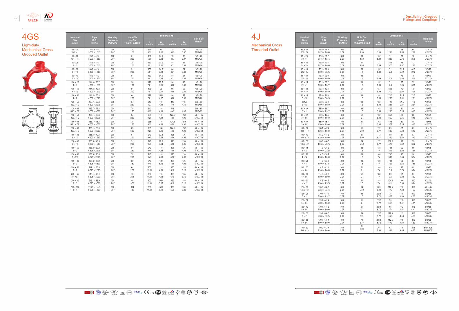
4GSLight-duty Mechanical Cross Grooved Outlet
NominalSize
mm/in
PipeO.D
mm/in
Working PressurePSI/MPa
Hole Diamm/in
+1.6,0/+0.063,0
Dimensions Bolt Size
mm/inAmm/in
Bmm/in
Cmm/in
Dmm/in
65×2576.1×1
76.1×33.73.000×1.315
3002.07
381.50
1375.39
712.80
783.07
783.07
1/2×70M12X70
65×3276.1×1¼
76.1×42.43.000×1.660
3002.07
512.00
1375.39
84.53.33
783.07
783.07
1/2×70M12X70
80×253×1
88.9×33.73.500×1.315
3002.07
381.50
1505.91
71.02.80
843.31
843.31
1/2×70M12X76
80×323×1¼
88.9×42.43.500×1.660
3002.07
512.00
1505.91
84.53.33
843.31
843.31
1/2×70M12X76
80×403×1½
88.9×48.33.500×1.900
3002.07
512.00
1505.91
84.53.33
843.31
843.31
1/2×70M12X76
100×254×1
114.3×33.74.500×1.315
3002.07
381.50
1787.01
77.53.05
983.86
983.86
1/2×70M12X76
100×404×1½
114.3×48.34.500×1.900
3002.07
512.00
1787.01
883.46
983.86
983.86
1/2×70M12X76
100×504×2
114.3×60.34.500×2.375
3002.07
642.50
1787.01
103.54.07
983.86
983.86
1/2×70M12X76
125×50139.7×2
139.7×60.35.500×2.375
3002.07
642.50
2108.27
1104.33
1134.45
1134.45
5/8×85M16X85
125×65139.7×76.1
139.7×76.15.500×3.000
3002.07
702.75
2108.27
1104.33
1134.45
1134.45
5/8×85M16X85
150×50165.1×2
165.1×60.36.500×2.375
3002.07
642.50
2359.25
1104.33
124.54.90
124.54.90
5/8×105M16X108
150×65165.1×76.1
165.1×76.16.500×3.000
3002.07
702.75
2359.25
1104.33
124.54.90
124.54.90
5/8×105M16X108
150×80165.1×3
165.1×88.96.500×3.500
3002.07
893.50
2359.25
1305.12
124.54.90
124.54.90
5/8×105M16X108
150×326×1¼
168.3×42.46.500×1.660
3002.07
512.00
2409.45
92.53.64
1264.96
1264.96
5/8×105M16X108
150×406×1½
168.3×48.36.500×1.900
3002.07
512.00
2409.45
92.53.64
1264.96
1264.96
5/8×105M16X108
150×506×2
168.3×60.36.625×2.375
3002.07
642.50
2409.45
1104.33
1264.96
1264.96
5/8×105M16X108
150×656×2½
168.3×73.06.625×2.875
3002.07
702.75
2409.45
1104.33
1264.96
1264.96
5/8×105M16X108
150×806×3
168.3×88.96.625×3.500
3002.07
893.50
2409.45
1305.12
1264.96
1264.96
5/8×105M16X108
200×508×2
219.1×60.38.625×2.375
3002.07
642.50
30011.81
1154.53
1556.10
1556.10
5/8×105M16X108
200×658×76.1
219.1×76.18.625×3.000
3002.07
702.75
30011.81
1154.53
1556.10
1556.10
5/8×105M16X108
200×808×3
219.1×88.98.625×3.500
3002.07
893.50
30011.81
133.55.25
1556.10
1556.10
5/8×105M16X108
200×1008×4
219.1×114.38.625×4.500
3002.07
1144.50
30011.81
159.56.29
1606.30
1606.30
5/8×105M16X108
4JMechanical Cross Threaded Outlet
NominalSize
mm/in
PipeO.D
mm/in
Working PressurePSI/MPa
Hole Diamm/in
+1.6,0/+0.063,0
DimensionsBolt Size
mm/inAmm/in
Bmm/in
Cmm/in
Dmm/in
65×202½×¾
73.0×26.92.875×1.050
3002.07
381.50
1375.39
712.80
682.68
682.68
1/2×70M12X70
65×252½×1
73.0×33.72.875×1.315
3002.07
381.50
1375.39
712.80
702.76
702.76
1/2×70M12X70
65×322½×1¼
73.0×42.42.875×1.660
3002.07
512.00
1375.39
84.53.33
732.87
732.87
1/2×70M12X70
65×152½×½
76.1×21.33.000×0.825
3002.07
381.5
1375.39
712.8
61.52.42
61.52.42
1/2X70M12X70
65×202½×¾
76.1×26.93.000×1.059
3002.07
381.5
1375.39
712.8
753.05
753.05
1/2X70M12X70
65×252½×1
76.1×33.73.000×1.327
3002.07
381.5
1375.39
712.8
753.05
753.05
1/2X70M12X70
65×322½×1¼
76.1×42.43.000×1.669
3002.07
512
1375.39
84.53.33
753.05
753.05
1/2X70M12X70
80×153×½
88.9×21.33.500×0.825
3002.07
381.5
1525.98
72.52.85
71.52.81
71.52.81
1/2X75M12X76
80X203×¾
88.9×26.93.500×1.059
3002.07
381.5
1525.98
72.52.85
71.52.81
71.52.81
1/2X75M12X76
80×253×1
88.9×33.73.500×1.327
3002.07
381.5
1525.98
72.52.85
803.15
803.15
1/2X75M12X76
80×323×1¼
88.9×42.43.500×1.669
3002.07
512
1525.98
85.53.37
803.15
803.15
1/2X75M12X76
80×403×1½
88.9×48.33.500×1.900
3002.07
512
1525.98
85.53.37
803.15
803.15
1/2X75M12X76
100×32108.0×1¼
108.1×42.44.250×1.660
3002.07
512.00
1726.77
893.50
873.43
873.43
1/2×75M12X76
100×40108.0×1½
108.0×48.34.250×1.900
3002.07
512.00
1726.77
893.50
873.43
873.43
1/2×75M12X76
100×50108.0×2
108.0×60.34.250×2.375
3002.07
642.50
1726.77
106.54.19
923.62
923.62
1/2×75M12X76
100×154×½
114.3×21.34.500×0.825
3002.07
381.5
1887.4
78.53.09
903.54
903.54
1/2X75M12X76
100×204×¾
114.3×26.94.500×1.059
3002.07
381.5
1887.4
78.53.09
903.54
903.54
1/2X75M12X76
100×254×1
114.3×33.74.500×1.327
3002.07
381.5
1887.4
78.53.09
933.66
933.66
1/2X75M12X76
100×324×1¼
114.3×42.44.500×1.669
3002.07
512
1887.4
893.5
953.74
953.74
1/2X75M12X76
100×404×1½
114.3×48.34.500×1.900
3002.07
512
1887.4
893.5
973.82
973.82
1/2X75M12X76
100×504×2
114.3×60.34.500×2.375
3002.07
642.5
1887.4
104.54.11
1003.94
1003.94
1/2X75\M12X76
125×50133.0×2
133.0×60.35.250×2.375
3002.07
642.50
2098.23
112.54.43
1104.33
1104.33
5/8×85M16X85
125×255×1
139.7×33.75.500×1.327
3002.07
381.5
221.58.72
783.07
1104.33
1104.33
5/8X85M16X85
125×325×1¼
139.7×42.45.500×1.669
3002.07
512
221.58.72
953.74
1124.41
1124.41
5/8X85M16X85
125×405×1½
139.7×48.35.500×1.900
3002.07
512
221.58.72
953.74
1124.41
1124.41
5/8X85M16X85
125×505×2
139.7×60.35.500×2.375
3002.07
642.5
221.58.72
112.54.43
1154.53
1154.53
5/8X85M16X85
125×655×2½
139.7×76.15.500×3.000
3002.07
702.75
221.58.72
112.54.43
1154.53
1154.53
5/8X85M16X85
150×32159.0×1¼
159.0×42.46.250×1.660
3002.07
512.00 244
9.6093
3.661184.65
1184.65
5/8×105M16X108
VdS 1128 T STS2710Y44
WRASA P P R O V E D
P R O D U C TFM
APPROVED LOSS P
REVE
NTION CERTIFICATIO
N BO
ARD
CERTIF ICATIO
N
方
圆认证
BUREAU VERITASVdS 1128 T STS2710Y44
WRASA P P R O V E D
P R O D U C TFM
APPROVED LOSS P
REVE
NTION CERTIFICATIO
N BO
ARD
CERTIF ICATIO
N
方
圆认证
BUREAU VERITAS
Ductile Iron Grooved Fittings and Couplings 3938
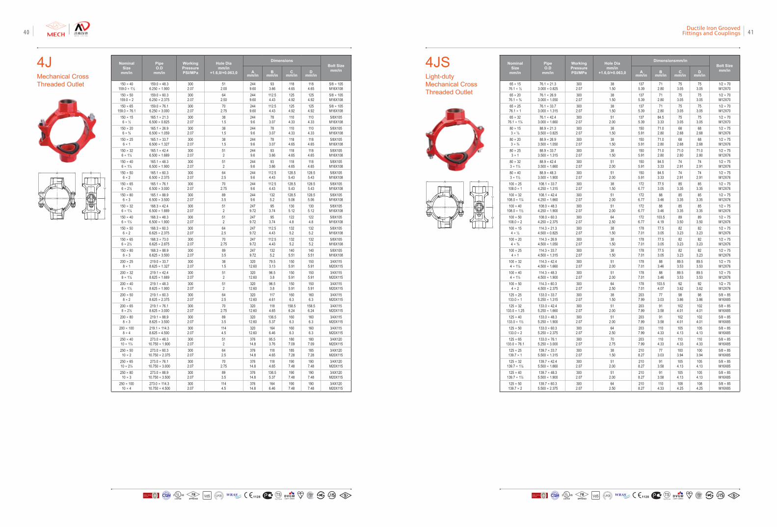
4JMechanical Cross Threaded Outlet
NominalSize
mm/in
PipeO.D
mm/in
Working PressurePSI/MPa
Hole Diamm/in
+1.6,0/+0.063,0
DimensionsBolt Size
mm/inAmm/in
Bmm/in
Cmm/in
Dmm/in
150×40159.0×1½
159.0×48.36.250×1.900
3002.07
512.00
2449.60
933.66
1184.65
1184.65
5/8×105M16X108
150×50159.0×2
159.0×60.36.250×2.375
3002.07
642.50
2449.60
112.54.43
1254.92
1254.92
5/8×105M16X108
150×65159.0×76.1
159.0×76.16.250×3.000
3002.07
702.75
2449.60
112.54.43
1254.92
1254.92
5/8×105M16X108
150×156×½
165.1×21.36.500×0.825
3002.07
381.5
2449.6
783.07
1104.33
1104.33
5/8X105M16X108
150×206×¾
165.1×26.96.500×1.059
3002.07
381.5
2449.6
783.07
1104.33
1104.33
5/8X105M16X108
150×256×1
165.1×33.76.500×1.327
3002.07
381.5
2449.6
783.07
1184.65
1184.65
5/8X105M16X108
150×326×1¼
165.1×42.46.500×1.669
3002.07
512
2449.6
933.66
1184.65
1184.65
5/8X105M16X108
150×406×1½
165.1×48.36.500×1.900
3002.07
512
2449.6
933.66
1184.65
1184.65
5/8X105M16X108
150×506×2
165.1×60.36.500×2.375
3002.07
642.5
2449.6
112.54.43
128.55.43
128.55.43
5/8X105M16X108
150×656×2½
165.1×76.16.500×3.000
3002.07
702.75
2449.6
112.54.43
128.55.43
128.55.43
5/8X105M16X108
150×806×3
165.1×88.96.500×3.500
3002.07
893.5
2449.6
1325.2
128.55.06
128.55.06
5/8X105M16X108
150×326×1¼
168.3×42.46.500×1.669
3002.07
512
2479.72
953.74
1305.12
1305.12
5/8X105M16X108
150×406×1½
168.3×48.36.500×1.900
3002.07
512
2479.72
953.74
1224.8
1224.8
5/8X105M16X108
150×506×2
168.3×60.36.625×2.375
3002.07
642.5
2479.72
112.54.43
1325.2
1325.2
5/8X105M16X108
150×656×2½
168.3×73.06.625×2.875
3002.07
702.75
2479.72
112.54.43
1325.2
1325.2
5/8X105M16X108
150×806×3
168.3×88.96.625×3.500
3002.07
893.5
2479.72
1325.2
1405.51
1405.51
5/8X105M16X108
200×258×1
219.0×33.78.625×1.327
3002.07
381.5
32012.60
79.53.13
1505.91
1505.91
3/4X115M20X115
200×328×1¼
219.1×42.48.625×1.669
3002.07
512
32012.60
96.53.8
1505.91
1505.91
3/4X115M20X115
200×408×1½
219.1×48.38.625×1.900
3002.07
512
32012.60
96.53.8
1505.91
1505.91
3/4X115M20X115
200×508×2
219.1×60.38.625×2.375
3002.07
642.5
32012.60
1174.61
1606.3
1606.3
3/4X115M20X115
200×658×2½
219.1×76.18.625×3.000
3002.07
702.75
32012.60
1184.65
158.56.24
158.56.24
3/4X115M20X115
200×808×3
219.1×88.98.625×3.500
3002.07
893.5
32012.60
136.55.37
1606.3
1606.3
3/4X115M20X115
200×1008×4
219.1×114.38.625×4.500
3002.07
1144.5
32012.60
1646.46
1606.3
1606.3
3/4X115M20X115
250×4010×1½
273.0×48.310.750×1.900
3002.07
512
37614.8
95.53.76
1807.09
1807.09
3/4X120M20X115
250×5010×2
273.0×60.310.750×2.375
3002.07
642.5
37614.8
1184.65
1857.28
1857.28
3/4X120M20X115
250×6510×2½
273.0×76.110.750×3.000
3002.07
702.75
37614.8
1184.65
1907.48
1907.48
3/4X120M20X115
250×8010×3
273.0×88.910.750×3.500
3002.07
893.5
37614.8
136.55.37
1907.48
1907.48
3/4X120M20X115
250×10010×4
273.0×114.310.750×4.500
3002.07
1144.5
37614.8
1646.46
1907.48
1907.48
3/4X120M20X115
4JSLight-duty Mechanical Cross Threaded Outlet
NominalSize
mm/in
PipeO.D
mm/in
Working PressurePSI/MPa
Hole Diamm/in
+1.6,0/+0.063,0
Dimensionsmm/inBolt Size
mm/inAmm/in
Bmm/in
Cmm/in
Dmm/in
65×1576.1×½
76.1×21.33.000×0.825
3002.07
381.50
1375.39
712.80
753.05
753.05
1/2×70M12X70
65×2076.1×¾
76.1×26.93.000×1.050
3002.07
381.50
1375.39
712.80
753.05
753.05
1/2×70M12X70
65×2576.1×1
76.1×33.73.000×1.315
3002.07
381.50
1375.39
712.80
753.05
753.05
1/2×70M12X70
65×3276.1×1¼
76.1×42.43.000×1.660
3002.07
512.00
1375.39
84.53.33
753.05
753.05
1/2×70M12X70
80×153×½
88.9×21.33.500×0.825
3002.07
381.50
1505.91
71.02.80
682.68
682.68
1/2×75M12X76
80×203×¾
88.9×26.93.500×1.050
3002.07
381.50
1505.91
71.02.80
682.68
682.68
1/2×75M12X76
80×253×1
88.9×33.73.500×1.315
3002.07
381.50
1505.91
71.02.80
71.02.80
71.02.80
1/2×75M12X76
80×323×1¼
88.9×42.43.500×1.660
3002.07
512.00
1505.91
84.53.33
742.91
742.91
1/2×75M12X76
80×403×1½
88.9×48.33.500×1.900
3002.07
512.00
1505.91
84.53.33
742.91
742.91
1/2×75M12X76
100×25108.0×1
108.1×33.74.250×1.315
3002.07
381.50
1726.77
77.53.05
853.35
853.35
1/2×75M12X76
100×32108.0×1¼
108.1×42.44.250×1.660
3002.07
512.00
1726.77
883.46
853.35
853.35
1/2×75M12X76
100×40108.0×1½
108.0×48.34.250×1.900
3002.07
512.00
1726.77
883.46
853.35
853.35
1/2×75M12X76
100×50108.0×2
108.0×60.34.250×2.375
3002.07
642.50
1726.77
103.54.19
893.50
893.50
1/2×75M12X76
100×154×½
114.3×21.34.500×0.825
3002.07
381.50
1787.01
77.53.05
823.23
823.23
1/2×75M12X76
100×204×¾
114.3×26.94.500×1.050
3002.07
381.50
1787.01
77.53.05
823.23
823.23
1/2×75M12X76
100×254×1
114.3×33.74.500×1.315
3002.07
381.50
1787.01
77.53.05
823.23
823.23
1/2×75M12X76
100×324×1¼
114.3×42.44.500×1.660
3002.07
512.00
1787.01
883.46
89.53.53
89.53.53
1/2×75M12X76
100×404×1½
114.3×48.34.500×1.900
3002.07
512.00
1787.01
883.46
89.53.53
89.53.53
1/2×75M12X76
100×504×2
114.3×60.34.500×2.375
3002.07
642.50
1787.01
103.54.07
923.62
923.62
1/2×75M12X76
125×25133.0×1
133.0×33.75.250×1.315
3002.07
381.50
2037.99
773.03
983.86
983.86
5/8×85M16X85
125×32133.0×1.25
133.0×42.45.250×1.660
3002.07
512.00
2037.99
913.58
1024.01
1024.01
5/8×85M16X85
125×40133.0×1½
133.0×48.35.250×1.900
3002.07
512.00
2037.99
913.58
1024.01
1024.01
5/8×85M16X85
125×50133.0×2
133.0×60.35.250×2.375
3002.07
642.50
2037.99
1104.33
1054.13
1054.13
5/8×85M16X85
125×65133.0×76.1
133.0×76.15.250×3.000
3002.07
702.75
2037.99
1104.33
1104.33
1104.33
5/8×85M16X85
125×25139.7×1
139.7×33.75.500×1.315
3002.07
381.50
2108.27
773.03
1003.94
1003.94
5/8×85M16X85
125×32139.7×1¼
139.7×42.45.500×1.660
3002.07
512.00
2108.27
913.58
1054.13
1054.13
5/8×85M16X85
125×40139.7×1½
139.7×48.35.500×1.900
3002.07
512.00
2108.27
913.58
1054.13
1054.13
5/8×85M16X85
125×50139.7×2
139.7×60.35.500×2.375
3002.07
642.50
2108.27
1104.33
1084.25
1084.25
5/8×85M16X85
VdS 1128 T STS2710Y44
WRASA P P R O V E D
P R O D U C TFM
APPROVED LOSS P
REVE
NTION CERTIFICATIO
N BO
ARD
CERTIF ICATIO
N
方
圆认证
BUREAU VERITASVdS 1128 T STS2710Y44
WRASA P P R O V E D
P R O D U C TFM
APPROVED LOSS P
REVE
NTION CERTIFICATIO
N BO
ARD
CERTIF ICATIO
N
方
圆认证
BUREAU VERITAS
Ductile Iron Grooved Fittings and Couplings 4140
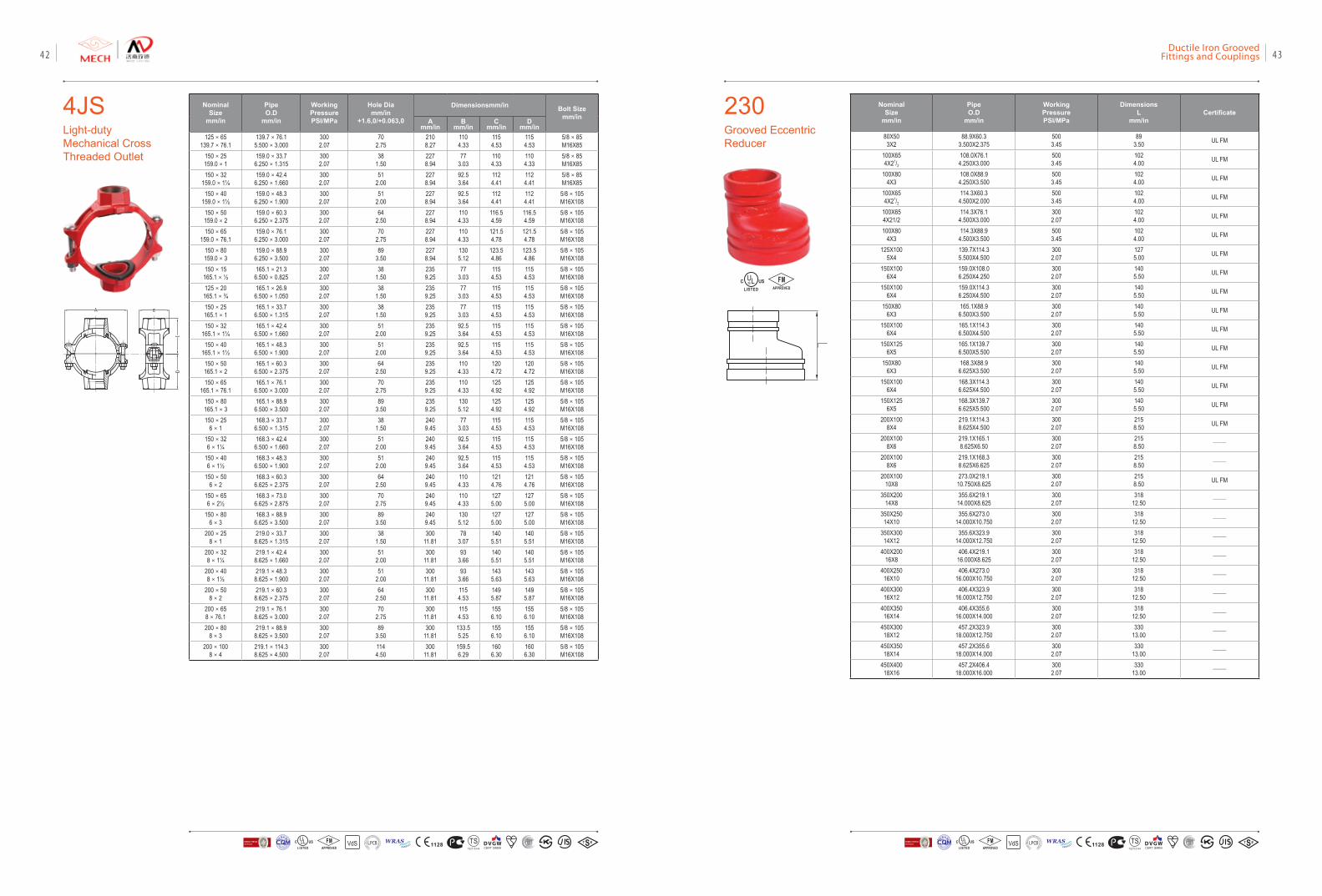
4JSLight-duty Mechanical Cross Threaded Outlet
NominalSize
mm/in
PipeO.D
mm/in
Working PressurePSI/MPa
Hole Diamm/in
+1.6,0/+0.063,0
Dimensionsmm/in Bolt Sizemm/inA
mm/inB
mm/inC
mm/inD
mm/in125×65
139.7×76.1139.7×76.15.500×3.000
3002.07
702.75
2108.27
1104.33
1154.53
1154.53
5/8×85M16X85
150×25159.0×1
159.0×33.76.250×1.315
3002.07
381.50
2278.94
773.03
1104.33
1104.33
5/8×85M16X85
150×32159.0×1¼
159.0×42.46.250×1.660
3002.07
512.00
2278.94
92.53.64
1124.41
1124.41
5/8×85M16X85
150×40159.0×1½
159.0×48.36.250×1.900
3002.07
512.00
2278.94
92.53.64
1124.41
1124.41
5/8×105M16X108
150×50159.0×2
159.0×60.36.250×2.375
3002.07
642.50
2278.94
1104.33
116.54.59
116.54.59
5/8×105M16X108
150×65159.0×76.1
159.0×76.16.250×3.000
3002.07
702.75
2278.94
1104.33
121.54.78
121.54.78
5/8×105M16X108
150×80159.0×3
159.0×88.96.250×3.500
3002.07
893.50
2278.94
1305.12
123.54.86
123.54.86
5/8×105M16X108
150×15165.1×½
165.1×21.36.500×0.825
3002.07
381.50
2359.25
773.03
1154.53
1154.53
5/8×105M16X108
125×20165.1×¾
165.1×26.96.500×1.050
3002.07
381.50
2359.25
773.03
1154.53
1154.53
5/8×105M16X108
150×25165.1×1
165.1×33.76.500×1.315
3002.07
381.50
2359.25
773.03
1154.53
1154.53
5/8×105M16X108
150×32165.1×1¼
165.1×42.46.500×1.660
3002.07
512.00
2359.25
92.53.64
1154.53
1154.53
5/8×105M16X108
150×40165.1×1½
165.1×48.36.500×1.900
3002.07
512.00
2359.25
92.53.64
1154.53
1154.53
5/8×105M16X108
150×50165.1×2
165.1×60.36.500×2.375
3002.07
642.50
2359.25
1104.33
1204.72
1204.72
5/8×105M16X108
150×65165.1×76.1
165.1×76.16.500×3.000
3002.07
702.75
2359.25
1104.33
1254.92
1254.92
5/8×105M16X108
150×80165.1×3
165.1×88.96.500×3.500
3002.07
893.50
2359.25
1305.12
1254.92
1254.92
5/8×105M16X108
150×256×1
168.3×33.76.500×1.315
3002.07
381.50
2409.45
773.03
1154.53
1154.53
5/8×105M16X108
150×326×1¼
168.3×42.46.500×1.660
3002.07
512.00
2409.45
92.53.64
1154.53
1154.53
5/8×105M16X108
150×406×1½
168.3×48.36.500×1.900
3002.07
512.00
2409.45
92.53.64
1154.53
1154.53
5/8×105M16X108
150×506×2
168.3×60.36.625×2.375
3002.07
642.50
2409.45
1104.33
1214.76
1214.76
5/8×105M16X108
150×656×2½
168.3×73.06.625×2.875
3002.07
702.75
2409.45
1104.33
1275.00
1275.00
5/8×105M16X108
150×806×3
168.3×88.96.625×3.500
3002.07
893.50
2409.45
1305.12
1275.00
1275.00
5/8×105M16X108
200×258×1
219.0×33.78.625×1.315
3002.07
381.50
30011.81
783.07
1405.51
1405.51
5/8×105M16X108
200×328×1¼
219.1×42.48.625×1.660
3002.07
512.00
30011.81
933.66
1405.51
1405.51
5/8×105M16X108
200×408×1½
219.1×48.38.625×1.900
3002.07
512.00
30011.81
933.66
1435.63
1435.63
5/8×105M16X108
200×508×2
219.1×60.38.625×2.375
3002.07
642.50
30011.81
1154.53
1495.87
1495.87
5/8×105M16X108
200×658×76.1
219.1×76.18.625×3.000
3002.07
702.75
30011.81
1154.53
1556.10
1556.10
5/8×105M16X108
200×808×3
219.1×88.98.625×3.500
3002.07
893.50
30011.81
133.55.25
1556.10
1556.10
5/8×105M16X108
200×1008×4
219.1×114.38.625×4.500
3002.07
1144.50
30011.81
159.56.29
1606.30
1606.30
5/8×105M16X108
230Grooved Eccentric Reducer
Nominal Size
mm/in
Pipe O.D
mm/in
Working PressurePSI/MPa
DimensionsL
mm/inCertificate
80X503X2
88.9X60.33.500X2.375
5003.45
893.50 UL FM
100X654X21/2
108.0X76.14.250X3.000
5003.45
1024.00 UL FM
100X804X3
108.0X88.94.250X3.500
5003.45
1024.00 UL FM
100X654X21/2
114.3X60.34.500X2.000
5003.45
1024.00 UL FM
100X654X21/2
114.3X76.14.500X3.000
3002.07
1024.00 UL FM
100X804X3
114.3X88.94.500X3.500
5003.45
1024.00 UL FM
125X1005X4
139.7X114.35.500X4.500
3002.07
1275.00 UL FM
150X1006X4
159.0X108.06.250X4.250
3002.07
1405.50 UL FM
150X1006X4
159.0X114.36.250X4.500
3002.07
1405.50 UL FM
150X806X3
165.1X88.96.500X3.500
3002.07
1405.50 UL FM
150X1006X4
165.1X114.36.500X4.500
3002.07
1405.50 UL FM
150X1256X5
165.1X139.76.500X5.500
3002.07
1405.50 UL FM
150X806X3
168.3X88.96.625X3.500
3002.07
1405.50 UL FM
150X1006X4
168.3X114.36.625X4.500
3002.07
1405.50 UL FM
150X1256X5
168.3X139.76.625X5.500
3002.07
1405.50 UL FM
200X1008X4
219.1X114.38.625X4.500
3002.07
2158.50 UL FM
200X1008X6
219.1X165.18.625X6.50
3002.07
2158.50 ——
200X1008X6
219.1X168.38.625X6.625
3002.07
2158.50 ——
200X10010X8
273.0X219.110.750X8.625
3002.07
2158.50 UL FM
350X20014X8
355.6X219.114.000X8.625
3002.07
31812.50 ——
350X25014X10
355.6X273.014.000X10.750
3002.07
31812.50 ——
350X30014X12
355.6X323.914.000X12.750
3002.07
31812.50 ——
400X20016X8
406.4X219.116.000X8.625
3002.07
31812.50 ——
400X25016X10
406.4X273.016.000X10.750
3002.07
31812.50 ——
400X30016X12
406.4X323.916.000X12.750
3002.07
31812.50 ——
400X35016X14
406.4X355.616.000X14.000
3002.07
31812.50 ——
450X30018X12
457.2X323.918.000X12.750
3002.07
33013.00 ——
450X35018X14
457.2X355.618.000X14.000
3002.07
33013.00 ——
450X40018X16
457.2X406.418.000X16.000
3002.07
33013.00 ——
FMAPPROVED
VdS 1128 T STS2710Y44
WRASA P P R O V E D
P R O D U C TFM
APPROVED LOSS P
REVE
NTION CERTIFICATIO
N BO
ARD
CERTIF ICATIO
N
方
圆认证
BUREAU VERITASVdS 1128 T STS2710Y44
WRASA P P R O V E D
P R O D U C TFM
APPROVED LOSS P
REVE
NTION CERTIFICATIO
N BO
ARD
CERTIF ICATIO
N
方
圆认证
BUREAU VERITAS
Ductile Iron Grooved Fittings and Couplings 4342
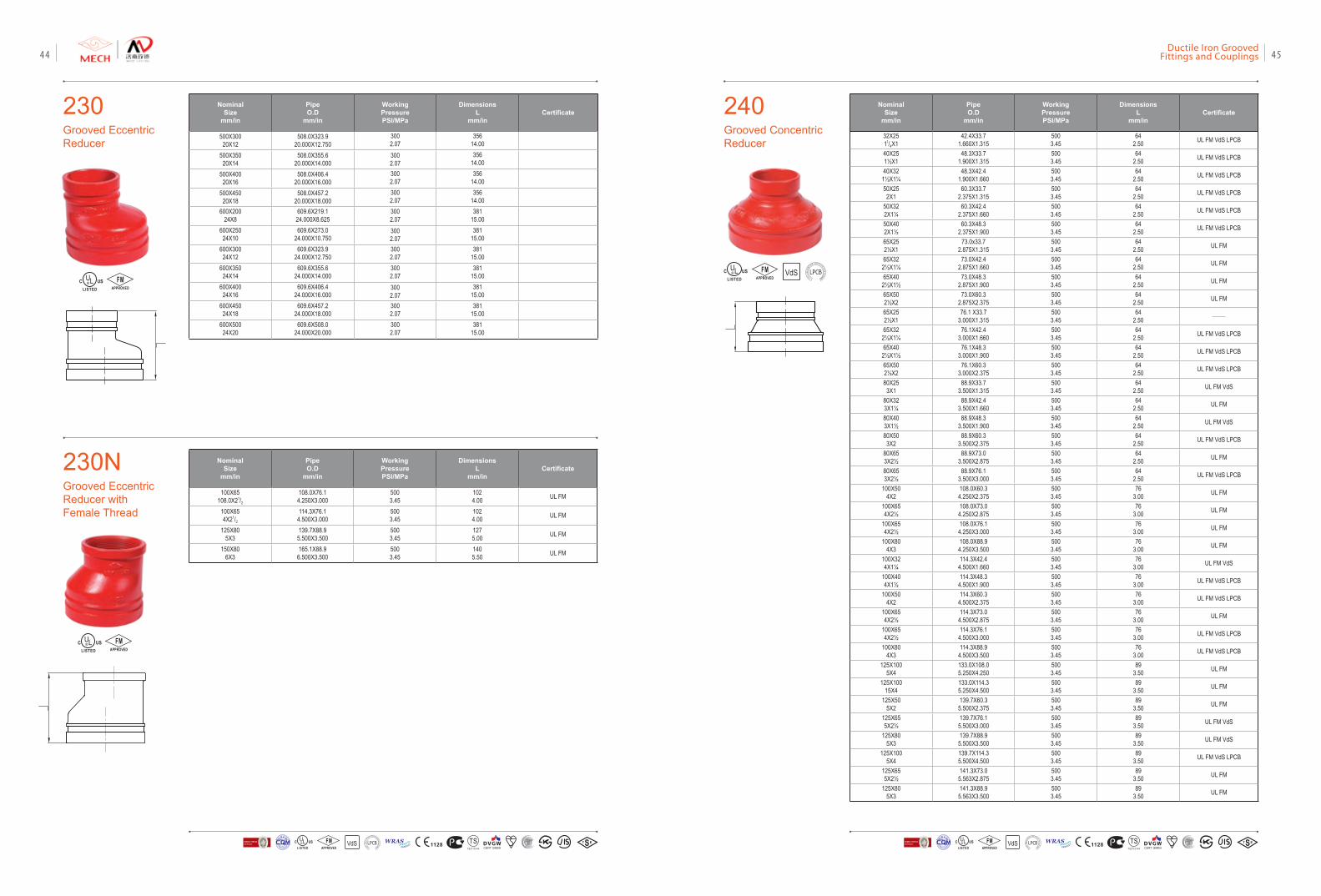
230Grooved Eccentric Reducer
230NGrooved Eccentric Reducer with Female Thread
Nominal Size
mm/in
Pipe O.D
mm/in
Working PressurePSI/MPa
DimensionsL
mm/inCertificate
500X30020X12
508.0X323.920.000X12.750
3002.07
35614.00
500X35020X14
508.0X355.620.000X14.000
3002.07
35614.00
500X40020X16
508.0X406.420.000X16.000
3002.07
35614.00
500X45020X18
508.0X457.220.000X18.000
3002.07
35614.00
600X20024X8
609.6X219.124.000X8.625
3002.07
38115.00
600X25024X10
609.6X273.024.000X10.750
3002.07
38115.00
600X30024X12
609.6X323.924.000X12.750
3002.07
38115.00
600X35024X14
609.6X355.624.000X14.000
3002.07
38115.00
600X40024X16
609.6X406.424.000X16.000
3002.07
38115.00
600X45024X18
609.6X457.224.000X18.000
3002.07
38115.00
600X50024X20
609.6X508.024.000X20.000
3002.07
38115.00
Nominal Size
mm/in
Pipe O.D
mm/in
Working PressurePSI/MPa
DimensionsL
mm/inCertificate
100X65108.0X21/2
108.0X76.14.250X3.000
5003.45
1024.00 UL FM
100X654X21/2
114.3X76.14.500X3.000
5003.45
1024.00 UL FM
125X805X3
139.7X88.95.500X3.500
5003.45
1275.00 UL FM
150X806X3
165.1X88.96.500X3.500
5003.45
1405.50 UL FM
FMAPPROVED
FMAPPROVED
240Grooved ConcentricReducer
Nominal Size
mm/in
Pipe O.D
mm/in
Working PressurePSI/MPa
DimensionsL
mm/inCertificate
32X2511/4X1
42.4X33.71.660X1.315
5003.45
642.50 UL FM VdS LPCB
40X251½X1
48.3X33.71.900X1.315
5003.45
642.50 UL FM VdS LPCB
40X321½X1¼
48.3X42.41.900X1.660
5003.45
642.50 UL FM VdS LPCB
50X252X1
60.3X33.72.375X1.315
5003.45
642.50 UL FM VdS LPCB
50X322X1¼
60.3X42.42.375X1.660
5003.45
642.50 UL FM VdS LPCB
50X402X1½
60.3X48.32.375X1.900
5003.45
642.50 UL FM VdS LPCB
65X252½X1
73.0x33.72.875X1.315
5003.45
642.50 UL FM
65X322½X1¼
73.0X42.42.875X1.660
5003.45
642.50 UL FM
65X402½X1½
73.0X48.32.875X1.900
5003.45
642.50 UL FM
65X502½X2
73.0X60.32.875X2.375
5003.45
642.50 UL FM
65X252½X1
76.1 X33.73.000X1.315
5003.45
642.50 ——
65X322½X1¼
76.1X42.43.000X1.660
5003.45
642.50 UL FM VdS LPCB
65X402½X1½
76.1X48.33.000X1.900
5003.45
642.50 UL FM VdS LPCB
65X502½X2
76.1X60.33.000X2.375
5003.45
642.50 UL FM VdS LPCB
80X253X1
88.9X33.73.500X1.315
5003.45
642.50 UL FM VdS
80X323X1¼
88.9X42.43.500X1.660
5003.45
642.50 UL FM
80X403X1½
88.9X48.33.500X1.900
5003.45
642.50 UL FM VdS
80X503X2
88.9X60.33.500X2.375
5003.45
642.50 UL FM VdS LPCB
80X653X2½
88.9X73.03.500X2.875
5003.45
642.50 UL FM
80X653X2½
88.9X76.13.500X3.000
5003.45
642.50 UL FM VdS LPCB
100X504X2
108.0X60.34.250X2.375
5003.45
763.00 UL FM
100X654X2½
108.0X73.04.250X2.875
5003.45
763.00 UL FM
100X654X2½
108.0X76.14.250X3.000
5003.45
763.00 UL FM
100X804X3
108.0X88.94.250X3.500
5003.45
763.00 UL FM
100X324X1¼
114.3X42.44.500X1.660
5003.45
763.00 UL FM VdS
100X404X1½
114.3X48.34.500X1.900
5003.45
763.00 UL FM VdS LPCB
100X504X2
114.3X60.34.500X2.375
5003.45
763.00 UL FM VdS LPCB
100X654X2½
114.3X73.04.500X2.875
5003.45
763.00 UL FM
100X654X2½
114.3X76.14.500X3.000
5003.45
763.00 UL FM VdS LPCB
100X804X3
114.3X88.94.500X3.500
5003.45
763.00 UL FM VdS LPCB
125X1005X4
133.0X108.05.250X4.250
5003.45
893.50 UL FM
125X10015X4
133.0X114.35.250X4.500
5003.45
893.50 UL FM
125X505X2
139.7X60.35.500X2.375
5003.45
893.50 UL FM
125X655X2½
139.7X76.15.500X3.000
5003.45
893.50 UL FM VdS
125X805X3
139.7X88.95.500X3.500
5003.45
893.50 UL FM VdS
125X1005X4
139.7X114.35.500X4.500
5003.45
893.50 UL FM VdS LPCB
125X655X2½
141.3X73.05.563X2.875
5003.45
893.50 UL FM
125X805X3
141.3X88.95.563X3.500
5003.45
893.50 UL FM
VdSFMAPPROVED LOSS
PRE
VENTIO
N CERTIFICATION
BOARD
VdS 1128 T STS2710Y44
WRASA P P R O V E D
P R O D U C TFM
APPROVED LOSS P
REVE
NTION CERTIFICATIO
N BO
ARD
CERTIF ICATIO
N
方
圆认证
BUREAU VERITASVdS 1128 T STS2710Y44
WRASA P P R O V E D
P R O D U C TFM
APPROVED LOSS P
REVE
NTION CERTIFICATIO
N BO
ARD
CERTIF ICATIO
N
方
圆认证
BUREAU VERITAS
Ductile Iron Grooved Fittings and Couplings 4544
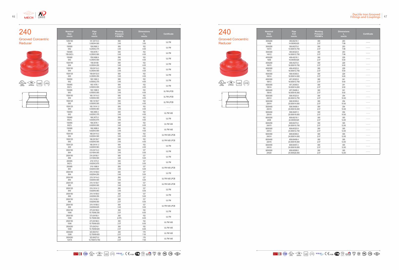
240Grooved ConcentricReducer
Nominal Size
mm/in
Pipe O.D
mm/in
Working PressurePSI/MPa
DimensionsL
mm/inCertificate
125X1005X4
141.3X114.35.563X4.500
5003.45
893.50 UL FM
150X506X2
159.0X60.36.250X2.375
5003.45
1024.00 UL FM
150X65159.0X2½
159.0X76.16.250X3.000
5003.45
1024.00 UL FM
150X806X3
159.0X88.96.250X3.500
5003.45
1024.00 UL FM
150X1006X4
159.0X1086.250X4.250
5003.45
1024.00 UL FM
150X1006X4
159.0X114.36.250X4.500
5003.45
1024.00 UL FM
150X1256X5
159.0X133.06.250X5.250
5003.45
1024.00 UL FM
150X506X2
165.1X60.36.500X2.375
5003.45
1024.00 UL FM
150X656X2½
165.1X76.16.500X3.000
5003.45
1024.00 UL FM
150X806X3
165.1X88.96.500X3.500
5003.45
1024.00 UL FM LPCB
150X1006X4
165.1X114.36.500X4.500
5003.45
1024.00 UL FM LPCB
150X1256X5
165.1X139.76.500X5.500
5003.45
1024.00 UL FM LPCB
150X1256X5
165.1X141.36.500X5.563
5003.45
1024.00 ——
150X506X2
168.3X60.36.625X2.375
5003.45
1024.00 UL FM VdS
150X656X2½
168.3X73.06.625X2.875
5003.45
1024.00 UL FM
150X656X2½
168.3X76.16.625X3.000
5003.45
1024.00 UL FM VdS
150X806X3
168.3X88.96.625X3.500
5003.45
1024.00 UL FM VdS
150X1006X4
168.3X114.36.625X4.500
5003.45
1024.00 UL FM VdS LPCB
150X1256X5
168.3X139.76.625X5.500
5003.45
1024.00 UL FM VdS LPCB
150X1256X5
168.3X141.36.625X5.563
5003.45
1024.00 UL FM
200X1008X4
216.3X114.38.516X4.500
5003.45
1275.00 UL FM
200X1508X6
216.3X165.18.516X6.500
5003.45
1275.00 UL FM
200X658X2½
219.1X73.08.625X2.875
5003.45
1275.00 UL FM
200X808X3
219.1X88.98.625X3.500
5003.45
1275.00 UL FM VdS LPCB
200X1008X4
219.1X108.08.625X4.250
5003.45
1275.00 UL FM
200X1008X4
219.1X114.38.625X4.500
5003.45
1275.00 UL FM VdS LPCB
200X1258X5
219.1X139.78.625X5.500
5003.45
1275.00 UL FM VdS LPCB
200X1258X5
219.1X141.38.625X5.563
5003.45
1275.00 UL FM
200X1508X6
219.1X159.08.625X6.250
3002.07
1275.00 UL FM
200X1508X6
219.1X165.18.625X6.500
3002.07
1275.00 UL FM
200X1508X6
219.1X168.38.625X6.625
5003.45
1275.00 UL FM VdS LPCB
250X15010X6
273.0X159.010.750X6.250
3002.07
1526.00 UL FM
250X15010X6
273.0X165.110.750X6.500
3002.075
1526.00 UL FM
250X15010X6
273.0X168.310.750X6.625
3002.07
1526.00 UL FM VdS
250X20010X8
273.0X219.110.750X8.625
3002.07
1526.00 UL FM VdS
300X20012X8
323.9X219.112.750X8.625
3002.07
1787.00 UL FM VdS
300X25012X10
323.9X273.012.750X10.750
3002.07
1787.00 UL FM VdS
VdSFMAPPROVED LOSS
PRE
VENTIO
N CERTIFICATION
BOARD
240Grooved ConcentricReducer
Nominal Size
mm/in
Pipe O.D
mm/in
Working PressurePSI/MPa
DimensionsL
mm/inCertificate
350X20014X8
355.6X219.114.000X8.625
3002.07
2037.99 ——
350X25014X10
355.6X273.014.000X10.750
3002.07
2037.99 ——
350X30014X12
355.6X323.914.000X12.750
3002.07
2037.99 ——
400X20016X8
406.4X219.116.000X8.625
3002.07
2299.00 ——
400X25016X10
406.4X273.016.000X10.750
3002.07
2299.00 ——
400X30016X12
406.4X323.916.000X12.750
3002.07
2299.00 ——
400X35016X14
406.4X355.616.000X14.000
3002.07
2299.00 ——
450X30018X12
457.2X323.918.000X12.750
3002.07
2419.50 ——
450X35018X14
457.2X355.618.000X14.000
3002.07
2419.50 ——
450X40018X16
457.2X406.418.000X16.000
3002.07
2419.50 ——
500X30020X12
508.0X323.920.000X12.750
3002.07
25410.00 ——
500X35020X14
508.0X355.620.000X14.000
3002.07
25410.00 ——
500X40020X16
508.0X406.420.000X16.000
3002.07
25410.00 ——
500X45020X18
508.0X457.220.000X18.000
3002.07
25410.00 ——
600X20024X8
609.6X219.124.000X8.625
3002.07
30512.00 ——
600X25024X10
609.6X273.024.000X10.750
3002.07
30512.00 ——
600X30024X12
609.6X323.924.000X12.750
3002.07
30512.00 ——
600X35024X14
609.6X355.624.000X14.000
3002.07
30512.00 ——
600X40024X16
609.6X406.424.000X16.000
3002.07
30512.00 ——
600X45024X18
609.6X457.224.000X18.000
3002.07
30512.00 ——
600X50024X20
609.6X508.024.000X20.000
3002.07
30512.00 ——
VdSFMAPPROVED LOSS
PRE
VENTIO
N CERTIFICATION
BOARD
VdS 1128 T STS2710Y44
WRASA P P R O V E D
P R O D U C TFM
APPROVED LOSS P
REVE
NTION CERTIFICATIO
N BO
ARD
CERTIF ICATIO
N
方
圆认证
BUREAU VERITASVdS 1128 T STS2710Y44
WRASA P P R O V E D
P R O D U C TFM
APPROVED LOSS P
REVE
NTION CERTIFICATIO
N BO
ARD
CERTIF ICATIO
N
方
圆认证
BUREAU VERITAS
Ductile Iron Grooved Fittings and Couplings 4746
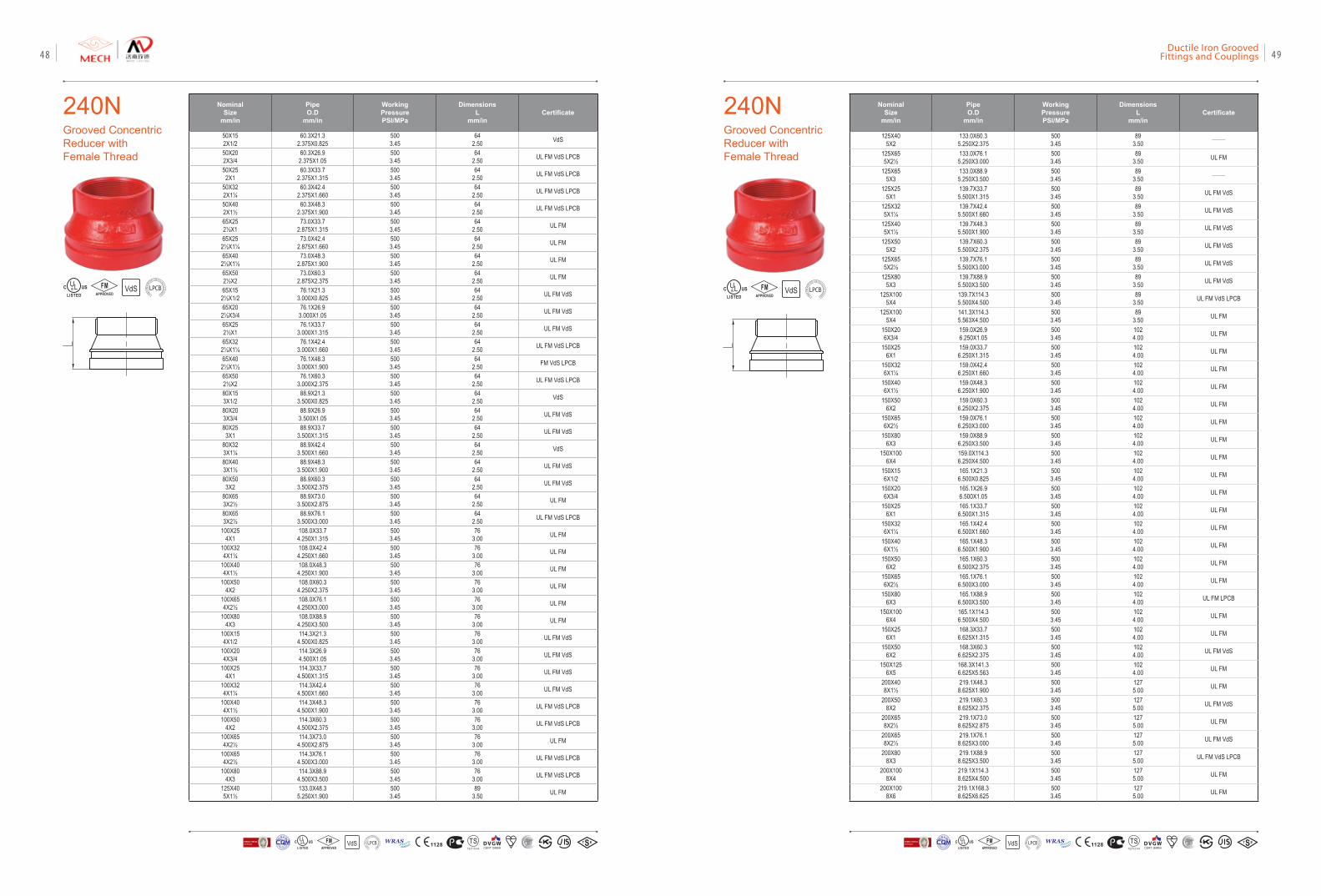
240NGrooved ConcentricReducer with Female Thread
Nominal Size
mm/in
Pipe O.D
mm/in
Working PressurePSI/MPa
DimensionsL
mm/inCertificate
50X152X1/2
60.3X21.32.375X0.825
5003.45
642.50 VdS
50X202X3/4
60.3X26.92.375X1.05
5003.45
642.50 UL FM VdS LPCB
50X252X1
60.3X33.72.375X1.315
5003.45
642.50 UL FM VdS LPCB
50X322X1¼
60.3X42.42.375X1.660
5003.45
642.50 UL FM VdS LPCB
50X402X1½
60.3X48.32.375X1.900
5003.45
642.50 UL FM VdS LPCB
65X252½X1
73.0X33.72.875X1.315
5003.45
642.50 UL FM
65X252½X1¼
73.0X42.42.875X1.660
5003.45
642.50 UL FM
65X402½X1½
73.0X48.32.875X1.900
5003.45
642.50 UL FM
65X502½X2
73.0X60.32.875X2.375
5003.45
642.50 UL FM
65X152½X1/2
76.1X21.33.000X0.825
5003.45
642.50 UL FM VdS
65X202½X3/4
76.1X26.93.000X1.05
5003.45
642.50 UL FM VdS
65X252½X1
76.1X33.73.000X1.315
5003.45
642.50 UL FM VdS
65X322½X1¼
76.1X42.43.000X1.660
5003.45
642.50 UL FM VdS LPCB
65X402½X1½
76.1X48.33.000X1.900
5003.45
642.50 FM VdS LPCB
65X502½X2
76.1X60.33.000X2.375
5003.45
642.50 UL FM VdS LPCB
80X153X1/2
88.9X21.33.500X0.825
5003.45
642.50 VdS
80X203X3/4
88.9X26.93.500X1.05
5003.45
642.50 UL FM VdS
80X253X1
88.9X33.73.500X1.315
5003.45
642.50 UL FM VdS
80X323X1¼
88.9X42.43.500X1.660
5003.45
642.50 VdS
80X403X1½
88.9X48.33.500X1.900
5003.45
642.50 UL FM VdS
80X503X2
88.9X60.33.500X2.375
5003.45
642.50 UL FM VdS
80X653X2½
88.9X73.03.500X2.875
5003.45
642.50 UL FM
80X653X2½
88.9X76.13.500X3.000
5003.45
642.50 UL FM VdS LPCB
100X254X1
108.0X33.74.250X1.315
5003.45
763.00 UL FM
100X324X1¼
108.0X42.44.250X1.660
5003.45
763.00 UL FM
100X404X1½
108.0X48.34.250X1.900
5003.45
763.00 UL FM
100X504X2
108.0X60.34.250X2.375
5003.45
763.00 UL FM
100X654X2½
108.0X76.14.250X3.000
5003.45
763.00 UL FM
100X804X3
108.0X88.94.250X3.500
5003.45
763.00 UL FM
100X154X1/2
114.3X21.34.500X0.825
5003.45
763.00 UL FM VdS
100X204X3/4
114.3X26.94.500X1.05
5003.45
763.00 UL FM VdS
100X254X1
114.3X33.74.500X1.315
5003.45
763.00 UL FM VdS
100X324X1¼
114.3X42.44.500X1.660
5003.45
763.00 UL FM VdS
100X404X1½
114.3X48.34.500X1.900
5003.45
763.00 UL FM VdS LPCB
100X504X2
114.3X60.34.500X2.375
5003.45
763.00 UL FM VdS LPCB
100X654X2½
114.3X73.04.500X2.875
5003.45
763.00 UL FM
100X654X2½
114.3X76.14.500X3.000
5003.45
763.00 UL FM VdS LPCB
100X804X3
114.3X88.94.500X3.500
5003.45
763.00 UL FM VdS LPCB
125X405X1½
133.0X48.35.250X1.900
5003.45
893.50 UL FM
VdSFMAPPROVED LOSS
PRE
VENTIO
N CERTIFICATION
BOARD
240NGrooved ConcentricReducer with Female Thread
Nominal Size
mm/in
Pipe O.D
mm/in
Working PressurePSI/MPa
DimensionsL
mm/inCertificate
125X405X2
133.0X60.35.250X2.375
5003.45
893.50 ——
125X655X2½
133.0X76.15.250X3.000
5003.45
893.50 UL FM
125X655X3
133.0X88.95.250X3.500
5003.45
893.50 ——
125X255X1
139.7X33.75.500X1.315
5003.45
893.50 UL FM VdS
125X325X1¼
139.7X42.45.500X1.660
5003.45
893.50 UL FM VdS
125X405X1½
139.7X48.35.500X1.900
5003.45
893.50 UL FM VdS
125X505X2
139.7X60.35.500X2.375
5003.45
893.50 UL FM VdS
125X655X2½
139.7X76.15.500X3.000
5003.45
893.50 UL FM VdS
125X805X3
139.7X88.95.500X3.500
5003.45
893.50 UL FM VdS
125X1005X4
139.7X114.35.500X4.500
5003.45
893.50 UL FM VdS LPCB
125X1005X4
141.3X114.35.563X4.500
5003.45
893.50 UL FM
150X206X3/4
159.0X26.96.250X1.05
5003.45
1024.00 UL FM
150X256X1
159.0X33.76.250X1.315
5003.45
1024.00 UL FM
150X326X1¼
159.0X42.46.250X1.660
5003.45
1024.00 UL FM
150X406X1½
159.0X48.36.250X1.900
5003.45
1024.00 UL FM
150X506X2
159.0X60.36.250X2.375
5003.45
1024.00 UL FM
150X656X2½
159.0X76.16.250X3.000
5003.45
1024.00 UL FM
150X806X3
159.0X88.96.250X3.500
5003.45
1024.00 UL FM
150X1006X4
159.0X114.36.250X4.500
5003.45
1024.00 UL FM
150X156X1/2
165.1X21.36.500X0.825
5003.45
1024.00 UL FM
150X206X3/4
165.1X26.96.500X1.05
5003.45
1024.00 UL FM
150X256X1
165.1X33.76.500X1.315
5003.45
1024.00 UL FM
150X326X1¼
165.1X42.46.500X1.660
5003.45
1024.00 UL FM
150X406X1½
165.1X48.36.500X1.900
5003.45
1024.00 UL FM
150X506X2
165.1X60.36.500X2.375
5003.45
1024.00 UL FM
150X656X2½
165.1X76.16.500X3.000
5003.45
1024.00 UL FM
150X806X3
165.1X88.96.500X3.500
5003.45
1024.00 UL FM LPCB
150X1006X4
165.1X114.36.500X4.500
5003.45
1024.00 UL FM
150X256X1
168.3X33.76.625X1.315
5003.45
1024.00 UL FM
150X506X2
168.3X60.36.625X2.375
5003.45
1024.00 UL FM VdS
150X1256X5
168.3X141.36.625X5.563
5003.45
1024.00 UL FM
200X408X1½
219.1X48.38.625X1.900
5003.45
1275.00 UL FM
200X508X2
219.1X60.38.625X2.375
5003.45
1275.00 UL FM VdS
200X658X2½
219.1X73.08.625X2.875
5003.45
1275.00 UL FM
200X658X2½
219.1X76.18.625X3.000
5003.45
1275.00 UL FM VdS
200X808X3
219.1X88.98.625X3.500
5003.45
1275.00 UL FM VdS LPCB
200X1008X4
219.1X114.38.625X4.500
5003.45
1275.00 UL FM
200X1008X6
219.1X168.38.625X6.625
5003.45
1275.00 UL FM
VdSFMAPPROVED LOSS
PRE
VENTIO
N CERTIFICATION
BOARD
VdS 1128 T STS2710Y44
WRASA P P R O V E D
P R O D U C TFM
APPROVED LOSS P
REVE
NTION CERTIFICATIO
N BO
ARD
CERTIF ICATIO
N
方
圆认证
BUREAU VERITASVdS 1128 T STS2710Y44
WRASA P P R O V E D
P R O D U C TFM
APPROVED LOSS P
REVE
NTION CERTIFICATIO
N BO
ARD
CERTIF ICATIO
N
方
圆认证
BUREAU VERITAS
Ductile Iron Grooved Fittings and Couplings 4948
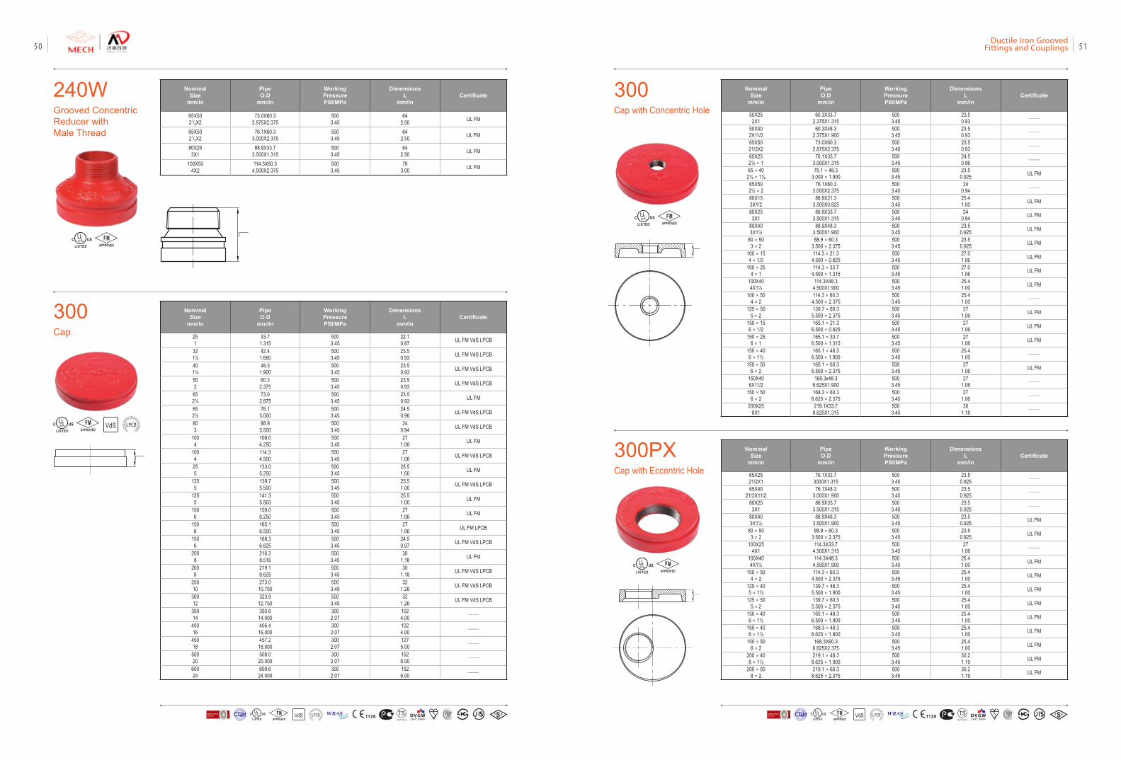
240WGrooved Concentric Reducer with Male Thread
300Cap
Nominal Size
mm/in
Pipe O.D
mm/in
Working PressurePSI/MPa
DimensionsL
mm/inCertificate
65X5021/2X2
73.0X60.32.875X2.375
5003.45
642.50 UL FM
65X5021/2X2
76.1X60.33.000X2.375
5003.45
642.50 UL FM
80X253X1
88.9X33.73.500X1.315
5003.45
642.50 UL FM
100X504X2
114.3X60.34.500X2.375
5003.45
763.00 UL FM
Nominal Size
mm/in
Pipe O.D
mm/in
Working PressurePSI/MPa
DimensionsL
mm/inCertificate
251
33.71.315
5003.45
22.10.87 UL FM VdS LPCB
321¼
42.41.660
5003.45
23.50.93 UL FM VdS LPCB
401½
48.31.900
5003.45
23.50.93 UL FM VdS LPCB
502
60.32.375
5003.45
23.50.93 UL FM VdS LPCB
652½
73.02.875
5003.45
23.50.93 UL FM
652½
76.13.000
5003.45
24.50.96 UL FM VdS LPCB
803
88.93.500
5003.45
240.94 UL FM VdS LPCB
1004
108.04.250
5003.45
271.06 UL FM
1004
114.34.500
5003.45
271.06 UL FM VdS LPCB
255
133.05.250
5003.45
25.51.00 UL FM
1255
139.75.500
5003.45
25.51.00 UL FM VdS LPCB
1255
141.35.563
5003.45
25.51.00 UL FM
1506
159.06.250
5003.45
271.06 UL FM
1506
165.16.500
5003.45
271.06 UL FM LPCB
1506
168.36.625
5003.45
24.50.97 UL FM VdS LPCB
2008
216.38.516
5003.45
301.18 UL FM
2008
219.18.625
5003.45
301.18 UL FM VdS LPCB
25010
273.010.750
5003.45
321.26 UL FM VdS LPCB
30012
323.912.750
5003.45
321.26 UL FM VdS LPCB
35014
355.614.000
3002.07
1024.00 ——
40016
406.416.000
3002.07
1024.00 ——
45018
457.218.000
3002.07
1275.00 ——
50020
508.020.000
3002.07
1526.00 ——
60024
609.624.000
3002.07
1526.00 ——
FMAPPROVED
VdSFMAPPROVED LOSS
PRE
VENTIO
N CERTIFICATION
BOARD
300Cap with Concentric Hole
Nominal Size
mm/in
Pipe O.D
mm/in
Working PressurePSI/MPa
DimensionsL
mm/inCertificate
50X252X1
60.3X33.72.375X1.315
5003.45
23.50.93 ——
50X402X11/2
60.3X48.32.375X1.900
5003.45
23.50.93 ——
65X5021/2X2
73.0X60.32.875X2.375
5003.45
23.50.93 ——
65X252½×1
76.1X33.73.000X1.315
5003.45
24.50.96 ——
65×402½×1½
76.1×48.33.000×1.900
5003.45
23.50.925 UL FM
65X502½×2
76.1X60.33.000X2.375
5003.45
240.94 ——
80X153X1/2
88.9X21.33.500X0.825
5003.45
25.41.00 UL FM
80X253X1
88.9X33.73.500X1.315
5003.45
240.94 UL FM
80X403X1½
88.9X48.33.500X1.900
5003.45
23.50.925 UL FM
80×503×2
88.9×60.33.500×2.375
5003.45
23.50.925 UL FM
100×154×1/2
114.3×21.34.500×0.825
5003.45
27.01.06 UL FM
100×254×1
114.3×33.74.500×1.315
5003.45
27.01.06 UL FM
100X404X1½
114.3X48.34.500X1.900
5003.45
25.41.00 UL FM
100×504×2
114.3×60.34.500×2.375
5003.45
25.41.00 ——
125×505×2
139.7×60.35.500×2.375
5003.45
271.06 UL FM
150×156×1/2
165.1×21.36.500×0.825
5003.45
271.06 UL FM
150×256×1
165.1×33.76.500×1.315
5003.45
271.06 UL FM
150×406×1½
165.1×48.36.500×1.900
5003.45
25.41.00 ——
150×506×2
165.1×60.36.500×2.375
5003.45
271.06 UL FM
150X406X11/2
168.3x48.36.625X1.900
5003.45
271.06 ——
150×506×2
168.3×60.36.625×2.375
5003.45
271.06 ——
200X258X1
219.1X33.78.625X1.315
5003.45
301.18 ——
300PXCap with Eccentric Hole
Nominal Size
mm/in
Pipe O.D
mm/in
Working PressurePSI/MPa
DimensionsL
mm/inCertificate
65X2521/2X1
76.1X33.73000X1.315
5003.45
23.50.925 ——
65X4021/2X11/2
76.1X48.33.000X1.900
5003.45
23.50.925 ——
80X253X1
88.9X33.73.500X1.315
5003.45
23.50.925 ——
80X403X1½
88.9X48.33.500X1.900
5003.45
23.50.925 UL FM
80×503×2
88.9×60.33.500×2.375
5003.45
23.50.925 UL FM
100X254X1
114.3X33.74.500X1.315
5003.45
271.06 ——
100X404X1½
114.3X48.34.500X1.900
5003.45
25.41.00 UL FM
100×504×2
114.3×60.34.500×2.375
5003.45
25.41.00 UL FM
125×405×1½
139.7×48.35.500×1.900
5003.45
25.41.00 UL FM
125×505×2
139.7×60.35.500×2.375
5003.45
25.41.00 UL FM
150×406×1½
165.1×48.36.500×1.900
5003.45
25.41.00 UL FM
150×406×1½
168.3×48.36.625×1.900
5003.45
25.41.00 UL FM
150×506×2
168.3X60.36.625X2.375
5003.45
25.41.00 UL FM
200×408×1½
219.1×48.38.625×1.900
5003.45
30.21.19 UL FM
200×508×2
219.1×60.38.625×2.375
5003.45
30.21.19 UL FM
FMAPPROVED
FMAPPROVED
VdS 1128 T STS2710Y44
WRASA P P R O V E D
P R O D U C TFM
APPROVED LOSS P
REVE
NTION CERTIFICATIO
N BO
ARD
CERTIF ICATIO
N
方
圆认证
BUREAU VERITASVdS 1128 T STS2710Y44
WRASA P P R O V E D
P R O D U C TFM
APPROVED LOSS P
REVE
NTION CERTIFICATIO
N BO
ARD
CERTIF ICATIO
N
方
圆认证
BUREAU VERITAS
Ductile Iron Grooved Fittings and Couplings 5150
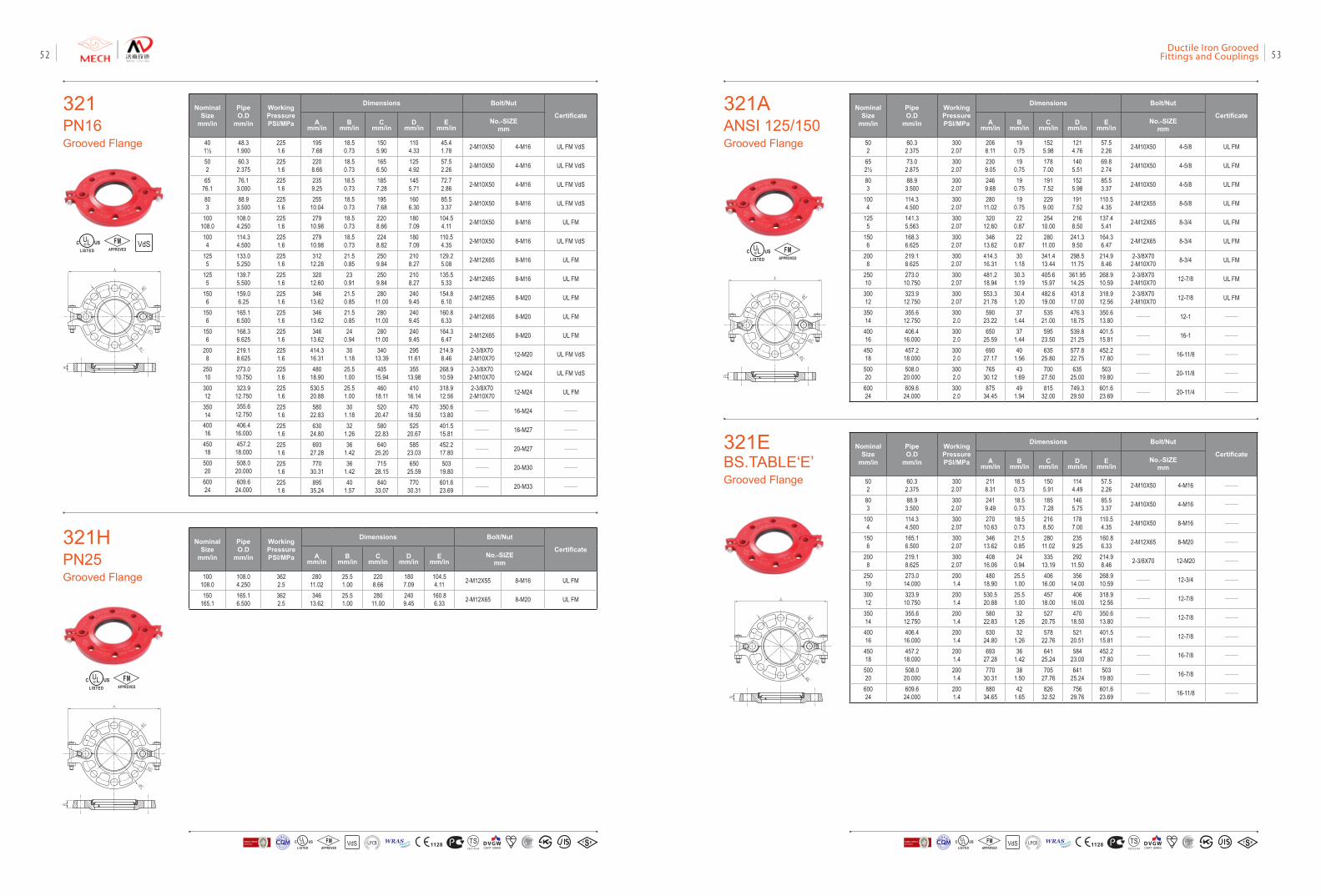
321PN16Grooved Flange
NominalSize
mm/in
PipeO.D
mm/in
Working PressurePSI/MPa
Dimensions Bolt/Nut
CertificateA
mm/inB
mm/inC
mm/inD
mm/inE
mm/inNo.-SIZE
mm
401½
48.31.900
2251.6
1957.68
18.50.73
1505.90
1104.33
45.41.78 2-M10X50 4-M16 UL FM VdS
502
60.32.375
2251.6
2208.66
18.50.73
1656.50
1254.92
57.52.26 2-M10X50 4-M16 UL FM VdS
6576.1
76.13.000
2251.6
2359.25
18.50.73
1857.28
1455.71
72.72.86 2-M10X50 4-M16 UL FM VdS
803
88.93.500
2251.6
25510.04
18.50.73
1957.68
1606.30
85.53.37 2-M10X50 8-M16 UL FM VdS
100108.0
108.04.250
2251.6
27910.98
18.50.73
2208.66
1807.09
104.54.11 2-M10X50 8-M16 UL FM
1004
114.34.500
2251.6
27910.98
18.50.73
2248.82
1807.09
110.54.35 2-M10X50 8-M16 UL FM VdS
1255
133.05.250
2251.6
31212.28
21.50.85
2509.84
2108.27
129.25.08 2-M12X65 8-M16 UL FM
1255
139.75.500
2251.6
32012.60
230.91
2509.84
2108.27
135.55.33 2-M12X65 8-M16 UL FM
1506
159.06.25
2251.6
34613.62
21.50.85
28011.00
2409.45
154.86.10 2-M12X65 8-M20 UL FM
1506
165.16.500
2251.6
34613.62
21.50.85
28011.00
2409.45
160.86.33 2-M12X65 8-M20 UL FM
1506
168.36.625
2251.6
34613.62
240.94
28011.00
2409.45
164.36.47 2-M12X65 8-M20 UL FM
2008
219.18.625
2251.6
414.316.31
301.18
34013.39
29511.61
214.98.46
2-3/8X702-M10X70 12-M20 UL FM VdS
25010
273.010.750
2251.6
48018.90
25.51.00
40515.94
35513.98
268.910.59
2-3/8X702-M10X70 12-M24 UL FM VdS
30012
323.912.750
2251.6
530.520.88
25.51.00
46018.11
41016.14
318.912.56
2-3/8X702-M10X70 12-M24 UL FM
35014
355.612.750
2251.6
58022.83
301.18
52020.47
47018.50
350.613.80 —— 16-M24 ——
40016
406.416.000
2251.6
63024.80
321.26
58022.83
52520.67
401.515.81 —— 16-M27 ——
45018
457.218.000
2251.6
69327.28
361.42
64025.20
58523.03
452.217.80 —— 20-M27 ——
50020
508.020.000
2251.6
77030.31
361.42
71528.15
65025.59
50319.80 —— 20-M30 ——
60024
609.624.000
2251.6
89535.24
401.57
84033.07
77030.31
601.623.69 —— 20-M33 ——
VdSFMAPPROVED
321AANSI 125/150Grooved Flange
NominalSize
mm/in
PipeO.D
mm/in
Working PressurePSI/MPa
Dimensions Bolt/Nut
CertificateA
mm/inB
mm/inC
mm/inD
mm/inE
mm/inNo.-SIZE
mm
502
60.32.375
3002.07
2068.11
190.75
1525.98
1214.76
57.52.26 2-M10X50 4-5/8 UL FM
652½
73.02.875
3002.07
2309.05
190.75
1787.00
1405.51
69.82.74 2-M10X50 4-5/8 UL FM
803
88.93.500
3002.07
2469.68
190.75
1917.52
1525.98
85.53.37 2-M10X50 4-5/8 UL FM
1004
114.34.500
3002.07
28011.02
190.75
2299.00
1917.52
110.54.35 2-M12X55 8-5/8 UL FM
1255
141.35.563
3002.07
32012.60
220.87
25410.00
2168.50
137.45.41 2-M12X65 8-3/4 UL FM
1506
168.36.625
3002.07
34613.62
220.87
28011.00
241.39.50
164.36.47 2-M12X65 8-3/4 UL FM
2008
219.18.625
3002.07
414.316.31
301.18
341.413.44
298.511.75
214.98.46
2-3/8X702-M10X70 8-3/4 UL FM
25010
273.010.750
3002.07
481.218.94
30.31.19
405.615.97
361.9514.25
268.910.59
2-3/8X702-M10X70 12-7/8 UL FM
30012
323.912.750
3002.07
553.321.78
30.41.20
482.619.00
431.817.00
318.912.56
2-3/8X702-M10X70 12-7/8 UL FM
35014
355.612.750
3002.0
59023.22
371.44
53521.00
476.318.75
350.613.80 —— 12-1 ——
40016
406.416.000
3002.0
65025.59
371.44
59523.50
539.821.25
401.515.81 —— 16-1 ——
45018
457.218.000
3002.0
69027.17
401.56
63525.80
577.822.75
452.217.80 —— 16-11/8 ——
50020
508.020.000
3002.0
76530.12
431.69
70027.50
63525.00
50319.80 —— 20-11/8 ——
60024
609.624.000
3002.0
87534.45
491.94
81532.00
749.329.50
601.623.69 —— 20-11/4 ——
FMAPPROVED
321HPN25Grooved Flange
NominalSize
mm/in
PipeO.D
mm/in
Working PressurePSI/MPa
Dimensions Bolt/Nut
CertificateA
mm/inB
mm/inC
mm/inD
mm/inE
mm/inNo.-SIZE
mm
100108.0
108.04.250
3622.5
28011.02
25.51.00
2208.66
1807.09
104.54.11 2-M12X55 8-M16 UL FM
150165.1
165.16.500
3622.5
34613.62
25.51.00
28011.00
2409.45
160.86.33 2-M12X65 8-M20 UL FM
FMAPPROVED
321EBS.TABLE‘E’Grooved Flange
NominalSize
mm/in
PipeO.D
mm/in
Working PressurePSI/MPa
Dimensions Bolt/Nut
CertificateA
mm/inB
mm/inC
mm/inD
mm/inE
mm/inNo.-SIZE
mm
502
60.32.375
3002.07
2118.31
18.50.73
1505.91
1144.49
57.52.26 2-M10X50 4-M16 ——
803
88.93.500
3002.07
2419.49
18.50.73
1857.28
1465.75
85.53.37 2-M10X50 4-M16 ——
1004
114.34.500
3002.07
27010.63
18.50.73
2168.50
1787.00
110.54.35 2-M10X50 8-M16 ——
1506
165.16.500
3002.07
34613.62
21.50.85
28011.02
2359.25
160.86.33 2-M12X65 8-M20 ——
2008
219.18.625
3002.07
40816.06
240.94
33513.19
29211.50
214.98.46 2-3/8X70 12-M20 ——
25010
273.014.000
2001.4
48018.90
25.51.00
40616.00
35614.00
268.910.59 —— 12-3/4 ——
30012
323.910.750
2001.4
530.520.88
25.51.00
45718.00
40616.00
318.912.56 —— 12-7/8 ——
35014
355.612.750
2001.4
58022.83
321.26
52720.75
47018.50
350.613.80 —— 12-7/8 ——
40016
406.416.000
2001.4
63024.80
321.26
57822.76
52120.51
401.515.81 —— 12-7/8 ——
45018
457.218.000
2001.4
69327.28
361.42
64125.24
58423.00
452.217.80 —— 16-7/8 ——
50020
508.020.000
2001.4
77030.31
381.50
70527.76
64125.24
50319.80 —— 16-7/8 ——
60024
609.624.000
2001.4
88034.65
421.65
82632.52
75629.76
601.623.69 —— 16-11/8 ——
VdS 1128 T STS2710Y44
WRASA P P R O V E D
P R O D U C TFM
APPROVED LOSS P
REVE
NTION CERTIFICATIO
N BO
ARD
CERTIF ICATIO
N
方
圆认证
BUREAU VERITASVdS 1128 T STS2710Y44
WRASA P P R O V E D
P R O D U C TFM
APPROVED LOSS P
REVE
NTION CERTIFICATIO
N BO
ARD
CERTIF ICATIO
N
方
圆认证
BUREAU VERITAS
Ductile Iron Grooved Fittings and Couplings 5352
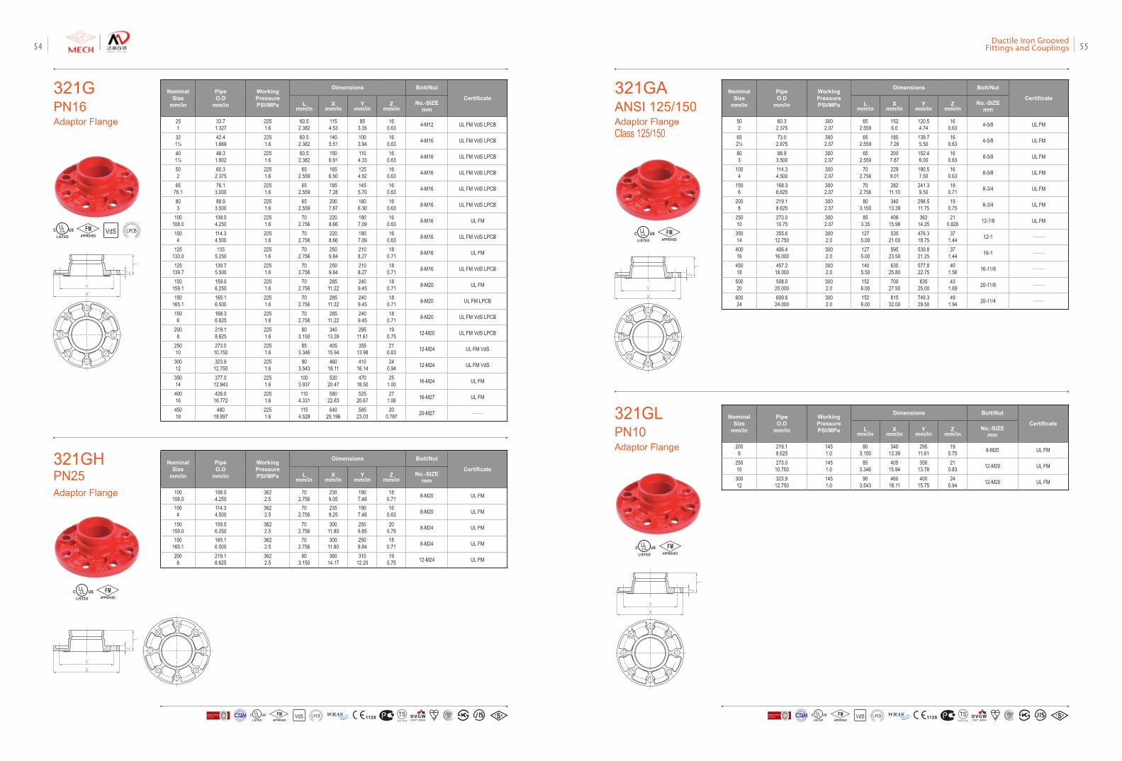
NominalSize
mm/in
PipeO.D
mm/in
Working PressurePSI/MPa
Dimensions Bolt/Nut
CertificateL
mm/inX
mm/inY
mm/inZ
mm/inNo.-SIZE
mm
2008
219.18.625
1451.0
803.150
34013.39
29511.61
190.75 8-M20 UL FM
25010
273.010.750
1451.0
853.346
40515.94
35013.78
210.83 12-M20 UL FM
30012
323.912.750
1451.0
903.543
46018.11
40015.75
240.94 12-M20 UL FM
FMAPPROVED
321GLPN10Adaptor Flange
321GPN16Adaptor Flange
NominalSize
mm/in
PipeO.D
mm/in
Working PressurePSI/MPa
Dimensions Bolt/Nut
CertificateL
mm/inX
mm/inY
mm/inZ
mm/inNo.-SIZE
mm
251
33.71.327
2251.6
60.52.382
1154.53
853.35
160.63 4-M12 UL FM VdS LPCB
321¼
42.41.669
2251.6
60.52.382
1405.51
1003.94
160.63 4-M16 UL FM VdS LPCB
401½
48.31.902
2251.6
60.52.382
1506.91
1104.33
160.63 4-M16 UL FM VdS LPCB
502
60.32.375
2251.6
652.559
1656.50
1254.92
160.63 4-M16 UL FM VdS LPCB
6576.1
76.13.000
2251.6
652.559
1857.28
1455.70
160.63 4-M16 UL FM VdS LPCB
803
88.93.500
2251.6
652.559
2007.87
1606.30
160.63 8-M16 UL FM VdS LPCB
100108.0
108.04.250
2251.6
702.756
2208.66
1807.09
160.63 8-M16 UL FM
1004
114.34.500
2251.6
702.756
2208.66
1807.09
160.63 8-M16 UL FM VdS LPCB
125133.0
1335.250
2251.6
702.756
2509.84
2108.27
180.71 8-M16 UL FM
125139.7
139.75.500
2251.6
702.756
2509.84
2108.27
180.71 8-M16 UL FM VdS LPCB
150159.1
159.06.250
2251.6
702.756
28511.22
2409.45
180.71 8-M20 UL FM
150165.1
165.16.500
2251.6
702.756
28511.22
2409.45
180.71 8-M20 UL FM LPCB
1506
168.36.625
2251.6
702.756
28511.22
2409.45
180.71 8-M20 UL FM VdS LPCB
2008
219.18.625
2251.6
803.150
34013.39
29511.61
190.75 12-M20 UL FM VdS LPCB
25010
273.010.750
2251.6
853.346
40515.94
35513.98
210.83 12-M24 UL FM VdS
30012
323.912.750
2251.6
903.543
46018.11
41016.14
240.94 12-M24 UL FM VdS
35014
377.012.843
2251.6
1003.937
52020.47
47018.50
251.00 16-M24 UL FM
40016
426.016.772
2251.6
1104.331
58022.83
52520.67
271.06 16-M27 UL FM
45018
48018.897
2251.6
1154.528
64025.196
58523.03
200.787 20-M27 ——
VdSFMAPPROVED LOSS
PRE
VENTIO
N CERTIFICATION
BOARD
321GAANSI 125/150Adaptor FlangeClass 125/150
NominalSize
mm/in
PipeO.D
mm/in
Working PressurePSI/MPa
Dimensions Bolt/Nut
CertificateL
mm/inX
mm/inY
mm/inZ
mm/inNo.-SIZE
mm
502
60.32.375
3002.07
652.559
1526.0
120.54.74
160.63 4-5/8 UL FM
652½
73.02.875
3002.07
652.559
1857.28
139.75.50
160.63 4-5/8 UL FM
803
88.93.500
3002.07
652.559
2007.87
152.46.00
160.63 8-5/8 UL FM
1004
114.34.500
3002.07
702.756
2299.01
190.57.50
160.63 8-5/8 UL FM
1506
168.36.625
3002.07
702.756
28211.10
241.39.50
180.71 8-3/4 UL FM
2008
219.18.625
3002.07
803.150
34013.39
298.511.75
190.75 8-3/4 UL FM
25010
273.010.75
3002.07
853.35
40615.98
36214.25
210.826 12-7/8 UL FM
35014
355.612.750
3002.0
1275.00
53521.00
476.318.75
371.44 12-1 ——
40016
406.416.000
3002.0
1275.00
59523.50
539.821.25
371.44 16-1 ——
45018
457.218.000
3002.0
1405.50
63525.80
577.822.75
401.56 16-11/8 ——
50020
508.020.000
3002.0
1526.00
70027.50
63525.00
431.69 20-11/8 ——
60024
609.624.000
3002.0
1526.00
81532.00
749.329.50
491.94 20-11/4 ——
FMAPPROVED
321GHPN25Adaptor Flange
NominalSize
mm/in
PipeO.D
mm/in
Working PressurePSI/MPa
Dimensions Bolt/Nut
CertificateL
mm/inX
mm/inY
mm/inZ
mm/inNo.-SIZE
mm
100108.0
108.04.250
3622.5
702.756
2309.05
1907.48
180.71 8-M20 UL FM
1004
114.34.500
3622.5
702.756
2359.25
1907.48
160.63 8-M20 UL FM
150159.0
159.06.250
3622.5
702.756
30011.80
2509.85
200.79 8-M24 UL FM
150165.1
165.16.500
3622.5
702.756
30011.80
2509.84
180.71 8-M24 UL FM
2008
219.18.625
3622.5
803.150
36014.17
31012.20
190.75 12-M24 UL FM
FMAPPROVED
VdS 1128 T STS2710Y44
WRASA P P R O V E D
P R O D U C TFM
APPROVED LOSS P
REVE
NTION CERTIFICATIO
N BO
ARD
CERTIF ICATIO
N
方
圆认证
BUREAU VERITASVdS 1128 T STS2710Y44
WRASA P P R O V E D
P R O D U C TFM
APPROVED LOSS P
REVE
NTION CERTIFICATIO
N BO
ARD
CERTIF ICATIO
N
方
圆认证
BUREAU VERITAS
Ductile Iron Grooved Fittings and Couplings 5554
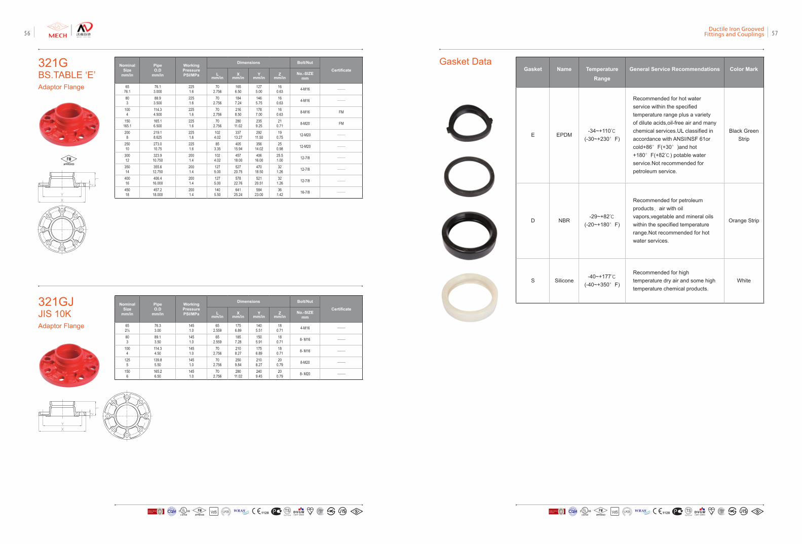
321GBS.TABLE ‘E’Adaptor Flange
NominalSize
mm/in
PipeO.D
mm/in
Working PressurePSI/MPa
Dimensions Bolt/Nut
CertificateL
mm/inX
mm/inY
mm/inZ
mm/inNo.-SIZE
mm
6576.1
76.13.000
2251.6
702.756
1656.50
1275.00
160.63 4-M16 ——
803
88.93.500
2251.6
702.756
1847.24
1465.75
160.63 4-M16 ——
1004
114.34.500
2251.6
702.756
2168.50
1787.00
160.63 8-M16 FM
150165.1
165.16.500
2251.6
702.756
28011.02
2359.25
210.71 8-M20 FM
2008
219.18.625
2251.6
1024.02
33713.27
29211.50
190.75 12-M20 ——
25010
273.010.75
2251.6
853.35
40515.94
35614.02
250.98 12-M20 ——
30012
323.910.750
2001.4
1024.02
45718.00
40616.00
25.51.00 12-7/8 ——
35014
355.612.750
2001.4
1275.00
52720.75
47018.50
321.26 12-7/8 ——
40016
406.416.000
2001.4
1275.00
57822.76
52120.51
321.26 12-7/8 ——
45018
457.218.000
2001.4
1405.50
64125.24
58423.00
361.42 16-7/8 ——
FMAPPROVED
321GJJIS 10KAdaptor Flange
NominalSize
mm/in
PipeO.D
mm/in
Working PressurePSI/MPa
Dimensions Bolt/Nut
CertificateL
mm/inX
mm/inY
mm/inZ
mm/inNo.-SIZE
mm
652½
76.33.00
1451.0
652.559
1756.89
1405.51
180.71 4-M16 ——
803
89.13.50
1451.0
652.559
1857.28
1505.91
180.71 8- M16 ——
1004
114.34.50
1451.0
702.756
2108.27
1756.89
180.71 8- M16 ——
1255
139.85.50
1451.0
702.756
2509.84
2108.27
200.79 8-M20 ——
1506
165.26.50
1451.0
702.756
28011.02
2409.45
200.79 8- M20 ——
Gasket DataGasket Name Temperature
Range
General Service Recommendations Color Mark
E EPDM-34~+110℃
(-30~+230°F)
Recommended for hot water service within the specified temperature range plus a variety of dilute acids,oil-free air and many chemical services.UL classified in accordance with ANSI/NSF 61or cold+86°F(+30°)and hot+180°F(+82℃) potable water service.Not recommended for petroleum service.
Black Green Strip
D NBR-29~+82℃
(-20~+180°F)
Recommended for petroleum products,air with oil vapors,vegetable and mineral oils within the specified temperature range.Not recommended for hot water services.
Orange Strip
S Silicone-40~+177℃
(-40~+350°F)
Recommended for high temperature dry air and some high temperature chemical products.
White
VdS 1128 T STS2710Y44
WRASA P P R O V E D
P R O D U C TFM
APPROVED LOSS P
REVE
NTION CERTIFICATIO
N BO
ARD
CERTIF ICATIO
N
方
圆认证
BUREAU VERITASVdS 1128 T STS2710Y44
WRASA P P R O V E D
P R O D U C TFM
APPROVED LOSS P
REVE
NTION CERTIFICATIO
N BO
ARD
CERTIF ICATIO
N
方
圆认证
BUREAU VERITAS
Ductile Iron Grooved Fittings and Couplings 5756
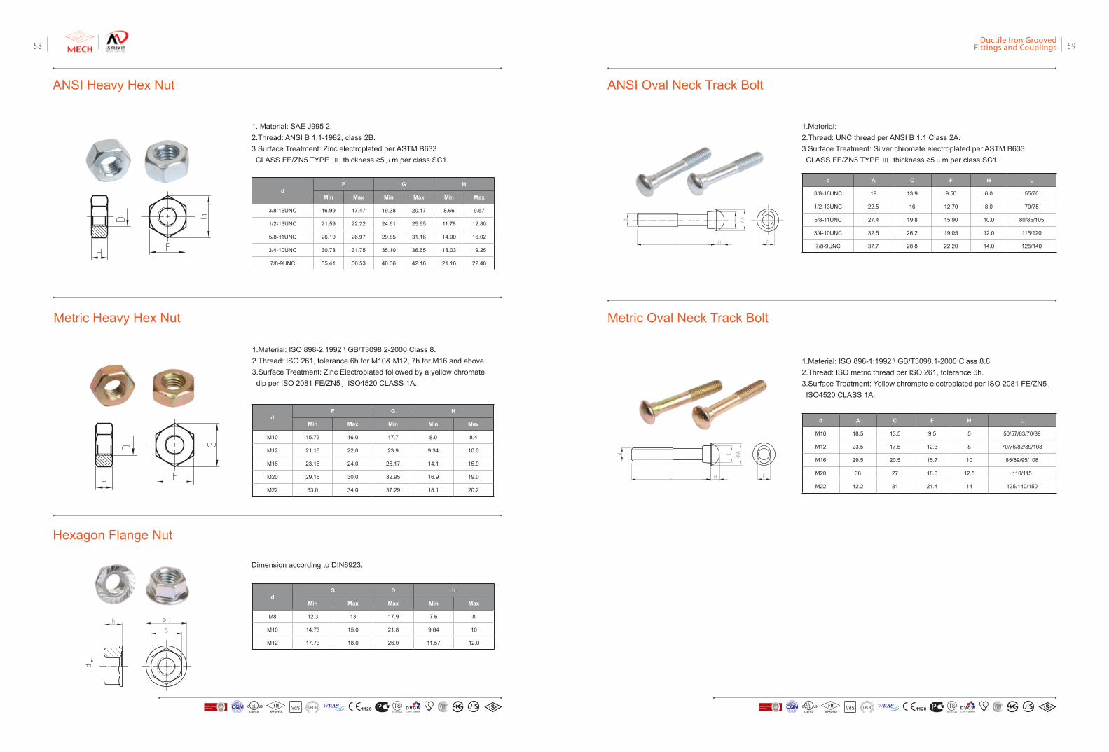
ANSI Heavy Hex Nut
1. Material: SAE J995 2. 2.Thread: ANSI B 1.1-1982, class 2B. 3.Surface Treatment: Zinc electroplated per ASTM B633 CLASS FE/ZN5 TYPE Ⅲ, thickness ≥5μm per class SC1.
dF G H
Min Max Min Max Min Max
3/8-16UNC 16.99 17.47 19.38 20.17 8.66 9.57
1/2-13UNC 21.59 22.22 24.61 25.65 11.78 12.80
5/8-11UNC 26.19 26.97 29.85 31.16 14.90 16.02
3/4-10UNC 30.78 31.75 35.10 36.65 18.03 19.25
7/8-9UNC 35.41 36.53 40.36 42.16 21.16 22.48
Metric Heavy Hex Nut
Hexagon Flange Nut
1.Material: ISO 898-2:1992 \ GB/T3098.2-2000 Class 8.2.Thread: ISO 261, tolerance 6h for M10& M12, 7h for M16 and above.3.Surface Treatment: Zinc Electroplated followed by a yellow chromate dip per ISO 2081 FE/ZN5,ISO4520 CLASS 1A.
dF G H
Min Max Min Min Max
M10 15.73 16.0 17.7 8.0 8.4
M12 21.16 22.0 23.9 9.34 10.0
M16 23.16 24.0 26.17 14.1 15.9
M20 29.16 30.0 32.95 16.9 19.0
M22 33.0 34.0 37.29 18.1 20.2
Dimension according to DIN6923.
dS D h
Min Max Max Min Max
M8 12.3 13 17.9 7.6 8
M10 14.73 15.0 21.8 9.64 10
M12 17.73 18.0 26.0 11.57 12.0
ANSI Oval Neck Track Bolt
1.Material: 2.Thread: UNC thread per ANSI B 1.1 Class 2A. 3.Surface Treatment: Silver chromate electroplated per ASTM B633 CLASS FE/ZN5 TYPE Ⅲ, thickness ≥5μm per class SC1.
d A C F H L
3/8-16UNC 19 13.9 9.50 6.0 55/70
1/2-13UNC 22.5 16 12.70 8.0 70/75
5/8-11UNC 27.4 19.8 15.90 10.0 80/85/105
3/4-10UNC 32.5 26.2 19.05 12.0 115/120
7/8-9UNC 37.7 28.8 22.20 14.0 125/140
Metric Oval Neck Track Bolt
1.Material: ISO 898-1:1992 \ GB/T3098.1-2000 Class 8.8.2.Thread: ISO metric thread per ISO 261, tolerance 6h.3.Surface Treatment: Yellow chromate electroplated per ISO 2081 FE/ZN5, ISO4520 CLASS 1A.
d A C F H L
M10 18.5 13.5 9.5 5 50/57/63/70/89
M12 23.5 17.5 12.3 8 70/76/82/89/108
M16 29.5 20.5 15.7 10 85/89/95/108
M20 38 27 18.3 12.5 110/115
M22 42.2 31 21.4 14 125/140/150
VdS 1128 T STS2710Y44
WRASA P P R O V E D
P R O D U C TFM
APPROVED LOSS P
REVE
NTION CERTIFICATIO
N BO
ARD
CERTIF ICATIO
N
方
圆认证
BUREAU VERITASVdS 1128 T STS2710Y44
WRASA P P R O V E D
P R O D U C TFM
APPROVED LOSS P
REVE
NTION CERTIFICATIO
N BO
ARD
CERTIF ICATIO
N
方
圆认证
BUREAU VERITAS
Ductile Iron Grooved Fittings and Couplings 5958
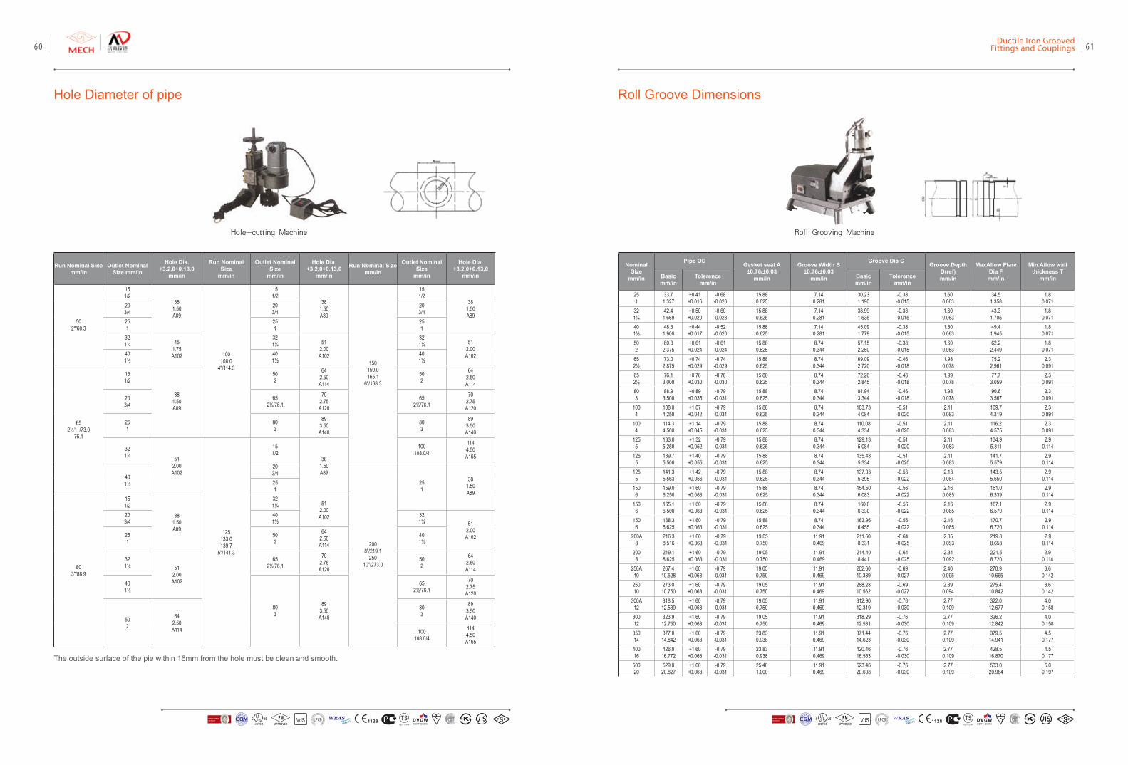
Hole Diameter of pipe
Hole-cutting Machine
Run Nominal Sinemm/in
Outlet Nominal Size mm/in
Hole Dia.+3.2,0+0.13,0
mm/in
Run Nominal Size
mm/in
Outlet Nominal Size
mm/in
Hole Dia.+3.2,0+0.13,0
mm/in
Run Nominal Sizemm/in
Outlet Nominal Size
mm/in
Hole Dia.+3.2,0+0.13,0
mm/in
502"/60.3
151/2
381.50A89
100108.0
4"/114.3
151/2
381.50A89
150159.0165.1
6"/168.3
151/2
381.50A89
203/4
203/4
203/4
251
251
251
321¼ 45
1.75A102
321¼ 51
2.00A102
321¼ 51
2.00A10240
1½401½
401½
652½”/73.0
76.1
151/2
381.50A89
502
642.50A114
502
642.50A114
203/4
652½/76.1
702.75A120
652½/76.1
702.75A120
251
803
893.50A140
803
893.50A140
321¼ 51
2.00A102
125133.0139.7
5"/141.3
151/2
381.50A89
100108.0/4
1144.50A165
203/4
2008"/219.1
25010"/273.0
251
381.50A89
401½ 25
1
803"/88.9
151/2
381.50A89
321¼ 51
2.00A10220
3/4401½
321¼ 51
2.00A10225
1502
642.50A114
401½
321¼ 51
2.00A102
652½/76.1
702.75A120
502
642.50A114
401½
803
893.50A140
652½/76.1
702.75A120
502
642.50A114
803
893.50A140
100108.0/4
1144.50A165
Roll Groove Dimensions
Nominal Size
mm/in
Pipe OD Gasket seat A±0.76/±0.03
mm/in
Groove Width B±0.76/±0.03
mm/in
Groove Dia C Groove Depth D(ref)mm/in
MaxAllow Flare Dia Fmm/in
Min.Allow wall thickness T
mm/inBasicmm/in
Tolerencemm/in
Basicmm/in
Tolerencemm/in
251
33.71.327
+0.41+0.016
-0.68-0.026
15.880.625
7.140.281
30.231.190
-0.38-0.015
1.600.063
34.51.358
1.80.071
321¼
42.41.669
+0.50+0.020
-0.60-0.023
15.880.625
7.140.281
38.991.535
-0.38-0.015
1.600.063
43.31.705
1.80.071
401½
48.31.900
+0.44+0.017
-0.52-0.020
15.880.625
7.140.281
45.091.779
-0.38-0.015
1.600.063
49.41.945
1.80.071
502
60.32.375
+0.61+0.024
-0.61-0.024
15.880.625
8.740.344
57.152.250
-0.38-0.015
1.600.063
62.22.449
1.80.071
652½
73.02.875
+0.74+0.029
-0.74-0.029
15.880.625
8.740.344
69.092.720
-0.46-0.018
1.980.078
75.22.961
2.30.091
652½
76.13.000
+0.76+0.030
-0.76-0.030
15.880.625
8.740.344
72.262.845
-0.46-0.018
1.990.078
77.73.059
2.30.091
803
88.93.500
+0.89+0.035
-0.79-0.031
15.880.625
8.740.344
84.943.344
-0.46-0.018
1.980.078
90.63.567
2.30.091
1004
108.04.250
+1.07+0.042
-0.79-0.031
15.880.625
8.740.344
103.734.084
-0.51-0.020
2.110.083
109.74.319
2.30.091
1004
114.34.500
+1.14+0.045
-0.79-0.031
15.880.625
8.740.344
110.084.334
-0.51-0.020
2.110.083
116.24.575
2.30.091
1255
133.05.250
+1.32+0.052
-0.79-0.031
15.880.625
8.740.344
129.135.084
-0.51-0.020
2.110.083
134.95.311
2.90.114
1255
139.75.500
+1.40+0.055
-0.79-0.031
15.880.625
8.740.344
135.485.334
-0.51-0.020
2.110.083
141.75.579
2.90.114
1255
141.35.563
+1.42+0.056
-0.79-0.031
15.880.625
8.740.344
137.035.395
-0.56-0.022
2.130.084
143.55.650
2.90.114
1506
159.06.250
+1.60+0.063
-0.79-0.031
15.880.625
8.740.344
154.506.083
-0.56-0.022
2.160.085
161.06.339
2.90.114
1506
165.16.500
+1.60+0.063
-0.79-0.031
15.880.625
8.740.344
160.86.330
-0.56-0.022
2.160.085
167.16.579
2.90.114
1506
168.36.625
+1.60+0.063
-0.79-0.031
15.880.625
8.740.344
163.966.455
-0.56-0.022
2.160.085
170.76.720
2.90.114
200A8
216.38.516
+1.60+0.063
-0.79-0.031
19.050.750
11.910.469
211.608.331
-0.64-0.025
2.350.093
219.88.653
2.90.114
2008
219.18.625
+1.60+0.063
-0.79-0.031
19.050.750
11.910.469
214.408.441
-0.64-0.025
2.340.092
221.58.720
2.90.114
250A10
267.410.528
+1.60+0.063
-0.79-0.031
19.050.750
11.910.469
262.6010.339
-0.69-0.027
2.400.095
270.910.665
3.60.142
25010
273.010.750
+1.60+0.063
-0.79-0.031
19.050.750
11.910.469
268.2810.562
-0.69-0.027
2.390.094
275.410.842
3.60.142
300A12
318.512.539
+1.60+0.063
-0.79-0.031
19.050.750
11.910.469
312.9012.319
-0.76-0.030
2.770.109
322.012.677
4.00.158
30012
323.912.750
+1.60+0.063
-0.79-0.031
19.050.750
11.910.469
318.2912.531
-0.76-0.030
2.770.109
326.212.842
4.00.158
35014
377.014.842
+1.60+0.063
-0.79-0.031
23.830.938
11.910.469
371.4414.623
-0.76-0.030
2.770.109
379.514.941
4.50.177
40016
426.016.772
+1.60+0.063
-0.79-0.031
23.830.938
11.910.469
420.4616.553
-0.76-0.030
2.770.109
428.516.870
4.50.177
50020
529.020.827
+1.60+0.063
-0.79-0.031
25.401.000
11.910.469
523.4620.608
-0.76-0.030
2.770.109
533.020.984
5.00.197
Roll Grooving Machine
The outside surface of the pie within 16mm from the hole must be clean and smooth.
VdS 1128 T STS2710Y44
WRASA P P R O V E D
P R O D U C TFM
APPROVED LOSS P
REVE
NTION CERTIFICATIO
N BO
ARD
CERTIF ICATIO
N
方
圆认证
BUREAU VERITASVdS 1128 T STS2710Y44
WRASA P P R O V E D
P R O D U C TFM
APPROVED LOSS P
REVE
NTION CERTIFICATIO
N BO
ARD
CERTIF ICATIO
N
方
圆认证
BUREAU VERITAS
Ductile Iron Grooved Fittings and Couplings 6160
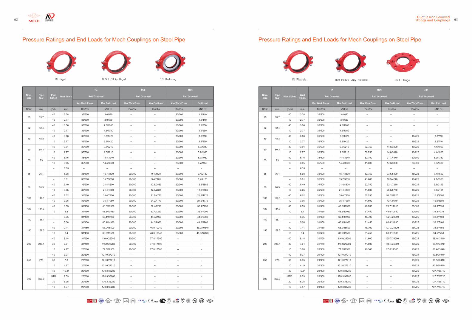
Pressure Ratings and End Loads for Mech Couplings on Steel Pipe Pressure Ratings and End Loads for Mech Couplings on Steel Pipe
1G Rigid 1GS L/Duty Rigid 1N Reducing
Nom. Size
Pipe O.D
Pipe Sched Wall Thick.
1G 1GS 1NR
Roll Grooved Roll Grooved Roll Grooved
Max.Work Press. Max.End Load Max.Work Press. Max.End Load Max.Work Press. End Load
DN/in mm (Sch) mm Bar/Psi kN/Lbs Bar/Psi kN/Lbs Bar/Psi kN/Lbs
25 33.740 3.38 35/500 3.0/680 -- -- 20/300 1.8/410
10 2.77 35/500 3.0/680 -- -- 20/300 1.8/410
32 42.440 3.56 35/500 4.8/1080 -- -- 20/300 2.9/650
10 2.77 35/500 4.8/1080 -- -- 20/300 2.9/650
40 48.340 3.68 35/500 6.3/1420 -- -- 20/300 3.8/850
10 2.77 35/500 6.3/1420 -- -- 20/300 3.8/850
50 60.340 3.91 35/500 9.8/2210 -- -- 20/300 5.9/1330
10 2.77 35/500 9.8/2210 -- -- 20/300 5.9/1330
65 7340 5.16 35/500 14.4/3240 -- -- 20/300 8.7/1950
10 3.05 35/500 14.4/3240 -- -- 20/300 8.7/1950
65 76.1
-- 6.35 -- -- -- -- -- --
-- 5.08 35/500 15.7/3530 20/300 9.4/2120 20/300 9.4/2120
-- 3.81 35/500 15.7/3530 20/300 9.4/2120 20/300 9.4/2120
80 88.940 5.49 35/500 21.4/4800 20/300 12.8/2885 20/300 12.8/2885
10 3.05 35/500 21.4/4800 20/300 12.8/2885 20/300 12.8/2885
100 114.340 6.02 35/500 35.4/7950 20/300 21.2/4770 20/300 21.2/4770
10 3.05 35/500 35.4/7950 20/300 21.2/4770 20/300 21.2/4770
125 141.340 6.55 31/450 48.6/10930 20/300 32.4/7290 20/300 32.4/7290
10 3.4 31/450 48.6/10930 20/300 32.4/7290 20/300 32.4/7290
150 165.1-- 6.35 31/450 66.4/14930 20/300 44.3/9960 20/300 44.3/9960
-- 5.08 31/450 66.4/14930 20/300 44.3/9960 20/300 44.3/9960
150 168.340 7.11 31/450 68.9/15500 20/300 46.0/10340 20/300 46.0/10340
10 3.4 31/450 68.9/15500 20/300 46.0/10340 20/300 46.0/10340
200 219.1
40 8.18 31/450 116.9/26280 20/300 77.8/17500 -- --
30 7.04 31/450 116.9/26280 20/300 77.8/17500 -- --
10 4.77 20/300 77.8/17500 20/300 77.8/17500 -- --
250 273
40 9.27 20/300 121.0/27210 -- -- -- --
30 7.8 20/300 121.0/27210 -- -- -- --
10 4.77 20/300 121.0/27210 -- -- -- --
300 323.9
40 10.31 20/300 170.3/38280 -- -- -- --
STD 9.53 20/300 170.3/38280 -- -- -- --
30 6.35 20/300 170.3/38280 -- -- -- --
10 4.77 20/300 170.3/38280 -- -- -- --
1N Flexible 1NH Heavy Duty Flexible 321 Flange
Nom. Size
Pipe O.D Pipe Sched Wall
Thick.
1N 1NH 321
Roll Grooved Roll Grooved Roll Grooved
Max.Work Press. Max.End Load Max.Work Press. Max.End Load Max.Work Press. Max.End Load
DN/in mm (Sch) mm Bar/Psi kN/Lbs Bar/Psi kN/Lbs Bar/Psi kN/Lbs
25 33.740 3.38 35/500 3.0/680 -- -- -- --
10 2.77 35/500 3.0/680 -- -- -- --
32 42.440 3.56 35/500 4.8/1080 -- -- -- --
10 2.77 35/500 4.8/1080 -- -- -- --
40 48.340 3.56 35/500 6.3/1420 -- -- 16/225 3.2/710
10 2.77 35/500 6.3/1420 -- -- 16/225 3.2/710
50 60.340 3.91 35/500 9.8/2210 52/750 14.8/3320 16/225 4.4/1000
10 2.77 35/500 9.8/2210 52/750 14.8/3320 16/225 4.4/1000
65 7340 5.16 35/500 14.4/3240 52/750 21.7/4870 20/300 5.9/1330
10 3.05 35/500 14.4/3240 41/600 17.3/3900 20/300 5.9/1330
65 76.1
-- 6.35 -- -- -- -- -- --
-- 5.08 35/500 15.7/3530 52/750 23.6/5300 16/225 7.1/1590
-- 3.81 35/500 15.7/3530 41/600 18.9/4240 16/225 7.1/1590
80 88.940 5.49 35/500 21.4/4800 52/750 32.1/7210 16/225 9.6/2165
10 3.05 35/500 21.4/4800 41/600 25.6/5760 16/225 9.6/2165
100 114.340 6.02 35/500 35.4/7950 52/750 53.0/11920 16/225 15.9/3580
10 3.05 35/500 35.4/7950 41/600 42.4/9540 16/225 15.9/3580
125 141.340 6.55 31/450 48.6/10930 48/700 75.7/17010 20/300 31.3/7035
10 3.4 31/450 48.6/10930 31/450 48.6/10930 20/300 31.3/7035
150 165.1-- 6.35 31/450 66.4/14930 48/700 102.7/23090 16/225 33.2/7460
-- 5.08 31/450 66.4/14930 31/450 66.4/14930 16/225 33.2/7460
150 168.340 7.11 31/450 68.9/15500 48/700 107.3/24120 16/225 34.5/7750
10 3.4 31/450 68.9/15500 31/450 68.9/15500 16/225 34.5/7750
200 219.1
40 8.18 31/450 116.9/26280 41/600 155.7/35000 16/225 58.4/13140
30 7.04 31/450 116.9/26280 41/600 155.7/35000 16/225 58.4/13140
10 3.76 20/300 77.8/17500 20/300 77.8/17500 16/225 58.4/13140
250 273
40 9.27 20/300 121.0/27210 -- -- 16/225 90.8/20410
30 6.35 20/300 121.0/27210 -- -- 16/225 90.8/20410
10 4.19 20/300 121.0/27210 -- -- 16/225 90.8/20410
300 323.9
40 10.31 20/300 170.3/38280 -- -- 16/225 127.7/28710
STD 9.53 20/300 170.3/38280 -- -- 16/225 127.7/28710
20 6.35 20/300 170.3/38280 -- -- 16/225 127.7/28710
10 4.57 20/300 170.3/38280 -- -- 16/225 127.7/28710
VdS 1128 T STS2710Y44
WRASA P P R O V E D
P R O D U C TFM
APPROVED LOSS P
REVE
NTION CERTIFICATIO
N BO
ARD
CERTIF ICATIO
N
方
圆认证
BUREAU VERITASVdS 1128 T STS2710Y44
WRASA P P R O V E D
P R O D U C TFM
APPROVED LOSS P
REVE
NTION CERTIFICATIO
N BO
ARD
CERTIF ICATIO
N
方
圆认证
BUREAU VERITAS
Ductile Iron Grooved Fittings and Couplings 6362
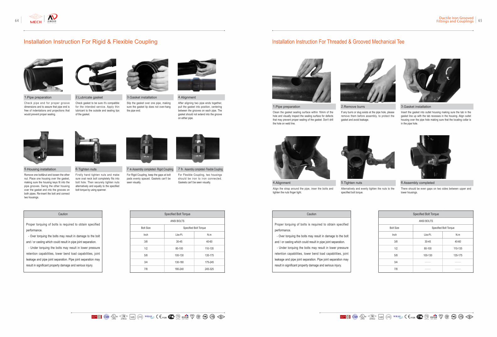
Installation Instruction For Rigid & Flexible Coupling Installation Instruction For Threaded & Grooved Mechanical Tee
1.Pipe preparation
5.Housing installation
2.Lubricate gasket 3.Gasket installation
7 a.Assembly completed- Rigid Coupling
4.Alignment
1.Pipe preparation
4.Alignment
2.Remove burrs
5.Tighten nuts
3.Gasket installation
6.Assembly completed
7 b. Assembly completed- Flexible Coupling
Check p ipe end for proper groove dimensions and to assure that pipe end is free of indentations and projections that would prevent proper sealing.
Romove one bolt&nut and loosen the other nut. Place one housing over the gasket, making sure the housing keys fit into the pipe grooves. Swing the other housing over the gasket and into the grooves on both pipes. Re-insert the bolt and connect two housings.
Check gasket to be sure it's compatible for the intended service. Apply thin lubricant to the outside and sealing lips of the gasket.
Firstly hand tighten nuts and make sure oval neck bolt completely fits into bolt hole. Then securely tighten nuts alternatively and equally to the specified bolt torque by using spanner.
Slip the gasket over one pipe, making sure the gasket lip does not over-hang the pipe end.
For Rigid Coupling, keep the gaps at bolt pads evenly spaced. Gaskets can't be seen visually.
After aligning two pipe ends together, pull the gasket into position, centering between the grooves on each pipe. The gasket should not extend into the groove on either pipe.
Clean the gasket sealing surface within 16mm of the hole and visually inspect the sealing surface for defects that may prevent proper sealing of the gasket. Don't drill the hole on weld line.
Align the strap around the pipe, inser the bolts and tighten the nuts finger tight.
If any burrs or slug exists at the pipe hole, please remove them before assembly, to protect the gasket and avoid leakage.
Alternatively and evenly tighten the nuts to the specified bolt torque.
Insert the gasket into outlet housing making sure the tab in the gasket line up with the tab recesses in the housing. Align outlet housing over the pipe hole making sure that the locating collar is in the pipe hole.
There should be even gaps on two sides between upper and lower housings.
For Flexible Coupling, two housings should be i ron to i ron connected. Gaskets can't be seen visually.
Caution
Proper torquing of bolts is required to obtain specified
performance.
- Over torquing the bolts may result in damage to the bolt
and / or casting which could result in pipe joint separation.
- Under torquing the bolts may result in lower pressure
retention capabilities, lower bend load capabilities, joint
leakage and pipe joint separation. Pipe joint separation may
result in significant property damage and serious injury.
Specified Bolt Torque
ANSI BOLTS
Bolt Size Specified Bolt Torque
Inch Lbs-Ft. N.m
3/8 30-45 40-60
1/2 80-100 110-135
5/8 100-130 135-175
3/4 130-180 175-245
7/8 180-240 245-325
Specified Bolt Torque
ANSI BOLTS
Bolt Size Specified Bolt Torque
Inch Lbs-Ft. N.m
3/8 30-45 40-60
1/2 80-100 110-135
5/8 100-130 135-175
3/4 —— ——
7/8 —— ——
6.Tighten nuts
VdS 1128 T STS2710Y44
WRASA P P R O V E D
P R O D U C TFM
APPROVED LOSS P
REVE
NTION CERTIFICATIO
N BO
ARD
CERTIF ICATIO
N
方
圆认证
BUREAU VERITASVdS 1128 T STS2710Y44
WRASA P P R O V E D
P R O D U C TFM
APPROVED LOSS P
REVE
NTION CERTIFICATIO
N BO
ARD
CERTIF ICATIO
N
方
圆认证
BUREAU VERITAS
Ductile Iron Grooved Fittings and Couplings 6564
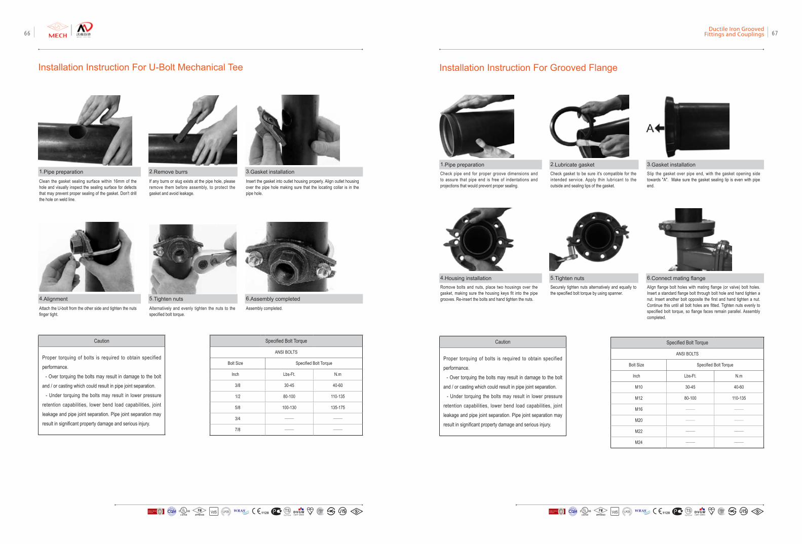
Installation Instruction For U-Bolt Mechanical Tee
1.Pipe preparation
4.Alignment
2.Remove burrs
5.Tighten nuts
3.Gasket installation
6.Assembly completed
Clean the gasket sealing surface within 16mm of the hole and visually inspect the sealing surface for defects that may prevent proper sealing of the gasket. Don't drill the hole on weld line.
Attach the U-bolt from the other side and tighten the nuts finger tight.
If any burrs or slug exists at the pipe hole, please remove them before assembly, to protect the gasket and avoid leakage.
Alternatively and evenly tighten the nuts to the specified bolt torque.
Insert the gasket into outlet housing properly. Align outlet housing over the pipe hole making sure that the locating collar is in the pipe hole.
Assembly completed.
Specified Bolt Torque
ANSI BOLTS
Bolt Size Specified Bolt Torque
Inch Lbs-Ft. N.m
3/8 30-45 40-60
1/2 80-100 110-135
5/8 100-130 135-175
3/4 —— ——
7/8 —— ——
Installation Instruction For Grooved Flange
1.Pipe preparation
4.Housing installation
2.Lubricate gasket
5.Tighten nuts
3.Gasket installation
6.Connect mating flange
Check pipe end for proper groove dimensions and to assure that pipe end is free of indentations and projections that would prevent proper sealing.
Romove bolts and nuts, place two housings over the gasket, making sure the housing keys fit into the pipe grooves. Re-insert the bolts and hand tighten the nuts.
Check gasket to be sure it's compatible for the intended service. Apply thin lubricant to the outside and sealing lips of the gasket.
Securely tighten nuts alternatively and equally to the specified bolt torque by using spanner.
Slip the gasket over pipe end, with the gasket opening side towards "A". Make sure the gasket sealing lip is even with pipe end.
Align flange bolt holes with mating flange (or valve) bolt holes. Insert a standard flange bolt through bolt hole and hand tighten a nut. Insert another bolt opposite the first and hand tighten a nut. Continue this until all bolt holes are fitted. Tighten nuts evenly to specified bolt torque, so flange faces remain parallel. Assembly completed.
Specified Bolt Torque
ANSI BOLTS
Bolt Size Specified Bolt Torque
Inch Lbs-Ft. N.m
M10 30-45 40-60
M12 80-100 110-135
M16 —— ——
M20 —— ——
M22 —— ——
M24 —— ——
Caution
Proper torquing of bolts is required to obtain specified
performance.
- Over torquing the bolts may result in damage to the bolt
and / or casting which could result in pipe joint separation.
- Under torquing the bolts may result in lower pressure
retention capabilities, lower bend load capabilities, joint
leakage and pipe joint separation. Pipe joint separation may
result in significant property damage and serious injury.
VdS 1128 T STS2710Y44
WRASA P P R O V E D
P R O D U C TFM
APPROVED LOSS P
REVE
NTION CERTIFICATIO
N BO
ARD
CERTIF ICATIO
N
方
圆认证
BUREAU VERITASVdS 1128 T STS2710Y44
WRASA P P R O V E D
P R O D U C TFM
APPROVED LOSS P
REVE
NTION CERTIFICATIO
N BO
ARD
CERTIF ICATIO
N
方
圆认证
BUREAU VERITAS
Ductile Iron Grooved Fittings and Couplings 6766
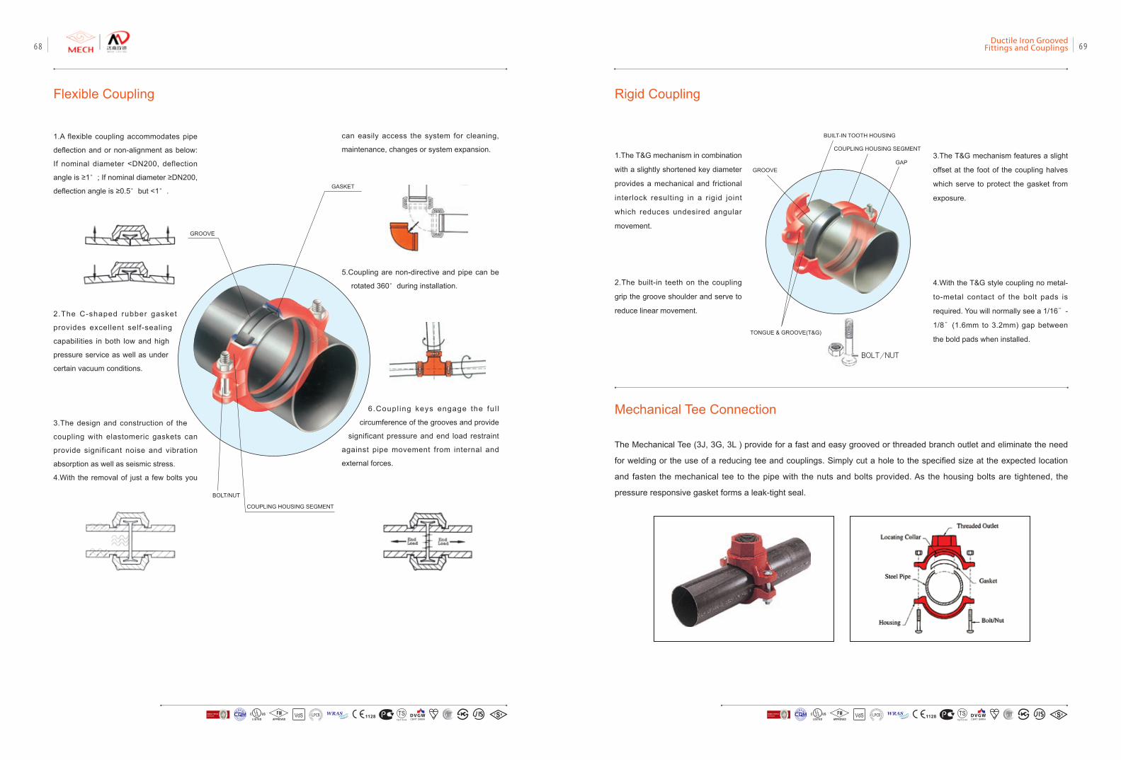
1.A flexible coupling accommodates pipe
deflection and or non-alignment as below:
If nominal diameter <DN200, deflection
angle is ≥1°; If nominal diameter ≥DN200,
deflection angle is ≥0.5°but <1°.
2.The C-shaped rubber gasket
provides excellent self-sealing
capabilities in both low and high
pressure service as well as under
certain vacuum conditions.
3.The design and construction of the
coupling with elastomeric gaskets can
provide significant noise and vibration
absorption as well as seismic stress.
4.With the removal of just a few bolts you
Flexible Coupling
can easily access the system for cleaning,
maintenance, changes or system expansion.
5.Coupling are non-directive and pipe can be
rotated 360°during installation.
6.Coupl ing keys engage the fu l l
circumference of the grooves and provide
significant pressure and end load restraint
against pipe movement from internal and
external forces.
GROOVE
GASKET
COUPLING HOUSING SEGMENT
BOLT/NUT
1.The T&G mechanism in combination
with a slightly shortened key diameter
provides a mechanical and frictional
interlock resulting in a rigid joint
which reduces undesired angular
movement.
2.The built-in teeth on the coupling
grip the groove shoulder and serve to
reduce linear movement.
Rigid Coupling
Mechanical Tee Connection
3.The T&G mechanism features a slight
offset at the foot of the coupling halves
which serve to protect the gasket from
exposure.
4.With the T&G style coupling no metal-
to-metal contact of the bolt pads is
required. You will normally see a 1/16”-
1/8”(1.6mm to 3.2mm) gap between
the bold pads when installed.
GROOVE
TONGUE & GROOVE(T&G)
BUILT-IN TOOTH HOUSING
COUPLING HOUSING SEGMENT
GAP
The Mechanical Tee (3J, 3G, 3L ) provide for a fast and easy grooved or threaded branch outlet and eliminate the need
for welding or the use of a reducing tee and couplings. Simply cut a hole to the specified size at the expected location
and fasten the mechanical tee to the pipe with the nuts and bolts provided. As the housing bolts are tightened, the
pressure responsive gasket forms a leak-tight seal.
BOLT/NUT
VdS 1128 T STS2710Y44
WRASA P P R O V E D
P R O D U C TFM
APPROVED LOSS P
REVE
NTION CERTIFICATIO
N BO
ARD
CERTIF ICATIO
N
方
圆认证
BUREAU VERITASVdS 1128 T STS2710Y44
WRASA P P R O V E D
P R O D U C TFM
APPROVED LOSS P
REVE
NTION CERTIFICATIO
N BO
ARD
CERTIF ICATIO
N
方
圆认证
BUREAU VERITAS
Ductile Iron Grooved Fittings and Couplings 6968
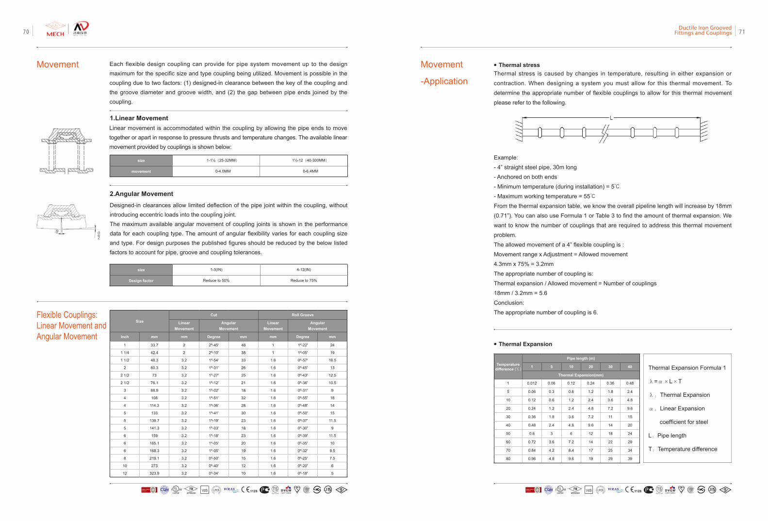
Movement
Linear movement is accommodated within the coupling by allowing the pipe ends to move together or apart in response to pressure thrusts and temperature changes. The available linear movement provided by couplings is shown below:
size 1-3(IN) 4-12(IN)
Design factor Reduce to 50% Reduce to 75%
1.Linear Movement
2.Angular Movement
size 1-1¼(25-32MM) 1½-12(40-300MM)
movement 0-4.0MM 0-6.4MM
Each flexible design coupling can provide for pipe system movement up to the design maximum for the specific size and type coupling being utilized. Movement is possible in the coupling due to two factors: (1) designed-in clearance between the key of the coupling and the groove diameter and groove width, and (2) the gap between pipe ends joined by the coupling.
Designed-in clearances allow limited deflection of the pipe joint within the coupling, without introducing eccentric loads into the coupling joint. The maximum available angular movement of coupling joints is shown in the performance data for each coupling type. The amount of angular flexibility varies for each coupling size and type. For design purposes the published figures should be reduced by the below listed factors to account for pipe, groove and coupling tolerances.
Movement
-Application
Thermal Expansion Formula 1
λ=α×L×T
λ:Thermal Expansion
α:Linear Expansion
coefficient for steel
L:Pipe length
T:Temperature difference
Thermal stress is caused by changes in temperature, resulting in either expansion or
contraction. When designing a system you must allow for this thermal movement. To
determine the appropriate number of flexible couplings to allow for this thermal movement
please refer to the following.
Temperature difference (℃)
Pipe length (m)
1 5 10 20 30 40
Thermal Expansion(mm)
1 0.012 0.06 0.12 0.24 0.36 0.48
5 0.06 0.3 0.6 1.2 1.8 2.4
10 0.12 0.6 1.2 2.4 3.6 4.8
20 0.24 1.2 2.4 4.8 7.2 9.6
30 0.36 1.8 3.6 7.2 11 15
40 0.48 2.4 4.8 9.6 14 20
50 0.6 3 6 12 18 24
60 0.72 3.6 7.2 14 22 29
70 0.84 4.2 8.4 17 25 34
80 0.96 4.8 9.6 19 29 39
• Thermal Expansion
Example:
- 4” straight steel pipe, 30m long
- Anchored on both ends
- Minimum temperature (during installation) = 5℃
- Maximum working temperature = 55℃
From the thermal expansion table, we know the overall pipeline length will increase by 18mm
(0.71”). You can also use Formula 1 or Table 3 to find the amount of thermal expansion. We
want to know the number of couplings that are required to address this thermal movement
problem.
The allowed movement of a 4” flexible coupling is :
Movement range x Adjustment = Allowed movement
4.3mm x 75% = 3.2mm
The appropriate number of coupling is:
Thermal expansion / Allowed movement = Number of couplings
18mm / 3.2mm = 5.6
Conclusion:
The appropriate number of coupling is 6.
• Thermal stress
Flexible Couplings: Linear Movement and Angular Movement
SizeCut Roll Groove
Linear Movement
Angular Movement
Linear Movement
Angular Movement
Inch mm mm Degree mm mm Degree mm
1 33.7 2 2º-45' 48 1 1º-22' 24
1 1/4 42.4 2 2º-10' 38 1 1º-05' 19
1 1/2 48.3 3.2 1º-54' 33 1.6 0º-57' 16.5
2 60.3 3.2 1º-31' 26 1.6 0º-45' 13
2 1/2 73 3.2 1º-27' 25 1.6 0º-43' 12.5
2 1/2 76.1 3.2 1º-12' 21 1.6 0º-36' 10.5
3 88.9 3.2 1º-02' 18 1.6 0º-31' 9
4 108 3.2 1º-51' 32 1.6 0º-55' 16
4 114.3 3.2 1º-36' 28 1.6 0º-48' 14
5 133 3.2 1º-41' 30 1.6 0º-50' 15
5 139.7 3.2 1º-19' 23 1.6 0º-37' 11.5
5 141.3 3.2 1º-03' 18 1.6 0º-30' 9
6 159 3.2 1º-18' 23 1.6 0º-39' 11.5
6 165.1 3.2 1º-05' 20 1.6 0º-35' 10
6 168.3 3.2 1º-05' 19 1.6 0º-32' 9.5
8 219.1 3.2 0º-50' 15 1.6 0º-25' 7.5
10 273 3.2 0º-40' 12 1.6 0º-20' 6
12 323.9 3.2 0º-34' 10 1.6 0º-18' 5
VdS 1128 T STS2710Y44
WRASA P P R O V E D
P R O D U C TFM
APPROVED LOSS P
REVE
NTION CERTIFICATIO
N BO
ARD
CERTIF ICATIO
N
方
圆认证
BUREAU VERITASVdS 1128 T STS2710Y44
WRASA P P R O V E D
P R O D U C TFM
APPROVED LOSS P
REVE
NTION CERTIFICATIO
N BO
ARD
CERTIF ICATIO
N
方
圆认证
BUREAU VERITAS
Ductile Iron Grooved Fittings and Couplings 7170
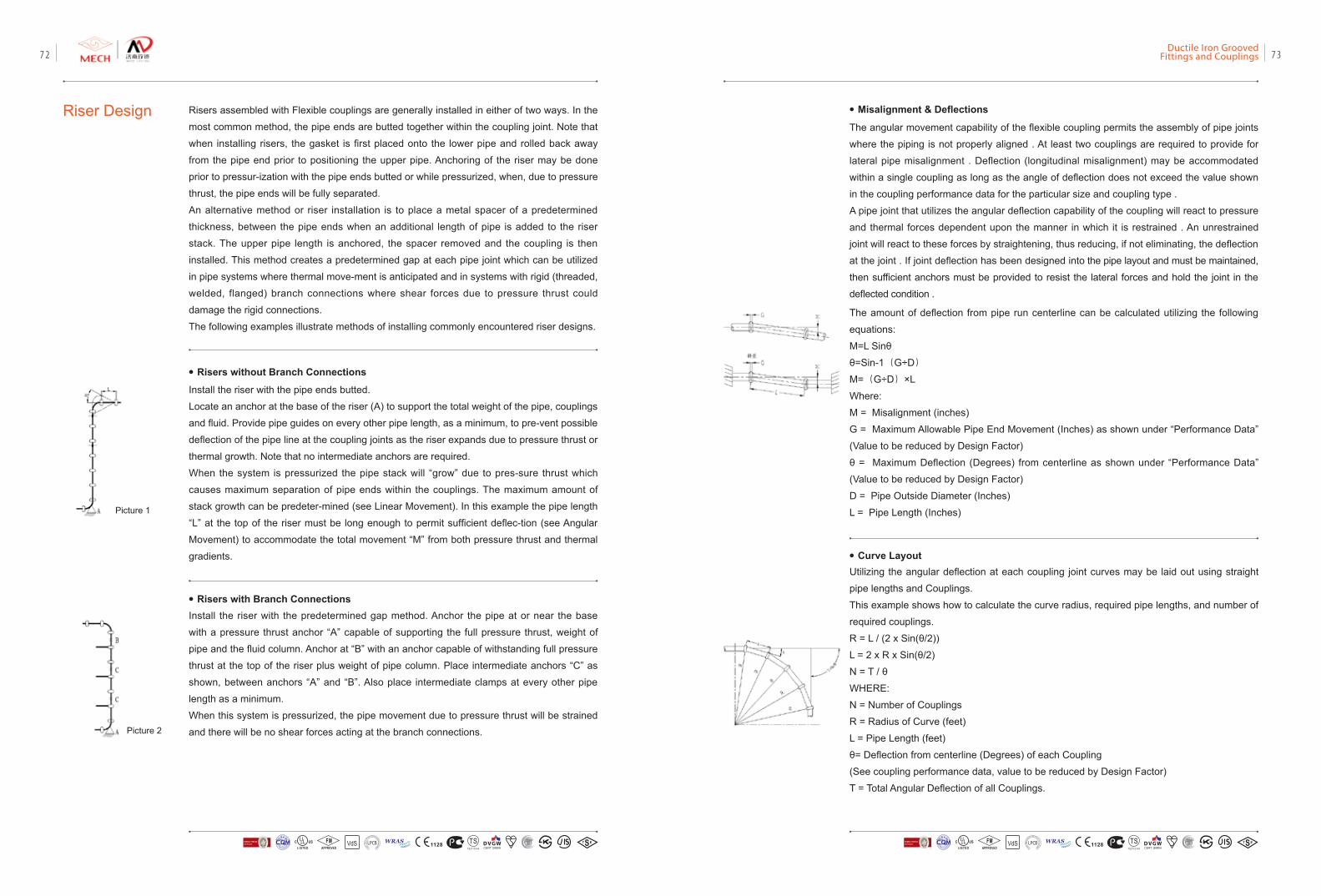
Riser Design Risers assembled with Flexible couplings are generally installed in either of two ways. In the
most common method, the pipe ends are butted together within the coupling joint. Note that
when installing risers, the gasket is first placed onto the lower pipe and rolled back away
from the pipe end prior to positioning the upper pipe. Anchoring of the riser may be done
prior to pressur-ization with the pipe ends butted or while pressurized, when, due to pressure
thrust, the pipe ends will be fully separated.
An alternative method or riser installation is to place a metal spacer of a predetermined
thickness, between the pipe ends when an additional length of pipe is added to the riser
stack. The upper pipe length is anchored, the spacer removed and the coupling is then
installed. This method creates a predetermined gap at each pipe joint which can be utilized
in pipe systems where thermal move-ment is anticipated and in systems with rigid (threaded,
welded, flanged) branch connections where shear forces due to pressure thrust could
damage the rigid connections.
The following examples illustrate methods of installing commonly encountered riser designs.
• Risers without Branch Connections
Install the riser with the pipe ends butted.
Locate an anchor at the base of the riser (A) to support the total weight of the pipe, couplings
and fluid. Provide pipe guides on every other pipe length, as a minimum, to pre-vent possible
deflection of the pipe line at the coupling joints as the riser expands due to pressure thrust or
thermal growth. Note that no intermediate anchors are required.
When the system is pressurized the pipe stack will “grow” due to pres-sure thrust which
causes maximum separation of pipe ends within the couplings. The maximum amount of
stack growth can be predeter-mined (see Linear Movement). In this example the pipe length
“L” at the top of the riser must be long enough to permit sufficient deflec-tion (see Angular
Movement) to accommodate the total movement “M” from both pressure thrust and thermal
gradients.
• Risers with Branch Connections Install the riser with the predetermined gap method. Anchor the pipe at or near the base
with a pressure thrust anchor “A” capable of supporting the full pressure thrust, weight of
pipe and the fluid column. Anchor at “B” with an anchor capable of withstanding full pressure
thrust at the top of the riser plus weight of pipe column. Place intermediate anchors “C” as
shown, between anchors “A” and “B”. Also place intermediate clamps at every other pipe
length as a minimum.
When this system is pressurized, the pipe movement due to pressure thrust will be strained
and there will be no shear forces acting at the branch connections.
Picture 1
Picture 2
• Misalignment & Deflections
The angular movement capability of the flexible coupling permits the assembly of pipe joints
where the piping is not properly aligned . At least two couplings are required to provide for
lateral pipe misalignment . Deflection (longitudinal misalignment) may be accommodated
within a single coupling as long as the angle of deflection does not exceed the value shown
in the coupling performance data for the particular size and coupling type .
A pipe joint that utilizes the angular deflection capability of the coupling will react to pressure
and thermal forces dependent upon the manner in which it is restrained . An unrestrained
joint will react to these forces by straightening, thus reducing, if not eliminating, the deflection
at the joint . If joint deflection has been designed into the pipe layout and must be maintained,
then sufficient anchors must be provided to resist the lateral forces and hold the joint in the
deflected condition .
Utilizing the angular deflection at each coupling joint curves may be laid out using straight
pipe lengths and Couplings.
This example shows how to calculate the curve radius, required pipe lengths, and number of
required couplings.
R = L / (2 x Sin(θ/2))
L = 2 x R x Sin(θ/2)
N = T / θ
WHERE:
N = Number of Couplings
R = Radius of Curve (feet)
L = Pipe Length (feet)
θ= Deflection from centerline (Degrees) of each Coupling
(See coupling performance data, value to be reduced by Design Factor)
T = Total Angular Deflection of all Couplings.
The amount of deflection from pipe run centerline can be calculated utilizing the following
equations:
M=L Sinθ
θ=Sin-1(G÷D)
M=(G÷D)×L
Where:
M = Misalignment (inches)
G = Maximum Allowable Pipe End Movement (Inches) as shown under “Performance Data”
(Value to be reduced by Design Factor)
θ = Maximum Deflection (Degrees) from centerline as shown under “Performance Data”
(Value to be reduced by Design Factor)
D = Pipe Outside Diameter (Inches)
L = Pipe Length (Inches)
• Curve Layout
VdS 1128 T STS2710Y44
WRASA P P R O V E D
P R O D U C TFM
APPROVED LOSS P
REVE
NTION CERTIFICATIO
N BO
ARD
CERTIF ICATIO
N
方
圆认证
BUREAU VERITASVdS 1128 T STS2710Y44
WRASA P P R O V E D
P R O D U C TFM
APPROVED LOSS P
REVE
NTION CERTIFICATIO
N BO
ARD
CERTIF ICATIO
N
方
圆认证
BUREAU VERITAS
Ductile Iron Grooved Fittings and Couplings 7372
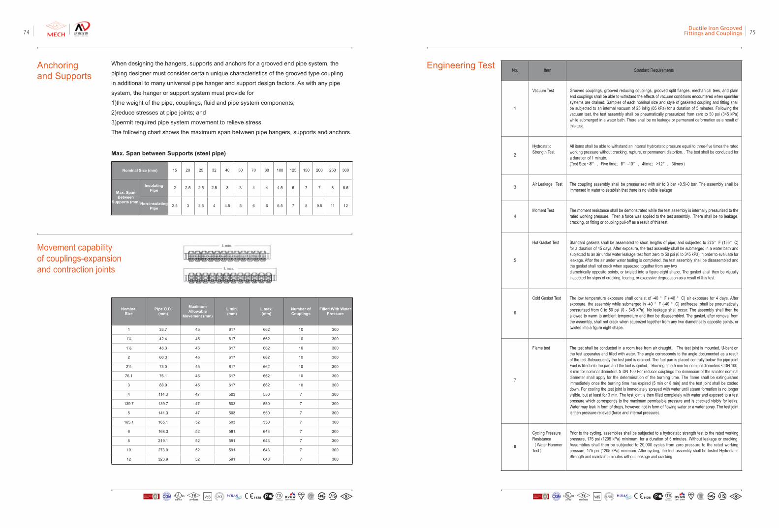
Anchoring and Supports
When designing the hangers, supports and anchors for a grooved end pipe system, the
piping designer must consider certain unique characteristics of the grooved type coupling
in additional to many universal pipe hanger and support design factors. As with any pipe
system, the hanger or support system must provide for
1)the weight of the pipe, couplings, fluid and pipe system components;
2)reduce stresses at pipe joints; and
3)permit required pipe system movement to relieve stress.
The following chart shows the maximum span between pipe hangers, supports and anchors.
Nominal Size (mm) 15 20 25 32 40 50 70 80 100 125 150 200 250 300
Max. Span Between
Supports (mm)
Insulating Pipe 2 2.5 2.5 2.5 3 3 4 4 4.5 6 7 7 8 8.5
Non-insulating Pipe 2.5 3 3.5 4 4.5 5 6 6 6.5 7 8 9.5 11 12
Movement capability of couplings-expansion and contraction joints
Nominal Size
Pipe O.D. (mm)
Maximum Allowable
Movement (mm)
L min. (mm)
L max. (mm)
Number of Couplings
Filled With Water Pressure
1 33.7 45 617 662 10 300
1¼ 42.4 45 617 662 10 300
1½ 48.3 45 617 662 10 300
2 60.3 45 617 662 10 300
2½ 73.0 45 617 662 10 300
76.1 76.1 45 617 662 10 300
3 88.9 45 617 662 10 300
4 114.3 47 503 550 7 300
139.7 139.7 47 503 550 7 300
5 141.3 47 503 550 7 300
165.1 165.1 52 503 550 7 300
6 168.3 52 591 643 7 300
8 219.1 52 591 643 7 300
10 273.0 52 591 643 7 300
12 323.9 52 591 643 7 300
Max. Span between Supports (steel pipe)
No. Item Standard Requirements
1
Vacuum Test Grooved couplings, grooved reducing couplings, grooved split flanges, mechanical tees, and plain end couplings shall be able to withstand the effects of vacuum conditions encountered when sprinkler systems are drained. Samples of each nominal size and style of gasketed coupling and fitting shall be subjected to an internal vacuum of 25 inHg (85 kPa) for a duration of 5 minutes. Following the vacuum test, the test assembly shall be pneumatically pressurized from zero to 50 psi (345 kPa) while submerged in a water bath. There shall be no leakage or permanent deformation as a result of this test.
2
Hydrostatic Strength Test
All items shall be able to withstand an internal hydrostatic pressure equal to three-five times the rated working pressure without cracking, rupture, or permanent distortion. . The test shall be conducted for a duration of 1 minute. (Test Size ≤6″,Five time;8″-10″,4time;≥12″,3times)
3 Air Leakage Test The coupling assembly shall be pressurised with air to 3 bar +0.5/-0 bar. The assembly shall be immersed in water to establish that there is no visible leakage
4Moment Test The moment resistance shall be demonstrated while the test assembly is internally pressurized to the
rated working pressure. Then a force was applied to the test assembly. There shall be no leakage, cracking, or fitting or coupling pull-off as a result of this test.
5
Hot Gasket Test Standard gaskets shall be assembled to short lengths of pipe, and subjected to 275°F (135°C) for a duration of 45 days. After exposure, the test assembly shall be submerged in a water bath and subjected to an air under water leakage test from zero to 50 psi (0 to 345 kPa) in order to evaluate for leakage. After the air under water testing is completed, the test assembly shall be disassembled and the gasket shall not crack when squeezed together from any twodiametrically opposite points, or twisted into a figure-eight shape. The gasket shall then be visually inspected for signs of cracking, tearing, or excessive degradation as a result of this test.
6
Cold Gasket Test The low temperature exposure shall consist of -40 °F (-40 °C) air exposure for 4 days. After exposure, the assembly while submerged in -40 °F (-40 °C) antifreeze, shall be pneumatically pressurized from 0 to 50 psi (0 - 345 kPa). No leakage shall occur. The assembly shall then be allowed to warm to ambient temperature and then be disassembled. The gasket, after removal from the assembly, shall not crack when squeezed together from any two diametrically opposite points, or twisted into a figure eight shape.
7
Flame test The test shall be conducted in a room free from air draught.,The test joint is mounted, U-bent on the test apparatus and filled with water. The angle corresponds to the angle documented as a result of the test Subsequently the test joint is drained. The fuel pan is placed centrally below the pipe joint Fuel is filled into the pan and the fuel is ignited,Burning time 5 min for nominal diameters < DN 100; 8 min for nominal diameters ≥ DN 100 For reducer couplings the dimension of the smaller nominal diameter shall apply for the determination of the burning time. The flame shall be extinguished immediately once the burning time has expired (5 min or 8 min) and the test joint shall be cooled down. For cooling the test joint is immediately sprayed with water until steam formation is no longer visible, but at least for 3 min. The test joint is then filled completely with water and exposed to a test pressure which corresponds to the maximum permissible pressure and is checked visibly for leaks. Water may leak in form of drops, however, not in form of flowing water or a water spray. The test joint is then pressure relieved (force and internal pressure).
8
Cycling Pressure Resistance(Water Hammer Test)
Prior to the cycling, assemblies shall be subjected to a hydrostatic strength test to the rated working pressure, 175 psi (1205 kPa) minimum, for a duration of 5 minutes. Without leakage or cracking. Assemblies shall then be subjected to 20,000 cycles from zero pressure to the rated working pressure, 175 psi (1205 kPa) minimum. After cycling, the test assembly shall be tested Hydrostatic Strength and maintain 5minutes without leakage and cracking.
Engineering Test
VdS 1128 T STS2710Y44
WRASA P P R O V E D
P R O D U C TFM
APPROVED LOSS P
REVE
NTION CERTIFICATIO
N BO
ARD
CERTIF ICATIO
N
方
圆认证
BUREAU VERITASVdS 1128 T STS2710Y44
WRASA P P R O V E D
P R O D U C TFM
APPROVED LOSS P
REVE
NTION CERTIFICATIO
N BO
ARD
CERTIF ICATIO
N
方
圆认证
BUREAU VERITAS
Ductile Iron Grooved Fittings and Couplings 7574
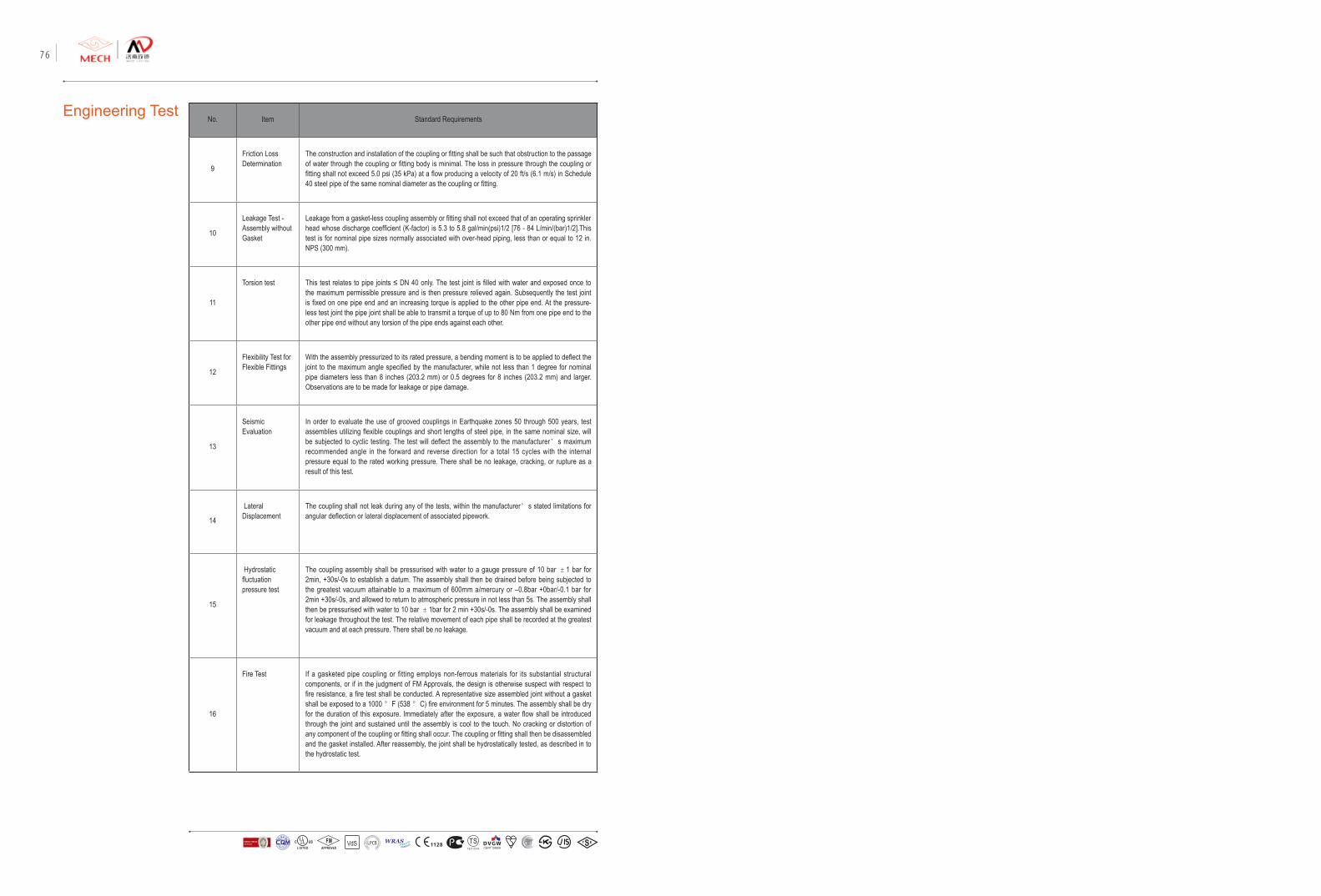
No. Item Standard Requirements
9
Friction Loss Determination
The construction and installation of the coupling or fitting shall be such that obstruction to the passage of water through the coupling or fitting body is minimal. The loss in pressure through the coupling or fitting shall not exceed 5.0 psi (35 kPa) at a flow producing a velocity of 20 ft/s (6.1 m/s) in Schedule 40 steel pipe of the same nominal diameter as the coupling or fitting.
10
Leakage Test - Assembly without Gasket
Leakage from a gasket-less coupling assembly or fitting shall not exceed that of an operating sprinkler head whose discharge coefficient (K-factor) is 5.3 to 5.8 gal/min(psi)1/2 [76 - 84 L/min/(bar)1/2].This test is for nominal pipe sizes normally associated with over-head piping, less than or equal to 12 in. NPS (300 mm).
11
Torsion test This test relates to pipe joints ≤ DN 40 only. The test joint is filled with water and exposed once to the maximum permissible pressure and is then pressure relieved again. Subsequently the test joint is fixed on one pipe end and an increasing torque is applied to the other pipe end. At the pressure-less test joint the pipe joint shall be able to transmit a torque of up to 80 Nm from one pipe end to the other pipe end without any torsion of the pipe ends against each other.
12
Flexibility Test for Flexible Fittings
With the assembly pressurized to its rated pressure, a bending moment is to be applied to deflect the joint to the maximum angle specified by the manufacturer, while not less than 1 degree for nominal pipe diameters less than 8 inches (203.2 mm) or 0.5 degrees for 8 inches (203.2 mm) and larger. Observations are to be made for leakage or pipe damage.
13
Seismic Evaluation
In order to evaluate the use of grooved couplings in Earthquake zones 50 through 500 years, test assemblies utilizing flexible couplings and short lengths of steel pipe, in the same nominal size, will be subjected to cyclic testing. The test will deflect the assembly to the manufacturer’s maximum recommended angle in the forward and reverse direction for a total 15 cycles with the internal pressure equal to the rated working pressure. There shall be no leakage, cracking, or rupture as a result of this test.
14
Lateral Displacement
The coupling shall not leak during any of the tests, within the manufacturer’s stated limitations for angular deflection or lateral displacement of associated pipework.
15
Hydrostatic fluctuation pressure test
The coupling assembly shall be pressurised with water to a gauge pressure of 10 bar ±1 bar for 2min, +30s/-0s to establish a datum. The assembly shall then be drained before being subjected to the greatest vacuum attainable to a maximum of 600mm a/mercury or –0.8bar +0bar/-0.1 bar for 2min +30s/-0s, and allowed to return to atmospheric pressure in not less than 5s. The assembly shall then be pressurised with water to 10 bar ±1bar for 2 min +30s/-0s. The assembly shall be examined for leakage throughout the test. The relative movement of each pipe shall be recorded at the greatest vacuum and at each pressure. There shall be no leakage.
16
Fire Test If a gasketed pipe coupling or fitting employs non-ferrous materials for its substantial structural components, or if in the judgment of FM Approvals, the design is otherwise suspect with respect to fire resistance, a fire test shall be conducted. A representative size assembled joint without a gasket shall be exposed to a 1000 °F (538 °C) fire environment for 5 minutes. The assembly shall be dry for the duration of this exposure. Immediately after the exposure, a water flow shall be introduced through the joint and sustained until the assembly is cool to the touch. No cracking or distortion of any component of the coupling or fitting shall occur. The coupling or fitting shall then be disassembled and the gasket installed. After reassembly, the joint shall be hydrostatically tested, as described in to the hydrostatic test.
Engineering Test
VdS 1128 T STS2710Y44
WRASA P P R O V E D
P R O D U C TFM
APPROVED LOSS P
REVE
NTION CERTIFICATIO
N BO
ARD
CERTIF ICATIO
N
方
圆认证
BUREAU VERITASVdS 1128 T STS2710Y44
WRASA P P R O V E D
P R O D U C TFM
APPROVED LOSS P
REVE
NTION CERTIFICATIO
N BO
ARD
CERTIF ICATIO
N
方
圆认证
BUREAU VERITAS
Ductile Iron Grooved Fittings and Couplings 7776


