Download - Diaphragm Pump General Brochure
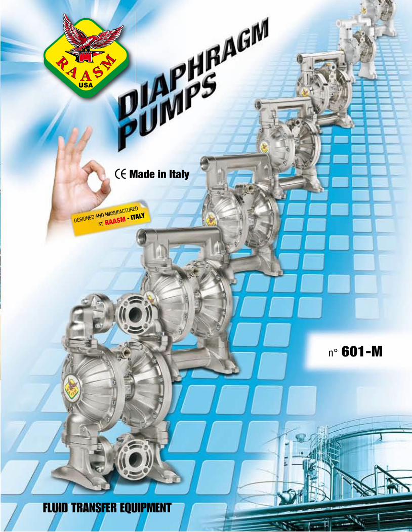
FLUID TRANSFER EQUIPMENT
Made in Italy
DESIGNED AND MANUFACTURED
AT RAASM - ITALY
n° 601-M
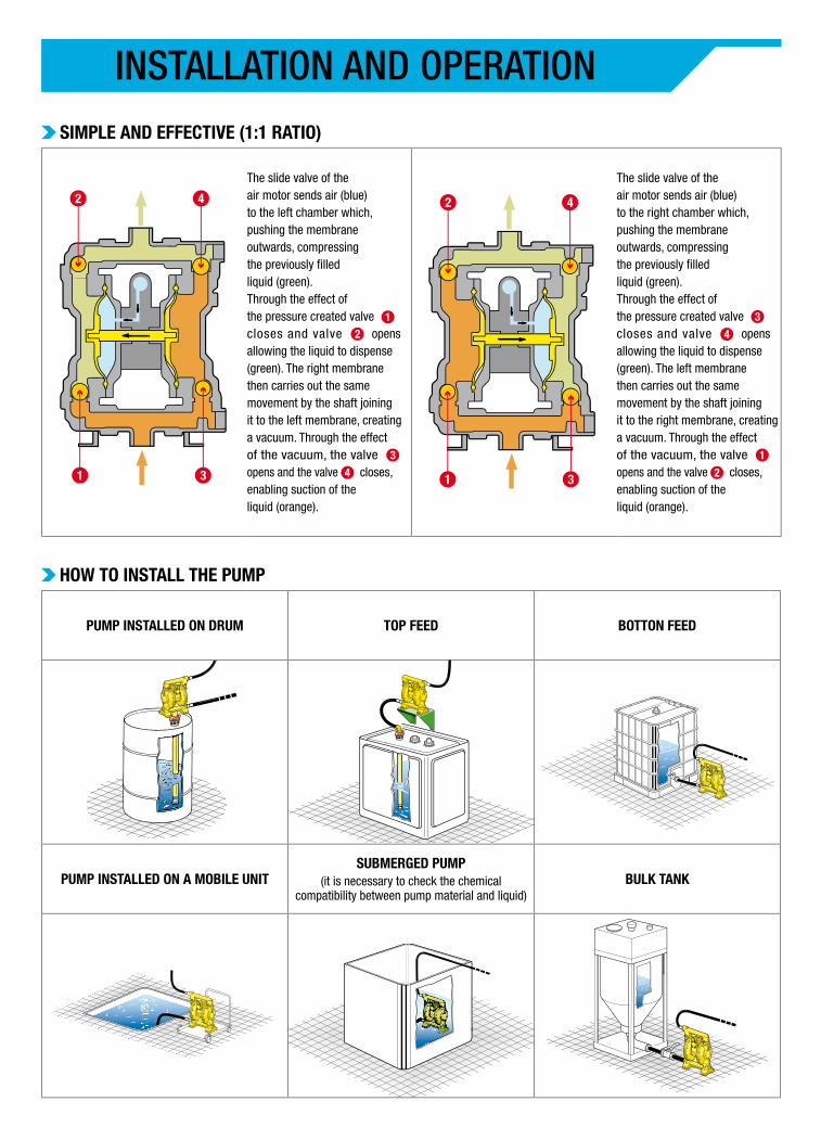
PUMP INSTALLED ON DRUM TOP FEED BOTTON FEED
PUMP INSTALLED ON A MOBILE UNITSUBMERGED PUMP
(it is necessary to check the chemical compatibility between pump material and liquid)
BULK TANK
HOW TO INSTALL THE PUMP
SIMPLE AND EFFECTIVE (1:1 RATIO)
INSTALLATION AND OPERATION
The slide valve of the air motor sends air (blue) to the left chamber which, pushing the membrane outwards, compressing the previously filled liquid (green). Through the effect of the pressure created valve closes and valve opens allowing the liquid to dispense(green). The right membrane then carries out the same movement by the shaft joining it to the left membrane, creating a vacuum. Through the effect of the vacuum, the valve opens and the valve closes, enabling suction of the liquid (orange).
The slide valve of the air motor sends air (blue) to the right chamber which, pushing the membrane outwards, compressing the previously filled liquid (green). Through the effect of the pressure created valve closes and valve opens allowing the liquid to dispense(green). The left membrane then carries out the same movement by the shaft joining it to the right membrane, creating a vacuum. Through the effect of the vacuum, the valve opens and the valve closes, enabling suction of the liquid (orange).
2 4
1 3 1 3
42
12
3
4
3
4
1
2
MATERIALS AND ATEX VERSIONS
MANIFOLD FOR INLET AND OUTLET
FLOWINSIDE
DIAMETER
KIND OF MATERIALS
MOTOR INNERFLANGES
PARTS IN CONTACT WITH
THE FLUIDMEMBRANE BALLS SEATS
2B = plastic for Zone 2 A/ = NPT threaded connection 16 = 1/2” 1= nichel plat. aluminium
1= nichel plat. aluminium
1 = nichel plated aluminium
E = EPDM A = acetalic A = acetalic3C = aluminium for Zone 1 C/ = mult. NPT threaded con. 26 = 1” H = hytrel H = hytrel H = hytrel
D/ = connection with flange 30 = 1.1/4” 7 = polypropylene N = NBR S = santoprene P = polypropyleneF/ = multiple modular connection with flange
40 = 1.1/2” S = santoprene T = PTFE S = santoprene50 = 2” T = PTFE +
hytrel1 = cylindrical
acetalicG/ = dual inlet connection with flange 2 = cylindrical
polypropyleneH/ = dual inlet NPT threaded connection
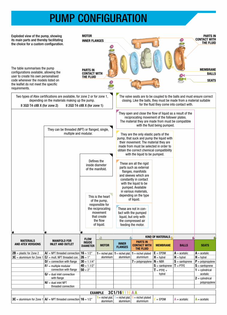
EXAMPLE 3C1/16111E A A3C = aluminium for Zone 1 A/ = NPT threaded connection 16 = 1/2” 1= nichel plat.
aluminium1= nichel plat.
aluminium1 = nichel plated
aluminium E = EPDM A = acetalic A = acetalic
INNER FLANGESMOTOR
MEMBRANE
PARTS IN CONTACT WITH
THE FLUID
BALLS
SEATS
PARTS IN CONTACT WITH THE FLUID
They are the only elastic parts of the pump, that suck and pump the liquid with
their movement. The material they are made from must be selected in order to obtain the correct chemical compatibility
with the liquid to be pumped.
These are all the rigid parts such as external
flanges, manifolds and sleeves which are constantly in contact with the liquid to be pumped. Available
in various materials, depending on the type
of liquid.
These are not in con-tact with the pumped liquid, but only with the compressed air feeding the motor.
They open and close the flow of liquid as a result of the reciprocating movement of the follower plates.
The material they are made from must be compatible with the fluid being pumped.
Defines the inside diameterof the manifold.
Two types of Atex certifications are available, for zone 2 or for zone 1, depending on the materials making up the pump.
II 3GD T4 cIIB X (for zone 2) II 2GD T4 cIIB X (for zone 1)
This is the heart of the pump,
responsible for the reciprocating
movementthat create
the flow of liquid.
They can be threaded (NPT) or flanged, single, multiple and modular.
The valve seats are to be coupled to the balls and must ensure correct closing. Like the balls, they must be made from a material suitable
for the fluid they come into contact with.
PUMP CONFIGURATION
The table summarises the pump configurations available, allowing the user to create his own personalised code whenever the models listed on the leaflet do not meet the specific requirements.
Exploded view of the pump, showing its main parts and thereby facilitating the choice for a custom configuration.
*
**
Balls for inlet and outlet
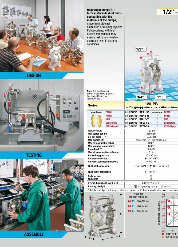
8 bar (116 psi)
4 bar (58 psi)
6 bar (87 psi)
SAE30 oil: (ISO VG 100) 68 °FKIND OF FLUID: Water 68 °F
75 150 225 3008
(116)
6(87)
4(58)
0l/min 45 90 135 180
1,6(56)
0,8(28)
0,4(14)
bar(psi)
cycles/min m3/min(cfm)
FLUI
D OU
TLET
PRE
SSUR
E
AIR
CONS
UMPT
ION
0
gpm (12) (24) (36) (48)
A
B
C
A
B
C
1,2(42)
2(29)
105 210 315 4208
(116)
6(87)
4(58)
0l/min 20 40 60 80
0,65(23)
0,49(17.2)
0,32(11.5)
bar(psi)
cycles/min m3/min(cfm)
FLUI
D OU
TLET
PRE
SSUR
E
AIR
CONS
UMPT
ION
KIND OF FLUID: Water 68 °F
0
A
B
C
A
B
C
SAE30 oil: (ISO VG 100) 68 °F
gpm (5.4) (10.7) (16) (21)
0,16(5.75)
2(29)
SAE30 oil: (ISO VG 100) 68 °FKIND OF FLUID: Water 68 °F
75 150 225 3008
(116)
6(87)
4(58)
0l/min 45 90 135 180
1,6(56)
1,2(42)
0,8(28)
bar(psi)
cycles/min m3/min(cfm)
FLUI
D OU
TLET
PRE
SSUR
E
AIR
CONS
UMPT
ION
0
gpm (12) (24) (36) (48)
A
B
C
A
B
C
0,4(14)
2(29)
KIND OF FLUID: Water 68 °F
38 75 113 1508
(116)
6(87)
4(58)
0l/min 150 300 450 600
4(140)
3(105)
2(70)
bar(psi)
cycles/min m3/min(cfm)
FLUI
D OU
TLET
PRE
SSUR
E
AIR
CONS
UMPT
ION
0
gpm (40) (80) (120) (160)
A
B
C
A
B
C
1(35)
2(29)
A A
BB
CC
PUMP AIR FEEDING PRESSURE
SAE30 oil: (ISO VG 100) 68 °F
85 170 255 3408
(116)
6(87)
4(58)
0l/min 15 30 45 60
0,53(19)
0,4(14.2)
0,13(4.7)
bar(psi)
cycles/min m3/min(cfm)
FLUI
D OU
TLET
PRE
SSUR
E
AIR
CONS
UMPT
ION
0
A
B
C
A
B
C
gpm (4) (8) (12) (16)
KIND OF FLUID: Water 68 °F
0,27(9.5)
2(29)
65 130 195 2608
(116)
6(87)
4(58)
0l/min 50 100 150 200
1,35(48)
0,9(32)
0,45(16)
bar(psi)
cycles/min m3/min(cfm)
FLUI
D OU
TLET
PRE
SSUR
E
AIR
CONS
UMPT
ION
0
gpm (13) (26) (40) (52)
A
B
C
A
B
C
SAE30 oil: (ISO VG 100) 68 °FKIND OF FLUID: Water 68 °F
1,8(64)
2(29)
55 110 165 2208
(116)
6(87)
4(58)
0l/min 120 240 360 480
3,4(120)
2,55(90)
1,7(60)
bar(psi)
cycles/min m3/min(cfm)
FLUI
D OU
TLET
PRE
SSUR
E
AIR
CONS
UMPT
ION
0
gpm (32) (64) (96) (128)
A
B
C
A
B
C
KIND OF FLUID: Water 68 °F
0,85(30)
2(29)
38 75 113 1508
(116)
6(87)
4(58)
0l/min 155 310 465 620
4(140)
3(105)
1(35)
bar(psi)
cycles/min m3/min(cfm)
FLUI
D OU
TLET
PRE
SSUR
E
AIR
CONS
UMPT
ION
0
gpm (41.5) (83) (125) (166)
A
B
C
A
B
C
KIND OF FLUID: Water 68 °F
2(70)
2(29)
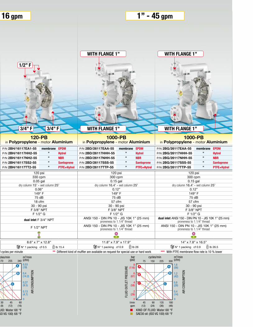
Series 120-PBin Polypropylene - motor Aluminium
120-PBin Polypropylene - motor Aluminium
1000-PBin Polypropylene - motor Aluminium
1000-PBin Polypropylene - motor Aluminium
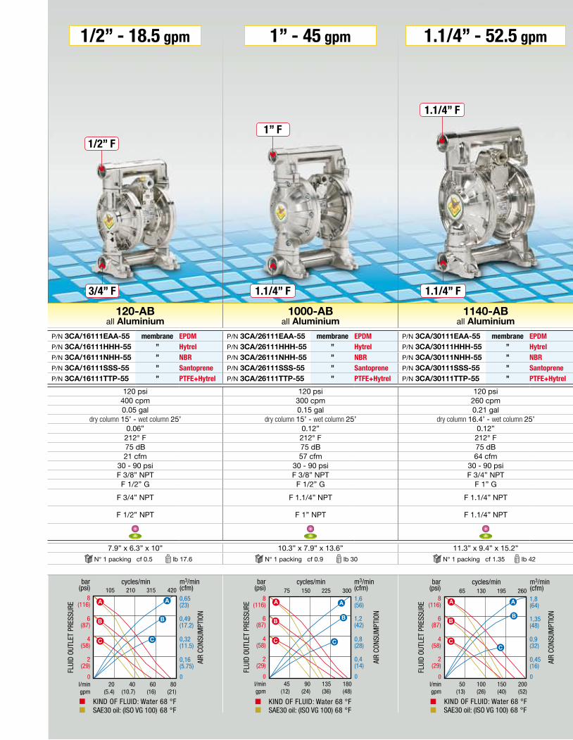
120-ABall Aluminium
1000-ABall Aluminium
1140-ABall Aluminium
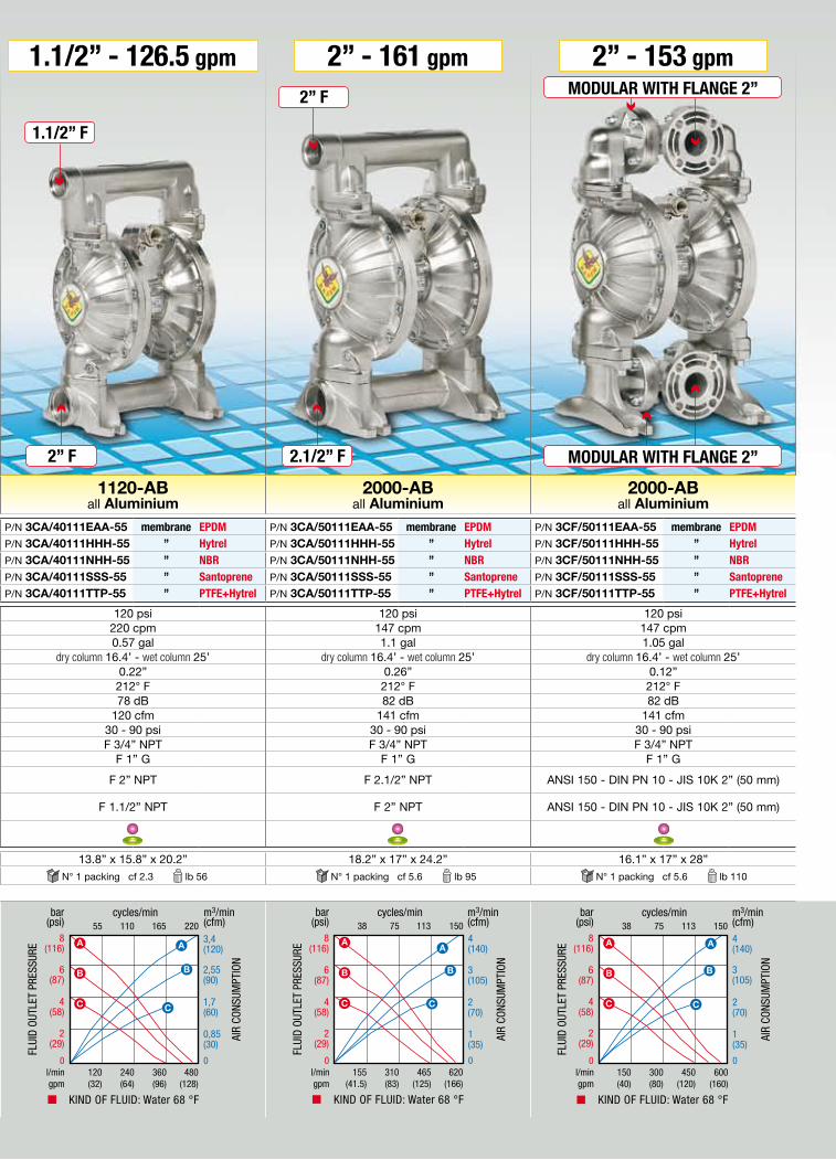
1120-ABall Aluminium
2000-ABall Aluminium
2000-ABall Aluminium
membrane EPDM P/N 2BC/16117EA1-55 membrane EPDM P/N 2BH/16117EA1-55 membrane EPDM P/N 2BD/26117EAA-55 membrane EPDM P/N 2BG/26117EAA-55 membrane EPDM P/N 3CA/16111EAA-55 membrane EPDM P/N 3CA/26111EAA-55 membrane EPDM P/N 3CA/30111EAA-55 membrane EPDM P/N 3CA/40111EAA-55 membrane EPDM P/N 3CA/50111EAA-55 membrane EPDM P/N 3CF/50111EAA-55 membrane EPDMHytrel P/N 2BC/16117HH2-55 ” Hytrel P/N 2BH/16117HH2-55 ” Hytrel P/N 2BD/26117HHH-55 ” Hytrel P/N 2BG/26117HHH-55 ” Hytrel P/N 3CA/16111HHH-55 ” Hytrel P/N 3CA/26111HHH-55 ” Hytrel P/N 3CA/30111HHH-55 ” Hytrel P/N 3CA/40111HHH-55 ” Hytrel P/N 3CA/50111HHH-55 ” Hytrel P/N 3CF/50111HHH-55 ” HytrelNBR P/N 2BC/16117NH2-55 ” NBR P/N 2BH/16117NH2-55 ” NBR P/N 2BD/26117NHH-55 ” NBR P/N 2BG/26117NHH-55 ” NBR P/N 3CA/16111NHH-55 ” NBR P/N 3CA/26111NHH-55 ” NBR P/N 3CA/30111NHH-55 ” NBR P/N 3CA/40111NHH-55 ” NBR P/N 3CA/50111NHH-55 ” NBR P/N 3CF/50111NHH-55 ” NBRSantoprene P/N 2BC/16117SS2-55 ” Santoprene P/N 2BH/16117SS2-55 ” Santoprene P/N 2BD/26117SSS-55 ” Santoprene P/N 2BG/26117SSS-55 ” Santoprene P/N 3CA/16111SSS-55 ” Santoprene P/N 3CA/26111SSS-55 ” Santoprene P/N 3CA/30111SSS-55 ” Santoprene P/N 3CA/40111SSS-55 ” Santoprene P/N 3CA/50111SSS-55 ” Santoprene P/N 3CF/50111SSS-55 ” SantoprenePTFE+Hytrel *** P/N 2BC/16117TT2-55 ” PTFE+Hytrel P/N 2BH/16117TT2-55 ” PTFE+Hytrel P/N 2BD/26117TTP-55 ” PTFE+Hytrel P/N 2BG/26117TTP-55 ” PTFE+Hytrel P/N 3CA/16111TTP-55 ” PTFE+Hytrel P/N 3CA/26111TTP-55 ” PTFE+Hytrel P/N 3CA/30111TTP-55 ” PTFE+Hytrel P/N 3CA/40111TTP-55 ” PTFE+Hytrel P/N 3CA/50111TTP-55 ” PTFE+Hytrel P/N 3CF/50111TTP-55 ” PTFE+Hytrel
Max. pressure 120 psi 120 psi 120 psi 120 psi 120 psi 120 psi 120 psi 120 psi 120 psi 120 psiMax cycles per min 330 cpm 330 cpm 300 cpm 300 cpm 400 cpm 300 cpm 260 cpm 220 cpm 147 cpm 147 cpmGal per cycle 0.05 gal 0.05 gal 0.15 gal 0.15 gal 0.05 gal 0.15 gal 0.21 gal 0.57 gal 1.1 gal 1.05 galMax suction lift dry column 15’ - wet column 25’ dry column 15’ - wet column 25’ dry column 16.4’ - wet column 25’ dry column 16.4’ - wet column 25’ dry column 15’ - wet column 25’ dry column 15’ - wet column 25’ dry column 16.4’ - wet column 25’ dry column 16.4’ - wet column 25’ dry column 16.4’ - wet column 25’ dry column 16.4’ - wet column 25’Max size pumpable solids 0.06” 0.06” 0.12” 0.12” 0.06” 0.12” 0.12” 0.22” 0.26” 0.12”Max working temperature 149° F 149° F 149° F 149° F 212° F 212° F 212° F 212° F 212° F 212° FNoise level 75 dB 75 dB 75 dB 75 dB 75 dB 75 dB 75 dB 78 dB 82 dB 82 dBMax air consumption (m3/min) 18 cfm 18 cfm 57 cfm 57 cfm 21 cfm 57 cfm 64 cfm 120 cfm 141 cfm 141 cfmAir working pressure 30 - 90 psi 30 - 90 psi 30 - 90 psi 30 - 90 psi 30 - 90 psi 30 - 90 psi 30 - 90 psi 30 - 90 psi 30 - 90 psi 30 - 90 psiAir inlet connection F 3/8” NPT F 3/8” NPT F 3/8” NPT F 3/8” NPT F 3/8” NPT F 3/8” NPT F 3/4” NPT F 3/4” NPT F 3/4” NPT F 3/4” NPTAir outlet connection (muffler) F 1/2” G F 1/2” G F 1/2” G F 1/2” G F 1/2” G F 1/2” G F 1” G F 1” G F 1” G F 1” G
Fluid inlet connection F 3/4” NPT (F 1” NPT for drum) dual inlet F 3/4” NPT ANSI 150 - DIN PN 10 - JIS 10K 1” (25 mm) proneness to 1.1/4” thread
dual inlet ANSI 150 - DIN PN 10 - JIS 10K 1” (25 mm) proneness to 1.1/4” thread F 3/4” NPT F 1.1/4” NPT F 1.1/4” NPT F 2” NPT F 2.1/2” NPT ANSI 150 - DIN PN 10 - JIS 10K 2” (50 mm)
Fluid outlet connection F 1/2” NPT F 1/2” NPT ANSI 150 - DIN PN 10 - JIS 10K 1” (25 mm) proneness to 1.1/4” thread
ANSI 150 - DIN PN 10 - JIS 10K 1” (25 mm) proneness to 1.1/4” thread F 1/2” NPT F 1” NPT F 1.1/4” NPT F 1.1/2” NPT F 2” NPT ANSI 150 - DIN PN 10 - JIS 10K 2” (50 mm)
Balls for inlet and outlet
Overall dimensions (A x B x C) 8.6” x 7” x 12.8” 8.6” x 7” x 12.8” 11.8” x 7.9” x 17.9” 14” x 7.8” x 16.5” 7.9” x 6.3” x 10” 10.3” x 7.9” x 13.6” 11.3” x 9.4” x 15.2” 13.8” x 15.8” x 20.2” 18.2” x 17” x 24.2” 16.1” x 17” x 28”Packing - Weight Displacement per cycle may be influenced by suction lift, fluid viscosity, air pressure, number of cycles per minute Different kind of muffler are available on request for special use or hard work With PTFE membrane flow rate is 10 % lower
1.1/4” F
1.1/4” F
1/2” F
3/4” F 1.1/4” F
A
C
B
1/2” - 16 gpm 1” - 45 gpm 1/2” - 18.5 gpm 1” - 45 gpm 1.1/4” - 52.5 gpm 1.1/2” - 126.5 gpm 2” - 161 gpm 2” - 153 gpm
2” F MODULAR WITH FLANGE 2”
MODULAR WITH FLANGE 2”
2.1/2” F
2” F
1.1/2” F
1” F
3/4” F
1/2” F
1” F
1/2” F
3/4” F 3/4” F WITH FLANGE 1”
WITH FLANGE 1”
N° 1 packing cf 0.5 lb 15.4 N° 1 packing cf 0.5 lb 15.4 N° 1 packing cf 0.9 lb 26 N° 1 packing cf 0.9 lb 26.5 N° 1 packing cf 0.5 lb 17.6 N° 1 packing cf 0.9 lb 30 N° 1 packing cf 1.35 lb 42 N° 1 packing cf 2.3 lb 56 N° 1 packing cf 5.6 lb 95 N° 1 packing cf 5.6 lb 110
Note: The max flow rate shown in the below graphics has been obtained by laboratory test. WITH FLANGE 1”
WITH FLANGE 1”
Diaphragm pumps R. 1:1 for transfer industrial fluids compatible with the materials of the pumps, made from die-cast aluminium or molding injected Polypropylene, with high quality components, they ensure lasting and reliable operation even in extreme conditions.
* ** ***
DESIGN
ASSEMBLY
TESTING
*
**
Balls for inlet and outlet
8 bar (116 psi)
4 bar (58 psi)
6 bar (87 psi)
SAE30 oil: (ISO VG 100) 68 °FKIND OF FLUID: Water 68 °F
75 150 225 3008
(116)
6(87)
4(58)
0l/min 45 90 135 180
1,6(56)
0,8(28)
0,4(14)
bar(psi)
cycles/min m3/min(cfm)
FLUI
D OU
TLET
PRE
SSUR
E
AIR
CONS
UMPT
ION
0
gpm (12) (24) (36) (48)
A
B
C
A
B
C
1,2(42)
2(29)
105 210 315 4208
(116)
6(87)
4(58)
0l/min 20 40 60 80
0,65(23)
0,49(17.2)
0,32(11.5)
bar(psi)
cycles/min m3/min(cfm)
FLUI
D OU
TLET
PRE
SSUR
E
AIR
CONS
UMPT
ION
KIND OF FLUID: Water 68 °F
0
A
B
C
A
B
C
SAE30 oil: (ISO VG 100) 68 °F
gpm (5.4) (10.7) (16) (21)
0,16(5.75)
2(29)
SAE30 oil: (ISO VG 100) 68 °FKIND OF FLUID: Water 68 °F
75 150 225 3008
(116)
6(87)
4(58)
0l/min 45 90 135 180
1,6(56)
1,2(42)
0,8(28)
bar(psi)
cycles/min m3/min(cfm)
FLUI
D OU
TLET
PRE
SSUR
E
AIR
CONS
UMPT
ION
0
gpm (12) (24) (36) (48)
A
B
C
A
B
C
0,4(14)
2(29)
KIND OF FLUID: Water 68 °F
38 75 113 1508
(116)
6(87)
4(58)
0l/min 150 300 450 600
4(140)
3(105)
2(70)
bar(psi)
cycles/min m3/min(cfm)
FLUI
D OU
TLET
PRE
SSUR
E
AIR
CONS
UMPT
ION
0
gpm (40) (80) (120) (160)
A
B
C
A
B
C
1(35)
2(29)
A A
BB
CC
PUMP AIR FEEDING PRESSURE
SAE30 oil: (ISO VG 100) 68 °F
85 170 255 3408
(116)
6(87)
4(58)
0l/min 15 30 45 60
0,53(19)
0,4(14.2)
0,13(4.7)
bar(psi)
cycles/min m3/min(cfm)
FLUI
D OU
TLET
PRE
SSUR
E
AIR
CONS
UMPT
ION
0
A
B
C
A
B
C
gpm (4) (8) (12) (16)
KIND OF FLUID: Water 68 °F
0,27(9.5)
2(29)
65 130 195 2608
(116)
6(87)
4(58)
0l/min 50 100 150 200
1,35(48)
0,9(32)
0,45(16)
bar(psi)
cycles/min m3/min(cfm)
FLUI
D OU
TLET
PRE
SSUR
E
AIR
CONS
UMPT
ION
0
gpm (13) (26) (40) (52)
A
B
C
A
B
C
SAE30 oil: (ISO VG 100) 68 °FKIND OF FLUID: Water 68 °F
1,8(64)
2(29)
55 110 165 2208
(116)
6(87)
4(58)
0l/min 120 240 360 480
3,4(120)
2,55(90)
1,7(60)
bar(psi)
cycles/min m3/min(cfm)
FLUI
D OU
TLET
PRE
SSUR
E
AIR
CONS
UMPT
ION
0
gpm (32) (64) (96) (128)
A
B
C
A
B
C
KIND OF FLUID: Water 68 °F
0,85(30)
2(29)
38 75 113 1508
(116)
6(87)
4(58)
0l/min 155 310 465 620
4(140)
3(105)
1(35)
bar(psi)
cycles/min m3/min(cfm)
FLUI
D OU
TLET
PRE
SSUR
E
AIR
CONS
UMPT
ION
0
gpm (41.5) (83) (125) (166)
A
B
C
A
B
C
KIND OF FLUID: Water 68 °F
2(70)
2(29)
Series 120-PBin Polypropylene - motor Aluminium
120-PBin Polypropylene - motor Aluminium
1000-PBin Polypropylene - motor Aluminium
1000-PBin Polypropylene - motor Aluminium
120-ABall Aluminium
1000-ABall Aluminium
1140-ABall Aluminium
1120-ABall Aluminium
2000-ABall Aluminium
2000-ABall Aluminium
membrane EPDM P/N 2BC/16117EA1-55 membrane EPDM P/N 2BH/16117EA1-55 membrane EPDM P/N 2BD/26117EAA-55 membrane EPDM P/N 2BG/26117EAA-55 membrane EPDM P/N 3CA/16111EAA-55 membrane EPDM P/N 3CA/26111EAA-55 membrane EPDM P/N 3CA/30111EAA-55 membrane EPDM P/N 3CA/40111EAA-55 membrane EPDM P/N 3CA/50111EAA-55 membrane EPDM P/N 3CF/50111EAA-55 membrane EPDMHytrel P/N 2BC/16117HH2-55 ” Hytrel P/N 2BH/16117HH2-55 ” Hytrel P/N 2BD/26117HHH-55 ” Hytrel P/N 2BG/26117HHH-55 ” Hytrel P/N 3CA/16111HHH-55 ” Hytrel P/N 3CA/26111HHH-55 ” Hytrel P/N 3CA/30111HHH-55 ” Hytrel P/N 3CA/40111HHH-55 ” Hytrel P/N 3CA/50111HHH-55 ” Hytrel P/N 3CF/50111HHH-55 ” HytrelNBR P/N 2BC/16117NH2-55 ” NBR P/N 2BH/16117NH2-55 ” NBR P/N 2BD/26117NHH-55 ” NBR P/N 2BG/26117NHH-55 ” NBR P/N 3CA/16111NHH-55 ” NBR P/N 3CA/26111NHH-55 ” NBR P/N 3CA/30111NHH-55 ” NBR P/N 3CA/40111NHH-55 ” NBR P/N 3CA/50111NHH-55 ” NBR P/N 3CF/50111NHH-55 ” NBRSantoprene P/N 2BC/16117SS2-55 ” Santoprene P/N 2BH/16117SS2-55 ” Santoprene P/N 2BD/26117SSS-55 ” Santoprene P/N 2BG/26117SSS-55 ” Santoprene P/N 3CA/16111SSS-55 ” Santoprene P/N 3CA/26111SSS-55 ” Santoprene P/N 3CA/30111SSS-55 ” Santoprene P/N 3CA/40111SSS-55 ” Santoprene P/N 3CA/50111SSS-55 ” Santoprene P/N 3CF/50111SSS-55 ” SantoprenePTFE+Hytrel *** P/N 2BC/16117TT2-55 ” PTFE+Hytrel P/N 2BH/16117TT2-55 ” PTFE+Hytrel P/N 2BD/26117TTP-55 ” PTFE+Hytrel P/N 2BG/26117TTP-55 ” PTFE+Hytrel P/N 3CA/16111TTP-55 ” PTFE+Hytrel P/N 3CA/26111TTP-55 ” PTFE+Hytrel P/N 3CA/30111TTP-55 ” PTFE+Hytrel P/N 3CA/40111TTP-55 ” PTFE+Hytrel P/N 3CA/50111TTP-55 ” PTFE+Hytrel P/N 3CF/50111TTP-55 ” PTFE+Hytrel
Max. pressure 120 psi 120 psi 120 psi 120 psi 120 psi 120 psi 120 psi 120 psi 120 psi 120 psiMax cycles per min 330 cpm 330 cpm 300 cpm 300 cpm 400 cpm 300 cpm 260 cpm 220 cpm 147 cpm 147 cpmGal per cycle 0.05 gal 0.05 gal 0.15 gal 0.15 gal 0.05 gal 0.15 gal 0.21 gal 0.57 gal 1.1 gal 1.05 galMax suction lift dry column 15’ - wet column 25’ dry column 15’ - wet column 25’ dry column 16.4’ - wet column 25’ dry column 16.4’ - wet column 25’ dry column 15’ - wet column 25’ dry column 15’ - wet column 25’ dry column 16.4’ - wet column 25’ dry column 16.4’ - wet column 25’ dry column 16.4’ - wet column 25’ dry column 16.4’ - wet column 25’Max size pumpable solids 0.06” 0.06” 0.12” 0.12” 0.06” 0.12” 0.12” 0.22” 0.26” 0.12”Max working temperature 149° F 149° F 149° F 149° F 212° F 212° F 212° F 212° F 212° F 212° FNoise level 75 dB 75 dB 75 dB 75 dB 75 dB 75 dB 75 dB 78 dB 82 dB 82 dBMax air consumption (m3/min) 18 cfm 18 cfm 57 cfm 57 cfm 21 cfm 57 cfm 64 cfm 120 cfm 141 cfm 141 cfmAir working pressure 30 - 90 psi 30 - 90 psi 30 - 90 psi 30 - 90 psi 30 - 90 psi 30 - 90 psi 30 - 90 psi 30 - 90 psi 30 - 90 psi 30 - 90 psiAir inlet connection F 3/8” NPT F 3/8” NPT F 3/8” NPT F 3/8” NPT F 3/8” NPT F 3/8” NPT F 3/4” NPT F 3/4” NPT F 3/4” NPT F 3/4” NPTAir outlet connection (muffler) F 1/2” G F 1/2” G F 1/2” G F 1/2” G F 1/2” G F 1/2” G F 1” G F 1” G F 1” G F 1” G
Fluid inlet connection F 3/4” NPT (F 1” NPT for drum) dual inlet F 3/4” NPT ANSI 150 - DIN PN 10 - JIS 10K 1” (25 mm) proneness to 1.1/4” thread
dual inlet ANSI 150 - DIN PN 10 - JIS 10K 1” (25 mm) proneness to 1.1/4” thread F 3/4” NPT F 1.1/4” NPT F 1.1/4” NPT F 2” NPT F 2.1/2” NPT ANSI 150 - DIN PN 10 - JIS 10K 2” (50 mm)
Fluid outlet connection F 1/2” NPT F 1/2” NPT ANSI 150 - DIN PN 10 - JIS 10K 1” (25 mm) proneness to 1.1/4” thread
ANSI 150 - DIN PN 10 - JIS 10K 1” (25 mm) proneness to 1.1/4” thread F 1/2” NPT F 1” NPT F 1.1/4” NPT F 1.1/2” NPT F 2” NPT ANSI 150 - DIN PN 10 - JIS 10K 2” (50 mm)
Balls for inlet and outlet
Overall dimensions (A x B x C) 8.6” x 7” x 12.8” 8.6” x 7” x 12.8” 11.8” x 7.9” x 17.9” 14” x 7.8” x 16.5” 7.9” x 6.3” x 10” 10.3” x 7.9” x 13.6” 11.3” x 9.4” x 15.2” 13.8” x 15.8” x 20.2” 18.2” x 17” x 24.2” 16.1” x 17” x 28”Packing - Weight Displacement per cycle may be influenced by suction lift, fluid viscosity, air pressure, number of cycles per minute Different kind of muffler are available on request for special use or hard work With PTFE membrane flow rate is 10 % lower
1.1/4” F
1.1/4” F
1/2” F
3/4” F 1.1/4” F
A
C
B
1/2” - 16 gpm 1” - 45 gpm 1/2” - 18.5 gpm 1” - 45 gpm 1.1/4” - 52.5 gpm 1.1/2” - 126.5 gpm 2” - 161 gpm 2” - 153 gpm
2” F MODULAR WITH FLANGE 2”
MODULAR WITH FLANGE 2”
2.1/2” F
2” F
1.1/2” F
1” F
3/4” F
1/2” F
1” F
1/2” F
3/4” F 3/4” F WITH FLANGE 1”
WITH FLANGE 1”
N° 1 packing cf 0.5 lb 15.4 N° 1 packing cf 0.5 lb 15.4 N° 1 packing cf 0.9 lb 26 N° 1 packing cf 0.9 lb 26.5 N° 1 packing cf 0.5 lb 17.6 N° 1 packing cf 0.9 lb 30 N° 1 packing cf 1.35 lb 42 N° 1 packing cf 2.3 lb 56 N° 1 packing cf 5.6 lb 95 N° 1 packing cf 5.6 lb 110
Note: The max flow rate shown in the below graphics has been obtained by laboratory test. WITH FLANGE 1”
WITH FLANGE 1”
Diaphragm pumps R. 1:1 for transfer industrial fluids compatible with the materials of the pumps, made from die-cast aluminium or molding injected Polypropylene, with high quality components, they ensure lasting and reliable operation even in extreme conditions.
* ** ***
DESIGN
ASSEMBLY
TESTING
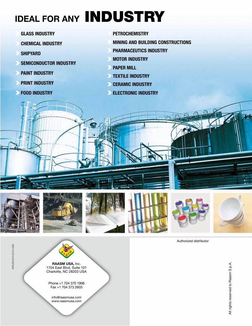
Authorized distributor
All
rig
hts
rese
rved
to
Raa
sm S
.p.A
.
Phone +1 704 370 1906Fax +1 704 373 2603
RAASM USA, Inc.1704 East Blvd, Suite 101Charlotte, NC 28203 USA
IDEAL FOR ANY INDUSTRYGLASS INDUSTRY
CHEMICAL INDUSTRY
SHIPYARD
SEMICONDUCTOR INDUSTRY
PAINT INDUSTRY
PRINT INDUSTRY
FOOD INDUSTRY
PETROCHEMISTRY
MINING AND BUILDING CONSTRUCTIONS
PHARMACEUTICS INDUSTRY
MOTOR INDUSTRY
PAPER MILL
TEXTILE INDUSTRY
CERAMIC INDUSTRY
ELECTRONIC INDUSTRY
WR
UD
A/D
.P.2
010-
US
A


