Download - Cu-Ni Pipes, Flanges & Fittings
This is the html version of the file http://www.marine-applications.com/assets/user/files/.svn/text-base/offshore_productrange.pdf. Google automatically generates html versions of documents as we crawl the web.
Page 1
KME German
y A
G & Co. K
G
OSN
A®
10[GB]
Copper-Nickel Seawater Piping Systems
Offshore product range:
Pipes, fittings and flanges of OSNA®10
Page 1 of 67Copper-Nickel Seawater Piping Systems Offshore product range: Pipes, fittings and fl...
04-Oct-12http://webcache.googleusercontent.com/search?hl=en-IN&q=cache:dHUuS8mYuFAJ:...
Page 2
1
2
3
4
5
6
8
9
10
12
13
14
17
Contents
Your Partner KME
The Material
Offshore Product Range
Design Scope
KME Quality-Management
Pipes
Elbows
Equal Tees
Reducing Tees
Caps
Reducers
Saddle Pieces
Composite Weld Neck Flanges
Page 2 of 67Copper-Nickel Seawater Piping Systems Offshore product range: Pipes, fittings and fl...
04-Oct-12http://webcache.googleusercontent.com/search?hl=en-IN&q=cache:dHUuS8mYuFAJ:...
17
19
20
22
23
24
44
Composite Weld Neck Flanges
Composite Slip-On Flanges
Solid Weld Neck Flanges
Solid Slip-On Flanges
Composite Blind Flanges
Capillary Brazing, Socket Weld Fittings
and Miscellaneous
Appendix
Page 3 of 67Copper-Nickel Seawater Piping Systems Offshore product range: Pipes, fittings and fl...
04-Oct-12http://webcache.googleusercontent.com/search?hl=en-IN&q=cache:dHUuS8mYuFAJ:...
Page 3
Your Partner - KME
The Expert in Seawater Piping
Marine Applications
KME’s division Marine Applications specializes in
the production and supply of copper-nickel alloys
for seawater piping system. Since decades, these
alloys have successfully used in:
• Merchant and military shipbuilding
• Offshore oil and gas installations
• Coastal petroleum and petrochemical
processing plants
• Seawater desalination plants
Hundred years of experience, a thorough understanding of
the different industries’ specific problems, a potent range of
application-oriented products and services, plus qualified
technical advice and assistance, have been the bedrock of
KME’s relations with its customers.
Copper-nickel alloys are widely applied in:
• Seawater cooling systems
• Fire water systems
• Sanitary systems
• Deck steam pipes
• Deluge systems
• Hydraulic and pneumatic systems
• Seawater feed lines to desalination and
processing units
• Splash zone sheathing
Page 4 of 67Copper-Nickel Seawater Piping Systems Offshore product range: Pipes, fittings and fl...
04-Oct-12http://webcache.googleusercontent.com/search?hl=en-IN&q=cache:dHUuS8mYuFAJ:...
KME Germany AG & Co. KG — OSNA®10
• Seawater desalination plants
• Coastal electricity generation plants
• Splash zone sheathing
Page 4
Main Advantages of OSNA
Despite the rough conditions in marine service
and the highly corrosive nature of seawater, the
products provide well balanced combination of
technical and economical advantages:
• Simple alloying system with good weldability
• Excellent ductility and toughness
• Outstanding erosion corrosion performance
• Resistant to uniform and localised corrosion
• No effect of ambient seawater temperatures
• No effect of seawater chlorination
• Resistant to biofouling
• Resistant to stress
• Low maintenance costs
• A lot of design experience
KME OSNA®10-Alloy
The chemical composition of the KME’s OSNA®10-
alloy is modified to ensure the compliance with all
international specifications. Controlled content of
alloying elements and minimised concentration of
impurities ensure reliable service and fabrication
properties of the alloy.
The Material
Page 5 of 67Copper-Nickel Seawater Piping Systems Offshore product range: Pipes, fittings and fl...
04-Oct-12http://webcache.googleusercontent.com/search?hl=en-IN&q=cache:dHUuS8mYuFAJ:...
2
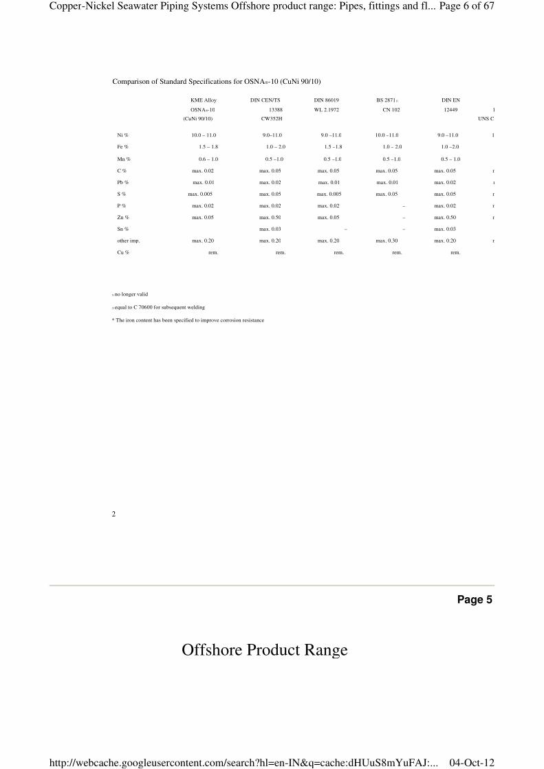
KME Alloy
OSNA®-10
(CuNi 90/10)
DIN CEN/TS
13388
CW352H
DIN 86019
WL 2.1972
BS 28711)
CN 102
DIN EN
12449 144
UNS C 7060 x
Ni % 10.0 – 11.0 9.0–11.0 9.0 –11.0 10.0 –11.0 9.0 –11.0 10.0
Fe % 1.5 – 1.8 1.0 – 2.0 1.5 –1.8 1.0 – 2.0 1.0 –2.0
Mn % 0.6 – 1.0 0.5 –1.0 0.5 –1.0 0.5 –1.0 0.5 – 1.0
C % max. 0.02 max. 0.05 max. 0.05 max. 0.05 max. 0.05 max. 0.05
Pb % max. 0.01 max. 0.02 max. 0.01 max. 0.01 max. 0.02 max. 0.01
S % max. 0.005 max. 0.05 max. 0.005 max. 0.05 max. 0.05 max. 0.02
P % max. 0.02 max. 0.02 max. 0.02 – max. 0.02 max. 0.02
Zn % max. 0.05 max. 0.50 max. 0.05 – max. 0.50 max. 0.20
Sn % max. 0.03 – – max. 0.03
other imp. max. 0.20 max. 0.20 max. 0.20 max. 0.30 max. 0.20 max. 0.30
Cu % rem. rem. rem. rem. rem.
1) no longer valid
2) equal to C 70600 for subsequent welding
* The iron content has been specified to improve corrosion resistance
Comparison of Standard Specifications for OSNA®-10 (CuNi 90/10)
Page 5
Offshore Product Range
The OSNA 10 offshore product range is based on:
Page 6 of 67Copper-Nickel Seawater Piping Systems Offshore product range: Pipes, fittings and fl...
04-Oct-12http://webcache.googleusercontent.com/search?hl=en-IN&q=cache:dHUuS8mYuFAJ:...
The OSNA®10 offshore product range is based on:
• EEMUA –144: 1987 Tubes1 Seamless and Welded
• EEMUA –145: 1987 Flanges Composite and Solid
• EEMUA –146: 1987 Fittings
The unique dimensional range from ½ inch to
36 inch ensures the supply of the entire piping
systems from one source. Although the pipe
dimensions of 38 and 40 inch are not included
in the EEMUA 144 – 1987 they are available
here as they are commonly specified in offshore
projects. Based on ASME specifications,
additional components are included.
1 The reference „pipe“ rather than „tube“ is used in this document.
Page 7 of 67Copper-Nickel Seawater Piping Systems Offshore product range: Pipes, fittings and fl...
04-Oct-12http://webcache.googleusercontent.com/search?hl=en-IN&q=cache:dHUuS8mYuFAJ:...
KME Germany AG & Co. KG — OSNA®10
Page 6
Design Scope
Working pressures and temperatures of components included
in this specification:
1. 16 bar/232 psi: -29°C/-20°F to +75°C/+167°F
2. 20 bar/290 psi: -29°C/-20°F to +38°C/+100°F
Pipes Seamless and Welded:
• Pipes are based on BS MA 60, DIN 86007, and ANSI/ASME B31.3
• The wall thicknesses comply with ANSI B31.3 and DIN 86007 as
well as International Association of Classification Societies with
additional allowances for robustness to withstand mechanical
damage, especially in the smaller sizes.
• The fit-for-purpose corrosion allowance of 0.5 mm sufficient for
entire service life of the piping installation has been included.
This corrosion allowance is in accordance with all major classi-
fication societies specified for alloys containing ≥10 wt. % Ni and
≥1.5 wt. % Fe. Mechanical properties of pipes are given in
Appendix A.
Flanges Composite and Solid:
• Included series of composite (lap type) and solid flanges in metric
dimensions based on ANSI B16.5, MSS SP-44 and BS 1560
• The basic metric dimensions for drilling and flange outside
diameters are those given in ANSI B16.5 and MSS SP 44 Class
150 rating with inch size bolting.
• The copper-nickel stub end and flange joint faces are machine
finished and comply with the corresponding Sections of EEMUA
145 and are summarized in the Appendix A.
• Mechanical properties pressure/temperature ratings of flanges
Physical Properties of CuNi 90/10
The physical properties of the alloy are given
by Appendix B. The basic allowable stresses in
tension are in
Table A-1.
Welding
The welding consumables used for the manufac
turing of welded components are in
with AWS
cedure specification and welder qualification are
in accordance
Testing of Welds
The weld seams are examined by the liquid dye
penetrant testing in
section VIII, division 1, appendix 8. The radiogra
phic examination is performed for the complete
length of each weld to meet the requirements of
ASME code, section VIII, UW51.
Gaskets
The gaskets normally used with flanges are
those made from aramid fibre with nitrile binder
in accordance
The gasket hardness shall not be less than
75 Shore. The gaskets shall not be graphited.
In order to ensure adequate seating when solid
Page 8 of 67Copper-Nickel Seawater Piping Systems Offshore product range: Pipes, fittings and fl...
04-Oct-12http://webcache.googleusercontent.com/search?hl=en-IN&q=cache:dHUuS8mYuFAJ:...
4
• Mechanical properties pressure/temperature ratings of flanges
are given in Appendix A.
Fittings:
• The specification comprises a series for pipe fittings including
butt weld, socket welding, capillary brazing, threaded, self-
reinforced fittings as well as saddle pieces.
• The “building in” dimensions of the butt welding fittings are based
on ANSI B16.9 apart from the caps that are based on DIN 28011
(with suitable amendments).
• Mechanical properties pressure/temperature ratings of fittings
are given in Appendix A.
In order to ensure adequate seating when solid
weldneck and solid slip
irrespective of gasket materials, the gaskets
shall be located within the bolt circle. Note:
Gaskets should not be used when mating with
elastomerlrubber faced flanges.
Suggested Branch Connections
Suggested branch connections are provided by
Appendix D.
PDMS Data
The components mentioned in this catalogue are
available in the PDMS
for more information.
Page 7
KME Quality-Management
Page 9 of 67Copper-Nickel Seawater Piping Systems Offshore product range: Pipes, fittings and fl...
04-Oct-12http://webcache.googleusercontent.com/search?hl=en-IN&q=cache:dHUuS8mYuFAJ:...
KME Germany AG & Co. KG — OSNA®10
Quality is the very basis of reliability – quality in every detail,
in every step of work.
For decades now, KME has been consistently putting into action
the corporate idea of quality, and, with it, gained the reputation
of being a reliable supplier throughout the world. The fulfilment of
our customers expectations as to KME products and services in
all re spects is the declared corporate policy. To assure this, KME
Quality Management System has been set up, implemented and
certified to DIN EN ISO 9001 by Lloyd’s Register Quality Assurance
at all KME locations.
KME Quality Management System comprehends process-integrated
quality controls, internal product and system audits, the systematical
training of all employees and the operating of computer aided
statistical methods.
The results of KME production give convincing proof: our results
have been surpassing the requirements of national and international
standards for years.
KME produces quality.
Page 8
Page 10 of 67Copper-Nickel Seawater Piping Systems Offshore product range: Pipes, fittings and...
04-Oct-12http://webcache.googleusercontent.com/search?hl=en-IN&q=cache:dHUuS8mYuFAJ:...
Pipes
Seamless Pipes
Seamless pipes are in accordance with
EEMUA–144, Section 1. They are manufactured
from hot extruded shells followed by cold work
and annealing.
Welded Pipes
Longitudinally welded pipes are in accordance
with EEMUA–144, Section 2. They are manufac-
tured from hot rolled or cold rolled and annealed
sheet or plates in accordance with BS 2870, BS
2875, ASTM B171 or ASTM B402. Mechanical
testing is carried out in accordance with the
standards above. The pipes are supplied in
“as welded” condition.
Dimensions
Dimensions are based on EEMUA –144,
Tables 1.2.1-1.2.2 and 2.2.1-2.2.2. However,
the pipe diameters range from ½ in./16 mm to
36 in./914 mm. Although the pipe dimensions
of 38 in./965 mm and 40 in./1016 mm are not
included in the EEMUA 144 – 1987 they are
available on request as they are commonly spe-
cified. The corresponding wall thicknesses of
the pipes comply with the pressure containment
requirements of ASME B31.3 as well as the
requirements of the International Association of
Classification Societies. Pipes with other wall
thicknesses are available on request.
Tolerances
See notes 1-4 for seamless and notes 2
welded pipes.
Weld Preparation
For wall thickness less than 3 mm, the pipes are
supplied with plain weld ends. Larger thicknesses
are supplied with the weld bevel of 37
Page 11 of 67Copper-Nickel Seawater Piping Systems Offshore product range: Pipes, fittings and...
04-Oct-12http://webcache.googleusercontent.com/search?hl=en-IN&q=cache:dHUuS8mYuFAJ:...
6
Page 9
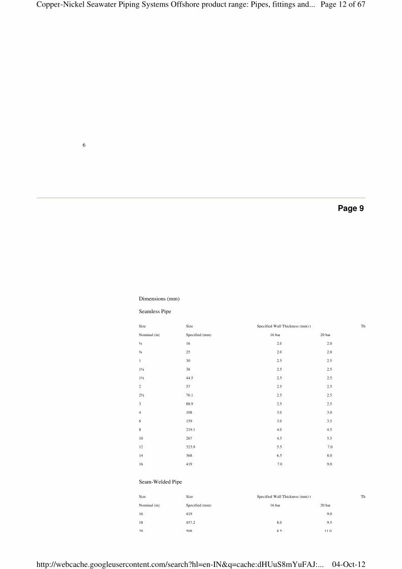
Dimensions (mm)
Seamless Pipe
Size Size Specified Wall Thickness (mm) t Theoretical Weight/Metre (kg)
Nominal (in) Specified (mm) 16 bar 20 bar
½ 16 2.0 2.0
¾ 25 2.0 2.0
1 30 2.5 2.5
1¼ 38 2.5 2.5
1½ 44.5 2.5 2.5
2 57 2.5 2.5
2½ 76.1 2.5 2.5
3 88.9 2.5 2.5
4 108 3.0 3.0
6 159 3.0 3.5
8 219.1 4.0 4.5
10 267 4.5 5.5
12 323.9 5.5 7.0
14 368 6.5 8.0
16 419 7.0 9.0
Seam-Welded Pipe
Size Size Specified Wall Thickness (mm) t Theoretical Weight/Metre (kg)
Nominal (in) Specified (mm) 16 bar 20 bar
16 419 9.0
18 457.2 8.0 9.5
20 508 8.5 11.0
Page 12 of 67Copper-Nickel Seawater Piping Systems Offshore product range: Pipes, fittings and...
04-Oct-12http://webcache.googleusercontent.com/search?hl=en-IN&q=cache:dHUuS8mYuFAJ:...
KME Germany AG & Co. KG — OSNA®10
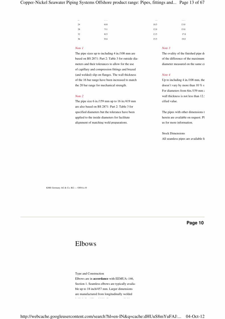
20 508 8.5 11.0
24 610 10.5 13.0
28 711 12.0 15.0
32 813 13.5 17.0
36 914 15.5 19.0
Note 1
The pipe sizes up to including 4 in./108 mm are
based on BS 2871: Part 2: Table 3 for outside dia-
meters and their tolerances to allow for the use
of capillary and compression fittings and brazed
(and welded) slip-on flanges. The wall thickness
of the 16 bar range have been increased to match
the 20 bar range for mechanical strength.
Note 2
The pipe size 6 in./159 mm up to 16 in./419 mm
are also based on BS 2871: Part 2: Table 3 for
specified diameters but the tolerance have been
applied to the inside diameters for facilitate
alignment of matching weld preparations.
Note 3
The ovality of the finished pipe doesn
of the difference of the maximum and minimum
diameter measured on the same cross section.
Note 4
Up to including 4 in./108 mm, the wall thickness
doesn’t vary by more than 10 % specified therein.
For diameters from 6in./159 mm and larger, the
wall thickness is not less than 12.5 % of the spe
cified value.
The pipes with other dimensions than mentioned
herein are available on request. Please contact
us for more information.
Stock Dimensions
All seamless pipes are available from stock.
Page 10
Elbows
Type and Construction
Elbows are in accordance with EEMUA–146,
Section 1. Seamless elbows are typically availa-
ble up to 18 inch/457 mm. Larger dimensions
are manufactured from longitudinally welded
half shells. 45° and 90° elbows are available
Page 13 of 67Copper-Nickel Seawater Piping Systems Offshore product range: Pipes, fittings and...
04-Oct-12http://webcache.googleusercontent.com/search?hl=en-IN&q=cache:dHUuS8mYuFAJ:...
8
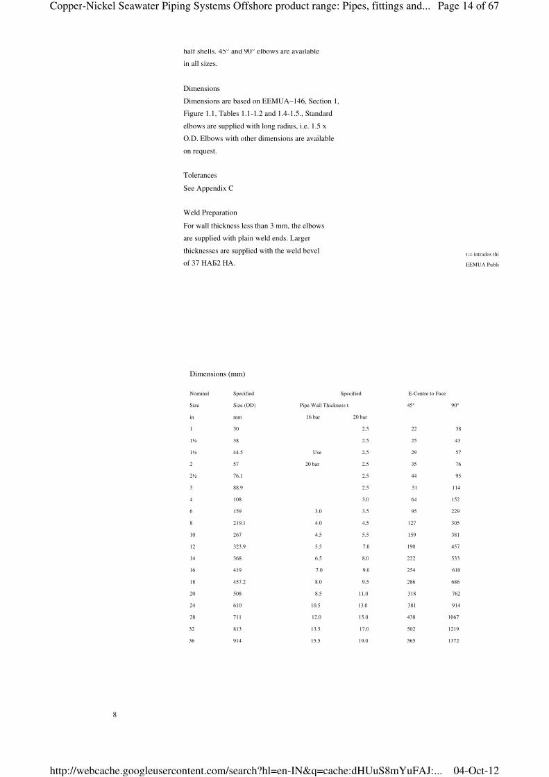
ti = intrados thickness (min) in
EEMUA Publication No. 146: Section 1, Table 1.5
Dimensions (mm)
Nominal Specified Specified E-Centre to Face
Size Size (OD) Pipe Wall Thickness t 45° 90°
in mm 16 bar 20 bar
1 30 2.5 22 38
1¼ 38 2.5 25 43
1½ 44.5 Use 2.5 29 57
2 57 20 bar 2.5 35 76
2½ 76.1 2.5 44 95
3 88.9 2.5 51 114
4 108 3.0 64 152
6 159 3.0 3.5 95 229
8 219.1 4.0 4.5 127 305
10 267 4.5 5.5 159 381
12 323.9 5.5 7.0 190 457
14 368 6.5 8.0 222 533
16 419 7.0 9.0 254 610
18 457.2 8.0 9.5 286 686
20 508 8.5 11.0 318 762
24 610 10.5 13.0 381 914
28 711 12.0 15.0 438 1067
32 813 13.5 17.0 502 1219
36 914 15.5 19.0 565 1372
half shells. 45° and 90° elbows are available
in all sizes.
Dimensions
Dimensions are based on EEMUA–146, Section 1,
Figure 1.1, Tables 1.1-1.2 and 1.4-1.5., Standard
elbows are supplied with long radius, i.e. 1.5 x
O.D. Elbows with other dimensions are available
on request.
Tolerances
See Appendix C
Weld Preparation
For wall thickness less than 3 mm, the elbows
are supplied with plain weld ends. Larger
thicknesses are supplied with the weld bevel
of 37 НАБ2 НА.
Page 14 of 67Copper-Nickel Seawater Piping Systems Offshore product range: Pipes, fittings and...
04-Oct-12http://webcache.googleusercontent.com/search?hl=en-IN&q=cache:dHUuS8mYuFAJ:...
Page 11
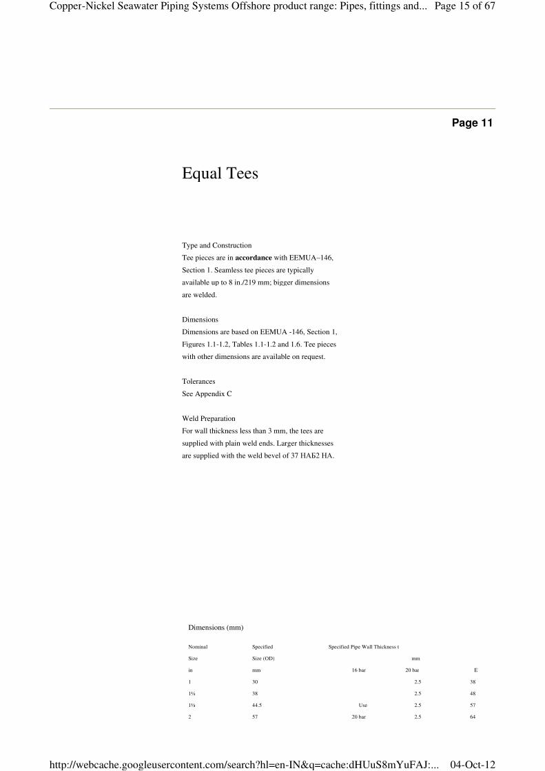
Dimensions (mm)
Nominal Specified Specified Pipe Wall Thickness t
Size Size (OD) mm
in mm 16 bar 20 bar E
1 30 2.5 38
1¼ 38 2.5 48
1½ 44.5 Use 2.5 57
2 57 20 bar 2.5 64
Type and Construction
Tee pieces are in accordance with EEMUA–146,
Section 1. Seamless tee pieces are typically
available up to 8 in./219 mm; bigger dimensions
are welded.
Dimensions
Dimensions are based on EEMUA -146, Section 1,
Figures 1.1-1.2, Tables 1.1-1.2 and 1.6. Tee pieces
with other dimensions are available on request.
Tolerances
See Appendix C
Weld Preparation
For wall thickness less than 3 mm, the tees are
supplied with plain weld ends. Larger thicknesses
are supplied with the weld bevel of 37 НАБ2 НА.
Equal Tees
Page 15 of 67Copper-Nickel Seawater Piping Systems Offshore product range: Pipes, fittings and...
04-Oct-12http://webcache.googleusercontent.com/search?hl=en-IN&q=cache:dHUuS8mYuFAJ:...
KME Germany AG & Co. KG — OSNA®10
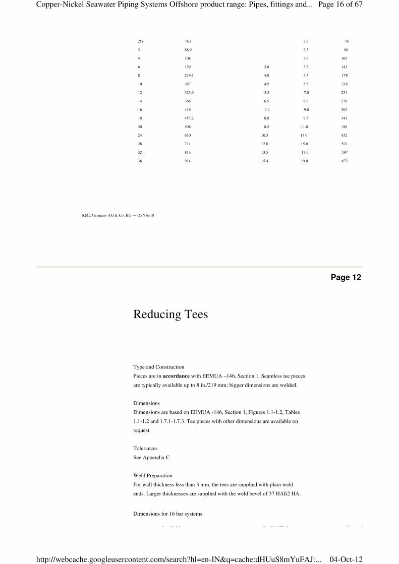
2½ 76.1 2.5 76
3 88.9 2.5 86
4 108 3.0 105
6 159 3.0 3.5 143
8 219.1 4.0 4.5 178
10 267 4.5 5.5 216
12 323.9 5.5 7.0 254
14 368 6.5 8.0 279
16 419 7.0 9.0 305
18 457.2 8.0 9.5 343
20 508 8.5 11.0 381
24 610 10.5 13.0 432
28 711 12.0 15.0 521
32 813 13.5 17.0 597
36 914 15.4 19.0 673
Page 12
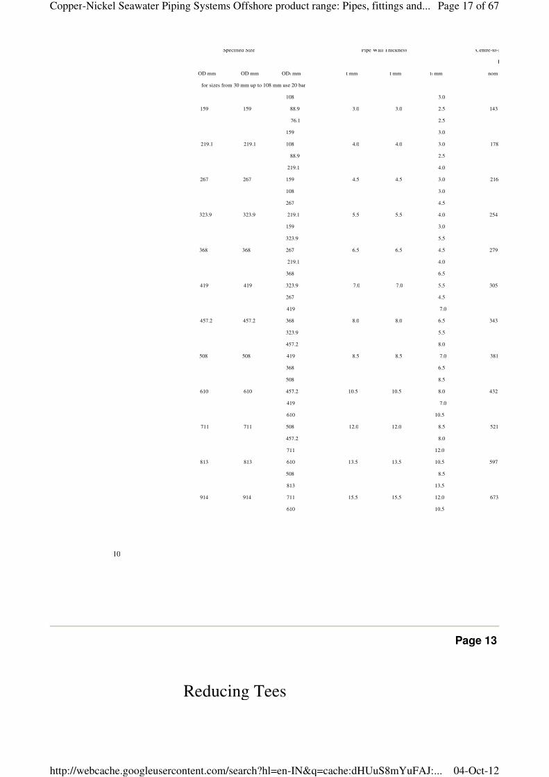
Reducing Tees
Dimensions for 16 bar systems
Specified Size Pipe Wall Thickness Centre-to-End (mm)
Type and Construction
Pieces are in accordance with EEMUA –146, Section 1. Seamless tee pieces
are typically available up to 8 in./219 mm; bigger dimensions are welded.
Dimensions
Dimensions are based on EEMUA -146, Section 1, Figures 1.1-1.2, Tables
1.1-1.2 and 1.7.1-1.7.3. Tee pieces with other dimensions are available on
request.
Tolerances
See Appendix C
Weld Preparation
For wall thickness less than 3 mm, the tees are supplied with plain weld
ends. Larger thicknesses are supplied with the weld bevel of 37 НАБ2 НА.
Page 16 of 67Copper-Nickel Seawater Piping Systems Offshore product range: Pipes, fittings and...
04-Oct-12http://webcache.googleusercontent.com/search?hl=en-IN&q=cache:dHUuS8mYuFAJ:...
10
Specified Size Pipe Wall Thickness Centre-to-End (mm)
E
OD mm OD mm OD1 mm t mm t mm t1 mm nom
for sizes from 30 mm up to 108 mm use 20 bar
108 3.0
159 159 88.9 3.0 3.0 2.5 143
76.1 2.5
159 3.0
219.1 219.1 108 4.0 4.0 3.0 178
88.9 2.5
219.1 4.0
267 267 159 4.5 4.5 3.0 216
108 3.0
267 4.5
323.9 323.9 219.1 5.5 5.5 4.0 254
159 3.0
323.9 5.5
368 368 267 6.5 6.5 4.5 279
219.1 4.0
368 6.5
419 419 323.9 7.0 7.0 5.5 305
267 4.5
419 7.0
457.2 457.2 368 8.0 8.0 6.5 343
323.9 5.5
457.2 8.0
508 508 419 8.5 8.5 7.0 381
368 6.5
508 8.5
610 610 457.2 10.5 10.5 8.0 432
419 7.0
610 10.5
711 711 508 12.0 12.0 8.5 521
457.2 8.0
711 12.0
813 813 610 13.5 13.5 10.5 597
508 8.5
813 13.5
914 914 711 15.5 15.5 12.0 673
610 10.5
Page 13
Reducing Tees
Page 17 of 67Copper-Nickel Seawater Piping Systems Offshore product range: Pipes, fittings and...
04-Oct-12http://webcache.googleusercontent.com/search?hl=en-IN&q=cache:dHUuS8mYuFAJ:...
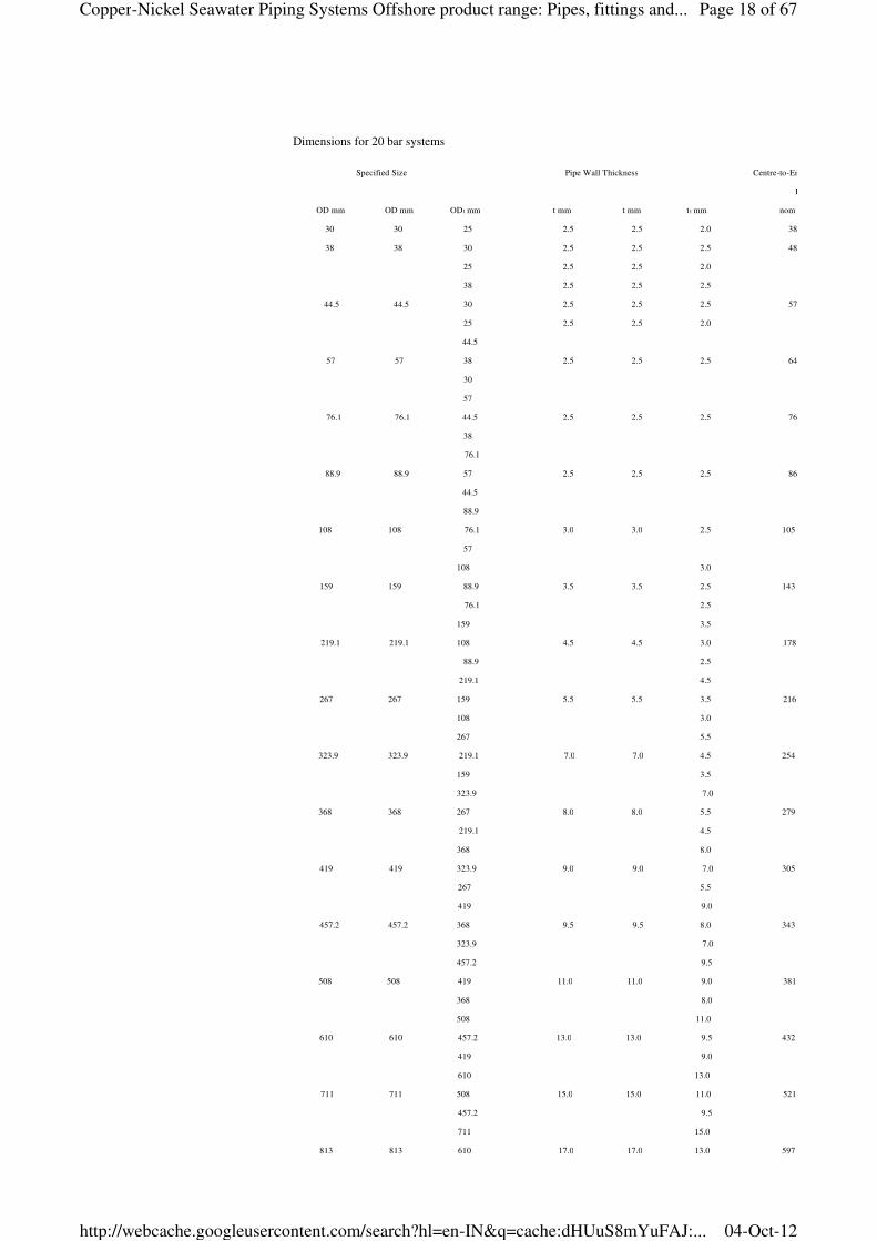
Dimensions for 20 bar systems
Specified Size Pipe Wall Thickness Centre-to-End (mm)
E
OD mm OD mm OD1 mm t mm t mm t1 mm nom
30 30 25 2.5 2.5 2.0 38
38 38 30 2.5 2.5 2.5 48
25 2.5 2.5 2.0
38 2.5 2.5 2.5
44.5 44.5 30 2.5 2.5 2.5 57
25 2.5 2.5 2.0
44.5
57 57 38 2.5 2.5 2.5 64
30
57
76.1 76.1 44.5 2.5 2.5 2.5 76
38
76.1
88.9 88.9 57 2.5 2.5 2.5 86
44.5
88.9
108 108 76.1 3.0 3.0 2.5 105
57
108 3.0
159 159 88.9 3.5 3.5 2.5 143
76.1 2.5
159 3.5
219.1 219.1 108 4.5 4.5 3.0 178
88.9 2.5
219.1 4.5
267 267 159 5.5 5.5 3.5 216
108 3.0
267 5.5
323.9 323.9 219.1 7.0 7.0 4.5 254
159 3.5
323.9 7.0
368 368 267 8.0 8.0 5.5 279
219.1 4.5
368 8.0
419 419 323.9 9.0 9.0 7.0 305
267 5.5
419 9.0
457.2 457.2 368 9.5 9.5 8.0 343
323.9 7.0
457.2 9.5
508 508 419 11.0 11.0 9.0 381
368 8.0
508 11.0
610 610 457.2 13.0 13.0 9.5 432
419 9.0
610 13.0
711 711 508 15.0 15.0 11.0 521
457.2 9.5
711 15.0
813 813 610 17.0 17.0 13.0 597
Page 18 of 67Copper-Nickel Seawater Piping Systems Offshore product range: Pipes, fittings and...
04-Oct-12http://webcache.googleusercontent.com/search?hl=en-IN&q=cache:dHUuS8mYuFAJ:...
KME Germany AG & Co. KG — OSNA®10
508 11.0
813 17.0
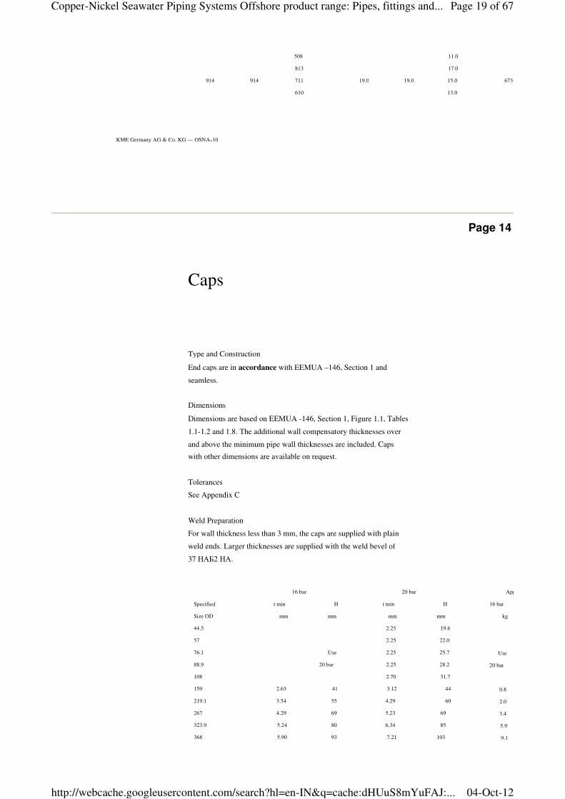
914 914 711 19.0 19.0 15.0 673
610 13.0
Page 14
Type and Construction
End caps are in accordance with EEMUA –146, Section 1 and
seamless.
Dimensions
Dimensions are based on EEMUA -146, Section 1, Figure 1.1, Tables
1.1-1.2 and 1.8. The additional wall compensatory thicknesses over
and above the minimum pipe wall thicknesses are included. Caps
with other dimensions are available on request.
Tolerances
See Appendix C
Weld Preparation
For wall thickness less than 3 mm, the caps are supplied with plain
weld ends. Larger thicknesses are supplied with the weld bevel of
37 НАБ2 НА.
Caps
16 bar 20 bar
Specified t min H t min H
Size OD mm mm mm mm
44.5 2.25 19.6
57 2.25 22.0
76.1 Use 2.25 25.7
88.9 20 bar 2.25 28.2
108 2.70 31.7
159 2.63 41 3.12 44
219.1 3.54 55 4.29 60
267 4.29 69 5.23 69
323.9 5.24 80 6.34 85
368 5.90 93 7.21 103
419 6.73 102 8.21 112
Approx. Weight
16 bar
kg
Use
20 bar
0.8
2.0
3.4
5.9
9.1
12.4
Page 19 of 67Copper-Nickel Seawater Piping Systems Offshore product range: Pipes, fittings and...
04-Oct-12http://webcache.googleusercontent.com/search?hl=en-IN&q=cache:dHUuS8mYuFAJ:...
12
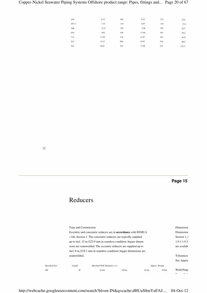
419 6.73 102 8.21 112
457.2 7.33 119 8.97 119
508 8.15 129 9.96 139
610 9.81 148 11.96 163
711 11.50 176 13.97 191
813 13.17 200 15.97 210
914 14.81 221 17.96 231
12.4
17.6
22.7
39.2
61.8
90.5
132.2
Page 15
Type and Construction
Eccentric and concentric reducers are in accordance with EEMUA
–146, Section 1. The concentric reducers are typically supplied
up to incl. 12 in./323.9 mm in seamless condition; bigger dimen-
sions are seamwelded. The eccentric reducers are supplied up to
incl. 8 in./219.1 mm in seamless condition; bigger dimensions are
seamwelded.
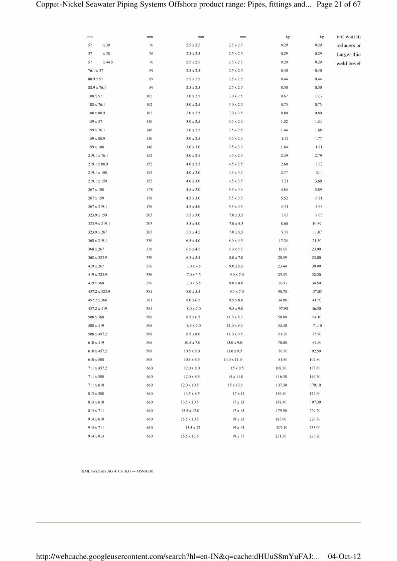
Reducers
Specified Size Length Specified Wall Thickness t x t1 Approx. Weight
OD H 16 bar 20 bar 16 bar 20 bar
mm mm mm mm kg kg
Dimensions
Dimensions are based on EEMUA
Section 1, Figures 1.1, Tables 1.1
1.9.1-1.9.3. Reducers with other dimensions
are available on request.
Tolerances
See Appendix C
Weld Preparation
For wall thickness less than 3 mm, the
Page 20 of 67Copper-Nickel Seawater Piping Systems Offshore product range: Pipes, fittings and...
04-Oct-12http://webcache.googleusercontent.com/search?hl=en-IN&q=cache:dHUuS8mYuFAJ:...
KME Germany AG & Co. KG — OSNA®10
mm mm mm mm kg kg
57 x 30 76 2.5 x 2.5 2.5 x 2.5 0.29 0.29
57 x 38 76 2.5 x 2.5 2.5 x 2.5 0.29 0.29
57 x 44.5 76 2.5 x 2.5 2.5 x 2.5 0.29 0.29
76.1 x 57 89 2.5 x 2.5 2.5 x 2.5 0.40 0.40
88.9 x 57 89 2.5 x 2.5 2.5 x 2.5 0.44 0.44
88.9 x 76.1 89 2.5 x 2.5 2.5 x 2.5 0.50 0.50
108 x 57 102 3.0 x 2.5 3.0 x 2.5 0.67 0.67
108 x 76.1 102 3.0 x 2.5 3.0 x 2.5 0.75 0.75
108 x 88.9 102 3.0 x 2.5 3.0 x 2.5 0.80 0.80
159 x 57 140 3.0 x 2.5 3.5 x 2.5 1.32 1.54
159 x 76.1 140 3.0 x 2.5 3.5 x 2.5 1.44 1.68
159 x 88.9 140 3.0 x 2.5 3.5 x 2.5 1.52 1.77
159 x 108 140 3.0 x 3.0 3.5 x 3.0 1.64 1.91
219.1 x 76.1 152 4.0 x 2.5 4.5 x 2.5 2.49 2.79
219.1 x 88.9 152 4.0 x 2.5 4.5 x 2.5 2.60 2.92
219.1 x 10⁸ 152 4.0 x 3.0 4.5 x 3.0 2.77 3.11
219.1 x 159 152 4.0 x 3.0 4.5 x 3.5 3.21 3.60
267 x 108 178 4.5 x 3.0 5.5 x 3.0 4.84 5.89
267 x 159 178 4.5 x 3.0 5.5 x 3.5 5.52 6.71
267 x 219.1 178 4.5 x 4.0 5.5 x 4.5 6.31 7.68
323.9 x 159 203 5.5 x 3.0 7.0 x 3.5 7.63 9.65
323.9 x 219.1 203 5.5 x 4.0 7.0 x 4.5 8.60 10.89
323.9 x 267 203 5.5 x 4.5 7.0 x 5.5 9.38 11.87
368 x 219.1 330 6.5 x 4.0 8.0 x 4.5 17.24 21.50
368 x 267 330 6.5 x 4.5 8.0 x 5.5 18.68 23.00
368 x 323.9 330 6.5 x 5.5 8.0 x 7.0 20.39 25.00
419 x 267 356 7.0 x 4.5 9.0 x 5.5 23.44 30.00
419 x 323.9 356 7.0 x 5.5 9.0 x 7.0 25.43 32.50
419 x 368 356 7.0 x 6.5 9.0 x 8.0 26.97 34.50
457.2 x 323.9 381 8.0 x 5.5 9.5 x 7.0 30.70 37.03
457.2 x 368 381 8.0 x 6.5 9.5 x 8.0 34.06 41.50
457.2 x 419 381 8.0 x 7.0 9.5 x 9.0 37.90 46.50
508 x 368 508 8.5 x 6.5 11.0 x 8.0 50.80 64.10
508 x 419 508 8.5 x 7.0 11.0 x 9.0 55.40 71.10
508 x 457.2 508 8.5 x 8.0 11.0 x 9.5 61.20 75.70
610 x 419 508 10.5 x 7.0 13.0 x 9.0 70.00 87.50
610 x 457.2 508 10.5 x 8.0 13.0 x 9.5 76.30 92.50
610 x 508 508 10.5 x 8.5 13.0 x 11.0 81.80 102.80
711 x 457.2 610 12.0 x 8.0 15 x 9.5 109.30 133.60
711 x 508 610 12.0 x 8.5 15 x 11.0 116.30 146.70
711 x 610 610 12.0 x 10.5 15 x 13.0 137.30 170.10
813 x 508 610 13.5 x 8.5 17 x 11 136.40 172.60
813 x 610 610 13.5 x 10.5 17 x 13 158.40 197.30
813 x 711 610 13.5 x 12.0 17 x 15 179.50 224.20
914 x 610 610 15.5 x 10.5 19 x 13 185.00 226.70
914 x 711 610 15.5 x 12 19 x 15 207.10 255.00
914 x 813 610 15.5 x 13.5 19 x 17 231.30 285.80
For wall thickness less than 3 mm, the
reducers are supplied with plain weld ends.
Larger thicknesses are supplied with the
weld bevel of 37
Page 21 of 67Copper-Nickel Seawater Piping Systems Offshore product range: Pipes, fittings and...
04-Oct-12http://webcache.googleusercontent.com/search?hl=en-IN&q=cache:dHUuS8mYuFAJ:...
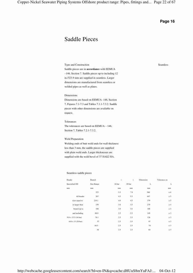
Page 16
Type and Construction
Saddle pieces are in accordance with EEMUA
–146, Section 7. Saddle pieces up to including 12
in./323.9 mm are supplied in seamless. Larger
dimensions are manufactured from seamless or
welded pipes as well as plates.
Dimensions
Dimensions are based on EEMUA -146, Section
7, Figures 7.1-7.3 and Tables 7.1.1-7.3.2. Saddle
pieces with other dimensions are available on
request.
Tolerances
The tolerances are based on EEMUA – 146,
Section 7, Tables 7.2.1-7.3.2.
Weld Preparation
Welding ends of butt weld ends for wall thickness
less than 3 mm, the saddle pieces are supplied
with plain weld ends. Larger thicknesses are
supplied with the weld bevel of 37 НАБ2 НА.
Saddle Pieces
Seamless
Seamless saddle pieces
Header Branch t t Dimension Tolerance on
Speciefied OD Size Range 16 bar 20 bar L L
mm mm mm mm mm mm
323 5.5 7.0 560 ± 6
All header 267 4.5 5.5 447 ± 5
sizes equal to 219.1 4.0 4.5 379 ± 5
or larger than 159 3.0 3.5 279 ± 4
branch up to 108 3.0 3.0 188 ± 4
and including 88.9 2.5 2.5 149 ± 3
914 x 15.5 (16 bar) 76.1 2.5 2.5 126 ± 3
610 x 13 (20 bar) 57 2.5 2.5 97 ± 3
44.5 2.5 2.5 74 ± 3
38 2.5 2.5 64 ± 3
Page 22 of 67Copper-Nickel Seawater Piping Systems Offshore product range: Pipes, fittings and...
04-Oct-12http://webcache.googleusercontent.com/search?hl=en-IN&q=cache:dHUuS8mYuFAJ:...
14
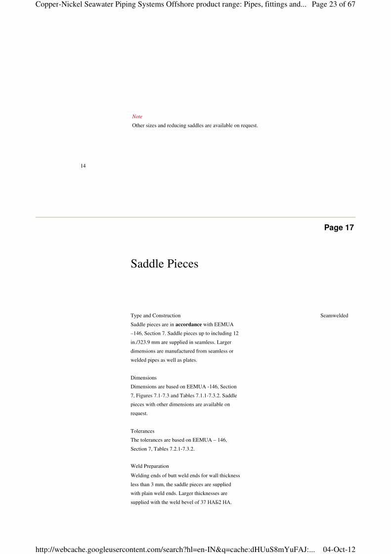
Note
Other sizes and reducing saddles are available on request.
Page 17
Type and Construction
Saddle pieces are in accordance with EEMUA
–146, Section 7. Saddle pieces up to including 12
in./323.9 mm are supplied in seamless. Larger
dimensions are manufactured from seamless or
welded pipes as well as plates.
Dimensions
Dimensions are based on EEMUA -146, Section
7, Figures 7.1-7.3 and Tables 7.1.1-7.3.2. Saddle
pieces with other dimensions are available on
request.
Tolerances
The tolerances are based on EEMUA – 146,
Section 7, Tables 7.2.1-7.3.2.
Weld Preparation
Welding ends of butt weld ends for wall thickness
less than 3 mm, the saddle pieces are supplied
with plain weld ends. Larger thicknesses are
supplied with the weld bevel of 37 НАБ2 НА.
Saddle Pieces
Seamwelded
Page 23 of 67Copper-Nickel Seawater Piping Systems Offshore product range: Pipes, fittings and...
04-Oct-12http://webcache.googleusercontent.com/search?hl=en-IN&q=cache:dHUuS8mYuFAJ:...
KME Germany AG & Co. KG — OSNA®10
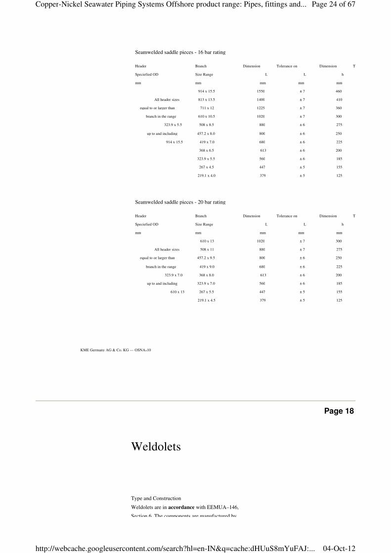
Seamwelded saddle pieces - 16 bar rating
Header Branch Dimension Tolerance on Dimension Tolerance on
Speciefied OD Size Range L L h
mm mm mm mm mm
914 x 15.5 1550 ± 7 460
All header sizes 813 x 13.5 1400 ± 7 410
equal to or larger than 711 x 12 1225 ± 7 360
branch in the range 610 x 10.5 1020 ± 7 300
323.9 x 5.5 508 x 8.5 880 ± 6 275
up to and including 457.2 x 8.0 800 ± 6 250
914 x 15.5 419 x 7.0 680 ± 6 225
368 x 6.5 613 ± 6 200
323.9 x 5.5 560 ± 6 185
267 x 4.5 447 ± 5 155
219.1 x 4.0 379 ± 5 125
Seamwelded saddle pieces - 20 bar rating
Header Branch Dimension Tolerance on Dimension Tolerance on
Speciefied OD Size Range L L h
mm mm mm mm mm
610 x 13 1020 ± 7 300
All header sizes 508 x 11 880 ± 7 275
equal to or larger than 457.2 x 9.5 800 ± 6 250
branch in the range 419 x 9.0 680 ± 6 225
323.9 x 7.0 368 x 8.0 613 ± 6 200
up to and including 323.9 x 7.0 560 ± 6 185
610 x 13 267 x 5.5 447 ± 5 155
219.1 x 4.5 379 ± 5 125
Page 18
Weldolets
Type and Construction
Weldolets are in accordance with EEMUA–146,
Section 6. The components are manufactured by
Page 24 of 67Copper-Nickel Seawater Piping Systems Offshore product range: Pipes, fittings and...
04-Oct-12http://webcache.googleusercontent.com/search?hl=en-IN&q=cache:dHUuS8mYuFAJ:...
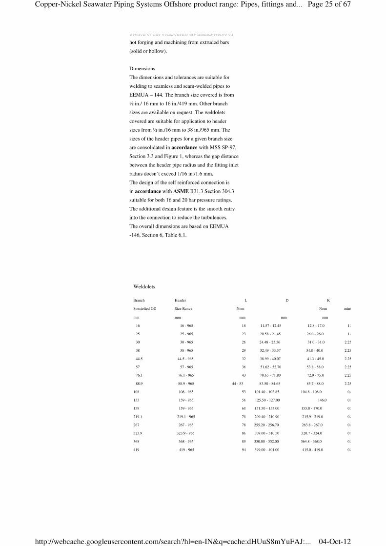
Weldolets
Branch Header L D K
Speciefied OD Size Range Nom Nom min/max
mm mm mm mm mm
16 16 - 965 18 11.57 - 12.45 12.8 - 17.0 1.8
25 25 - 965 23 20.58 - 21.45 26.0 - 26.0 1.8
30 30 - 965 26 24.48 - 25.56 31.0 - 31.0 2.25
38 38 - 965 29 32.49 - 33.57 34.8 - 40.0 2.25
44.5 44.5 - 965 32 38.99 - 40.07 41.3 - 45.0 2.25
57 57 - 965 36 51.62 - 52.70 53.8 - 58.0 2.25
76.1 76.1 - 965 43 70.65 - 71.80 72.9 - 75.0 2.25
88.9 88.9 - 965 44 - 53 83.50 - 84.65 85.7 - 88.0 2.25
108 108 - 965 53 101.40 - 102.85 104.8 - 108.0 0.8
133 159 - 965 56 125.50 - 127.00 146.0 0.8
159 159 - 965 60 151.50 - 153.00 155.8 - 170.0 0.8
219.1 219.1 - 965 70 209.40 - 210.90 215.9 - 219.0 0.8
267 267 - 965 78 255.20 - 256.70 263.8 - 267.0 0.8
323.9 323.9 - 965 86 309.00 - 310.50 320.7 - 324.0 0.8
368 368 - 965 89 350.00 - 352.00 364.8 - 368.0 0.8
419 419 - 965 94 399.00 - 401.00 415.0 - 419.0 0.8
Section 6. The components are manufactured by
hot forging and machining from extruded bars
(solid or hollow).
Dimensions
The dimensions and tolerances are suitable for
welding to seamless and seam-welded pipes to
EEMUA – 144. The branch size covered is from
½ in./ 16 mm to 16 in./419 mm. Other branch
sizes are available on request. The weldolets
covered are suitable for application to header
sizes from ½ in./16 mm to 38 in./965 mm. The
sizes of the header pipes for a given branch size
are consolidated in accordance with MSS SP-97,
Section 3.3 and Figure 1, whereas the gap distance
between the header pipe radius and the fitting inlet
radius doesn’t exceed 1/16 in./1.6 mm.
The design of the self reinforced connection is
in accordance with ASME B31.3 Section 304.3
suitable for both 16 and 20 bar pressure ratings.
The additional design feature is the smooth entry
into the connection to reduce the turbulences.
The overall dimensions are based on EEMUA
-146, Section 6, Table 6.1.
Page 25 of 67Copper-Nickel Seawater Piping Systems Offshore product range: Pipes, fittings and...
04-Oct-12http://webcache.googleusercontent.com/search?hl=en-IN&q=cache:dHUuS8mYuFAJ:...
16
Page 19
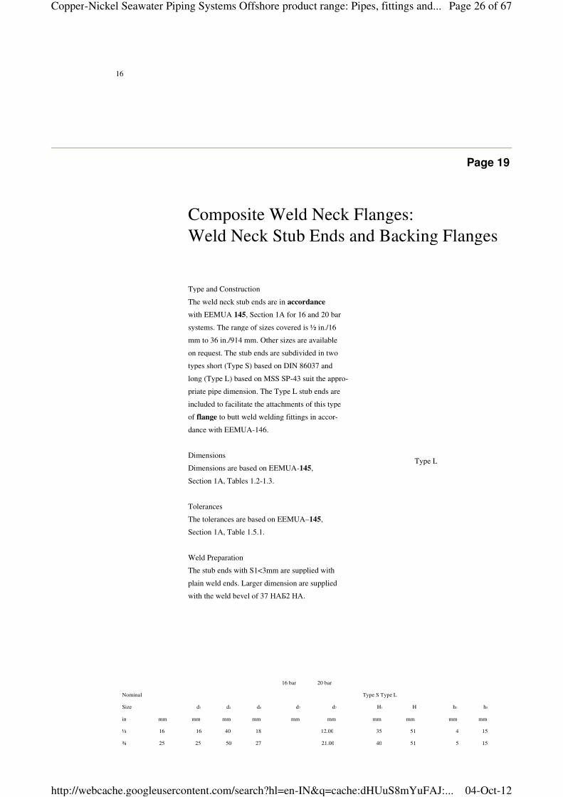
16 bar 20 bar
Nominal Type S Type L
Size d3 d4 d6 d7 d7 H1 H h2 h5
in mm mm mm mm mm mm mm mm mm mm
½ 16 16 40 18 12.00 35 51 4 15
¾ 25 25 50 27 21.00 40 51 5 15
Type and Construction
The weld neck stub ends are in accordance
with EEMUA 145, Section 1A for 16 and 20 bar
systems. The range of sizes covered is ½ in./16
mm to 36 in./914 mm. Other sizes are available
on request. The stub ends are subdivided in two
types short (Type S) based on DIN 86037 and
long (Type L) based on MSS SP-43 suit the appro-
priate pipe dimension. The Type L stub ends are
included to facilitate the attachments of this type
of flange to butt weld welding fittings in accor-
dance with EEMUA-146.
Dimensions
Dimensions are based on EEMUA-145,
Section 1A, Tables 1.2-1.3.
Tolerances
The tolerances are based on EEMUA–145,
Section 1A, Table 1.5.1.
Weld Preparation
The stub ends with S1<3mm are supplied with
plain weld ends. Larger dimension are supplied
with the weld bevel of 37 НАБ2 НА.
Composite Weld Neck Flanges:
Weld Neck Stub Ends and Backing Flanges
Type L
Page 26 of 67Copper-Nickel Seawater Piping Systems Offshore product range: Pipes, fittings and...
04-Oct-12http://webcache.googleusercontent.com/search?hl=en-IN&q=cache:dHUuS8mYuFAJ:...
KME Germany AG & Co. KG — OSNA®10
¾ 25 25 50 27 21.00 40 51 5 15
1 30 30 60 32 25.00 40 51 5 15
1¼ 38 38 70 40 Use 33.03 40 51 5 15
1½ 44.5 44.5 80 46.5 20 bar 39.53 45 51 6 15
2 57 57 99 59 52.16 45 64 6 15
2½ 76.1 76.1 120 78 71.23 45 64 6 15
3 88.9 88.9 130 91 84.08 50 64 7 15
4 108 108 158 110 102.13 50 76 7 15
6 159 159 212 161.5 153.75 152.38 50 89 9 15
8 219.1 219.1 270 222 211.10 210.10 50 102 9 15
10 267 267 320 270 257.97 255.93 50 127 9 15
12 323.9 323.9 370 327 312.83 309.74 50 152 11 16
14 368 368 430 371 354.22 351.00 50 152 11 16
16 419 419 482 422 404.17 399.84 50 152 12 16
18 457.2 457.2 530 460 441.50 438.50 50 152 12 16
20 508 508 585 511 490.50 486.50 50 152 12 20
24 610 610 685 613 589.50 584.50 60 152 14 20
28 711 711 800 719 687.50 681.50 60 190 19 24
32 813 813 905 821 786.50 779.50 60 190 20.5 24
36 914 914 1000 922 883.50 876.50 60 190 22 32
Page 20
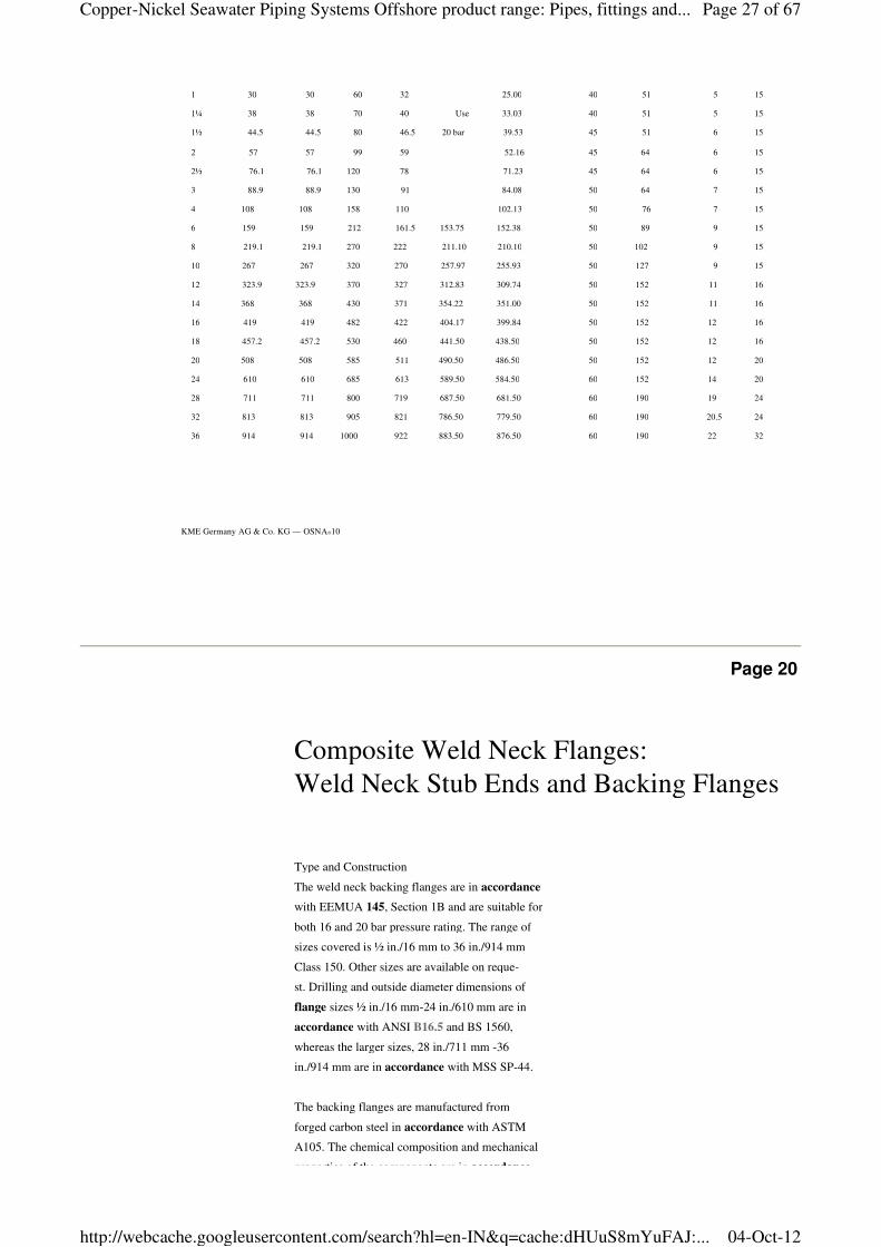
Type and Construction
The weld neck backing flanges are in accordance
with EEMUA 145, Section 1B and are suitable for
both 16 and 20 bar pressure rating. The range of
sizes covered is ½ in./16 mm to 36 in./914 mm
Class 150. Other sizes are available on reque-
st. Drilling and outside diameter dimensions of
flange sizes ½ in./16 mm-24 in./610 mm are in
accordance with ANSI B16.5 and BS 1560,
whereas the larger sizes, 28 in./711 mm -36
in./914 mm are in accordance with MSS SP-44.
The backing flanges are manufactured from
forged carbon steel in accordance with ASTM
A105. The chemical composition and mechanical
properties of the components are in accordance
Composite Weld Neck Flanges:
Weld Neck Stub Ends and Backing Flanges
Page 27 of 67Copper-Nickel Seawater Piping Systems Offshore product range: Pipes, fittings and...
04-Oct-12http://webcache.googleusercontent.com/search?hl=en-IN&q=cache:dHUuS8mYuFAJ:...
18
properties of the components are in accordance
with EEMUA 145, Section 1B, Table 1.6.2. The
recommended bolting is in accordance with
ASTM A193-B7. Unless otherwise specified the
flanges are protected by hot dipped galvanising.
Additional organic coatings such as polyamide
epoxy are available on request.
Dimensions
Dimensions are based on EEMUA -145,
Section 1B, Table 1.4.
Tolerances
The tolerances are based on EEMUA – 145,
Section 1B, Table 1.5.2.
Nominal b
Size D min. d5 K No. of e
in mm mm mm in mm mm mm Bolts mm
½ 16 89 14 5/8 15.9 19 60.3 4 2
¾ 25 98 14 5/8 15.9 28 69.8 4 3
1 30 108 14 5/8 15.9 33 79.4 4 3
1¼ 38 117 14 5/8 15.9 41 88.9 4 3
1½ 44.5 127 14 5/8 15.9 48 98.4 4 3 As for 20 bar
2 57 152 18 3/4 19.0 62 120.6 4 3
2½ 76.1 178 18 3/4 19.0 81 139.7 4 3
3 88.9 190 19 3/4 19.0 94 152.4 4 3
4 108 229 24 3/4 19.0 113 190.5 8 3
6 159 279 27 7/8 22.2 164 241.3 8 4
8 219.1 343 31 7/8 22.2 225 298.4 8 5
10 267 406 38 1 25.4 273 362.0 12 5
12 323.9 483 41 1 25.4 330 431.8 12 7
14 368 533 45 11/8 28.6 374 476.2 12 7
16 419 597 51 11/8 28.6 426 539.8 16 7
18 457.2 635 52 11/4 31.8 465 577.8 16 7
20 508 698 58 11/4 31.8 517 635.0 20 7
24 610 813 71 13/8 34.9 618 749.3 20 9 131.4
28 711 927 81 13/8 34.9 727 864.0 28 9 180.3
32 813 1060 95 15/8 41.1 829 978.0 28 9 269.0
36 914 1168 105 15/8 41.1 931 1086.0 32 9 335.8
d2
Page 21
Composite Slip-On Flanges:
Page 28 of 67Copper-Nickel Seawater Piping Systems Offshore product range: Pipes, fittings and...
04-Oct-12http://webcache.googleusercontent.com/search?hl=en-IN&q=cache:dHUuS8mYuFAJ:...
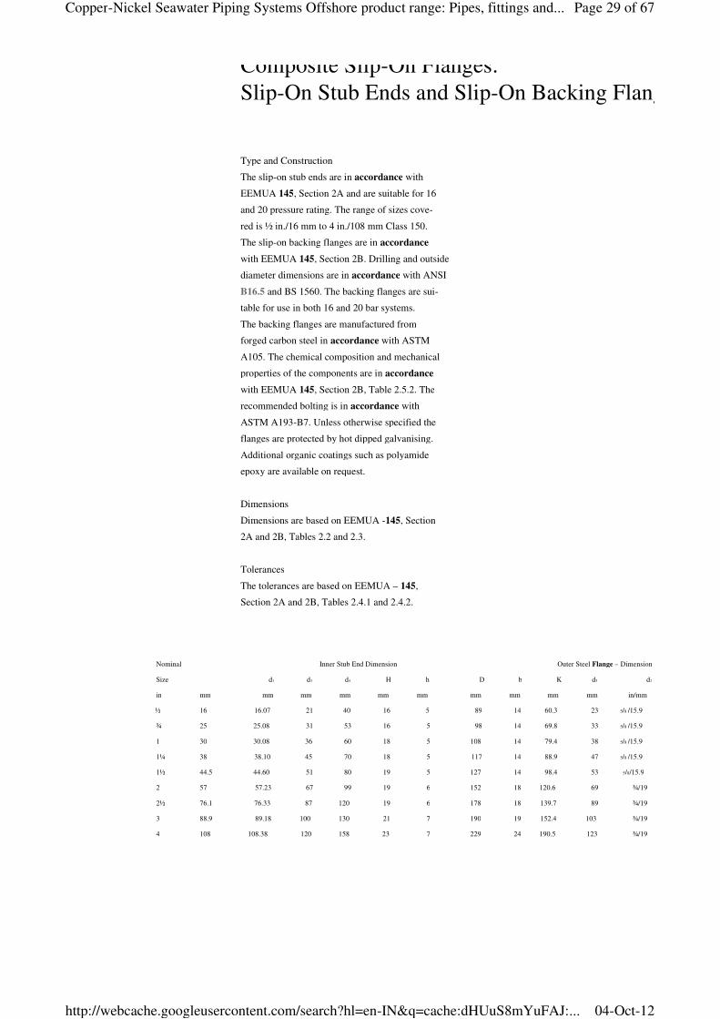
Type and Construction
The slip-on stub ends are in accordance with
EEMUA 145, Section 2A and are suitable for 16
and 20 pressure rating. The range of sizes cove-
red is ½ in./16 mm to 4 in./108 mm Class 150.
The slip-on backing flanges are in accordance
with EEMUA 145, Section 2B. Drilling and outside
diameter dimensions are in accordance with ANSI
B16.5 and BS 1560. The backing flanges are sui-
table for use in both 16 and 20 bar systems.
The backing flanges are manufactured from
forged carbon steel in accordance with ASTM
A105. The chemical composition and mechanical
properties of the components are in accordance
with EEMUA 145, Section 2B, Table 2.5.2. The
recommended bolting is in accordance with
ASTM A193-B7. Unless otherwise specified the
flanges are protected by hot dipped galvanising.
Additional organic coatings such as polyamide
epoxy are available on request.
Dimensions
Dimensions are based on EEMUA -145, Section
2A and 2B, Tables 2.2 and 2.3.
Tolerances
The tolerances are based on EEMUA – 145,
Section 2A and 2B, Tables 2.4.1 and 2.4.2.
Composite Slip-On Flanges:
Slip-On Stub Ends and Slip-On Backing Flanges
Nominal Inner Stub End Dimension Outer Steel Flange – Dimension
Size d1 d3 d4 H h D b K d5 d2
in mm mm mm mm mm mm mm mm mm mm in/mm
½ 16 16.07 21 40 16 5 89 14 60.3 23 5/8 /15.9
¾ 25 25.08 31 53 16 5 98 14 69.8 33 5/8 /15.9
1 30 30.08 36 60 18 5 108 14 79.4 38 5/8 /15.9
1¼ 38 38.10 45 70 18 5 117 14 88.9 47 5/8 /15.9
1½ 44.5 44.60 51 80 19 5 127 14 98.4 53 5/8/15.9
2 57 57.23 67 99 19 6 152 18 120.6 69 ¾/19
2½ 76.1 76.33 87 120 19 6 178 18 139.7 89 ¾/19
3 88.9 89.18 100 130 21 7 190 19 152.4 103 ¾/19
4 108 108.38 120 158 23 7 229 24 190.5 123 ¾/19
Page 29 of 67Copper-Nickel Seawater Piping Systems Offshore product range: Pipes, fittings and...
04-Oct-12http://webcache.googleusercontent.com/search?hl=en-IN&q=cache:dHUuS8mYuFAJ:...
KME Germany AG & Co. KG — OSNA®10
Page 22
Nominal Outside Thickn. Diameter Hub Dia
Size Diameter of of Hub at weld
of Flange Flange Chamfer
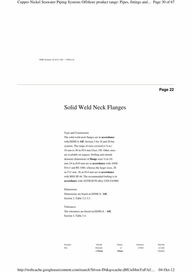
Type and Construction
The solid weld neck flanges are in accordance
with EEMUA 145, Section 3 for 16 and 20 bar
systems. The range of sizes covered is ½ in./
16 mm to 36 in./914 mm Class 150. Other sizes
are available on request. Drilling and outside
diameter dimensions of flange sizes ½ in./16
mm-24 in./610 mm are in accordance with ANSI
B16.5 and BS 1560, whereas the larger sizes, 28
in./711 mm -36 in./914 mm are in accordance
with MSS SP-44. The recommended bolting is in
accordance with ASTM B150 alloy UNS C63000.
Dimensions
Dimensions are based on EEMUA -145,
Section 3, Table 3.2-3.3.
Tolerances
The tolerances are based on EEMUA – 145,
Section 3, Table 3.4.
Solid Weld Neck Flanges
Page 30 of 67Copper-Nickel Seawater Piping Systems Offshore product range: Pipes, fittings and...
04-Oct-12http://webcache.googleusercontent.com/search?hl=en-IN&q=cache:dHUuS8mYuFAJ:...
20
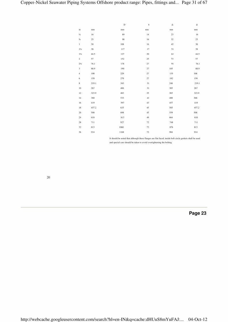
D b d6 d3
in mm mm mm mm mm
½ 16 89 14 23 16
¾ 25 98 16 32 25
1 30 108 16 42 30
1¼ 38 117 17 51 38
1½ 44.5 127 20 61 44.5
2 57 152 25 73 57
2½ 76.1 178 27 91 76.1
3 88.9 190 27 105 88.9
4 108 229 27 135 108
6 159 279 27 192 159
8 219.1 343 31 246 219.1
10 267 406 31 305 267
12 323.9 483 35 365 323.9
14 368 533 41 400 368
16 419 597 43 457 419
18 457.2 635 45 505 457.2
20 508 698 45 559 508
24 610 813 49 664 610
28 711 927 72 748 711
32 813 1060 72 876 813
36 914 1168 72 984 914
It should be noted that although these flanges are flat faced, inside bolt circle gaskets shall be used
and special care should be taken to avoid overtightening the bolting.
Page 23
Page 31 of 67Copper-Nickel Seawater Piping Systems Offshore product range: Pipes, fittings and...
04-Oct-12http://webcache.googleusercontent.com/search?hl=en-IN&q=cache:dHUuS8mYuFAJ:...
KME Germany AG & Co. KG — OSNA®10
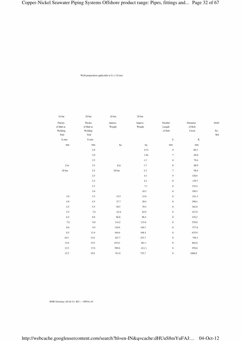
Weld preparation applicable to S1 ≥ 3,0 mm
16 bar 20 bar 16 bar 20 bar
Thickn. Thickn. Approx. Approx. Parallel Diameter Drilling
of Hub at of Hub at Weight Weight Length of Bolt
Welding Welding of Hub Circle No. of
End End Bolts
S1 min S1 min h K
mm mm kg kg mm mm
2.0 0.72 8 60.3
2.0 1.04 7 69.8
2.5 1.3 8 79.4
Use 2.5 Use 1.7 8 88.9
20 bar 2.5 20 bar 2.3 7 98.4
2.5 4.1 9 120.6
2.5 6.1 8 139.7
2.5 7.1 8 152.4
3.0 10.2 8 190.5
3.0 3.5 15.5 15.8 8 241.3
4.0 4.5 27.7 28.0 8 298.4
4.5 5.5 38.5 39.3 8 362.0
5.5 7.0 61.6 62.9 8 431.8
6.5 8.0 86.8 88.4 8 476.2
7.0 9.0 114.2 115.6 8 539.8
8.0 9.5 136.0 140.7 8 577.8
8.5 11.0 164.6 168.4 8 635.0
10.5 13.0 247.7 253.7 8 749.3
12.0 15.0 453.0 461.1 8 864.0
13.5 17.0 599.0 611.1 8 978.0
15.5 19.0 741.0 755.7 8 1086.0
Page 32 of 67Copper-Nickel Seawater Piping Systems Offshore product range: Pipes, fittings and...
04-Oct-12http://webcache.googleusercontent.com/search?hl=en-IN&q=cache:dHUuS8mYuFAJ:...
Page 24
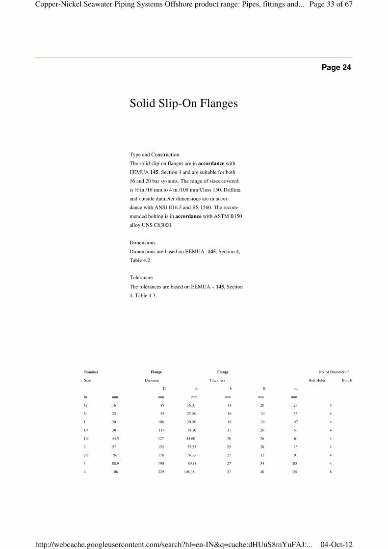
Nominal Flange Flange No. of Diameter of
Size Diameter Thickness Bolt Holes Bolt Holes
D d3 b H d6
in mm mm mm mm mm mm
½ 16 89 16.07 14 20 23 4
¾ 25 98 25.08 16 24 32 4
1 30 108 30.08 16 24 47 4
1¼ 38 117 38.10 17 26 51 4
1½ 44.5 127 44.60 20 26 61 4
2 57 152 57.23 25 28 73 4
2½ 76.1 178 76.33 27 32 91 4
3 88.9 190 89.18 27 34 105 4
4 108 229 108.38 27 40 135 8
Type and Construction
The solid slip-on flanges are in accordance with
EEMUA 145, Section 4 and are suitable for both
16 and 20 bar systems. The range of sizes covered
is ½ in./16 mm to 4 in./108 mm Class 150. Drilling
and outside diameter dimensions are in accor-
dance with ANSI B16.5 and BS 1560. The recom-
mended bolting is in accordance with ASTM B150
alloy UNS C63000.
Dimensions
Dimensions are based on EEMUA -145, Section 4,
Table 4.2.
Tolerances
The tolerances are based on EEMUA – 145, Section
4, Table 4.3.
Solid Slip-On Flanges
Page 33 of 67Copper-Nickel Seawater Piping Systems Offshore product range: Pipes, fittings and...
04-Oct-12http://webcache.googleusercontent.com/search?hl=en-IN&q=cache:dHUuS8mYuFAJ:...
22
Page 25
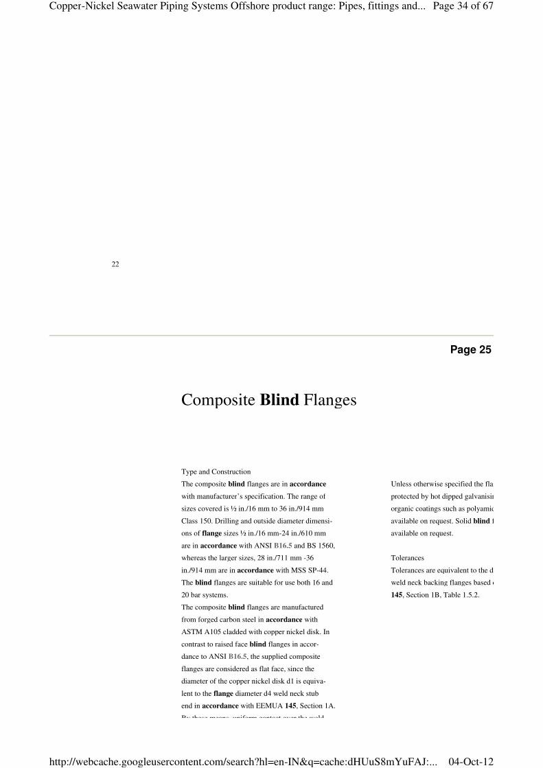
Composite Blind Flanges
Type and Construction
The composite blind flanges are in accordance
with manufacturer’s specification. The range of
sizes covered is ½ in./16 mm to 36 in./914 mm
Class 150. Drilling and outside diameter dimensi-
ons of flange sizes ½ in./16 mm-24 in./610 mm
are in accordance with ANSI B16.5 and BS 1560,
whereas the larger sizes, 28 in./711 mm -36
in./914 mm are in accordance with MSS SP-44.
The blind flanges are suitable for use both 16 and
20 bar systems.
The composite blind flanges are manufactured
from forged carbon steel in accordance with
ASTM A105 cladded with copper nickel disk. In
contrast to raised face blind flanges in accor-
dance to ANSI B16.5, the supplied composite
flanges are considered as flat face, since the
diameter of the copper nickel disk d1 is equiva-
lent to the flange diameter d4 weld neck stub
end in accordance with EEMUA 145, Section 1A.
By these means, uniform contact over the weld
Unless otherwise specified the flanges are
protected by hot dipped galvanising. Additional
organic coatings such as polyamide epoxy are
available on request. Solid blind flanges are
available on request.
Tolerances
Tolerances are equivalent to the dimensions for
weld neck backing flanges based on EEMUA
145, Section 1B, Table 1.5.2.
Page 34 of 67Copper-Nickel Seawater Piping Systems Offshore product range: Pipes, fittings and...
04-Oct-12http://webcache.googleusercontent.com/search?hl=en-IN&q=cache:dHUuS8mYuFAJ:...
KME Germany AG & Co. KG — OSNA®10
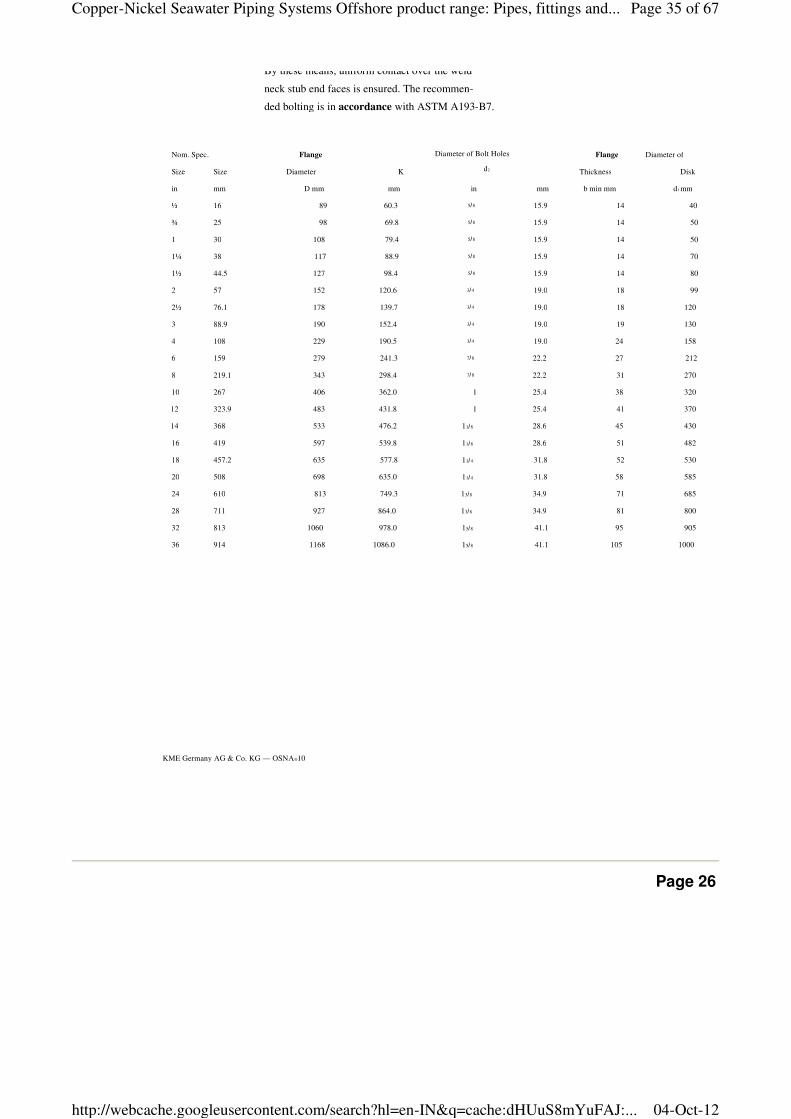
By these means, uniform contact over the weld
neck stub end faces is ensured. The recommen-
ded bolting is in accordance with ASTM A193-B7.
Nom. Spec. Flange Flange Diameter of
Size Size Diameter K Thickness Disk
in mm D mm mm in mm b min mm d1 mm
½ 16 89 60.3 5/8 15.9 14 40
¾ 25 98 69.8 5/8 15.9 14 50
1 30 108 79.4 5/8 15.9 14 50
1¼ 38 117 88.9 5/8 15.9 14 70
1½ 44.5 127 98.4 5/8 15.9 14 80
2 57 152 120.6 3/4 19.0 18 99
2½ 76.1 178 139.7 3/4 19.0 18 120
3 88.9 190 152.4 3/4 19.0 19 130
4 108 229 190.5 3/4 19.0 24 158
6 159 279 241.3 7/8 22.2 27 212
8 219.1 343 298.4 7/8 22.2 31 270
10 267 406 362.0 1 25.4 38 320
12 323.9 483 431.8 1 25.4 41 370
14 368 533 476.2 11/8 28.6 45 430
16 419 597 539.8 11/8 28.6 51 482
18 457.2 635 577.8 11/4 31.8 52 530
20 508 698 635.0 11/4 31.8 58 585
24 610 813 749.3 13/8 34.9 71 685
28 711 927 864.0 13/8 34.9 81 800
32 813 1060 978.0 15/8 41.1 95 905
36 914 1168 1086.0 15/8 41.1 105 1000
Diameter of Bolt Holes
d2
Page 26
Page 35 of 67Copper-Nickel Seawater Piping Systems Offshore product range: Pipes, fittings and...
04-Oct-12http://webcache.googleusercontent.com/search?hl=en-IN&q=cache:dHUuS8mYuFAJ:...
Capillary Brazing, Socket Weld Fittings
and Miscellaneous
Page 36 of 67Copper-Nickel Seawater Piping Systems Offshore product range: Pipes, fittings and...
04-Oct-12http://webcache.googleusercontent.com/search?hl=en-IN&q=cache:dHUuS8mYuFAJ:...
24
Page 27
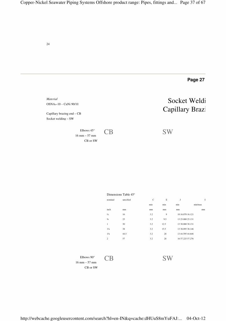
Socket Welding Elbow 45°/90°
Capillary Brazing Elbow 45°/90°
Material
OSNA®-10 – CuNi 90/10
Capillary brazing end – CB
Socket welding – SW
CB SW
CB SWElbows 90°
16 mm – 57 mm
CB or SW
Elbows 45°
16 mm – 57 mm
CB or SW
Dimensions Table 45°
nominal specified C E J B
min min min min/max
inch mm mm mm mm mm
½ 16 3.2 9 10 16.070 16.121
¾ 25 3.2 9.5 13 25.080 25.131
1 30 3.2 12.5 13 30.080 30.131
1¼ 38 3.2 15.5 13 38.095 38.146
1½ 44.5 3.2 20 13 44.595 44.646
2 57 3.2 20 16 57.225 57.276
Page 37 of 67Copper-Nickel Seawater Piping Systems Offshore product range: Pipes, fittings and...
04-Oct-12http://webcache.googleusercontent.com/search?hl=en-IN&q=cache:dHUuS8mYuFAJ:...
KME Germany AG & Co. KG — OSNA®10
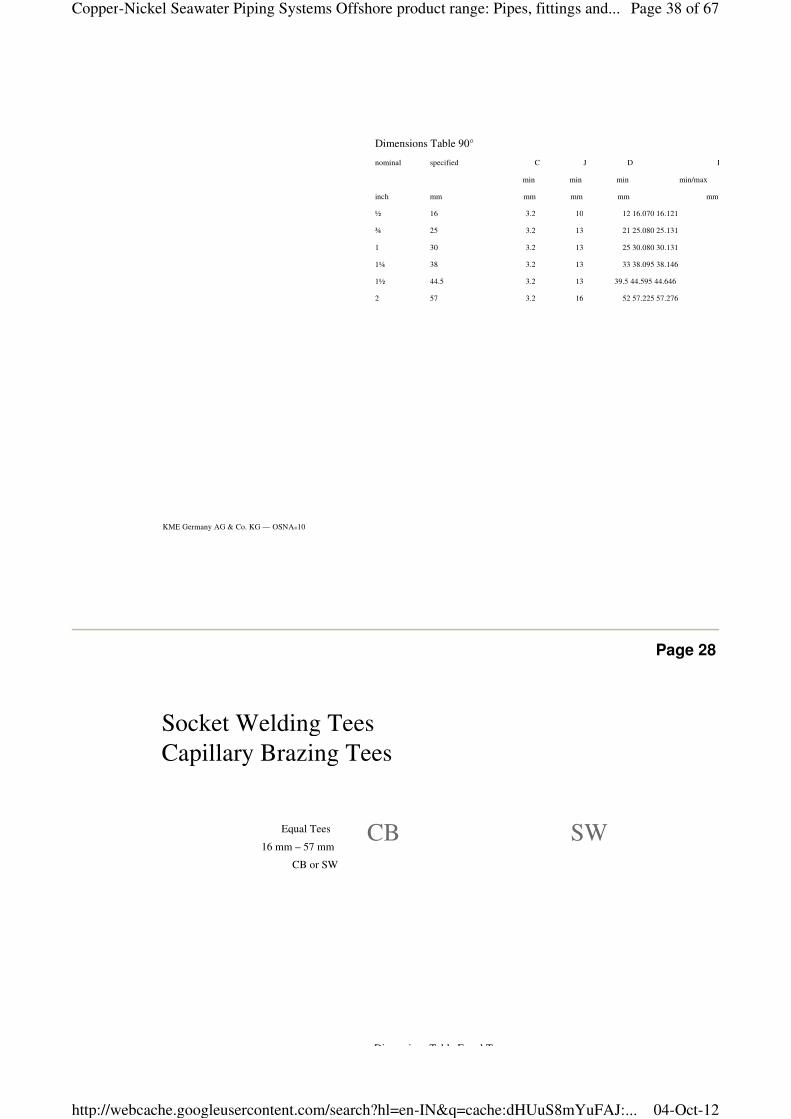
Dimensions Table 90°
nominal specified C J D B
min min min min/max
inch mm mm mm mm mm
½ 16 3.2 10 12 16.070 16.121
¾ 25 3.2 13 21 25.080 25.131
1 30 3.2 13 25 30.080 30.131
1¼ 38 3.2 13 33 38.095 38.146
1½ 44.5 3.2 13 39.5 44.595 44.646
2 57 3.2 16 52 57.225 57.276
Page 28
Equal Tees
16 mm – 57 mm
CB or SW
Socket Welding Tees
Capillary Brazing Tees
Dimensions Table Equal Tees
CB SW
Page 38 of 67Copper-Nickel Seawater Piping Systems Offshore product range: Pipes, fittings and...
04-Oct-12http://webcache.googleusercontent.com/search?hl=en-IN&q=cache:dHUuS8mYuFAJ:...
26
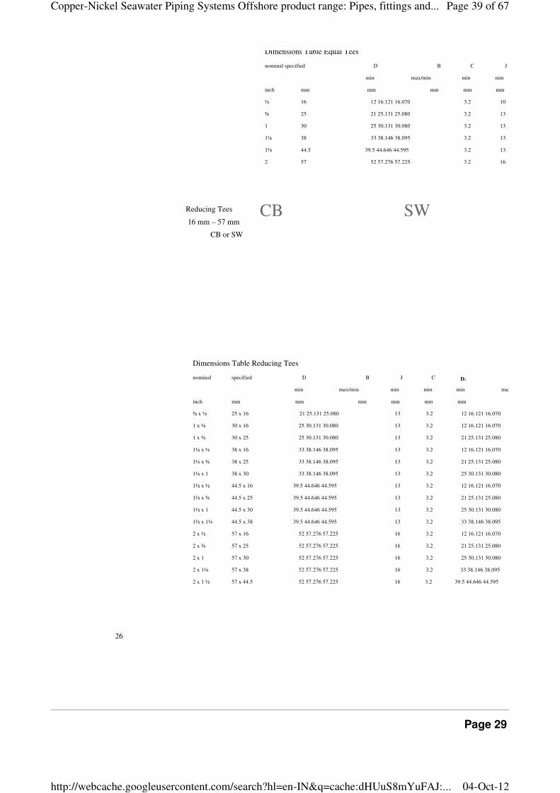
Reducing Tees
16 mm – 57 mm
CB or SW
Dimensions Table Equal Tees
nominal specified D B C J
min max/min min min
inch mm mm mm mm mm
½ 16 12 16.121 16.070 3.2 10
¾ 25 21 25.131 25.080 3.2 13
1 30 25 30.131 30.080 3.2 13
1¼ 38 33 38.146 38.095 3.2 13
1½ 44.5 39.5 44.646 44.595 3.2 13
2 57 52 57.276 57.225 3.2 16
Dimensions Table Reducing Tees
nominal specified D B J C D1
min max/min min min min max/min
inch mm mm mm mm mm mm
¾ x ½ 25 x 16 21 25.131 25.080 13 3.2 12 16.121 16.070
1 x ½ 30 x 16 25 30.131 30.080 13 3.2 12 16.121 16.070
1 x ¾ 30 x 25 25 30.131 30.080 13 3.2 21 25.131 25.080
1¼ x ½ 38 x 16 33 38.146 38.095 13 3.2 12 16.121 16.070
1¼ x ¾ 38 x 25 33 38.146 38.095 13 3.2 21 25.131 25.080
1¼ x 1 38 x 30 33 38.146 38.095 13 3.2 25 30.131 30.080
1½ x ½ 44.5 x 16 39.5 44.646 44.595 13 3.2 12 16.121 16.070
1½ x ¾ 44.5 x 25 39.5 44.646 44.595 13 3.2 21 25.131 25.080
1½ x 1 44.5 x 30 39.5 44.646 44.595 13 3.2 25 30.131 30.080
1½ x 1¼ 44.5 x 38 39.5 44.646 44.595 13 3.2 33 38.146 38.095
2 x ½ 57 x 16 52 57.276 57.225 16 3.2 12 16.121 16.070
2 x ¾ 57 x 25 52 57.276 57.225 16 3.2 21 25.131 25.080
2 x 1 57 x 30 52 57.276 57.225 16 3.2 25 30.131 30.080
2 x 1¼ 57 x 38 52 57.276 57.225 16 3.2 33 38.146 38.095
2 x 1 ½ 57 x 44.5 52 57.276 57.225 16 3.2 39.5 44.646 44.595
CB SW
Page 29
Page 39 of 67Copper-Nickel Seawater Piping Systems Offshore product range: Pipes, fittings and...
04-Oct-12http://webcache.googleusercontent.com/search?hl=en-IN&q=cache:dHUuS8mYuFAJ:...
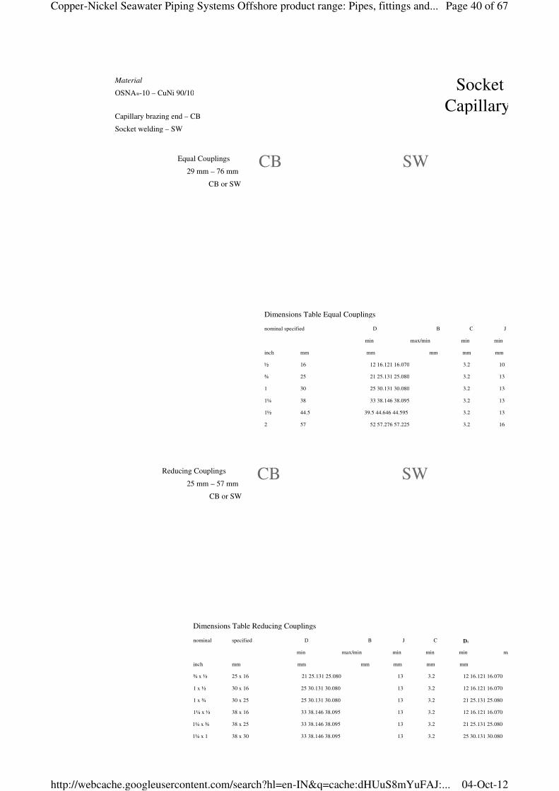
Reducing Couplings
25 mm – 57 mm
CB or SW
Socket Welding Couplings
Capillary Brazing Couplings
Dimensions Table Equal Couplings
nominal specified D B C J
min max/min min min
inch mm mm mm mm mm
½ 16 12 16.121 16.070 3.2 10
¾ 25 21 25.131 25.080 3.2 13
1 30 25 30.131 30.080 3.2 13
1¼ 38 33 38.146 38.095 3.2 13
1½ 44.5 39.5 44.646 44.595 3.2 13
2 57 52 57.276 57.225 3.2 16
Equal Couplings
29 mm – 76 mm
CB or SW
Dimensions Table Reducing Couplings
nominal specified D B J C D1
min max/min min min min max/min
inch mm mm mm mm mm mm
¾ x ½ 25 x 16 21 25.131 25.080 13 3.2 12 16.121 16.070
1 x ½ 30 x 16 25 30.131 30.080 13 3.2 12 16.121 16.070
1 x ¾ 30 x 25 25 30.131 30.080 13 3.2 21 25.131 25.080
1¼ x ½ 38 x 16 33 38.146 38.095 13 3.2 12 16.121 16.070
1¼ x ¾ 38 x 25 33 38.146 38.095 13 3.2 21 25.131 25.080
1¼ x 1 38 x 30 33 38.146 38.095 13 3.2 25 30.131 30.080
Material
OSNA®-10 – CuNi 90/10
Capillary brazing end – CB
Socket welding – SW
CB SW
CB SW
Page 40 of 67Copper-Nickel Seawater Piping Systems Offshore product range: Pipes, fittings and...
04-Oct-12http://webcache.googleusercontent.com/search?hl=en-IN&q=cache:dHUuS8mYuFAJ:...
KME Germany AG & Co. KG — OSNA®10
1½ x ½ 44.5 x 16 39.5 44.646 44.595 13 3.2 12 16.121 16.070
1½ x ¾ 44.5 x 25 39.5 44.646 44.595 13 3.2 21 25.131 25.080
1½ x 1 44.5 x 30 39.5 44.646 44.595 13 3.2 25 30.131 30.080
1½ x 1¼ 44.5 x 38 39.5 44.646 44.595 13 3.2 33 38.146 38.095
2 x ½ 57 x 16 52 57.276 57.225 16 3.2 12 16.121 16.070
2 x ¾ 57 x 25 52 57.276 57.225 16 3.2 21 25.131 25.080
2 x 1 57 x 30 52 57.276 57.225 16 3.2 25 30.131 30.080
2 x 1¼ 57 x 38 52 57.276 57.225 16 3.2 33 38.146 38.095
2 x 1 ½ 57 x 44.5 52 57.276 57.225 16 3.2 39.5 44.646 44.595
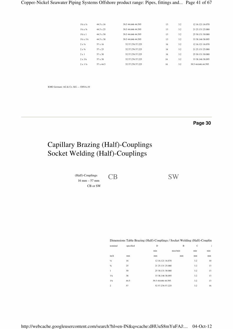
Page 30
Capillary Brazing (Half)-Couplings
Socket Welding (Half)-Couplings
Dimensions Table Brazing (Half)-Couplings / Socket Welding (Half)-Couplings
nominal specified D B C J
min max/min min min
inch mm mm mm mm mm
½ 16 12 16.121 16.070 3.2 10
¾ 25 21 25.131 25.080 3.2 13
1 30 25 30.131 30.080 3.2 13
1¼ 38 33 38.146 38.095 3.2 13
1½ 44.5 39.5 44.646 44.595 3.2 13
2 57 52 57.276 57.225 3.2 16
(Half)-Couplings
16 mm – 57 mm
CB or SW
CB SW
Page 41 of 67Copper-Nickel Seawater Piping Systems Offshore product range: Pipes, fittings and...
04-Oct-12http://webcache.googleusercontent.com/search?hl=en-IN&q=cache:dHUuS8mYuFAJ:...
28
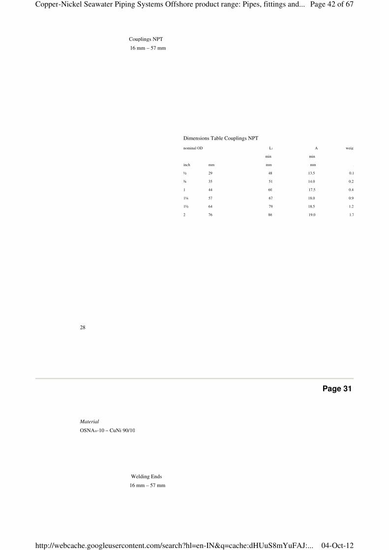
Couplings NPT
16 mm – 57 mm
Dimensions Table Couplings NPT
nominal OD L1 A weight
min min
inch mm mm mm ~kg
½ 29 48 13.5 0.188
¾ 35 51 14.0 0.263
1 44 60 17.5 0.490
1¼ 57 67 18.0 0.902
1½ 64 79 18.5 1.273
2 76 86 19.0 1.701
Page 31
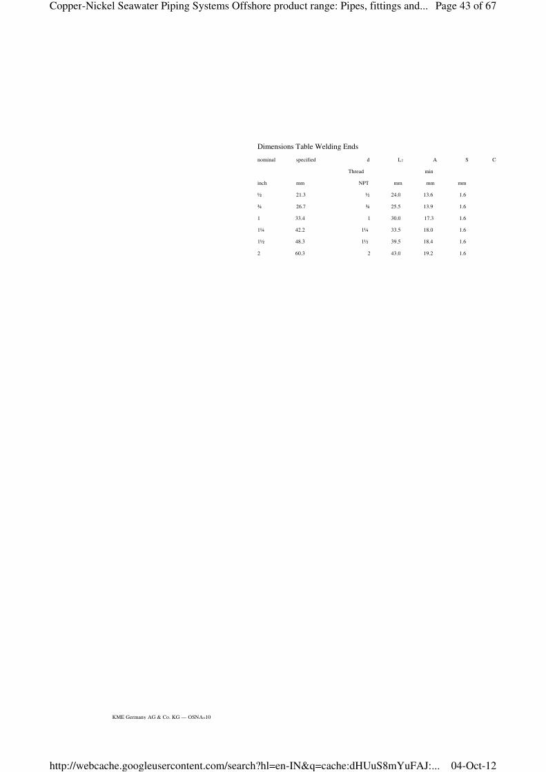
Material
OSNA®-10 – CuNi 90/10
Welding Ends
16 mm – 57 mm
Page 42 of 67Copper-Nickel Seawater Piping Systems Offshore product range: Pipes, fittings and...
04-Oct-12http://webcache.googleusercontent.com/search?hl=en-IN&q=cache:dHUuS8mYuFAJ:...
KME Germany AG & Co. KG — OSNA®10
Dimensions Table Welding Ends
nominal specified d L2 A S Coupling
Thread min
inch mm NPT mm mm mm
½ 21.3 ½ 24.0 13.6 1.6
¾ 26.7 ¾ 25.5 13.9 1.6
1 33.4 1 30.0 17.3 1.6
1¼ 42.2 1¼ 33.5 18.0 1.6
1½ 48.3 1½ 39.5 18.4 1.6
2 60.3 2 43.0 19.2 1.6
Page 43 of 67Copper-Nickel Seawater Piping Systems Offshore product range: Pipes, fittings and...
04-Oct-12http://webcache.googleusercontent.com/search?hl=en-IN&q=cache:dHUuS8mYuFAJ:...
Page 32
Page 44 of 67Copper-Nickel Seawater Piping Systems Offshore product range: Pipes, fittings and...
04-Oct-12http://webcache.googleusercontent.com/search?hl=en-IN&q=cache:dHUuS8mYuFAJ:...
30
Page 33
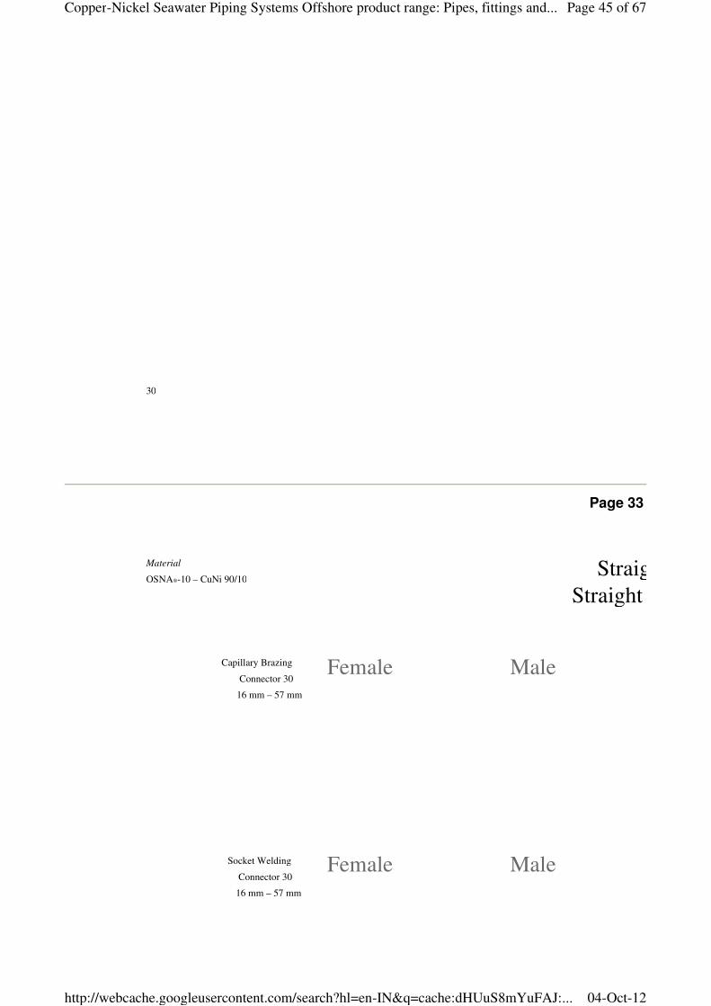
Straight Male Connector
Straight Female Connector
Capillary Brazing
Connector 30
16 mm – 57 mm
Socket Welding
Connector 30
16 mm – 57 mm
Material
OSNA®-10 – CuNi 90/10
Female Male
Female Male
Page 45 of 67Copper-Nickel Seawater Piping Systems Offshore product range: Pipes, fittings and...
04-Oct-12http://webcache.googleusercontent.com/search?hl=en-IN&q=cache:dHUuS8mYuFAJ:...
KME Germany AG & Co. KG — OSNA®10
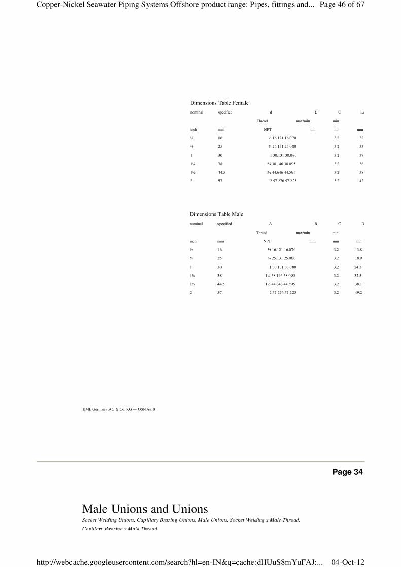
Dimensions Table Female
nominal specified d B C L1
Thread max/min min
inch mm NPT mm mm mm
½ 16 ½ 16.121 16.070 3.2 32
¾ 25 ¾ 25.131 25.080 3.2 33
1 30 1 30.131 30.080 3.2 37
1¼ 38 1¼ 38.146 38.095 3.2 38
1½ 44.5 1½ 44.646 44.595 3.2 38
2 57 2 57.276 57.225 3.2 42
Dimensions Table Male
nominal specified A B C D
Thread max/min min
inch mm NPT mm mm mm
½ 16 ½ 16.121 16.070 3.2 13.8
¾ 25 ¾ 25.131 25.080 3.2 18.9
1 30 1 30.131 30.080 3.2 24.3
1¼ 38 1¼ 38.146 38.095 3.2 32.5
1½ 44.5 1½ 44.646 44.595 3.2 38.1
2 57 2 57.276 57.225 3.2 49.2
Page 34
Male Unions and UnionsSocket Welding Unions, Capillary Brazing Unions, Male Unions, Socket Welding x Male Thread,
Capillary Brazing x Male Thread
Page 46 of 67Copper-Nickel Seawater Piping Systems Offshore product range: Pipes, fittings and...
04-Oct-12http://webcache.googleusercontent.com/search?hl=en-IN&q=cache:dHUuS8mYuFAJ:...
Capillary Brazing x Male Thread
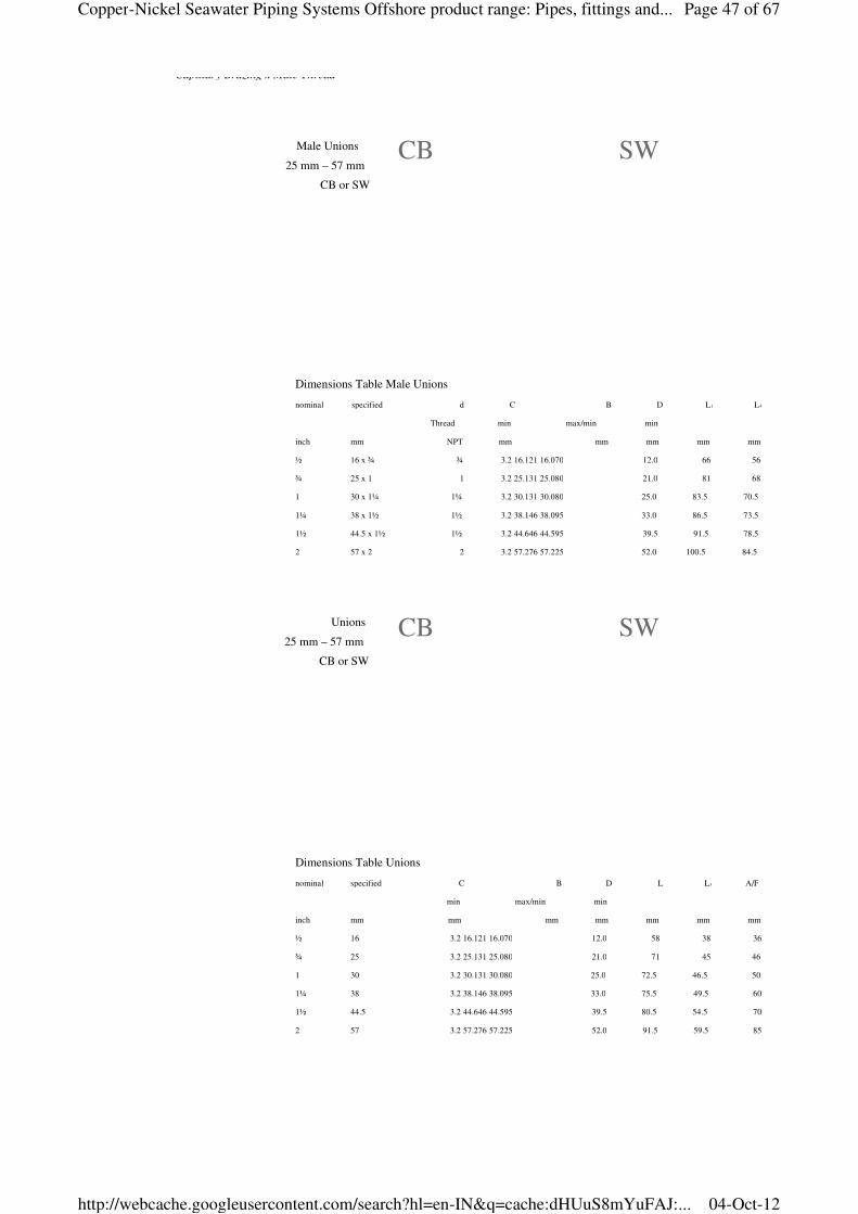
Male Unions
25 mm – 57 mm
CB or SW
Unions
25 mm – 57 mm
CB or SW
Dimensions Table Unions
nominal C B D L L3 A/F
min max/min min
inch mm mm mm mm mm mm mm
½ 16 3.2 16.121 16.070 12.0 58 38 36
¾ 25 3.2 25.131 25.080 21.0 71 45 46
1 30 3.2 30.131 30.080 25.0 72.5 46.5 50
1¼ 38 3.2 38.146 38.095 33.0 75.5 49.5 60
1½ 44.5 3.2 44.646 44.595 39.5 80.5 54.5 70
2 57 3.2 57.276 57.225 52.0 91.5 59.5 85
specified
Dimensions Table Male Unions
nominal d C B D L1 L4
Thread min max/min min
inch mm NPT mm mm mm mm mm
½ 16 x ¾ ¾ 3.2 16.121 16.070 12.0 66 56
¾ 25 x 1 1 3.2 25.131 25.080 21.0 81 68
1 30 x 1¼ 1¼ 3.2 30.131 30.080 25.0 83.5 70.5
1¼ 38 x 1½ 1½ 3.2 38.146 38.095 33.0 86.5 73.5
1½ 44.5 x 1½ 1½ 3.2 44.646 44.595 39.5 91.5 78.5
2 57 x 2 2 3.2 57.276 57.225 52.0 100.5 84.5
specified
CB SW
CB SW
Page 47 of 67Copper-Nickel Seawater Piping Systems Offshore product range: Pipes, fittings and...
04-Oct-12http://webcache.googleusercontent.com/search?hl=en-IN&q=cache:dHUuS8mYuFAJ:...
32
Page 35
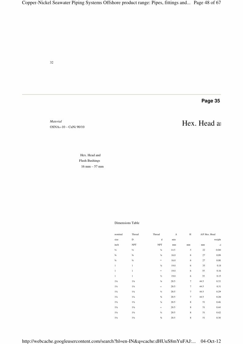
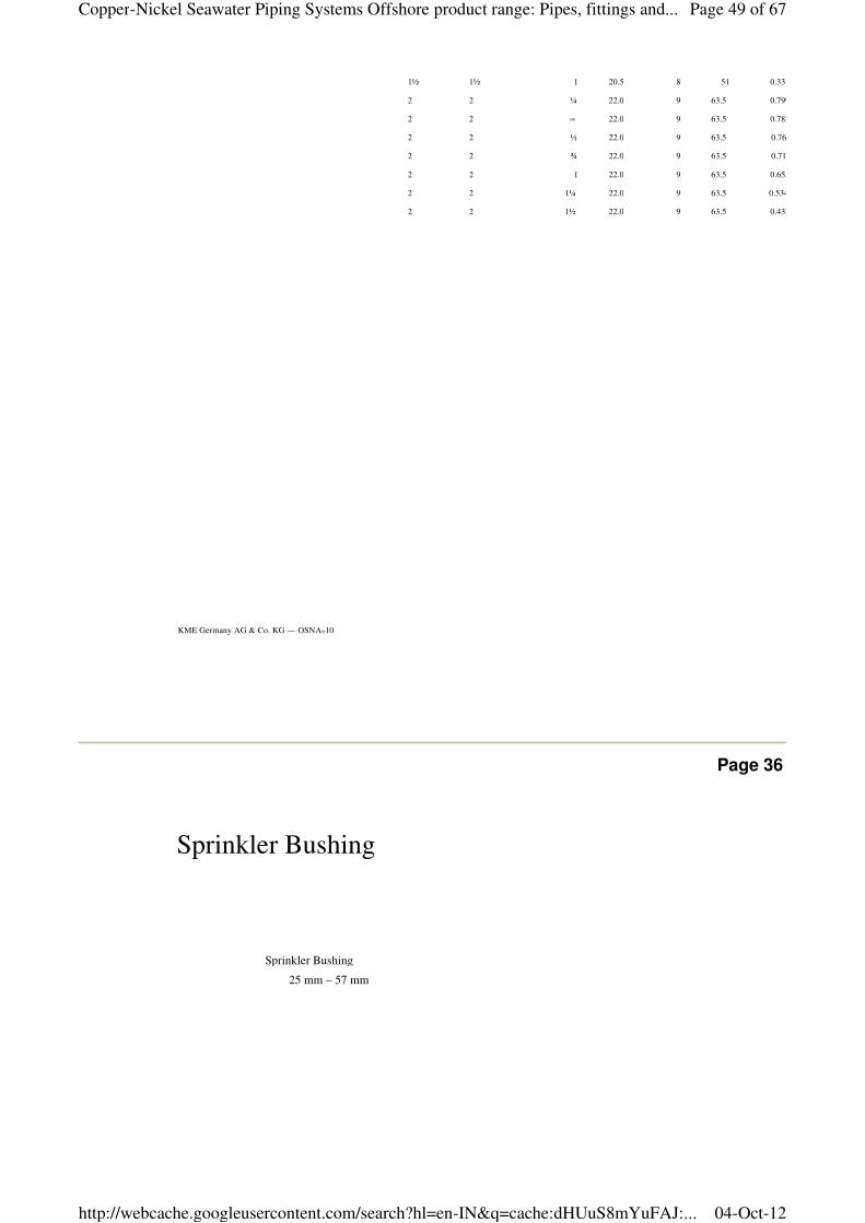
Hex. Head and Flush Bushings
Hex. Head and
Flush Bushings
16 mm – 57 mm
Dimensions Table
nominal Thread Thread A H A/F Hex. Head
size D d min weight
inch NPT NPT mm mm mm ~kg
½ ½ ¼ 14.5 5 22 0.048
¾ ¾ ¼ 16.0 6 27 0.094
¾ ¾ 3/8 16.0 6 27 0.082
1 1 ¼ 19.0 6 35 0.181
1 1 3/8 19.0 6 35 0.167
1 1 ½ 19.0 6 35 0.150
1¼ 1¼ ¼ 20.5 7 44.5 0.333
1¼ 1¼ 3/8 20.5 7 44.5 0.318
1¼ 1¼ ½ 20.5 7 44.5 0.299
1¼ 1¼ ¾ 20.5 7 44.5 0.260
1½ 1½ ¼ 20.5 8 51 0.463
1½ 1½ 3/8 20.5 8 51 0.447
1½ 1½ ½ 20.5 8 51 0.428
1½ 1½ ¾ 20.5 8 51 0.387
1½ 1½ 1 20.5 8 51 0.331
Material
OSNA®-10 – CuNi 90/10
Page 48 of 67Copper-Nickel Seawater Piping Systems Offshore product range: Pipes, fittings and...
04-Oct-12http://webcache.googleusercontent.com/search?hl=en-IN&q=cache:dHUuS8mYuFAJ:...
KME Germany AG & Co. KG — OSNA®10
1½ 1½ 1 20.5 8 51 0.331
2 2 ¼ 22.0 9 63.5 0.799
2 2 3/8 22.0 9 63.5 0.782
2 2 ½ 22.0 9 63.5 0.761
2 2 ¾ 22.0 9 63.5 0.716
2 2 1 22.0 9 63.5 0.655
2 2 1¼ 22.0 9 63.5 0.534
2 2 1½ 22.0 9 63.5 0.432
Page 36
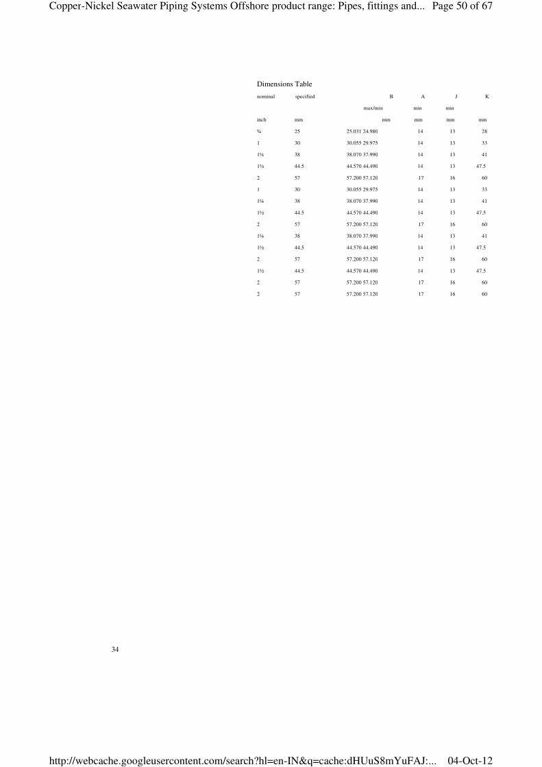
Sprinkler Bushing
Sprinkler Bushing
25 mm – 57 mm
Page 49 of 67Copper-Nickel Seawater Piping Systems Offshore product range: Pipes, fittings and...
04-Oct-12http://webcache.googleusercontent.com/search?hl=en-IN&q=cache:dHUuS8mYuFAJ:...
34
Dimensions Table
nominal B A J K
max/min min min
inch mm mm mm mm mm
¾ 25 25.031 24.980 14 13 28
1 30 30.055 29.975 14 13 33
1¼ 38 38.070 37.990 14 13 41
1½ 44.5 44.570 44.490 14 13 47.5
2 57 57.200 57.120 17 16 60
1 30 30.055 29.975 14 13 33
1¼ 38 38.070 37.990 14 13 41
1½ 44.5 44.570 44.490 14 13 47.5
2 57 57.200 57.120 17 16 60
1¼ 38 38.070 37.990 14 13 41
1½ 44.5 44.570 44.490 14 13 47.5
2 57 57.200 57.120 17 16 60
1½ 44.5 44.570 44.490 14 13 47.5
2 57 57.200 57.120 17 16 60
2 57 57.200 57.120 17 16 60
specified
Page 50 of 67Copper-Nickel Seawater Piping Systems Offshore product range: Pipes, fittings and...
04-Oct-12http://webcache.googleusercontent.com/search?hl=en-IN&q=cache:dHUuS8mYuFAJ:...
Page 37
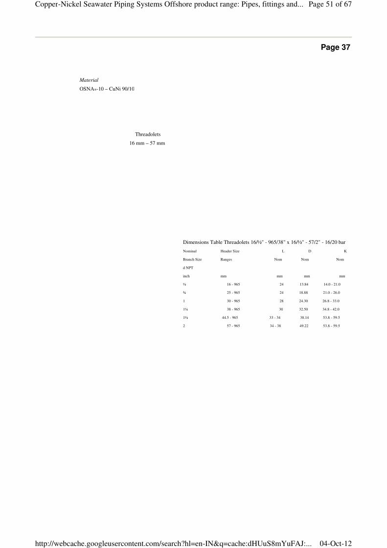
Material
OSNA®-10 – CuNi 90/10
Dimensions Table Threadolets 16/½" - 965/38" x 16/½" - 57/2" - 16/20 bar
Nominal Header Size L D K
Branch Size Ranges Nom Nom Nom
d NPT
inch mm mm mm mm
½ 16 - 965 24 13.84 14.0 - 21.0
¾ 25 - 965 24 18.88 21.0 - 26.0
1 30 - 965 28 24.30 26.8 - 33.0
1¼ 38 - 965 30 32.50 34.8 - 42.0
1½ 44.5 - 965 33 - 34 38.14 53.8 - 59.5
2 57 - 965 34 - 38 49.22 53.8 - 59.5
Threadolets
16 mm – 57 mm
Page 51 of 67Copper-Nickel Seawater Piping Systems Offshore product range: Pipes, fittings and...
04-Oct-12http://webcache.googleusercontent.com/search?hl=en-IN&q=cache:dHUuS8mYuFAJ:...
KME Germany AG & Co. KG — OSNA®10
Page 38
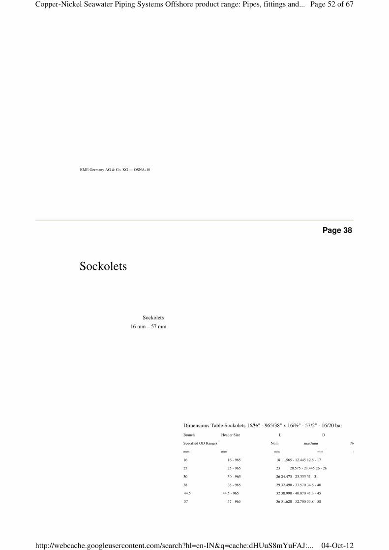
Sockolets
16 mm – 57 mm
Sockolets
Dimensions Table Sockolets 16/½" - 965/38" x 16/½" - 57/2" - 16/20 bar
Branch Header Size L D
Specified OD Ranges Nom max/min Nom
mm mm mm mm mm
16 16 - 965 18 11.565 - 12.445 12.8 - 17
25 25 - 965 23 20.575 - 21.445 26 - 26
30 30 - 965 26 24.475 - 25.555 31 - 31
38 38 - 965 29 32.490 - 33.570 34.8 - 40
44.5 44.5 - 965 32 38.990 - 40.070 41.3 - 45
57 57 - 965 36 51.620 - 52.700 53.8 - 58
Page 52 of 67Copper-Nickel Seawater Piping Systems Offshore product range: Pipes, fittings and...
04-Oct-12http://webcache.googleusercontent.com/search?hl=en-IN&q=cache:dHUuS8mYuFAJ:...
36
Page 39
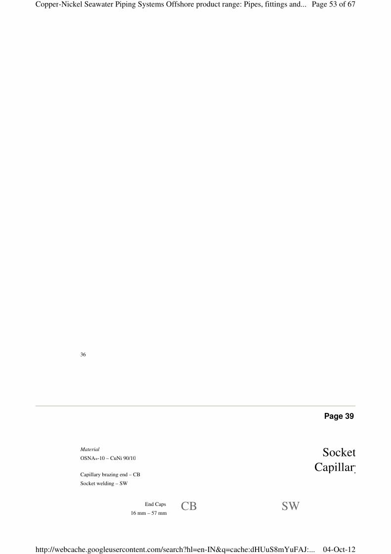
End Caps
16 mm – 57 mm
Material
OSNA®-10 – CuNi 90/10
Capillary brazing end – CB
Socket welding – SW
Socket Welding End Caps
Capillary Brazing End Caps
CB SW
Page 53 of 67Copper-Nickel Seawater Piping Systems Offshore product range: Pipes, fittings and...
04-Oct-12http://webcache.googleusercontent.com/search?hl=en-IN&q=cache:dHUuS8mYuFAJ:...
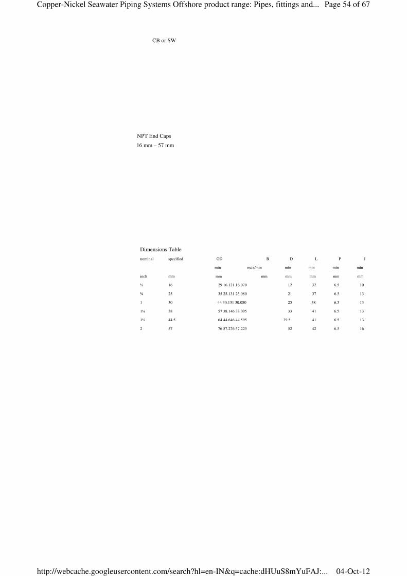
CB or SW
NPT End Caps
16 mm – 57 mm
Dimensions Table
nominal specified OD B D L P J
min max/min min min min min
inch mm mm mm mm mm mm mm
½ 16 29 16.121 16.070 12 32 6.5 10
¾ 25 35 25.131 25.080 21 37 6.5 13
1 30 44 30.131 30.080 25 38 6.5 13
1¼ 38 57 38.146 38.095 33 41 6.5 13
1½ 44.5 64 44.646 44.595 39.5 41 6.5 13
2 57 76 57.276 57.225 52 42 6.5 16
Page 54 of 67Copper-Nickel Seawater Piping Systems Offshore product range: Pipes, fittings and...
04-Oct-12http://webcache.googleusercontent.com/search?hl=en-IN&q=cache:dHUuS8mYuFAJ:...
KME Germany AG & Co. KG — OSNA®10
Page 40
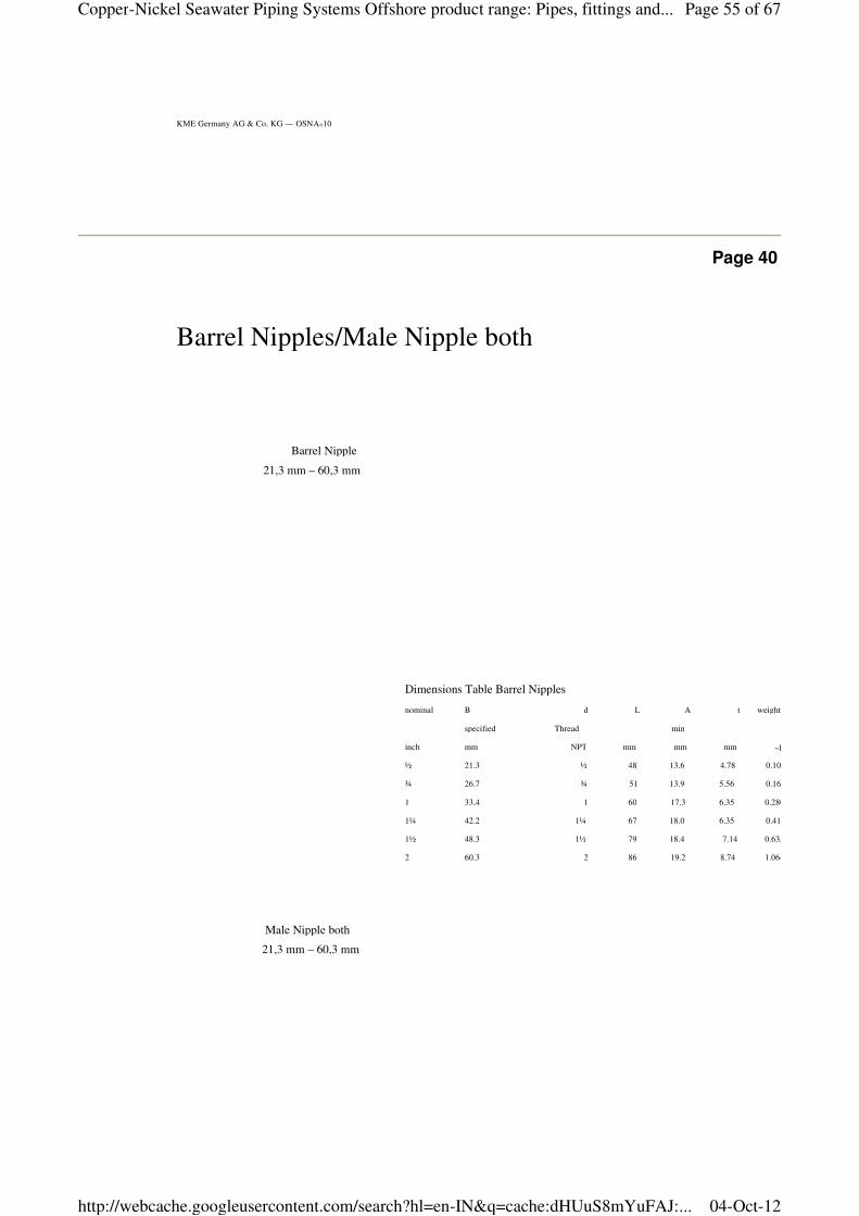
Dimensions Table Barrel Nipples
nominal B d L A t weight
specified Thread min
inch mm NPT mm mm mm ~kg
½ 21.3 ½ 48 13.6 4.78 0.103
¾ 26.7 ¾ 51 13.9 5.56 0.163
1 33.4 1 60 17.3 6.35 0.280
1¼ 42.2 1¼ 67 18.0 6.35 0.415
1½ 48.3 1½ 79 18.4 7.14 0.635
2 60.3 2 86 19.2 8.74 1.064
Barrel Nipple
21,3 mm – 60,3 mm
Male Nipple both
21,3 mm – 60,3 mm
Barrel Nipples/Male Nipple both
Page 55 of 67Copper-Nickel Seawater Piping Systems Offshore product range: Pipes, fittings and...
04-Oct-12http://webcache.googleusercontent.com/search?hl=en-IN&q=cache:dHUuS8mYuFAJ:...
38
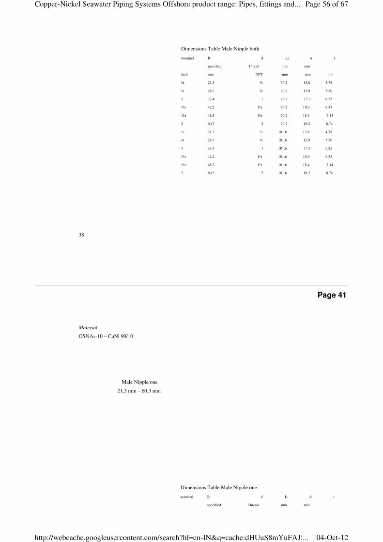
Dimensions Table Male Nipple both
nominal B d L1 A t
specified Thread min min
inch mm NPT mm mm mm
½ 21.3 ½ 76.2 13.6 4.78
¾ 26.7 ¾ 76.2 13.9 5.56
1 33.4 1 76.2 17.3 6.35
1¼ 42.2 1¼ 76.2 18.0 6.35
1½ 48.3 1½ 76.2 18.4 7.14
2 60.3 2 76.2 19.2 8.74
½ 21.3 ½ 101.6 13.6 4.78
¾ 26.7 ¾ 101.6 13.9 5.56
1 33.4 1 101.6 17.3 6.35
1¼ 42.2 1¼ 101.6 18.0 6.35
1½ 48.3 1½ 101.6 18.4 7.14
2 60.3 2 101.6 19.2 8.74
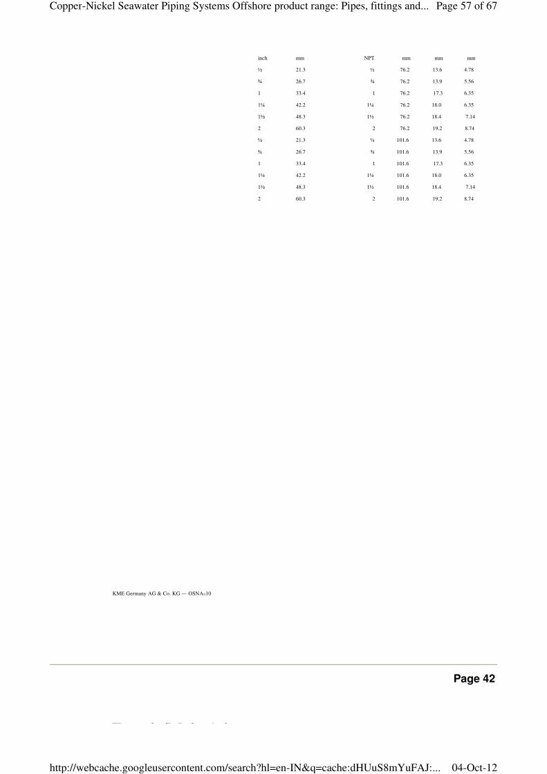
Page 41
Male Nipple one
21,3 mm – 60,3 mm
Material
OSNA®-10 – CuNi 90/10
Dimensions Table Male Nipple one
nominal B d L1 A t
specified Thread min min
Page 56 of 67Copper-Nickel Seawater Piping Systems Offshore product range: Pipes, fittings and...
04-Oct-12http://webcache.googleusercontent.com/search?hl=en-IN&q=cache:dHUuS8mYuFAJ:...
KME Germany AG & Co. KG — OSNA®10
specified Thread min min
inch mm NPT mm mm mm
½ 21.3 ½ 76.2 13.6 4.78
¾ 26.7 ¾ 76.2 13.9 5.56
1 33.4 1 76.2 17.3 6.35
1¼ 42.2 1¼ 76.2 18.0 6.35
1½ 48.3 1½ 76.2 18.4 7.14
2 60.3 2 76.2 19.2 8.74
½ 21.3 ½ 101.6 13.6 4.78
¾ 26.7 ¾ 101.6 13.9 5.56
1 33.4 1 101.6 17.3 6.35
1¼ 42.2 1¼ 101.6 18.0 6.35
1½ 48.3 1½ 101.6 18.4 7.14
2 60.3 2 101.6 19.2 8.74
Page 42
Female/Male Adaptor
Page 57 of 67Copper-Nickel Seawater Piping Systems Offshore product range: Pipes, fittings and...
04-Oct-12http://webcache.googleusercontent.com/search?hl=en-IN&q=cache:dHUuS8mYuFAJ:...
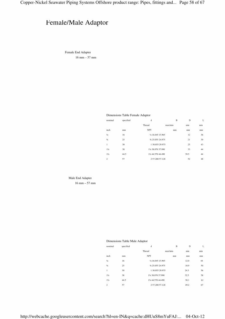
Female/Male Adaptor
Female End Adapter
16 mm – 57 mm
Male End Adapter
16 mm – 57 mm
Dimensions Table Female Adaptor
nominal d B D L
Thread max/min min min
inch mm NPT mm mm mm
½ 16 ½ 16.045 15.965 12 36
¾ 25 ¾ 25.055 24.975 21 39
1 30 1 30.055 29.975 25 43
1¼ 38 1¼ 38.070 37.990 33 44
1½ 44.5 1½ 44.570 44.490 39.5 44
2 57 2 57.200 57.120 52 48
specified
Dimensions Table Male Adaptor
nominal d B D L
Thread max/min min min
inch mm NPT mm mm mm
½ 16 ½ 16.045 15.965 12.0 44
¾ 25 ¾ 25.055 24.975 18.9 50
1 30 1 30.055 29.975 24.3 56
1¼ 38 1¼ 38.070 37.990 32.5 58
1½ 44.5 1½ 44.570 44.490 38.1 61
2 57 2 57.200 57.120 49.2 67
specified
Page 58 of 67Copper-Nickel Seawater Piping Systems Offshore product range: Pipes, fittings and...
04-Oct-12http://webcache.googleusercontent.com/search?hl=en-IN&q=cache:dHUuS8mYuFAJ:...
40
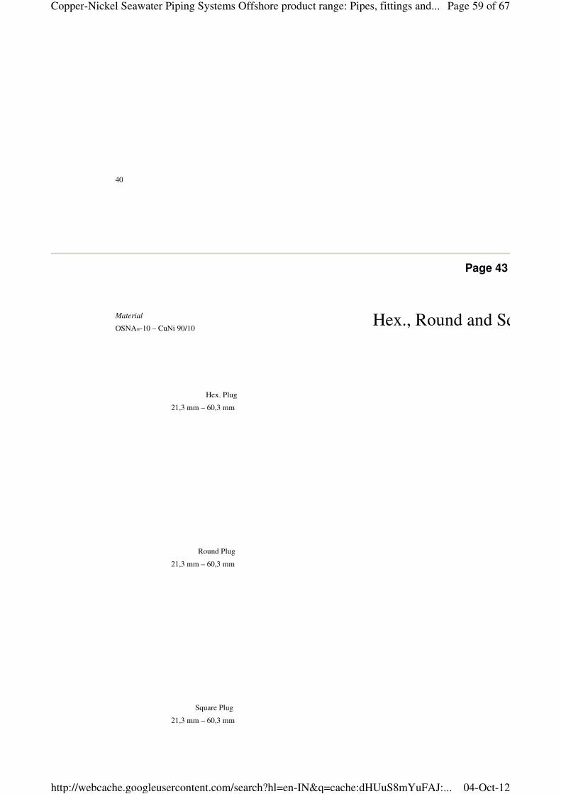
Page 43
Hex., Round and Square Head Plugs
Hex. Plug
21,3 mm – 60,3 mm
Round Plug
21,3 mm – 60,3 mm
Square Plug
21,3 mm – 60,3 mm
Material
OSNA®-10 – CuNi 90/10
Page 59 of 67Copper-Nickel Seawater Piping Systems Offshore product range: Pipes, fittings and...
04-Oct-12http://webcache.googleusercontent.com/search?hl=en-IN&q=cache:dHUuS8mYuFAJ:...
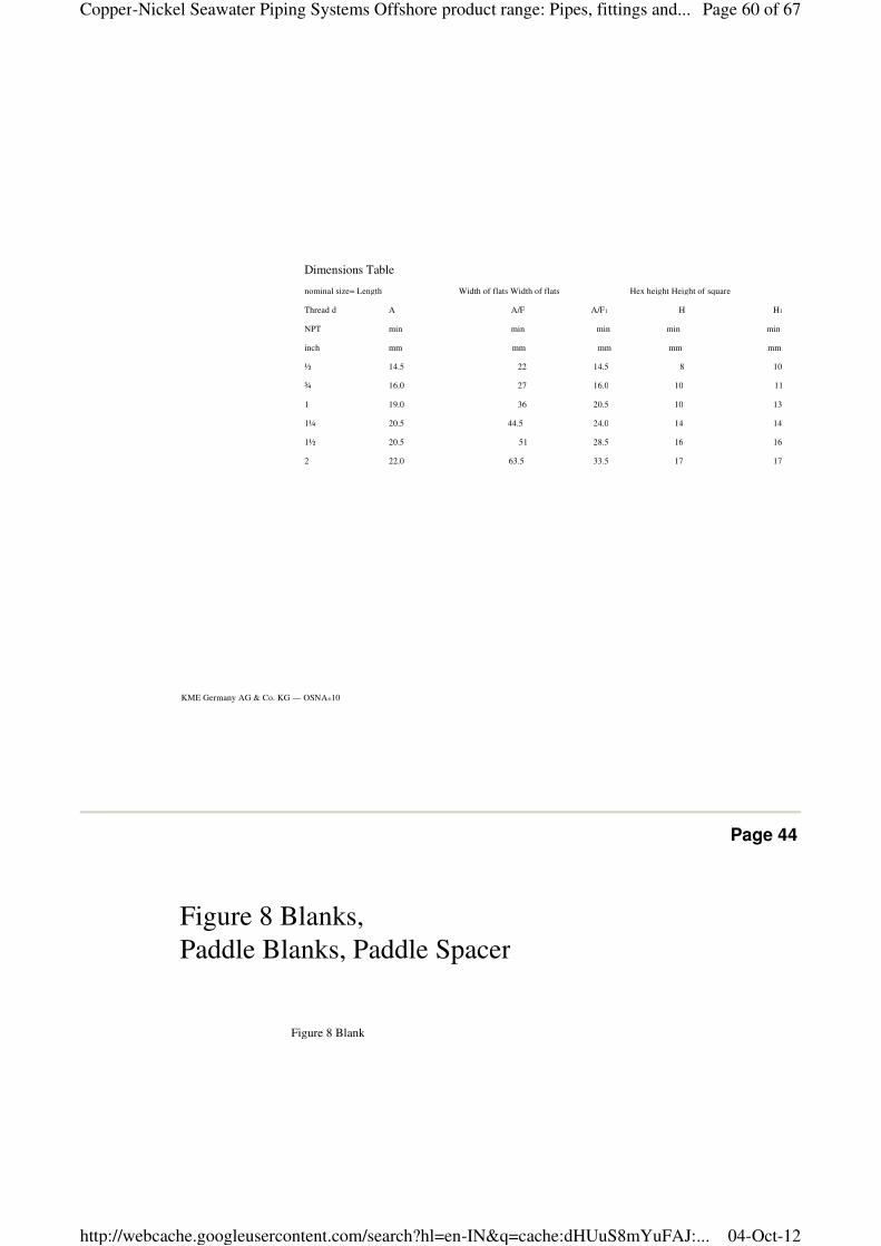
KME Germany AG & Co. KG — OSNA®10
Dimensions Table
nominal size= Length Width of flats Width of flats Hex height Height of square
Thread d A A/F A/F1 H H1
NPT min min min min min
inch mm mm mm mm mm
½ 14.5 22 14.5 8 10
¾ 16.0 27 16.0 10 11
1 19.0 36 20.5 10 13
1¼ 20.5 44.5 24.0 14 14
1½ 20.5 51 28.5 16 16
2 22.0 63.5 33.5 17 17
Page 44
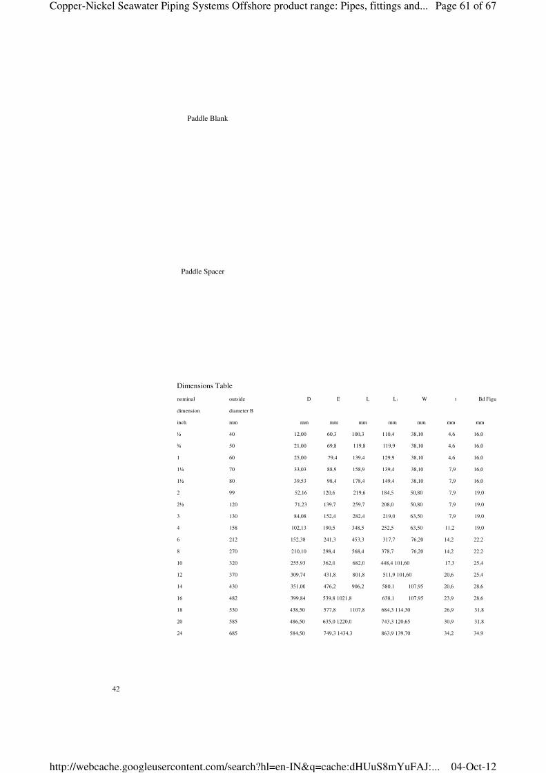
Figure 8 Blanks,
Paddle Blanks, Paddle Spacer
Figure 8 Blank
Page 60 of 67Copper-Nickel Seawater Piping Systems Offshore product range: Pipes, fittings and...
04-Oct-12http://webcache.googleusercontent.com/search?hl=en-IN&q=cache:dHUuS8mYuFAJ:...
42
Paddle Blank
Paddle Spacer
Dimensions Table
nominal outside D E L L1 W t Bd Figure 8 Blanks
dimension diameter B
inch mm mm mm mm mm mm mm mm
½ 40 12,00 60,3 100,3 110,4 38,10 4,6 16,0
¾ 50 21,00 69,8 119,8 119,9 38,10 4,6 16,0
1 60 25,00 79,4 139,4 129,9 38,10 4,6 16,0
1¼ 70 33,03 88,9 158,9 139,4 38,10 7,9 16,0
1½ 80 39,53 98,4 178,4 149,4 38,10 7,9 16,0
2 99 52,16 120,6 219,6 184,5 50,80 7,9 19,0
2½ 120 71,23 139,7 259,7 208,0 50,80 7,9 19,0
3 130 84,08 152,4 282,4 219,0 63,50 7,9 19,0
4 158 102,13 190,5 348,5 252,5 63,50 11,2 19,0
6 212 152,38 241,3 453,3 317,7 76,20 14,2 22,2
8 270 210,10 298,4 568,4 378,7 76,20 14,2 22,2
10 320 255,93 362,0 682,0 448,4 101,60 17,3 25,4
12 370 309,74 431,8 801,8 511,9 101,60 20,6 25,4
14 430 351,00 476,2 906,2 580,1 107,95 20,6 28,6
16 482 399,84 539,8 1021,8 638,1 107,95 23,9 28,6
18 530 438,50 577,8 1107,8 684,3 114,30 26,9 31,8
20 585 486,50 635,0 1220,0 743,3 120,65 30,9 31,8
24 685 584,50 749,3 1434,3 863,9 139,70 34,2 34,9
Page 61 of 67Copper-Nickel Seawater Piping Systems Offshore product range: Pipes, fittings and...
04-Oct-12http://webcache.googleusercontent.com/search?hl=en-IN&q=cache:dHUuS8mYuFAJ:...
Page 45
Material
OSNA®-10 – CuNi 90/10
Page 62 of 67Copper-Nickel Seawater Piping Systems Offshore product range: Pipes, fittings and...
04-Oct-12http://webcache.googleusercontent.com/search?hl=en-IN&q=cache:dHUuS8mYuFAJ:...
KME Germany AG & Co. KG — OSNA®10
Page 46
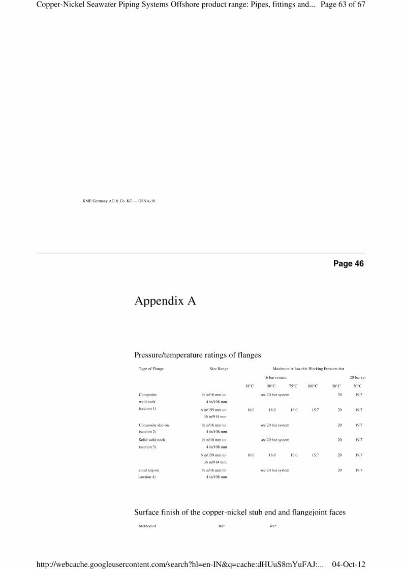
Appendix A
Type of Flange Size Range Maximum Allowable Working Pressure-bar
16 bar system 20 bar system
38°C 50°C 75°C 100°C 38°C 50°C
Composite
weld neck
(section 1)
½ in/16 mm to
4 in/108 mm
see 20 bar system 20 19.7
6 in/159 mm to
36 in/914 mm
16.0 16.0 16.0 15.7 20 19.7
Composite slip-on
(section 2)
½ in/16 mm to
4 in/108 mm
see 20 bar system 20 19.7
Solid weld neck
(section 3)
½ in/16 mm to
4 in/108 mm
see 20 bar system 20 19.7
6 in/159 mm to
36 in/914 mm
16.0 16.0 16.0 15.7 20 19.7
Solid slip-on
(section 4)
½ in/16 mm to
4 in/108 mm
see 20 bar system 20 19.7
Pressure/temperature ratings of flanges
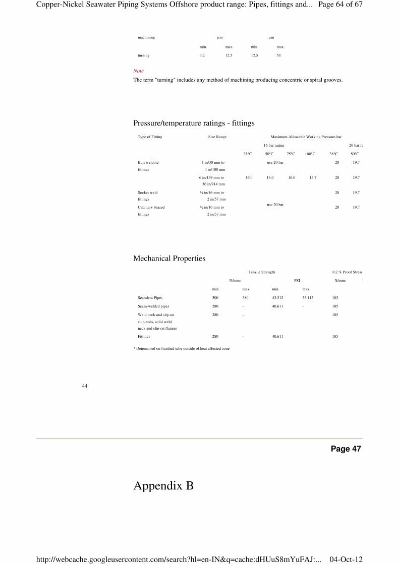
Method of
machining
Ra*
µm
Rz*
µm
Surface finish of the copper-nickel stub end and flangejoint faces
Page 63 of 67Copper-Nickel Seawater Piping Systems Offshore product range: Pipes, fittings and...
04-Oct-12http://webcache.googleusercontent.com/search?hl=en-IN&q=cache:dHUuS8mYuFAJ:...
44
Tensile Strength 0.2 % Proof Stress
N/mm2 PSI N/mm2 PSI
min. max. min. max.
Seamless Pipes 300 380 43.512 55.115 105 15.229
Seam-welded pipes 280 - 40.611 - 105 15.229
Weld neck and slip-on
stub ends, solid weld
neck and slip-on flanges
280 - 105 15.229
Fittings 280 - 40.611 105 15.229
* Determined on finished tube outside of heat affected zone
Mechanical Properties
Type of Fitting Size Range Maximum Allowable Working Pressure-bar
16 bar rating 20 bar rating
38°C 50°C 75°C 100°C 38°C 50°C
Butt welding
fittings
1 in/30 mm to
4 in/108 mm
use 20 bar 20 19.7
6 in/159 mm to
36 in/914 mm
16.0 16.0 16.0 15.7 20 19.7
Socket weld
fittings
½ in/16 mm to
2 in/57 mm
use 20 bar
20 19.7
Capillary brazed
fittings
½ in/16 mm to
2 in/57 mm
20 19.7
Pressure/temperature ratings - fittings
machining µm µm
min. max. min. max.
turning 3.2 12.5 12.5 50
Note
The term "turning" includes any method of machining producing concentric or spiral grooves.
Page 47
Appendix B
Page 64 of 67Copper-Nickel Seawater Piping Systems Offshore product range: Pipes, fittings and...
04-Oct-12http://webcache.googleusercontent.com/search?hl=en-IN&q=cache:dHUuS8mYuFAJ:...
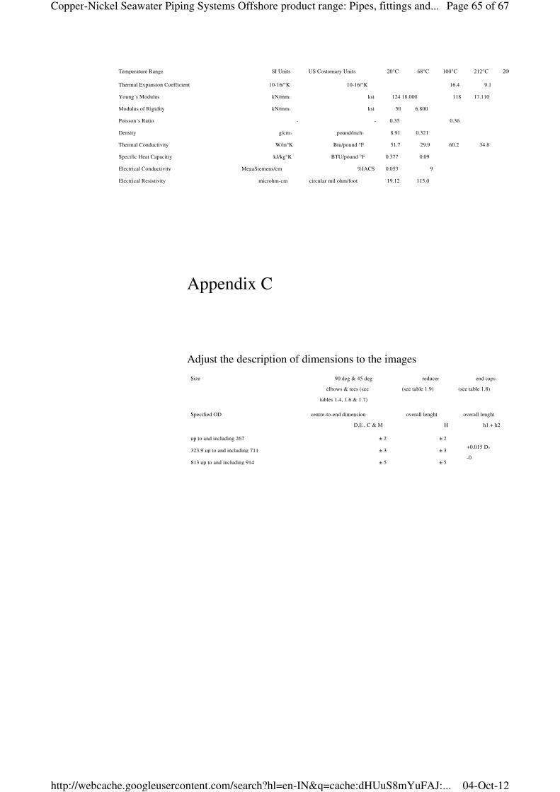
Temperature Range SI Units US Costomary Units 20°C 68°C 100°C 212°C 200°C
Thermal Expansion Coefficient 10-16/°K 10-16/°K 16.4 9.1
Young´s Modulus kN/mm2 ksi 124 18.000 118 17.110
Modulus of Rigidity kN/mm2 ksi 50 6.800
Poisson´s Ratio - - 0.35 0.36
Density g/cm3 pound/inch3 8.91 0.321
Thermal Conductivity W/m°K Btu/pound °F 51.7 29.9 60.2 34.8
Specific Heat Capacitiy kJ/kg°K BTU/pound °F 0.377 0.09
Electrical Conductivity MegaSiemens/cm %IACS 0.053 9
Electrical Resistivity microhm-cm circular mil ohm/foot 19.12 115.0
Appendix C
Size 90 deg & 45 deg
elbows & tees (see
tables 1.4, 1.6 & 1.7)
reducer
(see table 1.9)
end caps
(see table 1.8)
Specified OD centre-to-end dimension
D,E , C & M
overall lenght
H
overall lenght
h1 + h2
up to and including 267 ± 2 ± 2
+0.015 D0
-0
323.9 up to and including 711 ± 3 ± 3
813 up to and including 914 ± 5 ± 5
Adjust the description of dimensions to the images
Page 65 of 67Copper-Nickel Seawater Piping Systems Offshore product range: Pipes, fittings and...
04-Oct-12http://webcache.googleusercontent.com/search?hl=en-IN&q=cache:dHUuS8mYuFAJ:...
KME Germany AG & Co. KG — OSNA®10
Page 48
KME Germany AG & Co. KG
Marine Applications
P.O. Box 3320
49023 OSNABRмCK
Klosterstraпe 29
49074 OSNABRмCK
GERMANY
Fon +49 541 321-3011
Fax +49 541 321-3020
www.marine-applications.com
Page 66 of 67Copper-Nickel Seawater Piping Systems Offshore product range: Pipes, fittings and...
04-Oct-12http://webcache.googleusercontent.com/search?hl=en-IN&q=cache:dHUuS8mYuFAJ:...
® = registered trademark
All changes reserved.
Owing to limitations in printing technology, the colours reproduced in this brochure should be regarded as approximate equivalents to the colours described.
0511.005.0108
Page 67 of 67Copper-Nickel Seawater Piping Systems Offshore product range: Pipes, fittings and...
04-Oct-12http://webcache.googleusercontent.com/search?hl=en-IN&q=cache:dHUuS8mYuFAJ:...


