
www.ecodense.com
CONDENSING BOILER INSTALLATION, OPERATING AND MAINTENANCE MANUAL
ECODENSE WT 65 ECODENSE WT 80 ECODENSE WT 100 ECODENSE WT 115 ECODENSE WT 125 ECODENSE WT 150

20.12.2017 Rev. 07 1
DEAR USER,
The Condensing Boilers ECODENSE WT 65, ECODENSE WT 80, ECODENSE WT 100, ECODENSE WT 115, ECODENSE WT 125, ECODENSE WT 150 are constructed and manufactured according to the most advance technological inventions and the safety rules. It is easy to use for our customers.
We recommend that you read this manual and safety warnings thoroughly before the use of the device in order to ensure safe, cost effective and environmental-friendly use.
If you encounter any issue that is not explained clearly in this manual or you could
not understand, please contact with our service department. We thank you for choosing ECODENSE brand.
This Operating Manual is an integral part of the device and must be maintained in a plastic dossier and hung at a clearly visible place by the device.
TERMO ISI SİSTEMLERİ SAN.VE TİC.A.Ş.
Esentepe Mah.Milangaz Cad. No:75 K:3 Kartal Monumento Plaza
Kartal/İSTANBUL/TÜRKİYE Tel: +90 216 442 93 00 Fax: +90 216 370 45 03
www.ecodense.com e-mail:[email protected]

20.12.2017 Rev. 07 2
CONTENTS WARNINGS ............................................................................................................................................... 3
Warning Symbols and Descriptions ........................................................................................................ 3 General Safety Rules .............................................................................................................................. 4
TERMS OF WARRANTY ......................................................................................................................... 5 Out of Warranty Conditions .................................................................................................................... 5
GENERAL CHARACTERISTICS OF CONDENSING BOILER ............................................................. 6 Usage of CASCADE .............................................................................................................................. 6 ECODENSE Components ..................................................................................................................... 7
CIRCUIT SCHEMES ................................................................................................................................. 9 CLOSED CIRCUIT COMPONENTS ...................................................................................................... 17
Balance Tank ........................................................................................................................................ 17 Sizing Table For Expansion Tank ......................................................................................................... 18 Expansion Tank .................................................................................................................................... 19 Manometer ............................................................................................................................................ 19 Strainer ................................................................................................................................................. 19 Air Separator ......................................................................................................................................... 19
WATER QUALITY ................................................................................................................................. 20 TECHNICAL DATA ................................................................................................................................ 21
Capacity Table ...................................................................................................................................... 21 Condensing Boiler Dimensions ............................................................................................................ 22 Noise Level ........................................................................................................................................... 22
CONDENSING BOİLER HANDLING INFORMATION ....................................................................... 23 INSTALLATION ..................................................................................................................................... 24
General Controls ................................................................................................................................... 24 STACK CONNECTIONS ........................................................................................................................ 25 ASSEMBLY ............................................................................................................................................. 27
ECODENSE Assembly Instructions ..................................................................................................... 27 ECODENSE Single/CASCADE Assembly Instructions ....................................................................... 27 Assembly of Condensing Fluid Drain ................................................................................................... 28
ECODENSE CONTROL INSTRUCTIONS BEFORE START-UP ........................................................ 29 ELECTRICAL DIAGRAM ...................................................................................................................... 30 COMMISSIONING .................................................................................................................................. 31
Before Commissioning ......................................................................................................................... 31 Checks During Commissioning ............................................................................................................ 32
ADJUSTING COMBUSTIN PARAMATERS ......................................................................................... 32 Adjustment and Measurement Points .................................................................................................... 32 Adjusting Minimum Capacity ............................................................................................................... 33 Adjusting Medium Capacity ................................................................................................................. 33 Adjusting Maximum Capacity .............................................................................................................. 34 Adjsuting Time Schedule ...................................................................................................................... 34
MAINTENANCE ..................................................................................................................................... 35 Monthly Maintenance ........................................................................................................................... 35 Seasonal Maintenance ........................................................................................................................... 35
LIST OF ERROR CODE .......................................................................................................................... 36 SOLUTION RECOMMENDATIONS FOR SOME OF THE PROBLEMS ............................................ 40 AFTER SALES SERVICES ..................................................................................................................... 41 NOTES ..................................................................................................................................................... 42

20.12.2017 Rev. 07 3
WARNINGS Warning Symbols and Descriptions
Symbols Symbol Descriptions
Important information and useful hints.
Warning of danger to life or property.
Warning of electrical voltage.
Product handling information.
GAZ HATTINI TEMİZLEYİNİZ. CLEAN GAS LINE. ЧИСТАЯ ЛИНИЯ ГАЗ.
"Clean the gas line" warning on gas line.
Carry in an upright position. Fragile Item. Protect against water.

20.12.2017 Rev. 07 4
General Safety Rules
• All personnel engaged in installation, disassembly, commissioning, operation, control,
maintenance and repair should have received the necessary training and fully read and understood this manual.
• No changes that might damage the safety of the device must be made by persons and/or organizations on the device.
• All operation, commissioning and installation works (except for burning adjustment) should be carried out when the device is not operating and after disconnecting the power supply. Noncompliance with these rules may lead to serious bodily injuries and even death by electrical shocks or uncontrolled flame formation.
• Repairs concerned with safety elements should be carried out only by the manufacturing company. • The device should never be used by children, mentally handicapped and inexperienced persons. • Children must not be allowed to play with the device. • Keep the device away from explosive and flammable materials. • Device must intake air, and ventilation and air discharge holes must not be closed.
If you sense gas leakage;
• Shut down valves of all gas devices. • Open all doors and windows. • Do not turn on electric devices or do not turn them off if they are working. • Do not use burner derived tools such as match and lighter. • Inform the gas company.
Do not store any inflammable materials in boiler room.
Wear hearing protectors if there is noise in boiler room.
In case of fıre or other emergency;
● Switch off the main switch ● Close the main fuel shut-off valve outside the plant. ● Take appropriate actions
20.12.2017 Rev. 07 5
TERMS OF WARRANTY
Main and auxiliary equipment and all components used in ECODENSE WT 65, ECODENSE WT 80, ECODENSE WT 100, ECODENSE WT 115, ECODENSE WT 125, ECODENSE WT 150 Condensing Boilers are guaranteed for 1 year by TERMO ISI SİSTEMLERİ A.Ş. starting from the date of commissioning under the maintenance, adjustment, operating conditions and relevant mechanic, chemical and thermal effects explained herein.
Please note that this warranty is only valid if the device(s) is commissioned and maintained by our authorized services.
Our company reserves the right to make any modifications on the product and all instructions thereof for improvement purposes.
Out of Warranty Conditions
• Any damage arising out of or in relation to customers’ non-compliance to their responsibilities with regards to installation, commissioning, operation and maintenance,
• Any damage arising out of or in relation to commissioning, repairs and maintenance carried out by unauthorized services,
• Any damage that may occur during transportation or storage of the product, • Not preserving the product in its original packaging until the installation stage, • Incorrect and poor electrical connections, Failures due to incorrect voltage applications, frequent
repetition of voltage fluctuations, • Any damage that may occur as a result of incorrect fuel usage or, foreign substances in the fuel
used or using of the product without any fuel, • Any damage that may occur due to foreign particles entered into the product during installation
and operation, • Failures due to incorrect device selection, • Any damage to unit due to natural disasters, • Devices without any warranty certificates, • Warranty Certificates without the stamp and signature of the authorized dealer or service, • Devices with any falsification on the warranty certificate or without an original serial number. • The risks during transportation of device under the responsibility of customer belong to the
customer. • Presence of misuse faults are indicated in the reports issued by authorized service stations or our
authorized agent, dealer, representative or our factory in case of unavailability of authorized service stations.
• Customers may apply consumer protection arbitrator committee with regards to this report and request for an expert report.

20.12.2017 Rev. 07 6
GENERAL CHARACTERISTICS OF CONDENSING BOILER
ECODENSE WT 65, ECODENSE WT 80, ECODENSE WT 100, ECODENSE WT 115, ECODENSE WT 125, ECODENSE WT 150 are heating devices operating with natural gas or LPG with a very low suction power, and equipped with high-duty, premix condensing control system with micro-processor. The boiler is composed of a heat exchanger with aluminum cooling fins and a steel premix burner equipped with ignition and ionization flame control, modulating fan and gas valve. ECODENSE WT 65, ECODENSE WT 80, ECODENSE WT 100, ECODENSE WT 115, ECODENSE WT 125, ECODENSE WT 150 are designed for use as standalone as well as cascade.
The structure of cascade to be formed by the product group increases the usability in collective housing and individual building applications with its efficient composition.
Usage of CASCADE
Premix condensing technology is used in ECODENSE WT 65, ECODENSE WT 80, ECODENSE WT 100, ECODENSE WT 115, ECODENSE WT 125, ECODENSE WT 150 wall type condensing boilers in order to reach higher efficiency and energy-saving. With suitable connections and approval from gas distribution companies, ECODENSE WT 65, ECODENSE WT 80, ECODENSE WT 100, ECODENSE WT 115, ECODENSE WT 125, ECODENSE WT 150 boilers can be connected as much as required capacity. Maximum operation pressure of these boilers is 4 bar (6 bar for specific applications). Circulation pump, expansion tank and safety valve are not present in these boilers. These are required to be provided by customer and are mandatory to use.

20.12.2017 Rev. 07 7
ECODENSE Components ECODENSE WT 65 – ECODENSE WT 80
No. Material 1 Venturi 13 Reset
2 Flue outlet 14 Control card 3 Gas valve 15 Boiler body 4 Ignition transformer 16 Heater circuit return 5 Ignition electrode 17 Heater circuit supply 6 Fan 18 Ionization electrode 7 Automatic air relief cock 19 Condensing water release outlet 8 Water pressure sensor 20 Condensing water trap 9 Water flow sensor 21 Gas inlet 10 Condensing water collection tray 22 Burner 11 Control panel 23 Bulls eye 12 Start/Stop

20.12.2017 Rev. 07 8
ECODENSE WT 100 – ECODENSE WT 115 - ECODENSE WT 125- ECODENSE WT 150
No. Material 1 Venturi 13 Reset
2 Flue outlet 14 Control card 3 Gas valve 15 Boiler body 4 Ignition transformer 16 Heater circuit return 5 Ignition electrode 17 Heater circuit supply 6 Fan 18 Ionization electrode 7 Automatic air relief cock 19 Condensing water release outlet 8 Water pressure sensor 20 Condensing water trap 9 Water flow sensor 21 Gas inlet 10 Condensing water collection tray 22 Burner 11 Control panel 23 Bulls eye 12 Start/Stop

20.12.2017 Rev. 07 9
CIRCUIT SCHEMES

20.12.2017 Rev. 07 10

20.12.2017 Rev. 07 11

20.12.2017 Rev. 07 12

20.12.2017 Rev. 07 13

20.12.2017 Rev. 07 14

20.12.2017 Rev. 07 15

20.12.2017 Rev. 07 16
20.12.2017 Rev. 07 17
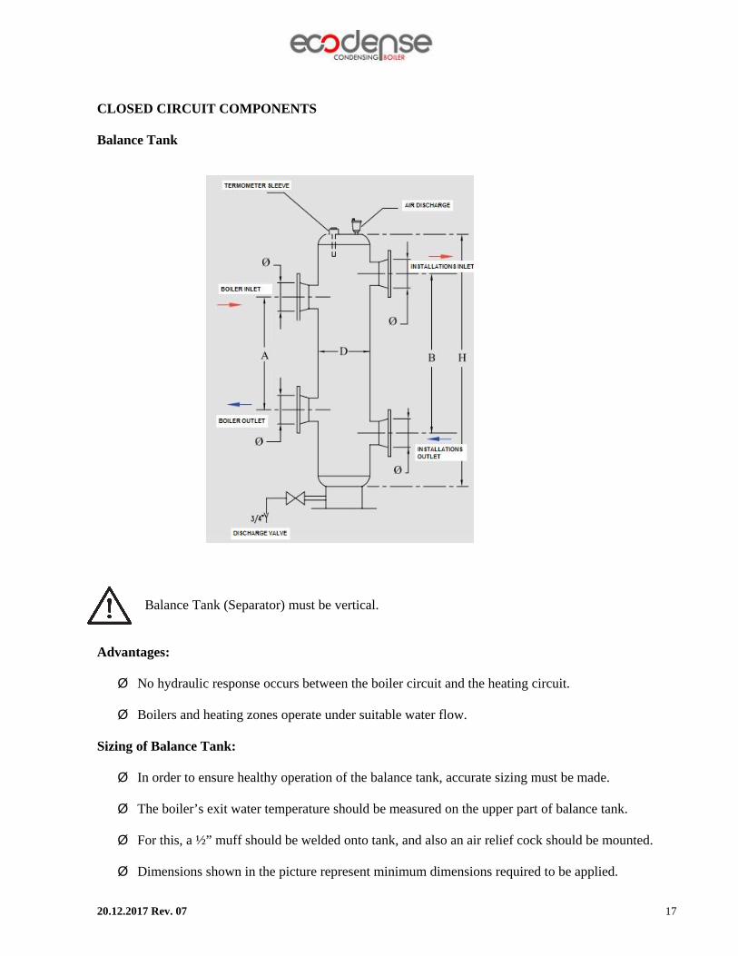
CLOSED CIRCUIT COMPONENTS Balance Tank Balance Tank (Separator) must be vertical. Advantages: Ø No hydraulic response occurs between the boiler circuit and the heating circuit.
Ø Boilers and heating zones operate under suitable water flow.
Sizing of Balance Tank: Ø In order to ensure healthy operation of the balance tank, accurate sizing must be made.
Ø The boiler’s exit water temperature should be measured on the upper part of balance tank.
Ø For this, a ½” muff should be welded onto tank, and also an air relief cock should be mounted.
Ø Dimensions shown in the picture represent minimum dimensions required to be applied.

20.12.2017 Rev. 07 18
Sizing Table For Expansion Tank
SYSTEM CAPACITY A B H
EXPANSION TANK
DIAMETER(D)
INLET & OUTLET
DIAMETER(Ø)
kw cm cm cm mm mm 65 33 38 48 100 50 90 38 44 55 125 50 115 42 47 59 125 50 130 47 54 68 150 65 170 54 62 77 150 65 230 59 67 84 200 80 345 72 82 103 200 80 460 83 95 119 250 100 575 93 106 133 250 100 690 102 116 145 300 125 805 110 126 157 300 125 920 118 134 168 350 150 1035 131 150 188 350 150 1150 138 157 197 400 200 1265 144 164 206 400 200 1380 150 171 214 450 200 1495 155 178 222 450 200 1610 162 185 230 450 200 1725 169 192 238 450 200

20.12.2017 Rev. 07 19
Expansion Tank
Expansion tank fore pressures must be adjusted according to system. Expansion tank should be placed parallel to circuit return line.
Manometer A manometer with capacity of at least 0 to 6 bar must be connected to system. Manometer should be placed to easily visible spot from filling point, preferably same point as expansion tank.
Strainer Any dirt or residue in circuit water causes damage got boiler and circuit components and decreases efficiency by reducing heat transfer. In order to prevent this problem a strainer must be connected to circuit.
Air Separator The air in the water dissolves due to increasing temperature and flow in the circuit. Dissolved air causes cavitation, sound and efficiency loss. By using an air separator air is removed from the system. The hydraulic system design must comply with the circuit diagrams specified in the user manual to ensure that the system operates smoothly and that installation errors do not result in loss of efficiency. The hydraulic system must have a balance vessel, sediment trap, air separator and expansion tank in accordance with the system capacity and specifications.

20.12.2017 Rev. 07 20
WATER QUALITY
1. Before connection of condensing boilers any dirt and residue in circuit must be cleaned.
2. Refined water must be used while adding water to heating circuit due to any loss in closed circuit.
3. Permitted water hardness for water used in water circuit must comply with VDI 2035 standard. The lime dissolved in water, settles on hot surfaces and forms an insulation layer when water temperature rises. This prevents heat transfer and high temperature might damage the heat exchanger. If boiler water cycles through water circuit, all circuit water must meet above requirements. If a plate heat exchanger separates boiler water and heating circuit water, only the water between boiler and heat exchanger must meet these requirements. In order to prevent calcification, properties of water in circuit and water added must be as below:
Type Boiler Capacity Total Water Hardness (°F)
Single 50-200 kW <20 Single 200-600 kW <15 Single >600 kW <0,2 Cascade All capacities <0,2
*Volume to capacity ratio of water in circuit must be higher than 20l/kW. Total volume of first filled water and additional water must be less than volume of system.
Note: pH value of unrefined water must be 7<pH<9. This pH value can be achieved after filling the circuit with main circuit water with pH value of 7 and air separation. pH value of refined water must be between 7-8,5 pH.
20.12.2017 Rev. 07 21
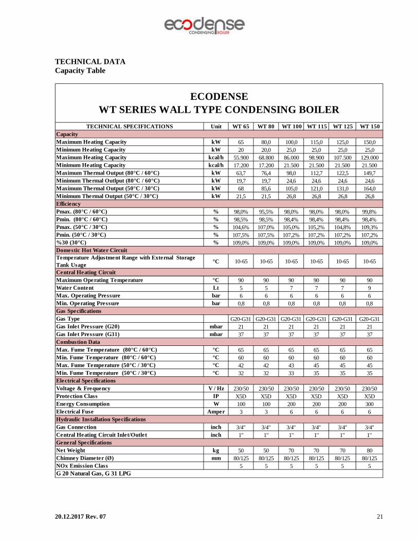
TECHNICAL DATA Capacity Table
Unit WT 65 WT 80 WT 100 WT 115 WT 125 WT 150
kW 65 80,0 100,0 115,0 125,0 150,0kW 20 20,0 25,0 25,0 25,0 25,0
kcal/h 55.900 68.800 86.000 98.900 107.500 129.000kcal/h 17.200 17.200 21.500 21.500 21.500 21.500
kW 63,7 76,4 98,0 112,7 122,5 149,7kW 19,7 19,7 24,6 24,6 24,6 24,6kW 68 85,6 105,0 121,0 131,0 164,0kW 21,5 21,5 26,8 26,8 26,8 26,8
% 98,0% 95,5% 98,0% 98,0% 98,0% 99,8%% 98,5% 98,5% 98,4% 98,4% 98,4% 98,4%% 104,6% 107,0% 105,0% 105,2% 104,8% 109,3%% 107,5% 107,5% 107,2% 107,2% 107,2% 107,2%% 109,0% 109,0% 109,0% 109,0% 109,0% 109,0%
°C 10-65 10-65 10-65 10-65 10-65 10-65
°C 90 90 90 90 90 90Lt 5 5 7 7 7 9bar 6 6 6 6 6 6bar 0,8 0,8 0,8 0,8 0,8 0,8
G20-G31 G20-G31 G20-G31 G20-G31 G20-G31 G20-G31mbar 21 21 21 21 21 21mbar 37 37 37 37 37 37
°C 65 65 65 65 65 65°C 60 60 60 60 60 60°C 42 42 43 45 45 45°C 32 32 33 35 35 35
V / Hz 230/50 230/50 230/50 230/50 230/50 230/50IP X5D X5D X5D X5D X5D X5DW 100 100 200 200 200 300
Amper 3 3 6 6 6 6
inch 3/4'' 3/4'' 3/4'' 3/4'' 3/4'' 3/4''inch 1'' 1'' 1'' 1'' 1'' 1''
kg 50 50 70 70 70 80mm 80/125 80/125 80/125 80/125 80/125 80/125
5 5 5 5 5 5
Maximum Thermal Output (80°C / 60°C)
ECODENSE WT SERIES WALL TYPE CONDENSING BOILER
TECHNICAL SPECIFICATIONSCapacityMaximum Heating CapacityMinimum Heating CapacityMaximum Heating CapacityMinimum Heating Capacity
Water ContentMax. Operating PressureMin. Operating PressureGas Specifications
Minimum Thermal Outlput (80°C / 60°C)Maximum Thermal Output (50°C / 30°C)Minimum Thermal Output (50°C / 30°C)Efficiency
%30 (30°C)Domestic Hot Water Circuit
Central Heating CircuitMaximum Operating Temperature
Temperature Adjustment Range with External Storage Tank Usage
Gas Type
Energy ConsumptionElectrical Fuse
Gas Inlet Pressure (G20)Gas Inlet Pressure (G31)Combustion DataMax. Fume Temperature (80°C / 60°C)Min. Fume Temperature (80°C / 60°C)Max. Fume Temperature (50°C / 30°C)
Chimney Diameter (Ø)NOx Emission ClassG 20 Natural Gas, G 31 LPG
Pmax. (80°C / 60°C)Pmin. (80°C / 60°C)Pmax. (50°C / 30°C)Pmin. (50°C / 30°C)
Hydraulic Installation SpecificationsGas ConnectionCentral Heating Circuit Inlet/OutletGeneral SpecificationsNet Weight
Min. Fume Temperature (50°C / 30°C)Electrical SpecificationsVoltage & FrequencyProtection Class

20.12.2017 Rev. 07 22
Condensing Boiler Dimensions
Noise Level
When the condensing boiler is in operation, the maximum noise level released is <70 dBA. The noise level value corresponds to the value measured with semi-anekoik (semi-unreflecting acoustic) room testing according to the product standards at the time of expansion of the smoke release system, when the condensing boiler operates at the maximum heating power.
20.12.2017 Rev. 07 23
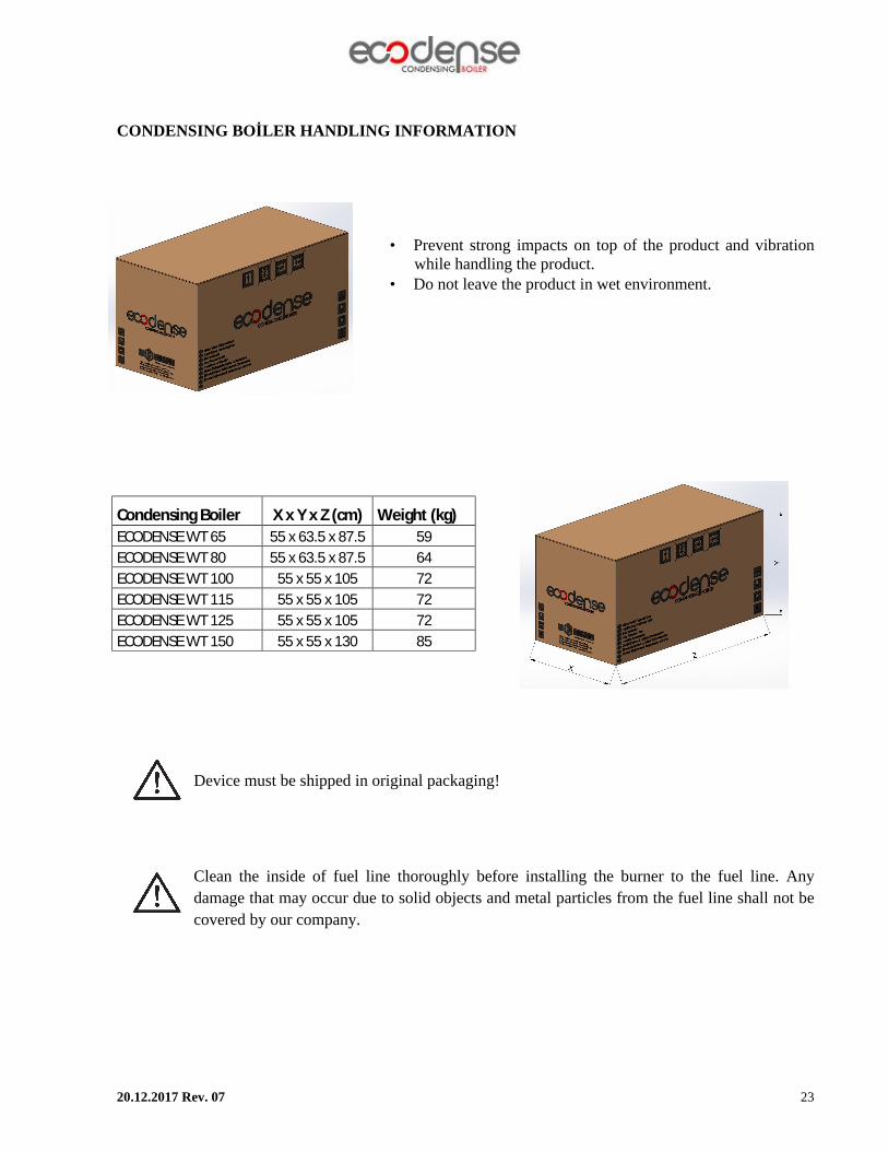
CONDENSING BOİLER HANDLING INFORMATION
• Prevent strong impacts on top of the product and vibration while handling the product.
• Do not leave the product in wet environment.
Device must be shipped in original packaging!
Clean the inside of fuel line thoroughly before installing the burner to the fuel line. Any damage that may occur due to solid objects and metal particles from the fuel line shall not be covered by our company.
Condensing Boiler X x Y x Z (cm) Weight (kg) ECODENSE WT 65 55 x 63.5 x 87.5 59 ECODENSE WT 80 55 x 63.5 x 87.5 64 ECODENSE WT 100 55 x 55 x 105 72 ECODENSE WT 115 55 x 55 x 105 72 ECODENSE WT 125 55 x 55 x 105 72 ECODENSE WT 150 55 x 55 x 130 85

20.12.2017 Rev. 07 24
INSTALLATION General Controls Ø The heating capacity of the device should be determined based on the heat requirement calculated.
Ø All parts necessary for the system must be available. Ø Make sure that all protection and safety devices are available. Ø In order to prevent accumulation of dirt in the system, prevention of boiler operation and damage
given to the boiler by clogging, a filter must be mounted onto the system’s return pipe. Ø The device has a frost protection system to prevent the device from freezing when the water
temperature of the installation falls below +4 ˚C. Ø Ensure that the gas connections are made with pipes confirming to the standards, and that there is
no leakage on these connections. Ø Ensure that the electric connections are proper.
During cascade installation, do not forget to mount an external gas cut-off valve suitable to the devices.
Electrical Connection
Perform electrical connections according to the diagram provided. Follow general security rules during installation of electric wiring and making connections. Connect the earthing terminal in electric panel to the earthing installation.
External Outdoor Sensor (Optional):
Connect the sensor to the relevant terminal. The length of electric cable for external sensor
connection is max. 25 m. A 2x1.5 cable should be used. The sensor must not be exposed to the morning sun and if possible, to direct sunlight. Since the values to be read by the sensor will be affected, it must not be mounted close to any window, door, vent hole and heat sources.
Unsuitable places to mount external sensor:

20.12.2017 Rev. 07 25
STACK CONNECTIONS
1. Horizontal stack extensions must be connected to boiler at 1.5°-3° angle in order to drain condensing fluid.
2. Stack connections must be leak proof. Some examples of stack setup can be seen below:
B23=Flue gas evacuation is achieved with a flue gas duct between the boiler room and the outside. Combustion air is sucked from the boiler room. C13=A horizontal concentric air/flue gas duct is used for flue gas evacuation and suction of combustion air. C33=A vertical concentric air/flue gas duct is used for flue gas evacuation and suction of combustion air.

20.12.2017 Rev. 07 26
Ducts should be installed according to local ventilation conditions.
Anything which can be affected from flue gas like living beings, food, etc., should not be present near the duct outlet. Components used in duct installation must comply with EN-1856-1 “Chimneys - Requirements for metal chimneys - Part 1: System chimney products” standard.
Outlet and inlet diameter table for B23-C13-C33 type ducts:
DUCT TYPE WT-65 WT-80 WT-100 WT-115 WT-125 WT-150
Flue Gas Outlet Diameter (mm) 80 80 80 80 80 80
Combustion Air Inlet Diameter(mm) 60 60 60 60 60 60
Flue Gas Outlet Diameter (mm) 80 80 80 80 80 -
Combustion Air Inlet Diameter(mm) 125 125 125 125 125 -
B23
C13-C33
Table for maximum permissible lengths and reductions in length for C13-C33 type flue gas duct sets:
WT-65 WT-80 WT-100 WT-115 WT-125
Duct Diameter (mm) 80/125 80/125 80/125 80/125 80/125
Max. Permissible Length (m) 4 4 2 2 245° Elbow, Reduction on Max. Permissible Length (m)
0.25 0.25 0.25 0.25 0.25
90° Elbow, Reduction on Max. Permissible Length (m)
0.5 0.5 0.5 0.5 0.5
Maximum permissible length should be reduced by the values in the table according to their type for each elbow used.
Maximum permissible length for B23 type flue gas ducts is 20 m.
Following accessories must be used for the concentric flue part connections: 1. Concentric Adaptor from Ø80/80 to Ø80/125 2. Ø60 to Ø80 adaptor 3. Ø60 Air suction elbow

20.12.2017 Rev. 07 27
ASSEMBLY ECODENSE Assembly Instructions
ECODENSE condensing boilers are designed to work as CASCADE; they are compatible for side
by side or back to back operation. They provide suitable space utilization for every stokehold design at required capacities. ECODENSE Single/CASCADE Assembly Instructions
1. Mount the boiler to wall by using assembly equipment shipped with your boiler. 200 mm of gap between boilers is advised.
2. Anchor the hangers to designated wall by using anchor plugs and screws shipped with your boiler as shown below.
3. In order to mount the boiler to wall, lift the boiler above the level of hangers and ensure that boiler is solidly mounted on the hangers.
4. Control the robustness of hanged boilers.
There must be at least 200 mm of gap between adjacent boilers and at least 600 mm of space in front of the boiler for ease of service.

20.12.2017 Rev. 07 28
Assembly of Condensing Fluid Drain
1. Ensure that siphon is fully filled with water before activation of boiler.
2. Drain direction must allow flow of condensing fluid. Drain pipe must be planned to prevent any clogging due to external effect like frost, etc. Drain parts must be plastic.
3. Boiler condensing outlet must be at least 19mm.
Condensing drain must not be changed or clogged after assembly. Clogging of condensing drain causes the boiler to automatically shut down or causes the siphon to overflow. It will be helpful to pour some hot water to the open parts of drain if there is a possibility of frost. Drain must be open at all times to ensure proper functioning of the boiler.

20.12.2017 Rev. 07 29
ECODENSE CONTROL INSTRUCTIONS BEFORE START-UP
1. Ensure that boilers are mounted on fixed, firm and robust wall. Use metal hangers on improper
walls. 2. Ensure that every boiler has connected to their own 6A fuse. 3. Closed circuit maximum operation pressure is 3 bars. Ensure that in CASCADE SYSTEMS,
hydraulic separator is used below 3 bars and plate heat exchanger is used above 3 bars. In situation where plate heat exchanger is used, hydraulic separators with suitable capacities must be used at both sides.
4. In single or CASCADE applications, safety valve fixed to 3 bars must be used. Adjustable safety valve must not be used.
5. Control the sufficiency of capacity of circulation pump used in primer circuit (between boiler and hydraulic separator).
6. Ensure that stack connections in single or CASCADE, are at right radius and connected as leak proof.
7. Control air purger, air separator and strainer are used in the system and connected according to advised scheme.
8. A manometer to monitor system pressure must be present in system, control if it is mounted on the system.
9. Control if the condensing fluid siphon is made of plastic, isolated against frost, at correct radius and connected to condensing fluid drain with an angle. It should not be connected to rain drain.
10. Ensure that circuit and system are tested against leakage and systempressure is sufficient. 11. Ensure that gas pressure complies with boiler operation instructions. In situations where gas
pressure is higher than required pressure, a regulator must be used. 12. Ensure that sensors on boiler feed and circuit (outgoing-return temperature, ambient temperature,
boiler temperature sensors) are wired correctly. Wires of boiler feed and other equipment on circuit belong to user.
On first start-up if there is deficiency in the system detected by ECODENSE authorized service technicians, technicians are not allowed to activate the system.
Do not connect the circulation pump as the engine will be above and the engine will be below.
20.12.2017 Rev. 07 30
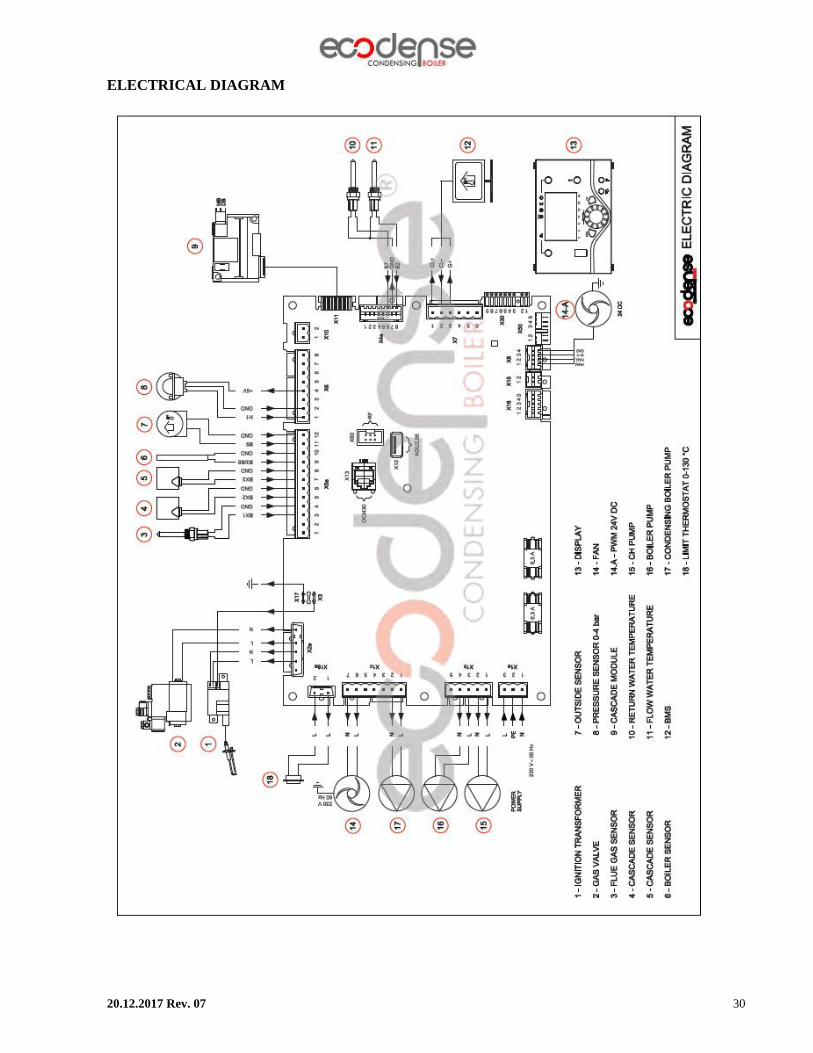
ELECTRICAL DIAGRAM

20.12.2017 Rev. 07 31
COMMISSIONING Before Commissioning Ø Open all open/closed valves between the device and systems. Ø Check gas connections by using foam and water solution for determining leakages on connections
carefully. Ø Check the initial pressure of expansion tank. Ø Fill the water system. Ø You should check that air separator works and cap of automatic air discharge is open while the gas
valve is closed. Ø First adjust the plumbing pressure proper value (1-3 bar is advised), hold the Manual
Mode button down for 5 sec. The deaeration function will be active on the screen. When this function is active, observe that the boiler is performing the aeration process.The circulation pump will circulate the water and air in the system will be purged from automatic air separator.The boiler will start deaerating and this will continue for 10-15 minutes
Ø Remove the air in radiators. Ø Check the air in the system after removing air form radiators.
If there is air in the system repeat the deaeration process.
Ø Check if the system pressure is over 1 bar. If it is under 1 bar there will be a warning on the screen. If it is under 0.5 bars, system will give an error code (118). In this case check the system pressure and air in the system (If plumbing pressure drops often do not start the boiler without determining the cause and call an authorized service).
Ø Fill the condensing siphon according to manual before starting the boiler. There is a risk of gas spreading to boiler room while the siphon is empty.
Ø Ensure that there is no leakage in the water circuits, connections and boiler. Ø Make sure that the electrical connections are correct and the grounding is sufficient. Ø Check the accuracy of required gas pressure value. Ø Make sure that there is no flammable material adjacent to the boiler.
This product has an automatics air separator. While performing filling or first start up operations, be sure that there is no air in the system via air separator or manually.
For automatic water filling, equip the system with proper equipment.

20.12.2017 Rev. 07 32
Checks During Commissioning Ø Switch on the device. Ø Ensure the soundness of oil circuit and water system. Ø When the boiler is in operation, check sufficiency of flue and water pipes. Ø Check the soundness of condensation system and ensure its correct operation. Ø Make sure that water circulation takes place properly. Ø Make sure that gas valve is operating correctly. Ø Check the eligibility of values at minimum and maximum capacities by using a flue gas analyz Ø Check the compatibility of gas consumption with the values on the technical data table. Ø Make sure that parameters are programmed correctly.
ADJUSTING COMBUSTIN PARAMATERS
Instructions below are specially prepared for ECODENSE service technicians. Before shipment parameters of all the boilers are adjusted at suitable capacity and pressure at factory’s test stand. Settings mentioned below are for combustion optimisation at field conditions. Appropriate allen keys and wrenchs must be used for screws and caps. Gas and air values must be adjusted by using a flue gas analyser. Adjustment and Measurement Points
A: Throttle Adjustment Point B: Gas Feed Pressure Measurement Point C: Offset Adjustment Point D: Burner Gas Pressure Managament Point During adjusting parameters follow below step;
1. Minimum capacity activation and combustion adjustment
2. Medium capacity emission control
3. Maximum capacity combustion adjustment and control
4. Minimum-maximum capacity combustion adjustment control

20.12.2017 Rev. 07 33
Adjusting Minimum Capacity
1. Connect probe of flue gas analyzer to measurement point.
2. Connect a manometer to the gas feed pressure measurement point and control if the pressure is at suitable value.
3. In order to operate the boiler at minimum capacity activate cooling mode via A button.
4. Press selecting heating button for 3 seconds (“Controller stop function on “)will be seen on the
screen, by pressing Displaying information button, capacity value can be seen on the screen). Via Adjusting of room Comfort setpoint button set boiler capacity to 18%. Later when you press OK button, boiler will start working at minimum capacity.
5. According to flue gas measurement values at minimum capacity, use A and C points for gas flow
rate. Use A point for coarse setting for gas flow rate and C point for precise gas flow rate. For both points, turning clockwise increases flow rate and turning counter clockwise decreases flow rate.
Adjusting Medium Capacity
1. Via Adjusting of room Comfort setpoint button set boiler capacity to 50%. Later when you press OK button, boiler will start working at medium capacity. Control the flue gas values and start adjusting maximum capacity if flue gas values are ok.

20.12.2017 Rev. 07 34
Adjusting Maximum Capacity
1. Via Adjusting of room Comfort setpoint button set boiler capacity to 100%. Later when you press OK button, boiler will start working at medium capacity.
2. According to flue gas measurement values at maximum capacity, use A and C points for gas
flow rate. Use A point for coarse setting for gas flow rate and C point for precise gas flow rate. For both points, turning clockwise increases flow rate and turning counter clockwise decreases flow rate.
Check the emission values at minimum and maximum capacities again and adjust combustion parameters precisely by following above steps. After adjustment of parameters are finished, close all measurement points as they will be leak proof. Flue gas emission values and flue gas temperature limit values are given at below table:
O2 <5,5 %
CO <50 ppm
CO2 8,4-9 % Flue Gas
Temperature <80 °C
Adjsuting Time Schedule
1. Press ESC button several times in order to get main screen.
2. Press “OK” button when you are at main screen. “Time and day adjusment” line will be seen on the screen. Press “OK” again and select related line.
3. In order of clock, year and month informations will blink.
4. Set the blinking value and press “OK” after each setting.

20.12.2017 Rev. 07 35
MAINTENANCE Monthly Maintenance
Monthly maintenance is a comprehensive process where general checks of condensing boiler and
peripheral components are performed to prevent possible faults. After completion of maintenance and adjustment processes, make sure to perform an emission analysis.
Ø Clean gas and water line filters. Ø Perform insulation measurements of ignition and ionization electrodes, replace electrodes should
there be leakage to the body. Ø Check ignition cables and sockets. Ø Check all wiring points. Tighten loose connections. Ø Check gas line pressure, it must be the same with the first adjusted pressure, otherwise the boiler
load and emission values will also have changed. Ø Check all bolts of the boiler. Tighten loose bolts. Ø After starting the condensing boiler and making required adjustments, perform flue gas emission
measurement and check if there is an ideal combustion. Seasonal Maintenance
It is a comprehensive maintenance work when the condensing boiler is re-started after long periods of shut-down or interruptions. After completion of maintenance and adjustment processes, make sure to perform a combustion analysis. Ø Check ignition and ionization electrodes.
Ø Check the operating function.
Ø Check the inlet/outlet water sensors.
Follow installation directions during maintenance.
Periodic maintenance shortages in condensing boilers can cause carbon monoxide poisoning.
When an operation is performed with the system water pressure, it is necessary to carry out the air removal process due to reasons such as water loss and fill from water installation during seasonal and monthly maintenance.

20.12.2017 Rev. 07 36
LIST OF ERROR CODE
Error Code
LPB Code
Error Description
10 Exterior temperature, sensor error 20 Boiler temperature 1, sensor error 25 Solid fuel boiler temperature, sensor error 26 General flow water temperature, sensor error 28 Flue gas temperature, sensor error 30 Flow water temperature 1, sensor error 31 Flow water temperature 1, cooling, sensor error 32 Flow water temperature 2, sensor error 38 Flow water temperature, main control device, sensor error 40 Return water temperature 1, sensor error 46 Cascade return water temperature, sensor error 47 General return water temperature, sensor error 50 DHW temperature 1 sensor error 52 DHW temperature 2 sensor error 54 Flow water temperature DHW, sensor error 57 DHW, recirculation sensor error 60 Room temperature1, sensor error 65 Room temperature 2, sensor error 68 Room temperature 3, sensor error 70 Storage tank temperature 1 (top), sensor error 71 Storage tank temperature 2 (bottom), sensor error 72 Storage tank temperature 3 (middle), sensor error 73 Collector temperature 1, sensor error 78 Water pressure, sensor error 82 LPB address conflict 83 No BSB cable sectional/communication 84 BSB cable address conflict 85 BSB RF communication error 91 Data overwork at EEPROM 98 Additional module 1, error 99 Additional module 2, error 100 2 timer leader 102 Leader timer without redundancy 103 Communication error 105 Maintenance message 109 Boiler temperature control 110 STB (SLT) locking

20.12.2017 Rev. 07 37
Error Code
LPB Code
Error Description
111 Temperature limit safety closing 117 Water pressure is very high 118 Water pressure is very low 119 Water pressure switch disengaged 121 Heating circuit 1 flow water temperature not reached 122 Heating circuit 2 flow water temperature not reached 125 Maximum boiler temperature exceeded 126 DHW supply temperature not reached 127 DHW legionella temperature not reached 128 Flame loss in operation 129 Incorrect air supply 130 Flue gas temperature limit exceeded 132 Gas pressure switch safety shut down 133 Safety time for flame formation exceeded 146 Sensor/control element configuration error 151 LMS14… internal error 152 Parameter error 153 Device is manually locked 160 Fan speed threshold not reached 162 Air pressure switch is not closing 164 Flow/pressure switch, heating circuit error 166 Air pressure switch error, it is not opening 169 Sitherm Pro system error 170 Water pressure sensor error, primary side 171 Alarm contact 1 is active 172 Alarm contact 2 is active 173 Alarm contact 3 is active 174 Alarm contact 4 is active 176 Water pressure 2 is very high 177 Water pressure 2 is very low 178 Heating circuit 1 temperature limiter 179 Heating temperature 2 temperature limiter 183 Device is in parameter mode

20.12.2017 Rev. 07 38
Error Code
LPB Code
Error Description
195 Maximum time per charging exceeded 196 Maximum time for charging per week exceeded 209 Heating circuit error 214 Motor monitoring 215 Diverter valve fan air error 216 Boiler error 217 Sensor error 218 Pressure control 241 Flow sensor error for efficiency measurement 242 Return sensor error for efficiency measurement 243 Pool sensor error 260 217 Flow water temperature 3rd sensor error 270 215 Heat exchanger temperature difference is too high 317 214 Mains frequency out of acceptable range 320 217 DHW supply temperature, sensor error 321 217 DHW outlet temperature, sensor error 322 218 Water pressure 3 is too high 323 218 Water pressure 3 is too low 324 146 BX inlet, same sensor 325 146 BX inlet/additional module, same sensor 326 146 BX inlet/mixture group, same sensor 327 146 Additional module, same function 328 146 Mixture group, same function 329 146 Additional module/mixture group, same function 330 146 Sensor inlet BX1 no function 331 146 Sensor inlet BX2 no function 332 146 Sensor inlet BX3 no function 333 146 Sensor inlet BX4 no function 335 146 Sensor inlet BX21 no function 336 146 Sensor inlet BX22 no function 339 146 Collector pump Q5 is lost 340 146 Collector pump Q16 is lost 341 146 B6 sensor is lost 342 146 Solar energy supply B31 sensor is lost 343 146 Solar energy integration is lost 344 146 Solar energy control element spare tank K8 is lost 345 146 Solar energy control element pool K18 is lost 346 146 Solid fuel boiler pump Q10 is lost 347 146 Solid fuel boiler analogy sensor is lost 348 146 Solid fuel boiler address error 349 146 Accumulation tank return valve Y15 is lost
20.12.2017 Rev. 07 39
Error Code
LPB Code
Error Description
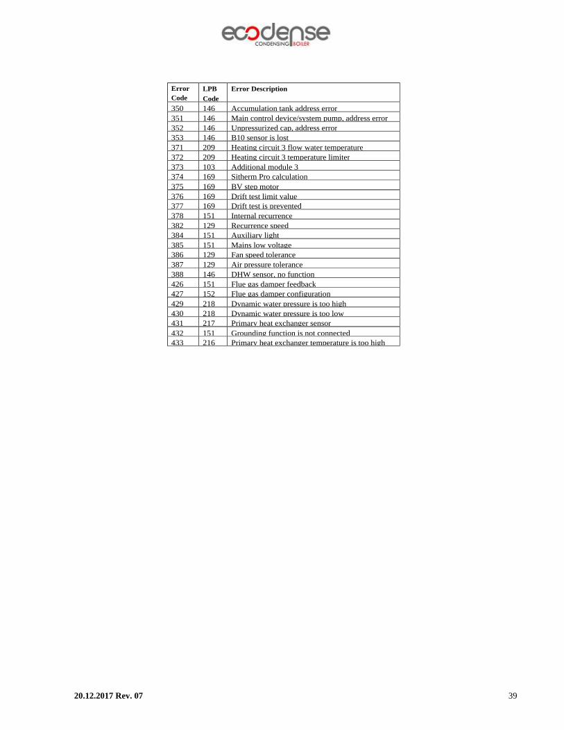
350 146 Accumulation tank address error 351 146 Main control device/system pump, address error 352 146 Unpressurized cap, address error 353 146 B10 sensor is lost 371 209 Heating circuit 3 flow water temperature 372 209 Heating circuit 3 temperature limiter 373 103 Additional module 3 374 169 Sitherm Pro calculation 375 169 BV step motor 376 169 Drift test limit value 377 169 Drift test is prevented 378 151 Internal recurrence 382 129 Recurrence speed 384 151 Auxiliary light 385 151 Mains low voltage 386 129 Fan speed tolerance 387 129 Air pressure tolerance 388 146 DHW sensor, no function 426 151 Flue gas damper feedback 427 152 Flue gas damper configuration 429 218 Dynamic water pressure is too high 430 218 Dynamic water pressure is too low 431 217 Primary heat exchanger sensor 432 151 Grounding function is not connected 433 216 Primary heat exchanger temperature is too high

20.12.2017 Rev. 07 40
SOLUTION RECOMMENDATIONS FOR SOME OF THE PROBLEMS
Problem Cause Explanation-Recommendation
Gas smell Gas line/Gas connections
Control of leak proofing of connections is required. Be sure that measurement points are closed.
Unburned gas smell Flue tightness Be sure that flue connections are leak proof and measurement points are closed. Check the combustion parameters.
Incomplete combustion
Gas supply pressure Check the gas pressure complies with stated values.
Fan problem Check the working of fan. State of premix combustion head and heat exchanger
Check the state of combustion head and heat exchanger and ensure that both are clean.
Combustion air connection
Check that there is nothing that blocks air suction and if the impulse connection is correct.
Shaky activation of burner
Gas pressure/Combustion parameters
Check the gas pressure and combustion parameters.
No combustion after ignition Electrode/Ionization Check the position/state of the electrode/ionization
rod.
Boiler does not work. Electric connection Check the fuse and electrical connections.
Sensor connections Ensure that connections of sensors are correct and complete.
Boiler can’t reach the desired temperature.
Gas pressure Ensure that gas pressure complies with stated values and there is constant gas flow at sufficient pressure.
Heat exchanger Control the state of combustion chamber.
Boiler control Control that boiler is at correct operation mod and temperature settings.
Safety valve activates often. Safety valve
Ensure that safety valve settings are correct and works properly.
Expansion tank Check if it works properly.
Pump does not work. Pump malfunction Check the pump electric connections and parameters. Change the pump if there is proble in pump operation.
20.12.2017 Rev. 07 41
AFTER SALES SERVICES Dear Customer, We believe that providing a good service is as important as providing a good product. Therefore, we continue offering wide range of comprehensive services to our conscious customers.
Our contact details for your requests and complaints: Esentepe Mah.Milangaz Cad. No:75 K:3
Kartal Monumento Plaza KARTAL/İSTANBUL/TÜRKİYE
Tel: +90 216 442 93 00 Fax: +90 216 370 45 03
Factory Contact Details Türkgücü OSB
Bülent Ecevit Bulvarı No:11 ÇORLU/TEKİRDAĞ/TÜRKİYE
Tel: +90 282 685 44 80-81 Fax: +90 282 685 42 09
You can also reach us through www.ecodense.com website and [email protected] e-mail address.
Please observe the following recommendations.
• Use the product in accordance with the principles of this manual. • For any service demands regarding the product, please contact our Service Center from the
above-mentioned phone numbers. • Upon your purchase, register your warranty certificate during installation.

20.12.2017 Rev. 07 42
NOTES
Please record and forward your measurements and observations to us. www.ecodense.com


