
COMPARTMENTALIZATION EFFECT IN GEOLOGIC CO2 SEQUESTRATION.
A CASE STUDY IN AN OFF-SHORE RESERVOIR IN ITALY
N. Castelletto, M. Ferronato, G. Gambolati, C. Janna, P. Teatini
Department of Civil, Environmental and Architectural Engineeringemail: [email protected] , http://www.dmsa.unipd.it/~teatini
OUTLINE
► INTRODUCTION
► SITE CHARACTERIZATION
► MATHEMATICAL MODELLING Modelling approach Geomechanics of the medium Geomechanics of the discontinuities
► RESULTS Failure of the injected formation Failure of the caproch Fault activation and induced micro-seismicity Surface displacement
► CONCLUSION
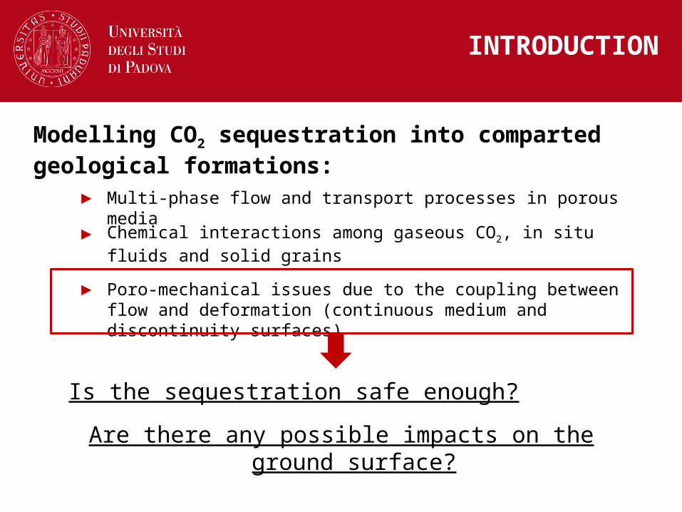
INTRODUCTION
Modelling CO2 sequestration into comparted geological formations:
► Multi-phase flow and transport processes in porous media
► Chemical interactions among gaseous CO2, in situ fluids and solid grains
► Poro-mechanical issues due to the coupling between flow and deformation (continuous medium and discontinuity surfaces)
Is the sequestration safe enough?
Are there any possible impacts on the ground surface?
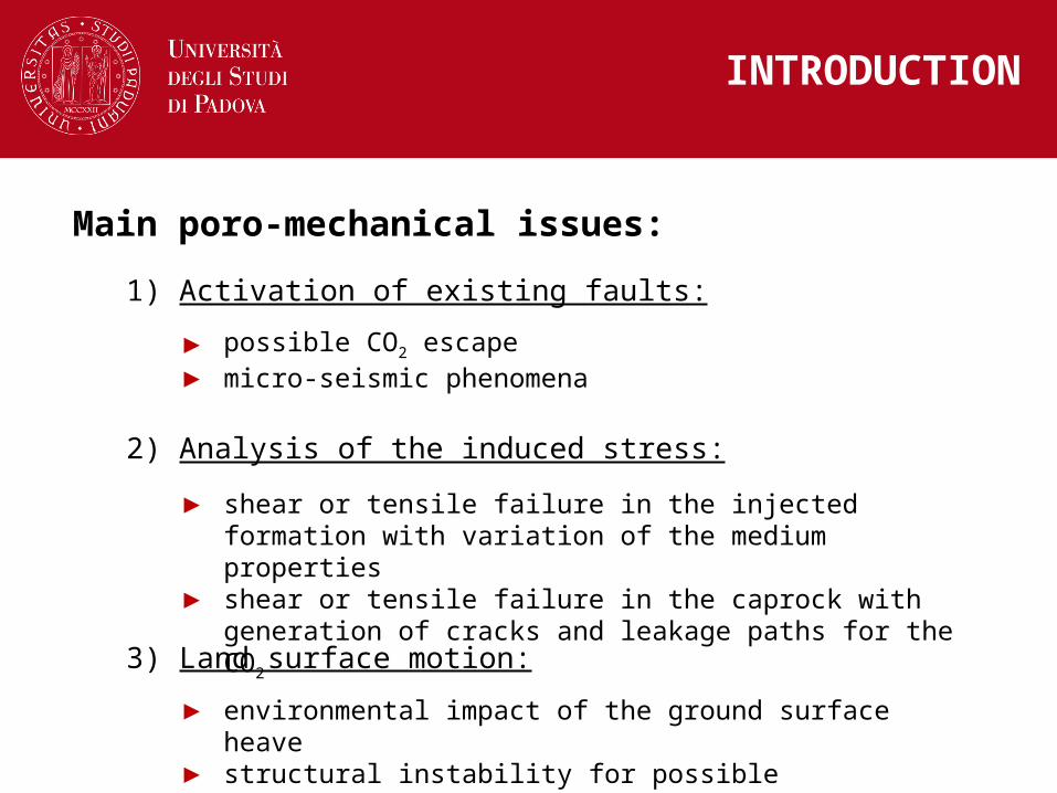
Main poro-mechanical issues:
1) Activation of existing faults:
► possible CO2 escape► micro-seismic phenomena
2) Analysis of the induced stress:
► shear or tensile failure in the injected formation with variation of the medium properties
► shear or tensile failure in the caprock with generation of cracks and leakage paths for the CO2
3) Land surface motion:
► environmental impact of the ground surface heave► structural instability for possible differential displacements
INTRODUCTION

Within the European Energy Programme for Recovery (EEPR), ENEL (the largest Italian energy provider) is planning a pilot project to inject underground 1Mt/yr (10% of the plant production) for 10 years
Several partners:
ENI : geological data end injection knowledgment
OGS-National Geophysical Institute : specific geophysical interpretation
IFP-Institute Francais du Petrole : flow model (COORES)
Univ. Padova : geomechanical model (GEPS3D)
SAIPEM (Eni) : geochemical issues
SITE LOCATION &PROJECT DESCRIPTION
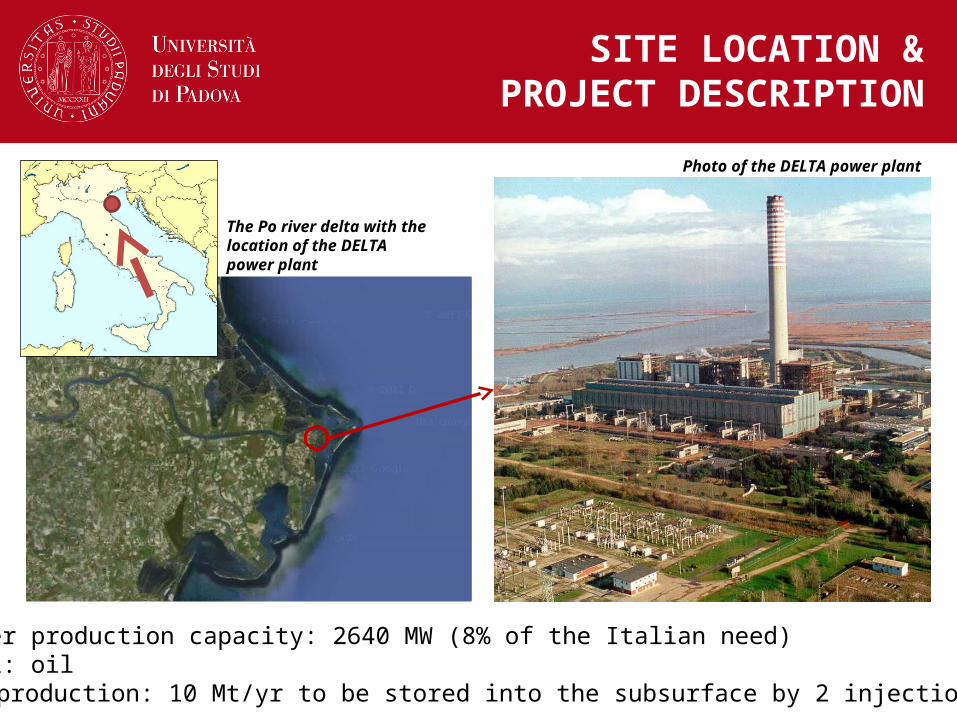
Photo of the DELTA power plant
The Po river delta with the location of the DELTA power plant
► power production capacity: 2640 MW (8% of the Italian need)► fuel: oil► CO2 production: 10 Mt/yr to be stored into the subsurface by 2 injection wells
SITE LOCATION &PROJECT DESCRIPTION
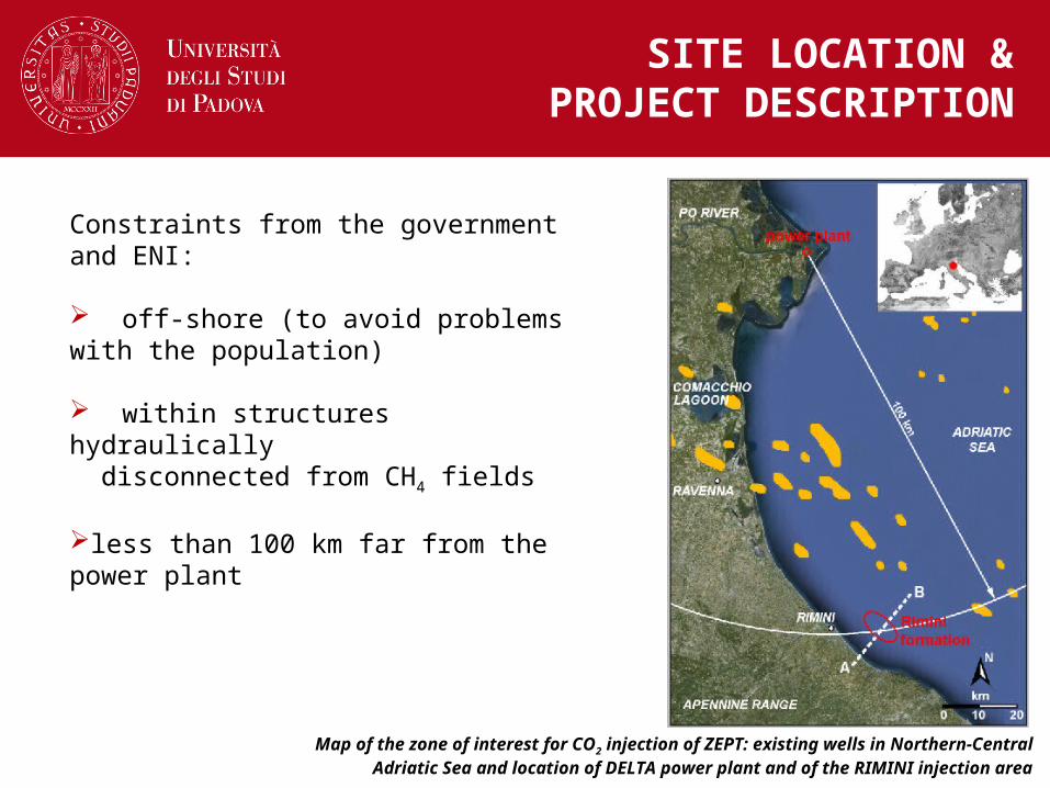
Map of the zone of interest for CO2 injection of ZEPT: existing wells in Northern-Central Adriatic Sea and location of DELTA power plant and of the RIMINI injection area
Constraints from the government and ENI:
off-shore (to avoid problems with the population)
within structures hydraulically disconnected from CH4 fields
less than 100 km far from the power plant
SITE LOCATION &PROJECT DESCRIPTION
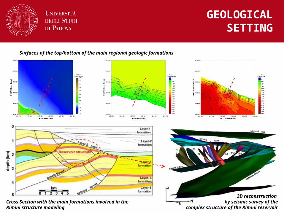
Cross Section with the main formations involved in the Rimini structure modeling
3D reconstruction by seismic survey of the
complex structure of the Rimini reservoir
Surfaces of the top/bottom of the main regional geologic formations
GEOLOGICALSETTING
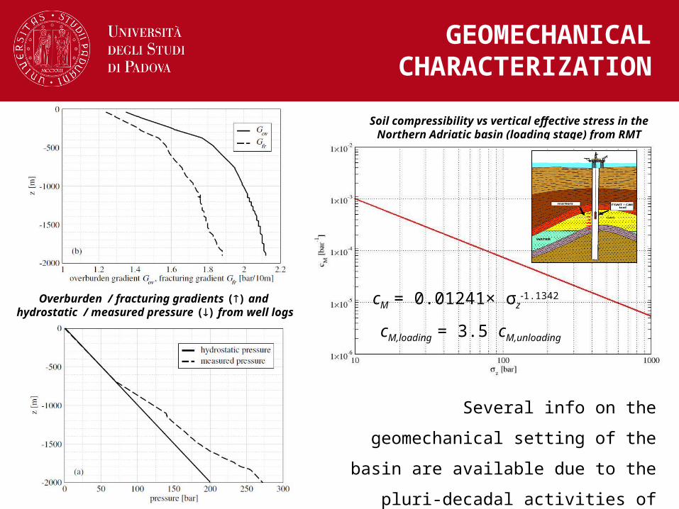
Several info on the geomechanical setting
of the basin are available due to the pluri-
decadal activities of hydrocarbon
exploration and production
Soil compressibility vs vertical effective stress in the Northern Adriatic basin (loading stage) from RMT
cM = 0.01241× σz-1.1342
cM,loading = 3.5 cM,unloading
GEOMECHANICALCHARACTERIZATION
Overburden / fracturing gradients () and hydrostatic / measured pressure () from well logs
MODELLING APPROACH
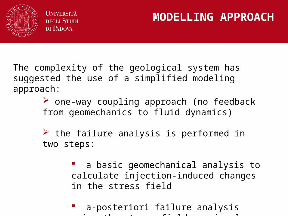
one-way coupling approach (no feedback from geomechanics to fluid dynamics)
the failure analysis is performed in two steps:
a basic geomechanical analysis to calculate injection-induced changes in the stress field
a-posteriori failure analysis using the stress field previously calculated
The complexity of the geological system has suggested the use of a simplified modeling approach:

MATHEMATICAL MODELLINGGeomechanics of the medium
Mechanical model of the continuum:
► Terzaghi-Bishop relationship:
► Cauchy equations with a constitutive model:
with
cwwggww pSppSpS 1ˆ
cww
TT pSp 1 D
► Constitutive mechanical model:
Hypo-plastic law with hysteresis:
IcM
trace211
1
path stress ,MM cc
solvedby FE
s
ne K
KD
0
0
Mohr-Coulomb failure criterion as yield surface
0 0
0 0tan
ns
nns
cF
cF
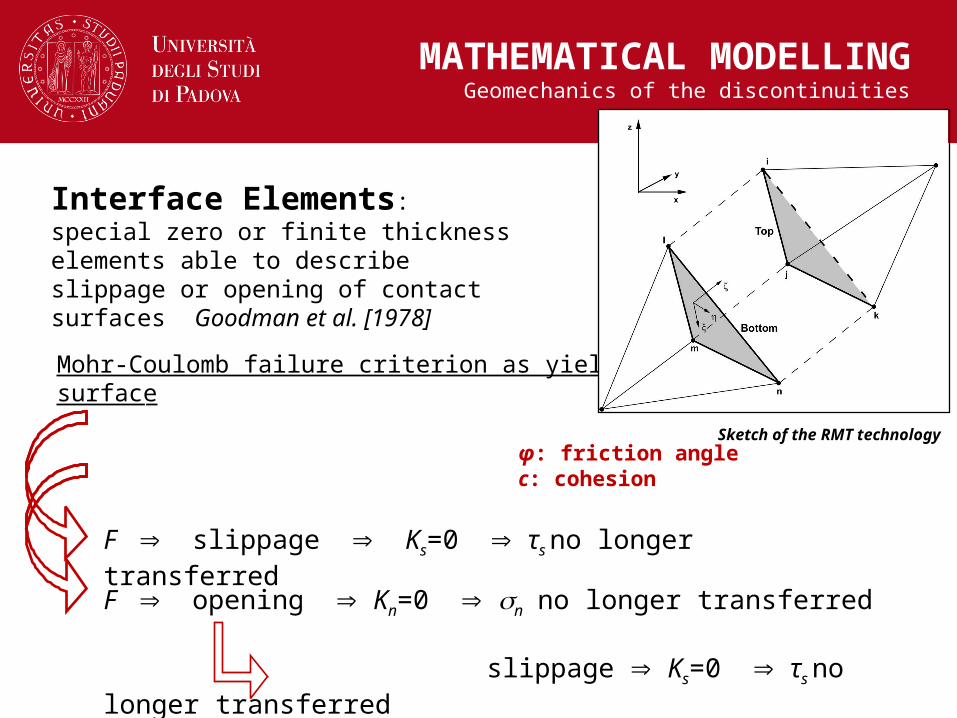
φ: friction angle c: cohesion
F slippage Ks=0 τs no longer transferred
F opening Kn=0 n no longer transferred
slippage Ks=0 τs no longer transferred
Interface Elements: special zero or finite thickness elements able to describe slippage or opening of contact surfaces Goodman et al. [1978]
MATHEMATICAL MODELLINGGeomechanics of the discontinuities
Sketch of the RMT technology
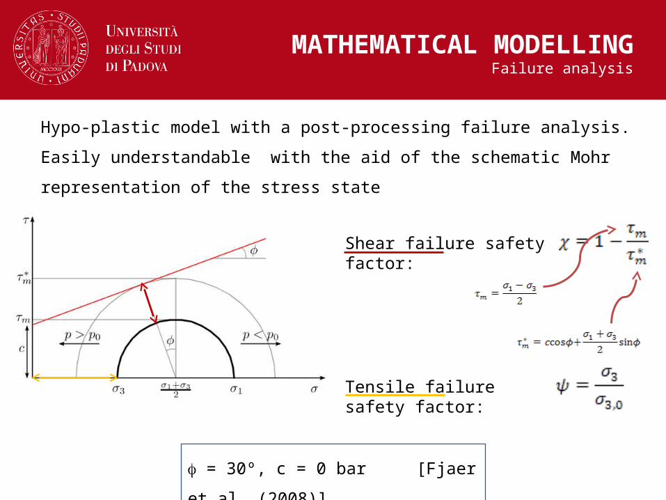
Hypo-plastic model with a post-processing failure analysis. Easily understandable
with the aid of the schematic Mohr representation of the stress state
Shear failure safety factor:
Tensile failure safety factor:
= 30º, c = 0 bar [Fjaer et al. (2008)]
MATHEMATICAL MODELLINGFailure analysis
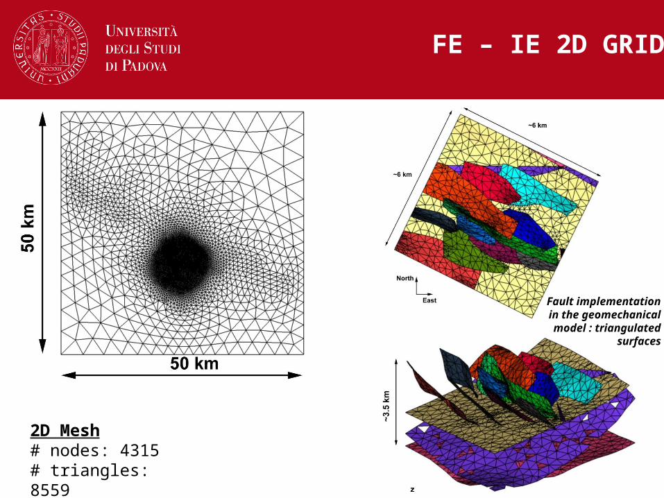
FE – IE 2D GRID
Fault implementation in the geomechanical
model : triangulated surfaces
2D Mesh# nodes: 4315# triangles: 8559
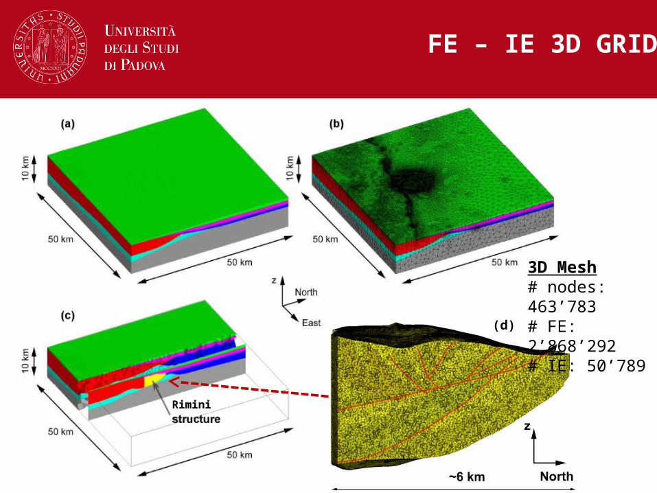
Rimini
FE – IE 3D GRID
3D Mesh# nodes: 463’783# FE: 2’868’292# IE: 50’789(d)
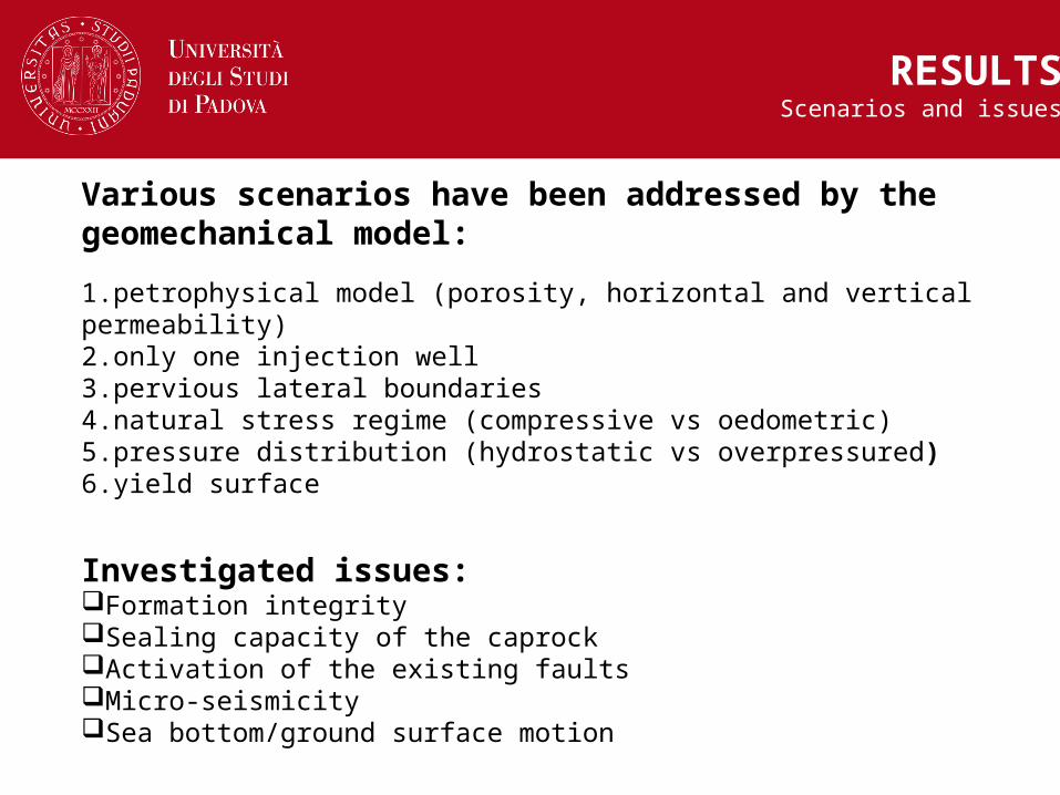
Various scenarios have been addressed by the geomechanical model:
1.petrophysical model (porosity, horizontal and vertical permeability)2.only one injection well3.pervious lateral boundaries4.natural stress regime (compressive vs oedometric)5.pressure distribution (hydrostatic vs overpressured)6.yield surface
Investigated issues:Formation integritySealing capacity of the caprockActivation of the existing faultsMicro-seismicitySea bottom/ground surface motion
RESULTSScenarios and issues
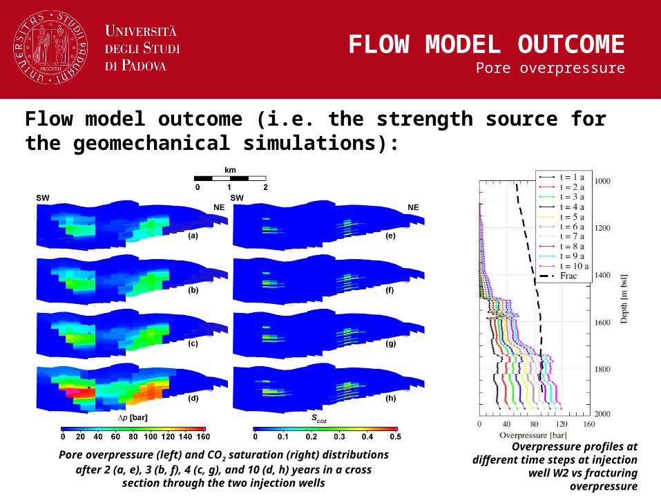
Flow model outcome (i.e. the strength source for the geomechanical simulations):
FLOW MODEL OUTCOMEPore overpressure
Overpressure profiles at different time steps at injection
well W2 vs fracturing overpressure
Pore overpressure (left) and CO2 saturation (right) distributions after 2 (a, e), 3 (b, f), 4 (c, g), and 10 (d, h) years in a cross
section through the two injection wells
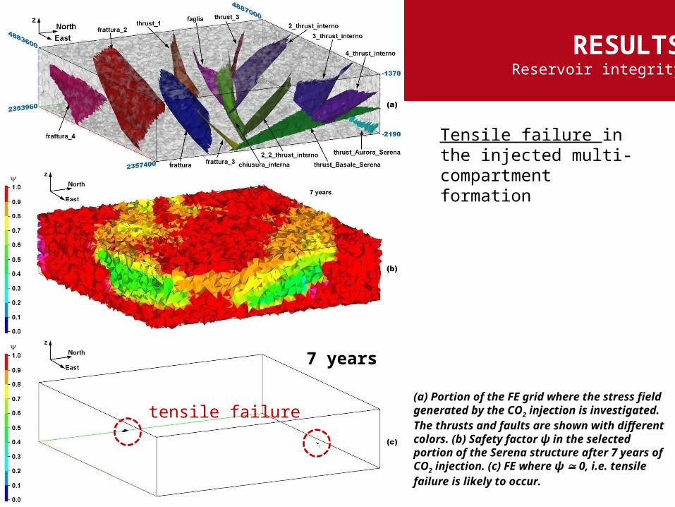
(a) Portion of the FE grid where the stress field generated by the CO2 injection is investigated. The thrusts and faults are shown with different colors. (b) Safety factor ψ in the selected portion of the Serena structure after 7 years of CO2 injection. (c) FE where ψ 0, i.e. tensile failure is likely to occur.
tensile failure
RESULTSReservoir integrity
Tensile failure in the injected multi-compartment formation
7 years

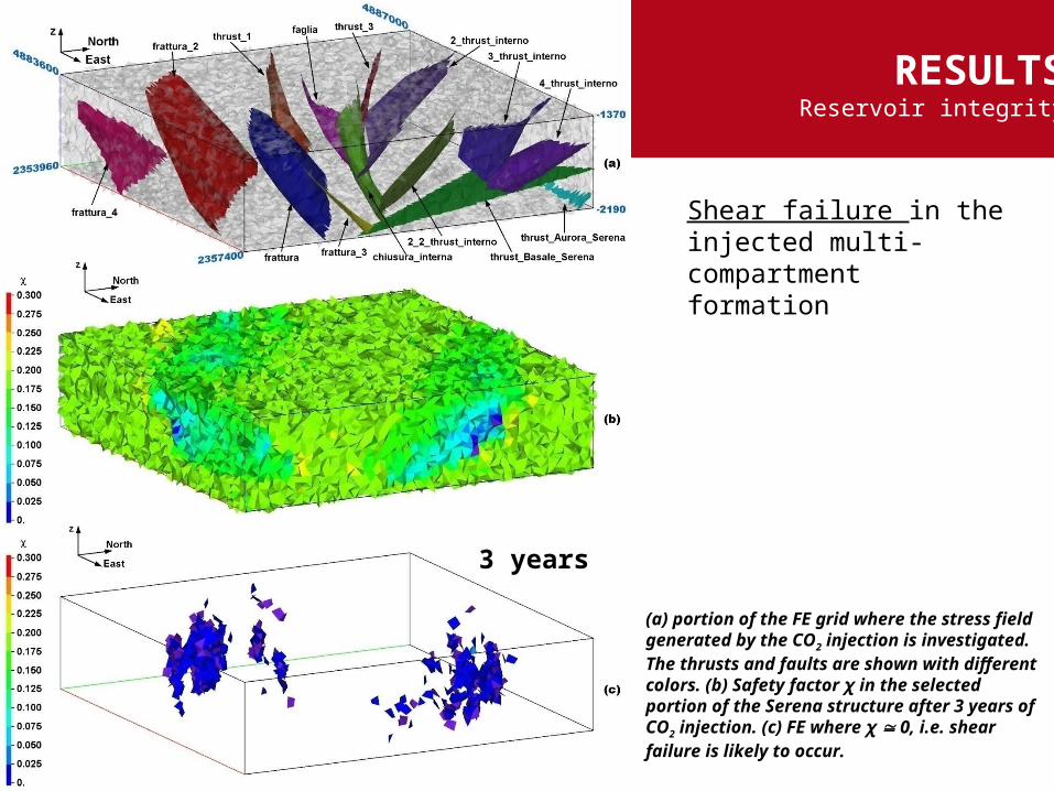
shear failure
RESULTSReservoir integrity
(a) portion of the FE grid where the stress field generated by the CO2 injection is investigated. The thrusts and faults are shown with different colors. (b) Safety factor χ in the selected portion of the Serena structure after 1 year of CO2 injection. (c) FE where χ 0, i.e. shear failure is likely to occur.
1 year
Shear failure in the injected multi-compartment formation

RESULTSReservoir integrity
(a) portion of the FE grid where the stress field generated by the CO2 injection is investigated. The thrusts and faults are shown with different colors. (b) Safety factor χ in the selected portion of the Serena structure after 2 years of CO2 injection. (c) FE where χ 0, i.e. shear failure is likely to occur.
2 years
Shear failure in the injected multi-compartment formation
RESULTSReservoir integrity
(a) portion of the FE grid where the stress field generated by the CO2 injection is investigated. The thrusts and faults are shown with different colors. (b) Safety factor χ in the selected portion of the Serena structure after 3 years of CO2 injection. (c) FE where χ 0, i.e. shear failure is likely to occur.
3 years
Shear failure in the injected multi-compartment formation
RESULTSReservoir integrity
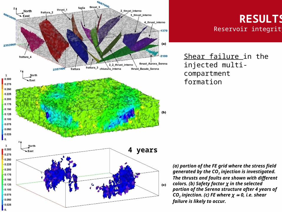
(a) portion of the FE grid where the stress field generated by the CO2 injection is investigated. The thrusts and faults are shown with different colors. (b) Safety factor χ in the selected portion of the Serena structure after 4 years of CO2 injection. (c) FE where χ 0, i.e. shear failure is likely to occur.
4 years
Shear failure in the injected multi-compartment formation
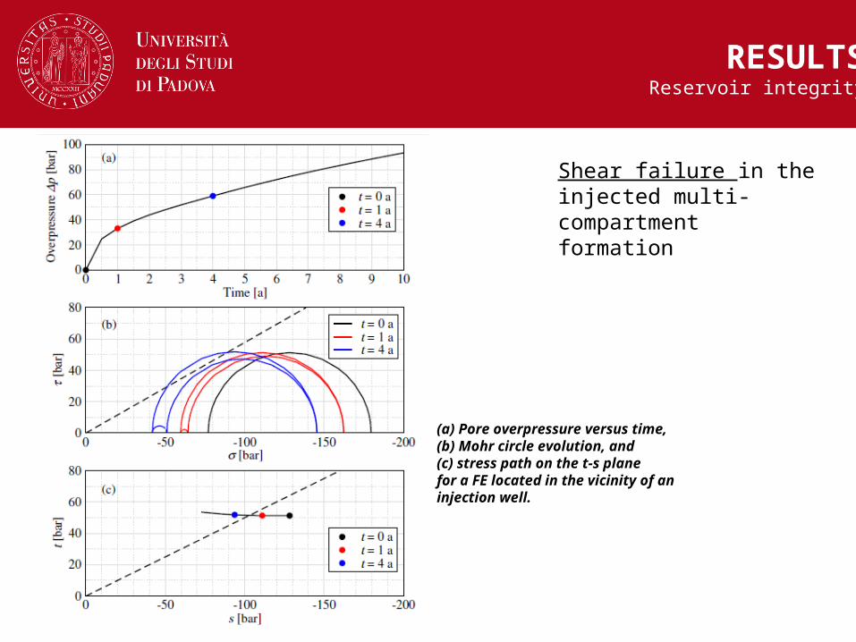
RESULTSReservoir integrity
(a) Pore overpressure versus time, (b) Mohr circle evolution, and(c) stress path on the t-s plane for a FE located in the vicinity of an injection well.
Shear failure in the injected multi-compartment formation

Horizontal view of the safety factors χ (left) and ψ (right) at the bottom of the caprock sealing the injected formation after 7 years of CO2 injection
RESULTSCaprock integrity
Evaluation of possible failure conditions in the caprock bounding the reservoir

(above) Modulus of the stress τs tangential to the fault and thrust surfaces after 7 years
of CO2 injection. (below) Active (red) and inactive (blue) IE: red elements slip due to the stress change induced by the injection
RESULTSFault activation / Induced seismicity
The methodology advanced by Mazzoldi et al. (IJGGC, 2012) is followed:
the seismic moment (M0) of an earthquake for a rupture patch on a fault is defined by:
M0 is then used to evaluate the magnitude (M) by the equation:
G: shear modulus of the host rocks: average slipA : area of the activated fault
G = 1.5×10⁹ Nm2
s: ~ 1-2 mmA = 104 m2
M ≈ 1
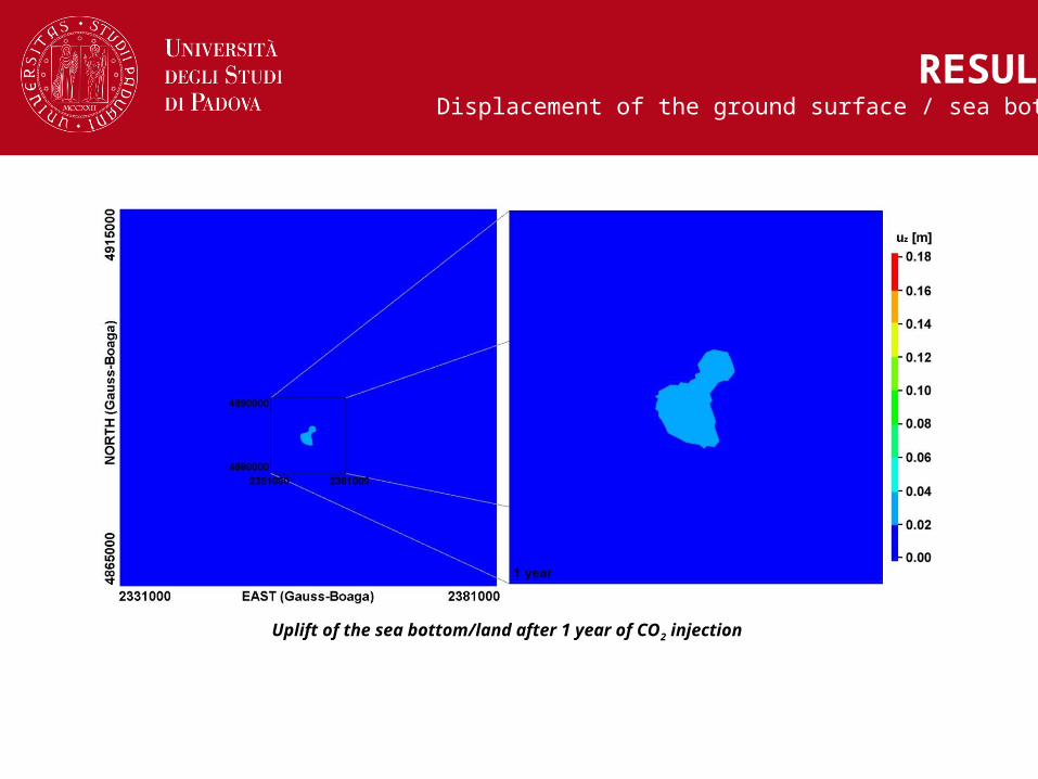
Uplift of the sea bottom/land after 1 year of CO2 injection
RESULTSDisplacement of the ground surface / sea bottom
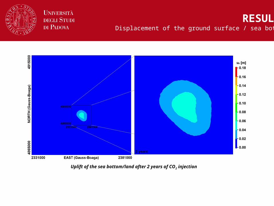
Uplift of the sea bottom/land after 2 years of CO2 injection
RESULTSDisplacement of the ground surface / sea bottom
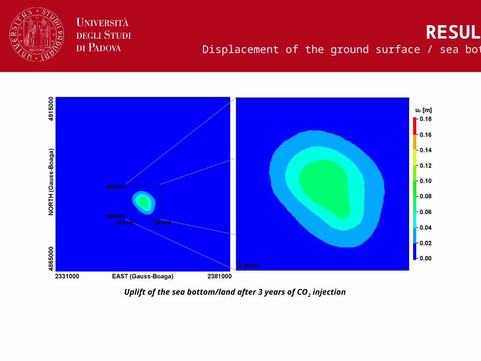
Uplift of the sea bottom/land after 3 years of CO2 injection
RESULTSDisplacement of the ground surface / sea bottom
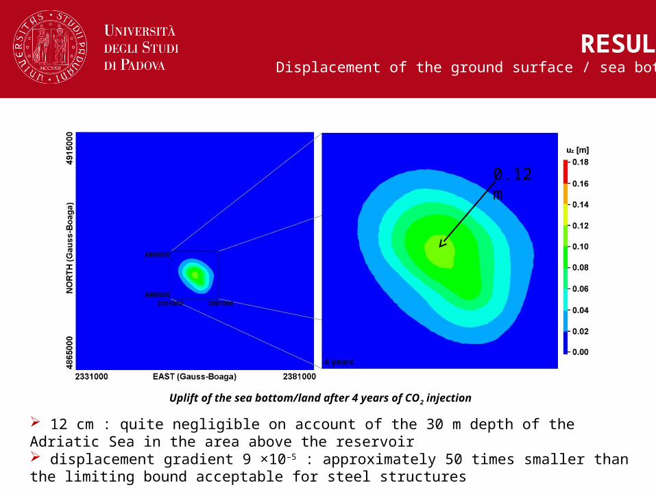
Uplift of the sea bottom/land after 4 years of CO2 injection
RESULTSDisplacement of the ground surface / sea bottom
0.12 m
12 cm : quite negligible on account of the 30 m depth of the Adriatic Sea in the area above the reservoir displacement gradient 9 ×10⁻⁵ : approximately 50 times smaller than the limiting bound acceptable for steel structures
► the FE-IE mesh accurately reproduce the regional geometry of the geological formations, the horizons bounding the structure and the orientation and extent of the discontinuity surfaces (faults and thrusts)
► the geomechanical issues can play a most important role in relation to a safe geological disposal of carbon dioxide in multi-compartment reservoirs
► the geomechanical simulations indicate that shear failure in large portion of the reservoir is likely to occur well in advance to tensile failure (independently of the various scenarios investigated in the study)
Conclusions
a new larger reservoir is under investigation

DICEADepartment of Civil,
Emvironmental and Architectural Engineering
Thank you for your attention


