Catalytic Pellet Reactor Under Uncertainty Design
Catalytic Pellet Reactor Under Uncertainty Catalytic Pellet Reactor Under Uncertainty DesignDesign
Final Presentation at the REU meeting Chicago, IL, Tuesday, Aug. 4th, 2005.
Presenter: Celia Xue
Advisors: Pf. LinningerDr. Libin Zhang
Laboratory for Product and Process Design, Department of Chemical Engineering, University of Illinois,
Chicago, IL 60607, U.S.A.
LPPDLPPDCelia
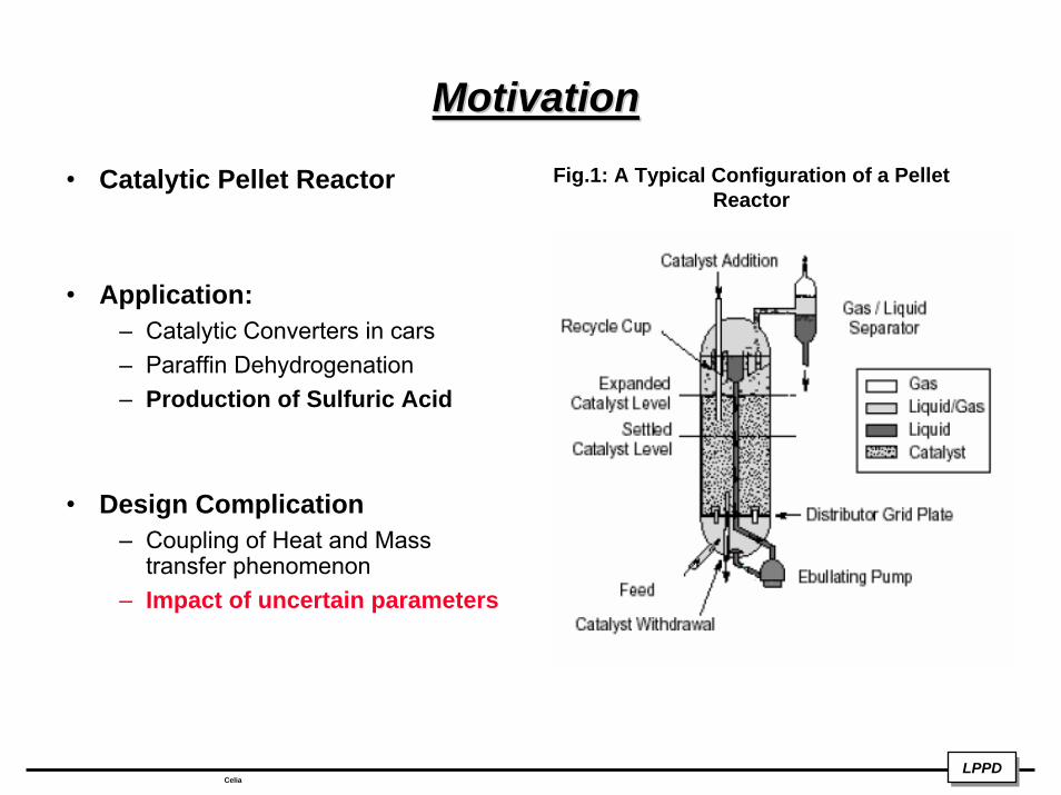
MotivationMotivationFig.1: A Typical Configuration of a Pellet
Reactor• Catalytic Pellet Reactor
• Application:– Catalytic Converters in cars– Paraffin Dehydrogenation– Production of Sulfuric Acid
• Design Complication– Coupling of Heat and Mass
transfer phenomenon– Impact of uncertain parameters
LPPDLPPDCelia
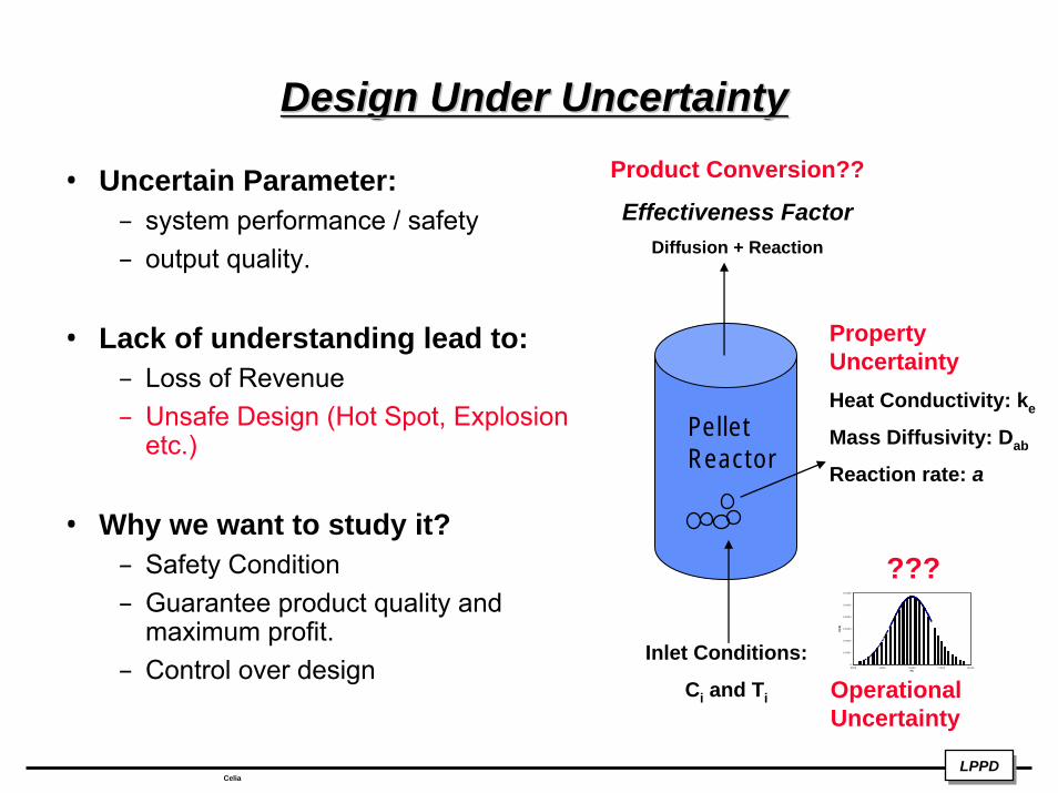
Design Under UncertaintyDesign Under UncertaintyProduct Conversion??
Effectiveness FactorDiffusion + Reaction
• Uncertain Parameter: – system performance / safety – output quality.
• Lack of understanding lead to:– Loss of Revenue– Unsafe Design (Hot Spot, Explosion
etc.)
• Why we want to study it?– Safety Condition – Guarantee product quality and
maximum profit.– Control over design
Pellet Reactor
Inlet Conditions:
Ci and Ti
0
0.0001
0.0002
0.0003
0.0004
0.0005
0.0006
80 00 90 00 10000 1 1000 12000Fb
P(Fb
)
???
Operational Uncertainty
Property UncertaintyHeat Conductivity: ke
Mass Diffusivity: Dab
Reaction rate: a
LPPDLPPDCelia
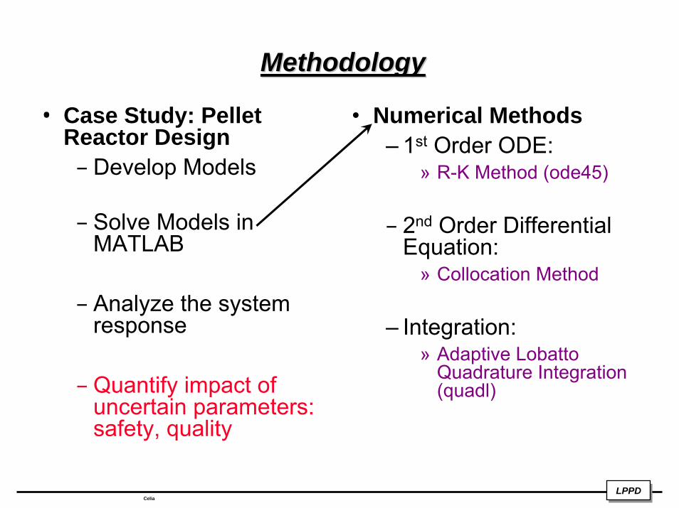
MethodologyMethodology
• Case Study: Pellet Reactor Design– Develop Models
– Solve Models in MATLAB
– Analyze the system response
– Quantify impact of uncertain parameters: safety, quality
• Numerical Methods– 1st Order ODE:
» R-K Method (ode45)
– 2nd Order Differential Equation:
» Collocation Method
– Integration: » Adaptive Lobatto
Quadrature Integration (quadl)
LPPDLPPDCelia
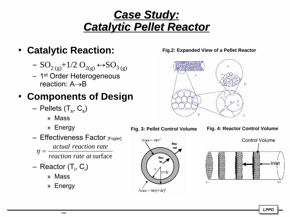
Case Study: Case Study: Catalytic Pellet ReactorCatalytic Pellet Reactor
• Catalytic Reaction:– SO2 (g)+1/2 O2(g) ↔SO3 (g)– 1st Order Heterogeneous
reaction: A→B
• Components of Design– Pellets (Ts, Cs)
» Mass» Energy
– Effectiveness Factor [Fogler]
– Reactor (Ti, Ci)» Mass» Energy
surfaceatratereactionratereactionactual
=η
Fig. 3: Pellet Control Volume Fig. 4: Reactor Control Volume
Fig.2: Expanded View of a Pellet Reactor
Control Volume
Inlet
LPPDLPPDCelia
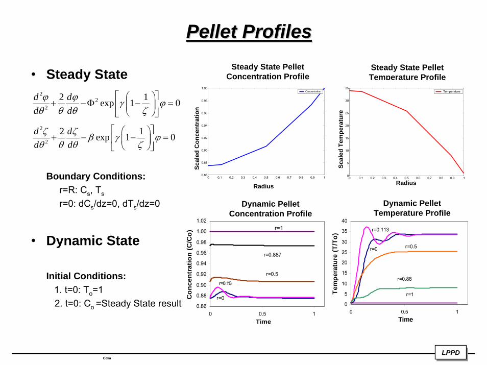
Pellet Profiles Pellet Profiles
• Steady State
Boundary Conditions:r=R: Cs, Ts
r=0: dCs/dz=0, dTs/dz=0
• Dynamic State
Initial Conditions:1. t=0: To=12. t=0: Co =Steady State result
Steady State Pellet Temperature Profile
Steady State Pellet Concentration Profile
22
2
2 1exp 1 0d dd dϕ ϕ γ ϕθ θ θ ζ
⎡ ⎤⎛ ⎞+ −Φ − =⎢ ⎥⎜ ⎟
⎝ ⎠⎣ ⎦2
2
2 1exp 1 0d dd dζ ζ β γ ϕθ θ θ ζ
⎡ ⎤⎛ ⎞+ − − =⎢ ⎥⎜ ⎟
⎝ ⎠⎣ ⎦
0 0.1 0.2 0.3 0.4 0.5 0.6 0.7 0.8 0.9 10.86
0.88
0.90
0.92
0.94
0.96
0.98
1.00
di
Concentration
0 0.1 0.2 0.3 0.4 0.5 0.6 0.7 0.8 0.9 10
5
10
15
20
25
30
35
p
Temperature
0.86
0.88
0.90
0.92
0.94
0.96
0.98
1.00
1.02
0 0.5 1Time
Con
cent
ratio
n (C
/Co)
r=1
r=0.887
r=0.5
r=0.113
r=00
5
10
15
20
25
30
35
40
0 0.5 1Time
Tem
pera
ture
(T/T
o)
r=0
r=0.113
r=0.5
r=0.88
r=1
Dynamic Pellet Concentration Profile
Dynamic Pellet Temperature Profile
Radius Radius
Scal
ed C
once
ntra
tion
Scal
ed T
empe
ratu
re
LPPDLPPDCelia
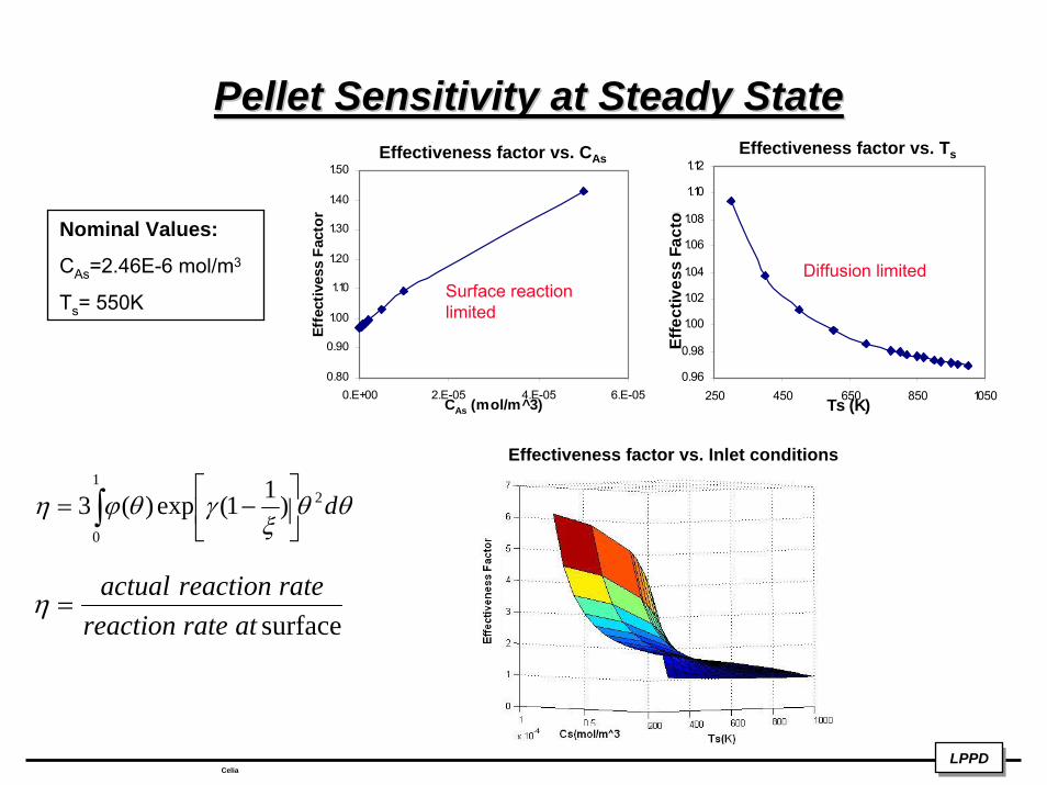
Pellet Sensitivity at Steady StatePellet Sensitivity at Steady State
0.80
0.90
1.00
1.10
1.20
1.30
1.40
1.50
0.E+00 2.E-05 4.E-05 6.E-05CAs (mol/m^3)
Effe
ctiv
ess
Fact
or
0.96
0.98
1.00
1.02
1.04
1.06
1.08
1.10
1.12
250 450 650 850 1050Ts (K)
Effe
ctiv
ess
Fact
or
surfaceatratereactionratereactionactual
=η
Effectiveness factor vs. TsEffectiveness factor vs. CAs
Diffusion limitedSurface reaction limited
Nominal Values:
CAs=2.46E-6 mol/m3
Ts= 550K
LPPDLPPDCelia
Effectiveness factor vs. Inlet conditions
θθξ
γθϕη d21
0
)11(exp)(3∫ ⎥⎦
⎤⎢⎣
⎡−=
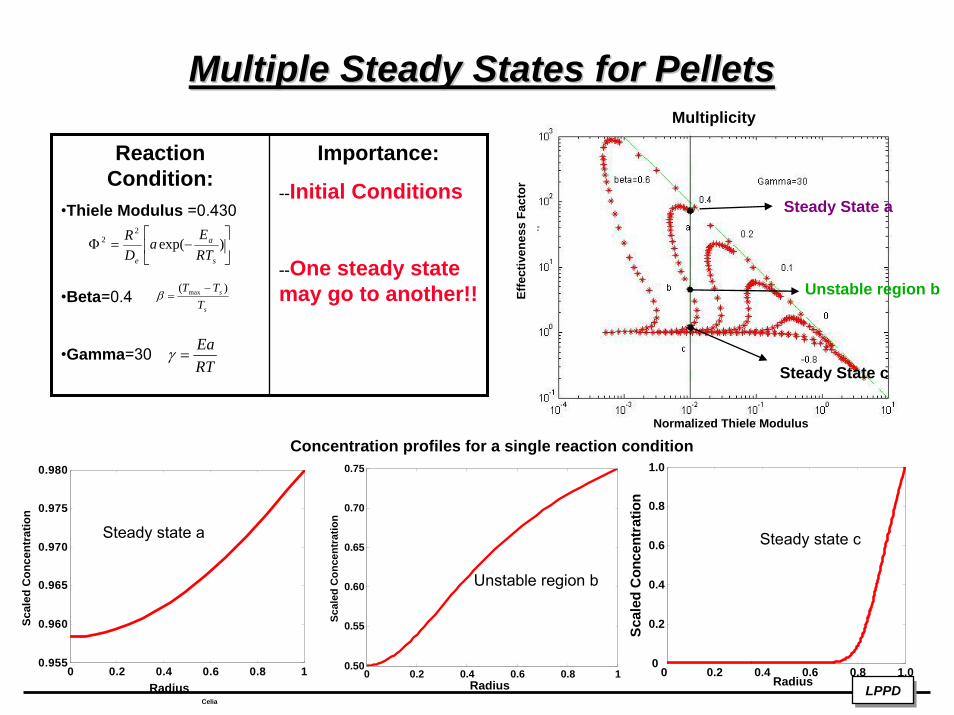
Multiple Steady States for PelletsMultiple Steady States for Pellets
LPPDLPPDCelia
0 0.2 0.4 0.6 0.8 10.50
0.55
0.60
0.65
0.70
0.75
Scal
ed C
once
ntra
tion
0 0.2 0.4 0.6 0.8 1.00
0.2
0.4
0.6
0.8
1.0
Scal
ed C
once
ntra
tion
0 0.2 0.4 0.6 0.8 10.955
0.960
0.965
0.970
0.975
0.980
Scal
ed C
once
ntra
tion
Reaction Condition:
•Thiele Modulus =0.430
•Beta=0.4
•Gamma=30
Importance:
--Initial Conditions
--One steady state may go to another!!
⎥⎦
⎤⎢⎣
⎡−=Φ )exp(
22
s
a
e RTE
aDR
s
s
TTT )( max −=β
RTEa
=γ
Steady state a
Unstable region b
Steady state c
Normalized Thiele Modulus
Radius Radius Radius
Concentration profiles for a single reaction condition
Multiplicity
Effe
ctiv
enes
s Fa
ctor
Steady State a
Unstable region b
Steady State c
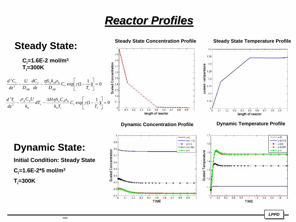
Reactor ProfilesReactor ProfilesSteady State Concentration Profile Steady State Temperature ProfileSteady State:
Ci=1.6E-2 mol/m3
Ti=300K
0)11(exp2
2
=⎥⎦
⎤⎢⎣
⎡−−−
rr
AB
boar
AB
r
TC
DkS
dzdC
DU
dzCd
γρη
0)11(exp2
2
=⎥⎦
⎤⎢⎣
⎡−
∆−−
rr
ib
biar
b
pgr
TC
TkCSH
dTk
UCdz
Tdγ
ρηρ
Dynamic Temperature ProfileDynamic Concentration Profile
Dynamic State:Initial Condition: Steady State
Ci=1.6E-2*5 mol/m3
Ti=300K
LPPDLPPDCelia
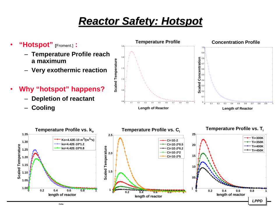
Reactor Safety: HotspotReactor Safety: Hotspot
LPPDLPPDCelia
0 0.2 0.4 0.6 0.8 11
1.05
1.10
1.15
1.20
1.25
length of reactor
Scal
ed T
empe
ratu
re
Ti=300KTi=350KTi=400KTi=450K
0 0.2 0.4 0.6 0.8 11.00
1.05
1.10
1.15
1.20
1.25
1.30
1.35
length of reactor
Scal
ed T
empe
ratu
re
Ko=4.42E-10 m3/(m2*s)ko=4.42E-10*1.2ko=4.42E-10*0.8
0 0.2 0.4 0.6 0.8 11
1.5
2.0
2.5
length of reactor
Scal
ed T
empe
ratu
re
Ci=1E-2Ci=1E-2*0.5Ci=1E-2*0.2Ci=1E-2*2Ci=1E-2*5
• “Hotspot” [Froment.] :– Temperature Profile reach
a maximum– Very exothermic reaction
• Why “hotspot” happens?– Depletion of reactant– Cooling
0 0.1 0.2 0.3 0.4 0.5 0.6 0.7 0.8 0.9 11.00
1.05
1.10
1.15
1.20
1.25
0 0.1 0.2 0.3 0.4 0.5 0.6 0.7 0.8 0.9 10
0.1
0.2
0.3
0.4
0.5
0.6
0.7
0.8
0.9
1.0
Temperature Profile Concentration Profile
Temperature Profile vs. CiTemperature Profile vs. Ti
Scal
ed T
empe
ratu
re
Scal
ed C
once
ntra
tion
Temperature Profile vs. ko
Length of Reactor Length of Reactor
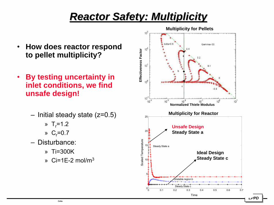
Reactor Safety: MultiplicityReactor Safety: Multiplicity
LPPDLPPDCelia
0 0.1 0.2 0.3 0.4 0.5 0.6 0.70
5
10
15
20
25
Time
Sca
led
Tem
pera
ture
Steady State a
Unstable region b
Steady State c
Ideal Design Steady State c
Unsafe Design Steady State a
Normalized Thiele Modulus
Multiplicity for Pellets
Multiplicity for Reactor
• How does reactor respond to pellet multiplicity?
• By testing uncertainty in inlet conditions, we find unsafe design!
– Initial steady state (z=0.5)» Tr=1.2» Cr=0.7
– Disturbance: » Ti=300K» Ci=1E-2 mol/m3
Effe
ctiv
enes
s Fa
ctor
ConclusionConclusion
– Pellet steady/dynamic state profiles
– Multiplicity in pellets
– Reactor steady/dynamic state profiles
– Reactor “hotspot”
– Uncertainty analysis helps to prevent unsafe design!
LPPDLPPDCelia
ReferencesReferences
• 1. Malcom, A,; Linninger, A.A; “Integrating Design ad Control: Dynamic Analysis of Flexible Operation.”http://viena.che.edu/research/designcontrol/DesigControl.pdf. [June 8, 2005.]
• 2. Fogler H. Scott, Elements of Chemical Reaction Engineering, 3rd Ed., Prentice Hall PTR, 1999.
• 3. Froment Gilbert F. and Bischoff Kenneth B. Chemical Reactor Analysis and Design, 2nd Ed. John Wiley & Sons, Inc., Canada, 1979.
• 4. Catalytic Pellet Reactor. http://jbrwww.che.wisc.edu/~jbraw/chemreacfun/ ch7/slides-masswrxn.pdf. [July 11th, 2005]
• 5. Perkins Victor and Gomez Javier Cruz. Assessment of Electricity Generation to 2011 Using Low Sulfur Fuel Oil in Mexico. http://www.iaee.org/documents/AssessmentofElectricityGenerationto2011UsingLowSulfurFuelOilinMexicoVictorBazC3A1nPerkinsJavierCruzGC3B3mez.pdf. [July 11th, 2005]
LPPDLPPDCelia
AcknowledgementAcknowledgement
• NSF DMI 0328134 REU Supplement (Linninger) PI
LPPDLPPDCelia


