
Australian Technical Specification for Fabricated Water Control Infrastructure
DC221-09-0815 Page 1 of 35
Australian Technical Specification for Fabricated Water Control Infrastructure
Revision 9
28th August 2015

Australian Technical Specification for Fabricated Water Control Infrastructure
DC221-09-0815 Page 2 of 35
Table of Contents
Preface .................................................................................................................................................... 8�
1� Introduction .................................................................................................................................... 9�
1.1� Preamble ................................................................................................................................. 9�
1.2� Scope ....................................................................................................................................... 9�
2� Interpretation ................................................................................................................................. 9�
2.1� Definitions ............................................................................................................................... 9�
Aperture .......................................................................................................................................... 9�
Crevice ............................................................................................................................................. 9�
Door ................................................................................................................................................ 9�
Frame .............................................................................................................................................. 9�
Headstock ....................................................................................................................................... 9�
Pedestal ........................................................................................................................................... 9�
WCD .............................................................................................................................................. 10�
Head .............................................................................................................................................. 10�
Sill/Invert ....................................................................................................................................... 10�
Inspection and Test Plan (ITP) ....................................................................................................... 10�
Leakage ......................................................................................................................................... 10�
Manufacturer ................................................................................................................................ 10�
Maximum Static Head ................................................................................................................... 10�
Notation ........................................................................................................................................ 10�
Owner/Purchaser .......................................................................................................................... 10�
Operator Platform Level ............................................................................................................... 10�
Off‐Seating .................................................................................................................................... 10�
On‐Seating ..................................................................................................................................... 10�
Quality System .............................................................................................................................. 11�
Seals .............................................................................................................................................. 11�

Australian Technical Specification for Fabricated Water Control Infrastructure
DC221-09-0815 Page 3 of 35
Seat ............................................................................................................................................... 11�
Site ................................................................................................................................................ 11�
Stopboard ..................................................................................................................................... 11�
Supplier ......................................................................................................................................... 12�
Testing ........................................................................................................................................... 12�
2.2� Units ...................................................................................................................................... 13�
2.3� Conflict in Documentation .................................................................................................... 13�
3� Systems ......................................................................................................................................... 13�
3.1� Supplier Accreditation ........................................................................................................... 13�
3.2� ITP ......................................................................................................................................... 13�
3.3� Quality Systems ..................................................................................................................... 13�
3.4� Occupational Health & Safety (OH&S) and Environmental Compliance .............................. 14�
3.5� Supplier Capability Profile ..................................................................................................... 14�
3.6� Approvals and Required Inspections .................................................................................... 14�
4� Design Requirements .................................................................................................................... 14�
4.1� Design Scope ......................................................................................................................... 14�
4.2� General Design Considerations ............................................................................................. 14�
4.3� Project Specific Requirements .............................................................................................. 14�
4.3.1� Design Life ..................................................................................................................... 14�
4.3.2� Design Responsibility .................................................................................................... 14�
4.3.3� Welded Joints ................................................................................................................ 15�
4.3.4� Environmental Considerations ...................................................................................... 15�
4.4� General .................................................................................................................................. 15�
4.4.1� Actuation ....................................................................................................................... 15�
4.4.2� Impact Loads ................................................................................................................. 15�
4.4.3� Leakage Rate ................................................................................................................. 15�
4.4.4� Maximum Head Pressure and Seating .......................................................................... 16�

Australian Technical Specification for Fabricated Water Control Infrastructure
DC221-09-0815 Page 4 of 35
4.4.5� Design Head Pressure ................................................................................................... 16�
4.4.6� Tail Water ...................................................................................................................... 16�
4.5� Civil Design ............................................................................................................................ 16�
4.6� Civil Aperture Dimensions ..................................................................................................... 16�
4.7� Frame .................................................................................................................................... 16�
4.7.1� Stainless Steel ............................................................................................................... 16�
4.7.2� Aluminium ..................................................................................................................... 16�
4.7.3� Frame Seal ..................................................................................................................... 17�
4.7.4� Fixing ............................................................................................................................. 17�
4.7.5� Number of Anchors ....................................................................................................... 17�
4.7.6� Seal Replacement .......................................................................................................... 17�
4.7.7� Lifting Points.................................................................................................................. 17�
4.7.8� Temporary Bracing ........................................................................................................ 17�
4.8� Door ...................................................................................................................................... 17�
4.8.1� Stainless Steel ............................................................................................................... 17�
4.8.2� Aluminium ..................................................................................................................... 17�
4.8.3� Removal ........................................................................................................................ 17�
4.8.4� Isolation ......................................................................................................................... 17�
4.8.5� Lifting Points.................................................................................................................. 17�
4.9� Headstock/Pedestal .............................................................................................................. 18�
4.9.1� Stainless Steel ............................................................................................................... 18�
4.9.2� Aluminium ..................................................................................................................... 18�
4.9.3� Removal ........................................................................................................................ 18�
4.10� Seals ...................................................................................................................................... 18�
4.11� Spindles ................................................................................................................................. 18�
4.12� Actuation ............................................................................................................................... 19�
4.13� Cable Actuation ..................................................................................................................... 19�

Australian Technical Specification for Fabricated Water Control Infrastructure
DC221-09-0815 Page 5 of 35
4.14� Fasteners ............................................................................................................................... 20�
4.15� Transport & Handling ............................................................................................................ 20�
5� Materials ....................................................................................................................................... 20�
5.1� Materials Grade Selection ..................................................................................................... 20�
5.2� Non‐metallic Materials ......................................................................................................... 22�
5.3� Seals ...................................................................................................................................... 22�
5.4� Fabrication and Welding of Stainless Steels ......................................................................... 23�
5.4.1� Cold Forming ................................................................................................................. 23�
5.4.2� Stainless Steel Preparation ........................................................................................... 23�
5.4.3� Stainless Steel Welding ................................................................................................. 23�
5.4.4� Qualification of Welding Procedure .............................................................................. 23�
5.4.5� Method of Qualification of Welding Procedure ........................................................... 23�
5.4.6� Prequalified Welding Procedures ................................................................................. 24�
5.4.7� Portability of Qualified Welding Procedures ................................................................ 24�
5.4.8� Welding Personnel ........................................................................................................ 24�
5.4.9� Weld Examination ......................................................................................................... 25�
5.4.10� Fabrication .................................................................................................................... 25�
5.4.11� Welding Consumables ................................................................................................... 25�
5.4.12� Chemical Cleaning ......................................................................................................... 25�
5.5� Fabrication and Welding of Aluminium ................................................................................ 25�
5.5.1� Aluminium Preparation ................................................................................................. 25�
5.5.2� Aluminium Welding ...................................................................................................... 26�
5.5.3� Weld Procedure ............................................................................................................ 26�
5.5.4� Methods for Qualifying a Welding Procedure .............................................................. 26�
5.5.5� Portability of Qualified Welding Procedures ................................................................ 26�
5.5.6� Welding Personnel ........................................................................................................ 27�
5.5.7� Weld examination ......................................................................................................... 27�

Australian Technical Specification for Fabricated Water Control Infrastructure
DC221-09-0815 Page 6 of 35
5.5.8� Cleaning ......................................................................................................................... 27�
6� Performance Tests ........................................................................................................................ 27�
6.1� General .................................................................................................................................. 27�
6.2� Factory Testing ...................................................................................................................... 27�
6.3� Factory Functional Testing .................................................................................................... 27�
6.4� Factory Hydrostatic Testing .................................................................................................. 28�
6.5� Site Installation, Commissioning & Testing ........................................................................... 28�
6.6� Testing Notification ............................................................................................................... 28�
6.7� Access to Place of Manufacture ............................................................................................ 28�
7� Marking and Packaging ................................................................................................................. 28�
7.1� Marking ................................................................................................................................. 28�
7.2� Packaging .............................................................................................................................. 28�
7.3� Marking of Packaging ............................................................................................................ 28�
8� Manuals ......................................................................................................................................... 28�
8.1� Format and Language ........................................................................................................... 28�
8.2� Installation Instructions ........................................................................................................ 29�
8.3� Commissioning, Operation and Maintenance ...................................................................... 29�
9� Transport, Handling and Storage .................................................................................................. 29�
Appendix A –Project Specific Requirements ......................................................................................... 30�
Appendix B – Referenced Standards ..................................................................................................... 33�
Appendix C – Glossary of Terms ........................................................................................................... 34�
Bulkhead (Baulk) ........................................................................................................................... 34�
Clear Waterway Width (CWW) ..................................................................................................... 34�
Decant Weir .................................................................................................................................. 34�
EPDM ............................................................................................................................................. 34�
Fabricator ...................................................................................................................................... 34�
Factory .......................................................................................................................................... 34�

Australian Technical Specification for Fabricated Water Control Infrastructure
DC221-09-0815 Page 7 of 35
Flap Gate (Gravity Flap) ................................................................................................................ 34�
Idler Pulley .................................................................................................................................... 34�
LayFlat/Tilt Gate ............................................................................................................................ 34�
Neoprene (or Polychloroprene) .................................................................................................... 34�
Non‐Rising Spindle ........................................................................................................................ 34�
Overshot/Decant ........................................................................................................................... 34�
Product .......................................................................................................................................... 34�
Plasticised PVC .............................................................................................................................. 34�
Rimpull Force ................................................................................................................................ 35�
Rising Spindle ................................................................................................................................ 35�
Rope Drum .................................................................................................................................... 35�
Segmented Stopboards (or Stoplogs). .......................................................................................... 35�
Sidewinder .................................................................................................................................... 35�
Top of Concrete (TOC) .................................................................................................................. 35�
Topseal Gate ................................................................................................................................. 35�
Wedge Gate .................................................................................................................................. 35�
UHMWPE ...................................................................................................................................... 35�
Undershot Gate ............................................................................................................................. 35�

Australian Technical Specification for Fabricated Water Control Infrastructure
DC221-09-0815 Page 8 of 35
Preface
This Specification is a co‐operative venture by the Australian water industry. Used in conjunction with the ASSDA Accredited Fabricator scheme, it will standardise design requirements, fabrication practices and improve efficiency and reliability by raising the standard of delivered quality within the Australian water industry.
The Specification can be broken into four sections, as follows:
1. Scope, definitions, interpretation, document hierarchy and supplier systems required 2. Design requirements with both general rules and specific items for water control equipment 3. Fabrication requirements for: overall necessities of grade, materials care, welding and
finishing procedures 4. Concluding sections dealing with practicalities such as transport, installation, commissioning
and insurance.
This document has drawn on the experience of a wide range of people and organisations within the Australian water industry and their assistance is gratefully acknowledged.
It is anticipated that an association within the water industry will take on the custodianship of this specification, until that time AWMA Pty Ltd will act as the custodians of this Specification and all comments/proposed changes should be forwarded to:
AWMA Pty Ltd
118 Roviras Rd
PO Box 433
Cohuna, VIC, Australia 3568
Phone: +61 3 5456 3331
Email: [email protected]

Australian Technical Specification for Fabricated Water Control Infrastructure
DC221-09-0815 Page 9 of 35
1 Introduction
1.1 PreambleThis specification has been developed to provide standardisation of design and fabrication of water control infrastructure across all sectors of the water industry. The primary beneficiary will be asset owners, but it will also assist designers, constructors and manufacturers.
1.2 Scope This specification defines the requirements for the design, manufacture, supply, handling, delivery and installation of fabricated water control infrastructure. The purpose of this infrastructure is to regulate or isolate flow of water or wastewater.
2 Interpretation
2.1 DefinitionsFabricated Water Control Infrastructure is a term given to encompass various water control devices including: Penstocks/Slide Gates, Stopboards/Stoplogs, Bulkheads/Baulks, LayFlat/Tilt Gates, Flap Gates/Gravity Flaps. Throughout this document these devices will be referred to as WCD (water control devices).
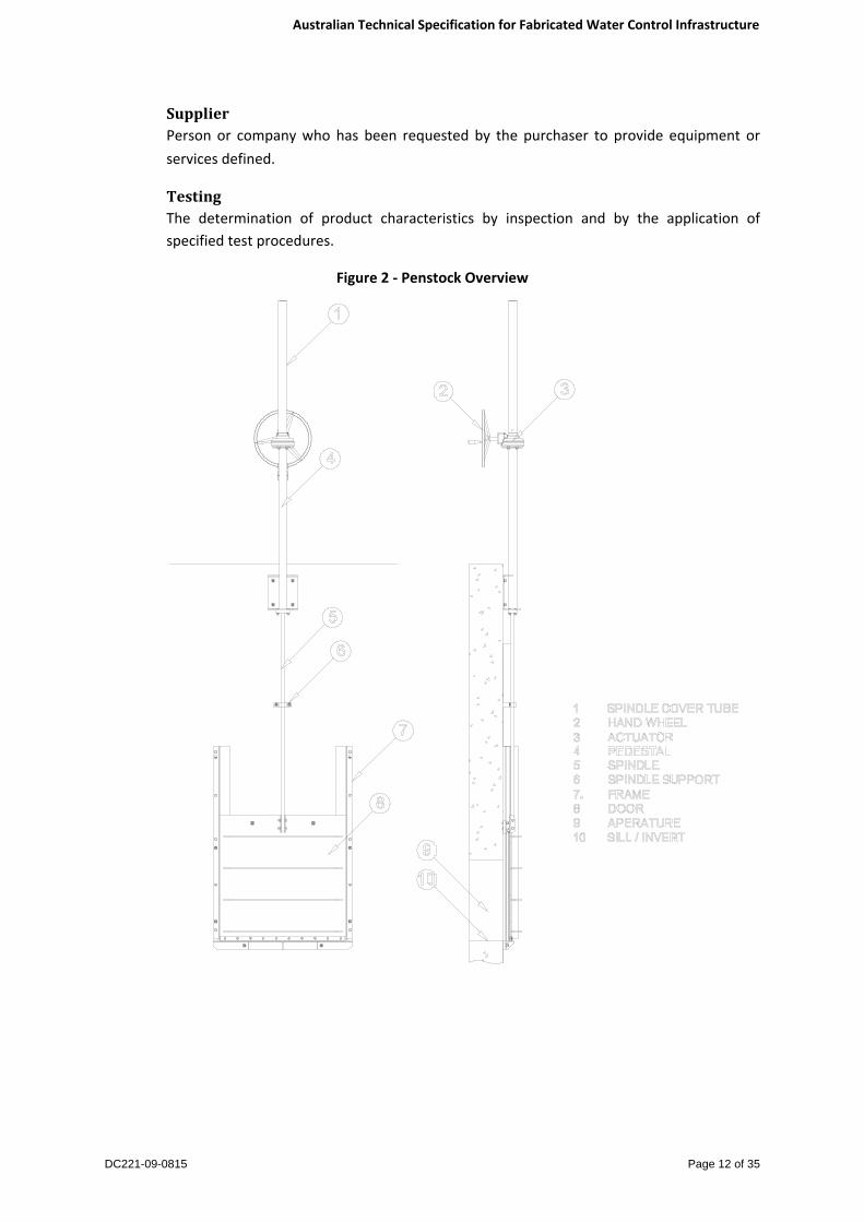
ApertureThe opening formed by the frame and the door. The aperture size is designated as the width followed by the height. (Figure 2)
CreviceA narrow but deep gap which may be initiating locations for attack in corrosive liquids or when exposed to moist atmospheres.
DoorA door retained within a frame that isolates water when in a fully closed position. (Figure 2)
FrameA fabrication that retains and guides the door and secures the WCD to the structure. (Figure 2)
HeadstockHorizontal frame members attached across the top of the side frame members on which the actuator mounts.
PedestalA column attached to the top of the structure on which the actuator mounts. (Figure 2)

Australian Technical Specification for Fabricated Water Control Infrastructure
DC221-09-0815 Page 10 of 35
WCDAn actuated valve comprising a door and frame secured to a structure that regulates or isolates the flow of water.
HeadWater height above the invert of the aperture, expressed in metres.
Sill/InvertThe upper surface of the frame aperture’s lower horizontal frame member. (Figure 2)
InspectionandTestPlan(ITP)An ITP is a document that records all inspection and testing requirements relevant to a specific process. The ITP shall identify items of materials and work to be inspected and tested, by whom and at what stage or frequency, as well as Hold and Witness points, references to relevant standards, acceptance criteria and records to be maintained. The ITP shall cover the whole fabrication process from design through to delivery.
LeakageWater that passes between the door and the frame when the door is fully closed.
ManufacturerAn entity responsible for the selection, processing and control of product components and for the processing equipment that collectively result in the manufactured product.
MaximumStaticHeadThe maximum possible differential head to which the WCD can be subject to in service, expressed in metres.
NotationStatements expresses by the use of the word ‘shall’ are mandatory or ‘normative’ requirements of the specification. Statements expressed by the use of ‘should’ or ‘may’ are informative but not mandatory and are provided only for information and guidance.
Notes in the specification text are informative. Notes in that form part of Specification Tables are normative. The term ‘specified’ includes requirements of the specification and requirements stated or referenced in other project documentation.
Owner/PurchaserThe “owner” of the assets (or operation) or the organisation that will operate the processing system, or the organisation’s authorised representative. The owner may be the purchaser of the asset or may be dealing through an intermediary.
OperatorPlatformLevelThe level that which the operator stands to actuate the WCD.
Off‐SeatingA WCD design where water pressure is forcing the door away from the frame. (Figure 1)
On‐SeatingA WCD design where water pressure is forcing the door onto the frame. (Figure 1)

Australian Technical Specification for Fabricated Water Control Infrastructure
DC221-09-0815 Page 11 of 35
Figure 1 ‐ ON and OFF Seating Overview
QualitySystemA management system that establishes, documents, implements and maintains organizational structures, resources, responsibilities, processes and procedures for the manufacture of a product and provision of product related services in accordance with the requirements of AS/NZS ISO 9001.
SealsResilient material attached to the door or frame to prevent leakage.
SeatHorizontal and vertical bearing surfaces that support the door and provide a flat mating surface for the seals to contact with.
SiteThe location that the WCD is to be installed and operated.
StopboardAn isolation structure comprising a frame secured to a structure with a manually installed single board or multiple boards that regulates or isolates the flow of water. Single piece boards are also referred to as Bulkheads
Australian Technical Specification for Fabricated Water Control Infrastructure
DC221-09-0815 Page 12 of 35
SupplierPerson or company who has been requested by the purchaser to provide equipment or services defined.
TestingThe determination of product characteristics by inspection and by the application of specified test procedures.
Figure 2 ‐ Penstock Overview

Australian Technical Specification for Fabricated Water Control Infrastructure
DC221-09-0815 Page 13 of 35
2.2 UnitsThe System International (SI) units of measurement shall be employed on all drawings, specifications, schedules, and any other technical documentation.
2.3 ConflictinDocumentationShould there be any conflict between the documents contained in or referred to in this Specification, then the order of precedence shall be:
a) Statutory Authority
b) Purchaser’s Specification
c) This Specification
d) Other Process Specification
e) Australian Standards
f) International Standards
Should the supplier identify any such conflict, he shall immediately advise the purchaser in writing and shall obtain the purchaser’s agreement to the proposed method of resolution before proceeding.
3 Systems
3.1 SupplierAccreditationFabrication for the water/wastewater industry requires specific knowledge and skills. For fabrication involving the use of stainless steel products of any grade, fabricators who are ASSDA accredited or equivalent shall be used. Evidence supporting equivalent knowledge and competence shall be supplied where it is proposed to use a fabricator who is not ASSDA accredited. The required competencies and the expected organisational requirements are listed in the ASSDA Accreditation application documents available for free download from www.assda.asn.au.
3.2 ITPAn ITP shall be provide for each type of WCD
3.3 QualitySystemsThe processes for the design manufacture, testing, supply, transportation, handling and delivery of the product to be supplied in accordance with this specification shall form part of a documented quality system. The system shall be certified by a certification body to AS/NZS ISO 9001.

Australian Technical Specification for Fabricated Water Control Infrastructure
DC221-09-0815 Page 14 of 35
3.4 OccupationalHealth&Safety(OH&S)andEnvironmentalComplianceThe supplier shall have systems in place to ensure compliance with the relevant OH&S, public health and environmental regulations, codes of practice and laws.
3.5 SupplierCapabilityProfileThe supplier shall provide a capability statement covering past work and comparable references, competence and availability of equipment and personnel and any other information supporting the supplier’s ability to satisfactorily complete the job.
3.6 ApprovalsandRequiredInspectionsThe owner’s specification shall provide details of codes or standards which shall be satisfied beyond the statutory design, OH&S and environmental requirements. This includes but is not limited to bodies that may need to inspect or approve the equipment or installations. The allocation of cost and time involved in satisfying the requirements of this sub‐section shall be agreed between owner and supplier.
4 DesignRequirements
4.1 DesignScopeThis Specification is intended to define the minimum requirements only and shall not limit any supplier’s responsibility to complete a satisfactorily operating piece of equipment or installation, nor exclude suggestions or improvements.
4.2 GeneralDesignConsiderationsThese general considerations apply to all fabricated and installed items and shall be considered in conjunction with the specific component requirements.
4.3 ProjectSpecificRequirementsA table has been provided in Appendix A of this document in which site specific requirements are to be listed by the client.
4.3.1 DesignLifeProvide a minimum working life of 25 years for non‐wearing parts. The supplier shall nominate the expected life of wearing components and nominate service periods required to achieve this working life.
4.3.2 DesignResponsibilityGeneral Arrangement (GA) drawings and relevant calculations pertaining to the design of the item(s) shall be submitted to the purchaser for review prior to commencement of fabrication, if so requested by the purchaser. The purchaser will sign off on OH&S requirements, process function, materials selection, installation dimensions and the environmental requirements. The purchaser shall not certify the fabricator’s design or calculations but merely the general arrangement drawings.

Australian Technical Specification for Fabricated Water Control Infrastructure
DC221-09-0815 Page 15 of 35
Operation of the installed plant (including maintenance and frequency) is the responsibility of the asset owner. The plant design shall be based on the operating practices as specified by the purchaser.
Manuals shall identify all features that are crucial to the safe and proper functioning of the equipment.
The design performance and the means of measuring the actual performance shall form part of the design. The design shall include means of measurement of critical parameters.
4.3.3 WeldedJointsJoint design shall consider the requirements for corrosion resistance, mechanical durability and align with AS 1554.6 for Stainless Steel and AS1665 for Aluminium.
4.3.4 EnvironmentalConsiderationsWhere service or life cycle guarantees are required, the operating environment shall be clearly specified by the purchaser.
4.4 GeneralThe WCD or stopboard shall:
4.4.1 ActuationBe manually or automatically operated i.e. electrically, hydraulically or pneumatically operated. Automated actuators should include a manual override.
4.4.2 ImpactLoadsIn waterways that are subject to flooding and/or floating debris, door shall be checked for impact loading and/or debris mat formations. Impact loads shall be determined using a rational approach, as concentrated loads acting horizontally at the most critical location at or below the design flood elevation.
Recommended input parameters:
• 2 tonne log • Water velocity of 1m/sec • Stopping distance of 75mm
This requirement should be noted in Appendix A of this document.
4.4.3 LeakageRateOn head pressures up to 5 metres, acceptable leakage rates shall be:
• Less than 0.1 litres per minute per metre of seal periphery for wedge type gates, • Less than 0.3 litres per minute per metre of seal periphery for all other types of water
control gates, and • Less than 0.5 litres per minute per metre of seal periphery for stopboards or
bulkheads.

Australian Technical Specification for Fabricated Water Control Infrastructure
DC221-09-0815 Page 16 of 35
For head pressure 5 metres and over, acceptable leakage rates shall be calculated using the following formula:
Rlm = 0.1 + 0.067 Hos Where:
Hos = on/or off – seating head, in metres. Rlm = leakage rate in litres/minute per metre of seal
4.4.4 MaximumHeadPressureandSeatingBe designed for isolation of the aperture whilst under the maximum specified On‐ and/or Off‐seating head pressure. Details of this are be provided in Appendix A of this document.
4.4.5 DesignHeadPressureWhere appropriate to the design of the WCD, a safety factor shall be specified as a multiplication of the maximum head pressure, as per AS/NZS 1170.0 clause 4.2.3. Specific requirements are to be provided in Appendix A of this document.
4.4.6 TailWaterIf tail water is present on the site it can dramatically reduce the load on the gate leaf and the load required to actuate the gate leaf, details of this should be provided in Appendix A of this document so as to avoid “over sizing” components during design.
4.5 CivilDesignIt is recommended that the WCD supplier is consulted prior to civil design being finalised to ensure that critical structure dimensions for a given WCD design and size have been met. With existing civil structures the WCD shall be designed to minimise civil modifications.
4.6 CivilApertureDimensionsClient to specify these dimensions in Appendix A of this document
Note: For apertures where the width exceeds twice the height a dual spindle actuation system shall be used.
4.7 FrameThe frame shall be designed such that under the specified design head pressure:
4.7.1 StainlessSteelThe maximum stress shall be less than 50% of the minimum proof stress given in Australian Stainless Steel Reference Manual 2008 ‐ Section 3.4. The suggested horizontal and vertical deflection limit should be less than 1/500th of the critical span however it should have no influence on the function of the WCD.
4.7.2 AluminiumThe stress analysis of the frame shall comply with AS/NZS 1664.2 or AS/NZS 1664.1. The suggested horizontal and vertical deflection limit should be less than 1/300th of the critical span however it should have no influence on the function of the WCD.

Australian Technical Specification for Fabricated Water Control Infrastructure
DC221-09-0815 Page 17 of 35
4.7.3 FrameSealShall be mounted and sealed to the wall with a suitable approved elastomeric or grout sealing system. Manufacturer to specify in general arrangement drawings what system is to be utilised. The method of sealing shall be suitable for the environment it will be exposed to.
4.7.4 FixingProvide a means of fixing the frame to the structure, whilst maintaining free movement of the door for the full length travel and support a minimum of 50% of the door height when in the fully raised position.
4.7.5 NumberofAnchorsSpecify location, size, and quantity of chemical anchors for installation to prevent deflection of the frame under the maximum specified design head pressure.
4.7.6 SealReplacementAllow for the replacement of all the seals without removing the frame from the structure.
4.7.7 LiftingPointsInclude lifting points for lifting during handling and installation.
4.7.8 TemporaryBracingIf required Temporary bracing shall be fitted to frame to ensure that the frame is damage and distortion free during transport, handling, and installation.
4.8 DoorThe door shall be designed such that under the specified design head pressure:
4.8.1 StainlessSteelThe maximum stress shall be less than 50% of the minimum proof stress given in Australian Stainless Steel Reference Manual 2008 ‐ Section 3.4. The suggested horizontal and vertical deflection limit should be less than 1/500th of the critical span.
4.8.2 AluminiumThe stress analysis of the door shall comply with AS/NZS 1664.2 or AS/NZS 1664.1. The suggested horizontal and vertical deflection limit should be less than 1/300th of the critical span however it should have no influence on the function of the WCD.
4.8.3 RemovalBe designed for easy removal for maintenance.
4.8.4 IsolationProvide flow isolation within the specified leakage rates when fully closed and when under the maximum specified head conditions.
4.8.5 LiftingPointsInclude lifting points for lifting during handling, installation and maintenance.

Australian Technical Specification for Fabricated Water Control Infrastructure
DC221-09-0815 Page 18 of 35
4.9 Headstock/PedestalThe headstock/pedestal shall be designed such that the axial forces generated from the greater of actuator at stall torque, or 270N rim pull force applied to the handwheel:
4.9.1 StainlessSteelThe maximum stress shall be less than 50% of the minimum proof stress given in Australian Stainless Steel Reference Manual 2012 ‐ Section 3.4. The suggested horizontal and vertical deflection limit should be less than 1/500th of the critical span.
4.9.2 AluminiumThe stress analysis of the door shall comply with AS/NZS 1664.2 or AS/NZS 1664.1. The suggested horizontal and vertical deflection limit should be less than 1/300th of the critical span however it should have no influence on the function of the WCD.
4.9.3 RemovalBe designed to allow removal of the door from the frame without causing structural damage.
4.10 SealsSealing shall be provided at the sides, bottom and if required the top of the door. Seals shall be resilient, providing contact with the door or frame. Seals shall be mounted on the door or frame and be replaceable without requiring removal of the frame from the structure or by causing structural damage to the frame. Resilient seals shall not have glued joints. The seal material type and durometer hardness shall be specified by the manufacturer.
4.11 SpindlesSpindle design shall be checked using Euler’s Buckling formula. Spindles shall be designed so that they are of sufficient section to prevent buckling or deformation when subjected to axial forces generated from:
• the actuator at maximum stall torque, and • 270N rim pull force applied to the handwheel.
Intermediate spindle supports shall be provided as required.
Should spindles of a rising type be offered, spindle protection in the form of a polycarbonate, stainless steel or aluminium cover tube shall be provided. Cover tube material requirements should be listed in Appendix A of this document.
Adjustable limit nuts shall be provided on all rising spindles to limit door travel and to prevent buckling of the spindle due to application of excessive load.
Spindles shall have suitable thread finishes that will avoid excessive wear of components.
Lubrication of spindles should be considered during design and specified in the Operations and Maintenance manual.

Australian Technical Specification for Fabricated Water Control Infrastructure
DC221-09-0815 Page 19 of 35
Note: For ease of maintenance and wherever possible spindles should be of the rising type.
4.12 ActuationThe actuator shall be manual or automated and be designed as per below:
• Sized to provide a minimum of 1.3 times the required breakaway torque to drive the door under the maximum operating head pressure.
• Designed such that a maximum rim pull force 180N applied to the handwheel shall actuate the WCD.
• The centreline of handwheels is to be located between 900‐1200mm above the operator platform level of the structure.
• Handwheels should have a maximum diameter of 600mm • The handwheel direction to close the door is to be specified by the owner/purchaser in
Appendix A of this document • The Handwheel orientation is to be specified in Appendix A of this document. • Actuator protective coatings are to be as per the actuator manufacturer’s standard
coatings unless otherwise specified by the owner/purchaser. • Input shafts on manual gear operators shall be stainless steel. • Required actuator duty shall be specified by the owner/purchaser in Appendix A of this
document. • For mains powered automated sites the travel speed shall be a minimum of 250mm
per minute, for remote solar powered sites this minimum travel speed may be lower to reduce power consumption.
Note: Electric multi turns actuators may have a limited run time due to their potential to overheat. The length of time that they can run is wholly dependent on the load the actuator is subjected to. Actuator suppliers and WCD manufacturers should be consulted to determine the most appropriate type of actuation.
4.13 CableActuationFor WCD designs that utilise a cable actuation system, in addition to the above points the hoist mechanism design shall:
• Include 316 stainless steel cables with a minimum breaking load as specified in AS1418.1
• The rope drum diameter and groove geometry shall comply with AS 1418.1 or to the cable manufactures requirements.
• The idler pulley /sheave diameter and groove geometry shall comply with AS 1418.1 or to the cable manufactures requirements.
• A suitable actuator/gearbox combination that will prevent back winding. • The drive shaft shall comply with AS 1403 when under the maximum torque required
to actuate the WCD.
Note: Idler pulleys are typically used to guide the cable and achieve appropriate angles between the cable and the door when the actuation system is located well above the WCD. When using idler pulleys it is important to consider the maximum fleet angle of the cable

Australian Technical Specification for Fabricated Water Control Infrastructure
DC221-09-0815 Page 20 of 35
feeding on to the rope drum. During actuation this angle shall be a maximum of 5º. As an approximate guide, the distance between the rope drum and idler pulley centrelines should be a minimum of five (5) times the rope drum diameter.
4.14 FastenersFasteners shall be grade A70 or A80. Threads shall comply with AS 1275. Bolts and screws shall comply with the dimensions contained in AS 1111.1 and nuts to AS 1112.3. Bolts shall be sized so that a minimum of one and a half threads shall protrude and thread protrusions shall not exceed one bolt diameter. All fasteners shall comply with the minimum material requirements of Table 1.
Note: Fasteners supplied to ISO 3506 grade A4 shall be deemed to be equivalent to grade 316 stainless steel.
4.15 Transport&HandlingThe designer shall take into account static and dynamic loads imposed on the door and frame during transportation and erection/installation as well as service loads. If temporary supports are required, their location, installation and removal shall not induce defects.
Weights of all major separable components shall be clearly identified.
Suitable lifting points shall be included on the door and frame.
Lifting points shall be designed and positioned so as to ensure the equipment can be lifted, transported and installed without causing damage to the equipment or associated plant. Restrictions of access for transport, unloading and installation shall be considered.
5 Materials
5.1 MaterialsGradeSelectionThe grade of material selected shall be the responsibility of the owner/purchaser.
The following guidelines are included to assist the purchaser. The WCD shall be constructed from the materials detailed in Table 1. The stated material grades represent the minimum requirements.
The type of material/grade used shall be selected according to the environment in which it will be operating. Guidelines for stainless steel selection for Waters and Waste Water Service are shown in Table 2. The assumptions made for these guidelines are included in the table.
Aluminium should typically only be used in freshwater applications or for short periods only in higher chloride applications.
Table 1 ‐ WCD Material Requirements
Component Material Standard Grade

Australian Technical Specification for Fabricated Water Control Infrastructure
DC221-09-0815 Page 21 of 35
Component Material Standard Grade
Frame
Stainless Steel ASTM A240M 316L & Duplex 2205,
2507
Aluminium marine grade
AS/NZS 1734
5083‐H321/H116, 6061‐ T6, 6351‐T5,
6005A‐T5
Door
Stainless Steel ASTM A240M 316L & Duplex 2205,
2507
Aluminium marine grade
AS/NZS 1734
5083 H321/H116 6061 T6, 6351 T5
Fasteners Stainless Steel ASTM A276 316 & Duplex 2205,
2507
Spindle
Stainless Steel ASTM A276 4311, 316 & Duplex
2205, 2507
Drive Nut Aluminium Bronze Manganese Bronze
Ertacetal
Actuator input shaft Stainless Steel ASTM A276 316
Anchor Bolts (Chemical)
Stainless Steel ASTM A276 316 & Duplex 2205,
2507
Spindle extension Stainless Steel ASTM A276 316
Materials of equivalent or superior quality may be acceptable subject to approval for use by the owner/purchaser.
The most important considerations to achieve optimum stainless steel corrosion performance are to choose the correct grade for the chloride, chlorine content and temperature of the water.
1 431 stainless steel is not suitable for tropical or marine environments.

Australian Technical Specification for Fabricated Water Control Infrastructure
DC221-09-0815 Page 22 of 35
Table 2 ‐ Suitability of Stainless Steel in Waters
Chloride level ppm2 Stainless Steel Grade <200ppm 304L, 316L
200‐1000ppm 316L,duplex alloy 2205
1000‐3,600 ppm Duplex alloy 2205, 6%Mo super‐austenitic,
super‐duplex >3,600ppm 6%Mo super‐austenitic, super‐duplex
15,000 – 26,000 ppm(seawater) 6%Mo super‐austenitic, super‐duplex
5.2 Non‐metallicMaterialsWhere non‐metallic materials are used for WCD components they shall be fit for the intended purpose. They shall exhibit dimensional stability when exposed to weather, sunlight and where relevant after extended periods of immersion. Any such material exposed to direct sunlight shall be UV stabilised.
5.3 SealsSeals shall be manufactured from a material that is not injuriously affected by the fluid, temperature or environmental conditions to which the seals will be subjected to in service.
The following guidelines are included to assist the purchaser. The WCD guides and seals shall be constructed from the materials detailed in Table 3.
The stated material grades represent the minimum requirements
Materials of equivalent or superior quality may be acceptable subject to approval for use by the owner/purchaser.
Table 3 ‐ WCD Guide & Seal Material Requirements
Component Material Standard Grade
Door Guides Ultra High Molecular Weight Polyethylene
(UHMWPE)
Ultra High Molecular Weight Polyethylene
(UHMWPE)
Door seals EPDM, Neoprene, Plasticised PVC &
UHMWPE AS1646/AS2369.2
EPDM, Neoprene, Plasticised PVC &
UHMWPE
2 These guidelines apply for ambient temperature, neutral pH and chlorine levels less than 2ppm for grade 304 stainless steel, and 5ppm for grade 316 stainless steel.

Australian Technical Specification for Fabricated Water Control Infrastructure
DC221-09-0815 Page 23 of 35
5.4 FabricationandWeldingofStainlessSteels
5.4.1 ColdFormingEquipment used to cold form stainless steel shall utilise protection to eliminate contamination by other materials during this process. Appropriate radii shall be specified and edge nicks avoided when folding to prevent stress cracking.
5.4.2 StainlessSteelPreparationThe fabrication methods and techniques shall not cause any damage and/or failure that would lead to reducing the designed service life. The material shall only be cut to size by machining, grinding, shearing, laser, water jet, or plasma arc‐cutting. Material shall not be cut using “oxy‐cutting” methods. All burrs and ragged edges shall be removed prior to any welding.
5.4.3 StainlessSteelWelding Weld category shall be equivalent to Category 1B surface finish II (a) of AS/NZS 1554.6. All welds shall be continuous.
5.4.4 QualificationofWeldingProcedureA weld procedure (i.e. the weld preparation, the welding consumables and welding parameters) shall be qualified before welding commences.
A welding procedure shall be established and the applicable parameters listed in the welding Procedure Qualification Record (PQR), which shall be held as a record and shall be available for examination.
A welding procedure specification shall be developed from the PQR, based on the limits of the essential variables of Clause 4.11 of AS/NZS 1554.6 and made available to the welder during fabrication.
The welding procedure may be approved on the welding procedure sheets by a representative of the owner.
5.4.5 MethodofQualificationofWeldingProcedureA welding procedure shall be qualified by one of the following methods:
a) A prequalified procedure in accordance with Clause 5.4.6. b) Production of documentary evidence of relevant prior experience by the fabricator. c) Production of a suitable length of test piece of the same joint, material type, material
thickness, surface finish, and edge preparation as the component upon which the procedures are to be applied, and testing it accordance with Clause 4.6 of AS/NZS 1554.6 where the type of joint allows such testing.
d) Preparation of a special test piece, such as shown in Figure 4.6.3 of AS/NZS 1554.6, which simulates as closely as practicable the weld preparation, material type and direction of rolling, material thickness, edge preparation, surface finish, welding conditions and conditions of restraint to be used in production, and testing it in accordance with Clause 4.6 of AS/NZS 1554.6

Australian Technical Specification for Fabricated Water Control Infrastructure
DC221-09-0815 Page 24 of 35
e) Destructive testing of a prototype joint, structure or component. f) A welding procedure qualified by another fabricator, see Clause 5.4.7.
5.4.6 PrequalifiedWeldingProceduresThe welding procedure shall be deemed to be prequalified when:
g) Joint preparations are prequalified in accordance with Clause 4.5 of AS/NZS 1554.6 h) Weld consumables are prequalified in accordance with Clause 4.6 of AS/NZS 1554.6 i) The workmanship, welding techniques, including preheat and inner run temperature
comply with AS/NZS 1554.6 j) Documentary evidence is available of satisfactory macro tests in accordance with
Clause 4.7.4 and Table 4.7.1 of AS/NZS 1554.6,including a satisfactory macro or a sketch or a photograph, showing the position number, the sequence of runs, the minimum leg length, the throat thickness and the scale of the sketch.
And:
k) For Super Duplex and other speciality metals and if required by the owner, documentary evidence of satisfactory corrosion tests are available. The details of the type of corrosion tests and acceptance criteria should be agreed between the owner and manufacturer.
The extent of testing required on the welding procedure test piece shall be in accordance with Table 4.6.2 of AS/NZS 1663.6
Prequalified procedures shall be fully documented.
5.4.7 PortabilityofQualifiedWeldingProceduresA welding procedure qualified by one fabricator shall be valid for use by a second fabricator, provided that:
l) The original qualification tests were carried out in accordance with AS/NZS 1665, and were fully documented.
m) The second fabricator has adequate equipment and facilities and demonstrates successful welding of welder qualification tests or a macro test using the procedure.
n) The application of the welding procedure is acceptable to both manufacturer and the owner.
o) The welding procedure identifies the original and second fabricator.
5.4.8 WeldingPersonnelWelding shall be carried out under the supervision of a welding supervisor employed by the manufacturer. The welding supervisor shall ensure that welding is carried out as specified in the plans and specifications. Such a supervisor shall have (a) served an apprenticeship in an appropriate metal trade and during it, or subsequent thereto, has had a minimum of five (5) years experience in the fabrication of welded steel structures, or (b) has had at least seven (7) years experience in the fabrication of welded steel structures, or (c) hold an appropriate qualification as listed in point 4.12.1 of AS/NZS 1554.6

Australian Technical Specification for Fabricated Water Control Infrastructure
DC221-09-0815 Page 25 of 35
All welders shall be qualified to carry out the required weld procedures that will be used on the project, the names of welders together with details of any tests they have passed shall be recorded shall be made available for inspection for the duration of the job. The qualification date for welder qualifications for the required welds shall be no older than twelve (12) months from commencement of the job.
5.4.9 WeldExaminationFor all grades of stainless steel, the extent of non‐destructive weld examination shall be agreed between client and manufacturer but as a minimum should include 100% visual scanning, 10% visual examination and 10% liquid penetrate.
5.4.10 FabricationAll fabrication of stainless steel components shall be carried out in a manner which will avoid contamination by other materials e.g. carbon steel. All cutting discs and other tools used shall be dedicated for use on stainless steel. Wire brushes shall be stainless steel type. Stainless steel products shall be stored separately from mild steel and from other materials that can result in contamination. Contamination by carbon steel (or low alloy steel, cast iron) or by salt shall be avoided, as these reduce the corrosion resistance of the steel. Contamination of stainless steel products by carbon or carbonaceous materials is to be avoided (especially if the material is to be welded). This includes oil, grease and paint. Do not walk on unprotected stainless steel products as this may transfer these materials plus other soils.
All Duplex grades with PRE>34 shall be capable of meeting the requirements of ASTM G923 corrosion testing.
5.4.11 WeldingConsumablesAll welding consumables shall be handled in accordance with the manufacturer’s instructions and maintained clean and dry.
5.4.12 ChemicalCleaningAfter fabrication all stainless steel components shall be cleaned. Particular attention is required on the welds to remove heat tint, oxides and chromium depleted layer. This may be done by either grinding to produce a surface roughness of less than 0.5 µm Ra or by cleaning with degreasers followed by pickling in hydrofluoric/nitric acid. Acid treatments shall incorporate a clean water rinse followed by exposure to clean air preferably for 24 hours.
Super duplex grades shall be bathed pickled to ASTM A380 in all cases.
5.5 FabricationandWeldingofAluminium
5.5.1 AluminiumPreparationAll fabrication of aluminium components shall be carried out in a manner which will avoid contamination by other materials e.g. carbon steel. All cutting discs and other tools used shall be dedicated for use on aluminium. Aluminium product awaiting fabrication should if

Australian Technical Specification for Fabricated Water Control Infrastructure
DC221-09-0815 Page 26 of 35
possible be stored inside. If stored outside it shall be protected from the weather and stored off the ground on bearers.
5.5.2 AluminiumWeldingWeld category shall be equivalent to category C of AS/NZS 1665. Intermittent welding of aluminium is permitted.
5.5.3 WeldProcedureA weld procedure (i.e. the weld preparation, the welding consumables and welding parameters) shall be qualified before welding commences. The manufacturer shall establish a welding procedure and list the applicable parameters in a document known as the Welding Procedure Qualification Record (WPQR or PQR)
5.5.4 MethodsforQualifyingaWeldingProcedureA welding procedure shall be qualified by one of the following methods:
a) Production of documentary evidence of relevant prior experience by the fabricator. b) Preparation of a standard test plate from which specimens are taken, such as shown in
Figures 4.1 and 4.2 of AS/NZS 1665. The plate shall simulate as closely as practicable the weld penetration, material type, material direction of rolling, material thickness, edge preparation, welding conditions, including welder access and conditions of restraint as used in production. As far as possible, and testing it in accordance with Clause 4.2.5 of AS/NZS 1665.
c) Production of a suitable length of test plate of the same joint type, material type, material thickness and edge preparation as the component upon which the procedures are to be applied. Specimens shall be tested in accordance with Clause 4.2.5 of AS/NZS 1665.
d) Destructive testing of a proto type joint, structure or component. Such testing should be representative of the tests that would normally be required for a standard test plate, or by agreement between the owner and the manufacturer. As far as possible, testing should comply with the requirements of Clause 4.2.5 of AS/NZS 1665.
Verification of welder qualification test samples are to be carried out in a NATA accredited laboratory.
Procedures shall be fully documented.
5.5.5 PortabilityofQualifiedWeldingProceduresA welding procedure qualified by one fabricator shall be valid for use by a second fabricator, provided that:
a) The original qualification tests were carried out in accordance with AS/NZS1665, and were fully documented.
b) The second fabricator has adequate equipment and facilities and demonstrates successful welding of welder qualification tests or a production test plate using the procedure.

Australian Technical Specification for Fabricated Water Control Infrastructure
DC221-09-0815 Page 27 of 35
c) The application of the welding procedure is acceptable to both manufacturer and the owner.
d) The welding procedure identifies the original and second fabricator.
5.5.6 WeldingPersonnelWelding shall be carried out under the supervision of welding supervisor employed by the manufacturer. The welding supervisor shall ensure that welding is carried out as specified in the plans and specifications. Such a supervisor shall have (a) served an apprenticeship in an appropriate metal trade and during it, or subsequent thereto, has had a minimum of five (5) years experience in the fabrication of welded aluminium structures, or (b) has had at least seven (7) years experience in the fabrication of welded aluminium structures, or (c) hold an appropriate qualification as listed in point 4.12.1 of AS/NZS 1665.
All welders shall be qualified to carry out the required weld procedures that will be used on the project, the names of welders together with details of any tests they have passed shall be recorded shall be made available for inspection for the duration of the job. The qualification date for welder qualifications for the required welds shall be no older than twelve (12) months from commencement of the job.
5.5.7 WeldexaminationFor all grades of Aluminium the extent of non‐destructive weld examination shall be agreed between client and manufacturer but as a minimum should include 100% visual scanning and 10% visual examination.
Note: General guidance is provided in WTIA Technical Note 2, “Successful welding of aluminium”.
5.5.8 CleaningAfter fabrication all welded components shall be cleaned to remove oxides and any contaminations from the manufacturing process.
6 PerformanceTests
6.1 GeneralThe WCD shall be tested in accordance with this specification.
6.2 FactoryTestingThe WCD shall be visually inspected to ensure conformance to approved construction drawings and is free from defects in material and workmanship.
6.3 FactoryFunctionalTestingFactory functional testing is an option for agreement between purchaser and supplier but is subject to the size of the WCD. The supplier should be contacted prior to specifying this type of testing to confirm their capabilities and the associated expense. Test reporting to be provided.

Australian Technical Specification for Fabricated Water Control Infrastructure
DC221-09-0815 Page 28 of 35
6.4 FactoryHydrostaticTestingFactory hydrostatic testing is an option for agreement between purchaser and supplier but is subject to the size of the WCD. The supplier should be contacted prior to specifying this type of testing to confirm their capabilities and the associated expense. It shall be carried out with potable water. Test reporting to be provided.
6.5 SiteInstallation,Commissioning&TestingSite Installation, Commissioning & Testing details shall be provided in an Installation Manual and Inspection and Test Plan document.
Acceptance of satisfactory Site Installation, Commissioning, and Testing shall be documented on an Installation and Test Plan Document, to be signed off by the customer and contract principal or authorised representative.
6.6 TestingNotificationThe manufacturer shall be notified at least 24 hours prior to any site inspections or tests.
6.7 AccesstoPlaceofManufactureThe client shall be afforded access, at all reasonable times, to the place of manufacture for a product inspection, subject to prior notification.
7 MarkingandPackagingThe WCD shall be marked and packaged in accordance with the following.
7.1 MarkingThe WCD shall have the following information provided on a stainless steel plate for stainless steel WCDs and aluminium plate for aluminium WCDs permanently fixed to the frame in a location where it can be readily viewed after installation. The information should include manufacturer’s name, model and size, serial number, seating direction, required operating torque, maximum static head, owners name and site identification. Any special marking requirements should be specified in Appendix A of this document.
7.2 PackagingThe product shall be packaged with appropriate protection which shall prevent damage or defects as a result of handling, storage or transportation.
7.3 MarkingofPackagingThe product shall be clearly identified on the outside of any protective packaging.
8 Manuals
8.1 FormatandLanguageThe WCD shall be supplied complete with appropriate installation, operation and maintenance instructions or manuals, in clear diagrammatic and text format, in English.

Australian Technical Specification for Fabricated Water Control Infrastructure
DC221-09-0815 Page 29 of 35
8.2 InstallationInstructionsThe manufacturer shall submit detailed installation methodology for the WCD. This shall include details of surface preparation, grouting or sealing that is appropriate for the environment, anchor details, and installation tolerances.
8.3 Commissioning,OperationandMaintenanceThe manufacturer shall provide commissioning, operational and maintenance details for the WCD. These shall include details of WCD features, operational adjustments, preventative maintenance requirements and intervals, trouble shooting guidelines, and complete list of spare parts.
9 Transport,HandlingandStorageTransportation, handling and storage facilities shall be designed to prevent product damage or defects. If required, only elastomeric or fabric webbing straps shall be used for lifting purposes during loading, unloading and installation.

Australian Technical Specification for Fabricated Water Control Infrastructure
DC221-09-0815 Page 30 of 35
AppendixA–ProjectSpecificRequirementsFill out one for each different type of WCD
Item Requirement
Project
WCD ID Number
Number of WCD’s
Water or Wastewater service
Chemicals in water or wastewater ‐ Yes/No
(if yes provide details and concentrations separately)
Seating direction – On, Off or both
(Clause 4.4.4)
Clear opening width (m)
(Clause 4.6)
Clear opening height (m)
(Clause 4.6)
Invert RL
Top of concrete RL
Operator platform level RL
Maximum head pressure ‐ On‐seating (m) (Clause 4.4.4 & 4.4.5)
Maximum head pressure ‐ Off‐seating (m) (Clause 4.4.4 & 4.4.5)
Design head pressure (maximum head multiplication factor)
(Clause 4.4.5)
Site subject to Impact Loads ‐ Yes/No
(Clause 4.4.2)

Australian Technical Specification for Fabricated Water Control Infrastructure
DC221-09-0815 Page 31 of 35
Item Requirement
Tail water details
(Clause 4.4.6)
Frame Mounting Sides – embedded, face or channel wall
Frame Mounting Sill – embedded, face or floor (raised)
Frame Material – Aluminium, 316L SS, Duplex 2205, 2507 or other
(Clause 5.1)
Door Material – Aluminium, 316L SS, Duplex 2205, 2507 or other
(Clause 5.1)
Top seal required – Yes/No
Spindle – Rising or Non‐Rising
(Clause 4.11)
Spindle cover tube material ‐ polycarbonate or stainless steel
(Clause 4.11)
Preferred actuator brand – Auma/Limitorque/Rotork or other
Actuation Method – manual handwheel, manual T‐Key, electric, hydraulic or pneumatic.
(Clause 4.12 & 4.13)
Door travel speed (mm/min)
(Clause 4.12)
Handwheel direction to close – clockwise/counter clockwise
(Clause 4.12)

Australian Technical Specification for Fabricated Water Control Infrastructure
DC221-09-0815 Page 32 of 35
Item Requirement
Handwheel orientation – vertical/horizontal
(Clause 4.12)
Operational frequency – cycles/day, cycles/week, cycles/month
(Clause 4.12)
Minimum door travel/lift (m)
Concrete lined/unlined – Yes/No
Sealing material between frame and wall – elastomeric sealant/non shrink grout
(Clause 4.7.3)
Design calculations required – Yes/No
(If yes provide details)
Factory Inspection required ‐ Yes/No
(If yes provide details)
Factory functional testing required – Yes/No
(If yes provide details)
Factory hydrostatic testing required – Yes/No
(If yes provide details)
Specialised marking requirements – Yes/No
(If yes provide details)
(Clause 7)

Australian Technical Specification for Fabricated Water Control Infrastructure
DC221-09-0815 Page 33 of 35
AppendixB–ReferencedStandardsThis specification refers to the following standards.
AS/NZS 1554.6 Structural steel welding – Welding stainless steels for structural purposes
AS/NZS 1664.1 Aluminium Structures – Part 1 – Limit State design
AS/NZS 1664.2 Aluminium Structures – Part 2 – Allowable design stress
AS 1665 Welding of Aluminium Structures
AS/NZS 1170.0 Structural Design Actions – Part 0 – General Principals
AS 1418.1 Cranes, Hoists and Winches – Part 1 – General Requirements
AS 1403 Design of rotating steel shafts
AS/NZS ISO 9001 Quality management systems – requirements
ASTM A240M Standard Specification for Chromium and Chromium‐Nickel stainless steel plate, sheet and strip.
ASTM A380 Standard Practice for Cleaning, Descaling, and Passivation of Stainless Steel Parts, Equipment, and Systems
AS 1275 Metric Screw Threads for Fasteners
AS 1111.1 ISO Hexagon Bolts
AS 1112.3 ISO Hexagon Nuts
ISO 3506 Mechanical Properties of Corrosion Resistant Stainless Steel Fasteners
AS/NZS 1734 Aluminium and aluminium alloys ‐ Flat sheet, coiled sheet and plate
ASTM A276 10 Standard Specification for Stainless Steel Bars and Shapes
AS 1646 Elastomeric seals for waterworks purposes
AS 2369.2 Materials for solar collectors for swimming pool heating
ASTM G923 Standard Test Methods for Detecting Detrimental Intermetallic Phase in Duplex Austenitic/Ferritic Stainless Steels
Australian Stainless Steel Reference Manual 2012

Australian Technical Specification for Fabricated Water Control Infrastructure
DC221-09-0815 Page 34 of 35
AppendixC–GlossaryofTerms
Bulkhead(Baulk)A one piece aluminium or stainless steel door that is used to isolate the flow of water. Bulkheads are typically installed with fixed or mobile crane or davit.
ClearWaterwayWidth(CWW)Is the narrowest width that the that the water passes through, it can be the width between the side frame members or can be the width of the aperture depending on which is narrower
DecantWeirA downwards opening vertical overshot gate.
EPDMEthylene Propylene Diene Monomer is a commonly used seal material.
FabricatorA person employed by the manufacturer to weld or fit out a structure during manufacture.
FactoryThe place of manufacture.
FlapGate(GravityFlap)A gate type where the gate leaf is hinged at the top and is used as a one way or non‐return valve for the end of pipes
IdlerPulleyAn idler pulley is used in cable actuation systems to guide or change direction of the cables.
LayFlat/TiltGateA regulating overshot gate where the door is hinged along the bottom edge and lays down in the downstream direction when opened, this type of gate is typically actuated via a cable hoist system with the cable being attached to the top corners of the door.
Neoprene(orPolychloroprene)Is a commonly used seal material.
Non‐RisingSpindleA spindle that is fixed to and rotated by the actuator, the door is actuated via a threaded drive nut that is fixed to the door.
Overshot/DecantA downwards opening control door where the water flows over the top of the door and typically has seals down each side and across the bottom of the opening.
ProductA single unit or multiple units of manufactured product.
PlasticisedPVCPlasticised (Flexible) Polyvinyl chloride is a commonly used seal material.

Australian Technical Specification for Fabricated Water Control Infrastructure
DC221-09-0815 Page 35 of 35
RimpullForceThe amount of force (N) applied to the rim of the handwheel to manually actuate the WCD.
RisingSpindleA spindle that is fixed to and travels up with the door, typically actuated via a threaded drive nut.
RopeDrumA grooved drum used in cable actuation systems on which cable is wound onto during actuation.
SegmentedStopboards(orStoplogs).A set of multiple aluminium or stainless steel segments that are used to regulate flows/levels or isolates water, these are installed manually or by a lifting device subject to their size.
SidewinderA WCD with a sideways opening door.
TopofConcrete(TOC)Is the uppermost point of the concrete structure and can be but is not necessarily the operator platform level.
TopsealGateAn undershot style door with an additional seal across the top edge of the door and is used for isolating an opening where the water level can rise above the top of the door.
WedgeGateA topseal style door used for isolating openings in high head situations and/or when low leakage rates are required.
UHMWPEUltra High Molecular Weight Polyethylene is a commonly used WCD guide material.
UndershotGateAn upwards opening control door where the water flows underneath the door and has seals down each side and across the bottom of the opening.


